JP7002570B2 - Integrated access system, configuration method, and baseband unit - Google Patents
Integrated access system, configuration method, and baseband unit Download PDFInfo
- Publication number
- JP7002570B2 JP7002570B2 JP2019568332A JP2019568332A JP7002570B2 JP 7002570 B2 JP7002570 B2 JP 7002570B2 JP 2019568332 A JP2019568332 A JP 2019568332A JP 2019568332 A JP2019568332 A JP 2019568332A JP 7002570 B2 JP7002570 B2 JP 7002570B2
- Authority
- JP
- Japan
- Prior art keywords
- bbu
- line speed
- network management
- base station
- station network
- Prior art date
- Legal status (The legal status is an assumption and is not a legal conclusion. Google has not performed a legal analysis and makes no representation as to the accuracy of the status listed.)
- Active
Links
Images


Classifications
-
- H—ELECTRICITY
- H04—ELECTRIC COMMUNICATION TECHNIQUE
- H04W—WIRELESS COMMUNICATION NETWORKS
- H04W88/00—Devices specially adapted for wireless communication networks, e.g. terminals, base stations or access point devices
- H04W88/08—Access point devices
- H04W88/085—Access point devices with remote components
-
- H—ELECTRICITY
- H04—ELECTRIC COMMUNICATION TECHNIQUE
- H04L—TRANSMISSION OF DIGITAL INFORMATION, e.g. TELEGRAPHIC COMMUNICATION
- H04L7/00—Arrangements for synchronising receiver with transmitter
- H04L7/0008—Synchronisation information channels, e.g. clock distribution lines
- H04L7/0012—Synchronisation information channels, e.g. clock distribution lines by comparing receiver clock with transmitter clock
-
- H—ELECTRICITY
- H04—ELECTRIC COMMUNICATION TECHNIQUE
- H04W—WIRELESS COMMUNICATION NETWORKS
- H04W56/00—Synchronisation arrangements
- H04W56/001—Synchronization between nodes
-
- H—ELECTRICITY
- H04—ELECTRIC COMMUNICATION TECHNIQUE
- H04W—WIRELESS COMMUNICATION NETWORKS
- H04W80/00—Wireless network protocols or protocol adaptations to wireless operation
- H04W80/08—Upper layer protocols
-
- H—ELECTRICITY
- H04—ELECTRIC COMMUNICATION TECHNIQUE
- H04W—WIRELESS COMMUNICATION NETWORKS
- H04W88/00—Devices specially adapted for wireless communication networks, e.g. terminals, base stations or access point devices
- H04W88/08—Access point devices
- H04W88/10—Access point devices adapted for operation in multiple networks, e.g. multi-mode access points
-
- H—ELECTRICITY
- H04—ELECTRIC COMMUNICATION TECHNIQUE
- H04W—WIRELESS COMMUNICATION NETWORKS
- H04W88/00—Devices specially adapted for wireless communication networks, e.g. terminals, base stations or access point devices
- H04W88/18—Service support devices; Network management devices
- H04W88/181—Transcoding devices; Rate adaptation devices
-
- H—ELECTRICITY
- H04—ELECTRIC COMMUNICATION TECHNIQUE
- H04W—WIRELESS COMMUNICATION NETWORKS
- H04W92/00—Interfaces specially adapted for wireless communication networks
- H04W92/16—Interfaces between hierarchically similar devices
- H04W92/20—Interfaces between hierarchically similar devices between access points
Landscapes
- Engineering & Computer Science (AREA)
- Computer Networks & Wireless Communication (AREA)
- Signal Processing (AREA)
- Mobile Radio Communication Systems (AREA)
Description
本出願の実施形態は、通信分野に関し、詳細には、統合アクセスシステム、構成方法、およびベースバンドユニットに関する。 Embodiments of this application relate to the field of communications and, in particular, to integrated access systems, configuration methods, and baseband units.
radio dotシステム(Lampsite)は屋内カバレージソリューションである。Lampsiteは、主に、モバイルブロードバンドデータの屋内カバレージに専用される。屋内カバレージのデジタル化を通して、屋内カバレージの構築および保守コストが大幅に低減され、モバイルブロードバンドエクスペリエンスが改善される。 The radio dot system (Lampsite) is an indoor coverage solution. Lampsite is primarily dedicated to indoor coverage of mobile broadband data. Through the digitization of indoor coverage, the cost of building and maintaining indoor coverage will be significantly reduced and the mobile broadband experience will be improved.
モバイル通信マーケットの急速な発展とともに、ユーザは、いつでもおよびどこでも高品質通信ネットワークにアクセスすることをますます期待する。したがって、モバイル通信サービスプロバイダは、呼サービスについてのユーザの要件を最大限に満たすために、リピータを屋外に、建築物内に、地下に、および電波によってカバーされることが困難な別のブラインドエリア中に配設し始めている。LampSiteに基づいて実装された統合アクセスシステムは、複数の規格および複数の周波数帯域をサポートする専用分散システムアーキテクチャである。図1に示されているように、現在の統合アクセスシステムは、ベースバンドユニット(Base Band Unit、BBU)、データ交換ユニット(RHUBとも呼ばれる)、ピコリモート無線ユニット(pico Remote Radio Unit、pRRU)、基地局ネットワーク管理サブシステムなど、複数の製品機能モジュールをさらに含む。 With the rapid development of the mobile communication market, users are increasingly expecting access to high quality communication networks anytime and anywhere. Therefore, mobile communications service providers may place repeaters outdoors, in buildings, underground, and in other blind areas that are difficult to cover by radio waves in order to maximize the user's requirements for call services. It is starting to be arranged inside. The integrated access system implemented based on LampSite is a dedicated distributed system architecture that supports multiple standards and multiple frequency bands. As shown in FIG. 1, current integrated access systems include baseband units (Base Band Unit, BBU), data exchange units (also called RHUB), pico remote radio units (pico Remote Radio Unit, pRRU), It also includes multiple product functional modules, such as the base station network management subsystem.
BBUは集約ノードとして働く。BBUはRHUBに接続され、基地局ネットワーク管理サブシステムはBBUに接続され、RHUBはpRRUに接続される。BBUは、基地局システム全体に対して集中制御および管理を実施するように構成される。RHUBは、BBUとpRRUとの間の通信を実装し、pRRUは、無線周波数信号処理機能を実装する。 BBU acts as an aggregate node. The BBU is connected to the RHUB, the base station network management subsystem is connected to the BBU, and the RHUB is connected to the pRRU. The BBU is configured to perform centralized control and control over the entire base station system. The RHUB implements the communication between the BBU and the pRRU, and the pRRU implements the radio frequency signal processing function.
現在の統合アクセスシステムには少なくとも以下の技術的問題が存在する。BBUのセル能力が高まるにつれて、BBUは、集約ノードとしてRHUBと基地局ネットワーク管理サブシステムを接続する。事業者は、基地局ネットワーク管理サブシステムを使用することによってベースバンドリソースを構成および管理し得る。従来技術では、BBUの無線周波数リソースおよびベースバンドリソースは、同じ基地局ネットワーク管理サブシステムを使用することによって管理される。その結果、異なるリソースの構成および管理は分離されることが不可能であり、サービスアクティブ化およびサービスアップグレードも分離されることが不可能である。結果的に、従来技術では、統合アクセスシステムの信頼性と保守性の両方が低い。 There are at least the following technical issues with current integrated access systems: As the cell capacity of the BBU increases, the BBU connects the RHUB and the base station network management subsystem as an aggregate node. The operator may configure and manage baseband resources by using the base station network management subsystem. In the prior art, BBU radio frequency resources and baseband resources are managed by using the same base station network management subsystem. As a result, the configuration and management of different resources cannot be separated, nor can service activation and service upgrades be separated. As a result, in the prior art, both the reliability and maintainability of the integrated access system are low.
本出願の実施形態は、統合アクセスシステムの内部分離を実装し、統合アクセスシステムの信頼性および保守性を改善するための、統合アクセスシステム、構成方法、およびベースバンドユニットを提供する。 Embodiments of this application provide an integrated access system, configuration method, and baseband unit for implementing internal isolation of an integrated access system and improving the reliability and maintainability of the integrated access system.
第1の態様によれば、本出願の実施形態は、第1のベースバンドユニットBBU、第2のBBU、第1のデータ交換ユニット、第1の基地局ネットワーク管理サブシステム、第2の基地局ネットワーク管理サブシステム、および第1のピコリモート無線ユニットpRRUを含む、統合アクセスシステムを提供する。第1のBBUは第1のデータ交換ユニットに接続され、第1のBBUは第1の基地局ネットワーク管理サブシステムに接続され、第1のBBUは第2のBBUに接続される。第2のBBUは第2の基地局ネットワーク管理サブシステムに接続される。第1のpRRUは第1のデータ交換ユニットに接続される。 According to the first aspect, embodiments of the present application are a first baseband unit BBU, a second BBU, a first data exchange unit, a first base station network management subsystem, a second base station. Provided is an integrated access system including a network management subsystem and a first pico remote radio unit pRRU. The first BBU is connected to the first data exchange unit, the first BBU is connected to the first base station network management subsystem, and the first BBU is connected to the second BBU. The second BBU is connected to the second base station network management subsystem. The first pRRU is connected to the first data exchange unit.
本出願のこの実施形態では、統合アクセスシステムは、第1のBBUおよび第2のBBUという、2つのタイプのBBUを含む。第1のBBUと第2のBBUは、互いに通信するために接続される。加えて、第1のBBUは第1の基地局ネットワーク管理サブシステムに接続され、第2のBBUは第2の基地局ネットワーク管理サブシステムに接続される。したがって、第1のBBUの無線周波数リソースは、第1の基地局ネットワーク管理サブシステムを使用することによって別々に構成および管理され得、第2のBBUのベースバンドリソースは、第2の基地局ネットワーク管理サブシステムを使用することによって別々に構成および管理され得る。このようにして、無線周波数リソースおよびベースバンドリソースは独立して管理されることが可能であり、統合アクセスシステムの信頼性および保守性は大幅に改善される。 In this embodiment of the present application, the integrated access system includes two types of BBUs, a first BBU and a second BBU. The first BBU and the second BBU are connected to communicate with each other. In addition, the first BBU is connected to the first base station network management subsystem and the second BBU is connected to the second base station network management subsystem. Therefore, the radio frequency resources of the first BBU can be separately configured and managed by using the first base station network management subsystem, and the baseband resources of the second BBU are the second base station network. It can be configured and managed separately by using a management subsystem. In this way, radio frequency resources and baseband resources can be managed independently, greatly improving the reliability and maintainability of the integrated access system.
本出願のこの実施形態の可能な設計では、統合アクセスシステムは、第3のBBUおよび第3の基地局ネットワーク管理サブシステムをさらに含む。第1のBBUは第3のBBUに接続され、第3のBBUは第3の基地局ネットワーク管理サブシステムに接続される。本出願の上記の実施形態では、統合アクセスシステムにおいて、第1のBBUはホストBBUとして配設され、第2のBBUと第3のBBUの両方がクライアントBBUとして配設される。加えて、第2のBBUおよび第3のBBUは、それぞれの基地局ネットワーク管理サブシステムに接続される。たとえば、第2のBBUは第2の基地局ネットワーク管理サブシステムに接続され、第3のBBUは第3の基地局ネットワーク管理サブシステムに接続される。したがって、複数の事業者がネットワークを一緒に確立し、確立の後にネットワークリソースを共有するシナリオにおいて、それらの異なる事業者は、第2の基地局ネットワーク管理サブシステムおよび第3の基地局ネットワーク管理サブシステムを別々に使用し、それにより、それらの複数の事業者間でアセット分離、運用および保守分離、ならびにサービスアクティブ化およびアップグレード分離を実装し得る。 In the possible design of this embodiment of the present application, the integrated access system further includes a third BBU and a third base station network management subsystem. The first BBU is connected to the third BBU and the third BBU is connected to the third base station network management subsystem. In the above embodiment of the present application, in the integrated access system, the first BBU is arranged as the host BBU, and both the second BBU and the third BBU are arranged as the client BBU. In addition, the second BBU and the third BBU are connected to their respective base station network management subsystems. For example, a second BBU is connected to a second base station network management subsystem and a third BBU is connected to a third base station network management subsystem. Therefore, in a scenario where multiple operators establish a network together and share network resources after the establishment, those different operators may have a second base station network management subsystem and a third base station network management sub. The systems may be used separately, thereby implementing asset separation, operation and maintenance separation, and service activation and upgrade separation between those multiple operators.
本出願のこの実施形態の可能な設計では、統合アクセスシステムは、第4のBBU、第2のデータ交換ユニット、第4の基地局ネットワーク管理サブシステム、および第2のpRRUをさらに含む。第4のBBUは第2のデータ交換ユニットに接続され、第4のBBUは第4の基地局ネットワーク管理サブシステムに接続され、第4のBBUは第2のBBUに接続され、第2のpRRUは第2のデータ交換ユニットに接続される。統合アクセスシステムにおいて、第1のBBUと第4のBBUの両方がホストBBUとして働き得る。たとえば、第1のBBUおよび第4のBBUは、異なる建築物中に別々にあり得る。第1のBBUおよび第4のBBUは、異なるファイバーチャネルを通して第2のBBUに別々に接続され得る。第2のBBUは、クライアントBBUと複数のホストBBUとの間のサブラック間接続をサポートするために、中央機器ルーム中に配設され得、それにより、1つの中央機器ルームは複数の周囲の建築物をカバーする。 In the possible design of this embodiment of the present application, the integrated access system further includes a fourth BBU, a second data exchange unit, a fourth base station network management subsystem, and a second pRRU. The fourth BBU is connected to the second data exchange unit, the fourth BBU is connected to the fourth base station network management subsystem, the fourth BBU is connected to the second BBU, and the second pRRU. Is connected to a second data exchange unit. In an integrated access system, both the first BBU and the fourth BBU can act as host BBUs. For example, the first BBU and the fourth BBU can be separate in different buildings. The first BBU and the fourth BBU may be separately connected to the second BBU through different Fiber Channels. A second BBU may be located in the central equipment room to support sub-black connections between the client BBU and the plurality of host BBUs, whereby one central equipment room may be located in multiple perimeters. Cover the building.
第2の態様によれば、本出願の実施形態は、統合アクセスシステムに基づく構成方法をさらに提供する。統合アクセスシステムは、第1のベースバンドユニットBBUおよび第2のBBUを含み、第1のBBUは第2のBBUに接続される。本方法は、第1のBBUによって、第1のクロック同期情報を取得するステップであって、第1のクロック同期情報は、第1のBBUのクロック周波数およびクロック位相を含む、ステップと、第1のBBUによって、第1のクロック同期情報を第2のBBUに送るステップとを含む。第1のBBUは、第1のクロック同期情報を第2のBBUに送り得、したがって、第2のBBUは、第1のクロック同期情報に基づいて第2のBBUのローカルクロック情報を構成し、それにより、BBU間でサブラック間クロック同期を実装することができる。たとえば、BBUモードが構成される。基地局ネットワーク管理サブシステムのOMチャネルを通して、第1のBBUはホストBBUモードとして構成され得、第2のBBUはクライアントBBUモードとして構成され得る。複数のBBUのサブラック間集約がサポートされ、したがって、複数の事業者は異なるBBUにアクセスし、それにより、事業者間の運用および保守分離の問題を解決し、BBUアクセスに基づく将来の大容量展開を実装する。加えて、本出願のこの実施形態では、複数のホストBBUと複数のクライアントBBUとの間のサブラック間接続がサポートされ、それにより、1つの中央機器ルームは複数の周囲の建築物をカバーする。 According to a second aspect, embodiments of the present application further provide a configuration method based on an integrated access system. The integrated access system includes a first baseband unit BBU and a second BBU, the first BBU being connected to the second BBU. The method is a step of acquiring the first clock synchronization information by the first BBU, wherein the first clock synchronization information includes the clock frequency and the clock phase of the first BBU, and the first step. Includes a step of sending the first clock synchronization information to the second BBU by the BBU of. The first BBU may send the first clock synchronization information to the second BBU, and therefore the second BBU constitutes the local clock information of the second BBU based on the first clock synchronization information. Thereby, clock synchronization between sub-blacks can be implemented between BBUs. For example, BBU mode is configured. Through the OM channel of the base station network management subsystem, the first BBU may be configured as the host BBU mode and the second BBU may be configured as the client BBU mode. Multi-submarine aggregation of multiple BBUs is supported, thus allowing multiple operators to access different BBUs, thereby resolving operational and maintenance separation issues between operators and future large capacity based on BBU access. Implement the deployment. In addition, in this embodiment of the present application, subblack connections between multiple host BBUs and multiple client BBUs are supported, whereby one central equipment room covers multiple surrounding buildings. ..
本出願のこの実施形態の可能な設計では、統合アクセスシステムは第3のBBUをさらに含み、第3のBBUは第1のBBUに接続され、本方法は、第1のBBUによって、第1のクロック同期情報を第3のBBUに送るステップをさらに含む。第1のBBUがホストBBUとして2つのクライアントBBUに接続されたとき、第1のBBUが第1のクロック同期情報を取得した後に、第1のBBUは、第1のクロック同期情報を第2のBBUおよび第3のBBUに別々に送り得、したがって、第3のBBUは、クライアントBBUとして、第1のBBUの第1のクロック同期情報を受信することもできる。第3のBBUは、第1のクロック同期情報を使用して第3のBBUのローカルクロックソースを補正し、それにより、BBU間でサブラック間クロック同期を実装し得る。 In a possible design of this embodiment of the present application, the integrated access system further comprises a third BBU, the third BBU is connected to the first BBU, and the method is the first by the first BBU. It further includes a step of sending the clock synchronization information to the third BBU. When the first BBU is connected to the two client BBUs as the host BBU, after the first BBU acquires the first clock synchronization information, the first BBU transfers the first clock synchronization information to the second. It can be sent separately to the BBU and the third BBU, and thus the third BBU can also receive the first clock synchronization information of the first BBU as the client BBU. The third BBU may use the first clock synchronization information to correct the local clock source of the third BBU, thereby implementing clock synchronization between subblacks between BBUs.
第3の態様によれば、本出願の実施形態は、統合アクセスシステムに基づく構成方法をさらに提供する。統合アクセスシステムは、第1のベースバンドユニットBBUおよび第2のBBUを含み、第1のBBUは第2のBBUに接続される。本方法は、第2のBBUによって、第1のBBUによって送られた第1のクロック同期情報を受信するステップであって、第1のクロック同期情報は、第1のBBUのクロック周波数およびクロック位相を含む、ステップと、第2のBBUによって、第1のクロック同期情報に基づいて第2のBBUのローカルクロック情報を構成するステップとを含む。第1のBBUは、第1のクロック同期情報を第2のBBUに送り得、したがって、第2のBBUは、第1のクロック同期情報に基づいて第2のBBUのローカルクロック情報を構成し、それにより、BBU間でサブラック間クロック同期を実装することができる。 According to a third aspect, embodiments of the present application further provide a configuration method based on an integrated access system. The integrated access system includes a first baseband unit BBU and a second BBU, the first BBU being connected to the second BBU. This method is a step of receiving the first clock synchronization information sent by the first BBU by the second BBU, and the first clock synchronization information is the clock frequency and the clock phase of the first BBU. A step comprising, and a step of constructing the local clock information of the second BBU based on the first clock synchronization information by the second BBU. The first BBU may send the first clock synchronization information to the second BBU, and therefore the second BBU constitutes the local clock information of the second BBU based on the first clock synchronization information. Thereby, clock synchronization between sub-blacks can be implemented between BBUs.
本出願のこの実施形態の可能な設計では、統合アクセスシステムは第4のBBUをさらに含み、第4のBBUは第2のBBUに接続され、本方法は、第2のBBUによって、第4のBBUによって送られた第2のクロック同期情報を受信するステップであって、第2のクロック同期情報は、第4のBBUのクロック周波数およびクロック位相を含む、ステップをさらに含み、第2のBBUによって、第1のクロック同期情報に基づいて第2のBBUのローカルクロック情報を構成するステップは、第2のBBUによって、第1のクロック同期情報および第2のクロック同期情報に基づいて第2のBBUのローカルクロック情報を構成するステップを含む。第1のクロック同期情報を受信することに加えて、第2のBBUは、第4のBBUの第2のクロック同期情報を受信する。第2のBBUは、第2のクロック同期情報をパースして、第4のBBUのクロック周波数およびクロック位相を取得し得る。第2のBBUと第4のBBUの両方がホストBBUとして働くとき、第2のBBUおよび第4のBBUは、クライアントBBUとして働いている第2のBBUにクロック同期情報を別々に送り得、第2のBBUは、第1のBBUのクロック周波数およびクロック位相、ならびに第4のBBUのクロック周波数およびクロック位相を別々に取得し得る。 In the possible design of this embodiment of the present application, the integrated access system further comprises a fourth BBU, the fourth BBU is connected to the second BBU, and the method is the fourth by the second BBU. A step of receiving the second clock synchronization information sent by the BBU, wherein the second clock synchronization information further includes a step including the clock frequency and clock phase of the fourth BBU, by the second BBU. , The step of configuring the local clock information of the second BBU based on the first clock synchronization information is the second BBU based on the first clock synchronization information and the second clock synchronization information by the second BBU. Includes steps to configure local clock information for. In addition to receiving the first clock synchronization information, the second BBU receives the second clock synchronization information of the fourth BBU. The second BBU may parse the second clock synchronization information to obtain the clock frequency and clock phase of the fourth BBU. When both the second BBU and the fourth BBU act as the host BBU, the second BBU and the fourth BBU may send clock synchronization information separately to the second BBU acting as the client BBU, the second. The BBU of 2 may acquire the clock frequency and clock phase of the first BBU separately, and the clock frequency and clock phase of the fourth BBU.
本出願のこの実施形態の可能な設計では、第2のBBUによって、第1のクロック同期情報および第2のクロック同期情報に基づいて第2のBBUのローカルクロック情報を構成するステップは、第2のBBUによって、第1のクロック同期情報および第2のクロック同期情報から、より高いクロック品質をもつクロック同期情報を選択し、より高いクロック品質をもつクロック同期情報に基づいて第2のBBUのローカルクロック情報を構成するステップを含む。第2のBBUは、第1のBBUおよび第4のBBUによって第2のBBUに別々に送られたクロック同期情報から、より高いクロック品質をもつクロック同期情報を選択し、より高いクロック品質をもつクロック同期情報に基づいて第2のBBUのローカルクロック情報を構成して、第2のBBUが、高いクロック品質をもつクロック情報を使用することを保証し得る。 In a possible design of this embodiment of the present application, the step of constructing the local clock information of the second BBU based on the first clock synchronization information and the second clock synchronization information by the second BBU is a second step. BBU selects the clock synchronization information with higher clock quality from the first clock synchronization information and the second clock synchronization information, and the second BBU local based on the clock synchronization information with higher clock quality. Includes steps to configure clock information. The second BBU selects the clock synchronization information having higher clock quality from the clock synchronization information separately sent to the second BBU by the first BBU and the fourth BBU, and has higher clock quality. The local clock information of the second BBU can be configured based on the clock synchronization information to ensure that the second BBU uses the clock information with high clock quality.
第4の態様によれば、本出願の実施形態は、統合アクセスシステムに基づく構成方法をさらに提供する。統合アクセスシステムは、第1のベースバンドユニットBBUおよび第2のBBUを含み、第1のBBUは第2のBBUに接続され、本方法は、第1のBBUによって、第1の回線速度を更新し、各更新の後に、更新された第1の回線速度においてデータフレームを第2のBBUに送るステップと、第2のBBUが第2の回線速度を更新する各時間の後に、第1のBBUによって、更新された第2の回線速度において第2のBBUによって送られたデータフレームを受信するステップと、第1の回線速度が第2の回線速度に等しいとき、第1のBBUによって、第1の回線速度において第1のBBUのネットワーキング関係情報を第2のBBUに送り、第2の回線速度において第2のBBUによって送られた第2のBBUのネットワーキング関係情報を受信するステップと、第1のBBUによって、第2のBBUのネットワーキング関係情報に基づいて第2のBBUに通信アドレスを割り振り、第1のBBUの通信アドレスを第2のBBUに送るステップと、第1のBBUによって、第2のBBUの通信アドレスに基づいて第2のBBUとの双方向上位レイヤ通信チャネルを確立するステップとを含む。第1のBBUおよび第2のBBUは回線速度オートネゴシエーションを実施し得る。第1のBBUは、第2のBBUに通信アドレスを割り振り、第2のBBUは、第1のBBUの通信アドレスを取得し得る。第1のBBUは、第2のBBUの通信アドレスに基づいて第2のBBUとの双方向上位レイヤ通信チャネルを確立する。回線速度オートネゴシエーション、ネットワーキング関係情報交換、および通信アドレス割振りを通して、上位レイヤ通信チャネルは、手動構成なしに第1のBBUと第2のBBUとの間で自動的に確立され、それにより、手動コストが低減され、エラー確率が減少され得る。たとえば、上位レイヤ通信チャネルは、ホストBBUとクライアントBBUとの間で自動的に確立され、それにより、サービス人員の構成作業負荷およびサイトセットアップの複雑さが低減される。 According to a fourth aspect, embodiments of the present application further provide a configuration method based on an integrated access system. The integrated access system includes a first baseband unit BBU and a second BBU, the first BBU is connected to the second BBU, and the method updates the first line speed by the first BBU. Then, after each update, after each step of sending a data frame to the second BBU at the updated first line speed and each time the second BBU updates the second line speed, the first BBU By the step of receiving the data frame sent by the second BBU at the updated second line speed, and by the first BBU when the first line speed is equal to the second line speed. The step of sending the networking-related information of the first BBU to the second BBU at the line speed of the second BBU and receiving the networking-related information of the second BBU sent by the second BBU at the second line speed, and the first step. A step of allocating a communication address to the second BBU based on the networking-related information of the second BBU and sending the communication address of the first BBU to the second BBU by the BBU of the first BBU, and a second by the first BBU. Includes a step of establishing a bidirectional upper layer communication channel with a second BBU based on the BBU's communication address. The first BBU and the second BBU may perform line speed auto-negotiation. The first BBU may allocate a communication address to the second BBU, and the second BBU may acquire the communication address of the first BBU. The first BBU establishes a bidirectional upper layer communication channel with the second BBU based on the communication address of the second BBU. Through line speed auto-negotiation, networking-related information exchange, and communication address allocation, higher layer communication channels are automatically established between the first BBU and the second BBU without manual configuration, thereby manually costing. Can be reduced and the error probability can be reduced. For example, higher layer communication channels are automatically established between the host BBU and the client BBU, thereby reducing the configuration workload of service personnel and the complexity of site setup.
本出願のこの実施形態の可能な設計では、第1の回線速度が第2の回線速度に等しいとき、本方法は、第1のBBUによって、第1の回線速度において第1のBBUの回線速度能力情報を第2のBBUに送るステップと、第1のBBUによって、第2の回線速度において第2のBBUによって送られた第2のBBUの回線速度能力情報を受信するステップと、第1のBBUの回線速度能力情報および第2のBBUの回線速度能力情報に基づいて第1のBBUによって、第1のBBUと第2のBBUとの間で物理レイヤ通信を実施するために使用される回線速度を判定するステップとをさらに含む。回線速度能力情報は、物理レイヤチャネル上でのBBUの最大送信能力である。第1のBBUおよび第2のBBUは、それぞれの回線速度能力情報を交換し、次いで、第1のBBUの回線速度能力情報および第2のBBUの回線速度能力情報に基づいて、第1のBBUと第2のBBUとの間で物理レイヤ通信を実施するために使用される回線速度を判定する。たとえば、手動構成を実施するために手動リソースを占有することなしに回線速度オートネゴシエーションを実装するために、第1のBBUと第2のBBUとの間で物理レイヤ通信を実施するために使用される回線速度として、第1のBBUの回線速度能力情報と第2のBBUの回線速度能力情報の交差セット中の最大回線速度が選択され得る。 In a possible design of this embodiment of the present application, when the first line speed is equal to the second line speed, the method is performed by the first BBU to the line speed of the first BBU at the first line speed. The step of sending the capacity information to the second BBU, the step of receiving the line speed capacity information of the second BBU sent by the second BBU at the second line speed by the first BBU, and the first step. A line used by the first BBU to perform physical layer communication between the first BBU and the second BBU based on the line speed capability information of the BBU and the line speed capability information of the second BBU. It further includes a step of determining the speed. The line speed capability information is the maximum transmission capability of the BBU on the physical layer channel. The first BBU and the second BBU exchange their respective line speed capacity information, and then the first BBU is based on the line speed capacity information of the first BBU and the line speed capacity information of the second BBU. Determines the line speed used to perform physical layer communication between the and the second BBU. For example, used to perform physical layer communication between a first BBU and a second BBU to implement line speed auto-negotiation without occupying manual resources to perform manual configuration. As the line speed, the maximum line speed in the intersection set of the line speed capacity information of the first BBU and the line speed capacity information of the second BBU can be selected.
本出願のこの実施形態の可能な設計では、第1のBBUによって、第1の回線速度を更新するステップは、第1のBBUによって、第1の期間に基づいて第1の回線速度を更新するステップであって、第1の期間と第2の期間は異なる期間であり、第2の期間は、第2のBBUが第2の回線速度をそれに基づいて更新する期間である、ステップを含む。第1のBBUと第2のBBUの両方が、それぞれの期間に基づいてそれぞれの回線速度値を更新し、第1の期間と第2の期間は異なる期間である。したがって、第1の期間および第2の期間中に、より長い期間およびより短い期間が必ずある。第1のBBUおよび第2のBBUは、第1のBBUと第2のBBUとの間でブラインド回線速度マッチングを試みるために、それぞれの回線速度を周期的に更新し、それにより、手動構成を実施するために手動リソースを占有することなしに回線速度オートネゴシエーションを実装する。 In a possible design of this embodiment of the present application, the step of updating the first line speed by the first BBU updates the first line speed by the first BBU based on the first period. The first period and the second period are different periods, and the second period includes a step in which the second BBU updates the second line speed based on the step. Both the first BBU and the second BBU update their line speed values based on their respective periods, with the first and second periods being different periods. Therefore, there will always be longer and shorter periods during the first and second periods. The first BBU and the second BBU periodically update their respective line speeds in order to attempt blind line speed matching between the first BBU and the second BBU, thereby providing manual configuration. Implement line speed auto-negotiation without occupying manual resources to implement.
第5の態様によれば、本出願の実施形態は、統合アクセスシステムに基づく構成方法をさらに提供する。統合アクセスシステムは、第1のベースバンドユニットBBUおよび第2のBBUを含み、第1のBBUは第2のBBUに接続され、本方法は、第2のBBUによって、第2の回線速度を更新し、各更新の後に、更新された第2の回線速度においてデータフレームを第1のBBUに送るステップと、第1のBBUが第1の回線速度を更新する各時間の後に、第2のBBUによって、更新された第1の回線速度において第1のBBUによって送られたデータフレームを受信するステップと、第2の回線速度が第1の回線速度に等しいとき、第2のBBUによって、第2の回線速度において第2のBBUのネットワーキング関係情報を第1のBBUに送り、第1の回線速度において第1のBBUによって送られた第1のBBUのネットワーキング関係情報を受信するステップと、第2のBBUによって、第1のBBUの通信アドレスを取得するステップと、第2のBBUによって、第1のBBUの通信アドレスに基づいて第1のBBUとの双方向上位レイヤ通信チャネルを確立するステップとを含む。第1のBBUおよび第2のBBUは回線速度オートネゴシエーションを実施し得る。第1のBBUは、第2のBBUに通信アドレスを割り振り、第2のBBUは、第1のBBUの通信アドレスを取得し得る。第1のBBUは、第2のBBUの通信アドレスに基づいて第2のBBUとの双方向上位レイヤ通信チャネルを確立する。回線速度オートネゴシエーション、ネットワーキング関係情報交換、および通信アドレス割振りを通して、上位レイヤ通信チャネルは、手動構成なしに第1のBBUと第2のBBUとの間で自動的に確立され、それにより、手動コストが低減され、エラー確率が減少され得る。 According to a fifth aspect, embodiments of the present application further provide a configuration method based on an integrated access system. The integrated access system includes a first baseband unit BBU and a second BBU, the first BBU is connected to the second BBU, and the method updates the second line speed by the second BBU. Then, after each update, after each step of sending a data frame to the first BBU at the updated second line speed and each time the first BBU updates the first line speed, the second BBU By the step of receiving the data frame sent by the first BBU at the updated first line speed, and by the second BBU when the second line speed is equal to the first line speed. The step of sending the networking-related information of the second BBU to the first BBU at the line speed of the first BBU and receiving the networking-related information of the first BBU sent by the first BBU at the first line speed, and the second step. BBU obtains the communication address of the first BBU, and the second BBU establishes a bidirectional upper layer communication channel with the first BBU based on the communication address of the first BBU. including. The first BBU and the second BBU may perform line speed auto-negotiation. The first BBU may allocate a communication address to the second BBU, and the second BBU may acquire the communication address of the first BBU. The first BBU establishes a bidirectional upper layer communication channel with the second BBU based on the communication address of the second BBU. Through line speed auto-negotiation, networking-related information exchange, and communication address allocation, higher layer communication channels are automatically established between the first BBU and the second BBU without manual configuration, thereby manually costing. Can be reduced and the error probability can be reduced.
本出願のこの実施形態の可能な設計では、第2の回線速度が第1の回線速度に等しいとき、本方法は、第2のBBUによって、第2の回線速度において第2のBBUの回線速度能力情報を第1のBBUに送るステップと、第2のBBUによって、第1の回線速度において第1のBBUによって送られた第1のBBUの回線速度能力情報を受信するステップと、第2のBBUの回線速度能力情報および第1のBBUの回線速度能力情報に基づいて第2のBBUによって、第1のBBUと第2のBBUとの間で物理レイヤ通信を実施するために使用される回線速度を判定するステップとをさらに含む。回線速度能力情報は、物理レイヤチャネル上でのBBUの最大送信能力である。第1のBBUおよび第2のBBUは、それぞれの回線速度能力情報を交換し、次いで、第1のBBUの回線速度能力情報および第2のBBUの回線速度能力情報に基づいて、第1のBBUと第2のBBUとの間で物理レイヤ通信を実施するために使用される回線速度を判定する。たとえば、手動構成を実施するために手動リソースを占有することなしに回線速度オートネゴシエーションを実装するために、第1のBBUと第2のBBUとの間で物理レイヤ通信を実施するために使用される回線速度として、第1のBBUの回線速度能力情報と第2のBBUの回線速度能力情報の交差セット中の最大回線速度が選択され得る。 In a possible design of this embodiment of the present application, when the second line speed is equal to the first line speed, the method is performed by the second BBU, at the second line speed, the line speed of the second BBU. A step of sending the capacity information to the first BBU, a step of receiving the line speed capacity information of the first BBU sent by the first BBU at the first line speed by the second BBU, and a second step. A line used by a second BBU to perform physical layer communication between a first BBU and a second BBU based on the BBU's line speed capability information and the first BBU's line speed capability information. It further includes a step of determining the speed. The line speed capability information is the maximum transmission capability of the BBU on the physical layer channel. The first BBU and the second BBU exchange their respective line speed capacity information, and then the first BBU is based on the line speed capacity information of the first BBU and the line speed capacity information of the second BBU. Determines the line speed used to perform physical layer communication between the and the second BBU. For example, used to perform physical layer communication between a first BBU and a second BBU to implement line speed auto-negotiation without occupying manual resources to perform manual configuration. As the line speed, the maximum line speed in the intersection set of the line speed capacity information of the first BBU and the line speed capacity information of the second BBU can be selected.
本出願のこの実施形態の可能な設計では、第2のBBUによって、第2の回線速度を更新するステップは、第2のBBUによって、第2の期間に基づいて第2の回線速度を更新するステップであって、第2の期間と第1の期間は異なる期間であり、第1の期間は、第1のBBUが第1の回線速度をそれに基づいて更新する期間である、ステップを含む。第1のBBUと第2のBBUの両方が、それぞれの期間に基づいてそれぞれの回線速度値を更新し、第1の期間と第2の期間は異なる期間である。したがって、第1の期間および第2の期間中に、より長い期間およびより短い期間が必ずある。第1のBBUおよび第2のBBUは、第1のBBUと第2のBBUとの間でブラインド回線速度マッチングを試みるために、それぞれの回線速度を周期的に更新し、それにより、手動構成を実施するために手動リソースを占有することなしに回線速度オートネゴシエーションを実装する。 In a possible design of this embodiment of the present application, the step of updating the second line speed by the second BBU updates the second line speed by the second BBU based on the second period. A step, wherein the second period and the first period are different periods, and the first period includes a period in which the first BBU updates the first line speed based on it. Both the first BBU and the second BBU update their line speed values based on their respective periods, with the first and second periods being different periods. Therefore, there will always be longer and shorter periods during the first and second periods. The first BBU and the second BBU periodically update their respective line speeds in order to attempt blind line speed matching between the first BBU and the second BBU, thereby providing manual configuration. Implement line speed auto-negotiation without occupying manual resources to implement.
第6の態様によれば、本出願の実施形態は、統合アクセスシステムに基づく構成方法をさらに提供する。統合アクセスシステムは、第1のベースバンドユニットBBU、第2のBBU、第1のデータ交換ユニット、第2の基地局ネットワーク管理サブシステム、および第1のピコリモート無線ユニットpRRUを含む。第1のBBUは、第2のBBUおよび第1のデータ交換ユニットに別々に接続され、第1のデータ交換ユニットは第1のpRRUに接続され、第2のBBUは第2の基地局ネットワーク管理サブシステムに接続される。本方法は、第1のBBUによって、第1のデータ交換ユニットに対応するリソースおよび第1のpRRUに対応するリソースにスライシング処理を実施して、複数のセクタデバイスグループオブジェクトリソースを取得するステップと、第1のBBUによって、第2の基地局ネットワーク管理サブシステムのリソース構成要求に基づいて複数のセクタデバイスグループオブジェクトリソースから第1のセクタデバイスグループオブジェクトリソースを選択するステップと、第1のBBUによって、第1のセクタデバイスグループオブジェクトリソースを第2のBBUに通知するステップとを含む。第1のBBUは、第1のデータ交換ユニットに対応するリソースおよび第1のpRRUに対応するリソースにスライシング処理を実施して、複数のセクタデバイスグループオブジェクトリソースを取得する。第1のBBUは、第2の基地局ネットワーク管理サブシステムのリソース構成要求に基づいて第2の基地局ネットワーク管理サブシステムに第1のセクタデバイスグループオブジェクトリソースを割り振り、したがって、事業者デバイスは、RHUBおよびpRRUなどの共通リソースを独立して呼び出すことができる。 According to a sixth aspect, embodiments of the present application further provide a configuration method based on an integrated access system. The integrated access system includes a first baseband unit BBU, a second BBU, a first data exchange unit, a second base station network management subsystem, and a first pico remote radio unit pRRU. The first BBU is connected separately to the second BBU and the first data exchange unit, the first data exchange unit is connected to the first pRRU, and the second BBU is the second base station network management. Connected to the subsystem. In this method, the first BBU performs slicing processing on the resource corresponding to the first data exchange unit and the resource corresponding to the first pRRU to acquire a plurality of sector device group object resources. By the first BBU, the step of selecting the first sector device group object resource from a plurality of sector device group object resources based on the resource configuration request of the second base station network management subsystem, and by the first BBU. It includes a step of notifying the second BBU of the first sector device group object resource. The first BBU performs slicing processing on the resource corresponding to the first data exchange unit and the resource corresponding to the first pRRU to acquire a plurality of sector device group object resources. The first BBU allocates the first sector device group object resource to the second base station network management subsystem based on the resource configuration request of the second base station network management subsystem, and thus the operator device. Common resources such as RHUB and pRRU can be called independently.
本出願のこの実施形態の可能な設計では、統合アクセスシステムは、第3のBBUおよび第3の基地局ネットワーク管理サブシステムをさらに含み、第1のBBUは第3のBBUに接続され、第3のBBUは第3の基地局ネットワーク管理サブシステムに接続され、本方法は、第1のBBUによって、第3の基地局ネットワーク管理サブシステムのリソース構成要求に基づいて複数のセクタデバイスグループオブジェクトリソースから第2のセクタデバイスグループオブジェクトリソースを選択するステップと、第1のBBUによって、第2のセクタデバイスグループオブジェクトリソースを第3のBBUに通知するステップとをさらに含む。第1のBBUがファイバーチャネルを通して第2のBBUおよび第3のBBUに接続された場合、第1のBBUは、第3の基地局ネットワーク管理サブシステムのリソース構成要求に基づいて第3の基地局ネットワーク管理サブシステムに第2のセクタデバイスグループオブジェクトリソースをさらに割り振り得、したがって、事業者デバイスは、RHUBおよびpRRUなどの共通リソースを独立して呼び出すことができる。 In a possible design of this embodiment of the present application, the integrated access system further comprises a third BBU and a third base station network management subsystem, the first BBU being connected to the third BBU, and the third. BBU is connected to a third base station network management subsystem, the method being from a plurality of sector device group object resources by the first BBU based on the resource configuration request of the third base station network management subsystem. It further includes a step of selecting a second sector device group object resource and a step of notifying the third BBU of the second sector device group object resource by the first BBU. If the first BBU is connected to the second BBU and the third BBU through Fiber Channel, the first BBU will be the third base station based on the resource configuration requirements of the third base station network management subsystem. A second sector device group object resource may be further allocated to the network management subsystem so that the operator device can independently call common resources such as RHUB and pRRU.
本出願のこの実施形態の可能な設計では、第1のデータ交換ユニットに対応するリソースは、無線周波数合成セル能力リソースおよび送信チャネル帯域幅リソースを含み、第1のpRRUに対応するリソースは無線周波数リソースを含む。 In a possible design of this embodiment of the present application, the resources corresponding to the first data exchange unit include radio frequency synthesis cell capability resources and transmit channel bandwidth resources, and the resources corresponding to the first pRRU are radio frequencies. Includes resources.
第7の態様によれば、本出願の実施形態は、統合アクセスシステムに基づく構成方法をさらに提供する。統合アクセスシステムは、第1のベースバンドユニットBBU、第2のBBU、第1のデータ交換ユニット、第2の基地局ネットワーク管理サブシステム、および第1のピコリモート無線ユニットpRRUを含む。第1のBBUは、第2のBBUおよび第1のデータ交換ユニットに別々に接続され、第1のデータ交換ユニットは第1のpRRUに接続され、第2のBBUは第2の基地局ネットワーク管理サブシステムに接続される。本方法は、第2のBBUによって、第1のBBUによって通知される第1のセクタデバイスグループオブジェクトリソースを取得するステップと、第2のBBUによって、第1のセクタデバイスグループオブジェクトリソースを第2のBBUのベースバンドリソースにバインドし、第1のセクタデバイスグループオブジェクトリソースに対応する物理セルをアクティブにするステップとを含む。第2のBBUは、第1のBBUによって通知される第1のセクタデバイスグループオブジェクトリソースを取得し、第2のBBUは、第1のセクタデバイスグループオブジェクトリソースを第2のBBUのベースバンドリソースにバインドし、第1のセクタデバイスグループオブジェクトリソースに対応する物理セルをアクティブにし、したがって、事業者デバイスは、RHUBおよびpRRUなどの共通リソースを独立して呼び出すことができる。 According to a seventh aspect, embodiments of the present application further provide a configuration method based on an integrated access system. The integrated access system includes a first baseband unit BBU, a second BBU, a first data exchange unit, a second base station network management subsystem, and a first pico remote radio unit pRRU. The first BBU is connected separately to the second BBU and the first data exchange unit, the first data exchange unit is connected to the first pRRU, and the second BBU is the second base station network management. Connected to the subsystem. In this method, the second BBU obtains the first sector device group object resource notified by the first BBU, and the second BBU obtains the first sector device group object resource. Includes a step of binding to the baseband resource of the BBU and activating the physical cell corresponding to the first sector device group object resource. The second BBU acquires the first sector device group object resource notified by the first BBU, and the second BBU makes the first sector device group object resource the baseband resource of the second BBU. It binds and activates the physical cell corresponding to the first sector device group object resource, so that the operator device can independently call common resources such as RHUB and pRRU.
第8の態様によれば、本出願の実施形態は、BBUをさらに提供する。BBUは特に第1のBBUであり、第1のBBUは統合アクセスシステムに属する。統合アクセスシステムは第2のBBUをさらに含み、第1のBBUは第2のBBUに接続される。第1のBBUは、第1のクロック同期情報を取得するように構成された、取得モジュールであって、第1のクロック同期情報は、第1のBBUのクロック周波数およびクロック位相を含む、取得モジュールと、第1のクロック同期情報を第2のBBUに送るように構成された、送りモジュールとを含む。第1のBBUは、第1のクロック同期情報を第2のBBUに送り得、したがって、第2のBBUは、第1のクロック同期情報に基づいて第2のBBUのローカルクロック情報を構成し、それにより、BBU間でサブラック間クロック同期を実装することができる。たとえば、BBUモードが構成される。基地局ネットワーク管理サブシステムのOMチャネルを通して、第1のBBUはホストBBUモードとして構成され得、第2のBBUはクライアントBBUモードとして構成され得る。複数のBBUのサブラック間集約がサポートされ、したがって、複数の事業者は異なるBBUにアクセスし、それにより、事業者間の運用および保守分離の問題を解決し、BBUアクセスに基づく将来の大容量展開を実装する。加えて、本出願のこの実施形態では、複数のホストBBUと複数のクライアントBBUとの間のサブラック間接続がサポートされ、それにより、1つの中央機器ルームは複数の周囲の建築物をカバーする。 According to an eighth aspect, embodiments of the present application further provide BBU. The BBU is particularly the first BBU and the first BBU belongs to the integrated access system. The integrated access system further includes a second BBU, the first BBU being connected to the second BBU. The first BBU is an acquisition module configured to acquire the first clock synchronization information, wherein the first clock synchronization information includes the clock frequency and clock phase of the first BBU. And a feed module configured to send the first clock sync information to the second BBU. The first BBU may send the first clock synchronization information to the second BBU, and therefore the second BBU constitutes the local clock information of the second BBU based on the first clock synchronization information. Thereby, clock synchronization between sub-blacks can be implemented between BBUs. For example, BBU mode is configured. Through the OM channel of the base station network management subsystem, the first BBU may be configured as the host BBU mode and the second BBU may be configured as the client BBU mode. Multi-submarine aggregation of multiple BBUs is supported, thus allowing multiple operators to access different BBUs, thereby resolving operational and maintenance separation issues between operators and future large capacity based on BBU access. Implement the deployment. In addition, in this embodiment of the present application, subblack connections between multiple host BBUs and multiple client BBUs are supported, whereby one central equipment room covers multiple surrounding buildings. ..
本出願の第8の態様では、第1のBBUの組立てモジュールは、第2の態様および可能な実装において説明されるステップをさらに実施し得る。詳細については、第2の態様および可能な実装における説明を参照されたい。 In an eighth aspect of the application, the assembly module of the first BBU may further perform the steps described in the second aspect and possible implementation. For details, refer to the second aspect and the description in the possible implementation.
第9の態様によれば、本出願の実施形態は、BBUをさらに提供する。BBUは特に第2のBBUであり、第2のBBUは統合アクセスシステムに属する。統合アクセスシステムは第1のBBUをさらに含み、第1のBBUは第2のBBUに接続される。第2のBBUは、第1のBBUによって送られた第1のクロック同期情報を受信するように構成された、受信モジュールであって、第1のクロック同期情報は、第1のBBUのクロック周波数およびクロック位相を含む、受信モジュールと、第1のクロック同期情報に基づいて第2のBBUのローカルクロック情報を構成するように構成された、構成モジュールとを含む。第1のBBUは、第1のクロック同期情報を第2のBBUに送り得、したがって、第2のBBUは、第1のクロック同期情報に基づいて第2のBBUのローカルクロック情報を構成し、それにより、BBU間でサブラック間クロック同期を実装することができる。 According to a ninth aspect, embodiments of the present application further provide BBU. The BBU is particularly the second BBU, which belongs to the integrated access system. The integrated access system further includes a first BBU, the first BBU being connected to a second BBU. The second BBU is a receiving module configured to receive the first clock synchronization information sent by the first BBU, and the first clock synchronization information is the clock frequency of the first BBU. And a receive module, including a clock phase, and a configuration module configured to configure the local clock information of the second BBU based on the first clock synchronization information. The first BBU may send the first clock synchronization information to the second BBU, and therefore the second BBU constitutes the local clock information of the second BBU based on the first clock synchronization information. Thereby, clock synchronization between sub-blacks can be implemented between BBUs.
本出願の第9の態様では、第2のBBUの組立てモジュールは、第3の態様および可能な実装において説明されるステップをさらに実施し得る。詳細については、第3の態様および可能な実装における説明を参照されたい。 In a ninth aspect of the application, the second BBU assembly module may further perform the steps described in the third aspect and possible implementation. For details, refer to the description in the third aspect and possible implementation.
第10の態様によれば、本出願の実施形態は、BBUをさらに提供する。BBUは特に第1のBBUであり、第1のBBUは統合アクセスシステムに属する。統合アクセスシステムは第2のBBUをさらに含み、第1のBBUは第2のBBUに接続される。第1のBBUは、第1の回線速度を更新し、各更新の後に、更新された第1の回線速度においてデータフレームを第2のBBUに送るように構成された、回線速度更新モジュールと、第2のBBUが第2の回線速度を更新する各時間の後に、更新された第2の回線速度において第2のBBUによって送られたデータフレームを受信するように構成された、受信モジュールと、第1の回線速度が第2の回線速度に等しいとき、第1の回線速度において第1のBBUのネットワーキング関係情報を第2のBBUに送り、第2の回線速度において第2のBBUによって送られた第2のBBUのネットワーキング関係情報を受信するように構成された、送りモジュールと、第2のBBUのネットワーキング関係情報に基づいて第2のBBUに通信アドレスを割り振り、第1のBBUの通信アドレスを第2のBBUに送るように構成された、アドレス割振りモジュールと、第2のBBUの通信アドレスに基づいて第2のBBUとの双方向上位レイヤ通信チャネルを確立するように構成された、チャネル確立モジュールとを含む。第1のBBUおよび第2のBBUは回線速度オートネゴシエーションを実施し得る。第1のBBUは、第2のBBUに通信アドレスを割り振り、第2のBBUは、第1のBBUの通信アドレスを取得し得る。第1のBBUは、第2のBBUの通信アドレスに基づいて第2のBBUとの双方向上位レイヤ通信チャネルを確立する。回線速度オートネゴシエーション、ネットワーキング関係情報交換、および通信アドレス割振りを通して、上位レイヤ通信チャネルは、手動構成なしに第1のBBUと第2のBBUとの間で自動的に確立され、それにより、手動コストが低減され、エラー確率が減少され得る。たとえば、上位レイヤ通信チャネルは、ホストBBUとクライアントBBUとの間で自動的に確立され、それにより、サービス人員の構成作業負荷およびサイトセットアップの複雑さが低減される。 According to a tenth aspect, embodiments of the present application further provide BBU. The BBU is particularly the first BBU and the first BBU belongs to the integrated access system. The integrated access system further includes a second BBU, the first BBU being connected to the second BBU. The first BBU updates the first line speed, and after each update, a line speed update module configured to send data frames to the second BBU at the updated first line speed. A receiving module configured to receive data frames sent by the second BBU at the updated second line speed after each time the second BBU updates the second line speed. When the first line speed is equal to the second line speed, the networking related information of the first BBU is sent to the second BBU at the first line speed, and is sent by the second BBU at the second line speed. A communication address is assigned to the second BBU based on the sending module configured to receive the networking relation information of the second BBU and the networking relation information of the second BBU, and the communication address of the first BBU. A channel configured to establish a bidirectional upper layer communication channel between the address allocation module configured to send to the second BBU and the second BBU based on the communication address of the second BBU. Includes establishment module. The first BBU and the second BBU may perform line speed auto-negotiation. The first BBU may allocate a communication address to the second BBU, and the second BBU may acquire the communication address of the first BBU. The first BBU establishes a bidirectional upper layer communication channel with the second BBU based on the communication address of the second BBU. Through line speed auto-negotiation, networking-related information exchange, and communication address allocation, higher layer communication channels are automatically established between the first BBU and the second BBU without manual configuration, thereby manually costing. Can be reduced and the error probability can be reduced. For example, higher layer communication channels are automatically established between the host BBU and the client BBU, thereby reducing the configuration workload of service personnel and the complexity of site setup.
本出願の第10の態様では、第1のBBUの組立てモジュールは、第4の態様および可能な実装において説明されるステップをさらに実施し得る。詳細については、第4の態様および可能な実装における説明を参照されたい。 In a tenth aspect of the application, the assembly module of the first BBU may further perform the steps described in the fourth aspect and possible implementation. For details, refer to the description in the fourth aspect and possible implementation.
第11の態様によれば、本出願の実施形態は、BBUをさらに提供する。BBUは特に第2のBBUであり、第2のBBUは統合アクセスシステムに属する。統合アクセスシステムは第1のBBUをさらに含み、第1のBBUは第2のBBUに接続される。第2のBBUは、第2の回線速度を更新し、各更新の後に、更新された第2の回線速度においてデータフレームを第1のBBUに送るように構成された、回線速度更新モジュールと、第1のBBUが第1の回線速度を更新する各時間の後に、更新された第1の回線速度において第1のBBUによって送られたデータフレームを受信するように構成された、受信モジュールと、第2の回線速度が第1の回線速度に等しいとき、第2のBBUによって、第2の回線速度において第2のBBUのネットワーキング関係情報を第1のBBUに送り、第1の回線速度において第1のBBUによって送られた第1のBBUのネットワーキング関係情報を受信するように構成された、送りモジュールと、第1のBBUの通信アドレスを取得するように構成された、アドレス取得モジュールと、第1のBBUの通信アドレスに基づいて第1のBBUとの双方向上位レイヤ通信チャネルを確立するように構成された、チャネル確立モジュールとを含む。第1のBBUおよび第2のBBUは回線速度オートネゴシエーションを実施し得る。第1のBBUは、第2のBBUに通信アドレスを割り振り、第2のBBUは、第1のBBUの通信アドレスを取得し得る。第1のBBUは、第2のBBUの通信アドレスに基づいて第2のBBUとの双方向上位レイヤ通信チャネルを確立する。回線速度オートネゴシエーション、ネットワーキング関係情報交換、および通信アドレス割振りを通して、上位レイヤ通信チャネルは、手動構成なしに第1のBBUと第2のBBUとの間で自動的に確立され、それにより、手動コストが低減され、エラー確率が減少され得る。 According to an eleventh aspect, embodiments of the present application further provide BBU. The BBU is particularly the second BBU, which belongs to the integrated access system. The integrated access system further includes a first BBU, the first BBU being connected to a second BBU. The second BBU updates the second line speed, and after each update, a line speed update module configured to send a data frame to the first BBU at the updated second line speed. A receiving module configured to receive the data frame sent by the first BBU at the updated first line speed after each time the first BBU updates the first line speed. When the second line speed is equal to the first line speed, the second BBU sends the networking related information of the second BBU to the first BBU at the second line speed, and the first at the first line speed. A sending module configured to receive the networking related information of the first BBU sent by one BBU, an address acquisition module configured to acquire the communication address of the first BBU, and a first. It includes a channel establishment module configured to establish a bidirectional upper layer communication channel with a first BBU based on the communication address of one BBU. The first BBU and the second BBU may perform line speed auto-negotiation. The first BBU may allocate a communication address to the second BBU, and the second BBU may acquire the communication address of the first BBU. The first BBU establishes a bidirectional upper layer communication channel with the second BBU based on the communication address of the second BBU. Through line speed auto-negotiation, networking-related information exchange, and communication address allocation, higher layer communication channels are automatically established between the first BBU and the second BBU without manual configuration, thereby manually costing. Can be reduced and the error probability can be reduced.
本出願の第11の態様では、第2のBBUの組立てモジュールは、第5の態様および可能な実装において説明されるステップをさらに実施し得る。詳細については、第5の態様および可能な実装における説明を参照されたい。 In the eleventh aspect of the present application, the assembly module of the second BBU may further carry out the steps described in the fifth aspect and possible implementation. For details, refer to the fifth aspect and the description in the possible implementation.
第12の態様によれば、本出願の実施形態は、BBUをさらに提供する。BBUは特に第1のBBUであり、第1のBBUは統合アクセスシステムに属する。統合アクセスシステムは、第2のBBU、第1のデータ交換ユニット、第2の基地局ネットワーク管理サブシステム、および第1のピコリモート無線ユニットpRRUをさらに含む。第1のBBUは、第2のBBUおよび第1のデータ交換ユニットに別々に接続され、第1のデータ交換ユニットは第1のpRRUに接続され、第2のBBUは第2の基地局ネットワーク管理サブシステムに接続される。第1のBBUは、第1のデータ交換ユニットに対応するリソースおよび第1のpRRUに対応するリソースにスライシング処理を実施して、複数のセクタデバイスグループオブジェクトリソースを取得するように構成された、スライシングモジュールと、第2の基地局ネットワーク管理サブシステムのリソース構成要求に基づいて複数のセクタデバイスグループオブジェクトリソースから第1のセクタデバイスグループオブジェクトリソースを選択するように構成された、リソース割振りモジュールと、第1のセクタデバイスグループオブジェクトリソースを第2のBBUに通知するように構成された、通知モジュールとを含む。第1のBBUは、第1のデータ交換ユニットに対応するリソースおよび第1のpRRUに対応するリソースにスライシング処理を実施して、複数のセクタデバイスグループオブジェクトリソースを取得する。第1のBBUは、第2の基地局ネットワーク管理サブシステムのリソース構成要求に基づいて第2の基地局ネットワーク管理サブシステムに第1のセクタデバイスグループオブジェクトリソースを割り振り、したがって、事業者デバイスは、RHUBおよびpRRUなどの共通リソースを独立して呼び出すことができる。 According to a twelfth aspect, embodiments of the present application further provide BBU. The BBU is particularly the first BBU and the first BBU belongs to the integrated access system. The integrated access system further includes a second BBU, a first data exchange unit, a second base station network management subsystem, and a first pico remote radio unit pRRU. The first BBU is connected separately to the second BBU and the first data exchange unit, the first data exchange unit is connected to the first pRRU, and the second BBU is the second base station network management. Connected to the subsystem. The first BBU is configured to perform slicing processing on the resource corresponding to the first data exchange unit and the resource corresponding to the first pRRU to acquire a plurality of sector device group object resources. A module and a resource allocation module configured to select a first sector device group object resource from multiple sector device group object resources based on the resource configuration request of the second base station network management subsystem. Includes a notification module configured to notify a second BBU of one sector device group object resource. The first BBU performs slicing processing on the resource corresponding to the first data exchange unit and the resource corresponding to the first pRRU to acquire a plurality of sector device group object resources. The first BBU allocates the first sector device group object resource to the second base station network management subsystem based on the resource configuration request of the second base station network management subsystem, and thus the operator device. Common resources such as RHUB and pRRU can be called independently.
本出願の第12の態様では、第1のBBUの組立てモジュールは、第6の態様および可能な実装において説明されるステップをさらに実施し得る。詳細については、第6の態様および可能な実装における説明を参照されたい。 In a twelfth aspect of the present application, the assembly module of the first BBU may further perform the steps described in the sixth aspect and possible implementation. For details, refer to the sixth aspect and the description in the possible implementation.
第13の態様によれば、本出願の実施形態は、BBUをさらに提供する。BBUは特に第2のBBUであり、第2のBBUは統合アクセスシステムに属する。統合アクセスシステムは、第1のBBU、第2のBBU、第1のデータ交換ユニット、第2の基地局ネットワーク管理サブシステム、および第1のピコリモート無線ユニットpRRUをさらに含む。第1のBBUは、第2のBBUおよび第1のデータ交換ユニットに別々に接続され、第1のデータ交換ユニットは第1のpRRUに接続され、第2のBBUは第2の基地局ネットワーク管理サブシステムに接続される。第2のBBUは、第1のBBUによって通知される第1のセクタデバイスグループオブジェクトリソースを取得するように構成された、リソース取得ユニットと、第1のセクタデバイスグループオブジェクトリソースを第2のBBUのベースバンドリソースにバインドし、第1のセクタデバイスグループオブジェクトリソースに対応する物理セルをアクティブにするように構成された、リソース使用モジュールとを含む。第2のBBUは、第1のBBUによって通知される第1のセクタデバイスグループオブジェクトリソースを取得し、第2のBBUは、第1のセクタデバイスグループオブジェクトリソースを第2のBBUのベースバンドリソースにバインドし、第1のセクタデバイスグループオブジェクトリソースに対応する物理セルをアクティブにし、したがって、事業者デバイスは、RHUBおよびpRRUなどの共通リソースを独立して呼び出すことができる。 According to a thirteenth aspect, embodiments of the present application further provide BBU. The BBU is particularly the second BBU, which belongs to the integrated access system. The integrated access system further includes a first BBU, a second BBU, a first data exchange unit, a second base station network management subsystem, and a first pico remote radio unit pRRU. The first BBU is connected separately to the second BBU and the first data exchange unit, the first data exchange unit is connected to the first pRRU, and the second BBU is the second base station network management. Connected to the subsystem. The second BBU has a resource acquisition unit configured to acquire the first sector device group object resource notified by the first BBU, and the first sector device group object resource of the second BBU. Includes a resource-using module that is configured to bind to a baseband resource and activate the physical cell corresponding to the first sector device group object resource. The second BBU acquires the first sector device group object resource notified by the first BBU, and the second BBU makes the first sector device group object resource the baseband resource of the second BBU. It binds and activates the physical cell corresponding to the first sector device group object resource, so that the operator device can independently call common resources such as RHUB and pRRU.
本出願の第13の態様では、第2のBBUの組立てモジュールは、第7の態様および可能な実装において説明されるステップをさらに実施し得る。詳細については、第7の態様および可能な実装における説明を参照されたい。 In a thirteenth aspect of the application, the second BBU assembly module may further perform the steps described in the seventh aspect and possible implementation. For details, refer to the description in the seventh aspect and possible implementation.
本出願の第14の態様によれば、コンピュータ可読記憶媒体が提供される。コンピュータ可読記憶媒体は命令を記憶し、命令がコンピュータ上で実行されるとき、コンピュータは、上記の態様の各々による方法を実施することを可能にされる。 According to the fourteenth aspect of the present application, a computer-readable storage medium is provided. The computer-readable storage medium stores the instructions, and when the instructions are executed on the computer, the computer is allowed to carry out the method according to each of the above embodiments.
本出願の第15の態様によれば、命令を含むコンピュータプログラム製品が提供される。命令がコンピュータ上で実行されるとき、コンピュータは、上記の態様の各々による方法を実施することを可能にされる。 According to a fifteenth aspect of the present application, a computer program product including instructions is provided. When the instruction is executed on the computer, the computer is allowed to carry out the method according to each of the above embodiments.
本出願の実施形態は、統合アクセスシステムの内部分離を実装し、統合アクセスシステムの信頼性および保守性を改善するための、統合アクセスシステム、および統合アクセスシステムに基づく構成方法を提供する。 Embodiments of the present application provide an integrated access system and a configuration method based on the integrated access system for implementing internal isolation of the integrated access system and improving the reliability and maintainability of the integrated access system.
以下で、添付の図面を参照しながら本出願の実施形態について説明する。 Hereinafter, embodiments of the present application will be described with reference to the accompanying drawings.
本出願の明細書、特許請求の範囲、および添付の図面において、「第1の」、「第2の」などの用語は、同様の対象を区別することを意図されており、特定の順序またはシーケンスを必ずしも示さない。そのような仕方で使用されるそれらの用語は適切な状況において交換可能であり、このことは、同じ属性を有する対象が本出願の実施形態で説明されるときに使用される区別方式にすぎないことを理解されたい。加えて、「含む」、「有する」という用語、およびそれらの任意の他の変形は、非排他的包含をカバーすることを意図され、したがって、一連のユニットを含む処理、方法、システム、製品、またはデバイスは、必ずしもそれらのユニットに限定されず、明確にリストされないかまたはそのような処理、方法、製品、またはデバイスに固有でない他のユニットを含み得る。 In the specification of the present application, the scope of claims, and the accompanying drawings, terms such as "first" and "second" are intended to distinguish similar objects, in a particular order or. It does not necessarily show the sequence. Those terms used in such a manner are interchangeable in appropriate circumstances, which is only the method of distinction used when objects with the same attributes are described in embodiments of the present application. Please understand that. In addition, the terms "include", "have", and any other variation thereof are intended to cover non-exclusive inclusion, and thus processing, methods, systems, products, including a set of units. Alternatively, the device is not necessarily limited to those units and may include other units that are not explicitly listed or are not specific to such processing, method, product, or device.
詳細な説明が以下で個別に提供される。 Detailed instructions are provided separately below.
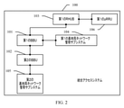
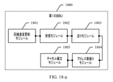
本出願の実施形態において提供される統合アクセスシステムは、単一の事業者および複数の事業者が運用および保守を一緒に実施するシナリオに適用可能である。統合アクセスシステムは、事業者による無線周波数(Radio Frequency、RF)信号ソースの独立した供給をサポートし、将来の大容量および第5世代モバイル通信技術(5th-Generation、5G)シナリオにおけるデジタル信号ソースの供給をサポートし得る。本出願の実施形態において提供される統合アクセスシステムでは、分散されたBBUが使用され、第1のBBUおよび第2のBBUという、少なくとも2つのタイプのBBUが使用される。したがって、各BBUは、BBUのネットワーク管理サブシステムに接続され、それにより、統合アクセスシステム内で分離が実装され得る。図2を参照すると、本出願の実施形態において提供される統合アクセスシステム100は、第1のBBU101、第2のBBU102、第1のデータ交換ユニット103、第1の基地局ネットワーク管理サブシステム104、第2の基地局ネットワーク管理サブシステム105、および第1のpRRU106を含み得る。
The integrated access system provided in embodiments of this application is applicable to scenarios where a single operator and multiple operators perform operations and maintenance together. The integrated access system supports the independent supply of radio frequency (RF) signal sources by operators and is the source of digital signal sources in future high capacity and 5th generation mobile communication technology (5th-Generation, 5G) scenarios. Can support supply. In the integrated access system provided in the embodiments of the present application, distributed BBUs are used, and at least two types of BBUs, a first BBU and a second BBU, are used. Therefore, each BBU may be connected to the BBU's network management subsystem, thereby implementing isolation within the integrated access system. Referring to FIG. 2, the
第1のBBU101は第1のデータ交換ユニット103に接続され、第1のBBU101は第1の基地局ネットワーク管理サブシステム104に接続され、第1のBBU101は第2のBBU102に接続される。
The
第2のBBU102は第2の基地局ネットワーク管理サブシステム105に接続される。
The
第1のpRRU106は第1のデータ交換ユニット103に接続される。
The
本出願のこの実施形態において提供される統合アクセスシステムでは、第1のBBU101および第2のBBU102という、少なくとも2つのタイプのBBUが使用される。第1のBBU101と第2のBBU102は、ファイバーチャネルを通して互いに接続され得る。たとえば、ファイバーチャネルは、CPRIチャネルおよびメディアアクセス制御(Media Access Control、MAC)チャネルを特に含み得る。第1のBBU101は、運用管理(Operate Management、OM)チャネルを通して第1の基地局ネットワーク管理サブシステム104に接続され得る。第1の基地局ネットワーク管理サブシステム104は、第1のBBUを管理するために使用されるネットワーク管理サブシステムである。第1の基地局ネットワーク管理サブシステムは、無線周波数供給機能、第1のデータ交換ユニットに対応するリソースおよび第1のpRRUに対応するリソースをスライシングする機能、ならびに第1のBBUと第2のBBUとの間のサブラック間接続の機能を提供し得る。第2のBBU102は、OMチャネルを通して第2の基地局ネットワーク管理サブシステム105に接続され、事業者は、第2の基地局ネットワーク管理サブシステム105を使用することによってベースバンドリソースを構成および管理し得る。
The integrated access system provided in this embodiment of the present application uses at least two types of BBUs, a
本出願のこの実施形態では、第1のBBU101は、ホストBBUとして働き、建築物中に配設され得、第2のBBU102は、クライアントBBUとして働き、中央機器ルーム中に配設され得る。したがって、ホストBBUおよびクライアントBBUの分散設計が実装され得る。第1のBBU101は第1の基地局ネットワーク管理サブシステム104に接続され、無線周波数リソースは、第1の基地局ネットワーク管理サブシステム104を使用することによって構成および管理され得る。第2のBBU102は第2の基地局ネットワーク管理サブシステム105に接続され、したがって、第2の基地局ネットワーク管理サブシステム105は、事業者の要件に従ってベースバンドリソースを構成し得る。ホストBBUおよびクライアントBBUの分散設計を通して、統合アクセスシステム内の分離が実装され得、事業者の運用および保守は、基地局ネットワーク管理サブシステムのみを使用することによって完了され、それにより、統合アクセスシステムの信頼性および保守性が改善されることが可能である。
In this embodiment of the present application, the
本出願のいくつかの実施形態では、第1のBBUおよび第2のBBUによってそれらのそれぞれの要件に従って使用される必要がある組立て構造のために、第1のBBUは、無線周波数ボード、インターフェースボード、主制御ボード、および直流(Direct Current、DC)を含み得、第2のBBUは、ベースバンドボード、主制御ボード、およびDCを含み得る。第1のBBUのインターフェースボードは、第1のデータ交換ユニット、第2のBBUのベースバンドボードに別々に接続され得る。第1のBBUの主制御ボードは第1の基地局ネットワーク管理サブシステムに接続され得る。第2のBBUの主制御ボードは第2の基地局ネットワーク管理サブシステムに接続され得る。本出願のいくつかの他の実施形態では、ベースバンドボードに加えて、主制御ボード、DC、第2のBBUは、インターフェースボードを含み得る。この場合、第1のBBUのインターフェースボードは第2のBBUのインターフェースボードに接続され得る。 In some embodiments of the present application, the first BBU is a radio frequency board, an interface board, due to the assembly structure that needs to be used by the first BBU and the second BBU according to their respective requirements. , A main control board, and a direct current (DC), and the second BBU may include a baseband board, a main control board, and a DC. The interface board of the first BBU may be separately connected to the baseband board of the first data exchange unit and the second BBU. The main control board of the first BBU may be connected to the first base station network management subsystem. The main control board of the second BBU may be connected to the second base station network management subsystem. In some other embodiments of the present application, in addition to the baseband board, the main control board, DC, second BBU may include an interface board. In this case, the interface board of the first BBU may be connected to the interface board of the second BBU.
本出願のいくつかの実施形態では、第1のBBU101と第1のデータ交換ユニット103は、ファイバーチャネルを通して互いに接続され得ることに留意されたい。ファイバーチャネルは、CPRIチャネルおよびMACチャネルを特に含み得る。第1のデータ交換ユニット103は特にリモートCPRIデータ交換ユニットであり得、これは、後続の実施形態において「RHUB」と呼ばれることもある。RHUBは、第1のBBU101と第1のpRRU106との間の通信を実装し得、第1のpRRU106は無線周波数信号処理機能を実装する。
It should be noted that in some embodiments of the present application, the
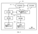
本出願のいくつかの実施形態では、図3を参照すると、統合アクセスシステム100は、第3のBBU107および第3の基地局ネットワーク管理サブシステム108をさらに含む。
In some embodiments of the present application, with reference to FIG. 3, the
第1のBBU101は第3のBBU107に接続される。
The
第3のBBU107は第3の基地局ネットワーク管理サブシステム108に接続される。
The
第1のBBU101と第3のBBU107は、ファイバーチャネルを通して互いに接続され得る。たとえば、ファイバーチャネルは、CPRIチャネルおよびMACチャネルを特に含み得る。第3のBBU107は、OMチャネルを通して第3の基地局ネットワーク管理サブシステム108に接続され得、事業者は、第3の基地局ネットワーク管理サブシステム108を使用することによってベースバンドリソースを構成および管理し得る。
The
本出願の上記の実施形態では、統合アクセスシステム100において、第1のBBU101はホストBBUとして配設され、第2のBBU102と第3のBBU107の両方がクライアントBBUとして配設される。加えて、第2のBBU102および第3のBBU107は、それぞれの基地局ネットワーク管理サブシステムに接続される。たとえば、第2のBBU102は第2の基地局ネットワーク管理サブシステム105に接続され、第3のBBU107は第3の基地局ネットワーク管理サブシステム108に接続される。したがって、複数の事業者がネットワークを一緒に確立し、確立の後にネットワークリソースを共有するシナリオにおいて、それらの異なる事業者は、第2の基地局ネットワーク管理サブシステムおよび第3の基地局ネットワーク管理サブシステムを別々に使用し、それにより、それらの複数の事業者間でアセット分離、運用および保守分離、ならびにサービスアクティブ化およびアップグレード分離を実装し得る。統合アクセスシステム100中に含まれるクライアントBBUは、第2のBBUおよび第3のBBUに限定されなくてよい。複数のクライアントBBUが、ファイバーチャネルを通して統合アクセスシステム中の第1のBBU(すなわち、ホストBBU)に接続されるとき、各クライアントBBUは、1つの基地局ネットワーク管理サブシステムに接続され得る。それらの異なる事業者の各々は、1つの基地局ネットワーク管理サブシステムを使用し得、事業者は分離され、したがって、事業者は互いに干渉しない。
In the above embodiment of the present application, in the
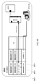
図5は、本出願の実施形態による統合アクセスシステムのシステムアーキテクチャ配備の概略図である。統合アクセスシステム中に1つのホストBBUおよび3つのクライアントBBU(クライアントBBU1、クライアントBBU2、およびクライアントBBU3)が配設される。ホストBBUは、リモートエンドにおいて建築物中に配設され、3つのクライアントBBUは、ローカルエンドにおいて中央機器ルーム中に配設される。ホストBBUは、無線周波数ボードR、インターフェースボード、主制御ボード、およびDCを含む。ホストBBUのインターフェースボードは、3つのクライアントBBUのベースバンドボードに別々に接続され、ホストBBUのインターフェースボードは、CPRIチャネルおよびMACチャネルを通してRHUBにさらに接続される。RHUBは、CPRIチャネルの電気的インターフェース(CPRI-Eインターフェースとも呼ばれる)を通してまたはMACチャネルの電気的インターフェースを通してpRRUに接続される。ホストBBUの主制御ボードは、(図5ではBTS(R)に省略されている)屋内分散ユニファイドネットワーク管理サブシステムに接続される。ホストBBUの無線周波数ボードRはリモート無線ユニット(Remote Radio Unit、RRU)に接続される。たとえば、図5では統合アクセスシステム中に3つのRRUがさらに配設される。3つのRRUは、それぞれRRU-A、RRU-B、およびRRU-Cである。各RRUは、モバイル通信用グローバルシステム(Global System for Mobile Communication、GSM)、ユニバーサルモバイルテレコミュニケーションズシステム(Universal Mobile Telecommunications System、UMTS)、ロングタームエボリューション(Long Term Evolution、LTE)、および符号分割多元接続(Code Division Multiple Access、CDMA)、すなわち、図5に示されている「G/U/L/C」をサポートする。各クライアントBBUは、ベースバンドボードおよび主制御ボードを含む。クライアントBBUのベースバンドボードはホストBBUのインターフェースボードに接続される。クライアントBBUの主制御ボードは、(図5ではBTS(UL)に省略されている)ベースバンドネットワーク管理サブシステムに接続される。たとえば、クライアントBBU1の主制御ボードは、OMチャネルを通して基地局ネットワーク管理サブシステムに接続され、事業者Aは、基地局ネットワーク管理サブシステムを使用することによってベースバンドリソースを構成および管理し得る。クライアントBBU2は、OMチャネルを通して基地局ネットワーク管理サブシステムに接続され、事業者Bは、基地局ネットワーク管理サブシステムを使用することによってベースバンドリソースを構成および管理し得る。クライアントBBU3は、OMチャネルを通して基地局ネットワーク管理サブシステムに接続され、事業者Cは、基地局ネットワーク管理サブシステムを使用することによってベースバンドリソースを構成および管理し得る。本出願のこの実施形態では、複数のクライアントBBUは、複数の事業者が異なるBBUにアクセスするように、ホストBBUにおいて集約されることが可能である。これは、事業者間の運用および保守分離の問題を解決し、将来の大容量展開および5G展開シナリオに適用可能である。 FIG. 5 is a schematic diagram of the system architecture deployment of the integrated access system according to the embodiment of the present application. One host BBU and three client BBUs (client BBU1, client BBU2, and client BBU3) are arranged in the integrated access system. The host BBU is located in the building at the remote end and the three client BBUs are located in the central equipment room at the local end. The host BBU includes a radio frequency board R, an interface board, a main control board, and a DC. The host BBU interface board is separately connected to the baseband boards of the three client BBUs, and the host BBU interface board is further connected to the RHUB through the CPRI and MAC channels. The RHUB is connected to the pRRU through the electrical interface of the CPRI channel (also called the CPRI-E interface) or through the electrical interface of the MAC channel. The main control board of the host BBU is connected to the indoor distributed unified network management subsystem (abbreviated in BTS (R) in FIG. 5). The radio frequency board R of the host BBU is connected to a remote radio unit (Remote Radio Unit, RRU). For example, in FIG. 5, three RRUs are further disposed in the integrated access system. The three RRUs are RRU-A, RRU-B, and RRU-C, respectively. Each RRU is a global system for mobile communication (GSM), universal mobile telecommunications system (Universal Mobile Telecommunication Systems System, UMTS), long term evolution (LongTele), long term evolution (LongTele), and long term evolution (Long). Code Division Multiple Access (CDMA)), that is, "G / U / L / C" shown in FIG. 5 is supported. Each client BBU includes a baseband board and a main control board. The baseband board of the client BBU is connected to the interface board of the host BBU. The main control board of the client BBU is connected to the baseband network management subsystem (abbreviated as BTS (UL) in FIG. 5). For example, the main control board of the client BBU1 is connected to the base station network management subsystem through the OM channel, and the operator A may configure and manage the baseband resources by using the base station network management subsystem. The client BBU2 is connected to the base station network management subsystem through the OM channel, and the operator B can configure and manage the baseband resources by using the base station network management subsystem. The client BBU3 is connected to the base station network management subsystem through the OM channel, and the operator C can configure and manage the baseband resources by using the base station network management subsystem. In this embodiment of the present application, a plurality of client BBUs can be aggregated in a host BBU such that multiple operators access different BBUs. This solves the problem of operational and maintenance separation between operators and is applicable to future large capacity deployment and 5G deployment scenarios.
本出願のいくつかの実施形態では、図5を参照すると、統合アクセスシステムは、第4のBBU109、第2のデータ交換ユニット110、第4の基地局ネットワーク管理サブシステム111、および第2のpRRU112をさらに含む。
In some embodiments of the present application, referring to FIG. 5, the integrated access system is a
第4のBBU109は第2のデータ交換ユニット110に接続され、第4のBBU109は第4の基地局ネットワーク管理サブシステム111に接続され、第4のBBU109は第2のBBU102に接続される。
The
第2のpRRU112は第2のデータ交換ユニット110に接続される。
The
統合アクセスシステムにおいて、第1のBBU101と第4のBBU109の両方がホストBBUとして働き得る。たとえば、第1のBBU101および第4のBBU109は、異なる建築物中に配設され得る。第1のBBU101および第4のBBU109は、異なるファイバーチャネルを通して第2のBBU102に別々に接続され得る。第2のBBU102は、クライアントBBUと複数のホストBBUとの間のサブラック間接続をサポートするために、中央機器ルーム中に配設され得、それにより、1つの中央機器ルームは複数の周囲の建築物をカバーする。
In the integrated access system, both the
本出願の上記の実施形態では、複数の事業者が統合アクセスシステムにアクセスする必要がある場合、各事業者は、1つのクライアントBBUおよび1つの基地局ネットワーク管理サブシステムを使用することができることに留意されたい。複数のホストBBUがあるとき、各ホストBBUはすべてのクライアントBBUに接続されることが可能である。接続方式については、第1のBBU101および第4のBBU109が第2のBBU102に別々に接続される方式を参照されたい。
In the above embodiment of the present application, if multiple operators need to access the integrated access system, each operator may use one client BBU and one base station network management subsystem. Please note. When there are multiple host BBUs, each host BBU can be connected to all client BBUs. For the connection method, refer to the method in which the
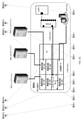
図6A、図6B、図6C、および図6Dは、本出願の実施形態による別の統合アクセスシステムのシステムアーキテクチャ配備の概略図である。統合アクセスシステム中に3つのホストBBUおよび3つのクライアントBBU(クライアントBBU1、クライアントBBU2、およびクライアントBBU3)が配設される。ホストBBU0は、リモートエンドにおいて建築物0中に配設され、ホストBBU1は、リモートエンドにおいて建築物1中に配設され、ホストBBU2は、リモートエンドにおいて建築物2中に配設される。3つのクライアントBBUは、ローカルエンドにおいて中央機器ルーム中に配設される。建築物0中に配設されたホストBBUが例として使用される。ホストBBUは、無線周波数ボードR、インターフェースボード、主制御ボード、およびDCを含む。ホストBBUのインターフェースボードは、3つのクライアントBBUのベースバンドボードに別々に接続され、ホストBBUのインターフェースボードは、CPRIチャネルおよびMACチャネルを通してRHUBにさらに接続される。RHUBは、CPRI-EインターフェースまたはMACチャネルの電気的インターフェースを通してpRRUに接続される。ホストBBUの主制御ボードは、(図5ではBTS(R)に省略されている)屋内分散ユニファイドネットワーク管理サブシステムに接続される。ホストBBUの無線周波数ボードRはRRUに接続される。たとえば、図6では統合アクセスシステム中に3つのRRUがさらに配設される。3つのRRUは、それぞれRRU-A、RRU-B、およびRRU-Cである。図6に示されているように、統合アクセスシステム中に複数のホストBBUまたは複数のクライアントBBUが配設され得る。したがって、クライアントBBUと複数のホストBBUとの間のサブラック間接続がサポートされ得、それにより、1つの中央機器ルームは複数の周囲建築物をカバーする。
6A, 6B, 6C, and 6D are schematics of system architecture deployment of another integrated access system according to embodiments of the present application. Three host BBUs and three client BBUs (client BBU1, client BBU2, and client BBU3) are arranged in the integrated access system. The host BBU0 is disposed in the building 0 at the remote end, the host BBU1 is disposed in the
本出願の実施形態において提供される統合アクセスシステムの組立て構造の説明から、統合アクセスシステムは、第1のBBUおよび第2のBBUという、2つのタイプのBBUを含むことがわかる。第1のBBUと第2のBBUは、互いに通信するために接続される。加えて、第1のBBUは第1の基地局ネットワーク管理サブシステムに接続され、第2のBBUは第2の基地局ネットワーク管理サブシステムに接続される。したがって、第1のBBUの無線周波数リソースは、第1の基地局ネットワーク管理サブシステムを使用することによって別々に構成および管理され得、第2のBBUのベースバンドリソースは、第2の基地局ネットワーク管理サブシステムを使用することによって別々に構成および管理され得る。このようにして、無線周波数リソースおよびベースバンドリソースは独立して管理されることが可能であり、統合アクセスシステムの信頼性および保守性は大幅に改善される。 From the description of the assembly structure of the integrated access system provided in the embodiments of the present application, it can be seen that the integrated access system includes two types of BBUs, a first BBU and a second BBU. The first BBU and the second BBU are connected to communicate with each other. In addition, the first BBU is connected to the first base station network management subsystem and the second BBU is connected to the second base station network management subsystem. Therefore, the radio frequency resources of the first BBU can be separately configured and managed by using the first base station network management subsystem, and the baseband resources of the second BBU are the second base station network. It can be configured and managed separately by using a management subsystem. In this way, radio frequency resources and baseband resources can be managed independently, greatly improving the reliability and maintainability of the integrated access system.
本出願の実施形態において提供される統合アクセスシステムについて、上記の実施形態において説明された。統合アクセスシステムに基づく構成方法について以下で説明される。本方法は、統合アクセスシステムにおいてクロック構成を実装するために使用され得る。本出願の実施形態において提供される構成方法は統合アクセスシステムに適用可能である。図2に示されているように、統合アクセスシステムは、第1のBBUおよび第2のBBUを含む。第1のBBUは第2のBBUに接続される。たとえば、第1のBBUと第2のBBUは、ファイバーチャネルを通して互いに接続される。図7に示されているように、本出願のこの実施形態において提供される構成方法は以下のステップを含み得る。 The integrated access system provided in embodiments of this application has been described in the embodiments described above. The configuration method based on the integrated access system will be described below. The method can be used to implement a clock configuration in an integrated access system. The configuration methods provided in embodiments of this application are applicable to integrated access systems. As shown in FIG. 2, the integrated access system includes a first BBU and a second BBU. The first BBU is connected to the second BBU. For example, the first BBU and the second BBU are connected to each other through Fiber Channel. As shown in FIG. 7, the configuration method provided in this embodiment of the present application may include the following steps.
701.第1のBBUが第1のクロック同期情報を取得し、第1のクロック同期情報は、第1のBBUのクロック周波数およびクロック位相を含む。 701. The first BBU acquires the first clock synchronization information, and the first clock synchronization information includes the clock frequency and the clock phase of the first BBU.
702.第1のBBUが第1のクロック同期情報を第2のBBUに送る。 702. The first BBU sends the first clock synchronization information to the second BBU.
第1のBBUはホストBBUとして働き、第1のBBUは、第2のBBUに基準クロックを提供する必要がある。第2のBBUは、第1のBBUによって提供される基準クロックに基づいて第2のBBUのローカルクロックを補正し、それにより、BBU間でサブラック間クロック同期を実装し得る。第1のBBUは、ローカルクロックソースから第1のBBUのクロック周波数およびクロック位相を取得し得、次いで、第1のBBUは、第1のクロック同期情報を第2のBBUに送る。加えて、第1のBBUは、クロックサーバと対話し、クロックサーバからクロック周波数およびクロック位相を取得し得る。次いで、第1のBBUは、クロック周波数およびクロック位相に基づいて第1のBBUのローカルクロックソースを補正し、たとえば、位相ロックループ(Phase-Locked Loop、PLL)を使用することによってフィードバック制御を実施し、クロックサーバによって提供される外部基準信号を使用することによってループ中のクロック信号の周波数および位相を制御し得る。第1のBBUと第2のBBUは、ファイバーチャネルを通して互いに接続され得、ファイバーチャネルは、CPRIチャネルおよびMACチャネルを特に含み得る。第1のBBUは、CPRIフレームに第1のクロック同期情報を追加し、次いで、CPRIチャネルを通してCPRIフレームを第2のBBUに送り得る。代替として、第1のBBUは、MACチャネルに第1のクロック同期情報を追加し、次いで、MACチャネルを通してMACフレームを第2のBBUに送り得る。 The first BBU acts as a host BBU and the first BBU needs to provide a reference clock to the second BBU. The second BBU may correct the local clock of the second BBU based on the reference clock provided by the first BBU, thereby implementing sub-black clock synchronization between the BBUs. The first BBU may obtain the clock frequency and clock phase of the first BBU from the local clock source, and then the first BBU sends the first clock synchronization information to the second BBU. In addition, the first BBU may interact with the clock server to obtain the clock frequency and clock phase from the clock server. The first BBU then corrects the local clock source of the first BBU based on the clock frequency and clock phase and performs feedback control, for example, by using a phase-locked loop (PLL). However, the frequency and phase of the clock signal in the loop can be controlled by using an external reference signal provided by the clock server. The first BBU and the second BBU may be connected to each other through Fiber Channel, which may specifically include CPRI channels and MAC channels. The first BBU may add the first clock synchronization information to the CPRI frame and then send the CPRI frame to the second BBU through the CPRI channel. Alternatively, the first BBU may add the first clock synchronization information to the MAC channel and then send the MAC frame to the second BBU through the MAC channel.
本出願のいくつかの実施形態では、図3を参照すると、統合アクセスシステムは第3のBBUをさらに含み、第3のBBUは第1のBBUに接続される。この実装シナリオでは、統合アクセスシステムに基づく構成方法は以下のステップをさらに含み得る。 In some embodiments of the present application, referring to FIG. 3, the integrated access system further comprises a third BBU, the third BBU being connected to the first BBU. In this implementation scenario, the configuration method based on the integrated access system may further include the following steps:
A1.第1のBBUが第1のクロック同期情報を第3のBBUに送る。 A1. The first BBU sends the first clock synchronization information to the third BBU.
第1のBBUがホストBBUとして2つのクライアントBBUに接続されたとき、第1のBBUが第1のクロック同期情報を取得した後に、第1のBBUは、第1のクロック同期情報を第2のBBUおよび第3のBBUに別々に送り得、したがって、第3のBBUは、クライアントBBUとして、第1のBBUの第1のクロック同期情報を受信することもできる。第3のBBUは、第1のクロック同期情報を使用して第3のBBUのローカルクロックソースを補正し、それにより、BBU間でサブラック間クロック同期を実装し得る。 When the first BBU is connected to the two client BBUs as the host BBU, after the first BBU acquires the first clock synchronization information, the first BBU transfers the first clock synchronization information to the second. It can be sent separately to the BBU and the third BBU, and thus the third BBU can also receive the first clock synchronization information of the first BBU as the client BBU. The third BBU may use the first clock synchronization information to correct the local clock source of the third BBU, thereby implementing clock synchronization between subblacks between BBUs.
本出願の上記の実施形態では、クロック同期処理は第1のBBU側から説明されていることに留意されたい。第4のBBUによって実施される方法は、第1のBBUによって実施される方法と同様であることが理解されよう。第4のBBUは第2のクロック同期情報を生成し得、次いで、第4のBBUは第2のクロック同期情報を第2のBBUに送る。第2のクロック同期情報は、第4のBBUのクロック周波数およびクロック位相を含む。 It should be noted that in the above embodiment of the present application, the clock synchronization process is described from the first BBU side. It will be appreciated that the method performed by the fourth BBU is similar to the method performed by the first BBU. The fourth BBU may generate the second clock synchronization information, and then the fourth BBU sends the second clock synchronization information to the second BBU. The second clock synchronization information includes the clock frequency and clock phase of the fourth BBU.
図7に示されているクロック構成処理の例示的な説明から、第1のBBUは、第1のクロック同期情報を第2のBBUに送り得、したがって、第2のBBUは、第1のクロック同期情報に基づいて第2のBBUのローカルクロック情報を構成し、それにより、BBU間でサブラック間クロック同期を実装することができることがわかる。たとえば、BBUモードが構成される。基地局ネットワーク管理サブシステムのOMチャネルを通して、第1のBBUはホストBBUモードとして構成され得、第2のBBUはクライアントBBUモードとして構成され得る。複数のBBUのサブラック間集約がサポートされ、したがって、複数の事業者は異なるBBUにアクセスし、それにより、事業者間の運用および保守分離の問題を解決し、BBUアクセスに基づく将来の大容量展開を実装する。加えて、本出願のこの実施形態では、複数のホストBBUと複数のクライアントBBUとの間のサブラック間接続がサポートされ、それにより、1つの中央機器ルームは複数の周囲の建築物をカバーする。 From the exemplary description of the clock configuration process shown in FIG. 7, the first BBU may send the first clock synchronization information to the second BBU, thus the second BBU is the first clock. It can be seen that the local clock information of the second BBU can be configured based on the synchronization information, whereby the clock synchronization between sub-blacks can be implemented between the BBUs. For example, BBU mode is configured. Through the OM channel of the base station network management subsystem, the first BBU may be configured as the host BBU mode and the second BBU may be configured as the client BBU mode. Multi-submarine aggregation of multiple BBUs is supported, thus allowing multiple operators to access different BBUs, thereby resolving operational and maintenance separation issues between operators and future large capacity based on BBU access. Implement the deployment. In addition, in this embodiment of the present application, subblack connections between multiple host BBUs and multiple client BBUs are supported, whereby one central equipment room covers multiple surrounding buildings. ..
統合アクセスシステムに基づく構成方法について、上記の実施形態では第1のBBU側から説明されており、本出願の実施形態において提供される統合アクセスシステムに基づく構成方法について、以下では第2のBBU側から説明される。本方法は、統合アクセスシステムにおいてクロック構成を実装するために使用され得る。本出願の実施形態において提供される構成方法は統合アクセスシステムに適用可能である。図2に示されているように、統合アクセスシステムは、第1のBBUおよび第2のBBUを含む。第1のBBUは第2のBBUに接続される。たとえば、第1のBBUと第2のBBUは、ファイバーチャネルを通して互いに接続される。図8に示されているように、本出願のこの実施形態において提供される構成方法は以下のステップを含み得る。 The configuration method based on the integrated access system is described from the first BBU side in the above embodiment, and the configuration method based on the integrated access system provided in the embodiment of the present application is described below from the second BBU side. Explained from. The method can be used to implement a clock configuration in an integrated access system. The configuration methods provided in embodiments of this application are applicable to integrated access systems. As shown in FIG. 2, the integrated access system includes a first BBU and a second BBU. The first BBU is connected to the second BBU. For example, the first BBU and the second BBU are connected to each other through Fiber Channel. As shown in FIG. 8, the configuration method provided in this embodiment of the present application may include the following steps.
801.第2のBBUが、第1のBBUによって送られた第1のクロック同期情報を受信し、第1のクロック同期情報は、第1のBBUのクロック周波数およびクロック位相を含む。 801. The second BBU receives the first clock synchronization information sent by the first BBU, and the first clock synchronization information includes the clock frequency and the clock phase of the first BBU.
第2のBBUと第1のBBUは、ファイバーチャネルを通して互いに接続される。第1のBBUは第1のクロック同期情報を第2のBBUに送る。第2のBBUは、ファイバーチャネルを通して第1のクロック同期情報を受信し得、第2のBBUは、第1のクロック同期情報をパースして第1のBBUのクロック周波数およびクロック位相を取得し得る。 The second BBU and the first BBU are connected to each other through Fiber Channel. The first BBU sends the first clock synchronization information to the second BBU. The second BBU may receive the first clock synchronization information through Fiber Channel, and the second BBU may parse the first clock synchronization information to obtain the clock frequency and clock phase of the first BBU. ..
802.第2のBBUが、第1のクロック同期情報に基づいて第2のBBUのローカルクロック情報を構成する。 802. The second BBU constitutes the local clock information of the second BBU based on the first clock synchronization information.
第2のBBUが第1のBBUから第1のクロック同期情報を取得した後に、第2のBBUは、基準クロックソースとして第1のBBUのクロック周波数およびクロック位相を使用することによって第2のBBUのローカルクロック情報を補正する。たとえば、第2のBBUは、PLLを使用することによってフィードバック制御を実施し、第1のBBUによって提供される外部基準信号を使用することによってループ中のクロック信号の周波数および位相を制御し得る。 After the second BBU acquires the first clock synchronization information from the first BBU, the second BBU uses the clock frequency and clock phase of the first BBU as the reference clock source to obtain the second BBU. Correct the local clock information of. For example, the second BBU may perform feedback control by using the PLL and may control the frequency and phase of the clock signal in the loop by using the external reference signal provided by the first BBU.
本出願のいくつかの実施形態では、統合アクセスシステムは第4のBBUをさらに含み、第4のBBUは第2のBBUに接続される。第4のBBUによって実施される方法について、本出願の上記の実施形態において説明されている。第4のBBUは第2のクロック同期情報を生成し得、次いで、第4のBBUは第2のクロック同期情報を第2のBBUに送る。第2のクロック同期情報は、第4のBBUのクロック周波数およびクロック位相を含む。このシナリオでは、上記のステップに加えて、本出願のこの実施形態における提供される構成方法は以下のステップを含む。 In some embodiments of the present application, the integrated access system further comprises a fourth BBU, the fourth BBU being connected to a second BBU. The method carried out by the fourth BBU is described in the above embodiment of the present application. The fourth BBU may generate the second clock synchronization information, and then the fourth BBU sends the second clock synchronization information to the second BBU. The second clock synchronization information includes the clock frequency and clock phase of the fourth BBU. In this scenario, in addition to the steps above, the configuration method provided in this embodiment of the present application comprises the following steps:
B1.第2のBBUが、第4のBBUによって送られた第2のクロック同期情報を受信し、第2のクロック同期情報は、第4のBBUのクロック周波数およびクロック位相を含む。 B1. The second BBU receives the second clock synchronization information sent by the fourth BBU, and the second clock synchronization information includes the clock frequency and clock phase of the fourth BBU.
第1のクロック同期情報を受信することに加えて、第2のBBUは、第4のBBUの第2のクロック同期情報を受信する。第2のBBUは、第2のクロック同期情報をパースして、第4のBBUのクロック周波数およびクロック位相を取得し得る。第2のBBUと第4のBBUの両方がホストBBUとして働くとき、第2のBBUおよび第4のBBUは、クライアントBBUとして働いている第2のBBUにクロック同期情報を別々に送り得、第2のBBUは、第1のBBUのクロック周波数およびクロック位相、ならびに第4のBBUのクロック周波数およびクロック位相を別々に取得し得る。 In addition to receiving the first clock synchronization information, the second BBU receives the second clock synchronization information of the fourth BBU. The second BBU may parse the second clock synchronization information to obtain the clock frequency and clock phase of the fourth BBU. When both the second BBU and the fourth BBU act as the host BBU, the second BBU and the fourth BBU may send clock synchronization information separately to the second BBU acting as the client BBU, the second. The BBU of 2 may acquire the clock frequency and clock phase of the first BBU separately, and the clock frequency and clock phase of the fourth BBU.
ステップB1が実施される実装シナリオでは、第2のBBUが第1のクロック同期情報に基づいて第2のBBUのローカルクロック情報を構成するステップ802は以下のステップを含む。
In the implementation scenario in which step B1 is performed,
C1.第2のBBUが、第1のクロック同期情報および第2のクロック同期情報に基づいて第2のBBUのローカルクロック情報を構成する。 C1. The second BBU constitutes the local clock information of the second BBU based on the first clock synchronization information and the second clock synchronization information.
第2のBBUが第1のクロック同期情報および第2のクロック同期情報を別々に取得するとき、第2のBBUは、第1のBBUのクロック周波数およびクロック位相、ならびに第4のBBUのクロック周波数およびクロック位相を取得し得る。第2のBBUは、これら2つのホストBBUのクロック同期情報を使用することによって第2のBBUのローカルクロック情報を判定する。第2のBBUは、複数の方式でローカルクロック情報を構成し得る。たとえば、第2のBBUが第1のクロック同期情報および第2のクロック同期情報に基づいて第2のBBUのローカルクロック情報を構成するステップC1は以下のステップを含む。 When the second BBU acquires the first clock synchronization information and the second clock synchronization information separately, the second BBU is the clock frequency and clock phase of the first BBU, and the clock frequency of the fourth BBU. And the clock phase can be obtained. The second BBU determines the local clock information of the second BBU by using the clock synchronization information of these two host BBUs. The second BBU may configure local clock information in a plurality of ways. For example, step C1 in which the second BBU configures the local clock information of the second BBU based on the first clock synchronization information and the second clock synchronization information includes the following steps.
C11.第2のBBUが、第1のクロック同期情報および第2のクロック同期情報から、より高いクロック品質をもつクロック同期情報を選択し、より高いクロック品質をもつクロック同期情報に基づいて第2のBBUのローカルクロック情報を構成する。 C11. The second BBU selects the clock synchronization information having a higher clock quality from the first clock synchronization information and the second clock synchronization information, and the second BBU is based on the clock synchronization information having a higher clock quality. Configure local clock information for.
第2のBBUは、第1のBBUおよび第4のBBUによって第2のBBUに別々に送られたクロック同期情報から、より高いクロック品質をもつクロック同期情報を選択し、より高いクロック品質をもつクロック同期情報に基づいて第2のBBUのローカルクロック情報を構成し得る。クロック品質は、クロックソースのクロック信号品質である。クロック品質は、クロックソースの安定性によって測定されるか、クロックソースの精度によって測定されるか、クロックソースの安定性および精度によって測定され得る。クロックソースは、安定性および精度という、2つの重要なインジケータを有する。精度は、公称値からの偏差を指し、安定性は、外部ファクタが変化するにつれて生成される変化量を指す。たとえば、より高い安定性および精度は、クロックソースのより高いクロック品質を示す。本出願のいくつかの実施形態では、第2のBBUが第1のクロック同期情報および第2のクロック同期情報に基づいて第2のBBUのローカルクロック情報を構成するとき、上記の例示的な説明は限定のために意図されておらず、第2のBBUは、第1のクロック同期情報および第2のクロック同期情報から、より高い安定性をもつクロック同期情報を選択し、より高い安定性をもつクロック同期情報に基づいて第2のBBUのローカルクロック情報を構成し得る。より高い安定性をもつクロック同期情報は第2のBBUのローカルクロック情報として選択され、それにより、第2のBBUのクロック安定性は保証され得る。 The second BBU selects the clock synchronization information having higher clock quality from the clock synchronization information sent separately to the second BBU by the first BBU and the fourth BBU, and has higher clock quality. The local clock information of the second BBU may be configured based on the clock synchronization information. The clock quality is the clock signal quality of the clock source. Clock quality can be measured by the stability of the clock source, by the accuracy of the clock source, or by the stability and accuracy of the clock source. The clock source has two important indicators: stability and accuracy. Accuracy refers to the deviation from the nominal value, and stability refers to the amount of change that is generated as the external factor changes. For example, higher stability and accuracy indicate higher clock quality for a clock source. In some embodiments of the present application, when the second BBU configures the local clock information of the second BBU based on the first clock synchronization information and the second clock synchronization information, the above exemplary description. Is not intended for limitation, the second BBU selects the clock synchronization information with higher stability from the first clock synchronization information and the second clock synchronization information to obtain higher stability. The local clock information of the second BBU can be configured based on the clock synchronization information of the second BBU. The clock synchronization information with higher stability is selected as the local clock information of the second BBU, whereby the clock stability of the second BBU can be guaranteed.
図8に示されているクロック構成処理の例示的な説明から、第1のBBUは、第1のクロック同期情報を第2のBBUに送り得、したがって、第2のBBUは、第1のクロック同期情報に基づいて第2のBBUのローカルクロック情報を構成し、それにより、BBU間でサブラック間クロック同期を実装することができることがわかる。 From the exemplary description of the clock configuration process shown in FIG. 8, the first BBU may send the first clock synchronization information to the second BBU, thus the second BBU is the first clock. It can be seen that the local clock information of the second BBU can be configured based on the synchronization information, whereby the clock synchronization between sub-blacks can be implemented between the BBUs.
図7および図8に示されているクロック構成処理について、例を使用することによって以下で説明される。図4を参照すると、説明のための例としてホストBBUとクライアントBBUとの間のクロック同期が使用される。本出願のこの実施形態では、パネルCPRI相互接続に基づくサブラック間クロックソフト同期が実装され得る。具体的には、ホストBBUは、CPRIフレームまたはMACフレームを使用することによってサブラック間ファイバーを通してホストBBUのクロック周波数および位相情報をクライアントBBUに転送する。BBUのためのモードが最初に選択される。第1のBBUのモードはホスト(Host)BBUモードとして構成され、第2のBBUのモードはクライアント(Client)BBUモードとして構成される。本出願のこの実施形態において提供される統合アクセスシステムでは、BBUは、基地局ネットワーク管理サブシステムのOMチャネルを通してホストBBUまたはクライアントBBUとして構成され得る。 The clock configuration process shown in FIGS. 7 and 8 will be described below by using an example. Referring to FIG. 4, clock synchronization between the host BBU and the client BBU is used as an example for illustration. In this embodiment of the present application, clock soft synchronization between sub-blacks based on panel CPRI interconnection may be implemented. Specifically, the host BBU transfers the clock frequency and phase information of the host BBU to the client BBU through the subblack fiber by using the CPRI frame or the MAC frame. The mode for BBU is selected first. The first BBU mode is configured as the Host BBU mode and the second BBU mode is configured as the Client BBU mode. In the integrated access system provided in this embodiment of the present application, the BBU may be configured as a host BBU or a client BBU through the OM channel of the base station network management subsystem.
ホストBBUを構成するために屋内分散ユニファイドネットワーク管理サブシステムが使用される。ホストBBUは、ホストBBUのローカルクロックソースからクロックを取得し、相互接続ファイバー(すなわち、CPRIチャネルまたはMACチャネル)を通してクロック同期情報を他のクライアントBBUにブロードキャストする。BBUがクライアントBBUとして構成されたとき、クライアントBBUは、相互接続ファイバー(すなわち、CPRIチャネルまたはMACチャネル)からクロックを復元する。クライアントBBUは、クライアントBBUの基準クロックソースとして、復元されたクロックを使用して、サブラック間クロック同期を実装する。 An indoor distributed unified network management subsystem is used to configure the host BBU. The host BBU obtains the clock from the host BBU's local clock source and broadcasts the clock synchronization information to other client BBUs through the interconnect fiber (ie, CPRI channel or MAC channel). When the BBU is configured as a client BBU, the client BBU restores the clock from the interconnect fiber (ie, CPRI channel or MAC channel). The client BBU uses the restored clock as a reference clock source for the client BBU to implement clock synchronization between subblacks.
本出願の実施形態において提供される統合アクセスシステムについて、上記の実施形態において説明された。統合アクセスシステムに基づく構成方法について以下で説明される。本方法は、統合アクセスシステムにおいて上位レイヤ通信チャネルを確立するために使用され得る。本出願の実施形態では、上位レイヤ通信チャネルは、手動構成なしにホストBBUとクライアントBBUとの間で自動的に確立され、それにより、手動コストが低減され、エラー確率が減少され得る。本出願の実施形態において提供される構成方法は統合アクセスシステムに適用可能である。図2に示されているように、統合アクセスシステムは、第1のBBUおよび第2のBBUを含む。第1のBBUは第2のBBUに接続される。たとえば、第1のBBUと第2のBBUは、ファイバーチャネルを通して互いに接続される。図9に示されているように、本出願のこの実施形態において提供される構成方法は以下のステップを含み得る。 The integrated access system provided in embodiments of this application has been described in the embodiments described above. The configuration method based on the integrated access system will be described below. This method can be used to establish a higher layer communication channel in an integrated access system. In embodiments of the present application, higher layer communication channels are automatically established between the host BBU and the client BBU without manual configuration, which can reduce manual costs and error probabilities. The configuration methods provided in embodiments of this application are applicable to integrated access systems. As shown in FIG. 2, the integrated access system includes a first BBU and a second BBU. The first BBU is connected to the second BBU. For example, the first BBU and the second BBU are connected to each other through Fiber Channel. As shown in FIG. 9, the configuration method provided in this embodiment of the present application may include the following steps.
901.第1のBBUが、第1の回線速度を更新し、各更新の後に、更新された第1の回線速度においてデータフレームを第2のBBUに送る。 901. The first BBU updates the first line speed and after each update sends a data frame to the second BBU at the updated first line speed.
第1のBBUによって使用される回線速度は「第1の回線速度」として定義され、第2のBBUによって使用される回線速度は「第2の回線速度」として定義される。回線速度は、物理レイヤチャネルの回線速度である。第1のBBUは、第1の回線速度を絶えず更新し、すなわち、第1のBBUは、第1の回線速度の速度値を更新し、各更新の後に、更新された第1の回線速度においてデータフレームを第2のBBUに送る。同様に、第2のBBUは、第2の回線速度を絶えず更新し、すなわち、第2のBBUは、第2の回線速度の速度値を更新し、各更新の後に、第2の回線速度に基づく更新されたデータフレームを第1のBBUに送る。 The line speed used by the first BBU is defined as the "first line speed" and the line speed used by the second BBU is defined as the "second line speed". The line speed is the line speed of the physical layer channel. The first BBU constantly updates the first line speed, i.e., the first BBU updates the speed value of the first line speed, and after each update, at the updated first line speed. Send the data frame to the second BBU. Similarly, the second BBU constantly updates the second line speed, i.e., the second BBU updates the speed value of the second line speed, and after each update, to the second line speed. Send the updated data frame based on to the first BBU.
本出願のいくつかの実施形態では、第1のBBUが第1の回線速度を更新するステップ901は以下のステップを含む。
In some embodiments of the present application,
D1.第1のBBUが、第1の期間に基づいて第1の回線速度を更新し、第1の期間と第2の期間は異なる期間であり、第2の期間は、第2のBBUが第2の回線速度をそれに基づいて更新する期間である。 D1. The first BBU updates the first line speed based on the first period, the first period and the second period are different periods, and in the second period, the second BBU is the second. It is a period to update the line speed of.
第1のBBUと第2のBBUの両方が、それぞれの期間に基づいてそれぞれの回線速度値を更新し、第1の期間と第2の期間は異なる期間である。したがって、第1の期間および第2の期間中に、より長い期間およびより短い期間が必ずある。第1のBBUおよび第2のBBUは、第1のBBUと第2のBBUとの間でブラインド回線速度マッチングを試みるために、それぞれの回線速度を周期的に更新し、それにより、手動構成を実施するために手動リソースを占有することなしに回線速度オートネゴシエーションを実装する。 Both the first BBU and the second BBU update their line speed values based on their respective periods, with the first and second periods being different periods. Therefore, there will always be longer and shorter periods during the first and second periods. The first BBU and the second BBU periodically update their respective line speeds in order to attempt blind line speed matching between the first BBU and the second BBU, thereby providing manual configuration. Implement line speed auto-negotiation without occupying manual resources to implement.
902.第2のBBUが第2の回線速度を更新する各時間の後に、第1のBBUが、更新された第2の回線速度において第2のBBUによって送られたデータフレームを受信する。 902. After each time the second BBU updates the second line speed, the first BBU receives the data frame sent by the second BBU at the updated second line speed.
各更新の後に、第2のBBUは、第2の回線速度に基づく更新されたデータフレームを第1のBBUに送る。したがって、第2のBBUは、第2の回線速度に基づくデータフレームをファイバーチャネルを通して第1のBBUに絶えず送り、第1のBBUは、第2の回線速度に基づき、第2のBBUによって絶えず送られるデータフレームを受信する。第1のBBUは、送られる第1の回線速度が、受信される第2の回線速度に等しいかどうかを判定する必要がある。これら2つの回線速度が等しい場合、後続のステップ903がトリガされるか、またはこれら2つの回線速度が等しくない場合、ステップ901およびステップ902が実施され続ける。
After each update, the second BBU sends an updated data frame based on the second line speed to the first BBU. Therefore, the second BBU constantly sends data frames based on the second line speed to the first BBU through Fiber Channel, and the first BBU is constantly sent by the second BBU based on the second line speed. Receive the data frame to be received. The first BBU needs to determine if the first line speed sent is equal to the second line speed received. If these two line speeds are equal, the
903.第1の回線速度が第2の回線速度に等しいとき、第1のBBUが、第1の回線速度において第1のBBUのネットワーキング関係情報を第2のBBUに送り、第2の回線速度において第2のBBUによって送られた第2のBBUのネットワーキング関係情報を受信する。 903. When the first line speed is equal to the second line speed, the first BBU sends the networking related information of the first BBU to the second BBU at the first line speed, and the second line speed at the second line speed. Receives the networking related information of the second BBU sent by the second BBU.
第1のBBUによって送られる第1の回線速度が、受信される第2の回線速度に等しいとき、それは、第1のBBUと第2のBBUとの間の速度ネゴシエーションが完了したことを示す。この場合、第1のBBUは、第1の回線速度において第1のBBUのネットワーキング関係情報を第2のBBUに送り、第2の回線速度において第2のBBUによって送られた第2のBBUのネットワーキング関係情報を受信し得る。第1のBBUのネットワーキング関係情報は、第1のBBUに接続されたBBUの量、および第1のBBUに接続されたインターフェースボード上のポートである。第2のBBUのネットワーキング関係情報は、第2のBBUに接続されたBBUの量、および第2のBBUに接続されたベースバンドボードまたはインターフェースボード上のポートである。第1のBBUと第2のBBUは、それぞれのネットワーキング関係情報を交換し、したがって、第1のBBUおよび第2のBBUはそれぞれ、BBUのネットワーキング関係情報に基づいてネットワークトポロジー図を生成することができる。複数のBBU間のサブラック間接続関係は、ネットワークトポロジー図を使用することによって好都合に取得され得る。 When the first line speed sent by the first BBU is equal to the second line speed received, it indicates that the speed negotiation between the first BBU and the second BBU has been completed. In this case, the first BBU sends the networking related information of the first BBU to the second BBU at the first line speed, and the second BBU sent by the second BBU at the second line speed. Can receive networking related information. The networking related information of the first BBU is the amount of BBU connected to the first BBU, and the port on the interface board connected to the first BBU. The networking related information of the second BBU is the amount of BBU connected to the second BBU and the port on the baseband board or interface board connected to the second BBU. The first BBU and the second BBU exchange their respective networking relational information, so that the first BBU and the second BBU can each generate a network topology diagram based on the BBU's networking relational information. can. The connection relationship between sub-blacks between a plurality of BBUs can be conveniently obtained by using a network topology diagram.
本出願のいくつかの実施形態では、第1の回線速度が第2の回線速度に等しいとき、ステップ903に加えて、本出願のこの実施形態において提供される方法は以下のステップを含み得る。
In some embodiments of the present application, when the first line speed is equal to the second line speed, in addition to
E1.第1のBBUが、第1の回線速度において第1のBBUの回線速度能力情報を第2のBBUに送る。 E1. The first BBU sends the line speed capability information of the first BBU to the second BBU at the first line speed.
E2.第1のBBUが、第2の回線速度において第2のBBUによって送られた第2のBBUの回線速度能力情報を受信する。 E2. The first BBU receives the line speed capability information of the second BBU sent by the second BBU at the second line speed.
E3.第1のBBUが、第1のBBUの回線速度能力情報および第2のBBUの回線速度能力情報に基づいて、第1のBBUと第2のBBUとの間で物理レイヤ通信を実施するために使用される回線速度を判定する。 E3. In order for the first BBU to carry out physical layer communication between the first BBU and the second BBU based on the line speed capacity information of the first BBU and the line speed capacity information of the second BBU. Determine the line speed used.
回線速度能力情報は、物理レイヤチャネル上でのBBUの最大送信能力である。第1のBBUおよび第2のBBUは、それぞれの回線速度能力情報を交換し、次いで、第1のBBUの回線速度能力情報および第2のBBUの回線速度能力情報に基づいて、第1のBBUと第2のBBUとの間で物理レイヤ通信を実施するために使用される回線速度を判定する。たとえば、手動構成を実施するために手動リソースを占有することなしに回線速度オートネゴシエーションを実装するために、第1のBBUと第2のBBUとの間で物理レイヤ通信を実施するために使用される回線速度として、第1のBBUの回線速度能力情報と第2のBBUの回線速度能力情報の交差セット中の最大回線速度が選択され得る。 The line speed capability information is the maximum transmission capability of the BBU on the physical layer channel. The first BBU and the second BBU exchange their respective line speed capacity information, and then the first BBU is based on the line speed capacity information of the first BBU and the line speed capacity information of the second BBU. Determines the line speed used to perform physical layer communication between the and the second BBU. For example, used to perform physical layer communication between a first BBU and a second BBU to implement line speed auto-negotiation without occupying manual resources to perform manual configuration. As the line speed, the maximum line speed in the intersection set of the line speed capacity information of the first BBU and the line speed capacity information of the second BBU can be selected.
904.第1のBBUが、第2のBBUのネットワーキング関係情報に基づいて第2のBBUに通信アドレスを割り振り、第1のBBUの通信アドレスを第2のBBUに送る。 904. The first BBU allocates a communication address to the second BBU based on the networking-related information of the second BBU, and sends the communication address of the first BBU to the second BBU.
本出願のこの実施形態では、第1のBBUと第2のBBUがそれぞれのネットワーキング関係情報を交換した後に、第1のBBUは、第2のBBUのネットワーキング関係情報に基づいて第2のBBUに通信アドレスを割り振り、第1のBBUの通信アドレスを第2のBBUに送り、したがって、第2のBBUは、第1のBBUの通信アドレスを取得することができる。通信アドレスは、BBUのロケーションのロケーション識別子であり得る。 In this embodiment of the present application, after the first BBU and the second BBU exchange their respective networking related information, the first BBU becomes the second BBU based on the networking related information of the second BBU. A communication address is allocated and the communication address of the first BBU is sent to the second BBU, so that the second BBU can acquire the communication address of the first BBU. The communication address can be the location identifier of the BBU location.
905.第1のBBUが、第2のBBUの通信アドレスに基づいて第2のBBUとの双方向上位レイヤ通信チャネルを確立する。 905. The first BBU establishes a bidirectional upper layer communication channel with the second BBU based on the communication address of the second BBU.
第1のBBUは第2のBBUに通信アドレスを割り振り、第1のBBUは第2のBBUの通信アドレスを取得し得、第2のBBUも第1のBBUの通信アドレスを取得し得、したがって、これら2つのBBU間で双方向上位レイヤ通信チャネルが確立され得る。上位レイヤ通信チャネルは、第1のBBUと第2のBBUとの間の相互通信のために使用され得る。たとえば、第1のBBUは、上位レイヤ通信チャネルに基づいて第2のBBUにリソースを割り振る。 The first BBU can allocate a communication address to the second BBU, the first BBU can get the communication address of the second BBU, the second BBU can also get the communication address of the first BBU, and therefore , A bidirectional upper layer communication channel can be established between these two BBUs. The upper layer communication channel can be used for intercommunication between the first BBU and the second BBU. For example, the first BBU allocates resources to the second BBU based on the higher layer communication channel.
図9に示されている上位レイヤ通信チャネル確立処理の例示的な説明から、第1のBBUおよび第2のBBUは回線速度オートネゴシエーションを実施し得ることがわかる。第1のBBUは、第2のBBUに通信アドレスを割り振り、第2のBBUは、第1のBBUの通信アドレスを取得し得る。第1のBBUは、第2のBBUの通信アドレスに基づいて第2のBBUとの双方向上位レイヤ通信チャネルを確立する。回線速度オートネゴシエーション、ネットワーキング関係情報交換、および通信アドレス割振りを通して、上位レイヤ通信チャネルは、手動構成なしに第1のBBUと第2のBBUとの間で自動的に確立され、それにより、手動コストが低減され、エラー確率が減少され得る。たとえば、上位レイヤ通信チャネルは、ホストBBUとクライアントBBUとの間で自動的に確立され、それにより、サービス人員の構成作業負荷およびサイトセットアップの複雑さが低減される。 From the exemplary description of the upper layer communication channel establishment process shown in FIG. 9, it can be seen that the first BBU and the second BBU can perform line speed auto-negotiation. The first BBU may allocate a communication address to the second BBU, and the second BBU may acquire the communication address of the first BBU. The first BBU establishes a bidirectional upper layer communication channel with the second BBU based on the communication address of the second BBU. Through line speed auto-negotiation, networking-related information exchange, and communication address allocation, higher layer communication channels are automatically established between the first BBU and the second BBU without manual configuration, thereby manually costing. Can be reduced and the error probability can be reduced. For example, higher layer communication channels are automatically established between the host BBU and the client BBU, thereby reducing the configuration workload of service personnel and the complexity of site setup.
統合アクセスシステムに基づく構成方法について、上記の実施形態では第1のBBU側から説明されており、統合アクセスシステムに基づく構成方法について、以下では第2のBBU側から説明される。本方法は、統合アクセスシステムにおいて上位レイヤ通信チャネルを確立するために使用され得る。本出願の実施形態では、上位レイヤ通信チャネルは、手動構成なしにホストBBUとクライアントBBUとの間で自動的に確立され、それにより、手動コストが低減され、エラー確率が減少され得る。本出願の実施形態において提供される構成方法は統合アクセスシステムに適用可能である。図2に示されているように、統合アクセスシステムは、第1のBBUおよび第2のBBUを含む。第1のBBUは第2のBBUに接続される。たとえば、第1のBBUと第2のBBUは、ファイバーチャネルを通して互いに接続される。図10に示されているように、本出願のこの実施形態において提供される構成方法は以下のステップを含み得る。 The configuration method based on the integrated access system will be described from the first BBU side in the above embodiment, and the configuration method based on the integrated access system will be described below from the second BBU side. This method can be used to establish a higher layer communication channel in an integrated access system. In embodiments of the present application, higher layer communication channels are automatically established between the host BBU and the client BBU without manual configuration, which can reduce manual costs and error probabilities. The configuration methods provided in embodiments of this application are applicable to integrated access systems. As shown in FIG. 2, the integrated access system includes a first BBU and a second BBU. The first BBU is connected to the second BBU. For example, the first BBU and the second BBU are connected to each other through Fiber Channel. As shown in FIG. 10, the configuration method provided in this embodiment of the present application may include the following steps.
1001.第2のBBUが、第2の回線速度を更新し、各更新の後に、更新された第2の回線速度においてデータフレームを第1のBBUに送る。 1001. The second BBU updates the second line speed and after each update sends a data frame to the first BBU at the updated second line speed.
第1のBBUによって使用される回線速度は「第1の回線速度」として定義され、第2のBBUによって使用される回線速度は「第2の回線速度」として定義される。回線速度は、物理レイヤチャネルの回線速度である。第1のBBUは、第1の回線速度を絶えず更新し、すなわち、第1のBBUは、第1の回線速度の速度値を更新し、各更新の後に、更新された第1の回線速度においてデータフレームを第2のBBUに送る。同様に、第2のBBUは、第2の回線速度を絶えず更新し、すなわち、第2のBBUは、第2の回線速度の速度値を更新し、各更新の後に、第2の回線速度に基づく更新されたデータフレームを第1のBBUに送る。 The line speed used by the first BBU is defined as the "first line speed" and the line speed used by the second BBU is defined as the "second line speed". The line speed is the line speed of the physical layer channel. The first BBU constantly updates the first line speed, i.e., the first BBU updates the speed value of the first line speed, and after each update, at the updated first line speed. Send the data frame to the second BBU. Similarly, the second BBU constantly updates the second line speed, i.e., the second BBU updates the speed value of the second line speed, and after each update, to the second line speed. Send the updated data frame based on to the first BBU.
本出願のいくつかの実施形態では、第2のBBUが第2の回線速度を更新するステップ1001は以下のステップを含む。
In some embodiments of the present application,
F1.第2のBBUが、第2の期間に基づいて第2の回線速度を更新し、第2の期間と第1の期間は異なる期間であり、第1の期間は、第1のBBUが第1の回線速度をそれに基づいて更新する期間である。 F1. The second BBU updates the second line speed based on the second period, the second period and the first period are different periods, and in the first period, the first BBU is the first. It is a period to update the line speed of.
第1のBBUと第2のBBUの両方が、それぞれの期間に基づいてそれぞれの回線速度値を更新し、第1の期間と第2の期間は異なる期間である。したがって、第1の期間および第2の期間中に、より長い期間およびより短い期間が必ずある。第1のBBUおよび第2のBBUは、第1のBBUと第2のBBUとの間でブラインド回線速度マッチングを試みるために、それぞれの回線速度を周期的に更新し、それにより、手動構成を実施するために手動リソースを占有することなしに回線速度オートネゴシエーションを実装する。 Both the first BBU and the second BBU update their line speed values based on their respective periods, with the first and second periods being different periods. Therefore, there will always be longer and shorter periods during the first and second periods. The first BBU and the second BBU periodically update their respective line speeds in order to attempt blind line speed matching between the first BBU and the second BBU, thereby providing manual configuration. Implement line speed auto-negotiation without occupying manual resources to implement.
1002.第1のBBUが第1の回線速度を更新する各時間の後に、第2のBBUが、更新された第1の回線速度において第1のBBUによって送られたデータフレームを受信する。 1002. After each time the first BBU updates the first line speed, the second BBU receives the data frame sent by the first BBU at the updated first line speed.
第1のBBUは、各更新の後に、更新された第1の回線速度においてデータフレームを第2のBBUに送る。したがって、第1のBBUは、第1の回線速度に基づくデータフレームをファイバーチャネルを通して第2のBBUに絶えず送り、第2のBBUは、第1の回線速度に基づき、第1のBBUによって絶えず送られるデータフレームを受信する。第2のBBUは、送られる第2の回線速度が、受信される第1の回線速度に等しいかどうかを判定する必要がある。これら2つの回線速度が等しい場合、後続のステップ1003がトリガされるか、またはこれら2つの回線速度が等しくない場合、ステップ1001およびステップ1002が実施され続ける。
The first BBU sends a data frame to the second BBU at the updated first line speed after each update. Therefore, the first BBU constantly sends data frames based on the first line speed to the second BBU through Fiber Channel, and the second BBU is constantly sent by the first BBU based on the first line speed. Receive the data frame to be received. The second BBU needs to determine if the second line speed sent is equal to the first line speed received. If these two line speeds are equal, the
1003.第2の回線速度が第1の回線速度に等しいとき、第2のBBUが、第2の回線速度において第2のBBUのネットワーキング関係情報を第1のBBUに送り、第1の回線速度において第1のBBUによって送られた第1のBBUのネットワーキング関係情報を受信する。 1003. When the second line speed is equal to the first line speed, the second BBU sends the networking related information of the second BBU to the first BBU at the second line speed, and the first at the first line speed. Receives the networking related information of the first BBU sent by the BBU of 1.
第2のBBUによって送られる第2の回線速度が、受信される第1の回線速度に等しいとき、それは、第1のBBUと第2のBBUとの間の速度ネゴシエーションが完了したことを示す。この場合、第2のBBUは、第2の回線速度において第2のBBUのネットワーキング関係情報を第1のBBUに送り、第1の回線速度において第1のBBUによって送られた第1のBBUのネットワーキング関係情報を受信し得る。第1のBBUのネットワーキング関係情報は、第1のBBUに接続されたBBUの量、および第1のBBUに接続されたインターフェースボード上のポートである。第2のBBUのネットワーキング関係情報は、第2のBBUに接続されたBBUの量、および第2のBBUに接続されたベースバンドボードまたはインターフェースボード上のポートである。第1のBBUと第2のBBUは、それぞれのネットワーキング関係情報を交換し、したがって、第1のBBUおよび第2のBBUはそれぞれ、BBUのネットワーキング関係情報に基づいてネットワークトポロジー図を生成することができる。複数のBBU間のサブラック間接続関係は、ネットワークトポロジー図を使用することによって好都合に取得され得る。 When the second line speed sent by the second BBU is equal to the first line speed received, it indicates that the speed negotiation between the first BBU and the second BBU has been completed. In this case, the second BBU sends the networking-related information of the second BBU to the first BBU at the second line speed, and the first BBU sent by the first BBU at the first line speed. Can receive networking related information. The networking related information of the first BBU is the amount of BBU connected to the first BBU, and the port on the interface board connected to the first BBU. The networking related information of the second BBU is the amount of BBU connected to the second BBU and the port on the baseband board or interface board connected to the second BBU. The first BBU and the second BBU exchange their respective networking relational information, so that the first BBU and the second BBU can each generate a network topology diagram based on the BBU's networking relational information. can. The connection relationship between sub-blacks between a plurality of BBUs can be conveniently obtained by using a network topology diagram.
本出願のいくつかの実施形態では、第1の回線速度が第2の回線速度に等しいとき、ステップ1003に加えて、本出願のこの実施形態において提供される方法は以下のステップを含み得る。
In some embodiments of the present application, when the first line speed is equal to the second line speed, in addition to
G1.第2のBBUが、第2の速度において第2のBBUの回線速度能力情報を第1のBBUに送る。 G1. The second BBU sends the line speed capability information of the second BBU to the first BBU at the second speed.
G2.第2のBBUが、第1の回線速度において第1のBBUによって送られた第1のBBUの回線速度能力情報を受信する。 G2. The second BBU receives the line speed capability information of the first BBU sent by the first BBU at the first line speed.
G3.第2のBBUが、第2のBBUの回線速度能力情報および第1のBBUの回線速度能力情報に基づいて、第1のBBUと第2のBBUとの間で物理レイヤ通信を実施するために使用される回線速度を判定する。 G3. In order for the second BBU to carry out physical layer communication between the first BBU and the second BBU based on the line speed capacity information of the second BBU and the line speed capacity information of the first BBU. Determine the line speed used.
回線速度能力情報は、物理レイヤチャネル上でのBBUの最大送信能力である。第1のBBUおよび第2のBBUは、それぞれの回線速度能力情報を交換し、次いで、第1のBBUの回線速度能力情報および第2のBBUの回線速度能力情報に基づいて、第1のBBUと第2のBBUとの間で物理レイヤ通信を実施するために使用される回線速度を判定する。たとえば、手動構成を実施するために手動リソースを占有することなしに回線速度オートネゴシエーションを実装するために、第1のBBUと第2のBBUとの間で物理レイヤ通信を実施するために使用される回線速度として、第1のBBUの回線速度能力情報と第2のBBUの回線速度能力情報の交差セット中の最大回線速度が選択され得る。 The line speed capability information is the maximum transmission capability of the BBU on the physical layer channel. The first BBU and the second BBU exchange their respective line speed capacity information, and then the first BBU is based on the line speed capacity information of the first BBU and the line speed capacity information of the second BBU. Determines the line speed used to perform physical layer communication between the and the second BBU. For example, used to perform physical layer communication between a first BBU and a second BBU to implement line speed auto-negotiation without occupying manual resources to perform manual configuration. As the line speed, the maximum line speed in the intersection set of the line speed capacity information of the first BBU and the line speed capacity information of the second BBU can be selected.
1004.第2のBBUが第1のBBUの通信アドレスを取得する。 1004. The second BBU acquires the communication address of the first BBU.
本出願のこの実施形態では、第1のBBUと第2のBBUがそれぞれのネットワーキング関係情報を交換した後に、第1のBBUは、第2のBBUのネットワーキング関係情報に基づいて第2のBBUに通信アドレスを割り振り、第1のBBUの通信アドレスを第2のBBUに送り、したがって、第2のBBUは、第1のBBUの通信アドレスを取得することができる。通信アドレスは、BBUのロケーションのロケーション識別子であり得る。 In this embodiment of the present application, after the first BBU and the second BBU exchange their respective networking related information, the first BBU becomes the second BBU based on the networking related information of the second BBU. A communication address is allocated and the communication address of the first BBU is sent to the second BBU, so that the second BBU can acquire the communication address of the first BBU. The communication address can be the location identifier of the BBU location.
1005.第2のBBUが、第1のBBUの通信アドレスに基づいて第1のBBUとの双方向上位レイヤ通信チャネルを確立する。 1005. The second BBU establishes a bidirectional upper layer communication channel with the first BBU based on the communication address of the first BBU.
第1のBBUは第2のBBUに通信アドレスを割り振り、第1のBBUは第2のBBUの通信アドレスを取得し得、第2のBBUも第1のBBUの通信アドレスを取得し得、したがって、これら2つのBBU間で双方向上位レイヤ通信チャネルが確立され得る。上位レイヤ通信チャネルは、第1のBBUと第2のBBUとの間の相互通信のために使用され得る。たとえば、第1のBBUは、上位レイヤ通信チャネルに基づいて第2のBBUにリソースを割り振る。 The first BBU can allocate a communication address to the second BBU, the first BBU can get the communication address of the second BBU, the second BBU can also get the communication address of the first BBU, and therefore , A bidirectional upper layer communication channel can be established between these two BBUs. The upper layer communication channel can be used for intercommunication between the first BBU and the second BBU. For example, the first BBU allocates resources to the second BBU based on the higher layer communication channel.
図10に示されている上位レイヤ通信チャネル確立処理の例示的な説明から、第1のBBUおよび第2のBBUは回線速度オートネゴシエーションを実施し得ることがわかる。第1のBBUは、第2のBBUに通信アドレスを割り振り、第2のBBUは、第1のBBUの通信アドレスを取得し得る。第1のBBUは、第2のBBUの通信アドレスに基づいて第2のBBUとの双方向上位レイヤ通信チャネルを確立する。回線速度オートネゴシエーション、ネットワーキング関係情報交換、および通信アドレス割振りを通して、上位レイヤ通信チャネルは、手動構成なしに第1のBBUと第2のBBUとの間で自動的に確立され、それにより、手動コストが低減され、エラー確率が減少され得る。 From the exemplary description of the upper layer communication channel establishment process shown in FIG. 10, it can be seen that the first BBU and the second BBU can perform line speed auto-negotiation. The first BBU may allocate a communication address to the second BBU, and the second BBU may acquire the communication address of the first BBU. The first BBU establishes a bidirectional upper layer communication channel with the second BBU based on the communication address of the second BBU. Through line speed auto-negotiation, networking-related information exchange, and communication address allocation, higher layer communication channels are automatically established between the first BBU and the second BBU without manual configuration, thereby manually costing. Can be reduced and the error probability can be reduced.
図9および図10に示されている上位レイヤ通信チャネル確立処理について、例を使用することによって以下で説明される。図11は、ホストBBUとクライアントBBUとの間で上位レイヤ通信チャネルを自動的に確立する処理を示す。ホストBBUのポートモードはホストBBUモードに設定され、クライアントBBUのポートモードはクライアントBBUモードに設定される。たとえば、ホストBBUとクライアントBBUとの間でCPRIチャネルが使用される。ホストBBUおよびクライアントBBUは、異なる期間に基づいてCPRIチャネルの回線速度を切り替えて、回線速度オートネゴシエーションを達成し、したがって、回線速度は構成される必要がなく、それにより、手動コストが低減され、エラー確率が減少される。ホストBBUとクライアントBBUは、CPRI L1制御ワードを使用することによってネットワーキング関係情報を交換して、インターネットトポロジーの自動発見を実装する。ホストBBUは、クライアントBBUに通信アドレスを割り振り、これら2つの当事者は、所与の通信アドレスに基づいて、発見されたCPRIチャネル上で双方向上位レイヤ通信チャネルを確立し、クライアントインターフェースチャネルは構成される必要がない。 The upper layer communication channel establishment process shown in FIGS. 9 and 10 will be described below by using an example. FIG. 11 shows a process of automatically establishing an upper layer communication channel between the host BBU and the client BBU. The port mode of the host BBU is set to the host BBU mode, and the port mode of the client BBU is set to the client BBU mode. For example, a CPRI channel is used between the host BBU and the client BBU. The host BBU and the client BBU switch the line speed of the CPRI channel based on different time periods to achieve line speed auto-negotiation, so the line speed does not need to be configured, thereby reducing manual costs. Error probability is reduced. The host BBU and the client BBU exchange networking-related information by using the CPRI L1 control word to implement automatic discovery of the Internet topology. The host BBU assigns a communication address to the client BBU, these two parties establish a bidirectional upper layer communication channel on the discovered CPRI channel based on the given communication address, and the client interface channel is configured. There is no need to.
本出願の実施形態において提供される統合アクセスシステムについて、上記の実施形態において説明された。統合アクセスシステムに基づく構成方法について以下で説明される。本方法は、統合アクセスシステムにおいてリソース構成を実装するために使用され得る。本出願の実施形態では、ホストBBUは、クライアントBBUにリソースを割り振り得る。本出願の実施形態において提供される構成方法は統合アクセスシステムに適用可能である。図2に示されているように、統合アクセスシステムは、第1のBBU、第2のBBU、第1のデータ交換ユニット、第2の基地局ネットワーク管理サブシステム、および第1のpRRUを含む。第1のBBUは、第2のBBUおよび第1のデータ交換ユニットに別々に接続され、第1のデータ交換ユニットは第1のpRRUに接続され、第2のBBUは第2の基地局ネットワーク管理サブシステムに接続される。図12に示されているように、本出願のこの実施形態において提供される構成方法は以下のステップを含み得る。 The integrated access system provided in embodiments of this application has been described in the embodiments described above. The configuration method based on the integrated access system will be described below. This method can be used to implement a resource configuration in an integrated access system. In embodiments of the present application, the host BBU may allocate resources to the client BBU. The configuration methods provided in embodiments of this application are applicable to integrated access systems. As shown in FIG. 2, the integrated access system includes a first BBU, a second BBU, a first data exchange unit, a second base station network management subsystem, and a first pRRU. The first BBU is connected separately to the second BBU and the first data exchange unit, the first data exchange unit is connected to the first pRRU, and the second BBU is the second base station network management. Connected to the subsystem. As shown in FIG. 12, the configuration method provided in this embodiment of the present application may include the following steps.
1201.第1のBBUが、第1のデータ交換ユニットに対応するリソースおよび第1のpRRUに対応するリソースにスライシング処理を実施して、複数のセクタデバイスグループオブジェクトリソースを取得する。 1201. The first BBU performs slicing processing on the resource corresponding to the first data exchange unit and the resource corresponding to the first pRRU to acquire a plurality of sector device group object resources.
第1のBBUは、データ交換ユニット(すなわち、RHUB)およびpRRUなどの物理共有デバイスを管理することを担当する。第1のBBUは、第1のpRRUに対応するリソースおよびRHUBに対応するリソースにスライシング処理を実施し得る。たとえば、第1のBBUは、第1のpRRUに対応するリソースおよびRHUBに対応するリソースを仮想化して、それらのリソースをリソースオブジェクトとして抽出する。次いで、第1のBBUは、リソースオブジェクトにスライシング処理を実施し、スライシング処理の後に取得されたスライスリソースを複数のセクタデバイスオブジェクトリソースとして定義する。セクタデバイスオブジェクトリソースは、ダウンリンク送信中に屋内分散統合アクセスシステムにおいて1つもしくは複数のpRRUによってブロードキャストを通して同じキャリア信号を送るために使用されるリソースオブジェクト、またはアップリンク送信中に無線周波数合成を通して形成された同じキャリア信号のリソースオブジェクトである。たとえば、第1のBBUは、ホストBBUとして働き、RHUBに対応するリソースおよびpRRUに対応するリソースを管理するように構成される。第1のBBUは、RHUBに対応するリソースを3つの無線周波数合成リソーススライスにスライシングし、第1のBBUは、pRRUに対応するキャリアリソースを3つのキャリアリソーススライスにスライシングする。この場合、1つのRHUBの無線周波数合成リソーススライスと、1つまたは複数のpRRU中の対応するキャリアリソーススライスは、1つのセクタデバイスグループオブジェクトリソースに合成され得る。例示的なシナリオでは、第1のBBUは、3つのセクタデバイスグループオブジェクトリソースを生成し得る。 The first BBU is responsible for managing physical sharing devices such as data exchange units (ie, RHUBs) and pRRUs. The first BBU may perform a slicing process on the resource corresponding to the first pRRU and the resource corresponding to the RHUB. For example, the first BBU virtualizes the resource corresponding to the first pRRU and the resource corresponding to RHUB, and extracts those resources as a resource object. Next, the first BBU performs a slicing process on the resource object, and defines the slice resource acquired after the slicing process as a plurality of sector device object resources. Sector device object A resource is a resource object used to send the same carrier signal over a broadcast by one or more pRRUs in an indoor distributed integrated access system during downlink transmission, or formed through radio frequency synthesis during uplink transmission. It is a resource object of the same carrier signal. For example, the first BBU acts as a host BBU and is configured to manage resources corresponding to RHUBs and resources corresponding to pRRUs. The first BBU slices the resource corresponding to RHUB into three radio frequency synthesis resource slices, and the first BBU slices the carrier resource corresponding to pRRU into three carrier resource slices. In this case, the radio frequency synthesis resource slice of one RHUB and the corresponding carrier resource slice in one or more pRRUs can be combined into one sector device group object resource. In an exemplary scenario, the first BBU may generate three sector device group object resources.
本出願のいくつかの実施形態では、第1のデータ交換ユニットに対応するリソースは、無線周波数合成セル能力リソースおよび送信チャネル帯域幅リソースを含み、第1のpRRUに対応するリソースは無線周波数リソースを含む。第1のBBUと第1のデータ交換ユニットがCPRIチャネルを通して互いに接続された場合、送信チャネル帯域幅リソースは特にCPRI帯域幅リソースである。無線周波数リソースは、ネットワーク規格、周波数帯域、送信電力、および帯域幅を含み得る。無線周波数合成セル能力リソースは、無線周波数合成セルの量などのリソースである。 In some embodiments of the present application, the resources corresponding to the first data exchange unit include radio frequency synthesis cell capability resources and transmit channel bandwidth resources, and the resources corresponding to the first pRRU are radio frequency resources. include. When the first BBU and the first data exchange unit are connected to each other through the CPRI channel, the transmit channel bandwidth resource is particularly the CPRI bandwidth resource. Radio frequency resources may include network standards, frequency bands, transmit power, and bandwidth. The radio frequency synthesis cell capability resource is a resource such as the amount of radio frequency synthesis cell.
1202.第1のBBUが、第2の基地局ネットワーク管理サブシステムのリソース構成要求に基づいて複数のセクタデバイスグループオブジェクトリソースから第1のセクタデバイスグループオブジェクトリソースを選択する。 1202. The first BBU selects the first sector device group object resource from a plurality of sector device group object resources based on the resource configuration request of the second base station network management subsystem.
第1のBBUは第2のBBUに接続され、第2のBBUは第2の基地局ネットワーク管理サブシステムに接続される。第1のBBUは、第2のBBUを使用することによって第2の基地局ネットワーク管理サブシステムのリソース構成要求を取得し得、次いで、第1のBBUは、第2の基地局ネットワーク管理サブシステムのために、複数のセクタデバイスグループオブジェクトリソースから第1のセクタデバイスグループオブジェクトリソースを選択する。たとえば、第1のBBUは、事業者の実際の状況に基づいて第1のBBU側上でユニファイドリソース割振りを実施する。たとえば、事業者は、LTE規格および20Mの帯域幅を使用し、2つの20M物理セルを確立する必要がある。この場合、第1のBBUは、事業者のリソース構成に基づいて事業者にセクタデバイスグループオブジェクトリソースを割り振り得る。 The first BBU is connected to the second BBU and the second BBU is connected to the second base station network management subsystem. The first BBU may obtain the resource configuration request of the second base station network management subsystem by using the second BBU, and then the first BBU may obtain the resource configuration request of the second base station network management subsystem. Select a first sector device group object resource from a plurality of sector device group object resources for the purpose. For example, the first BBU implements unified resource allocation on the first BBU side based on the actual situation of the business operator. For example, an operator needs to establish two 20M physical cells using the LTE standard and 20M bandwidth. In this case, the first BBU may allocate sector device group object resources to the operator based on the operator's resource configuration.
1203.第1のBBUが第1のセクタデバイスグループオブジェクトリソースを第2のBBUに通知する。 1203. The first BBU notifies the second BBU of the first sector device group object resource.
本出願のこの実施形態では、第1のBBUがステップ1202において第1のセクタデバイスグループオブジェクトリソースを選択した後に、第1のBBUは、第1のセクタデバイスグループオブジェクトリソースを第2のBBUに通知する。たとえば、第1のBBUと第2のBBUとの間でファイバーチャネルが使用され、第1のBBUは、ファイバーチャネルを通して第1のセクタデバイスグループオブジェクトリソースを第2のBBUに通知し得る。第2のBBUは、第1のBBU側上に割り振られたリソースを呼び出し、バインディングを実施し、たとえば、第1のBBU側上に割り振られた無線周波数リソースを第2のBBU側上のベースバンドリソースにバインドして、対応するBBUセルおよび対応するサービスをアクティブにする。第1のBBUはスライシング処理を実施し、したがって、事業者デバイスは、RHUBおよびpRRUなどの共通リソースを独立して呼び出すことができる。
In this embodiment of the present application, after the first BBU selects the first sector device group object resource in
本出願のいくつかの実施形態では、上記のステップに加えて、本出願のこの実施形態において提供される統合アクセスシステムは、第3のBBUおよび第3の基地局ネットワーク管理サブシステムを含む。図5に示されているように、第1のBBUは第3のBBUに接続され、第3のBBUは第3の基地局ネットワーク管理サブシステムに接続され、本出願のこの実施形態において提供される方法は以下のステップをさらに含む。 In some embodiments of the present application, in addition to the steps described above, the integrated access system provided in this embodiment of the present application includes a third BBU and a third base station network management subsystem. As shown in FIG. 5, a first BBU is connected to a third BBU and a third BBU is connected to a third base station network management subsystem, provided in this embodiment of the present application. The method further includes the following steps.
H1.第1のBBUが、第3の基地局ネットワーク管理サブシステムのリソース構成要求に基づいて複数のセクタデバイスグループオブジェクトリソースから第2のセクタデバイスグループオブジェクトリソースを選択する。 H1. The first BBU selects a second sector device group object resource from a plurality of sector device group object resources based on the resource configuration request of the third base station network management subsystem.
H2.第1のBBUが第2のセクタデバイスグループオブジェクトリソースを第3のBBUに通知する。 H2. The first BBU notifies the third BBU of the second sector device group object resource.
第1のBBUがファイバーチャネルを通して第2のBBUおよび第3のBBUに接続された場合、第1のBBUは、第3の基地局ネットワーク管理サブシステムのリソース構成要求に基づいて第3の基地局ネットワーク管理サブシステムに第2のセクタデバイスグループオブジェクトリソースをさらに割り振り得、したがって、事業者デバイスは、RHUBおよびpRRUなどの共通リソースを独立して呼び出すことができる。 If the first BBU is connected to the second BBU and the third BBU through Fiber Channel, the first BBU will be the third base station based on the resource configuration requirements of the third base station network management subsystem. A second sector device group object resource may be further allocated to the network management subsystem so that the operator device can independently call common resources such as RHUB and pRRU.
図12に示されているリソース構成処理の例示的な説明から、第1のBBUは、第1のデータ交換ユニットに対応するリソースおよび第1のpRRUに対応するリソースにスライシング処理を実施して、複数のセクタデバイスグループオブジェクトリソースを取得することがわかる。第1のBBUは、第2の基地局ネットワーク管理サブシステムのリソース構成要求に基づいて第2の基地局ネットワーク管理サブシステムに第1のセクタデバイスグループオブジェクトリソースを割り振り、したがって、事業者デバイスは、RHUBおよびpRRUなどの共通リソースを独立して呼び出すことができる。 From the exemplary description of the resource configuration process shown in FIG. 12, the first BBU performs a slicing process on the resource corresponding to the first data exchange unit and the resource corresponding to the first pRRU. It can be seen that multiple sector device group object resources are acquired. The first BBU allocates the first sector device group object resource to the second base station network management subsystem based on the resource configuration request of the second base station network management subsystem, and thus the operator device. Common resources such as RHUB and pRRU can be called independently.
統合アクセスシステムに基づく構成方法について、上記の実施形態では第1のBBU側から説明されており、構成方法について、例を使用することによって以下では第2のBBU側から説明される。本方法は、統合アクセスシステムにおいてリソース構成を実装するために使用され得る。本出願の実施形態では、ホストBBUは、クライアントBBUにリソースを割り振り得る。本出願の実施形態において提供される構成方法は統合アクセスシステムに適用可能である。図2に示されているように、統合アクセスシステムは、第1のBBU、第2のBBU、第1のデータ交換ユニット、第2の基地局ネットワーク管理サブシステム、および第1のpRRUを含む。第1のBBUは、第2のBBUおよび第1のデータ交換ユニットに別々に接続され、第1のデータ交換ユニットは第1のpRRUに接続され、第2のBBUは第2の基地局ネットワーク管理サブシステムに接続される。図13に示されているように、本出願のこの実施形態において提供される構成方法は以下のステップを含み得る。 The configuration method based on the integrated access system will be described from the first BBU side in the above embodiment, and the configuration method will be described below from the second BBU side by using an example. This method can be used to implement a resource configuration in an integrated access system. In embodiments of the present application, the host BBU may allocate resources to the client BBU. The configuration methods provided in embodiments of this application are applicable to integrated access systems. As shown in FIG. 2, the integrated access system includes a first BBU, a second BBU, a first data exchange unit, a second base station network management subsystem, and a first pRRU. The first BBU is connected separately to the second BBU and the first data exchange unit, the first data exchange unit is connected to the first pRRU, and the second BBU is the second base station network management. Connected to the subsystem. As shown in FIG. 13, the configuration method provided in this embodiment of the present application may include the following steps.
1301.第2のBBUが、第1のBBUによって通知される第1のセクタデバイスグループオブジェクトリソースを取得する。 1301. The second BBU acquires the first sector device group object resource notified by the first BBU.
1302.第2のBBUが、第1のセクタデバイスグループオブジェクトリソースを第2のBBUのベースバンドリソースにバインドし、第1のセクタデバイスグループオブジェクトリソースに対応する物理セルをアクティブにする。 1302. The second BBU binds the first sector device group object resource to the baseband resource of the second BBU and activates the physical cell corresponding to the first sector device group object resource.
第1のBBUと第2のBBUとの間でファイバーチャネルが使用され、第1のBBUは、ファイバーチャネルを通して第1のセクタデバイスグループオブジェクトリソースを第2のBBUに通知し得る。第2のBBUは、第1のBBU側上に割り振られたリソースを呼び出し、バインディングを実施し、たとえば、第1のBBU側上に割り振られた無線周波数リソースを第2のBBU側上のベースバンドリソースにバインドして、対応するBBUセルおよび対応するサービスをアクティブにする。本明細書でのベースバンドリソースは、基地局側上の物理セルリソースである。第2のBBUは、第1のBBUの割振りに基づいて、対応するセクタデバイスグループオブジェクトリソースを使用し得、したがって、事業者デバイスは、RHUBおよびpRRUなどの共通リソースを独立して呼び出すことができる。 Fiber Channel is used between the first BBU and the second BBU, and the first BBU may notify the second BBU of the first sector device group object resource through the Fiber Channel. The second BBU calls the resource allocated on the first BBU side and performs binding. For example, the radio frequency resource allocated on the first BBU side is used as a baseband on the second BBU side. Bind to a resource to activate the corresponding BBU cell and the corresponding service. The baseband resource in the present specification is a physical cell resource on the base station side. The second BBU may use the corresponding sector device group object resource based on the allocation of the first BBU, so that the operator device can independently call common resources such as RHUB and pRRU. ..
図13に示されているリソース構成処理の例示的な説明から、第2のBBUは、第1のBBUによって通知される第1のセクタデバイスグループオブジェクトリソースを取得し、第2のBBUは、第1のセクタデバイスグループオブジェクトリソースを第2のBBUのベースバンドリソースにバインドし、第1のセクタデバイスグループオブジェクトリソースに対応する物理セルをアクティブにし、したがって、事業者デバイスは、RHUBおよびpRRUなどの共通リソースを独立して呼び出すことができることがわかる。 From the exemplary description of the resource configuration process shown in FIG. 13, the second BBU gets the first sector device group object resource notified by the first BBU, and the second BBU is the first. The one sector device group object resource is bound to the baseband resource of the second BBU and the physical cell corresponding to the first sector device group object resource is activated, so that the operator device is common such as RHUB and pRRU. You can see that the resources can be called independently.
図12および図13に示されているリソース割振り処理について、例を使用することによって以下で説明される。図14は、ホストBBUとクライアントBBUとの間のリソース割振り処理の例示的な説明を示す。ホストBBUは基地局ネットワーク管理サブシステムおよびRHUBに接続され、RHUBはpRRUに接続される。ホストBBUは、それぞれクライアントBBU A、クライアントBBU B、およびクライアントBBU Cである、3つのクライアントBBUに接続される。各クライアントBBUは、1つの基地局ネットワーク管理サブシステムに接続される。ホストBBUは、RHUBおよびpRRUという、物理デバイスを管理するように構成される。ホストBBUは、RHUBに対応するリソースおよびpRRUに対応するリソースにスライシング処理を最初に実施して、セクタデバイスグループオブジェクトリソースA(図14では略してリソースAと呼ばれる)、セクタデバイスグループオブジェクトリソースB(図14では略してリソースBと呼ばれる)、およびセクタデバイスグループオブジェクトリソース(図14では略してリソースCと呼ばれる)を取得する。ホストBBUは、使用のためにクライアントBBU AにリソースAを割り振り得る。したがって、クライアントBBU Aは、リソースAを呼び出し、次いで、リソースAに基づいてBBUサービスを管理し得る。 The resource allocation process shown in FIGS. 12 and 13 will be described below by using an example. FIG. 14 shows an exemplary description of the resource allocation process between the host BBU and the client BBU. The host BBU is connected to the base station network management subsystem and the RHUB, and the RHUB is connected to the pRRU. The host BBU is connected to three client BBUs, a client BBU A, a client BBU B, and a client BBU C, respectively. Each client BBU is connected to one base station network management subsystem. The host BBU is configured to manage physical devices called RHUBs and pRRUs. The host BBU first performs slicing processing on the resource corresponding to RHUB and the resource corresponding to pRRU, and performs a sector device group object resource A (abbreviated as resource A in FIG. 14) and a sector device group object resource B (referred to as resource A in FIG. 14). (Abbreviated as resource B in FIG. 14) and a sector device group object resource (abbreviated as resource C in FIG. 14) are acquired. The host BBU may allocate resource A to the client BBU A for use. Therefore, the client BBU A may call the resource A and then manage the BBU service based on the resource A.
本出願の実施形態において提供される統合アクセスシステムは、ホストBBUに接続されたRHUBおよびpRRU上のリソースプーリングおよび仮想化管理をサポートし得る。ホストBBUは、RHUBおよびpRRUという、物理デバイスを管理すること、ならびにpRRUおよびRHUBのリソースオブジェクトを仮想化しスライシングすることを担当する。ホストBBUは、事業者のリソース要求に基づいてクライアントBBU側上でユニファイドリソース割振りを実施する。クライアントBBU側上で、各クライアントBBUは、ホストBBU側上に割り振られたリソースを呼び出し、バインディングを実施し、たとえば、ホストBBU側上に割り振られた無線周波数リソースをクライアントBBU側上のベースバンドリソースにバインドして、対応するBBUセルおよび対応するサービスをアクティブにする。仮想化およびスライシングを通して、事業者デバイスは、RHUBおよびpRRUなどの共通リソースを独立して呼び出すことができる。 The integrated access system provided in embodiments of this application may support resource pooling and virtualization management on RHUBs and pRRUs connected to a host BBU. The host BBU is responsible for managing physical devices called RHUBs and pRRUs, as well as virtualizing and slicing resource objects for pRRUs and RHUBs. The host BBU allocates unified resources on the client BBU side based on the resource request of the business operator. On the client BBU side, each client BBU calls the resource allocated on the host BBU side and performs binding. For example, the radio frequency resource allocated on the host BBU side is used as a baseband resource on the client BBU side. Bind to to activate the corresponding BBU cell and the corresponding service. Through virtualization and slicing, operator devices can independently call common resources such as RHUB and pRRU.
リソーススライシング手順について、例を使用することによって以下で説明される。ホスト構築当事者(ホストBBU)が、ターゲットサイトについての事業者のネットワーク構築要件を最初に収集する。次いで、ホストBBUは、事業者のネットワーク構築要件および実際のサイト調査に基づいてリソース割振り結果を出力する。たとえば、pRRU、RHUB、およびホストBBUの量などの物理デバイス情報が最初に収集される。加えて、特定のpRRU物理位置、および各物理位置に対応する事業者のネットワーク構築要件におけるユニファイド計画リソース要件、たとえば、ネットワーク規格、周波数、帯域幅、送信電力、および無線周波数合成セルについての要件が収集される。ホストBBUは、リソース設計および計画に基づいて構成される。(規格、周波数、帯域幅、送信電力、およびpRRU無線周波数合成情報を含む)セクタデバイスグループオブジェクトを使用することによって、異なる事業者のためにリソーススライシングが実施される。各クライアントBBUは、ホストBBUによって割り振られたスライスリソース(すなわち、セクタデバイスグループオブジェクトリソース)を呼び出し、セクタデバイスグループオブジェクトリソースをクライアントBBUのベースバンドリソースにバインドして、対応する物理セルを確立し、アクティブにし、サービスをアクティブにする。 The resource slicing procedure is described below by using an example. The host building party (host BBU) first collects the operator's network building requirements for the target site. Next, the host BBU outputs the resource allocation result based on the network construction requirements of the operator and the actual site survey. For example, physical device information such as the amount of pRRU, RHUB, and host BBU is collected first. In addition, specific pRRU physical locations and unified planning resource requirements in the operator's network construction requirements for each physical location, such as network standards, frequencies, bandwidths, transmit power, and radio frequency synthesis cells. Is collected. The host BBU is configured based on resource design and planning. Resource slicing is performed for different operators by using sector device group objects (including standards, frequencies, bandwidths, transmit power, and pRRU radio frequency synthesis information). Each client BBU calls the slice resource (ie, sector device group object resource) allocated by the host BBU, binds the sector device group object resource to the baseband resource of the client BBU, and establishes the corresponding physical cell. Activate and activate the service.
図15を参照すると、ホストBBUがクライアントBBUにリソースを割り振る処理について、例を使用することによって以下で説明される。ホストBBUは、最初に、pRRUおよびRHUBのリソース状態をクライアントBBUに送る。クライアントBBUはリソース要求をホストBBUに送り、ホストBBUはリソース割当て量制御を実施する。ホストBBUは、クライアントBBUにリソースを割り振り、クライアントBBUは、ホストBBUによって割り振られたリソースを使用してリソースバインディング動作を実施する。詳細については、上記の実施形態におけるリソースバインディングの説明を参照されたい。ホストBBUは、上位レイヤ通信チャネルを通してクライアントBBUのためのリソース許可構成に基づいて、許可されるクライアントBBUにとって利用可能であるpRRUに対応するリソースおよびRHUBに対応するリソースを割り振る。たとえば、ホストBBUは、クライアントBBUに無線周波数リソースおよびネットワークリソースを割り振る。ネットワークリソースは、CPRI帯域幅能力、無線周波数合成セル能力などを含む。本出願のこの実施形態では、BBUは、サービス拡大要件に基づいてリソースをフレキシブルに使用することができる。ホストBBUは、クライアントBBUによって使用されるリソースの最大量を構成および制限して、共有リソース割当て量管理および制御を実装する。 Referring to FIG. 15, the process by which the host BBU allocates resources to the client BBU will be described below by using an example. The host BBU first sends the resource status of pRRU and RHUB to the client BBU. The client BBU sends a resource request to the host BBU, and the host BBU performs resource allocation control. The host BBU allocates resources to the client BBU, and the client BBU performs a resource binding operation using the resources allocated by the host BBU. For details, refer to the description of resource binding in the above embodiment. The host BBU allocates the resources corresponding to the pRRU and the resources corresponding to the RHUB available to the authorized client BBU based on the resource permission configuration for the client BBU through the upper layer communication channel. For example, the host BBU allocates radio frequency resources and network resources to the client BBU. Network resources include CPRI bandwidth capability, radio frequency synthesis cell capability, and the like. In this embodiment of the present application, the BBU has the flexibility to use resources based on service expansion requirements. The host BBU implements shared resource quota management and control by configuring and limiting the maximum amount of resources used by the client BBU.
リソース構成処理の例示的な説明から、本出願のこの実施形態では、ホスト構築当事者(ホストBBUは、ホストBBUの基地局ネットワーク管理サブシステムを使用することによって構成される)と事業者(クライアントBBUは、クライアントBBUの基地局ネットワーク管理サブシステムを使用することによって構成される)との間の運用および保守分離、ならびに事業者間の運用および保守分離の問題が解決され得ることがわかる。ホスト構築当事者は、屋内ハードウェアネットワークの確立を主に担当し、pRRU、RHUB、およびホストBBUの確立にフォーカスし、ベースバンドセルの特定のサービスには関与しない。事業者は、それぞれのクライアントBBUを別々に管理し、事業者のそれぞれのBBUサービス、ならびに運用および保守にフォーカスする。したがって、本出願のこの実施形態では、屋内分散共通システムのユニファイド確立、運用および保守が実装され、事業者によって提供される異なるサービスソリューションは分離され、事業者のサービス発展も分離される。具体的には、独立したBBUバージョン、セル、サービス特性などがアクティブにされる。 From an exemplary description of the resource configuration process, in this embodiment of the present application, the host building party (the host BBU is configured by using the base station network management subsystem of the host BBU) and the operator (client BBU). Is configured by using the base station network management subsystem of the client BBU), and the problems of operation and maintenance separation between operators can be solved. The host building party is primarily responsible for establishing the indoor hardware network, focusing on the establishment of pRRU, RHUB, and host BBU, and not involved in any particular service of the baseband cell. The operator manages each client BBU separately and focuses on each operator's BBU service, as well as operation and maintenance. Therefore, in this embodiment of the present application, the unified establishment, operation and maintenance of the indoor distributed common system is implemented, the different service solutions provided by the operator are separated, and the service development of the operator is also separated. Specifically, an independent BBU version, cell, service characteristic, etc. are activated.
簡単な説明のために、上記の方法実施形態は一連のアクションとして説明されたことに留意されたい。しかしながら、本出願によれば、いくつかのステップは別の順序でまたは同時に実施され得るので、本出願はアクションの説明される順序に限定されないことを当業者は諒解されたい。本明細書で説明されるすべての実施形態は例示的な実施形態であり、アクションおよびモジュールは本出願によって必ずしも必要とされないことを当業者はさらに諒解されたい。 Note that for brief explanation, the above method embodiments have been described as a series of actions. However, it should be appreciated by those skilled in the art that this application is not limited to the order in which the actions are described, as some steps may be performed in different order or simultaneously according to the present application. Those skilled in the art should further appreciate that all embodiments described herein are exemplary embodiments and that actions and modules are not necessarily required by this application.
本出願の実施形態の解決策をより良く実装するために、解決策を実装するための関係する装置が以下でさらに提供される。 In order to better implement the solution of the embodiments of the present application, the relevant devices for implementing the solution are further provided below.
図16を参照すると、本出願の実施形態はベースバンドユニットBBUを提供する。BBUは特に第1のBBUであり、第1のBBUは統合アクセスシステムに属する。統合アクセスシステムは第2のBBUをさらに含み、第1のBBUは第2のBBUに接続される。第1のBBU1600は、 Referring to FIG. 16, embodiments of the present application provide a baseband unit BBU. The BBU is particularly the first BBU and the first BBU belongs to the integrated access system. The integrated access system further includes a second BBU, the first BBU being connected to the second BBU. The first BBU1600 is
第1のクロック同期情報を取得するように構成された、取得モジュール1601であって、第1のクロック同期情報は、第1のBBUのクロック周波数およびクロック位相を含む、取得モジュール1601と、
The
第1のクロック同期情報を第2のBBUに送るように構成された、送りモジュール1602と
を含む。
It includes a
本出願のいくつかの実施形態では、統合アクセスシステムは第3のBBUをさらに含み、第3のBBUは第1のBBUに接続され、送りモジュール1602は、第1のクロック同期情報を第3のBBUに送るようにさらに構成される。
In some embodiments of the present application, the integrated access system further comprises a third BBU, the third BBU is connected to the first BBU, and the
図17を参照すると、本出願の実施形態はベースバンドユニットBBUを提供する。BBUは特に第2のBBU1700であり、第2のBBUは統合アクセスシステムに属する。統合アクセスシステムは第1のBBUをさらに含み、第1のBBUは第2のBBUに接続される。第2のBBU1700は、 Referring to FIG. 17, embodiments of the present application provide a baseband unit BBU. The BBU is particularly the second BBU1700, which belongs to the integrated access system. The integrated access system further includes a first BBU, the first BBU being connected to a second BBU. The second BBU1700 is
第1のBBUによって送られた第1のクロック同期情報を受信するように構成された、受信モジュール1701であって、第1のクロック同期情報は、第1のBBUのクロック周波数およびクロック位相を含む、受信モジュール1701と、
A
第1のクロック同期情報に基づいて第2のBBUのローカルクロック情報を構成するように構成された、構成モジュール1702と
を含む。
It includes a
本出願のいくつかの実施形態では、統合アクセスシステムは第4のBBUをさらに含み、第4のBBUは第2のBBUに接続され、受信モジュール1701は、第4のBBUによって送られた第2のクロック同期情報を受信するようにさらに構成される。第2のクロック同期情報は、第4のBBUのクロック周波数およびクロック位相を含む。
In some embodiments of the present application, the integrated access system further comprises a fourth BBU, the fourth BBU is connected to the second BBU, and the
構成モジュール1702は、第1のクロック同期情報および第2のクロック同期情報に基づいて第2のBBUのローカルクロック情報を構成するように特に構成される。
さらに、本出願のいくつかの実施形態では、構成モジュール1702は、第1のクロック同期情報および第2のクロック同期情報から、より高いクロック品質をもつクロック同期情報を選択し、より高いクロック品質をもつクロック同期情報に基づいて第2のBBUのローカルクロック情報を構成するように特に構成される。
Further, in some embodiments of the present application, the
図18-aを参照すると、本出願の実施形態はベースバンドユニットBBUを提供する。BBUは特に第1のBBU1800であり、第1のBBUは統合アクセスシステムに属する。統合アクセスシステムは第2のBBUをさらに含み、第1のBBUは第2のBBUに接続される。第1のBBU1800は、 Referring to FIG. 18-a, embodiments of the present application provide a baseband unit BBU. The BBU is particularly the first BBU1800 and the first BBU belongs to the integrated access system. The integrated access system further includes a second BBU, the first BBU being connected to the second BBU. The first BBU1800 is
第1の回線速度を更新し、各更新の後に、更新された第1の回線速度においてデータフレームを第2のBBUに送るように構成された、回線速度更新モジュール1801と、
A line
第2のBBUが第2の回線速度を更新する各時間の後に、更新された第2の回線速度において第2のBBUによって送られたデータフレームを受信するように構成された、受信モジュール1802と、
With the receive
第1の回線速度が第2の回線速度に等しいとき、第1の回線速度において第1のBBUのネットワーキング関係情報を第2のBBUに送り、第2の回線速度において第2のBBUによって送られた第2のBBUのネットワーキング関係情報を受信するように構成された、送りモジュール1803と、
When the first line speed is equal to the second line speed, the networking related information of the first BBU is sent to the second BBU at the first line speed, and is sent by the second BBU at the second line speed. The
第2のBBUのネットワーキング関係情報に基づいて第2のBBUに通信アドレスを割り振り、第1のBBUの通信アドレスを第2のBBUに送るように構成された、アドレス割振りモジュール1804と、
An
第2のBBUの通信アドレスに基づいて第2のBBUとの双方向上位レイヤ通信チャネルを確立するように構成された、チャネル確立モジュール1805と
を含む。
It includes a
本出願のいくつかの実施形態では、図18-bに示されているように、第1の回線速度が第2の回線速度に等しいとき、第1のBBU1800は回線速度判定モジュール1806をさらに含む。
In some embodiments of the present application, the
送りモジュール1803は、第1の回線速度において第1のBBUの回線速度能力情報を第2のBBUに送るようにさらに構成される。
The
受信モジュール1802は、第2の回線速度において第2のBBUによって送られた第2のBBUの回線速度能力情報を受信するようにさらに構成される。
The
回線速度判定モジュール1806は、第1のBBUの回線速度能力情報および第2のBBUの回線速度能力情報に基づいて、第1のBBUと第2のBBUとの間で物理レイヤ通信を実施するために使用される回線速度を判定するように構成される。
The line
図19-aを参照すると、本出願の実施形態はベースバンドユニットBBUを提供する。BBUは特に第2のBBU1900であり、第2のBBUは統合アクセスシステムに属する。統合アクセスシステムは第1のBBUをさらに含み、第1のBBUは第2のBBUに接続される。第2のBBU1900は、 Referring to FIG. 19-a, embodiments of the present application provide a baseband unit BBU. The BBU is particularly the second BBU1900, which belongs to the integrated access system. The integrated access system further includes a first BBU, the first BBU being connected to a second BBU. The second BBU1900 is
第2の回線速度を更新し、各更新の後に、更新された第2の回線速度においてデータフレームを第1のBBUに送るように構成された、回線速度更新モジュール1901と、
A line
第1のBBUが第1の回線速度を更新する各時間の後に、更新された第1の回線速度において第1のBBUによって送られたデータフレームを受信するように構成された、受信モジュール1902と、
With the receive
第2の回線速度が第1の回線速度に等しいとき、第2のBBUによって、第2の回線速度において第2のBBUのネットワーキング関係情報を第1のBBUに送り、第1の回線速度において第1のBBUによって送られた第1のBBUのネットワーキング関係情報を受信するように構成された、送りモジュール1903と、
When the second line speed is equal to the first line speed, the second BBU sends the networking related information of the second BBU to the first BBU at the second line speed, and the first at the first line speed. A
第1のBBUの通信アドレスを取得するように構成された、アドレス取得モジュール1904と、
An
第1のBBUの通信アドレスに基づいて第1のBBUとの双方向上位レイヤ通信チャネルを確立するように構成された、チャネル確立モジュール1905と
を含む。
Includes a
本出願のいくつかの実施形態では、図19-bに示されているように、第2の回線速度が第1の回線速度に等しいとき、第2のBBU1900は回線速度判定モジュール1906をさらに含む。
In some embodiments of the present application, the
送りモジュール1903は、第2の速度において第2のBBUの回線速度能力情報を第1のBBUに送るようにさらに構成される。
The
受信モジュール1902は、第1の回線速度において第1のBBUによって送られた第1のBBUの回線速度能力情報を受信するようにさらに構成される。
The
回線速度判定モジュール1906は、第2のBBUの回線速度能力情報および第1のBBUの回線速度能力情報に基づいて、第1のBBUと第2のBBUとの間で物理レイヤ通信を実施するために使用される回線速度を判定するように構成される。
The line
図20を参照すると、本出願の実施形態はベースバンドユニットBBUを提供する。BBUは特に第1のBBU2000であり、第1のBBUは統合アクセスシステムに属する。統合アクセスシステムは、第2のBBU、第1のデータ交換ユニット、第2の基地局ネットワーク管理サブシステム、および第1のピコリモート無線ユニットpRRUをさらに含む。第1のBBUは、第2のBBUおよび第1のデータ交換ユニットに別々に接続され、第1のデータ交換ユニットは第1のpRRUに接続され、第2のBBUは第2の基地局ネットワーク管理サブシステムに接続される。第1のBBU2000は、 Referring to FIG. 20, embodiments of the present application provide a baseband unit BBU. The BBU is particularly the first BBU2000 and the first BBU belongs to the integrated access system. The integrated access system further includes a second BBU, a first data exchange unit, a second base station network management subsystem, and a first pico remote radio unit pRRU. The first BBU is connected separately to the second BBU and the first data exchange unit, the first data exchange unit is connected to the first pRRU, and the second BBU is the second base station network management. Connected to the subsystem. The first BBU2000 is
第1のデータ交換ユニットに対応するリソースおよび第1のpRRUに対応するリソースにスライシング処理を実施して、複数のセクタデバイスグループオブジェクトリソースを取得するように構成された、スライシングモジュール2001と、
A
第2の基地局ネットワーク管理サブシステムのリソース構成要求に基づいて複数のセクタデバイスグループオブジェクトリソースから第1のセクタデバイスグループオブジェクトリソースを選択するように構成された、リソース割振りモジュール2002と、
A
第1のセクタデバイスグループオブジェクトリソースを第2のBBUに通知するように構成された、通知モジュール2003と
を含む。
It includes a
本出願のいくつかの実施形態では、統合アクセスシステムは、第3のBBUおよび第3の基地局ネットワーク管理サブシステムをさらに含む。第1のBBUは第3のBBUに接続され、第3のBBUは第3の基地局ネットワーク管理サブシステムに接続される。 In some embodiments of the present application, the integrated access system further comprises a third BBU and a third base station network management subsystem. The first BBU is connected to the third BBU and the third BBU is connected to the third base station network management subsystem.
リソース割振りモジュール2002は、第3の基地局ネットワーク管理サブシステムのリソース構成要求に基づいて複数のセクタデバイスグループオブジェクトリソースから第2のセクタデバイスグループオブジェクトリソースを選択するようにさらに構成される。
The
通知モジュール2003は、第2のセクタデバイスグループオブジェクトリソースを第3のBBUに通知するようにさらに構成される。
The
図21を参照すると、本出願の実施形態はベースバンドユニットBBUを提供する。BBUは特に第2のBBU2100であり、第2のBBUは統合アクセスシステムに属する。統合アクセスシステムは、第1のBBU、第2のBBU、第1のデータ交換ユニット、第2の基地局ネットワーク管理サブシステム、および第1のピコリモート無線ユニットpRRUをさらに含む。第1のBBUは、第2のBBUおよび第1のデータ交換ユニットに別々に接続され、第1のデータ交換ユニットは第1のpRRUに接続され、第2のBBUは第2の基地局ネットワーク管理サブシステムに接続される。第2のBBU2100は、 Referring to FIG. 21, embodiments of the present application provide a baseband unit BBU. The BBU is particularly the second BBU2100, which belongs to the integrated access system. The integrated access system further includes a first BBU, a second BBU, a first data exchange unit, a second base station network management subsystem, and a first pico remote radio unit pRRU. The first BBU is connected separately to the second BBU and the first data exchange unit, the first data exchange unit is connected to the first pRRU, and the second BBU is the second base station network management. Connected to the subsystem. The second BBU2100 is
第1のBBUによって通知される第1のセクタデバイスグループオブジェクトリソースを取得するように構成された、リソース取得モジュール2101と、 A resource acquisition module 2101 configured to acquire the first sector device group object resource notified by the first BBU, and
第1のセクタデバイスグループオブジェクトリソースを第2のBBUのベースバンドリソースにバインドし、第1のセクタデバイスグループオブジェクトリソースに対応する物理セルをアクティブにするように構成された、リソース使用モジュール2102と
を含む。
A resource-using module 2102 configured to bind the first sector device group object resource to the baseband resource of the second BBU and activate the physical cell corresponding to the first sector device group object resource. include.
装置のモジュール/ユニット間の情報交換およびそれの実行処理などの内容は、本出願の方法実施形態と同じアイデアに基づき、本出願の方法実施形態と同じ技術的効果を奏することに留意されたい。特定の内容については、本出願の方法実施形態における上記の説明を参照されたい。詳細について本明細書で再び説明されない。 It should be noted that the contents such as information exchange between modules / units of the apparatus and execution processing thereof are based on the same idea as the method embodiment of the present application and have the same technical effect as the method embodiment of the present application. See the description above in the method embodiments of the present application for specific content. Details are not described again herein.
本出願の実施形態はコンピュータ記憶媒体をさらに提供する。コンピュータ記憶媒体はプログラムを記憶する。プログラムでは、上記の方法実施形態において記録されるステップの一部または全部が実施される。 Embodiments of this application further provide a computer storage medium. Computer storage media store programs. The program carries out some or all of the steps recorded in the method embodiments described above.
本出願の実施形態において提供される別の第1のBBUについて以下で説明される。図22を参照すると、第1のBBU2200は、 Another first BBU provided in an embodiment of the present application is described below. Referring to FIG. 22, the first BBU2200 is
受信機2201、送信機2202、プロセッサ2203、およびメモリ2204を含む(第1のBBU2200中に1つまたは複数のプロセッサ2203があり得、図22では例として1つのプロセッサが使用される)。本出願のいくつかの実施形態では、受信機2201、送信機2202、プロセッサ2203、およびメモリ2204は、バスを使用することによってまたは別の方式で接続され得、図22では例としてバスを使用することによって接続することが使用される。
Includes
メモリ2204は、読取り専用メモリおよびランダムアクセスメモリを含み、プロセッサ2203に命令およびデータを提供し得る。メモリ2204の一部は、不揮発性ランダムアクセスメモリ(英語の完全な名称:Non-Volatile Random Access Memory、英語の頭文字:NVRAM)をさらに含み得る。メモリ2204は、オペレーティングシステムおよび動作命令、実行可能モジュールもしくはデータ構造、またはそれのサブセット、またはそれの拡張セットを記憶する。動作命令は、様々な動作を実装するための様々な動作命令を含み得る。オペレーティングシステムは、様々な基本サービスを実装しハードウェアベースのタスクを処理するための様々なシステムプログラムを含み得る。
プロセッサ2203は第1のBBUの動作を制御し、プロセッサ2203は中央処理ユニット(英語の完全な名称:Central Processing Unit、英語の頭文字:CPU)と呼ばれることもある。特定の適用例では、第1のBBUの構成要素は、バスシステムを使用することによって結合される。データバスに加えて、バスシステムは、電力バス、制御バス、およびステータス信号バスを含み得る。ただし、明快な説明のために、図における様々なタイプのバスはバスシステムとしてマークされている。
本出願の上記の実施形態において開示される方法は、プロセッサ2203に適用され得るか、またはプロセッサ2203によって実装され得る。プロセッサ2203は集積回路チップであり得、信号処理能力を有する。実装処理において、上記の方法におけるステップは、プロセッサ2203中のハードウェア集積論理回路を使用することによって、またはソフトウェアの形態の命令を使用することによって実装されることが可能である。プロセッサ2203は、汎用プロセッサ、デジタル信号プロセッサ(英語の完全な名称:digital signal processing、英語の頭文字:DSP)、特定用途向け集積回路(英語の完全な名称:Application Specific Integrated Circuit、英語の頭文字:ASIC)、フィールドプログラマブルゲートアレイ(英語の完全な名称:Field-Programmable Gate Array、英語の頭文字:FPGA)もしくは別のプログラマブル論理デバイス、個別ゲートもしくはトランジスタ論理デバイス、または個別ハードウェア構成要素であり得る。プロセッサ2203は、本出願の実施形態において開示される方法、ステップ、および論理ブロック図を実装または実施し得る。汎用プロセッサはマイクロプロセッサであり得るか、またはプロセッサは任意の従来のプロセッサなどであり得る。本出願の実施形態に関して開示される方法のステップは、ハードウェア復号プロセッサによって直接実施され、完了され得るか、または復号プロセッサにおいてハードウェアモジュールとソフトウェアモジュールの組合せを使用することによって実施され、完了され得る。ソフトウェアモジュールは、ランダムアクセスメモリ、フラッシュメモリ、読取り専用メモリ、プログラマブル読取り専用メモリ、電気的消去可能プログラマブルメモリ、レジスタなど、当技術分野における成熟した記憶媒体中に配置され得る。記憶媒体はメモリ2204中に配置され、プロセッサ2203は、メモリ2204中の情報を読み取り、プロセッサのハードウェアとの組合せで上記の方法におけるステップを完了する。
The methods disclosed in the above embodiments of the present application may be applied to or implemented by
本出願のこの実施形態では、プロセッサ2203は、第1のBBUによって実施される方法ステップを実施するように構成される。
In this embodiment of the present application,
本発明の実施形態において提供される別の第2のBBUについて以下で説明される。図23を参照すると、第2のBBU2300は、 Another second BBU provided in embodiments of the present invention will be described below. Referring to FIG. 23, the second BBU2300 is
受信機2301、送信機2302、プロセッサ2303、およびメモリ2304を含む(第2のBBU2300中に1つまたは複数のプロセッサ2303があり得、図23では例として1つのプロセッサが使用される)。本発明のいくつかの実施形態では、受信機2301、送信機2302、プロセッサ2303、およびメモリ2304は、バスを使用することによってまたは別の方式で接続され得、図23では例としてバスを使用することによって接続することが使用される。
It includes a
メモリ2304は、読取り専用メモリおよびランダムアクセスメモリを含み、プロセッサ2303に命令およびデータを提供し得る。メモリ2304の一部はNVRAMをさらに含み得る。メモリ2304は、オペレーティングシステムおよび動作命令、実行可能モジュールもしくはデータ構造、またはそれのサブセット、またはそれの拡張セットを記憶する。動作命令は、様々な動作を実装するための様々な動作命令を含み得る。オペレーティングシステムは、様々な基本サービスを実装しハードウェアベースのタスクを処理するための様々なシステムプログラムを含み得る。
プロセッサ2303は第2のBBUの動作を制御する。プロセッサ2303はCPUと呼ばれることもある。特定の適用例では、第2のBBUの構成要素は、バスシステムを使用することによって結合される。データバスに加えて、バスシステムは、電力バス、制御バス、およびステータス信号バスを含み得る。ただし、明快な説明のために、図における様々なタイプのバスはバスシステムとしてマークされている。
本発明の上記の実施形態において開示される方法は、プロセッサ2303に適用され得るか、またはプロセッサ2303によって実装され得る。プロセッサ2303は集積回路チップであり得、信号処理能力を有する。実装処理において、上記の方法におけるステップは、プロセッサ2303中のハードウェア集積論理回路を使用することによって、またはソフトウェアの形態の命令を使用することによって実装されることが可能である。プロセッサ2303は、汎用プロセッサ、DSP、ASIC、FPGAもしくは別のプログラマブル論理デバイス、個別ゲートもしくはトランジスタ論理デバイス、または個別ハードウェア構成要素であり得る。プロセッサ2303は、本発明の実施形態において開示される方法、ステップ、および論理ブロック図を実装または実施し得る。汎用プロセッサはマイクロプロセッサであり得るか、またはプロセッサは任意の従来のプロセッサなどであり得る。本発明の実施形態に関して開示される方法のステップは、ハードウェア復号プロセッサによって直接実施され、完了され得るか、または復号プロセッサにおいてハードウェアモジュールとソフトウェアモジュールの組合せを使用することによって実施され、完了され得る。ソフトウェアモジュールは、ランダムアクセスメモリ、フラッシュメモリ、読取り専用メモリ、プログラマブル読取り専用メモリ、電気的消去可能プログラマブルメモリ、レジスタなど、当技術分野における成熟した記憶媒体中に配置され得る。記憶媒体はメモリ2304中に配置され、プロセッサ2303は、メモリ2304中の情報を読み取り、プロセッサのハードウェアとの組合せで上記の方法におけるステップを完了する。
The methods disclosed in the above embodiments of the present invention may be applied to or implemented by
本発明のこの実施形態では、プロセッサ2303は、第2のBBUによって実施される方法ステップを実施するように構成される。
In this embodiment of the invention,
加えて、説明される装置実施形態は例にすぎないことに留意されたい。別個の部分として説明されるユニットは、物理的に別個であることもそうでないこともあり、ユニットとして表示された部分は、物理ユニットであることもそうでないこともあり、1つの位置に位置し得るか、または複数のネットワークユニット上に分散され得る。モジュールの一部または全部は、実施形態の解決策の目的を達成するために実際の必要に従って選択され得る。加えて、本出願において提供される装置実施形態の添付の図面では、モジュール間の接続関係は、モジュールが、1つまたは複数の通信バスまたは信号ケーブルとして特に実装され得る、互いの通信接続を有することを示す。当業者は、創造的な取り組みなしに本発明の実施形態を理解し、実装されよう。 In addition, it should be noted that the device embodiments described are only examples. A unit described as a separate part may or may not be physically separate, and the part displayed as a unit may or may not be a physical unit and is located in one position. It can be obtained or distributed over multiple network units. Some or all of the modules may be selected according to actual needs to achieve the objectives of the solution of the embodiment. In addition, in the accompanying drawings of the apparatus embodiments provided in this application, the connection relationships between the modules have communication connections with each other, where the modules can be specifically implemented as one or more communication buses or signal cables. Show that. Those skilled in the art will understand and implement embodiments of the invention without creative effort.
上記の実装の説明に基づいて、本出願は、必要な普遍的ハードウェアに加えてソフトウェアによって、または専用集積回路、専用CPU、専用メモリ、専用構成要素などを含む専用ハードウェアによって実装され得ることを、当業者は明らかに理解されよう。概して、コンピュータプログラムによって実施されることが可能などんな機能も、対応するハードウェアを使用することによって容易に実装されることが可能である。その上、同じ機能を達成するために使用される特定のハードウェア構造は様々な形態であり得、たとえば、アナログ回路、デジタル回路、専用回路などの形態であり得る。しかしながら、本出願に関しては、ソフトウェアプログラム実装は、たいていの場合、より良い実装である。そのような理解に基づいて、本質的に本出願の技術的解決策、または従来技術に寄与する部分は、ソフトウェア製品の形態で実装され得る。コンピュータソフトウェア製品は、コンピュータのフロッピーディスク、USBフラッシュドライブ、リムーバブルハードディスク、読取り専用メモリ(ROM、Read-Only Memory)、ランダムアクセスメモリ(RAM、Random Access Memory)、磁気ディスク、または光ディスクなどの可読記憶媒体に記憶され、本出願の実施形態で説明される方法を実施するように(パーソナルコンピュータ、サーバ、ネットワークデバイスなどであり得る)コンピュータデバイスに命令するためのいくつかの命令を含む。 Based on the above implementation description, this application may be implemented by software in addition to the required universal hardware, or by dedicated hardware including dedicated integrated circuits, dedicated CPUs, dedicated memory, dedicated components, and the like. The person skilled in the art will clearly understand. In general, any function that can be performed by a computer program can be easily implemented by using the corresponding hardware. Moreover, the particular hardware structure used to achieve the same functionality can be in various forms, such as analog circuits, digital circuits, dedicated circuits, and the like. However, for this application, software program implementations are often better implementations. Based on such understanding, the technical solutions of the present application, or parts that contribute to the prior art, may be implemented in the form of software products. Computer software products include computer floppy disks, USB flash drives, removable hard disks, read-only memory (ROM, Ready-Only Memory), random access memory (RAM, Random Access Memory), magnetic disks, or readable storage media such as optical disks. Includes several instructions for instructing a computer device (which may be a personal computer, server, network device, etc.) to perform the method stored in and described in embodiments of the present application.
上記の実施形態の全部または一部は、ソフトウェア、ハードウェア、ファームウェア、またはそれらの任意の組合せを通して実装され得る。実施形態を実装するためにソフトウェアが使用されるとき、実施形態は、完全にまたは部分的にコンピュータプログラム製品の形態で実装され得る。 All or part of the above embodiments may be implemented through software, hardware, firmware, or any combination thereof. When software is used to implement an embodiment, the embodiment may be fully or partially implemented in the form of a computer program product.
コンピュータプログラム製品は1つまたは複数のコンピュータ命令を含む。コンピュータプログラム命令がコンピュータ上にロードされ、実行されるとき、本出願の実施形態による手順または機能がすべてまたは部分的に生成される。コンピュータは、汎用コンピュータ、専用コンピュータ、コンピュータネットワーク、または他のプログラマブル装置であり得る。コンピュータ命令は、コンピュータ可読記憶媒体に記憶され得るか、またはコンピュータ可読記憶媒体から別のコンピュータ可読記憶媒体に送信され得る。たとえば、コンピュータ命令は、ワイヤード(たとえば、同軸ケーブル、光ファイバー、もしくはデジタル加入者回線(DSL))またはワイヤレス(たとえば、赤外線、無線、もしくはマイクロ波)方式で、ウェブサイト、コンピュータ、サーバ、またはデータセンターから別のウェブサイト、コンピュータ、サーバ、またはデータセンターに送信され得る。コンピュータ可読記憶媒体は、1つまたは複数の使用可能な媒体を統合している、サーバまたはデータセンターなど、コンピュータまたはデータストレージデバイスによってアクセス可能な任意の使用可能な媒体であり得る。使用可能な媒体は、磁気媒体(たとえば、フロッピーディスク、ハードディスク、または磁気テープ)、光媒体(たとえば、DVD)、半導体媒体(たとえば、ソリッドステートドライブSolid State Disk(SSD))などであり得る。 Computer program products include one or more computer instructions. When a computer program instruction is loaded and executed on a computer, the procedures or functions according to the embodiments of the present application are generated in whole or in part. The computer can be a general purpose computer, a dedicated computer, a computer network, or other programmable device. Computer instructions can be stored on a computer-readable storage medium or transmitted from a computer-readable storage medium to another computer-readable storage medium. For example, computer instructions can be wired (eg, coaxial cable, optical fiber, or digital subscriber line (DSL)) or wireless (eg, infrared, wireless, or microwave), website, computer, server, or data center. Can be sent from to another website, computer, server, or data center. The computer-readable storage medium can be any usable medium accessible by a computer or data storage device, such as a server or data center, that integrates one or more usable media. Usable media can be magnetic media (eg, floppy disks, hard disks, or magnetic tapes), optical media (eg, DVDs), semiconductor media (eg, solid state drives, Solid State Disks (SSDs)), and the like.
Claims (34)
前記第1のBBUは前記第1のデータ交換ユニットに接続され、前記第1のBBUは前記第1の基地局ネットワーク管理サブシステムに接続され、前記第1のBBUは前記第2のBBUに接続され、前記第1のデータ交換ユニットは、前記第1のBBUと前記pRRUとの間の通信を実装し、前記第1の基地局ネットワーク管理サブシステムは、前記第1のBBUの無線周波数リソースの構成を提供し、
前記第2のBBUは前記第2の基地局ネットワーク管理サブシステムに接続され、前記第2の基地局ネットワーク管理サブシステムは、前記第2のBBUのベースバンドリソースの構成を提供し、かつ、
前記第1のpRRUは前記第1のデータ交換ユニットに接続された、
統合アクセスシステム。 First baseband unit (BBU), second BBU, first data exchange unit, first base station network management subsystem, second base station network management subsystem, and first pico remote radio unit. An integrated access system with (pRRU)
The first BBU is connected to the first data exchange unit, the first BBU is connected to the first base station network management subsystem, and the first BBU is connected to the second BBU. The first data exchange unit implements communication between the first BBU and the pRRU, and the first base station network management subsystem is a radio frequency resource of the first BBU. Provide the configuration,
The second BBU is connected to the second base station network management subsystem, which provides the configuration of the baseband resources of the second BBU, and the second base station network management subsystem.
The first pRRU was connected to the first data exchange unit.
Integrated access system.
前記第1のBBUは前記第1のデータ交換ユニットに接続され、前記第1のBBUは前記第1の基地局ネットワーク管理サブシステムに接続され、及び、前記第1のBBUは前記第2のBBUに接続され、前記第1のデータ交換ユニットは前記第1のBBUと前記pRRUの間の通信を実行し、前記第1の基地局ネットワーク管理サブシステムは、前記第1のBBUの無線周波数リソースの構成を提供し、
前記第2のBBUは、前記第2の基地局ネットワーク管理サブシステムに接続され、前記第2の基地局ネットワーク管理サブシステムは、前記第2のBBUのベースバンドリソースの構成を提供し、かつ、
前記第1のpRRUは前記第1のデータ交換ユニットに接続し、かつ、前記方法は、
前記第1のBBUによって、第1のクロック同期情報を取得するステップであって、前記第1のクロック同期情報は、前記第1のBBUのクロック周波数およびクロック位相を備える、ステップと、
前記第1のBBUによって、前記第1のクロック同期情報を前記第2のBBUに送るステップと
を含む、構成方法。 A configuration method based on an integrated access system, wherein the integrated access system includes a first baseband unit (BBU) , a second BBU , a first data exchange unit, a first base station network management subsystem, and a first. Equipped with two base station network management subsystems and a first pico remote radio unit (pRRU)
The first BBU is connected to the first data exchange unit, the first BBU is connected to the first base station network management subsystem, and the first BBU is the second BBU. The first data exchange unit performs communication between the first BBU and the pRRU, and the first base station network management subsystem is a radio frequency resource of the first BBU. Provide the configuration,
The second BBU is connected to the second base station network management subsystem, which provides the configuration of the baseband resource of the second BBU, and the second base station network management subsystem is provided.
The first pRRU is connected to the first data exchange unit , and the method is:
A step of acquiring the first clock synchronization information by the first BBU, wherein the first clock synchronization information includes a clock frequency and a clock phase of the first BBU.
A configuration method comprising the step of sending the first clock synchronization information to the second BBU by the first BBU.
前記第1のBBUによって、前記第1のクロック同期情報を前記第3のBBUに送るステップ
をさらに含む請求項2に記載の方法。 The integrated access system further comprises a third BBU, the third BBU is connected to the first BBU, and the method is:
The method of claim 2 , further comprising the step of sending the first clock synchronization information to the third BBU by the first BBU.
前記第1のBBUは前記第1のデータ交換ユニットに接続され、前記第1のBBUは前記第1の基地局ネットワーク管理サブシステムに接続され、及び、前記第1のBBUは前記第2のBBUに接続され、前記第1のデータ交換ユニットは前記第1のBBUと前記pRRUの間の通信を実行し、前記第1の基地局ネットワーク管理サブシステムは、前記第1のBBUの無線周波数リソースの構成を提供し、
前記第2のBBUは、前記第2の基地局ネットワーク管理サブシステムに接続され、前記第2の基地局ネットワーク管理サブシステムは、前記第2のBBUのベースバンドリソースの構成を提供し、かつ、
前記第1のpRRUは第1のデータ交換ユニットに接続し、そして、前記方法は、
前記第2のBBUによって、前記第1のBBUによって送られた第1のクロック同期情報を受信するステップであって、前記第1のクロック同期情報は、前記第1のBBUのクロック周波数およびクロック位相を備える、ステップと、
前記第2のBBUによって、前記第1のクロック同期情報に基づいて前記第2のBBUのローカルクロック情報を構成するステップと
を含む、構成方法。 A configuration method based on an integrated access system, wherein the integrated access system includes a first baseband unit (BBU ), a second BBU , a first data exchange unit, a first base station network management subsystem, and a first. Two base station network management subsystems and a first pico remote radio unit (pRRU).
The first BBU is connected to the first data exchange unit, the first BBU is connected to the first base station network management subsystem, and the first BBU is the second BBU. The first data exchange unit performs communication between the first BBU and the pRRU, and the first base station network management subsystem is a radio frequency resource of the first BBU. Provide the configuration,
The second BBU is connected to the second base station network management subsystem, which provides the configuration of the baseband resource of the second BBU, and the second base station network management subsystem is provided.
The first pRRU is connected to a first data exchange unit, and the method is:
The step of receiving the first clock synchronization information sent by the first BBU by the second BBU, wherein the first clock synchronization information is the clock frequency and the clock phase of the first BBU. With steps and
A configuration method comprising the step of configuring the local clock information of the second BBU based on the first clock synchronization information by the second BBU.
前記第2のBBUによって、前記第4のBBUによって送られた第2のクロック同期情報を受信するステップであって、前記第2のクロック同期情報は、前記第4のBBUのクロック周波数およびクロック位相を備える、ステップ
をさらに含み、
前記第2のBBUによって、前記第1のクロック同期情報に基づいて前記第2のBBUのローカルクロック情報を構成する前記ステップは、
前記第2のBBUによって、前記第1のクロック同期情報および前記第2のクロック同期情報に基づいて前記第2のBBUの前記ローカルクロック情報を構成するステップ
を含む請求項4に記載の方法。 The integrated access system further comprises a fourth BBU, the fourth BBU being connected to the second BBU, the method.
The step of receiving the second clock synchronization information sent by the fourth BBU by the second BBU, wherein the second clock synchronization information is the clock frequency and the clock phase of the fourth BBU. Including further steps,
The step of configuring the local clock information of the second BBU based on the first clock synchronization information by the second BBU is
The method according to claim 4 , wherein the second BBU comprises a step of configuring the local clock information of the second BBU based on the first clock synchronization information and the second clock synchronization information.
前記第2のBBUによって、前記第1のクロック同期情報および前記第2のクロック同期情報から、より高いクロック品質をもつクロック同期情報を選択し、より高いクロック品質をもつ前記クロック同期情報に基づいて前記第2のBBUの前記ローカルクロック情報を構成するステップ
を含む請求項5に記載の方法。 The step of configuring the local clock information of the second BBU based on the first clock synchronization information and the second clock synchronization information by the second BBU is the step.
The second BBU selects the clock synchronization information having a higher clock quality from the first clock synchronization information and the second clock synchronization information, and based on the clock synchronization information having a higher clock quality. The method of claim 5 , comprising the step of configuring the local clock information of the second BBU.
前記第1のBBUは前記第1のデータ交換ユニットに接続され、前記第1のBBUは前記第1の基地局ネットワーク管理サブシステムに接続され、及び、前記第1のBBUは前記第2のBBUに接続され、前記第1のデータ交換ユニットは前記第1のBBUと前記pRRUの間の通信を実行し、前記第1の基地局ネットワーク管理サブシステムは、前記第1のBBUの無線周波数リソースの構成を提供し、
前記第2のBBUは、前記第2の基地局ネットワーク管理サブシステムに接続され、前記第2の基地局ネットワーク管理サブシステムは、前記第2のBBUのベースバンドリソースの構成を提供し、かつ、
前記第1のpRRUは前記第1のデータ交換ユニットに接続し、そして、前記方法は、
前記第1のBBUによって、第1の回線速度を更新し、各更新の後に、更新された第1の回線速度においてデータフレームを前記第2のBBUに送るステップと、
前記第2のBBUが第2の回線速度を更新する各時間の後に、前記第1のBBUによって、更新された第2の回線速度において前記第2のBBUによって送られたデータフレームを受信するステップと、
前記第1の回線速度が前記第2の回線速度に等しいとき、前記第1のBBUによって、前記第1の回線速度において前記第1のBBUのネットワーキング関係情報を前記第2のBBUに送り、前記第2の回線速度において前記第2のBBUによって送られた前記第2のBBUのネットワーキング関係情報を受信するステップと、
前記第1のBBUによって、前記第2のBBUの前記ネットワーキング関係情報に基づいて前記第2のBBUに通信アドレスを割り振り、前記第1のBBUの通信アドレスを前記第2のBBUに送るステップと、
前記第1のBBUによって、前記第2のBBUの前記通信アドレスに基づいて前記第2のBBUとの双方向上位レイヤ通信チャネルを確立するステップと
を含む、構成方法。 A configuration method based on an integrated access system, wherein the integrated access system includes a first baseband unit (BBU ), a second BBU, a first data exchange unit, a first base station network management subsystem, and a first. Equipped with two base station network management subsystems and a first pico remote radio unit (pRRU)
The first BBU is connected to the first data exchange unit, the first BBU is connected to the first base station network management subsystem, and the first BBU is the second BBU. The first data exchange unit performs communication between the first BBU and the pRRU, and the first base station network management subsystem is a radio frequency resource of the first BBU. Provide the configuration,
The second BBU is connected to the second base station network management subsystem, which provides the configuration of the baseband resource of the second BBU, and the second base station network management subsystem is provided.
The first pRRU is connected to the first data exchange unit, and the method is:
A step of updating the first line speed by the first BBU and sending a data frame to the second BBU at the updated first line speed after each update.
A step of receiving a data frame sent by the second BBU at the updated second line speed by the first BBU after each time the second BBU updates the second line speed. When,
When the first line speed is equal to the second line speed, the first BBU sends the networking-related information of the first BBU to the second BBU at the first line speed, and the second BBU is described. The step of receiving the networking-related information of the second BBU sent by the second BBU at the second line speed, and
A step of allocating a communication address to the second BBU based on the networking-related information of the second BBU by the first BBU, and sending the communication address of the first BBU to the second BBU.
A configuration method comprising the step of establishing a bidirectional upper layer communication channel with the second BBU by the first BBU based on the communication address of the second BBU.
前記第1のBBUによって、前記第1の回線速度において前記第1のBBUの回線速度能力情報を前記第2のBBUに送るステップと、
前記第1のBBUによって、前記第2の回線速度において前記第2のBBUによって送られた前記第2のBBUの回線速度能力情報を受信するステップと、
前記第1のBBUの前記回線速度能力情報および前記第2のBBUの前記回線速度能力情報に基づいて前記第1のBBUによって、前記第1のBBUと前記第2のBBUとの間で物理レイヤ通信を実施するために使用される回線速度を判定するステップと
をさらに含む請求項7に記載の方法。 When the first line speed is equal to the second line speed, the method is:
A step of sending the line speed capability information of the first BBU to the second BBU at the first line speed by the first BBU.
A step of receiving the line speed capability information of the second BBU sent by the second BBU at the second line speed by the first BBU.
A physical layer between the first BBU and the second BBU by the first BBU based on the line speed capability information of the first BBU and the line speed capability information of the second BBU. 7. The method of claim 7 , further comprising determining the line speed used to carry out the communication.
前記第1のBBUによって、第1の期間に基づいて前記第1の回線速度を更新するステップであって、前記第1の期間と第2の期間は異なる期間であり、前記第2の期間は、前記第2のBBUが前記第2の回線速度をそれに基づいて更新する期間である、ステップ
を含む請求項7または8に記載の方法。 The step of updating the first line speed by the first BBU is
In the step of updating the first line speed based on the first period by the first BBU, the first period and the second period are different periods, and the second period is The method according to claim 7 or 8 , wherein the second BBU is a period during which the second line speed is updated based on the second line speed.
前記第1のBBUは前記第1のデータ交換ユニットに接続され、前記第1のBBUは前記第1の基地局ネットワーク管理サブシステムに接続され、及び、前記第1のBBUは前記第2のBBUに接続され、前記第1のデータ交換ユニットは前記第1のBBUと前記pRRUの間の通信を実行し、前記第1の基地局ネットワーク管理サブシステムは、前記第1のBBUの無線周波数リソースの構成を提供し、
前記第2のBBUは、前記第2の基地局ネットワーク管理サブシステムに接続され、前記第2の基地局ネットワーク管理サブシステムは、前記第2のBBUのベースバンドリソースの構成を提供し、かつ、
前記第1のpRRUは前記第1のデータ交換ユニットに接続し、そして、前記方法は、
前記第2のBBUによって、第2の回線速度を更新し、各更新の後に、更新された第2の回線速度においてデータフレームを前記第1のBBUに送るステップと、
前記第1のBBUが第1の回線速度を更新する各時間の後に、前記第2のBBUによって、更新された第1の回線速度において前記第1のBBUによって送られたデータフレームを受信するステップと、
前記第2の回線速度が前記第1の回線速度に等しいとき、前記第2のBBUによって、前記第2の回線速度において前記第2のBBUのネットワーキング関係情報を前記第1のBBUに送り、前記第1の回線速度において前記第1のBBUによって送られた前記第1のBBUのネットワーキング関係情報を受信するステップと、
前記第2のBBUによって、前記第1のBBUの通信アドレスを取得するステップと、
前記第2のBBUによって、前記第1のBBUの前記通信アドレスに基づいて前記第1のBBUとの双方向上位レイヤ通信チャネルを確立するステップと
を含む、構成方法。 A configuration method based on an integrated access system, wherein the integrated access system includes a first baseband unit (BBU ), a second BBU , a first data exchange unit, a first base station network management subsystem, and a first. Equipped with two base station network management subsystems and a first pico remote radio unit (pRRU)
The first BBU is connected to the first data exchange unit, the first BBU is connected to the first base station network management subsystem, and the first BBU is the second BBU. The first data exchange unit performs communication between the first BBU and the pRRU, and the first base station network management subsystem is a radio frequency resource of the first BBU. Provide the configuration,
The second BBU is connected to the second base station network management subsystem, which provides the configuration of the baseband resource of the second BBU, and the second base station network management subsystem is provided.
The first pRRU is connected to the first data exchange unit, and the method is:
A step of updating the second line speed by the second BBU and sending a data frame to the first BBU at the updated second line speed after each update.
After each time the first BBU updates the first line speed, the second BBU receives the data frame sent by the first BBU at the updated first line speed. When,
When the second line speed is equal to the first line speed, the second BBU sends the networking-related information of the second BBU to the first BBU at the second line speed, and the first BBU is described. The step of receiving the networking-related information of the first BBU sent by the first BBU at the first line speed, and
The step of acquiring the communication address of the first BBU by the second BBU, and
A configuration method comprising the step of establishing a bidirectional upper layer communication channel with the first BBU by the second BBU based on the communication address of the first BBU.
前記第2のBBUによって、前記第2の回線速度において前記第2のBBUの回線速度能力情報を前記第1のBBUに送るステップと、
前記第2のBBUによって、前記第1の回線速度において前記第1のBBUによって送られた前記第1のBBUの回線速度能力情報を受信するステップと、
前記第2のBBUの前記回線速度能力情報および前記第1のBBUの前記回線速度能力情報に基づいて前記第2のBBUによって、前記第1のBBUと前記第2のBBUとの間で物理レイヤ通信を実施するために使用される回線速度を判定するステップと
をさらに含む請求項10に記載の方法。 When the second line speed is equal to the first line speed, the method is:
A step of sending the line speed capability information of the second BBU to the first BBU at the second line speed by the second BBU.
A step of receiving the line speed capability information of the first BBU sent by the first BBU at the first line speed by the second BBU.
A physical layer between the first BBU and the second BBU by the second BBU based on the line speed capability information of the second BBU and the line speed capability information of the first BBU. 10. The method of claim 10 , further comprising determining the line speed used to carry out the communication.
前記第2のBBUによって、第2の期間に基づいて前記第2の回線速度を更新するステップであって、前記第2の期間と第1の期間は異なる期間であり、前記第1の期間は、前記第1のBBUが前記第1の回線速度をそれに基づいて更新する期間である、ステップ
を含む請求項10または11に記載の方法。 The step of updating the second line speed by the second BBU is
In the step of updating the second line speed based on the second period by the second BBU, the second period and the first period are different periods, and the first period is 10. The method of claim 10 or 11 , wherein the first BBU is a period of time to update the first line speed based on it, comprising a step.
前記第1のBBUによって、前記第1のデータ交換ユニットに対応するリソースおよび前記第1のpRRUに対応するリソースにスライシング処理を実施して、複数のセクタデバイスグループオブジェクトリソースを取得するステップと、
前記第1のBBUによって、前記第2の基地局ネットワーク管理サブシステムのリソース構成要求に基づいて前記複数のセクタデバイスグループオブジェクトリソースから第1のセクタデバイスグループオブジェクトリソースを選択するステップと、
前記第1のBBUによって、前記第1のセクタデバイスグループオブジェクトリソースを前記第2のBBUに通知するステップと
を含む、構成方法。 A configuration method based on an integrated access system, wherein the integrated access system includes a first baseband unit (BBU), a second BBU, a first data exchange unit, a first base station network management subsystem, and a first. It comprises two base station network management subsystems and a first pico remote radio unit (pRRU), the first BBU being connected to the first data exchange unit and the first BBU being the first BBU. Connected to the base station network management subsystem, the first BBU is connected to the second BBU and the first data exchange unit, and the first data exchange unit is connected to the first pRRU. The second BBU is connected to the second base station network management subsystem, and the first data exchange unit performs communication between the first BBU and the pRRU, and the first data exchange unit performs communication between the first BBU and the pRRU. The base station network management subsystem of 1 provides the configuration of the radio frequency resource of the first BBU, and the second base station network management subsystem provides the configuration of the baseband resource of the second BBU. And the above method
A step of slicing a resource corresponding to the first data exchange unit and a resource corresponding to the first pRRU by the first BBU to acquire a plurality of sector device group object resources.
A step of selecting a first sector device group object resource from the plurality of sector device group object resources by the first BBU based on a resource configuration request of the second base station network management subsystem.
A configuration method comprising the step of notifying the second BBU of the first sector device group object resource by the first BBU.
前記第1のBBUによって、前記第3の基地局ネットワーク管理サブシステムのリソース構成要求に基づいて前記複数のセクタデバイスグループオブジェクトリソースから第2のセクタデバイスグループオブジェクトリソースを選択するステップと、
前記第1のBBUによって、前記第2のセクタデバイスグループオブジェクトリソースを前記第3のBBUに通知するステップと
をさらに含む請求項13に記載の方法。 The integrated access system further comprises a third BBU and a third base station network management subsystem, the first BBU being connected to the third BBU, and the third BBU being the third base. Connected to the station network management subsystem, the method described above
A step of selecting a second sector device group object resource from the plurality of sector device group object resources by the first BBU based on a resource configuration request of the third base station network management subsystem.
13. The method of claim 13 , further comprising the step of notifying the third BBU of the second sector device group object resource by the first BBU.
前記第2のBBUによって、前記第1のBBUによって通知される第1のセクタデバイスグループオブジェクトリソースを取得するステップと、
前記第2のBBUによって、前記第1のセクタデバイスグループオブジェクトリソースを前記第2のBBUのベースバンドリソースにバインドし、前記第1のセクタデバイスグループオブジェクトリソースに対応する物理セルをアクティブにするステップと
を含む、構成方法。 A configuration method based on an integrated access system, wherein the integrated access system includes a first baseband unit (BBU), a first base station network management subsystem, a second BBU, a first data exchange unit, and a first. It comprises two base station network management subsystems and a first pico remote radio unit (pRRU), the first BBU being connected to the first base station network management subsystem, and the first BBU being connected to the first base station network management subsystem . The second BBU and the first data exchange unit are separately connected, the first data exchange unit is connected to the first pRRU, and the first data exchange unit is the first BBU. And the pRRU, the first base station network management subsystem provides the configuration of the radio frequency resources of the first BBU, and the second BBU is the second base. Connected to the station network management subsystem, the second base station network management subsystem provides a configuration of the baseband resources of the second BBU, and the method.
The step of acquiring the first sector device group object resource notified by the first BBU by the second BBU, and
With the step of binding the first sector device group object resource to the baseband resource of the second BBU and activating the physical cell corresponding to the first sector device group object resource by the second BBU. How to configure, including.
第1のクロック同期情報を取得し、前記第1のクロック同期情報は、前記第1のBBUのクロック周波数およびクロック位相を備え、
前記第1のクロック同期情報を前記第2のBBUに送るように構成された、請求項1に記載の統合アクセスシステム。 The first BBU is
The first clock synchronization information is acquired, and the first clock synchronization information includes the clock frequency and the clock phase of the first BBU .
The integrated access system according to claim 1, wherein the first clock synchronization information is configured to be sent to the second BBU.
前記第1のBBUによって送られた第1のクロック同期情報を受信し、前記第1のクロック同期情報は、前記第1のBBUのクロック周波数およびクロック位相を備え、
前記第1のクロック同期情報に基づいて前記第2のBBUのローカルクロック情報を構成するように構成された、請求項1に記載の統合アクセスシステム。 The second BBU is
The first clock synchronization information sent by the first BBU is received , and the first clock synchronization information includes the clock frequency and the clock phase of the first BBU.
The integrated access system according to claim 1, wherein the local clock information of the second BBU is configured based on the first clock synchronization information.
前記第1のクロック同期情報および前記第2のクロック同期情報に基づいて前記第2のBBUの前記ローカルクロック情報を構成するようにさらに構成された請求項19に記載の統合アクセスシステム。 The second BBU receives the second clock synchronization information sent by the fourth BBU, and the second clock synchronization information comprises the clock frequency and clock phase of the fourth BBU.
19. The integrated access system according to claim 19 , further configured to configure the local clock information of the second BBU based on the first clock synchronization information and the second clock synchronization information.
第1の回線速度を更新し、各更新の後に、更新された第1の回線速度においてデータフレームを前記第2のBBUに送り、
前記第2のBBUが第2の回線速度を更新する各時間の後に、更新された第2の回線速度において前記第2のBBUによって送られたデータフレームを受信し、
前記第1の回線速度が前記第2の回線速度に等しいとき、前記第1の回線速度において前記第1のBBUのネットワーキング関係情報を前記第2のBBUに送り、前記第2の回線速度において前記第2のBBUによって送られた前記第2のBBUのネットワーキング関係情報を受信し、
前記第2のBBUの前記ネットワーキング関係情報に基づいて前記第2のBBUに通信アドレスを割り振り、前記第1のBBUの通信アドレスを前記第2のBBUに送り、
前記第2のBBUの前記通信アドレスに基づいて前記第2のBBUとの双方向上位レイヤ通信チャネルを確立するように構成された、統合アクセスシステム。 In the baseband unit (BBU), the first BBU is connected to the second BBU, and the first BBU is a baseband unit (BBU).
The first line speed is updated, and after each update, a data frame is sent to the second BBU at the updated first line speed.
After each time the second BBU updates the second line speed, it receives the data frame sent by the second BBU at the updated second line speed.
When the first line speed is equal to the second line speed, the networking-related information of the first BBU is sent to the second BBU at the first line speed, and the second line speed is the same. Upon receiving the networking-related information of the second BBU sent by the second BBU,
A communication address is assigned to the second BBU based on the networking-related information of the second BBU, and the communication address of the first BBU is sent to the second BBU.
An integrated access system configured to establish a bidirectional upper layer communication channel with the second BBU based on the communication address of the second BBU.
前記第1の回線速度において前記第1のBBUの回線速度能力情報を前記第2のBBUに送り、
前記第2の回線速度において前記第2のBBUによって送られた前記第2のBBUの回線速度能力情報を受信し、
前記第1のBBUの前記回線速度能力情報および前記第2のBBUの前記回線速度能力情報に基づいて、前記第1のBBUと前記第2のBBUとの間で物理レイヤ通信を実施するために使用される回線速度を判定するようにさらに構成された
請求項22に記載の統合アクセスシステム。 When the first line speed is equal to the second line speed, the first BBU is.
At the first line speed, the line speed capability information of the first BBU is sent to the second BBU.
Upon receiving the line speed capability information of the second BBU sent by the second BBU at the second line speed ,
To carry out physical layer communication between the first BBU and the second BBU based on the line speed capability information of the first BBU and the line speed capability information of the second BBU. 22. The integrated access system of claim 22 , further configured to determine the line speed used for.
第1の周期に基づいて前記第1の回線速度を更新し、前記第1の周期と第2の周期とは異なる周期であり、前記第2の周期は、前記第2のBBUが前記第2の回線速度を更新する周期である請求項22または23に記載の統合アクセスシステム。The first line speed is updated based on the first cycle, and the first cycle and the second cycle are different from each other. In the second cycle, the second BBU is the second cycle. The integrated access system according to claim 22 or 23, which is a cycle for updating the line speed of the above.
第2の回線速度を更新し、各更新の後に、更新された第2の回線速度においてデータフレームを前記第1のBBUに送り、
前記第1のBBUが第1の回線速度を更新する各時間の後に、更新された第1の回線速度において前記第1のBBUによって送られたデータフレームを受信し、
前記第2の回線速度が前記第1の回線速度に等しいとき、前記第2の回線速度において前記第2のBBUのネットワーキング関係情報を前記第1のBBUに送り、前記第1の回線速度において前記第1のBBUによって送られた前記第1のBBUのネットワーキング関係情報を受信し、
前記第1のBBUの通信アドレスを取得し、
前記第1のBBUの前記通信アドレスに基づいて前記第1のBBUとの双方向上位レイヤ通信チャネルを確立するように構成された請求項1に記載の統合アクセスシステム。 A baseband unit (BBU) , wherein the second BBU is
The second line speed is updated, and after each update, a data frame is sent to the first BBU at the updated second line speed.
After each time the first BBU updates the first line speed, the data frame sent by the first BBU at the updated first line speed is received.
When the second line speed is equal to the first line speed, the networking-related information of the second BBU is sent to the first BBU at the second line speed, and the first line speed is the same. Upon receiving the networking-related information of the first BBU sent by the first BBU,
Obtain the communication address of the first BBU and
The integrated access system according to claim 1, wherein a bidirectional upper layer communication channel with the first BBU is established based on the communication address of the first BBU.
前記第2の回線速度において前記第2のBBUの回線速度能力情報を前記第1のBBUに送り、
前記第1の回線速度において前記第1のBBUによって送られた前記第1のBBUの回線速度能力情報を受信し、
前記第2のBBUの前記回線速度能力情報および前記第1のBBUの前記回線速度能力情報に基づいて、前記第1のBBUと前記第2のBBUとの間で物理レイヤ通信を実施するために使用される回線速度を判定するようにさらに構成された
請求項25に記載の統合アクセスシステム。 When the second line speed is equal to the first line speed, the second BBU is .
At the second line speed, the line speed capability information of the second BBU is sent to the first BBU .
Upon receiving the line speed capability information of the first BBU sent by the first BBU at the first line speed ,
To carry out physical layer communication between the first BBU and the second BBU based on the line speed capability information of the second BBU and the line speed capability information of the first BBU. Further configured to determine the line speed used for
25. The integrated access system according to claim 25 .
第2の周期に基づいて前記第2の回線速度を更新するように構成され、前記第2の周期と第1の周期とは異なる周期であり、前記第1の周期は、前記第1のBBUが前記第1の回線速度を更新する周期である請求項25または26に記載の統合アクセスシステム。 The second cycle is configured to update the second line speed based on the second cycle, the second cycle and the first cycle are different, and the first cycle is the first BBU. 25. The integrated access system according to claim 25 or 26, wherein is a cycle for updating the first line speed.
前記第1のデータ交換ユニットに対応するリソースおよび前記第1のpRRUに対応するリソースにスライシング処理を実施して、複数のセクタデバイスグループオブジェクトリソースを取得し、
前記第2の基地局ネットワーク管理サブシステムのリソース構成要求に基づいて前記複数のセクタデバイスグループオブジェクトリソースから第1のセクタデバイスグループオブジェクトリソースを選択し、
前記第1のセクタデバイスグループオブジェクトリソースを前記第2のBBUに通知するように構成された請求項1に記載の統合アクセスシステム。 The first BBU is
Slicing processing is performed on the resource corresponding to the first data exchange unit and the resource corresponding to the first pRRU to acquire a plurality of sector device group object resources.
A first sector device group object resource is selected from the plurality of sector device group object resources based on the resource configuration request of the second base station network management subsystem.
The integrated access system according to claim 1, wherein the first sector device group object resource is configured to notify the second BBU.
そして、前記第1のBBUは、前記第3の基地局ネットワーク管理サブシステムのリソース構成要求に基づいて前記複数のセクタデバイスグループオブジェクトリソースから第2のセクタデバイスグループオブジェクトリソースを選択し、
前記第2のセクタデバイスグループオブジェクトリソースを前記第3のBBUに通知するようにさらに構成された
請求項28に記載の統合アクセスシステム。 The integrated access system further comprises a third BBU and a third base station network management subsystem, the first BBU being connected to the third BBU, and the third BBU being the third base. Connected to the station network management subsystem,
Then, the first BBU selects a second sector device group object resource from the plurality of sector device group object resources based on the resource configuration request of the third base station network management subsystem.
Further configured to notify the third BBU of the second sector device group object resource.
28. The integrated access system of claim 28.
Applications Claiming Priority (1)
| Application Number | Priority Date | Filing Date | Title |
|---|---|---|---|
| PCT/CN2017/087964 WO2018227346A1 (en) | 2017-06-12 | 2017-06-12 | Integrated access system, configuration method and baseband processing unit |
Publications (2)
| Publication Number | Publication Date |
|---|---|
| JP2020523854A JP2020523854A (en) | 2020-08-06 |
| JP7002570B2 true JP7002570B2 (en) | 2022-01-20 |
Family
ID=64660281
Family Applications (1)
| Application Number | Title | Priority Date | Filing Date |
|---|---|---|---|
| JP2019568332A Active JP7002570B2 (en) | 2017-06-12 | 2017-06-12 | Integrated access system, configuration method, and baseband unit |
Country Status (6)
| Country | Link |
|---|---|
| US (2) | US11388779B2 (en) |
| EP (1) | EP3627963A4 (en) |
| JP (1) | JP7002570B2 (en) |
| CN (1) | CN110547040B (en) |
| CA (1) | CA3066912C (en) |
| WO (1) | WO2018227346A1 (en) |
Families Citing this family (7)
| Publication number | Priority date | Publication date | Assignee | Title |
|---|---|---|---|---|
| CN112714467B (en) * | 2019-10-24 | 2023-03-24 | 上海华为技术有限公司 | Communication processing method and communication device applied to distributed cellular system |
| EP4047958A4 (en) * | 2019-12-04 | 2022-11-16 | Huawei Technologies Co., Ltd. | Data processing method and apparatus |
| CN113872659A (en) * | 2020-06-30 | 2021-12-31 | 中兴通讯股份有限公司 | Access method and system of third-party equipment and micro radio remote unit |
| CN113891503A (en) * | 2020-07-03 | 2022-01-04 | 中兴通讯股份有限公司 | Method, system, equipment and medium for intelligently slicing 5G active room by radio frequency |
| CN112601231B (en) * | 2020-11-03 | 2023-01-13 | 中国飞机强度研究所 | 5G network deep coverage method under complex test environment |
| CN114666286A (en) * | 2020-12-22 | 2022-06-24 | 中兴通讯股份有限公司 | Data transmission method, first base station, second base station and system |
| CN117156499B (en) * | 2023-10-30 | 2024-01-02 | 中国移动紫金(江苏)创新研究院有限公司 | Distributed cell frequency resource management method, device and storage medium |
Citations (2)
| Publication number | Priority date | Publication date | Assignee | Title |
|---|---|---|---|---|
| WO2015122200A1 (en) | 2014-02-14 | 2015-08-20 | 日本電気株式会社 | Network control device, communication device, control method, communication method, and program |
| US20160295572A1 (en) | 2013-11-07 | 2016-10-06 | Lg Electronics Inc. | Method for updating terminal-centered coverage |
Family Cites Families (17)
| Publication number | Priority date | Publication date | Assignee | Title |
|---|---|---|---|---|
| ATE306794T1 (en) * | 2003-02-14 | 2005-10-15 | Evolium Sas | CELLULAR BASE STATION AND BASEBAND PROCESSING PART |
| CN101159933B (en) * | 2005-05-19 | 2010-09-08 | 华为技术有限公司 | Split type base station system and networking method and base band unit thereof |
| CN101150348A (en) * | 2006-03-28 | 2008-03-26 | 华为技术有限公司 | An outdoor distribution system and its networking method |
| CN102264161B (en) * | 2006-11-16 | 2014-11-05 | 华为技术有限公司 | Base station, base band signal processing method in base station and wireless communication system |
| CN101257339B (en) * | 2007-03-01 | 2013-03-20 | 华为技术有限公司 | Broadcasting network and small power base station |
| EP2512202B1 (en) * | 2011-04-12 | 2013-11-20 | Alcatel Lucent | Load balancing in a radio access network |
| US9106352B2 (en) * | 2012-02-27 | 2015-08-11 | Telefonaktiebolaget L M Ericsson (Publ) | Frequency distribution using precision time protocol |
| CN102781090B (en) * | 2012-06-28 | 2015-01-21 | 华为技术有限公司 | Multimode base station and implementation method |
| CN103582186B (en) | 2012-08-09 | 2018-05-01 | 中兴通讯股份有限公司 | The method and device of BBU interframe data interaction in a kind of wireless soft base station |
| US9172445B2 (en) * | 2012-08-13 | 2015-10-27 | Telefonaktiebolaget L M Ericsson (Publ) | Multi-user multiple input multiple output radio communications |
| CN104426829B (en) * | 2013-08-30 | 2018-03-16 | 华为技术有限公司 | A kind of base station retransmission method, relevant device and base station return system |
| US9197401B2 (en) * | 2013-11-19 | 2015-11-24 | Electronics And Telecommunications Research Institute | Multi-band receiver |
| US9369919B2 (en) * | 2014-02-21 | 2016-06-14 | Telefonaktiebolaget Lm Ericsson (Publ) | Pico-RRU-based network implementation for facilitating 6LoWPAN data access |
| JP2015170872A (en) * | 2014-03-05 | 2015-09-28 | 株式会社日立製作所 | Base station and radio communication method |
| WO2017070635A1 (en) | 2015-10-22 | 2017-04-27 | Phluido, Inc. | Virtualization and orchestration of a radio access network |
| JP2018037953A (en) * | 2016-09-01 | 2018-03-08 | 富士通株式会社 | Wireless communication equipment and time synchronization method |
| US10944668B2 (en) * | 2017-02-27 | 2021-03-09 | Mavenir Networks, Inc. | System and method for supporting low latency applications in a cloud radio access network |
-
2017
- 2017-06-12 JP JP2019568332A patent/JP7002570B2/en active Active
- 2017-06-12 EP EP17913238.6A patent/EP3627963A4/en active Pending
- 2017-06-12 CN CN201780089663.7A patent/CN110547040B/en active Active
- 2017-06-12 WO PCT/CN2017/087964 patent/WO2018227346A1/en unknown
- 2017-06-12 CA CA3066912A patent/CA3066912C/en active Active
-
2019
- 2019-12-12 US US16/712,096 patent/US11388779B2/en active Active
-
2022
- 2022-06-01 US US17/829,532 patent/US12028941B2/en active Active
Patent Citations (2)
| Publication number | Priority date | Publication date | Assignee | Title |
|---|---|---|---|---|
| US20160295572A1 (en) | 2013-11-07 | 2016-10-06 | Lg Electronics Inc. | Method for updating terminal-centered coverage |
| WO2015122200A1 (en) | 2014-02-14 | 2015-08-20 | 日本電気株式会社 | Network control device, communication device, control method, communication method, and program |
Also Published As
| Publication number | Publication date |
|---|---|
| US20220295596A1 (en) | 2022-09-15 |
| CA3066912A1 (en) | 2018-12-20 |
| CN110547040A (en) | 2019-12-06 |
| US12028941B2 (en) | 2024-07-02 |
| CN110547040B (en) | 2022-04-12 |
| EP3627963A1 (en) | 2020-03-25 |
| US11388779B2 (en) | 2022-07-12 |
| EP3627963A4 (en) | 2020-09-09 |
| CA3066912C (en) | 2023-10-10 |
| JP2020523854A (en) | 2020-08-06 |
| WO2018227346A1 (en) | 2018-12-20 |
| US20200120754A1 (en) | 2020-04-16 |
Similar Documents
| Publication | Publication Date | Title |
|---|---|---|
| JP7002570B2 (en) | Integrated access system, configuration method, and baseband unit | |
| WO2020001171A1 (en) | Network slice resource allocation method and device | |
| CN111066340B (en) | Unauthorized carrier processing method, device and system | |
| CN110061871B (en) | Base station opening method and device, computer storage medium and equipment | |
| JP6995976B2 (en) | Core network access method by terminal, base station and terminal | |
| KR101431313B1 (en) | Method and apparatus for dynamically allocating a communication cell to a cluster | |
| US10979920B2 (en) | Integrated access system with baseband unit and base station network management | |
| US11665723B2 (en) | First station, second station and non-transitory computer-readable storage medium | |
| JP2023502393A (en) | Systems and methods for multi-operator distributed antenna systems | |
| JP2020513174A5 (en) | ||
| WO2023082744A1 (en) | Carrier configuration method and system for distributed antenna system, processing device, and chip | |
| US11184054B2 (en) | Distributed antenna system using reconfigurable frame structure and method of operation thereof | |
| CN110769428B (en) | Method and device for constructing virtual base station, base station and wireless network system | |
| JP2017511094A (en) | Method, apparatus and system | |
| WO2015109495A1 (en) | Method for measuring channel state information and network node | |
| EP3952462A1 (en) | Communication method, communication apparatus, and terminal device | |
| US20240015815A1 (en) | Communication method, communication apparatus, and base station | |
| US20240220231A1 (en) | In service upgrade of radio access network distributed unit of a cellular network | |
| CN108141479A (en) | A kind of cloud wireless access network system, data processing method and device |
Legal Events
| Date | Code | Title | Description |
|---|---|---|---|
| A521 | Request for written amendment filed |
Free format text: JAPANESE INTERMEDIATE CODE: A523 Effective date: 20200120 |
|
| A621 | Written request for application examination |
Free format text: JAPANESE INTERMEDIATE CODE: A621 Effective date: 20200120 |
|
| A977 | Report on retrieval |
Free format text: JAPANESE INTERMEDIATE CODE: A971007 Effective date: 20210122 |
|
| A131 | Notification of reasons for refusal |
Free format text: JAPANESE INTERMEDIATE CODE: A131 Effective date: 20210302 |
|
| A521 | Request for written amendment filed |
Free format text: JAPANESE INTERMEDIATE CODE: A523 Effective date: 20210602 |
|
| TRDD | Decision of grant or rejection written | ||
| A01 | Written decision to grant a patent or to grant a registration (utility model) |
Free format text: JAPANESE INTERMEDIATE CODE: A01 Effective date: 20211207 |
|
| A61 | First payment of annual fees (during grant procedure) |
Free format text: JAPANESE INTERMEDIATE CODE: A61 Effective date: 20211227 |
|
| R150 | Certificate of patent or registration of utility model |
Ref document number: 7002570 Country of ref document: JP Free format text: JAPANESE INTERMEDIATE CODE: R150 |