JP7002437B2 - connector - Google Patents

connector Download PDF

Info

Publication number
JP7002437B2
JP7002437B2 JP2018222375A JP2018222375A JP7002437B2 JP 7002437 B2 JP7002437 B2 JP 7002437B2 JP 2018222375 A JP2018222375 A JP 2018222375A JP 2018222375 A JP2018222375 A JP 2018222375A JP 7002437 B2 JP7002437 B2 JP 7002437B2
Authority
JP
Japan
Prior art keywords
terminal
connector
power supply
arrangement direction
terminal arrangement
Prior art date
Legal status (The legal status is an assumption and is not a legal conclusion. Google has not performed a legal analysis and makes no representation as to the accuracy of the status listed.)
Active
Application number
JP2018222375A
Other languages
Japanese (ja)
Other versions
JP2019071279A (en
Inventor
英生 塩田
誉仁 大熊
Current Assignee (The listed assignees may be inaccurate. Google has not performed a legal analysis and makes no representation or warranty as to the accuracy of the list.)
Iriso Electronics Co Ltd
Original Assignee
Iriso Electronics Co Ltd
Priority date (The priority date is an assumption and is not a legal conclusion. Google has not performed a legal analysis and makes no representation as to the accuracy of the date listed.)
Filing date
Publication date
Application filed by Iriso Electronics Co Ltd filed Critical Iriso Electronics Co Ltd
Priority to JP2018222375A priority Critical patent/JP7002437B2/en
Publication of JP2019071279A publication Critical patent/JP2019071279A/en
Priority to JP2021213095A priority patent/JP7289907B2/en
Application granted granted Critical
Publication of JP7002437B2 publication Critical patent/JP7002437B2/en
Active legal-status Critical Current
Anticipated expiration legal-status Critical

Links

Images

Description

本発明は、コネクタに関し、より具体的には、信号端子及び電源端子を有し且つ可動ハウジングが固定ハウジングに対して相対移動可能とされたコネクタに関する。 The present invention relates to a connector, and more specifically, to a connector having a signal terminal and a power supply terminal and having a movable housing that can move relative to a fixed housing.

下記特許文献1には、信号端子及び電源端子を有し、回路基板同士を導通接続する基板間コネクタが記載されている。この基板間コネクタでは、一方の回路基板に取り付けられるソケットと、他方の回路基板に取り付けられるプラグとが互いに嵌合される構成になっており、上記のソケットが、可動式のコネクタとされている。このソケットは、上記一方の回路基板に装着される共通ハウジング(固定ハウジング)と、互いに所定間隔を隔てて隣り合わせて配置された信号端子ブロック及び一対の電源端子ブロック(何れも可動ハウジング)とを備えている。信号端子ブロックは、多数の信号端子を介して共通ハウジングと連結されている。また、一対の電源端子ブロックは、それぞれ一対の電源端子を介して共通ハウジングと連結されている。信号端子及び電源端子には、弾性変形可能なばね部(弾性部)が設けられており、信号端子ブロック及び一対の電源端子ブロックが共通ハウジングに対して相対移動可能とされている。これにより、ソケットとプラグとの嵌合ズレを吸収するようにしている。 The following Patent Document 1 describes an inter-board connector having a signal terminal and a power supply terminal and conducting a conductive connection between circuit boards. This inter-board connector has a configuration in which a socket attached to one circuit board and a plug attached to the other circuit board are fitted to each other, and the above socket is a movable connector. .. This socket includes a common housing (fixed housing) mounted on one of the circuit boards, a signal terminal block and a pair of power supply terminal blocks (both are movable housings) arranged next to each other at predetermined intervals. ing. The signal terminal block is connected to the common housing via a large number of signal terminals. Further, the pair of power supply terminal blocks are connected to the common housing via the pair of power supply terminals. The signal terminal and the power supply terminal are provided with an elastically deformable spring portion (elastic portion) so that the signal terminal block and the pair of power supply terminal blocks can move relative to the common housing. This absorbs the misalignment between the socket and the plug.

特開2006-85944号公報Japanese Unexamined Patent Publication No. 2006-85944

ところで、近年の電子機器の小型化に伴い、回路基板に取り付けられるコネクタの小型化が求められている。この点、上記の先行技術のように信号端子と電源端子とを併せ持つコネクタを用いれば、信号端子を持つコネクタと電源端子を持つコネクタとを別々に回路基板に取り付ける場合と比較して、回路基板上でのコネクタの設置スペースを省スペース化することができる。 By the way, with the recent miniaturization of electronic devices, there is a demand for miniaturization of connectors attached to circuit boards. In this respect, if a connector having both a signal terminal and a power supply terminal is used as in the above-mentioned prior art, the circuit board is compared with the case where the connector having the signal terminal and the connector having the power supply terminal are separately attached to the circuit board. The installation space of the connector above can be saved.

しかしながら、上記の先行技術では、共通ハウジング(固定ハウジング)における端子配列方向の中間部に信号端子ブロック(可動ハウジング)が配置され、共通ハウジングにおける端子配列方向の両端部にそれぞれ電源端子ブロック(別の可動ハウジング)が配置されている。その結果、共通ハウジングが端子配列方向に大型化しており、コネクタの全体構成が端子配列方向に大型化している。 However, in the above-mentioned prior art, a signal terminal block (movable housing) is arranged in the middle portion in the terminal arrangement direction in the common housing (fixed housing), and a power supply terminal block (separate) is provided at both ends in the terminal arrangement direction in the common housing. Movable housing) is arranged. As a result, the common housing is enlarged in the terminal arrangement direction, and the overall configuration of the connector is increased in the terminal arrangement direction.

本発明は上記事実を考慮し、信号端子及び電源端子を有し且つ可動ハウジングが固定ハウジングに対して相対移動可能とされた構成において、全体構成を端子配列方向に小型化することができるコネクタを得ることを目的とする。 In consideration of the above facts, the present invention has a connector having a signal terminal and a power supply terminal, and the movable housing is movable relative to the fixed housing, and the entire configuration can be miniaturized in the terminal arrangement direction. The purpose is to get.

請求項1に記載の発明に係るコネクタは、回路基板に固定される固定ハウジングと、前記固定ハウジングに対して相対移動可能に配置され、接続対象物が挿抜される孔を有する可動ハウジングと、前記固定ハウジングと前記可動ハウジングとの間に架け渡され、前記接続対象物の挿抜方向と直交する端子配列方向に配列された複数の信号端子と、前記固定ハウジングと前記可動ハウジングとの間に架け渡された電源端子と、を備え、前記信号端子は、前記回路基板に固定される第一接続部と、前記接続対象物と電気的に接触される第一接触部と、前記第一接続部と前記第一接触部との間に位置する第一弾性部と、を有し、前記電源端子は、前記回路基板に固定される第二接続部と、前記接続対象物と電気的に接触される第二接触部と、前記第二接続部と前記第二接触部との間に位置する第二弾性部と、を有し、前記可動ハウジングは、前記挿抜方向及び前記端子配列方向と直交する方向から前記孔を挟んで対向した一対の側壁部と、前記端子配列方向から前記孔を挟んで対向し、前記一対の側壁部における前記端子配列方向の端部を繋いだ一対の連結壁部と、を有し、前記連結壁部における前記端子配列方向の側面は、前記端子配列方向に直交しており、前記第二接触部は、前記連結壁部における前記端子配列方向の側面に保持されており、前記第一弾性部及び前記第二弾性部が弾性変形することで前記固定ハウジングに対する前記可動ハウジングの相対移動が許容される。 The connector according to the invention according to claim 1 includes a fixed housing fixed to a circuit board, a movable housing which is arranged so as to be relatively movable with respect to the fixed housing and has a hole for inserting and removing an object to be connected. A plurality of signal terminals bridged between the fixed housing and the movable housing and arranged in a terminal arrangement direction orthogonal to the insertion / removal direction of the connection object, and bridged between the fixed housing and the movable housing. The signal terminal includes a first connection portion fixed to the circuit board, a first contact portion that is electrically contacted with the connection object, and the first connection portion. It has a first elastic portion located between the first contact portion, and the power supply terminal is electrically contacted with the second connection portion fixed to the circuit board and the connection object. The movable housing has a second contact portion and a second elastic portion located between the second connection portion and the second contact portion, and the movable housing is in a direction orthogonal to the insertion / removal direction and the terminal arrangement direction. A pair of side wall portions facing each other across the hole, and a pair of connecting wall portions facing each other across the hole from the terminal arrangement direction and connecting the ends of the pair of side wall portions in the terminal arrangement direction. The side surface of the connecting wall portion in the terminal arrangement direction is orthogonal to the terminal arrangement direction, and the second contact portion is held on the side surface of the connecting wall portion in the terminal arrangement direction. The first elastic portion and the second elastic portion are elastically deformed, so that the movable housing is allowed to move relative to the fixed housing .

請求項1に記載のコネクタでは、複数の信号端子及び電源端子が固定ハウジングと可動ハウジングとの間に架け渡されており、各信号端子が有する第一弾性部と、電源端子が有す第二弾性部とが弾性変形することで、固定ハウジングに対する可動ハウジングの相対移動が許容される。このコネクタでは、複数の信号端子及び電源端子が、共通の可動ハウジングと固定ハウジングとの間に架け渡されているので、複数の可動ハウジングが端子配列方向に並んで設けられた構成と比較して、端子配列方向における可動ハウジングの配置スペースを小さくすることができる。しかも、このコネクタでは、電源端子の第二接触部が、可動ハウジングの連結壁部における端子配列方向の側面に保持されている。以上のことから、本発明のコネクタでは、全体構成を端子配列方向に小型化することができる。 In the connector according to claim 1, a plurality of signal terminals and a power supply terminal are bridged between a fixed housing and a movable housing, and a first elastic portion of each signal terminal and a second power supply terminal are provided. The elastic deformation of the elastic portion allows the movable housing to move relative to the fixed housing. In this connector, since a plurality of signal terminals and a power supply terminal are bridged between a common movable housing and a fixed housing, compared with a configuration in which a plurality of movable housings are provided side by side in the terminal arrangement direction. , The space for arranging the movable housing in the terminal arrangement direction can be reduced. Moreover, in this connector, the second contact portion of the power supply terminal is held on the side surface of the connecting wall portion of the movable housing in the terminal arrangement direction. From the above, in the connector of the present invention, the overall configuration can be miniaturized in the terminal arrangement direction.

請求項2に記載の発明に係るコネクタは、請求項1において、前記第二接触部は、前記接続対象物と電気的に接触されて前記端子配列方向の一方側へ弾性変形し、前記連結壁部には、前記端子配列方向へ向けて開口し、前記第二接触部の少なくとも一部を収容した収容凹部が形成されている。 The connector according to the second aspect of the present invention has the second contact portion in the first aspect, which is electrically contacted with the object to be connected and elastically deformed to one side in the terminal arrangement direction to form the connecting wall. The portion is formed with an accommodating recess that opens toward the terminal arrangement direction and accommodates at least a part of the second contact portion.

請求項2に記載のコネクタによれば、電源端子の第二接触部は、接続対象物と電気的に接触されて端子配列方向の一方側へ弾性変形するので、第二接触部が弾性変形するためのスペースを端子配列方向の他方側に確保する必要が無い。また、可動ハウジングの連結壁部には、端子配列方向へ向けて開口し、第二接触部の少なくとも一部を収容した収容凹部が形成されているため、本コネクタの全体構成を端子配列方向に小型化するに際し、第二接触部の配置スペースを確保し易くなる。 According to the connector according to claim 2, the second contact portion of the power supply terminal is electrically contacted with the object to be connected and elastically deforms to one side in the terminal arrangement direction, so that the second contact portion elastically deforms. It is not necessary to secure a space for this on the other side in the terminal arrangement direction. Further, since the connecting wall portion of the movable housing is formed with an accommodating recess that opens toward the terminal arrangement direction and accommodates at least a part of the second contact portion, the entire configuration of the connector is arranged in the terminal arrangement direction. When the size is reduced, it becomes easier to secure a space for arranging the second contact portion.

請求項3に記載の発明に係るコネクタは、請求項1又は請求項2において、前記連結壁部には、前記挿抜方向及び前記端子配列方向と直交する方向の外側へ向けて開口し、前記第二弾性部の少なくとも一部を収容したばね収容凹部が形成されている。 The connector according to the third aspect of the present invention is the first or second aspect of the present invention, wherein the connecting wall portion is opened outward in a direction orthogonal to the insertion / removal direction and the terminal arrangement direction. (Ii) A spring accommodating recess is formed that accommodates at least a part of the elastic portion.

請求項3に記載のコネクタによれば、可動ハウジングの連結壁部には、挿抜方向及び端子配列方向と直交する方向の外側へ向けて開口し、第二弾性部の少なくとも一部を収容したばね収容凹部が形成されているため、本コネクタの全体構成を端子配列方向に小型化するに際し、第二弾性部の配置スペースを確保し易くなる。 According to the connector of claim 3, the connecting wall portion of the movable housing is opened outward in the direction orthogonal to the insertion / removal direction and the terminal arrangement direction, and a spring accommodating at least a part of the second elastic portion is accommodated. Since the accommodating recess is formed, it becomes easy to secure a space for arranging the second elastic portion when the overall configuration of the connector is miniaturized in the terminal arrangement direction.

以上説明したように、本発明に係るコネクタによれば、信号端子及び電源端子を有し且つ可動ハウジングが固定ハウジングに対して相対移動可能とされた構成において、全体構成を端子配列方向に小型化することができる。 As described above, according to the connector according to the present invention, in a configuration having a signal terminal and a power supply terminal and the movable housing is movable relative to the fixed housing, the overall configuration is miniaturized in the terminal arrangement direction. can do.

本発明の実施形態に係るコネクタを示す斜視図である。It is a perspective view which shows the connector which concerns on embodiment of this invention. 本発明の実施形態に係るコネクタを、固定ハウジングを透視した状態で示す図1に対応した斜視図である。It is a perspective view corresponding to FIG. 1 which shows the connector which concerns on embodiment of this invention in the state which see through the fixed housing. 本発明の実施形態に係る可動ハウジングの斜視図である。It is a perspective view of the movable housing which concerns on embodiment of this invention. 本発明の実施形態に係る固定ハウジングの斜視図である。It is a perspective view of the fixed housing which concerns on embodiment of this invention. 本発明の実施形態に係るコネクタの平面図である。It is a top view of the connector which concerns on embodiment of this invention. 本発明の実施形態に係るコネクタの底面図である。It is a bottom view of the connector which concerns on embodiment of this invention. 本発明の実施形態に係るコネクタの側面図である。It is a side view of the connector which concerns on embodiment of this invention. 図5のF8-F8線に沿った切断面を示す断面図である。It is sectional drawing which shows the cut surface along the F8-F8 line of FIG. 本発明の実施形態に係る信号端子の斜視図である。It is a perspective view of the signal terminal which concerns on embodiment of this invention. 本発明の実施形態に係る電源端子の斜視図である。It is a perspective view of the power supply terminal which concerns on embodiment of this invention. 本発明の実施形態に係る電源端子の正面図である。It is a front view of the power supply terminal which concerns on embodiment of this invention. 本発明の実施形態に係る電源端子の側面図である。It is a side view of the power supply terminal which concerns on embodiment of this invention. 本発明の実施形態に係る電源端子の底面図である。It is a bottom view of the power supply terminal which concerns on embodiment of this invention. 電源端子の変形例を示す図10に対応した斜視図である。It is a perspective view corresponding to FIG. 10 which shows the modification of the power supply terminal.

以下、図1~図14を用いて、本発明の一実施形態に係るコネクタ10について説明する。なお、説明の便宜上、各図中に適宜記す矢印FRをコネクタ10の前方とし、矢印LHをコネクタ10の左方とし、矢印UPをコネクタ10の上方とする。以下、単に前後、左右、上下の方向を用いて説明する場合、コネクタ10に対する方向を示すものとする。これらの方向は、コネクタ10の使用状態での方向とは無関係である。また、各図においては、図面を見易くする関係から、一部の符号を省略している場合がある。 Hereinafter, the connector 10 according to the embodiment of the present invention will be described with reference to FIGS. 1 to 14. For convenience of explanation, the arrow FR appropriately described in each drawing is in front of the connector 10, the arrow LH is on the left side of the connector 10, and the arrow UP is on the upper side of the connector 10. Hereinafter, when the description is simply made using the front-back, left-right, and up-down directions, the direction with respect to the connector 10 is shown. These directions are independent of the orientation of the connector 10 in use. Further, in each drawing, some reference numerals may be omitted in order to make the drawings easier to see.

(構成)
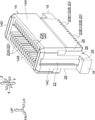
図1~図8に示されるように、本実施形態に係るコネクタ10は、所謂可動(フローティング)コネクタであり、接続対象物としての相手側コネクタ12(図1以外では図示省略)が挿抜される可動ハウジング14と、図示しない回路基板に固定される固定ハウジング30と、を備えている。固定ハウジング30は、可動ハウジング14に対して相手側コネクタ12の挿抜方向(矢印Z方向)と直交する架渡方向(矢印Y方向)の両側に配置された一対の側壁部30A、30Bを有している。
(Constitution)
As shown in FIGS. 1 to 8, the connector 10 according to the present embodiment is a so-called movable (floating) connector, and the mating connector 12 (not shown except for FIG. 1) as a connection target is inserted and removed. It includes a movable housing 14 and a fixed housing 30 fixed to a circuit board (not shown). The fixed housing 30 has a pair of side wall portions 30A and 30B arranged on both sides in a crossing direction (arrow Y direction) orthogonal to the insertion / removal direction (arrow Z direction) of the mating connector 12 with respect to the movable housing 14. ing.

また、このコネクタ10は、可動ハウジング14と一対の側壁部30A、30Bとの間に架渡方向Yに沿って架け渡され、挿抜方向Z及び架渡方向Yと直交する端子配列方向(矢印X方向)に配列された複数の信号端子50と、複数の信号端子50に対して端子配列方向Xの両側に配置され、可動ハウジング14と一対の側壁部30A、30Bとの間に架渡方向Yに沿って架け渡された一対の電源端子70と、を備えている。 Further, the connector 10 is bridged between the movable housing 14 and the pair of side wall portions 30A and 30B along the laying direction Y, and has a terminal arrangement direction (arrow X) orthogonal to the insertion / removal direction Z and the laying direction Y. The plurality of signal terminals 50 arranged in the direction) and the plurality of signal terminals 50 arranged on both sides of the terminal arrangement direction X with respect to the plurality of signal terminals 50. It is provided with a pair of power supply terminals 70, which are bridged along the same line.

このコネクタ10は、基板対基板接続用コネクタのプラグ(雄型)を構成しており、レセプタクル(雌型)である相手側コネクタ12は、上記の回路基板とは別の相手側回路基板に固定される構成になっている。相手側コネクタ12には、複数の信号端子50と電気的に接続される図示しない複数の相手側信号端子と、一対の電源端子70と電気的に接続される図示しない一対の相手側電源端子とが設けられている。 The connector 10 constitutes a plug (male type) of a connector for connecting a board to a board, and the mating side connector 12 which is a receptacle (female type) is fixed to a mating side circuit board different from the above circuit board. It is configured to be. The mating side connector 12 includes a plurality of mating side signal terminals (not shown) electrically connected to the plurality of signal terminals 50, and a pair of mating side power supply terminals (not shown) electrically connected to the pair of power supply terminals 70. Is provided.

なお、コネクタ10の接続対象物は、相手側コネクタ12に限らず、バスバーや角ピンであってもよい。また、本実施形態において、上記の挿抜方向Zは、コネクタ10の上下方向と一致しており、上記の架渡方向Yは、コネクタ10の左右方向と一致しており、上記の端子配列方向Xは、コネクタ10の前後方向と一致している。以下の説明では、挿抜方向Zを「上下方向」と称し、架渡方向Yを「左右方向」と称し、端子配列方向Xを「前後方向」と称する場合がある。このコネクタ10は、前後方向及び左右方向に対称な形状に形成されている。 The object to be connected to the connector 10 is not limited to the mating connector 12, but may be a bus bar or a square pin. Further, in the present embodiment, the above-mentioned insertion / removal direction Z coincides with the vertical direction of the connector 10, the above-mentioned crossing direction Y coincides with the left-right direction of the connector 10, and the above-mentioned terminal arrangement direction X. Is in line with the front-back direction of the connector 10. In the following description, the insertion / removal direction Z may be referred to as "vertical direction", the overhead direction Y may be referred to as "left-right direction", and the terminal arrangement direction X may be referred to as "front-back direction". The connector 10 is formed in a shape symmetrical in the front-rear direction and the left-right direction.

(可動ハウジングについて)
図1~図3、図5~図8に示されるように、可動ハウジング14は、上方へ向けて開口した矩形の有底孔16を有して有底の略矩形筒状(略直方体状)に形成されている。この可動ハウジング14は、左右方向に対向した左右一対の側壁部14A、14Bと、左右の側壁部14A、14Bの前後両端部を左右方向に繋いだ前後一対の連結壁部14C、14Dと、左右の側壁部14A、14Bを左右方向に繋ぐと共に前後の連結壁部14C、14Dを前後方向に繋いだ底壁部14E(図8参照)とを一体に備えている。左右の側壁部14A、14Bは、前後方向に延在しており、前後の連結壁部14C、14Dは、左右方向に延在している。底壁部14Eは、可動ハウジング14の略下半部に設けられており、上下方向に厚く形成されている。この可動ハウジング14は、例えば合成樹脂等の絶縁性材料によって製造されたものである。なお、本実施形態に係る可動ハウジング14は、前後方向を長手とする長尺状に形成されているが、可動ハウジング14における前後方向の寸法は、信号端子50の数によって適宜変更される構成になっている。
(About movable housing)
As shown in FIGS. 1 to 3 and 5 to 8, the movable housing 14 has a rectangular bottomed hole 16 that opens upward and has a bottomed substantially rectangular tube shape (substantially rectangular parallelepiped shape). Is formed in. The movable housing 14 has a pair of left and right side wall portions 14A and 14B facing each other in the left-right direction, and a pair of front and rear connecting wall portions 14C and 14D connecting the front and rear ends of the left and right side wall portions 14A and 14B in the left-right direction. The side wall portions 14A and 14B of the above are connected in the left-right direction, and the bottom wall portion 14E (see FIG. 8) in which the front and rear connecting wall portions 14C and 14D are connected in the front-rear direction is integrally provided. The left and right side wall portions 14A and 14B extend in the front-rear direction, and the front and rear connecting wall portions 14C and 14D extend in the left-right direction. The bottom wall portion 14E is provided in a substantially lower half portion of the movable housing 14, and is formed thick in the vertical direction. The movable housing 14 is manufactured of an insulating material such as synthetic resin. The movable housing 14 according to the present embodiment is formed in a long shape having a longitudinal direction in the front-rear direction, but the dimensions in the front-rear direction of the movable housing 14 are appropriately changed depending on the number of signal terminals 50. It has become.

前後の連結壁部14C、14D(可動ハウジング14の前後両端部)の下端部には、前後方向外側(端子配列方向Xの外側)へ向けて突出した前後一対の係合凸部18が形成されている。前後の係合凸部18は、直方体状に形成されている。 A pair of front-rear engaging protrusions 18 projecting toward the outside in the front-rear direction (outside of the terminal arrangement direction X) are formed at the lower ends of the front-rear connecting wall portions 14C and 14D (both front and rear ends of the movable housing 14). ing. The front and rear engaging protrusions 18 are formed in a rectangular parallelepiped shape.

左右の側壁部14A、14Bにおける有底孔16側の面には、上下方向に延びる複数の信号端子挿入溝20Aが前後方向に等間隔に並んで形成されている。これらの信号端子挿入溝20Aは、有底孔16側及び上方側へ向けて開口している。また、これらの信号端子挿入溝20Aは、底壁部14Eを上下方向に貫通した複数の信号端子挿入孔20Bに連通されている。複数の信号端子挿入孔20Bの下端部は、各側壁部14A、14Bの左右方向両側へ向けて開口した溝状の溝状部20B1とされている。これらの信号端子挿入溝20A及び信号端子挿入孔20Bは、上下方向から見て左右方向を長手とする長尺状に形成されており、信号端子挿入部20を構成している。 On the surface of the left and right side wall portions 14A and 14B on the bottomed hole 16 side, a plurality of signal terminal insertion grooves 20A extending in the vertical direction are formed so as to be arranged at equal intervals in the front-rear direction. These signal terminal insertion grooves 20A are open toward the bottomed hole 16 side and the upper side. Further, these signal terminal insertion grooves 20A are communicated with a plurality of signal terminal insertion holes 20B penetrating the bottom wall portion 14E in the vertical direction. The lower end portion of the plurality of signal terminal insertion holes 20B is a groove-shaped groove-shaped portion 20B1 opened toward both left and right sides of the side wall portions 14A and 14B. These signal terminal insertion grooves 20A and signal terminal insertion holes 20B are formed in a long shape having a longitudinal direction in the left-right direction when viewed from the vertical direction, and constitute a signal terminal insertion portion 20.

前後の連結壁部14C、14Dにおける左右方向中央部には、前後方向外側へ向けて開口した収容凹部22がそれぞれ形成されている。前後の収容凹部22は、上下方向に延びており、係合凸部18の基端部に形成された矩形の貫通孔24に連通されている。この貫通孔24は、係合凸部18の基端部を上下方向に貫通している。また、各収容凹部22の下端部は、可動ハウジング14の下面に形成された左右一対の弾性部挿入溝26に連通されている。左右の弾性部挿入溝26は、左右方向に延びており、左右方向両側へ向けて開口している。また、前後の連結壁部14C、14Dの略下半部における左右方向両側には、それぞればね収容凹部28が形成されている。左右一対のばね収容凹部28は、前後方向外側及び左右方向外側へ向けて開口している。 In the central portion of the front and rear connecting wall portions 14C and 14D in the left-right direction, accommodating recesses 22 opened toward the outside in the front-rear direction are formed, respectively. The front and rear accommodating recesses 22 extend in the vertical direction and communicate with a rectangular through hole 24 formed at the base end portion of the engaging convex portion 18. The through hole 24 penetrates the base end portion of the engaging convex portion 18 in the vertical direction. Further, the lower end portion of each accommodating recess 22 is communicated with a pair of left and right elastic portion insertion grooves 26 formed on the lower surface of the movable housing 14. The left and right elastic portion insertion grooves 26 extend in the left-right direction and open toward both sides in the left-right direction. Further, spring accommodating recesses 28 are formed on both sides in the left-right direction in the substantially lower half of the front and rear connecting wall portions 14C and 14D, respectively. The pair of left and right spring accommodating recesses 28 are open toward the outside in the front-rear direction and the outside in the left-right direction.

(固定ハウジングについて)
図1~図2、図4~図8に示されるように、固定ハウジング30は、上下方向に貫通した矩形の貫通孔32を有して略矩形枠状に形成されている。この固定ハウジング30は、左右方向に対向した左右一対の側壁部30A、30Bと、左右の側壁部30A、30Bの前後方向両端部を左右方向に繋いだ前後一対の連結壁部30C、30Dとを一体に備えている。左右の側壁部30A、30Bは、前後方向に延在しており、前後の連結壁部30C、30Dは、左右方向に延在している。この固定ハウジング30は、例えば合成樹脂等の絶縁性材料によって製造されたものである。なお、本実施形態に係る固定ハウジング30は、前後方向を長手とする長尺状に形成されているが、固定ハウジング30における前後方向の寸法は、信号端子50の数によって適宜変更される構成になっている。
(About fixed housing)
As shown in FIGS. 1 to 2 and 4 to 8, the fixed housing 30 has a rectangular through hole 32 penetrating in the vertical direction and is formed in a substantially rectangular frame shape. The fixed housing 30 includes a pair of left and right side wall portions 30A and 30B facing each other in the left-right direction, and a pair of front-rear connecting wall portions 30C and 30D connecting both ends of the left and right side wall portions 30A and 30B in the front-rear direction in the left-right direction. I am preparing for it all together. The left and right side wall portions 30A and 30B extend in the front-rear direction, and the front and rear connecting wall portions 30C and 30D extend in the left-right direction. The fixed housing 30 is manufactured of an insulating material such as a synthetic resin. The fixed housing 30 according to the present embodiment is formed in a long shape having a longitudinal direction in the front-rear direction, but the dimensions in the front-rear direction of the fixed housing 30 are appropriately changed depending on the number of signal terminals 50. It has become.

固定ハウジング30の貫通孔32の内側には、可動ハウジング14の略下半部が挿入されており、可動ハウジング14の略上半部は、固定ハウジング30の上方側(外側)に配置されている。固定ハウジング30の貫通孔32の内周面と、可動ハウジング14の略下半部の外周面との間には、上下方向から見て略矩形環状の隙間34(図5及び図6以外では符号省略)が形成されている。 A substantially lower half portion of the movable housing 14 is inserted inside the through hole 32 of the fixed housing 30, and a substantially upper half portion of the movable housing 14 is arranged on the upper side (outside) of the fixed housing 30. .. A substantially rectangular annular gap 34 (reference numerals other than those in FIGS. 5 and 6) between the inner peripheral surface of the through hole 32 of the fixed housing 30 and the outer peripheral surface of the substantially lower half of the movable housing 14 when viewed from the vertical direction. Omitted) is formed.

左右の側壁部30A、30Bの前後方向中間部には、上下方向に貫通した複数の信号端子挿入孔36が前後方向に等間隔に並んで形成されている。また、左右の側壁部30A、30Bの前後方向両端部には、上下方向に貫通した電源端子挿入孔38がそれぞれ形成されている。複数の信号端子挿入孔36の下端部は、各側壁部30A、30Bの左右方向両側へ向けて開口した溝状の溝状部36Aとされている。前後の電源端子挿入孔38は、上下方向から見て前後方向を長手とする長尺状に形成されている。 A plurality of signal terminal insertion holes 36 penetrating in the vertical direction are formed in the middle portions in the front-rear direction of the left and right side wall portions 30A and 30B so as to be arranged at equal intervals in the front-rear direction. Further, power supply terminal insertion holes 38 penetrating in the vertical direction are formed at both ends of the left and right side wall portions 30A and 30B in the front-rear direction. The lower end portions of the plurality of signal terminal insertion holes 36 are groove-shaped groove-shaped portions 36A that are opened toward both left and right sides of the side wall portions 30A and 30B. The front and rear power supply terminal insertion holes 38 are formed in a long shape having a longitudinal direction in the front-rear direction when viewed from the vertical direction.

前後の連結壁部30C、30Dの左右方向中間部の下部には、上方側へ凹んだ係合凹部40がそれぞれ形成されている。前後の係合凹部40内には、可動ハウジング14に形成された前後の係合凸部18が配置されている。各係合凸部18の上面は、各係合凹部40の上面に対して接触又は近接して対向している。これらの係合凸部18及び係合凹部40は、可動ハウジング14が固定ハウジング30に対して上方側へ脱落することを防止する抜止として機能する。また、各係合凸部18の左右両側面と、各係合凹部40の左右両側面との間には、固定ハウジング30に対する可動ハウジング14の相対移動を許容するための隙間がそれぞれ形成されている。 Engagement recesses 40 recessed upward are formed in the lower portions of the front and rear connecting wall portions 30C and 30D in the middle portion in the left-right direction. In the front and rear engaging recesses 40, front and rear engaging protrusions 18 formed on the movable housing 14 are arranged. The upper surface of each engaging protrusion 18 is in contact with or in close contact with the upper surface of each engaging recess 40. These engaging protrusions 18 and engaging recesses 40 function as retaining parts to prevent the movable housing 14 from falling off upward with respect to the fixed housing 30. Further, a gap is formed between the left and right side surfaces of each engaging protrusion 18 and the left and right side surfaces of each engaging recess 40 to allow the movable housing 14 to move relative to the fixed housing 30. There is.

また、前後の連結壁部30C、30Dの下面には、下方側へ突出した位置決めボス42がそれぞれ形成されている。前側の位置決めボス42は、前側の係合凹部40に対して左側に配置されており、後側の位置決めボス42は、後側の係合凹部40に対して右側に配置されている。これらの位置決めボス42は、回路基板に形成された位置決め孔に嵌入される構成になっている。 Further, positioning bosses 42 protruding downward are formed on the lower surfaces of the front and rear connecting wall portions 30C and 30D, respectively. The front positioning boss 42 is arranged on the left side with respect to the front engaging recess 40, and the rear positioning boss 42 is arranged on the right side with respect to the rear engaging recess 40. These positioning bosses 42 are configured to be fitted into positioning holes formed in the circuit board.

(信号端子について)
図1~図2、図5~図9に示されるように、複数の信号端子50は、導電性を有する金属板が所定の形状に打ち抜ぬかれて製造されたものであり、左右一対の端子列52A、52Bを構成している。左右の端子列52A、52Bは、それぞれ複数の信号端子50が前後方向に等間隔に並べられた構成になっている。左側の端子列52Aが有する複数の信号端子50と、右側の端子列52Bが有する複数の信号端子50とは、同一の形状に形成されているが、互いに左右方向に反対向きの姿勢で配置されている。左側の端子列52Aが有する複数の信号端子50は、固定ハウジング30の左側の側壁部30Aと、可動ハウジング14との間に左右方向に沿って架け渡されており、右側の端子列52Bが有する複数の信号端子50は、固定ハウジング30の右側の側壁部30Bと、可動ハウジング14との間に左右方向に沿って架け渡されている。なお、図9には、左側の端子列52Aが有する一の信号端子50と、右側の端子列52Bが有する一の信号端子50とが図示されている。
(About signal terminal)
As shown in FIGS. 1 to 2 and 5 to 9, the plurality of signal terminals 50 are manufactured by punching a conductive metal plate into a predetermined shape, and a pair of left and right signal terminals. The terminal rows 52A and 52B are configured. The left and right terminal rows 52A and 52B each have a configuration in which a plurality of signal terminals 50 are arranged at equal intervals in the front-rear direction. The plurality of signal terminals 50 possessed by the terminal row 52A on the left side and the plurality of signal terminals 50 possessed by the terminal row 52B on the right side are formed in the same shape, but are arranged in opposite positions in the left-right direction. ing. The plurality of signal terminals 50 included in the left terminal row 52A are bridged along the left-right direction between the left side wall portion 30A of the fixed housing 30 and the movable housing 14, and the right terminal row 52B has. The plurality of signal terminals 50 are bridged along the left-right direction between the side wall portion 30B on the right side of the fixed housing 30 and the movable housing 14. Note that FIG. 9 shows one signal terminal 50 included in the left terminal row 52A and one signal terminal 50 included in the right terminal row 52B.

各信号端子50は、可動ハウジング14に保持され、相手側コネクタ12に設けられた相手側信号端子と電気的に接触されて左右方向外側へ弾性変形する第一接触部50Aと、第一接触部50Aから左右方向外側へ延出され、弾性変形可能とされた第一弾性部50Bと、第一弾性部50Bにおける第一接触部50Aとは反対側の端部から左右方向外側へ延出されて固定ハウジング30に保持され、回路基板に固定される第一接続部50Cと、を有している。 Each signal terminal 50 is held in a movable housing 14, and is electrically contacted with the mating side signal terminal provided on the mating side connector 12 to elastically deform outward in the left-right direction, and a first contact portion 50A and a first contact portion. The first elastic portion 50B extending outward in the left-right direction from 50A and elastically deformable, and the first elastic portion 50B extending outward in the left-right direction from the end opposite to the first contact portion 50A. It has a first connection portion 50C, which is held in the fixed housing 30 and fixed to the circuit board.

第一接触部50Aは、前後方向を板厚方向とし且つ上下方向を長手方向とする長尺板状に形成されており、可動ハウジング14の信号端子挿入部20に対して下方側から挿入されている。この第一接触部50Aの略下半部は、可動ハウジング14の信号端子挿入孔20B内に挿入(圧入)された第一保持部50A1とされている。この第一保持部50A1には、可動ハウジング14の左右方向中央側へ突出した複数の爪部54が上下方向に並んで形成されている。これら複数の爪部54が信号端子挿入孔20Bの内周面に食い込むことで、第一保持部50A1が可動ハウジング14に保持されている。 The first contact portion 50A is formed in a long plate shape having a plate thickness direction in the front-rear direction and a longitudinal direction in the vertical direction, and is inserted from below with respect to the signal terminal insertion portion 20 of the movable housing 14. There is. The substantially lower half of the first contact portion 50A is a first holding portion 50A1 inserted (press-fitted) into the signal terminal insertion hole 20B of the movable housing 14. The first holding portion 50A1 is formed with a plurality of claw portions 54 projecting toward the center side in the left-right direction of the movable housing 14 side by side in the vertical direction. The first holding portion 50A1 is held by the movable housing 14 by the plurality of claw portions 54 biting into the inner peripheral surface of the signal terminal insertion hole 20B.

第一接触部50Aの略上半部は、上下方向に延びるスリット55によって左右方向に分割された左右一対の第一接点弾性部50A2、50A3とされている。これらの第一接点弾性部50A2、50A3は、可動ハウジング14の信号端子挿入溝20A内に挿入されており、左右方向に弾性変形可能とされている。左右方向外側の第一接点弾性部50A2は、左右方向中央側の第一接点弾性部50A3よりも上方側へ延びている。左右の第一接点弾性部50A2、50A3の上端部には、それぞれ可動ハウジング14の有底孔16内へ突出した第一接点部56、58が形成されている。これらの第一接点部56、58は、相手側コネクタ12に設けられた相手側信号端子と接触される。これにより、信号端子50が相手側信号端子と電気的に接続される。この電気的な接続は、第一接点部56、58のうちの一方が損傷した場合でも、第一接点部56、58のうちの他方によって確保される構成になっている。 The substantially upper half of the first contact portion 50A is a pair of left and right first contact elastic portions 50A2 and 50A3 divided in the left-right direction by a slit 55 extending in the vertical direction. These first contact elastic portions 50A2 and 50A3 are inserted into the signal terminal insertion groove 20A of the movable housing 14, and are elastically deformable in the left-right direction. The first contact elastic portion 50A2 on the outer side in the left-right direction extends upward from the first contact elastic portion 50A3 on the central side in the left-right direction. At the upper ends of the left and right first contact elastic portions 50A2 and 50A3, first contact portions 56 and 58 projecting into the bottomed hole 16 of the movable housing 14, respectively, are formed. These first contact portions 56 and 58 are in contact with the mating side signal terminal provided on the mating side connector 12. As a result, the signal terminal 50 is electrically connected to the other party's signal terminal. This electrical connection is configured to be secured by the other of the first contacts 56, 58 even if one of the first contacts 56, 58 is damaged.

第一接続部50Cは、固定ハウジング30の信号端子挿入孔36に対して下方側から挿入(圧入)された第一圧入部50C1と、第一圧入部50C1の下端から左右方向外側へ延出され、信号端子挿入孔36の溝状部36A内に挿入された第一接続片50C2とを有しており、前後方向視で略L字状に形成されている。第一圧入部50C1の上部には、固定ハウジング30の左右方向中央側へ突出した爪部60が形成されている。この爪部60が信号端子挿入孔36の内周面に引っ掛かることで、第一圧入部50C1が固定ハウジング30に保持されている。第一接続片50C2は、固定ハウジング30よりも左右方向外側へ突出している。この第一接続片50C2は、ハンダ付け等の手段によって回路基板に固定(電気的に接続)される構成になっている。 The first connection portion 50C extends outward in the left-right direction from the lower end of the first press-fitting portion 50C1 inserted (press-fitted) into the signal terminal insertion hole 36 of the fixed housing 30 from below and the first press-fitting portion 50C1. It has a first connection piece 50C2 inserted into the groove-shaped portion 36A of the signal terminal insertion hole 36, and is formed in a substantially L-shape in the front-rear direction. A claw portion 60 protruding toward the center in the left-right direction of the fixed housing 30 is formed on the upper portion of the first press-fitting portion 50C1. The first press-fitting portion 50C1 is held by the fixed housing 30 by hooking the claw portion 60 on the inner peripheral surface of the signal terminal insertion hole 36. The first connection piece 50C2 projects outward in the left-right direction from the fixed housing 30. The first connection piece 50C2 is configured to be fixed (electrically connected) to the circuit board by means such as soldering.

第一弾性部50Bは、信号端子50の左右方向中間部を構成しており、第一接触部50Aの下端から左右方向外側へ一体に延出されている。この第一弾性部50Bにおける第一接触部50Aとは反対側の端部からは、上記の第一接続部50Cが一体に延出されている。この第一弾性部50Bは、左右方向中間部が上方(相手側コネクタ12の抜去方向)へ凸をなして曲がった第一ばね部50B1とされている。この第一ばね部50B1は、前後方向から見て下方側が開放された逆U字状をなしている。 The first elastic portion 50B constitutes an intermediate portion in the left-right direction of the signal terminal 50, and extends integrally from the lower end of the first contact portion 50A to the outside in the left-right direction. The first connecting portion 50C is integrally extended from the end portion of the first elastic portion 50B opposite to the first contact portion 50A. The first elastic portion 50B is a first spring portion 50B1 in which an intermediate portion in the left-right direction is bent upward (in the direction in which the mating connector 12 is removed). The first spring portion 50B1 has an inverted U shape with the lower side open when viewed from the front-rear direction.

(電源端子について)
図1~図2、図5~図8、図10~図13に示されるように、一対の電源端子70は、導電性を有する金属板が打ち抜かれると共に、折り曲げ加工を施されて製造されたものである。一対の電源端子70は、複数の信号端子50に対して前後方向両側に配置されている。これら一対の電源端子70は、同一の形状に形成されており、互いに前後方向に反対向きの姿勢で配置されている。各電源端子70は、上下方向から見て左右方向を長手とする長尺状に形成されており、一対の側壁部30A、30B間に架け渡されている。各電源端子70の左右方向中間部は、可動ハウジング14における前後方向の端部に保持されている。また、各電源端子70は、可動ハウジング14と一対の側壁部30A、30Bとの間に位置する部位に、それぞれ弾性変形可能な第二弾性部70Bを有している。なお、本実施形態では、各電源端子70における上下方向の寸法が、各電源端子70における左右方向の寸法よりも若干短く設定されているが、これに限るものではない。各電源端子70における上下方向の寸法は、コネクタ10の仕様等に応じて適宜変更可能であり、各電源端子70が、前後方向(端子配列方向X)から見て上下方向(挿抜方向Z)を長手とする長尺状に形成された構成にしてもよい。
(About power supply terminal)
As shown in FIGS. 1 to 2, FIGS. 5 to 8, and FIGS. 10 to 13, the pair of power supply terminals 70 are manufactured by punching out a conductive metal plate and bending the metal plate. It is a thing. The pair of power supply terminals 70 are arranged on both sides in the front-rear direction with respect to the plurality of signal terminals 50. These pair of power supply terminals 70 are formed in the same shape and are arranged in opposite postures in the front-rear direction. Each power supply terminal 70 is formed in a long shape having a longitudinal direction in the left-right direction when viewed from the vertical direction, and is bridged between a pair of side wall portions 30A and 30B. The left-right intermediate portion of each power supply terminal 70 is held at the front-rear end portion of the movable housing 14. Further, each power supply terminal 70 has a second elastic portion 70B elastically deformable at a portion located between the movable housing 14 and the pair of side wall portions 30A and 30B. In the present embodiment, the vertical dimension of each power supply terminal 70 is set to be slightly shorter than the horizontal dimension of each power supply terminal 70, but the present invention is not limited to this. The vertical dimensions of each power supply terminal 70 can be appropriately changed according to the specifications of the connector 10, and each power supply terminal 70 has a vertical direction (insertion / extraction direction Z) when viewed from the front-rear direction (terminal arrangement direction X). It may be configured to be long and long.

各電源端子70の左右方向中間部(左右方向中央部)には、第二接触部70Aが設けられている。第二接触部70Aは、相手側コネクタ12に設けられた相手側電源端子と電気的に接触されて複数の信号端子50側へ弾性変形する。また、各電源端子70は、第二接触部70Aから左右方向両側へそれぞれ延出された前記一対の第二弾性部70Bと、左右の第二弾性部70Bにおける第二接触部70Aとは反対側の端部からそれぞれ前後方向外側へ延出された左右一対の第二接続部70Cとを有している。左右の第二接続部70Cは、固定ハウジング30に保持されると共に、回路基板に固定される構成になっている。第二接触部70Aは、本発明における「接触部」に相当し、第二接続部70Cは、本発明における「接続部」に相当する。以下、具体的に説明する。 A second contact portion 70A is provided at an intermediate portion in the left-right direction (central portion in the left-right direction) of each power supply terminal 70. The second contact portion 70A is electrically contacted with the mating side power supply terminal provided on the mating side connector 12 and elastically deforms toward the plurality of signal terminals 50. Further, each power supply terminal 70 is on the opposite side of the pair of second elastic portions 70B extending from the second contact portion 70A to both sides in the left-right direction and the second contact portions 70A in the left and right second elastic portions 70B. It has a pair of left and right second connecting portions 70C extending outward in the front-rear direction from the end portions of the above. The left and right second connection portions 70C are held in the fixed housing 30 and are fixed to the circuit board. The second contact portion 70A corresponds to the "contact portion" in the present invention, and the second connection portion 70C corresponds to the "connection portion" in the present invention. Hereinafter, a specific description will be given.

第二接触部70Aは、前後方向を板厚方向とし且つ上下方向を長手方向とする長尺板状に形成されている。この第二接触部70Aは、前後方向に沿った板厚寸法が、左右方向に沿った幅寸法よりも小さく設定されている。この第二接触部70Aの一部(後述する左右の第二接点部71A1、71B1を除く大部分)は、可動ハウジング14の収容凹部22内に収容されている。この第二接触部70Aの下部は、第二保持部70A1とされている。第二保持部70A1は、可動ハウジング14の収容凹部22内の下部に挿入(圧入)されている。この第二保持部70A1には、左右方向両側へ突出した複数の爪部72が上下方向に並んで形成されている。これら複数の爪部72が収容凹部22の左右の側面に食い込むことで、第二保持部70A1が可動ハウジング14に保持されている。 The second contact portion 70A is formed in the shape of a long plate having the front-rear direction as the plate thickness direction and the vertical direction as the longitudinal direction. The plate thickness dimension along the front-rear direction of the second contact portion 70A is set to be smaller than the width dimension along the left-right direction. A part of the second contact portion 70A (most of the left and right second contact portions 71A1 and 71B1 to be described later) is housed in the housing recess 22 of the movable housing 14. The lower part of the second contact portion 70A is a second holding portion 70A1. The second holding portion 70A1 is inserted (press-fitted) into the lower part of the accommodating recess 22 of the movable housing 14. The second holding portion 70A1 is formed with a plurality of claw portions 72 projecting from both sides in the left-right direction side by side in the vertical direction. The second holding portion 70A1 is held by the movable housing 14 by the plurality of claw portions 72 biting into the left and right side surfaces of the accommodating recess 22.

第二接触部70Aの上下方向中間部及び上部は、前後方向に弾性変形可能な第二接点弾性部70A2とされている。この第二接点弾性部70A2は、収容凹部22内の上下方向中間部から上部にわたって延在している。この第二接点弾性部70A2は、上方側へ向かうほど左右方向の幅が僅かに減少するように形成されており、収容凹部22の左右の側面に対して非接触状態で配置されている。また、この第二接点弾性部70A2と第二保持部70A1との間には、屈曲部74が形成されており、第二接点弾性部70A2は、上方側へ向かうほど前後方向外側へ向かうように上下方向に対して僅かに傾斜している。これにより、第二接点弾性部70A2と収容凹部22の底面との間には、第二接点弾性部70A2が複数の信号端子50側(可動ハウジング14の前後方向中央側)へ弾性変形するための隙間22A(図8参照)が形成されている。 The vertical intermediate portion and the upper portion of the second contact portion 70A are the second contact elastic portions 70A2 that can be elastically deformed in the front-rear direction. The second contact elastic portion 70A2 extends from the vertical intermediate portion in the accommodating recess 22 to the upper portion. The second contact elastic portion 70A2 is formed so that the width in the left-right direction slightly decreases toward the upper side, and is arranged in a non-contact state with respect to the left and right side surfaces of the accommodating recess 22. Further, a bent portion 74 is formed between the second contact elastic portion 70A2 and the second holding portion 70A1, and the second contact elastic portion 70A2 is directed outward in the front-rear direction as it goes upward. It is slightly tilted with respect to the vertical direction. As a result, between the second contact elastic portion 70A2 and the bottom surface of the accommodating recess 22, the second contact elastic portion 70A2 is elastically deformed toward the plurality of signal terminals 50 (center side in the front-rear direction of the movable housing 14). A gap 22A (see FIG. 8) is formed.

この第二接点弾性部70A2の上部は、上下方向に延びるスリット76によって左右一対の分割部71A、71Bに分割されている。また、左右の分割部71A、71Bの上部には、前後方向外側へ向けて略円弧状に膨出した第二接点部71A1、71B1が設けられている。これらの第二接点部71A1、71B1は、収容凹部22の前後方向外側へ突出しており、相手側コネクタ12に設けられた相手側電源端子と接触される。これにより、電源端子70が相手側電源端子と電気的に接続される。この電気的な接続は、第二接点部71A1、71B1のうちの一方が損傷した場合でも、第二接点部71A1、71B1のうちの他方によって確保される構成になっている。なお、第二接点弾性部70A2の上部がスリット76によって左右の分割部71A、71B(左右の第二接点部71A1、71B1)に分割された構成に限らず、スリット76が省略された構成にしてもよい。 The upper portion of the second contact elastic portion 70A2 is divided into a pair of left and right split portions 71A and 71B by a slit 76 extending in the vertical direction. Further, at the upper part of the left and right divided portions 71A and 71B, second contact portions 71A1 and 71B1 bulging in a substantially arc shape toward the outside in the front-rear direction are provided. These second contact portions 71A1 and 71B1 project outward in the front-rear direction of the accommodating recess 22, and are in contact with the mating side power supply terminal provided on the mating side connector 12. As a result, the power supply terminal 70 is electrically connected to the other side power supply terminal. This electrical connection is configured to be secured by the other of the second contact portions 71A1 and 71B1 even if one of the second contact portions 71A1 and 71B1 is damaged. The upper portion of the second contact elastic portion 70A2 is not limited to the configuration in which the upper portion is divided into the left and right divided portions 71A and 71B (left and right second contact portions 71A1 and 71B1) by the slit 76, and the slit 76 is omitted. May be good.

左右の第二接続部70Cは、固定ハウジング30の電源端子挿入孔38に対して下方側から挿入(圧入)された第二圧入部70C1と、第二圧入部70C1の下端から左右方向外側へ延出された第二接続片70C2とを有しており、前後方向視で略L字状に形成されている。第二圧入部70C1の上部には、前後方向両側へ突出した複数の爪部78が上下方向に並んで形成されている。これらの爪部78が電源端子挿入孔38の内周面に食い込むことで、第二圧入部70C1が固定ハウジング30に保持されている。左右の第二接続片70C2は、固定ハウジング30よりも左右方向外側へ突出している。これらの第二接続部70C、ハンダ付け等の手段によって回路基板に固定(電気的に接続)される構成になっている。 The left and right second connection portions 70C extend from the lower ends of the second press-fitting portion 70C1 inserted (press-fitted) into the power supply terminal insertion hole 38 of the fixed housing 30 from below and outward in the left-right direction. It has a second connecting piece 70C2 that has been taken out, and is formed in a substantially L shape in the front-back direction. On the upper portion of the second press-fitting portion 70C1, a plurality of claw portions 78 projecting from both sides in the front-rear direction are formed side by side in the vertical direction. The second press-fitting portion 70C1 is held in the fixed housing 30 by the claw portions 78 biting into the inner peripheral surface of the power supply terminal insertion hole 38. The left and right second connection pieces 70C2 project outward from the fixed housing 30 in the left-right direction. The second connection portion 70C is fixed (electrically connected) to the circuit board by means such as soldering.

左右の第二弾性部70Bは、第二接触部70Aの第二保持部70A1の下端から左右方向両側へ一体に延出されている。これらの第二弾性部70Bにおける第二接触部70Aとは反対側の端部からは、左右の第二接続部70Cが一体に延出されている。左右の第二弾性部70Bにおける第二接触部70A側の端部は、可動ハウジング14の下面に形成された左右の弾性部挿入溝26内に挿入されている。また、左右の第二弾性部70Bの左右方向中間部は、上方(相手側コネクタ12の抜去方向)へ凸をなして曲がった第二ばね部70B1とされている。これらの第二ばね部70B1は、前後方向から見て下方側が開放された逆U字状をなしている。左右の第二弾性部70Bの一部(第二接触部70A側の略半分の部位)は、可動ハウジング14の左右のばね収容凹部28に収容されている。 The left and right second elastic portions 70B are integrally extended from the lower end of the second holding portion 70A1 of the second contact portion 70A to both sides in the left-right direction. The left and right second connecting portions 70C extend integrally from the end portions of these second elastic portions 70B opposite to the second contact portion 70A. The ends of the left and right second elastic portions 70B on the second contact portion 70A side are inserted into the left and right elastic portion insertion grooves 26 formed on the lower surface of the movable housing 14. Further, the left-right intermediate portion of the left and right second elastic portions 70B is a second spring portion 70B1 that is bent upward (in the direction of removal of the mating connector 12). These second spring portions 70B1 have an inverted U shape with the lower side open when viewed from the front-rear direction. A part of the left and right second elastic portions 70B (substantially half of the portion on the second contact portion 70A side) is accommodated in the left and right spring accommodating recesses 28 of the movable housing 14.

(作用及び効果)
次に、本実施形態の作用及び効果について説明する。
(Action and effect)
Next, the operation and effect of this embodiment will be described.

上記構成のコネクタ10では、固定ハウジング30の一対の側壁部30A、30Bと可動ハウジング14との間に、複数の信号端子50及び一対の電源端子70が架け渡されている。複数の信号端子50は、上下方向(挿抜方向Z)及び左右方向(架渡方向Y)と直交する前後方向(端子配列方向X)に配列されており、架渡方向Yの中間部に弾性変形可能な第一弾性部50Bを有している。一対の電源端子70は、複数の信号端子50に対して端子配列方向Xの両側に配置され、一対の側壁部30A、30B間に架け渡されている。これらの電源端子70は、架渡方向Yの中間部が可動ハウジング14における端子配列方向Xの端部に保持されており、一対の側壁部30A、30Bと可動ハウジング14との間に位置する部位にそれぞれ弾性変形可能な第二弾性部70Bを有している。 In the connector 10 having the above configuration, a plurality of signal terminals 50 and a pair of power supply terminals 70 are bridged between the pair of side wall portions 30A and 30B of the fixed housing 30 and the movable housing 14. The plurality of signal terminals 50 are arranged in the front-rear direction (terminal arrangement direction X) orthogonal to the vertical direction (insertion / extraction direction Z) and the left-right direction (bridge direction Y), and are elastically deformed in the middle portion of the bridge direction Y. It has a possible first elastic portion 50B. The pair of power supply terminals 70 are arranged on both sides of the terminal arrangement direction X with respect to the plurality of signal terminals 50, and are bridged between the pair of side wall portions 30A and 30B. In these power supply terminals 70, the intermediate portion in the crossing direction Y is held at the end portion of the movable housing 14 in the terminal arrangement direction X, and is a portion located between the pair of side wall portions 30A and 30B and the movable housing 14. Each has a second elastic portion 70B that can be elastically deformed.

このコネクタ10では、各信号端子50が有する第一弾性部50Bと、各電源端子70が有する一対の第二弾性部70Bとが弾性変形することで、固定ハウジング30に対する可動ハウジング14の相対移動が許容される。これにより、コネクタ10と相手側コネクタ12との嵌合ずれを吸収することができる。 In this connector 10, the first elastic portion 50B of each signal terminal 50 and the pair of second elastic portions 70B of each power supply terminal 70 are elastically deformed, so that the movable housing 14 moves relative to the fixed housing 30. Permissible. As a result, it is possible to absorb the misalignment between the connector 10 and the mating connector 12.

しかも、このコネクタ10は、信号端子50と電源端子70とを併せ持っているので、信号端子を持つコネクタと電源端子を持つコネクタとを別々に回路基板に取り付ける場合と比較して、回路基板上でのコネクタ10の設置スペースを省スペース化することができると共に、回路基板へのコネクタ10の組付作業を簡素化することができる。 Moreover, since the connector 10 has both the signal terminal 50 and the power supply terminal 70, the connector having the signal terminal and the connector having the power supply terminal are separately mounted on the circuit board as compared with the case where the connector has the signal terminal and the power supply terminal. The installation space of the connector 10 can be saved, and the work of assembling the connector 10 to the circuit board can be simplified.

さらに、このコネクタ10では、複数の信号端子50と一対の電源端子70とが、共通の可動ハウジング14と固定ハウジング30との間に架け渡されているので、複数の可動ハウジングが端子配列方向Xに並んで設けられた構成と比較して、端子配列方向Xにおける可動ハウジング14の配置スペースを小さくすることができる。しかも、各電源端子70が、挿抜方向Zから見て架渡方向Yを長手とする長尺状に形成されているので、端子配列方向Xにおける各電源端子70の配置スペースを小さくすることができる。以上のことから、本実施形態に係るコネクタ10では、全体構成を端子配列方向Xに小型化することができる。 Further, in this connector 10, since the plurality of signal terminals 50 and the pair of power supply terminals 70 are bridged between the common movable housing 14 and the fixed housing 30, the plurality of movable housings are arranged in the terminal arrangement direction X. The arrangement space of the movable housing 14 in the terminal arrangement direction X can be reduced as compared with the configuration provided side by side. Moreover, since each power supply terminal 70 is formed in a long shape having a longitudinal direction Y when viewed from the insertion / removal direction Z, the arrangement space of each power supply terminal 70 in the terminal arrangement direction X can be reduced. .. From the above, in the connector 10 according to the present embodiment, the overall configuration can be miniaturized in the terminal arrangement direction X.

また、このコネクタ10では、電源端子70の架渡方向の中間部に設けられた第二接触部70Aが、可動ハウジング14における端子配列方向Xの端部に保持されている。この第二接触部70Aは、相手側コネクタ12に設けられた相手側電源端子と電気的に接触されて複数の信号端子50側へ弾性変形するので、第二接触部70Aが弾性変形するためのスペースを複数の信号端子50とは反対側(端子配列方向Xの外側)に確保する必要が無い。また、電源端子70が有する一対の第二弾性部70Bは、第二接触部70Aから架渡方向Yの両側へそれぞれ延出されているので、端子配列方向Xにおける一対の第二弾性部70Bの配置スペースを小さく設定することができる。さらに、電源端子70が有する一対の第二接続部70Cは、一対の第二弾性部70Bにおける第二接触部70Aとは反対側の端部からそれぞれ端子配列方向Xの外側(複数の信号端子50とは反対側)へ延出されている。このように一対の第二接続部70Cの延出方向が設定されているので、一対の第二接続部70Cが、一対の第二弾性部70Bにおける第二接触部70Aとは反対側の端部からそれぞれ複数の信号端子50側へ延出されている構成と比較して、第二接触部70A及び一対の第二弾性部70Bを複数の信号端子50に近づけて配置させることができる。その結果、第二接触部70Aが端子配列方向Xの端部に保持される可動ハウジング14を、端子配列方向Xに小型化することができる。以上のことから、本実施形態によれば、コネクタ10の全体構成を端子配列方向Xに更に小型化することができる。 Further, in the connector 10, the second contact portion 70A provided in the intermediate portion of the power supply terminal 70 in the extending direction is held at the end portion of the movable housing 14 in the terminal arrangement direction X. Since the second contact portion 70A is electrically contacted with the mating side power supply terminal provided on the mating side connector 12 and elastically deforms toward the plurality of signal terminals 50, the second contact portion 70A elastically deforms. It is not necessary to secure a space on the side opposite to the plurality of signal terminals 50 (outside the terminal arrangement direction X). Further, since the pair of second elastic portions 70B of the power supply terminal 70 extend from the second contact portion 70A to both sides in the overhead direction Y, the pair of second elastic portions 70B in the terminal arrangement direction X respectively. The placement space can be set small. Further, the pair of second connection portions 70C included in the power supply terminals 70 are located outside the terminal arrangement direction X (plural signal terminals 50) from the ends of the pair of second elastic portions 70B opposite to the second contact portion 70A. Is extended to the opposite side). Since the extending direction of the pair of second connecting portions 70C is set in this way, the pair of second connecting portions 70C is the end portion of the pair of second elastic portions 70B opposite to the second contact portion 70A. The second contact portion 70A and the pair of second elastic portions 70B can be arranged closer to the plurality of signal terminals 50 as compared with the configuration extending from each of the plurality of signal terminals 50 to the side. As a result, the movable housing 14 in which the second contact portion 70A is held at the end of the terminal arrangement direction X can be miniaturized in the terminal arrangement direction X. From the above, according to the present embodiment, the overall configuration of the connector 10 can be further miniaturized in the terminal arrangement direction X.

また、このコネクタ10では、電源端子70が有する一対の第二弾性部70Bが、第二接触部70Aから架渡方向Yの両側へそれぞれ延出されている(架渡方向Yの両側へ分岐している)。これにより、例えば、電源端子70の一対の第二弾性部70Bが第二接触部70Aに対する架渡方向Yの一方側で端子配列方向Xに分岐されている構成と比較して、各第二弾性部70Bが弾性変形し易くなる。 Further, in this connector 10, the pair of second elastic portions 70B of the power supply terminal 70 extend from the second contact portion 70A to both sides in the carrying direction Y (branch to both sides in the carrying direction Y). ing). Thereby, for example, as compared with the configuration in which the pair of second elastic portions 70B of the power supply terminal 70 are branched in the terminal arrangement direction X on one side of the carrying direction Y with respect to the second contact portion 70A, each second elastic portion 70 The portion 70B is easily elastically deformed.

また、このコネクタ10では、可動ハウジング14における端子配列方向Xの端部には、端子配列方向Xの外側へ向けて開口した収容凹部22が形成されている。この収容凹部22には、電源端子70が有する第二接触部70Aの大部分が収容されている。これにより、本コネクタ10の全体構成を端子配列方向Xに小型化するに際し、第二接触部70Aの配置スペースを確保し易くなる。 Further, in the connector 10, a housing recess 22 opened toward the outside of the terminal arrangement direction X is formed at the end of the movable housing 14 in the terminal arrangement direction X. Most of the second contact portion 70A of the power supply terminal 70 is accommodated in the accommodating recess 22. This makes it easier to secure an arrangement space for the second contact portion 70A when the entire configuration of the connector 10 is miniaturized in the terminal arrangement direction X.

しかも、このコネクタ10では、可動ハウジング14における端子配列方向Xの端部には、端子配列方向Xの外側及び架渡方向Yの外側へ向けて開口した一対のばね収容凹部28が形成されている。これら一対のばね収容凹部28には、電源端子70が有する一対の第二弾性部70Bの一部が収容されている。これにより、本コネクタ10の全体構成を端子配列方向Xに小型化するに際し、一対の第二弾性部70Bの配置スペースを確保し易くなる。 Moreover, in this connector 10, a pair of spring accommodating recesses 28 opened toward the outside of the terminal arrangement direction X and the outside of the extension direction Y are formed at the end of the movable housing 14 in the terminal arrangement direction X. .. A part of the pair of second elastic portions 70B included in the power supply terminal 70 is accommodated in the pair of spring accommodating recesses 28. As a result, when the entire configuration of the connector 10 is miniaturized in the terminal arrangement direction X, it becomes easy to secure a space for arranging the pair of second elastic portions 70B.

換言すれば、可動ハウジング14の配置スペースとなるデッドスペースに収容凹部22及び一対のばね収容凹部28が形成され、これらの凹部22、28内に第二接触部70A及び一対の第二弾性部70Bの一部が収容されているので、コネクタ10の全体構成を端子配列方向Xに更に小型化し易くなる。 In other words, the accommodating recess 22 and the pair of spring accommodating recesses 28 are formed in the dead space that is the arrangement space of the movable housing 14, and the second contact portion 70A and the pair of second elastic portions 70B are formed in these recesses 22 and 28. Since a part of the connector 10 is accommodated, the entire configuration of the connector 10 can be further miniaturized in the terminal arrangement direction X.

また、このコネクタ10では、電源端子70が有する第二接触部70Aは、端子配列方向Xに沿った板厚寸法が架渡方向Yに沿った幅寸法より小さい板状に形成されている。この第二接触部70Aを有する電源端子70には、信号端子50よりも大きな電流が流れるため、断面積を大きく確保することが求められる。この点、本実施形態によれば、第二接触部70Aの断面積を上記の幅寸法によって確保しつつ、端子配列方向Xにおける第二接触部70Aの寸法を小さく設定することができる。したがって、本実施形態によれば、コネクタ10の全体構成を端子配列方向Xに更に小型化し易くなる。 Further, in the connector 10, the second contact portion 70A of the power supply terminal 70 is formed in a plate shape in which the plate thickness dimension along the terminal arrangement direction X is smaller than the width dimension along the spanning direction Y. Since a current larger than that of the signal terminal 50 flows through the power supply terminal 70 having the second contact portion 70A, it is required to secure a large cross-sectional area. In this respect, according to the present embodiment, the dimension of the second contact portion 70A in the terminal arrangement direction X can be set small while ensuring the cross-sectional area of the second contact portion 70A by the above width dimension. Therefore, according to the present embodiment, the overall configuration of the connector 10 can be further miniaturized in the terminal arrangement direction X.

さらに、このコネクタ10では、電源端子70が有する一対の第二弾性部70Bは、可動ハウジング14の抜去方向(上方)へ凸をなして曲がった第二ばね部70B1を有している。これにより、端子配列方向Xにおける一対の第二弾性部70Bの寸法を小さく設定しつつ、一対の第二弾性部70Bを弾性変形させ易くなる。 Further, in the connector 10, the pair of second elastic portions 70B of the power supply terminal 70 has a second spring portion 70B1 that is bent so as to be convex in the removal direction (upward) of the movable housing 14. As a result, the pair of second elastic portions 70B can be easily elastically deformed while the size of the pair of second elastic portions 70B in the terminal arrangement direction X is set small.

<実施形態の補足説明>
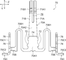
上記実施形態では、電源端子70が有する第二接触部70Aの上端部に、左右方向(架渡方向Y)に並んだ一対の第二接点部71A1、71B1が設けられた構成にしたが、これに限るものではない。例えば図14に示される電源端子70’(変形例)のように、第二接触部70A’の上端部に、上下方向(挿抜方向Z)に並んだ一対の第二接点部71C1、71D1が設けられた構成にしてもよい。
<Supplementary explanation of the embodiment>
In the above embodiment, a pair of second contact portions 71A1 and 71B1 arranged in the left-right direction (crossing direction Y) are provided at the upper end portion of the second contact portion 70A of the power supply terminal 70. It is not limited to. For example, as in the power supply terminal 70'(deformed example) shown in FIG. 14, a pair of second contact portions 71C1 and 71D1 arranged in the vertical direction (insertion / extraction direction Z) are provided at the upper end portion of the second contact portion 70A'. It may be configured as such.

この電源端子70’では、第二接触部70A’の第二接点弾性部70A1’の構成が、上記実施形態に係る電源端子70と異なっているが、それ以外の構成は、電源端子70と同様とされている。この電源端子70’の第二接点弾性部70A1’には、前後方向(端子配列方向X)から見て略逆U字状のスリット(開口)73が形成されている。これにより、第二接点弾性部70A1’は、前後方向から見て略逆U字状をなす外側分割部71Cと、当該外側分割部71Cの内側に配置された内側分割部71Dとに分割されている。 In this power supply terminal 70', the configuration of the second contact elastic portion 70A1'of the second contact portion 70A'is different from that of the power supply terminal 70 according to the above embodiment, but the other configurations are the same as those of the power supply terminal 70. It is said that. A substantially inverted U-shaped slit (opening) 73 is formed in the second contact elastic portion 70A1'of the power supply terminal 70' when viewed from the front-rear direction (terminal arrangement direction X). As a result, the second contact elastic portion 70A1'is divided into an outer split portion 71C having a substantially inverted U shape when viewed from the front-rear direction and an inner split portion 71D arranged inside the outer split portion 71C. There is.

外側分割部71C及び内側分割部71Dの上端部には、前後方向外側へ向けて略円弧状に膨出した第二接点部71C1、71D1が設けられている。これらの第二接点部71C1、71D1は、上下方向(挿抜方向Y)に並んでおり、収容凹部22の前後方向外側へ突出している。これらの第二接点部71C1、71D1が相手側コネクタ12に設けられた相手側電源端子と接触されることで、電源端子70’が相手側電源端子と電気的に接続される。この電気的な接続は、第二接点部71C1、71D1のうちの一方が損傷した場合でも、第二接点部71C1、71D1のうちの他方によって確保される構成になっている。 Second contact portions 71C1 and 71D1 bulging outward in the front-rear direction in a substantially arc shape are provided at the upper ends of the outer division portion 71C and the inner division portion 71D. These second contact portions 71C1 and 71D1 are arranged in the vertical direction (insertion / extraction direction Y) and project outward in the front-rear direction of the accommodating recess 22. When these second contact portions 71C1 and 71D1 come into contact with the mating side power supply terminal provided on the mating side connector 12, the power supply terminal 70'is electrically connected to the mating side power supply terminal. This electrical connection is configured to be secured by the other of the second contact portions 71C1 and 71D1 even if one of the second contact portions 71C1 and 71D1 is damaged.

しかも、この電源端子70’では、相手側コネクタ12がコネクタ10に挿入(接続)される際に、上側の第二接点部71C1が下側の第二接点部71D1よりも先に相手側電源端子と摺接する。これにより、例えば相手側電源端子の表面に酸化皮膜が形成されている場合でも、当該酸化皮膜を上記の摺接によって削り取ることができるので、下側の第二接点部71D1と相手側電源端子とを良好に導通させることができる。 Moreover, in this power supply terminal 70', when the mating side connector 12 is inserted (connected) into the connector 10, the upper second contact portion 71C1 precedes the lower second contact portion 71D1 to the mating side power supply terminal. And slide in contact with. As a result, for example, even if an oxide film is formed on the surface of the power supply terminal on the other side, the oxide film can be scraped off by the above-mentioned sliding contact, so that the lower second contact portion 71D1 and the power supply terminal on the other side can be used. Can be satisfactorily conducted.

また、上記実施形態では、電源端子70が有する一対の第二弾性部70Bが、第二接続部70Aから架渡方向Yの両側へ延出された構成にしたが、当該構成に加えて、一対の第二弾性部のそれぞれが更に端子配列方向Xに並ぶ複数の弾性部(ばね部)に分岐した(分割された)構成にしてもよい。換言すれば、本発明に係る電源端子は、第二接触部(接触部)から架渡方向の両側へそれぞれ延出された少なくとも一対の第二弾性部を有するものであればよい。 Further, in the above embodiment, the pair of second elastic portions 70B of the power supply terminal 70 are configured to extend from the second connecting portion 70A to both sides in the overhead direction Y, but in addition to the configuration, a pair. Each of the second elastic portions of the above may be further branched (divided) into a plurality of elastic portions (spring portions) arranged in the terminal arrangement direction X. In other words, the power supply terminal according to the present invention may have at least a pair of second elastic portions extending from the second contact portion (contact portion) to both sides in the transverse direction.

また、上記実施形態では、一対の第二弾性部70Bは、可動ハウジング14の抜去方向へ凸をなして曲がった構成にしたが、これに限らず、一対の第二弾性部の形状は適宜変更可能である。また、上記実施形態では、第二接触部70Aは、端子配列方向Xに沿った板厚寸法が架渡方向Yに沿った幅寸法よりも小さい板状に形成された構成にしたが、これに限らず、第二接触部(電源端子の接触部)の形状は適宜変更可能である。 Further, in the above embodiment, the pair of second elastic portions 70B are configured to be curved so as to be convex in the removal direction of the movable housing 14, but the shape is not limited to this, and the shape of the pair of second elastic portions is appropriately changed. It is possible. Further, in the above embodiment, the second contact portion 70A is formed in a plate shape in which the plate thickness dimension along the terminal arrangement direction X is smaller than the width dimension along the spanning direction Y. Not limited to this, the shape of the second contact portion (contact portion of the power supply terminal) can be changed as appropriate.

さらに、上記実施形態では、可動ハウジング14における端子配列方向Xの端部に、収容凹部22及び一対のばね収容凹部28が形成された構成にしたが、これに限らず、収容凹部及び一対のばね収容凹部のうちの一方又は両方が省略された構成にしてもよい。 Further, in the above embodiment, the accommodating recess 22 and the pair of spring accommodating recesses 28 are formed at the end of the movable housing 14 in the terminal arrangement direction X, but the present invention is not limited to this, and the accommodating recess and the pair of springs are not limited to this. One or both of the accommodating recesses may be omitted.

その他、本発明は、その要旨を逸脱しない範囲で種々変更して実施できる。また、本発明の権利範囲が上記実施形態に限定されないことは勿論である。 In addition, the present invention can be implemented with various modifications without departing from the gist thereof. Moreover, it goes without saying that the scope of rights of the present invention is not limited to the above-described embodiment.

10 コネクタ
12 相手側コネクタ(接続対象物)
14 可動ハウジング
14A、14B 側壁部
14C、14D 連結壁部
16 有底孔(孔)
22 収容凹部
28 ばね収容凹部
30 固定ハウジング
50 信号端子
50A 第一接触部
50B 第一弾性部
50C 第一接続部
70 電源端子
70A 第二接触部
70B 第二弾性部
70C 第二接続部
X 端子配列方向
Y 架渡方向(挿抜方向及び端子配列方向と直交する方向)
Z 挿抜方向
10 Connector 12 Connector on the other side (object to be connected)
14 Movable housing 14A, 14B Side wall part 14C, 14D Connecting wall part 16 Bottomed hole (hole)
22 Accommodating recess 28 Spring accommodating recess 30 Fixed housing 50 Signal terminal 50A First contact part 50B First elastic part 50C First connection part 70 Power supply terminal 70A Second contact part 70B Second elastic part 70C Second connection part X terminal Arrangement direction Y Crossing direction (direction orthogonal to the insertion / extraction direction and terminal arrangement direction)
Z insertion / removal direction

Claims (3)

回路基板に固定される固定ハウジングと、
前記固定ハウジングに対して相対移動可能に配置され、接続対象物が挿抜される孔を有する可動ハウジングと、
前記固定ハウジングと前記可動ハウジングとの間に架け渡され、前記接続対象物の挿抜方向と直交する端子配列方向に配列された複数の信号端子と、
前記固定ハウジングと前記可動ハウジングとの間に架け渡された電源端子と、を備え、
前記信号端子は、
前記回路基板に固定される第一接続部と、
前記接続対象物と電気的に接触される第一接触部と、
前記第一接続部と前記第一接触部との間に位置する第一弾性部と、を有し、
前記電源端子は、
前記回路基板に固定される第二接続部と、
前記接続対象物と電気的に接触される第二接触部と、
前記第二接続部と前記第二接触部との間に位置する第二弾性部と、を有し、
前記可動ハウジングは、
前記挿抜方向及び前記端子配列方向と直交する方向から前記孔を挟んで対向した一対の側壁部と、
前記端子配列方向から前記孔を挟んで対向し、前記一対の側壁部における前記端子配列方向の端部を繋いだ一対の連結壁部と、を有し、
前記連結壁部における前記端子配列方向の側面は、前記端子配列方向に直交しており、
前記第二接触部は、前記連結壁部における前記端子配列方向の側面に保持されており、 前記第一弾性部及び前記第二弾性部が弾性変形することで前記固定ハウジングに対する前記可動ハウジングの相対移動が許容される、
ことを特徴とするコネクタ。
A fixed housing fixed to the circuit board and
A movable housing that is movably arranged relative to the fixed housing and has a hole through which the object to be connected is inserted and removed.
A plurality of signal terminals spanned between the fixed housing and the movable housing and arranged in a terminal arrangement direction orthogonal to the insertion / removal direction of the object to be connected.
A power supply terminal bridged between the fixed housing and the movable housing is provided.
The signal terminal is
The first connection part fixed to the circuit board and
The first contact portion that is in electrical contact with the connection object,
It has a first elastic portion located between the first connecting portion and the first contact portion, and has.
The power supply terminal is
The second connection part fixed to the circuit board and
A second contact portion that is in electrical contact with the connection object,
It has a second elastic portion located between the second connecting portion and the second contact portion, and has a second elastic portion.
The movable housing is
A pair of side wall portions facing each other across the hole from a direction orthogonal to the insertion / removal direction and the terminal arrangement direction,
It has a pair of connecting wall portions facing each other across the hole from the terminal arrangement direction and connecting the ends of the pair of side wall portions in the terminal arrangement direction.
The side surface of the connecting wall portion in the terminal arrangement direction is orthogonal to the terminal arrangement direction.
The second contact portion is held on the side surface of the connecting wall portion in the terminal arrangement direction, and the first elastic portion and the second elastic portion are elastically deformed so that the movable housing is relative to the fixed housing. Movement is allowed ,
A connector that features that.
前記第二接触部は、前記接続対象物と電気的に接触されて前記端子配列方向の一方側へ弾性変形し、
前記連結壁部には、前記端子配列方向へ向けて開口し、前記第二接触部の少なくとも一部を収容した収容凹部が形成されている請求項1に記載のコネクタ。
The second contact portion is electrically contacted with the object to be connected and elastically deforms to one side in the terminal arrangement direction .
The connector according to claim 1, wherein the connecting wall portion is formed with an accommodating recess that opens toward the terminal arrangement direction and accommodates at least a part of the second contact portion.
前記連結壁部には、前記挿抜方向及び前記端子配列方向と直交する方向の外側へ向けて開口し、前記第二弾性部の少なくとも一部を収容したばね収容凹部が形成されている請求項1又は請求項2に記載のコネクタ。 Claim 1 is formed with a spring accommodating recess formed in the connecting wall portion so as to open outward in a direction orthogonal to the insertion / removal direction and the terminal arrangement direction and accommodating at least a part of the second elastic portion. Or the connector according to claim 2.
JP2018222375A 2018-11-28 2018-11-28 connector Active JP7002437B2 (en)

Priority Applications (2)

Application Number Priority Date Filing Date Title
JP2018222375A JP7002437B2 (en) 2018-11-28 2018-11-28 connector
JP2021213095A JP7289907B2 (en) 2018-11-28 2021-12-27 connector

Applications Claiming Priority (1)

Application Number Priority Date Filing Date Title
JP2018222375A JP7002437B2 (en) 2018-11-28 2018-11-28 connector

Related Parent Applications (1)

Application Number Title Priority Date Filing Date
JP2017196774A Division JP6446109B1 (en) 2017-10-10 2017-10-10 connector

Related Child Applications (1)

Application Number Title Priority Date Filing Date
JP2021213095A Division JP7289907B2 (en) 2018-11-28 2021-12-27 connector

Publications (2)

Publication Number Publication Date
JP2019071279A JP2019071279A (en) 2019-05-09
JP7002437B2 true JP7002437B2 (en) 2022-01-20

Family

ID=66440700

Family Applications (1)

Application Number Title Priority Date Filing Date
JP2018222375A Active JP7002437B2 (en) 2018-11-28 2018-11-28 connector

Country Status (1)

Country Link
JP (1) JP7002437B2 (en)

Citations (4)

* Cited by examiner, † Cited by third party
Publication number Priority date Publication date Assignee Title
JP2002042975A (en) 2000-07-19 2002-02-08 Hirose Electric Co Ltd Electric connector having guide column and electric connector having guide hole
JP2007220327A (en) 2006-02-14 2007-08-30 Kel Corp Floating type connector
JP2011040206A (en) 2009-08-07 2011-02-24 Three M Innovative Properties Co Floating connector
JP2017079214A (en) 2016-12-26 2017-04-27 ヒロセ電機株式会社 connector

Patent Citations (4)

* Cited by examiner, † Cited by third party
Publication number Priority date Publication date Assignee Title
JP2002042975A (en) 2000-07-19 2002-02-08 Hirose Electric Co Ltd Electric connector having guide column and electric connector having guide hole
JP2007220327A (en) 2006-02-14 2007-08-30 Kel Corp Floating type connector
JP2011040206A (en) 2009-08-07 2011-02-24 Three M Innovative Properties Co Floating connector
JP2017079214A (en) 2016-12-26 2017-04-27 ヒロセ電機株式会社 connector

Also Published As

Publication number Publication date
JP2019071279A (en) 2019-05-09

Similar Documents

Publication Publication Date Title
JP6446109B1 (en) connector
JP7207975B2 (en) connector
US9502815B2 (en) Electrical connector
KR101383455B1 (en) Electric connector
KR101397761B1 (en) Electronic component
US8113884B2 (en) Connector
JP3905518B2 (en) Floating connector
KR101652383B1 (en) Connector
KR101972237B1 (en) Connector device
JP2024052802A (en) Movable connector and shield manufacturing method
JP3929946B2 (en) connector
US7077674B2 (en) Board attachment type electrical connector
JP7002437B2 (en) connector
JP7289907B2 (en) connector
WO2021112258A1 (en) Connector
JP2021057115A (en) Electrical connector
CN110168819B (en) Joint connector
JP2023101726A (en) connector
JP4326871B2 (en) Connector and connector manufacturing method
JP7457062B2 (en) electrical connectors
JP5833486B2 (en) Board connector
JP4053515B2 (en) connector

Legal Events

Date Code Title Description
A621 Written request for application examination

Free format text: JAPANESE INTERMEDIATE CODE: A621

Effective date: 20201009

A977 Report on retrieval

Free format text: JAPANESE INTERMEDIATE CODE: A971007

Effective date: 20210729

A131 Notification of reasons for refusal

Free format text: JAPANESE INTERMEDIATE CODE: A131

Effective date: 20210810

A521 Written amendment

Free format text: JAPANESE INTERMEDIATE CODE: A523

Effective date: 20211001

TRDD Decision of grant or rejection written
A01 Written decision to grant a patent or to grant a registration (utility model)

Free format text: JAPANESE INTERMEDIATE CODE: A01

Effective date: 20211102

A601 Written request for extension of time

Free format text: JAPANESE INTERMEDIATE CODE: A601

Effective date: 20211129

A61 First payment of annual fees (during grant procedure)

Free format text: JAPANESE INTERMEDIATE CODE: A61

Effective date: 20211227

R150 Certificate of patent or registration of utility model

Ref document number: 7002437

Country of ref document: JP

Free format text: JAPANESE INTERMEDIATE CODE: R150