JP7002044B2 - Electrochemical hydrogen pump and its control method - Google Patents
Electrochemical hydrogen pump and its control method Download PDFInfo
- Publication number
- JP7002044B2 JP7002044B2 JP2021531738A JP2021531738A JP7002044B2 JP 7002044 B2 JP7002044 B2 JP 7002044B2 JP 2021531738 A JP2021531738 A JP 2021531738A JP 2021531738 A JP2021531738 A JP 2021531738A JP 7002044 B2 JP7002044 B2 JP 7002044B2
- Authority
- JP
- Japan
- Prior art keywords
- anode
- cell
- hydrogen
- cathode
- dew point
- Prior art date
- Legal status (The legal status is an assumption and is not a legal conclusion. Google has not performed a legal analysis and makes no representation as to the accuracy of the status listed.)
- Active
Links
Images


Classifications
-
- C—CHEMISTRY; METALLURGY
- C25—ELECTROLYTIC OR ELECTROPHORETIC PROCESSES; APPARATUS THEREFOR
- C25B—ELECTROLYTIC OR ELECTROPHORETIC PROCESSES FOR THE PRODUCTION OF COMPOUNDS OR NON-METALS; APPARATUS THEREFOR
- C25B9/00—Cells or assemblies of cells; Constructional parts of cells; Assemblies of constructional parts, e.g. electrode-diaphragm assemblies; Process-related cell features
- C25B9/60—Constructional parts of cells
- C25B9/65—Means for supplying current; Electrode connections; Electric inter-cell connections
-
- C—CHEMISTRY; METALLURGY
- C25—ELECTROLYTIC OR ELECTROPHORETIC PROCESSES; APPARATUS THEREFOR
- C25B—ELECTROLYTIC OR ELECTROPHORETIC PROCESSES FOR THE PRODUCTION OF COMPOUNDS OR NON-METALS; APPARATUS THEREFOR
- C25B1/00—Electrolytic production of inorganic compounds or non-metals
- C25B1/01—Products
- C25B1/02—Hydrogen or oxygen
-
- C—CHEMISTRY; METALLURGY
- C25—ELECTROLYTIC OR ELECTROPHORETIC PROCESSES; APPARATUS THEREFOR
- C25B—ELECTROLYTIC OR ELECTROPHORETIC PROCESSES FOR THE PRODUCTION OF COMPOUNDS OR NON-METALS; APPARATUS THEREFOR
- C25B9/00—Cells or assemblies of cells; Constructional parts of cells; Assemblies of constructional parts, e.g. electrode-diaphragm assemblies; Process-related cell features
- C25B9/05—Pressure cells
-
- C—CHEMISTRY; METALLURGY
- C01—INORGANIC CHEMISTRY
- C01B—NON-METALLIC ELEMENTS; COMPOUNDS THEREOF; METALLOIDS OR COMPOUNDS THEREOF NOT COVERED BY SUBCLASS C01C
- C01B3/00—Hydrogen; Gaseous mixtures containing hydrogen; Separation of hydrogen from mixtures containing it; Purification of hydrogen
-
- C—CHEMISTRY; METALLURGY
- C01—INORGANIC CHEMISTRY
- C01B—NON-METALLIC ELEMENTS; COMPOUNDS THEREOF; METALLOIDS OR COMPOUNDS THEREOF NOT COVERED BY SUBCLASS C01C
- C01B3/00—Hydrogen; Gaseous mixtures containing hydrogen; Separation of hydrogen from mixtures containing it; Purification of hydrogen
- C01B3/50—Separation of hydrogen or hydrogen containing gases from gaseous mixtures, e.g. purification
- C01B3/56—Separation of hydrogen or hydrogen containing gases from gaseous mixtures, e.g. purification by contacting with solids; Regeneration of used solids
-
- C—CHEMISTRY; METALLURGY
- C25—ELECTROLYTIC OR ELECTROPHORETIC PROCESSES; APPARATUS THEREFOR
- C25B—ELECTROLYTIC OR ELECTROPHORETIC PROCESSES FOR THE PRODUCTION OF COMPOUNDS OR NON-METALS; APPARATUS THEREFOR
- C25B1/00—Electrolytic production of inorganic compounds or non-metals
- C25B1/01—Products
- C25B1/02—Hydrogen or oxygen
- C25B1/04—Hydrogen or oxygen by electrolysis of water
-
- C—CHEMISTRY; METALLURGY
- C25—ELECTROLYTIC OR ELECTROPHORETIC PROCESSES; APPARATUS THEREFOR
- C25B—ELECTROLYTIC OR ELECTROPHORETIC PROCESSES FOR THE PRODUCTION OF COMPOUNDS OR NON-METALS; APPARATUS THEREFOR
- C25B11/00—Electrodes; Manufacture thereof not otherwise provided for
- C25B11/02—Electrodes; Manufacture thereof not otherwise provided for characterised by shape or form
- C25B11/03—Electrodes; Manufacture thereof not otherwise provided for characterised by shape or form perforated or foraminous
- C25B11/031—Porous electrodes
- C25B11/032—Gas diffusion electrodes
-
- C—CHEMISTRY; METALLURGY
- C25—ELECTROLYTIC OR ELECTROPHORETIC PROCESSES; APPARATUS THEREFOR
- C25B—ELECTROLYTIC OR ELECTROPHORETIC PROCESSES FOR THE PRODUCTION OF COMPOUNDS OR NON-METALS; APPARATUS THEREFOR
- C25B13/00—Diaphragms; Spacing elements
-
- C—CHEMISTRY; METALLURGY
- C25—ELECTROLYTIC OR ELECTROPHORETIC PROCESSES; APPARATUS THEREFOR
- C25B—ELECTROLYTIC OR ELECTROPHORETIC PROCESSES FOR THE PRODUCTION OF COMPOUNDS OR NON-METALS; APPARATUS THEREFOR
- C25B15/00—Operating or servicing cells
- C25B15/02—Process control or regulation
- C25B15/021—Process control or regulation of heating or cooling
-
- C—CHEMISTRY; METALLURGY
- C25—ELECTROLYTIC OR ELECTROPHORETIC PROCESSES; APPARATUS THEREFOR
- C25B—ELECTROLYTIC OR ELECTROPHORETIC PROCESSES FOR THE PRODUCTION OF COMPOUNDS OR NON-METALS; APPARATUS THEREFOR
- C25B15/00—Operating or servicing cells
- C25B15/02—Process control or regulation
- C25B15/023—Measuring, analysing or testing during electrolytic production
- C25B15/025—Measuring, analysing or testing during electrolytic production of electrolyte parameters
- C25B15/027—Temperature
-
- C—CHEMISTRY; METALLURGY
- C25—ELECTROLYTIC OR ELECTROPHORETIC PROCESSES; APPARATUS THEREFOR
- C25B—ELECTROLYTIC OR ELECTROPHORETIC PROCESSES FOR THE PRODUCTION OF COMPOUNDS OR NON-METALS; APPARATUS THEREFOR
- C25B9/00—Cells or assemblies of cells; Constructional parts of cells; Assemblies of constructional parts, e.g. electrode-diaphragm assemblies; Process-related cell features
- C25B9/17—Cells comprising dimensionally-stable non-movable electrodes; Assemblies of constructional parts thereof
- C25B9/19—Cells comprising dimensionally-stable non-movable electrodes; Assemblies of constructional parts thereof with diaphragms
- C25B9/23—Cells comprising dimensionally-stable non-movable electrodes; Assemblies of constructional parts thereof with diaphragms comprising ion-exchange membranes in or on which electrode material is embedded
-
- C—CHEMISTRY; METALLURGY
- C25—ELECTROLYTIC OR ELECTROPHORETIC PROCESSES; APPARATUS THEREFOR
- C25B—ELECTROLYTIC OR ELECTROPHORETIC PROCESSES FOR THE PRODUCTION OF COMPOUNDS OR NON-METALS; APPARATUS THEREFOR
- C25B9/00—Cells or assemblies of cells; Constructional parts of cells; Assemblies of constructional parts, e.g. electrode-diaphragm assemblies; Process-related cell features
- C25B9/60—Constructional parts of cells
-
- B—PERFORMING OPERATIONS; TRANSPORTING
- B01—PHYSICAL OR CHEMICAL PROCESSES OR APPARATUS IN GENERAL
- B01D—SEPARATION
- B01D2256/00—Main component in the product gas stream after treatment
- B01D2256/16—Hydrogen
-
- B—PERFORMING OPERATIONS; TRANSPORTING
- B01—PHYSICAL OR CHEMICAL PROCESSES OR APPARATUS IN GENERAL
- B01D—SEPARATION
- B01D53/00—Separation of gases or vapours; Recovering vapours of volatile solvents from gases; Chemical or biological purification of waste gases, e.g. engine exhaust gases, smoke, fumes, flue gases, aerosols
- B01D53/32—Separation of gases or vapours; Recovering vapours of volatile solvents from gases; Chemical or biological purification of waste gases, e.g. engine exhaust gases, smoke, fumes, flue gases, aerosols by electrical effects other than those provided for in group B01D61/00
- B01D53/326—Separation of gases or vapours; Recovering vapours of volatile solvents from gases; Chemical or biological purification of waste gases, e.g. engine exhaust gases, smoke, fumes, flue gases, aerosols by electrical effects other than those provided for in group B01D61/00 in electrochemical cells
-
- Y—GENERAL TAGGING OF NEW TECHNOLOGICAL DEVELOPMENTS; GENERAL TAGGING OF CROSS-SECTIONAL TECHNOLOGIES SPANNING OVER SEVERAL SECTIONS OF THE IPC; TECHNICAL SUBJECTS COVERED BY FORMER USPC CROSS-REFERENCE ART COLLECTIONS [XRACs] AND DIGESTS
- Y02—TECHNOLOGIES OR APPLICATIONS FOR MITIGATION OR ADAPTATION AGAINST CLIMATE CHANGE
- Y02E—REDUCTION OF GREENHOUSE GAS [GHG] EMISSIONS, RELATED TO ENERGY GENERATION, TRANSMISSION OR DISTRIBUTION
- Y02E60/00—Enabling technologies; Technologies with a potential or indirect contribution to GHG emissions mitigation
- Y02E60/30—Hydrogen technology
- Y02E60/36—Hydrogen production from non-carbon containing sources, e.g. by water electrolysis
-
- Y—GENERAL TAGGING OF NEW TECHNOLOGICAL DEVELOPMENTS; GENERAL TAGGING OF CROSS-SECTIONAL TECHNOLOGIES SPANNING OVER SEVERAL SECTIONS OF THE IPC; TECHNICAL SUBJECTS COVERED BY FORMER USPC CROSS-REFERENCE ART COLLECTIONS [XRACs] AND DIGESTS
- Y02—TECHNOLOGIES OR APPLICATIONS FOR MITIGATION OR ADAPTATION AGAINST CLIMATE CHANGE
- Y02E—REDUCTION OF GREENHOUSE GAS [GHG] EMISSIONS, RELATED TO ENERGY GENERATION, TRANSMISSION OR DISTRIBUTION
- Y02E60/00—Enabling technologies; Technologies with a potential or indirect contribution to GHG emissions mitigation
- Y02E60/30—Hydrogen technology
- Y02E60/50—Fuel cells
Landscapes
- Chemical & Material Sciences (AREA)
- Engineering & Computer Science (AREA)
- Organic Chemistry (AREA)
- Metallurgy (AREA)
- Electrochemistry (AREA)
- Materials Engineering (AREA)
- Chemical Kinetics & Catalysis (AREA)
- Inorganic Chemistry (AREA)
- Automation & Control Theory (AREA)
- Analytical Chemistry (AREA)
- Combustion & Propulsion (AREA)
- Fuel Cell (AREA)
- Electrolytic Production Of Non-Metals, Compounds, Apparatuses Therefor (AREA)
Description
本開示は電気化学式水素ポンプ及びその制御方法に関する。 The present disclosure relates to an electrochemical hydrogen pump and a control method thereof.
近年、地球温暖化などの環境問題、石油資源の枯渇などのエネルギー問題から、化石燃料に代わるクリーンな代替エネルギー源として、水素が注目されている。水素は燃焼しても基本的に水しか放出せず、地球温暖化の原因となる二酸化炭素が排出されずかつ窒素酸化物などもほとんど排出されないので、クリーンエネルギーとして期待されている。また、水素を燃料として高効率に利用する装置として、例えば、燃料電池があり、自動車用電源向け、家庭用自家発電向けに開発および普及が進んでいる。 In recent years, hydrogen has been attracting attention as a clean alternative energy source to replace fossil fuels due to environmental problems such as global warming and energy problems such as depletion of petroleum resources. Even if hydrogen burns, it basically releases only water, carbon dioxide that causes global warming is not emitted, and nitrogen oxides are hardly emitted, so it is expected as a clean energy. Further, as a device that uses hydrogen as a fuel with high efficiency, for example, there is a fuel cell, which is being developed and popularized for a power source for automobiles and a private power generation for home use.
来るべき水素社会では、水素を製造することに加えて、水素を高密度で貯蔵し、小容量かつ低コストで輸送または利用することが可能な技術開発が求められている。特に、分散型のエネルギー源となる燃料電池の普及促進には、水素供給インフラを整備する必要がある。また、水素を安定的に供給するために、高純度の水素を製造、精製、高密度貯蔵する様々な検討が行われている。 In the coming hydrogen society, in addition to producing hydrogen, there is a need for technological development that can store hydrogen at high density and transport or utilize it in a small capacity and at low cost. In particular, in order to promote the spread of fuel cells, which are distributed energy sources, it is necessary to develop hydrogen supply infrastructure. Further, in order to stably supply hydrogen, various studies are being conducted to produce, purify, and store high-purity hydrogen at high density.
例えば、一般的に、燃料電池車などの燃料ガスに使用される水素ガスは、数十MPaに圧縮されている。水素ガスは、水電解装置などにより水から電気化学反応を用いて生成されることが多い。 For example, in general, hydrogen gas used as a fuel gas for a fuel cell vehicle or the like is compressed to several tens of MPa. Hydrogen gas is often produced from water by an electrochemical reaction using a water electrolyzer or the like.
また、例えば、特許文献1には、アノードおよびカソード間に電解質膜が設けられ、アノードおよびカソード間に電圧を印加することによって、水素の精製および昇圧が行われる水素精製昇圧システムが記載されている。なお、アノード、電解質膜およびカソードの積層構造体を膜-電極接合体(以下、MEA:Membrane Electrode Assemblyを略す場合がある)という。このとき、アノードに供給される水素は、不純物が混入していてもよい。例えば、水素は、製鉄工場などからの副次生成の水素ガスでもよいし、都市ガスを改質した改質ガスでもよい。
Further, for example,
本開示は、一例として、セルの劣化を従来よりも抑制し得る電気化学式水素ポンプ及びその制御方法を提供することを課題とする。 It is an object of the present disclosure to provide, as an example, an electrochemical hydrogen pump capable of suppressing deterioration of a cell more than before, and a control method thereof.
上記課題を解決するため、本開示の一態様(aspect)の電気化学式水素ポンプは、電解質膜、前記電解質膜の一方の主面に設けられたアノードおよび前記電解質膜の他方の主面に設けられたカソードを含むセルと、前記アノードと前記カソードとの間に電圧を印加する電圧印加器と、を備え、前記電圧印加器が前記電圧を印加することで、前記アノードに供給された水素含有ガス中の水素を、前記カソードに移動させ、かつ昇圧する電気化学式水素ポンプであって、
前記アノードに供給される水素含有ガスの露点および前記セルの温度の少なくとも一方が上昇すると、前記電圧印加器の印加電圧を制御して、前記アノードおよび前記カソード間を流れる電流を増加させる制御器を備える。In order to solve the above problems, the electrochemical hydrogen pump according to one aspect of the present disclosure is provided on an electrolyte membrane, an anode provided on one main surface of the electrolyte membrane, and the other main surface of the electrolyte membrane. A cell including a cathode and a voltage applyer for applying a voltage between the anode and the cathode are provided, and the hydrogen-containing gas supplied to the anode by the voltage applyer applying the voltage. An electrochemical hydrogen pump that moves the hydrogen inside to the cathode and boosts the pressure.
When at least one of the dew point of the hydrogen-containing gas supplied to the anode and the temperature of the cell rises, a controller that controls the applied voltage of the voltage applyer to increase the current flowing between the anode and the cathode. Be prepared.
また、本開示の一態様(aspect)の電気化学式水素ポンプの制御方法は、一対の主面を有する電解質膜のそれぞれの主面に設けられた、アノードとカソードとの間に電圧を印加することにより、前記アノードに供給された水素含有ガス中の水素を前記カソードに移動させ、圧縮された水素を生成するステップと、前記アノードに供給される水素含有ガスの露点および前記セルの温度の少なくとも一方が上昇すると、前記アノードと前記カソードとの間に印加する電圧を制御して、前記アノードおよび前記カソード間を流れる電流を増加させるステップを備える。 Further, in the control method of the electrochemical hydrogen pump according to one aspect of the present disclosure, a voltage is applied between the anode and the cathode provided on each main surface of the electrolyte membrane having a pair of main surfaces. To move hydrogen in the hydrogen-containing gas supplied to the anode to the cathode to generate compressed hydrogen, and at least one of the dew point of the hydrogen-containing gas supplied to the anode and the temperature of the cell. When the temperature rises, the step of controlling the voltage applied between the anode and the cathode to increase the current flowing between the anode and the cathode is provided.
本開示の一態様の電気化学式水素ポンプは、セルの劣化を従来よりも抑制し得るという効果を奏する。 The electrochemical hydrogen pump according to one aspect of the present disclosure has an effect that deterioration of the cell can be suppressed more than before.
特許文献1では、電気化学式水素ポンプのセルが劣化する可能性について十分に検討されていない。
一般的に、セルの温度が低い程、および、電解質膜の含水率が低い程、セルの電解質膜のプロトン伝導度が低い。つまり、電解質膜のプロトン伝導度は、電解質膜内のプロトンの移動度と電解質膜内を移動するプロトン量との積で表される。そして、セルの温度と電解質膜内のプロトンの移動度とは正の相関関係がある。また、電解質膜中の含水率と電解質膜内を移動するプロトン量とは正の相関関係がある。このため、例えば、電気化学式水素ポンプの起動時、セルの温度および電解質膜の含水率の両方が低いことが多いので、このような電解質膜のプロトン伝導度が低い状態のまま、アノードおよびカソード間に流れる電流を増加すると、電解質膜のプロトン伝導度が高くなってから、かかるアノードおよびカソード間に流れる電流を増加する場合に比べて、セルの過電圧が所定の電圧以上になる現象が起こりやすいと考えられる。 Generally, the lower the temperature of the cell and the lower the water content of the electrolyte membrane, the lower the proton conductivity of the electrolyte membrane of the cell. That is, the proton conductivity of the electrolyte membrane is expressed by the product of the mobility of protons in the electrolyte membrane and the amount of protons moving in the electrolyte membrane. And there is a positive correlation between the cell temperature and the mobility of the protons in the electrolyte membrane. In addition, there is a positive correlation between the water content in the electrolyte membrane and the amount of protons that move in the electrolyte membrane. Therefore, for example, when the electrochemical hydrogen pump is started, both the cell temperature and the water content of the electrolyte membrane are often low, so that the proton conductivity of the electrolyte membrane remains low between the anode and the cathode. When the current flowing through the electrolyte membrane is increased, the overvoltage of the cell is more likely to exceed a predetermined voltage than when the current flowing between the anode and the cathode is increased after the proton conductivity of the electrolyte membrane is increased. Conceivable.
なお、セルの過電圧が、例えば、所定の電圧以上になるとき、セルの触媒中のカーボン担体の腐食が進み、セルの触媒が劣化しやすくなることが一般的に知られている。 It is generally known that when the overvoltage of the cell becomes, for example, a predetermined voltage or more, the carbon carrier in the catalyst of the cell is corroded and the catalyst of the cell is easily deteriorated.
本開示者らは、以上の視点から、アノードに供給される水素含有ガスの露点およびセルの温度の少なくとも一方に基づいて、アノードおよびカソード間を流れる電流を適切に制御することで、電気化学式水素ポンプのセルの劣化を抑制し得ることを見出した。そして、かかる知見を以下の実験により検証した。 From the above viewpoint, the present disclosures appropriately control the current flowing between the anode and the cathode based on at least one of the dew point of the hydrogen-containing gas supplied to the anode and the temperature of the cell. It has been found that the deterioration of the pump cell can be suppressed. Then, such findings were verified by the following experiments.
本実験で使用したMEA(セル)は、以下の実施形態で説明する電気化学式水素ポンプのMEAの各層を模擬することで作製した。よって、かかるセルの詳細な構成の説明は省略する。 The MEA (cell) used in this experiment was prepared by simulating each layer of the MEA of the electrochemical hydrogen pump described in the following embodiment. Therefore, the detailed configuration of the cell will be omitted.
また、本実験は、アノードおよびカソード間に流れる電流として、電流密度換算で、4つの代表値(1.0A/cm2、1.5A/cm2、2.0A/cm2、2.5A/cm2)をパラメータに取って、セルの温度(以下、セル温度Tc)およびセルのアノードに供給する低圧の水素含有ガスの露点(以下、ガス露点Tg)のそれぞれが変化する場合におけるセルの過電圧を測定することで行われた。In this experiment, the current flowing between the anode and cathode has four typical values (1.0 A / cm 2 , 1.5 A / cm 2 , 2.0 A / cm 2 , 2.5 A /) in terms of current density. Taking cm 2 ) as a parameter, the overvoltage of the cell when the cell temperature (hereinafter, cell temperature Tc) and the dew point of the low-pressure hydrogen-containing gas supplied to the cell anode (hereinafter, gas dew point Tg) change. Was done by measuring.
このとき、カソード側のガス圧を約1MPaGに固定するとともに、アノード側のガス圧を、所定の流量の水素含有ガスがアノードを循環するのに必要な圧力に固定した。なお、セルの過電圧は、コンパクト・ワイドレンジ直流電源(菊水電子工業株式会社製、PWR1201L)で測定した。 At this time, the gas pressure on the cathode side was fixed to about 1 MPaG, and the gas pressure on the anode side was fixed to the pressure required for the hydrogen-containing gas having a predetermined flow rate to circulate in the anode. The overvoltage of the cell was measured with a compact wide-range DC power supply (PWR1201L manufactured by Kikusui Electronics Co., Ltd.).
ただし、本実験では、ガス露点Tgがセル温度Tc以下(Tg≦Tc)という、前提条件を付与した。これは、以下の理由による。 However, in this experiment, a precondition that the gas dew point Tg is equal to or less than the cell temperature Tc (Tg ≦ Tc) is given. This is due to the following reasons.
ガス露点Tgがセル温度Tcよりも高いと(Tg>Tc)、セルのアノードで、水素含有ガス中の水蒸気が凝縮することによって、凝縮水による流路の閉塞(フラディング)が発生する可能性がある。そして、アノードのフラディングによって水素含有ガスの拡散性が阻害されることで、セルの過電圧の上昇を招く可能性がある。すると、セルの過電圧が、所定の電圧(本実験では、500mVに設定)以上になるとき、セルの触媒中のカーボン担体の腐食が進み、セルの触媒が劣化しやすくなる。 When the gas dew point Tg is higher than the cell temperature Tc (Tg> Tc), the water vapor in the hydrogen-containing gas may condense at the anode of the cell, causing blockage (flooding) of the flow path due to condensed water. There is. Then, the diffusivity of the hydrogen-containing gas is hindered by the flooding of the anode, which may lead to an increase in the overvoltage of the cell. Then, when the overvoltage of the cell becomes a predetermined voltage (set to 500 mV in this experiment) or more, the carbon carrier in the catalyst of the cell is corroded, and the catalyst of the cell is liable to deteriorate.
図1Aは、アノードおよびカソード間に流れる電流の密度が1.0A/cm2であるとき、セル温度およびガス露点のそれぞれが変化する場合におけるセルの過電圧の一例を示すテーブルである。FIG. 1A is a table showing an example of cell overvoltage when the cell temperature and the gas dew point each change when the density of the current flowing between the anode and the cathode is 1.0 A / cm 2 .
図1Bは、アノードおよびカソード間に流れる電流の密度が1.5A/cm2であるとき、セル温度およびガス露点のそれぞれが変化する場合におけるセルの過電圧の一例を示すテーブルである。FIG. 1B is a table showing an example of cell overvoltage when the cell temperature and the gas dew point each change when the density of the current flowing between the anode and the cathode is 1.5 A / cm 2 .
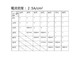
図1Cは、アノードおよびカソード間に流れる電流の密度が2.0A/cm2であるとき、セル温度およびガス露点のそれぞれが変化する場合におけるセルの過電圧の一例を示すテーブルである。FIG. 1C is a table showing an example of cell overvoltage when the cell temperature and the gas dew point each change when the density of the current flowing between the anode and the cathode is 2.0 A / cm 2 .
図1Dは、アノードおよびカソード間に流れる電流の密度が2.5A/cm2であるとき、セル温度およびガス露点のそれぞれが変化する場合におけるセルの過電圧の一例を示すテーブルである。FIG. 1D is a table showing an example of cell overvoltage when the cell temperature and the gas dew point each change when the density of the current flowing between the anode and the cathode is 2.5 A / cm 2 .
各テーブルでは、セル温度Tcとして、7つの代表温度(Tc=20℃、30℃、40℃、50℃、60℃、70℃、80℃)が取られ、ガス露点Tgとして、7つの代表温度(Tg=0℃、10℃、20℃、30℃、40℃、50℃、60℃)が取られ、これらの組合せのそれぞれにおけるセルの過電圧(mV)の測定結果が示されている。 In each table, seven representative temperatures (Tc = 20 ° C, 30 ° C, 40 ° C, 50 ° C, 60 ° C, 70 ° C, 80 ° C) are taken as the cell temperature Tc, and seven representative temperatures are taken as the gas dew point Tg. (Tg = 0 ° C., 10 ° C., 20 ° C., 30 ° C., 40 ° C., 50 ° C., 60 ° C.) are taken, and the measurement results of the cell overvoltage (mV) in each of these combinations are shown.
なお、各テーブルにおいて、セルの過電圧の測定結果が500mV以上である領域には、「X」印を付した。また、この「X」印の領域から、ガス露点を上昇させずに、セル温度Tcを上げる、または、セル温度を減少させずに、ガス露点を下げると、セルの電解質膜のドライアップが進行する。これにより、セルの触媒中のカーボン担体の腐食が進み、セルの触媒が劣化しやすくなるので、セルの過電圧測定を中止した。各テーブルでは、このような未測定領域を「-」印で示した。 In each table, the region where the measurement result of the overvoltage of the cell is 500 mV or more is marked with an “X”. Further, if the cell temperature Tc is raised without raising the gas dew point or the gas dew point is lowered without lowering the cell temperature from the region marked with "X", the dry-up of the electrolyte membrane of the cell proceeds. do. As a result, the carbon carrier in the catalyst of the cell is corroded, and the catalyst of the cell is liable to deteriorate. Therefore, the overvoltage measurement of the cell was stopped. In each table, such unmeasured areas are indicated by "-" marks.
なお、以上の実験条件などは、例示であって、本例に限定されない。 The above experimental conditions and the like are examples and are not limited to this example.
ここで、各テーブルの測定結果から理解できるとおり、アノードおよびカソード間に流れる電流の密度が低い条件(例えば、図1Aまたは図1B)では、ガス露点Tgおよびセル温度Tcが低い場合でも、セルの過電圧は、セルの触媒が劣化する領域(本実験では、500mV以上の領域)に至りにくいことが分かった。 Here, as can be understood from the measurement results of each table, under the condition that the density of the current flowing between the anode and the cathode is low (for example, FIG. 1A or FIG. 1B), even if the gas dew point Tg and the cell temperature Tc are low, the cell It was found that the overvoltage does not easily reach the region where the cell catalyst deteriorates (in this experiment, the region of 500 mV or more).
これに対して、アノードおよびカソード間に流れる電流の密度が高い条件(例えば、図1Cまたは図1D)では、ガス露点Tgおよびセル温度Tcが低いと、セルの過電圧は、セルが劣化する領域に至りやすいことが分かった。 On the other hand, under the condition that the density of the current flowing between the anode and the cathode is high (for example, FIG. 1C or FIG. 1D), when the gas dew point Tg and the cell temperature Tc are low, the overvoltage of the cell is in the region where the cell is deteriorated. It turned out to be easy to reach.
この実験結果は、上記のとおり、電解質膜のプロトン伝導度とセル温度Tcおよび電解質膜の含水率(ガス露点Tg)との間における正の相関性から推察することができる。つまり、ガス露点Tgおよびセル温度Tcが低いときは、電解質膜の抵抗が高くなる。しかし、電流と抵抗の積に相当するIR損失を含むセルの過電圧は、アノードおよびカソード間に流れる電流の密度が低い条件では、セルの触媒が劣化する領域に至らない場合が多い。逆に、アノードおよびカソード間に流れる電流の密度が高い条件では、上記のセルの過電圧は、セルの触媒が劣化する領域に至る場合が多い。 As described above, this experimental result can be inferred from the positive correlation between the proton conductivity of the electrolyte membrane and the cell temperature Tc and the water content (gas dew point Tg) of the electrolyte membrane. That is, when the gas dew point Tg and the cell temperature Tc are low, the resistance of the electrolyte membrane becomes high. However, the overvoltage of the cell including the IR loss corresponding to the product of the current and the resistance often does not reach the region where the catalyst of the cell is deteriorated under the condition that the density of the current flowing between the anode and the cathode is low. On the contrary, under the condition that the density of the current flowing between the anode and the cathode is high, the overvoltage of the above-mentioned cell often reaches the region where the catalyst of the cell is deteriorated.
このように、セル温度Tcおよびガス露点Tgが低いほど、アノードおよびカソード間に流れる電流を増加させるとき、セルの過電圧がセルの触媒が劣化する領域に至りやすい。換言すると、セル温度Tcおよびガス露点Tgが高いほど、アノードおよびカソード間に流れる電流を増加させても、セルの過電圧がセルの触媒が劣化する領域に至りにくい。 As described above, the lower the cell temperature Tc and the gas dew point Tg, the more likely it is that the overvoltage of the cell reaches the region where the catalyst of the cell deteriorates when the current flowing between the anode and the cathode is increased. In other words, the higher the cell temperature Tc and the gas dew point Tg, the less likely it is that the overvoltage of the cell will reach the region where the catalyst of the cell deteriorates even if the current flowing between the anode and the cathode is increased.
以上の測定結果によれば、セル温度Tcおよびガス露点Tgの少なくとも一方が低い状態から高い状態に上昇してから、アノードおよびカソード間に流れる電流を増加させる方が、これらが低い状態のまま、上記の電流を増加させる場合よりも、セルの触媒劣化を抑止する視点で適当であると考えられる。 According to the above measurement results, it is better to increase the current flowing between the anode and the cathode after at least one of the cell temperature Tc and the gas dew point Tg rises from a low state to a high state, while these remain low. It is considered to be more appropriate from the viewpoint of suppressing the deterioration of the catalyst of the cell than the case of increasing the above current.
すなわち、本開示の第1態様の電気化学式水素ポンプは、電解質膜、電解質膜の一方の主面に設けられたアノードおよび電解質膜の他方の主面に設けられたカソードを含むセルと、アノードとカソードとの間に電圧を印加する電圧印加器と、を備え、電圧印加器が、アノードとカソードとの間に電圧を印加することで、アノードに供給された水素含有ガス中の水素を、カソードに移動させ、かつ昇圧する電気化学式水素ポンプであって、アノードに供給される水素含有ガスの露点およびセルの温度の少なくとも一方が上昇すると、電圧印加器の印加電圧を制御して、アノードおよびカソード間を流れる電流を増加させる制御器を備える。 That is, the electrochemical hydrogen pump according to the first aspect of the present disclosure includes an anode, an anode provided on one main surface of the electrolyte membrane, and a cell including a cathode provided on the other main surface of the electrolyte membrane, and an anode. A voltage applicator that applies a voltage between the anode and the cathode is provided, and the voltage applicator applies a voltage between the anode and the cathode to obtain hydrogen in the hydrogen-containing gas supplied to the anode. It is an electrochemical hydrogen pump that moves to and boosts the voltage, and when at least one of the dew point of the hydrogen-containing gas supplied to the anode and the temperature of the cell rises, the applied voltage of the voltage applyer is controlled to control the anode and cathode. It is equipped with a controller that increases the current flowing between them.
かかる構成によると、本態様の電気化学式水素ポンプは、セルの劣化を従来よりも抑制し得る。 According to such a configuration, the electrochemical hydrogen pump of this embodiment can suppress the deterioration of the cell more than before.
例えば、電解質膜中の含水率と電解質膜内を移動するプロトン量とは正の相関関係があるので、アノードに供給される水素含有ガスの露点が低い状態のまま、アノードおよびカソード間を流れる電流を増加させると、セルの過電圧上昇によって、セルの触媒が劣化する可能性が高くなる。また、セルの温度と電解質膜内のプロトンの移動度とは正の相関関係があるので、セルの温度が低い状態のまま、上記の電流を増加させると、セルの過電圧上昇によって、セルの触媒が劣化する可能性が高くなる。 For example, since the water content in the electrolyte membrane and the amount of protons moving in the electrolyte membrane have a positive correlation, the current flowing between the anode and the cathode while the dew point of the hydrogen-containing gas supplied to the anode remains low. Increasing the number increases the possibility that the cell's anode will deteriorate due to the increase in cell overvoltage. In addition, since the cell temperature and the mobility of protons in the electrolyte membrane have a positive correlation, if the above current is increased while the cell temperature is low, the overvoltage rise of the cell causes the catalyst of the cell. Is more likely to deteriorate.
そこで、本態様の電気化学式水素ポンプは、アノードに供給される水素含有ガスの露点およびセルの温度の少なくとも一方が上昇してから、アノードおよびカソード間を流れる電流を増加させることで、これらが低い状態のまま、上記の電流を増加させる場合に比べて、セルの過電圧が、セルの触媒が劣化する領域に至る可能性を低減することができる。 Therefore, in the electrochemical hydrogen pump of this embodiment, at least one of the dew point of the hydrogen-containing gas supplied to the anode and the temperature of the cell rises, and then the current flowing between the anode and the cathode is increased, so that these are low. Compared to the case where the above current is increased in the state, the possibility that the overvoltage of the cell reaches the region where the catalyst of the cell is deteriorated can be reduced.
本開示の第2態様の電気化学式水素ポンプは、第1態様の電気化学式水素ポンプにおいて、制御器は、アノードに供給される水素含有ガスの露点が第1の閾値以上になると、電圧印加器の印加電圧を制御して、アノードおよびカソード間を流れる電流を増加させ、アノードに供給される水素含有ガスの露点が第1の閾値未満であるとき、電圧印加器の印加電圧を制御して、この電流を増加させない。 The electrochemical hydrogen pump of the second aspect of the present disclosure is the electrochemical hydrogen pump of the first aspect, and the controller is a voltage adapter when the dew point of the hydrogen-containing gas supplied to the anode becomes equal to or higher than the first threshold value. The applied voltage is controlled to increase the current flowing between the anode and the cathode, and when the dew point of the hydrogen-containing gas supplied to the anode is below the first threshold, the applied voltage of the voltage applyer is controlled to this. Does not increase the current.
かかる構成によると、本態様の電気化学式水素ポンプは、アノードに供給される水素含有ガスの露点と第1の閾値との比較に基づいて、アノードおよびカソード間を流れる電流の増減を適切に制御することで、セルの劣化を起こりにくく構成することができる。 According to such a configuration, the electrochemical hydrogen pump of this embodiment appropriately controls the increase / decrease of the current flowing between the anode and the cathode based on the comparison between the dew point of the hydrogen-containing gas supplied to the anode and the first threshold value. Therefore, it is possible to configure the cell so that deterioration of the cell is less likely to occur.
本開示の第3態様の電気化学式水素ポンプは、第1態様または第2態様の電気化学式水素ポンプにおいて、制御器は、セルの温度が、第2の閾値以上になると、電圧印加器の印加電圧を制御して、アノードおよびカソード間を流れる電流を増加させ、セルの温度が、第2の閾値未満であるとき、電圧印加器の印加電圧を制御して、この電流を増加させない。 The electrochemical hydrogen pump of the third aspect of the present disclosure is the electrochemical hydrogen pump of the first aspect or the second aspect, and the controller controls the applied voltage of the voltage applyer when the cell temperature becomes equal to or higher than the second threshold value. To increase the current flowing between the anode and cathode, and when the cell temperature is below the second threshold, control the applied voltage of the voltage applyer to not increase this current.
電気化学式水素ポンプでは、例えば、電解質膜の相対湿度およびアノードおよびカソード間を流れる電流の密度が一定であるようにポンプを制御するとき、セルの温度が上昇するに連れて、電解質膜のプロトン伝導度(電電率)が上がる。具体的には、セルの温度が所定の温度以上において、セルのIR損失が十分に低下する。なお、詳細は第2実施例で説明する。 In electrochemical hydrogen pumps, for example, when controlling the pump so that the relative humidity of the electrolyte membrane and the density of the current flowing between the anode and cathode are constant, the proton conduction of the electrolyte membrane as the cell temperature rises. The degree (electricity rate) goes up. Specifically, when the temperature of the cell is equal to or higher than a predetermined temperature, the IR loss of the cell is sufficiently reduced. The details will be described in the second embodiment.
よって、本態様の電気化学式水素ポンプは、セルのIR損失が十分に低下する第2の閾値以上において、アノードおよびカソード間を流れる電流を増加させることで、水素昇圧動作の効率を向上させることができる。 Therefore, the electrochemical hydrogen pump of this embodiment can improve the efficiency of the hydrogen boosting operation by increasing the current flowing between the anode and the cathode above the second threshold value at which the IR loss of the cell is sufficiently reduced. can.
また、本態様の電気化学式水素ポンプは、セルの温度と第2の閾値との比較に基づいて、アノードおよびカソード間を流れる電流の増減を適切に制御することで、セルの劣化を起こりにくく構成することができる。 Further, the electrochemical hydrogen pump of this embodiment is configured to prevent deterioration of the cell by appropriately controlling the increase / decrease of the current flowing between the anode and the cathode based on the comparison between the cell temperature and the second threshold value. can do.
本開示の第4態様の電気化学式水素ポンプは、第1態様から第3態様のいずれか一つの電気化学式水素ポンプにおいて、アノードに供給される水素含有ガスの露点を調整する露点調整器を備え、制御器は、露点調整器を制御して、アノードに供給される水素含有ガスの露点をセルの温度以下にしてもよい。 The electrochemical hydrogen pump of the fourth aspect of the present disclosure comprises a dew point adjuster for adjusting the dew point of the hydrogen-containing gas supplied to the anode in any one of the first to third aspects of the electrochemical hydrogen pump. The controller may control the dew point adjuster to bring the dew point of the hydrogen-containing gas supplied to the anode below the cell temperature.
かかる構成によると、本態様の電気化学式水素ポンプは、セルの劣化を従来よりも抑制し得る。 According to such a configuration, the electrochemical hydrogen pump of this embodiment can suppress the deterioration of the cell more than before.
具体的には、アノードに供給される水素含有ガスの露点がセルの温度よりも高いと、アノードで、水素含有ガス中の水蒸気が凝縮することによって、凝縮水による流路の閉塞(フラディング)が発生する可能性がある。そして、アノードのフラディングによって水素含有ガスの拡散性が阻害されることで、セルの過電圧の上昇を招く可能性がある。すると、セルの過電圧が、所定の電圧以上になるとき、セルの触媒中のカーボン担体の腐食が進み、セルが劣化しやすくなる。 Specifically, when the dew point of the hydrogen-containing gas supplied to the anode is higher than the cell temperature, the water vapor in the hydrogen-containing gas is condensed at the anode, so that the flow path is blocked (flooding) by the condensed water. May occur. Then, the diffusivity of the hydrogen-containing gas is hindered by the flooding of the anode, which may lead to an increase in the overvoltage of the cell. Then, when the overvoltage of the cell becomes equal to or higher than a predetermined voltage, the carbon carrier in the catalyst of the cell is corroded, and the cell is liable to deteriorate.
そこで、本態様の電気化学式水素ポンプは、アノードに供給される水素含有ガスの露点をセルの温度以下に制御することで、アノードのフラディング発生が抑制される。 Therefore, in the electrochemical hydrogen pump of this embodiment, the occurrence of flooding of the anode is suppressed by controlling the dew point of the hydrogen-containing gas supplied to the anode to be equal to or lower than the cell temperature.
本開示の第5態様の電気化学式水素ポンプは、第1態様から第4態様のいずれか一つの電気化学式水素ポンプにおいて、制御器は、電圧印加器の印加電圧を制御して、アノードおよびカソード間に流れる電流を0から所定値まで上昇させる期間において、上記の電流が低いほど、電流の上昇率を高くしてもよい。 The electrochemical hydrogen pump according to the fifth aspect of the present disclosure is the electrochemical hydrogen pump according to any one of the first to fourth aspects, in which the controller controls the applied voltage of the voltage applyer to control the voltage between the anode and the cathode. In the period in which the current flowing through the current is increased from 0 to a predetermined value, the lower the current is, the higher the rate of increase in the current may be.
かかる電圧制御の理由は、アノードおよびカソード間に流れる電流が低いほど、この電流の上昇率が高くても、セルの過電圧(IR損失分)が、セルの触媒が劣化する領域に至る可能性が低くなるからである。 The reason for such voltage control is that the lower the current flowing between the anode and the cathode, the higher the rate of increase of this current, but the overvoltage (IR loss) of the cell may reach the region where the catalyst of the cell deteriorates. Because it will be lower.
よって、本態様の電気化学式水素ポンプは、セルの劣化の適当な抑制およびセルの迅速な電流上昇を行うことができる。例えば、電気化学式水素ポンプの起動時に、セルの温度および電解質膜の含水率の両方が低いことが多い。しかし、この場合でも、アノードおよびカソード間に流れる電流が低いときは、セルの劣化を伴わずに電流の上昇率を高くすることができ、その結果、電気化学式水素ポンプを効率的に起動させることができる。 Therefore, the electrochemical hydrogen pump of this embodiment can appropriately suppress the deterioration of the cell and rapidly increase the current of the cell. For example, when starting an electrochemical hydrogen pump, both the cell temperature and the water content of the electrolyte membrane are often low. However, even in this case, when the current flowing between the anode and the cathode is low, the rate of increase in the current can be increased without deteriorating the cell, and as a result, the electrochemical hydrogen pump can be started efficiently. Can be done.
本開示の第6態様の電気化学式水素ポンプは、第1態様から第5態様のいずれか一つの電気化学式水素ポンプにおいて、アノードに供給される水素含有ガスの露点を調整する露点調整器を備え、制御器は、露点調整器を制御して、セルの温度の上昇に応じて、アノードに供給する水素含有ガスの露点を上昇させてもよい。 The sixth aspect of the present disclosure is an electrochemical hydrogen pump according to any one of the first to fifth aspects, comprising a dew point adjuster for adjusting the dew point of the hydrogen-containing gas supplied to the anode. The controller may control the dew point adjuster to raise the dew point of the hydrogen-containing gas supplied to the anode as the temperature of the cell rises.
かかる構成によると、本態様の電気化学式水素ポンプは、セルの温度の上昇に応じて、アノードに供給する水素含有ガスの露点を上昇させない場合に比べて、電解質膜がドライアップする可能性を低減することができる。 According to such a configuration, the electrochemical hydrogen pump of this embodiment reduces the possibility that the electrolyte membrane dries up as the temperature of the cell rises, as compared with the case where the dew point of the hydrogen-containing gas supplied to the anode is not raised. can do.
すなわち、本開示の第7態様の電気化学式水素ポンプの制御方法は、一対の主面を有する電解質膜のそれぞれの主面に設けられた、アノードとカソードとの間に電圧を印加することにより、前記アノードに供給された水素含有ガス中の水素を前記カソードに移動させ、圧縮された水素を生成するステップと、前記アノードに供給される水素含有ガスの露点および前記セルの温度の少なくとも一方が上昇すると、前記アノードと前記カソードとの間に印加する電圧を制御して、前記アノードおよび前記カソード間を流れる電流を増加させるステップを備える。 That is, the control method of the electrochemical hydrogen pump according to the seventh aspect of the present disclosure is to apply a voltage between the anode and the cathode provided on each main surface of the electrolyte membrane having a pair of main surfaces. At least one of the step of moving the hydrogen in the hydrogen-containing gas supplied to the anode to the cathode to generate compressed hydrogen, the dew point of the hydrogen-containing gas supplied to the anode, and the temperature of the cell rises. Then, the step of controlling the voltage applied between the anode and the cathode to increase the current flowing between the anode and the cathode is provided.
かかる構成によると、本態様の電気化学式水素ポンプの制御方法では、セルの劣化を従来よりも抑制し得る。 According to such a configuration, in the control method of the electrochemical hydrogen pump of this embodiment, deterioration of the cell can be suppressed more than before.
以下、添付図面を参照しながら、本開示の実施形態について説明する。なお、以下で説明する実施形態は、いずれも上記の各態様の一例を示すものである。よって、以下で示される形状、材料、構成要素、および、構成要素の配置位置および接続形態などは、あくまで一例であり、請求項に記載されていない限り、上記の各態様を限定するものではない。また、以下の構成要素のうち、上記の各態様の最上位概念を示す独立請求項に記載されていない構成要素については、任意の構成要素として説明される。また、図面において、同じ符号が付いたものは、説明を省略する場合がある。図面は理解しやすくするために、それぞれの構成要素を模式的に示したもので、形状および寸法比などについては正確な表示ではない場合がある。 Hereinafter, embodiments of the present disclosure will be described with reference to the accompanying drawings. In addition, all of the embodiments described below show an example of each of the above-mentioned embodiments. Therefore, the shapes, materials, components, the arrangement positions of the components, the connection form, and the like shown below are merely examples, and do not limit each of the above embodiments unless stated in the claims. .. Further, among the following components, the components not described in the independent claims indicating the top-level concept of each of the above embodiments will be described as arbitrary components. Further, in the drawings, those having the same reference numerals may omit the description. The drawings schematically show each component for the sake of easy understanding, and may not be an accurate display of the shape, dimensional ratio, and the like.
(第1実施形態)
[装置構成]
図2は、第1実施形態の電気化学式水素ポンプの一例を示す図である。(First Embodiment)
[Device configuration]
FIG. 2 is a diagram showing an example of an electrochemical hydrogen pump according to the first embodiment.
図2に示す例では、本実施形態の電気化学式水素ポンプ100は、セル70と、電圧印加器102と、制御器60と、を備える。
In the example shown in FIG. 2, the
なお、電気化学式水素ポンプ100は、複数のセル70を積層したスタックを含んでもよい。詳細は後で説明する。
The
セル70は、電解質膜11と、アノードANと、カソードCAと、を備える。
The
アノードANは、電解質膜11の一方の主面に設けられている。アノードANは、アノード触媒層およびアノードガス拡散層を含む電極である。カソードCAは、電解質膜11の他方の主面に設けられている。カソードCAは、カソード触媒層およびカソードガス拡散層を含む電極である。これにより、電解質膜11は、アノード触媒層およびカソード触媒層のそれぞれと接触するようにして、アノードANとカソードCAとによって挟持されている。
The anode AN is provided on one main surface of the
電解質膜11はプロトン伝導性を備える膜であれば、どのような構成であってもよい。例えば、電解質膜11として、フッ素系高分子電解質膜、炭化水素系電解質膜などを挙げることができる。具体的には、電解質膜11として、例えば、Nafion(登録商標、デュポン社製)、Aciplex(登録商標、旭化成株式会社製)などを用いることができるが、これらに限定されない。
The
アノード触媒層は、電解質膜11の一方の主面に設けられている。アノード触媒層は、触媒金属(例えば、白金)を分散状態で担持することができるカーボンを含むが、これに限定されない。
The anode catalyst layer is provided on one main surface of the
カソード触媒層は、電解質膜11の他方の主面に設けられている。カソード触媒層は、触媒金属(例えば、白金)を分散状態で担持することができるカーボンを含むが、これに限定されない。
The cathode catalyst layer is provided on the other main surface of the
カソード触媒層もアノード触媒層も、触媒の調製方法としては、種々の方法を挙げることができるが、特に限定されない。例えば、カーボン系粉末としては、黒鉛、カーボンブラック、導電性を有する活性炭などの粉末を挙げることができる。カーボン担体に、白金若しくは他の触媒金属を担持する方法は、特に限定されない。例えば、粉末混合または液相混合などの方法を用いてもよい。後者の液相混合としては、例えば、触媒成分コロイド液にカーボンなどの担体を分散させ、吸着させる方法などが挙げられる。白金などの触媒金属のカーボン担体への担持状態は、特に限定されない。例えば、触媒金属を微粒子化し、高分散で担体に担持してもよい。 As for the cathode catalyst layer and the anode catalyst layer, various methods can be mentioned as a method for preparing the catalyst, but the method is not particularly limited. For example, examples of the carbon-based powder include powders such as graphite, carbon black, and conductive activated carbon. The method of supporting platinum or other catalytic metal on the carbon carrier is not particularly limited. For example, a method such as powder mixing or liquid phase mixing may be used. Examples of the latter liquid phase mixing include a method in which a carrier such as carbon is dispersed in a colloidal liquid as a catalyst component and adsorbed. The supported state of the catalyst metal such as platinum on the carbon carrier is not particularly limited. For example, the catalyst metal may be atomized and supported on a carrier with high dispersion.
カソードガス拡散層は、カソード触媒層上に設けられている。カソードガス拡散層は、多孔性材料で構成され、導電性およびガス拡散性を備える。カソードガス拡散層は、電気化学式水素ポンプ100の動作時にカソードCAおよびアノードAN間の差圧で発生する構成部材の変位、変形に適切に追従するような弾性を備える方が望ましい。カソードガス拡散層の基材として、例えば、カーボン繊維焼結体などを使用することができるが、これに限定されない。
The cathode gas diffusion layer is provided on the cathode catalyst layer. The cathode gas diffusion layer is made of a porous material and has conductivity and gas diffusivity. It is desirable that the cathode gas diffusion layer has elasticity so as to appropriately follow the displacement and deformation of the constituent members generated by the differential pressure between the cathode CA and the anode AN during the operation of the
アノードガス拡散層は、アノード触媒層上に設けられている。アノードガス拡散層は、多孔性材料で構成され、導電性およびガス拡散性を備える。アノードガス拡散層は、電気化学式水素ポンプ100の動作時に、上記の差圧による電解質膜11の押し付けに耐え得る程度の剛性を備える方が望ましい。アノードガス拡散層の基材として、例えば、カーボン粒子焼結体などを使用することができるが、これに限定されない。
The anode gas diffusion layer is provided on the anode catalyst layer. The anode gas diffusion layer is made of a porous material and has conductivity and gas diffusivity. It is desirable that the anode gas diffusion layer has a rigidity sufficient to withstand the pressing of the
電圧印加器102は、アノードANとカソードCAとの間に電圧を印加する装置である。電圧印加器102は、アノードANとカソードCAとの間に電圧を印加することができれば、どのような構成であってもよい。図2に示す例では、電圧印加器102の高電位側端子が、アノードANに接続され、電圧印加器102の低電位側端子が、カソードCAに接続されている。これにより、電圧印加器102を用いて、アノードANおよびカソードCAの間で通電が行われる。すると、本実施形態の電気化学式水素ポンプ100は、電圧印加器102が、アノードANとカソードCAとの間に電圧を印加することで、アノードANに供給された水素含有ガス中の水素を、カソードCAに移動させ、かつ昇圧する。
The
なお、電圧印加器102として、例えば、DC/DCコンバータ、AC/DCコンバータなどを挙げることができる。DC/DCコンバータは、電圧印加器102が、太陽電池、燃料電池、バッテリなどの直流電源と接続された場合に用いられる。AC/DCコンバータは、電圧印加器102が、商用電源などの交流電源と接続された場合に用いられる。
Examples of the
また、電圧印加器102は、例えば、セル70に供給する電力が所定の設定値となるように、アノードANおよびカソードCA間に印加される電圧、アノードANおよびカソードCA間に流れる電流が調整される電力型電源であってもよい。
Further, in the
制御器60は、アノードANに供給される水素含有ガスの露点およびセル70の温度の少なくとも一方が上昇すると、電圧印加器102の印加電圧を制御して、アノードANおよびカソードCA間を流れる電流を増加させる。
When at least one of the dew point of the hydrogen-containing gas supplied to the anode AN and the temperature of the
制御器60は、例えば、演算回路(図示せず)と、制御プログラムを記憶する記憶回路(図示せず)と、を備える。演算回路として、例えば、MPU、CPUなどを挙げることができる。記憶回路として、例えば、メモリなどを挙げることができる。制御器60は、集中制御を行う単独の制御器で構成されていてもよいし、互いに協働して分散制御を行う複数の制御器で構成されていてもよい。
The
なお、図1には示されていないが、電気化学式水素ポンプ100の水素昇圧動作において必要となる部材および機器は適宜、設けられる。
Although not shown in FIG. 1, members and equipment necessary for the hydrogen boosting operation of the
例えば、一対のセパレータのそれぞれが、セル70のアノードANおよびカソードCAのそれぞれを外側から挟んでいてもよい。この場合、アノードANに接触するセパレータは、アノードANに水素含有ガスを供給するための導電性の板状の部材である。この板状の部材は、アノードANに供給する水素含有ガスが流れるガス流路を備える。カソードCAに接触するセパレータは、カソードCAから水素を導出するための導電性の板状の部材である。この板状の部材は、カソードCAから導出した水素が流れるガス流路を備える。これらのガス流路は、セパレータと別に設けることもできるが、セパレータの表面にガス流路の溝を、例えば、サーペンタイン状に形成することが一般的である。
For example, each of the pair of separators may sandwich each of the anode AN and the cathode CA of the
また、電気化学式水素ポンプ100では、通常、高圧の水素が外部へリークしないように、セル70の両側からガスケットなどのシール材が設けられ、セル70と一体化して予め組み立てられる。そして、セル70の外側には、これを機械的に固定するとともに、隣接するセル70同士を互いに電気的に直列に接続するための上記のセパレータが配置されている。
Further, in the
セル70とセパレータを交互に重ねて、セル70を10~200個程度、積層して、その積層体(スタック)を、集電板および絶縁板を介して端板で挟み、両端板を締結ロッドで締め付けるのが一般的な積層構造である。なお、この場合、セパレータのそれぞれのガス流路に適量の水素含有ガスを供給するには、セパレータのそれぞれにおいて、適宜の管路から溝状の分岐経路を分岐させ、これらの下流端が、セパレータのそれぞれのガス流路に連結するように構成する必要がある。このような管路のことをマニホールドといい、このマニホールドは、セパレータのそれぞれの適所に設けられた貫通孔の連なりにより構成されている。
The
また、電気化学式水素ポンプ100には、セル70の温度を検知する温度検知器、セル70の温度を調整する温度調整器、アノードANに供給される水素含有ガスの露点を調整する露点調整器などが設けられていてもよい。なお、露点調整器の詳細は、第2実施形態で説明する。
Further, the
温度検知器として、例えば、熱電対、サーミスタなどを挙げることができるが、これらに限定されない。 Examples of the temperature detector include, but are not limited to, a thermocouple, a thermistor, and the like.
また、温度調整器として、例えば、セパレータに形成された流路に適温の熱媒体を循環させる装置などを挙げることができるが、これに限定されない。温度調整器は、セル70を加熱する加熱器(例えば、電気ヒータ)とセル70を冷却する冷却器(例えば、冷却ファン)との組合せであってもよい。 Further, examples of the temperature regulator include, but are not limited to, a device for circulating a heat medium having an appropriate temperature in a flow path formed in a separator. The temperature controller may be a combination of a heater that heats the cell 70 (for example, an electric heater) and a cooler that cools the cell 70 (for example, a cooling fan).
なお、以上の図示しない部材および機器は例示であって、本例に限定されない。 The members and devices (not shown above) are examples and are not limited to this example.
[動作]
以下、電気化学式水素ポンプ100の水素昇圧動作の一例について、図面を参照しながら説明する。[motion]
Hereinafter, an example of the hydrogen boosting operation of the
以下の動作は、例えば、制御器60の演算回路が、制御器60の記憶回路から制御プログラムを読み出すことにより行われてもよい。ただし、以下の動作を制御器60で行うことは、必ずしも必須ではない。操作者が、その一部の動作を行ってもよい。
The following operation may be performed, for example, by the arithmetic circuit of the
まず、電気化学式水素ポンプ100のアノードANに低圧の水素含有ガスが供給されるとともに、電圧印加器102の電圧が電気化学式水素ポンプ100に給電される。
First, a low-pressure hydrogen-containing gas is supplied to the anode AN of the
すると、アノードANのアノード触媒層において、水素分子がプロトンと電子とに分離する(式(1))。プロトンは電解質膜11内を伝導してカソード触媒層に移動する。電子は電圧印加器102を通じてカソード触媒層に移動する。
Then, in the anode catalyst layer of the anode AN, hydrogen molecules are separated into protons and electrons (Equation (1)). Protons conduct in the
そして、カソード触媒層において、水素分子が再び生成される(式(2))。なお、プロトンが電解質膜11中を伝導する際に、所定水量の水が、電気浸透水としてアノードANからカソードCAにプロトンと同伴して移動することが知られている。
Then, hydrogen molecules are generated again in the cathode catalyst layer (Equation (2)). It is known that when protons conduct through the
このとき、図示しない流量調整器を用いて、水素導出経路の圧損を増加させることにより、カソードCAで生成された水素(H2)を昇圧することができる。なお、流量調整器として、例えば、水素導出経路に設けられた背圧弁、調整弁などを挙げることができる。この場合、水素導出経路の圧損を増加させるとは、水素導出経路に設けられた背圧弁、調整弁の開度を小さくすることに対応する。At this time, hydrogen (H 2 ) generated by the cathode CA can be boosted by increasing the pressure loss of the hydrogen derivation path by using a flow rate regulator (not shown). Examples of the flow rate regulator include a back pressure valve and a regulating valve provided in the hydrogen derivation path. In this case, increasing the pressure loss of the hydrogen derivation path corresponds to reducing the opening degree of the back pressure valve and the regulating valve provided in the hydrogen derivation path.
アノード:H2(低圧)→2H++2e- ・・・(1)
カソード:2H++2e-→H2(高圧) ・・・(2)
このようにして、電圧印加器102が上記の電圧を印加することで、アノードANに供給される水素含有ガス中の水素がカソードCAにおいて昇圧される電気化学式水素ポンプ100の水素昇圧動作が行われる。そして、この水素昇圧動作では、アノードANに供給される水素含有ガスの露点およびセル70の温度の少なくとも一方が上昇すると、アノードANおよびCAカソード間を流れる電流を増加させるように、電圧印加器102の印加電圧が制御される。Anode: H 2 (low pressure) → 2H + + 2e -... ( 1)
Cathode: 2H + + 2e- → H 2 (high voltage) ・ ・ ・ (2)
In this way, when the
なお、カソードCAで昇圧された水素は、例えば、図示しない水素貯蔵器に一時的に貯蔵される。また、水素貯蔵器で貯蔵された水素は、適時に、水素需要体に供給される。水素需要体として、例えば、水素を用いて発電する燃料電池などを挙げることができる。 The hydrogen boosted by the cathode CA is temporarily stored in, for example, a hydrogen reservoir (not shown). Further, the hydrogen stored in the hydrogen reservoir is supplied to the hydrogen demander in a timely manner. Examples of hydrogen demanders include fuel cells that generate electricity using hydrogen.
以上のとおり、本実施形態の電気化学式水素ポンプ100は、セル70の劣化を従来よりも抑制し得る。
As described above, the
例えば、電解質膜11中の含水率と電解質膜11内を移動するプロトン量とは正の相関関係があるので、アノードANに供給される水素含有ガスの露点が低い状態のまま、アノードANおよびCAカソード間を流れる電流を増加させると、セル70の過電圧上昇によって、セル70の触媒が劣化する可能性が高くなる。また、セル70の温度と電解質膜11内のプロトンの移動度とは正の相関関係があるので、セル70の温度が低い状態のまま、上記の電流を増加させると、セル70の過電圧上昇によって、セル70の触媒が劣化する可能性が高くなる。
For example, since the water content in the
そこで、本実施形態の電気化学式水素ポンプ100は、アノードANに供給される水素含有ガスの露点およびセル70の温度の少なくとも一方が上昇してから、アノードANおよびカソードCA間を流れる電流を増加させることで、これらが低い状態のまま、上記の電流を増加させる場合に比べて、セルの過電圧が、セル70の触媒が劣化する領域に至る可能性を低減することができる。
Therefore, the
(第1実施例)
第1実施例の電気化学式水素ポンプ100は、以下に説明する制御器60の制御内容以外は、第1実施形態の電気化学式水素ポンプ100と同様である。(First Example)
The
制御器60は、アノードANに供給される水素含有ガスの露点が第1の閾値以上になると、電圧印加器102の印加電圧を制御して、アノードANおよびカソードCA間を流れる電流を増加させ、アノードANに供給される水素含有ガスの露点が第1の閾値未満であるとき、電圧印加器102の印加電圧を制御して、この電流を増加させない。
When the dew point of the hydrogen-containing gas supplied to the anode AN becomes equal to or higher than the first threshold value, the
なお、第1の閾値は、例えば、電気化学式水素ポンプが昇圧する水素量などの運転条件をもとに、図1A-図1Dに記載のテーブルなどを参酌することにより、電気化学式水素ポンプのセルの劣化が起こりにくい適宜の値に設定することができる。 The first threshold value is, for example, the cell of the electrochemical hydrogen pump by referring to the table shown in FIGS. 1A-1D based on the operating conditions such as the amount of hydrogen boosted by the electrochemical hydrogen pump. It can be set to an appropriate value that is less likely to cause deterioration.
以上により、本実施例の電気化学式水素ポンプ100は、アノードANに供給される水素含有ガスの露点と第1の閾値との比較に基づいて、アノードANおよびカソードCA間を流れる電流の増減を適切に制御することで、セル70の劣化を起こりにくく構成することができる。
Based on the above, the
本実施例の電気化学式水素ポンプ100は、上記の特徴以外は、第1実施形態の電気化学式水素ポンプ100と同様であってもよい。
The
(第2実施例)
第2実施例の電気化学式水素ポンプ100は、以下に説明する制御器60の制御内容以外は、第1実施形態の電気化学式水素ポンプ100と同様である。(Second Example)
The
図3は、セルの温度と、電解質膜のプロトン伝導度(導電率)およびセルのIR損失との間の相関関係の一例を示す図である。図3の横軸に、セル70の温度が取られている。また、図3の左側の縦軸に、電解質膜11のプロトン伝導度が取られ、右側の縦軸に、セル70のIR損失が取られている。なお、図3には、電解質膜11の相対湿度およびアノードANおよびカソードCA間を流れる電流の密度が一定である場合における上記の相関関係が示されている。例えば、セル70の温度が増減するに連れて、水素含有ガスの露点を増減させることで、電解質膜11の相対湿度を一定に維持することができる。
FIG. 3 is a diagram showing an example of the correlation between the cell temperature, the proton conductivity (conductivity) of the electrolyte membrane, and the IR loss of the cell. The temperature of the
図3から理解できるとおり、電気化学式水素ポンプ100では、例えば、電解質膜11の相対湿度およびアノードANおよびカソードCA間を流れる電流の密度が一定であるようにポンプを制御するとき、セル70の温度が上昇するに連れて、電解質膜11のプロトン伝導度(電電率)が上がる。具体的には、セル70の温度が所定の温度以上において、セル70のIR損失が十分に低下することが分かる。
As can be seen from FIG. 3, in the
そこで、制御器60は、セル70の温度が、第2の閾値以上になると、電圧印加器102の印加電圧を制御して、アノードANおよびカソードCA間を流れる電流を増加させ、セル70の温度が、第2の閾値未満であるとき、電圧印加器102の印加電圧を制御して、この電流を増加させない。
Therefore, when the temperature of the
以上により、本実施例の電気化学式水素ポンプ100は、セル70のIR損失が十分に低下する第2の閾値以上において、アノードANおよびカソードCA間を流れる電流を増加させることで、水素昇圧動作の効率を向上させることができる。この場合、第2の閾値は、例えば、電気化学式水素ポンプが昇圧する水素量などの運転条件をもとに、セル70の温度とセル70のIR損失との間の相関関係などを参酌することにより、電気化学式水素ポンプ100の水素昇圧動作の効率が向上する適宜の値に設定することができる。
As described above, the
また、本実施例の電気化学式水素ポンプ100は、セル70の温度と第2の閾値との比較に基づいて、アノードANおよびカソードCA間を流れる電流の増減を適切に制御することで、セル70の劣化を起こりにくく構成することができる。この場合、第2の閾値は、例えば、電気化学式水素ポンプが昇圧する水素量などの運転条件をもとに、図1A-図1Dに記載のテーブルなどを参酌することにより、電気化学式水素ポンプのセルの劣化が起こりにくい適宜の値に設定することができる。
Further, the
本実施例の電気化学式水素ポンプ100は、上記の特徴以外は、第1実施形態または第1実施形態の第1実施例の電気化学式水素ポンプ100と同様であってもよい。
The
(第3実施例)
第3実施例の電気化学式水素ポンプ100は、以下に説明する制御器60の制御内容以外は、第1実施形態の電気化学式水素ポンプ100と同様である。(Third Example)
The
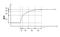
図4は、第1実施形態の第3実施例の電気化学式水素ポンプにおけるアノードおよびカソード間を流れる電流の制御の一例を示す図である。 FIG. 4 is a diagram showing an example of control of the current flowing between the anode and the cathode in the electrochemical hydrogen pump of the third embodiment of the first embodiment.
本実施例の電気化学式水素ポンプでは、一例として、図4に示す如く、起動時におけるアノードANおよびカソードCA間に流れる電流を0から所定値まで上昇させる期間を、n個のサブ期間(s1、s2、・・・、sn:nは自然数)に区分し、n個のサブ期間それぞれにおける電流の増分をf1、f2、・・・、fn(nは自然数)とする。そして、このようなn個のサブ期間から選ばれたサブ期間(sx)に対応する電流の増分(fx)と、選ばれたサブ期間(sx)とから求まるn個の比率をrx(rx=fx/sx:xは1≦x≦nで示される自然数)とする。そして、n個の比率rxから選ばれた任意の2つの比率のうち、電流が低い方を第1比率、電流が高い方を第2比率と定義するとき、第2比率が第1比率よりも小さくなるように、電圧印加器102の印加電圧を制御する。つまり、比率rを、r=f1/s1≧f2/s2≧f3/s3≧f4/s4・・・と設定することで、電流の時間変化が、起動の開始時からの時間の経過とともに緩やかになるように、電圧印加器102の印加電圧を制御する。
In the electrochemical hydrogen pump of this embodiment, as an example, as shown in FIG. 4, the period for increasing the current flowing between the anode AN and the cathode CA at the time of starting from 0 to a predetermined value is set to n sub-periods (s1, It is divided into s2, ..., Sn: n is a natural number), and the current increments in each of the n sub-periods are f1, f2, ..., Fn (n is a natural number). Then, the ratio of n pieces obtained from the current increment (fx) corresponding to the sub-period (sx) selected from such n sub-periods and the selected sub-period (sx) is rx (rx = = fx / sx: x is a natural number represented by 1 ≦ x ≦ n). Then, when the one with the lower current is defined as the first ratio and the one with the higher current is defined as the second ratio among any two ratios selected from the n ratios rx, the second ratio is larger than the first ratio. The applied voltage of the
このように、本実施例の電気化学式水素ポンプ100では、制御器60は、電圧印加器102の印加電圧を制御して、アノードANおよびカソードCA間に流れる電流を0から所定値まで上昇させる期間において、上記の電流が低いほど、電流の上昇率を高くする。
As described above, in the
かかる電圧制御の理由は、アノードANおよびカソードCA間に流れる電流が低いほど、この電流の上昇率が高くても、セル70の過電圧(IR損失分)が、セル70の触媒が劣化する領域に至る可能性が低くなるからである。
The reason for such voltage control is that the lower the current flowing between the anode AN and the cathode CA, the higher the rate of increase in this current, but the overvoltage (IR loss) of the
これにより、本実施例の電気化学式水素ポンプ100は、セル70の劣化の適当な抑制およびセル70の迅速な電流上昇を行うことができる。例えば、電気化学式水素ポンプ100の起動時に、セル70の温度および電解質膜11の含水率の両方が低いことが多い。しかし、この場合でも、アノードANおよびカソードCA間に流れる電流が低いときは、セル70の劣化を伴わずに電流の上昇率を高くすることができ、その結果、電気化学式水素ポンプ100を効率的に起動させることができる。
As a result, the
本実施例の電気化学式水素ポンプ100は、上記の特徴以外は、第1実施形態および第1実施形態の第1実施例-第2実施例のいずれかの電気化学式水素ポンプ100と同様であってもよい。
The
(第2実施形態)
図5は、第2実施形態の電気化学式水素ポンプの一例を示す図である。(Second Embodiment)
FIG. 5 is a diagram showing an example of an electrochemical hydrogen pump according to the second embodiment.
図5に示す例では、本実施形態の電気化学式水素ポンプ100は、セル70と、電圧印加器102と、露点調整器110と、制御器60と、を備える。
In the example shown in FIG. 5, the
ここで、セル70および電圧印加器102は第1実施形態と同様であるので説明を省略する。
Here, since the
露点調整器110は、アノードANに供給される水素含有ガスの露点を調整する装置である。露点調整器110は、このような水素含有ガスの露点を調整することができれば、どのような構成であってもよい。
The
例えば、露点調整器110は、水素含有ガスを加湿する加湿器を備えてもよい。加湿器として、例えば、水素含有ガスを温水に通気して加湿するバブラー構成の加湿器、水素含有ガスを透湿膜で加湿する構成の加湿器などを挙げることができる。なお、露点調整器110が、上記のバブラー構成の加湿器を備える場合、温水の温度により、水素含有ガスの露点を適宜、調整することができる。
For example, the
また、露点調整器110は、アノードANから排出される高加湿状態の水素含有ガスと、外部の水素供給源から供給される低加湿状態の水素含有ガスとを混合することで、混合ガスの露点を調整する混合器であってもよい。このとき、外部の水素供給源の水素含有ガスは、例えば、水電解装置で生成されてもよい。
Further, the
制御器60は、露点調整器110を制御して、アノードANに供給される水素含有ガスの露点をセル70の温度以下にする。
The
以上により、本実施形態の電気化学式水素ポンプ100は、セル70の劣化を従来よりも抑制し得る。具体的には、アノードANに供給される水素含有ガスの露点がセル70の温度よりも高いと、アノードANで、水素含有ガス中の水蒸気が凝縮することによって、凝縮水による流路の閉塞(フラディング)が発生する可能性がある。そして、アノードANのフラディングによって水素含有ガスの拡散性が阻害されることで、セル70の過電圧の上昇を招く可能性がある。すると、セル70の過電圧が、所定の電圧以上になるとき、セル70の触媒中のカーボン担体の腐食が進み、セル70が劣化しやすくなる。
As described above, the
そこで、本実施形態の電気化学式水素ポンプ100は、アノードANに供給される水素含有ガスの露点をセル70の温度以下に制御することで、アノードANのフラディング発生が抑制される。
Therefore, in the
本実施形態の電気化学式水素ポンプ100は、上記の特徴以外は、第1実施形態および第1実施形態の第1実施例-第3実施例のいずれかの電気化学式水素ポンプ100と同様であってもよい。
The
(変形例)
本変形例の電気化学式水素ポンプ100は、以下に説明する制御器60の制御内容以外は、第2実施形態の電気化学式水素ポンプ100と同様である。(Modification example)
The
制御器60は、露点調整器110を制御して、セル70の温度の上昇に応じて、アノードANに供給する水素含有ガスの露点を上昇させる。
The
以上により、本変形例の電気化学式水素ポンプ100は、セル70の温度の上昇に応じて、アノードANに供給する水素含有ガスの露点を上昇させない場合に比べて、電解質膜11がドライアップする可能性を低減することができる。
As described above, in the
本変形例の電気化学式水素ポンプ100は、上記の特徴以外は、第1実施形態、第1実施形態の第1実施例-第3実施例および第2実施形態のいずれかの電気化学式水素ポンプ100と同様であってもよい。
The
なお、第1実施形態、第1実施形態の第1実施例-第3実施例、第2実施形態および第2実施形態の変形例は、互いに相手を排除しない限り、互いに組み合わせても構わない。 The first embodiment, the first embodiment-3rd embodiment, the second embodiment, and the modified examples of the second embodiment may be combined with each other as long as the other party is not excluded from each other.
上記説明から、当業者にとっては、本開示の多くの改良および他の実施形態が明らかである。従って、上記説明は、例示としてのみ解釈されるべきであり、本開示を実行する最良の態様を当業者に教示する目的で提供されたものである。本開示の精神を逸脱することなく、その構造および/または機能の詳細を実質的に変更することができる。 From the above description, many improvements and other embodiments of the present disclosure will be apparent to those of skill in the art. Accordingly, the above description should be construed as an example only and is provided for the purpose of teaching those skilled in the art the best aspects of carrying out the present disclosure. The details of its structure and / or function may be substantially modified without departing from the spirit of the present disclosure.
本開示の一態様は、セルの劣化を従来よりも抑制し得る電気化学式水素ポンプに利用することができる。 One aspect of the present disclosure can be used for an electrochemical hydrogen pump capable of suppressing deterioration of a cell more than before.
11 :電解質膜
60 :制御器
70 :セル
100 :電気化学式水素ポンプ
102 :電圧印加器
110 :露点調整器
AN :アノード
CA :カソード11: Electrolyte membrane 60: Controller 70: Cell 100: Electrochemical hydrogen pump 102: Voltage applyer 110: Dew point adjuster AN: Anode CA: Cathode
Claims (5)
前記電圧印加器が前記電圧を印加することで、前記アノードに供給された水素含有ガス中の水素を、前記カソードに移動させ、かつ昇圧する電気化学式水素ポンプであって、
前記アノードに供給される水素含有ガスの露点が所定の閾値以上になると、前記電圧印加器の印加電圧を制御して、前記アノードおよび前記カソード間を流れる電流を増加させ、前記アノードに供給される水素含有ガスの露点が前記所定の閾値未満であるとき、前記電圧印加器の印加電圧を制御して、前記電流を増加させない制御器を備える電気化学式水素ポンプ。 A voltage application that applies a voltage between the anode and the cathode, and a cell including an electrolyte membrane, an anode provided on one main surface of the electrolyte membrane, and a cathode provided on the other main surface of the electrolyte membrane. Equipped with a vessel,
An electrochemical hydrogen pump that moves hydrogen in a hydrogen-containing gas supplied to the anode to the cathode and boosts the voltage by applying the voltage to the voltage applyer.
When the dew point of the hydrogen-containing gas supplied to the anode becomes equal to or higher than a predetermined threshold value , the applied voltage of the voltage applyer is controlled to increase the current flowing between the anode and the cathode, and the current is supplied to the anode. An electrochemical hydrogen pump comprising a controller that controls the applied voltage of the voltage applyer and does not increase the current when the dew point of the hydrogen-containing gas is less than the predetermined threshold value .
前記制御器は、前記露点調整器を制御して、前記アノードに供給される水素含有ガスの露点を前記セルの温度以下にする請求項1に記載の電気化学式水素ポンプ。 A dew point adjuster for adjusting the dew point of the hydrogen-containing gas supplied to the anode is provided.
The electrochemical hydrogen pump according to claim 1 , wherein the controller controls the dew point adjuster to bring the dew point of the hydrogen-containing gas supplied to the anode to the temperature of the cell or lower.
前記制御器は、前記露点調整器を制御して、前記セルの温度の上昇に応じて、前記アノードに供給する水素含有ガスの露点を上昇させる請求項1-3のいずれか1項に記載の電気化学式水素ポンプ。 A dew point adjuster for adjusting the dew point of the hydrogen-containing gas supplied to the anode is provided.
The controller according to any one of claims 1 to 3 , wherein the controller controls the dew point adjuster to raise the dew point of the hydrogen-containing gas supplied to the anode in response to an increase in the temperature of the cell. Electrochemical hydrogen pump.
Applications Claiming Priority (3)
| Application Number | Priority Date | Filing Date | Title |
|---|---|---|---|
| JP2019232399 | 2019-12-24 | ||
| JP2019232399 | 2019-12-24 | ||
| PCT/JP2020/040479 WO2021131312A1 (en) | 2019-12-24 | 2020-10-28 | Electrochemical hydrogen pump and control method therefor |
Publications (2)
| Publication Number | Publication Date |
|---|---|
| JPWO2021131312A1 JPWO2021131312A1 (en) | 2021-07-01 |
| JP7002044B2 true JP7002044B2 (en) | 2022-02-04 |
Family
ID=76574053
Family Applications (1)
| Application Number | Title | Priority Date | Filing Date |
|---|---|---|---|
| JP2021531738A Active JP7002044B2 (en) | 2019-12-24 | 2020-10-28 | Electrochemical hydrogen pump and its control method |
Country Status (5)
| Country | Link |
|---|---|
| US (1) | US20220025529A1 (en) |
| EP (1) | EP4083266A1 (en) |
| JP (1) | JP7002044B2 (en) |
| CN (1) | CN113366152A (en) |
| WO (1) | WO2021131312A1 (en) |
Families Citing this family (2)
| Publication number | Priority date | Publication date | Assignee | Title |
|---|---|---|---|---|
| JP6765060B1 (en) * | 2018-11-05 | 2020-10-07 | パナソニックIpマネジメント株式会社 | How to operate the electrochemical hydrogen compressor and the electrochemical hydrogen compressor |
| FR3136780A1 (en) * | 2022-06-16 | 2023-12-22 | H2Gremm | Hydrogen production process with adjustment of the power of a compressor |
Citations (8)
| Publication number | Priority date | Publication date | Assignee | Title |
|---|---|---|---|---|
| US20090136790A1 (en) | 2007-11-13 | 2009-05-28 | Schrieber Jeffrey W | Regulating An Oxidizer In An Electrochemical Cell Pumping System |
| JP2017529460A (en) | 2014-07-02 | 2017-10-05 | ヌヴェラ・フュエル・セルズ,エルエルシー | Multi-stack electrochemical compressor system and method of operation |
| JP2017530921A (en) | 2014-07-03 | 2017-10-19 | ヌヴェラ・フュエル・セルズ,エルエルシー | System and method for regenerating an absorbent bed for drying compressed wet hydrogen |
| WO2018033948A1 (en) | 2016-08-18 | 2018-02-22 | 株式会社 東芝 | Hydrogen production system and electrolytic cell stack control method |
| JP2018165386A (en) | 2017-03-28 | 2018-10-25 | 東京瓦斯株式会社 | Compressed hydrogen production system |
| JP2019014644A (en) | 2017-07-05 | 2019-01-31 | パナソニックIpマネジメント株式会社 | Hydrogen supply system |
| JP2019031700A (en) | 2017-08-04 | 2019-02-28 | パナソニックIpマネジメント株式会社 | Hydrogen supply system |
| JP2019183258A (en) | 2018-04-16 | 2019-10-24 | パナソニックIpマネジメント株式会社 | Electrochemical hydrogen pump and operation method of electrochemical hydrogen pump |
Family Cites Families (3)
| Publication number | Priority date | Publication date | Assignee | Title |
|---|---|---|---|---|
| US4483748A (en) * | 1982-09-20 | 1984-11-20 | Olin Corporation | Automated membrane test cell apparatus and method for so using |
| US4620914A (en) * | 1985-07-02 | 1986-11-04 | Energy Research Corporation | Apparatus for purifying hydrogen |
| JP6299027B2 (en) | 2013-12-16 | 2018-03-28 | 国立大学法人山梨大学 | Hydrogen refining pressurization system and operation method thereof |
-
2020
- 2020-10-28 CN CN202080012135.3A patent/CN113366152A/en active Pending
- 2020-10-28 WO PCT/JP2020/040479 patent/WO2021131312A1/en unknown
- 2020-10-28 EP EP20906188.6A patent/EP4083266A1/en active Pending
- 2020-10-28 JP JP2021531738A patent/JP7002044B2/en active Active
-
2021
- 2021-10-11 US US17/498,314 patent/US20220025529A1/en active Pending
Patent Citations (8)
| Publication number | Priority date | Publication date | Assignee | Title |
|---|---|---|---|---|
| US20090136790A1 (en) | 2007-11-13 | 2009-05-28 | Schrieber Jeffrey W | Regulating An Oxidizer In An Electrochemical Cell Pumping System |
| JP2017529460A (en) | 2014-07-02 | 2017-10-05 | ヌヴェラ・フュエル・セルズ,エルエルシー | Multi-stack electrochemical compressor system and method of operation |
| JP2017530921A (en) | 2014-07-03 | 2017-10-19 | ヌヴェラ・フュエル・セルズ,エルエルシー | System and method for regenerating an absorbent bed for drying compressed wet hydrogen |
| WO2018033948A1 (en) | 2016-08-18 | 2018-02-22 | 株式会社 東芝 | Hydrogen production system and electrolytic cell stack control method |
| JP2018165386A (en) | 2017-03-28 | 2018-10-25 | 東京瓦斯株式会社 | Compressed hydrogen production system |
| JP2019014644A (en) | 2017-07-05 | 2019-01-31 | パナソニックIpマネジメント株式会社 | Hydrogen supply system |
| JP2019031700A (en) | 2017-08-04 | 2019-02-28 | パナソニックIpマネジメント株式会社 | Hydrogen supply system |
| JP2019183258A (en) | 2018-04-16 | 2019-10-24 | パナソニックIpマネジメント株式会社 | Electrochemical hydrogen pump and operation method of electrochemical hydrogen pump |
Also Published As
| Publication number | Publication date |
|---|---|
| JPWO2021131312A1 (en) | 2021-07-01 |
| WO2021131312A1 (en) | 2021-07-01 |
| CN113366152A (en) | 2021-09-07 |
| EP4083266A1 (en) | 2022-11-02 |
| US20220025529A1 (en) | 2022-01-27 |
Similar Documents
| Publication | Publication Date | Title |
|---|---|---|
| JP6765060B1 (en) | How to operate the electrochemical hydrogen compressor and the electrochemical hydrogen compressor | |
| JP7122541B2 (en) | Electrochemical hydrogen pump and method of operating the electrochemical hydrogen pump | |
| JP7162284B2 (en) | Hydrogen supply system | |
| WO2020230417A1 (en) | Hydrogen system | |
| JP7002044B2 (en) | Electrochemical hydrogen pump and its control method | |
| JP2020090695A (en) | Electrochemical hydrogen compression system | |
| WO2022097348A1 (en) | Hydrogen system and method for operating hydrogen system | |
| JP6956392B1 (en) | Compressor | |
| JP7122546B1 (en) | Compression device and method of controlling the compression device | |
| WO2022224480A1 (en) | Compression device and control method for compression device | |
| JP7142307B1 (en) | Compression device and method of controlling the compression device | |
| JP7345104B1 (en) | compression device | |
| JP6979635B1 (en) | Hydrogen system | |
| WO2022224481A1 (en) | Compression apparatus and method for controlling compression apparatus | |
| EP4350053A1 (en) | Electrochemical cell for hydrogen pumps, and compression apparatus |
Legal Events
| Date | Code | Title | Description |
|---|---|---|---|
| A521 | Request for written amendment filed |
Free format text: JAPANESE INTERMEDIATE CODE: A523 Effective date: 20210603 |
|
| A621 | Written request for application examination |
Free format text: JAPANESE INTERMEDIATE CODE: A621 Effective date: 20210603 |
|
| A871 | Explanation of circumstances concerning accelerated examination |
Free format text: JAPANESE INTERMEDIATE CODE: A871 Effective date: 20210603 |
|
| A131 | Notification of reasons for refusal |
Free format text: JAPANESE INTERMEDIATE CODE: A131 Effective date: 20211005 |
|
| A521 | Request for written amendment filed |
Free format text: JAPANESE INTERMEDIATE CODE: A523 Effective date: 20211022 |
|
| TRDD | Decision of grant or rejection written | ||
| A01 | Written decision to grant a patent or to grant a registration (utility model) |
Free format text: JAPANESE INTERMEDIATE CODE: A01 Effective date: 20211207 |
|
| A61 | First payment of annual fees (during grant procedure) |
Free format text: JAPANESE INTERMEDIATE CODE: A61 Effective date: 20211210 |
|
| R151 | Written notification of patent or utility model registration |
Ref document number: 7002044 Country of ref document: JP Free format text: JAPANESE INTERMEDIATE CODE: R151 |