JP7002022B2 - Transmission method, transmitter, receiver and receiver - Google Patents
Transmission method, transmitter, receiver and receiver Download PDFInfo
- Publication number
- JP7002022B2 JP7002022B2 JP2020190126A JP2020190126A JP7002022B2 JP 7002022 B2 JP7002022 B2 JP 7002022B2 JP 2020190126 A JP2020190126 A JP 2020190126A JP 2020190126 A JP2020190126 A JP 2020190126A JP 7002022 B2 JP7002022 B2 JP 7002022B2
- Authority
- JP
- Japan
- Prior art keywords
- symbol
- signal
- precoding
- transmission
- time
- Prior art date
- Legal status (The legal status is an assumption and is not a legal conclusion. Google has not performed a legal analysis and makes no representation as to the accuracy of the status listed.)
- Active
Links
Images


Description
本発明は、特にマルチアンテナを用いた通信を行うプリコーディング方法、プリコーディング装置、送信方法、送信装置、受信方法および受信装置に関する。 The present invention particularly relates to a precoding method, a precoding device, a transmitting method, a transmitting device, a receiving method, and a receiving device for communicating using a multi-antenna.
従来、マルチアンテナを用いた通信方法として例えばMIMO(Multiple-Input Multiple-Output)と呼ばれる通信方法がある。MIMOに代表されるマルチアンテナ通信では、複数系列の送信データをそれぞれ変調し、各変調信号を異なるアンテナから同時に送信することで、データの通信速度を高めるようになっている。 Conventionally, as a communication method using a multi-antenna, for example, there is a communication method called MIMO (Multiple-Input Multiple-Autoput). In multi-antenna communication represented by MIMO, the communication speed of data is increased by modulating each of a plurality of series of transmission data and simultaneously transmitting each modulation signal from different antennas.
図28は、送信アンテナ数2、受信アンテナ数2、送信変調信号(送信ストリーム)数2のときの送受信装置の構成の一例を示している。送信装置では、符号化されたデータをインタリーブし、インタリーブ後のデータを変調し、周波数変換等を行い送信信号が生成され、送信信号はアンテナから送信される。このとき、送信アンテナからそれぞれ異なる変調信号が同一時刻に同一周波数に送信する方式が空間多重MIMO方式である。 FIG. 28 shows an example of the configuration of the transmission / reception device when the number of transmission antennas is 2, the number of reception antennas is 2, and the number of transmission modulation signals (transmission streams) is 2. In the transmitting device, the encoded data is interleaved, the interleaved data is modulated, frequency conversion or the like is performed to generate a transmission signal, and the transmission signal is transmitted from the antenna. At this time, the spatial multiplex MIMO method is a method in which different modulated signals are transmitted from the transmitting antenna to the same frequency at the same time.
このとき、特許文献1では送信アンテナごとに異なるインタリーブパターンを具備する送信装置が提案されている。つまり、図28の送信装置において2つのインタリーブ(πa、πb)が互いに異なるインタリーブパターンを有していることになる。そして、受信装置において、非特許文献1、非特許文献2に示されているように、ソフト値を用いた検波方法(図28におけるMIMO detector)を、反復して行うことによって、受信品質が向上することになる。
At this time,
ところで、無線通信における実伝搬環境のモデルとして、レイリーフェージング環境で代表されるNLOS(non-line of sight)環境、ライスフェージング環境で代表されるLOS(line of sight)環境が存在する。送信装置においてシングルの変調信号を送信し、受信装置において複数のアンテナで受信した信号に対して最大比合成を行い、最大比合成後の信号に対して復調、及び復号を行う場合、LOS環境、特に、散乱波の受信電力に対する直接波の受信電力の大きさを示すライスファクタが大きい環境では、良好な受信品質を得ることができる。しかし、伝送方式(例えば、空間多重MIMO伝送方式)によっては、ライスファクタが大きくなると受信品質が劣化するという問題が発生する。(非特許文献3参照)
図29の(A)(B)は、レイリ-フェージング環境、及びライスファクタK=3、10、16dBのライスフェージング環境において、LDPC(low-density parity-check)符号化されたデータを2×2(2アンテナ送信、2アンテナ受信)空間多重MIMO伝送した場合のBER(Bit Error Rate)特性(縦軸:BER、横軸:SNR(signal-to-noise power ratio))のシミュレーション結果の一例を示している。図29の(A)は、反復検波を行わないMax-log-APP(非特許文献1、非特許文献2参照)(APP:a posterior probability)のBER特性、図29の(B)は、反復検波を行ったMax-log-APP(非特許文献1、非特許文献2参照)(反復回数5回)のBER特性を示している。図29(A)(B)からわかるように、反復検波を行う、または行わないに関係なく、空間多重MIMOシステムでは、ライスファクタが大きくなると受信品質が劣化することが確認できる。このことから、「空間多重MIMOシステムでは、伝搬環境が安定的になると受信品質が劣化する」という従来のシングルの変調信号を送信するシステムにはない、空間多重MIMOシステム固有の課題をもつことがわかる。
By the way, as a model of the actual propagation environment in wireless communication, there are an NLOS (non-line of light) environment represented by a Rayleigh fading environment and a LOS (line of light) environment represented by a rice fading environment. When transmitting a single modulated signal in the transmitting device, performing maximum ratio synthesis on the signal received by multiple antennas in the receiving device, and demodulating and decoding the signal after maximum ratio synthesis, the LOS environment, In particular, in an environment where the rice factor indicating the magnitude of the received power of the direct wave with respect to the received power of the scattered wave is large, good reception quality can be obtained. However, depending on the transmission method (for example, spatial multiplex MIMO transmission method), there arises a problem that the reception quality deteriorates as the rice factor increases. (See Non-Patent Document 3)
In FIGS. 29A and 29B, LDPC (low-density patiity-check) -encoded data is 2 × 2 in a ray-fading environment and a rice-fading environment with rice factors K = 3, 10, and 16 dB. (2 antenna transmission, 2 antenna reception) An example of the simulation result of BER (Bit Error Rate) characteristics (vertical axis: BER, horizontal axis: SNR (signal-to-noise power ratio)) in the case of spatial multiplex MIMO transmission is shown. ing. (A) of FIG. 29 is a BER characteristic of Max-log-APP (see
放送やマルチキャスト通信は、見通し内のユーザに対するサービスであり、ユーザが所持する受信機と放送局との間の電波伝搬環境はLOS環境であることが多い。前述の課題をもつ空間多重MIMOシステムを、放送やマルチキャスト通信に用いた場合、受信機において、電波の受信電界強度は高いが、受信品質の劣化によりサービスを受けることができない、という現象が発生する可能性がある。つまり、空間多重MIMOシステムを放送やマルチキャスト通信で用いるには、NLOS環境、及びLOS環境のいずれの場合においても、ある程度の受信品質が得られるMIMO伝送方式の開発が望まれる。
非特許文献8では、通信相手からのフィードバック情報からプリコーディングに用いるコードブック(プリコーディング行列(プリコーディングウェイト行列ともいう))を選択する方法について述べられているが、上記のように、放送やマルチキャスト通信のように、通信相手からのフィードバック情報が得られない状況において、プリコーディングを行う方法については全く記載されていない。
Broadcasting and multicast communication are services for users within the line of sight, and the radio wave propagation environment between the receiver and the broadcasting station possessed by the user is often the LOS environment. When a spatial multiplex MIMO system having the above-mentioned problems is used for broadcasting or multicast communication, a phenomenon occurs in the receiver that the received electric wave strength of radio waves is high, but the service cannot be received due to deterioration of reception quality. there is a possibility. That is, in order to use the spatial multiplex MIMO system in broadcasting and multicast communication, it is desired to develop a MIMO transmission method that can obtain a certain level of reception quality in both the NLOS environment and the LOS environment.
Non-Patent
一方、非特許文献4では、フィードバック情報が無い場合にも適用することができる、時間とともに、プリコーディング行列を切り替える方法について述べられている。この文献では、プリコーディングに用いる行列として、ユニタリ行列を用いること、また、ユニタリ行列をランダムに切り替えることについて述べられているが、上記で示したLOS環境での受信品質の劣化に対する適用方法については全く記載されていなく、単にランダムに切り替えることのみが記載されている。当然であるが、LOS環境の受信品質の劣化を改善するためのプリコーディング方法、および、プリコーディング行列の構成方法に関する記述は一切されていない。
On the other hand, Non-Patent
本発明は、LOS環境における受信品質を改善することが可能なMIMOシステムを提供することを目的とする。 An object of the present invention is to provide a MIMO system capable of improving reception quality in a LOS environment.
かかる課題を解決するため、本発明の一態様である送信方法は、プリコーディングを行うための複数のプリコーディング行列があり、変調方式に基づく同相成分と直交成分とからなる第1変調信号及び第2変調信号それぞれと、前記複数のプリコーディング行列のいずれかを用いて、プリコーディング後の第1送信信号と第2送信信号とを生成し、前記第1送信信号を1以上の第1出力口から送信し、前記第2送信信号を前記第1出力口とは異なる1以上の第2出力口から送信する送信方法であって、前記第1送信信号と前記第2送信信号とを生成するためのプリコーディング行列は、前記複数のプリコーディング行列の中から規則的に切り替えられ、前記第1変調信号のデータ伝送に用いる一データシンボルである第1シンボルと、前記第2変調信号のデータ伝送に用いる一データシンボルである第2シンボルとのうち、前記第1シンボルがプリコーディングされて送信されるべき第1時間及び第1周波数と、前記第2シンボルがプリコーディングされて送信されるべき第2時間及び第2周波数とが一致する、第1シンボルと第2シンボルとについて、前記第1シンボルの周波数方向に隣接する2つの第3シンボルがともにデータシンボルであり、前記第1シンボルの時間軸方向に隣接する2つの第4シンボルがともにデータシンボルである場合、前記第1シンボルと、前記2つの第3シンボルと、前記2つの第4シンボルの計4
シンボルでは、それぞれ異なるプリコーディング行列を用いて、プリコーディングを実行して前記第1送信信号を生成し、前記第2シンボルと、前記第2シンボルの周波数方向に隣接する2つの第5シンボルと、前記第2シンボルの時間軸方向に隣接する2つの第6シンボルとについて、前記第1シンボルと、前記2つの第3シンボルと、前記2つの第4シンボルのうち、時間及び周波数が一致するシンボルに用いたプリコーディング行列と同一のプリコーディング行列を用いて、プリコーディングを実行して前記第2送信信号を生成し、生成した前記第1送信信号を前記1以上の第1出力口から送信し、生成した前記第2送信信号を前記1以上の第2出力口から送信することを特徴とする。
In order to solve such a problem, the transmission method according to one aspect of the present invention has a plurality of precoding matrices for performing precoding, and is a first modulation signal composed of an in-phase component and an orthogonal component based on a modulation method and a first modulation signal. Each of the two modulated signals and one of the plurality of precoding matrices are used to generate a precoded first transmission signal and a second transmission signal, and the first transmission signal is used as one or more first output ports. A transmission method in which the second transmission signal is transmitted from one or more second output ports different from the first output port, and the first transmission signal and the second transmission signal are generated. The precoding matrix is regularly switched from the plurality of precoding matrices, and is used for data transmission of the first symbol, which is one data symbol used for data transmission of the first modulation signal, and data transmission of the second modulation signal. Of the second symbol, which is one data symbol to be used, the first time and the first frequency to which the first symbol should be precoded and transmitted, and the second symbol to which the second symbol should be precoded and transmitted. Regarding the first symbol and the second symbol in which the time and the second frequency match, the two third symbols adjacent to each other in the frequency direction of the first symbol are both data symbols, and the time axis direction of the first symbol When the two fourth symbols adjacent to the above are both data symbols, the first symbol, the two third symbols, and the two fourth symbols total 4
In the symbols, different precoding matrices are used to perform precoding to generate the first transmission signal, the second symbol and the two fifth symbols adjacent in the frequency direction of the second symbol. Regarding the two sixth symbols adjacent to each other in the time axis direction of the second symbol, among the first symbol, the two third symbols, and the two fourth symbols, the symbols having the same time and frequency are used. Using the same precoding matrix as the precoding matrix used, precoding is executed to generate the second transmission signal, and the generated first transmission signal is transmitted from the one or more first output ports. It is characterized in that the generated second transmission signal is transmitted from the one or more second output ports.
また、本発明の一態様である送信装置は、プリコーディングを行うための複数のプリコーディング行列があり、変調方式に基づく同相成分と直交成分とからなる第1変調信号及び第2変調信号それぞれと、前記複数のプリコーディング行列のいずれかを用いて、プリコーディング後の第1送信信号と第2送信信号とを生成し、前記第1送信信号を1以上の第1出力口から送信し、前記第2送信信号を前記第1出力口とは異なる1以上の第2出力口から送信する送信装置であって、前記第1送信信号と前記第2送信信号とを生成するためのプリコーディング行列は、前記複数のプリコーディング行列の中から規則的に切り替えながら、前記第1変調信号のデータ伝送に用いる一データシンボルである第1シンボルと、前記第2変調信号のデータ伝送に用いる一データシンボルである第2シンボルとのうち、前記第1シンボルがプリコーディングされて送信されるべき第1時間及び第1周波数と、前記第2シンボルがプリコーディングされて送信されるべき第2時間及び第2周波数とが一致する、第1シンボルと第2シンボルとについて、前記第1シンボルの周波数方向に隣接する2つの第3シンボルがともにデータシンボルであり、前記第1シンボルの時間軸方向に隣接する2つの第4シンボルがともにデータシンボルである場合、前記第1シンボルと、前記2つの第3シンボルと、前記2つの第4シンボルの計4シンボルでは、それぞれ異なるプリコーディング行列を割り当て、前記第2シンボルと、前記第2シンボルの周波数方向に隣接する2つの第5シンボルと、前記第2シンボルの時間軸方向に隣接する2つの第6シンボルとについて、前記第1シンボルと、前記2つの第3シンボルと、前記2つの第4シンボルのうち、時間及び周波数が一致するシンボルに用いたプリコーディング行列と同一のプリコーディング行列を割り当てるプリコーディングウェイト生成部と、前記割り当てられたプリコーディング行列を用いて前記第1変調信号及び前記第2変調信号に重み付け合成を行って前記第1送信信号及び前記第2送信信号を生成する重み付け合成部と、生成した前記第1送信信号を前記1以上の第1出力口から送信し、生成した前記第2送信信号を前記1以上の第2出力口から送信する送信部とを備えることを特徴とする。 Further, the transmission device according to one aspect of the present invention has a plurality of precoding matrices for performing precoding, and includes a first modulation signal and a second modulation signal each composed of an in-phase component and an orthogonal component based on a modulation method. , The first transmission signal and the second transmission signal after precoding are generated by using any one of the plurality of precoding matrices, and the first transmission signal is transmitted from one or more first output ports. A transmission device that transmits a second transmission signal from one or more second output ports different from the first output port, and the precoding matrix for generating the first transmission signal and the second transmission signal is The first symbol, which is one data symbol used for data transmission of the first modulated signal, and one data symbol used for data transmission of the second modulated signal, while regularly switching from the plurality of precoding matrices. Of the second symbols, the first time and first frequency at which the first symbol should be precoded and transmitted, and the second time and second frequency at which the second symbol should be precoded and transmitted. With respect to the first symbol and the second symbol that coincide with, the two third symbols adjacent to each other in the frequency direction of the first symbol are both data symbols, and the two adjacent symbols in the time axis direction of the first symbol. When the fourth symbol is both a data symbol, a different precoding matrix is assigned to the first symbol, the two third symbols, and the two fourth symbols in total, and the second symbol and the second symbol are assigned. , The first symbol and the two third symbols of the two fifth symbols adjacent to each other in the frequency direction of the second symbol and the two sixth symbols adjacent to each other in the time axis direction of the second symbol. , The precoding weight generation unit that allocates the same precoding matrix as the precoding matrix used for the symbols having the same time and frequency among the two fourth symbols, and the first precoding matrix that is assigned. A weighted synthesis unit that performs weighted synthesis on the 1-modulated signal and the 2nd-modulated signal to generate the 1st transmission signal and the 2nd transmission signal, and the generated 1st transmission signal are combined with the 1 or more first output ports. It is characterized by including a transmission unit that transmits from the above and transmits the generated second transmission signal from the one or more second output ports.
また、本発明の一態様である受信方法は、送信装置からプリコーディングされて送信された第1送信信号と第2送信信号とを受信する受信方法であって、前記第1送信信号及び前記第2送信信号は、変調方式に基づく同相成分と直交成分とからなる第1変調信号及び第2変調信号それぞれと、複数のプリコーディング行列のいずれかを規則的に切り替えながら用いて生成されたものであって、前記第1変調信号のデータ伝送に用いる一データシンボルである第1シンボルと、前記第2変調信号のデータ伝送に用いる一データシンボルである第2シンボルとのうち、前記第1シンボルがプリコーディングされて送信されるべき第1時間及び第1周波数と、前記第2シンボルがプリコーディングされて送信されるべき第2時間及び第2周波数とが一致する、第1シンボルと第2シンボルとについて、前記第1シンボルの周波数方向に隣接する2つの第3シンボルがともにデータシンボルであり、前記第1シンボルの時間軸方向に隣接する2つの第4シンボルがともにデータシンボルである場合、前記第1送信信号は、前記第1シンボルと、前記2つの第3シンボルと、前記2つの第4シンボルの計4シンボルでは、それぞれ異なるプリコーディング行列を用いて、プリコーディングされて生成されたものであり、前記第2送信信号は、前記第2シンボルと、前記第2シンボルの周波数方向に隣接する2つの第5シンボルと、前記第2シン
ボルの時間軸方向に隣接する2つの第6シンボルとについて、前記第1シンボルと、前記2つの第3シンボルと、前記2つの第4シンボルのうち、時間及び周波数が一致するシンボルに用いたプリコーディング行列と同一のプリコーディング行列を用いて、プリコーディングされて生成されたものであり、前記第1送信信号及び前記第2送信信号を受信し、受信した前記第1送信信号及び前記第2送信信号それぞれを前記変調方式に応じた復調方式により復調し、誤り訂正復号を行い、データを得ることを特徴とする。
Further, the receiving method according to one aspect of the present invention is a receiving method for receiving the first transmission signal and the second transmission signal precoded and transmitted from the transmission device, the first transmission signal and the first transmission signal. The two transmission signals are generated by using each of the first modulation signal and the second modulation signal consisting of the in-phase component and the orthogonal component based on the modulation method, and one of a plurality of precoding matrices while regularly switching. Therefore, of the first symbol which is one data symbol used for data transmission of the first modulation signal and the second symbol which is one data symbol used for data transmission of the second modulation signal, the first symbol is A first symbol and a second symbol in which the first time and the first frequency to be precoded and transmitted coincide with the second time and the second frequency to be precoded and transmitted. When the two third symbols adjacent to each other in the frequency direction of the first symbol are both data symbols and the two fourth symbols adjacent to each other in the time axis direction of the first symbol are both data symbols, the first symbol is used. One transmission signal is generated by precoding using different precoding matrices for a total of four symbols, the first symbol, the two third symbols, and the two fourth symbols. , The second transmission signal is the second symbol, two fifth symbols adjacent to each other in the frequency direction of the second symbol, and two sixth symbols adjacent to each other in the time axis direction of the second symbol. Precoded using the same precoding matrix as the precoding matrix used for the first symbol, the two third symbols, and the symbols having the same time and frequency among the two fourth symbols. It is generated, and the first transmission signal and the second transmission signal are received, and the received first transmission signal and the second transmission signal are each demolished by a demodulation method according to the modulation method, resulting in an error. It is characterized in that data is obtained by performing correction / decoding.
また、本発明の一態様である受信装置は、送信装置からプリコーディングされて送信された第1送信信号と第2送信信号とを受信する受信方法であって、前記第1送信信号及び前記第2送信信号は、変調方式に基づく同相成分と直交成分とからなる第1変調信号及び第2変調信号それぞれと、複数のプリコーディング行列のいずれかを規則的に切り替えながら用いて生成されたものであって、前記第1変調信号のデータ伝送に用いる一データシンボルである第1シンボルと、前記第2変調信号のデータ伝送に用いる一データシンボルである第2シンボルとのうち、前記第1シンボルがプリコーディングされて送信されるべき第1時間及び第1周波数と、前記第2シンボルがプリコーディングされて送信されるべき第2時間及び第2周波数とが一致する、第1シンボルと第2シンボルとについて、前記第1シンボルの周波数方向に隣接する2つの第3シンボルがともにデータシンボルであり、前記第1シンボルの時間軸方向に隣接する2つの第4シンボルがともにデータシンボルである場合、前記第1送信信号は、前記第1シンボルと、前記2つの第3シンボルと、前記2つの第4シンボルの計4シンボルでは、それぞれ異なるプリコーディング行列を用いて、プリコーディングされて生成されたものであり、前記第2送信信号は、前記第2シンボルと、前記第2シンボルの周波数方向に隣接する2つの第5シンボルと、前記第2シンボルの時間軸方向に隣接する2つの第6シンボルとについて、前記第1シンボルと、前記2つの第3シンボルと、前記2つの第4シンボルのうち、時間及び周波数が一致するシンボルに用いたプリコーディング行列と同一のプリコーディング行列を用いて、プリコーディングされて生成されたものであり、前記第1送信信号及び前記第2送信信号それぞれを受信する受信し、前記第1送信信号及び前記第2送信信号それぞれを前記変調方式に応じた復調方式により復調し、誤り訂正復号を行い、データを得ることを特徴とする。 Further, the receiving device according to one aspect of the present invention is a receiving method for receiving a first transmission signal and a second transmission signal precoded and transmitted from the transmission device, wherein the first transmission signal and the first transmission signal are received. The two transmission signals are generated by using each of the first modulation signal and the second modulation signal consisting of the in-phase component and the orthogonal component based on the modulation method, and one of a plurality of precoding matrices while regularly switching. Therefore, of the first symbol which is one data symbol used for data transmission of the first modulation signal and the second symbol which is one data symbol used for data transmission of the second modulation signal, the first symbol is A first symbol and a second symbol in which the first time and the first frequency to be precoded and transmitted coincide with the second time and the second frequency to be precoded and transmitted. When the two third symbols adjacent to each other in the frequency direction of the first symbol are both data symbols and the two fourth symbols adjacent to each other in the time axis direction of the first symbol are both data symbols, the first symbol is used. One transmission signal is generated by precoding using different precoding matrices for a total of four symbols, the first symbol, the two third symbols, and the two fourth symbols. , The second transmission signal is the second symbol, two fifth symbols adjacent to each other in the frequency direction of the second symbol, and two sixth symbols adjacent to each other in the time axis direction of the second symbol. Precoded using the same precoding matrix as the precoding matrix used for the first symbol, the two third symbols, and the symbols having the same time and frequency among the two fourth symbols. It is generated, and the first transmission signal and the second transmission signal are received and received, and the first transmission signal and the second transmission signal are each demolished by a demodulation method according to the modulation method. It is characterized by performing error correction and decoding to obtain data.
上記の本発明の各態様によると、複数のプリコーディングウェイト行列の中から少なくとも一つのデータシンボルに対して用いるプリコーディング行列について、当該プリコーディング行列と、当該データシンボルに周波数軸方向、時間軸方向のいずれか一方向において隣接するデータシンボルに用いられたプリコーディング行列とについて、全てのプリコーディング行列が異なるようにプリコーディング行列を切り替えてプリコーディングを実行した変調信号を生成できるので、複数のプリコーディングウェイト行列の設計に応じてLOS環境における受信品質を改善することができる。 According to each aspect of the present invention described above, regarding the precoding matrix used for at least one data symbol from a plurality of precoding weight matrices, the precoding matrix and the data symbol in the frequency axis direction and the time axis direction. With respect to the precoding matrix used for adjacent data symbols in any one direction, the precoding matrix can be switched so that all the precoding matrices are different, and a modulated signal in which precoding is executed can be generated, so that a plurality of precoding matrices can be generated. The reception quality in the LOS environment can be improved according to the design of the coding weight matrix.
このように本発明によれば、LOS環境における受信品質の劣化を改善する送信方法、受信方法、送信装置、受信装置を提供することができるため、放送やマルチキャスト通信において見通し内のユーザに対して、品質の高いサービスを提供することができる。 As described above, according to the present invention, it is possible to provide a transmission method, a reception method, a transmission device, and a reception device for improving the deterioration of reception quality in the LOS environment. , Can provide high quality service.
以下、本発明の実施の形態について図面を参照して詳細に説明する。
(実施の形態1)
本実施の形態の送信方法、送信装置、受信方法、受信装置について詳しく説明する。
Hereinafter, embodiments of the present invention will be described in detail with reference to the drawings.
(Embodiment 1)
The transmission method, transmission device, reception method, and reception device of the present embodiment will be described in detail.
本説明を行う前に、従来システムである空間多重MIMO伝送システムにおける、送信方法、復号方法の概要について説明する。
NtxNr空間多重MIMOシステムの構成を図1に示す。情報ベクトルzは、符号化およびインタリーブが施される。そして、インタリーブの出力として、符号化後ビットのベクトルu=(u1,…,uNt)が得られる。ただし、ui=(ui1,…,uiM)とする(M:シンボル当たりの送信ビット数)。送信ベクトルs=(s1,…,sNt)Tとすると送信アンテナ#iから送信信号si=map(ui)とあらわし、送信エネルギーを正規化するとE{|si|2}=Es/Ntとあらわされる(Es:チャネル当たりの総エネルギー)。そして、受信ベクトルをy=(y1,…,yNr)Tとすると、式(1)のようにあらわされる。
Before giving this description, the outline of the transmission method and the decoding method in the spatial multiplex MIMO transmission system which is a conventional system will be described.
The configuration of the N t xN r spatial multiplex MIMO system is shown in FIG. The information vector z is coded and interleaved. Then, as the output of the interleave, the vector u = (u 1 , ..., U Nt ) of the coded bit is obtained. However, u i = (ui 1 , ..., u iM ) (M: number of transmission bits per symbol). When the transmission vector s = (s 1 , ..., s Nt ) T , the transmission signal s i = map ( ui ) is expressed from the transmission antenna #i, and when the transmission energy is normalized, E {| s i | 2 } = Es. It is expressed as / Nt ( Es : total energy per channel). Then, if the reception vector is y = (y 1 , ..., y Nr ) T , it is expressed as in Eq. (1).

このとき、HNtNrはチャネル行列、n=(n1,…,nNr)Tはノイズベクトルであり、niは平均値0、分散σ2のi.i.d.複素ガウス雑音である。受信機で導入する送信シンボルと受信シンボルの関係から、受信ベクトルに関する確率は、式(2)のように多次元ガウス分布で与えることができる。 At this time, H NtNr is a channel matrix, n = (n 1 , ..., n Nr ) T is a noise vector, ni is an average value of 0 , and i . i. d. Complex Gaussian noise. From the relationship between the transmission symbol and the reception symbol introduced in the receiver, the probability regarding the reception vector can be given by a multidimensional Gaussian distribution as in Eq. (2).

ここで、outer soft-in/soft-outデコーダとMIMO検波からなる図1のような反復復号を行う受信機を考える。図1における対数尤度比のベクトル(L-value)は式(3)-(5)のようにあらわされる。 Here, consider a receiver consisting of an outer soft-in / soft-out decoder and MIMO detection, which performs iterative decoding as shown in FIG. 1. The vector (L-value) of the log-likelihood ratio in FIG. 1 is expressed by the equations (3)-(5).


<反復検波方法>
ここでは、NtxNr空間多重MIMOシステムにおけるMIMO信号の反復検波について述べる。
xmnの対数尤度比を式(6)のように定義する。
<Repeat detection method>
Here, iterative detection of MIMO signals in an N t xN r spatial multiplex MIMO system will be described.
The log-likelihood ratio of x mn is defined as in Eq. (6).

ベイズの定理より、式(6)は、式(7)のようにあらわすことができる。 From Bayes' theorem, equation (6) can be expressed as equation (7).

ただし、Umn,±1={u|umn=±1}とする。そして、lnΣaj~max
ln ajで近似すると式(7)は式(8)のように近似することができる。なお、上の「~」の記号は近似を意味する。
However, U mn, ± 1 = {u | u mn = ± 1}. And lnΣaj ~ max
When approximated by ln a j , equation (7) can be approximated as equation (8). The symbol "~" above means an approximation.

式(8)におけるP(u|umn)とln P(u|umn)は以下のようにあらわされる。 P (u | umn ) and ln P (u | umn ) in the formula (8) are expressed as follows.


ところで、式(2)で定義した式の対数確率は式(12)のようにあらわされる。 By the way, the logarithmic probability of the equation defined in the equation (2) is expressed as in the equation (12).

したがって、式(7),(13)から、MAP、または、APP(a posteriori probability)では、事後のL-valueは、以下のようにあらわされる。 Therefore, from the equations (7) and (13), in MAP or APP (a posteriori probability), the posterior L-value is expressed as follows.

以降では、反復APP復号と呼ぶ。また、式(8),(12)から、Max-Log近似に基づく対数尤度比(Max-Log APP)では、事後のL-valueは、以下のようにあらわされる。 Hereinafter, it is referred to as repeated APP decoding. Further, from the equations (8) and (12), in the log-likelihood ratio (Max-Log APP) based on the Max-Log approximation, the subsequent L-value is expressed as follows.


以降では、反復Max-log APP復号と呼ぶ。そして、反復復号のシステムで必要とする外部情報は、式(13)または(14)から事前入力を減算することで、求めることができる。
<システムモデル>
図28に、以降の説明につながるシステムの基本構成を示す。ここでは、2×2空間多重MIMOシステムとし、ストリームA,Bではそれぞれにouterエンコーダがあり、2つのouterエンコーダは同一のLDPC符号のエンコーダとする(ここではouterエンコーダとしてLDPC符号のエンコーダを用いる構成を例に挙げて説明するが、outerエンコーダが用いる誤り訂正符号はLDPC符号に限ったものではなく、タ
ーボ符号、畳み込み符号、LDPC畳み込み符号等の他の誤り訂正符号を用いても同様に実施することができる。また、outerエンコーダは、送信アンテナごとに有する構成としているがこれに限ったものではなく、送信アンテナが複数であっても、outerエンコーダは一つであってもよく、また、送信アンテナ数より多くのouterエンコーダを有していてもよい。)。そして、ストリームA,Bではそれぞれにインタリーバ(πa,πb)がある。ここでは、変調方式を2h-QAMとする(1シンボルでhビットを送信することになる。)。
Hereinafter, it is referred to as repeated Max-log APP decoding. The external information required by the iterative decoding system can be obtained by subtracting the pre-input from the equation (13) or (14).
<System model>
FIG. 28 shows the basic configuration of the system leading to the following description. Here, it is a 2 × 2 spatial multiplexing MIMO system, each of the streams A and B has an outer encoder, and the two outer encoders are encoders having the same LDPC code (here, an LDPC code encoder is used as the outer encoder). However, the error correction code used by the outer encoder is not limited to the LDPC code, and other error correction codes such as a turbo code, a convolutional code, and an LDPC convolutional code may be used in the same manner. Further, the outer encoder is configured to be provided for each transmitting antenna, but the present invention is not limited to this, and a plurality of transmitting antennas may be used, or one outer encoder may be provided, and transmission may be performed. It may have more outer encoders than the number of antennas). The streams A and B each have an interleaver (π a , π b ). Here, the modulation method is 2 h -QAM (h bits are transmitted with one symbol).
受信機では、上述のMIMO信号の反復検波(反復APP(またはMax-log APP)復号)を行うものとする。そして、LDPC符号の復号としては、例えば、sum-product復号を行うものとする。 In the receiver, iterative detection (repeated APP (or Max-log APP) decoding) of the above-mentioned MIMO signal shall be performed. Then, as the decoding of the LDPC code, for example, sum-product decoding shall be performed.
図2はフレーム構成を示しており、インタリーブ後のシンボルの順番を記載している。このとき、以下の式のように(ia,ja),(ib,jb)をあらわすものとする。 FIG. 2 shows the frame configuration and describes the order of the symbols after interleaving. At this time, ( ia, ja), (ib, j b ) shall be expressed as shown in the following equation.


このとき、ia,ib:インタリーブ後のシンボルの順番、ja,jb:変調方式におけるビット位置(ja,jb=1,・・・,h)、πa,πb:ストリームA,Bのインタリーバ、Ωa
ia,ja,Ωb
ib,jb:ストリームA,Bのインタリーブ前のデータの順番、を示している。ただし、図2では、ia=ibのときのフレーム構成を示している。
<反復復号>
ここでは、受信機におけるLDPC符号の復号で用いるsum-product復号およびMIMO信号の反復検波のアルゴリズムについて詳しく述べる。
At this time, i a , i b : the order of symbols after interleaving, ja a , j b : bit position in the modulation method ( ja, j b = 1, ..., H), π a , π b : stream. A , B interleaver, Ω aia, ja , Ω bib, jb : Indicates the order of data before interleaving of streams A and B. However, FIG . 2 shows the frame configuration when ia = ib.
<Repetitive decoding>
Here, the sum-product decoding and the iterative detection algorithm of the MIMO signal used for decoding the LDPC code in the receiver will be described in detail.
sum-product復号
2元MxN行列H={Hmn}を復号対象とするLDPC符号の検査行列とする。集合[1,N]={1,2,・・・,N}の部分集合A(m),B(n)を次式のように定義する。
The sum-produce decoding binary MxN matrix H = {H mn } is used as the inspection matrix of the LDPC code to be decoded. The subsets A (m) and B (n) of the set [1, N] = {1, 2, ..., N} are defined as follows.


このとき、A(m)は検査行列Hのm行目において、1である列インデックスの集合を意味し、B(n)は検査行列Hのn行目において1である行インデックスの集合である。sum-product復号のアルゴリズムは以下のとおりである。
Step A・1(初期化):Hmn=1を満たす全ての組(m,n)に対して事前値対数比βmn=0とする。ループ変数(反復回数)lsum=1とし、ループ最大回数をlsum,maxと設定する。
Step A・2(行処理):m=1,2,・・・,Mの順にHmn=1を満たす全ての組(m,n)に対して、以下の更新式を用いて外部値対数比αmnを更新する。
At this time, A (m) means a set of column indexes that are 1 in the mth row of the check matrix H, and B (n) is a set of row indexes that are 1 in the nth row of the check matrix H. .. The algorithm for sum-produce decoding is as follows.
Step A ・ 1 (Initialization): The prior value logarithmic ratio β mn = 0 is set for all sets (m, n) satisfying H mn = 1. The loop variable (number of iterations) is set to l sum = 1, and the maximum number of loops is set to l sum, max .
Step A ・ 2 (row processing): External value logarithm using the following update formula for all sets (m, n) that satisfy H mn = 1 in the order of m = 1, 2, ..., M. The ratio α mn is updated.


このとき、fはGallagerの関数である。そして、λnの求め方については以降で詳しく説明する。
Step A・3(列処理):n=1,2,・・・,Nの順にHmn=1を満たす全ての組(m,n)に対して、以下の更新式を用いて外部値対数比βmnを更新する。
At this time, f is a function of Gallager. Then, how to obtain λ n will be described in detail below.
Step A ・ 3 (column processing): External value logarithm using the following update formula for all pairs (m, n) that satisfy H mn = 1 in the order of n = 1, 2, ..., N. Update the ratio β mn .

Step A・4(対数尤度比の計算):n∈[1,N]について対数尤度比Lnを以下のように求める。 Step A ・ 4 (Calculation of log-likelihood ratio): For n ∈ [1, N], the log-likelihood ratio L n is calculated as follows.

Step A・5(反復回数のカウント):もしlsum<lsum,maxならばlsumをインクリメントして、step A・2に戻る。lsum=lsum,maxの場合、この回のsum-product復号は終了する。 Step A ・ 5 (counting the number of iterations): If l sum <l sum, max , increment l sum and return to step A ・ 2. When l sum = l sum, max , this sum-produce decoding is completed.
以上が、1回のsum-product復号の動作である。その後、MIMO信号の反復検波が行われる。上述のsum-product復号の動作の説明で用いた変数m,n,αmn,βmn,λn,Lnにおいて、ストリームAにおける変数をma,na,αa
mana,βa
mana,λna,Lna、ストリームBにおける変数をmb,nb,αb
mbnb,βb
mbnb,λnb,Lnbであらわすものとする。
<MIMO信号の反復検波>
ここでは、MIMO信号の反復検波におけるλnの求め方について詳しく説明する。
The above is the operation of one sum-product decoding. After that, repeated detection of the MIMO signal is performed. In the variables m, n, α mn , β mn , λ n , and L n used in the above description of the operation of sum-produce decoding, the variables in the stream A are ma , n a , α a mana , β a mana , Variables in λ na , L na , and stream B are represented by mb, n b, α b mb nb, β b mb nb , λ nb , and L nb .
<Repeated detection of MIMO signal>
Here, a method of obtaining λ n in repeated detection of a MIMO signal will be described in detail.
式(1)から、次式が成立する。 From equation (1), the following equation holds.

図2のフレーム構成から、式(16)(17)から、以下の関係式が成立する。 From the frame configuration of FIG. 2, the following relational expression is established from the equations (16) and (17).


このとき、na,nb∈[1,N]となる。以降では、MIMO信号の反復検波の反復回数kのときのλna,Lna,λnb,Lnbをそれぞれλk,na,Lk,na,λk,nb,Lk,nbとあらわすものとする。 At this time, n a , n b ∈ [1, N]. Hereinafter, λ na , L na , λ nb , and L nb are expressed as λ k, na , L k, na , λ k, nb , L k, and nb, respectively, when the number of iterations of the repeated detection of the MIMO signal is k. And.
Step B・1(初期検波;k=0):初期検波のとき、λ0,na,λ0,nbを以下のように求める。
反復APP復号のとき:
Step B ・ 1 (Initial detection; k = 0): At the time of initial detection, λ 0, na , λ 0, nb are obtained as follows.
For iterative APP decoding:

反復Max-log APP復号のとき: For iterative Max-log APP decoding:


ただし、X=a,bとする。そして、MIMO信号の反復検波の反復回数をlmimo
=0とし、反復回数の最大回数をlmimo,maxと設定する。
Step B・2(反復検波;反復回数k):反復回数kのときのλk,na,λk,nbは、式(11)(13)-(15)(16)(17)から式(31)-(34)のようにあらわされる。ただし、(X,Y)=(a,b)(b,a)となる。
反復APP復号のとき:
However, it is assumed that X = a and b. Then, the number of repetitions of the repeated detection of the MIMO signal is set to l mimo .
= 0, and the maximum number of repetitions is set as lmimo, max .
Step B ・ 2 (repeated detection; number of repetitions k): λ k, na , λ k, nb when the number of repetitions k is from equations (11) (13)-(15) (16) (17). It is expressed as 31)-(34). However, (X, Y) = (a, b) (b, a).
For iterative APP decoding:


反復Max-log APP復号のとき: For iterative Max-log APP decoding:


Step B・3(反復回数のカウント、符号語推定):もしlmimo<lmimo,maxならばlmimoをインクリメントして、step B・2に戻る。lmimo=lmimo,maxの場合、推定符号語を以下のようにもとめる。 Step B ・ 3 (counting the number of iterations, estimating the codeword): If l mimo <l mimo, max , increment l mimo and return to step B ・ 2. In the case of l mimo = l mimo, max , the estimated codeword is determined as follows.

ただし、X=a,bとする。
図3は、本実施の形態における送信装置300の構成の一例である。符号化部302Aは、情報(データ)301A、フレーム構成信号313を入力とし、フレーム構成信号313(符号化部302Aがデータの誤り訂正符号化に使用する誤り訂正方式、符号化率、ブロック長等の情報が含まれており、フレーム構成信号313が指定した方式を用いることになる。また、誤り訂正方式は、切り替えても良い。)にしたがい、例えば、畳み込み符号、LDPC符号、ターボ符号等の誤り訂正符号化を行い、符号化後のデータ303Aを出力する。
However, it is assumed that X = a and b.
FIG. 3 is an example of the configuration of the transmission device 300 according to the present embodiment. The
インタリーバ304Aは、符号化後のデータ303A、フレーム構成信号313を入力とし、インタリーブ、つまり、順番の並び替えを行い、インタリーブ後のデータ305Aを出力する。(フレーム構成信号313に基づき、インタリーブの方法は、切り替えても良い。)
マッピング部306Aは、インタリーブ後のデータ305A、フレーム構成信号313を入力とし、QPSK(Quadrature Phase Shift Keying)、16QAM(16 Quadrature Amplitude Modulation)、64QAM(64 Quadrature Amplitude Modulation)等の変調を施し、ベースバンド信号307Aを出力する。(フレーム構成信号313に基づき、変調方式は、切り替えても良い。)
図24は、QPSK変調におけるベースバンド信号を構成する同相成分Iと直交成分QのIQ平面におけるマッピング方法の一例としている。例えば、図24(A)のように、入力データが「00」の場合、I=1.0、Q=1.0が出力され、以下同様に、入力データが「01」の場合、I=―1.0、Q=1.0が出力され、・・・、が出力される。図24(B)は、図24(A)とは異なるQPSK変調のIQ平面におけるマッピング方法の例であり、図24(B)が図24(A)と異なる点は、図24(A)における信号点が、原点を中心に回転させることで図24(B)の信号点を得ることができる。このようなコンスタレーションの回転方法については、非特許文献9、非特許文献10に示されており、また、非特許文献9、非特許文献10に示されているCyclic Q Delayを適用してもよい。図24とは別の例として、図25に16QAMのときのIQ平面における信号点配置を示しており、図24(A)に相当する例が図25(A)であり、図24(B)に相当する例が図25(B)となる。
The
The
FIG. 24 is an example of a mapping method in the IQ plane of the in-phase component I and the orthogonal component Q constituting the baseband signal in QPSK modulation. For example, as shown in FIG. 24A, when the input data is "00", I = 1.0 and Q = 1.0 are output, and similarly, when the input data is "01", I =. -1.0, Q = 1.0 is output, ..., Is output. FIG. 24 (B) is an example of a mapping method in the IQ plane of QPSK modulation different from that of FIG. 24 (A), and the difference between FIG. 24 (B) and FIG. 24 (A) is in FIG. 24 (A). The signal point shown in FIG. 24 (B) can be obtained by rotating the signal point around the origin. The method of rotating such a constellation is shown in
符号化部302Bは、情報(データ)301B、フレーム構成信号313を入力とし、フレーム構成信号313(使用する誤り訂正方式、符号化率、ブロック長等の情報が含まれており、フレーム構成信号313が指定した方式を用いることになる。また、誤り訂正方式は、切り替えても良い。)にしたがい、例えば、畳み込み符号、LDPC符号、ターボ符号等の誤り訂正符号化を行い、符号化後のデータ303Bを出力する。
The
インタリーバ304Bは、符号化後のデータ303B、フレーム構成信号313を入力とし、インタリーブ、つまり、順番の並び替えを行い、インタリーブ後のデータ305B
を出力する。(フレーム構成信号313に基づき、インタリーブの方法は、切り替えても良い。)
マッピング部306Bは、インタリーブ後のデータ305B、フレーム構成信号313を入力とし、QPSK(Quadrature Phase Shift Keying)、16QAM(16 Quadrature Amplitude Modulation)、64QAM(64 Quadrature Amplitude Modulation)等の変調を施し、ベースバンド信号307Bを出力する。(フレーム構成信号313に基づき、変調方式は、切り替えても良い。)
重み付け合成情報生成部314は、フレーム構成信号313を入力とし、フレーム構成信号313に基づいた重み付け合成方法に関する情報315を出力する。なお、重み付け合成方法は、規則的に重み付け合成方法が切り替わりことが特徴となる。
The
Is output. (The interleaving method may be switched based on the
The
The weighting synthesis
重み付け合成部308Aは、ベースバンド信号307A、ベースバンド信号307B、重み付け合成方法に関する情報315を入力とし、重み付け合成方法に関する情報315に基づいて、ベースバンド信号307Aおよびベースバンド信号307Bを重み付け合成し、重み付け合成後の信号309Aを出力する。なお。重み付け合成の方法の詳細については、後で詳しく説明する。
The
無線部310Aは、重み付け合成後の信号309Aを入力とし、直交変調、帯域制限、周波数変換、増幅等の処理を施し、送信信号311Aを出力し、送信信号511Aは、アンテナ312Aから電波として出力される。
The
重み付け合成部308Bは、ベースバンド信号307A、ベースバンド信号307B、重み付け合成方法に関する情報315を入力とし、重み付け合成方法に関する情報315に基づいて、ベースバンド信号307Aおよびベースバンド信号307Bを重み付け合成し、重み付け合成後の信号309Bを出力する。
The
図26に重み付け合成部の構成を示す。ベースバンド信号307Aは、w11(t)と乗算し、w11(t)s1(t)を生成し、w21(t)と乗算し、w21(t)s1(t)を生成する。同様に、ベースバンド信号307Bは、w12(t)と乗算し、w12(t)s2(t)を生成し、w22(t)と乗算し、w22(t)s2(t)を生成する。次に、z1(t)=w11(t)s1(t)+w12(t)s2(t)、z2(t)=w21(t)s1(t)+w22(t)s2(t)を得る。
なお。重み付け合成の方法の詳細については、後で詳しく説明する。
FIG. 26 shows the configuration of the weighted composition unit. The
note that. The details of the weighted composition method will be described in detail later.
無線部310Bは、重み付け合成後の信号309Bを入力とし、直交変調、帯域制限、周波数変換、増幅等の処理を施し、送信信号311Bを出力し、送信信号511Bは、アンテナ312Bから電波として出力される。
The
図4は、図3とは異なる送信装置400の構成例を示している。図4において、図3と異なる部分について説明する。
符号化部402は、情報(データ)401、フレーム構成信号313を入力とし、フレーム構成信号313に基づき、誤り訂正符号化を行い、符号化後のデータ402を出力する。
FIG. 4 shows a configuration example of the transmission device 400 different from that of FIG. In FIG. 4, a part different from FIG. 3 will be described.
The
分配部404は符号化後のデータ403を入力とし、分配し、データ405Aおよびデータ405Bを出力する。なお、図4では、符号化部が一つの場合を記載したが、これに限ったものではなく、符号化部をm(mは1以上の整数)とし、各符号化部で作成された符号化データを分配部が、2系統のデータにわけて出力する場合についても、本発明は同様に実施することができる。
The
図5は、本実施の形態における送信装置の時間軸におけるフレーム構成の一例を示している。シンボル500_1は、受信装置に、送信方法を通知するためのシンボルであり、例えば、データシンボルを伝送するために用いる誤り訂正方式、その符号化率の情報、データシンボルを伝送するために用いる変調方式の情報等を伝送する。 FIG. 5 shows an example of a frame configuration on the time axis of the transmission device according to the present embodiment. The symbol 500_1 is a symbol for notifying the receiving device of the transmission method, and is, for example, an error correction method used for transmitting a data symbol, information on its coding rate, and a modulation method used for transmitting the data symbol. Information etc. is transmitted.
シンボル501_1は、送信装置が送信する変調信号z1(t){ただし、tは時間}のチャネル変動を推定するためのシンボルである。シンボル502_1は変調信号z1(t)が(時間軸における)シンボル番号uに送信するデータシンボル、シンボル503_1は変調信号z1(t)がシンボル番号u+1に送信するデータシンボルである。
Symbol 501_1 is a symbol for estimating the channel variation of the modulated signal z1 (t) {where t is time} transmitted by the transmitting device. Symbol 502_1 is a data symbol transmitted by the modulation signal z1 (t) to the symbol number u (on the time axis), and symbol 503_1 is a data symbol transmitted by the modulation signal z1 (t) to the symbol
シンボル501_2は、送信装置が送信する変調信号z2(t){ただし、tは時間}のチャネル変動を推定するためのシンボルである。シンボル502_2は変調信号z2(t)がシンボル番号uに送信するデータシンボル、シンボル503_2は変調信号z2(t)がシンボル番号u+1に送信するデータシンボルである。
Symbol 501_2 is a symbol for estimating the channel variation of the modulated signal z2 (t) {where t is time} transmitted by the transmitting device. The symbol 502_2 is a data symbol transmitted by the modulation signal z2 (t) to the symbol number u, and the symbol 503_2 is a data symbol transmitted by the modulation signal z2 (t) to the symbol
送信装置が送信する変調信号z1(t)と変調信号z2(t)、及び、受信装置における受信信号r1(t)、r2(t)の関係について説明する。
図5において、504#1、504#2は送信装置における送信アンテナ、505#1、505#2は受信装置における受信アンテナを示しており、送信装置は、変調信号z1(t)を送信アンテナ504#1、変調信号z2(t)を送信アンテナ504#2から送信する。このとき、変調信号z1(t)および変調信号z2(t)は、同一(共通の)周波数(帯域)を占有しているものとする。送信装置の各送信アンテナと受信装置の各アンテナのチャネル変動をそれぞれh11(t)、h12(t)、h21(t)、h22(t)とし、受信装置の受信アンテナ505#1が受信した受信信号をr1(t)、受信装置の受信アンテナ505#2が受信した受信信号をr2(t)とすると、以下の関係式が成立する。
The relationship between the modulated signal z1 (t) and the modulated signal z2 (t) transmitted by the transmitting device and the received signals r1 (t) and r2 (t) in the receiving device will be described.
In FIG. 5, 504 # 1 and 504 # 2 indicate a transmitting antenna in the transmitting device, 505 # 1 and 505 # 2 indicate a receiving antenna in the receiving device, and the transmitting device transmits the modulated signal z1 (t) to the transmitting
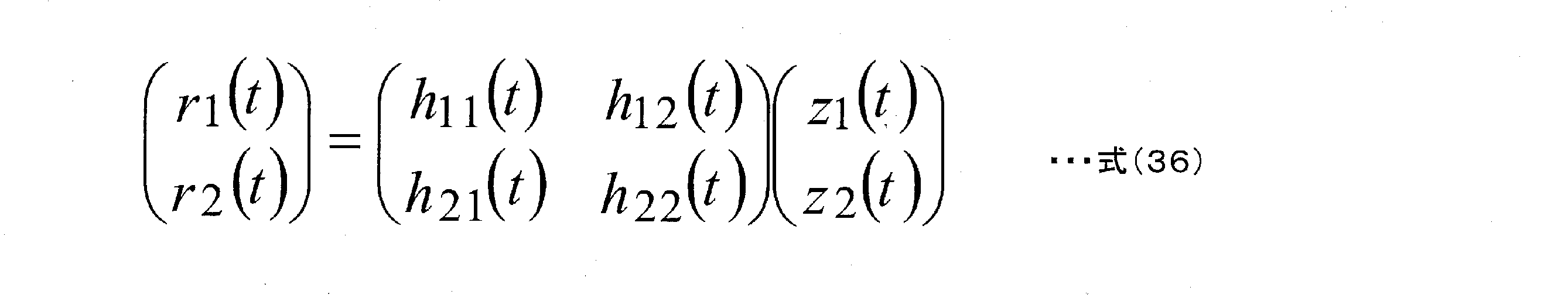
図6は、本実施の形態における重み付け方法(プリコーディング(Precoding)方法)に関連する図であり、重み付け合成部600は、図3の重み付け合成部308Aと308Bの両者を統合した重み付け合成部である。図6に示すように、ストリームs1(t)およびストリームs2(t)は、図3のベースバンド信号307Aおよび307Bに相当する、つまり、QPSK、16QAM、64QAMなどの変調方式のマッピングにしたがったベースバンド信号同相I、直交Q成分となる。そして、図6のフレーム構成のようにストリームs1(t)は、シンボル番号uの信号をs1(u)、シンボル番号u+1の信号をs1(u+1)、・・・とあらわす。同様に、ストリームs2(t)は、シンボル番号uの信号をs2(u)、シンボル番号u+1の信号をs2(u+1)、・・・とあらわす。そして、重み付け合成部600は、図3におけるベースバンド信号307A(s1(t))および307B(s2(t))、重み付け情報に関する情報315を入力とし、重み付け情報に関する情報315にしたがった重み付け方法を施し、図3の重み付け合成後の信号309A(z1(t))、309B(z2(t))を出力する。このとき、
z1(t)、z2(t)は以下のようにあらわされる。
シンボル番号4iのとき(iは0以上の整数とする):
FIG. 6 is a diagram related to the weighting method (precoding method) in the present embodiment, and the
z1 (t) and z2 (t) are represented as follows.
When the symbol number is 4i (i is an integer of 0 or more):

ただし、jは虚数単位。
シンボル番号4i+1のとき:
However, j is an imaginary unit.
When the symbol number is 4i + 1:

シンボル番号4i+2のとき: When the symbol number is 4i + 2:

シンボル番号4i+3のとき: When the symbol number is 4i + 3:

このように、図6の重み付け合成部は、4スロット周期で規則的にプリコーディングウェイトを切り替えるものとする。(ただし、ここでは、4スロットで規則的にプリコーディングウェイトを切り替える方式としているが、規則的に切り替えるスロット数は4スロットに限ったものではない。)
ところで、非特許文献4において、スロットごとにプリコーディングウェイトを切り替えることが述べられており、非特許文献4では、プリコーディングウェイトをランダムに切り替えることを特徴としている。一方で、本実施の形態では、ある周期を設け規則的にプリコーディングウェイトを切り替えることを特徴としており、また、4つのプリコーディングウェイトで構成される2行2列のプリコーディングウェイト行列において、4つのプリコーディングウェイトの各絶対値が等しく(1/sqrt(2))、この特徴をもつプリコーディングウェイト行列を規則的に切り替えることを特徴としている。
As described above, the weighted composition unit of FIG. 6 periodically switches the precoding weight in a 4-slot cycle. (However, although the method of regularly switching the precoding weight in 4 slots is used here, the number of slots that are regularly switched is not limited to 4 slots.)
By the way,
LOS環境では、特殊なプリコーディング行列を用いると、受信品質が大きく改善する可能性があるが、直接波の状況により、その特殊なプリコーディング行列は異なる。しかし、LOS環境には、ある規則があり、この規則に従い特殊なプリコーディング行列を規則的に切り替えれば、データの受信品質が大きく改善する。一方、ランダムにプリコーディング行列を切り替えた場合、先にのべた特殊なプリコーディング行列以外のプリコーディング行列も存在することになる可能性、また、LOS環境には適さない片寄ったプリコーディング行列のみでプリコーディングを行う可能性も存在し、これにより、必ずしもLOS環境で、良好な受信品質が得られるとは限らない。したがって、LOS環境に適したプリコーディング切り替え方法を実現する必要があり、本発明は、それに関するプリコーディング方法を提案している。 In the LOS environment, the use of a special precoding matrix may greatly improve the reception quality, but the special precoding matrix differs depending on the direct wave conditions. However, there is a certain rule in the LOS environment, and if a special precoding matrix is regularly switched according to this rule, the data reception quality is greatly improved. On the other hand, if the precoding matrix is switched randomly, there is a possibility that there will be precoding matrices other than the special precoding matrix mentioned above, and only the biased precoding matrix that is not suitable for the LOS environment will be used. There is also the possibility of precoding, which does not necessarily result in good reception quality in the LOS environment. Therefore, it is necessary to realize a precoding switching method suitable for the LOS environment, and the present invention proposes a precoding method related thereto.
図7は、本実施の形態における受信装置700の構成の一例を示している。無線部703_Xは、アンテナ701_Xで受信された受信信号702_Xを入力とし、周波数変換、直交復調等の処理を施し、ベースバンド信号704_Xを出力する。
送信装置で送信された変調信号z1におけるチャネル変動推定部705_1は、ベースバンド信号704_Xを入力とし、図5におけるチャネル推定用のリファレンスシンボル501_1を抽出し、式(36)のh11に相当する値を推定し、チャネル推定信号706_1を出力する。
FIG. 7 shows an example of the configuration of the receiving device 700 according to the present embodiment. The radio unit 703_X receives the received signal 702_X received by the antenna 701_X as an input, performs processing such as frequency conversion and orthogonal demodulation, and outputs the baseband signal 704_X.
The channel variation estimation unit 705_1 in the modulation signal z1 transmitted by the transmission device receives the baseband signal 704_X as an input, extracts the reference symbol 501_1 for channel estimation in FIG. 5, and obtains a value corresponding to h11 in the equation (36). Estimate and output the channel estimation signal 706_1.
送信装置で送信された変調信号z2におけるチャネル変動推定部705_2は、ベースバンド信号704_Xを入力とし、図5におけるチャネル推定用のリファレンスシンボル501_2を抽出し、式(36)のh12に相当する値を推定し、チャネル推定信号706_2を出力する。 The channel variation estimation unit 705_2 in the modulation signal z2 transmitted by the transmission device receives the baseband signal 704_X as an input, extracts the reference symbol 501_2 for channel estimation in FIG. 5, and obtains a value corresponding to h12 in the equation (36). Estimate and output the channel estimation signal 706_2.
無線部703_Yは、アンテナ701_Yで受信された受信信号702_Yを入力とし、周波数変換、直交復調等の処理を施し、ベースバンド信号704_Yを出力する。
送信装置で送信された変調信号z1におけるチャネル変動推定部707_1は、ベースバンド信号704_Yを入力とし、図5におけるチャネル推定用のリファレンスシンボル501_1を抽出し、式(36)のh21に相当する値を推定し、チャネル推定信号708_1を出力する。
The radio unit 703_Y receives the received signal 702_Y received by the antenna 701_Y as an input, performs processing such as frequency conversion and orthogonal demodulation, and outputs the baseband signal 704_Y.
The channel variation estimation unit 707_1 in the modulation signal z1 transmitted by the transmission device receives the baseband signal 704_Y as an input, extracts the reference symbol 501_1 for channel estimation in FIG. 5, and obtains a value corresponding to h21 in the equation (36). Estimate and output the channel estimation signal 708_1.
送信装置で送信された変調信号z2におけるチャネル変動推定部707_2は、ベースバンド信号704_Yを入力とし、図5におけるチャネル推定用のリファレンスシンボル501_2を抽出し、式(36)のh22に相当する値を推定し、チャネル推定信号708_2を出力する。 The channel variation estimation unit 707_2 in the modulation signal z2 transmitted by the transmission device takes the baseband signal 704_Y as an input, extracts the reference symbol 501_2 for channel estimation in FIG. 5, and obtains a value corresponding to h22 in the equation (36). Estimate and output the channel estimation signal 708_2.
制御情報復号部709は、ベースバンド信号704_Xおよび704_Yを入力とし、図5の送信方法を通知するためのシンボル500_1を検出し、送信装置が通知した送信方法の情報に関する信号710を出力する。
The control
信号処理部711は、ベースバンド信号704_X、704_Y、チャネル推定信号706_1、706_2、708_1、708_2、及び、送信装置が通知した送信方法の
情報に関する信号710を入力とし、検波、復号を行い、受信データ712_1および712_2を出力する。
The
次に、図7の信号処理部711の動作について詳しく説明する。図8は、本実施の形態における信号処理部711の構成の一例を示している。図8は、主にINNER MIMO検波部とsoft-in/soft-outデコーダ、重み付け係数生成部から構成されている。この構成における反復復号の方法については、非特許文献2、非特許文献3で詳細が述べられているが、非特許2、非特許文献3に記載されているMIMO伝送方式は空間多重MIMO伝送方式であるが、本実施の形態における伝送方式は、時間とともにプリコーディングウェイトを変更するMIMO伝送方式である点が、非特許文献2、非特許文献3と異なる点である。式(36)における(チャネル)行列をH(t)、図6におけるプリコーディングウェイト行列をW(t)(ただし、tによりプリコーディングウェイト行列は変化する。)、受信ベクトルをR(t)=(r1(t),r2(t))T、ストリームベクトルS(t)=(s1(t),s2(t))Tとすると以下の関係式が成立する。
Next, the operation of the

このとき、受信装置は、H(t)W(t)をチャネル行列と考えることで、受信ベクトルをR(t)に対して非特許文献2、非特許文献3の復号方法を適用することができる。
したがって、図8の重み付け係数生成部819は、送信装置が通知した送信方法の情報に関する信号818(図7の710に相当)を入力とし、重み付け係数の情報に関する信号820を出力する。
At this time, the receiving device can apply the decoding methods of
Therefore, the weighting coefficient generation unit 819 of FIG. 8 inputs the signal 818 (corresponding to 710 in FIG. 7) regarding the information of the transmission method notified by the transmission device, and outputs the
INNNER MIMO検波部803は、重み付け係数の情報に関する信号820を入力とし、この信号を利用して、式(41)の演算を行うことになる。そして、反復検波・復号を行うことになるがその動作について説明する。
The INNNER
図8の信号処理部では、反復復号(反復検波)を行うため図10に示すような処理方法を行う必要がある。初めに、変調信号(ストリーム)s1の1符号語(または、1フレーム)、および、変調信号(ストリーム)s2の1符号語(または、1フレーム)の復号を行う。その結果、soft-in/soft-outデコーダから、変調信号(ストリーム)s1の1符号語(または、1フレーム)、および、変調信号(ストリーム)s2の1符号語(または、1フレーム)の各ビットの対数尤度比(LLR:Log-Likelihood Ratio)が得られる。そして、そのLLRを用いて再度、検波・復号が行われる。この操作が複数回行われる(この操作を反復復号(反復検波)と呼ぶ。)。以降では、1フレームにおける特定の時間のシンボルの対数尤度比(LLR)の作成方法を中心に説明する。 In the signal processing unit of FIG. 8, it is necessary to perform the processing method as shown in FIG. 10 in order to perform iterative decoding (repeated detection). First, one codeword (or one frame) of the modulated signal (stream) s1 and one codeword (or one frame) of the modulated signal (stream) s2 are decoded. As a result, from the soft-in / soft-out decoder, one codeword (or one frame) of the modulated signal (stream) s1 and one codeword (or one frame) of the modulated signal (stream) s2 are each. The log-likelihood ratio of bits (LLR: Log-Likelihood Ratio) is obtained. Then, the detection / decoding is performed again using the LLR. This operation is performed multiple times (this operation is called iterative decoding (repeated detection)). Hereinafter, a method of creating a log-likelihood ratio (LLR) of a symbol at a specific time in one frame will be mainly described.
図8において、記憶部815は、ベースバンド信号801X(図7のベースバンド信号704_Xに相当する。)、チャネル推定信号郡802X(図7のチャネル推定信号706_1、706_2に相当する。)、ベースバンド信号801Y(図7のベースバンド信号704_Yに相当する。)、チャネル推定信号郡802Y(図7のチャネル推定信号7
08_1、708_2に相当する。)を入力とし、反復復号(反復検波)を実現するために、式(41)におけるH(t)W(t)を実行(算出)し、算出した行列を変形チャネル信号群として記憶する。そして、記憶部815は、必要なときに上記信号を、ベースバンド信号816X、変形チャネル推定信号郡817X、ベースバンド信号816Y、変形チャネル推定信号郡817Yとして出力する。
In FIG. 8, the
It corresponds to 08_1 and 708_2. ) Is used as an input, and H (t) W (t) in the equation (41) is executed (calculated) in order to realize iterative decoding (repeated detection), and the calculated matrix is stored as a modified channel signal group. Then, the
その後の動作については、初期検波の場合と反復復号(反復検波)の場合を分けて説明する。
<初期検波の場合>
INNER MIMO検波部803は、ベースバンド信号801X、チャネル推定信号郡802X、ベースバンド信号801Y、チャネル推定信号郡802Yを入力とする。ここでは、変調信号(ストリーム)s1、変調信号(ストリーム)s2の変調方式が16QAMとして説明する。
Subsequent operations will be described separately for the case of initial detection and the case of iterative decoding (repeated detection).
<In the case of initial detection>
The INNER
INNER MIMO検波部803は、まず、チャネル推定信号郡802X、チャネル推定信号郡802YからH(t)W(t)を実行し、ベースバンド信号801Xに対応する候補信号点を求める。そのときの様子を図11に示す。図11において、●(黒丸)は、IQ平面における候補信号点であり、変調方式が16QAMのため、候補信号点は256個存在する。(ただし、図11では、イメージ図を示しているため、256個の候補信号点は示していない。)ここで、変調信号s1で伝送する4ビットをb0、b1、b2、b3、変調信号s2で伝送する4ビットをb4、b5、b6、b7とすると、図11において(b0,b1,b2,b3,b4,b5,b6,b7)に対応する候補信号点が存在することになる。そして、受信信号点1101(ベースバンド信号801Xに相当する。)と候補信号点それぞれとの2乗ユークリッド距離を求める。そして、それぞれの2乗ユークリッド距離をノイズの分散σ2で除算する。したがって、(b0,b1,b2,b3,b4,b5,b6,b7)に対応する候補信号点と受信信号点2乗ユークリッド距離をノイズの分散で除算した値をEX(b0,b1,b2,b3,b4,b5,b6,b7)が求まることになる。なお、各ベースバンド信号、変調信号s1、s2は、複素信号である。
First, the INNER
同様に、チャネル推定信号郡802X、チャネル推定信号郡802YからH(t)W(t)を実行し、ベースバンド信号801Yに対応する候補信号点をもとめ、受信信号点(ベースバンド信号801Yに相当する。)との2乗ユークリッド距離を求め、この2乗ユークリッド距離をノイズの分散σ2で除算する。したがって、(b0,b1,b2,b3,b4,b5,b6,b7)に対応する候補信号点と受信信号点2乗ユークリッド距離をノイズの分散で除算した値をEY(b0,b1,b2,b3,b4,b5,b6,b7)が求まることになる。
Similarly, H (t) W (t) is executed from the channel
そして、EX(b0,b1,b2,b3,b4,b5,b6,b7)+EY(b0,b1,b2,b3,b4,b5,b6,b7)=E(b0,b1,b2,b3,b4,b5,b6,b7)を求める。 Then, EX (b0, b1, b2, b3, b4, b5, b6, b7) + EY (b0, b1, b2, b3, b4, b5, b6, b7 ) = E (b0, b1, b2, b3). , B4, b5, b6, b7).
INNER MIMO検波部803は、E(b0,b1,b2,b3,b4,b5,b6,b7)を信号804として出力する。
対数尤度算出部805Aは、信号804を入力とし、ビットb0およびb1およびb2およびb3の対数尤度(log likelihood)を算出し、対数尤度信号806Aを出力する。ただし、対数尤度の算出では、“1”のときの対数尤度および“0”のときの対数尤度が算出される。その算出方法は、式(28)、式(29)、式(30)に示した通りであり、詳細については、非特許文献2、非特許文献3に示されている。
The INNER
The log-
同様に、対数尤度算出部805Bは、信号804を入力とし、ビットb4およびb5およびb6およびb7の対数尤度を算出し、対数尤度信号806Bを出力する。
デインタリーバ(807A)は、対数尤度信号806Aを入力とし、インタリーバ(図3のインタリーバ(304A))に対応するデインタリーブを行い、デインタリーブ後の対数尤度信号808Aを出力する。
Similarly, the log-
The deinterleaver (807A) receives the log-
同様に、デインタリーバ(807B)は、対数尤度信号806Bを入力とし、インタリーバ(図3のインタリーバ(304B))に対応するデインタリーブを行い、デインタリーブ後の対数尤度信号808Bを出力する。
Similarly, the deinterleaver (807B) takes the log-
対数尤度比算出部809Aは、デインタリーブ後の対数尤度信号808Aを入力とし、図3の符号化器302Aで符号化されたビットの対数尤度比(LLR:Log-Likelihood Ratio)を算出し、対数尤度比信号810Aを出力する。
The log-likelihood
同様に、対数尤度比算出部809Bは、デインタリーブ後の対数尤度信号808Bを入力とし、図3の符号化器302Bで符号化されたビットの対数尤度比(LLR:Log-Likelihood Ratio)を算出し、対数尤度比信号810Bを出力する。
Similarly, the log-likelihood
Soft-in/soft-outデコーダ811Aは、対数尤度比信号810Aを入力とし、復号を行い、復号後の対数尤度比812Aを出力する。
同様に、Soft-in/soft-outデコーダ811Bは、対数尤度比信号810Bを入力とし、復号を行い、復号後の対数尤度比812Bを出力する。
The Soft-in / soft-
Similarly, the Soft-in / soft-
<反復復号(反復検波)の場合、反復回数k>
インタリーバ(813A)は、k-1回目のsoft-in/soft-outデコードで得られた復号後の対数尤度比812Aを入力とし、インタリーブを行い、インタリーブ後の対数尤度比814Aを出力する。このとき、インタリーブ(813A)のインタリーブのパターンは、図3のインタリーバ(304A)のインタリーブパターンと同様である。
<In the case of iterative decoding (repeated detection), the number of iterations k>
The interleaver (813A) inputs the log-
インタリーバ(813B)は、k-1回目のsoft-in/soft-outデコードで得られた復号後の対数尤度比812Bを入力とし、インタリーブを行い、インタリーブ後の対数尤度比814Bを出力する。このとき、インタリーブ(813B)のインタリーブのパターンは、図3のインタリーバ(304B)のインタリーブパターンと同様である。
The interleaver (813B) inputs the log-
INNER MIMO検波部803は、ベースバンド信号816X、変形チャネル推定信号郡817X、ベースバンド信号816Y、変形チャネル推定信号郡817Y、インタリーブ後の対数尤度比814A、インタリーブ後の対数尤度比814Bを入力とする。ここで、ベースバンド信号801X、チャネル推定信号郡802X、ベースバンド信号801Y、チャネル推定信号郡802Yではなく、ベースバンド信号816X、変形チャネル推定信号郡817X、ベースバンド信号816Y、変形チャネル推定信号郡817Yを用いているのは、反復復号のため、遅延時間が発生しているためである。
The INNER
INNER MIMO検波部803の反復復号時の動作と、初期検波時の動作の異なる点は、インタリーブ後の対数尤度比814A、インタリーブ後の対数尤度比814Bを信号処理の際に用いていることである。INNNER MIMO検波部803は、まず、初期検波のときと同様に、E(b0,b1,b2,b3,b4,b5,b6,b7)を求める。加えて、インタリーブ後の対数尤度比814A、インタリーブ後の対数尤度比914Bから、式(11)、式(32)に相当する係数を求める。そして、E(b0,b1,b
2,b3,b4,b5,b6,b7)の値をこの求めた係数を用いて補正し、その値をE’(b0,b1,b2,b3,b4,b5,b6,b7)とし、信号804として出力する。
The difference between the operation during repeated decoding of the INNER
The values of 2, b3, b4, b5, b6, b7) are corrected using this obtained coefficient, and the value is set to E'(b0, b1, b2, b3, b4, b5, b6, b7), and the signal is signaled. Output as 804.
対数尤度算出部805Aは、信号804を入力とし、ビットb0およびb1およびb2およびb3の対数尤度(log likelihood)を算出し、対数尤度信号806Aを出力する。ただし、対数尤度の算出では、“1”のときの対数尤度および“0”のときの対数尤度が算出される。その算出方法は、式(31)、式(数32)、式(33)、式(34)、式(35)に示した通りであり、非特許文献2、非特許文献3に示されている。
The log-
同様に、対数尤度算出部805Bは、信号804を入力とし、ビットb4およびb5およびb6およびb7の対数尤度を算出し、対数尤度信号806Bを出力する。デインタリーバ以降の動作は、初期検波と同様である。
Similarly, the log-
なお、図8では、反復検波を行う場合の、信号処理部の構成について示したが、反復検波は必ずしも良好な受信品質を得る上で必須の構成ではなく、反復検波のみに必要とする構成部分、インタリーバ813A、813Bを有していない構成でもよい。このとき、INNNER MIMO検波部803は、反復的な検波を行わないことになる。
Note that FIG. 8 shows the configuration of the signal processing unit when performing repeated detection, but repeated detection is not necessarily an essential configuration for obtaining good reception quality, and is a configuration portion required only for repeated detection. , The configuration may not have interleavers 813A and 813B. At this time, the INNNER
そして、本実施の形態で重要な部分は、H(t)W(t)の演算を行うことである。なお、非特許文献5等に示されているように、QR分解を用いて初期検波、反復検波を行ってもよい。
また、非特許文献11に示されているように、H(t)W(t)に基づき、MMSE(Minimum Mean Square Error)、ZF(Zero Forcing)の線形演算を行い、初期検波を行ってもよ
い。
Then, an important part in the present embodiment is to perform the calculation of H (t) W (t). As shown in
Further, as shown in
図9は、図8と異なる信号処理部の構成であり、図4の送信装置が送信した変調信号のための信号処理部である。図8と異なる点は、soft-in/soft-outデコーダの数であり、soft-in/soft-outデコーダ901は、対数尤度比信号810A、810Bを入力とし、復号を行い、復号後の対数尤度比902を出力する。分配部903は、復号後の対数尤度比902を入力とし、分配を行う。それ以外の部分については、図8と同様の動作となる。
FIG. 9 has a signal processing unit configuration different from that of FIG. 8, and is a signal processing unit for the modulated signal transmitted by the transmission device of FIG. The difference from FIG. 8 is the number of soft-in / soft-out decoders, and the soft-in / soft-
図12に、図29のときと同様の条件で、伝送方式を本実施の形態のプリコーディングウェイトを用いた送信方法としたときのBER特性を示す。図12の(A)は、反復検波を行わないMax-log-APP(非特許文献1、非特許文献2参照)(APP:a posterior probability)のBER特性、図12の(B)は、反復検波を行ったMax-log-APP(非特許文献1、非特許文献2参照)(反復回数5回)のBER特性を示している。図12と図29を比較すると、本実施の形態の送信方法を用いると、ライスファクタが大きいときのBER特性が、空間多重MIMO伝送を用いたときのBER特性より大きく改善していることがわかり、本実施の形態の方式の有効性が確認できる。
FIG. 12 shows the BER characteristics when the transmission method is the transmission method using the precoding weight of the present embodiment under the same conditions as in FIG. 29. FIG. 12 (A) shows the BER characteristics of Max-log-APP (see
以上のように、本実施の形態のように、MIMO伝送システムの送信装置が複数アンテナから複数の変調信号を送信する際、時間とともにプリコーディングウェイトを切り替えるとともに、切り替えを規則的に行うことで、直接波が支配的なLOS環境において、従来の空間多重MIMO伝送を用いるときと比べ、伝送品質が向上するという効果を得ることができる。 As described above, as in the present embodiment, when the transmitting device of the MIMO transmission system transmits a plurality of modulated signals from a plurality of antennas, the precoding weight is switched over time and the switching is performed regularly. In the LOS environment where the direct wave is dominant, the effect of improving the transmission quality can be obtained as compared with the case of using the conventional spatial multiplex MIMO transmission.
本実施の形態において、特に、受信装置の構成については、アンテナ数を限定して、動作を説明したが、アンテナ数が増えても、同様に実施することができる。つまり、受信装置におけるアンテナ数は、本実施の形態の動作、効果に影響を与えるものではない。また、本実施の形態では、特にLDPC符号を例に説明したがこれに限ったものではなく、また、復号方法についても、soft-in/soft-outデコーダとして、sum-product復号を例に限ったものではなく、他のsoft-in/soft-outの復号方法、例えば、BCJRアルゴリズム、SOVAアルゴリズム、Msx-log-MAPアルゴリズムなどがある。詳細については、非特許文献6に示されている。
In the present embodiment, in particular, regarding the configuration of the receiving device, the operation is described by limiting the number of antennas, but the same can be performed even if the number of antennas increases. That is, the number of antennas in the receiving device does not affect the operation and effect of the present embodiment. Further, in the present embodiment, the LDPC code has been described as an example, but the present invention is not limited to this, and the decoding method is also limited to sum-produce decoding as a soft-in / soft-out decoder. There are other soft-in / soft-out decoding methods such as BCJR algorithm, SOVA algorithm, and Msx-log-MAP algorithm. Details are shown in
また、本実施の形態では、シングルキャリア方式を例に説明したが、これに限ったものではなく、マルチキャリア伝送を行った場合でも同様に実施することができる。したがって、例えば、スペクトル拡散通信方式、OFDM(Orthogonal Frequency-Division Multiplexing)方式、SC-FDMA(Single Carrier Frequency Division Multiple Access)、SC-OFDM(Single Carrier Orthogonal Frequency-Division Multiplexing)方式、非特許文献7等で示されているウェーブレットOFDM方式等を用いた場合についても同様に実施することができる。また、本実施の形態では、データシンボル以外のシンボル、例えば、パイロットシンボル(プリアンブル、ユニークワード等)、制御情報の伝送用のシンボルなどが、フレームにどのように配置されていてもよい。 Further, in the present embodiment, the single carrier method has been described as an example, but the present invention is not limited to this, and the same can be performed even when multi-carrier transmission is performed. Therefore, for example, a spectrum diffusion communication method, an OFDM (Orthogonal Frequency-Division Multiplexing) method, a SC-FDMA (Single Carrier Frequentity Division Accession Multiple Access), SC-OFDM (Single Circuit) patent, SC-OFDM (Single Circuit) The same can be performed when the wavelet OFDM method or the like shown in is used. Further, in the present embodiment, symbols other than the data symbols, for example, pilot symbols (preambles, unique words, etc.), symbols for transmitting control information, and the like may be arranged in the frame.
以下では、マルチキャリア方式の一例として、OFDM方式を用いたときの例を説明する。
図13は、OFDM方式を用いたときの送信装置の構成を示している。図13において、図3と同様に動作するものについては、同一符号を付した。
Hereinafter, as an example of the multi-carrier method, an example when the OFDM method is used will be described.
FIG. 13 shows the configuration of the transmission device when the OFDM method is used. In FIG. 13, the same reference numerals are given to those operating in the same manner as in FIG.
OFDM方式関連処理部1301Aは、重み付け後の信号309Aを入力とし、OFDM方式関連の処理を施し、送信信号1302Aを出力する。同様に、OFDM方式関連処理部1301Bは、重み付け後の信号309Bを入力とし、送信信号1302Bを出力する。
The OFDM system-related
図14は、図13のOFDM方式関連処理部1301A、1301B以降の構成の一例を示しており、図13の1301Aから312Aに関連する部分が、1401Aから1410Aであり、1301Bから312Bに関連する部分が1401Bから1410Bである。
FIG. 14 shows an example of the configuration of the OFDM system related
シリアルパラレル変換部1402Aは、重み付け後の信号1401A(図13の重み付け後の信号309Aに相当する)シリアルパラレル変換を行い、パラレル信号1403Aを出力する。
The serial-
並び換え部1404Aは、パラレル信号1403Aを入力とし、並び換えを行い、並び換え後の信号1405Aを出力する。なお、並び換えについては、後で詳しく述べる。
逆高速フーリエ変換部1406Aは、並び換え後の信号1405Aを入力とし、逆高速フーリエ変換を施し、逆フーリエ変換後の信号1407Aを出力する。
The
The inverse fast
無線部1408Aは、逆フーリエ変換後の信号1407Aを入力とし、周波数変換、増幅等の処理を行い、変調信号1409Aを出力し、変調信号1409Aはアンテナ1410Aから電波として出力される。
シリアルパラレル変換部1402Bは、重み付け後の信号1401B(図13の重み付け後の信号309Bに相当する)シリアルパラレル変換を行い、パラレル信号1403Bを
出力する。
The
The serial-
並び換え部1404Bは、パラレル信号1403Bを入力とし、並び換えを行い、並び換え後の信号1405Bを出力する。なお、並び換えについては、後で詳しく述べる。
逆高速フーリエ変換部1406Bは、並び換え後の信号1405Bを入力とし、逆高速フーリエ変換を施し、逆フーリエ変換後の信号1407Bを出力する。
The
The inverse fast
無線部1408Bは、逆フーリエ変換後の信号1407Bを入力とし、周波数変換、増幅等の処理を行い、変調信号1409Bを出力し、変調信号1409Bはアンテナ1410Bから電波として出力される。
The
図3の送信装置では、マルチキャリアを用いた伝送方式でないため、図6のように、4周期となるようにプリコーディングを切り替え、プリコーディング後のシンボルを時間軸方向に配置している。図13に示すようなOFDM方式のようなマルチキャリア伝送方式を用いている場合、当然、図3のようにプリコーディング後のシンボルを時間軸方向に配置し、それを各(サブ)キャリアごとに行う方式が考えられるが、マルチキャリア伝送方式の場合、周波数軸方向、または、周波数軸・時間軸両者を用いて配置する方法が考えられる。以降では、この点について説明する。 Since the transmission device of FIG. 3 is not a transmission method using a multi-carrier, the precoding is switched so as to have four cycles as shown in FIG. 6, and the symbols after the precoding are arranged in the time axis direction. When a multi-carrier transmission method such as the OFDM method as shown in FIG. 13 is used, naturally, the precoded symbols are arranged in the time axis direction as shown in FIG. 3, and they are arranged for each (sub) carrier. In the case of the multi-carrier transmission method, a method of arranging the transmission in the frequency axis direction or using both the frequency axis and the time axis can be considered. Hereinafter, this point will be described.
図15は、横軸周波数、縦軸時間における、図14の並び替え部1401A、1401Bにおけるシンボルの並び替え方法の一例を示しており、周波数軸は、(サブ)キャリア0から(サブ)キャリア9で構成されており、変調信号z1とz2は、同一時刻(時間)に同一の周波数帯域を使用しており、図15(A)は変調信号z1のシンボルの並び替え方法、図15(B)は変調信号z2のシンボルの並び替え方法を示している。シリアルパラレル変換部1402Aが入力とする重み付け後の信号1401Aのシンボルに対し、順番に、#1、#2、#3、#4、・・・と番号をふる。このとき、図15(a)のように、シンボル#1、#2、#3、#4、・・・をキャリア0から順番に配置し、シンボル#1から#9を時刻$1に配置し、その後、シンボル#10から#19を時刻$2に配置するというように規則的に配置するものとする。
FIG. 15 shows an example of a method of rearranging symbols in the
同様に、シリアルパラレル変換部1402Bが入力とする重み付け後の信号1401Bのシンボルに対し、順番に、#1、#2、#3、#4、・・・と番号をふる。このとき、図15(b)のように、シンボル#1、#2、#3、#4、・・・をキャリア0から順番に配置し、シンボル#1から#9を時刻$1に配置し、その後、シンボル#10から#19を時刻$2に配置するというように規則的に配置するものとする。なお、変調信号z1とz2は、複素信号である。
Similarly, the symbols of the
そして、図15に示すシンボル群1501、シンボル群1502は、図6示すプリコーディングウェイト切り替え方法を用いたときの1周期分のシンボルであり、シンボル#0は図6のスロット4iのプリコーディングウェイトを用いたときのシンボルであり、シンボル#1は図6のスロット4i+1のプリコーディングウェイトを用いたときのシンボルであり、シンボル#2は図6のスロット4i+2のプリコーディングウェイトを用いたときのシンボルであり、シンボル#3は図6のスロット4i+3のプリコーディングウェイトを用いたときのシンボルである。したがって、シンボル#xにおいて、x mod 4が0のとき、シンボル#xは図6のスロット4iのプリコーディングウェイトを用いたときのシンボルであり、x mod 4が1のとき、シンボル#xは図6のスロット4i+1のプリコーディングウェイトを用いたときのシンボルであり、x mod 4が2のとき、シンボル#xは図6のスロット4i+2のプリコーディングウェイトを用いたときのシンボルであり、x mod 4が3のとき、シンボル#xは図6のスロット4i+3のプリコーディングウェイトを用いたときのシンボルである。
The
このように、OFDM方式などのマルチキャリア伝送方式を用いた場合、シングルキャリア伝送のときとは異なり、シンボルを周波数軸方向に並べることができるという特徴を持つことになる。そして、シンボルの並べ方については、図15のような並べ方に限ったものではない。他の例について、図16、図17を用いて説明する。 As described above, when a multi-carrier transmission method such as an OFDM method is used, the symbols can be arranged in the frequency axis direction, unlike the case of single-carrier transmission. The arrangement of the symbols is not limited to the arrangement as shown in FIG. Other examples will be described with reference to FIGS. 16 and 17.
図16は、図15とは異なる、横軸周波数、縦軸時間における、図14の並び替え部1401A、1401Bにおけるシンボルの並び替え方法の一例を示しており、図16(A)は変調信号z1のシンボルの並び替え方法、図16(B)は変調信号z2のシンボルの並び替え方法を示している。図16(A)(B)が図15と異なる点は、変調信号z1のシンボルの並び替え方法と変調信号z2のシンボルの並び替え方法が異なる点であり、図16(B)では、シンボル#0から#5をキャリア4からキャリア9に配置し、シンボル#6から#9をキャリア0から3に配置し、その後、同様の規則で、シンボル#10から#19を各キャリアに配置する。このとき、図15と同様に、図16に示すシンボル群1601、シンボル群1602は、図6示すプリコーディングウェイト切り替え方法を用いたときの1周期分のシンボルである。
FIG. 16 shows an example of a symbol rearrangement method in the
図17は、図15と異なる、横軸周波数、縦軸時間における、図14の並び替え部1401A、1401Bにおけるシンボルの並び替え方法の一例を示しており、図17(A)は変調信号z1のシンボルの並び替え方法、図17(B)は変調信号z2のシンボルの並び替え方法を示している。図17(A)(B)が図15と異なる点は、図15では、シンボルをキャリアに順々に配置しているのに対し、図17では、シンボルをキャリアに順々に配置していない点である。当然であるが、図17において、図16と同様に、変調信号z1のシンボルの並び替え方法と変調信号z2の並び替え方法を異なるようにしてもよい。
FIG. 17 shows an example of a symbol rearrangement method in the
図18、図15~17とは異なる、横軸周波数、縦軸時間における、図14の並び替え部1401A、1401Bにおけるシンボルの並び替え方法の一例を示しており、図18(A)は変調信号z1のシンボルの並び替え方法、図18(B)は変調信号z2のシンボルの並び替え方法を示している。図15~17では、シンボルを周波数軸方向に並べているが、図18ではシンボルを周波数、時間軸の両者を利用して配置している。
18 (A) shows an example of the symbol rearrangement method in the
図6では、プリコーディングウェイトの切り替えを4スロットで切り替える場合の例を説明したが、ここでは、8スロットで切り替える場合を例に説明する。図18に示すシンボル群1801、シンボル群1802は、プリコーディングウェイト切り替え方法を用いたときの1周期分のシンボル(したがって、8シンボル)であり、 シンボル#0はスロット8iのプリコーディングウェイトを用いたときのシンボルであり、シンボル#1はスロット8i+1のプリコーディングウェイトを用いたときのシンボルであり、シンボル#2はスロット8i+2のプリコーディングウェイトを用いたときのシンボルであり、シンボル#3はスロット8i+3のプリコーディングウェイトを用いたときのシンボルであり、シンボル#4はスロット8i+4のプリコーディングウェイトを用いたときのシンボルであり、シンボル#5はスロット8i+5のプリコーディングウェイトを用いたときのシンボルであり、シンボル#6はスロット8i+6のプリコーディングウェイトを用いたときのシンボルであり、シンボル#7はスロット8i+7のプリコーディングウェイトを用いたときのシンボルである。したがって、シンボル#xにおいて、x mod 8が0のとき、シンボル#xはスロット8iのプリコーディングウェイトを用いたときのシンボルであり、x mod 8が1のとき、シンボル#xはスロット8i+1のプリコーディングウェイトを用いたときのシンボルであり、x mod 8が2のとき、シンボル#xはスロット8i+2のプリコーディングウェイトを用いたときのシンボルであり、x mod 8が3のとき、シンボル#xはスロット8i+3のプリコーディングウェイトを用い
たときのシンボルであり、x mod 8が4のとき、シンボル#xはスロット8i+4のプリコーディングウェイトを用いたときのシンボルであり、x mod 8が5のとき、シンボル#xはスロット8i+5のプリコーディングウェイトを用いたときのシンボルであり、x mod 8が6のとき、シンボル#xはスロット8i+6のプリコーディングウェイトを用いたときのシンボルであり、x mod 8が7のとき、シンボル#xはスロット8i+7のプリコーディングウェイトを用いたときのシンボルである。図18のシンボルの並べ方では、時間軸方向に4スロット、周波数軸方向で2スロットの計4×2=8スロットを用いて、1周期分のシンボルを配置しているが、このとき、1周期分のシンボルの数をm×nシンボル(つまり、プリコーディングウェイトはm×n種類存在する。)1周期分のシンボルを配置するのに使用する周波数軸方向のスロット(キャリア数)をn、時間軸方向に使用するスロットをmとすると、m>nとするとよい。これは、直接波の位相は、時間軸方向の変動は、周波数軸方向の変動と比較し、緩やかである。したがって、定常的な直接波の影響を小さくするために本実施の形態のプリコーディングウェイト変更を行うので、プリコーディングウェイトの変更を行う周期では直接波の変動を小さくしたい。したがって、m>nとするとよい。また、以上の点を考慮すると、周波数軸方向のみ、または、時間軸方向のみにシンボルを並び替えるより、図18のように周波数軸と時間軸の両者を用いて並び換えを行うほうが、直接波は定常的になる可能性が高く、本発明の効果を得やすいという効果が得られる。ただし、周波数軸方向に並べると、周波数軸の変動が急峻であるため、ダイバーシチゲインを得ることが出来る可能性があるので、必ずしも周波数軸と時間軸の両者を用いて並び換えを行う方法が最適な方法であるとは限らない。
In FIG. 6, an example of switching the precoding weight in 4 slots has been described, but here, a case of switching in 8 slots will be described as an example. The
図19は、図18とは異なる、横軸周波数、縦軸時間における、図14の並び替え部1401A、1401Bにおけるシンボルの並び替え方法の一例を示しており、図19(A)は変調信号z1のシンボルの並び替え方法、図19(B)は変調信号z2のシンボルの並び替え方法を示している。図19は、図18と同様、シンボルを周波数、時間軸の両者を利用して配置しているが、図18と異なる点は、図18では、周波数方向を優先し、その後、時間軸方向にシンボルを配置しているのに対し、図19では、時間軸方向を優先し、その後、時間軸方向にシンボルを配置している点である。図19において、シンボル群1901、シンボル群1902は、プリコーディング切り替え方法を用いたときの1周期分のシンボルである。
FIG. 19 shows an example of a symbol rearrangement method in the
なお、図18、図19では、図16と同様に、変調信号z1のシンボルの配置方法と変調信号z2のシンボル配置方法が異なるように配置しても同様に実施することができ、また、高い受信品質を得ることができるという効果を得ることができる。また、図18、図19において、図17のようにシンボルを順々に配置していなくても、同様に実施することができ、また、高い受信品質を得ることができるという効果を得ることができる。 It should be noted that, in FIGS. 18 and 19, similarly to FIG. 16, even if the symbol arrangement method of the modulation signal z1 and the symbol arrangement method of the modulation signal z2 are arranged differently, the same can be carried out, and it is expensive. The effect of being able to obtain reception quality can be obtained. Further, in FIGS. 18 and 19, even if the symbols are not arranged in order as in FIG. 17, the same can be performed, and the effect that high reception quality can be obtained can be obtained. can.
図27は、上記とは異なる、横軸周波数、縦軸時間における図14の並び替え部1401A、140Bにおけるシンボルの並び換え方法の一例を示している。式(37)~式(40)のような4スロットを用いて規則的にプリコーディング行列を切り替える場合を考える。図27において特徴的な点は、周波数軸方向にシンボルを順に並べているが、時間軸方向に進めた場合、サイクリックにn(図27の例ではn=1)シンボルサイクリックシフトさせている点である。図27における周波数軸方向のシンボル群2710に示した4シンボルにおいて、式(37)~式(40)のプリコーディング行列の切り替えを行うものとする。
FIG. 27 shows an example of a symbol rearrangement method in the
このとき、#0のシンボルでは式(37)のプリコーディング行列を用いたプリコーディング、#1では式(38)のプリコーディング行列を用いたプリコーディング、#2では式(39)のプリコーディング行列を用いたプリコーディング、#3では式(40)の
プリコーディング行列を用いたプリコーディングを行うものとする。
At this time, the symbol of # 0 is precoding using the precoding matrix of equation (37), # 1 is precoding using the precoding matrix of equation (38), and # 2 is the precoding matrix of equation (39). Precoding using the precoding matrix of Eq. (40) is performed in # 3.
周波数軸方向のシンボル群2720についても同様に、#4のシンボルでは式(37)のプリコーディング行列を用いたプリコーディング、#5では式(38)のプリコーディング行列を用いたプリコーディング、#6では式(39)のプリコーディング行列を用いたプリコーディング、#7では式(40)のプリコーディング行列を用いたプリコーディングを行うものとする。
Similarly, for the
時間$1のシンボルにおいて、上記のようなプリコーディング行列の切り替えを行ったが、時間軸方向において、サイクリックシフトしているため、シンボル群2701、2702、2703、2704については以下のようにプリコーディング行列の切り替えを行うことになる。
The precoding matrix was switched as described above for the symbol of time $ 1, but since it is cyclically shifted in the time axis direction, the
時間軸方向のシンボル群2701では、#0のシンボルでは式(37)のプリコーディング行列を用いたプリコーディング、#9では式(38)のプリコーディング行列を用いたプリコーディング、#18では式(39)のプリコーディング行列を用いたプリコーディング、#27では式(40)のプリコーディング行列を用いたプリコーディングを行うものとする。
In the
時間軸方向のシンボル群2702では、#28のシンボルでは式(37)のプリコーディング行列を用いたプリコーディング、#1では式(38)のプリコーディング行列を用いたプリコーディング、#10では式(39)のプリコーディング行列を用いたプリコーディング、#19では式(40)のプリコーディング行列を用いたプリコーディングを行うものとする。
In the
時間軸方向のシンボル群2703では、#20のシンボルでは式(37)のプリコーディング行列を用いたプリコーディング、#29では式(38)のプリコーディング行列を用いたプリコーディング、#1では式(39)のプリコーディング行列を用いたプリコーディング、#10では式(40)のプリコーディング行列を用いたプリコーディングを行うものとする。
In the
時間軸方向のシンボル群2704では、#12のシンボルでは式(37)のプリコーディング行列を用いたプリコーディング、#21では式(38)のプリコーディング行列を用いたプリコーディング、#30では式(39)のプリコーディング行列を用いたプリコーディング、#3では式(40)のプリコーディング行列を用いたプリコーディングを行うものとする。
In the
図27においての特徴は、例えば#11のシンボルに着目した場合、同一時刻の周波数軸方向の両隣のシンボル(#10と#12)は、ともに#11とは異なるプリコーディング行列を用いてプリコーディングを行っているとともに、#11のシンボルの同一キャリアの時間軸方向の両隣のシンボル(#2と#20)は、ともに#11とは異なるプリコーディング行列を用いてプリコーディングを行っていることである。そして、これは#11のシンボルに限ったものではなく、周波数軸方向および時間軸方向ともに両隣にシンボルが存在するシンボルすべてにおいて#11のシンボルと同様の特徴をもつことになる。これにより、効果的にプリコーディング行列を切り替えていることになり、直接波の定常的な状況に対する影響を受けづらくなるため、データの受信品質が改善される可能性が高くなる。 The feature in FIG. 27 is that, for example, when focusing on the symbol of # 11, the symbols (# 10 and # 12) on both sides in the frequency axis direction at the same time are precoded using a precoding matrix different from that of # 11. And the symbols (# 2 and # 20) on both sides of the same carrier of the symbol of # 11 in the time axis direction are precoded using a precoding matrix different from that of # 11. be. And this is not limited to the symbol of # 11, and all the symbols having symbols on both sides in the frequency axis direction and the time axis direction have the same characteristics as the symbol of # 11. As a result, the precoding matrix is effectively switched, and it is less likely to be affected by the constant condition of the direct wave, so that the data reception quality is likely to be improved.
図27では、n=1として説明したが、これに限ったものではなく、n=3としても同様に実施することができる。また、図27では、周波数軸にシンボルを並べ、時間が軸方
向にすすむ場合、シンボルの配置の順番をサイクリックシフトするという特徴を持たせることで、上記の特徴を実現したが、シンボルをランダム(規則的であってもよい)に配置することで上記特徴を実現するような方法もある。
In FIG. 27, the description is made with n = 1, but the present invention is not limited to this, and the same can be performed with n = 3. Further, in FIG. 27, the above characteristics are realized by arranging the symbols on the frequency axis and cyclically shifting the order of the arrangement of the symbols when the time advances in the axial direction, but the symbols are random. There is also a method of realizing the above-mentioned characteristics by arranging them (which may be regular).
(実施の形態2)
実施の形態1では、図6に示すようなプリコーディングウェイトを規則的に切り替える場合について説明したが、本実施の形態では、図6のプリコーディングウェイトとは異なる具体的なプリコーディングウェイトの設計方法について説明する。
(Embodiment 2)
In the first embodiment, a case where the precoding weights as shown in FIG. 6 are regularly switched has been described, but in the present embodiment, a specific precoding weight design method different from the precoding weights in FIG. 6 has been described. Will be explained.
図6では、式(37)~式(40)のプリコーディングウェイトを切り替える方法を説明した。これを一般化した場合、プリコーディングウェイトは以下のように変更することができる。(ただし、プリコーディングウェイトの切り替え周期は4とし、式(37)~式(40)と同様の記載を行う。)
シンボル番号4iのとき(iは0以上の整数とする):
In FIG. 6, a method of switching the precoding weights of the equations (37) to (40) has been described. If this is generalized, the precoding weight can be changed as follows. (However, the switching cycle of the precoding weight is set to 4, and the same description as in equations (37) to (40) is used.)
When the symbol number is 4i (i is an integer of 0 or more):

ただし、jは虚数単位。
シンボル番号4i+1のとき:
However, j is an imaginary unit.
When the symbol number is 4i + 1:

シンボル番号4i+2のとき: When the symbol number is 4i + 2:

シンボル番号4i+3のとき: When the symbol number is 4i + 3:

そして、式(36)および式(41)から、受信ベクトルをR(t)=(r1(t),r2(t))Tを以下のようにあらわすことができる。
シンボル番号4iのとき:
Then, from the equation (36) and the equation (41), the reception vector can be expressed as R (t) = (r1 (t), r2 (t)) T as follows.
When the symbol number is 4i:

シンボル番号4i+1のとき: When the symbol number is 4i + 1:

シンボル番号4i+2のとき: When the symbol number is 4i + 2:

シンボル番号4i+3のとき: When the symbol number is 4i + 3:

このとき、チャネル要素h11(t)、h12(t)、h21(t)、h22(t)において、直接波の成分しか存在しないと仮定し、その直接波の成分の振幅成分は全て等し
く、また、時間において、変動が起こらないとする。すると、式(46)~式(49)は以下のようにあらわすことができる。
シンボル番号4iのとき:
At this time, it is assumed that only the direct wave component exists in the channel elements h 11 (t), h 12 (t), h 21 (t), and h 22 (t), and the amplitude component of the direct wave component is It is assumed that they are all equal and that there is no fluctuation over time. Then, the equations (46) to (49) can be expressed as follows.
When the symbol number is 4i:

シンボル番号4i+1のとき: When the symbol number is 4i + 1:

シンボル番号4i+2のとき: When the symbol number is 4i + 2:

シンボル番号4i+3のとき: When the symbol number is 4i + 3:

ただし、式(50)~式(53)において、Aは正の実数であり、qは複素数であるものとする。このA及びqの値は、送信装置と受信装置との位置関係に応じて決まる。そして、式(50)~式(53)を以下のようにあらわすものとする。
シンボル番号4iのとき:
However, in equations (50) to (53), it is assumed that A is a positive real number and q is a complex number. The values of A and q are determined according to the positional relationship between the transmitting device and the receiving device. Then, equations (50) to (53) are expressed as follows.
When the symbol number is 4i:

シンボル番号4i+1のとき: When the symbol number is 4i + 1:

シンボル番号4i+2のとき: When the symbol number is 4i + 2:

シンボル番号4i+3のとき: When the symbol number is 4i + 3:

すると、qが以下のようにあらわされるとき、r1、r2に、s1またはs2のいずれか一方に基づく信号成分が含まれなくなるため、s1、s2のいずれかの信号を得ることができなくなる。
シンボル番号4iのとき:
Then, when q is expressed as follows, since the signal component based on either s1 or s2 is not included in r1 and r2, the signal of either s1 or s2 cannot be obtained.
When the symbol number is 4i:

シンボル番号4i+1のとき: When the symbol number is 4i + 1:

シンボル番号4i+2のとき: When the symbol number is 4i + 2:

シンボル番号4i+3のとき: When the symbol number is 4i + 3:
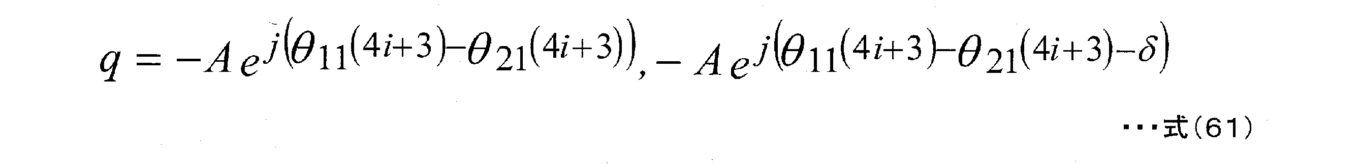
このとき、シンボル番号4i、4i+1、4i+2、4i+3において、qが同一の解をもつと、直接波のチャネル要素は大きな変動がないため、qの値が上記の同一解と等しいチャネル要素を有する受信装置は、いずれのシンボル番号においても、良好な受信品質を得ることができなくなるため、誤り訂正符号を導入しても、誤り訂正能力を得ることが難しい。したがって、qが同一の解をもたないためには、qの2つの解のうち、δを含まない方の解に着目すると、式(58)~式(61)から、以下の条件が必要となる。
At this time, if q has the same solution in the

(xは0,1,2,3であり、yは0,1,2,3であり、x≠yである。)
条件#1を満たす例として、
(例#1)
<1> θ11(4i)=θ11(4i+1)=θ11(4i+2)=θ11(4i+3)=0ラジアン
とし、
<2> θ21(4i)=0ラジアン
<3> θ21(4i+1)=π/2ラジアン
<4> θ21(4i+2)=πラジアン
<5> θ21(4i+3)=3π/2ラジアン
と設定する方法が考えられる。(上記は例であり、(θ21(4i),θ21(4i+1),θ21(4i+2),θ21(4i+3))のセットには、0ラジアン、π/2ラジアン、πラジアン、3π/2ラジアンが一つずつ存在すればよい。)このとき、特に、<1>の条件があると、ベースバンド信号S1(t)に対し、信号処理(回転処理)を与える必要がないため、回路規模の削減を図ることができるという利点がある。別の例として、
(例#2)
<6> θ11(4i)=0ラジアン
<7> θ11(4i+1)=π/2ラジアン
<8> θ11(4i+2)=πラジアン
<9> θ11(4i+3)=3π/2ラジアン
とし、
<10> θ21(4i)=θ21(4i+1)=θ21(4i+2)=θ21(4i+3)=0 ラジアン
と設定する方法も考えられる。(上記は例であり、(θ11(4i),θ11(4i+1),θ11(4i+2),θ11(4i+3))のセットには、0ラジアン、π/2ラジアン、πラジアン、3π/2ラジアンが一つずつ存在すればよい。)このとき、特に、<6>の条件があると、ベースバンド信号S2(t)に対し、信号処理(回転処理)を与える必要がないため、回路規模の削減を図ることができるという利点がある。さらに別の例として、以下をあげる。
(例#3)
<11> θ11(4i)=θ11(4i+1)=θ11(4i+2)=θ11(4i+3)=0 ラジアン
とし、
<12> θ21(4i)=0ラジアン
<13> θ21(4i+1)=π/4ラジアン
<14> θ21(4i+2)=π/2ラジアン
<15> θ21(4i+3)=3π/4ラジアン
(上記は例であり、(θ21(4i),θ21(4i+1),θ21(4i+2),θ21(4i+3))のセットには、0ラジアン、π/4ラジアン、π/2ラジアン、3π/4ラジアンが一つずつ存在すればよい。)
(例#4)
<16> θ11(4i)=0ラジアン
<17> θ11(4i+1)=π/4ラジアン
<18> θ11(4i+2)=π/2ラジアン
<19> θ11(4i+3)=3π/4ラジアン
とし、
<20> θ21(4i)=θ21(4i+1)=θ21(4i+2)=θ21(4i+3)=0 ラジアン
(上記は例であり、(θ11(4i),θ11(4i+1),θ11(4i+2),θ11(4i+3))のセットには、0ラジアン、π/4ラジアン、π/2ラジアン、3π/4ラジアンが一つずつ存在すればよい。)
なお、4つの例をあげたが、条件#1を満たす方法はこれに限ったものではない。
(X is 0,1,2,3, y is 0,1,2,3, and x ≠ y.)
As an example of
(Example # 1)
<1> θ11 (4i) = θ11 (4i + 1) = θ11 (4i + 2) = θ11 (4i + 3) = 0 radians.
<2> θ21 (4i) = 0 radians <3> θ21 (4i + 1) = π / 2 radians <4> θ21 (4i + 2) = π radians <5> θ21 (4i + 3) = 3π / 2 radians Be done. (The above is an example, and in the set of (θ21 (4i), θ21 (4i + 1), θ21 (4i + 2), θ21 (4i + 3)), 0 radian, π / 2 radian, π radian, and 3π / 2 radian are one. At this time, in particular, if the condition <1> is satisfied, it is not necessary to give signal processing (rotation processing) to the baseband signal S1 (t), so that the circuit scale can be reduced. It has the advantage of being able to be planned. As another example
(Example # 2)
<6> θ11 (4i) = 0 radians <7> θ11 (4i + 1) = π / 2 radians <8> θ11 (4i + 2) = π radians <9> θ11 (4i + 3) = 3π / 2 radians.
<10> A method of setting θ21 (4i) = θ21 (4i + 1) = θ21 (4i + 2) = θ21 (4i + 3) = 0 radians is also conceivable. (The above is an example, and in the set of (θ11 (4i), θ11 (4i + 1), θ11 (4i + 2), θ11 (4i + 3)), 0 radian, π / 2 radian, π radian, and 3π / 2 radian are one. At this time, in particular, if the condition <6> is satisfied, it is not necessary to give signal processing (rotation processing) to the baseband signal S2 (t), so that the circuit scale can be reduced. It has the advantage of being able to be planned. As yet another example, the following is given.
(Example # 3)
<11> θ11 (4i) = θ11 (4i + 1) = θ11 (4i + 2) = θ11 (4i + 3) = 0 radians.
<12> θ21 (4i) = 0 radians <13> θ21 (4i + 1) = π / 4 radians <14> θ21 (4i + 2) = π / 2 radians <15> θ21 (4i + 3) = 3π / 4 radians (the above is an example) In the set of (θ21 (4i), θ21 (4i + 1), θ21 (4i + 2), θ21 (4i + 3)), there are 0 radians, π / 4 radians, π / 2 radians, and 3π / 4 radians one by one. It should exist.)
(Example # 4)
<16> θ11 (4i) = 0 radians <17> θ11 (4i + 1) = π / 4 radians <18> θ11 (4i + 2) = π / 2 radians <19> θ11 (4i + 3) = 3π / 4 radians.
<20> θ21 (4i) = θ21 (4i + 1) = θ21 (4i + 2) = θ21 (4i + 3) = 0 radians (The above is an example, and (θ11 (4i), θ11 (4i + 1), θ11 (4i + 2), θ11 ( There may be one 0 radian, one π / 4 radian, one π / 2 radian, and one 3π / 4 radian in the set of 4i + 3)).)
Although four examples have been given, the method of
次に、θ11、θ12のみだけではなく、λ、δについての設計要件について説明する。λについ、ある値に設定すればよく、要件としては、δについての要件を与える必要がある。そこで、λを0ラジアンとした場合のδの設定方法について説明する。 Next, not only θ11 and θ12 but also design requirements for λ and δ will be described. It suffices to set a certain value for λ, and it is necessary to give a requirement for δ as a requirement. Therefore, a method of setting δ when λ is set to 0 radians will be described.
この場合、δに対し、π/2ラジアン≦|δ|≦πラジアン、とすると、特に、LOS
環境において、良好な受信品質を得ることができる。
ところで、シンボル番号4i、4i+1、4i+2、4i+3において、それぞれ、悪い受信品質となるqは2点存在する。したがって、2×4=8点の点が存在することになる。LOS環境において、特定の受信端末において受信品質が劣化することを防ぐためには、これら8点がすべて異なる解であるとよい。この場合、<条件#1>に加え、<条件#2>の条件が必要となる。
In this case, if π / 2 radians ≤ | δ | ≤ π radians with respect to δ, in particular, LOS
Good reception quality can be obtained in the environment.
By the way, in the

加えて、これら8点の位相が均一に存在するとよい。(直接波の位相は、一様分布となる可能性が高いと考えられるので)以下では、この要件を満たすδの設定方法について説明する。 In addition, it is preferable that the phases of these eight points exist uniformly. (Since the phase of the direct wave is likely to have a uniform distribution), the setting method of δ that satisfies this requirement will be described below.
(例#1)(例#2)の場合、δを±3π/4ラジアンと設定することで、受信品質の悪い点を、位相が均一に存在するようになる。例えば、(例#1)とし、δを3π/4ラジアンとすると、(Aは正の実数とする)図20のように、4スロットに1回受信品質が悪くなる点が存在する。(例#3)(例#4)の場合、δを±πラジアンと設定することで、受信品質の悪い点を、位相が均一に存在するようになる。例えば、(例#3)とし、δをπラジアンとすると図21のように、4スロットに1回受信品質が悪くなる点が存在する。(チャネル行列Hにおける要素qが、図20、図21に示す点に存在すると、受信品質が劣化することになる。)
以上のようにすることで、LOS環境において、良好な受信品質を得ることができる。上記では、4スロット周期で、プリコーディングウェイトを変更する例で説明したが、以下では、Nスロット周期で、プリコーディングウェイトを変更する場合について説明する。実施の形態1、および、上述の説明と同様に考えると、シンボル番後に対し、以下であらわされるような処理を行うことになる。
シンボル番号Niのとき(iは0以上の整数とする):
In the case of (Example # 1) and (Example # 2), by setting δ to ± 3π / 4 radians, the poor reception quality is uniformly present in phase. For example, assuming (Example # 1) and δ being 3π / 4 radians, there is a point that the reception quality deteriorates once in 4 slots as shown in FIG. 20 (A is a positive real number). In the case of (Example # 3) (Example # 4), by setting δ to ± π radian, the phase of poor reception quality can be uniformly present. For example, if (Example # 3) is set and δ is π radian, there is a point that the reception quality deteriorates once in 4 slots as shown in FIG. (If the element q in the channel matrix H exists at the points shown in FIGS. 20 and 21, the reception quality deteriorates.)
By doing the above, good reception quality can be obtained in the LOS environment. In the above, an example of changing the precoding weight in a 4-slot cycle has been described, but in the following, a case where the precoding weight is changed in an N-slot cycle will be described. Considering the same as that of the first embodiment and the above description, the processing as shown below is performed for the symbol number.
When the symbol number Ni (i is an integer of 0 or more):

ただし、jは虚数単位。
シンボル番号Ni+1のとき:
However, j is an imaginary unit.
When the symbol number is Ni + 1:

・
・
・
シンボル番号Ni+k(k=0、1、・・・、N-1)のとき:
・
・
・
When the symbol number Ni + k (k = 0, 1, ..., N-1):

・
・
・
シンボル番号Ni+N-1のとき:
・
・
・
When the symbol number is Ni + N-1:
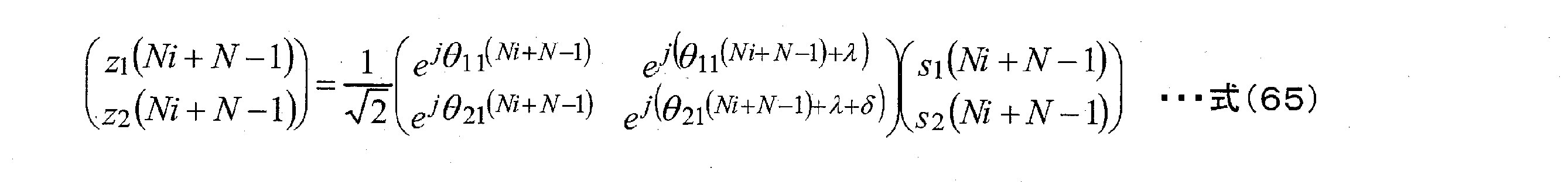
よって、r1、r2は以下のようにあらわされる。
シンボル番号Niのとき(iは0以上の整数とする):
Therefore, r1 and r2 are represented as follows.
When the symbol number Ni (i is an integer of 0 or more):

ただし、jは虚数単位。
シンボル番号Ni+1のとき:
However, j is an imaginary unit.
When the symbol number is Ni + 1:

・
・
・
シンボル番号Ni+k(k=0、1、・・・、N-1)のとき:
・
・
・
When the symbol number Ni + k (k = 0, 1, ..., N-1):

・
・
・
シンボル番号Ni+N-1のとき:
・
・
・
When the symbol number is Ni + N-1:
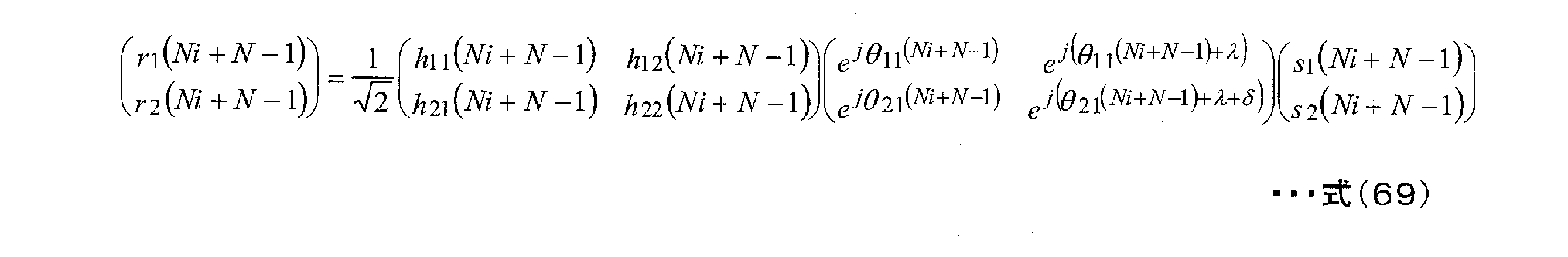
このとき、チャネル要素h11(t)、h12(t)、h21(t)、h22(t)において、直接波の成分しか存在しないと仮定し、その直接波の成分の振幅成分は全て等しく、また、時間において、変動が起こらないとする。すると、式(66)~式(69)は以下のようにあらわすことができる。
シンボル番号Niのとき(iは0以上の整数とする):
At this time, it is assumed that only the direct wave component exists in the channel elements h 11 (t), h 12 (t), h 21 (t), and h 22 (t), and the amplitude component of the direct wave component is It is assumed that they are all equal and that there is no fluctuation over time. Then, equations (66) to (69) can be expressed as follows.
When the symbol number Ni (i is an integer of 0 or more):

ただし、jは虚数単位。
シンボル番号Ni+1のとき:
However, j is an imaginary unit.
When the symbol number is Ni + 1:

・
・
・
シンボル番号Ni+k(k=0、1、・・・、N-1)のとき:
・
・
・
When the symbol number Ni + k (k = 0, 1, ..., N-1):

・
・
・
シンボル番号Ni+N-1のとき:
・
・
・
When the symbol number is Ni + N-1:

ただし、式(70)~式(73)において、Aは実数であり、qは複素数であるものとする。このA及びqの値は、送信装置と受信装置との位置関係に応じて決まる。そして、式(70)~式(73)を以下のようにあらわすものとする。
シンボル番号Niのとき(iは0以上の整数とする):
However, in equations (70) to (73), it is assumed that A is a real number and q is a complex number. The values of A and q are determined according to the positional relationship between the transmitting device and the receiving device. Then, equations (70) to (73) are expressed as follows.
When the symbol number Ni (i is an integer of 0 or more):

ただし、jは虚数単位。
シンボル番号Ni+1のとき:
However, j is an imaginary unit.
When the symbol number is Ni + 1:

・
・
・
シンボル番号Ni+k(k=0、1、・・・、N-1)のとき:
・
・
・
When the symbol number Ni + k (k = 0, 1, ..., N-1):

・
・
・
シンボル番号Ni+N-1のとき:
・
・
・
When the symbol number is Ni + N-1:
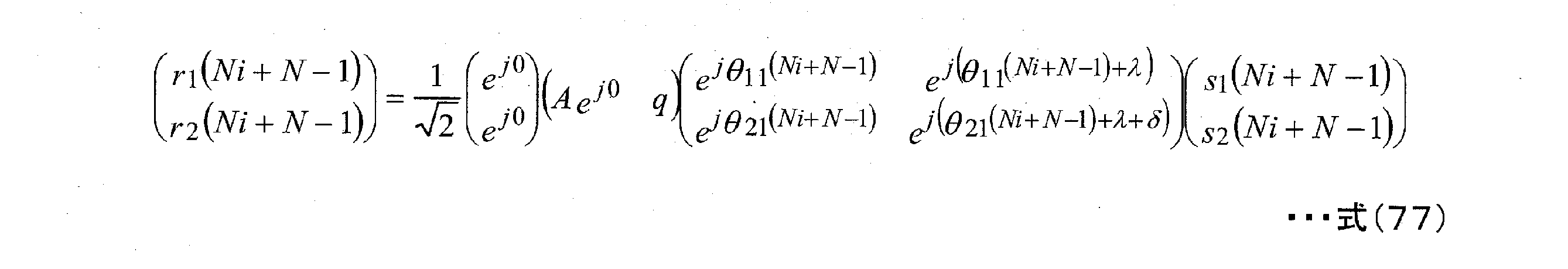
すると、qが以下のようにあらわされるとき、r1、r2に、s1またはs2のいずれか一方に基づく信号成分が含まれなくなるため、s1、s2のいずれかの信号を得ることができなくなる。
シンボル番号Niのとき(iは0以上の整数とする):
Then, when q is expressed as follows, since the signal component based on either s1 or s2 is not included in r1 and r2, the signal of either s1 or s2 cannot be obtained.
When the symbol number Ni (i is an integer of 0 or more):

シンボル番号Ni+1のとき: When the symbol number is Ni + 1:

・
・
・
シンボル番号Ni+k(k=0、1、・・・、N-1)のとき:
・
・
・
When the symbol number Ni + k (k = 0, 1, ..., N-1):

・
・
・
シンボル番号Ni+N-1のとき:
・
・
・
When the symbol number is Ni + N-1:

このとき、シンボル番号N~Ni+N-1において、qが同一の解をもつと、直接波のチャネル要素は大きな変動がないため、qの値が上記の同一解と等しい受信装置は、いずれのシンボル番号においても、良好な受信品質を得ることができなくなるため、誤り訂正符号を導入しても、誤り訂正能力を得ることが難しい。したがって、qが同一の解をもたないためには、qの2つの解のうち、δを含まないほうの解に着目すると、式(78)~式(81)から、以下の条件が必要となる。 At this time, if q has the same solution in the symbol numbers N to Ni + N-1, the channel element of the direct wave does not have a large fluctuation. Therefore, the receiving device having the same value of q as the above symbol has any symbol. Even with numbers, it is not possible to obtain good reception quality, so it is difficult to obtain error correction capability even if an error correction code is introduced. Therefore, in order for q not to have the same solution, focusing on the solution that does not include δ among the two solutions of q, the following conditions are required from equations (78) to (81). Will be.

(xは0,1,2,・・・,N-2,N-1であり、yは0,1,2,・・・,N-2,N-1であり、x≠yである。)
次に、θ11、θ12のみだけではなく、λ、δについての設計要件について説明する。λについ、ある値に設定すればよく、要件としては、δについての要件を与える必要がある。そこで、λを0ラジアンとした場合のδの設定方法について説明する。
(X is 0,1,2, ..., N-2, N-1, y is 0,1,2, ..., N-2, N-1, and x ≠ y. .)
Next, not only θ11 and θ12 but also design requirements for λ and δ will be described. It suffices to set a certain value for λ, and it is necessary to give a requirement for δ as a requirement. Therefore, a method of setting δ when λ is set to 0 radians will be described.
この場合、4スロット周期でプリコーディングウェイトを変更する方法のときと同様に、δに対し、π/2ラジアン≦|δ|≦πラジアン、とすると、特に、LOS環境において、良好な受信品質を得ることができる。 In this case, as in the case of the method of changing the precoding weight in a 4-slot cycle, if π / 2 radians ≤ | δ | ≤ π radians for δ, good reception quality is obtained especially in the LOS environment. Obtainable.
シンボル番号Ni~Ni+N-1において、それぞれ、悪い受信品質となるqは2点存在する、したがって、2N点の点が存在することになる。LOS環境において、良好な特性を得るためには、これら2N点がすべて異なる解であるとよい。この場合、<条件#3>に加え、<条件#4>の条件が必要となる。
In the symbol numbers Ni to Ni + N-1, there are two points of q having poor reception quality, and therefore there are two points of points. In order to obtain good characteristics in the LOS environment, it is preferable that these 2N points are all different solutions. In this case, the condition of <

加えて、これら2N点の位相が均一に存在するとよい。(各受信装置における直接波の位相は、一様分布となる可能性が高いと考えられるので)
以上のように、MIMO伝送システムの送信装置が複数アンテナから複数の変調信号を送信する際、時間とともにプリコーディングウェイトを切り替えるとともに、切り替えを規則的に行うことで、直接波が支配的なLOS環境において、従来の空間多重MIMO伝送を用いるときと比べ、伝送品質が向上するという効果を得ることができる。
In addition, it is preferable that the phases of these 2N points exist uniformly. (Because the phase of the direct wave in each receiving device is likely to be uniformly distributed)
As described above, when the transmitter of the MIMO transmission system transmits a plurality of modulated signals from a plurality of antennas, the precoding weight is switched over time and the switching is performed regularly, so that the LOS environment in which the direct wave is dominant is dominated. In the above, it is possible to obtain the effect of improving the transmission quality as compared with the case of using the conventional spatial multiplex MIMO transmission.
本実施の形態において、受信装置の構成は、実施の形態1で説明したとおりであり、特に、受信装置の構成については、アンテナ数を限定して、動作を説明したが、アンテナ数が増えても、同様に実施することができる。つまり、受信装置におけるアンテナ数は、本実施の形態の動作、効果に影響を与えるものではない。また、本実施の形態では、実施の形態1と同様に、誤り訂正符号は限定されるものではない。 In the present embodiment, the configuration of the receiving device is as described in the first embodiment. In particular, regarding the configuration of the receiving device, the operation is described by limiting the number of antennas, but the number of antennas increases. Can be carried out in the same manner. That is, the number of antennas in the receiving device does not affect the operation and effect of the present embodiment. Further, in the present embodiment, the error correction code is not limited as in the first embodiment.
また、本実施の形態では、実施の形態1と対比させ、時間軸におけるプリコーディングウェイト変更方法について説明したが、実施の形態1で説明したように、マルチキャリア伝送方式を用い、周波数軸、周波数―時間軸に対し、シンボルを配置することで、プリコーディングウェイト変更方法しても同様に実施することができる。また、本実施の形態では、データシンボル以外のシンボル、例えば、パイロットシンボル(プリアンブル、ユニークワード等)、制御情報用のシンボルなどが、フレームにどのように配置されていてもよい。 Further, in the present embodiment, the method of changing the precoding weight on the time axis has been described in comparison with the first embodiment, but as described in the first embodiment, the multi-carrier transmission method is used, and the frequency axis and frequency are used. -By arranging symbols on the time axis, the precoding weight can be changed in the same way. Further, in the present embodiment, symbols other than the data symbols, for example, pilot symbols (preambles, unique words, etc.), symbols for control information, and the like may be arranged in the frame.
(実施の形態3)
実施の形態1、実施の形態2では、プリコーディングウェイトを規則的に切り替える方式において、プリコーディングウェイトの行列の各要素の振幅が等しい場合について説明したが、本実施の形態では、この条件を満たさない例について説明する。
(Embodiment 3)
In the first and second embodiments, the case where the amplitudes of the elements of the matrix of the precoding weights are equal in the method of regularly switching the precoding weights has been described, but in the present embodiment, this condition is satisfied. An example that does not exist will be described.
実施の形態2と対比するために、Nスロット周期で、プリコーディングウェイトを変更する場合について説明する。実施の形態1、および、実施の形態2と同様に考えると、シンボル番号に対し、以下であらわされるような処理を行うことになる。ただし、βは正の実数とし、β≠1とする。
シンボル番号Niのとき(iは0以上の整数とする):
In order to compare with the second embodiment, a case where the precoding weight is changed in the N slot cycle will be described. Considering the same as that of the first embodiment and the second embodiment, the symbol number is processed as shown below. However, β is a positive real number, and β ≠ 1.
When the symbol number Ni (i is an integer of 0 or more):

ただし、jは虚数単位。
シンボル番号Ni+1のとき:
However, j is an imaginary unit.
When the symbol number is Ni + 1:

・
・
・
シンボル番号Ni+k(k=0、1、・・・、N-1)のとき:
・
・
・
When the symbol number Ni + k (k = 0, 1, ..., N-1):

・
・
・
シンボル番号Ni+N-1のとき:
・
・
・
When the symbol number is Ni + N-1:

よって、r1、r2は以下のようにあらわされる。
シンボル番号Niのとき(iは0以上の整数とする):
Therefore, r1 and r2 are represented as follows.
When the symbol number Ni (i is an integer of 0 or more):

ただし、jは虚数単位。
シンボル番号Ni+1のとき:
However, j is an imaginary unit.
When the symbol number is Ni + 1:

・
・
・
シンボル番号Ni+k(k=0、1、・・・、N-1)のとき:
・
・
・
When the symbol number Ni + k (k = 0, 1, ..., N-1):

・
・
・
シンボル番号Ni+N-1のとき:
・
・
・
When the symbol number is Ni + N-1:

このとき、チャネル要素h11(t)、h12(t)、h21(t)、h22(t)において、直接波の成分しか存在しないと仮定し、その直接波の成分の振幅成分は全て等しく、また、時間において、変動が起こらないとする。すると、式(86)~式(89)は以下のようにあらわすことができる。
シンボル番号Niのとき(iは0以上の整数とする):
At this time, it is assumed that only the direct wave component exists in the channel elements h 11 (t), h 12 (t), h 21 (t), and h 22 (t), and the amplitude component of the direct wave component is It is assumed that they are all equal and that there is no fluctuation over time. Then, equations (86) to (89) can be expressed as follows.
When the symbol number Ni (i is an integer of 0 or more):

ただし、jは虚数単位。
シンボル番号Ni+1のとき:
However, j is an imaginary unit.
When the symbol number is Ni + 1:
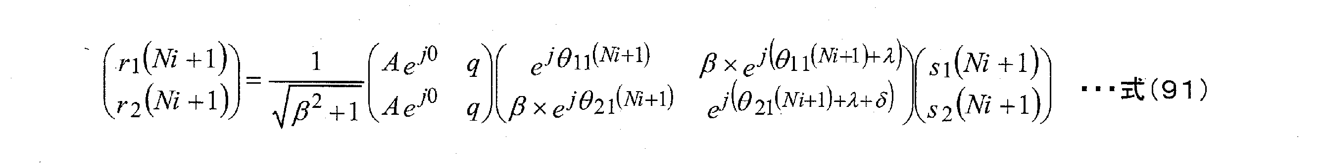
・
・
・
シンボル番号Ni+k(k=0、1、・・・、N-1)のとき:
・
・
・
When the symbol number Ni + k (k = 0, 1, ..., N-1):

・
・
・
シンボル番号Ni+N-1のとき:
・
・
・
When the symbol number is Ni + N-1:

ただし、式(90)~式(93)において、Aは実数であり、qは複素数であるものとする。そして、式(90)~式(93)を以下のようにあらわすものとする。
シンボル番号Niのとき(iは0以上の整数とする):
However, in equations (90) to (93), it is assumed that A is a real number and q is a complex number. Then, it is assumed that equations (90) to (93) are expressed as follows.
When the symbol number Ni (i is an integer of 0 or more):

ただし、jは虚数単位。
シンボル番号Ni+1のとき:
However, j is an imaginary unit.
When the symbol number is Ni + 1:

・
・
・
シンボル番号Ni+k(k=0、1、・・・、N-1)のとき:
・
・
・
When the symbol number Ni + k (k = 0, 1, ..., N-1):

・
・
・
シンボル番号Ni+N-1のとき:
・
・
・
When the symbol number is Ni + N-1:

すると、qが以下のようにあらわされるとき、s1、s2のいずれかの信号を得ることができなくなる。
シンボル番号Niのとき(iは0以上の整数とする):
Then, when q is expressed as follows, either the signal of s1 or s2 cannot be obtained.
When the symbol number Ni (i is an integer of 0 or more):

シンボル番号Ni+1のとき: When the symbol number is Ni + 1:

・
・
・
シンボル番号Ni+k(k=0、1、・・・、N-1)のとき:
・
・
・
When the symbol number Ni + k (k = 0, 1, ..., N-1):

・
・
・
シンボル番号Ni+N-1のとき:
・
・
・
When the symbol number is Ni + N-1:

このとき、シンボル番号N~Ni+N-1において、qが同一の解をもつと、直接波のチャネル要素は大きな変動がないため、いずれのシンボル番号においても、良好な受信品質を得ることができなくなるため、誤り訂正符号を導入しても、誤り訂正能力を得ることが難しい。したがって、qが同一の解をもたないためには、qの2つの解のうち、δを含まないほうの解に着目すると、式(98)~式(101)から、以下の条件が必要となる。 At this time, if q has the same solution in the symbol numbers N to Ni + N-1, the channel element of the direct wave does not have a large fluctuation, so that good reception quality cannot be obtained in any of the symbol numbers. Therefore, even if an error correction code is introduced, it is difficult to obtain an error correction capability. Therefore, in order for q not to have the same solution, focusing on the solution that does not include δ among the two solutions of q, the following conditions are required from equations (98) to (101). Will be.

(xは0,1,2,・・・,N-2,N-1であり、yは0,1,2,・・・,N-2,N-1であり、x≠yである。)
次に、θ11、θ12のみだけではなく、λ、δについての設計要件について説明する。λについ、ある値に設定すればよく、要件としては、δについての要件を与える必要がある。そこで、λを0ラジアンとした場合のδの設定方法について説明する。
(X is 0,1,2, ..., N-2, N-1, y is 0,1,2, ..., N-2, N-1, and x ≠ y. .)
Next, not only θ11 and θ12 but also design requirements for λ and δ will be described. It suffices to set a certain value for λ, and it is necessary to give a requirement for δ as a requirement. Therefore, a method of setting δ when λ is set to 0 radians will be described.
この場合、4スロット周期でプリコーディングウェイトを変更する方法のときと同様に、δに対し、π/2ラジアン≦|δ|≦πラジアン、とすると、特に、LOS環境におい
て、良好な受信品質を得ることができる。
In this case, as in the case of the method of changing the precoding weight in a 4-slot cycle, if π / 2 radians ≤ | δ | ≤ π radians for δ, good reception quality is obtained especially in the LOS environment. Obtainable.
シンボル番号Ni~Ni+N-1において、それぞれ、悪い受信品質となるqは2点存在する、したがって、2N点の点が存在することになる。LOS環境において、良好な特性を得るためには、これら2N点がすべて異なる解であるとよい。この場合、<条件#5>に加え、βは正の実数とし、β≠1であることを考慮すると、<条件#6>の条件が必要となる。
In the symbol numbers Ni to Ni + N-1, there are two points of q having poor reception quality, and therefore there are two points of points. In order to obtain good characteristics in the LOS environment, it is preferable that these 2N points are all different solutions. In this case, in addition to <

以上のように、MIMO伝送システムの送信装置が複数アンテナから複数の変調信号を送信する際、時間とともにプリコーディングウェイトを切り替えるとともに、切り替えを規則的に行うことで、直接波が支配的なLOS環境において、従来の空間多重MIMO伝送を用いるときと比べ、伝送品質が向上するという効果を得ることができる。 As described above, when the transmitter of the MIMO transmission system transmits a plurality of modulated signals from a plurality of antennas, the precoding weight is switched over time and the switching is performed regularly, so that the LOS environment in which the direct wave is dominant is dominated. In the above, it is possible to obtain the effect of improving the transmission quality as compared with the case of using the conventional spatial multiplex MIMO transmission.
本実施の形態において、受信装置の構成は、実施の形態1で説明したとおりであり、特に、受信装置の構成については、アンテナ数を限定して、動作を説明したが、アンテナ数が増えても、同様に実施することができる。つまり、受信装置におけるアンテナ数は、本実施の形態の動作、効果に影響を与えるものではない。また、本実施の形態では、実施の形態1と同様に、誤り訂正符号は限定されるものではない。 In the present embodiment, the configuration of the receiving device is as described in the first embodiment. In particular, regarding the configuration of the receiving device, the operation is described by limiting the number of antennas, but the number of antennas increases. Can be carried out in the same manner. That is, the number of antennas in the receiving device does not affect the operation and effect of the present embodiment. Further, in the present embodiment, the error correction code is not limited as in the first embodiment.
また、本実施の形態では、実施の形態1と対比させ、時間軸におけるプリコーディングウェイト変更方法について説明したが、実施の形態1で説明したように、マルチキャリア伝送方式を用い、周波数軸、周波数―時間軸に対し、シンボルを配置することで、プリコーディングウェイト変更方法しても同様に実施することができる。また、本実施の形態では、データシンボル以外のシンボル、例えば、パイロットシンボル(プリアンブル、ユニークワード等)、制御情報用のシンボルなどが、フレームにどのように配置されていてもよい。 Further, in the present embodiment, the method of changing the precoding weight on the time axis has been described in comparison with the first embodiment, but as described in the first embodiment, the multi-carrier transmission method is used, and the frequency axis and frequency are used. -By arranging symbols on the time axis, the precoding weight can be changed in the same way. Further, in the present embodiment, symbols other than the data symbols, for example, pilot symbols (preambles, unique words, etc.), symbols for control information, and the like may be arranged in the frame.
(実施の形態4)
実施の形態3では、プリコーディングウェイトを規則的に切り替える方式において、プリコーディングウェイトの行列の各要素の振幅を1とβ
の2種類の場合を例に説明した。
(Embodiment 4)
In the third embodiment, in the method of regularly switching the precoding weights, the amplitude of each element of the precoding weight matrix is set to 1 and β.
The two types of cases described above have been described as an example.
なお、ここでは、 In addition, here,

は無視している。
続いて、βの値をスロットで切り替える場合の例について説明する。
実施の形態3と対比するために、2×Nスロット周期で、プリコーディングウェイトを変更する場合について説明する。
Is ignoring.
Next, an example of switching the β value in the slot will be described.
In order to compare with the third embodiment, a case where the precoding weight is changed in a 2 × N slot period will be described.
実施の形態1、実施の形態2、実施の形態3と同様に考えると、シンボル番号に対し、以下であらわされるような処理を行うことになる。ただし、βは正の実数とし、β≠1とする。また、αは正の実数とし、α≠βとする。
シンボル番号2Niのとき(iは0以上の整数とする):
Considering in the same manner as in the first embodiment, the second embodiment, and the third embodiment, the symbol number is processed as shown below. However, β is a positive real number, and β ≠ 1. Also, α is a positive real number, and α ≠ β.
When the symbol number is 2Ni (i is an integer of 0 or more):

ただし、jは虚数単位。
シンボル番号2Ni+1のとき:
However, j is an imaginary unit.
When the symbol number is 2Ni + 1:

・
・
・
シンボル番号2Ni+k(k=0、1、・・・、N-1)のとき:
・
・
・
When the symbol number is 2Ni + k (k = 0, 1, ..., N-1):

・
・
・
シンボル番号2Ni+N-1のとき:
・
・
・
When the symbol number is 2Ni + N-1:

シンボル番号2Ni+Nのとき(iは0以上の整数とする): When the symbol number is 2Ni + N (i is an integer of 0 or more):

ただし、jは虚数単位。
シンボル番号2Ni+N+1のとき:
However, j is an imaginary unit.
When the symbol number is 2Ni + N + 1:

・
・
・
シンボル番号2Ni+N+k(k=0、1、・・・、N-1)のとき:
・
・
・
When the symbol number is 2Ni + N + k (k = 0, 1, ..., N-1):

・
・
・
シンボル番号2Ni+2N-1のとき:
・
・
・
When the symbol number is 2Ni + 2N-1:

よって、r1、r2は以下のようにあらわされる。
シンボル番号2Niのとき(iは0以上の整数とする):
Therefore, r1 and r2 are represented as follows.
When the symbol number is 2Ni (i is an integer of 0 or more):

ただし、jは虚数単位。
シンボル番号2Ni+1のとき:
However, j is an imaginary unit.
When the symbol number is 2Ni + 1:

・
・
・
シンボル番号2Ni+k(k=0、1、・・・、N-1)のとき:
・
・
・
When the symbol number is 2Ni + k (k = 0, 1, ..., N-1):

・
・
・
シンボル番号2Ni+N-1のとき:
・
・
・
When the symbol number is 2Ni + N-1:

シンボル番号2Ni+Nのとき(iは0以上の整数とする): When the symbol number is 2Ni + N (i is an integer of 0 or more):

ただし、jは虚数単位。
シンボル番号2Ni+N+1のとき:
However, j is an imaginary unit.
When the symbol number is 2Ni + N + 1:

・
・
・
シンボル番号2Ni+N+k(k=0、1、・・・、N-1)のとき:
・
・
・
When the symbol number is 2Ni + N + k (k = 0, 1, ..., N-1):

・
・
・
シンボル番号2Ni+2N-1のとき:
・
・
・
When the symbol number is 2Ni + 2N-1:

このとき、チャネル要素h11(t)、h12(t)、h21(t)、h22(t)において、直接波の成分しか存在しないと仮定し、その直接波の成分の振幅成分は全て等しく、また、時間において、変動が起こらないとする。すると、式(110)~式(117)は以下のようにあらわすことができる。
シンボル番号2Niのとき(iは0以上の整数とする):
At this time, it is assumed that only the direct wave component exists in the channel elements h 11 (t), h 12 (t), h 21 (t), and h 22 (t), and the amplitude component of the direct wave component is It is assumed that they are all equal and that there is no fluctuation over time. Then, the equations (110) to (117) can be expressed as follows.
When the symbol number is 2Ni (i is an integer of 0 or more):

ただし、jは虚数単位。
シンボル番号2Ni+1のとき:
However, j is an imaginary unit.
When the symbol number is 2Ni + 1:

・
・
・
シンボル番号2Ni+k(k=0、1、・・・、N-1)のとき:
・
・
・
When the symbol number is 2Ni + k (k = 0, 1, ..., N-1):

・
・
・
シンボル番号2Ni+N-1のとき:
・
・
・
When the symbol number is 2Ni + N-1:

シンボル番号2Ni+Nのとき(iは0以上の整数とする): When the symbol number is 2Ni + N (i is an integer of 0 or more):

ただし、jは虚数単位。
シンボル番号2Ni+N+1のとき:
However, j is an imaginary unit.
When the symbol number is 2Ni + N + 1:

・
・
・
シンボル番号2Ni+N+k(k=0、1、・・・、N-1)のとき:
・
・
・
When the symbol number is 2Ni + N + k (k = 0, 1, ..., N-1):

・
・
・
シンボル番号2Ni+2N-1のとき:
・
・
・
When the symbol number is 2Ni + 2N-1:

ただし、式(118)~式(125)において、Aは実数であり、qは複素数であるものとする。そして、式(118)~式(125)を以下のようにあらわすものとする。
シンボル番号2Niのとき(iは0以上の整数とする):
However, in equations (118) to (125), it is assumed that A is a real number and q is a complex number. Then, equations (118) to (125) are expressed as follows.
When the symbol number is 2Ni (i is an integer of 0 or more):

ただし、jは虚数単位。
シンボル番号2Ni+1のとき:
However, j is an imaginary unit.
When the symbol number is 2Ni + 1:

・
・
・
シンボル番号2Ni+k(k=0、1、・・・、N-1)のとき:
・
・
・
When the symbol number is 2Ni + k (k = 0, 1, ..., N-1):

・
・
・
シンボル番号2Ni+N-1のとき:
・
・
・
When the symbol number is 2Ni + N-1:

シンボル番号2Ni+Nのとき(iは0以上の整数とする): When the symbol number is 2Ni + N (i is an integer of 0 or more):

ただし、jは虚数単位。
シンボル番号2Ni+N+1のとき:
However, j is an imaginary unit.
When the symbol number is 2Ni + N + 1:

・
・
・
シンボル番号2Ni+N+k(k=0、1、・・・、N-1)のとき:
・
・
・
When the symbol number is 2Ni + N + k (k = 0, 1, ..., N-1):

・
・
・
シンボル番号2Ni+2N-1のとき:
・
・
・
When the symbol number is 2Ni + 2N-1:

すると、qが以下のようにあらわされるとき、s1、s2のいずれかの信号を得ることができなくなる。
シンボル番号2Niのとき(iは0以上の整数とする):
Then, when q is expressed as follows, either the signal of s1 or s2 cannot be obtained.
When the symbol number is 2Ni (i is an integer of 0 or more):

シンボル番号2Ni+1のとき: When the symbol number is 2Ni + 1:

・
・
・
シンボル番号2Ni+k(k=0、1、・・・、N-1)のとき:
・
・
・
When the symbol number is 2Ni + k (k = 0, 1, ..., N-1):

・
・
・
シンボル番号2Ni+N-1のとき:
・
・
・
When the symbol number is 2Ni + N-1:

シンボル番号2Ni+Nのとき(iは0以上の整数とする): When the symbol number is 2Ni + N (i is an integer of 0 or more):

シンボル番号2Ni+N+1のとき: When the symbol number is 2Ni + N + 1:

・
・
・
シンボル番号2Ni+N+k(k=0、1、・・・、N-1)のとき:
・
・
・
When the symbol number is 2Ni + N + k (k = 0, 1, ..., N-1):

・
・
・
シンボル番号2Ni+2N-1のとき:
・
・
・
When the symbol number is 2Ni + 2N-1:

このとき、シンボル番号2N~2Ni+N-1において、qが同一の解をもつと、直接波のチャネル要素は大きな変動がないため、いずれのシンボル番号においても、良好な受信品質を得ることができなくなるため、誤り訂正符号を導入しても、誤り訂正能力を得ることが難しい。したがって、qが同一の解をもたないためには、qの2つの解のうち、δを含まないほうの解に着目すると、式(134)~式(141)および、α≠βより、<条件#7>または<条件#8>が必要となる。
At this time, if q has the same solution in the symbol numbers 2N to 2Ni + N-1, the channel element of the direct wave does not have a large fluctuation, so that good reception quality cannot be obtained in any of the symbol numbers. Therefore, even if an error correction code is introduced, it is difficult to obtain an error correction capability. Therefore, in order for q not to have the same solution, focusing on the solution that does not include δ among the two solutions of q, from equations (134) to (141) and α ≠ β, <


このとき、<条件#8>は、実施の形態1~実施の形態3で述べた条件と、同様の条件であるが、<条件#7>は、α≠βであるが故に、qの2つの解のうち、δを含まないほうの解は、異なる解を持つことになる。
At this time, <
次に、θ11、θ12のみだけではなく、λ、δについての設計要件について説明する。λについ、ある値に設定すればよく、要件としては、δについての要件を与える必要がある。そこで、λを0ラジアンとした場合のδの設定方法について説明する。 Next, not only θ11 and θ12 but also design requirements for λ and δ will be described. It suffices to set a certain value for λ, and it is necessary to give a requirement for δ as a requirement. Therefore, a method of setting δ when λ is set to 0 radians will be described.
この場合、4スロット周期でプリコーディングウェイトを変更する方法のときと同様に
、δに対し、π/2ラジアン≦|δ|≦πラジアン、とすると、特に、LOS環境において、良好な受信品質を得ることができる。
In this case, as in the case of the method of changing the precoding weight in a 4-slot cycle, if π / 2 radians ≤ | δ | ≤ π radians for δ, good reception quality is obtained especially in the LOS environment. Obtainable.
シンボル番号2Ni~2Ni+2N-1において、それぞれ、悪い受信品質となるqは2点存在する、したがって、4N点の点が存在することになる。LOS環境において、良好な特性を得るためには、これら4N点がすべて異なる解であるとよい。このとき、振幅に着目すると、<条件#7>または<条件#8>に対して、α≠βであるので以下の条件が必要となる。
In the symbol numbers 2Ni to 2Ni + 2N-1, there are two points of q having poor reception quality, and therefore there are points of 4N points. In order to obtain good characteristics in the LOS environment, it is preferable that these 4N points are all different solutions. At this time, focusing on the amplitude, since α ≠ β for <

以上のように、MIMO伝送システムの送信装置が複数アンテナから複数の変調信号を送信する際、時間とともにプリコーディングウェイトを切り替えるとともに、切り替えを規則的に行うことで、直接波が支配的なLOS環境において、従来の空間多重MIMO伝送を用いるときと比べ、伝送品質が向上するという効果を得ることができる。 As described above, when the transmitter of the MIMO transmission system transmits a plurality of modulated signals from a plurality of antennas, the precoding weight is switched over time and the switching is performed regularly, so that the LOS environment in which the direct wave is dominant is dominated. In the above, it is possible to obtain the effect of improving the transmission quality as compared with the case of using the conventional spatial multiplex MIMO transmission.
本実施の形態において、受信装置の構成は、実施の形態1で説明したとおりであり、特に、受信装置の構成については、アンテナ数を限定して、動作を説明したが、アンテナ数が増えても、同様に実施することができる。つまり、受信装置におけるアンテナ数は、本実施の形態の動作、効果に影響を与えるものではない。また、本実施の形態では、実施の形態1と同様に、誤り訂正符号は限定されるものではない。 In the present embodiment, the configuration of the receiving device is as described in the first embodiment. In particular, regarding the configuration of the receiving device, the operation is described by limiting the number of antennas, but the number of antennas increases. Can be carried out in the same manner. That is, the number of antennas in the receiving device does not affect the operation and effect of the present embodiment. Further, in the present embodiment, the error correction code is not limited as in the first embodiment.
また、本実施の形態では、実施の形態1と対比させ、時間軸におけるプリコーディングウェイト変更方法について説明したが、実施の形態1で説明したように、マルチキャリア伝送方式を用い、周波数軸、周波数―時間軸に対し、シンボルを配置することで、プリコーディングウェイトを変更しても同様に実施することができる。また、本実施の形態では、データシンボル以外のシンボル、例えば、パイロットシンボル(プリアンブル、ユニークワード等)、制御情報用のシンボルなどが、フレームにどのように配置されていてもよい。 Further, in the present embodiment, the method of changing the precoding weight on the time axis has been described in comparison with the first embodiment, but as described in the first embodiment, the multi-carrier transmission method is used, and the frequency axis and frequency are used. -By arranging symbols on the time axis, it can be implemented in the same way even if the precoding weight is changed. Further, in the present embodiment, symbols other than the data symbols, for example, pilot symbols (preambles, unique words, etc.), symbols for control information, and the like may be arranged in the frame.
(実施の形態5)
実施の形態1~実施の形態4では、プリコーディングウェイトを規則的に切り替える方法について説明したが、本実施の形態では、その変形例について説明する。
(Embodiment 5)
In the first to fourth embodiments, a method of regularly switching the precoding weights has been described, but in the present embodiment, a modified example thereof will be described.
実施の形態1~実施の形態4では、プリコーディングウェイトを図6のように規則的に切り替える方法について説明した。本実施の形態では、図6とは異なる規則的にプリコーディングウェイトを切り替える方法について説明する。 In the first to fourth embodiments, a method of regularly switching the precoding weights as shown in FIG. 6 has been described. In the present embodiment, a method of regularly switching the precoding weights, which is different from that in FIG. 6, will be described.
図6と同様に、4つの異なるプリコーディングウェイト(行列)を切り替える方式で、図6とは異なる切り替え方法に関する図を図22に示す。図22において、4つの異なるプリコーディングウェイト(行列)をW1、W2、W3、W4とあらわすものとする。(
例えば、W1を式(37)におけるプリコーディングウェイト(行列)、W2を式(38)におけるプリコーディングウェイト(行列)、W3を式(39)におけるプリコーディングウェイト(行列)、W4を式(40)におけるプリコーディングウェイト(行列)とする。)そして、図3と図6と同様に動作するものについては同一符号を付している。図22において、固有な部分は、
・第1の周期2201、第2の周期2202、第3の周期2203、・・・はすべて、4スロットで構成されている。
・4スロットではスロットごとに異なるプリコーディングウェイト行列、つまり、W1、W2、W3、W4をそれぞれ1度用いる。
・第1の周期2201、第2の周期2202、第3の周期2203、・・・において、必ずしもW1、W2、W3、W4の順番を同一とする必要がない。
である。これを実現するために、プリコーディングウェイト行列生成部2200は重み付け方法に関する信号を入力とし、各周期における順番にしたがったプリコーディングウェイトに関する情報2210を出力する。そして、重み付け合成部600は、この信号と、s1(t)、s2(t)を入力とし、重み付け合成を行い、z1(t)、z2(t)を出力する。
Similar to FIG. 6, FIG. 22 shows a diagram relating to a switching method different from that of FIG. 6 in a method of switching four different precoding weights (matrix). In FIG. 22, four different precoding weights (matrix) are represented as W 1 , W 2 , W 3 , and W 4 . ((
For example, W 1 is the precoding weight (matrix) in the equation (37), W 2 is the precoding weight (matrix) in the equation (38), W 3 is the precoding weight (matrix) in the equation (39), and W 4 is. It is a precoding weight (matrix) in the equation (40). ) And those that operate in the same manner as in FIGS. 3 and 6 are designated by the same reference numerals. In FIG. 22, the unique part is
The
-In 4 slots, a different precoding weight matrix for each slot, that is, W 1 , W 2 , W 3 , and W 4 are used once.
-In the
Is. In order to realize this, the precoding weight
図23は、上述のプリコーディング方法に対し、図22とは重み付け合成方法を示している。図23において、図22の異なる点は、重み付け合成部以降に並び換え部を配置し、信号の並び換えを行うことで、図22と同様な方法を実現している点である。 FIG. 23 shows a weighted synthesis method with respect to FIG. 22 as opposed to the above-mentioned precoding method. In FIG. 23, the difference in FIG. 22 is that the same method as in FIG. 22 is realized by arranging the rearrangement unit after the weighting synthesis unit and rearranging the signals.
図23において、プリコーディングウェイト生成部2200は、重み付け方法に関する情報315を入力とし、プリコーディングウェイトW1、W2、W3、W4、W1、W2、W3、W4、・・・の順にプリコーディングウェイトの情報2210を出力する。したがって、重み付け合成部600は、プリコーディングウェイトW1、W2、W3、W4、W1、W2、W3、W4、・・・の順にプリコーディングウェイトを用い、プリコーディング後の信号2300A、2300Bを出力する。
In FIG. 23, the precoding
並び替え部2300は、プリコーディング後の信号2300A、2300Bを入力とし、図23の第1の周期2201、第2の周期2202、第3の周期2203の順番となるように、プリコーディング後の信号2300A、2300Bについて並び換えを行い、z1(t)、z2(t)を出力する。
The
なお、上述では、プリコーディングウェイトの切り替え周期を図6と比較するために4として説明したが、実施の形態1~実施の形態4のように、周期4以外のときでも同様に実施することが可能である。
In the above, the switching cycle of the precoding weight has been described as 4 in order to compare it with FIG. 6, but it can be similarly carried out at times other than the
また、実施の形態1~実施の形態4、および、上述のプリコーディング方法において、周期内では、δ、βの値をスロットごとに同一であるとして説明したが、スロットごとにδ、βの値を切り替えるようにしてもよい。 Further, in the first to fourth embodiments and the above-mentioned precoding method, the values of δ and β are described as being the same for each slot in the cycle, but the values of δ and β for each slot are described. May be switched.
以上のように、MIMO伝送システムの送信装置が複数アンテナから複数の変調信号を送信する際、時間とともにプリコーディングウェイトを切り替えるとともに、切り替えを規則的に行うことで、直接波が支配的なLOS環境において、従来の空間多重MIMO伝送を用いるときと比べ、伝送品質が向上するという効果を得ることができる。 As described above, when the transmitter of the MIMO transmission system transmits a plurality of modulated signals from a plurality of antennas, the precoding weight is switched over time and the switching is performed regularly, so that the LOS environment in which the direct wave is dominant is dominated. In the above, it is possible to obtain the effect of improving the transmission quality as compared with the case of using the conventional spatial multiplex MIMO transmission.
本実施の形態において、受信装置の構成は、実施の形態1で説明したとおりであり、特に、受信装置の構成については、アンテナ数を限定して、動作を説明したが、アンテナ数が増えても、同様に実施することができる。つまり、受信装置におけるアンテナ数は、本実施の形態の動作、効果に影響を与えるものではない。また、本実施の形態では、実施の
形態1と同様に、誤り訂正符号は限定されるものではない。
In the present embodiment, the configuration of the receiving device is as described in the first embodiment. In particular, regarding the configuration of the receiving device, the operation is described by limiting the number of antennas, but the number of antennas increases. Can be carried out in the same manner. That is, the number of antennas in the receiving device does not affect the operation and effect of the present embodiment. Further, in the present embodiment, the error correction code is not limited as in the first embodiment.
また、本実施の形態では、実施の形態1と対比させ、時間軸におけるプリコーディングウェイト変更方法について説明したが、実施の形態1で説明したように、マルチキャリア伝送方式を用い、周波数軸、周波数―時間軸に対し、シンボルを配置することで、プリコーディングウェイト変更方法しても同様に実施することができる。また、本実施の形態では、データシンボル以外のシンボル、例えば、パイロットシンボル(プリアンブル、ユニークワード等)、制御情報用のシンボルなどが、フレームにどのように配置されていてもよい。 Further, in the present embodiment, the method of changing the precoding weight on the time axis has been described in comparison with the first embodiment, but as described in the first embodiment, the multi-carrier transmission method is used, and the frequency axis and frequency are used. -By arranging symbols on the time axis, the precoding weight can be changed in the same way. Further, in the present embodiment, symbols other than the data symbols, for example, pilot symbols (preambles, unique words, etc.), symbols for control information, and the like may be arranged in the frame.
(実施の形態6)
実施の形態1~4において、プリコーディングウェイトを規則的に切り替える方法について述べたが、本実施の形態では、実施の形態1~4で述べた内容を含め、再度、プリコーディングウェイトを規則的に切り替える方法について説明する。
(Embodiment 6)
Although the method of regularly switching the precoding weights has been described in the first to fourth embodiments, in the present embodiment, the precoding weights are regularly switched again including the contents described in the first to fourth embodiments. The method of switching is explained.
ここでは、まず、LOS環境を考慮した、通信相手からのフィードバックが存在しないプ
リコーディングを適用した空間多重型の2x2MIMOシステムのプリコーディング行列の設計
方法について述べる。
Here, first, the design method of the precoding matrix of the spatial multiplex type 2x2 MIMO system to which the precoding without feedback from the communication partner is applied in consideration of the LOS environment will be described.
図30は、通信相手からのフィードバックが存在しないプリコーディングを適用した空間多重型の2x2MIMOシステムモデルを示している。情報ベクトルzは、符号化およびインタリーブが施される。そして、インタリーブの出力として、符号化後ビットのベクトルu(p)=(u1(p),u2(p))が得られる(pはスロット時間である。)。ただし、ui(p)=(ui1(p)…,uih(p))とする(h:シンボル当たりの送信ビット数)。変調後(マッピング後)の信号をs(p)=(s1(p),s2(p))Tとすると、プリコーディング行列をF(p)とするとプリコーディング後の
信号x(p)=(x1(p),x2(p))Tは次式であらわされる。
FIG. 30 shows a spatially multiplexed 2x2 MIMO system model to which precoding is applied in which there is no feedback from the communication partner. The information vector z is coded and interleaved. Then, as the output of the interleave, the vector u (p) = (u 1 (p), u 2 (p)) of the encoded bits is obtained (p is the slot time). However, u i (p) = (u i1 (p)…, u ih (p)) (h: number of transmission bits per symbol). If the signal after modulation (after mapping) is s (p) = (s 1 (p), s 2 (p)) T , and if the precoding matrix is F (p), the signal after precoding x (p) = (x 1 (p), x 2 (p)) T is expressed by the following equation.

したがって、受信ベクトルをy(p)=(y1(p), y2(p))Tとすると、次式であらわされる。 Therefore, if the received vector is y (p) = (y 1 (p), y 2 (p)) T , it is expressed by the following equation.

このとき、H(p)はチャネル行列、n(p)=(n1(p),n2(p))Tはノイズベクトルであり、ni(p)は平均値0、分散σ2のi.i.d.複素ガウス雑音である。そして、ライスファクタをKとした
とき、上式は、以下のようにあらわすことができる。
At this time, H (p) is the channel matrix, n (p) = (n 1 (p), n 2 (p)) T is the noise vector, n i (p) is the

このとき、Hd(p)は直接波成分のチャネル行列、Hs(p)は散乱波成分のチャネル行列である。したがって、チャネル行列H(p)を以下のようにあらわす。 At this time, H d (p) is the channel matrix of the direct wave component, and H s (p) is the channel matrix of the scattered wave component. Therefore, the channel matrix H (p) is expressed as follows.

式(145)において、直接波の環境は通信機同士の位置関係で一意に決定すると仮定し、直接波成分のチャネル行列Hd(p)は時間的には変動がないものとする。また、直接波
成分のチャネル行列Hd(p)において、送信アンテナ間隔と比較し、送受信機間の距離が十
分長い環境となる可能性が高いため、直接波成分のチャネル行列正則行列であるものとする。したがって、チャネル行列Hd(p)を以下のようにあらわすものとする。
In equation (145), it is assumed that the environment of the direct wave is uniquely determined by the positional relationship between the communication devices, and the channel matrix H d (p) of the direct wave component does not fluctuate in time. In addition, the channel matrix H d (p) of the direct wave component is a regular matrix of the channel matrix of the direct wave component because there is a high possibility that the distance between the transmitter and receiver will be sufficiently longer than the transmission antenna interval. And. Therefore, the channel matrix H d (p) is expressed as follows.

ここで、Aは正の実数であり、qは複素数であるものとする。以下では、LOS環境を考慮
した、通信相手からのフィードバックが存在しないプリコーディングを適用した空間多重型の2x2MIMOシステムのプリコーディング行列の設計方法について述べる。
Here, it is assumed that A is a positive real number and q is a complex number. In the following, we describe how to design the precoding matrix of a spatially multiplexed 2x2 MIMO system that applies precoding that does not have feedback from the communication partner, considering the LOS environment.
式(144),(145)から、散乱波を含んだ状態での解析は困難であることから、散乱波を含んだ状態で適切なフィードバックなしのプリコーディング行列を求めるのは困難となる。加えて、NLOS環境では、LOS環境と比較し、データの受信品質の劣化が少ない
。したがって、LOS環境での適切なフィードバックなしのプリコーディング行列の設計方
法(時間とともにプリコーディング行列を切り替えるプリコーディング方法のプリコーディング行列)について述べる。
From the equations (144) and (145), it is difficult to analyze the state including the scattered wave, so that it is difficult to obtain the precoding matrix without the appropriate feedback in the state containing the scattered wave. In addition, the NLOS environment has less deterioration in data reception quality than the LOS environment. Therefore, the design method of the precoding matrix without appropriate feedback in the LOS environment (precoding matrix of the precoding method of switching the precoding matrix with time) will be described.
上述したように、式(144),(145)から、散乱波を含んだ状態での解析は困難であることから、直接波のみの成分を含むチャネル行列において、適切なプリコーディング行列を求めることにする。したがって、式(144)において、チャネル行列が直接波のみの成分を含む場合を考える。したがって、式(146)から、以下のようにあらわすことができる。 As described above, since it is difficult to analyze the state including the scattered wave from the equations (144) and (145), an appropriate precoding matrix should be obtained in the channel matrix containing only the direct wave component. To. Therefore, in Eq. (144), consider the case where the channel matrix contains only the direct wave component. Therefore, it can be expressed as follows from the equation (146).

ここで、プリコーディング行列として、ユニタリ行列を用いるものとする。したがって、プリコーディング行列を以下のようにあらわす。 Here, it is assumed that a unitary matrix is used as the precoding matrix. Therefore, the precoding matrix is expressed as follows.

このときλは固定値である。したがって、式(147)は、以下のようにあらわすことができる。 At this time, λ is a fixed value. Therefore, the equation (147) can be expressed as follows.

式(149)からわかるように、受信機がZF(zero forcing)やMMSE(minimum mean squared error)の線形演算を行った場合、s1(p), s2(p)によって送信したビットを判定することはできない。このことから、実施の形態1で述べたような反復APP(または、反復Max-log APP)またはAPP(または、Max-log APP)を行い(以降ではML(Maximum Likelihood)演算とよぶ)、s1(p), s2(p)で送信した各ビットの対数尤度比を求め、誤り訂正符号における復号を行うことになる。したがって、ML演算を行う受信機に対するLOS環境での
適切なフィードバックなしのプリコーディング行列の設計方法について説明する。
As can be seen from equation (149), when the receiver performs a linear operation of ZF (zero forcing) or MMSE (minimum mean squared error), the bits transmitted by s 1 (p) and s 2 (p) are determined. You can't. For this reason, the iterative APP (or iterative Max-log APP) or APP (or Max-log APP) as described in the first embodiment is performed (hereinafter referred to as ML (Maximum Likelihood) operation), and s. The log-likelihood ratio of each bit transmitted in 1 (p) and s 2 (p) is obtained, and decoding is performed with the error correction code. Therefore, a method of designing a precoding matrix without appropriate feedback in the LOS environment for a receiver performing ML operation will be described.
式(149)におけるプリコーディングを考える。1行目の右辺、および、左辺にe-jΨを乗算し、同様に、2行目の右辺、および、左辺にe-jΨを乗算する。すると、次式のようにあらわされる。 Consider the precoding in equation (149). Multiply the right and left sides of the first line by e -jΨ , and similarly multiply the right and left sides of the second line by e -jΨ . Then, it is expressed as the following equation.

e-jΨy1(p), e-jΨy2(p), e-jΨqをそれぞれy1(p), y2(p), qと再定義し、また、e-jΨn(p)=(e-jΨn1(p), e-jΨn2(p))Tとなり、e-jΨn1(p), e-jΨn2(p)は平均値0、分散σ2のi.i.d.(independent identically distributed)複素ガウス雑音となるので、e-jΨn(p)をn(p)と再定義する。すると、式(150)を式(151)のようにしても一般性は失われていない。 Redefine e -j Ψ y 1 (p), e -j Ψ y 2 (p), e -j Ψ q as y 1 (p), y 2 (p), q, respectively, and e -j Ψ n (p). ) = (e -jΨ n 1 (p), e -jΨ n 2 (p)) T , and e -jΨ n 1 (p), e -jΨ n 2 (p) have an average value of 0 and a variance of σ 2 . iid (independent identically distributed) Since it becomes complex Gaussian noise, e -j Ψ n (p) is redefined as n (p). Then, even if the equation (150) is changed to the equation (151), the generality is not lost.

次に、式(151)を理解しやすいように式(152)のように変形する。 Next, the equation (151) is transformed into the equation (152) so as to be easy to understand.

このとき、受信信号点と受信候補信号点とのユークリッド距離の最小値をdmin
2とした
とき、dmin
2がゼロという最小値をとる劣悪点であるとともに、s1(p)で送信するすべてのビット、または、s2(p)で送信するすべてのビットが消失するという劣悪な状態となるqが2つ存在する。
At this time, when the minimum value of the Euclidean distance between the received signal point and the received candidate signal point is d min 2 , it is a bad point that d min 2 takes the minimum value of zero, and it is transmitted at s 1 (p). There are two qs that are in a bad state where all the bits or all the bits transmitted by s 2 (p) are lost.
式(152)においてs1(p)が存在しない: S 1 (p) does not exist in equation (152):

式(152)においてs2(p)が存在しない: S 2 (p) does not exist in equation (152):

(以降では、式(153),(154)を満たすqをそれぞれ「s1, s2の受信劣悪点」
と呼ぶ)
式(153)を満たすとき、s1(p)により送信したビットすべてが消失しているためs1(p)により送信したビットすべての受信対数尤度比を求めることができず、式(154)を満たすとき、s2(p)により送信したビットすべてが消失しているためs2(p)により送信したビットすべての受信対数尤度比を求めることができない。
(Hereafter, q that satisfies equations (153) and (154) is "reception inferior point of s 1 and s 2 , respectively".
Call)
When the equation (153) is satisfied, since all the bits transmitted by s 1 (p) are lost, the received log-likelihood ratio of all the bits transmitted by s 1 (p) cannot be obtained, and the equation (154) cannot be obtained. ), Since all the bits transmitted by s 2 (p) are lost, the received log-likelihood ratio of all the bits transmitted by s 2 (p) cannot be obtained.
ここで、プリコーディング行列を切り替えない場合の放送・マルチキャスト通信システムを考える。このとき、プリコーディング行列を切り替えないプリコーディング方式を用いて変調信号を送信する基地局あり、基地局が送信した変調信号を受信する端末が複数(Γ個)存在するシステムモデルを考える。 Here, consider a broadcasting / multicast communication system in which the precoding matrix is not switched. At this time, consider a system model in which there is a base station that transmits a modulated signal using a precoding method that does not switch the precoding matrix, and there are a plurality of terminals (Γ) that receive the modulated signal transmitted by the base station.
基地局・端末間の直接波の状況は、時間による変化は小さいと考えられる。すると、式(153),(154)から、式(155)または式(156)の条件にあてはまるような位置にあり、ライスファクタが大きいLOS環境にある端末は、データの受信品質が劣化
するという現象に陥る可能性がある。したがって、この問題を改善するためは、時間的にプリコーディング行列を切り替える必要がある。
The situation of direct waves between the base station and the terminal is considered to change little with time. Then, from equations (153) and (154), a terminal in an LOS environment that is in a position that meets the conditions of equation (155) or equation (156) and has a large rice factor is said to have deteriorated data reception quality. There is a possibility of falling into a phenomenon. Therefore, in order to improve this problem, it is necessary to switch the precoding matrix in time.


そこで、時間周期をNスロットとし、規則的にプリコーディング行列を切り替える方法
(以降ではプリコーディングホッピング方法と呼ぶ)を考える。
時間周期Nスロットのために、式(148)に基づくN種類のプリコーディング行列F[i]を用意する(i=0,1,…,N-1)。このとき、プリコーディング行列F[i]を以下のようにあらわす。
Therefore, consider a method (hereinafter referred to as a precoding hopping method) in which the time period is set to N slots and the precoding matrix is regularly switched.
For the time period N slot, N kinds of precoding matrices F [i] based on the equation (148) are prepared (i = 0,1, ..., N-1). At this time, the precoding matrix F [i] is expressed as follows.

ここで、αは時間的に変化しないものとし、λも時間的に変化しないものとする(変化させてもよい。)。
そして、実施の形態1と同様に、時点(時刻)N×k+i(kは0以上の整数、i=0,1,…,N-1)の式(142)におけるプリコーディング後の信号x(p= N×k+i)を得るために用いられるプ
リコーディング行列がF[i]となる。これについては、以降でも同様である。
Here, it is assumed that α does not change with time, and λ does not change with time (may be changed).
Then, as in the first embodiment, the signal after precoding in the equation (142) of the time point (time) N × k + i (k is an integer of 0 or more, i = 0,1, ..., N-1). The precoding matrix used to obtain x (p = N × k + i) is F [i]. The same applies to this thereafter.
このとき、式 (153),(154)に基づき、以下のようなプリコーディングホッ
ピングのプリコーディング行列の設計条件が重要となる。
At this time, based on the equations (153) and (154), the following precoding matrix design conditions for precoding hopping are important.


<条件#10>により、Γ個の端末すべてにおいて、時間周期内のNにおいて、s1の受
信劣悪点をとるスロットは1スロット以下となる。したがって、N-1スロット以上s1(p)で
送信したビットの対数尤度比を得ることができる。同様に、<条件#11>により、Γ個の端末すべてにおいて、時間周期内のNにおいて、s2の受信劣悪点をとるスロットは1スロット以下となる。したがって、N-1スロット以上s2(p)で送信したビットの対数尤度比を得ることができる。
According to <
このように、<条件#10>、<条件#11>のプリコーディング行列の設計規範を与えることで、s1(p)で送信したビットの対数尤度比が得られるビット数、および、s2(p)で送信したビットの対数尤度比が得られるビット数をΓ個の端末すべてにおいて一定数以上
に保証することで、Γ個の端末すべてにおいて、ライスファクタが大きいLOS環境でのデ
ータ受信品質の劣化を改善することを考える。
In this way, by giving the design norms of the precoding matrix of <
以下では、プリコーディングホッピング方法におけるプリコーディング行列の例を記載する。
直接波の位相の確率密度分布は[0 2π]の一様分布であると考えることができる。した
がって、式(151),(152)におけるqの位相の確率密度分布も[0 2π]の一様分布であると考えることができる。よって、qの位相のみが異なる同一のLOS環境において、Γ個の端末に対し、可能な限り公平なデータの受信品質を与えるための条件として、以下を与える。
<条件#12>
時間周期Nスロットのプリコーディングホッピング方法を用いた場合、時間周期内のNにおいて、s1の受信劣悪点を位相に対し一様分布となるように配置し、かつ、s2の受信劣悪点を位相に対し一様分布となるように配置する。
The following describes an example of the precoding matrix in the precoding hopping method.
The probability density distribution of the phase of the direct wave can be considered to be a uniform distribution of [0 2π]. Therefore, it can be considered that the probability density distribution of the phase of q in Eqs. (151) and (152) is also a uniform distribution of [0 2π]. Therefore, in the same LOS environment where only the phase of q is different, the following are given as conditions for giving as fair data reception quality as possible to Γ terminals.
<
When the precoding hopping method of the time cycle N slot is used, the reception poor points of s 1 are arranged so as to be uniformly distributed with respect to the phase at N in the time cycle, and the reception poor points of s 2 are set. Arrange so that the distribution is uniform with respect to the phase.
そこで、<条件#10>から<条件#12>に基づくプリコーディングホッピング方法におけるプリコーディング行列の例を説明する。式(157)のプリコーディング行列のα=1.0とする。
(例#5)
時間周期N=8とし、<条件#10>から<条件#12>を満たすために、次式のような
時間周期N=8のプリコーディングホッピング方法におけるプリコーディング行列を与える
。
Therefore, an example of the precoding matrix in the precoding hopping method based on <
(Example # 5)
In order to satisfy <

ただし、jは虚数単位であり、i=0,1,…,7である。式(160)のかわりに式(161)と与えてもよい(λ、θ11[i]は時間的に変化しないものとする(変化してもよい)。
)。
However, j is an imaginary unit, and i = 0,1, ..., 7. Instead of Eq. (160), Eq. (161) may be given (λ, θ 11 [i] shall not change over time (may change).
).

したがって、s1, s2の受信劣悪点は図31(a)(b)のようになる。(図31において、横軸は実軸、縦軸は虚軸となる。)また、式(160)、式(161)のかわりに式(162)、式(163)と与えてもよい(i=0,1,…,7)(λ、θ11[i]は時間的に変化しない
ものとする(変化してもよい)。)。
Therefore, the reception inferior points of s 1 and s 2 are as shown in FIGS. 31 (a) and 31 (b). (In FIG. 31, the horizontal axis is the real axis and the vertical axis is the imaginary axis.) Further, the equations (162) and (163) may be given instead of the equations (160) and (161) (i). = 0,1, ..., 7) (λ, θ 11 [i] shall not change over time (may change)).


次に、条件12とは異なる、qの位相のみが異なる同一のLOS環境において、Γ個の端末に対し、可能な限り公平なデータの受信品質を与えるための条件として、以下を与える。<条件#13>
時間周期Nスロットのプリコーディングホッピング方法を用いた場合、
Next, in the same LOS environment different from the
When using the precoding hopping method of the time cycle N slot,

の条件を付加し、また、時間周期内のNにおいて、s1の受信劣悪点を位相とs2の受信劣悪
点を位相に対し、一様分布となるように配置する。
そこで、<条件#10>, <条件#11>, <条件#13>に基づくプリコーディングホッピング方法におけるプリコーディング行列の例を説明する。式(157)のプリコーディング行列のα=1.0とする。
(例#6)
時間周期N=4とし、次式のような時間周期N=4のプリコーディングホッピング方法におけるプリコーディング行列を与える。
The condition of is added, and the reception inferior points of s 1 are arranged so as to have a uniform distribution with respect to the phase and the reception inferior points of s 2 are arranged at N in the time cycle.
Therefore, an example of the precoding matrix in the precoding hopping method based on <
(Example # 6)
Let the time period N = 4, and give the precoding matrix in the precoding hopping method with the time period N = 4 as shown in the following equation.

ただし、jは虚数単位であり、i=0,1,2,3である。式(165)のかわりに式(166
)と与えてもよい(λ、θ11[i]は時間的に変化しないものとする(変化してもよい)。
)。
However, j is an imaginary unit, and i = 0,1,2,3. Equation (166) instead of Equation (165)
) May be given (λ, θ 11 [i] shall not change over time (may change).
).

したがって、s1, s2の受信劣悪点は図32のようになる。(図32において、横軸は実軸、縦軸は虚軸となる。)また、式(165)、式(166)のかわりに式(167)、式(168)と与えてもよい(i=0,1,2,3)(λ、θ11[i]は時間的に変化しないものとする(変化してもよい)。)。 Therefore, the reception inferior points of s 1 and s 2 are as shown in FIG. (In FIG. 32, the horizontal axis is the real axis and the vertical axis is the imaginary axis.) Further, the equations (167) and (168) may be given instead of the equations (165) and (166) (i). = 0,1,2,3) (λ, θ 11 [i] shall not change over time (may change)).


次に、非ユニタリ行列を用いたプリコーディングホッピング方法について述べる。
式(148)に基づき、本検討で扱うプリコーディング行列を以下のようにあらわす。
Next, a precoding hopping method using a non-unitary matrix will be described.
Based on Eq. (148), the precoding matrix dealt with in this study is expressed as follows.

すると、式(151),(152)に相当する式は、次式のようにあらわされる。 Then, the equations corresponding to the equations (151) and (152) are expressed as the following equations.
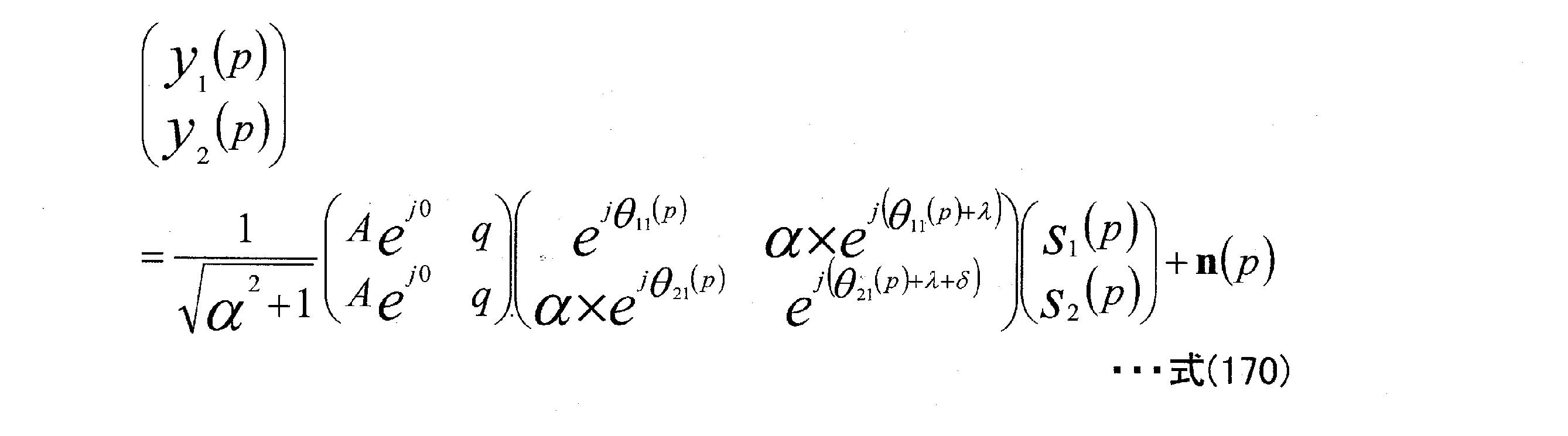

このとき、受信信号点と受信候補信号点とのユークリッド距離の最小値dmin
2がゼロと
なるqが2つ存在する。
式(171)においてs1(p)が存在しない:
At this time, there are two qs in which the minimum value d min 2 of the Euclidean distance between the received signal point and the received candidate signal point is zero.
S 1 (p) does not exist in equation (171):

式(171)においてs2(p)が存在しない: S 2 (p) does not exist in equation (171):

時間周期Nのプリコーディングホッピング方法において、式(169)を参考にし、N種類のプリコーディング行列F[i]を以下のようにあらわす。 In the precoding hopping method of the time period N, N kinds of precoding matrices F [i] are expressed as follows with reference to the equation (169).

ここで、αおよびδは時間的に変化しないものとする。このとき、式(34), (35)に基づき、以下のようなプリコーディングホッピングのプリコーディング行列の設計条件を与える。 Here, it is assumed that α and δ do not change with time. At this time, based on Eqs. (34) and (35), the following precoding matrix design conditions for precoding hopping are given.


(例#7)
式(174)のプリコーディング行列のα=1.0とする。そして、時間周期N=16とし、
<条件#12>, <条件#14>, <条件#15>を満たすために、次式のような時間周期N=8のプリコーディングホッピング方法におけるプリコーディング行列を与える。
(Example # 7)
Let α = 1.0 of the precoding matrix in equation (174). Then, set the time cycle N = 16
In order to satisfy <
i=0,1,…,7のとき: When i = 0,1,…, 7:

i=8,9,…,15のとき: When i = 8,9,…,15:

また、式(177)、式(178)と異なるプリコーディング行列として、以下のように与えることができる。
i=0,1,…,7のとき:
Further, it can be given as a precoding matrix different from the equations (177) and (178) as follows.
When i = 0,1,…, 7:

i=8,9,…,15のとき: When i = 8,9,…,15:

したがって、s1, s2の受信劣悪点は図33(a)(b)のようになる。
(図33において、横軸は実軸、縦軸は虚軸となる。)また、式(177)、式(178)および式(179)、式(180)のかわりに以下のようにプリコーディング行列を与えても良い。
Therefore, the reception inferior points of s 1 and s 2 are as shown in FIGS. 33 (a) and 33 (b).
(In FIG. 33, the horizontal axis is the real axis and the vertical axis is the imaginary axis.) Also, instead of the equation (177), the equation (178), the equation (179), and the equation (180), the precoding is as follows. You may give a matrix.
i=0,1,…,7のとき: When i = 0,1,…, 7:

i=8,9,…,15のとき: When i = 8,9,…,15:

または、
i=0,1,…,7のとき:
or,
When i = 0,1,…, 7:

i=8,9,…,15のとき: When i = 8,9,…,15:

(また、式(177)~(184)において、7π/8を-7π/8としてもよい。)
次に、<条件#12>とは異なる、qの位相のみが異なる同一のLOS環境において、Γ個の端末に対し、可能な限り公平なデータの受信品質を与えるための条件として、以下を与える。
<条件#16>
時間周期Nスロットのプリコーディングホッピング方法を用いた場合、
(Also, in equations (177) to (184), 7π / 8 may be -7π / 8).
Next, in the same LOS environment where only the phase of q is different, which is different from <
<
When using the precoding hopping method of the time cycle N slot,

の条件を付加し、また、時間周期内のNにおいて、s1の受信劣悪点を位相とs2の受信劣
悪点を位相に対し、一様分布となるように配置する。
そこで、<条件#14>, <条件#15>, <条件#16>に基づくプリコーディングホッピング方法におけるプリコーディング行列の例を説明する。式(174)のプリコーディング行列のα=1.0とする。
(例#8)
時間周期N=8とし、次式のような時間周期N=8のプリコーディングホッピング方法におけるプリコーディング行列を与える。
The condition of is added, and the reception inferior points of s 1 are arranged so as to have a uniform distribution with respect to the phase and the reception inferior points of s 2 are arranged at N in the time cycle.
Therefore, an example of the precoding matrix in the precoding hopping method based on <
(Example # 8)
Let the time period N = 8, and give the precoding matrix in the precoding hopping method with the time period N = 8 as shown in the following equation.

ただし、i=0,1,…,7である。
また、式(186)と異なるプリコーディング行列として、以下のように与えることが
できる(i=0,1,…,7)(λ、θ11[i]は時間的に変化しないものとする(変化してもよい
)。)。
However, i = 0,1, ..., 7.
Further, as a precoding matrix different from the equation (186), it can be given as follows (i = 0,1, ..., 7) (λ, θ 11 [i] does not change with time (i). May change).).

したがって、s1, s2の受信劣悪点は図34のようになる。また、式(186)、式(187)のかわりに以下のようにプリコーディング行列を与えても良い(i=0,1,…,7)(λ、θ11[i]は時間的に変化しないものとする(変化してもよい)。)。 Therefore, the reception inferior points of s 1 and s 2 are as shown in FIG. 34. Further, instead of the equations (186) and (187), a precoding matrix may be given as follows (i = 0,1, ..., 7) (λ, θ 11 [i] changes with time. Not (may change).

または、 or,

(また、式(186)~式(189)において、7π/8を-7π/8としてもよい。)
次に、式(174)のプリコーディング行列において、α≠1とし、受信劣悪点同士の
複素平面における距離の点を考慮した(例#7), (例#8)と異なるプリコーディングホッピング方法について考える。
(Also, in equations (186) to (189), 7π / 8 may be changed to -7π / 8.)
Next, in the precoding matrix of Eq. (174), α ≠ 1, and the precoding hopping method different from that of (Example # 7) and (Example # 8) in which the point of the distance between the reception inferior points in the complex plane is taken into consideration. think.
ここでは、式(174)の時間周期Nのプリコーディングホッピング方法を扱っている
が、このとき、<条件#14>により、Γ個の端末すべてにおいて、時間周期内のNにお
いて、s1の受信劣悪点をとるスロットは1スロット以下となる。したがって、N-1スロット以上s1(p)で送信したビットの対数尤度比を得ることができる。同様に、<条件#15>
により、Γ個の端末すべてにおいて、時間周期内のNにおいて、s2の受信劣悪点をとるス
ロットは1スロット以下となる。したがって、N-1スロット以上s2(p)で送信したビットの
対数尤度比を得ることができる。
Here, the precoding hopping method of the time cycle N of the equation (174) is dealt with. At this time, according to <
As a result, in all Γ terminals, the number of slots that take the reception poor point of s 2 is 1 slot or less in N within the time cycle. Therefore, the log-likelihood ratio of the bits transmitted in s 2 (p) over the N-1 slot can be obtained.
したがって、時間周期Nは大きい値をしたほうが、対数尤度比を得ることができるスロ
ット数が大きくなることがわかる。
ところで、実際のチャネルモデルでは、散乱波成分の影響をうけるため、時間周期Nが
固定の場合、受信劣悪点の複素平面上の最小距離は可能な限り大きい方が、データの受信品質が向上する可能性があると考えられる。したがって、(例#7), (例#8)において、α≠1とし、(例#7), (例#8)を改良したプリコーディングホッピング方法に
ついて考える。まず、理解が容易となる、(例#8)を改良したプリコーディング方法に
ついて述べる。
(例#9)
式(186)から、(例#7)を改良した時間周期N=8のプリコーディングホッピング
方法におけるプリコーディング行列を次式で与える。
Therefore, it can be seen that the larger the time period N is, the larger the number of slots from which the log-likelihood ratio can be obtained.
By the way, in the actual channel model, since it is affected by the scattered wave component, when the time period N is fixed, the data reception quality is improved when the minimum distance on the complex plane of the reception inferior point is as large as possible. It seems possible. Therefore, in (Example # 7) and (Example # 8), α ≠ 1, and consider an improved precoding hopping method in (Example # 7) and (Example # 8). First, an improved precoding method (Example # 8) that is easy to understand will be described.
(Example # 9)
From equation (186), the precoding matrix in the precoding hopping method with a time period N = 8 improved from (Example # 7) is given by the following equation.

ただし、i=0,1,…,7である。また、式(190)と異なるプリコーディング行列として、以下のように与えることができる(i=0,1,…,7)(λ、θ11[i]は時間的に変化しない
ものとする(変化してもよい)。)。
However, i = 0,1, ..., 7. Further, as a precoding matrix different from Eq. (190), it can be given as follows (i = 0,1, ..., 7) (λ, θ 11 [i] does not change with time (it is assumed). May change).).

または、 or,

または、 or,

または、 or,
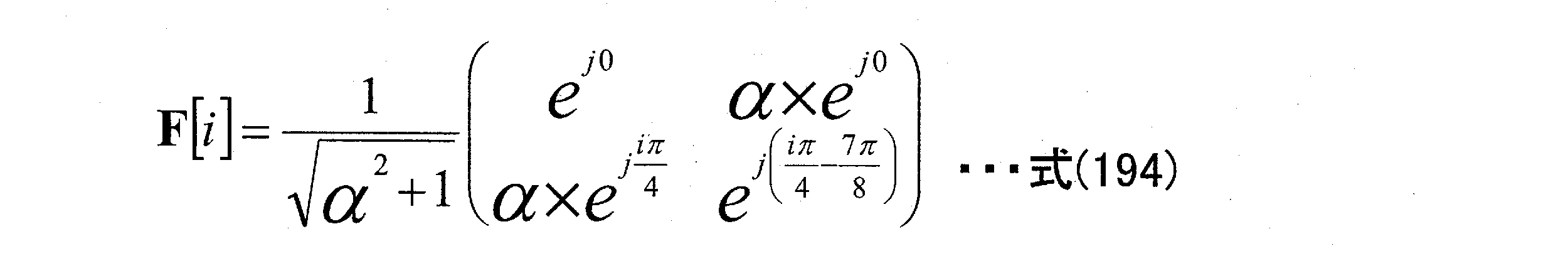
または、 or,

または、 or,

または、 or,

したがって、s1, s2の受信劣悪点はα<1.0のとき図35(a)、α>1.0のとき図35(b)のようにあらわされる。
(i)α<1.0のとき
α<1.0のとき、受信劣悪点の複素平面における最小距離は、受信劣悪点#1と#2の距離(d#1,#2)および、受信劣悪点#1と#3の距離(d#1,#3)に着目すると、min{d#1,
#2, d#1,#3}とあらわされる。このとき、αとd#1,#2およびd#1,#3の関係を図36に示す。そし
て、min{d#1,#2, d#1,#3}を最も大きくするαは
Therefore, the poor reception points of s 1 and s 2 are shown in FIG. 35 (a) when α <1.0 and in FIG. 35 (b) when α> 1.0.
(i) When α <1.0 When α <1.0, the minimum distance of the reception inferior point in the complex plane is the distance between the reception
It is expressed as # 2 , d # 1, # 3 }. At this time, the relationship between α and d # 1, # 2 and d # 1, # 3 is shown in FIG. And α that maximizes min {d # 1, # 2 , d # 1, # 3 } is

となる。このときのmin{d#1,#2, d#1,#3}は Will be. At this time, min {d # 1, # 2 , d # 1, # 3 } is

となる。したがって、式(190)~式(197)においてαを式(198)で与えるプリコーディング方法が有効となる。ただし、αの値を式(198)と設定することは、良好なデータの受信品質を得るための一つの適切な方法である。しかし、式(198)に近いような値をとるようにαを設定しても、同様に、良好なデータの受信品質を得ることができる可能性がある。したがって、αの設定値は、式(198)に限ったものではない。 Will be. Therefore, in the equations (190) to (197), the precoding method in which α is given by the equation (198) is effective. However, setting the value of α to the equation (198) is one appropriate method for obtaining good data reception quality. However, even if α is set so as to take a value close to that of the equation (198), there is a possibility that good data reception quality can be obtained in the same manner. Therefore, the set value of α is not limited to the equation (198).
(ii)α>1.0のとき
α>1.0のとき、受信劣悪点の複素平面における最小距離は、受信劣悪点#4と#5の距離(d#4,#5)および、受信劣悪点#4と#6の距離(d#4,#6)に着目すると、min{d#4,
#5, d#4,#6}とあらわされる。このとき、αとd#4,#5およびd#4,#6の関係を図37に示す。そし
て、min{d#4,#5, d#4,#6}を最も大きくするαは
(ii) When α> 1.0 When α> 1.0, the minimum distance of the reception inferior point in the complex plane is the distance between the reception
It is expressed as # 5 , d # 4, # 6 }. At this time, the relationship between α and d # 4, # 5 and d # 4, # 6 is shown in FIG. 37. And α that maximizes min {d # 4, # 5 , d # 4, # 6 } is

となる。このときのmin{d#4,#5, d#4,#6}は Will be. At this time, min {d # 4, # 5 , d # 4, # 6 } is

となる。したがって、式(190)~式(197)においてαを式(200)で与えるプリコーディング方法が有効となる。ただし、αの値を式(200)と設定することは、良好なデータの受信品質を得るための一つの適切な方法である。しかし、式(200)に
近いような値をとるようにαを設定しても、同様に、良好なデータの受信品質を得ることができる可能性がある。したがって、αの設定値は、式(200)に限ったものではない。
(例#10)
(例#9)の検討から(例#7)を改良した時間周期N=16のプリコーディングホッピング方法におけるプリコーディング行列は次式で与えることができる(λ、θ11[i]は時間
的に変化しないものとする(変化してもよい)。)。
Will be. Therefore, in the equations (190) to (197), the precoding method in which α is given by the equation (200) is effective. However, setting the value of α to the equation (200) is one appropriate method for obtaining good data reception quality. However, even if α is set so as to take a value close to the equation (200), there is a possibility that good data reception quality can be obtained in the same manner. Therefore, the set value of α is not limited to the equation (200).
(Example # 10)
The precoding matrix in the precoding hopping method with a time period N = 16 which is an improvement of (Example # 7) from the examination of (Example # 9) can be given by the following equation (λ, θ 11 [i] is temporally. It shall not change (may change).
i=0,1,…,7のとき: When i = 0,1,…, 7:

i=8,9,…,15のとき: When i = 8,9,…,15:

または、
i=0,1,…,7のとき:
or,
When i = 0,1,…, 7:

i=8,9,…,15のとき: When i = 8,9,…,15:

または、
i=0,1,…,7のとき:
or,
When i = 0,1,…, 7:

i=8,9,…,15のとき: When i = 8,9,…,15:

または、
i=0,1,…,7のとき:
or,
When i = 0,1,…, 7:
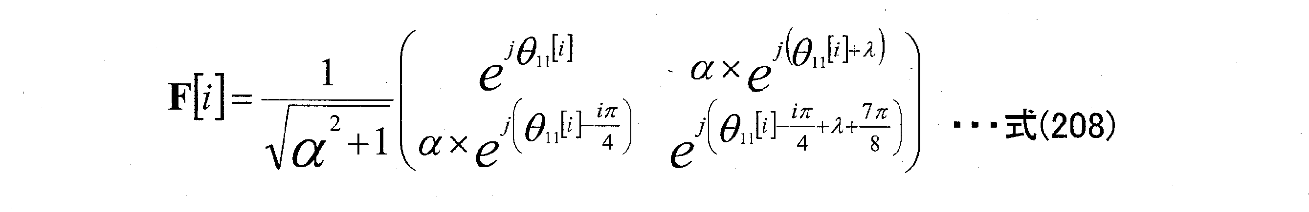
i=8,9,…,15のとき: When i = 8,9,…,15:

または、
i=0,1,…,7のとき:
or,
When i = 0,1,…, 7:

i=8,9,…,15のとき: When i = 8,9,…,15:

または、
i=0,1,…,7のとき:
or,
When i = 0,1,…, 7:

i=8,9,…,15のとき: When i = 8,9,…,15:

または、
i=0,1,…,7のとき:
or,
When i = 0,1,…, 7:

i=8,9,…,15のとき: When i = 8,9,…,15:

または、
i=0,1,…,7のとき:
or,
When i = 0,1,…, 7:

i=8,9,…,15のとき: When i = 8,9,…,15:

ただし、αは式(198)または式(200)となると良好なデータの受信品質を得るのに適している。このとき、s1の受信劣悪点はα<1.0のとき図38(a)(b)、α>1.0のとき図39(a)(b)のようにあらわされる。 However, α is suitable for obtaining good data reception quality when it becomes the formula (198) or the formula (200). At this time, the poor reception of s 1 is shown in FIGS. 38 (a) (b) when α <1.0 and in FIGS. 39 (a) (b) when α> 1.0.
本実施の形態では、時間周期Nのプリコーディングホッピング方法のためのN個の異なるプリコーディング行列の構成方法について説明した。このとき、N個の異なるプリコーデ
ィング行列として、F[0]、F[1]、F[2]、・・・、F[N-2]、F[N-1]を用意することになるが、本実施の形態は、シングルキャリア伝送方式のときを例に説明しているため時間軸(または、周波数軸)方向にF[0]、F[1]、F[2]、・・・、F[N-2]、F[N-1]の順に並べる場合について説明したが、必ずしもこれに限ったものではなく、本実施の形態で生成したN個の
異なるプリコーディング行列F[0]、F[1]、F[2]、・・・、F[N-2]、F[N-1]をOFDM伝送方式等のマルチキャリア伝送方式に適用することもできる。この場合の適用方法については、実施の形態1と同様に、周波数軸、周波数―時間軸に対し、シンボルを配置することで、プリコーディングウェイトを変更することができる。なお、時間周期Nのプリコーディン
グホッピング方法として説明しているが、N個の異なるプリコーディング行列をランダム
に用いるようにしても同様の効果を得ることができる、つまり、必ずしも、規則的な周期を持つようにN個の異なるプリコーディング行列を用いる必要はない。
In this embodiment, a method of constructing N different precoding matrices for a precoding hopping method having a time period N has been described. At this time, F [0], F [1], F [2], ..., F [N-2], F [N-1] are prepared as N different precoding matrices. However, since this embodiment is described by taking the case of a single carrier transmission method as an example, F [0], F [1], F [2], ... , F [N-2], F [N-1] have been described in this order, but the present invention is not limited to this, and N different precoding matrices F [0] generated in the present embodiment have been described. , F [1], F [2], ..., F [N-2], F [N-1] can also be applied to a multi-carrier transmission method such as an OFDM transmission method. As for the application method in this case, the precoding weight can be changed by arranging the symbols on the frequency axis and the frequency-time axis as in the first embodiment. Although it is described as a precoding hopping method having a time period N, the same effect can be obtained by randomly using N different precoding matrices, that is, a regular period is not always used. You don't have to use N different precoding matrices to have.
<条件#10>から<条件#16>に基づき、例#5から例#10を示したが、プリコーディング行列の切り替え周期を長くするために、例えば、例#5から例#10から複数の例を選び、その選択した例で示したプリコーディング行列を用いて長い周期のプリコーディング行列切り替え方法を実現してもよい。例えば、例#7で示したプリコーディング行列と例#10で示したプリコーディング行列を用いて、長い周期のプリコーディング行列切り替え方法を実現するということになる。この場合、<条件#10>から<条件#16>に必ずしもしたがうとはかぎらない。(<条件#10>の式(158)、<条件#11>の式(159)、<条件#13>の式(164)、<条件#14>の式(175)、<条件#15>の式(176)において、「すべてのx、すべてのy」としているところを「存在することのx、存在することのy」という条件が、良好な受信品質を与える上で重要となる、ということになる。)別の視点で考えた場合、周期N(Nは大きな自然数とする)のプリコーディング行列切り替え方法において、例#5から例#10のいずれかのプリコーディング行列が含まれると良好な受信品質を与える可能性が高くなる。
(実施の形態7)
本実施の形態では、実施の形態1~6で説明した規則的にプリコーディング行列を切り替える送信方法で送信された変調信号を受信する受信装置の構成について説明する。
(Embodiment 7)
In the present embodiment, the configuration of the receiving device for receiving the modulated signal transmitted by the transmission method for regularly switching the precoding matrix described in the first to sixth embodiments will be described.
実施の形態1では、規則的にプリコーディング行列を切り替える送信方法を用いて変調信号を送信する送信装置が、プリコーディング行列に関する情報を送信し、受信装置が、その情報に基づき、送信フレームに用いられている規則的なプリコーディング行列切り替え情報を得、プリコーディングの復号、および、検波を行い、送信ビットの対数尤度比を得、その後、誤り訂正復号を行う方法について説明した。 In the first embodiment, a transmitting device that transmits a modulated signal using a transmission method that periodically switches the precoding matrix transmits information about the precoding matrix, and a receiving device uses the information for a transmission frame based on the information. The method of obtaining the regular precoding matrix switching information, decoding the precoding, performing detection, obtaining the log-possibility ratio of the transmission bit, and then performing error correction decoding has been described.
本実施の形態では、上記とは異なる受信装置の構成、および、プリコーディング行列の切り替え方法について説明する。
図40は、本実施の形態における送信装置の構成の一例を示しており、図3と同様に動作するものについては同一符号を付した。符号化器群(4002)は、送信ビット(4001)を入力とする。このとき、符号化器群(4002)は、実施の形態1で説明したように、誤り訂正符号の符号化部を複数個保持しており、フレーム構成信号313に基づき、例えば、1つの符号化、2つの符号化器、4つの符号化器のいずれかの数の符号化器が動作することになる。
In this embodiment, a configuration of a receiving device different from the above and a method of switching the precoding matrix will be described.
FIG. 40 shows an example of the configuration of the transmission device according to the present embodiment, and the same reference numerals are given to those operating in the same manner as in FIG. The encoder group (4002) receives a transmission bit (4001) as an input. At this time, as described in the first embodiment, the encoder group (4002) holds a plurality of coding units of the error correction code, and based on the
1つの符号化器が動作する場合、送信ビット(4001)は、符号化が行われ、符号化後の送信ビットが得られ、この符号化後の送信ビットを2系統に分配し、分配されたビット(4003A)および分配されたビット(4003B)を符号化器群(4002)は出力する。 When one encoder operates, the transmit bit (4001) is encoded to obtain the encoded transmit bit, and the encoded transmit bit is distributed and distributed to the two systems. The encoder group (4002) outputs the bits (4003A) and the distributed bits (4003B).
2つの符号化器が動作する場合、送信ビット(4001)を2つに分割して(分割ビットA、Bと名付ける)、第1の符号化器は、分割ビットAを入力とし、符号化を行い、符号化後のビットを分配されたビット(4003A)として出力する。第2の符号化器は、分割ビットBを入力とし、符号化を行い、符号化後のビットを分配されたビット(4003B)として出力する。 When two encoders operate, the transmission bit (4001) is divided into two (named division bits A and B), and the first encoder receives the division bit A as an input and encodes. Then, the encoded bits are output as distributed bits (4003A). The second encoder takes the divided bit B as an input, performs encoding, and outputs the encoded bit as a distributed bit (4003B).
4つの符号化器が動作する場合、送信ビット(4001)を4つに分割して(分割ビットA、B、C、Dと名付ける)、第1の符号化器は、分割ビットAを入力とし、符号化を行い、符号化後のビットAを出力する。第2の符号化器は、分割ビットBを入力とし、符号化を行い、符号化後のビットBを出力する。第3の符号化器は、分割ビットCを入力とし、符号化を行い、符号化後のビットCを出力する。第4の符号化器は、分割ビットDを入力とし、符号化を行い、符号化後のビットDを出力する。そして、符号化後のビットA、B、C、Dを分配されたビット(4003A)、分配されたビット(4003B)に分割する。 When the four encoders operate, the transmission bit (4001) is divided into four (named the division bits A, B, C, and D), and the first encoder receives the division bit A as an input. , Encoding is performed, and the encoded bit A is output. The second encoder takes the divided bit B as an input, performs coding, and outputs the encoded bit B. The third encoder takes the divided bit C as an input, performs coding, and outputs the coded bit C. The fourth encoder takes the divided bit D as an input, performs coding, and outputs the coded bit D. Then, the encoded bits A, B, C, and D are divided into distributed bits (4003A) and distributed bits (4003B).
送信装置は、一例として、以下の表1(表1Aおよび表1B)のような送信方法をサポートすることになる。 As an example, the transmission device will support the transmission methods as shown in Table 1 (Table 1A and Table 1B) below.


表1に示すように、送信信号数(送信アンテナ数)としては、1ストリームの信号の送信と2ストリームの信号の送信をサポートする。また、変調方式はQPSK、16QAM、64QAM、256QAM、1024QAMをサポートする。特に、送信信号数が2のとき、ストリーム#1とストリーム#2は別々に変調方式を設定することが可能であり、
例えば、表1において、「#1: 256QAM, #2: 1024QAM」は「ストリーム#1の変調方式
は256QAM、ストリーム#2の変調方式は1024QAM」ということを示している(他についても同様に表現している)。誤り訂正符号化方式としては、A、B、Cの3種類をサポートしているものとする。このとき、A、B、Cはいずれも異なる符号であってもよいし、A、B、Cは異なる符号化率であってもよいし、A、B、Cは異なるブロックサイズの符号化方法であってもよい。
As shown in Table 1, as the number of transmission signals (number of transmission antennas), transmission of one stream of signals and transmission of two streams of signals are supported. The modulation scheme also supports QPSK, 16QAM, 64QAM, 256QAM and 1024QAM. In particular, when the number of transmission signals is 2, the modulation method can be set separately for
For example, in Table 1, "# 1: 256QAM, # 2: 1024QAM" indicates that "the modulation method of
表1の送信情報は、「送信信号数」「変調方式」「符号化器数」「誤り訂正符号化方法」を定めた各モードに対し、各送信情報を割り当てる。したがって、例えば、「送信信号数:2」「変調方式:#1:1024QAM、#2:1024QAM」「符号化器数:4」「誤り訂正符号化方法:C」の場合、送信情報を01001101と設定する。そして、送信装置は、フレームにおいて、送信情報、および、送信データを伝送する。そして、送信データを伝送する際、特に、「送信信号数」が2のとき、表1にしたがって、「プリコーディング行列切り替え方法」を用いることになる。表1において、「プリコーディング行列切り替え方法」としては、D,E,F,G,Hの5種類を用意しておき、この5種類のいずれかを、表1にしたがって、設定することになる。このとき、異なる5種類の実現方法としては、
・プリコーディング行列が異なる5種類を用意し、実現する。
・異なる5種類の周期、例えば、Dの周期を4、Eの周期を8、・・・、とすることで、実現する。
・異なるプリコーディング行列、異なる周期の両者を併用することで、実現する。
等が考えられる。
For the transmission information in Table 1, each transmission information is assigned to each mode in which the "number of transmission signals", "modulation method", "number of encoders", and "error correction coding method" are defined. Therefore, for example, in the case of "number of transmission signals: 2", "modulation method: # 1: 1024QAM, # 2: 1024QAM", "number of encoders: 4", and "error correction coding method: C", the transmission information is set to 01001101. Set. Then, the transmission device transmits the transmission information and the transmission data in the frame. Then, when transmitting the transmission data, particularly when the "number of transmission signals" is 2, the "precoding matrix switching method" is used according to Table 1. In Table 1, five types of "precoding matrix switching method", D, E, F, G, and H, are prepared, and one of these five types is set according to Table 1. .. At this time, as five different realization methods,
・ Prepare and realize 5 types with different precoding matrices.
-It is realized by setting five different types of cycles, for example, the period of D to 4, the period of E to 8, and so on.
-It is realized by using both different precoding matrices and different periods together.
Etc. are conceivable.
図41は、図40の送信装置が送信する変調信号のフレーム構成の一例を示しており、送信装置は、2つの変調信号z1(t)とz2(t)を送信するようなモードの設定、および、1つの変調信号を送信するモードの両者の設定が可能であるものとする。 FIG. 41 shows an example of a frame configuration of a modulated signal transmitted by the transmitting device of FIG. 40, and the transmitting device sets a mode for transmitting two modulated signals z1 (t) and z2 (t). It is assumed that both the mode for transmitting one modulated signal and the mode for transmitting one modulated signal can be set.
図41において、シンボル(4100)は、表1に示されている「送信情報」を伝送するためのシンボルである。シンボル(4101_1、および、4101_2)は、チャネル推定用のリファレンス(パイロット)シンボルである。シンボル(4102_1、4103_1)は、変調信号z1(t)で送信するデータ伝送用のシンボル、シンボル(4102_2、4103_2)は、変調信号z2(t)で送信するデータ伝送用のシンボルであり、シンボル(4102_1)およびシンボル(4102_2)は同一時刻に同一(共通)周波数を用いて伝送され、また、シンボル(4103_1)およびシンボル(4103_2)は同一時刻に同一(共通)周波数を用いて伝送される。そして、シンボル(4102_1、4103_1)、および、シンボル(4102_2、4103_2)は、実施の形態1~4、および、実施の形態6で説明した規則的にプリコーディング行列を切り替える方式を用いたときのプリコーディング行列演算後のシンボルとなる(したがって、実施の形態1で説明したように、ストリームs1(t)、s2(t)の構成は、図6のとおりである。)
さらに、図41において、シンボル(4104)は、表1に示されている「送信情報」を伝送するためのシンボルである。シンボル(4105)は、チャネル推定用のリファレンス(パイロット)シンボルである。シンボル(4106、4107)は、変調信号z1(t)で送信するデータ伝送用のシンボルであり、このとき、変調信号z1(t)で送信するデータ伝送用のシンボルは、送信信号数が1なので、プリコーディングが行われていないことになる。
In FIG. 41, the symbol (4100) is a symbol for transmitting the “transmission information” shown in Table 1. The symbols (4101-1 and 4101_2) are reference (pilot) symbols for channel estimation. The symbol (4102_1, 4103_1) is a symbol for data transmission transmitted by the modulation signal z1 (t), and the symbol (4102_1, 4103_1) is a symbol for data transmission transmitted by the modulation signal z2 (t). 4102_1) and the symbol (4102_2) are transmitted at the same time using the same (common) frequency, and the symbol (4103_1) and the symbol (4103_1) are transmitted using the same (common) frequency at the same time. The symbols (4102_1, 4103_1) and the symbols (4102_1, 4103_1) are pre-programmed when the method of regularly switching the precoding matrix described in the first to fourth embodiments and the sixth embodiment is used. It becomes a symbol after the coding matrix operation (hence, as described in the first embodiment, the configuration of the streams s1 (t) and s2 (t) is as shown in FIG. 6).
Further, in FIG. 41, the symbol (4104) is a symbol for transmitting the "transmission information" shown in Table 1. Symbol (4105) is a reference (pilot) symbol for channel estimation. The symbol (4106, 4107) is a symbol for data transmission transmitted by the modulated signal z1 (t), and at this time, the symbol for data transmission transmitted by the modulated signal z1 (t) has one transmission signal. , Precoding is not done.
よって、図40の送信装置は、図41のフレーム構成、および、表1にしたがった変調信号を生成し、送信することになる。図40において、フレーム構成信号313は、表1に基づき設定した「送信信号数」「変調方式」「符号化器数」「誤り訂正符号化方法」に
関する情報を含んでいることになる。そして、符号化部(4002)、マッピング部306A,B、重み付け合成部308A,B、は、フレーム構成信号を入力とし、表1に基づき設定した「送信信号数」「変調方式」「符号化器数」「誤り訂正符号化方法」に基づく動作を行うことになる。また、設定した「送信信号数」「変調方式」「符号化器数」「誤り訂正符号化方法」に相当する「送信情報」についても受信装置に送信することになる。
Therefore, the transmitting device of FIG. 40 generates and transmits the modulated signal according to the frame configuration of FIG. 41 and Table 1. In FIG. 40, the
受信装置の構成は、実施の形態1と同様図7であらわすことができる。実施の形態1と異なる点は、表1の情報を、送受信装置が予め共有しているため、送信装置が、規則的に切り替えるプリコーディング行列の情報を送信しなくても、「送信信号数」「変調方式」「符号化器数」「誤り訂正符号化方法」に相当する「送信情報」を送信装置が送信し、受信装置がこの情報を得ることで、表1から、規則的に切り替えるプリコーディング行列の情報を得ることができる、という点である。したがって、図7の受信装置は、制御情報復号部709が、図40の送信装置が送信した「送信情報」を得ることで、表1に相当する情報から、規則的に切り替えるプリコーディング行列の情報を含む送信装置が通知した送信方法の情報に関する信号710を得ることができる。したがって、信号処理部711は、送信信号数2のとき、プリコーディング行列の切り替えパターンに基づく検波を行うことができ、受信対数尤度比を得ることができる。
The configuration of the receiving device can be represented by FIG. 7 as in the first embodiment. The difference from the first embodiment is that the information in Table 1 is shared in advance by the transmission / reception device, so that the transmission device does not need to transmit the information of the precoding matrix to be regularly switched, but the “number of transmission signals”. The transmitting device transmits "transmission information" corresponding to the "modulation method", "number of encoders", and "error correction coding method", and the receiving device obtains this information to periodically switch from Table 1 to the pre. The point is that information on the coding matrix can be obtained. Therefore, in the receiving device of FIG. 7, the control
なお、上述では、表1のように、「送信信号数」「変調方式」「符号化器数」「誤り訂正符号化方法」に対し、「送信情報」を設定し、これに対し、プリコーディング行列切り替え方法を設定しているが、必ずしも、「送信信号数」「変調方式」「符号化器数」「誤り訂正符号化方法」に対し、「送信情報」を設定しなくてもよく、例えば、表2のように、「送信信号数」「変調方式」に対し、「送信情報」を設定し、これに対し、プリコーディング行列切り替え方法を設定してもよい。 In the above, as shown in Table 1, "transmission information" is set for "number of transmission signals", "modulation method", "number of encoders", and "error correction coding method", and precoding is performed for this. Although the matrix switching method is set, it is not always necessary to set "transmission information" for "number of transmission signals", "modulation method", "number of encoders", and "error correction coding method", for example. , As shown in Table 2, "transmission information" may be set for "number of transmission signals" and "modulation method", and a precoding matrix switching method may be set for this.

ここで、「送信情報」、および、プリコーディング行列切り替え方法の設定方法は、表1や表2に限ったものではなく、プリコーディング行列切り替え方法は、「送信信号数」「変調方式」「符号化器数」「誤り訂正符号化方法」等の送信パラメータに基づいて切り替えるように予め規則が決められていれば(送信装置、受信装置で予め決められている規則が共有されていれば)、(つまり、プリコーディング行列切り替え方法を、送信パラメータのいずれか、(または、送信パラメータの複数で構成されたいずれか)によって、切り替えていれば)、送信装置は、プリコーディング行列切り替え方法に関する情報を伝送する必要がなく、受信装置は、送信パラメータの情報を判別することで、送信装置が用いたプリコーディング行列切り替え方法を判別することができるので、的確な復号、検波を行うことができる。なお、表1、表2では、送信変調信号数が2のとき、規則的にプリコーディング行列を切り替える送信方法を用いるものとしているが、送信変調信号数が2以上であれば、規則的にプリコーディング行列を切り替える送信方法を適用することができる。 Here, the setting method of the "transmission information" and the precoding matrix switching method is not limited to Table 1 and Table 2, and the precoding matrix switching method includes "number of transmission signals", "modulation method", and "code". If the rules are predetermined to switch based on the transmission parameters such as "number of converters" and "error correction coding method" (if the transmitters and receivers share the predetermined rules), (That is, if the precoding matrix switching method is switched by one of the transmission parameters (or one consisting of multiple transmission parameters)), the transmitter provides information about the precoding matrix switching method. Since it is not necessary to transmit and the receiving device can determine the precoding matrix switching method used by the transmitting device by discriminating the information of the transmission parameter, accurate decoding and detection can be performed. In Tables 1 and 2, when the number of transmission modulation signals is 2, the transmission method of regularly switching the precoding matrix is used. However, if the number of transmission modulation signals is 2 or more, the precoding matrix is regularly switched. A transmission method for switching the coding matrix can be applied.
したがって、送受信装置が、プリコーディング切り替え方法に関する情報を含む送信パラメータに関する表を共有していれば、送信装置が、プリコーディング切り替え方法に関する情報を送信せず、プリコーディング切り替え方法に関する情報を含まない制御情報を送信し、受信装置が、この制御情報を得ることで、プリコーディング切り替え方法を推定することができることになる。 Therefore, if the transmitter / receiver shares a table of transmit parameters that include information about the precoding switching method, the transmitter does not transmit information about the precoding switching method and does not include information about the precoding switching method. By transmitting the information and obtaining this control information, the receiving device can estimate the precoding switching method.
以上のように、本実施の形態では、送信装置が、規則的にプリコーディング行列を切り替える方法に関する直接の情報を送信せずに、受信装置が、送信装置が用いた「規則的にプリコーディング行列を切り替える方法」のプリコーディングに関する情報を推定する方法について、説明した。これにより、送信装置は、規則的にプリコーディング行列を切り替える方法に関する直接の情報を送信しないので、その分、データの伝送効率が向上するという効果を得ることができる。 As described above, in the present embodiment, the transmitting device does not transmit direct information on how to regularly switch the precoding matrix, and the receiving device uses the “regularly precoding matrix” used by the transmitting device. I explained how to estimate the information about precoding in "How to switch between". As a result, the transmitting device does not transmit direct information regarding the method of regularly switching the precoding matrix, so that the effect of improving the data transmission efficiency can be obtained.
なお、本実施の形態において、時間軸におけるプリコーディングウェイト変更するときの実施の形態を説明したが、実施の形態1で説明したように、OFDM伝送等のマルチキャリア伝送方式を用いたときでも本実施の形態は同様に実施することができる。 In the present embodiment, the embodiment when the precoding weight is changed on the time axis has been described, but as described in the first embodiment, even when a multi-carrier transmission method such as OFDM transmission is used. The embodiment can be implemented in the same manner.
また、特に、プリコーディング切り替え方法が、送信信号数のみによって変更されているとき、受信装置は、送信装置が送信する送信信号数の情報を得ることで、プリコーディング切り替え方法をしることができる。 Further, in particular, when the precoding switching method is changed only by the number of transmitted signals, the receiving device can perform the precoding switching method by obtaining information on the number of transmitted signals transmitted by the transmitting device. ..
本明細書において、送信装置を具備しているのは、例えば、放送局、基地局、アクセスポイント、端末、携帯電話(mobile phone)等の通信・放送機器であることが考えられ、このとき、受信装置を具備しているのは、テレビ、ラジオ、端末、パーソナルコンピュータ、携帯電話、アクセスポイント、基地局等の通信機器であることが考えられる。また、本発明における送信装置、受信装置は、通信機能を有している機器であって、その機器が、テレビ、ラジオ、パーソナルコンピュータ、携帯電話等のアプリケーションを実行するための装置に何らかのインターフェースを解して接続できるような形態であることも考えられる。
また、本実施の形態では、データシンボル以外のシンボル、例えば、パイロットシンボル(プリアンブル、ユニークワード、ポストアンブル、リファレンスシンボル等)、制御情報用のシンボルなどが、フレームにどのように配置されていてもよい。そして、ここでは、パイロットシンボル、制御情報用のシンボルと名付けているが、どのような名付け方を行ってもよく、機能自体が重要となっている。
In the present specification, it is considered that a transmission device is provided in, for example, a communication / broadcasting device such as a broadcasting station, a base station, an access point, a terminal, or a mobile phone (mobile phone). It is conceivable that the receiver is equipped with a communication device such as a television, a radio, a terminal, a personal computer, a mobile phone, an access point, and a base station. Further, the transmitting device and the receiving device in the present invention are devices having a communication function, and the device provides some kind of interface to a device for executing an application such as a television, a radio, a personal computer, and a mobile phone. It is also conceivable that the form can be solved and connected.
Further, in the present embodiment, no matter how symbols other than the data symbols, such as pilot symbols (preamble, unique word, postamble, reference symbol, etc.), symbols for control information, etc., are arranged in the frame. good. Here, the names are pilot symbols and symbols for control information, but any naming method may be used, and the function itself is important.
パイロットシンボルは、例えば、送受信機において、PSK変調を用いて変調した既知のシンボル(または、受信機が同期をとることによって、受信機は、送信機が送信したシンボルを知ることができてもよい。)であればよく、受信機は、このシンボルを用いて、周波数同期、時間同期、(各変調信号の)チャネル推定(CSI(Channel State Information)の推定)、信号の検出等を行うことになる。 The pilot symbol may be, for example, a known symbol modulated using PSK modulation in the transmitter / receiver (or by synchronizing the receiver, the receiver may be able to know the symbol transmitted by the transmitter. ), And the receiver uses this symbol to perform frequency synchronization, time synchronization, channel estimation (estimation of CSI (Channel State Information)) (estimation of CSI (Channel State Information)), signal detection, and the like. Become.
また、制御情報用のシンボルは、(アプリケーション等の)データ以外の通信を実現するための、通信相手に伝送する必要がある情報(例えば、通信に用いている変調方式・誤り訂正符号化方式・誤り訂正符号化方式の符号化率、上位レイヤーでの設定情報等)を伝送するためのシンボルである。 In addition, the symbol for control information is information that needs to be transmitted to the communication partner (for example, the modulation method / error correction coding method used for communication) in order to realize communication other than data (such as an application). It is a symbol for transmitting error correction coding method coding rate, setting information in the upper layer, etc.).
なお、本発明は上記実施の形態1~5に限定されず、種々変更して実施することが可能である。例えば、上記実施の形態では、通信装置として行う場合について説明しているが、これに限られるものではなく、この通信方法をソフトウェアとして行うことも可能であ
る。
The present invention is not limited to the
また、上記では、2つの変調信号を2つのアンテナから送信する方法におけるプリコーディング切り替え方法について説明したが、これに限ったものではなく、4つのマッピング後の信号に対し、プリコーディングを行い、4つの変調信号を生成し、4つのアンテナから送信する方法、つまり、N個のマッピング後の信号に対し、プリコーディングを行い、N個の変調信号を生成し、N個のアンテナから送信する方法においても同様にプリコーディングウェイト(行列)を変更する、プリコーディング切り替え方法としても同様に実施することができる。 Further, in the above, the precoding switching method in the method of transmitting two modulated signals from two antennas has been described, but the present invention is not limited to this, and precoding is performed on the four mapped signals, and 4 In the method of generating one modulated signal and transmitting it from four antennas, that is, the method of precoding the N mapped signals, generating N modulated signals, and transmitting them from N antennas. Similarly, the precoding weight (matrix) can be changed as well as the precoding switching method.
本明細書では、「プリコーディング」「プリコーディングウェイト」等の用語を用いているが、呼び方自体は、どのようなものでもよく、本発明では、その信号処理自体が重要となる。 In the present specification, terms such as "precoding" and "precoding weight" are used, but the term itself may be any, and in the present invention, the signal processing itself is important.
ストリームs1(t)、s2(t)により、異なるデータを伝送してもよいし、同一のデータを伝送してもよい。
送信装置の送信アンテナ、受信装置の受信アンテナ、共に、図面で記載されている1つのアンテナは、複数のアンテナにより構成されていても良い。
Different data may be transmitted or the same data may be transmitted depending on the streams s1 (t) and s2 (t).
Both the transmitting antenna of the transmitting device and the receiving antenna of the receiving device, one antenna described in the drawings may be composed of a plurality of antennas.
なお、例えば、上記通信方法を実行するプログラムを予めROM(Read Only
Memory)に格納しておき、そのプログラムをCPU(Central Processor Unit)によって動作させるようにしても良い。
In addition, for example, a program for executing the above communication method is stored in ROM (Read Only) in advance.
It may be stored in Memory) and the program may be operated by a CPU (Central Processor Unit).
また、上記通信方法を実行するプログラムをコンピュータで読み取り可能な記憶媒体に格納し、記憶媒体に格納されたプログラムをコンピュータのRAM(Random Access Memory)に記録して、コンピュータをそのプログラムにしたがって動作させるようにしても良い。 Further, a program for executing the above communication method is stored in a storage medium readable by a computer, the program stored in the storage medium is recorded in a RAM (Random Access Memory) of the computer, and the computer is operated according to the program. You may do so.
そして、上記の各実施の形態などの各構成は、典型的には集積回路であるLSI(Large Scale Integration)として実現されてもよい。これらは、個別に1チップ化されてもよいし、各実施の形態の全ての構成または一部の構成を含むように1チップ化されてもよい。 ここでは、LSIとしたが、集積度の違いにより、IC(Integrated Circuit)、システムLSI、スーパーLSI、ウルトラLSIと呼称されることもある。また、集積回路化の手法はLSIに限られるものではなく、専用回路または汎用プロセッサで実現しても良い。LSI製造後に、プログラムすることが可能なFPGA(Field Programmable Gate Array)や、LSI内部の回路セルの接続や設定を再構成可能なリコンフィギュラブル・プロセッサを利用しても良い。 Then, each configuration such as each of the above-described embodiments may be realized as an LSI (Large Scale Integration), which is typically an integrated circuit. These may be individually integrated into one chip, or may be integrated into one chip so as to include all or a part of the configurations of each embodiment. Although it is referred to as an LSI here, it may be referred to as an IC (Integrated Circuit), a system LSI, a super LSI, or an ultra LSI depending on the degree of integration. Further, the method of making an integrated circuit is not limited to the LSI, and may be realized by a dedicated circuit or a general-purpose processor. An FPGA (Field Programmable Gate Array) that can be programmed after the LSI is manufactured, or a reconfigurable processor that can reconfigure the connection and settings of the circuit cells inside the LSI may be used.
さらに、半導体技術の進歩又は派生する別技術によりLSIに置き換わる集積回路化の技術が登場すれば、当然、その技術を用いて機能ブロックの集積化を行っても良い。バイオ技術の適応等が可能性としてあり得る。 Further, if an integrated circuit technology that replaces an LSI appears due to advances in semiconductor technology or another technology derived from it, it is naturally possible to integrate functional blocks using that technology. There is a possibility of adaptation of biotechnology.
(実施の形態8)
本実施の形態では、実施の形態1~4、実施の形態6で説明したプリコーディングウェイトを規則的に切り替える方法の応用例について、ここでは説明する。
(Embodiment 8)
In the present embodiment, an application example of the method of regularly switching the precoding weights described in the first to fourth embodiments and the sixth embodiment will be described here.
図6は、本実施の形態における重み付け方法(プリコーディング(Precoding)方法)に関連する図であり、重み付け合成部600は、図3の重み付け合成部308A
と308Bの両者を統合した重み付け合成部である。図6に示すように、ストリームs1(t)およびストリームs2(t)は、図3のベースバンド信号307Aおよび307Bに相当する、つまり、QPSK、16QAM、64QAMなどの変調方式のマッピングにしたがったベースバンド信号同相I、直交Q成分となる。そして、図6のフレーム構成のようにストリームs1(t)は、シンボル番号uの信号をs1(u)、シンボル番号u+1の信号をs1(u+1)、・・・とあらわす。同様に、ストリームs2(t)は、シンボル番号uの信号をs2(u)、シンボル番号u+1の信号をs2(u+1)、・・・とあらわす。そして、重み付け合成部600は、図3におけるベースバンド信号307A(s1(t))および307B(s2(t))、重み付け情報に関する情報315を入力とし、重み付け情報に関する情報315にしたがった重み付け方法を施し、図3の重み付け合成後の信号309A(z1(t))、309B(z2(t))を出力する。
FIG. 6 is a diagram related to the weighting method (precoding method) in the present embodiment, and the
It is a weighting synthesis unit that integrates both 308B and 308B. As shown in FIG. 6, the streams s1 (t) and streams s2 (t) correspond to the baseband signals 307A and 307B of FIG. 3, that is, the base according to the mapping of the modulation scheme such as QPSK, 16QAM, 64QAM. Band signal common phase I and quadrature Q component. Then, as in the frame configuration of FIG. 6, the stream s1 (t) represents the signal of the symbol number u as s1 (u), the signal of the symbol number u + 1 as s1 (u + 1), and so on. Similarly, the stream s2 (t) represents the signal with the symbol number u as s2 (u), the signal with the symbol number u + 1 as s2 (u + 1), and so on. Then, the
このとき、例えば、実施の形態6における例8の周期N=8のプリコーディング行列切り
替え方法を用いた場合、z1(t)、z2(t)は以下のようにあらわされる。
シンボル番号8iのとき(iは0以上の整数とする):
At this time, for example, when the precoding matrix switching method of the period N = 8 of Example 8 in the sixth embodiment is used, z1 (t) and z2 (t) are represented as follows.
When the symbol number is 8i (i is an integer of 0 or more):

ただし、jは虚数単位、k=0。
シンボル番号8i+1のとき:
However, j is an imaginary unit, k = 0.
When the symbol number is 8i + 1:

ただし、k=1。
シンボル番号8i+2のとき:
However, k = 1.
When the symbol number is 8i + 2:

ただし、k=2。
シンボル番号8i+3のとき:
However, k = 2.
When the symbol number is 8i + 3:

ただし、k=3。
シンボル番号8i+4のとき:
However, k = 3.
When the symbol number is 8i + 4:

ただし、k=4。
シンボル番号8i+5のとき:
However, k = 4.
When the symbol number is 8i + 5:

ただし、k=5。
シンボル番号8i+6のとき:
However, k = 5.
When the symbol number is 8i + 6:

ただし、k=6。
シンボル番号8i+7のとき:
However, k = 6.
When the symbol number is 8i + 7:

ただし、k=7。
ここで、シンボル番号と記載しているが、シンボル番号は時刻(時間)と考えてもよい。他の実施の形態で説明したとおり、例えば、式(225)において、時刻8i+7のz1(8i+7)とz2(8i+7)は、同一時刻の信号であり、かつ、z1(8i+7)とz2(8i+7)は同一(共通の)周波数を用いて送信装置が送信することになる。つまり、時刻Tの信号をs1(T)、s2(T)、z1(T)、z2(T)とすると、何らかのプリコーディング行列とs1(T)およびs2(T)から、z1(T)およびz2(T)を求め、z1(T)およびz2(T)は同一(共通の)周波数を用いて(同一時刻(時間)に)送信装置が送信することになる。また、OFDM等のマルチキャリア伝送方式を用いた場合、(サブ)キャリアL、時刻Tにおけるs1、s2、z1、z2に相当する信号をs1(T,L)、s2(T,L)、z1(T,L)、z2(T,L)とすると、何らかのプリコーディング行列とs1(T,L)およびs2(T,L)から、z1(T,L)およびz
2(T,L)を求め、z1(T,L)およびz2(T,L)は同一(共通の)周波数を用い
て(同一時刻(時間)に)送信装置が送信することになる。
However, k = 7.
Here, although it is described as a symbol number, the symbol number may be considered as a time (time). As described in other embodiments, for example, in equation (225), z1 (8i + 7) and z2 (8i + 7) at time 8i + 7 are signals at the same time, and z1 (8i + 7) and z2 (8i + 7). Will be transmitted by the transmitter using the same (common) frequency. That is, if the signal at time T is s1 (T), s2 (T), z1 (T), z2 (T), then from some precoding matrix and s1 (T) and s2 (T), z1 (T) and The z2 (T) is obtained, and the z1 (T) and the z2 (T) are transmitted by the transmitting device (at the same time (time)) using the same (common) frequency. When a multi-carrier transmission method such as OFDM is used, the signals corresponding to s1, s2, z1, and z2 at the (sub) carrier L and time T are s1 (T, L), s2 (T, L), and z1. Assuming (T, L), z2 (T, L), from some precoding matrix and s1 (T, L) and s2 (T, L), z1 (T, L) and z
2 (T, L) is obtained, and z1 (T, L) and z2 (T, L) are transmitted by the transmitting device (at the same time (time)) using the same (common) frequency.
このとき、αの適切な値として、式(198)、または、式(200)がある。
本実施の形態では、上記で述べた式(190)のプリコーディング行列をもとにし、周期を大きくするプリコーディング切り替え方法について述べる。
At this time, there is an equation (198) or an equation (200) as an appropriate value of α.
In this embodiment, a precoding switching method for increasing the period will be described based on the precoding matrix of the above equation (190).
プリコーディング切り替え行列の周期を8Mとしたとき、異なるプリコーディング行列8M個を以下のようにあらわす。 When the period of the precoding switching matrix is 8M, 8M different precoding matrices are represented as follows.

このとき、i=0,1,2,3,4,5,6,7、k=0,1,・・・, M-2, M-1となる。
例えば、M=2としたとき、α<1とすると、k=0のときのs1の受信劣悪点(○)、お
よび、s2の受信劣悪点(□)は、図42(a)のようにあらわされる。同様に、k=1のと
きのs1の受信劣悪点(○)、および、s2の受信劣悪点(□)は、図42(b)のようにあらわされる。このように、式(190)のプリコーディング行列をもとにすると、受信劣悪点は図42(a)ようになり、この式(190)の右辺の行列の2行目の各要素にejXを乗算した行列をプリコーディング行列とすることで(式(226)参照)、受信劣悪点が図42(a)に対し、回転した受信劣悪点をもつようにする(図42(b)参照)。(ただし、図42(a)と図42(b)の受信劣悪点は重なっていない。このように、ejXを乗算しても、受信劣悪点は重ならないようにするとよい。また、式(190)の右辺の行列の2行目の各要素にejXを乗算するのではなく、式(190)の右辺の行列の1行目の各要素にejXを乗算した行列をプリコーディング行列としてもよい。)このとき、プリコーディング行列F[0]~F[15]は次式であらわされる。
At this time, i = 0,1,2,3,4,5,6,7, k = 0,1, ..., M-2, M-1.
For example, when M = 2, and α <1, the reception poor point (◯) of s1 and the reception poor point (□) of s2 when k = 0 are as shown in FIG. 42 (a). Represented. Similarly, the reception poor point (◯) of s1 and the reception poor point (□) of s2 when k = 1 are represented as shown in FIG. 42 (b). In this way, based on the precoding matrix of equation (190), the poor reception points are as shown in FIG. 42 (a), and e jX is added to each element of the second row of the matrix on the right side of this equation (190). By making the matrix obtained by multiplying by (see Equation (226)), the reception inferior point has a rotated reception inferior point with respect to FIG. 42 (a) (see FIG. 42 (b)). .. (However, the reception inferior points in FIGS. 42 (a) and 42 (b) do not overlap. In this way, even if e jX is multiplied, the reception inferior points may not overlap. Instead of multiplying each element of the second row of the matrix on the right side of 190) by e jX , the matrix obtained by multiplying each element of the first row of the matrix on the right side of equation (190) by e jX is used as the precoding matrix. At this time, the precoding matrices F [0] to F [15] are expressed by the following equations.

ただし、i=0,1,2,3,4,5,6,7、k=0,1となる。
すると、M=2のとき、F[0]~F[15]のプリコーディング行列が生成されたことになる
(F[0]~F[15]のプリコーディング行列は、どのような順番にならべてもよい。また、F[0]~F[15]の行列がそれぞれ異なる行列であるとよい。)。そして、例えば、シンボル番号16iのときF[0]を用いてプリコーディングを行い、シンボル番号16i+1のときF[1]を用いてプリコーディングを行い、・・・、シンボル番号16i+hのときF[h]を用い
てプリコーディングを行う(h=0、1、2、・・・、14、15)ことになる。(ここでは、以前の実施の形態で述べたように、必ずしも規則的にプリコーディング行列を切り替えなくてもよい。)
以上をまとめると、式(82)~式(85)を参考にし、周期Nのプリコーディング行
列を次式であらわす。
However, i = 0,1,2,3,4,5,6,7, k = 0,1.
Then, when M = 2, the precoding matrix of F [0] to F [15] is generated (the precoding matrix of F [0] to F [15] should be arranged in what order. Also, it is preferable that the matrices of F [0] to F [15] are different matrices.) Then, for example, precoding is performed using F [0] when the symbol number is 16i, precoding is performed using F [1] when the symbol number is 16i + 1, ..., F [h] when the symbol number is 16i + h. ] To perform precoding (h = 0, 1, 2, ..., 14, 15). (Here, as described in the previous embodiment, it is not always necessary to switch the precoding matrix regularly.)
Summarizing the above, the precoding matrix of period N is expressed by the following equation with reference to equations (82) to (85).

このとき、周期がNであるので、i=0,1,2,・・・,N-2,N-1となる。そして、式(228
)をベースとする周期N×Mのプリコーディング行列を次式であらわす。
At this time, since the period is N, i = 0,1,2, ..., N-2, N-1. And the formula (228
) Is based on the precoding matrix with period N × M expressed by the following equation.

このとき、i=0,1,2,・・・,N-2,N-1、k=0,1,・・・,M-2,M-1となる。
すると、F[0]~F[N×M-1]のプリコーディング行列が生成されたことになる(F[0]~F[N×M-1]のプリコーディング行列は、周期N×Mどのような順番にならべて使用してもよい。)。そして、例えば、シンボル番号N×M×iのときF[0]を用いてプリコーディングを行い、シンボル番号N×M×i+1のときF[1]を用いてプリコーディングを行い、・・・、シンボル番号N×M×i+hのときF[h]を用いてプリコーディングを行う(h=0、1、2、
・・・、N×M-2、N×M-1)ことになる。(ここでは、以前の実施の形態で述べたように、必ずしも規則的にプリコーディング行列を切り替えなくてもよい。)
このようにプリコーディング行列を生成すると、周期の大きいプリコーディング行列の切り替え方法を実現することができ、受信劣悪点の位置を簡単に変更することができることができ、これが、データの受信品質の向上につながる可能性がある。なお、周期N×Mのプリコーディング行列を式(229)のようしたが、前述のように、周期N×Mのプリコーディング行列を次式のようにしてもよい。
At this time, i = 0,1,2, ..., N-2, N-1, k = 0,1, ..., M-2, M-1.
Then, the precoding matrix of F [0] to F [N × M-1] is generated (the precoding matrix of F [0] to F [N × M-1] has a period of N × M. You can use them in any order.) Then, for example, when the symbol number is N × M × i, precoding is performed using F [0], and when the symbol number is N × M × i + 1, precoding is performed using F [1]. Precoding is performed using F [h] when the symbol number is N × M × i + h (h = 0, 1, 2,
..., N × M-2, N × M-1). (Here, as described in the previous embodiment, it is not always necessary to switch the precoding matrix regularly.)
By generating the precoding matrix in this way, it is possible to realize a method of switching the precoding matrix having a large period, and it is possible to easily change the position of the poor reception point, which improves the reception quality of the data. May lead to. Although the precoding matrix having a period of N × M is set to the equation (229), the precoding matrix having a period of N × M may be set to the following equation as described above.

このとき、i=0,1,2,・・・,N-2,N-1、k=0,1,・・・,M-2,M-1となる。
なお、式(229)および式(230)において、0ラジアン≦δ<2πラジアンとしたとき、δ=πラジアンのときユニタリ行列となり、δ≠πラジアンのとき非ユニタリ行列となる。本方式では、π/2ラジアン≦|δ|<πラジアンの非ユニタリ行列のときが一つの特徴的な構成であり(δの条件については、他の実施の形態のときも同様である。)、良好なデータの受信品質が得られることになる。別の構成として、ユニタリ行列の場合もあるが、実施の形態10や実施の形態16において、詳しく述べるが、式(229)、式(230)において、Nを奇数とすると、良好なデータの受信品質を得ることができ
る可能性が高くなる。
At this time, i = 0,1,2, ..., N-2, N-1, k = 0,1, ..., M-2, M-1.
In equations (229) and (230), when 0 radian ≤ δ <2π radian, a unitary matrix is obtained when δ = π radian, and a non-unitary matrix is obtained when δ ≠ π radian. In this method, one characteristic configuration is the case of a non-unitary matrix of π / 2 radians ≤ | δ | <π radians (the condition of δ is the same for other embodiments). , Good data reception quality will be obtained. As another configuration, there is a case of a unitary matrix, which will be described in detail in the tenth embodiment and the sixteenth embodiment. In the equations (229) and (230), when N is an odd number, good data reception is performed. The chances of getting quality are high.
(実施の形態9)
本実施の形態では、ユニタリ行列を用いたプリコーディング行列を規則的に切り替える方法について述べる。
(Embodiment 9)
In this embodiment, a method of regularly switching the precoding matrix using the unitary matrix will be described.
実施の形態8で述べたように周期Nの規則的にプリコーディング行列を切り替える方法
において、式(82)~式(85)を参考にした、周期Nのために用意するプリコーディ
ング行列を次式であらわす。
In the method of regularly switching the precoding matrix of the period N as described in the eighth embodiment, the precoding matrix prepared for the period N with reference to the equations (82) to (85) is described by the following equation. Represented by.

このとき、i=0,1,2,・・・,N-2,N-1となる。(α>0であるものとする。)本実施の形態では、ユニタリ行列を扱うので、式(231)のプリコーディング行列は次式であらわすことができる。 At this time, i = 0,1,2, ..., N-2, N-1. (It is assumed that α> 0.) In the present embodiment, since the unitary matrix is handled, the precoding matrix of the equation (231) can be expressed by the following equation.

このとき、i=0,1,2,・・・,N-2,N-1となる。(α>0であるものとする。)このとき、実施の形態3の(数106)の条件5、および、(数107)の条件6から、以下の条件が、良好なデータの受信品質を得るためには重要となる。
At this time, i = 0,1,2, ..., N-2, N-1. (It is assumed that α> 0.) At this time, from the

(xは0,1,2,・・・,N-2,N-1であり、yは0,1,2,・・・,N-2,N-1であり、x≠yである。)
(X is 0,1,2, ..., N-2, N-1, y is 0,1,2, ..., N-2, N-1, and x ≠ y. .)

(xは0,1,2,・・・,N-2,N-1であり、yは0,1,2,・・・,N-2,N-1であり、x≠yである。)
実施の形態6で説明した際、受信劣悪点間の距離について述べたが、受信劣悪点間の距離を大きくするためには、周期Nは3以上の奇数であることが重要となる。以下では、こ
の点について説明する。
(X is 0,1,2, ..., N-2, N-1, y is 0,1,2, ..., N-2, N-1, and x ≠ y. .)
Although the distance between the reception inferior points has been described in the description in the sixth embodiment, it is important that the period N is an odd number of 3 or more in order to increase the distance between the reception inferior points. This point will be described below.
実施の形態6で説明したように、受信劣悪点を複素平面上において、位相に対し、一様分布となるように配置するために、<条件19>または<条件20>を与える。
As described in the sixth embodiment, <


つまり、<条件19>では、位相の差が2π/Nラジアンであることを意味している。また、<条件20>では、位相の差が-2π/Nラジアンであることを意味している。
そして、θ11(0)―θ21(0)=0ラジアンとし、かつ、α<1としたとき、周期N=3のときの、s1の受信劣悪点とs2の受信劣悪点の複素平面上での配置を図43(a)
に、周期N=4のときのs1の受信劣悪点とs2の受信劣悪点の複素平面上での配置を図43(
b)に示す。また、θ11(0)―θ21(0)=0ラジアンとし、かつ、α>1としたとき、周期N=3のときの、s1の受信劣悪点とs2の受信劣悪点の複素平面上での配置を図4
4(a)に、周期N=4のときのs1の受信劣悪点とs2の受信劣悪点の複素平面上での配置を
図44(b)に示す。
That is, in <
Then, on the complex plane of the reception inferior point of s1 and the reception inferior point of s2 when the period N = 3 when θ 11 (0) −θ 21 (0) = 0 radian and α <1. Arrangement in FIG. 43 (a)
In addition, the arrangement of the reception inferior point of s1 and the reception inferior point of s2 on the complex plane when the period N = 4 is shown in FIG. 43 (
Shown in b). Further, when θ 11 (0) −θ 21 (0) = 0 radian and α> 1, the reception inferior point of s1 and the reception inferior point of s2 are on the complex plane when the period N = 3. Arrangement in Fig. 4
In FIG. 4 (a), the arrangement of the reception inferior point of s1 and the reception inferior point of s2 in the period N = 4 on the complex plane is shown in FIG. 44 (b).
このとき、受信劣悪点と原点とで形成する線分と、Realの軸において、Real≧0の半直
線とで形成する位相(図43(a)参照。)を考えた場合、α>1、α<1いずれの場合についても、N=4のとき、s1に関する受信劣悪点における前述の位相とs2に関する受信劣悪点における前述の位相とが同一の値となる場合が必ず発生する。(図43の4301、4302、および図44の4401、4402参照)このとき、複素平面において、受信劣悪点間の距離が小さくなる。一方で、N=3のとき、s1に関する受信劣悪点における前述
の位相とs2に関する受信劣悪点における前述の位相とが同一の値となる場合は発生しない。
At this time, when considering the phase formed by the line segment formed by the reception inferior point and the origin and the half-line formed by Real ≧ 0 on the Real axis (see FIG. 43 (a)), α> 1, In any case of α <1, when N = 4, the above-mentioned phase at the reception inferior point regarding s1 and the above-mentioned phase at the reception inferior point regarding s2 always have the same value. (See 4301, 4302 in FIG. 43 and 4401, 4402 in FIG. 44) At this time, the distance between the reception poor points becomes smaller in the complex plane. On the other hand, when N = 3, it does not occur when the above-mentioned phase at the reception poor point regarding s1 and the above-mentioned phase at the reception poor point regarding s2 have the same value.
以上から、周期Nが偶数のときs1に関する受信劣悪点における前述の位相とs2に関する
受信劣悪点における前述の位相とが同一の値となる場合が必ず発生することを考慮すると、周期Nが奇数のときのほうが、周期Nが偶数のときと比較し、複素平面において、受信劣
悪点間の距離が大きくなる可能性が高い。ただし、周期Nが小さい値、例えば、N≦16以下の場合、複素平面における受信劣悪点の最小距離は、受信劣悪点の存在する個数が少ないため、ある程度の長さを確保することができる。したがって、N≦16の場合は、偶数であ
っても、データの受信品質を確保することができる場合が存在する可能性がある。
From the above, considering that when the period N is an even number, the above-mentioned phase at the reception poor point regarding s1 and the above-mentioned phase at the reception poor point regarding s2 always have the same value, the period N is odd. It is more likely that the distance between the reception poor points will be larger in the complex plane than when the period N is even. However, when the period N is a small value, for example, N ≦ 16 or less, the minimum distance of the reception inferior points in the complex plane can be secured to some extent because the number of reception inferior points is small. Therefore, when N ≦ 16, there may be a case where the data reception quality can be ensured even if the number is even.
したがって、式(232)に基づく規則的にプリコーディング行列を切り替える方式において、周期Nは奇数にすると、データの受信品質を向上させることができる可能性が高
い。なお、式(232)に基づきF[0]~F[N-1]のプリコーディング行列が生成されたことになる(F[0]~F[N-1]のプリコーディング行列は、周期Nに対しどのような順番にならべ
て使用してもよい。)。そして、例えば、シンボル番号NiのときF[0]を用いてプリコー
ディングを行い、シンボル番号Ni+1のときF[1]を用いてプリコーディングを行い、・
・・、シンボル番号N×i+hのときF[h]を用いてプリコーディングを行う(h=0、1、2、・・・、N-2、N-1)ことになる。(ここでは、以前の実施の形態で述べたように、必ずしも規則的にプリコーディング行列を切り替えなくてもよい。)また、s1、s2の変調方式が、ともに16QAMのとき、αを
Therefore, in the method of regularly switching the precoding matrix based on the equation (232), if the period N is an odd number, it is highly possible that the data reception quality can be improved. The precoding matrix of F [0] to F [N-1] is generated based on the equation (232) (the precoding matrix of F [0] to F [N-1] has a period N. You can use them in any order.) Then, for example, when the symbol number is Ni, precoding is performed using F [0], and when the symbol number is Ni + 1, precoding is performed using F [1].
When the symbol number is N × i + h, precoding is performed using F [h] (h = 0, 1, 2, ..., N-2, N-1). (Here, as described in the previous embodiment, it is not always necessary to switch the precoding matrix regularly.) Further, when the modulation methods of s1 and s2 are both 16QAM, α is set.

とすると、IQ平面における16×16=256個の信号点間の最小距離をある特定のLOS環境において大きくできるという効果を得ることができる可能性がある。
本実施の形態では、時間周期Nのプリコーディングホッピング方法のためのN個の異なるプリコーディング行列の構成方法について説明した。このとき、N個の異なるプリコーデ
ィング行列として、F[0]、F[1]、F[2]、・・・、F[N-2]、F[N-1]を用意することになるが、本実施の形態は、シングルキャリア伝送方式のときを例に説明しているため時間軸(または、周波数軸)方向にF[0]、F[1]、F[2]、・・・、F[N-2]、F[N-1]の順に並べる場合について説明したが、必ずしもこれに限ったものではなく、本実施の形態で生成したN個の
異なるプリコーディング行列F[0]、F[1]、F[2]、・・・、F[N-2]、F[N-1]をOFDM伝送方式等のマルチキャリア伝送方式に適用することもできる。この場合の適用方法については、実施の形態1と同様に、周波数軸、周波数―時間軸に対し、シンボルを配置することで、プリコーディングウェイトを変更することができる。なお、時間周期Nのプリコーディン
グホッピング方法として説明しているが、N個の異なるプリコーディング行列をランダム
に用いるようにしても同様の効果を得ることができる、つまり、必ずしも、規則的な周期を持つようにN個の異なるプリコーディング行列を用いる必要はない。
Then, it may be possible to obtain the effect that the minimum distance between 16 × 16 = 256 signal points in the IQ plane can be increased in a specific LOS environment.
In this embodiment, a method of constructing N different precoding matrices for a precoding hopping method having a time period N has been described. At this time, F [0], F [1], F [2], ..., F [N-2], F [N-1] are prepared as N different precoding matrices. However, since this embodiment is described by taking the case of a single carrier transmission method as an example, F [0], F [1], F [2], ... , F [N-2], F [N-1] have been described in this order, but the present invention is not limited to this, and N different precoding matrices F [0] generated in the present embodiment have been described. , F [1], F [2], ..., F [N-2], F [N-1] can also be applied to a multi-carrier transmission method such as an OFDM transmission method. As for the application method in this case, the precoding weight can be changed by arranging the symbols on the frequency axis and the frequency-time axis as in the first embodiment. Although it is described as a precoding hopping method having a time period N, the same effect can be obtained by randomly using N different precoding matrices, that is, a regular period is not always used. You don't have to use N different precoding matrices to have.
また、周期H(Hは上記規則的にプリコーディング行列を切り替える方式の周期Nはより
大きな自然数とする)のプリコーディング行列切り替え方法において、本実施の形態におけるN個の異なるプリコーディング行列が含まれていると良好な受信品質を与える可能性
が高くなる。このとき、<条件#17><条件#18>は以下のような条件に置き換えることができる。(周期はNとして考える。)
Further, in the precoding matrix switching method of period H (where H is a method in which the precoding matrix is regularly switched and the period N is a larger natural number), N different precoding matrices in the present embodiment are included. If so, it is more likely to give good reception quality. At this time, <

(xは0,1,2,・・・,N-2,N-1であり、yは0,1,2,・・・,N-2,N-1であり、x≠yである。)
(X is 0,1,2, ..., N-2, N-1, y is 0,1,2, ..., N-2, N-1, and x ≠ y. .)

(xは0,1,2,・・・,N-2,N-1であり、yは0,1,2,・・・,N-2,N-1であり、x≠yである。)
(実施の形態10)
本実施の形態では、ユニタリ行列を用いたプリコーディング行列を規則的に切り替える方法について、実施の形態9とは異なる例を述べる。
(X is 0,1,2, ..., N-2, N-1, y is 0,1,2, ..., N-2, N-1, and x ≠ y. .)
(Embodiment 10)
In this embodiment, an example different from that of the ninth embodiment will be described with respect to a method of regularly switching the precoding matrix using the unitary matrix.
周期2Nの規則的にプリコーディング行列を切り替える方法において、周期2Nのために用意するプリコーディング行列を次式であらわす。 In the method of regularly switching the precoding matrix with period 2N, the precoding matrix prepared for period 2N is expressed by the following equation.

α>0であるものとし、(iによらず)固定値であるものとする。 It is assumed that α> 0 and that it is a fixed value (regardless of i).

α>0であるものとし、(iによらず)固定値であるものとする。(式(234)のαと式(235)のαは同一の値であるものとする。)
このとき、実施の形態3の(数106)の条件5、および、(数107)の条件6から、式(234)に対し、以下の条件が、良好なデータの受信品質を得るためには重要とな
る。
It is assumed that α> 0 and that it is a fixed value (regardless of i). (It is assumed that α in equation (234) and α in equation (235) have the same value.)
At this time, from the

(xは0,1,2,・・・,N-2,N-1であり、yは0,1,2,・・・,N-2,N-1であり、x≠yである。)
(X is 0,1,2, ..., N-2, N-1, y is 0,1,2, ..., N-2, N-1, and x ≠ y. .)

(xは0,1,2,・・・,N-2,N-1であり、yは0,1,2,・・・,N-2,N-1であり、x≠yである。)
そして、以下の条件を付加することを考える。
(X is 0,1,2, ..., N-2, N-1, y is 0,1,2, ..., N-2, N-1, and x ≠ y. .)
Then, consider adding the following conditions.

次に、実施の形態6で説明したように、受信劣悪点を複素平面上において、位相に対し、一様分布となるように配置するために、<条件#24>または<条件#25>を与える。
Next, as described in the sixth embodiment, <


つまり、<条件24>では、位相の差が2π/Nラジアンであることを意味している。また、<条件25>では、位相の差が-2π/Nラジアンであることを意味している。
そして、θ11(0)―θ21(0)=0ラジアンとし、かつ、α>1としたとき、N=4のときのs1の受信劣悪点とs2の受信劣悪点の複素平面上での配置を図45(a)(b)
に示す。図45(a)(b)からわかるように、複素平面において、s1の受信劣悪点の最小距離は大きく保てており、また、同様に、s2の受信劣悪点の最小距離も大きく保てている。そして、α<1のときにも同様な状態となる。また、実施の形態9と同様に考えると、Nが奇数のときのほうが、Nが偶数のときと比較し、複素平面において、受信劣悪点間の距離が大きくなる可能性が高い。ただし、Nが小さい値、例えば、N≦16以下の場合、複素平面における受信劣悪点の最小距離は、受信劣悪点の存在する個数が少ないため、ある程度の長さを確保することができる。したがって、N≦16の場合は、偶数であっても、デー
タの受信品質を確保することができる場合が存在する可能性がある。
That is, in <
Then, when θ 11 (0) −θ 21 (0) = 0 radian and α> 1, the reception inferior point of s1 and the reception inferior point of s2 at N = 4 are on the complex plane. Arrangement is shown in FIGS. 45 (a) and 45 (b).
Shown in. As can be seen from FIGS. 45 (a) and 45 (b), in the complex plane, the minimum distance of the reception inferior point of s1 is kept large, and similarly, the minimum distance of the reception inferior point of s2 is also kept large. There is. Then, the same state is obtained when α <1. Further, when considered in the same manner as in the ninth embodiment, there is a high possibility that the distance between the reception inferior points becomes larger in the complex plane when N is an odd number than when N is an even number. However, when N is a small value, for example, N ≦ 16 or less, the minimum distance of the reception inferior points in the complex plane can be secured to some extent because the number of reception inferior points is small. Therefore, when N ≦ 16, there may be a case where the data reception quality can be ensured even if the number is even.
したがって、式(234)、(235)に基づく規則的にプリコーディング行列を切り替える方式において、Nは奇数にすると、データの受信品質を向上させることができる可
能性が高い。なお、式(234)、(235)に基づきF[0]~F[2N-1]のプリコーディン
グ行列が生成されたことになる(F[0]~F[2N-1]のプリコーディング行列は、周期2Nに対
しどのような順番にならべて使用してもよい。)。そして、例えば、シンボル番号2NiのときF[0]を用いてプリコーディングを行い、シンボル番号2Ni+1のときF[1]を用いてプリコーディングを行い、・・・、シンボル番号2N×i+hのときF[h]を用いてプリコー
ディングを行う(h=0、1、2、・・・、2N-2、2N-1)ことになる。(ここでは、以前の実施の形態で述べたように、必ずしも規則的にプリコーディング行列を切り替えなくてもよい。)また、s1、s2の変調方式が、ともに16QAMのとき、αを式(233)とすると、IQ平面における16×16=256個の信号点間の最小距離をある特定のLOS環境において大きくできるという効果を得ることができる可能性がある。
Therefore, in the method of regularly switching the precoding matrix based on the equations (234) and (235), if N is an odd number, it is highly possible that the data reception quality can be improved. The precoding matrix of F [0] to F [2N-1] is generated based on the equations (234) and (235) (precoding matrix of F [0] to F [2N-1]). Can be used in any order for a period of 2N). Then, for example, precoding is performed using F [0] when the symbol number is 2Ni, precoding is performed using F [1] when the symbol number is 2Ni + 1, and ..., F when the symbol number is 2N × i + h. Precoding is performed using [h] (h = 0, 1, 2, ..., 2N-2, 2N-1). (Here, as described in the previous embodiment, the precoding matrix does not necessarily have to be switched regularly.) Further, when the modulation methods of s1 and s2 are both 16QAM, α is set to the equation (233). ), It may be possible to obtain the effect that the minimum distance between 16 × 16 = 256 signal points in the IQ plane can be increased in a specific LOS environment.
また、<条件#23>と異なる条件として、以下の条件を考える。
Further, the following conditions are considered as conditions different from <

(xはN,N+1,N+2,・・・,2N-2,2N-1であり、yはN,N+1,N+2,・・・,2N-2,2N-1であり、x≠yである。)
(X is N, N + 1, N + 2, ..., 2N-2,2N-1 and y is N, N + 1, N + 2, ..., 2N-2,2N-1 And x ≠ y.)

(xはN,N+1,N+2,・・・,2N-2,2N-1であり、yはN,N+1,N+2,・・・,2N-2,2N-1であり、x≠yである。)
このとき、<条件#21>かつ<条件#22>かつ<条件#26>かつ<条件#27>を満たすことで、複素平面におけるs1同士の受信劣悪点の距離を大きく、かつ、s2同士の受信劣悪点の距離を大きくすることができるため、良好なデータの受信品質を得ることができる。
(X is N, N + 1, N + 2, ..., 2N-2,2N-1 and y is N, N + 1, N + 2, ..., 2N-2,2N-1 And x ≠ y.)
At this time, by satisfying <
本実施の形態では、時間周期2Nのプリコーディングホッピング方法のための2N個の異なるプリコーディング行列の構成方法について説明した。このとき、2N個の異なるプリコーディング行列として、F[0]、F[1]、F[2]、・・・、F[2N-2]、F[2N-1]を用意することになるが、本実施の形態は、シングルキャリア伝送方式のときを例に説明しているため時間軸(または、周波数軸)方向にF[0]、F[1]、F[2]、・・・、F[2N-2]、F[2N-1]の順に並べる場合について説明したが、必ずしもこれに限ったものではなく、本実施の形態で生成した2N個の異なるプリコーディング行列F[0]、F[1]、F[2]、・・・、F[2N-2]、F[2N-1]をOFDM伝送方式等のマルチキャリア伝送方式に適用することもできる。この場合の適用方法については、実施の形態1と同様に、周波数軸、周波数―時間軸に対し、シンボルを配置することで、プリコーディングウェイトを変更することができる。なお、時間周期2Nのプリコーディングホッピング方法として説明しているが、2N個の異なるプリコーディング行列をランダムに用いるようにしても同様の効果を得ることができる、つまり、必ずしも、規則的な周期を持つように2N個の異なるプリコーディング行列を用いる必要はない。 In this embodiment, a method of constructing 2N different precoding matrices for a precoding hopping method having a time period of 2N has been described. At this time, F [0], F [1], F [2], ..., F [2N-2], F [2N-1] are prepared as 2N different precoding matrices. However, since this embodiment is described by taking the case of a single carrier transmission method as an example, F [0], F [1], F [2], ... , F [2N-2], F [2N-1] have been described in this order, but the present invention is not limited to this, and 2N different precoding matrices F [0] generated in the present embodiment have been described. , F [1], F [2], ..., F [2N-2], F [2N-1] can also be applied to multi-carrier transmission methods such as OFDM transmission methods. As for the application method in this case, the precoding weight can be changed by arranging the symbols on the frequency axis and the frequency-time axis as in the first embodiment. Although it is described as a precoding hopping method with a time period of 2N, the same effect can be obtained by randomly using 2N different precoding matrices, that is, a regular period is not always used. You don't have to use 2N different precoding matrices to have.
また、周期H(Hは上記規則的にプリコーディング行列を切り替える方式の周期2Nはより大きな自然数とする)のプリコーディング行列切り替え方法において、本実施の形態における2N個の異なるプリコーディング行列が含まれていると良好な受信品質を与える可能性が高くなる。
(実施の形態11)
本実施の形態では、非ユニタリ行列を用いたプリコーディング行列を規則的に切り替える方法について述べる。
Further, in the precoding matrix switching method of the period H (H is a larger natural number in the method of regularly switching the precoding matrix), 2N different precoding matrices in the present embodiment are included. If so, it is more likely to give good reception quality.
(Embodiment 11)
In this embodiment, a method of regularly switching the precoding matrix using a non-unitary matrix will be described.
周期2Nの規則的にプリコーディング行列を切り替える方法において、周期2Nのために用意するプリコーディング行列を次式であらわす。 In the method of regularly switching the precoding matrix with period 2N, the precoding matrix prepared for period 2N is expressed by the following equation.

α>0であるものとし、(iによらず)固定値であるものとする。また、δ≠πラジアン
とする。
It is assumed that α> 0 and that it is a fixed value (regardless of i). Also, let δ ≠ π radians.

α>0であるものとし、(iによらず)固定値であるものとする。(式(236)のαと式(237)のαは同一の値であるものとする。)
このとき、実施の形態3の(数106)の条件5、および、(数107)の条件6から、式(236)に対し、以下の条件が、良好なデータの受信品質を得るためには重要となる。
It is assumed that α> 0 and that it is a fixed value (regardless of i). (It is assumed that α in equation (236) and α in equation (237) have the same value.)
At this time, from the
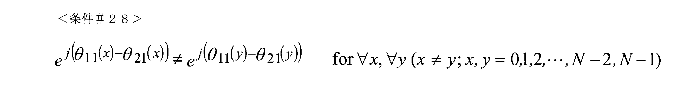
(xは0,1,2,・・・,N-2,N-1であり、yは0,1,2,・・・,N-2,N-1であり、x≠yである。)
(X is 0,1,2, ..., N-2, N-1, y is 0,1,2, ..., N-2, N-1, and x ≠ y. .)

(xは0,1,2,・・・,N-2,N-1であり、yは0,1,2,・・・,N-2,N-1であり、x≠yである。)
そして、以下の条件を付加することを考える。
(X is 0,1,2, ..., N-2, N-1, y is 0,1,2, ..., N-2, N-1, and x ≠ y. .)
Then, consider adding the following conditions.

なお、式(237)のかわりに、次式のプリコーディング行列を与えてもよい。
In addition, instead of the equation (237), the precoding matrix of the following equation may be given.

α>0であるものとし、(iによらず)固定値であるものとする。(式(236)のαと式(238)のαは同一の値であるものとする。)
例として、実施の形態6で説明したように、受信劣悪点を複素平面上において、位相に対し、一様分布となるように配置するために、<条件#31>または<条件#32>を与える。
It is assumed that α> 0 and that it is a fixed value (regardless of i). (It is assumed that α in equation (236) and α in equation (238) have the same value.)
As an example, as described in the sixth embodiment, <


つまり、<条件31>では、位相の差が2π/Nラジアンであることを意味している。また、<条件32>では、位相の差が-2π/Nラジアンであることを意味している。
そして、θ11(0)―θ21(0)=0ラジアンとし、かつ、α>1とし、δ=(3π)/4ラジアンとしたとき、N=4のときのs1の受信劣悪点とs2の受信劣悪点の複素平面
上での配置を図46(a)(b)に示す。このようにすることで、プルコーディング行列を切り替える周期を大きくすることができ、かつ、複素平面において、s1の受信劣悪点の最小距離は大きく保てており、また、同様に、s2の受信劣悪点の最小距離も大きく保つことができるため、良好な受信品質を得ることができる。ここでは、α>1、δ=(3π)/4ラジアン、N=4のときを例に説明したがこれに限ったものではなく、π/2ラジアン
≦|δ|<πラジアン、かつ、α>0、かつ、α≠1であれば同様の効果を得ることができる。
That is, in <
Then, when θ 11 (0) −θ 21 (0) = 0 radians, α> 1, and δ = (3π) / 4 radians, the reception inferior point of s1 and s2 at N = 4 46 (a) and 46 (b) show the arrangement of the poor reception points on the complex plane. By doing so, the period for switching the pull coding matrix can be increased, and the minimum distance of the reception poor point of s1 is kept large in the complex plane, and similarly, the reception poor of s2 is kept large. Since the minimum distance of points can be kept large, good reception quality can be obtained. Here, the case where α> 1, δ = (3π) / 4 radians, and N = 4 is described as an example, but the description is not limited to this, and π / 2 radians ≦ | δ | <π radians and α. If> 0 and α ≠ 1, the same effect can be obtained.
また、<条件#30>と異なる条件として、以下の条件を考える。
Further, the following conditions are considered as conditions different from <

(xはN,N+1,N+2,・・・,2N-2,2N-1であり、yはN,N+1,N+2,・・・,2N-2,2N-1であり、x≠yである。)
(X is N, N + 1, N + 2, ..., 2N-2,2N-1 and y is N, N + 1, N + 2, ..., 2N-2,2N-1 And x ≠ y.)

(xはN,N+1,N+2,・・・,2N-2,2N-1であり、yはN,N+1,N+2,・・・,2N-2,2N-1であり、x≠yである。)
このとき、<条件#28>かつ<条件#29>かつ<条件#33>かつ<条件#34>を満たすことで、複素平面におけるs1同士の受信劣悪点の距離を大きく、かつ、s2同士の受信劣悪点の距離を大きくすることができるため、良好なデータの受信品質を得ることができる。
(X is N, N + 1, N + 2, ..., 2N-2,2N-1 and y is N, N + 1, N + 2, ..., 2N-2,2N-1 And x ≠ y.)
At this time, by satisfying <
本実施の形態では、時間周期2Nのプリコーディングホッピング方法のための2N個の異なるプリコーディング行列の構成方法について説明した。このとき、2N個の異なるプリコーディング行列として、F[0]、F[1]、F[2]、・・・、F[2N-2]、F[2N-1]を用意することになるが、本実施の形態は、シングルキャリア伝送方式のときを例に説明しているため時間軸(または、周波数軸)方向にF[0]、F[1]、F[2]、・・・、F[2N-2]、F[2N-1]の順に並べる場合について説明したが、必ずしもこれに限ったものではなく、本実施の形態で生成した2N個の異なるプリコーディング行列F[0]、F[1]、F[2]、・・・、F[2N-2]、F[2N-1]をOFDM伝送方式等のマルチキャリア伝送方式に適用することもできる。この場合の適用方法については、実施の形態1と同様に、周波数軸、周波数―時間軸に対し、シンボルを配置することで、プリコーディングウェイトを変更することができる。なお、時間周期2Nのプリコーディングホッピング方法として説明しているが、2N個の異なるプリコーディング行列をランダムに用いるようにしても同様の効果を得ることができる、つまり、必ずしも、規則的な周期を持つように2N個の異なるプリコーディング行列を用いる必要はない。 In this embodiment, a method of constructing 2N different precoding matrices for a precoding hopping method having a time period of 2N has been described. At this time, F [0], F [1], F [2], ..., F [2N-2], F [2N-1] are prepared as 2N different precoding matrices. However, since this embodiment is described by taking the case of a single carrier transmission method as an example, F [0], F [1], F [2], ... , F [2N-2], F [2N-1] have been described in this order, but the present invention is not limited to this, and 2N different precoding matrices F [0] generated in the present embodiment have been described. , F [1], F [2], ..., F [2N-2], F [2N-1] can also be applied to multi-carrier transmission methods such as OFDM transmission methods. As for the application method in this case, the precoding weight can be changed by arranging the symbols on the frequency axis and the frequency-time axis as in the first embodiment. Although it is described as a precoding hopping method with a time period of 2N, the same effect can be obtained by randomly using 2N different precoding matrices, that is, a regular period is not always used. You don't have to use 2N different precoding matrices to have.
また、周期H(Hは上記規則的にプリコーディング行列を切り替える方式の周期2Nはより大きな自然数とする)のプリコーディング行列切り替え方法において、本実施の形態における2N個の異なるプリコーディング行列が含まれていると良好な受信品質を与える可能性が高くなる。
(実施の形態12)
本実施の形態では、非ユニタリ行列を用いたプリコーディング行列を規則的に切り替える方法について述べる。
周期Nの規則的にプリコーディング行列を切り替える方法において、周期Nのために用意するプリコーディング行列を次式であらわす。
Further, in the precoding matrix switching method of the period H (H is a larger natural number in the method of regularly switching the precoding matrix), 2N different precoding matrices in the present embodiment are included. If so, it is more likely to give good reception quality.
(Embodiment 12)
In this embodiment, a method of regularly switching the precoding matrix using a non-unitary matrix will be described.
In the method of regularly switching the precoding matrix of the period N, the precoding matrix prepared for the period N is expressed by the following equation.

α>0であるものとし、(iによらず)固定値であるものとする。また、δ≠πラジアン
(iによらず固定値)、i=0,1,2,・・・,N-2,N-1とする。
このとき、実施の形態3の(数106)の条件5、および、(数107)の条件6から、式(239)に対し、以下の条件が、良好なデータの受信品質を得るためには重要となる。
It is assumed that α> 0 and that it is a fixed value (regardless of i). Further, δ ≠ π radian (fixed value regardless of i), i = 0,1,2, ..., N-2, N-1.
At this time, from the

(xは0,1,2,・・・,N-2,N-1であり、yは0,1,2,・・・,N-2,N-1であり、x≠yである。)
(X is 0,1,2, ..., N-2, N-1, y is 0,1,2, ..., N-2, N-1, and x ≠ y. .)

(xは0,1,2,・・・,N-2,N-1であり、yは0,1,2,・・・,N-2,N-1であり、x≠yである。)
例として、実施の形態6で説明したように、受信劣悪点を複素平面上において、位相に対し、一様分布となるように配置するために、<条件#37>または<条件#38>を与える。
(X is 0,1,2, ..., N-2, N-1, y is 0,1,2, ..., N-2, N-1, and x ≠ y. .)
As an example, as described in the sixth embodiment, <


つまり、<条件37>では、位相の差が2π/Nラジアンであることを意味している。また、<条件38>では、位相の差が-2π/Nラジアンであることを意味している。
このとき、π/2ラジアン≦|δ|<πラジアン、かつ、α>0、かつ、α≠1であれば、複素平面におけるs1同士の受信劣悪点の距離を大きく、かつ、s2同士の受信劣悪点の距離を大きくすることができるため、良好なデータの受信品質を得ることができる。なお、<条件#37>、<条件#38>は必ず必要となる条件ではない。
That is, in <
At this time, if π / 2 radian ≦ | δ | <π radian, α> 0, and α ≠ 1, the distance between the reception inferior points between s1s in the complex plane is large, and reception between s2s is large. Since the distance between the inferior points can be increased, good data reception quality can be obtained. It should be noted that <
本実施の形態では、時間周期Nのプリコーディングホッピング方法のためのN個の異なるプリコーディング行列の構成方法について説明した。このとき、N個の異なるプリコーデ
ィング行列として、F[0]、F[1]、F[2]、・・・、F[N-2]、F[N-1]を用意することになるが、本実施の形態は、シングルキャリア伝送方式のときを例に説明しているため時間軸(または、周波数軸)方向にF[0]、F[1]、F[2]、・・・、F[N-2]、F[N-1]の順に並べる場合について説明したが、必ずしもこれに限ったものではなく、本実施の形態で生成した2N個の異なるプリコーディング行列F[0]、F[1]、F[2]、・・・、F[N-2]、F[N-1]をOFDM伝送方式等のマルチキャリア伝送方式に適用することもできる。この場合の適用方法については、実施の形態1と同様に、周波数軸、周波数―時間軸に対し、シンボルを配置することで、プリコーディングウェイトを変更することができる。なお、時間周期Nのプリコーディン
グホッピング方法として説明しているが、N個の異なるプリコーディング行列をランダム
に用いるようにしても同様の効果を得ることができる、つまり、必ずしも、規則的な周期を持つようにN個の異なるプリコーディング行列を用いる必要はない。
In this embodiment, a method of constructing N different precoding matrices for a precoding hopping method having a time period N has been described. At this time, F [0], F [1], F [2], ..., F [N-2], F [N-1] are prepared as N different precoding matrices. However, since this embodiment is described by taking the case of a single carrier transmission method as an example, F [0], F [1], F [2], ... , F [N-2], F [N-1] have been described in this order, but the present invention is not limited to this, and 2N different precoding matrices F [0] generated in the present embodiment have been described. , F [1], F [2], ..., F [N-2], F [N-1] can also be applied to a multi-carrier transmission method such as an OFDM transmission method. As for the application method in this case, the precoding weight can be changed by arranging the symbols on the frequency axis and the frequency-time axis as in the first embodiment. Although it is described as a precoding hopping method having a time period N, the same effect can be obtained by randomly using N different precoding matrices, that is, a regular period is not always used. You don't have to use N different precoding matrices to have.
また、周期H(Hは上記規則的にプリコーディング行列を切り替える方式の周期Nはより
大きな自然数とする)のプリコーディング行列切り替え方法において、本実施の形態におけるN個の異なるプリコーディング行列が含まれていると良好な受信品質を与える可能性
が高くなる。このとき、<条件#35><条件#36>は以下のような条件に置き換えることができる。(周期はNとして考える。)
Further, in the precoding matrix switching method of period H (where H is a method in which the precoding matrix is regularly switched and the period N is a larger natural number), N different precoding matrices in the present embodiment are included. If so, it is more likely to give good reception quality. At this time, <

(xは0,1,2,・・・,N-2,N-1であり、yは0,1,2,・・・,N-2,N-1であり、x≠yである。)
(X is 0,1,2, ..., N-2, N-1, y is 0,1,2, ..., N-2, N-1, and x ≠ y. .)

(xは0,1,2,・・・,N-2,N-1であり、yは0,1,2,・・・,N-2,N-1であり、x≠yである。)
(実施の形態13)
本実施の形態では、実施の形態8の別の例について説明する。
(X is 0,1,2, ..., N-2, N-1, y is 0,1,2, ..., N-2, N-1, and x ≠ y. .)
(Embodiment 13)
In this embodiment, another example of the eighth embodiment will be described.
周期2Nの規則的にプリコーディング行列を切り替える方法において、周期2Nのために用意するプリコーディング行列を次式であらわす。 In the method of regularly switching the precoding matrix with period 2N, the precoding matrix prepared for period 2N is expressed by the following equation.

α>0であるものとし、(iによらず)固定値であるものとする。また、δ≠πラジアン
とする。
It is assumed that α> 0 and that it is a fixed value (regardless of i). Also, let δ ≠ π radians.

α>0であるものとし、(iによらず)固定値であるものとする。(式(240)のαと式(241)のαは同一の値であるものとする。)
そして、式(240)および式(241)をベースとする周期2×N×Mのプリコーディ
ング行列を次式であらわす。
It is assumed that α> 0 and that it is a fixed value (regardless of i). (It is assumed that α in equation (240) and α in equation (241) have the same value.)
Then, the precoding matrix having a period of 2 × N × M based on the equation (240) and the equation (241) is expressed by the following equation.

このとき、k=0,1,・・・,M-2,M-1となる。 At this time, k = 0,1, ..., M-2, M-1.

このとき、k=0,1,・・・,M-2,M-1となる。また、Xk=Ykであってもよいし、Xk≠Ykであ
ってもよい。
すると、F[0]~F[2×N×M-1]のプリコーディング行列が生成されたことになる(F[0]~F[2×N×M-1]のプリコーディング行列は、周期2×N×Mどのような順番にならべて使用し
てもよい。)。そして、例えば、シンボル番号2×N×M×iのときF[0]を用いてプリコー
ディングを行い、シンボル番号2×N×M×i+1のときF[1]を用いてプリコーディングを
行い、・・・、シンボル番号2×N×M×i+hのときF[h]を用いてプリコーディングを行う(h=0、1、2、・・・、2×N×M-2、2×N×M-1)ことになる。(ここでは、以前の実施の形態で述べたように、必ずしも規則的にプリコーディング行列を切り替えなくてもよい。)
このようにプリコーディング行列を生成すると、周期の大きいプリコーディング行列の切り替え方法を実現することができ、受信劣悪点の位置を簡単に変更することができることができ、これが、データの受信品質の向上につながる可能性がある。
At this time, k = 0,1, ..., M-2, M-1. Further, Xk = Yk or Xk ≠ Yk may be satisfied.
Then, the precoding matrix of F [0] to F [2 × N × M-1] is generated (the precoding matrix of F [0] to F [2 × N × M-1] is generated. Cycle 2 x N x M You can use them in any order.) Then, for example, when the symbol number is 2 × N × M × i, precoding is performed using F [0], and when the symbol number is 2 × N × M × i + 1, precoding is performed using F [1]. ..., Precoding is performed using F [h] when the symbol number is 2 × N × M × i + h (h = 0, 1, 2, ・ ・ ・, 2 × N × M-2, 2 × N. × M-1) (Here, as described in the previous embodiment, it is not always necessary to switch the precoding matrix regularly.)
By generating the precoding matrix in this way, it is possible to realize a method of switching the precoding matrix having a large period, and it is possible to easily change the position of the poor reception point, which improves the reception quality of the data. May lead to.
なお、周期2×N×Mのプリコーディング行列の式(242)を次式のようにしてもよい
。
The equation (242) of the precoding matrix having a period of 2 × N × M may be changed to the following equation.

このとき、k=0,1,・・・,M-2,M-1となる。
また、周期2×N×Mのプリコーディング行列の式(243)を式(245)~式(24
7)のいずれかとしてもよい。
At this time, k = 0,1, ..., M-2, M-1.
Further, the equation (243) of the precoding matrix having a period of 2 × N × M is changed from the equation (245) to the equation (24).
It may be any of 7).

このとき、k=0,1,・・・,M-2,M-1となる。
At this time, k = 0,1, ..., M-2, M-1.

このとき、k=0,1,・・・,M-2,M-1となる。 At this time, k = 0,1, ..., M-2, M-1.

このとき、k=0,1,・・・,M-2,M-1となる。
なお、受信劣悪点について着目すると、式(242)から式(247)において、
At this time, k = 0,1, ..., M-2, M-1.
Focusing on the poor reception points, in equations (242) to (247),

(xは0,1,2,・・・,N-2,N-1であり、yは0,1,2,・・・,N-2,N-1であり、x≠yである。) (X is 0,1,2, ..., N-2, N-1, y is 0,1,2, ..., N-2, N-1, and x ≠ y. .)

(xは0,1,2,・・・,N-2,N-1であり、yは0,1,2,・・・,N-2,N-1であり、x≠yである。) (X is 0,1,2, ..., N-2, N-1, y is 0,1,2, ..., N-2, N-1, and x ≠ y. .)

のすべてを満たすと良好なデータの受信品質を得ることができる。なお、実施の形態8では、<条件#39>および<条件#40>を満たすとよい。
また、式(242)から式(247)のXk, Ykに着目すると、
Good data reception quality can be obtained if all of the above are satisfied. In the eighth embodiment, <
Further, focusing on Xk and Yk of equations (242) to (247),

(aは0,1,2,・・・,M-2, M -1であり、bは0,1,2,・・・, M-2, M-1であり、a≠bである。)
ただし、sは整数である。
(A is 0,1,2, ..., M-2, M -1, b is 0,1,2, ..., M-2, M-1, and a ≠ b. .)
However, s is an integer.

(aは0,1,2,・・・,M-2, M -1であり、bは0,1,2,・・・, M-2, M-1であり、a≠bである。)
ただし、uは整数である。
(A is 0,1,2, ..., M-2, M -1, b is 0,1,2, ..., M-2, M-1, and a ≠ b. .)
However, u is an integer.
の2つの条件を満たすと良好なデータの受信品質を得ることができる。なお、実施の形態8では、<条件42>を満たすとよい。
なお、式(242)および式(247)において、0ラジアン≦δ<2πラジアンとしたとき、δ=πラジアンのときユニタリ行列となり、δ≠πラジアンのとき非ユニタリ行列となる。本方式では、π/2ラジアン≦|δ|<πラジアンの非ユニタリ行列のときが一つの特徴的な構成であり、良好なデータの受信品質が得られることになる。別の構成として、ユニタリ行列の場合もあるが、実施の形態10や実施の形態16において、詳しく述べるが、式(242)から式(247)において、Nを奇数とすると、良好なデータの
受信品質を得ることができる可能性が高くなる。
Good data reception quality can be obtained if the above two conditions are satisfied. In the eighth embodiment, <condition 42> may be satisfied.
In equations (242) and (247), when 0 radian ≤ δ <2π radian, a unitary matrix is obtained when δ = π radian, and a non-unitary matrix is obtained when δ ≠ π radian. In this method, a non-unitary matrix of π / 2 radians ≦ | δ | <π radians is one characteristic configuration, and good data reception quality can be obtained. As another configuration, there is a case of a unitary matrix, which will be described in detail in the tenth embodiment and the sixteenth embodiment, but when N is an odd number in the equations (242) to (247), good data reception is received. The chances of getting quality are high.
(実施の形態14)
本実施の形態では、規則的にプリコーディング行列を切り替える方式において、プリコーディング行列として、ユニタリ行列を用いる場合と非ユニタリ行列を用いる場合の使い分けの例について説明する。
(Embodiment 14)
In the present embodiment, an example of properly using a unitary matrix and a non-unitary matrix as the precoding matrix in the method of regularly switching the precoding matrix will be described.
例えば、2行2列のプリコーディング行列(各要素は複素数で構成されているものとする)を用いた場合、つまり、ある変調方式に基づいた2つの変調信号(s1(t)およびs2(t))に対し、プリコーディングを施し、プリコーディング後の2つの信号を2つのアンテナから送信する場合について説明する。
規則的にプリコーディング行列を切り替える方法を用いてデータを伝送する場合、図3の
図13の送信装置は、フレーム構成信号313により、マッピング部306A、306Bは、変調方式を切り替えることになる。このとき、変調方式の変調多値数(変調多値数:IQ平面における変調方式の信号点の数)とプリコーディング行列の関係について説明する。
For example, when using a 2-by-2 precoding matrix (each element is assumed to be composed of complex numbers), that is, two modulation signals based on a certain modulation scheme (s1 (t) and s2 (t). A case where precoding is applied to)) and two signals after precoding are transmitted from two antennas will be described.
When data is transmitted using the method of regularly switching the precoding matrix, the transmission device of FIG. 13 in FIG. 3 uses the
規則的にプリコーディング行列を切り替える方法の利点は、実施の形態6において説明したようにLOS環境において、良好なデータの受信品質を得ることができる点であり、特に、受信装置がML演算やML演算に基づくAPP(または、Max-log APP)を施した場合、その効果が大きい。ところで、ML演算は、変調方式の変調多値数に伴い、回路規模(演算規模)に大きな影響を与える。例えば、プリコーディング後の2つの信号を2つのアンテナから送信し、2つの変調信号(プリコーディング前の変調方式に基づく信号)がいずれも同一の変調方式を用いているものとする場合、変調方式がQPSKの場合、IQ平面における候補信号点(図11の受信信号点1101)の数は4×4=16個、16QAMの場合16×16=256個、64QAMの場合64×64=4096個、256QAMの場合256×256=65536個、1024QAMの場合1024×1024=1048576個となり、受信装置の演算規模をある程度の回路規模で抑えるためには、変調方
式がQPSK, 16QAM, 64QAMの場合は、受信装置において、ML演算(ML演算に基づく(Max-log)APP)を用い、256QAM, 1024QAMの場合は、MMSE, ZFのような線形演算を用いた検波を
用いることになる。(場合によっては、256QAMの場合、ML演算を用いても良い。)
このような受信装置を想定した場合、多重信号分離後のSNR(signal-to-noise power ratio)を考えた場合、受信装置でMMSE, ZFのような線形演算を用いている場合は、プリコーディング行列としてユニタリ行列が適しており、ML演算を用いている場合は、プリコーディング行列としてユニタリ行列・非ユニタリ行列のいずれをもちいてもよい。上述のいずれかの実施の形態の説明を考慮すると、プリコーディング後の2つの信号を2つのアンテナから送信し、2つの変調信号(プリコーディング前の変調方式に基づく信号)がいずれも同一の変調方式を用いているものとする場合、変調方式の変調多値数が64値以下(または、256値以下)のとき、規則的にプリコーディング行列を切り替える方式を用いたと
きのプリコーディング行列として非ユニタリ行列を用い、64値より大きい(または256値
より大きい)場合、ユニタリ行列を用いると、通信システムがサポートしている全ての変調方式において、どの変調方式の場合においても、受信装置の回路規模を小さくしながら良好なデータの受信品質を得ることができるという効果を得ることができる可能性が高くなる。
The advantage of the method of regularly switching the precoding matrix is that good data reception quality can be obtained in the LOS environment as described in the sixth embodiment, and in particular, the receiving device can perform ML operation or ML. When APP (or Max-log APP) based on calculation is applied, the effect is great. By the way, the ML calculation has a great influence on the circuit scale (calculation scale) with the number of modulation multi-values of the modulation method. For example, when two signals after precoding are transmitted from two antennas and two modulation signals (signals based on the modulation method before precoding) both use the same modulation method, the modulation method When is QPSK, the number of candidate signal points (received signal points 1101 in FIG. 11) in the IQ plane is 4 × 4 = 16, 16 × 16 = 256 for 16QAM, 64 × 64 = 4096 for 64QAM, In the case of 256QAM, it is 256 × 256 = 65536, and in the case of 1024QAM, it is 1024 × 1024 = 1048576. In the device, ML operation ((Max-log) APP based on ML operation) is used, and in the case of 256QAM and 1024QAM, detection using linear operation such as MMSE and ZF is used. (In some cases, in the case of 256QAM, ML operation may be used.)
Assuming such a receiver, when considering the SNR (signal-to-noise power ratio) after multiplex signal separation, precoding when the receiver uses linear operations such as MMSE and ZF. When a unitary matrix is suitable as a matrix and ML operation is used, either a unitary matrix or a non-unitary matrix may be used as the precoding matrix. Considering the description of any of the above embodiments, the two signals after precoding are transmitted from the two antennas, and the two modulation signals (signals based on the modulation method before precoding) are both the same modulation. When the method is used, when the number of modulation multi-values of the modulation method is 64 values or less (or 256 values or less), it is not a precoding matrix when the method of regularly switching the precoding matrix is used. If a unitary matrix is used and is greater than 64 values (or 256 values), then a unitary matrix can be used for all modulation schemes supported by the communication system and for any modulation scheme of the receiver. There is a high possibility that the effect of being able to obtain good data reception quality can be obtained while reducing the value.
また、変調方式の変調多値数が64値以下(または、256値以下)の場合においてもユニ
タリ行列を用いたほうがよい場合がある可能性がある。このようなことを考慮すると、変調方式の変調多値数が64値以下(または、256値以下)の複数の変調方式をサポートして
いる場合、サポートしている複数の64値以下の変調方式のいずれかの変調方式で規則的にプリコーディング行列を切り替える方式を用いたときのプリコーディング行列として非ユニタリ行列を用いる場合が存在することが重要となる。
In addition, it may be better to use a unitary matrix even when the number of modulation multi-values of the modulation method is 64 values or less (or 256 values or less). Considering this, if the modulation method supports multiple modulation methods with 64 values or less (or 256 values or less), the supported multiple modulation methods with 64 values or less. It is important that there is a case where a non-unitary matrix is used as the precoding matrix when the precoding matrix is regularly switched by any of the modulation methods.
上述では、一例として、プリコーディング後の2つの信号を2つのアンテナから送信する場合について説明したが、これに限ったものではなく、プリコーディング後のN個の信
号をN個のアンテナから送信し、N個の変調信号(プリコーディング前の変調方式に基づく信号)がいずれも同一の変調方式を用いているものとする場合、変調方式の変調多値数にβNという閾値を設け、変調方式の変調多値数がβN以下の複数の変調方式をサポートしている場合、サポートしているβN以下の複数の変調方式のいずれかの変調方式で規則的に
プリコーディング行列を切り替える方式を用いたときのプリコーディング行列として非ユニタリ行列を用いる場合が存在し、変調方式の変調多値数がβNより大きい変調方式の場
合、ユニタリ行列を用いると、通信システムがサポートしている全ての変調方式において、どの変調方式の場合においても、受信装置の回路規模を小さくしながら良好なデータの受信品質を得ることができるという効果を得ることができる可能性が高くなる。(変調方
式の変調多値数がβN以下のとき、規則的にプリコーディング行列を切り替える方式を用
いたときのプリコーディング行列として非ユニタリ行列を常に用いてもよい。)
上述では、同時に送信するN個の変調信号の変調方式が、同一の変調方式を用いている
場合で説明したが、以下では、同時に送信するN個の変調信号において、2種類以上の変
調方式が存在する場合について説明する。
In the above, as an example, the case where two precoded signals are transmitted from two antennas has been described, but the present invention is not limited to this, and N precoded signals are transmitted from N antennas. , When it is assumed that the N modulation signals (signals based on the modulation method before precoding) all use the same modulation method, a threshold value of β N is set for the number of modulation multi-values of the modulation method, and the modulation method is used. If multiple modulation methods with a multi-valued number of β N or less are supported, the method of regularly switching the precoding matrix with one of the supported modulation methods of β N or less is used. In some cases, a non-unitary matrix is used as the precoding matrix when used, and in the case of a modulation method in which the modulation multi-value number of the modulation method is larger than β N , the unitary matrix is used for all the support of the communication system. In any modulation method, there is a high possibility that the effect of being able to obtain good data reception quality while reducing the circuit scale of the receiving device can be obtained. (When the modulation multi-value number of the modulation method is β N or less, a non-unitary matrix may always be used as the precoding matrix when the method of regularly switching the precoding matrix is used.)
In the above, the case where the same modulation method is used for the modulation methods of the N modulation signals transmitted at the same time has been described, but in the following, two or more types of modulation methods are used for the N modulation signals transmitted at the same time. The case where it exists will be described.
例として、プリコーディング後の2つの信号を2つのアンテナから送信する場合について説明する。2つの変調信号(プリコーディング前の変調方式に基づく信号)がいずれも同一の変調方式、または、異なる変調方式であるものとしたとき、変調多値数が2a1値の変調方式と変調多値数が2a2値の変調方式を用いているものとする。このとき、受信装置においてML演算(ML演算に基づく(Max-log)APP)を用いている場合、IQ平面における候補信号点(図11の受信信号点1101)の数は、2a1×2a2=2a1+a2の候補信号点が存在することになる。このとき、上記で述べたように、受信装置の回路規模を小さくしながら良好なデータの受信品質を得ることができるためには、2a1+a2に対し2βという閾値を設け、2a1+a2≦2βのとき、規則的にプリコーディング行列を切り替える方式を用いたときのプリコーディング行列として非ユニタリ行列を用い、2a1+a2>2β場合、ユニタリ行列を用いるとよい。 As an example, a case where two signals after precoding are transmitted from two antennas will be described. Assuming that the two modulation signals (signals based on the modulation method before precoding) are both the same modulation method or different modulation methods, the modulation method having a modulation multi-value number of 2a1 and the modulation multi-value It is assumed that a modulation method in which the number is 2a2 is used. At this time, when the ML operation ((Max-log) APP based on the ML operation) is used in the receiving device, the number of candidate signal points (received signal points 1101 in FIG. 11) in the IQ plane is 2 a1 × 2 a2 . = 2 There will be candidate signal points for a1 + a2 . At this time, as described above, in order to obtain good data reception quality while reducing the circuit scale of the receiving device, a threshold value of 2 β is set for 2 a1 + a2 , and 2 a1 + a2 ≤ 2 β . At this time, it is preferable to use a non-unitary matrix as the precoding matrix when the method of regularly switching the precoding matrix is used, and when 2 a1 + a2 > 2 β , the unitary matrix should be used.
また、2a1+a2≦2βの場合においてもユニタリ行列を用いたほうがよい場合がある可能性がある。このようなことを考慮すると、2a1+a2≦2βの複数の変調方式の組み合わせをサポートしている場合、サポートしている2a1+a2≦2βの複数の変調方式の組み合わせのいずれかの変調方式の組み合わせで規則的にプリコーディング行列を切り替える方式を用いたときのプリコーディング行列として非ユニタリ行列を用いる場合が存在することが重要となる。 Further, even in the case of 2 a1 + a2 ≤ 2 β , it may be better to use the unitary matrix. Considering this, when a combination of a plurality of modulation methods of 2 a1 + a2 ≤ 2 β is supported, one of the supported modulation methods of a combination of a plurality of modulation methods of 2 a1 + a2 ≤ 2 β is supported. It is important that there is a case where a non-unitary matrix is used as the precoding matrix when the method of regularly switching the precoding matrix by the combination is used.
上述では、一例として、プリコーディング後の2つの信号を2つのアンテナから送信する場合について説明したが、これに限ったものではない。例えば、N個の変調信号(プリ
コーディング前の変調方式に基づく信号)がいずれも同一の変調方式、または、異なる変調方式が存在する場合のとき、第iの変調信号の変調方式の変調多値数を2aiとする(i=1、2、・・・、N-1、N)。
In the above, as an example, the case where the two signals after precoding are transmitted from the two antennas has been described, but the present invention is not limited to this. For example, when the N modulation signals (signals based on the modulation method before precoding) all have the same modulation method or different modulation methods, the modulation multi-value of the modulation method of the i-th modulation signal Let the number be 2 ai (i = 1, 2, ..., N-1, N).
このとき、受信装置においてML演算(ML演算に基づく(Max-log)APP)を用いている場合、IQ平面における候補信号点(図11の受信信号点1101)の数は、2a1×2a2×・・・×2ai×・・・×2aN=2a1+a2+・・・+ai+・・・+aNの候補信号点が存在することになる。このとき、上記で述べたように、受信装置の回路規模を小さくしながら良好なデータの受信品質を得ることができるためには、2a1+a2+・・・+ai+・・・+aNに対し2βという閾値を設け、 At this time, when the ML operation ((Max-log) APP based on the ML operation) is used in the receiving device, the number of candidate signal points (received signal points 1101 in FIG. 11) in the IQ plane is 2 a1 × 2 a2 . × ・ ・ ・ × 2 ai × ・ ・ ・ × 2 aN = 2 a1 + a2 + ・ ・ ・ + ai + ・ ・ ・ + aN candidate signal points exist. At this time, as described above, in order to obtain good data reception quality while reducing the circuit scale of the receiving device, a threshold value of 2 β for 2 a1 + a2 + ... + ai + ... + aN is obtained. And set up

<条件#44>を満たす複数の変調方式の組み合わせをサポートしている場合、サポートしている<条件#44>を満たす複数の変調方式の組み合わせのいずれかの変調方式の組み合わせで規則的にプリコーディング行列を切り替える方式を用いたときのプリコーディング行列として非ユニタリ行列を用いる場合が存在し、 When a combination of a plurality of modulation methods satisfying <Condition # 44> is supported, a combination of a plurality of modulation methods satisfying the supported <Condition # 44> is regularly preliminarily used. There are cases where a non-unitary matrix is used as the precoding matrix when the method of switching the coding matrix is used.

<条件#45>を満たすすべての変調方式の組み合わせの場合、ユニタリ行列を用いると、通信システムがサポートしている全ての変調方式において、どの変調方式の組み合わせの場合においても、受信装置の回路規模を小さくしながら良好なデータの受信品質を得ることができるという効果を得ることができる可能性が高くなる。(サポートしている<条件#44>を満たす複数の変調方式の組み合わせすべてにおいて、規則的にプリコーディング行列を切り替える方式を用いたときのプリコーディング行列として非ユニタリ行列を用いてもよい。)
(実施の形態15)
本実施の形態では、OFDMのようなマルチキャリア伝送方式を用いた、規則的にプリコーディング行列を切り替える方式のシステム例について説明する。
In the case of all the modulation method combinations that satisfy <Condition # 45>, if a unitary matrix is used, the circuit scale of the receiver device is used regardless of the modulation method combination in all the modulation methods supported by the communication system. There is a high possibility that the effect of being able to obtain good data reception quality can be obtained while reducing the size. (A non-unitary matrix may be used as the precoding matrix when the method of regularly switching the precoding matrix is used in all combinations of a plurality of modulation methods that satisfy the supported <condition # 44>.)
(Embodiment 15)
In this embodiment, a system example of a method of regularly switching precoding matrices using a multi-carrier transmission method such as OFDM will be described.
図47は、本実施の形態におけるOFDMのようなマルチキャリア伝送方式を用いた、規則的にプリコーディング行列を切り替える方式のシステムにおいて、放送局(基地局)が送信する送信信号の、時間-周波数軸におけるフレーム構成の一例を示している。(時間$1から時間$Tまでのフレーム構成とする。)図47(A)は、実施の形態1等で説明したストリームs1の時間-周波数軸におけるフレーム構成、図47(B)は、実施の形態1等で説明したストリームs2の時間-周波数軸におけるフレーム構成を示している。ストリームs1とストリームs2の同一時間、同一(サブ)キャリアのシンボルは、複数のアンテナを用いて、同一時間、同一周波数で送信されることになる。 FIG. 47 shows the time-frequency of a transmission signal transmitted by a broadcasting station (base station) in a system of a method of regularly switching precoding matrices using a multi-carrier transmission method such as OFDM in the present embodiment. An example of the frame configuration on the axis is shown. (The frame configuration is from time $ 1 to time $ T.) FIG. 47 (A) is a frame configuration on the time-frequency axis of the stream s1 described in the first embodiment and the like, and FIG. 47 (B) is an embodiment. The frame configuration on the time-frequency axis of the stream s2 described in the first embodiment and the like is shown. The symbols of the same time and the same (sub) carrier of the stream s1 and the stream s2 will be transmitted at the same time and the same frequency by using a plurality of antennas.
図47(A)(B)では、OFDMを用いたときに使用される(サブ)キャリアは、(サブ)キャリアa~(サブ)キャリアa+Naで構成されたキャリア群#A、(サブ)キャリアb~(サブ)キャリアb+Nbで構成されたキャリア群#B、(サブ)キャリアc~(サブ)キャリアc+Ncで構成されたキャリア群#C、(サブ)キャリアd~(サブ)キャリアd+Ndで構成されたキャリア群#D、・・・で分割するものとする。そして、各サブキャリア群では、複数の送信方法をサポートするものとする。ここで、複数の送信方法をサポートすることで、各送信方法がもつ利点を効果的に活用することが可能となる。例えば、図47(A)(B)では、キャリア群#Aは、空間多重MIMO伝送方式、または、プリコーディング行列が固定のMIMO伝送方式を用いるものとし、キャリア群#Bは規則的にプリコーディング行列を切り替えるMIMO伝送方式を用いるものとし、キャリア群#Cはストリームs1のみ送信し、キャリア群#Dは時空間ブロック符号を用いて送信するものとする。 In FIGS. 47 (A) and 47 (B), the (sub) carriers used when OFDM is used are carrier group # A and (sub) carrier b composed of (sub) carriers a to (sub) carriers a + Na. ~ (Sub) carrier group #B composed of (sub) carrier b + Nb, (sub) carrier c ~ (sub) carrier group #C composed of (sub) carrier c + Nc, (sub) carrier d ~ (sub) carrier d + Nd. It shall be divided by carrier group # D, .... Then, each subcarrier group shall support a plurality of transmission methods. Here, by supporting a plurality of transmission methods, it is possible to effectively utilize the advantages of each transmission method. For example, in FIGS. 47 (A) and 47 (B), the carrier group #A uses a spatial multiplex MIMO transmission method or a MIMO transmission method in which the precoding matrix is fixed, and the carrier group #B is regularly precoded. It is assumed that the MIMO transmission method for switching the matrix is used, the carrier group #C transmits only the stream s1, and the carrier group #D transmits using the spatiotemporal block code.
図48は、本実施の形態におけるOFDMのようなマルチキャリア伝送方式を用いた、規則的にプリコーディング行列を切り替える方式のシステムにおいて、放送局(基地局)が送信する送信信号の、時間-周波数軸におけるフレーム構成の一例を示しており、図47とは異なる時間の時間$Xから時間$X+T’までのフレーム構成を示している。図48は、図47と同様に、OFDMを用いたときに使用される(サブ)キャリアは、(サブ)キャリアa~(サブ)キャリアa+Naで構成されたキャリア群#A、(サブ)キャリアb~(サブ)キャリアb+Nbで構成されたキャリア群#B、(サブ)キャリアc~(サブ)キャリアc+Ncで構成されたキャリア群#C、(サブ)キャリアd~(サブ)キャリアd+Ndで構成されたキャリア群#D、・・・で分割するものとする。そして、図48が図47と異なる点は、図47で用いられている通信方式と図48で用いられている通信方式が異なるキャリア群が存在することである。図48では、(A)(B)では、キャリア群#Aは、時空間ブロック符号を用いて送信するものとし、キャリア群#Bは規則的にプリコーディング行列を切り替えるMIMO伝送方式を用いるものとし、キャリア群#Cは規則的にプリコーディング行列を切り替えるMIMO伝送方式を用いるものとし、キャリア群#Dはストリームs1のみ送信するものとする。 FIG. 48 shows the time-frequency of a transmission signal transmitted by a broadcasting station (base station) in a system of a method of regularly switching precoding matrices using a multi-carrier transmission method such as OFDM in the present embodiment. An example of the frame configuration on the axis is shown, and the frame configuration from the time $ X to the time $ X + T'different from that in FIG. 47 is shown. In FIG. 48, similarly to FIG. 47, the (sub) carriers used when OFDM is used are carrier group #A and (sub) carrier b composed of (sub) carriers a to (sub) carriers a + Na. ~ (Sub) carrier group #B composed of (sub) carrier b + Nb, (sub) carrier c ~ (sub) carrier group #C composed of (sub) carrier c + Nc, (sub) carrier d ~ (sub) carrier d + Nd. It shall be divided by carrier group # D, .... The difference between FIG. 48 and FIG. 47 is that there is a carrier group in which the communication method used in FIG. 47 and the communication method used in FIG. 48 are different. In FIGS. 48 (A) and (B), the carrier group #A shall be transmitted using a spatiotemporal block code, and the carrier group #B shall use a MIMO transmission method in which the precoding matrix is regularly switched. , Carrier group #C shall use a MIMO transmission method that regularly switches the precoding matrix, and carrier group #D shall transmit only the stream s1.
次に、サポートする送信方法について説明する。
図49は、空間多重MIMO伝送方式、または、プリコーディング行列が固定のMIMO伝送方式を用いたときの信号処理方法を示しており、図6と同様の番号を付している。ある変調方式にしたがったベースバンド信号である、重み付け合成部600は、ストリームs1(t)(307A)およびストリームs2(t)(307B)、および、重み付け方法に関する情報315を入力とし、重み付け後の変調信号z1(t)(309A)および重み付け後の変調信号z2(t)(309B)を出力する。ここで、重み付け方法に関する情報315が、空間多重MIMO伝送方式を示していた場合、図49の方式#1の信号処理が行われる。つまり、以下の処理が行われる。
Next, the supported transmission methods will be described.
FIG. 49 shows a signal processing method when a spatial multiplex MIMO transmission method or a MIMO transmission method having a fixed precoding matrix is used, and is numbered in the same manner as in FIG. The

ただし、1つの変調信号を送信する方式をサポートしている場合、送信電力の点から、式(250)は、式(251)のようにあらわされることもある。 However, when a method of transmitting one modulated signal is supported, the equation (250) may be expressed as the equation (251) in terms of transmission power.

そして、重み付け方法に関する情報315が、プリコーディング行列が固定のMIMO伝送方式を示している場合、例えば、図49の方式#2の信号処理が行われる。つまり、以下の処理が行われる。
Then, when the

ここで、θ11、θ12、λ、δは固定値となる。
図50は、時空間ブロック符号を用いたときの変調信号の構成を示している。図50の時空間ブロック符号化部(5002)は、ある変調信号に基づくベースバンド信号が入力とする。例えば、時空間ブロック符号化部(5002)は、シンボルs1、シンボルs2、・・・を入力とする。すると、図50のように、時空間ブロック符号化が行われ、z1(5003A)は、「シンボル#0としてs1」「シンボル#1として-s2*」「シンボル#2としてs3」「シンボル#3として-s4*」・・・となり、z2(5003B)は、「シンボル#0としてs2」「シンボル#1としてs1*」「シンボル#2としてs4」「シンボル#3としてs3*」・・・となる。このとき、z1におけるシンボル#X、z2におけるシンボル#Xは同一時間に同一周波数によりアンテナから送信されることになる。
Here, θ11, θ12, λ, and δ are fixed values.
FIG. 50 shows the configuration of the modulated signal when the spatiotemporal block code is used. The spatio-temporal block coding unit (5002) of FIG. 50 receives a baseband signal based on a certain modulated signal as an input. For example, the space-time block coding unit (5002) inputs symbols s1, symbols s2, .... Then, as shown in FIG. 50, spatiotemporal block coding is performed, and z1 (5003A) is "s1 as
図47、図48では、データを伝送するシンボルのみを記載しているが、実際には、伝送方式、変調方式、誤り訂正方式等の情報を伝送する必要がある。例えば、図51のように、1つの変調信号z1のみでこれらの情報を定期的に伝送すれば、これらの情報を通信相手に伝送することができる。また、伝送路の変動、つまり、受信装置がチャネル変動を推定するためのシンボル(例えば、パイロットシンボル、リファレンスシンボル、プリアンブル、送受信で既知の(PSK:Phase Shift Keying)シンボル)を伝送する必要がある。図47、図48では、これらのシンボルを省略して記述しているが、実際は、チャネル変動を推定するためのシンボルが時間―周波数軸のフレーム構成において、含まれることになる。したがって、各キャリア群は、データを伝送するためのシンボルのみだけで構成されているわけではない。(この点については、実施の形態1においても同様である。)
図52は、本実施の形態における放送局(基地局)の送信装置の構成の一例を示している。送信方法決定部(5205)は、各キャリア群のキャリア数、変調方式、誤り訂正方式、誤り訂正符号の符号化率、送信方法等の決定を行い、制御信号(5205)として出力する。
Although only the symbols for transmitting data are shown in FIGS. 47 and 48, it is actually necessary to transmit information such as a transmission method, a modulation method, and an error correction method. For example, as shown in FIG. 51, if these information are periodically transmitted by only one modulation signal z1, these information can be transmitted to the communication partner. In addition, it is necessary to transmit the fluctuation of the transmission line, that is, the symbol for estimating the channel fluctuation of the receiving device (for example, a pilot symbol, a reference symbol, a preamble, and a known phase shift keying (PSK) symbol). .. Although these symbols are omitted in FIGS. 47 and 48, in reality, symbols for estimating channel fluctuations are included in the frame configuration of the time-frequency axis. Therefore, each carrier group is not composed only of symbols for transmitting data. (This point is the same in the first embodiment.)
FIG. 52 shows an example of the configuration of the transmission device of the broadcasting station (base station) in the present embodiment. The transmission method determination unit (5205) determines the number of carriers in each carrier group, the modulation method, the error correction method, the coding rate of the error correction code, the transmission method, and the like, and outputs the control signal (5205).
変調信号生成部#1(5201_1)は、情報(5200_1)および制御信号(5205)を入力とし、制御信号(5205)の通信方式の情報に基づき、図47、図48のキャリア群#Aの変調信号z1(5202_1)および変調信号z2(5203_1)を出力する。 The modulation signal generation unit # 1 (5201_1) receives information (5200_1) and a control signal (5205) as inputs, and modulates the carrier group # A in FIGS. 47 and 48 based on the information of the communication method of the control signal (5205). The signal z1 (5202_1) and the modulation signal z2 (5203_1) are output.
同様に、変調信号生成部#2(5201_2)は、情報(5200_2)および制御信号(5205)を入力とし、制御信号(5205)の通信方式の情報に基づき、図47、図48のキャリア群#Bの変調信号z1(5202_2)および変調信号z2(5203
_2)を出力する。
Similarly, the modulation signal generation unit # 2 (5201_2) takes the information (5200_2) and the control signal (5202) as inputs, and based on the information of the communication method of the control signal (5205), the carrier group # of FIGS. 47 and 48. B modulation signal z1 (5202_1) and modulation signal z2 (5203)
_2) is output.
同様に、変調信号生成部#3(5201_3)は、情報(5200_3)および制御信号(5205)を入力とし、制御信号(5205)の通信方式の情報に基づき、図47、図48のキャリア群#Cの変調信号z1(5202_3)および変調信号z2(5203_3)を出力する。 Similarly, the modulation signal generation unit # 3 (5201_3) takes the information (5200_3) and the control signal (5205) as inputs, and based on the information of the communication method of the control signal (5205), the carrier group # of FIGS. 47 and 48. The modulation signal z1 (5202_3) and the modulation signal z2 (5203_3) of C are output.
同様に、変調信号生成部#4(5201_4)は、情報(5200_4)および制御信号(5205)を入力とし、制御信号(5205)の通信方式の情報に基づき、図47、図48のキャリア群#Dの変調信号z1(5202_4)および変調信号z2(5203_4)を出力する。 Similarly, the modulation signal generation unit # 4 (5201_4) takes the information (5200_4) and the control signal (5205) as inputs, and based on the information of the communication method of the control signal (5205), the carrier group # of FIGS. 47 and 48. The modulation signal z1 (5202_4) and the modulation signal z2 (5203_4) of D are output.
・
・
・
同様に、変調信号生成部#M(5201_M)は、情報(5200_M)および制御信号(5205)を入力とし、制御信号(5205)の通信方式の情報に基づき、あるキャリア群の変調信号z1(5202_M)および変調信号z2(5203_M)を出力する。
・
・
・
Similarly, the modulation signal generation unit # M (5201_M) receives information (5200_M) and a control signal (5205) as inputs, and based on the information of the communication method of the control signal (5205), the modulation signal z1 (5202_M) of a certain carrier group. ) And the modulation signal z2 (5203_M).
OFDM方式関連処理部(5207_1)は、キャリア群#Aの変調信号z1(5202_1)、キャリア群#Bの変調信号z1(5202_2)、キャリア群#Cの変調信号z1(5202_3)、キャリア群#Dの変調信号z1(5202_4)、・・・、あるキャリア群の変調信号z1(5202_M)、および、制御信号(5206)を入力とし、並び換え、逆フーリエ変換、周波数変換、増幅等の処理を施し、送信信号(5208_1)を出力し、送信信号(5208_1)は、アンテナ(5209_1)から電波として出力される。 The OFDM system related processing unit (5207_1) includes a modulation signal z1 (5202_1) of the carrier group #A, a modulation signal z1 (5202_1) of the carrier group #B, a modulation signal z1 (5202_1) of the carrier group #C, and a carrier group #D. Modulation signal z1 (5202_4), ..., Modulation signal z1 (5202_M) of a certain carrier group, and control signal (5206) are used as inputs, and processing such as rearrangement, inverse Fourier conversion, frequency conversion, and amplification is performed. , The transmission signal (5208_1) is output, and the transmission signal (5208_1) is output as a radio wave from the antenna (5209_1).
同様に、OFDM方式関連処理部(5207_2)は、キャリア群#Aの変調信号z1(5203_1)、キャリア群#Bの変調信号z2(5203_2)、キャリア群#Cの変調信号z2(5203_3)、キャリア群#Dの変調信号z2(5203_4)、・・・、あるキャリア群の変調信号z2(5203_M)、および、制御信号(5206)を入力とし、並び換え、逆フーリエ変換、周波数変換、増幅等の処理を施し、送信信号(5208_2)を出力し、送信信号(5208_2)は、アンテナ(5209_2)から電波として出力される。 Similarly, the OFDM method related processing unit (5207_2) includes the modulation signal z1 (5203_1) of the carrier group #A, the modulation signal z2 (5203_1) of the carrier group #B, the modulation signal z2 (5203_1) of the carrier group #C, and the carrier. Modulation signal z2 (5203_4) of group # D, ..., Modulation signal z2 (5203_M) of a certain carrier group, and control signal (5206) are used as inputs, and rearrangement, inverse Fourier conversion, frequency conversion, amplification, etc. are performed. Processing is performed, the transmission signal (5208_2) is output, and the transmission signal (5208_2) is output as a radio wave from the antenna (5209_2).
図53は、図52の変調信号生成部#1~#Mの構成の一例を示している。誤り訂正符号化部(5302)は、情報(5300)および、制御信号(5301)を入力とし、制御信号(5301)にしたがって、誤り訂正符号化方式、誤り訂正符号化の符号化率を設定し、誤り訂正符号化を行い、誤り訂正符号化後のデータ(5303)を出力する。(誤り訂正符号化方式、誤り訂正符号化の符号化率の設定により、例えば、LDPC符号、ターボ符号、畳み込み符号等を用いたとき、符号化率によっては、パンクチャを行い、符号化率を実現する場合がある。)
インタリーブ部(5304)は、誤り訂正符号化後のデータ(5303)、制御信号(5301)を入力とし、制御信号(5301)に含まれるインタリーブ方法の情報に従い、誤り訂正符号化後のデータ(5303)の並び換えを行い、インタリーブ後のデータ(5305)を出力する。
FIG. 53 shows an example of the configuration of the modulation signal
The interleaving unit (5304) takes data after error correction coding (5303) and a control signal (5301) as inputs, and follows the information of the interleaving method included in the control signal (5301), and the data after error correction coding (5303). ) Is rearranged, and the interleaved data (5305) is output.
マッピング部(5306_1)は、インタリーブ後のデータ(5305)および制御信号(5301)を入力とし、制御信号(5301)に含まれる変調方式の情報に従い、マ
ッピング処理を行い、ベースバンド信号(5307_1)を出力する。
The mapping unit (5306_1) receives the interleaved data (5305) and the control signal (5301) as inputs, performs mapping processing according to the information of the modulation method included in the control signal (5301), and outputs the baseband signal (5307_1). Output.
同様に、マッピング部(5306_2)は、インタリーブ後のデータ(5305)および制御信号(5301)を入力とし、制御信号(5301)に含まれる変調方式の情報に従い、マッピング処理を行い、ベースバンド信号(5307_2)を出力する。 Similarly, the mapping unit (5306_2) takes the interleaved data (5305) and the control signal (5301) as inputs, performs mapping processing according to the information of the modulation method included in the control signal (5301), and performs the mapping process to the baseband signal (5301). 5307_2) is output.
信号処理部(5308)は、ベースバンド信号(5307_1)、ベースバンド信号(5307_2)および制御信号(5301)を入力とし、制御信号(5301)に含まれる伝送方法(ここでは、例えば、空間多重MIMO伝送方式、固定的なプリコーディング行列を用いるMIMO方式、規則的にプリコーディング行列を切り替えるMIMO方式、時空間ブロック符号化、ストリームs1のみ送信する伝送方式)の情報に基づき、信号処理を行い、信号処理後の信号z1(5309_1)および信号処理後のz2(5309_2)を出力する。なお、ストリームs1のみを送信する伝送方式が選択された場合、信号処理部(5308)は、信号処理後のz2(5309_2)を出力しないこともある。また、図53では、誤り訂正符号化部が一つの場合の構成を示したがこれに限ったものではなく、例えば、図3に示すように、複数の符号化器を具備していてもよい。 The signal processing unit (5308) inputs the baseband signal (5307_1), the baseband signal (5307_2), and the control signal (5301), and the transmission method included in the control signal (5301) (here, for example, spatial multiplexing MIMO). Signal processing is performed based on the information of the transmission method, the MIMO method using a fixed precoding matrix, the MIMO method that switches the precoding matrix regularly, the spatiotemporal block coding, and the transmission method that transmits only the stream s1). The processed signal z1 (5309_1) and the processed signal z2 (5309_1) are output. When the transmission method for transmitting only the stream s1 is selected, the signal processing unit (5308) may not output the z2 (5309_2) after the signal processing. Further, FIG. 53 shows a configuration in which there is only one error correction coding unit, but the configuration is not limited to this, and for example, as shown in FIG. 3, a plurality of encoders may be provided. ..
図54は、図52におけるOFDM方式関連処理部(5207_1、および、5207_2)の構成の一例を示しており、図14と同様に動作するものについては同一符号を付している。並び替え部(5402A)は、キャリア群#Aの変調信号z1(5400_1)、キャリア群#Bの変調信号z1(5400_2)、キャリア群#Cの変調信号z1(5400_3)、キャリア群#Dの変調信号z1(5400_4)、・・・、あるキャリア群の変調信号z1(5400_M)、および、制御信号(5403)を入力とし、並び替えを行い、並び替え後の信号1405Aおよび1405Bを出力する。なお、図47、図48、図51では、キャリア群の割り当てを、集合したサブキャリアで構成する例で説明しているが、これに限ったものではなく、時間ごとに離散的なサブキャリアによりキャリア群を構成してもよい。また、図47、図48、図51では、キャリア群のキャリア数は、時間において変更しない例で説明しているが、これに限ったものではない。この点については、別途、後で、説明する。
FIG. 54 shows an example of the configuration of the OFDM system-related processing units (5207_1 and 5207_1) in FIG. 52, and the same reference numerals are given to those operating in the same manner as in FIG. The rearrangement unit (5402A) is a modulation signal z1 (5400_1) of the carrier group #A, a modulation signal z1 (5400_1) of the carrier group #B, a modulation signal z1 (5400_3) of the carrier group #C, and a modulation of the carrier group #D. Signal z1 (5400_4), ..., Modulation signal z1 (5400_M) of a certain carrier group, and control signal (5403) are input, rearrangement is performed, and the rearranged
図55は、図47、図48、図51のようにキャリア群ごとに伝送方式を設定する方式の時間-周波数軸におけるフレーム構成の詳細の例を示している。図55において、制御情報シンボルを5500、個別制御情報シンボルを5501、データシンボルを5502、パイロットシンボルを5503で示す。また、図55(A)はストリームs1の時間―周波数軸におけるフレーム構成を示しており、図55(B)はストリームs2の時間―周波数軸におけるフレーム構成を示している。 FIG. 55 shows an example of the details of the frame configuration on the time-frequency axis of the method of setting the transmission method for each carrier group as shown in FIGS. 47, 48, and 51. In FIG. 55, the control information symbol is 5500, the individual control information symbol is 5501, the data symbol is 5502, and the pilot symbol is 5503. Further, FIG. 55 (A) shows the frame configuration of the stream s1 on the time-frequency axis, and FIG. 55 (B) shows the frame configuration of the stream s2 on the time-frequency axis.
制御情報シンボルは、キャリア群共通の制御情報を伝送するためのシンボルであり、送受信機が周波数、時間同期を行うためのシンボル、(サブ)キャリアの割り当てに関する情報等で構成されている。そして、制御制御シンボルは、時刻$1において、ストリームs1のみから送信されるものとする。 The control information symbol is a symbol for transmitting control information common to the carrier group, and is composed of a symbol for the transceiver to perform frequency and time synchronization, information on (sub) carrier allocation, and the like. Then, it is assumed that the control control symbol is transmitted only from the stream s1 at the time $ 1.
個別制御情報シンボルは、サブキャリア群個別の制御情報を伝送するためのシンボルであり、データシンボルの、伝送方式・変調方式・誤り訂正符号化方式・誤り訂正符号化の符号化率・誤り訂正符号のブロックサイズ等の情報、パイロットシンボルの挿入方法の情報、パイロットシンボルの送信パワーの情報等で構成されている。個別制御情報シンボルは、時刻$1において、ストリームs1のみから送信されるものとする。 The individual control information symbol is a symbol for transmitting control information of each subcarrier group, and is a transmission method, a modulation method, an error correction coding method, an error correction coding coding rate, and an error correction code of the data symbol. It is composed of information such as the block size of the above, information on how to insert the pilot symbol, and information on the transmission power of the pilot symbol. It is assumed that the individual control information symbol is transmitted only from the stream s1 at time $ 1.
データシンボルは、データ(情報)を伝送するためのシンボルであり、図47~図50を用いて説明したように、例えば、空間多重MIMO伝送方式、固定的なプリコーディン
グ行列を用いるMIMO方式、規則的にプリコーディング行列を切り替えるMIMO方式、時空間ブロック符号化、ストリームs1のみ送信する伝送方式のいずれかの伝送方式のシンボルである。なお、キャリア群#A、キャリア群#B、キャリア群#C、キャリア群#Dにおいて、ストリームs2にデータシンボルが存在するように記載しているが、ストリームs1のみ送信する伝送方式を用いている場合は、ストリームs2にデータシンボルが存在しない場合もある。
A data symbol is a symbol for transmitting data (information), and as described with reference to FIGS. 47 to 50, for example, a spatial multiplex MIMO transmission method, a MIMO method using a fixed precoding matrix, and a rule. It is a symbol of any of the MIMO method for switching the precoding matrix, the spatiotemporal block coding, and the transmission method for transmitting only the stream s1. In the carrier group #A, the carrier group #B, the carrier group #C, and the carrier group #D, it is described that the data symbol exists in the stream s2, but the transmission method of transmitting only the stream s1 is used. In that case, the data symbol may not exist in the stream s2.
パイロットシンボルは、受信装置が、チャネル推定、つまり、式(36)のh11(t)、h12(t)、h21(t)、h22(t)に相当する変動を推定するためのシンボルである。(ここでは、OFDM方式のようなマルチキャリア伝送方式を用いているため、サブキャリアごとにh11(t)、h12(t)、h21(t)、h22(t)に相当する変動を推定するためのシンボルということになる。)したがって、パイロットシンボルは、例えば、PSK伝送方式を用いており、送受信機で既知のパターンとなるように構成することになる。また、パイロットシンボルを、受信装置は、周波数オフセットの推定、位相ひずみ推定、時間同期に用いてもよい。 The pilot symbol is a symbol for the receiving device to estimate the channel, that is, the variation corresponding to h11 (t), h12 (t), h21 (t), h22 (t) of the equation (36). (Here, since a multi-carrier transmission method such as the OFDM method is used, fluctuations corresponding to h11 (t), h12 (t), h21 (t), and h22 (t) are estimated for each subcarrier. Therefore, the pilot symbol uses, for example, a PSK transmission method, and is configured to have a pattern known to the transceiver. The pilot symbol may also be used by the receiver for frequency offset estimation, phase distortion estimation, and time synchronization.
図56は、図52の送信装置が送信した変調信号を受信するための受信装置の構成の一例を示しており、図7と同様に動作するものについては同一符号を付している。
図56において、OFDM方式関連処理部(5600_X)は、受信信号702_Xを入力とし、所定の処理を行い、信号処理後の信号704_Xを出力する。同様に、OFDM方式関連処理部(5600_Y)は、受信信号702_Yを入力とし、所定の処理を行い、信号処理後の信号704_Yを出力する。
FIG. 56 shows an example of the configuration of the receiving device for receiving the modulated signal transmitted by the transmitting device of FIG. 52, and the same reference numerals are given to those operating in the same manner as in FIG.
In FIG. 56, the OFDM system-related processing unit (5600_X) receives the received signal 702_X as an input, performs predetermined processing, and outputs the signal 704_X after the signal processing. Similarly, the OFDM system related processing unit (5600_Y) receives the received signal 702_Y as an input, performs predetermined processing, and outputs the signal 704_Y after the signal processing.
図56の制御情報復号部709は、信号処理後の信号704_Xおよび信号処理後の信号704_Yを入力とし、図55における制御情報シンボルおよび個別制御情報シンボルを抽出し、これらのシンボルで伝送した制御情報を得、この情報を含む制御信号710を出力する。
The control
変調信号z1のチャネル変動推定部705_1は、信号処理後の信号704_X、および、制御信号710を入力とし、この受信装置が必要とするキャリア群(所望のキャリア群)におけるチャネル推定を行い、チャネル推定信号706_1を出力する。
The channel variation estimation unit 705_1 of the modulated signal z1 takes the signal 704_X after signal processing and the
同様に、変調信号z2のチャネル変動推定部705_2は、信号処理後の信号704_X、および、制御信号710を入力とし、この受信装置が必要とするキャリア群(所望のキャリア群)におけるチャネル推定を行い、チャネル推定信号706_2を出力する。
Similarly, the channel variation estimation unit 705_2 of the modulated signal z2 takes the signal 704_X after signal processing and the
同様に、変調信号z1のチャネル変動推定部705_1は、信号処理後の信号704_Y、および、制御信号710を入力とし、この受信装置が必要とするキャリア群(所望のキャリア群)におけるチャネル推定を行い、チャネル推定信号708_1を出力する。
Similarly, the channel variation estimation unit 705_1 of the modulated signal z1 takes the signal 704_Y after signal processing and the
同様に、変調信号z2のチャネル変動推定部705_2は、信号処理後の信号704_Y、および、制御信号710を入力とし、この受信装置が必要とするキャリア群(所望のキャリア群)におけるチャネル推定を行い、チャネル推定信号708_2を出力する。
Similarly, the channel variation estimation unit 705_2 of the modulated signal z2 takes the signal 704_Y after signal processing and the
そして、信号処理部711は、信号706_1、706_2、708_1、708_2、704_X、704_Y、および制御信号710を入力とし、制御信号710に含まれている、所望のキャリア群で伝送したデータシンボルにおける、伝送方式・変調方式・誤り訂正符号化方式・誤り訂正符号化の符号化率・誤り訂正符号のブロックサイズ等の情報に基づき、復調、復号の処理を行い、受信データ712を出力する。
Then, the
図57は、図56におけるOFDM方式関連処理部(5600_X、5600_Y)の構成を示しており、周波数変換部(5701)は、受信信号(5700)を入力とし、周波数変換を行い、周波数変換後の信号(5702)を出力する。 FIG. 57 shows the configuration of the OFDM method-related processing unit (5600_X, 5600_Y) in FIG. 56, and the frequency conversion unit (5701) receives the received signal (5700) as an input, performs frequency conversion, and after frequency conversion. The signal (5702) is output.
フーリエ変換部(5703)は、周波数変換後の信号(5702)を入力とし、フーリエ変換を行い、フーリエ変換後の信号(5704)を出力する。
以上のように、OFDM方式のようなマルチキャリア伝送方式を用いているとき、複数のキャリア群に分割し、キャリア群ごとに伝送方式を設定することで、キャリア群ごとに受信品質、かつ、伝送速度を設定することができるため、柔軟なシステムを構築できるという効果を得ることができる。このとき、他の実施の形態で述べたような、規則的にプリコーディング行列を切り替える方法を選択できるようにすることで、LOS環境に対し、高い受信品質を得ることができるとともに、高い伝送速度を得ることができる、という利点を得ることができる。なお、本実施の形態では、キャリア群が設定可能な伝送方式として、「空間多重MIMO伝送方式、固定的なプリコーディング行列を用いるMIMO方式、規則的にプリコーディング行列を切り替えるMIMO方式、時空間ブロック符号化、ストリームs1のみ送信する伝送方式」をあげたがこれに限ったものではなく、このとき、時空間符号として、図50の方式を説明したがこれに限ったものではなく、また、固定的なプリコーディング行列を用いるMIMO方式は、図49の方式#2に限ったものではなく、固定的なプリコーディング行列で構成されていればよい。また、本実施の形態では、送信装置のアンテナ数を2の場合で説明したがこれに限ったものではなく、2より大きい場合においても、キャリア群ごとに「空間多重MIMO伝送方式、固定的なプリコーディング行列を用いるMIMO方式、規則的にプリコーディング行列を切り替えるMIMO方式、時空間ブロック符号化、ストリームs1のみ送信する伝送方式」のいずれか伝送方式を選択できるようにすれば、同様の効果を得ることができる。
The Fourier transform unit (5703) takes the signal (5702) after the frequency conversion as an input, performs the Fourier transform, and outputs the signal (5704) after the Fourier transform.
As described above, when a multi-carrier transmission method such as the OFDM method is used, by dividing into a plurality of carrier groups and setting the transmission method for each carrier group, the reception quality and transmission are achieved for each carrier group. Since the speed can be set, the effect of being able to build a flexible system can be obtained. At this time, by making it possible to select a method of regularly switching the precoding matrix as described in another embodiment, high reception quality can be obtained and a high transmission speed can be obtained for the LOS environment. Can be obtained, which is an advantage. In this embodiment, as the transmission method in which the carrier group can be set, "spatial multiplex MIMO transmission method, MIMO method using a fixed precoding matrix, MIMO method for regularly switching the precoding matrix, spatiotemporal block". "Transmission method for encoding and transmitting only stream s1" was mentioned, but it is not limited to this. At this time, the method of FIG. 50 was described as a spatiotemporal code, but it is not limited to this, and is fixed. The MIMO method using a typical precoding matrix is not limited to the
図58は、図47、図48、図51とは異なるキャリア群の割り当て方法を示している。図47、図48、図51、図55では、キャリア群の割り当てを、集合したサブキャリアで構成する例で説明しているが、図58では、キャリア群のキャリアを離散的に配置していることが特徴となっている。図58は、図47、図48、図51、図55とは異なる、時間-周波数軸におけるフレーム構成の一例を示しており、図58では、キャリア1からキャリアH、時間$1から時間$Kのフレーム構成を示しており、図55と同様のものについては同一符号を付している。図58のデータシンボルにおいて、「A」と記載されているシンボルはキャリア群Aのシンボルであること、「B」と記載されているシンボルはキャリア群Bのシンボルであること、「C」と記載されているシンボルはキャリア群Cのシンボルであること、「D」と記載されているシンボルはキャリア群Dのシンボルであること、を示している。このようにキャリア群は、(サブ)キャリア方向において、離散的に配置しても同様に実施することができ、また、時間軸方向において、常に同一のキャリアを使用する必要はない。このような配置を行うことで、時間、周波数ダイバーシチゲインを得ることができるという効果を得ることができる。
FIG. 58 shows a carrier group allocation method different from that of FIGS. 47, 48, and 51. In FIGS. 47, 48, 51, and 55, the allocation of the carrier group is described by an example of configuring the aggregated subcarriers, but in FIG. 58, the carriers of the carrier group are arranged discretely. Is a feature. FIG. 58 shows an example of a frame configuration on the time-frequency axis, which is different from FIGS. 47, 48, 51, and 55. In FIG. 58,
図47、図48、図51、図58において、制御情報シンボル、固有制御情報シンボルをキャリア群ごとに同一の時間に配置しているが、異なる時間に配置してもよい。また、キャリア群が使用する(サブ)キャリア数は、時間とともに変更してもよい。 In FIGS. 47, 48, 51, and 58, the control information symbol and the unique control information symbol are arranged at the same time for each carrier group, but they may be arranged at different times. Further, the number of (sub) carriers used by the carrier group may be changed over time.
(実施の形態16)
本実施の形態では、実施の形態10と同様、ユニタリ行列を用いたプリコーディング行列を規則的に切り替える方法について、Nを奇数とする場合について述べる。
(Embodiment 16)
In the present embodiment, as in the case of the tenth embodiment, a method of regularly switching the precoding matrix using the unitary matrix will be described when N is an odd number.
周期2Nの規則的にプリコーディング行列を切り替える方法において、周期2Nのために用意するプリコーディング行列を次式であらわす。 In the method of regularly switching the precoding matrix with period 2N, the precoding matrix prepared for period 2N is expressed by the following equation.

α>0であるものとし、(iによらず)固定値であるものとする。 It is assumed that α> 0 and that it is a fixed value (regardless of i).

α>0であるものとし、(iによらず)固定値であるものとする。(式(253)のαと式(254)のαは同一の値であるものとする。)
このとき、実施の形態3の(数106)の条件5、および、(数107)の条件6から、式(253)に対し、以下の条件が、良好なデータの受信品質を得るためには重要となる。
It is assumed that α> 0 and that it is a fixed value (regardless of i). (It is assumed that α in equation (253) and α in equation (254) have the same value.)
At this time, from the

(xは0,1,2,・・・,N-2,N-1であり、yは0,1,2,・・・,N-2,N-1であり、x≠yである。)
(X is 0,1,2, ..., N-2, N-1, y is 0,1,2, ..., N-2, N-1, and x ≠ y. .)

(xは0,1,2,・・・,N-2,N-1であり、yは0,1,2,・・・,N-2,N-1であり、x≠yである。)
そして、以下の条件を付加することを考える。
(X is 0,1,2, ..., N-2, N-1, y is 0,1,2, ..., N-2, N-1, and x ≠ y. .)
Then, consider adding the following conditions.

次に、実施の形態6で説明したように、受信劣悪点を複素平面上において、位相に対し、一様分布となるように配置するために、<条件#49>または<条件#50>を与える。 Next, as described in the sixth embodiment, <condition # 49> or <condition # 50> is set in order to arrange the reception inferior points so as to have a uniform distribution with respect to the phase on the complex plane. give.


つまり、<条件49>では、位相の差が2π/Nラジアンであることを意味している。また、<条件50>では、位相の差が-2π/Nラジアンであることを意味している。
そして、θ11(0)―θ21(0)=0ラジアンとし、かつ、α>1としたとき、N=3のときのs1の受信劣悪点とs2の受信劣悪点の複素平面上での配置を図60(a)(b)
に示す。図60(a)(b)からわかるように、複素平面において、s1の受信劣悪点の最小距離は大きく保てており、また、同様に、s2の受信劣悪点の最小距離も大きく保てている。そして、α<1のときにも同様な状態となる。また、実施の形態10の図45と比較すると、実施の形態9と同様に考えると、Nが奇数のときのほうが、Nが偶数のときと比較し、複素平面において、受信劣悪点間の距離が大きくなる可能性が高い。ただし、Nが小
さい値、例えば、N≦16以下の場合、複素平面における受信劣悪点の最小距離は、受信劣
悪点の存在する個数が少ないため、ある程度の長さを確保することができる。したがって、N≦16の場合は、偶数であっても、データの受信品質を確保することができる場合が存
在する可能性がある。
That is, in <condition 49>, it means that the phase difference is 2π / N radians. Further, in <condition 50>, it means that the phase difference is -2π / N radians.
Then, when θ 11 (0) −θ 21 (0) = 0 radian and α> 1, the reception inferior point of s1 and the reception inferior point of s2 at N = 3 are on the complex plane. Arrangement is shown in FIGS. 60 (a) and 60 (b).
Shown in. As can be seen from FIGS. 60 (a) and 60 (b), in the complex plane, the minimum distance of the reception inferior point of s1 is kept large, and similarly, the minimum distance of the reception inferior point of s2 is also kept large. There is. Then, the same state is obtained when α <1. Further, as compared with FIG. 45 of the tenth embodiment, when considered in the same manner as the ninth embodiment, the distance between the reception inferior points in the complex plane is higher when N is an odd number than when N is an even number. Is likely to increase. However, when N is a small value, for example, N ≦ 16 or less, the minimum distance of the reception inferior points in the complex plane can be secured to some extent because the number of reception inferior points is small. Therefore, when N ≦ 16, there may be a case where the data reception quality can be ensured even if the number is even.
したがって、式(253)、(254)に基づく規則的にプリコーディング行列を切り替える方式において、Nは奇数にすると、データの受信品質を向上させることができる可
能性が高い。なお、式(253)、(254)に基づきF[0]~F[2N-1]のプリコーディン
グ行列が生成されたことになる(F[0]~F[2N-1]のプリコーディング行列は、周期2Nに対
しどのような順番にならべて使用してもよい。)。そして、例えば、シンボル番号2NiのときF[0]を用いてプリコーディングを行い、シンボル番号2Ni+1のときF[1]を用いてプリコーディングを行い、・・・、シンボル番号2N×i+hのときF[h]を用いてプリコー
ディングを行う(h=0、1、2、・・・、2N-2、2N-1)ことになる。(ここでは、以前の実施の形態で述べたように、必ずしも規則的にプリコーディング行列を切り替えなくてもよい。)また、s1、s2の変調方式が、ともに16QAMのとき、αを式(233)とすると、IQ平面における16×16=256個の信号点間の最小距離をある特定のLOS環境において大きくできるという効果を得ることができる可能性がある。
Therefore, in the method of regularly switching the precoding matrix based on the equations (253) and (254), if N is an odd number, it is highly possible that the data reception quality can be improved. The precoding matrix of F [0] to F [2N-1] is generated based on the equations (253) and (254) (precoding matrix of F [0] to F [2N-1]). Can be used in any order for a period of 2N). Then, for example, precoding is performed using F [0] when the symbol number is 2Ni, precoding is performed using F [1] when the symbol number is 2Ni + 1, and ..., F when the symbol number is 2N × i + h. Precoding is performed using [h] (h = 0, 1, 2, ..., 2N-2, 2N-1). (Here, as described in the previous embodiment, the precoding matrix does not necessarily have to be switched regularly.) Further, when the modulation methods of s1 and s2 are both 16QAM, α is set to the equation (233). ), It may be possible to obtain the effect that the minimum distance between 16 × 16 = 256 signal points in the IQ plane can be increased in a specific LOS environment.
また、<条件#48>と異なる条件として、以下の条件を考える。 Further, the following conditions are considered as conditions different from <Condition # 48>.

(xはN,N+1,N+2,・・・,2N-2,2N-1であり、yはN,N+1,N+2,・・・,2N-2,2N-1であり、x≠yである。)
(X is N, N + 1, N + 2, ..., 2N-2,2N-1 and y is N, N + 1, N + 2, ..., 2N-2,2N-1 And x ≠ y.)

(xはN,N+1,N+2,・・・,2N-2,2N-1であり、yはN,N+1,N+2,・・・,2N-2,2N-1であり、x≠yである。)
このとき、<条件#46>かつ<条件#47>かつ<条件#51>かつ<条件#52>を満たすことで、複素平面におけるs1同士の受信劣悪点の距離を大きく、かつ、s2同士の受信劣悪点の距離を大きくすることができるため、良好なデータの受信品質を得ることができる。
(X is N, N + 1, N + 2, ..., 2N-2,2N-1 and y is N, N + 1, N + 2, ..., 2N-2,2N-1 And x ≠ y.)
At this time, by satisfying <condition # 46>, <condition # 47>, <condition # 51>, and <condition # 52>, the distance between the reception inferior points between s1s in the complex plane is increased, and the distance between s2s is increased. Since the distance of the reception inferior point can be increased, good data reception quality can be obtained.
本実施の形態では、時間周期2Nのプリコーディングホッピング方法のための2N個の異なるプリコーディング行列の構成方法について説明した。このとき、2N個の異なるプリコーディング行列として、F[0]、F[1]、F[2]、・・・、F[2N-2]、F[2N-1]を用意することになるが、本実施の形態は、シングルキャリア伝送方式のときを例に説明しているため時間軸(または、周波数軸)方向にF[0]、F[1]、F[2]、・・・、F[2N-2]、F[2N-1]の順に並べる
場合について説明したが、必ずしもこれに限ったものではなく、本実施の形態で生成した2N個の異なるプリコーディング行列F[0]、F[1]、F[2]、・・・、F[2N-2]、F[2N-1]をOFDM伝送方式等のマルチキャリア伝送方式に適用することもできる。この場合の適用方法については、実施の形態1と同様に、周波数軸、周波数―時間軸に対し、シンボルを配置することで、プリコーディングウェイトを変更することができる。なお、時間周期2Nのプリコーディングホッピング方法として説明しているが、2N個の異なるプリコーディング行列をランダムに用いるようにしても同様の効果を得ることができる、つまり、必ずしも、規則的な周期を持つように2N個の異なるプリコーディング行列を用いる必要はない。
In this embodiment, a method of constructing 2N different precoding matrices for a precoding hopping method having a time period of 2N has been described. At this time, F [0], F [1], F [2], ..., F [2N-2], F [2N-1] are prepared as 2N different precoding matrices. However, since this embodiment is described by taking the case of a single carrier transmission method as an example, F [0], F [1], F [2], ... , F [2N-2], F [2N-1] have been described in this order, but the present invention is not limited to this, and 2N different precoding matrices F [0] generated in the present embodiment have been described. , F [1], F [2], ..., F [2N-2], F [2N-1] can also be applied to multi-carrier transmission methods such as OFDM transmission methods. As for the application method in this case, the precoding weight can be changed by arranging the symbols on the frequency axis and the frequency-time axis as in the first embodiment. Although it is described as a precoding hopping method with a time period of 2N, the same effect can be obtained by randomly using 2N different precoding matrices, that is, a regular period is not always used. You don't have to use 2N different precoding matrices to have.
また、周期H(Hは上記規則的にプリコーディング行列を切り替える方式の周期2Nはより大きな自然数とする)のプリコーディング行列切り替え方法において、本実施の形態における2N個の異なるプリコーディング行列が含まれていると良好な受信品質を与える可能性が高くなる。
(実施の形態17)
本実施の形態17においては、規則的にプリコーディング行列を切り替えるMIMO伝送方式における高い受信品質が得られるプリコーディングされたシンボル配置について説明する。
Further, in the precoding matrix switching method of the period H (H is a larger natural number in the method of regularly switching the precoding matrix), 2N different precoding matrices in the present embodiment are included. If so, it is more likely to give good reception quality.
(Embodiment 17)
In the 17th embodiment, the precoded symbol arrangement that can obtain high reception quality in the MIMO transmission method in which the precoding matrix is regularly switched will be described.
図61は、規則的にプリコーディング行列を切り替える送信方式において、OFDM方式のようなマルチキャリア方式を用いたときの、時間-周波数軸における信号の一部のシンボルのフレーム構成の一例を示している。図61(a)は、変調信号z1の、図61(b)は、変調信号z2のフレーム構成を示しており、両図において一つの四角が1つのシンボルを示している。 FIG. 61 shows an example of a frame configuration of some symbols of a signal on the time-frequency axis when a multicarrier method such as an OFDM method is used in a transmission method for regularly switching precoding matrices. .. FIG. 61A shows the frame configuration of the modulation signal z1 and FIG. 61B shows the frame configuration of the modulation signal z2, in which one square represents one symbol.
図61(a)及び図61(b)に示す、変調信号z1と変調信号z2とにおいて、同一のキャリア番号に配されているシンボルはともに、同一時間に同一周波数を用いて、送信装置の複数のアンテナから送信されることとなる。 In the modulated signal z1 and the modulated signal z2 shown in FIGS. 61 (a) and 61 (b), the symbols arranged at the same carrier number are both a plurality of transmitters using the same frequency at the same time. It will be transmitted from the antenna of.
ここで、図61(a)のキャリアf2、時刻t2のシンボル610aについて着目する。なお、ここではキャリアと記載しているが、サブキャリアと呼称することもある。
キャリアf2において、時刻t2に時間的に最も隣接するシンボル、つまりキャリアf2の時刻t1のシンボル613aと時刻t3のシンボル611のそれぞれのチャネル状態は、キャリアf2、時刻t2のシンボル610aのチャネル状態と、非常に相関が高い。
Here, attention is paid to the carrier f2 in FIG. 61A and the
In the carrier f2, the symbols closest in time to the time t2, that is, the channel states of the
同様に時刻t2において、周波数軸方向でキャリアf2に最も隣接している周波数のシンボル、即ち、キャリアf1、時刻t2のシンボル612aと時刻t2、キャリアf3のシンボル614aとのチャネル状態は、ともに、キャリアf2、時刻t2のシンボル610aのチャネル状態と、非常に相関が高い。
Similarly, at time t2, the symbol of the frequency closest to the carrier f2 in the frequency axis direction, that is, the channel states of the carrier f1, the
上述したように、シンボル611a、612a、613a、614aのそれぞれのチャネル状態は、シンボル610aのチャネル状態との相関が非常に高い。
なお、変調信号z2のシンボル610b~614bについても、同様の相関性があるのは勿論である。
As described above, the channel states of the
Of course, the
本明細書において、規則的にプリコーディング行列を切り替える送信方法において、プリコーディング行列として、N種類の行列(但し、Nは5以上の整数)を用意しているものとする。図1に示したシンボルには、例えば、「#1」という記号を付しているが、これは、このシンボルがプリコーディング行列#1を用いてプリコーディングされたシンボルであることを意味する。つまり、プリコーディング行列として、プリコーディング行列#1~#Nが用意されていることとなる。したがって、「#N」という記号が付されてい
るシンボルは、プリコーディング行列#Nを用いてプリコーディングを行ったシンボルであることを意味している。
In the present specification, in the transmission method for regularly switching the precoding matrix, it is assumed that N kinds of matrices (where N is an integer of 5 or more) are prepared as the precoding matrix. The symbol shown in FIG. 1 is, for example, attached with the symbol "# 1", which means that this symbol is a symbol precoded using the
本実施の形態においては、この周波数軸方向で隣接しあうシンボル及び時間軸方向で隣接しあうシンボルのチャネル状態の相関性が高いことを利用して受信装置側において、高い受信品質が得られるプリコーディングされたシンボルのシンボル配置を開示する。 In the present embodiment, high reception quality can be obtained on the receiving device side by utilizing the high correlation between the channel states of the symbols adjacent to each other in the frequency axis direction and the symbols adjacent to each other in the time axis direction. Disclose the symbol arrangement of the coded symbols.
この受信側で高い受信品質が得られる条件(条件#53と呼ぶ)は以下のとおりである。
<条件#53>
規則的にプリコーディング行列を切り替える送信方法において、OFDMのようなマルチキャリア伝送方式を用いている場合、時間X・キャリアYがデータ伝送用のシンボル(以下、データシンボルと呼称する)であり、時間軸方向で隣接するシンボル、即ち、時間X-1・キャリアYおよび時間X+1・キャリアYがいずれもデータシンボルであり、かつ、周波数軸方向で隣接するシンボル、即ち、時間X・キャリアY-1および時間X・キャリアY+1がいずれもデータシンボルである場合、これらの5つのデータシンボルは、いずれも異なるプリコーディング行列によりプリコーディングを行う。
当該<条件#53>が導出される理由は以下の通りである。送信信号においてあるシンボル(以降、シンボルAと呼称する)があり、当該シンボルAに時間的に隣接したシンボル及びシンボルAに周波数的に隣接したシンボルそれぞれのチャネル状態は、上述したとおり、シンボルAのチャネル状態との相関が高い。
The conditions (referred to as condition # 53) for obtaining high reception quality on the receiving side are as follows.
<Condition # 53>
When a multi-carrier transmission method such as OFDM is used in a transmission method for regularly switching precoding matrices, time X and carrier Y are symbols for data transmission (hereinafter referred to as data symbols), and time. Symbols adjacent in the axial direction, that is, time X-1 carrier Y and time X + 1 carrier Y are both data symbols, and adjacent symbols in the frequency axis direction, that is, time X-1 carrier Y-1 and When the time X and the carrier Y + 1 are all data symbols, all of these five data symbols are precoded by different precoding matrices.
The reason why the <condition # 53> is derived is as follows. There is a certain symbol (hereinafter referred to as symbol A) in the transmission signal, and the channel state of each of the symbol temporally adjacent to the symbol A and the symbol frequency adjacent to the symbol A is as described above. High correlation with channel state.
これらの5つのシンボルで、異なるプリコーディング行列を用いていると、LOS環境において、シンボルAが劣悪な受信品質(SNRとしては高い受信品質を得ているものの、直接波の位相関係が劣悪な状況であるため受信品質が悪い状態)であっても、残りのシンボルAに隣接する4シンボルでは、良好な受信品質を得ることができる可能性が非常に高く、その結果、誤り訂正復号後は良好な受信品質を得ることができる。 When different precoding matrices are used for these five symbols, the symbol A has poor reception quality (high reception quality as SNR, but the phase relationship of the direct wave is poor in the LOS environment. Therefore, even if the reception quality is poor), it is very likely that good reception quality can be obtained with the remaining 4 symbols adjacent to the symbol A, and as a result, it is good after error correction and decoding. Good reception quality can be obtained.
一方で、シンボルAに時間的に隣接したシンボルあるいは周波数的に隣接したシンボルに、シンボルAと同一のプリコーディング行列を用いていると、その同じプリコーディング行列を用いた隣接するシンボルは、シンボルAと同様に受信品質が劣悪となる可能性が非常に高く、その結果、誤り訂正復号後、データの受信品質が劣化する。 On the other hand, if the same precoding matrix as the symbol A is used for the symbol temporally adjacent to the symbol A or the symbol temporally adjacent to the symbol A, the adjacent symbol using the same precoding matrix is the symbol A. Similarly, there is a very high possibility that the reception quality will be poor, and as a result, the reception quality of the data will deteriorate after error correction and decoding.
その高い受信品質が得られるシンボル配置例を示しているのが図61であり、受信品質が劣化するシンボル配置例を示しているのが図62である。
図61(a)を見れば分かるように、シンボルAに該当するシンボル610aに用いられているプリコーディング行列と、そのシンボル610aに時間的に隣接するシンボル611a、613aに用いられているプリコーディング行列と、周波数的に隣接するシンボル612a、614aに用いられているプリコーディング行列が互いに異なるように配されており、これによって、受信側においてシンボル610aの受信品質が劣悪であろうとも、その隣接するシンボルの受信品質は非常に高くなるため、誤り訂正復号後の高い受信品質を確保できる。なお、同様のことが図61(b)に示した変調信号z2にも言える。
FIG. 61 shows an example of symbol arrangement in which the high reception quality can be obtained, and FIG. 62 shows an example of symbol arrangement in which the reception quality deteriorates.
As can be seen from FIG. 61 (a), the precoding matrix used for the
その一方で図62(a)を見れば分かるように、シンボルAに該当するシンボル620aに用いられているプリコーディング行列と、その周波数的に隣接するシンボル300に用いられているプリコーディング行列とは、同一のプリコーディング行列となっている。このとき、受信側でシンボル620aの受信品質が劣悪であった場合、同じプリコーディング行列を用いたシンボル624aの受信品質もまた劣悪になっている可能性が高く、こ
の場合、誤り訂正復号後において受信品質が劣化する。なお、同様のことが図62(b)に示した変調信号z2にも言える。
On the other hand, as can be seen from FIG. 62 (a), the precoding matrix used for the
したがって、受信装置が、良好なデータが受信品質を得るためには、<条件#53>を満たすようなシンボルが存在することが重要となる。そして、データの受信品質を向上させるためには、<条件#53>を満たすようなデータシンボルが多い方がよいということになる。 Therefore, it is important for the receiving device to have a symbol that satisfies <Condition # 53> in order for good data to obtain reception quality. Then, in order to improve the data reception quality, it is better to have many data symbols that satisfy <condition # 53>.
ここから、上記<条件#53>を満たすシンボルへのプリコーディング行列の割り当て方法について説明する。
上述の考察から、上記図61に示したシンボル配置を全てのデータシンボルが満たすようなシンボル配置を実現する方法を以下に示す。一つの重要な条件(構成方法)は、以下の<条件#54>がある。
<条件#54>
必要となるプリコーディング行列は5以上である。図1に示したように十字に配されるシンボル5つ分のシンボルに乗じられるプリコーディング行列が最低限必要となる。つまり、<条件#53>を満たすための異なるプリコーディング行列の個数Nは、5以上であることが必要条件となる。言い換えればプリコーディング行列の周期は5以上必要であるともいえる。
当該条件を満たしている場合に、以下の手法に基づいてプリコーディング行列を割り当てて各シンボルのプリコーディングを実行すれば、上記<条件#53>を満たしたシンボル配置が可能となる。
まず、使用する周波数帯において、最も小さいキャリア番号の、最も小さい時間(送信すべきタイミングが最も早い時間)に、N個のプリコーディング行列のうちの、あるプリコーディング行列を割り当てる。一例として、図63では、キャリアf1、時間t1では、プリコーディング行列#1を割り当てる。そして、周波数軸方向に対し、プリコーディングに使用するプリコーディング行列のインデックスを一つずつ変更していく(インクリメント(増加)する)。なお、ここでいうインデックスは、異なるプリコーディング行列を互いに識別するために用いられるものである。但し、規則的にプリコーディング行列を切り替える方法では、周期をもつことになるので、周期的、かつ、使用するプリコーディング行列を並べるものとする。つまり、図63の時間t1に着目した場合、キャリアf1ではインデックス#1のプリコーディング行列を使用するので、キャリアf2ではインデックス#2のプリコーディング行列を、キャリアf3ではインデックス#3のプリコーディング行列を、キャリアf4ではインデックス#4のプリコーディング行列を、キャリアf5ではインデックス#5のプリコーディング行列を、キャリアf6ではインデックス#1のプリコーディング行列を、キャリアf7ではインデックス#2のプリコーディング行列を、キャリアf8ではインデックス#3のプリコーディング行列を、キャリアf9ではインデックス#4のプリコーディング行列を、キャリアf10ではインデックス#5のプリコーディング行列を、キャリアf11ではインデックス#1のプリコーディング行列を、・・・、のプリコーディング行列を使用するものとする。
From here, a method of assigning a precoding matrix to a symbol satisfying the above <condition # 53> will be described.
From the above consideration, a method for realizing a symbol arrangement in which all the data symbols satisfy the symbol arrangement shown in FIG. 61 is shown below. One important condition (configuration method) is the following <condition # 54>.
<Condition # 54>
The required precoding matrix is 5 or more. As shown in FIG. 1, a precoding matrix to be multiplied by five symbols arranged in a cross is required at a minimum. That is, it is a necessary condition that the number N of different precoding matrices for satisfying <condition # 53> is 5 or more. In other words, it can be said that the period of the precoding matrix needs to be 5 or more.
When the condition is satisfied, if the precoding matrix is assigned based on the following method and the precoding of each symbol is executed, the symbol arrangement satisfying the above <condition # 53> becomes possible.
First, a certain precoding matrix among N precoding matrices is assigned to the smallest time (the time when the timing to be transmitted is the earliest) of the smallest carrier number in the frequency band to be used. As an example, in FIG. 63, the carrier f1 and the time t1 are assigned the
次に、最も小さいキャリア番号を基準に考えた場合、最も小さいキャリア番号に割り当てるプリコーディング行列のインデックス(つまり、#X)を、時間軸方向で所定数(以下、当該所定数をScと記載する)以上シフトさせる。シフトは言い換えれば、インデックスをSc増加させることと同義である。そして、最も小さい時間以外の時間では、最も小さい時間と同様の規則で周波数軸方向に対し、プリコーディングに使用するプリコーディング行列のインデックスを変更していく(インクリメントする)。なお、ここで、シフ
トさせるとは、用意されているプリコーディング行列に1~Nまで番号を割り振った場合に、そのシフトさせる数だけ、時間軸方向において1つ前の時間に割り当てたプリコーディング行列の番号に加算した番号のプリコーディング行列を割り当てることを意味する。
Next, when considering the smallest carrier number as a reference, the index (that is, #X) of the precoding matrix assigned to the smallest carrier number is described as a predetermined number in the time axis direction (hereinafter, the predetermined number is Sc). ) Shift above. Shift is, in other words, synonymous with increasing the index by Sc. Then, in the time other than the smallest time, the index of the precoding matrix used for precoding is changed (incremented) in the frequency axis direction according to the same rule as the smallest time. Here, shifting means that when
例えば、図63では、時間t2に着目した場合、キャリアf1ではインデックス#4のプリコーディング行列を、キャリアf2ではインデックス#5のプリコーディング行列を、キャリアf3ではインデックス#1のプリコーディング行列を、キャリアf4ではインデックス#2のプリコーディング行列を、キャリアf5ではインデックス#3のプリコーディング行列を、キャリアf6ではインデックス#4のプリコーディング行列を、キャリアf7ではインデックス#5のプリコーディング行列を、キャリアf8ではインデックス#1のプリコーディング行列を、キャリアf9ではインデックス#2のプリコーディング行列を、キャリアf10ではインデックス#3のプリコーディング行列を、キャリアf11ではインデックス#4のプリコーディング行列を、・・・、というようにプリコーディング行列を割り当てていく。したがって、時間t1と時間t2の同一キャリアでは、異なるプリコーディング行列を用いることになる。
For example, in FIG. 63, when focusing on the time t2, the carrier f1 has the precoding matrix of
ここで、上記<条件#53>を満たすべく時間軸方向にプリコーディング行列をScだけシフトさせる当該Scの<条件#55>は以下の通りである。
<条件#55>
Scは2以上かつ、N-2以下である。
即ち、プリコーディング行列#1をキャリアf1、時間t1のシンボルに割り当てた場合に、時間軸方向では、Scの数だけ、シフトさせたプリコーディング行列を割り当てていく。つまり、キャリアf1、時間t2のシンボルには、1+Scで示される番号のプリコーディング行列を、キャリアf1、時間t3のシンボルには、1+Sc+Scで示される番号のプリコーディング行列を、・・・、キャリアf1、時間tnのシンボルには、時間tn-1のシンボルに割り当てたプリコーディング行列の番号+Sc、・・・と割り当てていく。なお、加算して得られる値が、用意されている異なるプリコーディング行列の数Nを超えた場合には、加算して得た値からNだけ減算した値のプリコーディング行列を用いる。具体的に言えば、Nを5、Scを2とし、最も小さいキャリアf1、時間t1にプリコーディング行列#1を割り当てた場合、キャリアf1、時間t2にプリコーディング行列#3(1+2(Sc))を、キャリアf1、時間t3にプリコーディング行列#5(3+2(Sc))を、キャリアf1、時間t4にプリコーディング行列#2(5+2(Sc)-5(N))を、・・・というように割り当てていく。
Here, the <condition # 55> of the Sc that shifts the precoding matrix by Sc in the time axis direction in order to satisfy the above <condition # 53> is as follows.
<Condition # 55>
Sc is 2 or more and N-2 or less.
That is, when the
そして、最も小さいキャリア番号の各時間txに割り当てるプリコーディング行列が定まると、後は周波数軸方向に、最も小さいキャリア番号の各時間に割り当てられたプリコーディング行列を1ずつインクリメントさせていったプリコーディング行列を割り当てていく。例えば、図63では、キャリアf1、時間t1のシンボルに用いたプリコーディング行列がプリコーディング行列#1であるとした場合に、キャリアf2、時間t1のシンボルに用いたプリコーディング行列はプリコーディング行列#2、キャリアf3、時間t1のシンボルに用いたプリコーディング行列はプリコーディング行列#3、・・・となるようにシンボルに乗じるプリコーディング行列を割り当てる。なお、周波数軸方向でもプリコーディング行列の割り当てる番号はNに達すると1に戻る、即ちループすることとする。
Then, once the precoding matrix assigned to each time tx of the smallest carrier number is determined, the precoding matrix assigned to each time of the smallest carrier number is incremented by 1 in the frequency axis direction. Allocate a matrix. For example, in FIG. 63, assuming that the precoding matrix used for the symbol of carrier f1 and time t1 is the
このようにして、プリコーディング行列を割り当ててプリコーディングを実行したデータシンボルのシンボル配置例を図63に示す。図63(a)に示す変調信号z1、図3(b)に示す変調信号z2においては、用意しているプリコーディング行列の個数を5、上
述のScとして加算していく値を3とした場合のシンボル配置例を示している。
FIG. 63 shows an example of symbol arrangement of the data symbol to which the precoding matrix is assigned and the precoding is executed in this way. In the modulation signal z1 shown in FIG. 63A and the modulation signal z2 shown in FIG. 3B, the number of prepared precoding matrices is 5, and the value to be added as the above Sc is 3. The symbol arrangement example of is shown.
図63を見れば分かるように、上述の手法に従って、プリコーディング行列の番号をシフトさせていったプリコーディング行列を用いてプリコーディングを実行したプリコーディング済みのデータシンボルが配されている。図63を見れば分かるように、いずれの位置のデータシンボルに着目した場合でも、当該着目したデータシンボルに用いられたプリコーディング行列と、その着目したデータシンボルの周波数軸方向、時間軸方向に隣接する全てのデータシンボルに用いられたプリコーディング行列は全て異なっており、上記<条件#53>を満たした配置になっていることがわかる。ただし、時間軸、周波数方向に隣接したデータシンボルが3つ以下となるデータシンボルAの場合、隣接するデータシン
ボルの個数をX個とした場合(Xは3以下)、X個の隣接したデータシンボルとデータシン
ボルAでは、異なるプリコーディング行列を用いることになる。例えば、図63のf1、
t1のデータシンボルは隣接したデータシンボルは2シンボルしかなく、f1、t2のデータシンボルは隣接したデータシンボルは3シンボルしかなく、f2、t1のデータシンボルは隣接したデータシンボルは3シンボルしかないが、これらのデータシンボルにおいてもそのデータシンボルと隣接したデータシンボルに割り当てられたプリコーディング行列は異なるものとなっている。
As can be seen from FIG. 63, the precoded data symbols obtained by performing the precoding using the precoding matrix in which the numbers of the precoding matrix have been shifted are arranged according to the above method. As can be seen from FIG. 63, regardless of the focus on the data symbol at any position, the precoding matrix used for the focused data symbol and the data symbol of interest are adjacent to each other in the frequency axis direction and the time axis direction. It can be seen that the precoding matrices used for all the data symbols used are all different, and the arrangement satisfies the above <condition # 53>. However, in the case of data symbol A in which the number of adjacent data symbols in the time axis and frequency direction is 3 or less, when the number of adjacent data symbols is X (X is 3 or less), X adjacent data symbols And data symbol A will use different precoding matrices. For example, f1 in FIG.
The data symbol of t1 has only 2 adjacent data symbols, the data symbol of f1 and t2 has only 3 adjacent data symbols, and the data symbol of f2 and t1 has only 3 adjacent data symbols. Even in these data symbols, the precoding matrix assigned to the data symbol adjacent to the data symbol is different.
また、図63(a)のシンボル631aに用いられたプリコーディング行列とシンボル630aに用いられたプリコーディング行列とのインデックスの差分は、4-1=3、データシンボル632aに用いられたプリコーディング行列とデータシンボル631aに用いられたプリコーディング行列との差分は、2+5-4=3でScとして3を加算した値の番号のプリコーディング行列が用いられていることがわかり、当該Scは、2≦Sc≦3(5(N)-2)となっており、<条件#55>を満たしている。
The index difference between the precoding matrix used for the
また、図64には、プリコーディング行列の個数を5、上述のScとして加算していく値を2とした場合のシンボル配置例を示している。
送信装置において、このシンボル配置を実現する手法としては、例えば、データシンボルに対してプリコーディングを実行するにあたり、最も小さいキャリア(例えば、図63のキャリアf1)からシンボルに対して用いるプリコーディング行列の番号を割り当てるプリコーディング行列を最も小さい番号のプリコーディング行列(図63ではプリコーディング行列#1)を割り当てる構成とする。そして、最も小さいキャリアに割り当てたプリコーディング行列#1の番号を、Scで定められる数だけ、時間軸方向にシフトさせたプリコーディング行列を割り当てる。これは、予めScの値を指定するレジスタを備え、当該レジスタに設定された値だけ割り当てたプリコーディング行列の番号に加算していけばよい。
Further, FIG. 64 shows an example of symbol arrangement when the number of precoding matrices is 5 and the value to be added as the above-mentioned Sc is 2.
As a method for realizing this symbol arrangement in the transmission device, for example, when precoding is performed on a data symbol, a precoding matrix used for the symbol from the smallest carrier (for example, carrier f1 in FIG. 63) is used. The precoding matrix to which the numbers are assigned is configured to allocate the precoding matrix having the smallest number (
そして、必要な時間の分だけ最も小さいキャリアにプリコーディング行列を割り当てると、各時間において周波数軸方向に1ずつ割り当てるプリコーディング行列を、用いるキャリアの最も大きいキャリアまでインクリメントさせていけばよい。 Then, when the precoding matrix is assigned to the smallest carrier for the required time, the precoding matrix assigned by 1 in the frequency axis direction at each time may be incremented to the largest carrier of the carrier to be used.
つまり、周波数軸方向においては用いるプリコーディング行列の番号を1ずつインクリメントさせていき、時間軸方向においては用いるプリコーディング行列の番号をScだけシフトさせる構成とすればよい。 That is, the number of the precoding matrix used may be incremented by 1 in the frequency axis direction, and the number of the precoding matrix used may be shifted by Sc in the time axis direction.
図63(a)、図64(a)に示す変調信号z1、図63(b)、図64(b)に示す変調信号z2は、上述の手法に従って、プリコーディング行列の番号をシフトさせていったプリコーディング済みのシンボルが配されており、そのいずれのシンボルに着目しても上記<条件#53>が満たされていることがわかる。 In the modulation signal z1 shown in FIGS. 63 (a) and 64 (a), and the modulation signal z2 shown in FIG. 63 (b) and FIG. 64 (b), the numbers of the precoding matrix are shifted according to the above-mentioned method. Pre-coded symbols are arranged, and it can be seen that the above <condition # 53> is satisfied regardless of which symbol is focused.
このようにして生成した信号を送信することで、受信側装置において、あるシンボルの受信品質が劣悪であったとしても、そのシンボルに周波数軸方向、時間軸方向に隣接するシンボルの受信品質は高くなることが想定され、そのため、誤り訂正復号後においては、良質の受信品質を確保することができる。 By transmitting the signal generated in this way, even if the reception quality of a certain symbol is poor in the receiving device, the reception quality of the symbol adjacent to the symbol in the frequency axis direction and the time axis direction is high. Therefore, good quality reception quality can be ensured after error correction and decoding.
なお、以上に説明したプリコーディング行列の割り当て方法では、最も小さいキャリアを定めて、時間軸方向にScだけシフトさせていく手法を示したが、これは周波数軸方向にScだけシフトさせてもよい。つまり、最も早い時間t1、キャリアf1に対して割り当てるプリコーディング行列を定めた後、周波数軸方向にキャリアを1つ移動するごとにScだけシフトさせたプリコーディング行列を割り当てる。そして、同一キャリア内において時間軸方向に1ずつ割り当てるプリコーディング行列のインデックスをインクリメントする構成としてもよい。この場合、図63や図64に示したシンボル配置は、それぞれ図65や図66に示すようなシンボル配置となる。 In the precoding matrix allocation method described above, the method of determining the smallest carrier and shifting by Sc in the time axis direction is shown, but this may be shifted by Sc in the frequency axis direction. .. That is, after the precoding matrix to be assigned to the earliest time t1 and the carrier f1 is determined, the precoding matrix shifted by Sc is assigned every time one carrier is moved in the frequency axis direction. Then, the index of the precoding matrix allocated by 1 in the time axis direction in the same carrier may be incremented. In this case, the symbol arrangements shown in FIGS. 63 and 64 are the symbol arrangements shown in FIGS. 65 and 66, respectively.
また、プリコーディング行列のインデックスをインクリメントする順序については、図67(a)~(d)に示すように様々の方法があり、いずれの手順をとってもよい。図67において、矢印に付した番号1、2、3、4・・・の順番に使用するプリコーディング行列のインデックスをインクリメントする。
Further, there are various methods for incrementing the index of the precoding matrix as shown in FIGS. 67A to 67D, and any procedure may be taken. In FIG. 67, the index of the precoding matrix used in the order of the
図67(a)は、図63、図64で示したように、時間Aにおいて、周波数軸方向で、使用するプリコーディング行列のインデックスをインクリメントし、完了したら、時間A+1において、周波数軸方向で、使用するプリコーディング行列のインデックスのインクリメントを行う、・・・、という方法であることを意味している。 FIG. 67A increments the index of the precoding matrix used in the frequency axis direction at time A, as shown in FIGS. 63 and 64, and when completed, at time A + 1 in the frequency axis direction. It means that the index of the precoding matrix to be used is incremented, and so on.
図67(c)は、図63、図64を用いて説明したように、周波数Aにおいて、周波数軸方向で、使用するプリコーディング行列のインデックスをインクリメントし、完了したら、周波数A+1において、時間軸方向で、時間軸方向で使用するプリコーディング行列のインデックスのインクリメントを行う、・・・、という方法を示している。 In FIG. 67 (c), as described with reference to FIGS. 63 and 64, the index of the precoding matrix to be used is incremented in the frequency axis direction at the frequency A, and when completed, the index of the precoding matrix to be used is incremented in the time axis direction at the frequency A + 1. So, the method of incrementing the index of the precoding matrix used in the time axis direction is shown.
図67(b)、(d)は、図67(a)、(c)の変形例であり、まず、1の矢印に関連するシンボルにおいて、矢印の方向で、使用するプリコーディング行列のインデックスをインクリメントする。完了後、2の矢印に関連するシンボルにおいて、矢印の方向で、使用するプリコーディング行列のインデックスをインクリメントする、・・・という手順で、使用するプリコーディング行列のインデックスのインクリメントを実行する。
67 (b) and 67 (d) are variants of FIGS. 67 (a) and 67 (c), first, in the symbol associated with the
また、図67に示したもの意外の手順であっても結果として、図63~図66に示すような、<条件#53>を満たすデータシンボルが多くなるようなプリコーディング方法を実行するのが望ましい。 Further, even if the procedure is unexpected to that shown in FIG. 67, as a result, it is possible to execute the precoding method as shown in FIGS. 63 to 66 in which the number of data symbols satisfying <condition # 53> increases. desirable.
なお、図67に示したプリコーディング行列のインデックスをインクリメントする手順以外の手順に従ってプリコーディング行列のインクリメントを実行してもよく、このとき<条件#53>を満たすようなデータシンボルが多くなるような方法が望まれる。 The precoding matrix may be incremented according to a procedure other than the procedure for incrementing the index of the precoding matrix shown in FIG. 67. At this time, the number of data symbols satisfying <Condition # 53> increases. A method is desired.
このようにして生成された変調信号が送信装置の複数のアンテナから送信されることとなる。
以上が、本実施の形態17に係る受信側における受信品質の劣化を抑制することができるプリコーディングされたシンボルの配置例である。なお、本実施の形態17においては、シンボルに用いるプリコーディング行列を所定数だけシフトさせた番号のプリコーディング行列を隣接するシンボルに用いることで<条件#53>を満たすようなデータシンボルが多くなる手法を示しているが、<条件#53>が満たすデータシンボルが存在してい
れば、本実施の形態17に示したような規則的なプリコーディング行列の割り当て方をせずとも、データの受信品質の改善の効果を得ることができる。
The modulated signal thus generated will be transmitted from the plurality of antennas of the transmitting device.
The above is an example of arrangement of precoded symbols that can suppress deterioration of reception quality on the receiving side according to the 17th embodiment. In the 17th embodiment, the number of data symbols that satisfy <Condition # 53> is increased by using the precoding matrix having a number obtained by shifting the precoding matrix used for the symbol by a predetermined number to the adjacent symbols. Although the method is shown, if a data symbol satisfying <Condition # 53> exists, data reception is performed without the regular precoding matrix allocation method as shown in the 17th embodiment. The effect of quality improvement can be obtained.
また、本実施の形態においては、プリコーディング行列を最初に割り当てる基準となるシンボルとして、最小のキャリアに配されるシンボルにプリコーディング行列#1を割り当てて、周波数軸方向、時間軸方向に1又はScずつシフトさせていく手法をとったが、これは最大のキャリア側から割り当てていく手法をとってもよい。また、最小のキャリアにプリコーディング行列#Nを割り当てて、そこから減算する方向でシフトさせていく構成をとってもよい。つまり、本実施の形態17における異なるプリコーディング行列のインデックス番号の付し方は、一例であり、<条件#53>を満たすデータシンボルが多くなるのであれば、どのようにインデックス番号を付してもよい。
Further, in the present embodiment, the
なお、本実施の形態17に示したプリコーディング行列の割り当て方を示す情報は、上記実施の形態1に示した重み付け情報生成部314により生成され、生成された情報に従って重み付け合成部308A、308Bなどがプリコーディングを実行する。
The information indicating how to allocate the precoding matrix shown in the 17th embodiment is generated by the weighting
また、規則的にプリコーディング行列を切り替える方式において、使用するプリコーディング行列の数は変化しない(つまり、異なるプリコーディング行列1F[0]、F[1]、・・・・、F[N-1]を用意し、F[0]、F[1]、・・・F[N-1]を切り替えて使用する)が、フレーム単位、複素シンボルで構成されるシンボルブロック単位等で、本実施の形態や本実施の形態以外で説明したプリコーディング行列の割り当て方法を切り替えることも可能である。このとき、送信装置は、プリコーディング行列の割り当て方法に関する情報を送信し、受信装置は、当該情報を受信することにより、プリコーディング割り当て方法を知り、それに基づいて、プリコーディングの復号を行うことになる。そして、プリコーディング行列の割り当て方法については、予め定められた割り当て方法、例えば、割り当て方法A、割り当て方法B、割り当て方法C、割り当て方法Dがあり、送信装置は、A~Dの中から割り当て方法を選択し、A~Dのいずれの方法を用いたのかを示す情報を受信装置に対して送信する。そして、受信装置は、この情報を得ることでプリコーディングの復号が可能となる。 Also, in the method of regularly switching the precoding matrix, the number of precoding matrices used does not change (that is, different precoding matrices 1F [0], F [1], ..., F [N-1]. ] Is prepared, and F [0], F [1], ... F [N-1] is switched and used), but in frame units, symbol block units composed of complex symbols, etc. It is also possible to switch the precoding matrix allocation method described in the embodiment or other than the present embodiment. At this time, the transmitting device transmits information on the precoding matrix allocation method, and the receiving device knows the precoding allocation method by receiving the information, and decodes the precoding based on the precoding allocation method. Become. As for the allocation method of the precoding matrix, there are predetermined allocation methods, for example, allocation method A, allocation method B, allocation method C, and allocation method D, and the transmitting device has an allocation method from among A to D. Is selected, and information indicating which method A to D is used is transmitted to the receiving device. Then, the receiving device can decode the precoding by obtaining this information.
なお、本実施の形態では、変調信号s1、s2およびz1、z2を送信する場合、つまり、ストリーム数2、送信信号数2の時を例に説明したが、ストリーム数および送信信号数はこれに限るものではなく、ストリーム数、送信信号数を2より大きくしても、同様のプリコーディング行列の割り当てを実行することができる。つまり、変調信号s3、s4、・・・のストリームが存在し、変調信号z3、z4、・・・の送信信号数が存在しても、z3、z4における、周波数―時間軸のフレームにおけるシンボルに対するプリコーディング行列のインデックスは、z1、z2と同様の切り替えを行えばよいことになる。
(実施の形態18)
上記実施の形態17においては、データシンボルのみが配されている状態を説明した。しかし、実際には、ここにパイロットシンボル(パイロットシンボルと記載したが、データを伝送しない、例えば、既知のPSK変調シンボルが一つの適した例であり、リファレン
スシンボル等と名付けてもよい。一般的には、チャネル状態の推定、周波数オフセット量の推定、時間同期獲得、信号検出、位相歪みの推定等に用いられる。)や制御情報を伝送するためのシンボルが存在することが考えられる。そこで、本実施の形態18においては、パイロットシンボルがデータシンボル中に挿入される場合のデータシンボル中に対するプリコーディング行列の割り当て方法について説明する。
In the present embodiment, the case where the modulated signals s1, s2 and z1 and z2 are transmitted, that is, the case where the number of streams is 2 and the number of transmitted signals is 2 has been described as an example, but the number of streams and the number of transmitted signals are included in this. The same precoding matrix allocation can be executed even if the number of streams and the number of transmitted signals are not limited to 2 or more. That is, even if there is a stream of modulated signals s3, s4, ..., And the number of transmitted signals of the modulated signals z3, z4, ... The index of the precoding matrix may be switched in the same manner as in z1 and z2.
(Embodiment 18)
In the 17th embodiment, the state in which only the data symbols are arranged has been described. However, in practice, a pilot symbol (described here as a pilot symbol, but which does not transmit data, for example, a known PSK modulation symbol is one suitable example and may be named as a reference symbol or the like). Is used for estimating the channel state, estimating the amount of frequency offset, acquiring time synchronization, detecting signals, estimating phase distortion, etc.), and it is conceivable that there are symbols for transmitting control information. Therefore, in the 18th embodiment, a method of allocating the precoding matrix to the data symbol when the pilot symbol is inserted into the data symbol will be described.
上記実施の形態17においては、図63、図64、図65、図66において、データシンボルが存在する時間には、パイロットシンボルや制御情報を伝送するためのシンボルが存在しないときの例を示した。このような場合、データシンボルが配置される開始時間が
t1であるとすると、t1よりも前に、パイロットシンボルや制御情報を伝送するためのシンボルが存在するとよい(この場合、プリアンブルと呼ばれることがある。)。また、更に、受信装置におけるデータの受信品質を向上させるためには、データシンボルが配置されている最後の時間以降の時間にパイロットシンボルが存在してもよい(図68(a)参照)。なお、図68(a)においては、パイロットシンボル(P)がある場合を示しているが、上述の通り、これは、制御情報を伝送するためのシンボル(C)に置き換わってもよい。
In the 17th embodiment, in FIGS. 63, 64, 65, and 66, an example is shown in which a pilot symbol or a symbol for transmitting control information does not exist at the time when the data symbol exists. .. In such a case, assuming that the start time at which the data symbol is arranged is t1, it is preferable that a pilot symbol or a symbol for transmitting control information exists before t1 (in this case, it may be called a preamble). be.). Further, in order to further improve the reception quality of the data in the receiving device, the pilot symbol may be present at a time after the last time when the data symbol is arranged (see FIG. 68 (a)). Note that FIG. 68 (a) shows the case where the pilot symbol (P) is present, but as described above, this may be replaced with the symbol (C) for transmitting control information.
また、特定のキャリアにデータシンボルではない、パイロットシンボルや制御情報を伝送するためのシンボルが存在してもよい。例として、図68(b)では、周波数軸における両端のキャリアにパイロットシンボルを配置したときの例を示している。このようにしても、実施の形態17と同様に<条件#53>を満たすデータシンボルを多く存在させることができるという特徴をもつ。また、図68(b)のように必ずしもデータシンボルに用いる周波数における周波数軸の両端にパイロットシンボルを配置する必要はない。例えば、図68(c)のように特定のキャリアにパイロットシンボル(P)が配置されていてもよいし、あるいは、図68(d)のように特定のキャリアにパイロットシンボルではなく制御情報(C)が配置されていてもよい。図68(c)、(d)のようにしても、実施の形態17と同様に<条件#53>を満たすデータシンボルを多く存在させることができる。なお、図68に示した図面においては、変調信号の区別はしていないが、これは、変調信号z1、z2双方に共通する説明である。 Further, a specific carrier may have a pilot symbol or a symbol for transmitting control information, which is not a data symbol. As an example, FIG. 68 (b) shows an example in which pilot symbols are arranged on carriers at both ends on the frequency axis. Even in this way, as in the case of the 17th embodiment, there is a feature that many data symbols satisfying <condition # 53> can be present. Further, as shown in FIG. 68 (b), it is not always necessary to arrange pilot symbols at both ends of the frequency axis at the frequency used for the data symbol. For example, the pilot symbol (P) may be arranged on a specific carrier as shown in FIG. 68 (c), or the control information (C) instead of the pilot symbol may be arranged on the specific carrier as shown in FIG. 68 (d). ) May be arranged. Even as shown in FIGS. 68 (c) and 68 (d), many data symbols satisfying <condition # 53> can be present as in the case of the 17th embodiment. In the drawing shown in FIG. 68, the modulated signal is not distinguished, but this is an explanation common to both the modulated signals z1 and z2.
つまり、特定のサブキャリアにパイロットシンボルや制御情報を伝送するシンボル等のデータシンボルでないシンボルを配置しても、<条件#53>を満たすデータシンボルを多く存在させることができるという特徴をもつことになる。また、前述のように、図68において、データシンボルが最初に配置される時間よりも前、つまり、時間t1より前に、パイロットシンボルや制御情報を伝送するシンボル等のデータシンボルではないシンボルを配置しても<条件#53>を満たすデータシンボルを多く存在させることができるという特徴をもつことになる。 That is, even if a symbol that is not a data symbol such as a pilot symbol or a symbol that transmits control information is placed on a specific subcarrier, it has a feature that many data symbols that satisfy <condition # 53> can exist. Become. Further, as described above, in FIG. 68, a symbol that is not a data symbol, such as a pilot symbol or a symbol for transmitting control information, is placed before the time when the data symbol is first placed, that is, before the time t1. Even so, it has the characteristic that many data symbols that satisfy <condition # 53> can exist.
加えて、ある特定の時間にデータシンボルを配置せずに、データシンボル以外のシンボルのみを存在させる時間があっても、<条件#53>を満たすデータシンボルを多く存在させることができるという特徴をもつことになる。 In addition, there is a feature that many data symbols that satisfy <Condition # 53> can be present even if there is time for only symbols other than the data symbols to exist without arranging the data symbols at a specific time. Will have.
なお、図68において、同一時間、同一キャリアにおいて、変調信号z1、z2ともにパイロットシンボルが存在する場合を説明したが、これに限ったものではなく、例えば、変調信号z1にはパイロットシンボルを配置し、変調信号z2には同相Iがゼロかつ直交Qがゼロのシンボルを配置する、というような構成であってもよく、逆に、変調信号z1には同相Iがゼロかつ直交Qがゼロのシンボルを配置し、変調信号z2にパイロットシンボルを配置するという構成であってもよい。 In addition, in FIG. 68, the case where the pilot symbol exists for both the modulation signals z1 and z2 in the same time and the same carrier is described, but the present invention is not limited to this, and for example, the pilot symbol is arranged in the modulation signal z1. , A symbol having zero in-phase I and zero orthogonal Q may be arranged in the modulated signal z2, and conversely, a symbol having zero in-phase I and zero orthogonal Q in the modulated signal z1. May be arranged, and the pilot symbol may be arranged on the modulation signal z2.
次に、これまで説明した時間-周波数軸におけるフレームにおいて、データシンボル以外のシンボルが、特定の時間、または、特定のキャリアにのみ存在するフレーム構成で説明したが、これらの例とは異なる例として、図69に示すようにパイロットシンボルPが、時間とともに、パイロットシンボルの存在するサブキャリアが変更される場合について説明する。特に、図69に示した状態においてデータシンボルの配置位置(Pと記載されていない四角)にプリコーディングされたデータシンボルの配置が、上記実施の形態17に示した<条件#53>を保つプリコーディング行列の割り当て方について説明する。ただし、前述で説明したように、同一時間、同一キャリアにおいて、変調信号z1、z2ともにパイロットシンボルが存在する場合を説明しているが、例えば、変調信号z1にはパイロットシンボルを配置し、変調信号z2には同相Iがゼロかつ直交Qがゼロのシンボルを
配置する、というような構成であってもよく、逆に、変調信号z1には同相Iがゼロかつ
直交Qがゼロのシンボルを配置し、変調信号z2にパイロットシンボルを配置するという
構成であってもよい。
Next, in the frame on the time-frequency axis described so far, a frame configuration in which symbols other than the data symbol exist only at a specific time or a specific carrier has been described, but as an example different from these examples. , As shown in FIG. 69, the case where the pilot symbol P changes the subcarrier in which the pilot symbol is present with time will be described. In particular, in the state shown in FIG. 69, the arrangement of the data symbols precoded at the arrangement position of the data symbols (square not described as P) maintains the <condition # 53> shown in the
まず、単純に実施の形態17に示したように、使用するプリコーディング行列のインデックスをインクリメントしていく場合、つまり、データシンボル以外のシンボルでは、プリコーディング行列のインデックスをインクリメントしない場合が考えられる。図70にこの場合のシンボル配置例を示した。図70では、図67の(a)のように、周波数軸方向にプリコーディング行列のインデックスをインクリメントし、時間軸がすすむにつれ、Scのシフトを実施する方法をとっている。このとき、周波数軸方向にプリコーディング行列のインデックスをインクリメントする際、データシンボル以外のシンボルでは、プリコーディング行列のインデックスをインクリメントしていない。このような構成とすることで、規則的にプリコーディング行列を切り替える方式において、周期を一定にたもつことができるという利点があると同時に、<条件#53>を満たすデータシンボルを存在させることができるという利点がある。 First, as simply shown in the 17th embodiment, it is conceivable that the index of the precoding matrix to be used is incremented, that is, the index of the precoding matrix is not incremented for symbols other than the data symbols. FIG. 70 shows an example of symbol arrangement in this case. In FIG. 70, as shown in FIG. 67 (a), the index of the precoding matrix is incremented in the frequency axis direction, and the Sc is shifted as the time axis progresses. At this time, when incrementing the index of the precoding matrix in the frequency axis direction, the index of the precoding matrix is not incremented for symbols other than the data symbols. With such a configuration, there is an advantage that the period can be kept constant in the method of regularly switching the precoding matrix, and at the same time, it is possible to have a data symbol satisfying <Condition # 53>. There is an advantage that it can be done.
特に、以下の条件を満たすと、<条件#53>を満たすデータシンボルの数を多くすることができる。
<a>データシンボルが存在する時間i-1、i、i+1において、時間i-1に存在するパイロットシンボルの数をA、時間iに存在するパイロットシンボルの数をB、時間i+1に存在するパイロットシンボルの数をCとすると、AとBの差は0または1、BとCの差は
0または1、AとCの差は0または1である。
この条件<a>を別の表現であらわすと、
<a’>データシンボルが存在する時間i-1、i、i+1において、時間i-1に存在するデータシンボルの数をα、時間iに存在するデータシンボルの数をβ、時間i+1に存在するデータシンボルの数をγとすると、αとβの差は0または1、βとγの差は0または1、αとγの差は0または1である。
となる。当該条件<a><a’>をさらに条件を緩和すると、
<b>データシンボルが存在する時間i-1、i、i+1において、時間i-1に存在するパイロットシンボルの数をA、時間iに存在するパイロットシンボルの数をB、時間i+1に存在するパイロットシンボルの数をCとすると、AとBの差は0または1または2、BとCの差は0または1または2、AとCの差は0または1または2である。
<b’>データシンボルが存在する時間i-1、i、i+1において、時間i-1に存在するデータシンボルの数をα、時間iに存在するデータシンボルの数をβ、時間i+1に存在するデータシンボルの数をγとすると、αとβの差は0または1または2、βとγの差は0または1または2、αとγの差は0または1または2である。
となる。
In particular, if the following conditions are satisfied, the number of data symbols satisfying <Condition # 53> can be increased.
<a> At time i-1, i, i + 1 where data symbols exist, the number of pilot symbols existing at time i-1 is A, the number of pilot symbols existing at time i is B, and the number of pilot symbols existing at time i + 1 exists. Assuming that the number of symbols is C, the difference between A and B is 0 or 1, the difference between B and C is 0 or 1, and the difference between A and C is 0 or 1.
Expressing this condition <a> in another expression,
<a'> In time i-1, i, i + 1 where data symbols exist, the number of data symbols existing in time i-1 exists in α, the number of data symbols existing in time i exists in β, and time i + 1. Assuming that the number of data symbols is γ, the difference between α and β is 0 or 1, the difference between β and γ is 0 or 1, and the difference between α and γ is 0 or 1.
Will be. If the condition <a><a'> is further relaxed,
<B> At time i-1, i, i + 1 where data symbols exist, the number of pilot symbols existing at time i-1 is A, the number of pilot symbols existing at time i is B, and the number of pilot symbols existing at time i + 1 exists. Assuming that the number of symbols is C, the difference between A and B is 0 or 1 or 2, the difference between B and C is 0 or 1 or 2, and the difference between A and C is 0 or 1 or 2.
<B'> In time i-1, i, i + 1 where data symbols exist, the number of data symbols existing in time i-1 exists in α, the number of data symbols existing in time i exists in β, and time i + 1. Assuming that the number of data symbols is γ, the difference between α and β is 0 or 1 or 2, the difference between β and γ is 0 or 1 or 2, and the difference between α and γ is 0 or 1 or 2.
Will be.
また、規則的にプリコーディング行列を切り替える方式の周期を大きくしたほうがよく、また、Scの値を「X以上かつ、N-X以下としたとき、Xを大きい値とする」ほうがよ
いことになる。
In addition, it is better to increase the cycle of the method of regularly switching the precoding matrix, and it is better to set the Sc value to "when X or more and N-X or less, X is a large value". ..
このようにすると、時間i-1においてプリコーディング行列のインデックスをインク
リメントする回数、時間iにおいてプリコーディング行列のインデックスをインクリメントする回数、時間i+1においてプリコーディング行列のインデックスをインクリメントする回数のいずれか2つを選択し、その差を計算すると高々1であるため、実施の形態17で説明した状況を維持している可能性が高いからである。
In this way, either the number of times the index of the precoding matrix is incremented at time i-1, the number of times the index of the precoding matrix is incremented at time i, or the number of times the index of the precoding matrix is incremented at time i + 1 is two. This is because it is highly possible that the situation described in the 17th embodiment is maintained because the difference is at most 1 when the above is selected and the difference is calculated.
ただし、図70のシンボル700aに着目してみると、シンボル700aに用いたプリコーディング行列と、シンボル700aの周波数軸方向と時間軸方向とで隣接する全てのシンボルに用いたプリコーディング行列が全て異なるという<条件#53>を満たしていないデータシンボルであり、このようなデータシンボルが少数であるが存在する。(ただし、図70では、多くのデータシンボルは<条件#53>を満たしているが、これは、上記の条件をみたしているからである。また、割り当て方法次第では、隣接にデータシンボルが存在するデータシンボルすべてで<条件#53>を満たすことが可能である。この点については、実施の形態20において、例を示す。)
そこで、別の手法として、パイロットシンボルが挿入される位置においてもプリコーディング行列のインデックス番号をインクリメントするものとする構成方法がある。
However, focusing on the
Therefore, as another method, there is a configuration method in which the index number of the precoding matrix is incremented even at the position where the pilot symbol is inserted.
図71には、図63に示したデータシンボルのプリコーディング行列の割り当て方法の例に、本実施の形態に示したパイロットシンボルを挿入した場合のプリコーディング行列の割り当て方法を示している。 FIG. 71 shows an example of the method of allocating the precoding matrix of the data symbol shown in FIG. 63, showing the method of allocating the precoding matrix when the pilot symbol shown in the present embodiment is inserted.
図71に示されるように、パイロットシンボルが割り当てられた位置においても、データシンボルが存在するものと仮定して、プリコーディング行列の割り当てを行う、つまり、実施の形態17と同様にプリコーディング行列の割り当てを行い、パイロットシンボルを配置している位置については、そこで用いるプリコーディング行列の番号を削除することになる。 As shown in FIG. 71, the precoding matrix is assigned on the assumption that the data symbol exists even at the position to which the pilot symbol is assigned, that is, the precoding matrix is assigned as in the 17th embodiment. For the positions where the pilot symbols are assigned and the pilot symbols are placed, the precoding matrix numbers used there will be deleted.
このようにすることで、時間軸方向、周波数軸方向にデータシンボルが存在するデータシンボル全てにおいて、<条件#53>を満たすことになるという効果を得ることができる。ただし、パイロットシンボルを挿入したために、規則的にプリコーディング行列を切り替える方法の周期が、固定的ではなくなるという特徴をもつことになる。 By doing so, it is possible to obtain the effect that <condition # 53> is satisfied in all the data symbols in which the data symbols exist in the time axis direction and the frequency axis direction. However, since the pilot symbol is inserted, the cycle of the method of regularly switching the precoding matrix is not fixed.
なお、本実施の形態18に示したプリコーディング行列の割り当て方を示す情報は、上記実施の形態1に示した重み付け情報生成部314により生成され、生成された情報に従って重み付け合成部308A、308Bなどがプリコーディングを実行すると同時に、通信相手にこの情報に相当する情報を送信してもよい。(予め規則が決められている場合は、即ち、送信側と受信側とでプリコーディング行列の割り当て方法を予め定めている場合には、この情報を送信しなくてもよい。)通信相手は、送信装置が使用したプリコーディング行列の割り当て方をしり、それに基づき、プリコーディングの復号を行うことになる。
The information indicating how to allocate the precoding matrix shown in the 18th embodiment is generated by the weighting
なお、本実施の形態では、変調信号s1、s2および変調信号z1、z2を送信する場合、つまり、ストリーム数2、送信信号数2の時を例に説明したが、これに限ったものではなく、ストリーム数、送信信号数を2より大きくしても、同様のプリコーディング行列の割り当てを行っても、同様に実施することができる。つまり、s3、s4、・・・のストリームが存在し、z3、z4、・・・の送信信号が存在しても、z3、z4、・・・における、周波数―時間軸のフレームにおけるシンボルに対するプリコーディング行列のインデックスは、変調信号z1、z2と同様の割り当てを行えばよいことになる。
(実施の形態19)
上記実施の形態17および実施の形態18では、あるデータシンボルと、そのデータシンボルに時間的、周波数的に最も隣接するシンボルの計5つのデータシンボルに着目し、
これら5つのデータシンボルに割り当てられるプリコーディング行列が全て相違する例を説明した。本実施の形態19においては、近接するデータシンボルについて、用いるプリコーディング行列が互いに相違する範囲を拡張したプリコーディング行列の割り当て方法を説明する。なお、本実施の形態において、全てのシンボルに割り当てられるプリコーディング行列が全て異なる範囲を便宜上、相異範囲と呼ぶ。
In the present embodiment, the case where the modulated signals s1 and s2 and the modulated signals z1 and z2 are transmitted, that is, the case where the number of streams is 2 and the number of transmitted signals is 2 has been described as an example, but the present invention is not limited to this. , The number of streams and the number of transmitted signals may be larger than 2, or the same precoding matrix may be assigned. That is, even if the streams of s3, s4, ... Are present and the transmission signals of z3, z4, ... Are present, the pres for the symbols in the frequency-time axis frame at z3, z4, ... The index of the coding matrix may be assigned in the same manner as the modulation signals z1 and z2.
(Embodiment 19)
In the 17th embodiment and the 18th embodiment, attention is paid to a data symbol and a total of five data symbols, which are the symbols most adjacent in time and frequency to the data symbol.
An example in which the precoding matrices assigned to these five data symbols are all different has been described. In the 19th embodiment, a method of allocating a precoding matrix that extends the range in which the precoding matrices used differ from each other will be described for adjacent data symbols. In the present embodiment, a range in which all the precoding matrices assigned to all the symbols are different is referred to as a different range for convenience.
上記実施の形態17や実施の形態18においては十字型に配される5つのデータシンボルについて、各データシンボルに用いられたプリコーディング行列が互いに異なるように、プリコーディング行列を割り当てることとしたが、ここでは、その互いに異なるプリコーディング行列をデータシンボルに割り当てる範囲を、例えば、周波数方向で3シンボル分、時間軸方向で3シンボルというように3×3の9個のデータシンボルに拡張し、この9個のデータシンボルでは、プリコーディング行列が全て異なるようにプリコーディング行列を割り当てることを提案する。このようにすることで、受信側におけるデータの受信品質を、上記実施の形態17に示したように5つのシンボルのみで互いに乗じられたプリコーディング行列が異なるシンボル配置にした場合よりも、高めることができるできる可能性がある。(本実施の形態では、上述のように、時間軸方向Mシンボル分、周波数軸方
法Nシンボル分のN×M個のデータシンボルに拡張する場合について説明する。)
以降では、そのような拡張例を説明し、その後、この拡張例を実現するための条件を説明し、プリコーディング行列の割り当て方法について説明する。
In the 17th embodiment and the 18th embodiment, the precoding matrices are assigned so that the precoding matrices used for the data symbols are different from each other for the five data symbols arranged in a cross shape. Here, the range in which the precoding matrices different from each other are assigned to the data symbols is expanded to 9 data symbols of 3 × 3, for example, 3 symbols in the frequency direction and 3 symbols in the time axis direction. For individual data symbols, it is suggested to assign the precoding matrix so that the precoding matrices are all different. By doing so, the reception quality of the data on the receiving side is improved as compared with the case where the precoding matrices obtained by multiplying each other by only five symbols have different symbol arrangements as shown in the
In the following, such an extension example will be described, then the conditions for realizing this extension example will be described, and the precoding matrix allocation method will be described.
図72~図78には、それぞれ、フレーム構成及び互いに異なるプリコーディング行列を乗じたシンボルの拡張配置例を示した。
図72、73には、相異範囲を3×3の範囲とした場合の変調信号のフレーム構成例を、図75には、相異範囲を3×5の範囲に拡張した場合、図77には、その範囲を図に示すような菱形形状にした場合の例を示している。
72 to 78 show an example of an extended arrangement of symbols multiplied by a frame configuration and different precoding matrices, respectively.
72 and 73 show an example of the frame configuration of the modulated signal when the difference range is set to the range of 3 × 3, and FIG. 75 shows FIG. 77 when the difference range is extended to the range of 3 × 5. Shows an example when the range is made into a rhombus shape as shown in the figure.
まず、図72、図73、図75に示したような方形の相異範囲においては、必要となるプリコーディング行列の個数は、相異範囲に含まれるシンボルの個数が最低限必要となる異なるプリコーディング行列の個数となる。つまり、相異範囲に含まれる周波数軸方向のシンボル数と、時間軸方向のシンボル数とを掛け合わせた個数の異なるプリコーディング行列が最低限必要となる。(図73に示すように、前述の最低限の数より多い数の異なるプリコーディング行列を用意してもよい。)つまり、規則的にプリコーディング行列を切り替える方式における切り替え周期をZとしたとき、周期ZはN×M以上とする必要がある。 First, in the square difference range as shown in FIGS. 72, 73, and 75, the number of precoding matrices required is different from the number of symbols included in the difference range. It is the number of coding matrices. That is, a minimum number of precoding matrices having different numbers obtained by multiplying the number of symbols in the frequency axis direction included in the difference range by the number of symbols in the time axis direction is required. (As shown in FIG. 73, different precoding matrices may be prepared in a larger number than the above-mentioned minimum number.) That is, when the switching cycle in the method of regularly switching the precoding matrices is Z. The period Z must be N × M or more.
次に、図72や図73に示すプリコーディング行列の割り当て方法がなされたシンボル配置を実現する具体的なプリコーディング行列の割り当て方法の一例を説明する。
まず、周波数軸方向のプリコーディング行列の割り当て方法は、実施の形態17に示したように、プリコーディング行列のインデックス番号を1ずつインクリメントしたインデックス番号のプリコーディング行列を割り当てていき、用意されているプリコーディング行列のインデックス番号を超えた場合には、また、プリコーディング行列#1に戻って、プリコーディング行列を割り当てていく。
Next, an example of a specific precoding matrix allocation method that realizes the symbol arrangement in which the precoding matrix allocation method shown in FIGS. 72 and 73 is performed will be described.
First, as a method of allocating the precoding matrix in the frequency axis direction, as shown in the 17th embodiment, the precoding matrix of the index number obtained by incrementing the index number of the precoding matrix by 1 is allocated and prepared. When the index number of the precoding matrix is exceeded, the process returns to the
そして、時間軸方向にプリコーディングされたシンボルを配置していく場合にも、上記実施の形態17において説明した場合と同様にScを加算して割り当てていくが、このときScの条件が実施の形態17に示したものと異なってくる。
Then, even when the precoded symbols are arranged in the time axis direction, Sc is added and assigned in the same manner as in the case described in the above-described 17th embodiment, but at this time, the condition of Sc is implemented. It is different from that shown in the
本実施の形態における実施の形態17で説明したScの条件は、時間軸方向Mシンボル
分、周波数軸方法Nシンボル分のN×M個のデータシンボルに相異範囲を拡張する場合、NとMのうち大きい方の値をLとした場合、Lシンボル以上Z―L以下である必要がある。(規則
的にプリコーディング行列を切り替える方式における切り替え周期をZとする。)ただし
、N≠Mのときは、上記を満たさなくてもよい場合がある。
The Sc condition described in the 17th embodiment in the present embodiment is N and M when the difference range is extended to N × M data symbols for M symbols in the time axis direction and N symbols in the frequency axis method. If the larger value is L, it must be greater than or equal to the L symbol and less than or equal to Z-L. (The switching cycle in the method of regularly switching the precoding matrix is Z.) However, when N ≠ M, the above may not be satisfied.
なお、ScをLよりも大きい数に設定する場合には、Zとして、N×Mよりも多い数の異なるコーディング行列が必要となる、つまり、切り替え周期を大きく設定するとよいことになる。 In addition, when setting Sc to a number larger than L, a different coding matrix having a larger number than N × M is required as Z, that is, it is preferable to set a large switching cycle.
図72や、図73の用に3×3の相異範囲の場合、Lは3であるからScは3以上、Z―3以下の整数である必要がある。
つまり、キャリアf1、時間t1のシンボルに用いたプリコーディング行列がプリコーディング行列#1であり、相異範囲が3×3であった場合には、キャリアf1、時間t2のシンボルに用いるプリコーディング行列は、1+3で、プリコーディング行列#4となる。
In the case of a 3 × 3 aspect range as shown in FIGS. 72 and 73, since L is 3, Sc must be an integer of 3 or more and Z-3 or less.
That is, the precoding matrix used for the symbols of carrier f1 and time t1 is the
図72に示す相異範囲でプリコーディング行列を割り当ててプリコーディングを実行した場合の変調信号のシンボル配置を図74に示した。図74を見ればわかるように、いずれの箇所の相違範囲を見ても、相異範囲内のシンボルに用いられたプリコーディング行列は異なっている。 FIG. 74 shows the symbol arrangement of the modulated signal when the precoding matrix is assigned in the different range shown in FIG. 72 and the precoding is executed. As can be seen from FIG. 74, the precoding matrix used for the symbols in the different range is different regardless of the difference range at any point.
なお、図74では、周波数軸にプリコーディング行列のインデックス番号を1ずつインクリメントしたインデックス番号のプリコーディング行列を割り当てていき、用意されているプリコーディング行列のインデックス番号を超えた場合には、また、プリコーディング行列#1に戻って、プリコーディング行列を割り当て、時間軸方向にプリコーディングされたシンボルを配置していくときにも、上記実施の形態17において説明した場合と同様にScを加算して割り当てていく構成について説明した。しかし、これは、実施の形態17と同様に、図74において、縦軸を周波数、横軸に時間として考え、時間軸にプリコーディング行列のインデックス番号を1ずつインクリメントしたインデックス番号のプリコーディング行列を割り当てていき、用意されているプリコーディング行列のインデックス番号を超えた場合には、また、プリコーディング行列#1に戻って、プリコーディング行列を割り当て、周波数軸方向にプリコーディングされたシンボルを配置していくときにも、上記実施の形態17において説明した場合と同様にScを加算して割り当てていく構成についても同様に実施することができ、このときも、上述のScの条件が重要な条件となる。
In FIG. 74, a precoding matrix having an index number obtained by incrementing the index number of the precoding matrix by 1 is assigned to the frequency axis, and when the index number of the prepared precoding matrix is exceeded, the index number of the precoding matrix is incremented by 1. When returning to the
図75には、相異範囲を3×5の範囲とした場合のフレーム構成例を示し、図76には、その場合のプリコーディングされた変調信号のシンボル配置を示した。
図76を見れば分かるように時間軸方向には、割り当てられているプリコーディング行列が、相異範囲の周波数軸方向のシンボル数の3だけシフトさせていったプリコーディング行列となっている。また、図76において、どこの相異範囲を見ても、相異範囲内のシンボルに割り当てられたプリコーディング行列が全て異なる構成となっていることもわかる。
FIG. 75 shows an example of a frame configuration when the difference range is a range of 3 × 5, and FIG. 76 shows the symbol arrangement of the precoded modulated signal in that case.
As can be seen from FIG. 76, in the time axis direction, the assigned precoding matrix is a precoding matrix shifted by 3 of the number of symbols in the frequency axis direction in the different range. Further, in FIG. 76, it can be seen that no matter where the different range is seen, the precoding matrices assigned to the symbols in the different range all have different configurations.
図76の例から、時間軸方向Mシンボル分、周波数軸方法Nシンボル分のN×M個のデータシンボルに相異範囲を拡張する場合、N≠Mのとき、実施の形態17で説明したScの条件は以下のように考えることができる。 From the example of FIG. 76, when the difference range is extended to N × M data symbols for M symbols in the time axis direction and N symbols in the frequency axis method, when N ≠ M, Sc described in the 17th embodiment. The condition of can be considered as follows.
周波数軸にプリコーディング行列のインデックス番号を1ずつインクリメントしたインデックス番号のプリコーディング行列を割り当てていき、用意されているプリコーディング行列のインデックス番号を超えた場合には、また、プリコーディング行列#1に戻って、プリコーディング行列を割り当て、時間軸方向にプリコーディングされたシンボルを配置していくとき、上記実施の形態17において説明した場合と同様にScを加算して割り
当てていくとすると、Scは、Nシンボル以上Z―N以下である必要がある。(規則的にプ
リコーディング行列を切り替える方式における切り替え周期をZとする。)
ただし、Scを上記条件のとおり設定しても、相異範囲内のシンボルに割り当てられたプリコーディング行列が全て異なる構成とならない場合がある。相異範囲内のシンボルに割り当てられたプリコーディング行列が全て異なる構成とするためには、切り替え周期を大きく設定するとよいことになる。
A precoding matrix with an index number obtained by incrementing the index number of the precoding matrix by 1 is assigned to the frequency axis, and when the index number of the prepared precoding matrix is exceeded, the
However, even if Sc is set according to the above conditions, the precoding matrices assigned to the symbols within the different range may not all have different configurations. In order to make all the precoding matrices assigned to the symbols in the difference range have different configurations, it is advisable to set a large switching cycle.
そして、時間軸にプリコーディング行列のインデックス番号を1ずつインクリメントしたインデックス番号のプリコーディング行列を割り当てていき、用意されているプリコーディング行列のインデックス番号を超えた場合には、また、プリコーディング行列#1に戻って、プリコーディング行列を割り当て、周波数軸方向にプリコーディングされたシンボルを配置していくとき、上記実施の形態17において説明した場合と同様にScを加算して割り当てていくとすると、Scは、Mシンボル以上Z―M以下である必要がある。
Then, a precoding matrix with an index number obtained by incrementing the index number of the precoding matrix by 1 is assigned to the time axis, and when the index number of the prepared precoding matrix is exceeded, the precoding matrix # is also assigned. Returning to 1, when allocating the precoding matrix and arranging the precoded symbols in the frequency axis direction, it is assumed that Sc is added and assigned as in the case described in the
ただし、Scを上記条件のとおり設定しても、相異範囲内のシンボルに割り当てられたプリコーディング行列が全て異なる構成とならない場合がある。相異範囲内のシンボルに割り当てられたプリコーディング行列が全て異なる構成とするためには、切り替え周期を大きく設定するとよいことになる。 However, even if Sc is set according to the above conditions, the precoding matrices assigned to the symbols within the different range may not all have different configurations. In order to make all the precoding matrices assigned to the symbols in the difference range have different configurations, it is advisable to set a large switching cycle.
当然であるが、図76は上記条件を満たしている。なお、図76は、周波数軸にプリコーディング行列のインデックス番号を1ずつインクリメントしたインデックス番号のプリコーディング行列を割り当てていき、用意されているプリコーディング行列のインデックス番号を超えた場合には、また、プリコーディング行列#1に戻って、プリコーディング行列を割り当て、時間軸方向にプリコーディングされたシンボルを配置していくときにも、上記実施の形態17において説明した場合と同様にScを加算して割り当てていく場合について説明した。しかし、これは、実施の形態17と同様に、図76において、縦軸を周波数、横軸に時間として考え、時間軸にプリコーディング行列のインデックス番号を1ずつインクリメントしたインデックス番号のプリコーディング行列を割り当てていき、用意されているプリコーディング行列のインデックス番号を超えた場合には、また、プリコーディング行列#1に戻って、プリコーディング行列を割り当て、周波数軸方向にプリコーディングされたシンボルを配置していくときにも、上記実施の形態17において説明した場合と同様にScを加算して割り当てていく構成についても同様に実施することができ、このときも、上述のScの条件が重要な条件となる。
As a matter of course, FIG. 76 satisfies the above condition. In FIG. 76, a precoding matrix having an index number obtained by incrementing the index number of the precoding matrix by 1 is assigned to the frequency axis, and when the index number of the prepared precoding matrix is exceeded, the index number of the precoding matrix is incremented by 1. When returning to the
更には、ここでは時間軸方向でScずつプリコーディング行列をシフトさせ、周波数軸方向で1ずつプリコーディング行列をシフトさせる構成で説明したが、上記実施の形態17においても図65や図66を用いて説明したように、時間軸方向で1ずつプリコーディング行列をシフトさせ、周波数軸方向でScずつプリコーディング行列をシフトさせるプリコーディング行列を割り当ててもよい。
Further, although the configuration has been described here in which the precoding matrix is shifted by Sc in the time axis direction and the precoding matrix is shifted by 1 in the frequency axis direction, FIGS. 65 and 66 are also used in the
更には、図77に示すような、菱形の相異範囲においても、同様に、どこの相異範囲でも全てのシンボルに用いられたプリコーディング行列が互いに異なるようにすることができる。 Furthermore, even in the diamond-shaped difference range as shown in FIG. 77, the precoding matrices used for all the symbols can be made different from each other in any difference range.
但し、この場合、上述の条件を満たすためには、この菱形の相異範囲の周波数軸方向の最大数のシンボル数に時間軸方向の最大数のシンボル数をかけた数のプリコーディング行列が必要となる。つまり、図77に示すような菱形の相異範囲において全てのシンボルに用いられたプリコーディング行列が互いに異なるものとする配置を実現するには25(5(周波数軸方向の相異範囲内の最大シンボル数)×5(時間軸方向の相異範囲内の最大シンボル数))個のプリコーディング行列を必要とし、このような菱形を相異範囲とした場
合には、実質的に、その菱形を囲う最小の方形を相異範囲とするシンボル配置と同等になる。
However, in this case, in order to satisfy the above conditions, a precoding matrix of the number obtained by multiplying the maximum number of symbols in the frequency axis direction of this rhombus by the maximum number of symbols in the time axis direction is required. It becomes. That is, in order to realize an arrangement in which the precoding matrices used for all the symbols are different from each other in the rhombic difference range as shown in FIG. 77, 25 (5 (maximum within the difference range in the frequency axis direction) is required. The number of symbols) x 5 (maximum number of symbols within the difference range in the time axis direction)) is required, and when such a rhombus is set as the difference range, the rhombus is substantially changed. It is equivalent to the symbol arrangement with the smallest square to enclose as the different range.
図78には、図77に示した菱形の範囲を相異範囲とした場合のプリコーディング行列の割り当てを行った際のシンボル配置を示している。図78において、いずれの菱形の相異範囲内に含まれるシンボルに割り当てられたコーディング行列が全て異なるようになっていることがわかる。 FIG. 78 shows the symbol arrangement when the precoding matrix is assigned when the range of the rhombus shown in FIG. 77 is set as the different range. In FIG. 78, it can be seen that the coding matrices assigned to the symbols included in the different range of each rhombus are all different.
このようにして、シンボルに割り当てるプリコーディング行列が全て相異する範囲を実施の形態17に示した5つのシンボルから拡張した場合にも、周波数軸方向、時間軸方向で、割り当てるプリコーディング行列のインデックスを1つずつインクリメントし、かつ、Scだけシフトさせていきながら割り当てるという手法で、実現できる。 In this way, even when the range in which all the precoding matrices assigned to the symbols are different from each other is extended from the five symbols shown in the seventeenth embodiment, the index of the precoding matrix assigned in the frequency axis direction and the time axis direction is extended. Can be realized by a method of incrementing one by one and allocating while shifting by Sc.
また、ここまでは、実施の形態17と同様にデータシンボルのみが配されている状態を説明したが、更に、実施の形態18に示したようにパイロットシンボルが挿入される場合のデータシンボルの配置について説明する。 Further, up to this point, the state in which only the data symbols are arranged as in the 17th embodiment has been described, but further, as shown in the 18th embodiment, the arrangement of the data symbols when the pilot symbol is inserted is described. Will be explained.
パイロットシンボルが挿入される場合のシンボル配置の一つとしては、実施の形態18に示した概念と共通する。即ち、パイロットシンボルが挿入される位置は予め定まっているので、パイロットシンボルが挿入される位置にパイロットシンボルが配置されていなかった場合に配されるシンボルに割り当てられるはずのプリコーディング行列の番号を飛ばして、次のシンボルのプリコーディング行列を乗じる仕様とすることである。つまり、パイロットシンボルが挿入される位置においては、次のデータシンボルに割り当てるプリコーディング行列の番号をより多く加算した番号のプリコーディング行列を割り当てる。即ち、1ずつインデックスをインクリメントする方向では、前のシンボルに割り当てたプリコーディング行列の番号に2加算した番号のプリコーディング行列を、Scずつシフトさせている方向では、2×Scを加算した番号のプリコーディング行列を割り当てる。 One of the symbol arrangements when the pilot symbol is inserted is common to the concept shown in the eighteenth embodiment. That is, since the position where the pilot symbol is inserted is predetermined, the number of the precoding matrix that should be assigned to the symbol assigned when the pilot symbol is not placed at the position where the pilot symbol is inserted is skipped. The specification is to multiply the precoding matrix of the next symbol. That is, at the position where the pilot symbol is inserted, a precoding matrix having a number obtained by adding a larger number of the precoding matrix numbers to be assigned to the next data symbol is assigned. That is, in the direction of incrementing the index by 1, the precoding matrix of the number obtained by adding 2 to the number of the precoding matrix assigned to the previous symbol is added, and in the direction of shifting by Sc, the number of adding 2 × Sc is added. Assign a precoding matrix.
図79には、図74に示したシンボル配置においてパイロットシンボルを挿入した場合の例を示している。図79に示されるように、パイロットシンボルが挿入されている位置においては、そこにデータシンボルが配されたとした場合に割り当てるプリコーディング行列が飛ばされたプリコーディング行列の割り当て方法がなされていることが分かる。 FIG. 79 shows an example in which a pilot symbol is inserted in the symbol arrangement shown in FIG. 74. As shown in FIG. 79, at the position where the pilot symbol is inserted, the precoding matrix to be assigned when the data symbol is arranged is skipped, and the precoding matrix is assigned. I understand.
このようにして、異なるプリコーディング行列を割り当てる範囲を拡張した相違範囲においても、パイロットシンボルが挿入された場合に対応することができる。
なお、本実施の形態17に示したプリコーディング行列の割り当て方を示す情報は、上記実施の形態1に示した重み付け情報生成部314により生成され、生成された情報に従って重み付け合成部308A、308Bなどがプリコーディングを実行すると同時に、通信相手にこの情報に相当する情報を送信してもよい。(予め規則が決められている場合は、即ち、送信側と受信側とでプリコーディング行列の割り当て方法を予め定めている場合には、この情報を送信しなくてもよい。)通信相手は、送信装置が使用したプリコーディング行列の割り当て方をしり、それに基づき、プリコーディングの復号を行うことになる。
In this way, it is possible to cope with the case where the pilot symbol is inserted even in the difference range in which the range to which the different precoding matrix is assigned is expanded.
The information indicating how to allocate the precoding matrix shown in the 17th embodiment is generated by the weighting
なお、本実施の形態では、変調信号s1、s2および変調信号z1、z2を送信する場合、つまり、ストリーム数2、送信信号数2の時を例に説明したが、これに限ったものではなく、ストリーム数、送信信号数を2より大きくしても、同様のプリコーディング行列の割り当てを行っても、同様に実施することができる。つまり、s3、s4、・・・のストリームが存在し、z3、z4、・・・の送信信号が存在しても、z3、z4、・・・における、周波数―時間軸のフレームにおけるシンボルに対するプリコーディング行列のイ
ンデックスは、変調信号z1、z2と同様の割り当てを行えばよいことになる。
(実施の形態20)
上記実施の形態18において、使用するプリコーディング行列のインデックスをインクリメントしていく場合、つまり、データシンボル以外のシンボルでは、プリコーディング行列のインデックスをインクリメントしない場合について説明した。本実施の形態では、実施の形態18で説明した図70とは異なるフレームにおけるプリコーディング行列の割り当て例、図80、図81を示す。なお、図80、図81は、実施の形態18と同様、変調信号z1、z2の時間-周波数軸におけるフレーム構成、および、パイロットシンボルと、データシンボル、およびデータシンボルで用いるプリコーディング行列のインデックス番号を示しており、「P」はパイロットを示しており、その他はデータシンボルを示し
ており、データシンボルにおける#Xは、使用するプリコーディング行列のインデックス
番号を示している。
In the present embodiment, the case where the modulated signals s1 and s2 and the modulated signals z1 and z2 are transmitted, that is, the case where the number of streams is 2 and the number of transmitted signals is 2 has been described as an example, but the present invention is not limited to this. , The number of streams and the number of transmitted signals may be larger than 2, or the same precoding matrix may be assigned. That is, even if the streams of s3, s4, ... Are present and the transmission signals of z3, z4, ... Are present, the pres for the symbols in the frequency-time axis frame at z3, z4, ... The index of the coding matrix may be assigned in the same manner as the modulation signals z1 and z2.
(Embodiment 20)
In the
図80は、図70と比較し、規則的にプリコーディング行列を切り替える方式の周期を大きくし、かつ、Scの値も大きくした時の例を示している。また、実施の形態18で説
明した条件<a><a’><b><b’>を満たしている。このようにすると、プリコー
ディング行列のインクリメントされない回数は、時間が変更されても大きく変わらないため、インクリメントされないことによる、データシンボルのインデックス番号の関係に与える影響が小さい。したがって、隣接にデータシンボルが存在するデータシンボル全てで<条件#53>を満たすことになっている。
FIG. 80 shows an example in which the period of the method of regularly switching the precoding matrix is increased and the Sc value is also increased as compared with FIG. 70. Further, the conditions <a><a'><b><b'> described in the eighteenth embodiment are satisfied. In this way, the number of times the precoding matrix is not incremented does not change significantly even if the time is changed, and therefore the influence of not being incremented on the relationship between the index numbers of the data symbols is small. Therefore, all the data symbols having adjacent data symbols satisfy <Condition # 53>.
別の例として、図81は、条件<a><a’><b><b’>を満たさない場合を示し
ている。図81の、例えば、8100をみればわかるように、<条件#53>を満たしていないことがわかる。これは、実施の形態18で述べた条件を満たしていないことが大きく影響しているからである。
(実施の形態B1)
以下では、上記各実施の形態で示した送信方法及び受信方法の応用例とそれを用いたシステムの構成例を説明する。
As another example, FIG. 81 shows a case where the conditions <a><a'><b><b'> are not satisfied. As can be seen from FIG. 81, for example, 8100, it can be seen that <condition # 53> is not satisfied. This is because the condition described in the eighteenth embodiment is not satisfied, which has a great influence.
(Embodiment B1)
Hereinafter, application examples of the transmission method and the reception method shown in each of the above embodiments and a configuration example of a system using the same will be described.
図82は、上記実施の形態で示した送信方法及び受信方法を実行する装置を含むシステムの構成例を示す図である。上記各実施の形態で示した送信方法及び受信方法は、図82に示すような放送局と、テレビ(テレビジョン)8211、DVDレコーダ8212、STB(Set Top Box)8213、コンピュータ8220、車載のテレビ8241及び携帯
電話8230等の様々な種類の受信機を含むデジタル放送用システム8200において実施される。具体的には、放送局8201が、映像データや音声データ等が多重化された多重化データを上記各実施の形態で示した送信方法を用いて所定の伝送帯域に送信する。
FIG. 82 is a diagram showing a configuration example of a system including a device for executing the transmission method and the reception method shown in the above embodiment. The transmission method and the reception method shown in each of the above embodiments include a broadcasting station as shown in FIG. 82, a television (television) 8211, a DVD recorder 8212, an STB (Set Top Box) 8213, a computer 8220, and an in-vehicle television. It is implemented in a
放送局8201から送信された信号は、各受信機に内蔵された、または外部に設置され当該受信機と接続されたアンテナ(例えば、アンテナ8260、8240)で受信される。各受信機は、アンテナにおいて受信された信号を上記各実施の形態で示した受信方法を用いて復調し、多重化データを取得する。これにより、デジタル放送用システム8200は、上記各実施の形態で説明した本願発明の効果を得ることができる。
The signal transmitted from the broadcasting station 8201 is received by an antenna (for example, antennas 8260, 8240) built in or externally installed in each receiver and connected to the receiver. Each receiver demodulates the signal received at the antenna by using the receiving method shown in each of the above embodiments, and acquires the multiplexed data. Thereby, the
ここで、多重化データに含まれる映像データは、例えばMPEG(Moving Picture Experts Group)2、MPEG4-AVC(Advanced
Video Coding)、VC-1などの規格に準拠した動画符号化方法を用いて符号化されている。また、多重化データに含まれる音声データは例えばドルビーAC(Audio Coding)-3、Dolby Digital Plus、MLP(Meridian Lossless Packing)、DTS(Digital The
ater Systems)、DTS-HD、リニアPCM(Pulse Coding
Modulation)等の音声符号化方法で符号化されている。
Here, the video data included in the multiplexed data is, for example, MPEG (Moving Picture Experts Group) 2 or MPEG4-AVC (Advanced).
It is encoded using a moving image coding method compliant with standards such as Video Coding) and VC-1. The audio data included in the multiplexed data is, for example, Dolby AC (Audio Coding) -3, Dolby Digital Plus, MLP (Meridian Lossless Packing), DTS (Digital The).
atter Systems), DTS-HD, Linear PCM (Pulse Coding)
It is coded by a voice coding method such as Modulation).
図83は、上記各実施の形態で説明した受信方法を実施する受信機7900の構成の一例を示す図である。図83に示す受信機8300は、図82に示したテレビ(テレビジョン)8211、DVDレコーダ8212、STB(Set Top Box)8213、コンピュー
タ8220、車載のテレビ8241及び携帯電話8230等が備える構成に相当する。受信機8300は、アンテナ8360で受信された高周波信号をベースバンド信号に変換するチューナ8301と、周波数変換されたベースバンド信号を復調して多重化データを取得する復調部8302とを備える。上記各実施の形態で示した受信方法は復調部8302において実施され、これにより上記各実施の形態で説明した本願発明の効果を得ることができる。
FIG. 83 is a diagram showing an example of the configuration of the receiver 7900 that implements the receiving method described in each of the above embodiments. The receiver 8300 shown in FIG. 83 corresponds to the configuration provided in the television (television) 8211 shown in FIG. 82, the DVD recorder 8212, the STB (Set Top Box) 8213, the computer 8220, the in-vehicle television 8241, the mobile phone 8230, and the like. do. The receiver 8300 includes a
また、受信機8300は、復調部8302で得られた多重化データから映像データと音声データとを分離するストリーム入出力部8320と、分離された映像データに対応する動画像復号方法を用いて映像データを映像信号に復号し、分離された音声データに対応する音声復号方法を用いて音声データを音声信号に復号する信号処理部8304と、復号された音声信号を出力するスピーカ等の音声出力部8306と、復号された映像信号を表示するディスプレイ等の映像表示部8307とを有する。
Further, the receiver 8300 uses a stream input / output unit 8320 that separates video data and audio data from the multiplexed data obtained by the
例えば、ユーザは、リモコン(リモートコントローラ)8350を用いて、選局したチャネル(選局した(テレビ)番組、選局した音声放送)の情報を操作入力部8310に送信する。すると、受信機8300は、アンテナ8360で受信した受信信号において、選局したチャネルに相当する信号を復調、誤り訂正復号等の処理を行い、受信データを得ることになる。このとき、受信機8300は、選局したチャネルに相当する信号に含まれる伝送方法(上記の実施の形態で述べた伝送方式、変調方式、誤り訂正方式等)(これについては、図5、図41に記載のとおりである。)の情報を含む制御シンボルの情報を得ることで、受信動作、復調方法、誤り訂正復号等の方法を正しく設定することで、放送局(基地局)で送信したデータシンボルに含まれるデータを得ることが可能となる。上述では、ユーザは、リモコン8350によって、チャネルを選局する例を説明したが、受信機8300が搭載している選局キーを用いて、チャネルを選局しても、上記と同様の動作となる。
For example, the user uses the remote controller (remote controller) 8350 to transmit information on the selected channel (selected (television) program, selected audio broadcast) to the
上記の構成により、ユーザは、受信機8300が上記各実施の形態で示した受信方法により受信した番組を視聴することができる。
また、本実施の形態の受信機8300は、復調部8302で復調し、誤り訂正の復号を行うことで得られた多重化データ(場合によっては、復調部8302で復調されて得られる信号に対して誤り訂正復号を行わないこともある。また、受信機8300は、誤り訂正復号後に他の信号処理が施されることもある。以降について、同様の表現を行っている部分についても、この点は同様である。)に含まれるデータ、または、そのデータに相当するデータ(例えば、データを圧縮することによって得られたデータ)や、動画、音声を加工して得られたデータを、磁気ディスク、光ディスク、不揮発性の半導体メモリ等の記録メディアに記録する記録部(ドライブ)8308を備える。ここで光ディスクとは、例えばDVD(Digital Versatile Disc)やBD(Blu-ray(登録商標) Disc)等の、レーザ光を用いて情報の記憶と読み出しがなされる記録メディアである。磁気ディスクとは、例えばFD(Floppy(登録商標) Disk)やハードディスク(Hard Disk)等の、磁束を用いて磁性体を磁化することにより情報を記憶する記録メディアである。不揮発性の半導体メモリとは、例えばフラッシュメモリや強誘電体メモリ(Ferroelectric Random Access Memory)等の、半導体素子により構成された記録メディアであり、フラッシュメモリを用いたS
DカードやFlash SSD(Solid State Drive)などが挙げられる。なお、ここで挙げた記録メディアの種類はあくまでその一例であり、上記の記録メディア以外の記録メディアを用いて記録を行っても良いことは言うまでもない。
With the above configuration, the user can watch the program received by the receiver 8300 by the receiving method shown in each of the above embodiments.
Further, the receiver 8300 of the present embodiment demodulates with the
Examples include a D card and a Flash SSD (Solid State Drive). It should be noted that the types of recording media listed here are just examples, and it goes without saying that recording may be performed using recording media other than the above-mentioned recording media.
上記の構成により、ユーザは、受信機8300が上記各実施の形態で示した受信方法により受信した番組を記録して保存し、番組の放送されている時間以降の任意の時間に記録されたデータを読み出して視聴することが可能になる。 According to the above configuration, the user records and stores the program received by the receiver 8300 by the receiving method shown in each of the above embodiments, and the data recorded at an arbitrary time after the time when the program is broadcast. Can be read and viewed.
なお、上記の説明では、受信機8300は、復調部8302で復調し、誤り訂正の復号を行うことで得られた多重化データを記録部8308で記録するとしたが、多重化データに含まれるデータのうち一部のデータを抽出して記録しても良い。例えば、復調部8302で復調し、誤り訂正の復号を行うことで得られた多重化データに映像データや音声データ以外のデータ放送サービスのコンテンツ等が含まれる場合、記録部8308は、復調部8302で復調された多重化データから映像データや音声データを抽出して多重した新しい多重化データを記録しても良い。また、記録部8308は、復調部8302で復調し、誤り訂正の復号を行うことで得られた多重化データに含まれる映像データ及び音声データのうち、どちらか一方のみを多重した新しい多重化データを記録しても良い。そして、上記で述べた多重化データに含まれるデータ放送サービスのコンテンツを記録部8308は、記録してもよい。
In the above description, the receiver 8300 demodulates with the
さらには、テレビ、記録装置(例えば、DVDレコーダ、Blu-ray(登録商標)レコーダ、HDDレコーダ、SDカード等)、携帯電話に、本発明で説明した受信機8300が搭載されている場合、復調部8302で復調し、誤り訂正の復号を行うことで得られた多重化データに、テレビや記録装置を動作させるのに使用するソフトウェアの欠陥(バグ)を修正するためのデータや個人情報や記録したデータの流出を防ぐためのソフトウェアの欠陥(バグ)を修正するためのデータが含まれている場合、これらのデータをインストールすることで、テレビや記録装置のソフトウェアの欠陥を修正してもよい。そして、データに、受信機8300のソフトウェアの欠陥(バグ)を修正するためのデータが含まれていた場合、このデータにより、受信機8300の欠陥を修正することもできる。これにより、受信機8300が搭載されているテレビ、記録装置、携帯電話が、より安定的の動作させることが可能となる。
Furthermore, if the receiver 8300 described in the present invention is mounted on a television, a recording device (for example, a DVD recorder, a Blu-ray (registered trademark) recorder, an HDD recorder, an SD card, etc.), or a mobile phone, demodulation is performed. Data, personal information, and records for correcting defects (bugs) in the software used to operate televisions and recording devices in the multiplexed data obtained by demodulating in
ここで、復調部8302で復調し、誤り訂正の復号を行うことで得られた多重化データに含まれる複数のデータから一部のデータを抽出して多重する処理は、例えばストリーム入出力部8303で行われる。具体的には、ストリーム入出力部8303が、図示していないCPU等の制御部からの指示により、復調部8302で復調された多重化データを映像データ、音声データ、データ放送サービスのコンテンツ等の複数のデータに分離し、分離後のデータから指定されたデータのみを抽出して多重し、新しい多重化データを生成する。なお、分離後のデータからどのデータを抽出するかについては、例えばユーザが決定してもよいし、記録メディアの種類毎に予め決められていてもよい。
Here, the process of extracting a part of the data from the plurality of data included in the multiplexed data obtained by demodulating with the
上記の構成により、受信機8300は記録された番組を視聴する際に必要なデータのみを抽出して記録することができるので、記録するデータのデータサイズを削減することができる。 With the above configuration, the receiver 8300 can extract and record only the data necessary for viewing the recorded program, so that the data size of the recorded data can be reduced.
また、上記の説明では、記録部8308は、復調部8302で復調し、誤り訂正の復号を行うことで得られた多重化データを記録するとしたが、復調部8302で復調し、誤り訂正の復号を行うことで得られた多重化データに含まれる映像データを、当該映像データよりもデータサイズまたはビットレートが低くなるよう、当該映像データに施された動画像符号化方法とは異なる動画像符号化方法で符号化された映像データに変換し、変換後の
映像データを多重した新しい多重化データを記録してもよい。このとき、元の映像データに施された動画像符号化方法と変換後の映像データに施された動画像符号化方法とは、互いに異なる規格に準拠していてもよいし、同じ規格に準拠して符号化時に使用するパラメータのみが異なっていてもよい。同様に、記録部8308は、復調部8302で復調し、誤り訂正の復号を行うことで得られた多重化データに含まれる音声データを、当該音声データよりもデータサイズまたはビットレートが低くなるよう、当該音声データに施された音声符号化方法とは異なる音声符号化方法で符号化された音声データに変換し、変換後の音声データを多重した新しい多重化データを記録してもよい。
Further, in the above description, the
ここで、復調部8302で復調し、誤り訂正の復号を行うことで得られた多重化データに含まれる映像データや音声データをデータサイズまたはビットレートが異なる映像データや音声データに変換する処理は、例えばストリーム入出力部8303及び信号処理部8304で行われる。具体的には、ストリーム入出力部8303が、CPU等の制御部からの指示により、復調部8302で復調し、誤り訂正の復号を行うことで得られた多重化データを映像データ、音声データ、データ放送サービスのコンテンツ等の複数のデータに分離する。信号処理部8304は、制御部からの指示により、分離後の映像データを当該映像データに施された動画像符号化方法とは異なる動画像符号化方法で符号化された映像データに変換する処理、及び分離後の音声データを当該音声データに施された音声符号化方法とは異なる音声符号化方法で符号化された音声データに変換する処理を行う。ストリーム入出力部8303は、制御部からの指示により、変換後の映像データと変換後の音声データとを多重し、新しい多重化データを生成する。なお、信号処理部8304は制御部からの指示に応じて、映像データと音声データのうちいずれか一方に対してのみ変換の処理を行っても良いし、両方に対して変換の処理を行っても良い。また、変換後の映像データ及び音声データのデータサイズまたはビットレートは、ユーザが決定してもよいし、記録メディアの種類毎に予め決められていてもよい。
Here, the process of converting the video data and audio data included in the multiplexed data obtained by demodulating with the
上記の構成により、受信機8300は、記録メディアに記録可能なデータサイズや記録部8308がデータの記録または読み出しを行う速度に合わせて映像データや音声データのデータサイズまたはビットレートを変更して記録することができる。これにより、記録メディアに記録可能なデータサイズが復調部8302で復調し、誤り訂正の復号を行うことで得られた多重化データのデータサイズよりも小さい場合や、記録部がデータの記録または読み出しを行う速度が復調部8302で復調された多重化データのビットレートよりも低い場合でも記録部が番組を記録することが可能となるので、ユーザは番組の放送されている時間以降の任意の時間に記録されたデータを読み出して視聴することが可能になる。
With the above configuration, the receiver 8300 changes the data size or bit rate of video data and audio data according to the data size that can be recorded on the recording medium and the speed at which the
また、受信機8300は、復調部8302で復調された多重化データを外部機器に対して通信媒体8330を介して送信するストリーム出力IF(Interface:インターフェース)8309を備える。ストリーム出力IF8309の一例としては、Wi-Fi(登録商標)(IEEE802.11a、IEEE802.11b、IEEE802.11g、IEEE802.11n等)、WiGiG、WirelessHD、Bluetooth(登録商標)、Zigbee(登録商標)等の無線通信規格に準拠した無線通信方法を用いて変調した多重化データを、無線媒体(通信媒体8330に相当)を介して外部機器に送信する無線通信装置が挙げられる。また、ストリーム出力IF8309は、イーサネット(登録商標)やUSB(Universal Serial Bus)、PLC(Power Line
Communication)、HDMI(登録商標)(High-Definition Multimedia Interface)等の有線通信規格に準拠した通信方法を用いて変調された多重化データを当該ストリーム出力IF8309に接続された有線伝送路(通信媒体8330に相当)を介して外部機器に送信する有線通信装置であってもよい。
Further, the receiver 8300 includes a stream output IF (Interface) 8309 that transmits the multiplexed data demodulated by the
A wired transmission line (communication medium 8330) in which multiplexed data modulated using a communication method compliant with a wired communication standard such as Communication) or HDMI (registered trademark) (High-Definition Multimedia Interface) is connected to the stream output IF8309. It may be a wired communication device that transmits to an external device via (corresponding to).
上記の構成により、ユーザは、受信機8300が上記各実施の形態で示した受信方法により受信した多重化データを外部機器で利用することができる。ここでいう多重化データの利用とは、ユーザが外部機器を用いて多重化データをリアルタイムで視聴することや、外部機器に備えられた記録部で多重化データを記録すること、外部機器からさらに別の外部機器に対して多重化データを送信すること等を含む。 With the above configuration, the user can use the multiplexed data received by the receiver 8300 by the receiving method shown in each of the above embodiments in the external device. The use of multiplexed data here means that the user can view the multiplexed data in real time using an external device, record the multiplexed data in the recording unit provided in the external device, and further from the external device. Includes sending multiplexed data to another external device, etc.
なお、上記の説明では、受信機8300は、復調部8302で復調し、誤り訂正の復号を行うことで得られた多重化データをストリーム出力IF8309が出力するとしたが、多重化データに含まれるデータのうち一部のデータを抽出して出力しても良い。例えば、復調部8302で復調し、誤り訂正の復号を行うことで得られた多重化データに映像データや音声データ以外のデータ放送サービスのコンテンツ等が含まれる場合、ストリーム出力IF8309は、復調部8302で復調し、誤り訂正の復号を行うことで得られた多重化データから映像データや音声データを抽出して多重した新しい多重化データを出力しても良い。また、ストリーム出力IF8309は、復調部8302で復調された多重化データに含まれる映像データ及び音声データのうち、どちらか一方のみを多重した新しい多重化データを出力しても良い。
In the above description, the receiver 8300 demodulates with the
ここで、復調部8302で復調し、誤り訂正の復号を行うことで得られた多重化データに含まれる複数のデータから一部のデータを抽出して多重する処理は、例えばストリーム入出力部8303で行われる。具体的には、ストリーム入出力部8303が、図示していないCPU(Central Processing Unit)等の制御部からの指示により、復調部8302で復調された多重化データを映像データ、音声データ、データ放送サービスのコンテンツ等の複数のデータに分離し、分離後のデータから指定されたデータのみを抽出して多重し、新しい多重化データを生成する。なお、分離後のデータからどのデータを抽出するかについては、例えばユーザが決定してもよいし、ストリーム出力IF8309の種類毎に予め決められていてもよい。
Here, the process of extracting a part of the data from the plurality of data included in the multiplexed data obtained by demodulating with the
上記の構成により、受信機8300は外部機器が必要なデータのみを抽出して出力することができるので、多重化データの出力により消費される通信帯域を削減することができる。 With the above configuration, the receiver 8300 can extract and output only the data required by the external device, so that the communication band consumed by the output of the multiplexed data can be reduced.
また、上記の説明では、ストリーム出力IF8309は、復調部8302で復調し、誤り訂正の復号を行うことで得られた多重化データを記録するとしたが、復調部8302で復調し、誤り訂正の復号を行うことで得られた多重化データに含まれる映像データを、当該映像データよりもデータサイズまたはビットレートが低くなるよう、当該映像データに施された動画像符号化方法とは異なる動画像符号化方法で符号化された映像データに変換し、変換後の映像データを多重した新しい多重化データを出力してもよい。このとき、元の映像データに施された動画像符号化方法と変換後の映像データに施された動画像符号化方法とは、互いに異なる規格に準拠していてもよいし、同じ規格に準拠して符号化時に使用するパラメータのみが異なっていてもよい。同様に、ストリーム出力IF8309は、復調部8302で復調し、誤り訂正の復号を行うことで得られた多重化データに含まれる音声データを、当該音声データよりもデータサイズまたはビットレートが低くなるよう、当該音声データに施された音声符号化方法とは異なる音声符号化方法で符号化された音声データに変換し、変換後の音声データを多重した新しい多重化データを出力してもよい。
Further, in the above description, the stream output IF 8309 is demodrated by the
ここで、復調部8302で復調し、誤り訂正の復号を行うことで得られた多重化データに含まれる映像データや音声データをデータサイズまたはビットレートが異なる映像データや音声データに変換する処理は、例えばストリーム入出力部8303及び信号処理部8304で行われる。具体的には、ストリーム入出力部8303が、制御部からの指示により、復調部8302で復調し、誤り訂正の復号を行うことで得られた多重化データを映像
データ、音声データ、データ放送サービスのコンテンツ等の複数のデータに分離する。信号処理部8304は、制御部からの指示により、分離後の映像データを当該映像データに施された動画像符号化方法とは異なる動画像符号化方法で符号化された映像データに変換する処理、及び分離後の音声データを当該音声データに施された音声符号化方法とは異なる音声符号化方法で符号化された音声データに変換する処理を行う。ストリーム入出力部8303は、制御部からの指示により、変換後の映像データと変換後の音声データとを多重し、新しい多重化データを生成する。なお、信号処理部8304は制御部からの指示に応じて、映像データと音声データのうちいずれか一方に対してのみ変換の処理を行っても良いし、両方に対して変換の処理を行っても良い。また、変換後の映像データ及び音声データのデータサイズまたはビットレートは、ユーザが決定してもよいし、ストリーム出力IF8309の種類毎に予め決められていてもよい。
Here, the process of converting the video data and audio data included in the multiplexed data obtained by demodulating with the
上記の構成により、受信機8300は、外部機器との間の通信速度に合わせて映像データや音声データのビットレートを変更して出力することができる。これにより、外部機器との間の通信速度が、復調部8302で復調し、誤り訂正の復号を行うことで得られた多重化データのビットレートよりも低い場合でもストリーム出力IFから外部機器新しい多重化データを出力することが可能となるので、ユーザは他の通信装置において新しい多重化データを利用することが可能になる。
With the above configuration, the receiver 8300 can change the bit rate of the video data and the audio data according to the communication speed with the external device and output the data. As a result, even if the communication speed with the external device is lower than the bit rate of the multiplexed data obtained by demodulating with the
また、受信機8300は、外部機器に対して信号処理部8304で復号された映像信号及び音声信号を外部の通信媒体に対して出力するAV(Audio and Visual)出力IF(Interface)8311を備える。AV出力IF8311の一例としては、Wi-Fi(登録商標)(IEEE802.11a、IEEE802.11b、IEEE802.11g、IEEE802.11n等)、WiGiG、WirelessHD、Bluetooth(登録商標)、Gigbee等の無線通信規格に準拠した無線通信方法を用いて変調した映像信号及び音声信号を、無線媒体を介して外部機器に送信する無線通信装置が挙げられる。また、ストリーム出力IF8309は、イーサネット(登録商標)やUSB、PLC、HDMI(登録商標)等の有線通信規格に準拠した通信方法を用いて変調された映像信号及び音声信号を当該ストリーム出力IF8309に接続された有線伝送路を介して外部機器に送信する有線通信装置であってもよい。また、ストリーム出力IF8309は、映像信号及び音声信号をアナログ信号のまま出力するケーブルを接続する端子であってもよい。
Further, the receiver 8300 includes an AV (Audio and Visual) output IF (Interface) 8311 that outputs a video signal and an audio signal decoded by the
上記の構成により、ユーザは、信号処理部8304で復号された映像信号及び音声信号を外部機器で利用することができる。
さらに、受信機8300は、ユーザ操作の入力を受け付ける操作入力部8310を備える。受信機8300は、ユーザの操作に応じて操作入力部8310に入力される制御信号に基づいて、電源のON/OFFの切り替えや、受信するチャネルの切り替え、字幕表示の有無や表示する言語の切り替え、音声出力部8306から出力される音量の変更等の様々な動作の切り替えや、受信可能なチャネルの設定等の設定の変更を行う。
With the above configuration, the user can use the video signal and the audio signal decoded by the
Further, the receiver 8300 includes an
また、受信機8300は、当該受信機8300で受信中の信号の受信品質を示すアンテナレベルを表示する機能を備えていてもよい。ここで、アンテナレベルとは、例えば受信機8300が受信した信号のRSSI(Received Signal Strength Indication、Received Signal Strength Indicator、受信信号強度)、受信電界強度、C/N(Carrier-to-noise power ratio)、BER(Bit Error Rate:ビットエラー率)、パケットエラー率、フレームエラー率、チャネル状態情報(Channel
State Information)等に基づいて算出される受信品質を示す指標であり、信号レベル、信号の優劣を示す信号である。この場合、復調部8302は受信した
信号のRSSI、受信電界強度、C/N、BER、パケットエラー率、フレームエラー率、チャネル状態情報等を測定する受信品質測定部を備え、受信機8300はユーザの操作に応じてアンテナレベル(信号レベル、信号の優劣を示す信号)をユーザが識別可能な形式で映像表示部8307に表示する。アンテナレベル(信号レベル、信号の優劣を示す信号)の表示形式は、RSSI、受信電界強度、C/N、BER、パケットエラー率、フレームエラー率、チャネル状態情報等に応じた数値を表示するものであっても良いし、RSSI、受信電界強度、C/N、BER、パケットエラー率、フレームエラー率、チャネル状態情報等に応じて異なる画像を表示するようなものであっても良い。また、受信機8300は、上記各実施の形態で示した受信方法を用いて受信して分離された複数のストリームs1、s2、・・・毎に求めた複数のアンテナレベル(信号レベル、信号の優劣を示す信号)を表示しても良いし、複数のストリームs1、s2、・・・から求めた1つのアンテナレベル(信号レベル、信号の優劣を示す信号)を表示しても良い。また、番組を構成する映像データや音声データが階層伝送方式を用いて送信されている場合は、階層毎に信号のレベル(信号の優劣を示す信号)を示しても可能である。
Further, the receiver 8300 may have a function of displaying an antenna level indicating the reception quality of the signal being received by the receiver 8300. Here, the antenna level is, for example, RSSI (Received Signal Strength Indicator, Received Signal Strength), received electric field strength, C / N (Carrier-to-noise power) of the signal received by the receiver 8300. , BER (Bit Error Rate), Packet Error Rate, Frame Error Rate, Channel State Information (Channel)
It is an index indicating the reception quality calculated based on the State Information) and the like, and is a signal indicating the signal level and the superiority or inferiority of the signal. In this case, the
上記の構成により、ユーザは上記各実施の形態で示した受信方法を用いて受信する場合のアンテナレベル(信号レベル、信号の優劣を示す信号)を数値的に、または、視覚的に把握することができる。 With the above configuration, the user can numerically or visually grasp the antenna level (signal level, signal indicating superiority or inferiority of the signal) when receiving using the receiving method shown in each of the above embodiments. Can be done.
なお、上記の説明では受信機8300が、音声出力部8306、映像表示部8307、記録部8308、ストリーム出力IF8309、及びAV出力IF8311を備えている場合を例に挙げて説明したが、これらの構成の全てを備えている必要はない。受信機8300が上記の構成のうち少なくともいずれか一つを備えていれば、ユーザは復調部8302で復調し、誤り訂正の復号を行うことで得られた多重化データを利用することができるため、各受信機はその用途に合わせて上記の構成を任意に組み合わせて備えていれば良い。
(多重化データ)
次に、多重化データの構造の一例について詳細に説明する。放送に用いられるデータ構造としてはMPEG2-トランスポートストリーム(TS)が一般的であり、ここではMPEG2-TSを例に挙げて説明する。しかし、上記各実施の形態で示した送信方法及び受信方法で伝送される多重化データのデータ構造はMPEG2-TSに限られず、他のいかなるデータ構造であっても上記の各実施の形態で説明した効果を得られることは言うまでもない。
In the above description, the case where the receiver 8300 includes an
(Multiplexed data)
Next, an example of the structure of the multiplexed data will be described in detail. MPEG2-Transport Stream (TS) is generally used as a data structure used for broadcasting, and MPEG2-TS will be described here as an example. However, the data structure of the multiplexed data transmitted by the transmission method and the reception method shown in each of the above embodiments is not limited to MPEG2-TS, and any other data structure will be described in each of the above embodiments. Needless to say, you can get the same effect.
図84は、多重化データの構成の一例を示す図である。図84に示すように多重化データは、各サービスで現在提供されている番組(programmeまたはその一部であるevent)を構成する要素である、例えばビデオストリーム、オーディオストリーム、プレゼンテーショングラフィックスストリーム(PG)、インタラクティブグラファイックスストリーム(IG)などのエレメンタリーストリームのうち、1つ以上を多重化することで得られる。多重化データで提供されている番組が映画の場合、ビデオストリームは映画の主映像および副映像を、オーディオストリームは映画の主音声部分と当該主音声とミキシングする副音声を、プレゼンテーショングラフィックスストリームとは映画の字幕をそれぞれ示している。ここで主映像とは画面に表示される通常の映像を示し、副映像とは主映像の中に小さな画面で表示する映像(例えば、映画のあらすじを示したテキストデータの映像など)のことである。また、インタラクティブグラフィックスストリームは、画面上にGUI部品を配置することにより作成される対話画面を示している。 FIG. 84 is a diagram showing an example of the configuration of multiplexed data. As shown in FIG. 84, the multiplexed data is an element that constitutes a program (program or an event that is a part thereof) currently provided by each service, for example, a video stream, an audio stream, or a presentation graphics stream (PG). ), Interactive Grafix Stream (IG), etc., obtained by multiplexing one or more of the elemental streams. If the program provided by the multiplexed data is a movie, the video stream is the main video and sub video of the movie, and the audio stream is the main audio part of the movie and the sub audio that mixes with the main audio, as the presentation graphics stream. Shows the subtitles of each movie. Here, the main image is a normal image displayed on the screen, and the sub image is an image displayed on a small screen in the main image (for example, a text data image showing the outline of a movie). be. Further, the interactive graphics stream shows an interactive screen created by arranging GUI components on the screen.
多重化データに含まれる各ストリームは、各ストリームに割り当てられた識別子であるPIDによって識別される。例えば、映画の映像に利用するビデオストリームには0x1011が、オーディオストリームには0x1100から0x111Fまでが、プレゼンテ
ーショングラフィックスには0x1200から0x121Fまでが、インタラクティブグラフィックスストリームには0x1400から0x141Fまでが、映画の副映像に利用するビデオストリームには0x1B00から0x1B1Fまで、主音声とミキシングする副音声に利用するオーディオストリームには0x1A00から0x1A1Fが、それぞれ割り当てられている。
Each stream contained in the multiplexed data is identified by a PID, which is an identifier assigned to each stream. For example, 0x1011 for video streams used for movie images, 0x1100 to 0x111F for audio streams, 0x1200 to 0x121F for presentation graphics, and 0x1400 to 0x141F for interactive graphics streams. 0x1B00 to 0x1B1F are assigned to the video stream used for the sub video, and 0x1A00 to 0x1A1F are assigned to the audio stream used for the sub audio to be mixed with the main audio.
図85は、多重化データがどのように多重化されているかの一例を模式的に示す図である。まず、複数のビデオフレームからなるビデオストリーム8501、複数のオーディオフレームからなるオーディオストリーム8504を、それぞれPESパケット列8502および8505に変換し、TSパケット8503および8506に変換する。同じくプレゼンテーショングラフィックスストリーム8511およびインタラクティブグラフィックス8514のデータをそれぞれPESパケット列8512および8515に変換し、さらにTSパケット8513および8516に変換する。多重化データ8517はこれらのTSパケット(8503、8506、8513、8516)を1本のストリームに多重化することで構成される。
FIG. 85 is a diagram schematically showing an example of how the multiplexed data is multiplexed. First, a
図86は、PESパケット列に、ビデオストリームがどのように格納されるかをさらに詳しく示している。図86における第1段目はビデオストリームのビデオフレーム列を示す。第2段目は、PESパケット列を示す。図86の矢印yy1,yy2,yy3,yy4に示すように、ビデオストリームにおける複数のVideo Presentation UnitであるIピクチャ、Bピクチャ、Pピクチャは、ピクチャ毎に分割され、PESパケットのペイロードに格納される。各PESパケットはPESヘッダを持ち、PESヘッダには、ピクチャの表示時刻であるPTS(Presentation Time-Stamp)やピクチャの復号時刻であるDTS(Decoding Time-Stamp)が格納される。 FIG. 86 shows in more detail how the video stream is stored in the PES packet sequence. The first stage in FIG. 86 shows a video frame sequence of a video stream. The second stage shows the PES packet sequence. As shown by arrows yy1, yy2, yy3, yy4 in FIG. 86, I-pictures, B-pictures, and P-pictures, which are a plurality of Video Presentation Units in the video stream, are divided into pictures and stored in the payload of the PES packet. .. Each PES packet has a PES header, and the PTS header stores PTS (Presentation Time-Stamp), which is the display time of the picture, and DTS (Decoding Time-Stamp), which is the decoding time of the picture.
図87は、多重化データに最終的に書き込まれるTSパケットの形式を示している。TSパケットは、ストリームを識別するPIDなどの情報を持つ4ByteのTSヘッダとデータを格納する184ByteのTSペイロードから構成される188Byte固定長のパケットであり、上記PESパケットは分割されTSペイロードに格納される。BD-ROMの場合、TSパケットには、4ByteのTP_Extra_Headerが付与され、192Byteのソースパケットを構成し、多重化データに書き込まれる。TP_Extra_HeaderにはATS(Arrival_Time_Stamp)などの情報が記載される。ATSは当該TSパケットのデコーダのPIDフィルタへの転送開始時刻を示す。多重化データには図87下段に示すようにソースパケットが並ぶこととなり、多重化データの先頭からインクリメントする番号はSPN(ソースパケットナンバー)と呼ばれる。 FIG. 87 shows the format of the TS packet that is finally written to the multiplexed data. The TS packet is a 188 BYTE fixed-length packet composed of a 4 BYTE TS header having information such as a PID that identifies a stream and a 184 BYTE TS payload that stores data, and the PES packet is divided and stored in the TS payload. Ru. In the case of a BD-ROM, a 4 BYte TP_Extra_Header is added to the TS packet to form a 192 BYte source packet, which is written to the multiplexed data. Information such as ATS (Arrival_Time_Stamp) is described in TP_Extra_Header. ATS indicates the transfer start time of the TS packet to the PID filter of the decoder. As shown in the lower part of FIG. 87, source packets are arranged in the multiplexed data, and the number incremented from the beginning of the multiplexed data is called SPN (source packet number).
また、多重化データに含まれるTSパケットには、ビデオストリーム、オーディオストリーム、プレゼンテーショングラフィックスストリームなどの各ストリーム以外にもPAT(Program Association Table)、PMT(Program
Map Table)、PCR(Program Clock Reference)などがある。PATは多重化データ中に利用されるPMTのPIDが何であるかを示し、PAT自体のPIDは0で登録される。PMTは、多重化データ中に含まれる映像・音声・字幕などの各ストリームのPIDと各PIDに対応するストリームの属性情報(フレームレート、アスペクト比など)を持ち、また多重化データに関する各種ディスクリプタを持つ。ディスクリプタには多重化データのコピーを許可・不許可を指示するコピーコントロール情報などがある。PCRは、ATSの時間軸であるATC(Arrival Time Clock)とPTS・DTSの時間軸であるSTC(System Time Clock)の同期を取るために、そのPCRパケットがデコーダに転送されるATSに
対応するSTC時間の情報を持つ。
In addition to each stream such as a video stream, an audio stream, and a presentation graphics stream, the TS packet included in the multiplexed data includes PAT (Program Association Table) and PMT (Program).
Map Table), PCR (Program Lock Reference) and the like. The PAT indicates what the PID of the PMT used in the multiplexed data is, and the PID of the PAT itself is registered as 0. The PMT has the PID of each stream such as video, audio, and subtitles contained in the multiplexed data and the attribute information (frame rate, aspect ratio, etc.) of the stream corresponding to each PID, and also contains various descriptors related to the multiplexed data. Have. Descriptors include copy control information that instructs whether to allow or disallow copying of multiplexed data. PCR corresponds to ATS in which the PCR packet is transferred to the decoder in order to synchronize ATC (Arrival Time Clock) which is the time axis of ATS and STC (System Time Clock) which is the time axis of PTS / DTS. Has information on STC time.
図88はPMTのデータ構造を詳しく説明する図である。PMTの先頭には、そのPMTに含まれるデータの長さなどを記したPMTヘッダが配置される。その後ろには、多重化データに関するディスクリプタが複数配置される。上記コピーコントロール情報などが、ディスクリプタとして記載される。ディスクリプタの後には、多重化データに含まれる各ストリームに関するストリーム情報が複数配置される。ストリーム情報は、ストリームの圧縮コーデックなどを識別するためのストリームタイプ、ストリームのPID、ストリームの属性情報(フレームレート、アスペクト比など)が記載されたストリームディスクリプタから構成される。ストリームディスクリプタは多重化データに存在するストリームの数だけ存在する。 FIG. 88 is a diagram illustrating the data structure of the PMT in detail. At the beginning of the PMT, a PMT header describing the length of the data included in the PMT is arranged. Behind it, a plurality of descriptors related to the multiplexed data are arranged. The copy control information and the like are described as descriptors. After the descriptor, a plurality of stream information about each stream included in the multiplexed data is arranged. The stream information is composed of a stream descriptor for describing a stream type for identifying a stream compression codec and the like, a stream PID, and stream attribute information (frame rate, aspect ratio, etc.). There are as many stream descriptors as there are streams in the multiplexed data.
記録媒体などに記録する場合には、上記多重化データは、多重化データ情報ファイルと共に記録される。
図89は、その多重化データファイル情報の構成を示す図である。多重化データ情報ファイルは、図89に示すように多重化データの管理情報であり、多重化データと1対1に対応し、多重化データ情報、ストリーム属性情報とエントリマップから構成される。
When recording on a recording medium or the like, the multiplexed data is recorded together with the multiplexed data information file.
FIG. 89 is a diagram showing the structure of the multiplexed data file information. As shown in FIG. 89, the multiplexed data information file is management information of the multiplexed data, has a one-to-one correspondence with the multiplexed data, and is composed of the multiplexed data information, the stream attribute information, and the entry map.
多重化データ情報は図89に示すようにシステムレート、再生開始時刻、再生終了時刻から構成されている。システムレートは多重化データの、後述するシステムターゲットデコーダのPIDフィルタへの最大転送レートを示す。多重化データ中に含まれるATSの間隔はシステムレート以下になるように設定されている。再生開始時刻は多重化データの先頭のビデオフレームのPTSであり、再生終了時刻は多重化データの終端のビデオフレームのPTSに1フレーム分の再生間隔を足したものが設定される。 As shown in FIG. 89, the multiplexed data information is composed of a system rate, a reproduction start time, and a reproduction end time. The system rate indicates the maximum transfer rate of the multiplexed data to the PID filter of the system target decoder described later. The ATS interval included in the multiplexed data is set to be less than or equal to the system rate. The reproduction start time is set to the PTS of the video frame at the beginning of the multiplexed data, and the reproduction end time is set to the PTS of the video frame at the end of the multiplexed data plus the reproduction interval for one frame.
図90は、多重化データファイル情報に含まれるストリーム属性情報の構成を示す図である。ストリーム属性情報は図90に示すように、多重化データに含まれる各ストリームについての属性情報が、PID毎に登録される。属性情報はビデオストリーム、オーディオストリーム、プレゼンテーショングラフィックスストリーム、インタラクティブグラフィックスストリーム毎に異なる情報を持つ。ビデオストリーム属性情報は、そのビデオストリームがどのような圧縮コーデックで圧縮されたか、ビデオストリームを構成する個々のピクチャデータの解像度がどれだけであるか、アスペクト比はどれだけであるか、フレームレートはどれだけであるかなどの情報を持つ。オーディオストリーム属性情報は、そのオーディオストリームがどのような圧縮コーデックで圧縮されたか、そのオーディオストリームに含まれるチャンネル数は何であるか、何の言語に対応するか、サンプリング周波数がどれだけであるかなどの情報を持つ。これらの情報は、プレーヤが再生する前のデコーダの初期化などに利用される。 FIG. 90 is a diagram showing a configuration of stream attribute information included in the multiplexed data file information. As the stream attribute information, as shown in FIG. 90, the attribute information for each stream included in the multiplexed data is registered for each PID. The attribute information has different information for each of the video stream, audio stream, presentation graphics stream, and interactive graphics stream. The video stream attribute information includes what compression codec the video stream was compressed with, what the resolution of the individual picture data that makes up the video stream is, what the aspect ratio is, and the frame rate. It has information such as how much it is. The audio stream attribute information includes what compression codec the audio stream was compressed with, what number of channels the audio stream contains, what language it supports, what sampling frequency it is, and so on. Have information on. This information is used for initializing the decoder before the player plays it.
本実施の形態においては、上記多重化データのうち、PMTに含まれるストリームタイプを利用する。また、記録媒体に多重化データが記録されている場合には、多重化データ情報に含まれる、ビデオストリーム属性情報を利用する。具体的には、上記各実施の形態で示した動画像符号化方法または装置において、PMTに含まれるストリームタイプ、または、ビデオストリーム属性情報に対し、上記各実施の形態で示した動画像符号化方法または装置によって生成された映像データであることを示す固有の情報を設定するステップまたは手段を設ける。この構成により、上記各実施の形態で示した動画像符号化方法または装置によって生成した映像データと、他の規格に準拠する映像データとを識別することが可能になる。 In the present embodiment, among the above-mentioned multiplexed data, the stream type included in the PMT is used. When the multiplexed data is recorded on the recording medium, the video stream attribute information included in the multiplexed data information is used. Specifically, in the moving image coding method or apparatus shown in each of the above embodiments, the moving image coding shown in each of the above embodiments is applied to the stream type or video stream attribute information included in the PMT. Provide steps or means to set unique information indicating that the video data is generated by the method or device. With this configuration, it becomes possible to distinguish between the video data generated by the moving image coding method or the apparatus shown in each of the above embodiments and the video data conforming to other standards.
図91は、放送局(基地局)から送信された、映像および音声のデータ、または、データ放送のためのデータを含む変調信号を受信する受信装置9104を含む映像音声出力装
置9100の構成の一例を示している。なお、受信装置9104の構成は、図83の受信装置8300に相当する。映像音声出力装置9100には、例えば、OS(Operating System:オペレーティングシステム)が搭載されており、また、インターネットに接続するための通信装置9106(例えば、無線LAN(Local Area Network)やイーザーネットのための通信装置)が搭載されている。これにより、映像を表示する部分9101では、映像および音声のデータ、または、データ放送のためのデータにおける映像9102、および、インターネット上で提供されるハイパーテキスト(World Wide Web(ワールド ワ
イド ウェブ:WWW))9103を同時に表示することが可能となる。そして、リモコン
(携帯電話やキーボードであってもよい)9107を操作することにより、データ放送のためのデータにおける映像9102、インターネット上で提供されるハイパーテキスト9103のいずれかを選択し、動作を変更することになる。例えば、インターネット上で提供されるハイパーテキスト9103が選択された場合、表示しているWWWのサイトを、リ
モコンを操作することにより、変更することになる。また、映像および音声のデータ、または、データ放送のためのデータにおける映像9102が選択されている場合、リモコン9107により、選局したチャネル(選局した(テレビ)番組、選局した音声放送)の情報を送信する。すると、IF9105は、リモコンで送信された情報を取得し、受信装置9104は、選局したチャネルに相当する信号を復調、誤り訂正復号等の処理を行い、受信データを得ることになる。このとき、受信装置9104は、選局したチャネルに相当する信号に含まれる伝送方法(これについては、図5、図41に記載のとおりである。)の情報を含む制御シンボルの情報を得ることで、受信動作、復調方法、誤り訂正復号等の方法を正しく設定することで、放送局(基地局)で送信したデータシンボルに含まれるデータを得ることが可能となる。上述では、ユーザは、リモコン9107によって、チャネルを選局する例を説明したが、映像音声出力装置9100が搭載している選局キーを用いて、チャネルを選局しても、上記と同様の動作となる。
FIG. 91 is an example of the configuration of a video /
また、インターネットを用い、映像音声出力装置9100を操作してもよい。例えば、他のインターネット接続している端末から、映像音声出力装置9100に対し、録画(記憶)の予約を行う。(したがって、映像音声出力装置9100は、図83のように、記録部8308を有していることになる。)そして、録画を開始する前に、チャネルを選局することになり、受信装置9104は、選局したチャネルに相当する信号を復調、誤り訂正復号等の処理を行い、受信データを得ることになる。このとき、受信装置9104は、選局したチャネルに相当する信号に含まれる伝送方法(上記の実施の形態で述べた伝送方式、変調方式、誤り訂正方式等)(これについては、図5、図41に記載のとおりである。)の情報を含む制御シンボルの情報を得ることで、受信動作、復調方法、誤り訂正復号等の方法を正しく設定することで、放送局(基地局)で送信したデータシンボルに含まれるデータを得ることが可能となる。
Further, the video /
(その他補足)
本明細書において、送信装置を具備しているのは、例えば、放送局、基地局、アクセスポイント、端末、携帯電話(mobile phone)等の通信・放送機器であることが考えられ、このとき、受信装置を具備しているのは、テレビ、ラジオ、端末、パーソナルコンピュータ、携帯電話、アクセスポイント、基地局等の通信機器であることが考えられる。また、本発明における送信装置、受信装置は、通信機能を有している機器であって、その機器が、テレビ、ラジオ、パーソナルコンピュータ、携帯電話等のアプリケーションを実行するための装置に何らかのインターフェース(例えば、USB)を介して接続できるような形態であることも考えられる。
(Other supplements)
In the present specification, it is considered that a transmission device is provided in, for example, a communication / broadcasting device such as a broadcasting station, a base station, an access point, a terminal, or a mobile phone (mobile phone). It is conceivable that the receiver is equipped with a communication device such as a television, a radio, a terminal, a personal computer, a mobile phone, an access point, and a base station. Further, the transmitting device and the receiving device in the present invention are devices having a communication function, and the device has some kind of interface to a device for executing an application such as a television, a radio, a personal computer, and a mobile phone. For example, it may be possible to connect via USB).
また、本実施の形態では、データシンボル以外のシンボル、例えば、パイロットシンボル(プリアンブル、ユニークワード、ポストアンブル、リファレンスシンボル等)、制御
情報用のシンボルなどが、フレームにどのように配置されていてもよい。そして、ここでは、パイロットシンボル、制御情報用のシンボルと名付けているが、どのような名付け方を行ってもよく、機能自体が重要となっている。
Further, in the present embodiment, no matter how symbols other than the data symbols, such as pilot symbols (preamble, unique word, postamble, reference symbol, etc.), symbols for control information, etc., are arranged in the frame. good. Here, the names are pilot symbols and symbols for control information, but any naming method may be used, and the function itself is important.
パイロットシンボルは、例えば、送受信機において、PSK変調を用いて変調した既知のシンボル(または、受信機が同期をとることによって、受信機は、送信機が送信したシンボルを知ることができてもよい。)であればよく、受信機は、このシンボルを用いて、周波数同期、時間同期、(各変調信号の)チャネル推定(CSI(Channel State Information)の推定)、信号の検出等を行うことになる。 The pilot symbol may be, for example, a known symbol modulated using PSK modulation in the transmitter / receiver (or by synchronizing the receiver, the receiver may be able to know the symbol transmitted by the transmitter. ), And the receiver uses this symbol to perform frequency synchronization, time synchronization, channel estimation (estimation of CSI (Channel State Information)) (estimation of CSI (Channel State Information)), signal detection, and the like. Become.
また、制御情報用のシンボルは、(アプリケーション等の)データ以外の通信を実現するための、通信相手に伝送する必要がある情報(例えば、通信に用いている変調方式・誤り訂正符号化方式・誤り訂正符号化方式の符号化率、上位レイヤーでの設定情報等)を伝送するためのシンボルである。 In addition, the symbol for control information is information that needs to be transmitted to the communication partner (for example, the modulation method / error correction coding method used for communication) in order to realize communication other than data (such as an application). It is a symbol for transmitting error correction coding method coding rate, setting information in the upper layer, etc.).
なお、本発明は上記すべての実施の形態に限定されず、種々変更して実施することが可能である。例えば、上記実施の形態では、通信装置として行う場合について説明しているが、これに限られるものではなく、この通信方法をソフトウェアとして行うことも可能である。 The present invention is not limited to all the above-described embodiments, and various modifications can be made. For example, in the above embodiment, the case of performing as a communication device is described, but the present invention is not limited to this, and this communication method can also be performed as software.
また、上記では、2つの変調信号を2つのアンテナから送信する方法におけるプリコーディング切り替え方法について説明したが、これに限ったものではなく、4つのマッピング後の信号に対し、プリコーディングを行い、4つの変調信号を生成し、4つのアンテナから送信する方法、つまり、N個のマッピング後の信号に対し、プリコーディングを行い、N個の変調信号を生成し、N個のアンテナから送信する方法においても同様にプリコーディングウェイト(行列)を変更する、プリコーディング切り替え方法としても同様に実施することができる。 Further, in the above, the precoding switching method in the method of transmitting two modulated signals from two antennas has been described, but the present invention is not limited to this, and precoding is performed on the four mapped signals, and 4 In the method of generating one modulated signal and transmitting it from four antennas, that is, the method of precoding the N mapped signals, generating N modulated signals, and transmitting them from N antennas. Similarly, the precoding weight (matrix) can be changed as well as the precoding switching method.
本明細書では、「プリコーディング」「プリコーディング行列」「プリコーディングウェイト行列」等の用語を用いているが、呼称自体は、どのようなものでもよく(例えば、コードブック(codebook)と呼称してもよい)、本発明では、その信号処理自体が重要となる。 In this specification, terms such as "precoding", "precoding matrix", and "precoding weight matrix" are used, but the name itself may be anything (for example, it is referred to as a codebook). In the present invention, the signal processing itself is important.
また、本明細書において、受信装置で、ML演算、APP、Max-logAPP、ZF、MMSE等を用い
て説明しているが、この結果、送信装置が送信したデータの各ビットの軟判定結果(対数尤度、対数尤度比)や硬判定結果(「0」または「1」)を得ることになるが、これらを総称して、検波、復調、検出、推定、分離と呼んでもよい。
Further, in this specification, the receiving device is described by using the ML operation, APP, Max-logAPP, ZF, MMSE, etc., but as a result, the soft determination result of each bit of the data transmitted by the transmitting device ( A log-likelihood, a log-likelihood ratio) and a rigid determination result (“0” or “1”) will be obtained, which may be collectively referred to as detection, demodulation, detection, estimation, and separation.
ストリームs1(t)、s2(t)により、異なるデータを伝送してもよいし、同一のデータを伝送してもよい。
2ストリームのベースバンド信号s1(i)、s2(i)(ただし、iは、(時間、または、周波数(キャリア)の)順番をあらわす)に対し、規則的にプリコーディング行列を切り替えるプリコーディングを行い生成された、プリコーディング後のベースバンド信号z1(i)、z2(i)において、プリコーディング後のベースバンド信号z1(i)の同相I成分をI1(i)、直交成分をQ1(i)とし、プリコーディング後のベースバンド信号z2(i)の同相I成分をI2(i)、直交成分をQ2(i)とする。このとき、ベースバンド成分の入れ替えを行い、
・入れ替え後のベースバンド信号r1(i)の同相成分をI1(i)、直交成分をQ2(i)、入れ替え後のベースバンド信号r2(i)の同相成分をI2(i)、直交成分をQ
1(i)
とし、入れ替え後のベースバンド信号r1(i)に相当する変調信号を送信アンテナ1、入れ替え後のベースバンド信号r2(i)に相当する変調信号を送信アンテナ2から、同一時刻に同一周波数を用いて送信する、というように、入れ替え後のベースバンド信号r1(i)に相当する変調信号と入れ替え後のベースバンド信号r2(i)を異なるアンテナから、同一時刻に同一周波数を用いて送信するとしてもよい。また、
・入れ替え後のベースバンド信号r1(i)の同相成分をI1(i)、直交成分をI2(
i)、入れ替え後のベースバンド信号r2(i)の同相成分をQ1(i)、直交成分をQ2(i)
・入れ替え後のベースバンド信号r1(i)の同相成分をI2(i)、直交成分をI1(
i)、入れ替え後のベースバンド信号r2(i)の同相成分をQ1(i)、直交成分をQ2(i)
・入れ替え後のベースバンド信号r1(i)の同相成分をI1(i)、直交成分をI2(
i)、入れ替え後のベースバンド信号r2(i)の同相成分をQ2(i)、直交成分をQ1(i)
・入れ替え後のベースバンド信号r1(i)の同相成分をI2(i)、直交成分をI1(
i)、入れ替え後のベースバンド信号r2(i)の同相成分をQ2(i)、直交成分をQ1(i)
・入れ替え後のベースバンド信号r1(i)の同相成分をI1(i)、直交成分をQ2(i)、入れ替え後のベースバンド信号r2(i)の同相成分をQ1(i)、直交成分をI2(i)
・入れ替え後のベースバンド信号r1(i)の同相成分をQ2(i)、直交成分をI1(i)、入れ替え後のベースバンド信号r2(i)の同相成分をI2(i)、直交成分をQ1(i)
・入れ替え後のベースバンド信号r1(i)の同相成分をQ2(i)、直交成分をI1(i)、入れ替え後のベースバンド信号r2(i)の同相成分をQ1(i)、直交成分をI2(i)
・入れ替え後のベースバンド信号r2(i)の同相成分をI1(i)、直交成分をI2(
i)、入れ替え後のベースバンド信号r1(i)の同相成分をQ1(i)、直交成分をQ2(i)
・入れ替え後のベースバンド信号r2(i)の同相成分をI2(i)、直交成分をI1(
i)、入れ替え後のベースバンド信号r1(i)の同相成分をQ1(i)、直交成分をQ2(i)
・入れ替え後のベースバンド信号r2(i)の同相成分をI1(i)、直交成分をI2(
i)、入れ替え後のベースバンド信号r1(i)の同相成分をQ2(i)、直交成分をQ1(i)
・入れ替え後のベースバンド信号r2(i)の同相成分をI2(i)、直交成分をI1(
i)、入れ替え後のベースバンド信号r1(i)の同相成分をQ2(i)、直交成分をQ1(i)
・入れ替え後のベースバンド信号r2(i)の同相成分をI1(i)、直交成分をQ2(i)、入れ替え後のベースバンド信号r1(i)の同相成分をI2(i)、直交成分をQ1(i)
・入れ替え後のベースバンド信号r2(i)の同相成分をI1(i)、直交成分をQ2(i)、入れ替え後のベースバンド信号r1(i)の同相成分をQ1(i)、直交成分をI2(i)
・入れ替え後のベースバンド信号r2(i)の同相成分をQ2(i)、直交成分をI1(i)、入れ替え後のベースバンド信号r1(i)の同相成分をI2(i)、直交成分をQ1(i)
・入れ替え後のベースバンド信号r2(i)の同相成分をQ2(i)、直交成分をI1(
i)、入れ替え後のベースバンド信号r1(i)の同相成分をQ1(i)、直交成分をI2(i)
としてもよい。また、上述では、2ストリームの信号に対しプリコーディングを行い、プリコーディング後の信号の同相成分と直交成分の入れ替えについて説明したが、これに限ったものではなく、2ストリームより多い信号に対しプリコーディングを行い、プリコーディング後の信号の同相成分と直交成分の入れ替えを行うことも可能である。
Different data may be transmitted or the same data may be transmitted depending on the streams s1 (t) and s2 (t).
A precoding matrix that regularly switches the precoding matrix for two streams of baseband signals s 1 (i) and s 2 (i) (where i represents the order (of time or frequency (carrier))). In the precoded baseband signals z 1 (i) and z 2 (i) generated by coding, the in-phase I component of the precoded baseband signal z 1 (i) is referred to as I 1 (i), z 2 (i). Let Q 1 (i) be the orthogonal component, I 2 (i) be the in-phase I component of the baseband signal z 2 (i) after precoding, and Q 2 (i) be the orthogonal component. At this time, replace the baseband components and replace them.
The in-phase component of the replaced baseband signal r 1 (i) is I 1 (i), the orthogonal component is Q 2 (i), and the in-phase component of the replaced base band signal r 2 (i) is I 2 (i). ), Q for the orthogonal component
1 (i)
The modulated signal corresponding to the replaced baseband signal r1 (i) is transmitted from the transmitting antenna 1 , and the modulated signal corresponding to the replaced baseband signal r2 (i) is transmitted from the transmitting antenna 2 at the same time and frequency. The modulated signal corresponding to the replaced baseband signal r 1 (i) and the replaced baseband signal r 2 (i) are transmitted from different antennas at the same time and at the same frequency. May be sent. again,
-The in-phase component of the baseband signal r 1 (i) after replacement is I 1 (i), and the orthogonal component is I 2 (
i) The in-phase component of the baseband signal r 2 (i) after replacement is Q 1 (i), and the orthogonal component is Q 2 (i).
-The in-phase component of the baseband signal r 1 (i) after replacement is I 2 (i), and the orthogonal component is I 1 (
i) The in-phase component of the baseband signal r 2 (i) after replacement is Q 1 (i), and the orthogonal component is Q 2 (i).
-The in-phase component of the baseband signal r 1 (i) after replacement is I 1 (i), and the orthogonal component is I 2 (
i) The in-phase component of the baseband signal r 2 (i) after replacement is Q 2 (i), and the orthogonal component is Q 1 (i).
-The in-phase component of the baseband signal r 1 (i) after replacement is I 2 (i), and the orthogonal component is I 1 (
i) The in-phase component of the baseband signal r 2 (i) after replacement is Q 2 (i), and the orthogonal component is Q 1 (i).
The in-phase component of the replaced baseband signal r 1 (i) is I 1 (i), the orthogonal component is Q 2 (i), and the in-phase component of the replaced base band signal r 2 (i) is Q 1 (i). ), Orthogonal component I 2 (i)
The in-phase component of the replaced baseband signal r 1 (i) is Q 2 (i), the orthogonal component is I 1 (i), and the in-phase component of the replaced base band signal r 2 (i) is I 2 (i). ), The orthogonal component is Q 1 (i)
The in-phase component of the replaced baseband signal r 1 (i) is Q 2 (i), the orthogonal component is I 1 (i), and the in-phase component of the replaced base band signal r 2 (i) is Q 1 (i). ), Orthogonal component I 2 (i)
-The in-phase component of the baseband signal r 2 (i) after replacement is I 1 (i), and the orthogonal component is I 2 (
i) The in-phase component of the baseband signal r 1 (i) after replacement is Q 1 (i), and the orthogonal component is Q 2 (i).
-The in-phase component of the baseband signal r 2 (i) after replacement is I 2 (i), and the orthogonal component is I 1 (
i) The in-phase component of the baseband signal r 1 (i) after replacement is Q 1 (i), and the orthogonal component is Q 2 (i).
-The in-phase component of the baseband signal r 2 (i) after replacement is I 1 (i), and the orthogonal component is I 2 (
i) The in-phase component of the baseband signal r 1 (i) after replacement is Q 2 (i), and the orthogonal component is Q 1 (i).
-The in-phase component of the baseband signal r 2 (i) after replacement is I 2 (i), and the orthogonal component is I 1 (
i) The in-phase component of the baseband signal r 1 (i) after replacement is Q 2 (i), and the orthogonal component is Q 1 (i).
The in-phase component of the replaced baseband signal r 2 (i) is I 1 (i), the orthogonal component is Q 2 (i), and the in-phase component of the replaced base band signal r 1 (i) is I 2 (i). ), The orthogonal component is Q 1 (i)
The in-phase component of the replaced baseband signal r 2 (i) is I 1 (i), the orthogonal component is Q 2 (i), and the in-phase component of the replaced base band signal r 1 (i) is Q 1 (i). ), Orthogonal component I 2 (i)
The in-phase component of the replaced baseband signal r 2 (i) is Q 2 (i), the orthogonal component is I 1 (i), and the in-phase component of the replaced base band signal r 1 (i) is I 2 (i). ), Orthogonal component Q 1 (i)
-The in-phase component of the baseband signal r 2 (i) after replacement is Q 2 (i), and the orthogonal component is I 1 (
i) The in-phase component of the baseband signal r 1 (i) after replacement is Q 1 (i), and the orthogonal component is I 2 (i).
May be. Further, in the above, precoding is performed on the signals of two streams, and the replacement of the in-phase component and the orthogonal component of the signal after precoding has been described. It is also possible to perform coding and replace the in-phase component and the orthogonal component of the signal after precoding.
送信装置の送信アンテナ、受信装置の受信アンテナ、共に、図面で記載されている1つのアンテナは、複数のアンテナにより構成されていても良い。
本明細書において、「∀」は全称記号(universal quantifier)をあらわしており、「∃」は存在記号(existential quantifier)をあらわしている。
Both the transmitting antenna of the transmitting device and the receiving antenna of the receiving device, one antenna described in the drawings may be composed of a plurality of antennas.
In the present specification, "∀" represents a universal quantifier, and "∃" represents an existential quantifier.
また、本明細書において、複素平面における、例えば、偏角のような、位相の単位は、「ラジアン(radian)」としている。
複素平面を利用すると、複素数の極座標による表示として極形式で表示できる。複素数
z = a + jb (a、bはともに実数であり、jは虚数単位である)に、複素平面上の点 (a, b) を対応させたとき、この点が極座標で[r, θ] とあらわされるなら、
a=r×cosθ、
b=r×sinθ
Further, in the present specification, the unit of phase in the complex plane, for example, the argument angle, is referred to as "radian".
By using the complex plane, it can be displayed in polar format as a display in polar coordinates of complex numbers. Complex number
When a point (a, b) on the complex plane is associated with z = a + jb (both a and b are real numbers and j is an imaginary unit), this point is in polar coordinates [r, θ]. If it is expressed,
a = r × cos θ,
b = r × sinθ

が成り立ち、r は z の絶対値 (r = |z|) であり、θ が偏角 (argument)となる。そして、z = a + jbは、rejθとあらわされる。
本発明の説明において、ベースバンド信号、変調信号s1、変調信号s2、変調信号z1、変調信号z2は、複素信号となるが、複素信号とは、同相信号をI、直交信号をQとしたとき、複素信号は、I+jQ(jは虚数単位)と表されることになる。このとき、Iがゼロになってもよいし、Qがゼロになってもよい。
Is true, r is the absolute value of z (r = | z |), and θ is the argument. And z = a + jb is expressed as re jθ .
In the description of the present invention, the baseband signal, the modulated signal s1, the modulated signal s2, the modulated signal z1, and the modulated signal z2 are complex signals. Then, the complex signal is expressed as I + jQ (j is an imaginary unit). At this time, I may be zero or Q may be zero.
また、本明細書で説明した異なるプリコーディング行列をフレーム(時間軸および/または周波数軸)に割り当てる方法(例えば、実施の形態1、実施の形態17から実施の形態20)では、本明細書で述べた異なるプリコーディング行列とは異なるプリコーディング行列を用いても同様に実施することができる。同様に規則的にプリコーディング行列を切り替える方法と他の送信方法を共存させたり、切り替えたりする場合についても、本明細書で述べた異なるプリコーディング行列を用いて規則的に切り替える方法とは異なるプリコーディング行列を用いて規則的に切り替える方法としても実施することができる。
Further, in the method of assigning different precoding matrices described in the present specification to frames (time axis and / or frequency axis) (for example,
本明細書で説明した規則的にプリコーディング行列を切り替える方法を用いた放送システムの一例を図59に示す。図59において、映像符号化部5901は、映像を入力とし、映像符号化を行い、映像符号化後のデータ5902を出力する。音声符号化部5903は、音声を入力とし、音声符号化を行い、音声符号化後のデータ5904を出力する。データ符号化部5905は、データを入力とし、データの符号化(例えば、データ圧縮)を行い、データ符号化後のデータ5906を出力する。これらをまとめて、情報源符号化部5900とする。
FIG. 59 shows an example of a broadcasting system using the method of regularly switching the precoding matrix described in the present specification. In FIG. 59, the
送信部5907は、映像符号化後のデータ5902、音声符号化後のデータ5904、データ符号化後のデータ5906を入力とし、これらのデータのいずれか、または、これらのデータ全てを送信データとし、誤り訂正符号化、変調、プリコーディング等の処理(例えば、図3の送信装置における信号処理)を施し、送信信号5908_1から5908_Nを出力する。そして、送信信号5908_1から5908_Nはそれぞれアンテナ5909_1から5909_Nにより、電波として送信される。
The
受信部5912は、アンテナ5910_1から5910_Mで受信した受信信号5911_1から5911_Mを入力とし、周波数変換、プリコーディングのデコード、対数尤度比算出、誤り訂正復号等の処理(例えば、図7の受信装置における処理)を施し、受信データ5913、5915、5917を出力する。情報源復号部5919は、受信データ5913、5915、5917を入力とし、映像復号化部5914は、受信データ5913を入力とし、映像用の復号を行い、映像信号を出力し、映像は、テレビ、ディスプレーに表示される。また、音声復号化部5916は、受信データ5915を入力とし。音声用の復号を行い、音声信号を出力し、音声は、スピーカーから流れる。また、データ復号化部5918は、受信データ5917を入力とし、データ用の復号を行い、データの情報を出力する。
The receiving
また、本発明の説明を行っている実施の形態において、以前にも説明したようにOFDM方式のようなマルチキャリア伝送方式において、送信装置が保有している符号化器の数は、いくつであってもよい。したがって、例えば、図4のように、送信装置が、符号化器を1つ具備し、出力を分配する方法を、OFDM方式のようなマルチキャリア伝送方式にも適用することも当然可能である。このとき、図4の無線部310A、310Bを図13のOFDM方式関連処理部1301A、1301Bに置き換えればよいことになる。このとき、OFDM方式関連処理部の説明は、実施の形態1のとおりである。
Further, in the embodiment in which the present invention is described, in the multi-carrier transmission system such as the OFDM system as described above, the number of encoders possessed by the transmitter is any number. You may. Therefore, for example, as shown in FIG. 4, it is naturally possible to apply the method in which the transmitting device includes one encoder and distributes the output to a multi-carrier transmission system such as an OFDM system. At this time, the
また、本明細書で「異なるプリコーディング行列を切り替える方法」と記述しているが、本明細書で具体的に記載した「異なるプリコーディング行列を切り替える方法」は例であって、本明細書で記載したすべての実施の形態において、「異なるプリコーディング行列を切り替える方法」として、「異なる複数のプリコーディング行列を用いて、規則的にプリコーディング行列を切り替える方法」と置き換えて実施しても、同様に実施することができる。 Further, although it is described in the present specification as "a method of switching between different precoding matrices", the "method of switching between different precoding matrices" specifically described in the present specification is an example and is described in the present specification. In all the embodiments described, the "method of switching different precoding matrices" may be replaced with "method of regularly switching precoding matrices using a plurality of different precoding matrices". Can be carried out.
なお、例えば、上記通信方法を実行するプログラムを予めROM(Read Only
Memory)に格納しておき、そのプログラムをCPU(Central Processor Unit)によって動作させるようにしても良い。
In addition, for example, a program for executing the above communication method is stored in ROM (Read Only) in advance.
It may be stored in Memory) and the program may be operated by a CPU (Central Processor Unit).
また、上記通信方法を実行するプログラムをコンピュータで読み取り可能な記憶媒体に格納し、記憶媒体に格納されたプログラムをコンピュータのRAM(Random Access Memory)に記録して、コンピュータをそのプログラムにしたがって動作させるようにしても良い。 Further, a program for executing the above communication method is stored in a storage medium readable by a computer, the program stored in the storage medium is recorded in a RAM (Random Access Memory) of the computer, and the computer is operated according to the program. You may do so.
そして、上記の各実施の形態などの各構成は、典型的には集積回路であるLSI(Large Scale Integration)として実現されてもよい。これらは、個別に1チップ化されてもよいし、各実施の形態の全ての構成または一部の構成を含むように1チップ化されてもよい。 ここでは、LSIとしたが、集積度の違いにより、IC(Integrated Circuit)、システムLSI、スーパーLSI、ウルトラLSIと呼称されることもある。また、集積回路化の手法はLSIに限られるものではなく、専用回路または汎用プロセッサで実現しても良い。LSI製造後に、プログラムする
ことが可能なFPGA(Field Programmable Gate Array)や、LSI内部の回路セルの接続や設定を再構成可能なリコンフィギュラブル・プロセッサを利用しても良い。
Then, each configuration such as each of the above-described embodiments may be realized as an LSI (Large Scale Integration), which is typically an integrated circuit. These may be individually integrated into one chip, or may be integrated into one chip so as to include all or a part of the configurations of each embodiment. Although it is referred to as an LSI here, it may be referred to as an IC (Integrated Circuit), a system LSI, a super LSI, or an ultra LSI depending on the degree of integration. Further, the method of making an integrated circuit is not limited to the LSI, and may be realized by a dedicated circuit or a general-purpose processor. An FPGA (Field Programmable Gate Array) that can be programmed after the LSI is manufactured, or a reconfigurable processor that can reconfigure the connection and settings of the circuit cells inside the LSI may be used.
さらに、半導体技術の進歩又は派生する別技術によりLSIに置き換わる集積回路化の技術が登場すれば、当然、その技術を用いて機能ブロックの集積化を行っても良い。バイオ技術の適応等が可能性としてあり得る。
なお、本発明の一実施形態にかかるプリコーディング方法は、プリコーディングを行うための複数のプリコーディング行列があり、変調方式に基づく同相成分と直交成分とからなる第1変調信号及び第2変調信号それぞれと、前記複数のプリコーディング行列のいずれかを用いて、プリコーディング後の第1送信信号と第2送信信号とを生成するプリコーディング方法であって、前記第1送信信号と前記第2送信信号とを生成するためのプリコーディング行列は、前記複数のプリコーディング行列の中から規則的に切り替えられ、前記第1変調信号のデータ伝送に用いる一データシンボルである第1シンボルと、前記第2変調信号のデータ伝送に用いる一データシンボルである第2シンボルとのうち、前記第1シンボルがプリコーディングされて送信されるべき第1時間及び第1周波数と、前記第2シンボルがプリコーディングされて送信されるべき第2時間及び第2周波数とが一致する、第1シンボルと第2シンボルとについて、前記第1シンボルの周波数方向に隣接する2つの第3シンボルがともにデータシンボルであり、前記第1シンボルの時間軸方向に隣接する2つの第4シンボルがともにデータシンボルである場合、前記第1シンボルと、前記2つの第3シンボルと、前記2つの第4シンボルの計4シンボルでは、それぞれ異なるプリコーディング行列を用いて、プリコーディングを実行して前記第1送信信号を生成し、前記第2シンボルと、前記第2シンボルの周波数方向に隣接する2つの第5シンボルと、前記第2シンボルの時間軸方向に隣接する2つの第6シンボルとについて、前記第1シンボルと、前記2つの第3シンボルと、前記2つの第4シンボルのうち、時間及び周波数が一致するシンボルに用いたプリコーディング行列と同一のプリコーディング行列を用いて、プリコーディングを実行して前記第2送信信号を生成することを特徴とする。
Further, if an integrated circuit technology that replaces an LSI appears due to advances in semiconductor technology or another technology derived from it, it is naturally possible to integrate functional blocks using that technology. There is a possibility of adaptation of biotechnology.
The precoding method according to the embodiment of the present invention has a plurality of precoding matrices for performing precoding, and is a first modulation signal and a second modulation signal composed of in-phase components and orthogonal components based on the modulation method. It is a precoding method for generating a first transmission signal and a second transmission signal after precoding by using each of them and one of the plurality of precoding matrices, wherein the first transmission signal and the second transmission are transmitted. The precoding matrix for generating the signal is regularly switched from the plurality of precoding matrices, and the first symbol, which is one data symbol used for data transmission of the first modulated signal, and the second symbol. Of the second symbol, which is one data symbol used for data transmission of the modulated signal, the first time and the first frequency to be transmitted with the first symbol precoded and the second symbol are precoded. Regarding the first symbol and the second symbol that coincide with the second time and the second frequency to be transmitted, the two third symbols adjacent to each other in the frequency direction of the first symbol are both data symbols, and the first symbol. When two fourth symbols adjacent to each other in the time axis direction of one symbol are both data symbols, the first symbol, the two third symbols, and the two fourth symbols, a total of four symbols, are different from each other. Using the precoding matrix, precoding is performed to generate the first transmission signal, and the second symbol, the two fifth symbols adjacent in the frequency direction of the second symbol, and the second symbol Precoding matrix used for the first symbol, the two third symbols, and the two fourth symbols whose time and frequency match with respect to the two sixth symbols adjacent to each other in the time axis direction. It is characterized in that the precoding is executed using the same precoding matrix as the above to generate the second transmission signal.
また、本発明の一実施形態に係るプリコーディング方法を実行する信号処理装置は、プリコーディングを行うための複数のプリコーディング行列があり、変調方式に基づく同相成分と直交成分とからなる第1変調信号及び第2変調信号それぞれと、前記複数のプリコーディング行列のいずれかを用いて、プリコーディング後の第1送信信号と第2送信信号とを生成する信号処理装置であって、前記第1送信信号と前記第2送信信号とを生成するためのプリコーディング行列は、前記複数のプリコーディング行列の中から規則的に切り替えられ、前記第1変調信号のデータ伝送に用いる一データシンボルである第1シンボルと、前記第2変調信号のデータ伝送に用いる一データシンボルである第2シンボルとのうち、前記第1シンボルがプリコーディングされて送信されるべき第1時間及び第1周波数と、前記第2シンボルがプリコーディングされて送信されるべき第2時間及び第2周波数とが一致する、第1シンボルと第2シンボルとについて、前記第1シンボルの周波数方向に隣接する2つの第3シンボルがともにデータシンボルであり、前記第1シンボルの時間軸方向に隣接する2つの第4シンボルがともにデータシンボルである場合、前記第1シンボルと、前記2つの第3シンボルと、前記2つの第4シンボルの計4シンボルでは、それぞれ異なるプリコーディング行列を用いて、プリコーディングを実行して前記第1送信信号を生成し、前記第2シンボルと、前記第2シンボルの周波数方向に隣接する2つの第5シンボルと、前記第2シンボルの時間軸方向に隣接する2つの第6シンボルとについて、前記第1シンボルと、前記2つの第3シンボルと、前記2つの第4シンボルのうち、時間及び周波数が一致するシンボルに用いたプリコーディング行列と同一のプリコーディング行列を用いて、プリコーディングを実行して前記第2送信信号を生成することを特徴とする。 Further, the signal processing device that executes the precoding method according to the embodiment of the present invention has a plurality of precoding matrices for performing precoding, and is the first modulation composed of in-phase components and orthogonal components based on the modulation method. A signal processing device that generates a precoded first transmission signal and a second transmission signal by using each of a signal and a second modulation signal and one of the plurality of precoding matrices, and is the first transmission. The precoding matrix for generating the signal and the second transmission signal is regularly switched from the plurality of precoding matrices, and is a first data symbol used for data transmission of the first modulated signal. Of the symbol and the second symbol which is one data symbol used for data transmission of the second modulated signal, the first time and the first frequency to which the first symbol is precoded and transmitted, and the second. For the first symbol and the second symbol whose symbols are precoded and coincide with the second time and the second frequency to be transmitted, the two third symbols adjacent to each other in the frequency direction of the first symbol are both data. When the two fourth symbols that are symbols and are adjacent to each other in the time axis direction of the first symbol are both data symbols, the sum of the first symbol, the two third symbols, and the two fourth symbols. In the four symbols, different precoding matrices are used to perform precoding to generate the first transmission signal, the second symbol and the two fifth symbols adjacent in the frequency direction of the second symbol. With respect to the two sixth symbols adjacent to each other in the time axis direction of the second symbol, the symbol having the same time and frequency among the first symbol, the two third symbols, and the two fourth symbols. Using the same precoding matrix as the precoding matrix used in the above, precoding is executed to generate the second transmission signal.
本発明は、複数のアンテナからそれぞれ異なる変調信号を送信する無線システムに広く適用でき、例えばOFDM-MIMO通信システムに適用して好適である。また、複数の送信箇所を持つ有線通信システム(例えば、PLC(Power Line Communication)システム、光通信システム、DSL(Digital Subscriber Line:デジタル加入者線)システム)において、MIMO伝送を行う場合についても適用することができ、このとき、複数の送信箇所を用いて、本発明で説明したような複数の変調信号を送信することになる。また、変調信号は、複数の送信箇所から送信されてもよい。 The present invention can be widely applied to a wireless system that transmits different modulated signals from a plurality of antennas, and is suitable for application to, for example, an OFDM-MIMO communication system. It also applies to the case of performing MIMO transmission in a wired communication system having a plurality of transmission points (for example, a PLC (Power Line Communication) system, an optical communication system, or a DSL (Digital Subscriber Line) system). At this time, a plurality of modulated signals as described in the present invention will be transmitted by using the plurality of transmission points. Further, the modulated signal may be transmitted from a plurality of transmission points.
302A,302B 符号化器
304A,304B インタリーバ
306A,306B マッピング部
314 重み付け合成情報生成部
308A,308B 重み付け合成部
310A,310B 無線部
312A,312B アンテナ
402 符号化器
404 分配部
504#1,504#2 送信アンテナ
505#1,505#2 受信アンテナ
600 重み付け合成部
703_X 無線部
701_X アンテナ
705_1 チャネル変動推定部
705_2 チャネル変動推定部
707_1 チャネル変動推定部
707_2 チャネル変動推定部
709 制御情報復号部
711 信号処理部
803 INNER MIMO検波部
805A,805B 対数尤度算出部
807A,807B デインタリーバ
809A,809B 対数尤度比算出部
811A,811B Soft-in/soft-outデコーダ
813A,813B インタリーバ
815 記憶部
819 重み付け係数生成部
901 Soft-in/soft-outデコーダ
903 分配器
1301A,1301B OFDM方式関連処理部
1402A,1402A シリアルパラレル変換部
1404A,1404B 並び換え部
1406A,1406B 逆高速フーリエ変換部
1408A,1408B 無線部
2200 プリコーディングウェイト行列生成部
2300 並び替え部
4002 符号化器群
302A,
Claims (2)
送信ビット列にインタリーブを施し、
インタリーブ後の前記送信ビット列から第1変調信号及び第2変調信号を生成し、
前記第1変調信号及び前記第2変調信号から第1送信信号及び第2送信信号を生成し、前記第1変調信号及び第2変調信号と前記第1送信信号及び第2送信信号との関係は、複数のプリコーディング行列のうちのいずれかで表され、
前記第1送信信号と前記第2送信信号とを複数のアンテナを用いて送信し、
第1シンボル位置及び、前記第1シンボル位置と同一周波数または隣接する周波数に配置され、且つ前記第1シンボル位置と同一時間または隣接する時間に配置された前記第1シンボル位置を除く8つの周辺シンボル位置のそれぞれにおいて、前記第1送信信号のシンボル及び前記第2送信信号のシンボルが送信される場合に、
前記第1シンボル位置で送信される前記第1送信信号のシンボル及び前記第2送信信号のシンボルの生成に用いられるプリコーディング行列は、前記8つの周辺シンボル位置で送信される前記第1送信信号のシンボル及び前記第2送信信号のシンボルの生成に用いられるプリコーディング行列のいずれとも異なり、
前記第1シンボル位置と同一時間且つ前記第1シンボル位置と隣接しない周波数の第2シンボル位置にパイロット信号が配置されている
送信方法。 It ’s a transmission method.
Interleave the transmit bit string and
The first modulation signal and the second modulation signal are generated from the transmitted bit string after interleaving, and the first modulation signal and the second modulation signal are generated.
The first transmission signal and the second transmission signal are generated from the first modulation signal and the second modulation signal, and the relationship between the first modulation signal and the second modulation signal and the first transmission signal and the second transmission signal is , Represented by one of several precoding matrices,
The first transmission signal and the second transmission signal are transmitted by using a plurality of antennas.
Eight peripheral symbols other than the first symbol position, which are arranged at the same frequency as or adjacent to the first symbol position and at the same time or adjacent time to the first symbol position, and at the same time or adjacent time to the first symbol position. When the symbol of the first transmission signal and the symbol of the second transmission signal are transmitted at each of the positions,
The precoding matrix used to generate the symbol of the first transmission signal and the symbol of the second transmission signal transmitted at the first symbol position is the first transmission signal transmitted at the eight peripheral symbol positions. Unlike either the symbol or the precoding matrix used to generate the symbol for the second transmit signal,
A transmission method in which a pilot signal is arranged at a second symbol position having the same time as the first symbol position and a frequency not adjacent to the first symbol position.
送信ビット列にインタリーブを施すインタリーブ部と、
インタリーブ後の前記送信ビット列から第1変調信号及び第2変調信号を生成する変調部と、
前記第1変調信号及び前記第2変調信号から第1送信信号及び第2送信信号を生成し、前記第1変調信号及び第2変調信号と前記第1送信信号及び第2送信信号との関係は、複数のプリコーディング行列のうちのいずれかで表される、信号処理部と、
前記第1送信信号と前記第2送信信号とを複数のアンテナを用いて送信する送信部と、を備え、
第1シンボル位置及び、前記第1シンボル位置と同一周波数または隣接する周波数に配置され、且つ前記第1シンボル位置と同一時間または隣接する時間に配置された前記第1シンボル位置を除く8つの周辺シンボル位置のそれぞれにおいて、前記第1送信信号のシンボル及び前記第2送信信号のシンボルが送信される場合に、
前記第1シンボル位置で送信される前記第1送信信号のシンボル及び前記第2送信信号のシンボルの生成に用いられるプリコーディング行列は、前記8つの周辺シンボル位置で送信される前記第1送信信号のシンボル及び前記第2送信信号のシンボルの生成に用いられるプリコーディング行列のいずれとも異なり、
前記第1シンボル位置と同一時間且つ前記第1シンボル位置と隣接しない周波数の第2シンボル位置にパイロット信号が配置されている
送信装置。 It ’s a transmitter,
An interleaving part that interleaves the transmission bit string,
A modulation unit that generates a first modulation signal and a second modulation signal from the transmitted bit string after interleaving, and a modulation unit.
The first transmission signal and the second transmission signal are generated from the first modulation signal and the second modulation signal, and the relationship between the first modulation signal and the second modulation signal and the first transmission signal and the second transmission signal is , A signal processing unit, represented by one of multiple precoding matrices,
A transmission unit that transmits the first transmission signal and the second transmission signal using a plurality of antennas is provided.
Eight peripheral symbols other than the first symbol position, which are arranged at the same frequency as or adjacent to the first symbol position and at the same time or adjacent time to the first symbol position, and at the same time or adjacent time to the first symbol position. When the symbol of the first transmission signal and the symbol of the second transmission signal are transmitted at each of the positions,
The precoding matrix used to generate the symbol of the first transmission signal and the symbol of the second transmission signal transmitted at the first symbol position is the first transmission signal transmitted at the eight peripheral symbol positions. Unlike either the symbol or the precoding matrix used to generate the symbol for the second transmit signal,
A transmission device in which a pilot signal is arranged at a second symbol position having the same time as the first symbol position and a frequency not adjacent to the first symbol position.
Applications Claiming Priority (2)
| Application Number | Priority Date | Filing Date | Title |
|---|---|---|---|
| JP2010203710 | 2010-09-10 | ||
| JP2010203710 | 2010-09-10 |
Related Parent Applications (1)
| Application Number | Title | Priority Date | Filing Date |
|---|---|---|---|
| JP2019085145A Division JP6803576B2 (en) | 2010-09-10 | 2019-04-26 | Transmission method, transmitter, receiver and receiver |
Publications (2)
| Publication Number | Publication Date |
|---|---|
| JP2021048595A JP2021048595A (en) | 2021-03-25 |
| JP7002022B2 true JP7002022B2 (en) | 2022-01-20 |
Family
ID=52696896
Family Applications (6)
| Application Number | Title | Priority Date | Filing Date |
|---|---|---|---|
| JP2014192731A Active JP5860941B2 (en) | 2010-09-10 | 2014-09-22 | Transmission method, transmission device, reception method, and reception device |
| JP2015247243A Active JP6222579B2 (en) | 2010-09-10 | 2015-12-18 | Transmission method, transmission device, reception method, and reception device |
| JP2017141971A Active JP6358486B2 (en) | 2010-09-10 | 2017-07-21 | Transmission method, transmission device, reception method, and reception device |
| JP2018108520A Active JP6528346B2 (en) | 2010-09-10 | 2018-06-06 | Transmission method, transmission apparatus, reception method and reception apparatus |
| JP2019085145A Active JP6803576B2 (en) | 2010-09-10 | 2019-04-26 | Transmission method, transmitter, receiver and receiver |
| JP2020190126A Active JP7002022B2 (en) | 2010-09-10 | 2020-11-16 | Transmission method, transmitter, receiver and receiver |
Family Applications Before (5)
| Application Number | Title | Priority Date | Filing Date |
|---|---|---|---|
| JP2014192731A Active JP5860941B2 (en) | 2010-09-10 | 2014-09-22 | Transmission method, transmission device, reception method, and reception device |
| JP2015247243A Active JP6222579B2 (en) | 2010-09-10 | 2015-12-18 | Transmission method, transmission device, reception method, and reception device |
| JP2017141971A Active JP6358486B2 (en) | 2010-09-10 | 2017-07-21 | Transmission method, transmission device, reception method, and reception device |
| JP2018108520A Active JP6528346B2 (en) | 2010-09-10 | 2018-06-06 | Transmission method, transmission apparatus, reception method and reception apparatus |
| JP2019085145A Active JP6803576B2 (en) | 2010-09-10 | 2019-04-26 | Transmission method, transmitter, receiver and receiver |
Country Status (1)
| Country | Link |
|---|---|
| JP (6) | JP5860941B2 (en) |
Families Citing this family (2)
| Publication number | Priority date | Publication date | Assignee | Title |
|---|---|---|---|---|
| JP5860941B2 (en) * | 2010-09-10 | 2016-02-16 | パナソニック インテレクチュアル プロパティ コーポレーション オブアメリカPanasonic Intellectual Property Corporation of America | Transmission method, transmission device, reception method, and reception device |
| JP5991572B2 (en) * | 2011-02-28 | 2016-09-14 | サン パテント トラスト | Transmission method and transmission apparatus |
Citations (4)
| Publication number | Priority date | Publication date | Assignee | Title |
|---|---|---|---|---|
| WO2009091307A1 (en) | 2008-01-14 | 2009-07-23 | Telefonaktiebolaget L M Ericsson (Publ) | Open loop precoder cycling in mimo communications |
| WO2008156081A9 (en) | 2007-06-19 | 2010-04-08 | 株式会社 エヌ・ティ・ティ・ドコモ | Transmission device and transmission method |
| JP2010519794A (en) | 2007-02-06 | 2010-06-03 | クゥアルコム・インコーポレイテッド | Cyclic delay diversity and precoding for wireless communications |
| JP6803576B2 (en) | 2010-09-10 | 2020-12-23 | サン パテント トラスト | Transmission method, transmitter, receiver and receiver |
Family Cites Families (7)
| Publication number | Priority date | Publication date | Assignee | Title |
|---|---|---|---|---|
| JP4746420B2 (en) * | 2004-12-27 | 2011-08-10 | 株式会社東芝 | Wireless communication apparatus and method |
| CN101090286A (en) * | 2006-06-12 | 2007-12-19 | 清华大学 | Radio system, base station device and terminal device |
| JP5006001B2 (en) * | 2006-08-22 | 2012-08-22 | 株式会社エヌ・ティ・ティ・ドコモ | Downlink MIMO transmission control method and base station apparatus |
| CN101166052B (en) * | 2006-10-19 | 2012-05-23 | 株式会社Ntt都科摩 | Precoding method for multi-input multi-output system and apparatus using same |
| US20080132282A1 (en) * | 2006-10-31 | 2008-06-05 | Jingxiu Liu | Method, system, base station, and user equipment for determining delay value of cyclic delay diversity |
| WO2009061664A2 (en) * | 2007-11-09 | 2009-05-14 | Interdigital Patent Holdings, Inc. | Method and apparatus for performing rank overriding in long term evolution networks |
| JP5623248B2 (en) * | 2010-09-10 | 2014-11-12 | パナソニックインテレクチュアル プロパティ コーポレーション オブアメリカPanasonic Intellectual Property Corporation of America | Transmission method, transmission device, reception method, and reception device |
-
2014
- 2014-09-22 JP JP2014192731A patent/JP5860941B2/en active Active
-
2015
- 2015-12-18 JP JP2015247243A patent/JP6222579B2/en active Active
-
2017
- 2017-07-21 JP JP2017141971A patent/JP6358486B2/en active Active
-
2018
- 2018-06-06 JP JP2018108520A patent/JP6528346B2/en active Active
-
2019
- 2019-04-26 JP JP2019085145A patent/JP6803576B2/en active Active
-
2020
- 2020-11-16 JP JP2020190126A patent/JP7002022B2/en active Active
Patent Citations (5)
| Publication number | Priority date | Publication date | Assignee | Title |
|---|---|---|---|---|
| JP2010519794A (en) | 2007-02-06 | 2010-06-03 | クゥアルコム・インコーポレイテッド | Cyclic delay diversity and precoding for wireless communications |
| WO2008156081A9 (en) | 2007-06-19 | 2010-04-08 | 株式会社 エヌ・ティ・ティ・ドコモ | Transmission device and transmission method |
| WO2009091307A1 (en) | 2008-01-14 | 2009-07-23 | Telefonaktiebolaget L M Ericsson (Publ) | Open loop precoder cycling in mimo communications |
| JP2011512062A (en) | 2008-01-14 | 2011-04-14 | テレフオンアクチーボラゲット エル エム エリクソン(パブル) | Open-loop pre-encoder circulation in MIMO communication |
| JP6803576B2 (en) | 2010-09-10 | 2020-12-23 | サン パテント トラスト | Transmission method, transmitter, receiver and receiver |
Non-Patent Citations (1)
| Title |
|---|
| NTT DoCoMo,Multi-Codebook Pre-coding Scheme for MIMO in E-UTRA Downlink[online], 3GPP TSG-RAN WG1#47bis R1-070094,インターネット<URL:http://www.3gpp.org/ftp/tsg_ran/WG1_RL1/TSGR1_47bis/Docs/R1-070094.zip>,2007年01月10日,pp.1-8 |
Also Published As
| Publication number | Publication date |
|---|---|
| JP6803576B2 (en) | 2020-12-23 |
| JP2017229077A (en) | 2017-12-28 |
| JP5860941B2 (en) | 2016-02-16 |
| JP2016067039A (en) | 2016-04-28 |
| JP6528346B2 (en) | 2019-06-12 |
| JP2019165470A (en) | 2019-09-26 |
| JP6222579B2 (en) | 2017-11-01 |
| JP2021048595A (en) | 2021-03-25 |
| JP2018160918A (en) | 2018-10-11 |
| JP6358486B2 (en) | 2018-07-18 |
| JP2015043581A (en) | 2015-03-05 |
Similar Documents
| Publication | Publication Date | Title |
|---|---|---|
| JP6861369B2 (en) | Transmission method and transmitter | |
| JP7008253B2 (en) | Transmission method, transmitter, receiver and receiver | |
| JP7002024B2 (en) | Communication device, communication method | |
| JP5623248B2 (en) | Transmission method, transmission device, reception method, and reception device | |
| JP5578617B2 (en) | Transmission method, transmission device, reception method, and reception device | |
| JP6964269B2 (en) | Transmission method, transmitter, receiver and receiver | |
| JP7002022B2 (en) | Transmission method, transmitter, receiver and receiver | |
| WO2011158496A1 (en) | Pre-coding method and transmitter | |
| JP6920680B2 (en) | Precoding method, transmitter | |
| JP6344660B2 (en) | Precoding method and transmitter |
Legal Events
| Date | Code | Title | Description |
|---|---|---|---|
| A621 | Written request for application examination |
Free format text: JAPANESE INTERMEDIATE CODE: A621 Effective date: 20201116 |
|
| A977 | Report on retrieval |
Free format text: JAPANESE INTERMEDIATE CODE: A971007 Effective date: 20211025 |
|
| TRDD | Decision of grant or rejection written | ||
| A01 | Written decision to grant a patent or to grant a registration (utility model) |
Free format text: JAPANESE INTERMEDIATE CODE: A01 Effective date: 20211109 |
|
| A61 | First payment of annual fees (during grant procedure) |
Free format text: JAPANESE INTERMEDIATE CODE: A61 Effective date: 20211209 |
|
| R150 | Certificate of patent or registration of utility model |
Ref document number: 7002022 Country of ref document: JP Free format text: JAPANESE INTERMEDIATE CODE: R150 |