JP7002016B2 - Image recording device - Google Patents

Image recording device Download PDF

Info

Publication number
JP7002016B2
JP7002016B2 JP2020018613A JP2020018613A JP7002016B2 JP 7002016 B2 JP7002016 B2 JP 7002016B2 JP 2020018613 A JP2020018613 A JP 2020018613A JP 2020018613 A JP2020018613 A JP 2020018613A JP 7002016 B2 JP7002016 B2 JP 7002016B2
Authority
JP
Japan
Prior art keywords
guide member
paper feed
posture
roller
arm
Prior art date
Legal status (The legal status is an assumption and is not a legal conclusion. Google has not performed a legal analysis and makes no representation as to the accuracy of the status listed.)
Active
Application number
JP2020018613A
Other languages
Japanese (ja)
Other versions
JP2020073415A (en
JP2020073415A5 (en
Inventor
哲男 浅田
宏隆 青木
覚 中北
章太 飯島
Current Assignee (The listed assignees may be inaccurate. Google has not performed a legal analysis and makes no representation or warranty as to the accuracy of the list.)
Brother Industries Ltd
Original Assignee
Brother Industries Ltd
Priority date (The priority date is an assumption and is not a legal conclusion. Google has not performed a legal analysis and makes no representation as to the accuracy of the date listed.)
Filing date
Publication date
Application filed by Brother Industries Ltd filed Critical Brother Industries Ltd
Priority to JP2020018613A priority Critical patent/JP7002016B2/en
Publication of JP2020073415A publication Critical patent/JP2020073415A/en
Publication of JP2020073415A5 publication Critical patent/JP2020073415A5/ja
Priority to JP2021087632A priority patent/JP7160141B2/en
Application granted granted Critical
Publication of JP7002016B2 publication Critical patent/JP7002016B2/en
Priority to JP2022163001A priority patent/JP2022179635A/en
Active legal-status Critical Current
Anticipated expiration legal-status Critical

Links

Images

Description

本発明は、シートに画像を記録する画像記録装置に関し、特に、シートの両面に画像を
記録可能な画像記録装置に関する。
The present invention relates to an image recording device that records an image on a sheet, and more particularly to an image recording device that can record an image on both sides of the sheet.

従来より、シートの両面に画像を記録することができる画像記録装置が知られている。
特許文献1には、この種の画像記録装置の一例として、両面画像形成装置が開示されてい
る。当該両面画像形成装置においては、シート供給部から送り出されたシートが搬送ロー
ラによって感光ドラムなどで構成された画像形成手段へ搬送される。画像形成手段におい
てシートの表面に画像が記録される。表面に画像が記録されたシートは画像形成手段の下
流側で排出ローラによってスイッチバックされる。スイッチバックされたシートは、画像
形成手段の下方に設けられたシート再供給搬送路を経て、再び搬送ローラに到達する。シ
ートは表面に画像を形成されたときと同様にして、画像形成手段によって裏面に画像が記
録される。その後、両面に画像が記録されたシートは排出ローラによって排出トレイに排
出される。
Conventionally, an image recording device capable of recording an image on both sides of a sheet has been known.
Patent Document 1 discloses a double-sided image forming apparatus as an example of this type of image recording apparatus. In the double-sided image forming apparatus, the sheet sent out from the sheet supply unit is conveyed by a conveying roller to an image forming means composed of a photosensitive drum or the like. An image is recorded on the surface of the sheet in the image forming means. The sheet on which the image is recorded on the surface is switched back by the discharge roller on the downstream side of the image forming means. The switched back sheet reaches the transfer roller again via the sheet resupply transfer path provided below the image forming means. The image is recorded on the back surface of the sheet by the image forming means in the same manner as when the image is formed on the front surface. After that, the sheet on which the image is recorded on both sides is discharged to the discharge tray by the discharge roller.

上記シート再供給搬送路は、シートを収納するトレイの上方に設けられ、その間には所
定の回転軸を中心に上下方向に回動自在に設けられたアームと、アームの端部に設けられ
、回転することによってトレイに収納されたシートを送り出すシート供給ローラとを備え
ている。
The sheet resupply transport path is provided above the tray for accommodating the sheet, and is provided between the arm provided so as to be rotatable in the vertical direction around a predetermined rotation axis and the end of the arm. It is equipped with a seat supply roller that feeds out the seats stored in the tray by rotating.

特開2002-362766号公報Japanese Unexamined Patent Publication No. 2002-362766

本発明は、ローラの表面に傷がつくことを防止することを目的とする。An object of the present invention is to prevent the surface of the roller from being scratched.

本発明の画像記録装置は、シートに画像を記録する記録部と、上記記録部の下方に設けられ、シートが載置可能なトレイと、上記トレイから給送されるシートを上記記録部へ案内するための第1搬送路と、回動可能なアームと上記アームの先端側に回転可能に設けられたローラとを備え、上記ローラが第1位置と上記第1位置よりも上方の第2位置とに移動するように回動可能な給紙部と、一方の面に画像が記録されたシートを第1搬送路へ案内するための第2搬送路を形成するガイド部材と、を備え、上記アームは、上記給紙部が上記第2位置に移動した状態において、上記ガイド部材と当接することで、上記ローラと上記ガイド部材との接触を防止する当接部を有し、上記ガイド部材は、上記アームの上方に配置され、上記当接部は、上記アームの上面に設けられている。 The image recording apparatus of the present invention guides a recording unit that records an image on a sheet, a tray provided below the recording unit on which the sheet can be placed, and a sheet supplied from the tray to the recording unit. A first transport path, a rotatable arm, and a roller rotatably provided on the tip end side of the arm are provided, and the roller is in the first position and the second position above the first position. It is provided with a paper feed unit that can be rotated so as to move to and a guide member that forms a second transport path for guiding a sheet on which an image is recorded on one surface to the first transport path. The arm has a contact portion for preventing contact between the roller and the guide member by contacting the guide member in a state where the paper feed portion is moved to the second position, and the guide member has a contact portion. Is arranged above the arm, and the contact portion is provided on the upper surface of the arm.

ローラの表面とガイド部材との接触を防止して、ローラの表面に傷がつくことを防止できる。It is possible to prevent the surface of the roller from coming into contact with the guide member and prevent the surface of the roller from being scratched.


図1は、本発明の実施形態の一例である複合機10の斜視図である。FIG. 1 is a perspective view of a multifunction device 10 which is an example of an embodiment of the present invention. 図2は、プリンタ部11の内部構造を模式的に示す縦断面図である。FIG. 2 is a vertical sectional view schematically showing the internal structure of the printer unit 11. 図3は、給紙部15が第1姿勢をとり回動ガイド部材70が第3姿勢をとる場合のプリンタ部11の内部構造を模式的に示す縦断面図である。FIG. 3 is a vertical cross-sectional view schematically showing the internal structure of the printer unit 11 when the paper feed unit 15 takes the first posture and the rotation guide member 70 takes the third posture. 図4は、給紙部15が第2姿勢をとり回動ガイド部材70が第4姿勢をとる場合のプリンタ部11の内部構造を模式的に示す縦断面図である。FIG. 4 is a vertical cross-sectional view schematically showing the internal structure of the printer unit 11 when the paper feed unit 15 takes the second posture and the rotation guide member 70 takes the fourth posture. 図5は、給紙部15が回動ガイド部材70に当接したときのプリンタ部11の内部構造を模式的に示す縦断面図である。FIG. 5 is a vertical cross-sectional view schematically showing the internal structure of the printer unit 11 when the paper feed unit 15 comes into contact with the rotation guide member 70. 図6は、給紙部15が第5姿勢をとり回動ガイド部材70が第6姿勢をとる場合のプリンタ部11の内部構造を模式的に示す縦断面図である。FIG. 6 is a vertical cross-sectional view schematically showing the internal structure of the printer unit 11 when the paper feed unit 15 takes the fifth posture and the rotation guide member 70 takes the sixth posture. 図7は、変形例のプリンタ部11の内部構造を模式的に示す縦断面図である。FIG. 7 is a vertical sectional view schematically showing the internal structure of the printer unit 11 of the modified example.

以下、適宜図面を参照して本発明の実施形態について説明する。なお、以下に説明され
る実施形態は本発明の一例にすぎず、本発明の要旨を変更しない範囲で、本発明の実施形
態を適宜変更できることは言うまでもない。以下の説明においては、複合機10が使用可
能に設置された状態(図1の状態)を基準として上下方向7を定義し、開口13が設けら
れている側を手前側(正面)として前後方向8を定義し、複合機10を手前側(正面)か
ら見て左右方向9を定義する。
Hereinafter, embodiments of the present invention will be described with reference to the drawings as appropriate. It is needless to say that the embodiments described below are merely examples of the present invention, and the embodiments of the present invention can be appropriately changed without changing the gist of the present invention. In the following description, the vertical direction 7 is defined based on the state in which the multifunction device 10 is usably installed (the state in FIG. 1), and the side in which the opening 13 is provided is the front side (front side) in the front-rear direction. 8 is defined, and the left-right direction 9 is defined when the multifunction device 10 is viewed from the front side (front side).

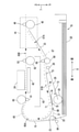
図1に示されるように、複合機10は、薄型の直方体に概ね形成されており、下部にイ
ンクジェット記録方式のプリンタ部11が設けられている。複合機10は、ファクシミリ
機能及びプリント機能などの各種の機能を有している。プリント機能としては、記録用紙
の両面に画像を記録する両面画像記録機能を有している。なお、プリント機能以外の機能
の有無は任意である。プリンタ部11は、正面に開口13が形成されたケーシング(筐体
)14を有し、各種サイズの記録用紙(本発明のシートの一例)を載置可能なトレイ20
(本発明のトレイの一例)を備えた給紙カセット78が、開口13から前後方向8に挿抜
可能である。複合機10の正面上部には、操作パネル17が設けられている。操作パネル
17は、プリンタ部11を操作するための装置である。複合機10は、操作パネル17か
らの操作入力に基づいて動作する。
As shown in FIG. 1, the multifunction device 10 is generally formed in a thin rectangular parallelepiped, and an inkjet recording type printer unit 11 is provided at the lower portion. The multifunction device 10 has various functions such as a facsimile function and a print function. As a printing function, it has a double-sided image recording function for recording an image on both sides of a recording paper. The presence or absence of a function other than the print function is arbitrary. The printer unit 11 has a casing (housing) 14 having an opening 13 formed in the front surface thereof, and a tray 20 on which recording papers of various sizes (an example of a sheet of the present invention) can be placed.
A paper cassette 78 provided with (an example of a tray of the present invention) can be inserted and removed from the opening 13 in the front-rear direction 8. An operation panel 17 is provided on the upper part of the front surface of the multifunction device 10. The operation panel 17 is a device for operating the printer unit 11. The multifunction device 10 operates based on the operation input from the operation panel 17.

[プリンタ部11の構成]
次に、図2が参照されながら、プリンタ部11の構成が説明される。なお、図2では、
給紙カセット78の前方側(紙面右側)の図示が省略されている。プリンタ部11は、ト
レイ20から記録用紙をピックアップして給紙(給送)する給紙部15(本発明の給紙部
の一例)と、給紙部15によって給紙された記録用紙にインク滴を吐出して記録用紙に画
像を記録するインクジェット記録方式の記録部24(本発明の記録部の一例)と、経路切
換部41などを備えている。なお、記録部24はインクジェット方式に限られず、電子写
真方式などの種々の記録方式のものが適用可能である。
[Configuration of printer unit 11]
Next, the configuration of the printer unit 11 will be described with reference to FIG. 2. In addition, in FIG. 2,
The front side (right side of the paper) of the paper cassette 78 is not shown. The printer unit 11 picks up the recording paper from the tray 20 and feeds (feeds) the paper to the paper feeding unit 15 (an example of the paper feeding unit of the present invention) and the recording paper fed by the paper feeding unit 15 with ink. It is provided with an inkjet recording type recording unit 24 (an example of a recording unit of the present invention) for ejecting drops and recording an image on recording paper, a route switching unit 41, and the like. The recording unit 24 is not limited to the inkjet method, and various recording methods such as an electrophotographic method can be applied.

[搬送路65]
プリンタ部11の内部には、トレイ20の先端(後方側の端部)から記録部24を経て
排紙保持部79に至る搬送路65が形成されている。搬送路65は、トレイ20の先端か
ら記録部24に至る間に形成された湾曲路65A(本発明の第1搬送路の一例)と、記録
部24から排紙保持部79に至る間に形成された排紙路65Bとに区分される。湾曲路6
5Aは、トレイ20に設けられた分離傾斜板22(本発明の傾斜板の一例)の上端付近か
ら記録部24に渡って延設された湾曲状の通路である。
[Transport path 65]
Inside the printer unit 11, a transport path 65 is formed from the tip end (rear end portion) of the tray 20 to the paper ejection holding unit 79 via the recording unit 24. The transport path 65 is formed between a curved path 65A (an example of the first transport path of the present invention) formed between the tip of the tray 20 and the recording unit 24, and between the recording unit 24 and the paper ejection holding unit 79. It is classified into the output paper path 65B. Curved road 6
Reference numeral 5A is a curved passage extending from the vicinity of the upper end of the separation inclined plate 22 (an example of the inclined plate of the present invention) provided on the tray 20 to the recording unit 24.

分離傾斜板22は、トレイ20の後端部において左右方向9(図2の紙面に垂直な方向
)に渡って後方斜め上方に延設されている。分離傾斜板22とトレイ20におけるシート
載置面とがなす角の角度は、シート載置面に載置された記録用紙が湾曲路へ円滑に導かれ
る角度である。例えば、分離傾斜板22とシート載置面とがなす角の角度は、シート載置
面と平行な直線と湾曲路65Aの始端64からの延長戦がなす角の角度の2分の1の角度
に設定される。以上より、分離傾斜板22は、シート載置面から湾曲路65Aへの記録用
紙の搬送向きに沿ってトレイ20と一体に設けられ、シート載置面と湾曲路65Aとがな
す角を緩和する角度の傾斜を構成する。
The separation inclined plate 22 extends diagonally upward to the rear in the left-right direction 9 (direction perpendicular to the paper surface of FIG. 2) at the rear end of the tray 20. The angle between the separation inclined plate 22 and the sheet mounting surface on the tray 20 is an angle at which the recording paper mounted on the sheet mounting surface is smoothly guided to the curved path. For example, the angle between the separation inclined plate 22 and the seat mounting surface is half the angle between the straight line parallel to the seat mounting surface and the angle formed by the extended battle from the starting end 64 of the curved path 65A. Is set to. From the above, the separation inclined plate 22 is provided integrally with the tray 20 along the direction in which the recording paper is conveyed from the sheet mounting surface to the curved path 65A, and the angle formed by the sheet mounting surface and the curved path 65A is relaxed. Consists of an angle tilt.

湾曲路65Aは、プリンタ部11の内部側を中心とする円弧形状に概ね形成されている
。トレイ20から給送される記録用紙は、湾曲路65Aを介して、記録部24へ案内され
る。湾曲路65Aは、所定間隔を隔てて互いに対向する外側ガイド部材18と内側ガイド
部材19とによって区画されている。つまり、外側ガイド部材18と内側ガイド部材19
は、本発明の第1ガイド部材の一例である。なお、外側ガイド部材18及び内側ガイド部
材19、更に後述する上側ガイド部材82、下側ガイド部材83、上側傾斜ガイド部材3
2、下側傾斜ガイド部材33、及び支持部材43は、いずれも、図2の紙面垂直方向(図
1の左右方向9)へ延出されている。
The curved path 65A is generally formed in an arc shape centered on the inner side of the printer unit 11. The recording paper supplied from the tray 20 is guided to the recording unit 24 via the curved path 65A. The curved path 65A is partitioned by an outer guide member 18 and an inner guide member 19 facing each other at predetermined intervals. That is, the outer guide member 18 and the inner guide member 19
Is an example of the first guide member of the present invention. The outer guide member 18, the inner guide member 19, the upper guide member 82, the lower guide member 83, and the upper inclined guide member 3 which will be described later.
2. The lower inclined guide member 33 and the support member 43 all extend in the direction perpendicular to the paper surface in FIG. 2 (left-right direction 9 in FIG. 1).

なお、本実施形態において、外側ガイド部材18は、図4に示されるように、基軸84
を中心として矢印85の方向に回動する。当該回動は、例えば複合機10のユーザの手動
によって行われる。
In this embodiment, the outer guide member 18 has a base shaft 84 as shown in FIG.
Rotates in the direction of arrow 85 about the center. The rotation is performed manually, for example, by the user of the multifunction device 10.

排紙路65Bは、記録部24よりも第1搬送向きの下流側から排紙保持部79に渡って
延設された直線上の通路である。ここで、第1搬送向きとは、記録用紙が搬送路65を搬
送される向き(図2において矢印付きの一点鎖線で示される向き)を指す。
The paper discharge path 65B is a straight passage extending from the downstream side of the recording unit 24 toward the first transport to the paper discharge holding unit 79. Here, the first transport direction refers to the direction in which the recording paper is transported along the transport path 65 (the orientation indicated by the alternate long and short dash line with an arrow in FIG. 2).

記録部24よりも第1搬送向きの下流側に分岐口36が形成されている。両面画像記録
の際には、排紙路65Bを搬送される記録用紙は、分岐口36の下流側でスイッチバック
され、後述する反転搬送路67(本発明の第2搬送路の一例)へ向けて搬送される。
A branch port 36 is formed on the downstream side of the recording unit 24 in the direction of the first transport. At the time of double-sided image recording, the recording paper conveyed through the paper ejection path 65B is switched back on the downstream side of the branch port 36 and directed toward the inverted transfer path 67 (an example of the second transport path of the present invention) described later. Will be transported.

[記録部24]
記録部24は、トレイ20の上方に配置されている。記録部24は、図2の紙面垂直方
向(主走査方向)に往復動する。記録部24の下方には記録用紙を水平に保持するための
プラテン42が設けられている。記録部24は、主走査方向への往復移動過程において、
図示しないインクカートリッジから供給されたインクをノズル39からプラテン42上を
搬送される記録用紙に吐出する。これにより、記録用紙に画像が記録される。
[Recording unit 24]
The recording unit 24 is arranged above the tray 20. The recording unit 24 reciprocates in the direction perpendicular to the paper surface (main scanning direction) in FIG. A platen 42 for holding the recording paper horizontally is provided below the recording unit 24. The recording unit 24 is in the process of reciprocating in the main scanning direction.
Ink supplied from an ink cartridge (not shown) is ejected from the nozzle 39 onto the recording paper conveyed on the platen 42. As a result, the image is recorded on the recording paper.

湾曲路65Aの終端と記録部24との間には、第1搬送ローラ60及びピンチローラ6
1が設けられている。ピンチローラ61は、図示しないバネなどの弾性部材によって第1
搬送ローラ60のローラ面に圧接されている。第1搬送ローラ60及びピンチローラ61
は、湾曲路65Aを搬送してきた記録用紙を狭持してプラテン42上へ送る。また、記録
部24と排紙路65Bの始端との間には、第2搬送ローラ62及び拍車ローラ63が設け
られている。ピンチローラ61と同様、拍車ローラ63は第2搬送ローラ62のローラ面
に圧接されている。第2搬送ローラ62及び拍車ローラ63は、記録部24によって画像
を記録された記録用紙を狭持して第1搬送向きの下流側(排紙保持部79側)へ搬送する
A first transfer roller 60 and a pinch roller 6 are located between the end of the curved path 65A and the recording unit 24.
1 is provided. The pinch roller 61 is first formed by an elastic member such as a spring (not shown).
It is pressed against the roller surface of the transport roller 60. First transport roller 60 and pinch roller 61
Holds the recording paper conveyed on the curved road 65A and sends it onto the platen 42. Further, a second transport roller 62 and a spur roller 63 are provided between the recording unit 24 and the start end of the paper discharge path 65B. Like the pinch roller 61, the spur roller 63 is pressed against the roller surface of the second transfer roller 62. The second transfer roller 62 and the spur roller 63 hold the recording paper on which the image is recorded by the recording unit 24 and transfer it to the downstream side (paper ejection holding unit 79 side) facing the first transfer.

第1搬送ローラ60及び第2搬送ローラ62は、搬送用モータ(不図示)から駆動伝達
機構(不図示)を介して回転駆動力が伝達されて回転される。駆動伝達機構は、遊星ギヤ
などから構成されており、搬送用モータが正転または逆転のいずれに回転されても、記録
用紙を第1搬送向きへ搬送させるべく、第1搬送ローラ60及び第2搬送ローラ62を一
回転方向へ回転させる。
The first transfer roller 60 and the second transfer roller 62 are rotated by transmitting a rotational driving force from a transfer motor (not shown) via a drive transmission mechanism (not shown). The drive transmission mechanism is composed of planetary gears and the like, and regardless of whether the transfer motor is rotated in the forward or reverse direction, the first transfer roller 60 and the second transfer roller 60 and the second transfer roller are used to transfer the recording paper in the first transfer direction. The transport roller 62 is rotated in one rotation direction.

[給紙部15]
給紙部15は、記録部24の下方であってトレイ20の上方、つまり記録部24とトレ
イ20の間に設けられている。給紙部15は、トレイ20に収容された記録用紙を湾曲路
65Aへ向けて搬送する。給紙部15は、給紙ローラ25(本発明のローラの一例)と、
給紙アーム26(本発明のアームの一例)と、駆動伝達機構27とを備えている。
[Paper feed unit 15]
The paper feed unit 15 is provided below the recording unit 24 and above the tray 20, that is, between the recording unit 24 and the tray 20. The paper feed unit 15 conveys the recording paper stored in the tray 20 toward the curved path 65A. The paper feed unit 15 includes a paper feed roller 25 (an example of a roller of the present invention) and a paper feed roller 25.
It includes a paper feed arm 26 (an example of an arm of the present invention) and a drive transmission mechanism 27.

給紙ローラ25は、トレイ20に載置されている記録用紙をピックアップして湾曲路6
5Aへ給紙するものであり、給紙アーム26の先端に回転自在に軸支されている。給紙ロ
ーラ25は、搬送用モータとは異なる駆動源のASF(Auto Sheet Feed)モータ(不図示
)から駆動伝達機構27を介して回転力が伝達されると回転駆動される。駆動伝達機構2
7は給紙アーム26に軸支されており、概ね直線状に並ぶ複数のギヤで構成されている。
ASFモータは、正転又は逆転の一方に回転され、給紙ローラ25は、ASFモータの回
転により、記録用紙を湾曲路65Aへ給紙する向きに回転する。
The paper feed roller 25 picks up the recording paper placed on the tray 20 and the curved path 6
The paper is fed to 5A, and is rotatably supported by the tip of the paper feed arm 26. The paper feed roller 25 is rotationally driven when a rotational force is transmitted from an ASF (Auto Sheet Feed) motor (not shown), which is a drive source different from the transport motor, via a drive transmission mechanism 27. Drive transmission mechanism 2
Reference numeral 7 is pivotally supported by the paper feed arm 26, and is composed of a plurality of gears arranged substantially linearly.
The ASF motor is rotated in either forward or reverse rotation, and the paper feed roller 25 is rotated in the direction of feeding the recording paper to the curved path 65A by the rotation of the ASF motor.

給紙アーム26は、その基端部が基軸28に支持されており、基軸28を中心軸として
回動可能である。このため、給紙アーム26は、トレイ20に対して接離可能に上下動す
ることができる。また、給紙アーム26は、自重により又はバネなどの弾性部材による弾
性力により、図2の矢印29の方向へ回動付勢されている。このため、給紙ローラ25は
、トレイ20に収容された記録用紙の上面に圧接可能である。つまり、給紙部15は、給
紙ローラ25がトレイ20における記録用紙が載置されている面(本発明のシート載置面
に相当。以下、シート載置面と記す。)に当接する第1姿勢(本発明の第1姿勢に相当)
をとる。
The base end of the paper feed arm 26 is supported by the base shaft 28, and the paper feed arm 26 can rotate around the base shaft 28. Therefore, the paper feed arm 26 can move up and down so as to be in contact with and detach from the tray 20. Further, the paper feed arm 26 is rotationally urged in the direction of the arrow 29 in FIG. 2 by its own weight or by an elastic force of an elastic member such as a spring. Therefore, the paper feed roller 25 can be pressed against the upper surface of the recording paper housed in the tray 20. That is, in the paper feed unit 15, the paper feed roller 25 comes into contact with the surface of the tray 20 on which the recording paper is placed (corresponding to the sheet mounting surface of the present invention; hereinafter referred to as the sheet mounting surface). 1 posture (corresponding to the first posture of the present invention)
Take.

また、図5及び図6に示されるように、給紙部15は、トレイ20がプリンタ部11に
対して挿入される際、またはトレイ20がプリンタ部11から引き抜かれる際に、トレイ
20の上面(例えば分離傾斜板22)に押されることによって、上方へ押し上げられる。
つまり、給紙部15は、トレイ20が複合機10に対して挿抜される過程において、分離
傾斜板22により上方へ押されることによって、シート載置面から離間してトレイ20の
挿抜領域から退避する第5姿勢(本発明の第5姿勢に相当)に回動可能である。
Further, as shown in FIGS. 5 and 6, the paper feeding unit 15 is the upper surface of the tray 20 when the tray 20 is inserted into the printer unit 11 or when the tray 20 is pulled out from the printer unit 11. By being pushed by (for example, the separation inclined plate 22), it is pushed upward.
That is, the paper feed unit 15 is pushed upward by the separation inclined plate 22 in the process of inserting and removing the tray 20 from the multifunction device 10, so that the tray 20 is separated from the sheet mounting surface and retracted from the insertion / removal area of the tray 20. It is rotatable to the fifth posture (corresponding to the fifth posture of the present invention).

なお、給紙部15を押すのは、分離傾斜板22に限らない。例えば、トレイ20の側壁
21(図2参照)であってもよいし、トレイ20の側壁21及び分離傾斜板22の双方で
あってもよい。
It should be noted that pushing the paper feed unit 15 is not limited to the separation inclined plate 22. For example, it may be the side wall 21 of the tray 20 (see FIG. 2), or it may be both the side wall 21 of the tray 20 and the separation inclined plate 22.

また、上述したように、給紙アーム26は、図2の矢印29の方向へ回動付勢されてい
る。そのため、図4に示されるように、給紙部15は、トレイ20がプリンタ部11から
引き抜かれた状態では、トレイ20の下方に配置されている複合機10のフレーム77な
どに圧接される。つまり、給紙部15は、トレイ20が複合機10から抜かれた状態にお
いて、給紙ローラ25が第1姿勢よりも下方となる第2姿勢(本発明の第2姿勢に相当)
へ回動可能である。以上より、給紙アーム26は、第1姿勢、第5姿勢、及び第2姿勢と
の間で回動する。
Further, as described above, the paper feed arm 26 is rotationally urged in the direction of the arrow 29 in FIG. Therefore, as shown in FIG. 4, the paper feeding unit 15 is pressed against the frame 77 of the multifunction device 10 arranged below the tray 20 when the tray 20 is pulled out from the printer unit 11. That is, the paper feed unit 15 has a second posture (corresponding to the second posture of the present invention) in which the paper feed roller 25 is lower than the first posture when the tray 20 is pulled out from the multifunction device 10.
It is rotatable to. From the above, the paper feed arm 26 rotates between the first posture, the fifth posture, and the second posture.

[経路切換部41]
図2に示されるように、経路切換部41は、搬送路65における分岐口36付近に配置
されている。経路切換部41は、第3搬送ローラ45と、拍車ローラ46と、フラップ4
9で構成されている。
[Route switching unit 41]
As shown in FIG. 2, the route switching unit 41 is arranged near the branch port 36 in the transport path 65. The route switching unit 41 includes a third transport roller 45, a spur roller 46, and a flap 4.
It is composed of 9.

第3搬送ローラ45は、下側ガイド部材83よりも下流側に設けられている。第3搬送
ローラ45は、プリンタ部11のフレームなどに回転可能に支持されている。拍車ローラ
46は、自重若しくはバネなどによって第3搬送ローラ45のローラ面に圧接されている
The third transport roller 45 is provided on the downstream side of the lower guide member 83. The third transfer roller 45 is rotatably supported by a frame or the like of the printer unit 11. The spur roller 46 is pressed against the roller surface of the third transport roller 45 by its own weight or a spring.

第3搬送ローラ45は、搬送用モータから正逆回転方向の駆動力が伝達されて、正逆転
いずれかの方向に回転される。例えば、片面記録が行われる場合は、第3搬送ローラ45
は正転方向へ回転される。これにより、記録用紙は第3搬送ローラ45及び拍車ローラ4
6に挟持されて下流側へ搬送され、排紙保持部79に排紙される。一方、両面記録が行わ
れる場合は、第3搬送ローラ45及び拍車ローラ46が記録用紙の後端部を挟持した状態
で、第3搬送ローラ45の回転方向が正転から逆転へ切り換えられる。
The third transfer roller 45 is rotated in either the forward or reverse direction by transmitting the driving force in the forward / reverse rotation direction from the transfer motor. For example, when single-sided recording is performed, the third transport roller 45
Is rotated in the forward rotation direction. As a result, the recording paper becomes the third transport roller 45 and the spur roller 4.
It is sandwiched between 6 and transported to the downstream side, and is discharged to the paper discharge holding unit 79. On the other hand, when double-sided recording is performed, the rotation direction of the third transport roller 45 is switched from normal rotation to reverse rotation with the third transport roller 45 and the spur roller 46 sandwiching the rear end portion of the recording paper.

図2の紙面垂直方向(図1の左右方向9)へ延びる支軸87が、プリンタ部11のフレ
ームなどに設けられている。フラップ49は、支軸87から概ね下流側へ延出されている
。フラップ49は、支軸87に回動可能に軸支されている。フラップ49には、拍車状に
形成された補助ローラ47及び補助ローラ48が軸支されている。
A support shaft 87 extending in the vertical direction of the paper surface (9 in the left-right direction of FIG. 1) of FIG. 2 is provided on the frame of the printer unit 11 or the like. The flap 49 extends substantially downstream from the support shaft 87. The flap 49 is rotatably supported by a support shaft 87. An auxiliary roller 47 and an auxiliary roller 48 formed in a spur shape are pivotally supported by the flap 49.

フラップ49は、姿勢変化可能に構成されており、下側ガイド部材83よりも上方に位
置する排出姿勢(図2に破線で示される姿勢)と、延出端部49Aが分岐口36よりも下
方へ進入する反転姿勢(図2に実線で示される姿勢)との間で回動する。記録部24を通
過した記録用紙は、フラップ49が排出姿勢の場合、更に第1搬送向きの下流側へ搬送さ
れ、フラップ49が反転姿勢の場合、反転搬送路67へスイッチバック搬送される。
The flap 49 is configured so that the posture can be changed, and the discharge posture (the posture shown by the broken line in FIG. 2) located above the lower guide member 83 and the extension end portion 49A are below the branch port 36. Rotates between the inverted posture (the posture shown by the solid line in FIG. 2) and the inverted posture (the posture shown by the solid line in FIG. 2). The recording paper that has passed through the recording unit 24 is further transported to the downstream side in the first transport direction when the flap 49 is in the discharge posture, and is switched back to the reverse transport path 67 when the flap 49 is in the reverse posture.

[反転搬送路67]
反転搬送路67は、搬送路65における記録部24より第1搬送向きの下流側から搬送
路65における第1搬送ローラ60より第1搬送向きの上流側へ記録用紙を案内する。反
転搬送路67は、分岐口36で排紙路65Bから分岐され、記録部24と給紙アーム27
の間を通って、記録部24よりも第1搬送向きの上流側の合流部37で湾曲路65Aと合
流する。記録用紙は、反転搬送路67を第2搬送向きに搬送される。ここで、第2搬送向
きとは、図2における矢印付きの二点鎖線で示される向きを指す。以上より、反転搬送路
67は、記録部24によって少なくとも一方の面に画像が記録された記録用紙を湾曲路6
5Aへ案内するための経路である。
[Reversal transport path 67]
The reverse transfer path 67 guides the recording paper from the downstream side of the recording unit 24 in the transfer path 65 toward the first transfer to the upstream side of the first transfer roller 60 in the transfer path 65 toward the first transfer. The reverse transfer path 67 is branched from the paper discharge path 65B at the branch port 36, and the recording unit 24 and the paper feed arm 27 are branched.
It merges with the curved road 65A at the confluence 37 on the upstream side of the recording unit 24 in the direction of the first transport. The recording paper is conveyed along the reverse transfer path 67 in the second transfer direction. Here, the second transport direction refers to the direction indicated by the two-dot chain line with an arrow in FIG. From the above, the reversing transport path 67 is a curved path 6 for recording paper on which an image is recorded on at least one surface by the recording unit 24.
This is a route to guide you to 5A.

反転搬送路67は、第1経路67Aと第2経路67Bとに区分される。第1経路67A
は、分岐口36から後方斜め下向きに傾斜する傾斜面を有する上側傾斜ガイド部材32と
下側傾斜ガイド部材33とによって区画されている。
The reverse transport path 67 is divided into a first path 67A and a second path 67B. First route 67A
Is partitioned by an upper inclined guide member 32 having an inclined surface inclined backward and diagonally downward from the branch port 36 and a lower inclined guide member 33.

第2経路67Bは、図5及び図6の矢印30,34に示す方向に回動可能に支持された
回動ガイド部材70(本発明の第2ガイド部材の一例)と、プリンタ部11のフレームに
取り付けられており、記録部24を支持している支持部材43とによって区画されている
The second path 67B includes a rotation guide member 70 (an example of the second guide member of the present invention) rotatably supported in the directions shown by arrows 30 and 34 in FIGS. 5 and 6, and a frame of the printer unit 11. It is attached to and is partitioned by a support member 43 that supports the recording unit 24.

反転搬送路67には、第4搬送ローラ68及び拍車ローラ69が設けられている。拍車
ローラ69は、自重若しくはバネなどによって第4搬送ローラ68のローラ面に圧接され
ている。第4搬送ローラ68は、回転することによって記録用紙を第2搬送向きへ搬送す
る。第4搬送ローラ68は、搬送用モータから回転力が伝達されて回転駆動される。第4
搬送ローラ68の回転の向きは、記録用紙を第2搬送向きへ搬送させる向きである。
The reversing transport path 67 is provided with a fourth transport roller 68 and a spur roller 69. The spur roller 69 is pressed against the roller surface of the fourth transport roller 68 by its own weight or a spring. The fourth transport roller 68 rotates to transport the recording paper in the second transport direction. The fourth transfer roller 68 is rotationally driven by transmitting a rotational force from the transfer motor. Fourth
The direction of rotation of the transfer roller 68 is the direction in which the recording paper is conveyed in the second transfer direction.

[回動ガイド部材70]
回動ガイド部材70は、記録部24と給紙部15の間に設けられている。回動ガイド部
材70は、上下方向7の寸法が前後方向8及び左右方向9の寸法よりも短い概ね薄型の平
板矩形状の部材である。回動ガイド部材70は、その先端部(後方側の端部)が斜め上向
きに湾曲している。これにより、反転搬送路67及び湾曲路65Aは略円弧状の経路を構
成し、反転搬送路67を搬送される記録用紙は湾曲路65Aに円滑に導かれる。
[Rotating guide member 70]
The rotation guide member 70 is provided between the recording unit 24 and the paper feeding unit 15. The rotation guide member 70 is a substantially thin flat plate rectangular member whose dimensions in the vertical direction 7 are shorter than those in the front-rear direction 8 and the horizontal direction 9. The tip of the rotation guide member 70 (the end on the rear side) is curved diagonally upward. As a result, the reversing transport path 67 and the curved path 65A form a substantially arcuate path, and the recording paper conveyed on the reversing transport path 67 is smoothly guided to the curved path 65A.

回動ガイド部材70は、その基端部(前方側の端部)が給紙部15の基軸73に支持さ
れており、基軸73を中心軸として回動可能である。基軸73に支持されることにより、
回動ガイド部材70は、記録部24に対して接近及び離間可能に上下動することができる
The base end portion (front end portion) of the rotation guide member 70 is supported by the base shaft 73 of the paper feed unit 15, and the rotation guide member 70 can rotate around the base shaft 73. By being supported by the base shaft 73
The rotation guide member 70 can move up and down so as to be able to approach and separate from the recording unit 24.

回動ガイド部材70は、回動することによって、反転搬送路67の少なくとも一部を形
成する第3姿勢(本発明の第3姿勢に相当)と、第3姿勢よりも記録部24側へ接近する
第6姿勢(本発明の第6姿勢に相当)と、第3姿勢よりも記録部24側から離間する第4
姿勢(本発明の第4姿勢に相当)とをとることが可能である。
The rotation guide member 70 is closer to the recording unit 24 side than the third posture (corresponding to the third posture of the present invention) forming at least a part of the inverted transport path 67 by rotating. The sixth posture (corresponding to the sixth posture of the present invention) and the fourth posture that is farther from the recording unit 24 side than the third posture.
It is possible to take a posture (corresponding to the fourth posture of the present invention).

第3姿勢は、図2及び図3に示されるように、回動ガイド部材70の上面が支持部材4
3と記録用紙が通過可能な所定の間隔を保持する姿勢である。回動ガイド部材70が第3
姿勢をとっている場合、回動ガイド部材70はトレイ20の側壁21に支持されている。
トレイ20の側壁21は、記録用紙が載置される底板の左右方向9の両端部から前後方向
8に沿って立設されている。図2及び図3では、トレイ20の側壁21の上端部が破線で
示されている。なお、本実施形態では、回動ガイド部材70の下面から支持部材80が突
設されており、支持部材80と側壁21が当接されることで回動ガイド部材70は側壁2
1に支持されている。なお、図4から図6において、側壁21の図示は省略されている。
In the third posture, as shown in FIGS. 2 and 3, the upper surface of the rotation guide member 70 is the support member 4.
It is a posture that keeps a predetermined distance between 3 and the recording paper. The rotation guide member 70 is the third
When in the posture, the rotation guide member 70 is supported by the side wall 21 of the tray 20.
The side wall 21 of the tray 20 is erected along the front-rear direction 8 from both ends of the bottom plate on which the recording paper is placed in the left-right direction 9. In FIGS. 2 and 3, the upper end of the side wall 21 of the tray 20 is shown by a broken line. In the present embodiment, the support member 80 is projected from the lower surface of the rotation guide member 70, and the support member 80 and the side wall 21 are brought into contact with each other so that the rotation guide member 70 has the side wall 2.
It is supported by 1. In addition, in FIGS. 4 to 6, the illustration of the side wall 21 is omitted.

第6姿勢は、図6に示されるように、回動ガイド部材70の下面が給紙部15に押され
ることによって、回動ガイド部材70の上面が、支持部材43の近傍まで接近する姿勢で
ある。第4姿勢は、図4に示されるように、トレイ20が複合機10から抜かれた際に、
回動ガイド部材70の下面がトレイ20の側壁21に支持されなくなることによって、回
動ガイド部材70が、給紙部15の第2姿勢への回動に追随して、複合機10のフレーム
77の上方近傍まで接近する姿勢である。
In the sixth posture, as shown in FIG. 6, the lower surface of the rotation guide member 70 is pushed by the paper feed unit 15, so that the upper surface of the rotation guide member 70 approaches the vicinity of the support member 43. be. The fourth posture is, as shown in FIG. 4, when the tray 20 is pulled out from the multifunction device 10.
Since the lower surface of the rotation guide member 70 is no longer supported by the side wall 21 of the tray 20, the rotation guide member 70 follows the rotation of the paper feed unit 15 to the second posture, and the frame 77 of the multifunction device 10 It is a posture that approaches to the upper vicinity of.

[孔71]
回動ガイド部材70の記録用紙が搬送される面(本発明のシート搬送面に相当。以下、
シート搬送面と記す。)には、給紙ローラ25と対向する位置に開口が設けられている。
詳細には、図4に示されるように、回動ガイド部材70が第4姿勢をとっている場合に、
回動ガイド部材70に開口が設けられていないと給紙ローラ25の少なくとも一部(例え
ば、給紙ローラ25の給紙アーム26よりも上側のローラ表面)が回動ガイド部材70に
当接する位置に、第1の孔71(本発明の第1開口部の一例)が設けられている。
[Hole 71]
The surface on which the recording paper of the rotation guide member 70 is conveyed (corresponding to the sheet transfer surface of the present invention;
It is referred to as the sheet transport surface. ) Is provided with an opening at a position facing the paper feed roller 25.
Specifically, as shown in FIG. 4, when the rotation guide member 70 is in the fourth posture,
If the rotation guide member 70 is not provided with an opening, a position where at least a part of the paper feed roller 25 (for example, the roller surface above the paper feed arm 26 of the paper feed roller 25) abuts on the rotation guide member 70. Is provided with a first hole 71 (an example of the first opening of the present invention).

また、図5に示されるように、回動ガイド部材70が第3姿勢をとっている場合に、回
動ガイド部材70に開口が設けられていないと給紙ローラ25及び/または給紙アーム2
6の少なくとも一部(例えば、給紙ローラ25の給紙アーム26よりも上側のローラ面や
、給紙アーム26の上面)が回動ガイド部材70に当接する位置に、第2の孔(本発明の
第2開口部の一例)が設けられている。
Further, as shown in FIG. 5, when the rotation guide member 70 is in the third posture, if the rotation guide member 70 is not provided with an opening, the paper feed roller 25 and / or the paper feed arm 2
A second hole (mainly, at a position where at least a part of 6 (for example, a roller surface above the paper feed arm 26 of the paper feed roller 25 or an upper surface of the paper feed arm 26) abuts on the rotation guide member 70. An example of the second opening of the invention) is provided.

なお、本実施形態においては、第1の孔71と第2の孔は共用されており、同一の孔で
ある。しかし、回動ガイド部材70と給紙ローラ25の相対位置関係によっては、回動ガ
イド部材70が第4姿勢をとる場合と第3姿勢をとる場合とで、給紙ローラ25が回動ガ
イド部材70に当接する位置が異なる場合がある。その場合、第1の孔と第2の孔は別個
に設けられる。以下、第1の孔71と第2の孔が共用された孔は、単に孔71と記される
In this embodiment, the first hole 71 and the second hole are shared and are the same hole. However, depending on the relative positional relationship between the rotation guide member 70 and the paper feed roller 25, the paper feed roller 25 may take the rotation guide member depending on whether the rotation guide member 70 takes the fourth posture or the third posture. The position of contact with 70 may be different. In that case, the first hole and the second hole are provided separately. Hereinafter, the hole in which the first hole 71 and the second hole are shared is simply referred to as a hole 71.

回動ガイド部材70に孔71が設けられることにより、回動ガイド部材70が第4姿勢
の状態において、第2姿勢の給紙ローラ25の少なくとも一部が貫通して回動ガイド部材
70のシート搬送面より上方へ突出する。また、回動ガイド部材70が第3姿勢の状態に
おいて、第5姿勢に回動された給紙部15の少なくとも一部が貫通して回動ガイド部材7
0のシート搬送面より上方へ突出する。
By providing the hole 71 in the rotation guide member 70, at least a part of the paper feed roller 25 in the second posture penetrates the sheet of the rotation guide member 70 in the state where the rotation guide member 70 is in the fourth posture. It protrudes upward from the transport surface. Further, in the state where the rotation guide member 70 is in the third posture, at least a part of the paper feed unit 15 rotated in the fifth posture penetrates and the rotation guide member 7
It protrudes upward from the sheet transport surface of 0.

[突起72]
図3に示されるように、給紙アーム26の上面の給紙ローラ25との近傍部分には、突
起72が設けられている。図6に示されるように、突起72(本発明のストッパの一例)
は、給紙部15が第5姿勢をとっている場合に、回動ガイド部材70の下面と当接してい
る。なお、突起72が設けられる位置は、給紙部15の回動による給紙ローラ25の表面
と回動ガイド部材70との接触が防止可能であれば、給紙アーム26の上面に限らない。
[Protrusion 72]
As shown in FIG. 3, a protrusion 72 is provided on the upper surface of the paper feed arm 26 in the vicinity of the paper feed roller 25. As shown in FIG. 6, the protrusion 72 (an example of the stopper of the present invention)
Is in contact with the lower surface of the rotation guide member 70 when the paper feed unit 15 is in the fifth posture. The position where the protrusion 72 is provided is not limited to the upper surface of the paper feed arm 26 as long as the contact between the surface of the paper feed roller 25 and the rotation guide member 70 due to the rotation of the paper feed unit 15 can be prevented.

[板状部材75]
図3に示されるように、回動ガイド部材70の下面における孔71の基軸73側の端部
近傍の位置に基軸74が設けられている。また、孔71と略同一形状をした板状部材75
(本発明の開閉部材の一例)が、孔71を塞ぐ位置に設けられている。板状部材75は、
その基端部が基軸74に支持されており、基軸74を中心軸として回動可能である。
[Plate-shaped member 75]
As shown in FIG. 3, the base shaft 74 is provided at a position near the end of the hole 71 on the base shaft 73 side on the lower surface of the rotation guide member 70. Further, a plate-shaped member 75 having substantially the same shape as the hole 71.
(An example of the opening / closing member of the present invention) is provided at a position to close the hole 71. The plate-shaped member 75 is
The base end portion is supported by the base shaft 74, and is rotatable around the base shaft 74.

板状部材75は、自重により又はバネなどの弾性部材による弾性力により、下方に回動
付勢されている。但し、規制部材(不図示)などによって、孔71を塞ぐ位置(図3に示
される位置)より下方には回動されないように構成されている。これにより、図3に示さ
れるように、板状部材75は、給紙部15が第1姿勢をとっている場合、孔71を閉鎖す
る位置に回動される。その結果、板状部材75は、回動ガイド部材70のシート搬送面の
一部を形成する。一方、図6に示されるように、板状部材75は、給紙部15が第5姿勢
をとっている場合、給紙ローラ25の表面に押され、孔71を開放する位置に回動される
The plate-shaped member 75 is rotationally urged downward by its own weight or by an elastic force of an elastic member such as a spring. However, it is configured so as not to be rotated below the position (position shown in FIG. 3) that closes the hole 71 by a regulating member (not shown) or the like. As a result, as shown in FIG. 3, the plate-shaped member 75 is rotated to a position where the hole 71 is closed when the paper feeding unit 15 is in the first posture. As a result, the plate-shaped member 75 forms a part of the sheet transport surface of the rotation guide member 70. On the other hand, as shown in FIG. 6, when the paper feed unit 15 is in the fifth posture, the plate-shaped member 75 is pushed by the surface of the paper feed roller 25 and rotated to a position where the hole 71 is opened. To.

図3及び図6に基づく上述の説明では、給紙ローラ25のみが孔71を貫通する構成に
おいて板状部材75が設けられている場合について説明した。しかし、板状部材75は、
給紙ローラ25だけでなく給紙アーム26を含む給紙部15の少なくとも一部が孔71を
貫通する場合に設けられてもよい。この場合、板状部材75は、給紙アーム26を含む給
紙部15の少なくとも一部が貫通する孔71を塞ぐ位置及び開放する位置に姿勢変化する
ことが可能に構成される。
In the above description based on FIGS. 3 and 6, a case where the plate-shaped member 75 is provided in a configuration in which only the paper feed roller 25 penetrates the hole 71 has been described. However, the plate-shaped member 75 is
It may be provided when not only the paper feed roller 25 but also at least a part of the paper feed unit 15 including the paper feed arm 26 penetrates the hole 71. In this case, the plate-shaped member 75 is configured to be able to change its posture to a position where at least a part of the paper feed unit 15 including the paper feed arm 26 penetrates and a position where the hole 71 is opened.

なお、板状部材75は、回動されることによって孔71を塞ぐ位置と開放する位置に姿
勢変化するものに限らない。例えば、板状部材75は、回動ガイド部材70のシート搬送
面と平行にスライドされることによって姿勢変化するものであってもよい。
The plate-shaped member 75 is not limited to the one whose posture changes between the position where the hole 71 is closed and the position where the hole 71 is opened by being rotated. For example, the plate-shaped member 75 may change its posture by sliding in parallel with the sheet transport surface of the rotation guide member 70.

[弾性部材]
図4に示されるように、回動ガイド部材70の下面(シート搬送面の反対側の面)には
バネなどの弾性部材76(本発明の弾性部材の一例)が設けられている。図4に示される
ように、弾性部材76は、回動ガイド部材70が第4姿勢をとった場合に、最も下方に位
置する部分に設けられている。そして、回動ガイド部材70が第4姿勢をとった場合に、
弾性部材76は複合機10のフレーム77に当接される。なお、図4以外では、弾性部材
76の図示が省略されている。
[Elastic member]
As shown in FIG. 4, an elastic member 76 (an example of the elastic member of the present invention) such as a spring is provided on the lower surface of the rotation guide member 70 (the surface opposite to the sheet transport surface). As shown in FIG. 4, the elastic member 76 is provided at a portion located at the lowermost position when the rotation guide member 70 takes the fourth posture. Then, when the rotation guide member 70 takes the fourth posture,
The elastic member 76 is in contact with the frame 77 of the multifunction device 10. Other than FIG. 4, the elastic member 76 is not shown.

[給紙部15及び回動ガイド部材70の回動]
図3に示されるように、記録用紙に画像が記録される処理が実行されているとき、給紙
部15は第1姿勢をとっており、回動ガイド部材70は第3姿勢をとっている。上記処理
が実行されていないときに、トレイ20が複合機10から抜かれる過程において、回動ガ
イド部材70は、給紙部15の第1姿勢から第5姿勢への回動に連動して、第3姿勢から
第6姿勢へ回動される。その後、トレイ20が複合機10から抜かれると、給紙部15が
第5姿勢から第2姿勢へ回動され、回動ガイド部材70が第6姿勢から第4姿勢へ回動さ
れる。
[Rotation of the paper feed unit 15 and the rotation guide member 70]
As shown in FIG. 3, when the process of recording an image on the recording paper is being executed, the paper feed unit 15 is in the first posture, and the rotation guide member 70 is in the third posture. .. In the process in which the tray 20 is pulled out from the multifunction device 10 when the above process is not executed, the rotation guide member 70 is interlocked with the rotation of the paper feed unit 15 from the first posture to the fifth posture. It is rotated from the third posture to the sixth posture. After that, when the tray 20 is pulled out from the multifunction device 10, the paper feeding unit 15 is rotated from the fifth posture to the second posture, and the rotation guide member 70 is rotated from the sixth posture to the fourth posture.

以下に詳述する。図3に示される状態において、トレイ20がプリンタ部11から引き
抜かれる、つまり前方へ移動されると、分離傾斜板22の内側面23が給紙ローラ25に
当接しないように、給紙アーム26がトレイ20により上方へ回動し、それに伴い、給紙
ローラ25も上方へ回動する。よって、給紙部15が第1姿勢から第5姿勢へ回動する。
給紙ローラ25が所定量だけ上方へ回動すると、給紙ローラ25が板状部材75と当接す
る。
It will be described in detail below. In the state shown in FIG. 3, when the tray 20 is pulled out from the printer unit 11, that is, moved forward, the paper feed arm 26 is prevented from contacting the inner side surface 23 of the separation inclined plate 22 with the paper feed roller 25. Is rotated upward by the tray 20, and the paper feed roller 25 is also rotated upward accordingly. Therefore, the paper feed unit 15 rotates from the first posture to the fifth posture.
When the paper feed roller 25 rotates upward by a predetermined amount, the paper feed roller 25 comes into contact with the plate-shaped member 75.

この状態において、図5に示されるように、トレイ20が更に前方へ移動されることに
よって、給紙ローラ25が更に上方へ回動すると(図5の矢印30参照)、板状部材75
は給紙ローラ25に押されることによって上方へ回動する(図5の矢印31参照)。また
、突起72が回動ガイド部材70の下面に当接する。この状態において、給紙ローラ25
が更に上方へ回動すると(図6の矢印34参照)、回動ガイド部材70は、突起72に押
されることによって、給紙部15と一体に上方へ回動する(図6の矢印35参照)。つま
り、本実施形態においては、突起72が、給紙部15の第5姿勢への回動に連動させて回
動ガイド部材を第6姿勢へ回動させる本発明の連動部を構成している。
In this state, as shown in FIG. 5, when the tray 20 is further moved forward and the paper feed roller 25 is further rotated upward (see the arrow 30 in FIG. 5), the plate-shaped member 75
Is pushed upward by the paper feed roller 25 and rotates upward (see arrow 31 in FIG. 5). Further, the protrusion 72 abuts on the lower surface of the rotation guide member 70. In this state, the paper feed roller 25
Further upwards (see arrow 34 in FIG. 6), the rotation guide member 70 is pushed by the protrusion 72 and rotates upward integrally with the paper feed unit 15 (see arrow 35 in FIG. 6). ). That is, in the present embodiment, the protrusion 72 constitutes the interlocking portion of the present invention that rotates the rotation guide member to the sixth posture in conjunction with the rotation of the paper feed unit 15 to the fifth posture. ..

上記の回動は、図6に示されるように、給紙ローラ25が、分離傾斜板の上端と当接す
るまで継続される。図6の状態では、給紙部15は第5姿勢をとっており、回動ガイド部
材70は第6姿勢をとっている。
As shown in FIG. 6, the above rotation is continued until the paper feed roller 25 comes into contact with the upper end of the separation inclined plate. In the state of FIG. 6, the paper feeding unit 15 is in the fifth posture, and the rotation guide member 70 is in the sixth posture.

図6において、給紙部15は実線で第5姿勢の状態が示されている。一方、回動ガイド
部材70は破線で第3姿勢の状態が示されている。図6から明らかなとおり、給紙部15
は、回動ガイド部材70を上方へ押すことによって、それまで第5姿勢をとっていた回動
ガイド部材70が存在していた領域で第3姿勢をとる。つまり、給紙部15が第5姿勢を
とるための領域と、回動ガイド部材70が第3姿勢をとるための領域とは重なっている。
In FIG. 6, the paper feed unit 15 is shown in the fifth posture by a solid line. On the other hand, the rotation guide member 70 is shown in the third posture by the broken line. As is clear from FIG. 6, the paper feed unit 15
Pushes the rotation guide member 70 upward to take a third posture in the region where the rotation guide member 70, which had previously taken the fifth posture, was present. That is, the region for the paper feed unit 15 to take the fifth posture and the region for the rotation guide member 70 to take the third posture overlap.

また、図6に示されるように、第5姿勢の給紙部15の給紙アーム26は、その長手方
向(前後方向8)が第6姿勢の回動ガイド部材70のシート搬送面と略平行となるように
配置されている。
Further, as shown in FIG. 6, the paper feed arm 26 of the paper feed unit 15 in the fifth posture is substantially parallel to the sheet transport surface of the rotation guide member 70 in the sixth posture in its longitudinal direction (front-back direction 8). It is arranged so as to be.

図6の状態において、トレイ20が複合機10から完全に引き抜かれると、給紙部15
はトレイ20及び分離傾斜板22によって支持されていない状態となる。すると、図2の
矢印29の方向へ回動付勢されている給紙部15は、下方へ移動される。この際、図4に
示されるように、給紙ローラ25の下面は、それまで存在していたトレイ20のシート載
置面の高さよりも更に低い位置である第2姿勢に回動される。
In the state of FIG. 6, when the tray 20 is completely pulled out from the multifunction device 10, the paper feed unit 15
Is not supported by the tray 20 and the separation inclined plate 22. Then, the paper feed unit 15 that is urged to rotate in the direction of the arrow 29 in FIG. 2 is moved downward. At this time, as shown in FIG. 4, the lower surface of the paper feed roller 25 is rotated to the second posture, which is a position lower than the height of the sheet mounting surface of the tray 20 that has existed until then.

[実施形態の効果]
回動ガイド部材70は、トレイ20が複合機10から抜かれると第4姿勢に回動される
。これにより、記録部24と回動ガイド部材70の間の空間が大きくなる。したがって、
外側ガイド部材18が複合機10に対して開閉可能に構成されることにより、回動ガイド
部材70において記録用紙が詰まっても、記録用紙を容易に取り出すことができる。しか
し、上記のように回動ガイド部材70が第4姿勢に回動されると、給紙ローラ25へのア
クセスは回動ガイド部材70によって阻害される。
[Effect of embodiment]
The rotation guide member 70 is rotated to the fourth posture when the tray 20 is pulled out from the multifunction device 10. As a result, the space between the recording unit 24 and the rotation guide member 70 becomes large. therefore,
Since the outer guide member 18 is configured to be openable and closable with respect to the multifunction device 10, even if the recording paper is jammed in the rotation guide member 70, the recording paper can be easily taken out. However, when the rotation guide member 70 is rotated to the fourth posture as described above, access to the paper feed roller 25 is hindered by the rotation guide member 70.

しかし、上述の実施形態によれば、回動ガイド部材70に孔71が設けられている。そ
して、回動ガイド部材70が第4姿勢に回動されると、給紙ローラ25の少なくとも一部
が孔71を貫通して回動ガイド部材70のシート搬送面より上方へ突出する。これにより
、給紙ローラ25へのアクセスが回動ガイド部材70によって阻害されなくなる。したが
って、給紙ローラ25の清掃を容易に行うことができる。
However, according to the above-described embodiment, the rotation guide member 70 is provided with a hole 71. Then, when the rotation guide member 70 is rotated to the fourth posture, at least a part of the paper feed roller 25 penetrates the hole 71 and protrudes upward from the sheet transport surface of the rotation guide member 70. As a result, access to the paper feed roller 25 is not obstructed by the rotation guide member 70. Therefore, the paper feed roller 25 can be easily cleaned.

トレイ20が複合機10に対して挿抜されるとき、給紙部15がトレイ20、分離傾斜
板22、またはトレイ20及び分離傾斜板22の双方に当たると、トレイ20の挿抜が適
切に実行できない。このような問題を解決するためには、トレイ20の挿抜の際に、給紙
部15がトレイ20より上方に退避するように、複合機10が構成されればよい。上述の
実施形態においては、給紙部15はトレイ20より上方の第5姿勢に退避することが可能
である。しかし、複合機10が上述のように構成された場合、給紙部15を退避させるた
めの空間が、複合機10の内部に必要となる。その結果、複合機10が大型化してしまう
When the tray 20 is inserted and removed from the multifunction device 10, if the paper feed unit 15 hits both the tray 20, the separation inclined plate 22, or both the tray 20 and the separation inclined plate 22, the tray 20 cannot be properly inserted and removed. In order to solve such a problem, the multifunction device 10 may be configured so that the paper feed unit 15 retracts above the tray 20 when the tray 20 is inserted or removed. In the above-described embodiment, the paper feeding unit 15 can be retracted to the fifth posture above the tray 20. However, when the multifunction device 10 is configured as described above, a space for retracting the paper feeding unit 15 is required inside the multifunction device 10. As a result, the multifunction device 10 becomes large.

しかし、上述の実施形態においては、トレイ20が複合機10に対して挿抜される過程
において、給紙部15が第1姿勢から第5姿勢へ回動されたとき、給紙部15の少なくと
も一部が、孔71を貫通して回動ガイド部材70のシート搬送面より上方へ突出する。こ
れにより、給紙部15を退避させるための空間が、回動ガイド部材70のシート搬送面の
上方の空間と共用されることが可能となる。したがって、給紙部15の退避領域を確保し
つつ、複合機10が小型化できる。
However, in the above-described embodiment, when the paper feed unit 15 is rotated from the first posture to the fifth posture in the process of inserting and removing the tray 20 with respect to the multifunction device 10, at least one of the paper feed units 15 The portion penetrates the hole 71 and projects upward from the sheet transport surface of the rotation guide member 70. As a result, the space for retracting the paper feed unit 15 can be shared with the space above the sheet transport surface of the rotation guide member 70. Therefore, the multifunction device 10 can be miniaturized while securing the evacuation area of the paper feed unit 15.

給紙ローラ25の表面が回動ガイド部材70と接触すると、給紙ローラ25の表面が傷
つくおそれがある。しかし、上述の実施形態においては、突起72によって給紙ローラ2
5の表面と回動ガイド部材70との接触が防止可能である。また、上述の実施形態におい
ては、突起72が、給紙ローラ25の表面と回動ガイド部材70との接触を防止するスト
ッパとしての役割を果たしつつ、給紙部15の第5姿勢への回動に連動させて回動ガイド
部材70を第6姿勢へ回動する。これにより、給紙ローラ25の表面と回動ガイド部材7
0との接触を防止する機構が、給紙部15の回動に連動させて回動ガイド部材70を回動
させる機構と別個に設けられる構成に比べて、複合機10内に配置される構成要素を少な
くすることができる。その結果、複合機10が小型化できる。
If the surface of the paper feed roller 25 comes into contact with the rotation guide member 70, the surface of the paper feed roller 25 may be damaged. However, in the above-described embodiment, the paper feed roller 2 is provided by the protrusion 72.
Contact between the surface of 5 and the rotation guide member 70 can be prevented. Further, in the above-described embodiment, the protrusion 72 serves as a stopper for preventing the surface of the paper feed roller 25 from coming into contact with the rotation guide member 70, while turning the paper feed unit 15 to the fifth posture. The rotation guide member 70 is rotated to the sixth posture in conjunction with the movement. As a result, the surface of the paper feed roller 25 and the rotation guide member 7
The structure in which the mechanism for preventing contact with 0 is arranged in the multifunction device 10 is compared with the structure in which the mechanism for preventing contact with 0 is provided separately from the mechanism for rotating the rotation guide member 70 in conjunction with the rotation of the paper feed unit 15. The number of elements can be reduced. As a result, the multifunction device 10 can be miniaturized.

上述の実施形態においては、給紙アーム26の長手方向と回動ガイド部材70のシート
搬送面とが平行とされている。これにより、給紙アーム26と回動ガイド部材70の間隔
が小さくできる。したがって、複合機10が小型化できる。
In the above-described embodiment, the longitudinal direction of the paper feed arm 26 and the sheet transport surface of the rotation guide member 70 are parallel to each other. As a result, the distance between the paper feed arm 26 and the rotation guide member 70 can be reduced. Therefore, the multifunction device 10 can be miniaturized.

回動ガイド部材70に孔71が設けられていると、記録用紙が孔71に引っ掛かり詰ま
るおそれがある。これを防止するためには、記録用紙をシート搬送面上の孔71に誘導さ
れないための部材が回動ガイド部材70に設けられればよい。このような部材としては、
例えば孔71の周囲に沿って設けられた凸部がある。しかし、当該凸部が設けられること
によって、回動ガイド部材70の厚みが増加する。その結果、複合機10が大型化される
。そこで、上述の実施形態においては、記録用紙が反転搬送路67を搬送される状態にお
いて、孔71を閉鎖する板状部材75が設けられている。これにより、回動ガイド部材7
0の厚みを増加させることなく、記録用紙が孔71に引っ掛かり詰まってしまうことが低
減可能である。
If the rotation guide member 70 is provided with the holes 71, the recording paper may be caught in the holes 71 and clogged. In order to prevent this, the rotation guide member 70 may be provided with a member for preventing the recording paper from being guided to the hole 71 on the sheet transport surface. As such a member,
For example, there is a convex portion provided along the periphery of the hole 71. However, the provision of the convex portion increases the thickness of the rotation guide member 70. As a result, the size of the multifunction device 10 is increased. Therefore, in the above-described embodiment, the plate-shaped member 75 that closes the hole 71 is provided in a state where the recording paper is conveyed through the reverse transfer path 67. As a result, the rotation guide member 7
It is possible to reduce the possibility that the recording paper is caught in the hole 71 and is clogged without increasing the thickness of 0.

上述の実施形態のように、回動ガイド部材70が第4姿勢に回動されたときに給紙ロー
ラ25の少なくとも一部が貫通される孔と、回動ガイド部材70が第3姿勢に回動された
ときに給紙部15の少なくとも一部が貫通される孔とが共用されることによって、回動ガ
イド部材70に設けられる孔71の個数や面積が減少可能である。これにより、記録用紙
が孔71に引っ掛かり詰まってしまうことが低減可能である。
As in the above-described embodiment, the hole through which at least a part of the paper feed roller 25 is passed when the rotation guide member 70 is rotated to the fourth posture and the rotation guide member 70 are rotated to the third posture. The number and area of the holes 71 provided in the rotation guide member 70 can be reduced by sharing the holes through which at least a part of the paper feed unit 15 is penetrated when the paper feed unit 15 is moved. As a result, it is possible to reduce the possibility that the recording paper is caught in the hole 71 and is clogged.

トレイ20が複合機10から抜かれると、回動ガイド部材70が第4姿勢に回動される
。このとき、回動ガイド部材70は、トレイ20の下方に存在する複合機10の底面を構
成する筐体などに接触して大きな音を立てるおそれがある。しかし、上述の実施形態にお
いては、弾性部材76によって、回動ガイド部材70と着地面との接触時の衝撃が緩和さ
れる。これにより、回動ガイド部材70が着地面と接触する際の音を小さくできる。
When the tray 20 is pulled out from the multifunction device 10, the rotation guide member 70 is rotated to the fourth posture. At this time, the rotation guide member 70 may come into contact with a housing or the like constituting the bottom surface of the multifunction device 10 located below the tray 20 and make a loud noise. However, in the above-described embodiment, the elastic member 76 alleviates the impact at the time of contact between the rotation guide member 70 and the landing surface. As a result, the sound when the rotation guide member 70 comes into contact with the landing surface can be reduced.

[実施形態の変形例1]
上述の実施形態においては、突起72が本発明の連動部である場合について説明したが
、連動部は突起72に限らない。例えば、給紙アーム26が連動部であってもよい。この
場合、給紙アーム26が回動すると、突起72ではなく給紙アーム26が回動ガイド部材
70の下面に当接する。そして、この状態において、給紙部15が更に上方へ回動すると
、回動ガイド部材70は、給紙アーム26に押され、給紙部15と一体に上方へ回動する
[Modification 1 of the embodiment]
In the above-described embodiment, the case where the protrusion 72 is the interlocking portion of the present invention has been described, but the interlocking portion is not limited to the protrusion 72. For example, the paper feed arm 26 may be an interlocking unit. In this case, when the paper feed arm 26 rotates, the paper feed arm 26, not the protrusion 72, comes into contact with the lower surface of the rotation guide member 70. Then, in this state, when the paper feed unit 15 further rotates upward, the rotation guide member 70 is pushed by the paper feed arm 26 and rotates upward integrally with the paper feed unit 15.

本実施形態においては、回動ガイド部材70は、第6姿勢をとることによって、自身と
記録部24との間に存在する空間に配置される。よって、給紙部15は、それまで回動ガ
イド部材70が存在していた空間に存在することができる。したがって、給紙部15の退
避領域を確保しつつ、複合機10が小型化できる。
In the present embodiment, the rotation guide member 70 is arranged in the space existing between itself and the recording unit 24 by taking the sixth posture. Therefore, the paper feed unit 15 can exist in the space where the rotation guide member 70 has existed until then. Therefore, the multifunction device 10 can be miniaturized while securing the evacuation area of the paper feed unit 15.

[実施形態の変形例2]
上述の実施形態においては、反転搬送路67の少なくとも一部を構成する部材として、
回動可能な回動ガイド部材70が複合機10に設けられている場合について説明した。し
かし、反転搬送路67の少なくとも一部を構成する部材は、回動されない固定の部材であ
ってもよい。例えば、図7に示されるように、反転搬送路67の下側は回動されない下側
ガイド部材33(本発明の請求項10の第2ガイド部材の一例)のみで構成されてもよい
。この場合、反転搬送路67は、上側に配置された上側ガイド部材32及び支持部材43
と、下側に配置された下側ガイド部材33とによって区画される。
[Modification 2 of the embodiment]
In the above-described embodiment, as a member constituting at least a part of the inverted transport path 67,
The case where the rotatable rotation guide member 70 is provided in the multifunction device 10 has been described. However, the member constituting at least a part of the reverse transfer path 67 may be a fixed member that is not rotated. For example, as shown in FIG. 7, the lower side of the reversing transport path 67 may be composed of only a non-rotating lower guide member 33 (an example of the second guide member according to claim 10 of the present invention). In this case, the reversing transport path 67 is the upper guide member 32 and the support member 43 arranged on the upper side.
And the lower guide member 33 arranged on the lower side.

このような構成の場合、給紙部15は、給紙ローラ25がトレイ20のシート載置面に
当接する第1姿勢(本発明の請求項10の第1姿勢に相当。図7において破線で示される
姿勢)と、シート載置面から離間する第7姿勢(本発明の請求項10の第2姿勢に相当。
図7において実線で示される姿勢)に回動可能である。当該回動は、上述の実施形態にお
ける第1姿勢から第5姿勢への回動と同様にして実行される。また、下側ガイド部材33
の記録用紙が搬送される面(本発明の請求項10のシート搬送面に相当)には、第7姿勢
に回動された給紙部15の少なくとも一部が貫通して下側ガイド部材33の上面より上方
へ突出する第3の孔81(本発明の請求項10の第3開口部の一例)が設けられている。
第3の孔81の役割は上述の実施形態における孔71と同様である。
In such a configuration, the paper feed unit 15 has a first posture in which the paper feed roller 25 abuts on the sheet mounting surface of the tray 20 (corresponding to the first posture of claim 10 of the present invention. Corresponds to the shown posture) and the seventh posture (corresponding to the second posture of claim 10 of the present invention) separated from the seat mounting surface.
It is rotatable in the posture shown by the solid line in FIG. 7. The rotation is performed in the same manner as the rotation from the first posture to the fifth posture in the above-described embodiment. Further, the lower guide member 33
At least a part of the paper feed unit 15 rotated in the seventh posture penetrates through the surface on which the recording paper is conveyed (corresponding to the sheet transfer surface according to claim 10 of the present invention), and the lower guide member 33 A third hole 81 (an example of the third opening according to claim 10 of the present invention) is provided so as to project upward from the upper surface of the paper.
The role of the third hole 81 is the same as that of the hole 71 in the above-described embodiment.

例えば、トレイ20が複合機10に対して挿抜されるときに、給紙部15がトレイ20
の側板などに当たると、トレイ20の挿抜が適切に実行できない。このような問題を解決
するためには、トレイ20の挿抜の際に、給紙部15がトレイ20より上方に退避するよ
うに、複合機10が構成されればよい。本実施形態においては、給紙部15はトレイ20
より上方の第7姿勢をとることが可能である。しかし、複合機10が上述のように構成さ
れた場合、給紙部15を退避させるための空間が、複合機10の内部に必要となる。その
結果、複合機10が大型化してしまう。
For example, when the tray 20 is inserted into and removed from the multifunction device 10, the paper feed unit 15 is inserted into the tray 20.
If it hits the side plate of the tray 20, the tray 20 cannot be inserted or removed properly. In order to solve such a problem, the multifunction device 10 may be configured so that the paper feed unit 15 retracts above the tray 20 when the tray 20 is inserted or removed. In the present embodiment, the paper feed unit 15 is the tray 20.
It is possible to take the seventh posture higher. However, when the multifunction device 10 is configured as described above, a space for retracting the paper feeding unit 15 is required inside the multifunction device 10. As a result, the multifunction device 10 becomes large.

しかし、本実施形態においても上述の実施形態と同様に、給紙部15を退避させるため
の空間が、下側ガイド部材33のシート搬送面の上方の空間と共用されることが可能とな
る。したがって、給紙部15の退避領域を確保しつつ、複合機10が小型化できる。
However, also in this embodiment, as in the above-described embodiment, the space for retracting the paper feed unit 15 can be shared with the space above the sheet transport surface of the lower guide member 33. Therefore, the multifunction device 10 can be miniaturized while securing the evacuation area of the paper feed unit 15.

10:複合機
15:給紙部
20:トレイ
22:分離傾斜板24:記録部
70:回動ガイド部材
71:孔
72:突起
75:板状部材
76:弾性部材
10: Multifunction device 15: Paper feed unit 20: Tray 22: Separation inclined plate 24: Recording unit 70: Rotation guide member 71: Hole 72: Projection 75: Plate-shaped member 76: Elastic member

Claims (8)

シートに画像を記録する記録部と、
上記記録部の下方に設けられ、シートが載置可能なトレイと、
上記トレイから給送されるシートを上記記録部へ案内するための第1搬送路と、
回動可能なアームと上記アームの先端側に回転可能に設けられたローラとを備え、上記ローラが第1位置と上記第1位置よりも上方の第2位置とに移動するように回動可能な給紙部と、
一方の面に画像が記録されたシートを第1搬送路へ案内するための第2搬送路を形成するガイド部材と、を備え、
上記アームは、上記給紙部が上記第2位置に移動した状態において、上記ガイド部材と当接することで、上記ローラと上記ガイド部材との接触を防止する当接部を有し、
上記ガイド部材は、上記アームの上方に配置され、
上記当接部は、上記アームの上面に設けられている画像記録装置。
A recording unit that records images on a sheet,
A tray provided below the recording unit on which a sheet can be placed,
A first transport path for guiding the sheet fed from the tray to the recording unit, and
It is provided with a rotatable arm and a roller rotatably provided on the tip end side of the arm, and the roller can be rotated so as to move to a first position and a second position above the first position. Paper feed section and
A guide member for forming a second transport path for guiding the sheet on which an image is recorded to the first transport path is provided on one surface.
The arm has a contact portion for preventing contact between the roller and the guide member by abutting with the guide member in a state where the paper feed portion is moved to the second position.
The guide member is arranged above the arm and is placed above the arm.
The contact portion is an image recording device provided on the upper surface of the arm.
上記当接部は、上記アームに設けられた突起である請求項1に記載の画像記録装置。 The image recording device according to claim 1, wherein the contact portion is a protrusion provided on the arm. 上記トレイが装置に対して挿抜される過程において、上記ローラが上記第1位置の上記
給紙部は上記トレイに押されることによって上方に回動可能である請求項1乃至2のいずれかに記載の画像記録装置。
7. Image recording device.
上記給紙部は、モータからの回転力を上記ローラに伝達する複数のギヤを更に有する請
求項1乃至3のいずれかに記載の画像記録装置。
The image recording device according to any one of claims 1 to 3, wherein the paper feeding unit further includes a plurality of gears that transmit a rotational force from a motor to the rollers.
上記複数のギヤは上記アームに軸支されている請求項4に記載の画像記録装置。 The image recording device according to claim 4, wherein the plurality of gears are pivotally supported by the arm. 上記ガイド部材は、上記第2搬送路を搬送されるシートの搬送向きにおいて、上流
側が上記給紙部の上記アームの回動基端部の上端よりも上方に位置し、且つ、下流側が上
記給紙部の上記アームの回動基端部の上端よりも下方に位置する請求項1乃至5のいずれかに記載の画像記録装置。
In the guide member, the upstream side of the guide member is located above the upper end of the rotation base end of the arm of the paper feed section in the transport direction of the sheet transported through the second transport path, and the downstream side is the supply. The image recording apparatus according to any one of claims 1 to 5, which is located below the upper end of the rotation base end of the arm of the paper portion.
上記当接部は、上記ローラの回転軸と上記アームの回動軸との間の位置に設けられている請求項1に記載の画像記録装置。 The image recording device according to claim 1, wherein the contact portion is provided at a position between the rotation shaft of the roller and the rotation shaft of the arm. 上記当接部は、上記アームの上記上面の上記ローラとの近傍部分に設けられている請求項1に記載の画像記録装置。 The image recording device according to claim 1, wherein the contact portion is provided in a portion of the upper surface of the arm in the vicinity of the roller.
JP2020018613A 2020-02-06 2020-02-06 Image recording device Active JP7002016B2 (en)

Priority Applications (3)

Application Number Priority Date Filing Date Title
JP2020018613A JP7002016B2 (en) 2020-02-06 2020-02-06 Image recording device
JP2021087632A JP7160141B2 (en) 2020-02-06 2021-05-25 image recorder
JP2022163001A JP2022179635A (en) 2020-02-06 2022-10-11 Image recording device

Applications Claiming Priority (1)

Application Number Priority Date Filing Date Title
JP2020018613A JP7002016B2 (en) 2020-02-06 2020-02-06 Image recording device

Related Parent Applications (1)

Application Number Title Priority Date Filing Date
JP2018122777A Division JP6658807B2 (en) 2018-06-28 2018-06-28 Image recording device

Related Child Applications (1)

Application Number Title Priority Date Filing Date
JP2021087632A Division JP7160141B2 (en) 2020-02-06 2021-05-25 image recorder

Publications (3)

Publication Number Publication Date
JP2020073415A JP2020073415A (en) 2020-05-14
JP2020073415A5 JP2020073415A5 (en) 2021-03-04
JP7002016B2 true JP7002016B2 (en) 2022-01-20

Family

ID=70609960

Family Applications (3)

Application Number Title Priority Date Filing Date
JP2020018613A Active JP7002016B2 (en) 2020-02-06 2020-02-06 Image recording device
JP2021087632A Active JP7160141B2 (en) 2020-02-06 2021-05-25 image recorder
JP2022163001A Pending JP2022179635A (en) 2020-02-06 2022-10-11 Image recording device

Family Applications After (2)

Application Number Title Priority Date Filing Date
JP2021087632A Active JP7160141B2 (en) 2020-02-06 2021-05-25 image recorder
JP2022163001A Pending JP2022179635A (en) 2020-02-06 2022-10-11 Image recording device

Country Status (1)

Country Link
JP (3) JP7002016B2 (en)

Families Citing this family (2)

* Cited by examiner, † Cited by third party
Publication number Priority date Publication date Assignee Title
US8768235B2 (en) 2009-12-29 2014-07-01 Brother Kogyo Kabushiki Kaisha Double-sided image recording device having a compact form factor
JP7002016B2 (en) * 2020-02-06 2022-01-20 ブラザー工業株式会社 Image recording device

Citations (2)

* Cited by examiner, † Cited by third party
Publication number Priority date Publication date Assignee Title
JP2009023831A (en) 2007-07-24 2009-02-05 Brother Ind Ltd Image recording device
JP2009107803A (en) 2007-10-31 2009-05-21 Canon Inc Sheet material feeding device

Family Cites Families (3)

* Cited by examiner, † Cited by third party
Publication number Priority date Publication date Assignee Title
JP3870104B2 (en) 2001-02-23 2007-01-17 キヤノン株式会社 Paper feeding apparatus and recording apparatus provided with the same
JP4483886B2 (en) 2007-03-29 2010-06-16 ブラザー工業株式会社 Double-sided recording device
JP7002016B2 (en) * 2020-02-06 2022-01-20 ブラザー工業株式会社 Image recording device

Patent Citations (2)

* Cited by examiner, † Cited by third party
Publication number Priority date Publication date Assignee Title
JP2009023831A (en) 2007-07-24 2009-02-05 Brother Ind Ltd Image recording device
JP2009107803A (en) 2007-10-31 2009-05-21 Canon Inc Sheet material feeding device

Also Published As

Publication number Publication date
JP2022179635A (en) 2022-12-02
JP2021120330A (en) 2021-08-19
JP2020073415A (en) 2020-05-14
JP7160141B2 (en) 2022-10-25

Similar Documents

Publication Publication Date Title
US11890862B2 (en) Image recording device having a compact form factor
JP2011136827A (en) Image recording device
JP2022179635A (en) Image recording device
JP6852763B2 (en) Image recording device
JP6617438B2 (en) Sheet tray, conveying apparatus, and image recording apparatus
JP5545058B2 (en) Image recording device
JP5655906B2 (en) Image recording device
JP6361760B2 (en) Image recording device
JP5321447B2 (en) Image recording device
JP6658807B2 (en) Image recording device
JP6447664B2 (en) Image recording device
JP6098961B2 (en) Image recording device
JP5888396B2 (en) Image recording device
US20230415499A1 (en) Image recording apparatus
JP6156525B2 (en) Image recording device
JP5874779B2 (en) Image recording device
JP2019034859A (en) Image recording device
JP5240127B2 (en) Image recording device

Legal Events

Date Code Title Description
A621 Written request for application examination

Free format text: JAPANESE INTERMEDIATE CODE: A621

Effective date: 20200305

A521 Written amendment

Free format text: JAPANESE INTERMEDIATE CODE: A523

Effective date: 20210108

A977 Report on retrieval

Free format text: JAPANESE INTERMEDIATE CODE: A971007

Effective date: 20210122

A131 Notification of reasons for refusal

Free format text: JAPANESE INTERMEDIATE CODE: A131

Effective date: 20210209

A601 Written request for extension of time

Free format text: JAPANESE INTERMEDIATE CODE: A601

Effective date: 20210409

A521 Written amendment

Free format text: JAPANESE INTERMEDIATE CODE: A523

Effective date: 20210525

A131 Notification of reasons for refusal

Free format text: JAPANESE INTERMEDIATE CODE: A131

Effective date: 20210914

A521 Written amendment

Free format text: JAPANESE INTERMEDIATE CODE: A523

Effective date: 20211109

TRDD Decision of grant or rejection written
A01 Written decision to grant a patent or to grant a registration (utility model)

Free format text: JAPANESE INTERMEDIATE CODE: A01

Effective date: 20211126

A61 First payment of annual fees (during grant procedure)

Free format text: JAPANESE INTERMEDIATE CODE: A61

Effective date: 20211209

R150 Certificate of patent or registration of utility model

Ref document number: 7002016

Country of ref document: JP

Free format text: JAPANESE INTERMEDIATE CODE: R150