JP7001965B2 - connector - Google Patents
connector Download PDFInfo
- Publication number
- JP7001965B2 JP7001965B2 JP2018235996A JP2018235996A JP7001965B2 JP 7001965 B2 JP7001965 B2 JP 7001965B2 JP 2018235996 A JP2018235996 A JP 2018235996A JP 2018235996 A JP2018235996 A JP 2018235996A JP 7001965 B2 JP7001965 B2 JP 7001965B2
- Authority
- JP
- Japan
- Prior art keywords
- housing
- retainer
- detection
- box portion
- terminal fitting
- Prior art date
- Legal status (The legal status is an assumption and is not a legal conclusion. Google has not performed a legal analysis and makes no representation as to the accuracy of the status listed.)
- Active
Links
Images


Classifications
-
- H—ELECTRICITY
- H01—ELECTRIC ELEMENTS
- H01R—ELECTRICALLY-CONDUCTIVE CONNECTIONS; STRUCTURAL ASSOCIATIONS OF A PLURALITY OF MUTUALLY-INSULATED ELECTRICAL CONNECTING ELEMENTS; COUPLING DEVICES; CURRENT COLLECTORS
- H01R13/00—Details of coupling devices of the kinds covered by groups H01R12/70 or H01R24/00 - H01R33/00
- H01R13/40—Securing contact members in or to a base or case; Insulating of contact members
- H01R13/42—Securing in a demountable manner
- H01R13/436—Securing a plurality of contact members by one locking piece or operation
- H01R13/4367—Insertion of locking piece from the rear
-
- H—ELECTRICITY
- H01—ELECTRIC ELEMENTS
- H01R—ELECTRICALLY-CONDUCTIVE CONNECTIONS; STRUCTURAL ASSOCIATIONS OF A PLURALITY OF MUTUALLY-INSULATED ELECTRICAL CONNECTING ELEMENTS; COUPLING DEVICES; CURRENT COLLECTORS
- H01R13/00—Details of coupling devices of the kinds covered by groups H01R12/70 or H01R24/00 - H01R33/00
- H01R13/40—Securing contact members in or to a base or case; Insulating of contact members
- H01R13/42—Securing in a demountable manner
- H01R13/428—Securing in a demountable manner by resilient locking means on the contact members; by locking means on resilient contact members
- H01R13/432—Securing in a demountable manner by resilient locking means on the contact members; by locking means on resilient contact members by stamped-out resilient tongue snapping behind shoulder in base or case
-
- H—ELECTRICITY
- H01—ELECTRIC ELEMENTS
- H01R—ELECTRICALLY-CONDUCTIVE CONNECTIONS; STRUCTURAL ASSOCIATIONS OF A PLURALITY OF MUTUALLY-INSULATED ELECTRICAL CONNECTING ELEMENTS; COUPLING DEVICES; CURRENT COLLECTORS
- H01R13/00—Details of coupling devices of the kinds covered by groups H01R12/70 or H01R24/00 - H01R33/00
- H01R13/64—Means for preventing incorrect coupling
- H01R13/642—Means for preventing incorrect coupling by position or shape of contact members
-
- H—ELECTRICITY
- H01—ELECTRIC ELEMENTS
- H01R—ELECTRICALLY-CONDUCTIVE CONNECTIONS; STRUCTURAL ASSOCIATIONS OF A PLURALITY OF MUTUALLY-INSULATED ELECTRICAL CONNECTING ELEMENTS; COUPLING DEVICES; CURRENT COLLECTORS
- H01R13/00—Details of coupling devices of the kinds covered by groups H01R12/70 or H01R24/00 - H01R33/00
- H01R13/02—Contact members
- H01R13/10—Sockets for co-operation with pins or blades
- H01R13/11—Resilient sockets
-
- H—ELECTRICITY
- H01—ELECTRIC ELEMENTS
- H01R—ELECTRICALLY-CONDUCTIVE CONNECTIONS; STRUCTURAL ASSOCIATIONS OF A PLURALITY OF MUTUALLY-INSULATED ELECTRICAL CONNECTING ELEMENTS; COUPLING DEVICES; CURRENT COLLECTORS
- H01R13/00—Details of coupling devices of the kinds covered by groups H01R12/70 or H01R24/00 - H01R33/00
- H01R13/46—Bases; Cases
Landscapes
- Connector Housings Or Holding Contact Members (AREA)
- Details Of Connecting Devices For Male And Female Coupling (AREA)
Description
本発明は、コネクタに関する。 The present invention relates to a connector.
特許文献1に開示のコネクタは、キャビティを有するハウジングと、キャビティに後方から挿入され、前端部に筒状の嵌合部(以下、箱部という)を有する端子金具と、ハウジングに装着され、撓み係止片(以下、検知片という)を有するリテーナと、を備えている。箱部には、相手端子金具のタブが挿入されて接続される。検知片は、箱部の後端に当たって、端子金具のキャビティからの抜け出しを規制するとともに、端子金具の挿入状態を検知する。
The connector disclosed in
近年、コネクタが小型になる傾向にあり、タブの先端部が誤差または寸法公差の範囲で箱部の後端から後方へ突き出ることがあった。仮に、タブの先端部が箱部から突き出て検知片に当たると、検知片の検知機能などの機能が適正に発揮されないという問題があった。 In recent years, connectors have tended to be smaller, and the tip of the tab may protrude rearward from the rear end of the box within the range of error or dimensional tolerance. If the tip of the tab protrudes from the box and hits the detection piece, there is a problem that functions such as the detection function of the detection piece are not properly exhibited.
本発明は上記のような事情に基づいて完成されたものであって、検知片の機能を適正に発揮させることが可能なコネクタを提供することを目的とする。 The present invention has been completed based on the above circumstances, and an object of the present invention is to provide a connector capable of properly exerting the function of the detection piece.
本発明のコネクタは、キャビティを有するハウジングと、前記キャビティに後方から挿入され、前後面が開口する筒状の箱部を有し、前記箱部内に前方から相手端子金具のタブが挿入される端子金具と、前記ハウジングに装着され、前記箱部の後端に当たることが可能な検知片を有するリテーナと、を備え、前記検知片には、前記箱部内を貫通した前記タブとの干渉を回避する凹部が設けられているところに特徴を有する。 The connector of the present invention has a housing having a cavity and a cylindrical box portion that is inserted into the cavity from the rear and has an opening front and rear surfaces, and a terminal into which a tab of a mating terminal fitting is inserted from the front into the box portion. It comprises a metal fitting and a retainer attached to the housing and having a detection piece capable of hitting the rear end of the box portion, and the detection piece avoids interference with the tab penetrating the inside of the box portion. It is characterized by the provision of recesses.
タブの先端部が箱部の後面開口から後方へ突き出ても、凹部によってタブと検知片との干渉を回避することができるため、検知片の機能をタブで阻害せずに適正に発揮させることができる。 Even if the tip of the tab protrudes rearward from the rear opening of the box, the recess can prevent the tab from interfering with the detection piece, so the function of the detection piece should be properly exerted without being hindered by the tab. Can be done.
本発明の好ましい形態を以下に示す。
(1)前記箱部は、幅方向に対向する一対の側壁と、前記両側壁をつなぐ架壁とを有し、前記検知片は、前記凹部を区画する門型部分に検知面を有し、前記検知面が前記架壁から前記両側壁にわたる部分の後端に当たることが可能となっているとよい。これによれば、検知片の検知面が凹部を介して箱部の架壁から両側壁にわたる広い範囲に当たることができるため、検知片の機能の信頼性を高めることができる。特に、コネクタが小型であっても、端子金具のキャビティからの抜け出しを高い信頼性をもって防止することができる。
Preferred embodiments of the present invention are shown below.
(1) The box portion has a pair of side walls facing each other in the width direction and a hanging wall connecting the both side walls, and the detection piece has a detection surface in a gate-shaped portion for partitioning the recess. It is preferable that the detection surface can hit the rear end of the portion extending from the overhead wall to the both side walls. According to this, since the detection surface of the detection piece can hit a wide range from the overhead wall of the box portion to both side walls via the recess, the reliability of the function of the detection piece can be enhanced. In particular, even if the connector is small, it is possible to prevent the terminal fitting from coming out of the cavity with high reliability.
(2)前記リテーナは、前記ハウジングに後方から装着され、前記端子金具は、前記箱部の後方に、電線の端末部に接続されるバレル部を有し、前記バレル部は、前記箱部の後端における前記検知片との接触領域よりも低い位置に配置されているとよい。これによれば、リテーナがハウジングに装着される過程で、検知片とバレル部との干渉を回避することができ、検知片が箱部の後端に当たることが可能な状態を良好に実現することができる。 (2) The retainer is attached to the housing from the rear, the terminal fitting has a barrel portion connected to the terminal portion of the electric wire behind the box portion, and the barrel portion is the box portion of the box portion. It is preferable that it is arranged at a position lower than the contact area with the detection piece at the rear end. According to this, it is possible to avoid interference between the detection piece and the barrel portion in the process of mounting the retainer on the housing, and it is possible to satisfactorily realize a state in which the detection piece can hit the rear end of the box portion. Can be done.
<実施例1>
本発明の実施例1を図1~図9によって説明する。本実施例1のコネクタは、ハウジング10と、ハウジング10に収容される端子金具40と、ハウジング10に装着されるリテーナ60とを備えている。ハウジング10は相手ハウジング90に嵌合可能とされている。なお、以下の説明において、前後方向については、両ハウジング10、90が嵌合開始時に互いに向き合う面側を前側とする。上下方向は、図8および図9を除く各図の上下方向を基準とする。
<Example 1>
Example 1 of the present invention will be described with reference to FIGS. 1 to 9. The connector of the first embodiment includes a
<相手ハウジング90>
相手ハウジング90は合成樹脂製であって、角筒状のフード部91を備え、図1に示すように、回路基板100の上面に載置されている。フード部91の左右の側面には、左右一対の固定部材95(図1では1つのみ図示)が装着されている。固定部材95は、金属製の板材であって、フード部91の側面に装着された状態で、下端部が回路基板100の上面に半田付けして接続される。相手ハウジング90は、両固定部材95を介して、回路基板100に固定される。図4に示すように、フード部91の上壁には、ロック孔92が貫通して設けられている。相手ハウジング90には、複数、詳細には左右一対の相手端子金具30が装着されている。
<Mother housing 90>
The
<相手端子金具30>
相手端子金具30は、図4に示すように、全体として細長く延びる形状をなし、長さ方向途中に複数の屈曲部33、34を有し、屈曲部33を介して上部前方にフード部91内に突出するタブ31を有し、屈曲部34を介して下部後方にフード部91外に露出し、回路基板100の上面に沿って配置される基板接続部32を有している。タブ31は、両ハウジング10、90の嵌合時に、端子金具40と導通接続される。基板接続部32は、回路基板100の上面に形成された図示しない導電部と半田付けして導通接続される。なお、タブ31は、断面矩形状をなしている。
<Mother
As shown in FIG. 4, the mating terminal fitting 30 has a shape that extends elongated as a whole, has a plurality of
<ハウジング10>
ハウジング10は合成樹脂製であって、図3および図4に示すように、角ブロック状のハウジング本体11を備えている。ハウジング本体11の上面には、撓み可能なロックアーム12が設けられている。図4に示すように、ロックアーム12は、ハウジング本体11の上面に連なる付け根部分(撓み動作の支点となる部分)から後方へ片持ち状に延びる形態とされ、上方に突出するロック部13を有している。ロックアーム12が撓み変形した後、ロック部13がフード部91のロック孔92に嵌り込むことにより、両ハウジング10、90が嵌合状態に保持される。ハウジング本体11の上面の後端部には、ロックアーム12の後端部を覆うアーチ状の保護壁14が設けられている。
<
The
図3に示すように、ハウジング本体11の両側面には、左右一対の凹溝15が設けられている。両凹溝15は、底面部分が上下方向に沿って配置される浅底溝状をなし、ハウジング本体11の後面に開口している。両凹溝15の底面部分には、リテーナ60を保持するための図示しない突起状のロック構造部が設けられている。
As shown in FIG. 3, a pair of left and right
ハウジング本体11には、複数、詳細には左右一対のキャビティ16が設けられている。各キャビティ16は、上下寸法が左右の幅寸法より大きい略矩形の開口断面を有している。各キャビティ16は、前後方向に延び、後端がハウジング本体11の後面に開口している。図4に示すように、ハウジング本体11は、各キャビティ16の前端を部分的に閉塞する前壁部17を有している。前壁部17には、各キャビティ16と連通する左右一対のタブ挿通孔18(図4では1つのみ図示)が貫通して設けられている。ハウジング本体11のタブ挿通孔18には、前方から相手端子金具30のタブ31がキャビティ16内に向けて挿通される。
The
図9に示すように、ハウジング本体11は、各キャビティ16と対応する位置で、かつハウジング本体11の下面に形成された略門型の切り込み19間の位置に、左右一対のランス21を有している。ランス21は、キャビティ16の下壁の前後中央部分に連なる部位を支点として撓み変形可能とされている。図4に示すように、ランス21の前端部には、係止突部22がキャビティ16内に突出して設けられている。
As shown in FIG. 9, the housing
ハウジング本体11の各キャビティ16には、後方から端子金具40が挿入される。端子金具40は、ランス21の係止突部22に係止されることで、キャビティ16内に抜け止めして保持される。
The
<端子金具40>
端子金具40は導電性の金属板を曲げ加工などして一体に成形される。図5に示すように、端子金具40は、前部に箱部41を有し、後部にバレル部42、43を有しており、下端に前部(箱部41)から後部(バレル部42、43)にかけて延びる底壁44を有している。箱部41は、前後面が開口する角筒状をなし、底壁44の前部の左右両端から立ち上がる左右一対の側壁45、46と、一方の側壁45から他方の側壁46へ向けて折り曲げられ、両側壁45、46間に架け渡される架壁47と、他方の側壁46から一方の側壁45へ向けて折り曲げられ、架壁47の外側に重なって架壁47の上面を押える押え壁48とを有している。
<
The
箱部41内には、弾性接触片49が設けられている。図4に示すように、弾性接触片49は、展開状態で底壁44から前方に延びる舌片部分を後方へ折り返した後、後端部をさらに前方へ折り返してなる回曲状の形態になっている。弾性接触片49は、後端部における前方への折り返し端部を底壁44の内面に当てた状態で、撓み変形可能とされている。弾性接触片49の上端部には、エンボス状の接点部51が突出して設けられている。
An
図3および図5に示すように、架壁47には、弾性接触片49の接点部51と対向する位置に、内側(弾性接触片49側)に突出する左右一対のビード部52が設けられている。弾性接触片49の接点部51と両ビード部52との間には、相手端子金具30のタブ31が挿入されて接続される。
As shown in FIGS. 3 and 5, the
図4に示すように、底壁44には、弾性接触片49の折り返し端部が臨む位置に、下方へ向けて切り起こされた突起状のランス受け部53が設けられている。ランス受け部53の後端には、ランス21の係止突部22が係止可能とされている。
As shown in FIG. 4, the
図5に示すように、バレル部42、43は、前側に位置するワイヤバレル部42と、後側に位置するインシュレーションバレル部43とで構成される。ワイヤバレル部42は、オープンバレル状をなし、底壁44の前後中間部の左右両端から立ち上がる左右一対のワイヤバレル片54を有している。両ワイヤバレル片54は、電線110の端末部において被覆111の除去により露出する芯線部112に巻き付けられて圧着される。インシュレーションバレル部43は、同じくオープンバレル状をなし、底壁44の後部の左右両端から立ち上がる左右一対のインシュレーションバレル片55を有している。両インシュレーションバレル片55は、電線110の端末部における被覆111に巻き付けられて圧着される。圧着状態の両インシュレーションバレル片55の上端は、圧着状態の両ワイヤバレル片54の上端よりも上方(高い位置)で、かつ箱部41の上部(後述する接触領域58)よりも下方(低い位置)に配置される。つまり、箱部41の上下方向の高さ寸法は、バレル部42、43の上下方向の高さ寸法よりも大きくされている。また、箱部41の前後方向の長さ寸法は、バレル部42、43の前後方向の長さ寸法よりも大きくされている。
As shown in FIG. 5, the
<リテーナ60>
リテーナ60は合成樹脂製であって、図6および図8に示すように、幅方向(左右方向)に沿って配置される平板状のリテーナ本体61と、リテーナ本体61の左右両端に連設されて前方に突出する部分を有する左右一対の張出部62と、両張出部62よりも幅方向内側においてリテーナ本体61の左右両端側から前方に突出する左右一対のロック片63と、両ロック片63よりも幅方向内側においてリテーナ本体61の幅方向中央側から前方に突出する左右一対の検知片64とを有している。図6に示すように、両張出部62は、リテーナ本体61の全高にわたって連設されている。両ロック片63および両張出部62は、リテーナ本体61の前面下部に横並びで配置されている。リテーナ本体61の幅方向中央側の上部には、孔部65が貫通して設けられている。孔部65は、リテーナ本体61の前後面に略矩形に開口している。
<
The
リテーナ本体61の幅方向中央側の下端には、凹所66が切り欠くようにして設けられている。両検知片64は、凹所66の上縁近傍に並んで配置されている。検知片64は、所定の幅寸法を有して前方に突出する板片状をなし、図7に示すように、ロック片63よりもリテーナ本体61からの突出寸法が大きく、前端をロック片63の前端よりも前方に位置させている。具体的には、検知片64は、図3に示すように、幅方向に沿った検知本体67と、検知本体67の左右両端から下方へ突出する左右一対の側部68とを有し、前後方向の略全長にわたって一定となる門型の断面形状で構成されている。両側部68の幅方向外側面の下端部は、角が落とされてテーパ状の傾斜面69になっている。
A
検知本体67の上下方向の厚みは、端子金具40の箱部41において上下方向に積み重なった架壁47および押え壁48の上下寸法と同一、または架壁47および押え壁48の上下寸法よりも大きくされている。検知本体67の幅寸法は、端子金具40の箱部41の幅寸法と同一、または箱部41の幅寸法よりも大きくされている。側部68の幅方向の厚みは、端子金具40の箱部41における側壁45、46の幅方向の厚みよりも大きくされている。
The vertical thickness of the
図7に示すように、検知片64(検知本体67および両側部68)の前端面(先端面)は、上下方向に沿って配置される検知面71と、検知面71の上端から上面にかけて斜め上向きに配置される斜面72とからなる。検知片64の検知面71は、検知本体67および両側部68と対応する門型形状をなし、図4に示すように、箱部41における架壁47および両側壁45、46の上部後端となる接触領域58に当たることが可能とされている。
As shown in FIG. 7, the front end surface (tip surface) of the detection piece 64 (
図3に示すように、両検知片64の下面には、幅方向中央部に、検知本体67と両側部68とによって区画された凹部73が設けられている。具体的には、凹部73は、幅方向に沿って配置され、検知本体67の下面を構成する奥面部分と、上下方向に沿って配置され、両側部68の内面(相互の対向面)を構成する左右一対の側面部分と、両側面部分と奥面部分とをつなぐ左右一対の湾曲状の奥角部分とにより区画され、下方および前方に開放されている。図7に示すように、ロック片63は、上下方向に沿った板枠状をなし、左右方向に貫通する係止孔75を有している。
As shown in FIG. 3, on the lower surface of both
リテーナ60は、両張出部62を指で摘んだ状態で、ハウジング10に後方から装着される。リテーナ60がハウジング10に装着される過程で、両検知片64が対応するキャビティ16に後方から挿入され、両ロック片63が対応する凹溝15内に進入する(図3を参照)。リテーナ60がハウジング10に装着されると、両ロック片63の係止孔75に図示しない両ロック構造部が弾性的に嵌り込む。これにより、リテーナ60がハウジング10に対して離脱を規制された状態に保持される。
The
また、リテーナ60がハウジング10に装着されると、リテーナ本体61がハウジング10の後方に位置して孔部65がロックアーム12の後端部と対向し、両張出部62がハウジング本体11から幅方向両側に張り出し、凹所66がハウジング本体11の各キャビティ16の後面開口と連通する。
Further, when the
<組み付け構造>
組み付けに際し、まずハウジング本体11のキャビティ16内に後方から端子金具40が挿入される。端子金具40は正規挿入時、前壁部17によって前進が規制され、ランス受け部53に係止突部22が係止されることで後退が規制され、キャビティ16内に一次的に抜け止めされる(図4を参照)。ハウジング本体11のキャビティ16内には、上部後方に、バレル部42、43と箱部41との間の高低差に起因する隙間80が形成される。また、端子金具40に接続された電線110は、ハウジング本体11のキャビティ16から後方へ引き出された状態になる。
<Assembly structure>
At the time of assembly, the terminal fitting 40 is first inserted into the
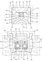
続いて、ハウジング本体11に後方からリテーナ60が装着される。リテーナ本体61は、凹所66に電線110が進入することで、電線110との干渉が回避される(図2および図4を参照)。検知片64は、キャビティ16の後面開口の上端に斜面72が摺動可能にガイドされた後、キャビティ16内の上壁に沿って隙間80に挿入される。リテーナ60がハウジング10に装着された状態では、検知片64の検知面71が箱部41の上部後端、詳細には押え壁48を含む架壁47から両側壁45、46の上部にわたる部分の後端となる接触領域58に対向して配置される(図3および図4を参照)。
Subsequently, the
仮に、端子金具40がキャビティ16内に正規深さで挿入されていないと、箱部41の接触領域58に検知片64が強く当たり、端子金具40が半挿入状態で留め置かれていることを検知することができる。また、その状態からリテーナ60を強く押し込んでハウジング本体11に装着させることにより、端子金具40を検知片64で押圧して正規の挿入位置に至らすことができる。
If the terminal fitting 40 is not inserted into the
端子金具40がキャビティ16内に正規挿入された状態では、既述のとおり、検知片64の検知面71が箱部41の接触領域58に対向して配置されるため、端子金具40がキャビティ16内に二次的に抜け止めされる。仮に、電線110が後方へ引っ張られても、箱部41の接触領域58が検知片64の検知面71に当たることで、端子金具40のそれ以上の後退が規制され、端子金具40がキャビティ16内に挿入された状態が維持される。
In the state where the terminal fitting 40 is normally inserted into the
続いて、両張出部62を指で摘んだ状態で、ハウジング10が相手ハウジング90のフード部91内に嵌合される。ハウジング10がフード部91内に嵌合されると、ロックアーム12のロック部13がロック孔92に嵌り込み、両ハウジング10、90が抜け止め状態に保持される(図4を参照)。このとき、ロックアーム12は、フード部91内に配置され、後端部が保護壁14で取り囲まれていて後方にリテーナ本体61が位置していることから、外部の異物と干渉しにくくなる。その結果、異物との干渉によってロックアーム12とロック孔92とのロック状態が不用意に解除されるのが防止される。
Subsequently, the
一方、両ハウジング10、90を離脱させる際には、リテーナ本体61の孔部65に後方から治具を差し込み、治具の先端部をロックアーム12の後端部に当てて、ロックアーム12の後端部を押し下げる。すると、ロック部13がロック孔92から抜け出て、ロックアーム12とロック孔92とのロック状態が解除され、両ハウジング10、90を互いに引き離すことが可能となる。
On the other hand, when the
両ハウジング10、90が正規嵌合されると、相手端子金具30のタブ31がタブ挿通孔18を通して箱部41内に進入する。タブ31は、弾性接触片49を撓ませた状態で、接点部51と両ビード部52との間に挟まれる。こうしてタブ31が接点部51に接触することで、両端子金具30、40が正規状態で電気的に接続される。
When both
本実施例1の場合、コネクタが小型であるため、タブ31の後端部(先端部)が誤差または寸法公差の範囲で箱部41の後端から後方へ突き出ることがある。しかし、図4に示すように、タブ31の後端部は、箱部41の後端から後方へ突き出た状態で、凹部73内に進入し、検知片64との干渉を回避することができる。具体的には、検知片64の凹部73がタブ31の進行方向で対向する位置に配置されているため、タブ31の上部が凹部73の幅方向中央部に入り込み、タブ31の上面が検知本体67の下面に平行に近接して配置され、タブ31と検知片64とが接触しない状態に保たれる。
In the case of the first embodiment, since the connector is small, the rear end portion (tip portion) of the
したがって、本実施例1によれば、箱部41から突き出たタブ31が凹部73内に進入して検知片64との干渉を回避することができるため、検知片64の検知面71が箱部41の接触領域58に当たることが可能な状態を良好に維持することができ、検知片64による抜け止め機能および検知機能を適正に発揮させることができる。
Therefore, according to the first embodiment, the
特に、検知片64が凹部73を区画する門型の検知面71を有し、検知面71が端子金具40の箱部41の後端における接触領域58に当たることが可能とされ、接触領域58が架壁47のみならず押え壁48および両側壁45、46の上部に跨る広い範囲に形成されているため、端子金具40のキャビティ16からの抜け出しを規制する信頼性をより高めることができる。
In particular, the
また、箱部41がバレル部42、43よりも高背とされ、キャビティ16内の上部後方には箱部41とバレル部42、43との高低差に起因する隙間80が形成されるため、リテーナ60の装着過程で、検知片64が隙間80に挿入されてバレル部42、43と接触するのを防止することができ、リテーナ60のハウジング10への装着作業を円滑に行うことができる。
Further, the
<他の実施例>
以下、他の実施例を簡単に説明する。
(1)ハウジング本体の上面または側面などに、キャビティに連通するリテーナ装着孔が設けられ、リテーナがハウジングに対して前後方向と交差する方向からリテーナ装着孔内に挿入されて、検知片が端子金具の箱部の後端に当たることが可能となる構成であってもよい。
(2)タブは、誤差や寸法公差ではなく、そもそもの設計上、先端部が箱部の後端から後方へ突き出るものであってもよい。
(3)雄端子金具は、回路基板に接続されず、電線の端末部に接続されるバレル構造を有し、前方にタブが突出する形態であってもよい。この場合、雄ハウジングは、回路基板の上面に設置されず、固定部材が装着されない構造をとり得る。
<Other Examples>
Hereinafter, other embodiments will be briefly described.
(1) A retainer mounting hole communicating with the cavity is provided on the upper surface or the side surface of the housing body, the retainer is inserted into the retainer mounting hole from the direction intersecting the front-rear direction with respect to the housing, and the detection piece is a terminal fitting. It may be configured so that it can hit the rear end of the box portion of the box.
(2) The tab may not be an error or a dimensional tolerance, but may have a tip portion protruding rearward from the rear end of the box portion due to the design in the first place.
(3) The male terminal fitting may have a barrel structure that is not connected to the circuit board but is connected to the terminal portion of the electric wire, and the tab may protrude forward. In this case, the male housing may have a structure in which the male housing is not installed on the upper surface of the circuit board and the fixing member is not mounted.
10…ハウジング
16…キャビティ
30…相手端子金具
31…タブ
40…端子金具
41…箱部
42…ワイヤバレル部(バレル部)
43…インシュレーションバレル部(バレル部)
45…一方の側壁
46…他方の側壁
47…架壁
58…接触領域
60…リテーナ
64…検知片
71…検知面
73…凹部
90…相手ハウジング
110…電線
10 ...
43 ... Insulation barrel part (barrel part)
45 ... One
Claims (3)
前記キャビティに後方から挿入され、前後面が開口する筒状の箱部を有し、前記箱部内に前方から相手端子金具のタブが挿入される端子金具と、
前記ハウジングに装着され、前記箱部の後端に当たることが可能な検知片を有するリテーナと、を備え、
前記検知片には、前記箱部内を貫通した前記タブとの干渉を回避する凹部が設けられているコネクタ。 A housing with a cavity and
A terminal fitting that has a cylindrical box portion that is inserted into the cavity from the rear and has an open front and rear surface, and a tab of the mating terminal fitting is inserted from the front into the box portion.
A retainer mounted on the housing and having a detection piece capable of hitting the rear end of the box portion.
The detection piece is a connector provided with a recess for avoiding interference with the tab penetrating the inside of the box portion.
前記検知片は、前記凹部を区画する門型部分に検知面を有し、前記検知面が前記架壁から前記両側壁にわたる部分の後端に当たることが可能となっている請求項1に記載のコネクタ。 The box portion has a pair of side walls facing each other in the width direction and a overhead wall connecting the both side walls.
The first aspect of the present invention, wherein the detection piece has a detection surface in a gate-shaped portion for partitioning the recess, and the detection surface can hit the rear end of a portion extending from the overhead wall to both side walls. connector.
前記端子金具は、前記箱部の後方に、電線の端末部に接続されるバレル部を有し、
前記バレル部は、前記箱部の後端における前記検知片との接触領域よりも低い位置に配置されている請求項1または請求項2に記載のコネクタ。 The retainer is mounted rearward on the housing and
The terminal fitting has a barrel portion connected to the terminal portion of the electric wire behind the box portion.
The connector according to claim 1 or 2, wherein the barrel portion is arranged at a position lower than a contact region with the detection piece at the rear end of the box portion.
Priority Applications (4)
| Application Number | Priority Date | Filing Date | Title |
|---|---|---|---|
| JP2018235996A JP7001965B2 (en) | 2018-12-18 | 2018-12-18 | connector |
| CN201980083282.7A CN113228425B (en) | 2018-12-18 | 2019-11-28 | Connector with a plurality of connectors |
| PCT/JP2019/046486 WO2020129563A1 (en) | 2018-12-18 | 2019-11-28 | Connector |
| US17/415,148 US11626683B2 (en) | 2018-12-18 | 2019-11-28 | Connector with retainer |
Applications Claiming Priority (1)
| Application Number | Priority Date | Filing Date | Title |
|---|---|---|---|
| JP2018235996A JP7001965B2 (en) | 2018-12-18 | 2018-12-18 | connector |
Publications (2)
| Publication Number | Publication Date |
|---|---|
| JP2020098705A JP2020098705A (en) | 2020-06-25 |
| JP7001965B2 true JP7001965B2 (en) | 2022-01-20 |
Family
ID=71101675
Family Applications (1)
| Application Number | Title | Priority Date | Filing Date |
|---|---|---|---|
| JP2018235996A Active JP7001965B2 (en) | 2018-12-18 | 2018-12-18 | connector |
Country Status (4)
| Country | Link |
|---|---|
| US (1) | US11626683B2 (en) |
| JP (1) | JP7001965B2 (en) |
| CN (1) | CN113228425B (en) |
| WO (1) | WO2020129563A1 (en) |
Citations (1)
| Publication number | Priority date | Publication date | Assignee | Title |
|---|---|---|---|---|
| JP2010267523A (en) | 2009-05-15 | 2010-11-25 | Sumitomo Wiring Syst Ltd | Connector |
Family Cites Families (28)
| Publication number | Priority date | Publication date | Assignee | Title |
|---|---|---|---|---|
| JPH0192773U (en) * | 1987-12-14 | 1989-06-19 | ||
| JPH0371576U (en) * | 1989-11-17 | 1991-07-19 | ||
| JP3358357B2 (en) * | 1994-12-08 | 2002-12-16 | 住友電装株式会社 | Board connector |
| JP3274348B2 (en) * | 1996-03-15 | 2002-04-15 | 矢崎総業株式会社 | Connector mating detection device |
| JPH10321281A (en) * | 1997-05-16 | 1998-12-04 | Sumitomo Wiring Syst Ltd | Connector |
| JP3405440B2 (en) * | 1997-08-22 | 2003-05-12 | 住友電装株式会社 | Connector with retainer |
| US6435894B2 (en) * | 1998-07-15 | 2002-08-20 | Tyco Electronics Logistics Ag | Connector for airbag gas generator |
| JP3508016B2 (en) * | 1999-12-24 | 2004-03-22 | 住友電装株式会社 | connector |
| JP2002015807A (en) * | 2000-06-29 | 2002-01-18 | Sumitomo Wiring Syst Ltd | Connector |
| US6893277B2 (en) * | 2003-02-26 | 2005-05-17 | Tyco Electronics Corporation | Squib connector assembly with CPA |
| JP2004327321A (en) * | 2003-04-25 | 2004-11-18 | Jst Mfg Co Ltd | Connector |
| DE102004023446B3 (en) * | 2004-05-12 | 2005-12-29 | Fci | Connector and method of its pre-assembly |
| DE102005001515B4 (en) * | 2005-01-13 | 2008-01-31 | Amphenol-Tuchel Electronics Gmbh | Electrical connector |
| FR2931307B1 (en) * | 2008-05-19 | 2010-05-07 | Ncs Pyrotechnie & Tech | ELECTRICAL CONNECTION PART FORMED OF A TWO-BRANCH HOUSING WITH 90 ° ORIENTS |
| US8021200B2 (en) * | 2008-08-04 | 2011-09-20 | Tyco Electronics Corporation | Socket contact |
| DE102009052772B4 (en) * | 2008-12-01 | 2014-02-13 | Sumitomo Wiring Systems, Ltd. | A connector |
| JP5375687B2 (en) * | 2010-03-15 | 2013-12-25 | 株式会社オートネットワーク技術研究所 | Terminal fittings and wires with terminal fittings |
| TWM475057U (en) * | 2013-10-11 | 2014-03-21 | Singatron Entpr Co Ltd | USB socket connector with detection utility |
| JP6347228B2 (en) * | 2015-05-11 | 2018-06-27 | 住友電装株式会社 | connector |
| JP6344321B2 (en) * | 2015-06-25 | 2018-06-20 | 住友電装株式会社 | connector |
| JP6418101B2 (en) * | 2015-08-07 | 2018-11-07 | 株式会社オートネットワーク技術研究所 | Electrical connection device having fitting detection function |
| JP6422905B2 (en) * | 2016-03-09 | 2018-11-14 | 矢崎総業株式会社 | connector |
| US9660379B1 (en) * | 2016-05-18 | 2017-05-23 | Ford Global Technologies, Llc | Vehicle electrical connector assembly and connection method |
| CN206180254U (en) * | 2016-11-24 | 2017-05-17 | 骑记(厦门)科技有限公司 | Electric connector |
| JP2018190670A (en) * | 2017-05-11 | 2018-11-29 | 住友電装株式会社 | Connector with retainer |
| JP6754389B2 (en) * | 2018-04-04 | 2020-09-09 | 矢崎総業株式会社 | connector |
| JP2020080269A (en) * | 2018-11-14 | 2020-05-28 | 住友電装株式会社 | connector |
| TWI754961B (en) * | 2019-12-18 | 2022-02-11 | 大陸商東莞訊滔電子有限公司 | Connector |
-
2018
- 2018-12-18 JP JP2018235996A patent/JP7001965B2/en active Active
-
2019
- 2019-11-28 CN CN201980083282.7A patent/CN113228425B/en active Active
- 2019-11-28 WO PCT/JP2019/046486 patent/WO2020129563A1/en active Application Filing
- 2019-11-28 US US17/415,148 patent/US11626683B2/en active Active
Patent Citations (1)
| Publication number | Priority date | Publication date | Assignee | Title |
|---|---|---|---|---|
| JP2010267523A (en) | 2009-05-15 | 2010-11-25 | Sumitomo Wiring Syst Ltd | Connector |
Also Published As
| Publication number | Publication date |
|---|---|
| US20220059963A1 (en) | 2022-02-24 |
| CN113228425A (en) | 2021-08-06 |
| WO2020129563A1 (en) | 2020-06-25 |
| US11626683B2 (en) | 2023-04-11 |
| CN113228425B (en) | 2023-11-28 |
| JP2020098705A (en) | 2020-06-25 |
Similar Documents
| Publication | Publication Date | Title |
|---|---|---|
| EP1936749B1 (en) | A terminal fitting, a connector and a forming method | |
| KR101886959B1 (en) | Connector | |
| US7252549B2 (en) | Connector, receptacle for connector and plug for connector | |
| JP5059571B2 (en) | Female terminal bracket for PCB | |
| US8206170B2 (en) | Male and female connectors and electrical connector including the same | |
| US7575464B2 (en) | Connector with channel-shaped clearance between lock arm and projection to prevent entry of wires | |
| JP4985206B2 (en) | Connector and short terminal | |
| KR101226418B1 (en) | Terminal fitting | |
| JP2009206059A (en) | Electric connector | |
| JP5809203B2 (en) | Flat conductor electrical connector | |
| US7101233B2 (en) | Female terminal fitting | |
| JP2017111851A (en) | Terminal fitting | |
| JP2017091761A (en) | connector | |
| US8333606B2 (en) | Electrical connector having a terminal with a connecting section and a held section on two opposite sides of a contact section | |
| JP6352676B2 (en) | connector | |
| US20200212617A1 (en) | Connector | |
| US10770837B2 (en) | Connector having a slider holder | |
| KR102128123B1 (en) | Plug connector | |
| JP7001965B2 (en) | connector | |
| US11276959B2 (en) | Electrical connection device | |
| US20160372854A1 (en) | Plug connector assembly for establishing an electrical plug connection | |
| US20190267740A1 (en) | Connector | |
| US7607945B2 (en) | Connector | |
| US7001224B2 (en) | Connector with retainer for locking terminal fitings | |
| JP6123670B2 (en) | Built-in capacitor type connector |
Legal Events
| Date | Code | Title | Description |
|---|---|---|---|
| A621 | Written request for application examination |
Free format text: JAPANESE INTERMEDIATE CODE: A621 Effective date: 20210330 |
|
| TRDD | Decision of grant or rejection written | ||
| A01 | Written decision to grant a patent or to grant a registration (utility model) |
Free format text: JAPANESE INTERMEDIATE CODE: A01 Effective date: 20211125 |
|
| A61 | First payment of annual fees (during grant procedure) |
Free format text: JAPANESE INTERMEDIATE CODE: A61 Effective date: 20211208 |
|
| R150 | Certificate of patent or registration of utility model |
Ref document number: 7001965 Country of ref document: JP Free format text: JAPANESE INTERMEDIATE CODE: R150 |