JP6999670B2 - Applicator instrument with range of motion shaft to supply surgical fasteners - Google Patents
Applicator instrument with range of motion shaft to supply surgical fasteners Download PDFInfo
- Publication number
- JP6999670B2 JP6999670B2 JP2019530395A JP2019530395A JP6999670B2 JP 6999670 B2 JP6999670 B2 JP 6999670B2 JP 2019530395 A JP2019530395 A JP 2019530395A JP 2019530395 A JP2019530395 A JP 2019530395A JP 6999670 B2 JP6999670 B2 JP 6999670B2
- Authority
- JP
- Japan
- Prior art keywords
- distal
- proximal
- motion
- shaft portion
- housing
- Prior art date
- Legal status (The legal status is an assumption and is not a legal conclusion. Google has not performed a legal analysis and makes no representation as to the accuracy of the status listed.)
- Active
Links
Images


Classifications
-
- A—HUMAN NECESSITIES
- A61—MEDICAL OR VETERINARY SCIENCE; HYGIENE
- A61B—DIAGNOSIS; SURGERY; IDENTIFICATION
- A61B17/00—Surgical instruments, devices or methods, e.g. tourniquets
- A61B17/068—Surgical staplers, e.g. containing multiple staples or clamps
-
- A—HUMAN NECESSITIES
- A61—MEDICAL OR VETERINARY SCIENCE; HYGIENE
- A61B—DIAGNOSIS; SURGERY; IDENTIFICATION
- A61B17/00—Surgical instruments, devices or methods, e.g. tourniquets
- A61B17/00234—Surgical instruments, devices or methods, e.g. tourniquets for minimally invasive surgery
-
- A—HUMAN NECESSITIES
- A61—MEDICAL OR VETERINARY SCIENCE; HYGIENE
- A61B—DIAGNOSIS; SURGERY; IDENTIFICATION
- A61B17/00—Surgical instruments, devices or methods, e.g. tourniquets
- A61B17/064—Surgical staples, i.e. penetrating the tissue
-
- A—HUMAN NECESSITIES
- A61—MEDICAL OR VETERINARY SCIENCE; HYGIENE
- A61B—DIAGNOSIS; SURGERY; IDENTIFICATION
- A61B17/00—Surgical instruments, devices or methods, e.g. tourniquets
- A61B17/068—Surgical staplers, e.g. containing multiple staples or clamps
- A61B17/0682—Surgical staplers, e.g. containing multiple staples or clamps for applying U-shaped staples or clamps, e.g. without a forming anvil
-
- A—HUMAN NECESSITIES
- A61—MEDICAL OR VETERINARY SCIENCE; HYGIENE
- A61F—FILTERS IMPLANTABLE INTO BLOOD VESSELS; PROSTHESES; DEVICES PROVIDING PATENCY TO, OR PREVENTING COLLAPSING OF, TUBULAR STRUCTURES OF THE BODY, e.g. STENTS; ORTHOPAEDIC, NURSING OR CONTRACEPTIVE DEVICES; FOMENTATION; TREATMENT OR PROTECTION OF EYES OR EARS; BANDAGES, DRESSINGS OR ABSORBENT PADS; FIRST-AID KITS
- A61F2/00—Filters implantable into blood vessels; Prostheses, i.e. artificial substitutes or replacements for parts of the body; Appliances for connecting them with the body; Devices providing patency to, or preventing collapsing of, tubular structures of the body, e.g. stents
- A61F2/02—Prostheses implantable into the body
-
- A—HUMAN NECESSITIES
- A61—MEDICAL OR VETERINARY SCIENCE; HYGIENE
- A61B—DIAGNOSIS; SURGERY; IDENTIFICATION
- A61B17/00—Surgical instruments, devices or methods, e.g. tourniquets
- A61B17/068—Surgical staplers, e.g. containing multiple staples or clamps
- A61B17/072—Surgical staplers, e.g. containing multiple staples or clamps for applying a row of staples in a single action, e.g. the staples being applied simultaneously
- A61B17/07207—Surgical staplers, e.g. containing multiple staples or clamps for applying a row of staples in a single action, e.g. the staples being applied simultaneously the staples being applied sequentially
-
- A—HUMAN NECESSITIES
- A61—MEDICAL OR VETERINARY SCIENCE; HYGIENE
- A61B—DIAGNOSIS; SURGERY; IDENTIFICATION
- A61B17/00—Surgical instruments, devices or methods, e.g. tourniquets
- A61B17/00234—Surgical instruments, devices or methods, e.g. tourniquets for minimally invasive surgery
- A61B2017/00292—Surgical instruments, devices or methods, e.g. tourniquets for minimally invasive surgery mounted on or guided by flexible, e.g. catheter-like, means
- A61B2017/003—Steerable
- A61B2017/00305—Constructional details of the flexible means
- A61B2017/00314—Separate linked members
-
- A—HUMAN NECESSITIES
- A61—MEDICAL OR VETERINARY SCIENCE; HYGIENE
- A61B—DIAGNOSIS; SURGERY; IDENTIFICATION
- A61B17/00—Surgical instruments, devices or methods, e.g. tourniquets
- A61B17/00234—Surgical instruments, devices or methods, e.g. tourniquets for minimally invasive surgery
- A61B2017/00292—Surgical instruments, devices or methods, e.g. tourniquets for minimally invasive surgery mounted on or guided by flexible, e.g. catheter-like, means
- A61B2017/003—Steerable
- A61B2017/00318—Steering mechanisms
- A61B2017/00323—Cables or rods
- A61B2017/00327—Cables or rods with actuating members moving in opposite directions
-
- A—HUMAN NECESSITIES
- A61—MEDICAL OR VETERINARY SCIENCE; HYGIENE
- A61B—DIAGNOSIS; SURGERY; IDENTIFICATION
- A61B17/00—Surgical instruments, devices or methods, e.g. tourniquets
- A61B2017/00367—Details of actuation of instruments, e.g. relations between pushing buttons, or the like, and activation of the tool, working tip, or the like
- A61B2017/00407—Ratchet means
-
- A—HUMAN NECESSITIES
- A61—MEDICAL OR VETERINARY SCIENCE; HYGIENE
- A61B—DIAGNOSIS; SURGERY; IDENTIFICATION
- A61B17/00—Surgical instruments, devices or methods, e.g. tourniquets
- A61B2017/00526—Methods of manufacturing
- A61B2017/0053—Loading magazines or sutures into applying tools
-
- A—HUMAN NECESSITIES
- A61—MEDICAL OR VETERINARY SCIENCE; HYGIENE
- A61B—DIAGNOSIS; SURGERY; IDENTIFICATION
- A61B17/00—Surgical instruments, devices or methods, e.g. tourniquets
- A61B17/068—Surgical staplers, e.g. containing multiple staples or clamps
- A61B2017/0688—Packages or dispensers for surgical staplers
-
- A—HUMAN NECESSITIES
- A61—MEDICAL OR VETERINARY SCIENCE; HYGIENE
- A61B—DIAGNOSIS; SURGERY; IDENTIFICATION
- A61B17/00—Surgical instruments, devices or methods, e.g. tourniquets
- A61B17/28—Surgical forceps
- A61B17/29—Forceps for use in minimally invasive surgery
- A61B17/2909—Handles
- A61B2017/291—Handles the position of the handle being adjustable with respect to the shaft
-
- A—HUMAN NECESSITIES
- A61—MEDICAL OR VETERINARY SCIENCE; HYGIENE
- A61B—DIAGNOSIS; SURGERY; IDENTIFICATION
- A61B17/00—Surgical instruments, devices or methods, e.g. tourniquets
- A61B17/28—Surgical forceps
- A61B17/29—Forceps for use in minimally invasive surgery
- A61B17/2909—Handles
- A61B2017/2912—Handles transmission of forces to actuating rod or piston
- A61B2017/2923—Toothed members, e.g. rack and pinion
-
- A—HUMAN NECESSITIES
- A61—MEDICAL OR VETERINARY SCIENCE; HYGIENE
- A61B—DIAGNOSIS; SURGERY; IDENTIFICATION
- A61B17/00—Surgical instruments, devices or methods, e.g. tourniquets
- A61B17/28—Surgical forceps
- A61B17/29—Forceps for use in minimally invasive surgery
- A61B17/2909—Handles
- A61B2017/2925—Pistol grips
-
- A—HUMAN NECESSITIES
- A61—MEDICAL OR VETERINARY SCIENCE; HYGIENE
- A61B—DIAGNOSIS; SURGERY; IDENTIFICATION
- A61B17/00—Surgical instruments, devices or methods, e.g. tourniquets
- A61B17/28—Surgical forceps
- A61B17/29—Forceps for use in minimally invasive surgery
- A61B2017/2926—Details of heads or jaws
- A61B2017/2927—Details of heads or jaws the angular position of the head being adjustable with respect to the shaft
-
- A—HUMAN NECESSITIES
- A61—MEDICAL OR VETERINARY SCIENCE; HYGIENE
- A61B—DIAGNOSIS; SURGERY; IDENTIFICATION
- A61B34/00—Computer-aided surgery; Manipulators or robots specially adapted for use in surgery
- A61B34/30—Surgical robots
- A61B2034/305—Details of wrist mechanisms at distal ends of robotic arms
- A61B2034/306—Wrists with multiple vertebrae
-
- A—HUMAN NECESSITIES
- A61—MEDICAL OR VETERINARY SCIENCE; HYGIENE
- A61B—DIAGNOSIS; SURGERY; IDENTIFICATION
- A61B90/00—Instruments, implements or accessories specially adapted for surgery or diagnosis and not covered by any of the groups A61B1/00 - A61B50/00, e.g. for luxation treatment or for protecting wound edges
- A61B90/08—Accessories or related features not otherwise provided for
- A61B2090/0807—Indication means
- A61B2090/0808—Indication means for indicating correct assembly of components, e.g. of the surgical apparatus
-
- A—HUMAN NECESSITIES
- A61—MEDICAL OR VETERINARY SCIENCE; HYGIENE
- A61B—DIAGNOSIS; SURGERY; IDENTIFICATION
- A61B34/00—Computer-aided surgery; Manipulators or robots specially adapted for use in surgery
- A61B34/30—Surgical robots
- A61B34/37—Master-slave robots
-
- A—HUMAN NECESSITIES
- A61—MEDICAL OR VETERINARY SCIENCE; HYGIENE
- A61B—DIAGNOSIS; SURGERY; IDENTIFICATION
- A61B90/00—Instruments, implements or accessories specially adapted for surgery or diagnosis and not covered by any of the groups A61B1/00 - A61B50/00, e.g. for luxation treatment or for protecting wound edges
- A61B90/90—Identification means for patients or instruments, e.g. tags
- A61B90/92—Identification means for patients or instruments, e.g. tags coded with colour
Description
(関連出願の相互参照)
本特許出願は、2016年12月7日に出願された米国特許仮出願第62/431,355号の利益を主張し、「SURGICAL FASTENERS FOR MESH AND TISSUE FIXATION」(代理人整理番号ETH5878USNP)と題する、2016年12月7日に出願された米国特許出願第15/372,241号に関連し、それらの開示は、参照により本明細書に組み込まれる。
(Mutual reference of related applications)
This patent application claims the benefit of U.S. Patent Application No. 62 / 431,355 filed December 7, 2016 and is entitled "SURGICAL FASTENEERS FOR MESH AND TISSUE FIXATION" (agent reference number ETH5878USNP). , US Patent Application No. 15 / 372,241 filed December 7, 2016, the disclosures of which are incorporated herein by reference.
(発明の分野)
本特許出願は、概して、医療装置に関し、より具体的には、プロテーゼ装置を組織に固定するための外科用締結具を供給する医療装置に関する。
(Field of invention)
The patent application generally relates to medical devices, and more specifically to medical devices that provide surgical fasteners for fixing the prosthesis device to tissue.
ヘルニアは、患者の腹筋壁又は鼠径部内の弱い場所又は欠損部を貫通して腸(bowel or intestine)の小さいループが突出する症状である。この状態は一般的にヒト、特に男性に生じる。この種のヘルニアは、先天性欠陥から生じる場合があり、患者は生まれつきヘルニアの素因を有しているか、以前に腹部の手術を受けているか、又は酷使する若しくは重いものを持ち上げることによって生じ得る。重いものを持ち上げることは腹壁に多大な圧力を生じさせることは既知であり得、腹筋の弱い部分で破裂又は破断を生じさせ、欠損部又は開口を生じさせる場合がある。いずれの場合においても、患者はその欠損部を貫通して突出する見た目の悪い腸組織の出っ張りを有する状態となり、これが痛み、持ち上げる力の低下を生じさせる場合があり、場合によっては腸の圧迫、又は、突出組織への血流が遮断された場合は他の合併症を生じさせる可能性がある。 A hernia is a condition in which a small loop of the bowel or intestine protrudes through a weak spot or defect in the patient's abdominal muscle wall or groin. This condition generally occurs in humans, especially men. This type of hernia can result from a congenital defect, which can result from the patient having a natural predisposition to the hernia, having previously undergone abdominal surgery, or overworking or lifting a heavy object. It can be known that lifting heavy objects creates a great deal of pressure on the abdominal wall, which can cause ruptures or breaks in weak areas of the abdominal muscles, resulting in defects or openings. In either case, the patient will have a bulge of unsightly intestinal tissue that protrudes through the defect, which can cause pain, diminished lifting force, and in some cases intestinal compression, Alternatively, if blood flow to the protruding tissue is blocked, other complications may occur.
上述した問題に対する一般的な解決法は外科手術であり得る。外科的手術中、開いた切開部を通じて、又はトロカールなどのアクセスポートを通じて内視鏡的に、欠損部にアクセスし、欠損部を注意深く検査する。いずれの場合でも、血管及び神経の網状組織が典型的な欠損領域に存在するために注意深い検査が必要とされ、外科医は高度な技術及び注意をもってヘルニア治療を行う必要がある。この領域には、胃血管、外腸骨血管、及び下腹壁血管、並びに鼠径床を通じて延びる輸精管などの生殖管などの血管構造が見出され得る。 A common solution to the problems mentioned above can be surgery. During surgery, the defect is accessed endoscopically through an open incision or through an access port such as a trocar and the defect is carefully examined. In either case, careful examination is required due to the presence of vascular and nerve reticular tissue in the typical defect area, and the surgeon needs to treat the hernia with a high degree of skill and care. Vascular structures such as gastric vessels, external iliac vessels, and inferior epigastric vessels, as well as reproductive ducts such as the vas deferens extending through the inguinal bed, can be found in this region.
一旦、外科医が患者の生体構造に精通すると、外科医は、欠損部を通して内臓を患者の腹部内に慎重に定置し戻す。欠損部の修復は、縫合糸又は締結具を用いた欠損部の閉鎖を伴う場合があるが、一般的には、欠損部上へのメッシュパッチなどの外科用プロテーゼの配置、及び従来型の縫合糸又は外科用締結具を用いた、腹壁又は鼠径床へのメッシュパッチの取り付けを伴う。メッシュパッチはバリアとして機能し、欠損部を通した腸の圧出を防ぐ。鼠径床にメッシュパッチを縫合することは開放式手術に非常に適している場合があるが、内視鏡手術では、はるかに困難で時間がかかる場合がある。内視鏡手術が適用される場合、外科用締結具を適用する内視鏡外科用器具が使用され得る。しかしながら、鼠径床の組織は、クーパー靭帯などの構造を貫通するために針又は締結具が使用される場合に、特殊な困難を外科医に提示し得る。 Once the surgeon is familiar with the patient's anatomy, the surgeon carefully places the internal organs back into the patient's abdomen through the defect. Repair of the defect may involve closure of the defect with sutures or fasteners, but generally, placement of a surgical prosthesis such as a mesh patch over the defect, and conventional suturing. Accompanied by the attachment of a mesh patch to the abdominal wall or inguinal bed using sutures or surgical fasteners. The mesh patch acts as a barrier, preventing intestinal extrusion through the defect. Suturing a mesh patch to the inguinal bed can be very suitable for open surgery, but endoscopic surgery can be much more difficult and time consuming. If endoscopic surgery is applied, endoscopic surgical instruments to which surgical fasteners are applied may be used. However, the tissue of the inguinal bed may present special difficulties to the surgeon when needles or fasteners are used to penetrate structures such as the Cooper's ligament.
現在、メッシュパッチを腹壁又は鼠径床に取り付けるために、内視鏡又は開放式手術において外科医が使用するために利用できる、様々な外科用器具及び締結具が存在する。使用される最も古いタイプの内視鏡外科用器具の1つは、外科用ステープラーである。複数の又は積み重ねた、これらの形成されていないステープルは一般的に、連続的な様式でステープルカートリッジ内に収容されている場合があり、かつ、ばね機構によって器具内で順次前進させられるか又は送達され得る。二次弁機構又は送達機構が、積み重ね体から最遠位ステープルを分離して、ばね荷重された積み重ね体の残りを保持するために利用され得、かつ最遠位ステープルをステープル形成機構に送達するために使用され得る。この種類の送達機構は、米国特許第5,470,010号(Rothfussら)、及び米国特許第5,582,616号(同じくRothfussら)に見出される。 Currently, there are various surgical instruments and fasteners available for use by surgeons in endoscopy or open surgery to attach the mesh patch to the abdominal wall or inguinal bed. One of the oldest types of endoscopic surgical instruments used is the surgical stapler. Multiple or stacked, these non-formed staples may generally be housed in staple cartridges in a continuous fashion and are sequentially advanced or delivered within the instrument by a spring mechanism. Can be done. A secondary valve mechanism or delivery mechanism can be utilized to separate the distal staples from the stack to retain the rest of the spring loaded stack and deliver the distal staples to the staple forming mechanism. Can be used for. This type of delivery mechanism is found in US Pat. No. 5,470,010 (Rothfuss et al.) And US Pat. No. 5,582,616 (also Rothfuss et al.).
別のヘルニアメッシュ取り付け器具は、ばねの小部分に似た螺旋状ワイヤ締結具を用いる。多数の螺旋状ワイヤ締結具は、5mmシャフト内に連続的に保存されてもよく、組織内へと螺旋状に又は回転されて進められもよい。荷重ばねが、複数の螺旋状締結具をシャフト内の遠位方向に付勢又は送達するために用いられ得る。突出部はシャフト内に延伸して、荷重ばねによる締結具の積み重ね体の排出を防ぎ得、また回転式締結具の通過を可能にし得る。これらの種類の器具及び締結具は、米国特許第5,582,616号(Bolducら)、米国特許第5,810,882号(Bolducら)、及び米国特許第5,830,221号(Steinら)に見出される。 Another hernia mesh attachment uses a spiral wire fastener that resembles a small portion of a spring. A large number of spiral wire fasteners may be continuously stored within the 5 mm shaft and may be spirally or rotated into the tissue. Load springs can be used to urge or deliver multiple spiral fasteners distally within the shaft. The protrusions can be extended into the shaft to prevent the load springs from ejecting the fastener stack and also allow the rotary fasteners to pass through. These types of appliances and fasteners include US Pat. No. 5,582,616 (Bolduc et al.), US Pat. No. 5,810,882 (Bolduc et al.), And US Pat. No. 5,830,221 (Stain). Et al.).
一方で、上記の外科用器具はヘルニア締結用途に使用されてもよく、これらは外科用器具を通じて複数の締結具を送達するためにばね機構を使用する。ばね機構は、通常、長く柔らかいコイルばねを使用して、外科用器具のシャフト内のガイド又はトラックを介して締結具の積み重ね体を押す。これらの種類の送達機構は、一般的に単純かつ確実であり得るが、1つの締結具を積み重ね体から分離し送達するために、追加的な二次弁機構又は突出部を必要とし得る。 On the other hand, the surgical instruments described above may be used for hernia fastening applications, which use a spring mechanism to deliver a plurality of fasteners through the surgical instrument. The spring mechanism typically uses a long, soft coil spring to push the fastener stack through a guide or track within the shaft of the surgical instrument. These types of delivery mechanisms may generally be simple and reliable, but may require additional secondary valve mechanisms or protrusions to separate and deliver one fastener from the stack.
ヘルニアメッシュ取り付けのために、他の外科用締結具が使用され得るが、そうした締結具は、少量の締結具を保持する、再装填可能な単発器具又は回転式マガジンのいずれかを利用する。これらの種類の外科用締結器具は、米国特許第5,203,864号及び同第5,290,297号(いずれもEdward Phillips)に見出され得る。これらの器具は外科のコミュニティでは受け入れられておらず、その理由は恐らくは、これらの単発の能力及び回転式マガジンの大きな寸法により、これらがこのような器具を開放式手術に限定するためである。 Other surgical fasteners may be used for hernia mesh attachment, but such fasteners utilize either a reloadable single-shot instrument or a rotary magazine that holds a small amount of fasteners. These types of surgical fasteners can be found in US Pat. Nos. 5,203,864 and 5,290,297 (both Edward Phillips). These instruments have not been accepted by the surgical community, probably because of their single-shot capabilities and the large dimensions of the rotary magazine, which limit such instruments to open surgery.
上記の全ての外科用器具はヘルニア締結用途に使用され得るが、これらは外科用器具を通じて複数の締結具を送達するためのばね機構、又は送達機構の代わりに回転式マガジンのいずれかを使用する。外科用クリップなどの、他の種類の外科用締結具も利用可能であり得、これらはクリップを遠位に送達するために、ばねの使用を必要としない送達機構を利用し得る。往復式送達機構は、Fogelbergらの米国特許第5,601,573号、同第5,833,700号、及び同第5,921,997号に記載されている。Fogelbergらの参照文献は、往復式フィードバーを利用して一連のクリップ積み重ね体を送達する送達機構を備えたクリップ適用器具を教示している。フィーダーシューは遠位方向に移動するフィードバーと動作可能に係合してかつ共に移動し、また近位方向に移動するフィードバーと摺動可能に係合し得る。そのため、フィーダーシューは、遠位方向に移動するフィードバーと共にクリップの積み重ね体を遠位方向に割送り又は押すことができ、近位方向に移動するフィードバーに対しては静止状態を維持する。積み重ね体から最遠位クリップを分離し、最遠位クリップが血管に適用され得る際に積み重ね体を静的に保持するために、弁機構も必要とされ得る。Fogelbergらの参照文献は、単一の往復部材を有する往復式送達機構を教示するが、これらはヘルニアメッシュの取り付けにおけるクリップ適用器具の使用を教示せず、また移動部材による各クリップの個別の駆動又は送達を教示することもない。 All of the above surgical instruments can be used for hernia fastening applications, but they use either a spring mechanism for delivering multiple fasteners through the surgical instrument, or a rotary magazine instead of the delivery mechanism. .. Other types of surgical fasteners, such as surgical clips, may also be available, which may utilize delivery mechanisms that do not require the use of springs to deliver the clips distally. Reciprocating delivery mechanisms are described in US Pat. Nos. 5,601,573, 5,833,700, and 5,921,997 of Fogelberg et al. References by Fogelberg et al. Teach a clip application device with a delivery mechanism that utilizes a reciprocating feed bar to deliver a series of clip stacks. The feeder shoe may operably engage and move with the distally moving feed bar and slidably engage with the proximally moving feed bar. Therefore, the feeder shoe can split or push the stack of clips in the distal direction together with the feed bar moving in the distal direction, and remains stationary with respect to the feed bar moving in the proximal direction. A valve mechanism may also be required to separate the distal clip from the stack and statically hold the stack as the distal clip can be applied to the blood vessel. References by Fogelberg et al. Teach reciprocating delivery mechanisms with a single reciprocating member, but they do not teach the use of clip-applied instruments in the attachment of hernia meshes, and the individual drive of each clip by a moving member. Or it does not teach delivery.
DeCarlo Jr.の米国特許第3,740,994号は、複数のステープル又はクリップを割送りし、かつ一対の対向する板ばねアセンブリのうちの一方を往復運動させることによって複数のステープル又はクリップの発射を準備させる往復式送達機構を開示している。ステープルは、ガイドレールの平面内に延在する固定した板ばねアセンブリと共に、ガイドレール内に連続して存在する。往復運動する板ばねアセンブリは、固定された板ばねアセンブリに向けて内方に延在し得る。往復式板ばねアセンブリが遠位方向に移動すると、アセンブリの独立した板ばねの各々はステープルと係合してこれを遠位方向に移動させ得る。遠位方向に移動するステープルによって、固定した板ばねアセンブリの局所の独立した板ばねが偏向され、偏向した板ばねは、ステープルが通過した後に非偏向位置に戻り得る。移動する板ばねアセンブリが近位方向に移動すると、固定した板ばねアセンブリの板ばねはステープルを静止状態に維持し、その近位への移動を防ぐ。二次ガイドレール及び弁機構を、積み重ね体から単一のステープルを分離して形成するために提供することができ、また単一のクリップが形成されると、ステープルの積み重ね体を静止状態に維持することができる。 DeCarlo Jr. US Pat. No. 3,740,994 prepares the firing of multiple staples or clips by splitting multiple staples or clips and reciprocating one of a pair of opposing leaf spring assemblies. The reciprocating delivery mechanism is disclosed. Staples are continuously present in the guide rail, with a fixed leaf spring assembly extending in the plane of the guide rail. The reciprocating leaf spring assembly can extend inward towards the fixed leaf spring assembly. As the reciprocating leaf spring assembly moves distally, each of the independent leaf springs in the assembly may engage the staple and move it distally. The distally moving staple deflects the local independent leaf spring of the fixed leaf spring assembly, and the deflected leaf spring can return to the non-deflected position after the staple has passed. When the moving leaf spring assembly moves proximally, the leaf springs of the fixed leaf spring assembly keep the staples stationary and prevent their proximal movement. Secondary guide rails and valve mechanisms can be provided to separate and form a single staple from the stack, and once a single clip is formed, the staple stack remains stationary. can do.
加えて、類似の送達機構は、米国特許第4,478,220号(DiGiovanniら)、及び米国特許第4,471,780号(Mengesら)に開示されている。これらの関連特許の両方には、1つの固定部材及び1つの往復部材を用いて、複数のクリップを遠位方向に送達するか又は割送る往復式送達機構が教示されている。角度を付けられた可撓性指部が、ヒンジ連結によって往復部材に取り付けられ、遠位方向に移動するときにクリップと動作可能に係合し、近位方向に移動するときにクリップと摺動可能に係合し得る。クリップが遠位方向に移動して跳ね上がると、固定された部材内の角度を付けられた可撓性指部が常道を外れて偏向し、クリップが通過した後にクリップの近位への移動を阻止する。二次弁機構も更に開示される。 In addition, similar delivery mechanisms are disclosed in US Pat. No. 4,478,220 (DiGiovanni et al.) And US Pat. No. 4,471,780 (Menges et al.). Both of these related patents teach a reciprocating delivery mechanism that delivers or splits multiple clips distally using one fixation member and one reciprocating member. An angled flexible finger is attached to the reciprocating member by a hinge connection, operably engages the clip when moving distally, and slides with the clip when moving proximally. Can engage as possible. As the clip moves distally and pops up, the angled flexible fingers within the fixed member deflect out of the way and prevent the clip from moving proximally after it has passed. do. The secondary valve mechanism is also further disclosed.
開示内容が参照により本明細書に組み込まれる、本願と同一譲受人に譲渡された米国特許第7,485,124号は、複数の独立した外科用締結具を送達するための装置を教示している。一実施形態において、送達装置は、遠位端及び近位端を有する駆動機構を含む。駆動機構は、移動部材及び固定された対向部材を有し、それにより、移動部材は送達装置に対して近位方向及び遠位方向に移動可能である。移動部材は、組織を貫通するための尖った遠位端を有する。装置は、第1の部材と第2の部材との間に位置する少なくとも1つの外科用締結具を含む。少なくとも1つの外科用締結具の各々は、近位端及び遠位端を有する。装置はまた、少なくとも2つの連続位置を有するアクチュエータを有する。移動部材を遠位方向に移動させ、組織を貫通するための第1の位置、及び移動部材を近位方向に移動させ、それによって締結具の遠位端を展開するための第2の位置である。 U.S. Pat. No. 7,485,124, assigned to the same assignee as the present application, of which the disclosure is incorporated herein by reference, teaches a device for delivering multiple independent surgical fasteners. There is. In one embodiment, the delivery device comprises a drive mechanism having a distal end and a proximal end. The drive mechanism has a moving member and a fixed facing member, whereby the moving member is movable in the proximal and distal directions with respect to the delivery device. The moving member has a pointed distal end to penetrate the tissue. The device includes at least one surgical fastener located between the first member and the second member. Each of the at least one surgical fastener has a proximal end and a distal end. The device also has an actuator with at least two contiguous positions. In the first position to move the moving member distally and through the tissue, and in the second position to move the moving member proximally and thereby deploy the distal end of the fastener. be.
腹腔鏡的に使用されるメッシュを固定するためのタックは、一般的にステンレス鋼、ニチノール、又はチタンなどの金属から作製されている。金属製タックは、十分な保持強度、様々な人工メッシュの貫通、及び製造の容易さを提供するために必要であった。最近まで市販の吸収性タックは存在せず、外科医は、身体内に恒久的に残留しない固定手段を提供するには吸収性縫合糸を使用するしかなかった。しかしながら、縫合糸の使用は、腹腔鏡処置では過度に困難であるので、修復が開放式で行われる場合を除いては一般的に使用されない。異質体の蓄積が最小限である、より低い侵襲性の技術に繋がる外科的傾向により、腹腔鏡的に適用され得る外形が最小の吸収性タックが必要とされている。 The tack for fixing the mesh used laparoscopically is generally made of a metal such as stainless steel, nitinol, or titanium. Metallic tack was needed to provide sufficient holding strength, penetration of various artificial meshes, and ease of manufacture. Until recently, there were no commercially available absorbable tacks, and surgeons had no choice but to use absorbable sutures to provide a permanent non-residual fixation tool in the body. However, the use of sutures is overly difficult with laparoscopic procedures and is not commonly used except when repairs are performed openly. Surgical tendencies leading to less invasive techniques with minimal heterologous accumulation require a resorbable tack with minimal laparoscopic appearance.
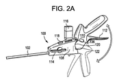
開示内容が参照により本明細書に組み込まれる、本願と同一譲受人に譲渡された米国特許第8,920,439号は、近位シャフト部及び遠位シャフト部を含む細長シャフトを有する外科用締結具を供給するためのアプリケータ器具を開示している。アプリケータ器具は、遠位シャフト部と近位シャフト部との間の角度を選択的に変更するために、遠位シャフト部と連結された関節運動コントローラを有する。関節運動コントローラは、シャフトを通って延在する少なくとも1つの柔軟性リンク機構を有し、アクチュエータと接続された近位端と、遠位シャフト部と接続された遠位端とを有する。アクチュエータはハウジングに取り付けられており、少なくとも1つの柔軟性リンク機構を近位方向及び遠位方向に移動させるために、ハウジングの近位端と遠位端との間で摺動する。外科用締結具は、細長シャフトの遠位端から1つずつ供給されるように、細長シャフト内に配置される。 U.S. Pat. No. 8,920,439, assigned to the same assignee as the present application, the disclosure of which is incorporated herein by reference, is a surgical conclusion with an elongated shaft that includes a proximal shaft portion and a distal shaft portion. Discloses applicator equipment for supplying ingredients. The applicator instrument has a range of motion controller coupled to the distal shaft portion to selectively change the angle between the distal shaft portion and the proximal shaft portion. The range of motion controller has at least one flexible link mechanism extending through the shaft, having a proximal end connected to an actuator and a distal end connected to a distal shaft portion. The actuator is mounted on the housing and slides between the proximal and distal ends of the housing to move at least one flexible linkage in the proximal and distal directions. Surgical fasteners are placed within the elongated shaft so that they are supplied one by one from the distal end of the elongated shaft.
上記の進歩にもかかわらず、腹腔鏡手術中の術中状態は、外科医にとって困難なままである。外科医の人間工学及び締結具の選択肢の両方に対する柔軟性の必要性が存在する。人間工学に関して、同側(同じ側の)メッシュ張力付与を可能にし、体腔の内側及び外側の両方の操作性を提供する、人間工学的に改善された外科用締結具を供給するためのアプリケータ器具が依然として必要とされている。また、シャフトが関節運動しているときに最適な遠位シャフト強度を有し、装置の複雑性及びユーザエクスペリエンスを単純化する予め定義された関節運動角度を提供する、外科用締結具を供給するためのアプリケータ器具も依然として必要とされている。正中線及び横方向トロカール配置の両方を含む多様な範囲のトロカール配置を適合させるための、改善された人間工学を有するアプリケータ器具も依然として必要とされている。加えて、患者の多様なニーズに応えるように調整された締結具の解決法が必要とされている。更に、この必要性に関連して、外科処置中の処置コストを低減し、柔軟性を高める必要がある。 Despite the above advances, the intraoperative condition during laparoscopic surgery remains difficult for the surgeon. There is a need for flexibility in both the surgeon's ergonomics and fastener choices. For ergonomics, an applicator to provide ergonomically improved surgical fasteners that allow ipsilateral (ipsilateral) mesh tensioning and provide maneuverability both inside and outside the body cavity. Equipment is still in need. It also provides surgical fasteners that have optimal distal shaft strength when the shaft is in range of motion and provide a predefined range of motion angle that simplifies device complexity and user experience. Applicator equipment for the purpose is still needed. There is still a need for applicator instruments with improved ergonomics to accommodate a diverse range of trocar configurations, including both median and lateral trocar configurations. In addition, there is a need for fastener solutions that are tailored to meet the diverse needs of patients. In addition, in connection with this need, there is a need to reduce treatment costs and increase flexibility during surgical procedures.
一実施形態では、外科用締結具を供給するためのアプリケータ器具は、好ましくは、ハウジングと、ハウジングの遠位端から延在する細長シャフトであって、近位シャフト部及び関節運動遠位シャフト部を有する細長シャフトと、ハウジング内に配置された発射システムと、発射システムの発射サイクルを開始するように係合可能であるアクチュエータと、細長シャフトの関節運動遠位シャフト部を選択的に関節運動させるための、ハウジング上に提供された関節運動レバーとを備える。 In one embodiment, the applicator instrument for supplying the surgical fastener is preferably a housing and an elongated shaft extending from the distal end of the housing, a proximal shaft portion and a joint motion distal shaft. An elongated shaft with a portion, a launch system located within a housing, an actuator that is engageable to initiate the launch cycle of the launch system, and a joint motion of the elongated shaft. It is equipped with a joint movement lever provided on the housing for allowing.
一実施形態では、アプリケータ器具は、好ましくは、関節運動遠位シャフト部と結合され、関節運動遠位シャフト部を真っ直ぐにするための第1の位置(例えば、水平位置)と、関節運動遠位シャフト部を関節運動させるための第2の位置(例えば、垂直位置)との間で関節運動レバーによって回転されるように関節運動レバーと連結された、ハウジング内に配置されたカムプレートを有する。一実施形態では、オーバーセンターアセンブリが、関節運動遠位シャフト部を真っ直ぐにするための第1の位置又は関節運動遠位シャフト部を関節運動させるための第2の位置のいずれかにカムプレートを押し込むように、カムプレートと連結される。 In one embodiment, the applicator device is preferably coupled to a joint motion distal shaft portion with a first position (eg, horizontal position) for straightening the joint motion distal shaft portion and a joint motion distance. It has a cam plate arranged in a housing connected to the joint movement lever so as to be rotated by the joint movement lever to and from a second position (for example, a vertical position) for joint movement of the position shaft portion. .. In one embodiment, the overcenter assembly places the cam plate in either a first position for straightening the distal shaft of joint movement or a second position for jointly moving the distal shaft of joint movement. It is connected to the cam plate so that it can be pushed in.
一実施形態では、アプリケータ器具は、ハウジング内に配置された回転可能なヨークを備えてもよい。一実施形態では、回転可能なヨークは、カムプレートが第1の位置と第2の位置との間で回転する際に、カムプレートによって回転されるようにカムプレートと連結される。一実施形態では、上部スライダは、近位シャフト部の頂部側上に位置付けられ、回転可能なヨークの上端に接続され、上部関節運動バンドは、上部スライダに接続された近位端を有する。一実施形態では、上部関節運動バンドは、望ましくは、細長シャフトを通って延在する長さ、及び関節運動遠位シャフト部に固定された遠位端を有する。一実施形態では、下部スライダは、近位シャフト部の底部側の下に位置付けられ、回転可能なヨークの下端に接続される。一実施形態では、下部関節運動バンドは、下部スライダに接続された近位端、細長シャフトを通って延在する長さ、及び関節運動遠位シャフト部に固定された遠位端を有する。 In one embodiment, the applicator appliance may include a rotatable yoke located within the housing. In one embodiment, the rotatable yoke is coupled to the cam plate so that it is rotated by the cam plate as it rotates between the first and second positions. In one embodiment, the upper slider is located on the apical side of the proximal shaft portion and is connected to the upper end of a rotatable yoke, and the upper range of motion band has a proximal end connected to the upper slider. In one embodiment, the upper range of motion band preferably has a length extending through an elongated shaft and a distal end fixed to a portion of the distal range of motion. In one embodiment, the lower slider is located below the bottom side of the proximal shaft portion and is connected to the lower end of the rotatable yoke. In one embodiment, the lower range of motion band has a proximal end connected to a lower slider, a length extending through an elongated shaft, and a distal end fixed to a portion of the distal range of motion.
一実施形態では、アプリケータ器具は、上部関節運動バンドに対する張力を調節するように、上部スライダを回転可能なヨークの上端と接続する上部張力調節アセンブリと、下部関節運動バンドに対する張力を調節するように、下部スライダを回転可能なヨークの下端と接続する下部張力調節アセンブリとを備えてもよい。 In one embodiment, the applicator device adjusts the tension on the lower range of motion band with the upper tension adjusting assembly that connects the upper slider to the upper end of the rotatable yoke so as to adjust the tension on the upper range of motion band. May include a lower tension adjusting assembly that connects the lower slider to the lower end of the rotatable yoke.
一実施形態では、近位シャフト部は、望ましくは、近位端と、遠位端と、その近位端から遠位端まで延在する長手方向軸とを有する。一実施形態では、回転可能なヨークは、近位シャフト部の長手方向軸に対して回転するように、近位シャフト部の近位端に枢動可能に固定されている。 In one embodiment, the proximal shaft portion preferably has a proximal end, a distal end, and a longitudinal axis extending from the proximal end to the distal end thereof. In one embodiment, the rotatable yoke is pivotally secured to the proximal end of the proximal shaft portion so as to rotate with respect to the longitudinal axis of the proximal shaft portion.
一実施形態では、回転可能なヨークは、中央開口部を有し、近位シャフト部の近位端は、回転可能なヨークの中央開口部を通過する。 In one embodiment, the rotatable yoke has a central opening and the proximal end of the proximal shaft portion passes through the central opening of the rotatable yoke.
一実施形態では、カムプレートが第1の位置にあるとき、ヨークの上端は、ヨークの下端の遠位にある。一実施形態では、カムプレートが第2の位置にあるとき、ヨークの上端は、ヨークの下端の近位にある。 In one embodiment, the upper end of the yoke is distal to the lower end of the yoke when the cam plate is in the first position. In one embodiment, when the cam plate is in the second position, the upper end of the yoke is proximal to the lower end of the yoke.
一実施形態では、近位シャフト部は、近位シャフト部の近位端において近位シャフト部の頂部側に形成された上部スロットを含備えてもよい。一実施形態では、上部関節運動バンドの近位端は、上部スロットにおいて上部スライダに取り付けられている。 In one embodiment, the proximal shaft portion may include an upper slot formed on the apical side of the proximal shaft portion at the proximal end of the proximal shaft portion. In one embodiment, the proximal end of the upper range of motion band is attached to the upper slider in the upper slot.
一実施形態では、近位シャフト部の近位端において近位シャフト部の底部側に下部スロットが形成される。一実施形態では、下部関節運動バンドの近位端は、下部スロットにおいて下部スライダに取り付けられている。 In one embodiment, a lower slot is formed on the bottom side of the proximal shaft portion at the proximal end of the proximal shaft portion. In one embodiment, the proximal end of the lower range of motion band is attached to the lower slider in the lower slot.
一実施形態では、上部スロットは、近位シャフト部の近位端に対する上部スライダの遠位及び近位摺動運動を誘導する、対向する横方向縁部を有する。一実施形態では、下部スロットは、近位シャフト部の近位端に対する下部スライダの遠位及び近位摺動運動を誘導する、対向する横方向縁部を有する。 In one embodiment, the upper slot has opposed lateral edges that guide distal and proximal sliding movements of the upper slider with respect to the proximal end of the proximal shaft portion. In one embodiment, the lower slot has opposed lateral edges that guide distal and proximal sliding movements of the lower slider with respect to the proximal end of the proximal shaft portion.
一実施形態では、オーバーセンターアセンブリは、ハウジングに枢動可能に取り付けられた上部支柱と、カムプレートに枢動可能に取り付けられた下部支柱と、上部支柱と下部支柱との間に拘束された圧縮ばねとを備えてもよい。一実施形態では、カムプレートが第1の位置にあるとき、圧縮ばねは、カムプレートを第1の位置に留まるように付勢し、カムプレートが第2の位置にあるとき、圧縮ばねは、カムプレートを第2の位置に留まるように付勢する。 In one embodiment, the overcenter assembly is a compression constrained between an upper strut pivotally attached to the housing, a lower strut pivotally attached to a cam plate, and an upper strut and a lower strut. It may be provided with a spring. In one embodiment, when the cam plate is in the first position, the compression spring urges the cam plate to stay in the first position, and when the cam plate is in the second position, the compression spring. Encourage the cam plate to stay in the second position.
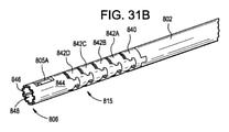
一実施形態では、関節運動遠位シャフト部は、望ましくは、一緒に結合され、互いに対して枢動するように適合された複数の関節運動セグメントを備える。 In one embodiment, the range of motion distal shafts preferably comprises multiple range of motion segments that are coupled together and adapted to pivot with respect to each other.
一実施形態では、関節運動セグメントは、好ましくは、近位シャフト部の遠位端に取り付けられた近位関節運動セグメントと、近位関節運動セグメントの遠位端と連結された複数の中間関節運動セグメントと、複数の中間関節運動セグメントの遠位端と連結されて、細長シャフトの最遠位端を画定する、遠位関節運動セグメントとを含む。 In one embodiment, the joint motion segment is preferably a proximal joint motion segment attached to the distal end of the proximal shaft portion and a plurality of intermediate joint motions linked to the distal end of the proximal joint motion segment. Includes a segment and a distal joint motion segment that is connected to the distal ends of multiple intermediate joint motion segments and defines the distal end of the elongated shaft.
一実施形態では、遠位関節運動セグメントは、その最遠位端に開口部を備え、開口部は、開口部を通して外科用締結具を供給するように適合されている。一実施形態では、上部関節運動バンド及び下部関節運動バンドは、遠位関節運動セグメントのそれぞれの上部及び下部に固定されるように、近位シャフト部、近位関節運動セグメント、及び中間関節運動セグメントを通過する。 In one embodiment, the distal range of motion segment has an opening at its most distal end, which is adapted to supply surgical fasteners through the opening. In one embodiment, the upper and lower range of motion bands are anchored to the upper and lower parts of the distal joint range of motion, respectively, in the proximal shaft, proximal joint motion segment, and intermediate joint motion segment. Pass through.
一実施形態では、各中間関節運動セグメントは、好ましくは、近位端と、遠位端と、上部関節運動バンドを据え付けるために近位端と遠位端との間に延在する上部チャネルと、下部関節運動バンドを据え付けるために近位端と遠位端との間に延在する下部チャネルと、その近位端と遠位端との間に延在する中央通路とを備える。 In one embodiment, each intermediate joint movement segment preferably has a proximal end, a distal end, and an upper channel extending between the proximal and distal ends for mounting the upper joint movement band. It comprises a lower channel extending between the proximal and distal ends for mounting the lower joint motion band and a central passage extending between the proximal and distal ends thereof.
一実施形態では、中間関節運動セグメントのうちの1つ又は2つ以上は、好ましくは、中間関節運動セグメントの遠位端において中間関節運動セグメントの横側に形成された一対のT字形開口部を有する。一実施形態では、T字形開口部の各々は、中間関節運動セグメントの遠位端に面する凹面を有してもよい。 In one embodiment, one or more of the intermediate joint movement segments preferably have a pair of T-shaped openings formed laterally of the intermediate joint movement segment at the distal end of the intermediate joint movement segment. Have. In one embodiment, each of the T-shaped openings may have a concave surface facing the distal end of the intermediate range of motion segment.
一実施形態では、中間関節運動セグメントのうちの1つ又は2つ以上は、好ましくは、中間関節運動セグメントの近位端において中間関節運動セグメントの横側に形成された一対のT字形突出部を有する。一実施形態では、各T字形突出部は、望ましくは、中間関節運動セグメントの近位端に面する凸面を有する。 In one embodiment, one or more of the intermediate joint movement segments preferably have a pair of T-shaped protrusions formed laterally of the intermediate joint movement segment at the proximal end of the intermediate joint movement segment. Have. In one embodiment, each T-shaped protrusion preferably has a convex surface facing the proximal end of the intermediate range of motion segment.
一実施形態では、中間関節運動セグメントの遠位側のセグメントのT字形突出部は、隣接する中間関節運動セグメントを一緒に結合するために、中間関節運動セグメントの近位側のセグメントのT字形開口部内に据え付けられる。一実施形態では、関節運動中、T字形突出部は、隣接する中間関節運動セグメントの互いに対する枢動運動を制限するために、T字形開口部の縁部に接触する。 In one embodiment, the T-shaped protrusion of the distal segment of the intermediate joint motion segment is a T-shaped opening of the proximal segment of the intermediate joint motion segment to join adjacent intermediate joint motion segments together. It is installed in the department. In one embodiment, during range of motion, the T-shaped protrusion contacts the edge of the T-shaped opening to limit the pivotal movement of adjacent intermediate joint movement segments with respect to each other.
一実施形態では、関節運動レバーを垂直位置に移動させることは、カムプレートを時計回りの方向に回転させ、そうするとオーバーセンターアセンブリが、カムプレートを第2の位置に留まるように付勢する。一実施形態では、関節運動制御レバーを水平位置に移動させることは、カムプレートを反時計回りの方向に回転させ、そうするとオーバーセンターアセンブリが、カムプレートを第1の位置に留まるように付勢する。 In one embodiment, moving the range of motion lever to a vertical position rotates the cam plate in a clockwise direction so that the overcenter assembly urges the cam plate to stay in the second position. In one embodiment, moving the joint motion control lever to a horizontal position rotates the cam plate in a counterclockwise direction so that the overcenter assembly urges the cam plate to stay in the first position. ..
一実施形態では、カムプレートの時計回りの回転は、ヨークの時計回りの回転をもたらし、これが次に、関節運動遠位シャフト部を関節運動させるための上部関節運動バンドにおける張力を増加させるために、上部スライダを近位方向に移動させる。 In one embodiment, the clockwise rotation of the cam plate results in a clockwise rotation of the yoke, which in turn increases tension in the upper joint motion band for joint motion of the distal shaft portion of joint motion. , Move the top slider in the proximal direction.
一実施形態では、カムプレートが第1の位置にあるとき、上部スライダ及び下部スライダは、近位シャフト部の長手方向軸に沿って互いに一直線になり、回転可能なヨークの上端は、好ましくは、回転可能なヨークの下端の遠位にある。 In one embodiment, when the cam plate is in the first position, the upper and lower sliders are aligned with each other along the longitudinal axis of the proximal shaft portion, and the upper end of the rotatable yoke is preferably preferred. Distal of the lower end of the rotatable yoke.
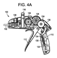
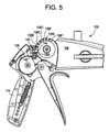
一実施形態では、外科用締結具を供給するためのアプリケータ器具は、好ましくは、ハウジングと、ハウジングの遠位端から延在する細長シャフトであって、近位シャフト部及び関節運動遠位シャフト部を有する、細長シャフトと、ハウジング上に提供された関節運動レバーと、ハウジングの近位端と連結されたハンドルと、ハンドルと連結されたトリガと、ハウジング内に配置された発射システムであって、エネルギー貯蔵アセンブリを含む、発射システムと、ハンドル内に配置され、トリガと連結されたギアトレーンとを備え、トリガは、エネルギー貯蔵アセンブリ内にエネルギーを貯蔵するために引くことが可能である。一実施形態では、カムプレートは、ハウジング内に配置され、関節運動遠位シャフト部と結合される。一実施形態では、カムプレートは、望ましくは、関節運動遠位シャフト部を真っ直ぐにするための第1の位置と、関節運動遠位シャフト部を関節運動させるための第2の位置との間で関節運動レバーによって回転されるように、関節運動レバーと連結される。一実施形態では、オーバーセンターアセンブリは、好ましくは、関節運動遠位シャフト部を真っ直ぐにすることと関連した第1の位置又は関節運動遠位シャフト部を関節運動させることと関連した第2の位置のいずれかにカムプレートを押し込むように、カムプレートと連結される。 In one embodiment, the applicator instrument for supplying the surgical fastener is preferably a housing and an elongated shaft extending from the distal end of the housing, a proximal shaft portion and a joint motion distal shaft. An elongated shaft with parts, a joint movement lever provided on the housing, a handle connected to the proximal end of the housing, a trigger connected to the handle, and a launch system located within the housing. Equipped with a launch system, including an energy storage assembly, and a gear train located in the handle and coupled with a trigger, the trigger can be pulled to store energy within the energy storage assembly. In one embodiment, the cam plate is placed within the housing and coupled to the range of motion distal shaft portion. In one embodiment, the cam plate is preferably between a first position for straightening the distal shaft portion of joint movement and a second position for joint movement of the distal shaft portion of joint movement. It is connected to the joint movement lever so that it is rotated by the joint movement lever. In one embodiment, the overcenter assembly is preferably a first position associated with straightening the range of motion distal shaft or a second position associated with range of motion distal shaft. It is connected to the cam plate so as to push the cam plate into one of the above.
一実施形態では、外科用締結具を供給するためのアプリケータ器具は、望ましくは、ハウジングと、ハウジングの遠位端から延在する細長シャフトであって、近位シャフト部及び関節運動遠位シャフト部を有する、細長シャフトと、ハウジング上に提供された関節運動レバーと、ハウジングの近位端と連結されたハンドルと、ハンドルと連結されたトリガと、ハウジング内に配置された発射システムであって、エネルギー貯蔵アセンブリを含む、発射システムと、ハンドル内に配置され、トリガと連結されたギアトレーンであって、エネルギー貯蔵アセンブリ内にエネルギーを貯蔵するために、トリガが引くことが可能である、ギアトレーンと、を備える。一実施形態では、カムプレートは、ハウジング内に配置され、関節運動遠位シャフト部と結合され、関節運動遠位シャフト部を真っ直ぐにするための第1の位置と、関節運動遠位シャフト部を関節運動させるための第2の位置との間で関節運動レバーによって回転されるように、関節運動レバーと連結される。一実施形態では、オーバーセンターアセンブリは、好ましくは、関節運動遠位シャフト部を真っ直ぐにすることと関連した第1の位置又は関節運動遠位シャフト部を関節運動させることと関連した第2の位置のいずれかにカムプレートを押し込むように、カムプレートと連結される。一実施形態では、アプリケータ器具は、好ましくは、ハンドルをハウジングに対して定位置にロックするための第1の位置、及びハンドルがピストル構成とインライン構成との間でハウジングに対して回転することを可能にするための第2の位置を有する、ハンドル再構成アクチュエータを備える。 In one embodiment, the applicator instrument for supplying surgical fasteners is preferably a housing and an elongated shaft extending from the distal end of the housing, a proximal shaft portion and a joint motion distal shaft. An elongated shaft with parts, a joint motion lever provided on the housing, a handle connected to the proximal end of the housing, a trigger connected to the handle, and a launch system located within the housing. A gear train that is located in the handle and coupled with a trigger, including an energy storage assembly, and a gear in which the trigger can be pulled to store energy in the energy storage assembly. Equipped with a train. In one embodiment, the cam plate is located within the housing and is coupled to the distal joint motion shaft to provide a first position for straightening the distal joint motion shaft and the distal joint motion shaft. It is connected to the joint movement lever so that it is rotated by the joint movement lever to and from the second position for joint movement. In one embodiment, the overcenter assembly is preferably a first position associated with straightening the range of motion distal shaft or a second position associated with range of motion distal shaft. It is connected to the cam plate so as to push the cam plate into one of the above. In one embodiment, the applicator appliance preferably has a first position for locking the handle in place with respect to the housing, and the handle rotates with respect to the housing between the pistol configuration and the in-line configuration. It comprises a handle reconstruction actuator having a second position to enable.
一実施形態では、外科処置中に外科用締結具を供給するためのアプリケータ器具は、ピストル構成と、インライン構成と、反転ピストルとの間で移動し得る再構成可能なハンドルを有する。再構成可能なハンドルを有するアプリケータ器具は、人間工学及び器具操作性が重要であるヘルニア修復処置などの腹腔鏡下手術中に特に有用である。 In one embodiment, the applicator instrument for supplying surgical fasteners during a surgical procedure has a pistol configuration, an in-line configuration, and a reconfigurable handle that can be moved between the inverted pistol. Applicator instruments with reconfigurable handles are particularly useful during laparoscopic surgery such as hernia repair procedures where ergonomics and instrument operability are important.
一実施形態では、アプリケータ器具は、遠位ハウジングアセンブリと、近位ハンドルアセンブリと、遠位ハウジングアセンブリと近位ハンドルアセンブリとの間の枢動接続部と、遠位ハウジングアセンブリ及び近位ハンドルアセンブリを互いに対して複数の角度位置で固定するためのロック要素とを備える。 In one embodiment, the applicator instrument comprises a distal housing assembly, a proximal handle assembly, a pivotal connection between the distal housing assembly and the proximal handle assembly, and a distal housing assembly and a proximal handle assembly. It is provided with a locking element for fixing the members at a plurality of angular positions with respect to each other.
一実施形態では、ロック要素は、近位ハンドルアセンブリが遠位ハウジングアセンブリを中心に枢動することを可能にするために係合され得る、近位ハンドルアセンブリ上に位置するボタンを含む。近位ハンドルアセンブリは、ピストル構成、インライン構成、又は反転ピストル構成を含む、ハウジングアセンブリに対して複数の位置に配置され得るように再構成可能である。一実施形態では、近位ハンドルアセンブリは、90~180度の角度範囲で調節され得る。 In one embodiment, the locking element comprises a button located on the proximal handle assembly that can be engaged to allow the proximal handle assembly to pivot around the distal housing assembly. The proximal handle assembly can be reconfigured so that it can be placed in multiple positions with respect to the housing assembly, including a pistol configuration, an inline configuration, or an inverted pistol configuration. In one embodiment, the proximal handle assembly can be adjusted in an angular range of 90-180 degrees.
一実施形態では、アプリケータ器具は、望ましくは、外科用締結具を供給するための発射システムを作動させるために使用されるギアトレーンを備える。一実施形態では、ギアトレーンは、好ましくは、発射システムを作動させるために、遠位ハウジングアセンブリ内に位置するギアトレーンの第2の部分と係合するように構成された、近位ハンドルアセンブリ内に位置するギアトレーンの第1の部分を含む。一実施形態では、遠位ハウジングアセンブリ内の少なくとも1つのギアは、再構成ピボットの回転軸と同心である。 In one embodiment, the applicator instrument preferably comprises a gear train used to actuate a launch system for supplying surgical fasteners. In one embodiment, the gear train is preferably within a proximal handle assembly configured to engage a second portion of the gear train located within the distal housing assembly to actuate the launch system. Includes the first part of the gear train located at. In one embodiment, at least one gear in the distal housing assembly is concentric with the axis of rotation of the reconstructed pivot.
一実施形態では、近位ハンドルアセンブリは、ギアトレーンを起動するために引かれ得るトリガを有する。一実施形態では、遠位ハウジングアセンブリに対する近位ハンドルアセンブリの再構成中、近位ハンドルアセンブリ内のギアトレーンは、遠位ハウジングアセンブリ内のギア/ギアトレーンから係合解除されて、トリガ/ギアトレーンのストロークに影響を及ぼさずに再構成を可能にする。 In one embodiment, the proximal handle assembly has a trigger that can be pulled to activate the gear train. In one embodiment, during the reconstruction of the proximal handle assembly relative to the distal housing assembly, the gear train in the proximal handle assembly is disengaged from the gear / gear train in the distal housing assembly to trigger / gear train. Allows reconstruction without affecting the stroke of.
一実施形態では、発射サイクルを開始するためにトリガが引かれたとき、再構成ボタンは、発射サイクル中に遠位ハウジングアセンブリに対する近位ハンドルアセンブリの再構成を防止するように遮断される。 In one embodiment, when the trigger is pulled to initiate the firing cycle, the reconfiguration button is blocked to prevent reconstruction of the proximal handle assembly relative to the distal housing assembly during the firing cycle.
一実施形態では、遠位ハウジングアセンブリに対して近位ハンドルアセンブリの角度を変化させるために再構成ボタンが押し下げられると、近位ハンドルアセンブリの再構成を完了する前に、トリガ又はギアトレーンが遮断されてアプリケータ器具の発射を防止する。 In one embodiment, when the reconfiguration button is pressed to change the angle of the proximal handle assembly with respect to the distal housing assembly, the trigger or gear train shuts off before completing the reconstruction of the proximal handle assembly. Being prevented from firing applicator equipment.
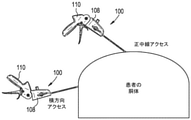
本発明は、動作のいかなる特定の理論にも制限されないが、再構成可能なハンドルを有するアプリケータ器具を提供することは、外科処置の人間工学を改善し、器具の操作性を改善すると考えられる。例えば、トロカールが典型的には患者の正中線の近くに配置され、外科医が典型的には患者の上に器具を保持するような姿勢を取るため、ピストル構成は、完全腹膜外(Totally Extra-Peritoneal、TEP)鼠経修復処置にとって好ましくあり得る。対照的に、ピストル構成又はインライン構成のいずれかは、経腹的腹膜前(Trans-Abdominal Pre-Peritoneal、TAPP)鼠径及び腹側修復にとって好ましくあり得る。これらの修復の両方に関して、トロカールは、典型的には、患者の側面の近くに配置され(即ち、横方向配置)、外科医は、患者の身体にわたって作業することになる。反対側では、ピストル構成又はインライン構成のいずれかが有利であり得る。しかしながら、同側では、インライン位置は、外科医が、発射直前に遠位端に予荷重を提供するために装置を活用しながら、中立の手首位置を維持することを可能にする利点を提供する。 The present invention is not limited to any particular theory of motion, but providing an applicator instrument with a reconfigurable handle is believed to improve the ergonomics of the surgical procedure and improve the operability of the instrument. .. For example, the pistol configuration is Totally Extra-because the trocar is typically placed near the patient's midline and the surgeon is typically in a position to hold the instrument over the patient. Peritoneal, TEP) may be preferred for inguinal repair procedures. In contrast, either a pistol or in-line configuration may be preferred for trans-Abdominal Pre-Peritoneal (TAPP) inguinal and ventral repair. For both of these repairs, the trocar is typically placed near the side of the patient (ie, laterally placed) and the surgeon will work across the patient's body. On the other side, either a pistol configuration or an inline configuration can be advantageous. However, on the ipsilateral side, the in-line position provides the advantage of allowing the surgeon to maintain a neutral wrist position while leveraging the device to provide preload to the distal end just prior to launch.
したがって、一実施形態では、再構成可能なハンドルを有する単一のアプリケータ器具が、正中線及び横方向トロカール配置のために使用され、汎用性及び改善された人間工学を提供することができる。 Thus, in one embodiment, a single applicator device with a reconfigurable handle can be used for midline and lateral trocar placement to provide versatility and improved ergonomics.
一実施形態では、カートリッジは、カートリッジ内で互いの上に積み重ねられ、ばねによってカートリッジの下端に向かって付勢される、複数の外科用締結具を収容する。一実施形態では、アプリケータは、異なるタイプの外科用締結具を有する異なるカートリッジと共に使用され得る。一実施形態では、アプリケータ器具は、異なるカートリッジを受容するように適合されたアプリケータ器具の近位端に位置するカートリッジ受容ポートを有してもよい。一実施形態では、アプリケータ器具の細長シャフトが患者の内部に留まっている状態で、異なるカートリッジは、第1のタイプの外科用締結具が第1の発射サイクル中に発射され得、第2のタイプの外科用締結具が第2の発射サイクル中に発射され得るように、発射サイクル間で交換され得る。アプリケータ器具の遠位端を患者から取り外すことなくカートリッジを交換する能力は、好ましくは、効率性、安全性を強化し、滅菌状態を維持する。 In one embodiment, the cartridges accommodate a plurality of surgical fasteners that are stacked on top of each other within the cartridge and urged by a spring toward the lower end of the cartridge. In one embodiment, the applicator can be used with different cartridges with different types of surgical fasteners. In one embodiment, the applicator device may have a cartridge receiving port located at the proximal end of the applicator device adapted to receive different cartridges. In one embodiment, with the elongated shaft of the applicator instrument remaining inside the patient, different cartridges can be fired by a first type of surgical fastener during the first firing cycle, a second. The type of surgical fastener can be exchanged between firing cycles so that it can be fired during the second firing cycle. The ability to replace the cartridge without removing the distal end of the applicator instrument from the patient preferably enhances efficiency, safety and maintains sterility.
一実施形態では、再構成可能なハンドルは存在しない。代わりに、遠位ハウジングアセンブリは、外科用ロボットのアームに直接ドッキングされる。次いで、外科用ロボットは、ロボットアーム上の標準的なインターフェースを介して関節運動及び発射機能を制御する。ユーザは、なおもカートリッジを交換し、新しいカートリッジをハウジングアセンブリに取り付けることができる。このようにして、器具は、ロボットアームに取り付けられたアプリケータ器具を交換することなく、様々な外科用締結具を送達するために再装填又は使用され得る。 In one embodiment, there are no reconfigurable handles. Instead, the distal housing assembly is docked directly to the arm of the surgical robot. The surgical robot then controls joint motion and launch function via a standard interface on the robot arm. The user can still replace the cartridge and install the new cartridge in the housing assembly. In this way, the instrument can be reloaded or used to deliver a variety of surgical fasteners without having to replace the applicator instrument attached to the robot arm.
一実施形態では、近位ハンドルアセンブリは、遠位ハウジングアセンブリ上に位置する再構成ノッチを係合するように構成された再構成スライダが連結された、再構成ボタンを有する。一実施形態では、再構成ボタンが押し下げられると、再構成スライダは、再構成スロットのうちの1つとの係合から離れて移動し、これにより近位ハンドルアセンブリは、遠位ハウジングアセンブリに対して枢動し得る。再構成ボタンが解放されると、スライダばねは通常、スライダを付勢してロック位置に戻す。一実施形態では、ハンドルの再構成中、ハンドルとハウジングとの間のギアトレーンは、分離される。 In one embodiment, the proximal handle assembly has a reconstruction button to which a reconstruction slider configured to engage a reconstruction notch located on the distal housing assembly is connected. In one embodiment, when the reconstruction button is pressed, the reconstruction slider moves away from engagement with one of the reconstruction slots so that the proximal handle assembly is relative to the distal housing assembly. Can be pivotal. When the reconfigure button is released, the slider spring normally urges the slider back to its locked position. In one embodiment, the gear train between the handle and the housing is separated during the reconstruction of the handle.
一実施形態では、再構成ボタンが押し下げられると、展開された再構成ボタンは、トリガの起動又は発射サイクルの開始を遮断する。したがって、一実施形態では、アプリケータ器具は、ハンドルの位置が再構成されているときに発射されなくてもよい。 In one embodiment, when the reconfiguration button is pressed down, the deployed reconfiguration button blocks the trigger activation or the start of the firing cycle. Thus, in one embodiment, the applicator device does not have to be fired when the position of the handle is being reconfigured.
一実施形態では、ギアトレーンを移動させるか、又は発射サイクルを開始するためにトリガが引かれると、展開されたトリガは、ハンドル再構成アクチュエータ(例えば、押圧可能な要素又はボタン)が移動する(例えば、押し下げられる)ことを防止する。したがって、一実施形態では、ハンドルの位置は、アプリケータ器具が発射されているとき、又は発射サイクルの開始後に再構成されなくてもよい。 In one embodiment, when the trigger is pulled to move the gear train or initiate a firing cycle, the deployed trigger moves the handle reconstructing actuator (eg, a pressable element or button) (eg, a pressable element or button). For example, it is prevented from being pushed down. Thus, in one embodiment, the position of the handle does not have to be reconfigured when the applicator device is being fired or after the start of the firing cycle.
一実施形態では、外科用締結具を供給するためのアプリケータ器具は、器具の近位端又はその近くの位置から単一の外科用締結具に係合し、外科用締結具を器具の遠位端に前進させる。一実施形態では、ばねなどの駆動要素は、所定の力を提供し、外科用締結具の一貫した送達をもたらす。発射の過程にわたって、この力は、締結具を加速させ、その速度及び運動量を高め、締結具が様々なメッシュ及び組織を貫通することを可能にする。 In one embodiment, the applicator instrument for supplying the surgical fastener engages a single surgical fastener from a position at or near the proximal end of the instrument and the surgical fastener is far away from the instrument. Advance to the end. In one embodiment, a driving element such as a spring provides a predetermined force, resulting in consistent delivery of the surgical fastener. Throughout the firing process, this force accelerates the fasteners, increasing their velocity and momentum, allowing the fasteners to penetrate various meshes and tissues.
一実施形態では、外科用締結具を送達するためのアプリケータ器具は、好ましくは、近位端及び遠位端を有する細長シャフトなどの細長部材と、細長部材の近位端に隣接して位置する外科用締結具(例えば、組織締結具又は外科用ステープル)と、細長部材の近位端から細長部材の遠位端に、かつ組織の中へと外科用締結具を運ぶための機構とを備える。 In one embodiment, the applicator instrument for delivering the surgical fastener is preferably located adjacent to an elongated member, such as an elongated shaft having proximal and distal ends, and the proximal end of the elongated member. A surgical fastener (eg, a tissue fastener or a surgical staple) and a mechanism for carrying the surgical fastener from the proximal end of the elongated member to the distal end of the elongated member and into the tissue. Be prepared.
一実施形態では、アプリケータ器具は、好ましくは、1つ又は2つ以上の外科用締結具を保持するカートリッジを備える。一実施形態では、複数の外科用締結具は、ばね荷重されたカートリッジ内で互いの上に又は互いに隣接して積層される。一実施形態では、カートリッジは、細長部材の近位端に隣接して位置付けられてもよい。 In one embodiment, the applicator instrument preferably comprises a cartridge that holds one or more surgical fasteners. In one embodiment, the plurality of surgical fasteners are stacked on top of each other or adjacent to each other in a spring loaded cartridge. In one embodiment, the cartridge may be positioned adjacent to the proximal end of the elongated member.
一実施形態では、アプリケータ器具は、好ましくは、カートリッジによって保持された単一の外科用締結具に係合するための要素を備え、これにより、単体化された外科用締結具は、発射システムによって係合され得、かつ/又は細長部材の遠位端に向かって前進し得る。一実施形態では、単一の外科用締結具は、外科用締結具の積み重ね体の底部から剥ぎ取られてもよい。 In one embodiment, the applicator instrument preferably comprises an element for engaging a single surgical fastener held by a cartridge, whereby a single surgical fastener is a launch system. Can be engaged by and / or can advance towards the distal end of the elongated member. In one embodiment, the single surgical fastener may be stripped from the bottom of the stack of surgical fasteners.
一実施形態では、アプリケータ器具は、望ましくは、細長部材の近位端から細長部材の遠位端まで外科用締結具を運ぶための遠位端を有する可撓性部材を有する。一実施形態では、可撓性部材は、プラスチック、金属、他の好適な材料、及び/又はこれらの組み合わせで作製されてもよい。一実施形態では、可撓性部材は、可撓性部材の柱強度を高めるために、断面が平面状であってもよく、又は断面が湾曲していてもよい。 In one embodiment, the applicator instrument preferably has a flexible member having a distal end for carrying the surgical fastener from the proximal end of the elongated member to the distal end of the elongated member. In one embodiment, the flexible member may be made of plastic, metal, other suitable materials, and / or a combination thereof. In one embodiment, the flexible member may have a planar cross section or a curved cross section in order to increase the column strength of the flexible member.
一実施形態では、可撓性部材は、外科用締結具を遠位方向に押す遠位端を有する。一実施形態では、可撓性部材は、好ましくは、格納され、コイル状に(例えば、収納用リール上に)収納され得る近位端を有する。一実施形態では、可撓性部材は、駆動ホイールと係合するための特徴を有してもよい。これらの特徴は、穴、ポケット、又は突出部であってもよい。一実施形態では、1つ又は2つ以上の駆動ホイールは、可撓性部材と摩擦係合するように設計された表面を有してもよい。 In one embodiment, the flexible member has a distal end that pushes the surgical fastener distally. In one embodiment, the flexible member preferably has a proximal end that can be stowed and stowed in a coil (eg, on a stowed reel). In one embodiment, the flexible member may have features for engaging with the drive wheel. These features may be holes, pockets, or protrusions. In one embodiment, the one or more drive wheels may have a surface designed to frictionally engage the flexible member.
一実施形態では、アプリケータ器具は、望ましくは、可撓性部材の遠位端の近位にある可撓性部材の部分に係合する駆動ホイール(例えば、歯車付きホイール又は摩擦ホイール)を有する。一実施形態では、駆動ホイールは、定トルクばね、トーションばね、電動モータ、機械的によって、電気的に、電気機械的に、及び/若しくは空気圧で、又は上記の組み合わせによって駆動されてもよい。一実施形態では、駆動ホイールは、例えば、ロボット手術システムのアームからの回転運動によって、又は圧縮空気によって駆動されてもよい。一実施形態では、駆動ホイールは、予め巻かれたばねなどの蓄積エネルギーシステムによって駆動されてもよい。 In one embodiment, the applicator appliance preferably has a drive wheel (eg, a geared wheel or a friction wheel) that engages a portion of the flexible member proximal to the distal end of the flexible member. .. In one embodiment, the drive wheel may be driven by a constant torque spring, torsion spring, electric motor, mechanically, electrically, electromechanically, and / or pneumatically, or by a combination of the above. In one embodiment, the drive wheel may be driven, for example, by rotary motion from the arm of a robotic surgery system or by compressed air. In one embodiment, the drive wheel may be driven by a stored energy system such as a pre-wound spring.
一実施形態では、可撓性部材は、定トルクばねに直接接続され、定トルクばねと連結された同じリール上に巻かれてもよく、したがって駆動ホイール構成要素を必要としない。一実施形態では、可撓性部材及び定トルクばねは、同じコイル上で一緒に層状になっていてもよい。 In one embodiment, the flexible member may be directly connected to a constant torque spring and wound on the same reel connected to the constant torque spring, thus eliminating the need for drive wheel components. In one embodiment, the flexible member and the constant torque spring may be layered together on the same coil.
一実施形態では、ぜんまいばね又は定トルクばねなどのばねは、可撓性部材の近位端に接続されて、可撓性部材を伸長位置から格納位置へと格納するのを補助し、かつ動作中に可撓性部材がリールから離れて膨らむことを防止するための張力を提供し得る。一実施形態では、膨らみは、好ましくは、システム内の抵抗又は損失を低減するために最小限に抑えられる。一実施形態では、定トルクばね又はトーションばねは、望ましくは、アプリケータ器具のハンドルと連結されたトリガ又はアクチュエータを引くことに応答して、エネルギーを蓄積する。 In one embodiment, a spring, such as a spring or constant torque spring, is connected to the proximal end of the flexible member to assist and operate in retracting the flexible member from the extended position to the retracted position. It may provide tension to prevent the flexible member from bulging away from the reel. In one embodiment, the bulge is preferably minimized to reduce resistance or loss in the system. In one embodiment, the constant torque spring or torsion spring preferably stores energy in response to pulling a trigger or actuator coupled to the handle of the applicator appliance.
一実施形態では、アプリケータ器具は、可撓性部材の遠位方向の移動を制限又は制御するために、可撓性部材又は駆動ホイールと連結された、又はそれに接触するポジティブストップを有してもよい。一実施形態では、ポジティブストップは、細長部材の遠位端、又はアプリケータ器具のハウジング部分内、又はその両方に位置してもよい。遠位停止部は、外科用締結具が装置の遠位端から延在する排出距離を正確に制御する利点を提供する。装置のハウジング端部の停止部は、可撓性部材、収納部材、又は駆動ホイールと直接係合することができる。駆動ホイールと係合された場合、停止部は、可撓性部材が伸長した状態で発射準備完了位置に置かれたときに、可撓性部材への圧縮荷重を低減する利点を提供することができる。あるいは、装置のハウジング端部の停止部は、収納リール又は可撓性部材と係合して、収納リールの過剰回転及びその後の可撓性部材の近位端への損傷を防止することができる。いずれの近位停止部に対しても、外科用締結具が組織に埋め込むのに十分なストロークを有するまで、停止部の係合を遅延させることが重要である。これはまた、可撓性部材の長さを圧縮し、近位停止部における衝撃を抑えるための時間を提供する。 In one embodiment, the applicator appliance has a positive stop connected to or in contact with the flexible member or drive wheel to limit or control the distal movement of the flexible member. May be good. In one embodiment, the positive stop may be located at the distal end of the elongated member and / or within the housing portion of the applicator device. The distal stop provides the advantage of precisely controlling the drainage distance that the surgical fastener extends from the distal end of the device. The stop at the end of the housing of the device can be directly engaged with a flexible member, storage member, or drive wheel. When engaged with the drive wheel, the stop may provide the advantage of reducing the compressive load on the flexible member when placed in the launch ready position with the flexible member extended. can. Alternatively, the stop at the end of the housing of the device can engage with the storage reel or flexible member to prevent excessive rotation of the storage reel and subsequent damage to the proximal end of the flexible member. .. For any proximal stop, it is important to delay the engagement of the stop until the surgical fastener has sufficient stroke to implant in the tissue. It also compresses the length of the flexible member and provides time to reduce the impact at the proximal stop.
一実施形態では、可撓性部材は、ガイド部材の拘束内で弾性的に圧縮及び座屈することが可能であり、それは好ましくは、外科用締結具に適用され得る力又はストロークを制限する。 In one embodiment, the flexible member is capable of elastically compressing and buckling within the constraints of the guide member, which preferably limits the force or stroke that can be applied to the surgical fastener.
一実施形態では、カートリッジは、細長シャフトの向きに対して、マガジン内の任意の角度(例えば、水平、垂直、又は中間の任意の角度)で積層された組織締結具を有してもよい。 In one embodiment, the cartridge may have tissue fasteners laminated at any angle within the magazine (eg, horizontal, vertical, or any intermediate angle) with respect to the orientation of the elongated shaft.
一実施形態では、外科用締結具は、可撓性部材を利用してカートリッジから単体化さされるか、又は剥ぎ取られてもよい。一実施形態では、可撓性部材の遠位端は、単一の外科用締結具をカートリッジから押して/剥ぎ取って、外科用締結具を単体化し、送達のためにカニューレ内に移動させる突出部分(例えば、固体又は圧縮性フィン)を含む。一実施形態では、挿入ツール又は挿入ガイドが可撓性部材の遠位端に取り付けられる。一実施形態では、挿入ツールは、可撓性部材及び挿入ツールが単一の構成要素であるような、可撓性部材の特徴である。挿入ツールは、外科用締結具を外科用締結具積み重ね体の底部から剥ぎ取るための、外科用締結具に係合するフィン又はストリッパランプを含んでもよい。 In one embodiment, the surgical fastener may be isolated or stripped from the cartridge using a flexible member. In one embodiment, the distal end of the flexible member is a protruding portion that pushes / strips a single surgical fastener from the cartridge to unify the surgical fastener and move it into the cannula for delivery. Includes (eg, solid or compressible fins). In one embodiment, an insertion tool or insertion guide is attached to the distal end of the flexible member. In one embodiment, the insertion tool is a feature of the flexible member such that the flexible member and the insertion tool are a single component. The insertion tool may include fins or stripper lamps that engage the surgical fasteners for stripping the surgical fasteners from the bottom of the surgical fastener stack.
一実施形態では、外科用締結具を細長部材の遠位端に向かって前進させるために、二重経路構成が利用される。一実施形態では、二重経路構成は、可撓性部材の遠位端が単一の組織締結具を剥ぎ取り、組織締結具を第2の経路上の中継位置に位置付ける第1の経路を含む。可撓性部材の遠位端の近位の可撓性部材の部分は、組織締結具のその後の展開のために、第2の経路まで低下する。 In one embodiment, a dual pathway configuration is utilized to advance the surgical fastener towards the distal end of the elongated member. In one embodiment, the dual pathway configuration comprises a first pathway in which the distal end of the flexible member strips a single tissue fastener and positions the tissue fastener in a relay position on the second pathway. .. The portion of the flexible member proximal to the distal end of the flexible member is lowered to a second path for subsequent deployment of the tissue fastener.
一実施形態では、回転運動要素が使用されて、カートリッジから単一の外科用締結具を剥ぎ取り、外科用締結具を、可撓性部材の遠位端によって係合されるための中継位置に配置することができる。 In one embodiment, a rotary motion element is used to strip a single surgical fastener from the cartridge and place the surgical fastener in a relay position for engagement by the distal end of the flexible member. Can be placed.
一実施形態では、外科用締結具を供給するためのアプリケータ器具は、好ましくは、ギアトレーンを駆動して収納リールを回転させるユーザ作動式トリガを備え、これが次いで、可撓性部材をカニューレの遠位端から収納リール上に格納する。一実施形態では、可撓性部材の収納リールは、器具の遠位ハウジングアセンブリの近位端に位置する近位収納リールである。 In one embodiment, the applicator instrument for supplying the surgical fastener preferably comprises a user-actuated trigger that drives a gear train to rotate the storage reel, which in turn is cannulated with a flexible member. Store on the storage reel from the distal end. In one embodiment, the flexible member storage reel is a proximal storage reel located at the proximal end of the device's distal housing assembly.
一実施形態では、可撓性部材の格納はまた、駆動ホイールを、可撓性部材と駆動ホイールとの間の歯車付き界面又は摩擦界面によって回転させる。駆動ホイールの回転は、定トルクばね内にエネルギーを蓄積するために、スプールから駆動ホイール上に定トルクばねを巻き取る。可撓性部材が、ハウジング又はハンドル内に位置する外科用締結具カートリッジの後方の所定の格納位置に到達すると、ギアトレーンは、係合解除し、駆動ホイール上に巻き取られた定トルクばねの部分は、解かれてスプールに戻り、次いで、駆動ホイールを回転させる。駆動ホイールの回転は、可撓性部材を収納リールから引き出し、可撓性部材を、歯車付き界面を通して遠位方向に駆動し、可撓性部材は、カートリッジから組織締結具を剥ぎ取り、組織締結具をカニューレの遠位端(例えば、細長シャフト)まで押し進めて、組織に押し込む。 In one embodiment, the storage of the flexible member also rotates the drive wheel by a geared or frictional interface between the flexible member and the drive wheel. The rotation of the drive wheel winds the constant torque spring from the spool onto the drive wheel in order to store energy in the constant torque spring. When the flexible member reaches a predetermined retracted position behind the surgical fastener cartridge located within the housing or handle, the gear train is disengaged and of a constant torque spring wound onto the drive wheel. The portion is unwound and returned to the spool, which in turn rotates the drive wheel. The rotation of the drive wheel pulls the flexible member out of the storage reel and drives the flexible member distally through the geared interface, which strips the tissue fasteners from the cartridge and fastens the tissue. Push the instrument to the distal end of the cannula (eg, an elongated shaft) and push it into the tissue.
一実施形態では、アプリケータ器具は、駆動ホイールに直接接続されて、定トルクばねをスプールから駆動ホイール上に巻き取る駆動トレーンを有してもよい。この実施形態では、可撓性部材が収納リール上に近位に付勢される際に、この可撓性部材を巻き取り、管理するために、ぜんまいばね又は他の手段を利用することが好ましい。 In one embodiment, the applicator appliance may have a drive train that is directly connected to the drive wheel and winds a constant torque spring from the spool onto the drive wheel. In this embodiment, it is preferable to utilize a spring or other means to wind and manage the flexible member as it is proximally urged onto the storage reel. ..
一実施形態では、可撓性部材及び外科用締結具は、外科用締結具が細長シャフトの長さを押し下げられる際に連続的に加速されてもよい。この加速は、締結具、可撓性部材、及び駆動ホイールシステムの速度及び運動量を高める。締結具がメッシュ及び腹壁組織を穿孔することを可能にするために、最小速度及び慣性が必要である。 In one embodiment, the flexible member and the surgical fastener may be continuously accelerated as the surgical fastener is depressed by the length of the elongated shaft. This acceleration increases the speed and momentum of fasteners, flexible members, and drive wheel systems. Minimum velocity and inertia are required to allow the fasteners to pierce the mesh and abdominal wall tissue.
一実施形態では、可撓性部材は、組織締結具と係合する形状を介して、又は1つ若しくは2つ以上の平坦な接触面を介して、組織締結具を押すように適合される。 In one embodiment, the flexible member is adapted to push the tissue fastener through a shape that engages the tissue fastener or through one or more flat contact surfaces.
「弓矢」方法と同様の外科用締結具を供給する1つの方法では、可撓性部材は、細長部材の遠位端で組み立てられてもよく、発射ストローク中に、組織締結具に係合して送達するために、ハンドルに引き戻されてもよい。この実施形態では、平坦な可撓性部材は、収納中に平坦な構成に維持され、可撓性部材が永久ひずみを受ける可能性を低減する。「コイル状ヘビ」方法と称される外科用締結具を供給する1つの方法では、可撓性部材は、ハンドル内で開始し、発射ストローク中に、組織締結具を細長部材の遠位端に送達するための力を受け、次いでハンドルに戻ることができる。 In one method of supplying a surgical fastener similar to the "bow and arrow" method, the flexible member may be assembled at the distal end of the elongated member and engages the tissue fastener during the firing stroke. May be pulled back to the handle for delivery. In this embodiment, the flat flexible member is maintained in a flat configuration during storage, reducing the potential for the flexible member to undergo permanent strain. In one method of supplying surgical fasteners, referred to as the "coiled snake" method, the flexible member starts within the handle and during the firing stroke the tissue fastener is placed at the distal end of the elongated member. It receives the force to deliver and then can return to the handle.
一実施形態では、可撓性部材は、ハンドル内に位置するリールから引き出され、かつリールに戻ることができる。一実施形態では、リールは、ぜんまいばねを有してもよく、又は可撓性部材は、可撓性部材を格納するのを助けるために、かつ動作中に可撓性部材がリールから離れて膨らむことを防止するための張力を提供するために、自己コイル巻きであってもよい。一実施形態では、駆動システムは、ばね式、電動式、電動式、空気式、油圧式などであってもよい。 In one embodiment, the flexible member can be pulled out of a reel located in the handle and returned to the reel. In one embodiment, the reel may have a spring, or the flexible member may be to help retract the flexible member, and the flexible member may be separated from the reel during operation. It may be self-coiled to provide tension to prevent swelling. In one embodiment, the drive system may be spring type, electric type, electric type, pneumatic type, hydraulic type and the like.
可撓性部材は、直線状カニューレ、湾曲カニューレを通して、又は関節運動端部を有するカニューレを通して供給されてもよい。 The flexible member may be supplied through a linear cannula, a curved cannula, or through a cannula having a range of motion end.
一実施形態では、関節運動遠位端を有するアプリケータ器具は、細長シャフトの関節運動なし又は細長シャフトの完全な関節運動に向かってシステムを付勢するためにオーバーセンターばねを利用する、双安定構成を有してもよい。双安定構成は、細長シャフトの遠位端が、関節運動がそれほど安定していない中間状態で存在することを防止する。 In one embodiment, the applicator device with the distal end of range of motion utilizes an overcenter spring to urge the system towards no joint motion of the elongated shaft or complete joint motion of the elongated shaft, bistable. It may have a configuration. The bistable configuration prevents the distal end of the elongated shaft from being present in an intermediate state where joint movement is less stable.
一実施形態では、アプリケータ器具は、シャフトが関節運動していないときに第1の位置(例えば、水平)にあり、シャフトが完全に関節運動しているときに第2の位置(例えば、垂直)にあり、それによってシャフトの関節運動端部の構成を反映する、ユーザインターフェース(例えば、関節運動制御レバー)を有する。関節運動を制御するためのユーザインターフェースは、好ましくは、シャフトがトロカールに挿入されて見えないときに、シャフトの関節運動端部の構成に関する視覚的フィードバックをユーザに提供する。本発明は、動作のいかなる特定の理論にも制限されないが、双安定構成は、ユーザを2つの関節運動位置のうちの1つに向かって誘導し、ユーザがシャフトの関節運動を中間状態のままにしておくことを可能にしない、ユーザエクスペリエンスを提供する。また、双安定システムは、外科医の精神的な作業負荷を低減し、関節運動制御を単純なトグルに単純化することによってユーザエクスペリエンスを単純化すると考えられる。 In one embodiment, the applicator device is in the first position (eg, horizontal) when the shaft is not in range of motion and in the second position (eg, vertical) when the shaft is in full range of motion. ), It has a user interface (eg, a range of motion control lever) that reflects the configuration of the range of motion end of the shaft. The user interface for controlling the range of motion preferably provides the user with visual feedback on the configuration of the range of motion ends of the shaft when the shaft is inserted into the trocar and is invisible. The present invention is not limited to any particular theory of motion, but the bistable configuration guides the user towards one of two range of motion positions and the user remains in an intermediate state of shaft joint motion. Provides a user experience that does not allow you to keep it. Bistability systems are also believed to simplify the user experience by reducing the surgeon's mental workload and simplifying joint motion control to a simple toggle.
一実施形態では、アプリケータ器具は、取扱中にある量の外科用締結具の完全性を維持し、器具による埋め込みのために外科用締結具が一度に1つずつ取り外されることを可能にする。一実施形態では、可撓性部材の突出部分は、単一の組織締結具をカートリッジから押して外科用締結具を単体化し、それを、細長シャフトの遠位端から送達するためにカニューレ内に移動させる。一実施形態では、外科用締結具は、カートリッジ内に積層され、定荷重ばねが使用されて、締結具をカートリッジ内の中継位置に向かって移動させる。一実施形態では、外科用締結具は、望ましくは、制限され、カートリッジ内の中継位置に向かう方向にのみ移動することが可能である。カートリッジ内の中継位置は、好ましくは、中継位置にある単一の外科用締結具が、可撓性部材に平行な方向に移動し、次いでカニューレ内に移行することを可能にする。 In one embodiment, the applicator instrument maintains the integrity of an amount of surgical fasteners during handling and allows the surgical fasteners to be removed one at a time for implantation by the instrument. .. In one embodiment, the protruding portion of the flexible member pushes a single tissue fastener from the cartridge to unify the surgical fastener and moves it into the cannula for delivery from the distal end of the elongated shaft. Let me. In one embodiment, the surgical fasteners are laminated within the cartridge and constant load springs are used to move the fasteners towards a relay position within the cartridge. In one embodiment, the surgical fastener is preferably restricted and can only move in a direction towards a relay position within the cartridge. The relay position in the cartridge preferably allows a single surgical fastener in the relay position to move in a direction parallel to the flexible member and then into the cannula.
一実施形態では、可撓性部材の遠位端は、カートリッジの中継位置において外科用締結具の後部と係合し、組織中に送達するために外科用締結具をカニューレ内に押し込むように構成された「シャークフィン」のような形状の突出部分を有する挿入ツールを含む。一実施形態では、カニューレを通るチャネルは、フィンのための逃げ溝を有する。 In one embodiment, the distal end of the flexible member is configured to engage the posterior portion of the surgical fastener at the relay position of the cartridge and push the surgical fastener into the cannula for delivery into the tissue. Includes insertion tools with protrusions shaped like "shark fins". In one embodiment, the channel through the cannula has a relief groove for the fins.
一実施形態では、外科用締結具を収容するカートリッジは、カートリッジをアプリケータ器具に挿入するための正しい向きにユーザを方向付ける、1つ又は2つ以上の方向指示器を有してもよい。一実施形態では、カートリッジは、カートリッジが誤って挿入される可能性がないように、ポカヨケ特徴を有してもよい。一実施形態では、カートリッジは、カートリッジ内に装填された外科用締結具のタイプを示す色指示器を有してもよい。一実施形態では、色指示器は、カートリッジ上に配置されたラベル上に印刷されてもよく、又は色指示器は、カートリッジを作製するために使用される材料の色であってもよい。一実施形態では、カートリッジは、カートリッジがアプリケータ器具に完全に/適切に挿入される触覚フィードバックを提供するスナップ特徴を有してもよい。一実施形態では、アプリケータ器具は、カートリッジをアプリケータ器具のハウジング内にロック若しくは挿入するために、又はアプリケータ器具のハウジングからカートリッジをロック解除し、取り外すために係合され得る、カートリッジ解放部を有してもよい。一実施形態では、カートリッジ解放部は、カートリッジ自体の上にあってもよい。 In one embodiment, the cartridge accommodating the surgical fastener may have one or more turn signals that orient the user in the correct orientation for inserting the cartridge into the applicator instrument. In one embodiment, the cartridge may have Pokayoke features to prevent the cartridge from being accidentally inserted. In one embodiment, the cartridge may have a color indicator indicating the type of surgical fastener loaded within the cartridge. In one embodiment, the color indicator may be printed on a label placed on the cartridge, or the color indicator may be the color of the material used to make the cartridge. In one embodiment, the cartridge may have snap features that provide tactile feedback in which the cartridge is fully / properly inserted into the applicator device. In one embodiment, the applicator device can be engaged to lock or insert the cartridge into the housing of the applicator device, or to unlock and remove the cartridge from the housing of the applicator device. May have. In one embodiment, the cartridge release may be on the cartridge itself.
一実施形態では、アプリケータ器具は、カートリッジから外科用締結具を剥ぎ取り、剥ぎ取られた外科用締結具を器具の遠位端から送達されるための適切な位置に配置するために、単一の直線経路を利用するカートリッジシステムを有する。 In one embodiment, the applicator instrument simply strips the surgical fastener from the cartridge and places the stripped surgical fastener in an appropriate position for delivery from the distal end of the instrument. It has a cartridge system that utilizes one straight path.
一実施形態では、アプリケータ器具を発射する前に、外科用締結具は、カートリッジ内に積層される。プッシャは、外科用締結具の遠位に段階的であり、エレベータは、カートリッジの下端と一直線になり、スライドは、最近位位置にある。発射サイクルの第1の段階中、ユーザがトリガを引くと、プッシャは、単一の外科用締結具をカートリッジから外へ、かつエレベータ内に押し、スライドが遠位方向に移動する。発射サイクルの第2の段階中、ユーザがトリガを完全に引くと、プッシャは、一旦外科用締結具がエレベータ内に完全に装填されると移動を停止し、エレベータは、下部ガイドの上で、可撓性部材の遠位端の経路と一直線になるように下方に移動する。発射サイクルの第3の段階中、スライドは、最遠位位置にあり、エレベータは、完全に下がっており、可撓性部材は、外科用締結具を細長シャフトの下方に送達するために下部ガイドに沿って移動する。 In one embodiment, the surgical fasteners are laminated within the cartridge prior to firing the applicator instrument. The pusher is gradual to the distal end of the surgical fastener, the elevator is in line with the bottom edge of the cartridge, and the slide is in the most recent position. During the first phase of the firing cycle, when the user pulls the trigger, the pusher pushes a single surgical fastener out of the cartridge and into the elevator, moving the slide distally. During the second phase of the firing cycle, when the user pulls the trigger fully, the pusher stops moving once the surgical fastener is fully loaded in the elevator, and the elevator is on the lower guide. Move downward in line with the path of the distal end of the flexible member. During the third phase of the firing cycle, the slide is in the most distal position, the elevator is fully lowered, and the flexible member is a lower guide to deliver the surgical fastener below the elongated shaft. Move along.
一実施形態では、外科用締結具を供給するためのアプリケータ器具は、カートリッジシステムを有し、それにより、可撓性部材は、外科用締結具をカートリッジから剥ぎ取り、外科用締結具を細長シャフトの遠位端に前進させる第1の経路を利用し、かつ可撓性部材をカートリッジの近位にある位置に戻すための第2の異なる経路(例えば、「レーストラック」経路)を利用する。 In one embodiment, the applicator instrument for supplying the surgical fastener has a cartridge system, whereby the flexible member strips the surgical fastener from the cartridge and strips the surgical fastener. Utilize a first path advancing to the distal end of the shaft and a second different path for returning the flexible member to a position proximal to the cartridge (eg, a "race track" path). ..
一実施形態では、アプリケータ器具は、回転運動部材を利用して外科用締結具を剥ぎ取り/単体化し、外科用締結具を可撓性部材の遠位端によって係合されるための適切な位置に配置する、カートリッジシステムを有してもよい。回転運動要素を使用する結果、外科用締結具は、可撓性部材の経路に対して任意の向きでカートリッジの内側に積層され得る。一実施形態では、回転運動は、可撓性部材の遠位端と直列になるようにするために必要な任意の角度を通して、外科用締結具を回転させることができる(例えば、90度回転)。 In one embodiment, the applicator instrument utilizes a rotary motion member to strip / unify the surgical fastener and is suitable for engaging the surgical fastener by the distal end of the flexible member. It may have a cartridge system to be placed in position. As a result of using the rotational movement element, the surgical fastener can be laminated inside the cartridge in any orientation with respect to the path of the flexible member. In one embodiment, the rotational movement can rotate the surgical fastener through any angle required to be in series with the distal end of the flexible member (eg, 90 degree rotation). ..
一実施形態では、回転ドラム内に外科用締結具を収納するカートリッジシステムは、アプリケータ器具に側面装填されてもよく、又はアプリケータ器具に頂部装填されてもよい。 In one embodiment, the cartridge system that houses the surgical fastener in the rotating drum may be side-mounted on the applicator instrument or top-mounted on the applicator instrument.
一実施形態では、外科用締結具を供給するためのアプリケータ器具は、直線構成と、関節運動、湾曲、又は角度付き構成との間で移動するように関節運動し得る細長シャフトを有する。一実施形態では、関節運動シャフトは、関節運動構成及び直線構成の両方において、特に、ヘルニア固定におけるタック/ストラップ適用中にカニューレの遠位先端に高い軸方向/横方向の力又は圧力が加えられる場合、又はカニューレ先端への逆圧が加えられるときはいつでも(例えば、器具の遠位端とのメッシュ操作中)、高レベルのカニューレ剛性を提供する。 In one embodiment, the applicator instrument for supplying the surgical fastener has an elongated shaft that can be jointly moved to move between a linear configuration and a joint movement, curved, or angled configuration. In one embodiment, the articulated shaft is subjected to high axial / lateral forces or pressures on the distal tip of the cannula in both articulated and linear configurations, especially during tack / strap application in hernia fixation. It provides a high level of cannula rigidity if, or whenever a back pressure is applied to the cannula tip (eg, during mesh manipulation with the distal end of the instrument).
一実施形態では、外科用締結具を供給するためのアプリケータ器具は、関節運動シャフトを有する。関節運動器具は、好ましくは、近位端、遠位端、及び近位端と遠位端との間に延在する長手方向軸を有する細長シャフトを備える。アプリケータ器具は、好ましくは、シャフトの近位端に取り付けられたハンドルと、ハンドルに取り付けられたカムアセンブリと、細長シャフトの遠位端上の少なくとも1つの分割部材と、近位端及び遠位端を有する少なくとも1つのバンドとを有する。一実施形態では、バンドの遠位端は、細長シャフトの遠位端において少なくとも1つの分割部材に取り付けられ、バンドの近位端は、カムアセンブリに調整可能に取り付けられ、これにより、カムアセンブリの回転は、シャフトの長手方向軸に沿ったバンドの移動をもたらし、その結果分割部材の関節運動がもたらされる。 In one embodiment, the applicator instrument for supplying the surgical fastener has a range of motion shaft. The articulated exercise device preferably comprises an elongated shaft with a proximal, distal, and longitudinal axis extending between the proximal and distal ends. The applicator instrument is preferably a handle attached to the proximal end of the shaft, a cam assembly attached to the handle, and at least one split member on the distal end of the elongated shaft, and the proximal and distal ends. It has at least one band with an end. In one embodiment, the distal end of the band is attached to at least one split member at the distal end of the elongated shaft and the proximal end of the band is adjustably attached to the cam assembly, thereby the cam assembly. The rotation results in the movement of the band along the longitudinal axis of the shaft, resulting in the joint movement of the split member.
一実施形態では、バンドの近位端は、ヨークに取り付けられ、これは次いで、カムアセンブリに取り付けられる。一実施形態では、ヨークは、カムアセンブリの移動に応じて中心軸を中心に枢動することができる。 In one embodiment, the proximal end of the band is attached to the yoke, which is then attached to the cam assembly. In one embodiment, the yoke can be pivoted about a central axis in response to movement of the cam assembly.
一実施形態では、関節運動システムは、好ましくは、2つのバンドを含み、各々は、少なくとも1つの分割部材の両側において少なくとも1つの分割部材に取り付けられた1つの端部を有し、バンドのそれぞれの近位端は、回転可能なヨークに取り付けられる。 In one embodiment, the range of motion system preferably comprises two bands, each having one end attached to at least one split member on either side of at least one split member, each of the bands. The proximal end of the is attached to a rotatable yoke.
一実施形態では、上部バンドの近位端は、第1のスライダと接続され、第1のスライダは、回転可能なヨークと接続される。一実施形態では、下部バンドの近位端は、第2のスライダと接続され、第2のスライダは、回転可能なヨークと接続される。第1及び第2のスライダとヨークとの間の接続距離は、上部バンド及び下部バンド上に加えられる張力を制御するために調節されてもよい。 In one embodiment, the proximal end of the upper band is connected to a first slider, which is connected to a rotatable yoke. In one embodiment, the proximal end of the lower band is connected to a second slider, which is connected to a rotatable yoke. The connection distance between the first and second sliders and the yoke may be adjusted to control the tension applied on the upper and lower bands.
一実施形態では、第1のスライダは、上部バンドに第1の張力を付与するために近位方向に調節される。同様に、第2のスライダは、下部バンドに第2の張力を付与するために近位方向に調節される。一実施形態では、下部バンドへの第2の張力は、上部バンドへの第1の張力よりも小さい。 In one embodiment, the first slider is adjusted proximally to apply the first tension to the upper band. Similarly, the second slider is adjusted proximally to apply a second tension to the lower band. In one embodiment, the second tension on the lower band is less than the first tension on the upper band.
一実施形態では、カムは、カムを2つの安定位置、つまり安定した第1の位置又は安定した第2の位置のうちの1つに通常付勢するばねに係合する。一実施形態では、カムを第2の位置に移動させることは、下部バンドへの力を低減しながら上部バンドに対する張力を増加させ、細長シャフトの遠位端における少なくとも1つの関節運動セグメントの関節運動をもたらす。 In one embodiment, the cam engages a spring that normally urges the cam into two stable positions, one of a stable first position or a stable second position. In one embodiment, moving the cam to a second position increases tension on the upper band while reducing the force on the lower band, and the joint movement of at least one range of motion segment at the distal end of the elongated shaft. Bring.
一実施形態では、少なくとも1つの関節運動セグメントは、細長シャフトの遠位端に回転可能に取り付けられ、これにより、シャフトの回転は、少なくとも1つの関節運動セグメント上の特徴によって制限又は制御される。一実施形態では、カムが第2の位置にあるとき、シャフトの遠位端の回転は、少なくとも1つの関節運動セグメント上の特徴によって予め定義された角度に制限される。一実施形態では、予め定義された回転は、好ましくは、60度又は0~90度の任意の値である。 In one embodiment, the at least one range of motion segment is rotatably attached to the distal end of the elongated shaft, whereby the rotation of the shaft is restricted or controlled by features on the at least one range of motion segment. In one embodiment, when the cam is in the second position, the rotation of the distal end of the shaft is limited to a predefined angle by features on at least one range of motion segment. In one embodiment, the predefined rotation is preferably any value of 60 degrees or 0-90 degrees.
一実施形態では、外科用締結具を供給するためのアプリケータ器具は、関節運動シャフトを有する。一実施形態では、アプリケータ器具は、近位端、遠位端、及び長手方向軸を有する近位シャフト部と、近位シャフト部の近位端に取り付けられたハンドルとを備える。器具は、好ましくは、近位シャフト部の遠位端と連結された分割部材を含む。分割部材の各対は、特定の回転限界に対応する。器具は、好ましくは、分割部材内に配置された2つの関節運動バンドを有する。一実施形態では、カムシステムは、第1の位置から第2の位置に移動して、上部バンドに張力を与えると同時に下部バンドを解放して、分割部材を関節運動構成に押し込む。一実施形態では、カムシステムは、第2の位置から第1の位置に移動し戻って、下部バンドに張力を与ると同時に上部バンドを解放して、分割部材を非関節運動位置(例えば、直線)に戻す。 In one embodiment, the applicator instrument for supplying the surgical fastener has a range of motion shaft. In one embodiment, the applicator instrument comprises a proximal shaft portion having a proximal end, a distal end, and a longitudinal axis, and a handle attached to the proximal end of the proximal shaft portion. The instrument preferably comprises a split member connected to the distal end of the proximal shaft portion. Each pair of split members corresponds to a particular rotation limit. The device preferably has two range of motion bands placed within the split member. In one embodiment, the cam system moves from a first position to a second position to tension the upper band and at the same time release the lower band, pushing the split member into the range of motion configuration. In one embodiment, the cam system moves back from the second position to the first position, tensioning the lower band and at the same time releasing the upper band, placing the split member in a non-joint range of motion (eg, eg). Return to straight line).
一実施形態では、オーバーセンターばね要素は、関節運動する分割部材を関節運動構成又は直線構成のいずれかに自動的に押し込む。一実施形態では、関節運動システムは、関節運動構成及び直線構成の両方においてシャフトを適切な剛性に保つ適切な張力を提供するために、上部バンド及び下部バンドに加えられる張力のレベルを調節するための調節機構を含む。 In one embodiment, the overcenter spring element automatically pushes the joint-moving split member into either a joint-moving configuration or a linear configuration. In one embodiment, the range of motion system adjusts the level of tension applied to the upper and lower bands to provide adequate tension to keep the shaft in proper stiffness in both range of motion and linear configurations. Including the adjustment mechanism of.
一実施形態では、上部及び下部バンド部材は、上部及び下部バンドのそれぞれの張力及び分割カニューレの剛性を調節するために軸方向に移動し得る、それぞれの上部及び下部スライダに取り付けられてもよい。一実施形態では、上部及び下部スライダの移動は、スライダを、上部関節運動バンドと下部関節運動バンドとの中間に位置する回転中心を与えるヨークと連結することによって同期されてもよい。一実施形態では、ヨークは、前後に回転するカム部材(例えば、90度回転)によって駆動される。一実施形態では、カムは、ヨーク上の特徴と係合する螺旋状スロットを有する。カム部材がその移動限界に達すると、螺旋状スロットの傾斜は、後方駆動を防止するために十分に急勾配(即ち、10度未満)であり、即ち、関節運動カニューレの遠位端への外部負荷の付加は、カム部材を強制的に回転させることが不可能である。 In one embodiment, the upper and lower band members may be attached to the respective upper and lower sliders, which may move axially to adjust the tension of the upper and lower bands respectively and the stiffness of the split cannula. In one embodiment, the movement of the upper and lower sliders may be synchronized by connecting the sliders with a yoke that provides a center of rotation located midway between the upper and lower range of motion bands. In one embodiment, the yoke is driven by a cam member that rotates back and forth (eg, 90 degree rotation). In one embodiment, the cam has a spiral slot that engages a feature on the yoke. When the cam member reaches its movement limit, the tilt of the spiral slot is steep enough (ie, less than 10 degrees) to prevent backward drive, i.e. external to the distal end of the range of motion cannula. The application of the load makes it impossible to force the cam member to rotate.
一実施形態では、2つのバンドへの張力は、スライダと回転ヨークとの間の距離を調節することによって調節されてもよい。 In one embodiment, the tension on the two bands may be adjusted by adjusting the distance between the slider and the rotary yoke.
一実施形態では、関節運動分割部材は、ピン不良に起因して異物(例えば、ピン)が腹腔内に落下するリスクを低減するピンレス設計を有する。 In one embodiment, the range of motion split member has a pinless design that reduces the risk of foreign matter (eg, pins) falling into the abdominal cavity due to poor pins.
一実施形態では、分割部材は、好ましくは、外科用締結具及び可撓性部材が外科用締結具を発射するために通過するためのチャネル又は導管を有する。 In one embodiment, the split member preferably has a surgical fastener and a channel or conduit through which the flexible member passes to launch the surgical fastener.
一実施形態では、分割部材の隣接するリンクは、分割部材を関節運動させるために互いに対して枢動するように適合される。一実施形態では、各リンクは、関節運動位置又は直線位置にあるときに、分割部材の剛性及び固体状態を維持するインターロック構造(例えば、ウィング)を有する。一実施形態では、インターロック構造は、5度の自由度を完全に制限し、1つの軸の周囲の制限された回転範囲のみを可能にする。一実施形態では、分割部材のリンクは、上部及び下部関節運動バンドを受容するための通路又はスロットを有する。 In one embodiment, the adjacent links of the split members are adapted to pivot with respect to each other in order to make the split members jointly move. In one embodiment, each link has an interlock structure (eg, a wing) that maintains the stiffness and solid state of the split member when in a range of motion or linear position. In one embodiment, the interlock structure completely limits the five degrees of freedom and allows only a limited range of rotation around one axis. In one embodiment, the link of the split member has a passage or slot for receiving the upper and lower range of motion bands.
一実施形態では、上部及び下部関節運動バンドの遠位端は、一連の分割部材の最遠位部材上に溶接、接合、取り付け、フック留め、圧着、又はピン留めされる。 In one embodiment, the distal ends of the upper and lower range of motion bands are welded, joined, attached, hooked, crimped, or pinned onto the most distal member of a series of split members.
一実施形態では、過度の力が関節運動カニューレの遠位端に誤って加えられた場合に、ばねが張力緩和のための張力調節手段に追加されてもよい。したがって、関節運動カニューレアセンブリの遠位端を変位させるために必要な力がより少なくなり、結果として、関節運動バンドへの応力が小さくなる。 In one embodiment, a spring may be added to the tension regulating means for tension relaxation if excessive force is accidentally applied to the distal end of the range of motion cannula. Therefore, less force is required to displace the distal end of the range of motion cannula assembly, resulting in less stress on the range of motion band.
一実施形態では、関節運動シャフトを有するアプリケータ器具を提供することは、多くの利点を提供する。一実施形態では、関節運動シャフトを提供することは、ヘルニア手術中の人間工学を改善し、同側(同じ側の)メッシュ操作及び固定を可能にし(必要なトロカール数を減らす)、体腔の内側及び外側の両方の操作性を強化し、固定部位の可視化を改善し、外科処置の長さを短縮する。 In one embodiment, providing an applicator device with a range of motion shaft provides many advantages. In one embodiment, providing a joint motion shaft improves ergonomics during hernia surgery, allows ipsilateral (same side) mesh manipulation and fixation (reducing the number of trocars required) and medial body cavity. Enhances operability both on the outside and on the outside, improves visibility of fixation sites and shortens surgical procedures.
一実施形態では、関節運動システムは、シャフトを完全に関節運動させるためのカム又は関節運動レバー(複数可)の1/4の回転のみ、及びシャフトを直線位置/構成に戻すための1/4の戻りのみを必要とする。 In one embodiment, the joint motion system is only 1/4 rotation of the cam or joint motion lever (s) for complete joint motion of the shaft and 1/4 for returning the shaft to its linear position / configuration. Only needs a return.
一実施形態では、関節運動システムは、高度の張力及び剛性を提供し、適用中のカニューレの変形を防止し、シャフトが関節運動位置にあるときにカニューレ角度変化を防止して、外科用締結具の固定のための先端安定性及び正確な配置を提供する。 In one embodiment, the joint motion system provides a high degree of tension and stiffness, prevents deformation of the cannula during application, prevents changes in the angle of the cannula when the shaft is in the range of motion position, and is a surgical fastener. Provides tip stability and accurate placement for fixation.
本発明のこれら及びその他の好ましい実施形態は、以下でより詳細に記載される。 These and other preferred embodiments of the invention are described in more detail below.
図1Aを参照すると、一実施形態では、外科用締結具を供給するためのアプリケータ器具100は、好ましくは、近位端104と遠位端106とを有する細長シャフト102を備える。一実施形態では、外科用締結具は、シャフトの遠位端106から一度に1つずつ外科用締結具を供給するために、細長シャフト102の近位端104から遠位端106に前進する。一実施形態では、細長シャフト102の遠位端106は、本明細書でより詳細に記載されるように、関節運動することが可能である。
Referring to FIG. 1A, in one embodiment, the
一実施形態では、アプリケータ器具100は、ハウジング108と、ハウジング108の近位端と連結された再構成可能なハンドル110とを備える。アプリケータ器具100は、細長シャフト102の遠位端106から外科用締結具を供給するために、再構成可能なハンドル110に向かって引かれ得るトリガ112を備える。
In one embodiment, the
一実施形態では、アプリケータ器具100は、アクセス可能である関節運動レバー114をハウジング108上に備える。関節レバー114は、望ましくは、細長シャフト102の遠位端106が直線構成にある第1の位置と、細長シャフト102の遠位端106が関節運動構成にある第2の位置との間で移動可能である。関節レバー114は、第1の位置で水平であり、第2の位置で垂直であり、細長シャフトの遠位端が直線状であるか、又は関節運動しているかどうかに関する視覚的指示器を提供してもよい。
In one embodiment, the
一実施形態では、アプリケータ器具100のハウジング108は、複数の外科用締結具を収容するカートリッジ116を受容するように適合される。一実施形態では、カートリッジ116内の外科用締結具は、互いの上に積層され、カートリッジは、積層された外科用締結具をカートリッジの一端に向かって(例えば、下向きの方向に)移動するように付勢するためにばね荷重される。本明細書でより詳細に記載されるように、アプリケータ器具100は、好ましくは、可撓性部材を備え、この可撓性部材は、外科用締結具の積み重ね体の下端に位置する単一の外科用締結具を剥ぎ取り、外科用締結具を細長シャフトの遠位端106から供給するために細長シャフト102を通して外科用締結具を押す。一実施形態では、可撓性部材は、細長シャフトの遠位端から外科用締結具を発射又は供給するための構造体として機能する。
In one embodiment, the
一実施形態では、アプリケータ器具100は、ピストル構成若しくはインライン構成のいずれかに、又はピストル構成とインライン構成との間に位置する複数の位置に配置されてもよい。図1Aは、ハンドル110がピストル構成にあるアプリケータ器具100を示す。図1Bを参照すると、一実施形態では、ハンドル110は、ハンドルをインライン構成に配置するためにハウジング108に対して選択的に回転してもよい。ピストル構成と、インライン構成と、ピストル構成とインライン構成との間の任意の中間位置/角度との間でハンドルを移動させる能力は、人間工学及び器具操作性が重要である様々なタイプの外科処置(例えば、ヘルニア修復処置)中に特に有用であり得る。一実施形態では、ハンドル110は、ハウジング108に対して異なる角度方向の範囲でロックされてもよい。一実施形態では、ハンドルは、ピストル構成又はインライン構成を超えて回転してもよい。一実施形態では、ハンドルの位置が再構成されているとき、ハンドル110内のギアトレーンは、好ましくは、ハウジング内の発射システムから係合解除され、これにより、ハンドルを再構成することは、トリガ、ギアトレーン、又は発射システムに影響を与えない。
In one embodiment, the
図2Aを参照すると、一実施形態では、アプリケータ器具100のハンドル110は、それがピストル構成又はインライン構成のいずれかに位置付けられ得るように再構成可能である。一実施形態では、ハンドル110はまた、ピストル構成とインライン構成との間の中間位置に位置付けられてもよい。一実施形態では、トリガ112は、ハンドル110に連結され、ハンドルがピストル構成とインライン構成との間でハウジング108に対して回転する際にハンドルと共に移動する。
Referring to FIG. 2A, in one embodiment, the
一実施形態では、外科用締結具の積み重ね体を収容するカートリッジ116の下端は、ハウジング108の開口部に挿入される。一実施形態では、カートリッジ116の下端は、ハウジング108とスナップ嵌め接続を形成する。一実施形態では、カートリッジ解放ボタン118は、カートリッジ116をハウジング108とのそのスナップ嵌め接続から取り外すために押し下げられてもよい。カートリッジ解放ボタン118は、カートリッジ116又はハウジング108のいずれかの上にあってもよい。一実施形態では、アプリケータ器具は、ハウジング上にカートリッジ解放ボタンを有さず、解放要素が、ハウジング108に挿入されるカートリッジ上に設けられている。一実施形態では、ハウジング108の近位端120は、凹面を有し、ハンドル110の遠位端122は、インライン構成とピストル構成との間で回転する際にハウジング108に対するハンドル110の移動を誘導する凸面を有する。
In one embodiment, the lower end of the
図2A及び図2Bを参照すると、一実施形態では、アプリケータ器具100は、好ましくは、ハウジング108の遠位端から突出する細長シャフト102を備える。関節レバー114は、細長シャフトの遠位端が直線状にある図2Aに示される第1の位置(即ち、水平)から、細長シャフト102の遠位端106が関節運動構成にある図2Bの第2の位置(即ち、垂直)まで回転してもよい。一実施形態では、ハンドル110がインライン構成(図2A)又はピストル構成(図2B)のいずれかにある状態で、細長シャフト102の遠位端106は、直線構成と関節運動構成との間で移動してもよい。再構成ボタン136は、ピストル構成とインライン構成との間でハンドル110を移動させるために係合されてもよい。ハンドルの位置は、再構成ボタン136を解放することによって定位置にロックされてもよい。
Referring to FIGS. 2A and 2B, in one embodiment, the
図3を参照すると、一実施形態では、ハウジング108に対するハンドル110の位置は、外科処置中の人間工学及び器具操作性を改善するために選択的に再構成されてもよい。一実施形態では、アプリケータ器具100が経腹的腹膜前(TAAP)鼠経及び腹側修復に使用されるとき、患者への横方向アクセスアプローチが利用され得る。横方向アクセスでは、人間工学及び器具操作性を改善するために、ハンドル110は、ハウジング108に対してインライン構成に配置されてもよい。トロカールに対する標的固定部位の位置に応じて、他のハンドル位置が必要に応じて使用され得る。対照的に、トロカールが患者の正中線付近に配置される完全腹膜外(TEP)鼠経修復では、アプリケータ器具100のハンドル110は、人間工学及び器具操作性を改善するために、ハウジング108に対してピストル構成に配置されてもよい。トロカールに対する標的固定部位の位置に応じて、他のハンドル位置が必要に応じて使用され得る。本発明は、動作のいかなる特定の理論にも制限されないが、ピストル構成とインライン構成との間の1つ又は2つ以上の位置を有する再構成可能なハンドルを有する、外科用締結具を供給するためのアプリケータ器具を提供することは、腹腔鏡下手術中に使用される場合、アプリケータ器具の操作性及び人間工学を劇的に改善すると考えられる。特定の利点は、外科医にとって中立の手首角度を達成する能力である。再構成可能なハンドルはまた、外科用締結具のより正確な配置、疲労の低減、及び外科用締結具の固定時の精度の向上を可能にする。更に、再構成可能なハンドルは、外科医がアプリケータ器具を異なる向きに操作する際に、外科医がアプリケータ器具の任意の部分を滅菌野の外側に移動させることを回避し得るように、外科医が滅菌野内にアプリケータ器具全体を維持することを可能にする。
Referring to FIG. 3, in one embodiment, the position of the
図4Aを参照すると、一実施形態では、アプリケータ器具100は、好ましくは、ハウジング108と、ハウジングの近位端に連結された再構成可能なハンドル110とを備える。アプリケータ器具100は、ハウジング108の遠位端から遠位方向に延在する細長シャフト102を備える。一実施形態では、アプリケータ器具は、発射システムを起動して外科用締結具を供給するために、ハンドル110内のトリガ112とハウジング108との間に延在するギアトレーン124を備える。一実施形態では、アプリケータ器具は、ギアトレーン124と噛合する発射システムを有する。一実施形態では、発射システムは、好ましくは、細長シャフト102の遠位端から外科用締結具を供給するために使用される可撓性部材を収納するための収納リール126と、外科用締結具を供給するために可撓性部材を細長シャフト102の遠位端に向けて駆動するために、可撓性部材に係合する駆動ホイール128と、駆動ホイール128を駆動するために使用されるエネルギーを蓄積するための定トルクばねとを備える。
Referring to FIG. 4A, in one embodiment, the
一実施形態では、ハウジング108は、カートリッジ内に積層された複数の外科用締結具を収容するカートリッジ116を受容するように適合された開口部を有する。カートリッジ116内の外科用締結具は、細長シャフト102の遠位端から一度に1つずつ供給されるように適合されている。発射サイクル中、トリガ112がハンドル110に向かって引かれる度に、細長シャフト102の遠位端から単一の外科用締結具を発射するために発射サイクルが開始される。一実施形態では、アプリケータ器具100は、ハンドル110と接続された下端132と、トリガ112と接続された上端134とを有するトリガ戻しばね130を備える。一実施形態では、トリガ戻しばね130は通常、トリガを図4Aにされる開放位置に戻すように付勢する。
In one embodiment, the
一実施形態では、アプリケータ器具は、異なる特性を有する外科用締結具を収容する異なるカートリッジを受容することが可能であり得る。一実施形態では、外科用締結具の異なる特性は、材料、吸収時間、サイズ、長さ、幅、脚部長さ、返し部長さ、脚部上の返し部の数、湾曲脚部、直線脚部、色、不透明度、カートリッジ量などに関連し得る。一実施形態では、第1のカートリッジは、第1の特性(例えば、第1の長さを有する脚部)を有する外科用締結具を収容してもよく、第2のカートリッジは、第1の特性とは異なる第2の特性(例えば、より長い第2の長さを有する脚部)を有する外科用締結具を収容してもよい。第1のカートリッジは、第1の外科用締結具を患者に供給するためにアプリケータ器具に挿入されてもよい。第1の外科用締結具と共に必要な固定を完了した後、第1のカートリッジは、アプリケータ器具から分離され、第2の外科用締結具を患者に供給するために第2のカートリッジに置き換えられてもよい。アプリケータ器具の一部分(例えば、細長シャフト)は、カートリッジが交換される際に患者の内部に留まることができ、それにより、好ましくは、外科処置を実施するのに必要な時間が最小限に抑えられ、滅菌条件が強化される。カートリッジを交換した後、アプリケータ装置は、第2の組の外科用締結具をすぐに使用する準備ができている。追加の特性を有する追加のカートリッジが単一の外科処置中に使用されてもよい。一実施形態では、複数の外科用締結具のタイプが単一のカートリッジ内に提供されてもよい。 In one embodiment, the applicator instrument may be capable of accepting different cartridges accommodating surgical fasteners with different properties. In one embodiment, the different properties of the surgical fastener are material, absorption time, size, length, width, leg length, barb length, number of barbs on the leg, curved leg, straight leg. , Color, opacity, cartridge quantity, etc. In one embodiment, the first cartridge may contain a surgical fastener having a first characteristic (eg, a leg having a first length), and the second cartridge may contain a first. Surgical fasteners with a second characteristic that is different from the characteristic (eg, a leg with a longer second length) may be accommodated. The first cartridge may be inserted into the applicator instrument to supply the patient with the first surgical fastener. After completing the required fixation with the first surgical fastener, the first cartridge is separated from the applicator instrument and replaced with a second cartridge to supply the second surgical fastener to the patient. May be. A portion of the applicator instrument (eg, an elongated shaft) can remain inside the patient as the cartridge is replaced, thereby preferably minimizing the time required to perform the surgical procedure. And the sterility conditions are strengthened. After replacing the cartridge, the applicator appliance is ready to use the second set of surgical fasteners immediately. Additional cartridges with additional properties may be used during a single surgical procedure. In one embodiment, multiple types of surgical fasteners may be provided in a single cartridge.
一実施形態では、アプリケータ器具100は、好ましくは、再構成可能なハンドル110上に提供されるハンドル再構成アクチュエータ136(例えば、押し下げ可能なボタン)を備える。図4A中、ハンドル再構成アクチュエータ136は、ハンドル110が図4Aに示されるピストル構成と図4Bに示されるインライン構成との間で回転し得るように押し下げられる。図4A及び図4Bを参照すると、一実施形態では、トリガ112は、ハンドルがピストル構成とインライン構成との間で移動する際に、トリガがハンドルと共に回転するように、再構成可能なハンドル110と連結される。
In one embodiment, the
一実施形態では、ハンドル再構成アクチュエータ136が押し下げられるか、又は移動すると、ハンドル110は、ハウジング108に対して回転し得る。ハンドル再構成アクチュエータ136が押し下げられていないとき、ハンドル110は、ハウジング108に対して定位置にロックされ、ピストル構成とインライン構成との間で移動しなくてもよい。一実施形態では、ギアトレーンは、発射システムを作動させるために、ハンドルとハウジングとの間に延在する。ハンドルは、ギアトレーン124を起動するためのトリガ112を含む。トリガが引かれると、ギアトレーン124は、発射サイクルを開始し、かつ外科用締結具が細長シャフト102の遠位端から供給されることを可能にするために起動される。一実施形態では、ギアトレーン124は、トリガ112が開放しているときに最初に係合解除される。一実施形態では、トリガ112が作動される(例えば、引かれる)と、ギアトレーン124は、発射システムに係合する。ギアトレーン124が最初に係合解除されるため、ハンドル110は、トリガ/ギアトレーンのストロークに影響を及ぼすことなく、ピストル構成とインライン構成との間で再構成され得る。一実施形態では、一方向ベアリングは、発射サイクルの第1の段階中に発射システムとギアトレーンを噛合させ、一方向ベアリングは、発射サイクルの後の段階中に発射システムからギアトレーンを分離する。別の実施形態では、ハンドル再構成アクチュエータ136がハンドル110を回転させるために押し下げられると、ハンドル110内に位置するギアトレーンの一部分は、係合解除され、ハウジングに対するハンドルの再構成を可能にし、トリガ/ギアトレーンのストロークに影響を与えない。一実施形態では、発射サイクルを起動するためにトリガ112が引かれると、ハンドル再構成アクチュエータ136は、発射サイクル中にハウジングに対するハンドルの再構成を防止するために、押し下げられることが阻止される。一実施形態では、ハンドル再構成アクチュエータ136が押し下げられると、トリガ及び/又はギアトレーン124は、ハウジングに対するハンドルの再構成を完了する前に外科用締結具の発射を防止するために遮断される。
In one embodiment, when the
図5を参照すると、一実施形態では、ハウジング108の近位端は、ハウジング108に対して異なる構成/角度でハンドル110を位置付けるために利用される、一連の離間した再構成ノッチ138A~138Gを含む。一実施形態では、再構成ノッチ138A~138Gは、ハウジング108の近位端において弧状のパターンで配列される。一実施形態では、アプリケータ器具100は、ハンドル再構成アクチュエータ136とハウジング108の近位端における再構成ノッチ138A~138Gとの間に延在するスライダ140を備える。スライダ108は、ハンドル再構成アクチュエータ136の下側によって係合される近位端142と、再構成ノッチ138A~138G内に着座するように適合された遠位端144とを含む。一実施形態では、ハンドル再構成アクチュエータ136が押し下げられると、スライダ140の遠位端144は、再構成ノッチ138A~138Gのうちの1つから係合解除し、これにより、ハンドル110がハウジング108に対して回転することが可能になる。ハンドル再構成アクチュエータ136が解放されると、スライダ140の遠位端144は、ハンドルがハウジングに対して枢動できないように、ハウジング108に対するハンドル110の位置をロックするために、再構成ノッチ138A~138Gのうちの1つの内部に着座する。
Referring to FIG. 5, in one embodiment, the proximal end of the
図6A及び図6A-1を参照すると、一実施形態では、ハンドル再構成アクチュエータ136が伸長した非押下位置にあるとき、スライダ140の遠位端144は、ハウジング108に対するハンドル110の位置をロックするために再構成ノッチ138A内に位置する。スライダ戻しばね146は通常、スライダ140の遠位端144を、再構成ノッチ138A~138Gのうちの1つの内部に設置されるように付勢する(図5)。
Referring to FIGS. 6A and 6A-1, in one embodiment, the
図6B及び6B-1を参照すると、ハンドル再構成アクチュエータ136が押し下げられると、ハンドル再構成アクチュエータの下側は、スライダ戻しばね146の力に打ち勝ち、スライダ140の遠位端144を再構成ノッチ138Aから離れてシフトさせるために、スライダ140の近位端142に係合する。スライダ140の遠位端144が再構成ノッチ138Aから離れて移動するにつれて、スライダ戻しばね146は、圧縮される。ハンドル再構成アクチュエータ136が押し下げられると、ハンドル110は、スライダ140の遠位端144を他の再構成ノッチ138A~138Gのうちのいずれか1つと一直線にするためにハウジング108に対して回転し得る(図5)。ハンドル110がハウジング108に対して所望の構成に位置付けられているとき、ハンドル再構成アクチュエータ136は解放されてもよく、そうするとスライダ戻しばね146は、ハンドルを定位置にロックするために、スライダ140及びスライダ140の遠位端144をハウジング108上の再構成ノッチ138A~138Gのうちの1つと再び係合するように付勢する。ハンドル110は、スライダ140の遠位端144が再構成ノッチ138A~138Gのうちの1つの中に着座している限り、ハウジング108に対して定位置ロックされる(図5)。
Referring to FIGS. 6B and 6B-1, when the
図7を参照すると、一実施形態では、ハンドル再構成アクチュエータ136は、その下側から延出するロック突出部150を有する。一実施形態では、ギアトレーン124は、好ましくは、駆動ギアの主面の上方に突出する隆起リング152を有する駆動ギア177を有する。駆動ギア177上の隆起リング152は、連続的ではなく、トリガ112が伸長/開放位置にあるとき、ハンドル再構成アクチュエータ136のロック突出部150と通常一直線になっているリング開口部154を含む。一実施形態では、ハンドル再構成アクチュエータ136が、ハウジング108に対するハンドル110の構成を変化させるために押し下げられると、ロック突出部150は、駆動ギア177の隆起リング152のリング開口部154内へと延在し、トリガ112がハンドル110に向かって引かれることを阻止する。したがって、アプリケータ器具のギアトレーン124を含む発射システムは、ハンドル再構成アクチュエータ136がハウジング108に対するハンドル110の位置を再構成するために押し下げられるときに起動されなくてもよい。
Referring to FIG. 7, in one embodiment, the
図8を参照すると、一実施形態では、発射サイクルを開始するためにトリガ112がハンドル110に向かって引かれると、ハンドル再構成アクチュエータ136は、ハウジング108に対するハンドル110の位置を再構成するために押し下げられなくてもよい。一実施形態では、駆動ギア177は、その主面から突出する隆起リング152を含む。トリガ112がハンドル110に向かって引かれると、駆動ギア177は、反時計回りの方向に回転し、それにより、隆起リング152の閉鎖部分は、ハンドル再構成アクチュエータ136の下側から延在するロック突出部150と一直線になっている。結果として、ハンドル再構成アクチュエータ136は、駆動ギア177の隆起リング152の外周とロック突出部150との係合によって押し下げられることが阻止される。
Referring to FIG. 8, in one embodiment, when the
図9A及び図9Bを参照すると、一実施形態では、外科用締結具を供給するためのアプリケータ器具100は、ハウジング108と、ピストル構成とインライン構成との間でハンドル110を移動させるためにハウジング108に対して再構成され得るハンドル110とを含む。アプリケータ器具100は、ハウジング108の遠位端から突出する細長シャフト102の遠位端から外科用締結具を供給するための発射システムを備える。一実施形態では、発射システムは、ハンドル110向かって引かれ得るトリガ112によって起動される。一実施形態では、発射システムは、トリガ112とハウジング108との間に延在するギアトレーン124を備える。一実施形態では、ギアトレーンの部分は、ハンドル110及びハウジング108の両方の内部に配置されてもよい。アプリケータ器具100のための発射システムは、望ましくは、可撓性部材160を収納するように適合された収納リール126と、可撓性部材を細長シャフト102の遠位端に向かって駆動するために可撓性部材160に係合する駆動ホイール128とを備える。可撓性部材は、好ましくは、細長シャフトの遠位端から外科用締結具を供給するために外科用締結具に係合する。複数の外科用締結具を収容するカートリッジ116は、発射システムのための外科用締結具を提供するために、ハウジング108の開口部に挿入され得る。一実施形態では、複数の外科用締結具が、カートリッジ116内に積み重ね体で配列され、積み重ね体内の外科用締結具の最下部の1つは、トリガ112が発射サイクルを起動するために引かれる度に、細長シャフト102の遠位端から供給される。可撓性部材の最遠位端は、アプリケータ器具から外科用締結具を供給するために、カートリッジ116内の外科用締結具の積み重ね体から最下部の外科用締結具を剥ぎ取り、細長シャフト102の遠位端に向かって単体化された外科用締結具を前進させるように適合されている。一実施形態では、収納リール126は、可撓性部材160を収納リール上に巻き取るために反時計回りの方向に回転する。発射サイクル中、収納リール126は、可撓性部材が、同様に時計回りの方向に回転する駆動ホイール128によって遠位方向に駆動される際に時計回りの方向に回転する。
Referring to FIGS. 9A and 9B, in one embodiment, the
図10A及び図10Bを参照すると、一実施形態では、可撓性部材160は、収納リール126に取り付けられた近位端162を有する。収納リール126が反時計回りの方向に回転すると、可撓性部材160は、収納ホイールに巻き付けられる。収納ホイール126が時計回りの方向に回転すると、可撓性部材160は、収納リール126から解かれ、これにより、可撓性部材は、細長シャフトの遠位端に向かって前進し得る。一実施形態では、収納リール126は、その外周に形成されたノッチ164(図10A)を有する。一実施形態では、ノッチ164は、収納リールの更なる時計回りの回転を防止するために、ハウジング内に位置する枢動停止部170によって係合されてもよい。
Referring to FIGS. 10A and 10B, in one embodiment the
一実施形態では、駆動ホイール128は、可撓性部材160に形成された一連の開口部168に係合する、その外周から突出する複数のギア歯166を有する。一実施形態では、駆動ホイール128が(図10Aに示される視点から)時計回りの方向に回転すると、歯166は、可撓性部材を細長シャフトの遠位端に向かって駆動するために、可撓性部材160上の開口部168に係合する。一実施形態では、定トルクばね172は、スプール139と駆動ホイール128との間に接続される。一実施形態では、可撓性部材160の格納は、駆動ホイール128を(図10Aに示される視点から)反時計回りの方向に回転させ、これが次いで、定トルクばね172をスプール139から駆動ホイール128上に巻き取る。この動作は、定トルクばね172がスプール139に戻ることを望むときに電位エネルギーを蓄積する。
In one embodiment, the
図11を参照すると、一実施形態では、図10に示される連結された駆動ホイールを使用するのではなく、発射システムは、可撓性部材160’を細長シャフトの遠位端に向かって駆動するために、可撓性部材160’の頂部表面及び底部表面に係合する対向する摩擦表面166A’を有する一対の摩擦ホイール128A’、128B’を備えてもよい。一実施形態では、一対の摩擦ホイールは、滑りの可能性を低減するために互いに噛み合わされる。
Referring to FIG. 11, in one embodiment, instead of using the connected drive wheels shown in FIG. 10, the launch system drives the flexible member 160'towards the distal end of the elongated shaft. For this purpose, a pair of
図12を参照すると、一実施形態では、アプリケータ器具100は、収納リール126の外周に形成されたノッチ164に係合するように適合された近位枢動停止部170を備える。近位ポジティブストップ170は、収納リール126の更なる時計回りの回転を防止するためにノッチ164に係合して、細長シャフトの遠位端に向かう可撓性部材160(図10A)の更なる遠位方向の移動を停止する。一実施形態では、可撓性部材160が収納リール126上に巻き取られると、近位ポジティブストップ170は、収納リールが反時計回りの方向に回転されるときに、収納リール126の外周から離れて枢動するように適合されるが、可撓性部材が細長シャフトの遠位端に向かって駆動されると、近位停止部170は、収納リール126の更なる時計回りの回転を停止するために、収納リール126のノッチ164と係合するように枢動するように適合される。
Referring to FIG. 12, in one embodiment, the
図13Aを参照すると、一実施形態では、発射サイクルの開始時に、トリガ112は、ハンドル110から離れて伸長位置にある。可撓性部材160は、好ましくは、細長シャフト102の遠位端まで延在する。外科用締結具(図示せず)は、望ましくは、カートリッジ116内に積層され、これは次いで、ハウジング108に挿入される。発射システムは、収納リール126と連結されたスプール139(図10B)と駆動ホイール128との間に接続された定トルクばね172(図10B)を備える。
Referring to FIG. 13A, in one embodiment, at the beginning of the firing cycle, the
図13Bを参照すると、一実施形態では、ユーザがトリガ112をハンドル110に向かって引くと、トリガ112と収納リール126との間のギアトレーン124は、再噛合し、収納リール126を反時計回りの方向に回転させ始めて、可撓性部材160の遠位端を細長シャフト102の遠位端から格納し、可撓性部材160を収納リール126上に巻き取り、これにより、可撓性部材160の遠位端は、カートリッジ116の近位にあり、外科用締結具は、カートリッジ内に積層される。可撓性部材116の格納は、駆動ホイール128を反時計回りの方向に回転させ、これが次いで、定トルクばね172をスプール139(図10B)から駆動ホイール128上に巻き取る。この動作は、定トルクばねがスプール139に戻ることを望むように、定トルクばね内に電位エネルギーを蓄積する(図10B)。
Referring to FIG. 13B, in one embodiment, when the user pulls the
図14Aを参照すると、一実施形態では、外科用締結具と係合するように適合された挿入ツール174が、可撓性部材160の遠位端に取り付けられる。図14A中、挿入ツール174は、カートリッジ116及びカートリッジ内に積層された複数の外科用締結具の近位に位置付けられる。図14Aに示される発射サイクルの段階中、可撓性部材160の近位端は、収納リール126上に巻き取られており、定トルクばね172は、スプール139(図10B)から駆動ホイール128上に巻き取られている。
Referring to FIG. 14A, in one embodiment, an
図14A-1を参照すると、一実施形態では、トリガ112が完全に引かれた位置にほぼ到達した(即ち、ほぼ完全に閉鎖された)とき、可撓性部材160の遠位端に取り付けられた挿入ツール174は、カートリッジ116及びカートリッジ内に配置された外科用締結具の積み重ね体の近位にある位置まで格納されている。一実施形態では、ハウジング108は、好ましくは挿入ツール174の更なる近位方向の移動を防止するために挿入ツール174に係合する近位ハードストップ173を含む。発射サイクルのこの段階において、大駆動ギア177上の歯は、大駆動ギア177から収納リール126を分離するために、より小さいクラッチギア179上の歯から係合解除するところである。
Referring to FIG. 14A-1, in one embodiment, when the
図14B及び図14B-1を参照すると、駆動トレーン124の大駆動ギア177の回転の終わりに、大駆動ギア177は、可撓性部材160の引張拘束を除去するために、より小さいクラッチギア179から係合解除する。一実施形態では、一旦大駆動ギア177上のギア歯がより小さいクラッチギア179上のギア歯と係合しなくなると、駆動ホイール128及び収納リール126は、大駆動ギア177から分離され、大駆動ギア177に対して自由に回転し、その時点で、定トルクばね172(図14A)に蓄積されたエネルギーは、駆動ホイール128を時計回りの方向に回転させるために解放され、これが次いで、可撓性部材160及び挿入ツール174を細長シャフト102の遠位端に向かって駆動する。この段階で、定トルクばね172は、駆動ホイール128に一定の力を加え、駆動ホイール128、可撓性部材160、挿入ツール174、及び収納リール126の一定の加速をもたらす。駆動ホイール128が時計回りの方向に回転すると、駆動ホイール128上の歯166は、可撓性部材を遠位方向に駆動するために、可撓性部材160上の開口部に係合する。挿入ツール174が遠位方向に駆動されると、それは、カートリッジ116内に配置された外科用締結具の積み重ね体の底部から外科用締結具を剥ぎ取り、組織に供給されるために(例えば、外科用メッシュを組織に固定するために)、剥ぎ取られた外科用締結具を細長シャフト102の遠位端に向かって前進させる。図14B-1を参照すると、一実施形態では、収納リールの更なる時計回りの回転を停止し、次いで可撓性部材160の遠位方向の移動を停止するために、枢動停止部170が収納リール126のノッチ164内に着座する。
Referring to FIGS. 14B and 14B-1, at the end of rotation of the
図15A及び図15Bを参照すると、一実施形態では、発射サイクルの開始前に、可撓性部材160の遠位端に取り付けられた挿入ツール174は、アプリケータ器具100のハウジング108内に位置し、カートリッジ116内の外科用締結具積み重ね体178の近位にある。外科用締結具積み重ね体178は、カートリッジ116内に位置する。可撓性部材160は、収納リール126上に巻き取られ、各発射サイクルの前又は最中に、エネルギーが駆動ホイール128内に蓄積される。このシステムは、「コイル状ヘビ」発射システムを有するものと称され得る。トリガ作動中、エネルギーは解放されて、駆動ホイール128及び可撓性部材160を器具の遠位端に向かって加速させる。
Referring to FIGS. 15A and 15B, in one embodiment, prior to the start of the firing cycle, the
図15B及び図16Aを参照すると、一実施形態では、ユーザは、ハンドル110に向かってトリガ112を引き、これにより、ギアトレーン124は、定トルクばね172をスプール139(図10B)から駆動ホイール128上に巻き取るために、駆動ホイール128を反時計回りの方向に回転させる。
Referring to FIGS. 15B and 16A, in one embodiment, the user pulls the
図16Bを参照すると、一実施形態では、発射サイクルの後の段階中、ギアトレーン124は、収納リール126からトリガを分離し、それにより収納リール126を自由に回転させ得、これにより、定トルクばねは、可撓性部材を細長シャフトの遠位端に向かって前進させるために、駆動ホイール128を時計回りの方向に回転させることができる。一実施形態では、定トルクばね172は、駆動ホイール128を時計回りの方向に回転させ、可撓性部材160及び可撓性部材160の遠位端における挿入ツール174を細長シャフト102の遠位端に向かって駆動するために、駆動ホイール128から収納リール126のスプール139(図10B)に移動して戻る。挿入ツールが遠位方向に駆動されると、挿入ツール174は、望ましくは、カートリッジ116内の外科用締結具積み重ね体178の底部から最下部の外科用締結具176を剥ぎ取り、剥ぎ取られた外科用締結具を細長シャフト102の遠位端に向かって前進させる。
Referring to FIG. 16B, in one embodiment, during the post-launch cycle stage, the
図16C及び図16Dを参照すると、一実施形態では、一方向歯止め125は、ギアトレーン124の部材と係合する。一実施形態では、駆動ギア177は、歯止め125に係合するように適合された歯129を有する。爪125は、好ましくは、ユーザがトリガを完全に引き、かつ完全に解放しなければならないことを確実にする。トリガがいずれかの方向に部分的に展開される場合、歯止め125は、望ましくは、ギアトレーンに係合し、ギアトレーンが反対方向に移動するのを防止する。一旦トリガがその移動限界に達すると、歯止め125は、歯止めリセットばね127を介してばね荷重されて、歯止めが反対方向に移動するためにリセットされることを可能にする。一実施形態では、駆動ギアは、歯止め125に係合して、トリガを部分的に引くことを防止するように適合された歯129を有する。
Referring to FIGS. 16C and 16D, in one embodiment, the one-
図17を参照すると、一実施形態では、カートリッジ116は、外科用締結具178の積み重ね体を収容する。カートリッジ116の外側表面は、カートリッジ116がアプリケータ器具のハウジング108(図2A)にスナップ嵌めされることを可能にするキャッチ180を含む。一実施形態では、カートリッジ解放ボタン118(図2A)は、キャッチ180から係合解除するために押し下げられてもよく、これにより、カートリッジ116は、ハウジングとのスナップ嵌め接続から取り外され得る。一実施形態では、ユーザは、カートリッジ116がハウジング108とのスナップ嵌め接続から取り外され得るように、キャッチ180を押し下げることができる。一実施形態では、カートリッジ116は、外科用締結具178をカートリッジ116の下端184に向かって付勢する定荷重ばね182を含む。一実施形態では、定荷重ばねは、外科用締結具の積み重ね体を押すカートリッジスレッド183を引き寄せる。
Referring to FIG. 17, in one embodiment, the
図18Aを参照すると、一実施形態では、可撓性部材160の遠位端に取り付けられた挿入ツール174は、外科用締結具積み重ね体178の底部から最下部の外科用締結具176を剥ぎ取るように適合されている。挿入ツール174は、望ましくは、最下部の外科用締結具176の後面に係合するために、挿入ツールの最遠位端において挿入ツール174の本体の上方に突出するフィン175を含む。挿入ツール174は、積み重ね体の底部から最下部の外科用締結具176を剥ぎ取り、細長シャフトの最遠位端から外科用締結具176を供給するために、細長シャフト102の導管105を通して外科用締結具を前進させるように適合されている。
Referring to FIG. 18A, in one embodiment, the
図18Bを参照すると、一実施形態では、挿入ツール174のフィン175は、積み重ね体178の底部から外科用締結具176を剥ぎ取るために、最下部の外科用締結具176の近位端又は後端に接触する。図18C及び図18Dを参照すると、一実施形態では、可撓性部材160及び挿入ツール174は、剥ぎ取られた外科用締結具176を細長シャフト102の導管105内に誘導するために遠位方向に移動する。図18Cに示されるように、トラック内の傾斜特徴187は、外科用締結具の先端及び外科用締結具の内側クラウンを同時に付勢する。これらの傾斜特徴は、外科用締結具全体が、最小の角度付けで垂直に落下することを確実にする。外科用締結具の角度付けは、つかえの機会を低減するために回避されるべきである。可撓性部材160は、挿入ツール174が細長シャフト102の最遠位端から外科用締結具176を供給するまで、遠位方向に移動し続ける。
Referring to FIG. 18B, in one embodiment, the
図19A~図19Cを参照すると、一実施形態では、プロテーゼ装置(例えば、外科用メッシュ)を組織に固定するための外科用締結具220は、好ましくは、近位端224Aと遠位端226Aとを有する第1の脚部222Aを含む。一実施形態では、第1の脚部222Aの近位端224Aに隣接する第1の断面積CS1は、第1の脚部222Aの遠位端226Aに隣接する第2の断面積CS2よりも大きい。一実施形態では、第1の脚部222Aは、第1の脚部222Aの近位端224Aと第1の脚部222Aの遠位端226Aとの間で内向きに先細になる。一実施形態では、第1の脚部の最大断面積は、第1の脚部の近位端224Aに隣接し、第1の脚部は、その近位端と遠位端との間で内向きに先細になる。
Referring to FIGS. 19A-19C, in one embodiment, the
一実施形態では、第1の脚部222Aは、第1の長手方向軸線A1に沿って延在する。一実施形態では、第1の脚部222Aは、第1の脚部の遠位端226Aに位置する挿入先端228Aを含む。一実施形態では、挿入先端228Aは、最遠位点229Aを有する。一実施形態では、挿入先端228Aは、第1の脚部222Aの長手方向軸線A1に対して外向きに斜行するように非対称である。
In one embodiment, the
一実施形態では、外科用締結具220は、好ましくは、近位端224Bと遠位端226Bとを有する第2の脚部222Bを含む。第2の脚部222Bは、望ましくは、遠位端226Bに隣接する第2の断面CS2’よりも大きい、近位端224Bに隣接する第1の断面積CS1’を有する。一実施形態では、第2の脚部222Bは、第2の脚部222Bの近位端224Bと第2の脚部222Bの遠位端226Bとの間で内向きに先細になる。一実施形態では、第2の脚部222Bは、その遠位端に位置する挿入先端228Bを有する。一実施形態では、挿入先端228Bは、最遠位点229Bを有する。一実施形態では、第2の脚部222Bは、第1の脚部222Aの第1の長手方向軸A1に平行である第2の長手方向軸A2に沿って延在する。一実施形態では、第2の脚部222B上の挿入先端228Bは、非対称であり、第2の脚部222Bの第2の長手方向軸線A2に対して外向きに斜行する。
In one embodiment, the
一実施形態では、第1の脚部222Aは、遠位返し部230Aを含む。一実施形態では、遠位返し部230Aは、第1の脚部222Aの遠位端226Aに隣接して位置付けられ、挿入先端228A上の最遠位点229Aの近位にある。遠位返し部230Aは、好ましくは、第2の脚部222Bに向かって内向きに延在する。一実施形態では、第1の脚部222Aは、同様に第2の脚部222Bに向かって内向きに延在する近位返し部232Aを有する。一実施形態では、第1の脚部222A上の近位返し部232Aは、第1の脚部222Aの近位端224Aと遠位返し部230Aとの間に位置する。一実施形態では、近位返し部232Aは、第1の脚部222Aの近位端240Aと遠位端226Aとの間のほぼ中間に位置する。
In one embodiment, the
一実施形態では、外科用締結具220の第2の脚部222Bは、好ましくは、第1の脚部222Aに向かって内向きに延在する遠位返し部230Bを含む。一実施形態では、それぞれの第1及び第2の脚部222A、222B上の遠位返し部230A、230Bは、互いに対向し、互いに向かって延在し、それぞれの第1及び第2の脚部222A、222Bの長さに沿って互いに一直線になっている。
In one embodiment, the
一実施形態では、第2の脚部222Bは、第1の脚部222Aに向かって内向きに延在する近位返し部232Bを含む。一実施形態では、それぞれの第1及び第2の脚部222A、222B上の近位返し部232A、232Bは、互いに向かって延在し、互いに対向し、それぞれの第1及び第2の脚部222A、222Bの長さに沿って互いに一直線になっている。
In one embodiment, the
一実施形態では、外科用締結具220は、外科用締結具220を、関連する返し部230A、232Aを有する第1の脚部222Aを含む第1の半分、及び関連する返し部230B、232Bを有する第2の脚部222Bを含む第2の半分に2等分する中心軸A3に沿って延在する。中心軸A3は、好ましくは、第1の脚部222Aの第1の長手方向軸線A1及び第2の脚部222Bの第2の長手方向軸A2の両方に平行である。一実施形態では、中心軸A3は、外科用締結具を2つの均一サイズの部分に分割するために外科用締結具220を2等分し、第1の脚部222Aの第1の長手方向軸線A1及び第2の脚部222Bの第2の長手方向軸A2から等距離である。
In one embodiment, the
一実施形態では、第1の脚部222A上の遠位返し部230Aは、内側先端234Aを有し、第2の脚部222B上の遠位返し部230Bは、内側先端234Bを有する。それぞれの内側先端234A、234Bは、外科用締結具220の中心軸A3に垂直である軸に沿って延在する距離D1を画定する。
In one embodiment, the
一実施形態では、第1の脚部222A上の近位返し部232Aは、内側先端236Aを有し、第2の脚部222B上の近位返し部232Bは、内側先端236Bを有する。内側先端236A、236Bは、外科用締結具220の中心軸A3に垂直である軸に沿って延在する距離D2を画定する。一実施形態では、それぞれの遠位返し部230A、230Bの内側先端234Aと234Bとの間の距離D1は、近位返し部232A、232Bの内側先端236Aと236Bとの間の距離D2よりも大きい。一実施形態では、距離D1は、約0.030インチであり、距離D2は、約0.025インチである。
In one embodiment, the
一実施形態では、第1及び第2の挿入先端228A、228Bは、組織内に前進し、続いて第1及び第2の遠位返し部230A、230Bが前進して、2つの離間した組織開口部を形成する。一実施形態では、2つの組織開口部は、互いから約0.030インチ離れており、これは、第1及び第2の遠位返し部230A、230Bの内側先端234Aと234Bとの間の距離D1に等しい。一実施形態では、第1及び第2の近位返し部232A、232Bは、第1及び第2の遠位返し部234A、234Bよりも互いに近く、これは、第1及び第2の近位返し部236A、236Bが、第1及び第2の遠位返し部230A、230Bによって以前に形成された組織開口部の側壁を把持することを可能にする。したがって、遠位返し部230A、230Bよりも互いに近い近位返し部232A、232Bを提供することによって、重要な組織固定効果が得られる。
In one embodiment, the first and
一実施形態では、外科用締結具220は、吸収性及び/又は非吸収性材料から作製され得る。好ましい吸収性材料としては、PDS、PDS/ラクチド-グリコリドブレンド、PLAなどが挙げられる。一実施形態では、各外科用締結具は、外径5mmの管の内部に収まるようにサイズ決定される(一般的なトロカールカニューレの寸法)。外科用締結具は成形によって製作されるが、わずかな修正を加えて、キャスティング、スタンピング、及び機械加工などの他のプロセスが使用され得る。一実施形態では、外科用締結具は、一般的な形状に押し出されて、その後成形され得る。一実施形態では、外科用締結具は、3Dプリンタを使用して印刷され得る。
In one embodiment, the
図19A~図19Dを参照すると、一実施形態では、外科用締結具220は、好ましくは、それぞれの第1及び第2の脚部222A、222Bの近位端224A、224Bを相互接続するブリッジ238を含む。外科用締結具220の中心軸A3は、望ましくは、ブリッジを2等分する。一実施形態では、ブリッジ238は、第1及び第2の脚部222A、222Bの近位端224A、224Bに隣接して延在する主表面240と、主表面240から近位方向に突出して外科用締結具220の最近位部分を画定するクラウン242とを含む。一実施形態では、主表面240は、平坦である。本明細書により詳細に記載されるように、主表面240は、好ましくは、外科用締結具に挿入力を適用し、外科用締結具がアプリケータ器具から供給される際に外科用締結具の向きを制御するために、可撓性部材の遠位端によって、又は可撓性部材の遠位先端に固定された挿入ツールによって係合される。一実施形態では、クラウン242は、外科用締結具220の厚さT1(図19D)に及ぶ中央部244と、中央部244から横方向に延在する第1及び第2の横方向フランジ246A、246Bとを含む。
Referring to FIGS. 19A-19D, in one embodiment, the
図19C及び図19Dを参照すると、一実施形態では、外科用締結具220は、約0.248インチの長さL1、約0.160インチの幅W1、及び約0.050インチの厚さT1を有する。一実施形態では、外科用締結具220の幅W1は、その近位端及び遠位端の両方において同じであり、幅W1は、供給を補助するために外科用締結具の近位端と遠位端との間で一定のままである。換言すれば、脚部の近位端224A、224Bにおける第1及び第2の脚部222A、222Bの外側表面間の距離によって画定される幅W1は、第1及び第2の脚部222A、222Bの遠位端における挿入先端228A、228Bの外側表面間の距離に等しい。一実施形態では、脚部の断面積は、それぞれの第1及び第2の脚部222A、222Bの近位端から遠位端に移動するときに減少するが、外科用締結具の幅W1は、第1及び第2の脚部の近位端と遠位端との間で一定のままである。
Referring to FIGS. 19C and 19D, in one embodiment, the
一実施形態では、クラウン242の中央部244は、約0.057インチの幅W2を有し、横方向に延在するフランジ246A、246Bは、約0.120インチの幅W3を画定する。
In one embodiment, the
図19D及び図19Eを参照すると、クラウン242の中央部244は、外科用締結具220の厚さT1に等しい厚さT2を画定する。一実施形態では、横方向に延在するフランジ246A、246Bは、約0.020インチの厚さT3を有する。
With reference to FIGS. 19D and 19E, the
図19E及び図19Fを参照すると、一実施形態では、外科用締結具220の近位端にあるクラウン242は、望ましくは、中央部244と、中央部244から横方向に延在する第1及び第2の横方向に延在するフランジ246A、246Bとを含む。ブリッジの主表面240は、それぞれの第1及び第2の横方向に延在するフランジ246A、246Bの側面の周囲に延在する。一実施形態では、主表面240の第1の部分240Aは、第1の横方向に延在するフランジ246Aの周囲に延在し、C字形状を有し、主表面240の第2の部分240Bは、第2の横方向に延在するフランジ246Bの周囲に延在し、C字形状を有する。主表面240のC字形状の第1及び第2の部分240A、240Bは、同じ形状及び構成を有し、中央部244の両側で互いに対向する。一実施形態では、C字形状の部分240A、240Bは、第1及び第2の脚部222A、222Bのそれぞれの長手方向軸A1、A2と一直線になっている(図19A)。
Referring to FIGS. 19E and 19F, in one embodiment, the
図19Gを参照すると、一実施形態では、外科用締結具220の第1の脚部222Aは、最遠位点229Aを有する第1の挿入先端228Aを有する遠位端226Aを有する。一実施形態では、第1の挿入先端228Aは、第1の脚部222Aの長手方向軸A1に対して外向きに歪曲している。第1の脚部222Aは、外科用締結具220の第2の脚部222Bに向かって内向きに延在する遠位返し部230Aを含む。第2の脚部222Bは、最遠位点229Bを有する第2の挿入先端228Bを有する遠位端226Bを有する。一実施形態では、第2の挿入先端228Bは、第2の脚部222Bの長手方向軸A2に対して外向きに斜行している。第2の脚部222Bは、第1の脚部222Aに向かって内向きに延在する遠位返し部230Bを含む。一実施形態では、遠位返し部230A、230Bは、互いに向かって延在し、互いに対向し、それぞれの第1及び第2の脚部222A、222Bの遠位端226A、226Bに隣接して互いに一直線になっている。中心軸A3は、外科用締結具を、第1の脚部222Aを含む第1の半分及び第2の脚部222Bを含む第2の半分に2等分する。
Referring to FIG. 19G, in one embodiment, the
図19D及び図19Gを参照すると、一実施形態では、第1の遠位返し部230A及び第1の近位返し部232Aは、第1の脚部222Aの厚さ又は直径よりも小さいそれぞれの厚さを有し、第2の遠位返し部230B及び第2の近位返し部232Bは、第2の脚部222Bの厚さ又は直径よりも小さいそれぞれの厚さを有する。
Referring to FIGS. 19D and 19G, in one embodiment, the first
図19G及び図19Hを参照すると、一実施形態では、外科用締結具220は、望ましくは、外科用締結具220の上側にわたって延在する第1の主表面250と、外科用締結具220の下側にわたって延在する第2の主表面252とを含む。一実施形態では、第1の主表面250は、平坦であり、外科用締結具のクラウン242の中央部244並びに第1及び第2の脚部222A、222Bにわたって延在する。一実施形態では、第2の主表面252も平坦であり、クラウン242の中央部244の両側並びに第1及び第2の脚222A、222Bにわたって延在する。平坦な第1及び第2の主表面250、252は、外科用締結具がアプリケータ器具のシャフトを通って遠位方向に移動する際に外科用締結具の向きを制御するために使用され得る。
Referring to FIGS. 19G and 19H, in one embodiment, the
一実施形態では、第1の脚部222Aは、望ましくは、第1の脚部の長さに沿って延在する外側表面227Aを有する。一実施形態では、第1の脚部222Aの外側表面227Aは、外科用締結具がアプリケータ器具のシャフトを通って遠位方向に移動する際に外科用締結具の向きを制御するために使用される平坦表面を含んでもよい。一実施形態では、第2の脚部222Bは、望ましくは、第2の脚部の長さに沿って延在する外側表面227Bを有する。一実施形態では、第2の脚部222Bの外側表面227Bは、外科用締結具がアプリケータ器具のシャフトを通って遠位方向に移動する際に外科用締結具の向きを制御するために使用される平坦表面を含んでもよい。
In one embodiment, the
図19H及び図20を参照すると、一実施形態では、外科用締結具220の平坦な頂部及び底部主表面250、252は、複数の外科用締結具が、隣接する外科用締結具の平坦な主表面が積み重ね体内で互いに係合しながら、互いの上に積層されることを可能にする。図20は、3つの外科用締結具220A~220Cの積み重ね体を示す。積み重ね体内の底部外科用締結具220Aは、平坦な頂部表面250Aと、平坦な底部表面252Aとを有する。積み重ね体内の第2の外科用締結具220Bの平坦な底部表面252Bは、第1の外科用締結具220Aの平坦な頂部表面250Aと接触している。積み重ね体内の第3の外科用締結具220Cの平坦な底部表面252Cは、第2の外科用締結具220Cの平坦な頂部表面250Bと接触している。図20に示されるように、それぞれの外科用締結具の平坦な主表面は、積層アレイ内のそれぞれの外科用締結具を維持するために互いと接触している。図20は、3つの積層された外科用締結具220A~220Cを示しているが、他の実施形態では、積み重ね体内の外科用締結具の数は、5、10、20、30、又はそれ以上であってもよい。一実施形態では、外科用締結具は、カートリッジ116(図2A)に装填されて、展開可能な外科用締結具の積み重ね体を形成してもよい。
Referring to FIGS. 19H and 20, in one embodiment, the flat top and bottom
図21A~図21Dを参照すると、一実施形態では、外科用締結具をアプリケータ器具の遠位端に向かって前進させるために挿入ツール260が使用される。一実施形態では、挿入ツール260は、好ましくは、可撓性部材160の遠位端と連結され得る近位端262と、外科用締結具の近位端に係合するように適合された遠位端264とを含む。一実施形態では、挿入ツール260及び可撓性部材160は、同じ部分上の特徴である。
Referring to FIGS. 21A-21D, in one embodiment an
図19A、図19E、及び図21A~図21Dを参照すると、一実施形態では、挿入ツール260は、好ましくは、挿入ツールの最遠位端で互いに向き合う、対向するC字形突出部266A、266Bを含む。一実施形態では、C字形突出部は、外科用締結具220の近位端においてブリッジのC字形表面240A、240Bに係合するように設計されている。一実施形態では、挿入ツール260は、対向するC字形突出部266A、266Bによって包囲された挿入ツールの遠位端に隣接する、平坦な表面などの表面268を含む。一実施形態では、外科用締結具の近位端におけるクラウン242は、C字形突出部266A、266Bによって囲まれた空間内に配置される。遠位表面268は、外科用締結具の近位端において、クラウンの中央部244並びに第1及び第2の横方向に延在するフランジ246A、246Bに係合しても係合していなくてもよい。一実施形態では、挿入制御表面242の中央部244及び横方向に延在するフランジ246A、246Bは、高さH1(図19C)を有し、C字形突出部266A、266Bは、高さH1よりも大きい高さH2(表面68から測定される)を有し、これにより、遠位表面268は、C字形突出部266A、266Bが平坦表面240A、240Bに係合するときに、クラウン242から離間している。結果として、挿入ツール260から外科用締結具220に伝達される挿入力の全ては、それぞれの第1及び第2の脚部222A、222Bの近位端と一直線になっているC字形表面240A、240Bに係合する挿入ツールのC字形突出部266A、266Bを介して伝達される。
With reference to FIGS. 19A, 19E, and 21A-21D, in one embodiment, the
一実施形態では、挿入ツール260は、好ましくは、その遠位端においてC字形突出部66A、66Bの上方に延在するフィン又はストリッパランプ270を含む。ストリッパランプ270は、それぞれのC字形突出部266A、266Bの遠位面274A、274Bと同じ平面内にある遠位面272を有する。一実施形態では、挿入ツールは、可撓性部材の遠位端と連結されるか、又は遠位端に取り付けられる取り付けフランジ275をその近位端262において含み、これにより、挿入ツールは、可撓性部材160と共に遠位方向及び近位方向に移動し得る。挿入ツールはまた、可撓性部材の一部であってもよい。
In one embodiment, the
一実施形態では、取り付けフランジ275を介して可撓性部材160の遠位端と連結された挿入ツール260は、外科用締結具の後端に向かって遠位方向に前進し、そうするとランプ270の最遠位面272は、外科用締結具の近位端/後端においてクラウン242(図19B)に係合する。挿入ツールが遠位方向に前進すると、外科用締結具の近位端は、望ましくは、挿入ツール260の遠位端264において主遠位表面268と一直線になるように方向付けられ、これにより、クラウン242の中央部244並びに第1及び第2の横方向に延在するフランジ246A、246B(図19E)は、挿入ツール260の対向するC字形突出部266Aと266Bとの間に配置される。
In one embodiment, the
図21A~図21Dを参照すると、一実施形態では、挿入ツール260は、平坦頂部表面290と、平坦底部表面292と、第1の平坦側面294Aと、第2の平坦側面294Bとを有する。本明細書により詳細に記載されるように、一実施形態では、平坦表面290、292、294A、及び294Bは、挿入ツールがアプリケータ器具内で遠位方向に移動する際に挿入ツール260の向きを制御するために使用される。
Referring to FIGS. 21A-21D, in one embodiment, the
図19E及び図21Dを参照すると、一実施形態では、挿入ツールが外科用締結具220の近位端に係合するとき、中央部244の外側部表面246A、246Bは、外科用締結具が挿入ツール260によって遠位方向に前進する際に外科用締結具の向きを更に制御するために、対向するC字形突出部266A、266Bの端部276に係合してもよい。
Referring to FIGS. 19E and 21D, in one embodiment, when the insertion tool engages the proximal end of the
図19D及び図22A~図22Dを参照すると、一実施形態では、挿入ツール260は、挿入ツールの遠位端264が外科用締結具220の近位端に位置するクラウン242(図19B)を捕捉するまで前進し得る。一実施形態では、クラウン242の中央部244並びに第1及び第2の横方向に延在するフランジ246A、246B(図19B)は、挿入ツール260の遠位端264において、第1のC字形突出部266Aと第2のC字形突出部266Bとの間に捕捉される。C字形突出部266A、266Bの遠位面274A、274Bは、好ましくは、それぞれの第1及び第2の脚部222A、222Bの近位端に設けられたC字形表面240A、240B(図19E)に当接する。一実施形態では、C字形突出部266A、266Bは、挿入ツール260の主遠位表面268が外科用締結具の近位端においてクラウン242に係合しないように、0.020インチを超える高さH2(図21C)を有する。結果として、挿入ツール260から外科用締結具220に伝達される挿入力の全ては、第1及び第2の脚部222A、222Bの近位端と一直線になっている、C字形表面240A、240Bに係合するC字形突出部266A、266Bを介して伝達される。
Referring to FIGS. 19D and 22A-22D, in one embodiment, the
図22A~図22Dを参照すると、一実施形態では、外科用締結具220のクラウンが挿入ツール260の遠位端によって係合されると、挿入ツール260の平坦頂部表面290は、外科用締結具220の平坦頂部表面250と一直線になっており、挿入ツール260の平坦底部表面292は、外科用締結具220の平坦底部表面252と一直線になっており、挿入ツール260の第1の平坦側面294Aは、外科用締結具220の第1の脚部222Aの平坦側面227Aと一直線になっており、挿入ツール260の第2の平坦側面294Bは、外科用締結具220の第2の脚部222Bの平坦側面227Bと一直線になっている。
Referring to FIGS. 22A-22D, in one embodiment, when the crown of the
図23を参照すると、一実施形態では、外科用締結具を供給するためのアプリケータ器具は、好ましくは、外科用締結具及び外科用締結具と接合された挿入ツールを細長シャフトの遠位端に向かって誘導するための細長導管300を有する細長シャフト102(図1A)を有する。一実施形態では、細長導管300は、好ましくは、頂壁302と、底壁304と、頂壁と底壁との間に延在する側壁306A、306Bとを含む。細長導管300の頂壁302は、その中に形成された細長い頂部ノッチ308を有し、底壁304は、その中に形成された細長い底部ノッチ310を有する。一実施形態では、細長い頂部及び底部ノッチ308、310は、互いに対向し、互いに一直線になっている。
Referring to FIG. 23, in one embodiment, the applicator instrument for supplying the surgical fastener is preferably a surgical fastener and an insertion tool joined to the surgical fastener at the distal end of the elongated shaft. It has an elongated shaft 102 (FIG. 1A) with an
図24を参照すると、一実施形態では、挿入ツール260の遠位端は、外科用締結具をアプリケータ器具の細長シャフトの遠位端に向かって前進させる/押すために、外科用締結具220の近位端に係合する。一実施形態では、外科用締結具220の平坦頂部表面250及び挿入ツール260の平坦頂部表面290(図21A)には、細長導管300の頂壁302が対向し、外科用締結具220の平坦底部表面252及び挿入ツール260の平坦底部表面292(図21A)には、細長導管300の底壁304が対向している。加えて、外科用締結具220の第1の脚部222Aの平坦側面227A及び挿入ツール260の第1の平坦側面294A(図22C)には、細長導管300の第1の側壁306Aが対向し、外科用締結具220の第2の脚部222Bの平坦側面227B及び挿入ツール260の第2の平坦側面294B(図22D)には、細長導管300の第2の側壁306Bが対向している。対向する頂壁302、底壁304、及び側壁306A、306Bは、好ましくは、接合された要素が細長導管300を通って遠位方向に駆動される際に、外科用締結具220及び挿入ツール260の向きを誘導及び制御する。
Referring to FIG. 24, in one embodiment, the distal end of the
一実施形態では、挿入ツール260が細長導管300を通って遠位方向に移動すると、ストリッパランプ270は、細長導管300の頂壁302の細長い頂部ノッチ308を通って摺動し、取り付けフランジ275は、細長導管300の底壁304の細長い底部ノッチ310を通って摺動する。細長い頂部ノッチ308とストリッパランプ270、及び細長い底部ノッチ310と取り付けフランジ275の位置合わせは、好ましくは、接合された要素が細長導管300を通って遠位方向に移動する際に、外科用締結具220及び挿入ツール260の向き及び安定性を更に制御する。
In one embodiment, as the
図25Aを参照すると、一実施形態では、外科用締結具を供給するためのアプリケータ器具は、好ましくは、単一の直線経路を利用して、外科用締結具積み重ね体の底部から外科用締結具を剥ぎ取り、かつ細長シャフトの遠位端から外科用締結具を供給するために、剥ぎ取られた外科用締結具を可撓性部材の遠位端と一直線になるように配置する、カートリッジシステム316を備える。一実施形態では、発射サイクルを開始する前に、外科用締結具積み重ね体378がカートリッジ316内に配列される。プッシャ386は、外科用締結具積み重ね体378の遠位に位置する。一実施形態では、エレベータ388は、カートリッジ316の下端と一直線になっている。カートリッジシステムは、最近位位置にあるスライド390を含む。図25Bを参照すると、一実施形態では、ユーザがアプリケータ器具のトリガを引くと、スライド390は、最下部の外科用締結具376をカートリッジ316から外へ、かつエレベータ388内に押すために、プッシャ386を近位方向に移動させる。
Referring to FIG. 25A, in one embodiment, the applicator instrument for supplying the surgical fastener is preferably a surgical fastener from the bottom of the surgical fastener stack, utilizing a single linear path. A cartridge that aligns the stripped surgical fastener with the distal end of the flexible member in order to strip the tool and supply the surgical fastener from the distal end of the elongated shaft. It is equipped with a
図25Cを参照すると、ユーザがトリガを引き終わったとき、最下部の外科用締結具376が完全にエレベータ388の内側に入ったらすぐに、プッシャ386は、近位方向に移動しなくなる。エレベータ388は、外科用締結具376が可撓性部材360の遠位端と一直線になるように下方に移動する。この段階中、スライド390は、図25Bに示される位置から近位方向に移動する。
Referring to FIG. 25C, the
図25Dを参照すると、アプリケータ器具が発射すると、スライド390は、左の端まで移動し、エレベータ388は、完全に下がっている。可撓性部材360は、外科用締結具376を細長シャフトの遠位端に向かって前進させるために、下部ガイド396に沿って移動する。
Referring to FIG. 25D, when the applicator instrument fires, the
図26A~図26B、図26B-1、及び図26Cを参照すると、一実施形態では、アプリケータ器具は、カートリッジシステム416と、挿入運動中に外科用締結具積み重ね体の底部から外科用締結具を剥ぎ取るための1つの経路、及び可撓性部材460の格納が続くための異なる経路を有する発射システムとを備える。図26B-1を参照すると、一実施形態では、カートリッジシステム及び発射システムは、可撓性部材460の遠位方向の移動のための第1の経路、及び可撓性部材の戻りの近位方向の運動に対する第2の経路を提供するために、レーストラック構成465を利用する。一実施形態では、可撓性部材460の先端460Aは、上部経路と係合するためにより広く、先端460Aのすぐ近位の可撓性部材460のより薄い部分460Bは、可撓性部材がレーストラック構成465の第1経路と第2経路との間を通過することを可能にするためにより薄い。
With reference to FIGS. 26A-26B, 26B-1, and 26C, in one embodiment, the applicator instrument is a
図27A~図27Cを参照すると、一実施形態では、アプリケータ器具は、回転運動部材525を有するカートリッジシステム516を利用して、外科用締結具を剥ぎ取り、剥ぎ取られた外科用締結具を、細長シャフトの遠位端に向かって前進させるために、可撓性部材560の遠位端と適切に一直線になるように配置する。回転運動部材525を有するカートリッジシステム516を提供することは、組織締結具が、可撓性部材560の運動に対して任意の向きでカートリッジ内に積層されることを可能にする。回転運動部材は、好ましくは、外科用締結具を可撓性部材560の遠位端と直列にするために必要な任意の角度を通して外科用締結具576を回転させる(例えば、90度回転)。
Referring to FIGS. 27A-27C, in one embodiment, the applicator instrument utilizes a
図28A及び図28Bを参照すると、一実施形態では、カートリッジシステム616は、複数の外科用締結具676を収容する回転ドラム625を含む。カートリッジ616は、アプリケータ器具600のハウジング608の側面に装着するために側面装填であってもよい。一実施形態では、可撓性部材660の遠位端は、外科用締結具を細長シャフトの遠位端に向かって前進させるために、外科用締結具676を収容する回転ドラム625内の開口部を通過する。一実施形態では、トリガの移動は、カートリッジ616を回転させて、挿入のために次の外科用締結具を提示する。
Referring to FIGS. 28A and 28B, in one embodiment, the
図29A及び図29Bを参照すると、一実施形態では、回転ドラムを有するカートリッジ716は、アプリケータ器具700のハウジング708に頂部装着され得る。可撓性部材760の遠位端は、細長シャフト702の遠位端から供給されるための外科用締結具776と係合するために、回転ドラム725を通って前進する。一実施形態では、トリガの移動は、カートリッジ716を回転させて、挿入のために次の外科用締結具を提示する
Referring to FIGS. 29A and 29B, in one embodiment, the
図30A及び図30Bを参照すると、一実施形態では、本明細書に開示される特徴のうちの1つ又は2つ以上を有するアプリケータ器具800は、関節運動遠位端806を有する細長シャフト802を備える。アプリケータ器具800は、ハウジング808と、ハウジングと連結されたハンドル810とを備える。ハンドル810は、本明細書に詳細に記載されるように、図30Aに示されるピストル構成と図30Bに示されるインライン構成との間で再構成されてもよい。アプリケータ器具800は、好ましくは、細長シャフト802の遠位端806を真っ直ぐにするための水平構成と、細長シャフト802の遠位端806を関節運動させるための垂直方向との間で移動し得る、ハウジング808上に設けられた関節レバー814を備える。細長シャフト802は、図30Aのピストルグリップ構成、図30Bのインライン構成、又はそれらの間の多数の位置のいずれかで、アプリケータ器具と共に関節運動してもよい。
Referring to FIGS. 30A and 30B, in one embodiment, the
図31Aを参照すると、一実施形態では、アプリケータ器具800は、好ましくは、ハウジング808と、ハウジング808の遠位端から突出する細長シャフト802とを備える。一実施形態では、アプリケータ器具800は、細長シャフト802の遠位端806に位置する関節運動部材815(図31B)と連結された上部関節運動バンド805A及び下部関節運動バンド805Bを備える。
Referring to FIG. 31A, in one embodiment, the
関節運動システムは、好ましくは、細長シャフト802の上に位置付けられた上部スライダ820Aと、細長シャフトの下方に位置付けられた下部スライダ820Bとを含む。上部スライダ820Aは、上部関節運動バンド805Aの近位端に取り付けられ、下部スライダ820Bは、下部関節運動バンド805Bの近位端に取り付けられる。関節運動システムは、上部及び下部スライダ820A、820Bと連結されたヨーク822を含む。一実施形態では、ヨーク822は、細長シャフト802の長手方向軸に対して回転可能である。上部張力調節ねじ825Aは、好ましくは、上部スライダ820Aをヨーク822の上端と接続し、下部張力調節ねじ825Bは、下部スライダ820Bを回転可能なヨーク822の下端と接続する。
The range of motion system preferably includes an
一実施形態では、関節運動システムは、直線状の細長シャフトと関連した水平構成と、完全に関節運動した細長シャフトと関連した垂直方向との間でカムプレートを移動させるために、関節レバー814(図30B)によって回転するカムプレート830を含む。関節運動システムは、カムプレート830を2つの位置、即ち、直線状の細長シャフトと関連した水平構成、及び完全に関節運動した細長シャフトに関連した垂直方向のうちの1つに押し込むために、カムプレート830の遠位端と連結されたオーバーセンターアセンブリ835を含む。カムプレート830が水平方向と垂直方向との間の中間位置にある場合、オーバーセンターアセンブリ835は、望ましくは、カムプレート830を水平方向又は垂直方向のいずれかに回転させる。この力を提供する機構は、2つの支柱間に拘束された圧縮ばねである。上部支柱は、ハウジング808に枢動可能に取り付けられ、下部支柱は、カムプレート830に枢動可能に取り付けられる。カムプレート830を回転させることにより、圧縮ばねに導入された力が変化する。
In one embodiment, the joint motion system is to move the cam plate between the horizontal configuration associated with a linear elongated shaft and the vertical orientation associated with a fully articulated elongated shaft, joint lever 814 ( Includes a
図31A及び図31Bを参照すると、一実施形態では、上部及び下部関節運動バンド805A、805Bは、細長シャフト802の遠位端806において関節運動部材815まで延在する。一実施形態では、関節運動部材815は、細長シャフト802の遠位端806において一緒に連結され、かつ互いに対して枢動するように適合された、複数の関節運動セグメント又はリンクを含む。一実施形態では、関節運動部材815は、細長シャフト802の遠位端に取り付けられた近位関節運動セグメント840と、複数の中間関節運動セグメント842A~842Dと、細長シャフト802の最遠位端806まで延在する遠位関節運動セグメント844とを含む。一実施形態では、遠位関節運動セグメント844の遠位端面は、好ましくは、組織上に位置付けられた外科用メッシュなどの対向する表面に係合するために、その上に形成されたキャスリング846又は突出部を有する。遠位関節運動セグメント844の最遠位端は開口部848を有し、外科用締結具はこの開口部を通して供給される。上部及び下部関節運動バンド805A、805Bは、望ましくは、遠位関節運動セグメント844のそれぞれの上部及び下部に固定されるために、細長シャフト802、近位関節運動セグメント840、及び中間関節運動セグメント842A~842Dを通過する。
Referring to FIGS. 31A and 31B, in one embodiment, the upper and lower range of
図32A及び図32Bを参照すると、一実施形態では、関節運動レバー814(図30A及び30B)が垂直方向に移動すると、カムプレート830は、時計回りの方向に回転し、そうするとオーバーセンターシステム835によって垂直方向に留まるように付勢される。カムプレート830が回転すると、ヨーク822が時計回りに回転し、それは、上部スライダ820Aを近位方向に移動させ、下部スライダ820Bを遠位方向に移動させる。スライダ820A、820Bが移動すると、張力が上部関節運動バンド805A内で増加すると同時に、下部関節運動バンド805Bが遠位方向に移動することを可能にする。上部関節運動バンド805Aに対する張力を増加させると同時に、下部関節運動バンド805Bが遠位方向に移動することを可能にする結果として、遠位関節運動セグメント844は、図32Bに示される関節運動構成へと移動する。例えば、細長シャフト802の遠位端806に半径方向に適用される2.0~2.5lbsに対する抵抗を提供するために、最小差圧バンド張力が必要とされる。この抵抗量は、器具の遠位端が、メッシュ操作及びアプリケータの発射を含むヘルニア修復処置の必要性に適応するように十分に剛性であることを確実にする。
Referring to FIGS. 32A and 32B, in one embodiment, when the joint motion lever 814 (FIGS. 30A and 30B) moves in the vertical direction, the
図33A~図33Cを参照すると、一実施形態では、関節運動制御レバー814は、水平構成にあり、これにより、カムプレート830は、水平方向を有し、オーバーセンターばね835は、カムプレート830を水平方向に留まるように付勢する。関節運動制御レバー814が水平方向にある状態で、上部スライダ820A及び下部スライダ820Bは、細長シャフト802の長さに沿って互いに一直線になり、回転可能なヨーク822は、その下端に遠位である上端を有する。関節運動制御レバー814が水平方向にあるとき、上部関節運動バンド805Aは、下部関節運動バンド805Bと比較して張力をほとんど又は全く受けず、これにより、細長シャフト802の遠位端806における関節運動部材814は、直線構成にある。
Referring to FIGS. 33A-33C, in one embodiment, the joint
図34A~図34Cを参照すると、一実施形態では、関節運動制御レバー814が垂直方向に回転すると、カムプレート830も垂直方向になり、オーバーセンターばね835は、カムプレート830を垂直方向に留まるように付勢する。カムプレートが水平方向(図33A)から図34Aに示される垂直方向に回転すると、回転可能なヨーク822は、時計回りの方向に回転し、これにより、ヨーク822の上端は、ヨークの下端の近位になる。結果として、上部スライダ820Aは、上部関節運動バンドに張力を与えるために近位方向に移動し、下部スライダ820Bは、上部関節運動バンドと比較して、下部関節運動バンドに張力をほとんど又は全く提供しないために遠位方向に移動する。図34Eを参照すると、上部関節運動バンドへの張力は、細長シャフト802の遠位端806において関節運動アセンブリ815を関節運動させる。
Referring to FIGS. 34A-34C, in one embodiment, when the joint
図35を参照すると、一実施形態では、中間間接運動セグメント842は、好ましくは、近位端850と遠位端852とを有する。中間関節運動セグメント842は、望ましくは、上部関節運動バンド805A(図31A)がそれを通過することを可能にするように適合された上部チャネル854と、下部関節運動バンド805B(図31A)がそれを通過することを可能にするように適合された下部チャネル856とを有する。中間関節運動セグメント842はまた、望ましくは、外科用締結具及び可撓性部材160の遠位端が、外科用締結具を細長シャフトの遠位端に向かって押すために通過し得る、中央通路858を含む。
Referring to FIG. 35, in one embodiment, the intermediate
一実施形態では、中間関節運動部材842の各外側部は、隣接する関節運動セグメントが互いに噛み合い、かつ互いに対して枢動することを可能にする、円筒形ポケット860を有する。一実施形態では、円筒形ポケット860は、隣接する関節運動部材の枢動範囲を制御する上部及び下部ウィング862A、862Bを含む。
In one embodiment, each lateral portion of the intermediate range of
一実施形態では、中間関節運動セグメント842の近位端は、隣接する関節運動セグメントの円筒形ポケット860内に着座すれるように適合されたT字形ヘッド865を有する円筒形突出部864を有する。突出部864が隣接するセグメントのポケット860に挿入されると、T字形ヘッド865は、ポケット860の凹状間隙861内に着座し、ウィング862A、862Bは、隣接する関節運動セグメントの互いに対する枢動運動を制限する。
In one embodiment, the proximal end of the intermediate range of
図32Bは、遠位セグメントの突出部864が近位セグメントの円筒形ポケット860内にどのように収まるのかを示し、収まると、セグメントは、互いに対して枢動することができ、枢動の程度は、上部及び下部ウィング862A、862Bによって制御される。加えて、突出部864上のT字形ヘッドは、特に外部応力が細長シャフトの遠位端に加えられたときに、ウィングに係合して、セグメントが互いから分離することを防止する。
FIG. 32B shows how the
図36を参照すると、一実施形態では、アプリケータ器具は、導管905が内部を貫通している細長シャフト902を備え、導管905は、可撓性部材が外科用締結具を供給するために細長シャフト902の遠位端に向かって移動する際に、可撓性部材960を受容するように適合されている。一実施形態では、導管905の高さは、可撓性部材960の厚さよりも大きく、これにより、可撓性部材960は、ダンパとして作用しかつ/又は可撓性部材の移動を制限するように、制御された量だけ座屈することができる。一実施形態では、ダンピング効果を提供するために、可撓性部材960の厚さと比較してより高い導管905の部分が、細長シャフト902の指定又は限定された領域内に含まれてもよい。
Referring to FIG. 36, in one embodiment, the applicator instrument comprises an
図37を参照すると、一実施形態では、細長シャフト1002の遠位端1006は、細長シャフト1002の細長導管内へと延在する遠位ポジティブストップ1015を含む。一実施形態では、可撓性部材1060の遠位端に取り付けられた挿入ツール1074は、好ましくは、挿入ツール1074及び可撓性部材1060の更なる遠位方向の移動を停止するために、遠位ポジティブストップ1015に接触するように適合された後方取り付けフランジ1025を含む。
Referring to FIG. 37, in one embodiment, the
図38を参照すると、一実施形態では、アプリケータ器具1100は、本明細書に記載される構造的構成要素のうちの1つ又は2つ以上を有し、好ましくは、関節運動バンドへの張力を調節するために、ヨーク1122と連結された第1及び第2のスライダ1120A、1120Bを備える。引張ばね1185は、第2のスライダ1120Bと連結される。一実施形態では、引張ばね1185は、望ましくは、細長シャフト1102の遠位端において関節運動部材に固定された下部関節運動バンドに過剰な張力が加えられた場合に、張力解放を提供する。
Referring to FIG. 38, in one embodiment, the
図39を参照すると、一実施形態では、アプリケータ器具1200は、本明細書に記載される構造的構成要素のうちの1つ又は2つ以上を有し、好ましくは、上部及び下部関節運動バンドへの張力を調節するために、ヨーク1222と連結された第1及び第2のスライダ1220A、1220Bを備える。第1の引張ばね1285Aは、第1のスライダ1220ABと連結される。一実施形態では、第1の引張ばね1285Aは、望ましくは、細長シャフト1202の遠位端に位置する関節運動部材に固定された上部関節運動バンドに過剰な張力が加えられた場合に、張力解放を提供する。一実施形態では、第2の引張ばね1285Bは、望ましくは、細長シャフト1202の遠位端において関節運動部材に固定された下部関節運動バンドに過剰な張力が加えられた場合に、張力解放を提供する。
Referring to FIG. 39, in one embodiment, the
図40を参照すると、一実施形態では、アプリケータ器具のための駆動トレーン124は、トリガ112に取り付けられたトリガギア113と、トリガギア113と噛合する駆動ギア177と、駆動ギア177と噛合するクラッチギア179と、クラッチギア179と連結され得る中間ギア181と、一方向ベアリング183と、クラッチギアと同時に回転するためにクラッチギア179と連結されたクラッチギアシャフト193とを含んでもよい。一実施形態では、一方向ベアリング183は、クラッチギアシャフト193上に配置される。一実施形態では、ギアは、好ましくは、ギアトレーン124の他のギアと噛合するための歯を有する。
Referring to FIG. 40, in one embodiment, the
図40及び図41Aを参照すると、一実施形態では、アプリケータ器具の駆動トレーンは、好ましくは、クラッチギア179上の歯と噛合する歯を有する駆動ギア177を含む。トリガが発射準備完了位置で完全に伸長されると、駆動ギア177及びクラッチギア179は、駆動ギア177上の歯パターンの中断を介して係合解除される。駆動トレーンは、望ましくは、次いでクラッチギアシャフト193上に装着される一方向ベアリング183を受容する中央開口部を有する中間ギア181を含む。
Referring to FIGS. 40 and 41A, in one embodiment the drive train of the applicator appliance preferably comprises a
図40及び図41Bを参照すると、一実施形態では、トリガ112が引かれると、トリガギア113は、駆動ギア177を図41Bに示される反時計回りの方向に回転させる。駆動ギア177上の歯は、クラッチギア179を図41Bに示される時計回りの方向に回転させるために、クラッチギア179上の歯に係合する。クラッチギア179が時計回りに回転すると、クラッチギアシャフト193は、一方向ベアリング183を時計回りの方向に駆動し、その間、一方向ベアリング183は、中間ギアを図41Bに示される時計回りの方向に回転させるために、中間ギア181に係合する。次に、中間ギア181は、収納リール126(図14A-1)を駆動して、収納リール上に可撓性部材160を巻き上げ、定トルクばね172(図10B)にエネルギーを蓄積する。一実施形態では、一方向ベアリング183は、クラッチギアシャフト193が図41Bに示される時計回りの方向に回転するときのみ、中間ギア181に係合し、その回転を駆動する。一方向ベアリング183は、好ましくは、クラッチギアシャフト193が時計回りの方向の反対である反時計回りの方向に回転すると、自由に回転し、これにより、クラッチギア179及び中間ギア181は、互いに分離される。
Referring to FIGS. 40 and 41B, in one embodiment, when the
図40及び図41Cを参照すると、トリガ112がほぼ完全に引かれると(即ち、トリガストロークの終わりになると)、駆動ギア177上の中断された歯部195は、クラッチギア179からの駆動ギアの係合解除をもたらす。この係合解除は、中間ギア181及びクラッチギア179が、トリガ112及びギアトレーンからの抵抗を全く伴わずに自由に移動することを可能にする。この段階で、定トルクばね172(図10B)に蓄積されたエネルギーは、可撓性部材160(図16B)を細長シャフトの遠位端に向かって前進させるために、駆動ホイール128(図16A)を駆動するために放出される。
Referring to FIGS. 40 and 41C, when the
図40及び図41Dを参照すると、一実施形態では、トリガが完全に引かれ、トリガ戻しばねがトリガを開放位置に戻すと、トリガギア113は、駆動ギア177を時計回りの方向に回転させる。次に、駆動ギア177は、クラッチギア179を反時計回りの方向に回転させる。クラッチギア179及びクラッチギアシャフト193が反時計回りの方向に回転すると、一方向ベアリング183はクラッチギアシャフト193から係合解除する。したがって、クラッチギア179の反時計回りの回転は、中間ギア181に伝えられず、したがって、駆動ホイール128及び収納リール126を含む発射システムの遠位端は、トリガが開放位置に戻ることによって影響されない。したがって、一実施形態では、一方向ベアリング183は、クラッチギアシャフトが反時計回りの方向に回転すると、クラッチギアシャフト193から係合解除し、そうすると中間ギア181は、一方向ベアリング183によって回転されない。
Referring to FIGS. 40 and 41D, in one embodiment, when the trigger is fully pulled and the trigger return spring returns the trigger to the open position, the
図42A~42Eを参照すると、一実施形態では、駆動ホイール128、収納リール126、及びスプール139(図10B)は、キャリッジ165上に組み立てられている。一実施形態では、キャリッジ165は通常、遠位にばね荷重されているが、キャッチ167によって近位に保持される。挿入ツール174が格納すると、キャッチ167が解放され、キャリッジ165がばねによって付勢されて遠位方向に移動することが可能となる。キャリッジ165が遠位方向に移動すると、収納リール126は駆動トレーン124から接続解除され、定トルクばね172は、組織に挿入するために、可撓性部材160及び外科用締結具を細長シャフト102の遠位端に向かって加速させる。一旦送達されると、可撓性部材は、駆動ホイール128の慣性によって圧縮荷重を受ける。これらの圧縮荷重に対する反力は、駆動ホイール128にトルクを発生させ、これにより、キャリッジ165が近位方向に移動し、キャッチ167をリセットすることが可能となる。一実施形態では、カートリッジ116をハウジングに挿入することにより、キャリッジ165をハウジングの近位端に向かって押し、アプリケータ器具が発射され得るように、収納リール126を駆動トレーン124と係合/噛合させる。一実施形態では、カートリッジ116はまた、キャッチ167に係合する。カートリッジ116を取り外すことにより、キャッチ167を解放し、キャリッジ165が遠位方向に移動することを可能にし、駆動ギア165及び収納リール126を係合解除し、装置が発射されることを防止する。
Referring to FIGS. 42A-42E, in one embodiment, the
図42Aを参照すると、一実施形態では、駆動ホイール128、収納リール126、及びスプール139(図10A及び10B)は、キャリッジ165上に組み立てられている。キャリッジ165は、遠位にばね荷重されているが、キャッチ167によって近位に保持される。
Referring to FIG. 42A, in one embodiment, the
図42B及び42Cを参照すると、一実施形態では、挿入ツール174が完全に格納されると、挿入ツール174は、キャッチ167を解放し、キャリッジ165がばねによって付勢されて遠位に移動することを可能にする。
Referring to FIGS. 42B and 42C, in one embodiment, when the
図42C及び図42Dを参照すると、一実施形態では、キャリッジ165が遠位方向に移動すると、収納リール126は、駆動トレーン124から接続解除され、定トルクばね172は、組織に挿入するために、可撓性部材160及び外科用締結具を細長シャフト102の遠位端に向かって加速させる。
Referring to FIGS. 42C and 42D, in one embodiment, when the
図42Eを参照すると、一実施形態では、一旦送達されると、可撓性部材160は、駆動ホイール128の慣性によって圧縮荷重を受ける。これらの圧縮荷重に対する反力は、駆動ホイール128にトルクを発生させ、これにより、キャリッジ165が近位方向に移動し、キャッチ167をリセットすることが可能となる。
Referring to FIG. 42E, in one embodiment, once delivered, the
一実施形態では、駆動ホイール128、収納リール126、及びスプールは、キャリッジ上に組み立てられている。キャリッジは、遠位にばね荷重されているが、キャッチによって近位に保持される。挿入ツール174が格納されると、挿入ツール174は、キャッチを解放し、キャリッジ165がばねによって付勢されて遠位方向に移動することを可能にする。キャリッジ165が遠位方向に移動すると、収納リール126は、駆動トレーン124から接続解除され、定トルクばね172(図10A及び10B)は、組織に挿入するために、可撓性部材160及び外科用締結具を細長シャフト102の遠位端に向かって加速させる。一旦送達されると、可撓性部材は、駆動ホイール128の慣性によって圧縮荷重を受ける。これらの圧縮荷重に対する反力は、駆動ホイール128にトルクを発生させ、これにより、キャリッジが近位方向に移動し、キャッチをリセットすることが可能となる。上記の改良版として、カートリッジ116を追加することにより、キャリッジ165を近位方向に押し、駆動トレーン及び収納リールをメッシュに係合する(装置が発射されることを可能にする)。カートリッジ116はまた、ラッチ167に係合する。カートリッジ116を取り外すことにより、ラッチ167を解放し、キャリッジ165が遠位方向に移動することを可能にし、中間ギア及びテープギアを係合解除し、装置が発射されることを防止する。
In one embodiment, the
一実施形態では、アプリケータ器具は、カートリッジ116がアプリケータ器具に挿入されたときにのみ発射されてもよく、カートリッジ116がアプリケータ器具から取り外されたときに発射されることができない。図43A~図43Cを参照すると、一実施形態では、カートリッジ116をアプリケータ器具に挿入することにより、キャリッジ165をアプリケータ器具の近位端に向かって(図43A~図43Cの右側に)押し、これは次いで、アプリケータ器具が発射されることを可能にするために、駆動トレーン124を収納リール126と連結及び/又は噛合する(図43B及び図43C)。一実施形態では、カートリッジ116はまた、キャッチ167に係合してもよい。図43Cを参照すると、一旦カートリッジが定位置に置かれると、カートリッジは、キャリッジと相互作用しなくなる。一実施形態では、カートリッジ116は、カートリッジの右側に形成されたノッチ159を有し、これにより、キャリッジ165が各発射ストローク中に、必要に応じて近位及び遠位方向に並進することを可能にする。
In one embodiment, the applicator device may only be fired when the
一実施形態では、カートリッジ116を取り外すことにより、キャッチ167を解放し、キャリッジ165が遠位方向に(図43A~図43Cの左側に)移動することを可能にし、それにより、駆動トレーン124を収納リール126から係合解除し、アプリケータ器具が発射されることを防止する。
In one embodiment, the
図44Aを参照すると、一実施形態では、発射システムは、最初に格納され、ぜんまいばね1375によって近位に保持される可撓性部材1360を備える。摩擦駆動ホイール1328は、その中に蓄積されたポテンシャルエネルギーを有する。一実施形態では、エネルギーは、組み立て中に駆動ホイール上に予め巻き取られた定トルクばね1372を介して蓄積され、それにより、ばねは、複数のサイクルを容易にするのに十分な長さを有する。代替的な蓄積エネルギー手段としては、電気機械的、空気圧、機械的、モータ駆動、圧縮ガス、又は他の周知のエネルギー源が挙げられ得る。摩擦駆動ホイール1328は、レバーロック1370によって定位置に保持され、時計回りの回転を防止する。
Referring to FIG. 44A, in one embodiment, the launch system comprises a
図44Bを参照すると、一実施形態では、アプリケータ器具のトリガを引くことは、可撓性部材1360とアイドラーホイール1375を係合し、レベルロック1370をトグル留めする。この段階において、定トルクばね1372は、ぜんまいばね1375よりも大きい力を有し、可撓性部材1360を遠位方向に(図44Bの左側に)駆動する。
Referring to FIG. 44B, in one embodiment, pulling the trigger of the applicator appliance engages the
図44Cを参照すると、一実施形態では、可撓性部材1360の近位端又は後端は、ばね荷重されたレバー1370が摩擦駆動ホイール1328と再係合することを可能にするウェッジ1361を含む。この段階において、アイドラーホイール1375は、可撓性部材1360から分離し、これは、ぜんまいばね1375が可撓性部材1360を格納することを可能にする。
Referring to FIG. 44C, in one embodiment, the proximal or rear end of the
一実施形態では、定トルクばね1372に蓄積されたエネルギーの一部は、各発射サイクルに使用される。一実施形態では、定トルクばね1372は、多くの発射サイクルに十分なエネルギーを提供するのに十分な長さである。この設計は、ユーザに必要とされる力が非常に低いことを含む多くの利点を有する(例えば、ユーザは、アイドラーホイール1375に係合し、レバーロック1370を解放するだけでよい場合がある)。
In one embodiment, a portion of the energy stored in the
代替的な実施形態では、定トルクばねは、組み立て中に駆動ホイール上に予め巻き取られて、複数のサイクルに対して十分なストロークを有する。ラッチは、駆動ホイールを定位置に保持し、回転を防止する。トリガを引く間、可撓性部材は、収納リール上に巻き取られるが、駆動ホイールから係合解除され、ユーザのトリガ力を低減する。ユーザがトリガストロークをほぼ完了したとき、トリガは、ラッチを解放し、これにより、可撓性部材及び駆動ホイールとアイドラーが係合する。ラッチはまた、駆動ホイール上での回転を防止する拘束を解放する。これにより、定トルクばねによって加えられる力により、駆動ホイールが加速することが可能になる。可撓性部材は、遠位方向に延在し、締結具を送達する。可撓性部材がその移動の終わりに到達すると、可撓性部材上の特徴は、ラッチをリセットし、駆動ホイールから可撓性部材を係合解除する。 In an alternative embodiment, the constant torque spring is pre-wound onto the drive wheel during assembly and has sufficient stroke for multiple cycles. The latch holds the drive wheel in place and prevents rotation. While pulling the trigger, the flexible member is wound onto the storage reel but disengaged from the drive wheel, reducing the user's trigger force. When the user has nearly completed the trigger stroke, the trigger releases the latch, which engages the flexible member and drive wheel with the idler. The latch also releases the restraint that prevents rotation on the drive wheel. This allows the drive wheel to accelerate due to the force applied by the constant torque spring. The flexible member extends distally to deliver the fastener. When the flexible member reaches the end of its movement, a feature on the flexible member resets the latch and disengages the flexible member from the drive wheel.
図44A~図44Cを参照すると、一実施形態では、定トルクばね1372は、組み立て中に駆動ホイール上に予め巻き取られて、複数のサイクルに対して十分なストロークを有する。ラッチは、駆動ホイールを定位置に保持し、回転を防止する。トリガを引く間、可撓性部材は、収納リール上に巻き取られるが、駆動ホイールから係合解除され、ユーザのトリガ力を低減する。ユーザがトリガストロークをほぼ完了したとき、トリガは、ラッチを解放し、これにより、駆動ホイールと可撓性部材が係合し、駆動ホイール上での回転を防止する拘束を解放する。これにより、定トルクばねによって加えられる力により、駆動ホイールが加速することが可能になる。可撓性部材は、遠位方向に延在し、締結具を送達する。可撓性部材がその移動の終わりに到達すると、可撓性部材上の特徴は、ラッチをリセットし、駆動ホイールから可撓性部材を係合解除する。
Referring to FIGS. 44A-44C, in one embodiment, the
図45Aは、本明細書に記載される要素のうちの1つ又は2つ以上を有するアプリケータ器具1400を示す。図45A中、アプリケータ器具1400は、外科用締結具を供給するために伸長位置にある可撓性部材1460を有する。図45B中、可撓性部材1460は、格納位置にある。一実施形態では、トーションばねは、収納リール1426と組み立てられる。トーションばねは、好ましくは、可撓性部材1460を収納リール上に巻き取るために必要とされるトルクよりも大きいトルクで予め組み立てられる。挿入ツール1474が完全に格納されると、挿入ツール1474は、好ましくは、挿入ツール1474の更なる近位方向の移動を防止する近位停止部1473に係合する。この時点で、可撓性部材1460は、静止しており、トリガ1412及びギアトレーン1424の更なる移動は、トーションばねの追加の圧縮のみをもたらす。そのようなシステムは、許容誤差を考慮し、挿入ツール1474が全ての発射サイクル上でカートリッジ116(図13B)の近位に確実に格納されることを確実にする。
FIG. 45A shows an
図46Aを参照すると、一実施形態では、外科用締結具を供給するためのアプリケータ器具1500は、「コイル状ヘビ」の概念を組み込んだ発射システムを備える。一実施形態では、アプリケータ器具1500は、ギアトレーン1524と連結されたアクチュエータ又はトリガ1512と、トーションばね1572と、一対の駆動ホイール1528A及び1528Bと、駆動ホイールによって遠位方向に前進する可撓性部材1560とを備える。
Referring to FIG. 46A, in one embodiment, the
図46Bを参照すると、一実施形態では、ユーザがトリガ1512を引くと、トーションばねの一端は、ラッチ1515によって定位置に保持され、もう一端は回転し、トーションばねを圧縮し、ポテンシャルエネルギーを蓄積する。図46Cを参照すると、トリガ圧縮ストロークの終わり間近に、ラッチ1515は、トーションばね1572内に以前に蓄積されたエネルギーを放出する。次に、トーションばね1572からのエネルギーは、ギアトレーン1524を駆動する。図46Dを参照すると、一実施形態では、蓄積されたエネルギーは、上部駆動ホイール1528Aを時計回りの方向に、かつ下部駆動ホイール1528Bを反時計回りの方向に回転させるために、ギアトレーン1524を通って伝達される。図46Eを参照すると、一実施形態では、摩擦ホイール又は歯車付きホイールであってもよい回転駆動ホイール1528A及び1528Bは、カニューレの遠位端から外科用締結具を送達するために、可撓性部材1560をカニューレの遠位端に向かって駆動する。
Referring to FIG. 46B, in one embodiment, when the user pulls the
一実施形態では、外科用締結具を供給するためのアプリケータ器具は、本明細書に開示される「コイル状ヘビ」の概念を組み込んだ発射システムを有してもよく、それにより、発射システムは、ギアトレーンの遠位に位置するばね内に蓄積されたエネルギーを使用する。一実施形態では、外科用締結具を供給するためのアプリケータ器具は、本明細書に開示される「コイル状ヘビ」の概念を組み込んだ発射システムを有してもよく、それにより、発射システムは、ギアトレーンの前又は近位に位置するばねに蓄積されたエネルギーを使用し、エネルギーは、駆動トレーンを通して放出されて、可撓性部材を駆動する。一実施形態では、ユーザは、トーションばねを圧縮するためにトリガ、ハンドル、及び/又はアクチュエータを引く。圧縮ストロークの終了時に、ラッチは、トーションばね内に蓄積されたエネルギーを放出するために係合解除される。一実施形態では、圧縮ばね内に蓄積されたエネルギーは、ギアトレーンを通して一組の駆動ホイールに伝達される。放出されたエネルギーは、駆動ホイールを回転させ、これが次いで、可撓性部材をカニューレの下方に駆動して、カニューレの遠位端から外科用締結具を送達する。 In one embodiment, the applicator instrument for supplying the surgical fastener may have a launch system incorporating the concept of "coiled snake" disclosed herein, thereby the launch system. Uses the energy stored in a spring located distal to the gear train. In one embodiment, the applicator instrument for supplying the surgical fastener may have a launch system incorporating the concept of "coiled snake" disclosed herein, thereby the launch system. Uses the energy stored in the spring located in front of or proximal to the gear train, and the energy is released through the drive train to drive the flexible member. In one embodiment, the user pulls a trigger, handle, and / or actuator to compress the torsion spring. At the end of the compression stroke, the latch is disengaged to release the energy stored in the torsion spring. In one embodiment, the energy stored in the compression spring is transferred to a set of drive wheels through the gear train. The released energy spins the drive wheel, which in turn drives the flexible member below the cannula to deliver the surgical fastener from the distal end of the cannula.
一実施形態では、本明細書に開示されるアプリケータ器具は、ヘルニア修復処置などの外科処置中に使用され得る。一実施形態では、患者は、麻酔の投与で手術の準備さが整えられる。腹部アクセスは、腹壁を通して2つ以上のポートを挿入し、腹腔に吹送することによって準備が整えられる。ヘルニア部位は、腹腔鏡カメラを使用して直接可視化下で評価される。癒着は低減され、適切な場合には腹膜嚢が切除される。メッシュが腹腔内に配置される。外科医は、様々なカートリッジから選択して、実施されるヘルニア修復の種類に適切なものを特定する。様々なものとしては、異なる締結具設計、材料、又は量が挙げられ得る。カートリッジは、アプリケータ器具に取り付けられる。細長シャフトの遠位端は、ポート開口部のうちの1つを通って前進する。外科処置中、ポートに最も近いメッシュの同側などの固定を必要とする領域にアクセスするために、必要に応じて細長シャフトの遠位端を関節運動させてもよい。細長シャフトがポートを通過するとき、再構成可能なハンドルは、ポートに対する標的固定部位の位置に応じて、外科医の人間工学及び操作性を改善するために、様々な構成に枢動され得る。アプリケータ器具は、外科用メッシュを組織に固定するための外科用締結具を供給するために使用されてもよい。カートリッジは、アプリケータ器具によって供給されている外科用締結具のタイプを再装填又は変更するために交換され得る。関節運動した遠位端は、ポートを通して装置を取り外す前に真っ直ぐにされる。 In one embodiment, the applicator instruments disclosed herein can be used during a surgical procedure such as a hernia repair procedure. In one embodiment, the patient is prepared for surgery by administration of anesthesia. Abdominal access is prepared by inserting two or more ports through the abdominal wall and blowing into the abdominal cavity. Hernia sites are assessed under direct visualization using a laparoscopic camera. Adhesions are reduced and the peritoneal sac is removed where appropriate. The mesh is placed in the abdominal cavity. The surgeon chooses from a variety of cartridges to identify the appropriate type of hernia repair to be performed. Various may include different fastener designs, materials, or quantities. The cartridge is attached to the applicator device. The distal end of the elongated shaft advances through one of the port openings. During the surgical procedure, the distal end of the elongated shaft may be articulated as needed to access areas requiring fixation, such as the ipsilateral side of the mesh closest to the port. As the elongated shaft passes through the port, the reconfigurable handle can be pivoted to various configurations to improve the surgeon's ergonomics and maneuverability, depending on the location of the target fixation site with respect to the port. The applicator instrument may be used to supply a surgical fastener to secure the surgical mesh to the tissue. The cartridge may be replaced to reload or change the type of surgical fastener supplied by the applicator instrument. The distal end of range of motion is straightened through the port before removing the device.
一実施形態では、本明細書に開示されるアプリケータ器具は、ヘルニア修復処置などのロボット外科処置中に使用され得る。一実施形態では、患者は、麻酔の投与で手術の準備さが整えられる。腹部アクセスは、腹壁を通して2つ以上のポートを挿入し、腹腔に吹送することによって準備が整えられる。外科用ロボットは、予め配置されたポートに取り付けられる。ヘルニア部位は、腹腔鏡カメラを使用して直接可視化下で評価される。癒着は低減され、適切な場合には腹膜嚢が切除される。メッシュが腹腔内に配置される。外科医は、様々なカートリッジから選択して、実施されるヘルニア修復の種類に適切なものを特定する。様々なものとしては、異なる締結具設計、材料、又は量が挙げられ得る。カートリッジは、アプリケータ器具に取り付けられる。細長シャフトの遠位端は、ポート開口部のうちの1つを通って前進する。ハウジングアセンブリは、外科用ロボットのアームに取り付けられる。外科処置中、ポートに最も近いメッシュの同側などの固定を必要とする領域にアクセスするために、必要に応じて細長シャフトの遠位端を関節運動させてもよい。アプリケータ器具は、外科用メッシュを組織に固定するための外科用締結具を供給するために使用されてもよい。カートリッジは、アプリケータ器具によって供給されている外科用締結具のタイプを再装填又は変更するために交換され得る。関節運動した遠位端は、ポートを通して装置を取り外す前に真っ直ぐにされる。 In one embodiment, the applicator instruments disclosed herein can be used during robotic surgical procedures such as hernia repair procedures. In one embodiment, the patient is prepared for surgery by administration of anesthesia. Abdominal access is prepared by inserting two or more ports through the abdominal wall and blowing into the abdominal cavity. The surgical robot is attached to a pre-arranged port. Hernia sites are assessed under direct visualization using a laparoscopic camera. Adhesions are reduced and the peritoneal sac is removed where appropriate. The mesh is placed in the abdominal cavity. The surgeon chooses from a variety of cartridges to identify the appropriate type of hernia repair to be performed. Various may include different fastener designs, materials, or quantities. The cartridge is attached to the applicator device. The distal end of the elongated shaft advances through one of the port openings. The housing assembly is attached to the arm of the surgical robot. During the surgical procedure, the distal end of the elongated shaft may be articulated as needed to access areas requiring fixation, such as the ipsilateral side of the mesh closest to the port. The applicator instrument may be used to supply a surgical fastener to secure the surgical mesh to the tissue. The cartridge may be replaced to reload or change the type of surgical fastener supplied by the applicator instrument. The distal end of range of motion is straightened through the port before removing the device.
一実施形態では、本明細書に開示されるアプリケータ器具及び外科用ツールは、その開示が参照により本明細書に組み込まれるSheltonの米国特許第2014/0005662号に開示されるシステム及び装置などのロボット手術システムと連結されてもよく、かつ/又はそれと通信していてもよい。一実施形態では、ロボット手術システムは、アプリケータ器具と外科用ツールとの間に位置する滅菌バリアと、ロボット手術システムのロボット部分とを有してもよく、それによってアプリケータ器具及び外科用ツールは、滅菌環境内に位置する。 In one embodiment, the applicator instruments and surgical tools disclosed herein are such as the systems and devices disclosed in US Pat. No. 2014/0005662 of Shelton, the disclosure of which is incorporated herein by reference. It may be connected to and / or communicated with a robotic surgery system. In one embodiment, the robotic surgery system may have a sterile barrier located between the applicator instrument and the surgical tool, thereby the applicator instrument and the surgical tool. Is located in a sterile environment.
一実施形態では、ロボット手術システムは、その開示が参照により本明細書に組み込まれる米国特許第7,524,320号に開示されるシステム及び装置などのマスタコントローラ及び制御システムを有してもよい。マスタコントローラは、外科医がビデオモニタ及び/又はステレオディスプレイを通して手術部位を見る間に、外科医によって係合され、空間内で操作される制御要素(例えば、ノブ、アクチュエータ)を有してもよい。マスタコントローラは、多自由度で移動する手動入力装置を含んでもよい。一実施形態では、マスタコントローラは、外科用ツールを作動させる(例えば、外科用締結具を供給する)ためのアクチュエータを有する。 In one embodiment, the robotic surgery system may have a master controller and control system, such as the systems and devices disclosed in US Pat. No. 7,524,320, the disclosure of which is incorporated herein by reference. .. The master controller may have control elements (eg, knobs, actuators) that are engaged and operated in space by the surgeon while the surgeon views the surgical site through a video monitor and / or stereo display. The master controller may include a manual input device that moves with multiple degrees of freedom. In one embodiment, the master controller has an actuator for activating a surgical tool (eg, supplying a surgical fastener).
一実施形態では、ロボット手術システムは、複数の外科用ツール及び/又は器具を作動させるように構成されたロボットカートを含み得る。マスタコントローラ及びロボットカート構成を採用する様々なロボット手術システム及び方法は、その開示が参照により本明細書に組み込まれる米国特許第6,132,368号に開示されている。一実施形態では、ロボットカートは、外科用ツールが支持される基部を含んでもよい。一実施形態では、外科用ツールは、概して組立ジョイントと呼ばれる、一連の手動関節運動可能なリンク機構、及びロボットマニピュレータによって支持されてもよい。これらの構造は、ロボットリンク機構の大部分にわたって延在する保護カバーを有してもよい。保護カバーは、任意のものであってもよく、そのような装置を操作するために使用されるサーボモータが受ける慣性を最小限に抑え、可動構成要素の体積を制限して衝突を回避し、かつロボットカートの全重量を制限するために、サイズが制限されるか、又は完全に排除されてもよい。一実施形態では、ロボットカートは、手術室間でカートを輸送するのに好適な寸法を有してもよい。ロボットカートは、好ましくは、標準的な手術室のドアを通過し、標準的な病院のエレベータに乗せられるように構成される。ロボットカートは、好ましくは、カートが容易に移動し、手術台に隣接して位置付けられることを可能にする重量を有し、かつ1つ又は2つ以上の車輪を含む。 In one embodiment, the robotic surgery system may include a robot cart configured to activate multiple surgical tools and / or instruments. Various robotic surgery systems and methods that employ a master controller and robotic cart configuration are disclosed in US Pat. No. 6,132,368, the disclosure of which is incorporated herein by reference. In one embodiment, the robot cart may include a base on which a surgical tool is supported. In one embodiment, the surgical tool may be supported by a series of manually movable link mechanisms, commonly referred to as assembly joints, and a robotic manipulator. These structures may have a protective cover that extends over most of the robot linkage. The protective cover may be arbitrary, minimizing the inertia received by the servomotors used to operate such devices, limiting the volume of movable components and avoiding collisions. And in order to limit the total weight of the robot cart, the size may be limited or eliminated altogether. In one embodiment, the robot cart may have dimensions suitable for transporting the cart between operating rooms. The robot cart is preferably configured to pass through a standard operating room door and be placed in a standard hospital elevator. The robot cart preferably has a weight that allows the cart to move easily and be positioned adjacent to the operating table and includes one or more wheels.
他の実施形態は、その開示が参照により本明細書に組み込まれる米国特許第5,878,193号に記載されているものを含む、多種多様な代替のロボット構造を組み込んでもよい。加えて、ロボット構成要素とロボット手術システムのプロセッサとの間のデータ通信については、外科用ツールとマスタコントローラとの間の通信に関連して記載されているが、構成要素の適合性検証、構成要素のタイプの識別、構成要素の校正の通信、及びロボット手術システムに対する構成要素の連結の確認のために、マニピュレータ、組立ジョイント、内視鏡又は他の画像取込装置などの回路機構とロボット手術システムのプロセッサとの間で、同様の通信が行われてもよい。 Other embodiments may incorporate a wide variety of alternative robotic structures, including those described in US Pat. No. 5,878,193, the disclosure of which is incorporated herein by reference. In addition, the data communication between the robot component and the processor of the robotic surgery system is described in relation to the communication between the surgical tool and the master controller, but the conformity verification and configuration of the component. Robotic surgery with circuit mechanisms such as manipulators, assembly joints, endoscopes or other image capture devices to identify element types, communicate component calibration, and confirm component connectivity to robotic surgery systems. Similar communication may occur with the processor of the system.
一実施形態では、外科処置中に、外科医は、制御コマンドをマスタコントローラ又はロボット外科システムの制御ユニットに入力してもよく、これは、本明細書に開示されるアプリケータ器具に最終的に伝達される出力運動を「ロボット制御で発生させる」。本明細書で使用される場合、「ロボット制御で発生させる」又は「ロボット制御で発生した」という用語は、ロボット手術システムのモータ及び他の電力駆動構成要素に電力供給し、それらを制御することによって引き起こされる運動を指す。これらの用語は、ロボット手術システムのモータに電力供給することによって発生するような運動とは独立して発生する制御運動をもたらす、外科医によって行われる行為を指す、「手動作動可能な」又は「手動で発生した」という用語とは区別可能である。 In one embodiment, during a surgical procedure, the surgeon may enter control commands into a master controller or control unit of a robotic surgical system, which is ultimately transmitted to the applicator instruments disclosed herein. The output motion to be performed is "generated by robot control". As used herein, the term "robot-controlled" or "robot-controlled" refers to powering and controlling the motors and other power-driven components of a robotic surgery system. Refers to the movement caused by. These terms refer to actions performed by a surgeon that result in control movements that occur independently of the movements that occur by powering the motors of a robotic surgery system, "manually operable" or "manually". It is distinguishable from the term "occurred in".
上記の説明は本発明の実施形態に関するものであるが、本発明の他の及び更なる実施形態を本発明の基本的な範囲から逸脱することなく行うことが可能であり、本発明の範囲は、添付の特許請求の範囲によってのみ限定される。例えば、本発明では、本明細書で説明するか又は本明細書に参照により組み込まれる実施形態のいずれかに示す特徴のいずれかを、本明細書で説明するか又は本明細書に参照により組み込まれるがやはり本発明の範囲内に含まれる他の実施形態のいずれかに示す特徴のいずれかと組み合わせてもよいことが意図されている。 Although the above description relates to embodiments of the invention, other and further embodiments of the invention can be made without departing from the basic scope of the invention and the scope of the invention is: , Limited only by the scope of the attached claims. For example, in the present invention, any of the features described herein or exhibited in any of the embodiments incorporated herein by reference is described herein or incorporated herein by reference. However, it is also intended that it may be combined with any of the features shown in any of the other embodiments within the scope of the invention.
〔実施の態様〕
(1) 外科用締結具を供給するためのアプリケータ器具であって、
ハウジングと、
前記ハウジングの遠位端から延在する細長シャフトであって、近位シャフト部及び関節運動遠位シャフト部を有する、細長シャフトと、
前記ハウジング内に配置された発射システムと、
前記発射システムの発射サイクルを開始するように係合可能であるアクチュエータと、
前記ハウジング上に提供された関節運動レバーと、
前記関節運動遠位シャフト部と結合され、前記関節運動遠位シャフト部を真っ直ぐにするための第1の位置と、前記関節運動遠位シャフト部を関節運動させるための第2の位置との間で前記関節運動レバーによって回転されるように前記関節運動レバーと連結された、前記ハウジング内に配置されたカムプレートと、
前記関節運動遠位シャフト部を真っ直ぐにするための前記第1の位置又は前記関節運動遠位シャフト部を関節運動させるための前記第2の位置のいずれかに前記カムプレートを押し込むように、前記カムプレートと連結されたオーバーセンターアセンブリと、を備える、アプリケータ器具。
(2) 前記ハウジング内に配置され、前記カムプレートが前記第1の位置と前記第2の位置との間で回転する際に、前記カムプレートによって回転されるように前記カムプレートと連結された、回転可能なヨークと、
前記近位シャフト部の頂部側上に位置付けられ、前記回転可能なヨークの上端に接続されている上部スライダと、
前記上部スライダに接続された近位端、前記細長シャフトを通って延在する長さ、及び前記関節運動遠位シャフト部に固定された遠位端を有する、上部関節運動バンドと、
前記近位シャフト部の底部側の下に位置付けられ、前記回転可能なヨークの下端に接続されている下部スライダと、
前記下部スライダに接続された近位端、前記細長シャフトを通って延在する長さ、及び前記関節運動遠位シャフト部に固定された遠位端を有する、下部関節運動バンドと、を更に備える、実施態様1に記載のアプリケータ器具。
(3) 前記上部関節運動バンドに対する張力を調節するように、前記上部スライダを前記回転可能なヨークの前記上端と接続する上部張力調節アセンブリと、
前記下部関節運動バンドに対する張力を調節するように、前記下部スライダを前記回転可能なヨークの前記下端と接続する下部張力調節アセンブリと、を更に備える、実施態様2に記載のアプリケータ器具。
(4) 制御された張力を前記上部関節運動バンドに提供するように、前記上部スライダを前記回転可能なヨークの前記上端と接続する第1のばねと、
制御された張力を前記下部関節運動バンドに提供するように、前記下部スライダを前記回転可能なヨークの前記下端と接続する第2のばねと、を更に備える、実施態様2に記載のアプリケータ器具。
(5) 制御された張力を前記上部スライダ及び前記下部スライダのうちの1つと関連した前記関節運動バンドに提供するように、前記上部スライダ及び下部スライダのうちの前記1つを前記回転可能なヨークの1つの端部と接続するばねを更に備える、実施態様2に記載のアプリケータ器具。
[Implementation mode]
(1) An applicator instrument for supplying surgical fasteners.
With the housing
An elongated shaft extending from the distal end of the housing, comprising a proximal shaft portion and a range of motion distal shaft portion.
With the launch system located inside the housing,
With an actuator that is engageable to initiate the launch cycle of the launch system,
With the joint movement lever provided on the housing,
Between the first position for straightening the joint movement distal shaft portion, which is coupled to the joint movement distal shaft portion, and the second position for joint movement of the joint movement distal shaft portion. A cam plate arranged in the housing, which is connected to the joint movement lever so as to be rotated by the joint movement lever in the housing.
The cam plate is pushed into either the first position for straightening the joint motion distal shaft portion or the second position for joint motion of the joint motion distal shaft portion. An applicator device, including an overcenter assembly coupled with a cam plate.
(2) Arranged in the housing and connected to the cam plate so as to be rotated by the cam plate when the cam plate rotates between the first position and the second position. , With a rotatable yoke,
An upper slider located on the top side of the proximal shaft portion and connected to the upper end of the rotatable yoke.
An upper range of motion band having a proximal end connected to the upper slider, a length extending through the elongated shaft, and a distal end fixed to the range of motion distal shaft portion.
A lower slider located below the bottom side of the proximal shaft and connected to the lower end of the rotatable yoke.
Further comprising a proximal end connected to the lower slider, a length extending through the elongated shaft, and a lower range of motion band having a distal end fixed to the joint motion distal shaft portion. , The applicator device according to the first embodiment.
(3) An upper tension adjusting assembly that connects the upper slider to the upper end of the rotatable yoke so as to adjust the tension on the upper joint range of motion.
The applicator device according to embodiment 2, further comprising a lower tension adjusting assembly that connects the lower slider to the lower end of the rotatable yoke so as to adjust the tension on the lower joint range of motion band.
(4) A first spring connecting the upper slider to the upper end of the rotatable yoke so as to provide controlled tension to the upper range of motion band.
The applicator device according to embodiment 2, further comprising a second spring that connects the lower slider to the lower end of the rotatable yoke so as to provide controlled tension to the lower joint range of motion band. ..
(5) The rotatable yoke of the upper slider and the lower slider so as to provide controlled tension to the range of motion band associated with the upper slider and one of the lower sliders. The applicator appliance according to embodiment 2, further comprising a spring connecting to one end of the device.
(6) 前記近位シャフト部が、近位端と、遠位端と、その前記近位端から前記遠位端まで延在する長手方向軸とを有し、前記回転可能なヨークが、前記近位シャフト部の前記長手方向軸に対して回転するように、前記近位シャフト部の前記近位端に枢動可能に固定されている、実施態様2に記載のアプリケータ器具。
(7) 前記回転可能なヨークが、中央開口部を有し、前記近位シャフト部の前記近位端が、前記回転可能なヨークの前記中央開口部を通過する、実施態様5に記載のアプリケータ器具。
(8) 前記カムプレートが前記第1の位置にあるとき、前記ヨークの前記上端が、前記ヨークの前記下端の遠位にあり、前記カムプレートが前記第2の位置にあるとき、前記ヨークの前記上端が、前記ヨークの前記下端の近位にある、実施態様2に記載のアプリケータ器具。
(9) 前記近位シャフト部が、
前記近位シャフト部の前記近位端において前記近位シャフト部の前記頂部側に形成された上部スロットであって、前記上部関節運動バンドの前記近位端が、前記上部スロットにおいて前記上部スライダに取り付けられている、上部スロットと、
前記近位シャフト部の前記近位端において前記近位シャフト部の前記底部側に形成された下部スロットであって、前記下部関節運動バンドの前記近位端が、前記下部スロットにおいて前記下部スライダに取り付けられている、下部スロットと、を備える、実施態様6に記載のアプリケータ器具。
(10) 前記上部スロットが、前記近位シャフト部の前記近位端に対する前記上部スライダの遠位及び近位摺動運動を誘導する、対向する横方向縁部を有し、前記下部スロットが、前記近位シャフト部の前記近位端に対する前記下部スライダの遠位及び近位摺動運動を誘導する、対向する横方向縁部を有する、実施態様9に記載のアプリケータ器具。
(6) The proximal shaft portion has a proximal end, a distal end, and a longitudinal axis extending from the proximal end to the distal end, and the rotatable yoke is said. The applicator device according to embodiment 2, wherein the proximal shaft portion is pivotally fixed to the proximal end of the proximal shaft portion so as to rotate with respect to the longitudinal axis.
(7) The application according to embodiment 5, wherein the rotatable yoke has a central opening and the proximal end of the proximal shaft portion passes through the central opening of the rotatable yoke. Ta instrument.
(8) When the cam plate is in the first position, the upper end of the yoke is distal to the lower end of the yoke, and when the cam plate is in the second position, the yoke of the yoke. The applicator device according to embodiment 2, wherein the upper end is proximal to the lower end of the yoke.
(9) The proximal shaft portion is
An upper slot formed on the apex side of the proximal shaft portion at the proximal end of the proximal shaft portion, wherein the proximal end of the upper range of motion band is attached to the upper slider in the upper slot. Installed, top slot and
A lower slot formed on the bottom side of the proximal shaft portion at the proximal end of the proximal shaft portion, wherein the proximal end of the lower joint range of motion band is attached to the lower slider in the lower slot. The applicator device according to embodiment 6, comprising a lower slot, which is attached.
(10) The upper slot has opposing lateral edges that guide distal and proximal sliding movements of the upper slider with respect to the proximal end of the proximal shaft portion, the lower slot. 9. The applicator device according to embodiment 9, which has an opposed lateral edge that induces distal and proximal sliding movements of the lower slider with respect to the proximal end of the proximal shaft portion.
(11) 前記オーバーセンターアセンブリが、
前記ハウジングに枢動可能に取り付けられた上部支柱と、
前記カムプレートに枢動可能に取り付けられた下部支柱と、
前記上部支柱と前記下部支柱との間に拘束された圧縮ばねと、を更に備える、実施態様1に記載のアプリケータ器具。
(12) 前記カムプレートが前記第1の位置にあるとき、前記圧縮ばねが、前記カムプレートを前記第1の位置に留まるように付勢し、前記カムプレートが前記第2の位置にあるとき、前記圧縮ばねが、前記カムプレートを前記第2の位置に留まるように付勢する、実施態様11に記載のアプリケータ器具。
(13) 前記関節運動遠位シャフト部が、一緒に結合され、互いに対して枢動するように適合された複数の関節運動セグメントを備える、実施態様1に記載のアプリケータ器具。
(14) 前記関節運動セグメントが、
前記近位シャフト部の遠位端に取り付けられた近位関節運動セグメントと、
前記近位関節運動セグメントの遠位端と連結された複数の中間関節運動セグメントと、
前記複数の中間関節運動セグメントの遠位端と連結されて、前記細長シャフトの最遠位端を画定する、遠位関節運動セグメントと、を含む、実施態様13に記載のアプリケータ器具。
(15) 前記遠位関節運動セグメントが、その最遠位端に開口部を備え、前記開口部は、前記開口部を通して外科用締結具を供給するように適合されており、前記上部関節運動バンド及び前記下部関節運動バンドが、前記遠位関節運動セグメントのそれぞれの上部及び下部に固定されるように、前記近位シャフト部、前記近位関節運動セグメント、及び前記中間関節運動セグメントを通過する、実施態様14に記載のアプリケータ器具。
(11) The overcenter assembly
An upper strut motivated to attach to the housing,
A lower strut pivotally attached to the cam plate,
The applicator device according to embodiment 1, further comprising a compression spring constrained between the upper strut and the lower strut.
(12) When the cam plate is in the first position, the compression spring urges the cam plate to stay in the first position, and the cam plate is in the second position. The applicator device according to embodiment 11, wherein the compression spring urges the cam plate to stay in the second position.
(13) The applicator device according to embodiment 1, wherein the range of motion distal shaft portions are coupled together and include a plurality of joint motion segments adapted to pivot with respect to each other.
(14) The joint movement segment is
The proximal joint movement segment attached to the distal end of the proximal shaft portion,
A plurality of intermediate joint motion segments connected to the distal end of the proximal joint motion segment,
13. The applicator device of embodiment 13, comprising a distal range of motion segment coupled with the distal ends of the plurality of intermediate joint motion segments and defining the distal end of the elongated shaft.
(15) The distal joint movement segment has an opening at its most distal end, the opening being adapted to supply surgical fasteners through the opening and said upper joint movement band. And the lower joint movement band passes through the proximal shaft portion, the proximal joint movement segment, and the intermediate joint movement segment so as to be anchored to the upper and lower parts of the distal joint movement segment, respectively. The applicator device according to embodiment 14.
(16) 各前記中間関節運動セグメントが、
近位端と、
遠位端と、
前記上部関節運動バンドを据え付けるために前記近位端と前記遠位端との間に延在する上部チャネルと、
前記下部関節運動バンドを据え付けるために前記近位端と前記遠位端との間に延在する下部チャネルと、
前記近位端と前記遠位端との間に延在する中央通路と、を備える、実施態様14に記載のアプリケータ器具。
(17) 各前記中間関節運動セグメントが、
前記中間関節運動セグメントの前記遠位端において前記中間関節運動セグメントの横側に形成された一対のT字形開口部であって、各前記T字形開口部が、前記中間関節運動セグメントの前記遠位端に面する凹面を有する、一対のT字形開口部と、
前記中間関節運動セグメントの前記近位端において前記中間関節運動セグメントの前記横側に形成された一対のT字形突出部であって、各前記T字形突出部が、前記中間関節運動セグメントの前記近位端に面する凸面を有し、前記中間関節運動セグメントの遠位側のセグメントの前記T字形突出部が、隣接する中間関節運動セグメントを一緒に結合するために、前記中間関節運動セグメントの近位側のセグメントの前記T字形開口部内に据え付けられ、関節運動中、前記T字形突出部が、前記隣接する中間関節運動セグメントの互いに対する枢動運動を制限するために、前記T字形開口部の縁部に接触する、一対のT字形突出部と、を更に備える、実施態様16に記載のアプリケータ器具。
(18) 前記関節運動レバーを垂直位置に移動させることが、前記カムプレートを時計回りの方向に回転させ、そうすると前記カムプレートが、前記オーバーセンターシステムによって前記第2の位置に留まるように付勢され、前記関節運動制御レバーを水平位置に移動させることが、前記カムプレートを反時計回りの方向に回転させ、そうすると前記オーバーセンターばねが、前記カムプレートを前記第1の位置に留まるように付勢する、実施態様1に記載のアプリケータ器具。
(19) 前記カムプレートの時計回りの回転が、前記ヨークの時計回りの回転をもたらし、これが次に、前記関節運動遠位シャフト部を関節運動させるための前記上部関節運動バンドにおける張力を増加させるために、前記上部スライダを近位方向に移動させる、実施態様2に記載のアプリケータ器具。
(20) 前記カムプレートが前記第1の位置にあるとき、前記上部スライダ及び前記下部スライダが、前記近位シャフト部の長手方向軸に沿って互いに一直線になり、前記回転可能なヨークの前記上端が、前記回転可能なヨークの前記下端の遠位にある、実施態様2に記載のアプリケータ器具。
(16) Each of the intermediate joint movement segments
Proximal end and
Distal end and
An upper channel extending between the proximal and distal ends for mounting the upper range of motion band,
A lower channel extending between the proximal and distal ends for mounting the lower range of motion band,
14. The applicator device of embodiment 14, comprising a central passage extending between the proximal end and the distal end.
(17) Each of the intermediate joint movement segments
A pair of T-shaped openings formed laterally to the intermediate joint movement segment at the distal end of the intermediate joint movement segment, each T-shaped opening being said distal to the intermediate joint movement segment. A pair of T-shaped openings with concave faces facing the ends,
A pair of T-shaped protrusions formed on the lateral side of the intermediate joint movement segment at the proximal end of the intermediate joint movement segment, and each T-shaped protrusion is the near portion of the intermediate joint movement segment. It has a convex surface facing the distal end, and the T-shaped protrusion of the segment on the distal side of the intermediate joint motion segment is close to the intermediate joint motion segment in order to connect the adjacent intermediate joint motion segments together. Installed in the T-shaped opening of the position-side segment, during joint movement, the T-shaped protrusion of the T-shaped opening to limit the pivotal movement of the adjacent intermediate joint movement segments with respect to each other. 16. The applicator device according to embodiment 16, further comprising a pair of T-shaped protrusions that come into contact with the edges.
(18) Moving the joint motion lever to a vertical position rotates the cam plate in a clockwise direction so that the cam plate is urged by the overcenter system to stay in the second position. The movement of the joint motion control lever to a horizontal position causes the cam plate to rotate in a counterclockwise direction so that the overcenter spring attaches the cam plate to stay in the first position. The applicator device according to the first embodiment.
(19) The clockwise rotation of the cam plate results in a clockwise rotation of the yoke, which in turn increases the tension in the upper joint movement band for joint movement of the joint movement distal shaft portion. The applicator device according to embodiment 2, wherein the upper slider is moved in the proximal direction for this purpose.
(20) When the cam plate is in the first position, the upper slider and the lower slider are aligned with each other along the longitudinal axis of the proximal shaft portion, and the upper end of the rotatable yoke is formed. The applicator device according to embodiment 2, wherein the applicator device is located distal to the lower end of the rotatable yoke.
(21) 外科用締結具を供給するためのアプリケータ器具であって、
ハウジングと、
前記ハウジングの遠位端から延在する細長シャフトであって、近位シャフト部及び関節運動遠位シャフト部を有する、細長シャフトと、
前記ハウジング上に提供された関節運動レバーと、
前記ハウジングの近位端と連結されたハンドルと、
前記ハンドルと連結されたトリガと、
前記ハウジング内に配置された発射システムであって、エネルギー貯蔵アセンブリを含む、発射システムと、
前記ハンドル内に配置され、前記トリガと連結されたギアトレーンであって、前記エネルギー貯蔵アセンブリ内にエネルギーを貯蔵するために、前記トリガが引くことが可能である、ギアトレーンと、
前記関節運動遠位シャフト部と結合され、前記関節運動遠位シャフト部を真っ直ぐにするための第1の位置と、前記関節運動遠位シャフト部を関節運動させるための第2の位置との間で前記関節運動レバーによって回転されるように前記関節運動レバーと連結された、前記ハウジング内に配置されたカムプレートと、
前記関節運動遠位シャフト部を真っ直ぐにすることと関連した前記第1の位置又は前記関節運動遠位シャフト部を関節運動させることと関連した前記第2の位置のいずれかに前記カムプレートを押し込むように、前記カムプレートと連結されたオーバーセンターアセンブリと、を備える、アプリケータ器具。
(22) 前記ハウジング内に配置され、前記カムプレートが前記第1の位置と前記第2の位置との間で回転する際に、前記カムプレートによって回転されるように前記カムプレートと連結された、回転可能なヨークと、
前記近位シャフト部の頂部側上に位置付けられ、前記回転可能なヨークの上端に接続されている上部スライダと、
前記上部スライダに接続された近位端、前記細長シャフトを通って延在する長さ、及び前記関節運動遠位シャフト部に固定された遠位端を有する、上部関節運動バンドと、
前記近位シャフト部の底部側の下に位置付けられ、前記回転可能なヨークの下端に接続されている下部スライダと、
前記下部スライダに接続された近位端、前記細長シャフトを通って延在する長さ、及び前記関節運動遠位シャフト部に固定された遠位端を有する、下部関節運動バンドと、を更に備える、実施態様21に記載のアプリケータ器具。
(23) 外科用締結具を供給するためのアプリケータ器具であって、
ハウジングと、
前記ハウジングの遠位端から延在する細長シャフトであって、近位シャフト部及び関節運動遠位シャフト部を有する、細長シャフトと、
前記ハウジング上に提供された関節運動レバーと、
前記ハウジングの近位端と連結されたハンドルと、
前記ハンドルと連結されたトリガと、
前記ハウジング内に配置された発射システムであって、エネルギー貯蔵アセンブリを含む、発射システムと、
前記ハンドル内に配置され、前記トリガと連結されたギアトレーンであって、前記エネルギー貯蔵アセンブリ内にエネルギーを貯蔵するために、前記トリガが引くことが可能である、ギアトレーンと、
前記関節運動遠位シャフト部と結合され、前記関節運動遠位シャフト部を真っ直ぐにするための第1の位置と、前記関節運動遠位シャフト部を関節運動させるための第2の位置との間で前記関節運動レバーによって回転されるように前記関節運動レバーと連結された、前記ハウジング内に配置されたカムプレートと、
前記関節運動遠位シャフト部を真っ直ぐにすることと関連した前記第1の位置又は前記関節運動遠位シャフト部を関節運動させることと関連した前記第2の位置のいずれかに前記カムプレートを押し込むように、前記カムプレートと連結されたオーバーセンターアセンブリと、
前記ハンドルを前記ハウジングに対して定位置にロックするための第1の位置、及び前記ハンドルがピストル構成とインライン構成との間で前記ハウジングに対して回転することを可能にするための第2の位置を有する、ハンドル再構成アクチュエータと、を備える、アプリケータ器具。
(24) 前記ハウジング内に配置され、前記カムプレートが前記第1の位置と前記第2の位置との間で回転する際に、前記カムプレートによって回転されるように前記カムプレートと連結された、回転可能なヨークと、
前記近位シャフト部の頂部側上に位置付けられ、前記回転可能なヨークの上端に接続されている上部スライダと、
前記上部スライダに接続された近位端、前記細長シャフトを通って延在する長さ、及び前記関節運動遠位シャフト部に固定された遠位端を有する、上部関節運動バンドと、
前記近位シャフト部の底部側の下に位置付けられ、前記回転可能なヨークの下端に接続されている下部スライダと、
前記下部スライダに接続された近位端、前記細長シャフトを通って延在する長さ、及び前記関節運動遠位シャフト部に固定された遠位端を有する、下部関節運動バンドと、を更に備える、実施態様23に記載のアプリケータ器具。
(21) An applicator instrument for supplying surgical fasteners.
With the housing
An elongated shaft extending from the distal end of the housing, comprising a proximal shaft portion and a range of motion distal shaft portion.
With the joint movement lever provided on the housing,
With a handle connected to the proximal end of the housing,
The trigger connected to the handle and
A launch system located within said housing, comprising an energy storage assembly, and a launch system.
A gear train located in the handle and coupled to the trigger, wherein the trigger can be pulled to store energy in the energy storage assembly.
Between the first position for straightening the joint movement distal shaft portion, which is coupled to the joint movement distal shaft portion, and the second position for joint movement of the joint movement distal shaft portion. A cam plate arranged in the housing, which is connected to the joint movement lever so as to be rotated by the joint movement lever in the housing.
Push the cam plate into either the first position associated with straightening the range of motion distal shaft or the second position associated with jointing the range of motion distal shaft. An applicator device comprising an overcenter assembly coupled with said cam plate.
(22) Arranged in the housing and connected to the cam plate so as to be rotated by the cam plate as the cam plate rotates between the first position and the second position. , With a rotatable yoke,
An upper slider located on the top side of the proximal shaft portion and connected to the upper end of the rotatable yoke.
An upper range of motion band having a proximal end connected to the upper slider, a length extending through the elongated shaft, and a distal end fixed to the range of motion distal shaft portion.
A lower slider located below the bottom side of the proximal shaft and connected to the lower end of the rotatable yoke.
Further comprising a proximal end connected to the lower slider, a length extending through the elongated shaft, and a lower range of motion band having a distal end fixed to the joint motion distal shaft portion. , The applicator device according to embodiment 21.
(23) An applicator instrument for supplying surgical fasteners.
With the housing
An elongated shaft extending from the distal end of the housing, comprising a proximal shaft portion and a range of motion distal shaft portion.
With the joint movement lever provided on the housing,
With a handle connected to the proximal end of the housing,
The trigger connected to the handle and
A launch system located within said housing, comprising an energy storage assembly, and a launch system.
A gear train located in the handle and coupled to the trigger, wherein the trigger can be pulled to store energy in the energy storage assembly.
Between the first position for straightening the joint movement distal shaft portion, which is coupled to the joint movement distal shaft portion, and the second position for joint movement of the joint movement distal shaft portion. A cam plate arranged in the housing, which is connected to the joint movement lever so as to be rotated by the joint movement lever in the housing.
Push the cam plate into either the first position associated with straightening the joint motion distal shaft portion or the second position associated with joint motion of the joint motion distal shaft portion. As such, with the overcenter assembly coupled to the cam plate,
A first position for locking the handle in place with respect to the housing, and a second position for allowing the handle to rotate relative to the housing between a pistol configuration and an in-line configuration. An applicator appliance, comprising a handle reconstructing actuator, which has a position.
(24) Arranged in the housing and connected to the cam plate so as to be rotated by the cam plate as the cam plate rotates between the first position and the second position. , With a rotatable yoke,
An upper slider located on the top side of the proximal shaft portion and connected to the upper end of the rotatable yoke.
An upper range of motion band having a proximal end connected to the upper slider, a length extending through the elongated shaft, and a distal end fixed to the range of motion distal shaft portion.
A lower slider located below the bottom side of the proximal shaft and connected to the lower end of the rotatable yoke.
Further comprising a proximal end connected to the lower slider, a length extending through the elongated shaft, and a lower range of motion band having a distal end fixed to the joint motion distal shaft portion. , The applicator device according to embodiment 23.
Claims (24)
ハウジングと、
前記ハウジングの遠位端から延在する細長シャフトであって、近位シャフト部及び関節運動遠位シャフト部を有する、細長シャフトと、
前記ハウジング内に配置された発射システムと、
前記発射システムの発射サイクルを開始するように係合可能であるアクチュエータと、
前記ハウジング上に提供された関節運動レバーと、
前記関節運動遠位シャフト部と結合され、前記関節運動遠位シャフト部を真っ直ぐにするための第1の位置と、前記関節運動遠位シャフト部を関節運動させるための第2の位置との間で前記関節運動レバーによって回転されるように前記関節運動レバーと連結された、前記ハウジング内に配置されたカムプレートと、
前記関節運動遠位シャフト部を真っ直ぐにするための前記第1の位置又は前記関節運動遠位シャフト部を関節運動させるための前記第2の位置のいずれかに前記カムプレートを押し込むように、前記カムプレートと連結されたオーバーセンターアセンブリと、を備える、アプリケータ器具。 An applicator instrument for supplying surgical fasteners,
With the housing
An elongated shaft extending from the distal end of the housing, comprising a proximal shaft portion and a range of motion distal shaft portion.
With the launch system located inside the housing,
With an actuator that is engageable to initiate the launch cycle of the launch system,
With the joint movement lever provided on the housing,
Between the first position for straightening the joint movement distal shaft portion, which is coupled to the joint movement distal shaft portion, and the second position for joint movement of the joint movement distal shaft portion. A cam plate arranged in the housing, which is connected to the joint movement lever so as to be rotated by the joint movement lever in the housing.
The cam plate is pushed into either the first position for straightening the joint motion distal shaft portion or the second position for joint motion of the joint motion distal shaft portion. An applicator device, including an overcenter assembly coupled with a cam plate.
前記近位シャフト部の頂部側上に位置付けられ、前記回転可能なヨークの上端に接続されている上部スライダと、
前記上部スライダに接続された近位端、前記細長シャフトを通って延在する長さ、及び前記関節運動遠位シャフト部に固定された遠位端を有する、上部関節運動バンドと、
前記近位シャフト部の底部側の下に位置付けられ、前記回転可能なヨークの下端に接続されている下部スライダと、
前記下部スライダに接続された近位端、前記細長シャフトを通って延在する長さ、及び前記関節運動遠位シャフト部に固定された遠位端を有する、下部関節運動バンドと、を更に備える、請求項1に記載のアプリケータ器具。 Rotizable, located within the housing and coupled to the cam plate so that it is rotated by the cam plate as it rotates between the first position and the second position. York and
An upper slider located on the top side of the proximal shaft portion and connected to the upper end of the rotatable yoke.
An upper range of motion band having a proximal end connected to the upper slider, a length extending through the elongated shaft, and a distal end fixed to the range of motion distal shaft portion.
A lower slider located below the bottom side of the proximal shaft and connected to the lower end of the rotatable yoke.
It further comprises a proximal end connected to the lower slider, a length extending through the elongated shaft, and a lower range of motion band having a distal end fixed to the joint motion distal shaft portion. , The applicator device according to claim 1.
前記下部関節運動バンドに対する張力を調節するように、前記下部スライダを前記回転可能なヨークの前記下端と接続する下部張力調節アセンブリと、を更に備える、請求項2に記載のアプリケータ器具。 An upper tension adjusting assembly that connects the upper slider to the upper end of the rotatable yoke so as to adjust tension to the upper range of motion band.
The applicator device of claim 2, further comprising a lower tension adjusting assembly that connects the lower slider to the lower end of the rotatable yoke so as to adjust tension to the lower joint range of motion band.
制御された張力を前記下部関節運動バンドに提供するように、前記下部スライダを前記回転可能なヨークの前記下端と接続する第2のばねと、を更に備える、請求項2に記載のアプリケータ器具。 A first spring connecting the upper slider to the upper end of the rotatable yoke so as to provide controlled tension to the upper range of motion band.
The applicator device of claim 2, further comprising a second spring that connects the lower slider to the lower end of the rotatable yoke so as to provide controlled tension to the lower joint range of motion band. ..
前記近位シャフト部の前記近位端において前記近位シャフト部の前記頂部側に形成された上部スロットであって、前記上部関節運動バンドの前記近位端が、前記上部スロットにおいて前記上部スライダに取り付けられている、上部スロットと、
前記近位シャフト部の前記近位端において前記近位シャフト部の前記底部側に形成された下部スロットであって、前記下部関節運動バンドの前記近位端が、前記下部スロットにおいて前記下部スライダに取り付けられている、下部スロットと、を備える、請求項6に記載のアプリケータ器具。 The proximal shaft portion
An upper slot formed on the apex side of the proximal shaft portion at the proximal end of the proximal shaft portion, wherein the proximal end of the upper range of motion band is attached to the upper slider in the upper slot. Installed, top slot and
A lower slot formed on the bottom side of the proximal shaft portion at the proximal end of the proximal shaft portion, wherein the proximal end of the lower range of motion band is attached to the lower slider in the lower slot. The applicator device of claim 6, comprising a lower slot, which is attached.
前記ハウジングに枢動可能に取り付けられた上部支柱と、
前記カムプレートに枢動可能に取り付けられた下部支柱と、
前記上部支柱と前記下部支柱との間に拘束された圧縮ばねと、を更に備える、請求項1に記載のアプリケータ器具。 The overcenter assembly
An upper strut motivated to attach to the housing,
A lower strut pivotally attached to the cam plate,
The applicator device according to claim 1, further comprising a compression spring constrained between the upper strut and the lower strut.
前記近位シャフト部の遠位端に取り付けられた近位関節運動セグメントと、
前記近位関節運動セグメントの遠位端と連結された複数の中間関節運動セグメントと、
前記複数の中間関節運動セグメントの遠位端と連結されて、前記細長シャフトの最遠位端を画定する、遠位関節運動セグメントと、を含む、請求項13に記載のアプリケータ器具。 The range of motion segment
The proximal joint movement segment attached to the distal end of the proximal shaft portion,
A plurality of intermediate joint motion segments connected to the distal end of the proximal joint motion segment,
13. The applicator device of claim 13, comprising a distal range of motion segment coupled with the distal ends of the plurality of intermediate joint motion segments to define the distal end of the elongated shaft.
前記近位シャフト部の頂部側上に位置付けられ、前記回転可能なヨークの上端に接続されている上部スライダと、
前記上部スライダに接続された近位端、前記細長シャフトを通って延在する長さ、及び前記関節運動遠位シャフト部に固定された遠位端を有する、上部関節運動バンドと、
前記近位シャフト部の底部側の下に位置付けられ、前記回転可能なヨークの下端に接続されている下部スライダと、
前記下部スライダに接続された近位端、前記細長シャフトを通って延在する長さ、及び前記関節運動遠位シャフト部に固定された遠位端を有する、下部関節運動バンドと、を更に備え、
前記遠位関節運動セグメントが、その最遠位端に開口部を備え、前記開口部は、前記開口部を通して外科用締結具を供給するように適合されており、前記上部関節運動バンド及び前記下部関節運動バンドが、前記遠位関節運動セグメントのそれぞれの上部及び下部に固定されるように、前記近位シャフト部、前記近位関節運動セグメント、及び前記中間関節運動セグメントを通過する、請求項14に記載のアプリケータ器具。 Rotizable, located within the housing and coupled to the cam plate so that it is rotated by the cam plate as it rotates between the first position and the second position. York and
An upper slider located on the top side of the proximal shaft portion and connected to the upper end of the rotatable yoke.
An upper range of motion band having a proximal end connected to the upper slider, a length extending through the elongated shaft, and a distal end fixed to the range of motion distal shaft portion.
A lower slider located below the bottom side of the proximal shaft and connected to the lower end of the rotatable yoke.
Further comprising a proximal end connected to the lower slider, a length extending through the elongated shaft, and a lower range of motion band having a distal end fixed to the joint motion distal shaft portion. ,
The distal joint motion segment has an opening at its most distal end, the opening being adapted to supply surgical fasteners through the opening, the upper joint motion band and the lower portion. 14. Applicator equipment described in.
前記近位シャフト部の頂部側上に位置付けられ、前記回転可能なヨークの上端に接続されている上部スライダと、
前記上部スライダに接続された近位端、前記細長シャフトを通って延在する長さ、及び前記関節運動遠位シャフト部に固定された遠位端を有する、上部関節運動バンドと、
前記近位シャフト部の底部側の下に位置付けられ、前記回転可能なヨークの下端に接続されている下部スライダと、
前記下部スライダに接続された近位端、前記細長シャフトを通って延在する長さ、及び前記関節運動遠位シャフト部に固定された遠位端を有する、下部関節運動バンドと、を更に備え、
各前記中間関節運動セグメントが、
近位端と、
遠位端と、
前記上部関節運動バンドを据え付けるために前記近位端と前記遠位端との間に延在する上部チャネルと、
前記下部関節運動バンドを据え付けるために前記近位端と前記遠位端との間に延在する下部チャネルと、
前記近位端と前記遠位端との間に延在する中央通路と、を備える、請求項14に記載のアプリケータ器具。 Rotizable, located within the housing and coupled to the cam plate so that it is rotated by the cam plate as it rotates between the first position and the second position. York and
An upper slider located on the top side of the proximal shaft portion and connected to the upper end of the rotatable yoke.
An upper range of motion band having a proximal end connected to the upper slider, a length extending through the elongated shaft, and a distal end fixed to the range of motion distal shaft portion.
A lower slider located below the bottom side of the proximal shaft and connected to the lower end of the rotatable yoke.
Further comprising a proximal end connected to the lower slider, a length extending through the elongated shaft, and a lower range of motion band having a distal end fixed to the joint motion distal shaft portion. ,
Each said intermediate joint motion segment
Proximal end and
Distal end and
An upper channel extending between the proximal and distal ends for mounting the upper range of motion band,
A lower channel extending between the proximal and distal ends for mounting the lower range of motion band,
14. The applicator device of claim 14, comprising a central passage extending between the proximal end and the distal end.
前記中間関節運動セグメントの前記遠位端において前記中間関節運動セグメントの横側に形成された一対のT字形開口部であって、各前記T字形開口部が、前記中間関節運動セグメントの前記遠位端に面する凹面を有する、一対のT字形開口部と、
前記中間関節運動セグメントの前記近位端において前記中間関節運動セグメントの前記横側に形成された一対のT字形突出部であって、各前記T字形突出部が、前記中間関節運動セグメントの前記近位端に面する凸面を有し、前記中間関節運動セグメントの遠位側のセグメントの前記T字形突出部が、隣接する中間関節運動セグメントを一緒に結合するために、前記中間関節運動セグメントの近位側のセグメントの前記T字形開口部内に据え付けられ、関節運動中、前記T字形突出部が、前記隣接する中間関節運動セグメントの互いに対する枢動運動を制限するために、前記T字形開口部の縁部に接触する、一対のT字形突出部と、を更に備える、請求項16に記載のアプリケータ器具。 Each said intermediate joint motion segment
A pair of T-shaped openings formed laterally to the intermediate joint movement segment at the distal end of the intermediate joint movement segment, each T-shaped opening being said distal to the intermediate joint movement segment. A pair of T-shaped openings with concave faces facing the ends,
A pair of T-shaped protrusions formed on the lateral side of the intermediate joint movement segment at the proximal end of the intermediate joint movement segment, and each T-shaped protrusion is the near portion of the intermediate joint movement segment. It has a convex surface facing the distal end, and the T-shaped protrusion of the segment on the distal side of the intermediate joint motion segment is close to the intermediate joint motion segment in order to connect the adjacent intermediate joint motion segments together. Installed in the T-shaped opening of the position-side segment, during joint movement, the T-shaped protrusion of the T-shaped opening to limit the pivotal movement of the adjacent intermediate joint movement segments with respect to each other. 16. The applicator device of claim 16, further comprising a pair of T-shaped protrusions that come into contact with the edges.
ハウジングと、
前記ハウジングの遠位端から延在する細長シャフトであって、近位シャフト部及び関節運動遠位シャフト部を有する、細長シャフトと、
前記ハウジング上に提供された関節運動レバーと、
前記ハウジングの近位端と連結されたハンドルと、
前記ハンドルと連結されたトリガと、
前記ハウジング内に配置された発射システムであって、エネルギー貯蔵アセンブリを含む、発射システムと、
前記ハンドル内に配置され、前記トリガと連結されたギアトレーンであって、前記エネルギー貯蔵アセンブリ内にエネルギーを貯蔵するために、前記トリガが引くことが可能である、ギアトレーンと、
前記関節運動遠位シャフト部と結合され、前記関節運動遠位シャフト部を真っ直ぐにするための第1の位置と、前記関節運動遠位シャフト部を関節運動させるための第2の位置との間で前記関節運動レバーによって回転されるように前記関節運動レバーと連結された、前記ハウジング内に配置されたカムプレートと、
前記関節運動遠位シャフト部を真っ直ぐにすることと関連した前記第1の位置又は前記関節運動遠位シャフト部を関節運動させることと関連した前記第2の位置のいずれかに前記カムプレートを押し込むように、前記カムプレートと連結されたオーバーセンターアセンブリと、を備える、アプリケータ器具。 An applicator instrument for supplying surgical fasteners,
With the housing
An elongated shaft extending from the distal end of the housing, comprising a proximal shaft portion and a range of motion distal shaft portion.
With the joint movement lever provided on the housing,
With a handle connected to the proximal end of the housing,
The trigger connected to the handle and
A launch system located within said housing, comprising an energy storage assembly, and a launch system.
A gear train located in the handle and coupled to the trigger, wherein the trigger can be pulled to store energy in the energy storage assembly.
Between the first position for straightening the joint movement distal shaft portion, which is coupled to the joint movement distal shaft portion, and the second position for joint movement of the joint movement distal shaft portion. A cam plate arranged in the housing, which is connected to the joint movement lever so as to be rotated by the joint movement lever in the housing.
Push the cam plate into either the first position associated with straightening the range of motion distal shaft or the second position associated with jointing the range of motion distal shaft. An applicator device comprising an overcenter assembly coupled with said cam plate.
前記近位シャフト部の頂部側上に位置付けられ、前記回転可能なヨークの上端に接続されている上部スライダと、
前記上部スライダに接続された近位端、前記細長シャフトを通って延在する長さ、及び前記関節運動遠位シャフト部に固定された遠位端を有する、上部関節運動バンドと、
前記近位シャフト部の底部側の下に位置付けられ、前記回転可能なヨークの下端に接続されている下部スライダと、
前記下部スライダに接続された近位端、前記細長シャフトを通って延在する長さ、及び前記関節運動遠位シャフト部に固定された遠位端を有する、下部関節運動バンドと、を更に備える、請求項21に記載のアプリケータ器具。 Rotizable, located within the housing and coupled to the cam plate so that it is rotated by the cam plate as it rotates between the first position and the second position. York and
An upper slider located on the top side of the proximal shaft portion and connected to the upper end of the rotatable yoke.
An upper range of motion band having a proximal end connected to the upper slider, a length extending through the elongated shaft, and a distal end fixed to the range of motion distal shaft portion.
A lower slider located below the bottom side of the proximal shaft and connected to the lower end of the rotatable yoke.
It further comprises a proximal end connected to the lower slider, a length extending through the elongated shaft, and a lower range of motion band having a distal end fixed to the joint motion distal shaft portion. The applicator device according to claim 21.
ハウジングと、
前記ハウジングの遠位端から延在する細長シャフトであって、近位シャフト部及び関節運動遠位シャフト部を有する、細長シャフトと、
前記ハウジング上に提供された関節運動レバーと、
前記ハウジングの近位端と連結されたハンドルと、
前記ハンドルと連結されたトリガと、
前記ハウジング内に配置された発射システムであって、エネルギー貯蔵アセンブリを含む、発射システムと、
前記ハンドル内に配置され、前記トリガと連結されたギアトレーンであって、前記エネルギー貯蔵アセンブリ内にエネルギーを貯蔵するために、前記トリガが引くことが可能である、ギアトレーンと、
前記関節運動遠位シャフト部と結合され、前記関節運動遠位シャフト部を真っ直ぐにするための第1の位置と、前記関節運動遠位シャフト部を関節運動させるための第2の位置との間で前記関節運動レバーによって回転されるように前記関節運動レバーと連結された、前記ハウジング内に配置されたカムプレートと、
前記関節運動遠位シャフト部を真っ直ぐにすることと関連した前記第1の位置又は前記関節運動遠位シャフト部を関節運動させることと関連した前記第2の位置のいずれかに前記カムプレートを押し込むように、前記カムプレートと連結されたオーバーセンターアセンブリと、
前記ハンドルを前記ハウジングに対して定位置にロックするための第1の位置、及び前記ハンドルがピストル構成とインライン構成との間で前記ハウジングに対して回転することを可能にするための第2の位置を有する、ハンドル再構成アクチュエータと、を備える、アプリケータ器具。 An applicator instrument for supplying surgical fasteners,
With the housing
An elongated shaft extending from the distal end of the housing, comprising a proximal shaft portion and a range of motion distal shaft portion.
With the joint movement lever provided on the housing,
With a handle connected to the proximal end of the housing,
The trigger connected to the handle and
A launch system located within said housing, comprising an energy storage assembly, and a launch system.
A gear train located in the handle and coupled to the trigger, wherein the trigger can be pulled to store energy in the energy storage assembly.
Between the first position for straightening the joint movement distal shaft portion, which is coupled to the joint movement distal shaft portion, and the second position for joint movement of the joint movement distal shaft portion. A cam plate arranged in the housing, which is connected to the joint movement lever so as to be rotated by the joint movement lever in the housing.
Push the cam plate into either the first position associated with straightening the joint motion distal shaft portion or the second position associated with joint motion of the joint motion distal shaft portion. As such, with the overcenter assembly coupled to the cam plate,
A first position for locking the handle in place with respect to the housing, and a second position for allowing the handle to rotate relative to the housing between a pistol configuration and an in-line configuration. An applicator appliance, comprising a handle reconstructing actuator, which has a position.
前記近位シャフト部の頂部側上に位置付けられ、前記回転可能なヨークの上端に接続されている上部スライダと、
前記上部スライダに接続された近位端、前記細長シャフトを通って延在する長さ、及び前記関節運動遠位シャフト部に固定された遠位端を有する、上部関節運動バンドと、
前記近位シャフト部の底部側の下に位置付けられ、前記回転可能なヨークの下端に接続されている下部スライダと、
前記下部スライダに接続された近位端、前記細長シャフトを通って延在する長さ、及び前記関節運動遠位シャフト部に固定された遠位端を有する、下部関節運動バンドと、を更に備える、請求項23に記載のアプリケータ器具。 Rotizable, located within the housing and coupled to the cam plate so that it is rotated by the cam plate as it rotates between the first position and the second position. York and
An upper slider located on the top side of the proximal shaft portion and connected to the upper end of the rotatable yoke.
An upper range of motion band having a proximal end connected to the upper slider, a length extending through the elongated shaft, and a distal end fixed to the range of motion distal shaft portion.
A lower slider located below the bottom side of the proximal shaft and connected to the lower end of the rotatable yoke.
It further comprises a proximal end connected to the lower slider, a length extending through the elongated shaft, and a lower range of motion band having a distal end fixed to the joint motion distal shaft portion. 23. The applicator device according to claim 23.
Applications Claiming Priority (5)
| Application Number | Priority Date | Filing Date | Title |
|---|---|---|---|
| US201662431355P | 2016-12-07 | 2016-12-07 | |
| US62/431,355 | 2016-12-07 | ||
| US15/493,957 US10588622B2 (en) | 2016-12-07 | 2017-04-21 | Applicator instruments having articulating shafts for dispensing surgical fasteners |
| US15/493,957 | 2017-04-21 | ||
| PCT/US2017/061279 WO2018106409A1 (en) | 2016-12-07 | 2017-11-13 | Applicator instruments having articulating shafts for dispensing surgical fasteners |
Publications (2)
| Publication Number | Publication Date |
|---|---|
| JP2019536578A JP2019536578A (en) | 2019-12-19 |
| JP6999670B2 true JP6999670B2 (en) | 2022-01-18 |
Family
ID=62240093
Family Applications (4)
| Application Number | Title | Priority Date | Filing Date |
|---|---|---|---|
| JP2019530395A Active JP6999670B2 (en) | 2016-12-07 | 2017-11-13 | Applicator instrument with range of motion shaft to supply surgical fasteners |
| JP2019530424A Active JP7003132B2 (en) | 2016-12-07 | 2017-11-13 | Applicator instrument with surgical fastener insertion tool for supplying surgical fasteners |
| JP2019530381A Active JP6992067B2 (en) | 2016-12-07 | 2017-11-13 | Applicator instrument with drive system with flexible members to supply surgical fasteners |
| JP2019530419A Active JP7080885B2 (en) | 2016-12-07 | 2017-11-13 | Applicator instrument with insertable, replaceable cartridges for supplying surgical fasteners |
Family Applications After (3)
| Application Number | Title | Priority Date | Filing Date |
|---|---|---|---|
| JP2019530424A Active JP7003132B2 (en) | 2016-12-07 | 2017-11-13 | Applicator instrument with surgical fastener insertion tool for supplying surgical fasteners |
| JP2019530381A Active JP6992067B2 (en) | 2016-12-07 | 2017-11-13 | Applicator instrument with drive system with flexible members to supply surgical fasteners |
| JP2019530419A Active JP7080885B2 (en) | 2016-12-07 | 2017-11-13 | Applicator instrument with insertable, replaceable cartridges for supplying surgical fasteners |
Country Status (8)
| Country | Link |
|---|---|
| US (7) | US10918381B2 (en) |
| EP (6) | EP3551092A1 (en) |
| JP (4) | JP6999670B2 (en) |
| CN (5) | CN110049733B (en) |
| AU (6) | AU2017372464B2 (en) |
| CA (5) | CA3045445A1 (en) |
| MX (5) | MX2019006604A (en) |
| WO (6) | WO2018106409A1 (en) |
Families Citing this family (18)
| Publication number | Priority date | Publication date | Assignee | Title |
|---|---|---|---|---|
| US10918381B2 (en) | 2016-12-07 | 2021-02-16 | Ethicon, Inc. | Applicator instruments having drive systems with flexible members for dispensing surgical fasteners |
| US10849626B2 (en) | 2018-02-12 | 2020-12-01 | Ethicon Llc | Revolver loading surgical clip applier |
| US10765434B2 (en) | 2018-02-14 | 2020-09-08 | Ethicon Llc | Biased-track revolver loading surgical clip applier |
| EP3833269B1 (en) * | 2018-09-12 | 2024-03-27 | LSI Solutions, Inc. | Surgical suturing device for repair of tricuspid regurgitation |
| US11541215B2 (en) | 2018-09-25 | 2023-01-03 | Triton Systems, Inc. | Multimodal endoscope and methods of use |
| CN111870319B (en) * | 2019-05-01 | 2024-03-08 | 江苏风和医疗器材股份有限公司 | Drive device, surgical instrument and method for operating a surgical instrument |
| TWI703019B (en) * | 2019-08-30 | 2020-09-01 | 台灣先進手術醫療器材股份有限公司 | Three-dimensional ratchet trigger structure with non-return function |
| JP7382096B2 (en) * | 2019-10-15 | 2023-11-16 | マイクロ インターベンショナル デバイシズ,インコーポレイティド | Systems and methods for minimally invasive annuloplasty |
| CN112690863B (en) * | 2019-10-23 | 2022-04-29 | 苏州英途康医疗科技有限公司 | Clamping device and surgical operation instrument |
| CN111281544B (en) * | 2020-02-26 | 2023-05-12 | 陕西中医药大学 | Automatic guiding robot system for in-vivo medical instrument and automatic guiding method thereof |
| WO2022064401A2 (en) * | 2020-09-25 | 2022-03-31 | Edwards Lifesciences Innovation (Israel) Ltd. | Anchor magazines |
| CN112691239B (en) * | 2020-12-06 | 2021-12-28 | 复旦大学 | Aspirator capable of being combined with energy instrument for use |
| WO2022172149A1 (en) * | 2021-02-09 | 2022-08-18 | Edwards Lifesciences Innovation (Israel) Ltd. | Tissue anchors and techniques for use therewith |
| US11576671B1 (en) * | 2021-08-20 | 2023-02-14 | Covidien Lp | Small diameter linear surgical stapling apparatus |
| WO2023191960A1 (en) * | 2022-02-09 | 2023-10-05 | Lsi Solutions, Inc. | Device for vessel harvesting |
| WO2023172446A1 (en) | 2022-03-11 | 2023-09-14 | Opus Ksd Inc. | Devices for deploying tissue fasteners |
| CN114673722B (en) * | 2022-03-23 | 2023-07-07 | 杭州键嘉医疗科技股份有限公司 | Quick installation connecting device |
| US20240091979A1 (en) * | 2022-09-13 | 2024-03-21 | Kyocera Senco Industrial Tools, Inc. | Automatic staple loading station |
Citations (3)
| Publication number | Priority date | Publication date | Assignee | Title |
|---|---|---|---|---|
| JP2009082704A (en) | 2007-09-28 | 2009-04-23 | Tyco Healthcare Group Lp | Joint motion mechanism for surgical instrument |
| WO2013119817A1 (en) | 2012-02-07 | 2013-08-15 | National Advanced Endoscopy Devices, Incorporated | A flexible laparoscopic device |
| WO2014162440A1 (en) | 2013-04-01 | 2014-10-09 | テルモ株式会社 | Actuating member, and medical device |
Family Cites Families (109)
| Publication number | Priority date | Publication date | Assignee | Title |
|---|---|---|---|---|
| US3740994A (en) | 1970-10-13 | 1973-06-26 | Surgical Corp | Three stage medical instrument |
| US3708095A (en) * | 1971-04-28 | 1973-01-02 | Textron Inc | Fastener driving device having improved structure for driving nails |
| US4127227A (en) | 1976-10-08 | 1978-11-28 | United States Surgical Corporation | Wide fascia staple cartridge |
| CA1082552A (en) | 1977-08-05 | 1980-07-29 | Charles H. Klieman | Hemostatic clip applicator |
| US4152920A (en) | 1977-10-17 | 1979-05-08 | United States Surgical Corporation | System for applying surgical clips |
| US4478220A (en) | 1982-02-05 | 1984-10-23 | Ethicon, Inc. | Ligating clip cartridge |
| US4471780A (en) | 1982-02-05 | 1984-09-18 | Ethicon, Inc. | Multiple ligating clip applier instrument |
| JPH0675828B2 (en) * | 1987-01-14 | 1994-09-28 | 日立工機株式会社 | Automatic nailer |
| DE3704759C1 (en) * | 1987-02-16 | 1988-03-03 | Aesculap Werke Ag | Method and device for filling C-shaped scalp clips into the magazine of a scalp clip applicator |
| US4951860A (en) | 1987-12-28 | 1990-08-28 | Edward Weck & Co. | Method and apparatus for storing, dispensing and applying surgical staples |
| US5470010A (en) | 1991-04-04 | 1995-11-28 | Ethicon, Inc. | Multiple fire endoscopic stapling mechanism |
| US5174487A (en) | 1991-04-04 | 1992-12-29 | Ethicon, Inc. | Endoscopic stapler and hernia repair mechanism |
| US5203864A (en) | 1991-04-05 | 1993-04-20 | Phillips Edward H | Surgical fastener system |
| US5190560A (en) * | 1991-06-20 | 1993-03-02 | Woods John B | Instrument for ligation and castration |
| US5657429A (en) | 1992-08-10 | 1997-08-12 | Computer Motion, Inc. | Automated endoscope system optimal positioning |
| US5485952A (en) | 1992-09-23 | 1996-01-23 | United States Surgical Corporation | Apparatus for applying surgical fasteners |
| US5409498A (en) | 1992-11-05 | 1995-04-25 | Ethicon, Inc. | Rotatable articulating endoscopic fastening instrument |
| US5443197A (en) | 1993-06-16 | 1995-08-22 | United States Surgical Corporation | Locking mechanism for a skin stapler cartridge |
| US5562682A (en) * | 1993-10-08 | 1996-10-08 | Richard-Allan Medical Industries, Inc. | Surgical Instrument with adjustable arms |
| US5465895A (en) | 1994-02-03 | 1995-11-14 | Ethicon Endo-Surgery, Inc. | Surgical stapler instrument |
| CA2143560C (en) | 1994-03-02 | 2007-01-16 | Mark Fogelberg | Sterile occlusion fasteners and instrument and method for their placement |
| US5833700A (en) | 1995-03-15 | 1998-11-10 | Ethicon Endo-Surgery, Inc. | Sterile occlusion fasteners and instrument and method for their placement |
| CA2148667A1 (en) | 1994-05-05 | 1995-11-06 | Carlo A. Mililli | Self-contained powered surgical apparatus |
| US5582616A (en) | 1994-08-05 | 1996-12-10 | Origin Medsystems, Inc. | Surgical helical fastener with applicator |
| US5704534A (en) | 1994-12-19 | 1998-01-06 | Ethicon Endo-Surgery, Inc. | Articulation assembly for surgical instruments |
| US5522797A (en) * | 1995-01-03 | 1996-06-04 | Ivy Laboratories, Inc. | Slide action veterinary implanter |
| US5692665A (en) * | 1996-03-05 | 1997-12-02 | De Poan Pneumatic Corporation | Staple confiner in a stapler |
| US5830221A (en) | 1996-09-20 | 1998-11-03 | United States Surgical Corporation | Coil fastener applier |
| US5817054A (en) * | 1996-11-12 | 1998-10-06 | Ivy Laboratories, Inc. | Veterinary implanter with disinfectant dispenser |
| US6331181B1 (en) | 1998-12-08 | 2001-12-18 | Intuitive Surgical, Inc. | Surgical robotic tools, data architecture, and use |
| US6132368A (en) | 1996-12-12 | 2000-10-17 | Intuitive Surgical, Inc. | Multi-component telepresence system and method |
| JP2001523512A (en) * | 1997-11-26 | 2001-11-27 | ビオニクス インプランツ オーワイ | Apparatus for attaching tissue anchors |
| US6457625B1 (en) | 1998-02-17 | 2002-10-01 | Bionx Implants, Oy | Device for installing a tissue fastener |
| US6228098B1 (en) | 1998-07-10 | 2001-05-08 | General Surgical Innovations, Inc. | Apparatus and method for surgical fastening |
| DE69939946D1 (en) | 1998-12-31 | 2009-01-02 | Kensey Nash Corp | TISSUE FASTENING ELEMENT AND ITS INSERTION TOOL |
| US6767352B2 (en) | 1999-08-03 | 2004-07-27 | Onux Medical, Inc. | Surgical suturing instrument and method of use |
| US6511489B2 (en) | 1999-08-03 | 2003-01-28 | Frederic P. Field | Surgical suturing instrument and method of use |
| US6319258B1 (en) * | 1999-09-29 | 2001-11-20 | Ethicon, Inc. | Absorbable rivet/pin applier for use in surgical procedures |
| US6551333B2 (en) | 2000-10-19 | 2003-04-22 | Ethicon Endo-Surgery, Inc. | Method for attaching hernia mesh |
| US7485124B2 (en) | 2000-10-19 | 2009-02-03 | Ethicon Endo-Surgery, Inc. | Surgical instrument having a fastener delivery mechanism |
| DE10214174B4 (en) | 2001-03-30 | 2008-08-28 | Fujinon Corp. | Curvature actuating device for an endoscope |
| US8074857B2 (en) | 2002-06-25 | 2011-12-13 | Incisive Surgical, Inc. | Method and apparatus for tissue fastening with single translating trigger operation |
| US7012063B2 (en) | 2003-06-13 | 2006-03-14 | Children's Medical Center Corporation | Reducing axon degeneration with proteasome inhibitors |
| WO2005004727A1 (en) | 2003-07-11 | 2005-01-20 | Endogun Medical Systems Ltd. | Surgical fasteners and devices for surgical fastening |
| US7434715B2 (en) | 2003-09-29 | 2008-10-14 | Ethicon Endo-Surgery, Inc. | Surgical stapling instrument having multistroke firing with opening lockout |
| US7842028B2 (en) | 2005-04-14 | 2010-11-30 | Cambridge Endoscopic Devices, Inc. | Surgical instrument guide device |
| US7758612B2 (en) | 2004-04-27 | 2010-07-20 | Tyco Healthcare Group Lp | Surgery delivery device and mesh anchor |
| US7669746B2 (en) | 2005-08-31 | 2010-03-02 | Ethicon Endo-Surgery, Inc. | Staple cartridges for forming staples having differing formed staple heights |
| US7753904B2 (en) | 2006-01-31 | 2010-07-13 | Ethicon Endo-Surgery, Inc. | Endoscopic surgical instrument with a handle that can articulate with respect to the shaft |
| AU2007201207B2 (en) * | 2006-03-23 | 2012-07-26 | Ethicon Endo-Surgery, Inc. | Surgical fastener and cutter with mimicking end effector |
| US9561045B2 (en) | 2006-06-13 | 2017-02-07 | Intuitive Surgical Operations, Inc. | Tool with rotation lock |
| WO2008010948A2 (en) | 2006-07-18 | 2008-01-24 | Davol Inc. | Method and apparatus for surgical fastening |
| US7533790B1 (en) | 2007-03-08 | 2009-05-19 | Cardica, Inc. | Surgical stapler |
| AU2008230841B2 (en) * | 2007-03-26 | 2013-09-12 | Covidien Lp | Endoscopic surgical clip applier |
| US8006885B2 (en) * | 2007-04-09 | 2011-08-30 | Tyco Healthcare Group Lp | Surgical stapling apparatus with powered retraction |
| US20080281332A1 (en) | 2007-05-07 | 2008-11-13 | Warsaw Orthopedic, Inc. | Surgical screwdriver |
| ES2627667T3 (en) | 2007-05-18 | 2017-07-31 | Boston Scientific Limited | Hollow joint device that can be twisted |
| US9707003B2 (en) | 2007-10-02 | 2017-07-18 | Covidien Lp | Articulating surgical instrument |
| US20090112233A1 (en) | 2007-10-30 | 2009-04-30 | Medtronic Vascular, Inc. | Prosthesis Fixation Apparatus and Methods |
| GB2456561A (en) | 2008-01-18 | 2009-07-22 | Gyrus Medical Ltd | An articulated surgical instrument having cam and track actuacting means |
| US20090206133A1 (en) | 2008-02-14 | 2009-08-20 | Ethicon Endo-Surgery, Inc. | Articulatable loading units for surgical stapling and cutting instruments |
| US7866527B2 (en) | 2008-02-14 | 2011-01-11 | Ethicon Endo-Surgery, Inc. | Surgical stapling apparatus with interlockable firing system |
| US8579174B2 (en) * | 2008-05-28 | 2013-11-12 | M.I.T. International Co., Ltd. | Tag attaching pin attaching apparatus |
| US8011551B2 (en) | 2008-07-01 | 2011-09-06 | Tyco Healthcare Group Lp | Retraction mechanism with clutch-less drive for use with a surgical apparatus |
| US20110082471A1 (en) * | 2009-10-06 | 2011-04-07 | Holcomb Matthew D | Reloadable Laparoscopic Fastener Deploying Device |
| US9713468B2 (en) * | 2009-01-26 | 2017-07-25 | Ethicon Endo-Surgery, Inc. | Surgical stapler for applying a large staple through a small delivery port and a method of using the stapler to secure a tissue fold |
| US9055945B2 (en) | 2009-05-12 | 2015-06-16 | Ethicon, Inc. | Surgical fasteners having articulating joints and deflectable tips |
| US8920439B2 (en) | 2009-05-12 | 2014-12-30 | Ethicon, Inc. | Applicator instruments having curved and articulating shafts for deploying surgical fasteners and methods therefor |
| US8894669B2 (en) | 2009-05-12 | 2014-11-25 | Ethicon, Inc. | Surgical fasteners, applicator instruments, and methods for deploying surgical fasteners |
| US8728099B2 (en) | 2009-05-12 | 2014-05-20 | Ethicon, Inc. | Surgical fasteners, applicator instruments, and methods for deploying surgical fasteners |
| US8579920B2 (en) | 2009-05-12 | 2013-11-12 | Ethicon, Inc. | Surgical fasteners, applicator instruments, and methods for deploying surgical fasteners |
| US8728098B2 (en) | 2009-05-12 | 2014-05-20 | Ethicon, Inc. | Surgical fasteners, applicator instruments, and methods for deploying surgical fasteners |
| USD744646S1 (en) | 2009-05-12 | 2015-12-01 | Ethicon, Inc. | Surgical fastener |
| US8474679B2 (en) | 2009-07-13 | 2013-07-02 | C.R. Bard, Inc. | Instrument for applying a surgical fastener |
| US8236011B2 (en) | 2009-10-06 | 2012-08-07 | Ethicon Endo-Surgery, Inc. | Method for deploying fasteners for use in a gastric volume reduction procedure |
| US8683895B2 (en) | 2010-02-23 | 2014-04-01 | Kensey Nash Corporation | Single revolution snap action drive for surgical fasteners |
| FR2964474B1 (en) | 2010-09-08 | 2013-05-17 | Commissariat Energie Atomique | CRYPT SYNTHETIC HOLOGRAM AND METHOD FOR READING SUCH A HOLOGRAM |
| US20120078244A1 (en) | 2010-09-24 | 2012-03-29 | Worrell Barry C | Control features for articulating surgical device |
| US9545253B2 (en) | 2010-09-24 | 2017-01-17 | Ethicon Endo-Surgery, Llc | Surgical instrument with contained dual helix actuator assembly |
| BR112013007659B1 (en) * | 2010-09-30 | 2020-09-08 | Ethicon Endo-Surgery, Inc. | SURGICAL INSTRUMENT |
| US20120109186A1 (en) * | 2010-10-29 | 2012-05-03 | Parrott David A | Articulating laparoscopic surgical instruments |
| EP3210522B1 (en) | 2011-01-31 | 2019-07-31 | Boston Scientific Scimed, Inc. | Articulation section with locking |
| US8986287B2 (en) | 2011-02-14 | 2015-03-24 | Adrian E. Park | Adjustable laparoscopic instrument handle |
| US9038880B1 (en) | 2011-04-25 | 2015-05-26 | Cardica, Inc. | Articulated surgical instrument |
| US9566048B1 (en) | 2011-04-26 | 2017-02-14 | Cardica, Inc. | Surgical instrument with discrete cammed articulation |
| US9351751B2 (en) | 2011-07-08 | 2016-05-31 | Covidien Lp | Swinging bars with axial wheels to drive articulating cables |
| JP5937310B2 (en) | 2011-07-19 | 2016-06-22 | 株式会社小糸製作所 | Vehicle headlamp |
| US9198661B2 (en) | 2011-09-06 | 2015-12-01 | Ethicon Endo-Surgery, Inc. | Stapling instrument comprising a plurality of staple cartridges stored therein |
| US8418908B1 (en) | 2011-10-26 | 2013-04-16 | Covidien Lp | Staple feeding and forming apparatus |
| EP2606838B1 (en) | 2011-12-20 | 2015-06-03 | University of Dundee | Medical tubular shaft instrument |
| US9211134B2 (en) | 2012-04-09 | 2015-12-15 | Carefusion 2200, Inc. | Wrist assembly for articulating laparoscopic surgical instruments |
| US8518055B1 (en) | 2012-05-11 | 2013-08-27 | Ethicon, Inc. | Applicator instruments for dispensing surgical fasteners during open repair procedures |
| US9364228B2 (en) | 2012-05-11 | 2016-06-14 | Ethicon, Llc | Applicator instruments having distal end caps for facilitating the accurate placement of surgical fasteners during open repair procedures |
| US9125662B2 (en) | 2012-06-28 | 2015-09-08 | Ethicon Endo-Surgery, Inc. | Multi-axis articulating and rotating surgical tools |
| US9649111B2 (en) * | 2012-06-28 | 2017-05-16 | Ethicon Endo-Surgery, Llc | Replaceable clip cartridge for a clip applier |
| US9561038B2 (en) * | 2012-06-28 | 2017-02-07 | Ethicon Endo-Surgery, Llc | Interchangeable clip applier |
| EP2874532B1 (en) | 2012-07-20 | 2021-11-10 | Boston Scientific Scimed, Inc. | Elongate medical device with articulating portion |
| ES2547001T3 (en) | 2012-10-06 | 2015-09-30 | Steerable Instruments Bvba | Interference reduction handle for articulated surgical instruments |
| WO2014098900A1 (en) | 2012-12-21 | 2014-06-26 | Halliburton Energy Services, Inc. | Directional control of a rotary steerable drilling assembly using a variable flow fluid pathway |
| US11083451B2 (en) * | 2013-03-11 | 2021-08-10 | Boston Scientific Scimed, Inc. | Tissue anchor with insertion device |
| US20140276968A1 (en) | 2013-03-14 | 2014-09-18 | Ethicon, Inc. | Applicator systems for surgical fasteners |
| US9427230B2 (en) | 2013-03-14 | 2016-08-30 | C.R. Bard, Inc. | Handling of fasteners within a surgical instrument |
| US9517059B2 (en) | 2013-05-20 | 2016-12-13 | Medrobotics Corporation | Articulating surgical instruments and method of deploying the same |
| US9668730B2 (en) | 2013-06-28 | 2017-06-06 | Covidien Lp | Articulating apparatus for endoscopic procedures with timing system |
| US9681870B2 (en) | 2013-12-23 | 2017-06-20 | Ethicon Llc | Articulatable surgical instruments with separate and distinct closing and firing systems |
| US9782200B2 (en) * | 2014-02-09 | 2017-10-10 | Payam Andalib | Neuromonitoring needle-cartridge gun system |
| WO2016061291A1 (en) | 2014-10-18 | 2016-04-21 | Stryker European Holdings I, Llc | Surgical tool with a selectively bendable shaft and cables that selectively bend the shaft and that, when the shaft is bent, are in tension |
| US20160262738A1 (en) | 2015-03-12 | 2016-09-15 | Nir Altman | Superelastic articulating mechanism |
| US10918381B2 (en) * | 2016-12-07 | 2021-02-16 | Ethicon, Inc. | Applicator instruments having drive systems with flexible members for dispensing surgical fasteners |
-
2017
- 2017-04-21 US US15/493,898 patent/US10918381B2/en active Active
- 2017-04-21 US US15/493,981 patent/US10687804B2/en active Active
- 2017-04-21 US US15/493,957 patent/US10588622B2/en active Active
- 2017-04-21 US US15/493,929 patent/US10743867B2/en active Active
- 2017-04-21 US US15/493,875 patent/US10667806B2/en active Active
- 2017-04-21 US US15/494,012 patent/US11490888B2/en active Active
- 2017-11-13 MX MX2019006604A patent/MX2019006604A/en unknown
- 2017-11-13 EP EP17812278.4A patent/EP3551092A1/en active Pending
- 2017-11-13 AU AU2017372464A patent/AU2017372464B2/en active Active
- 2017-11-13 CN CN201780075944.7A patent/CN110049733B/en active Active
- 2017-11-13 JP JP2019530395A patent/JP6999670B2/en active Active
- 2017-11-13 CA CA3045445A patent/CA3045445A1/en not_active Abandoned
- 2017-11-13 AU AU2017372462A patent/AU2017372462B2/en active Active
- 2017-11-13 MX MX2019006603A patent/MX2019006603A/en unknown
- 2017-11-13 CN CN201780076267.0A patent/CN110049734B/en active Active
- 2017-11-13 AU AU2017370465A patent/AU2017370465B2/en active Active
- 2017-11-13 JP JP2019530424A patent/JP7003132B2/en active Active
- 2017-11-13 EP EP17804764.3A patent/EP3551088B1/en active Active
- 2017-11-13 WO PCT/US2017/061279 patent/WO2018106409A1/en unknown
- 2017-11-13 WO PCT/US2017/061273 patent/WO2018106406A1/en unknown
- 2017-11-13 JP JP2019530381A patent/JP6992067B2/en active Active
- 2017-11-13 CN CN201780075939.6A patent/CN110072475B/en active Active
- 2017-11-13 EP EP17812279.2A patent/EP3551093B1/en active Active
- 2017-11-13 CA CA3046480A patent/CA3046480A1/en not_active Abandoned
- 2017-11-13 AU AU2017372465A patent/AU2017372465B2/en active Active
- 2017-11-13 MX MX2019006607A patent/MX2019006607A/en unknown
- 2017-11-13 EP EP17804765.0A patent/EP3551089A1/en active Pending
- 2017-11-13 MX MX2019006611A patent/MX2019006611A/en unknown
- 2017-11-13 JP JP2019530419A patent/JP7080885B2/en active Active
- 2017-11-13 MX MX2019006613A patent/MX2019006613A/en unknown
- 2017-11-13 CN CN201780075927.3A patent/CN110049732B/en active Active
- 2017-11-13 EP EP17804766.8A patent/EP3551090A1/en active Pending
- 2017-11-13 WO PCT/US2017/061284 patent/WO2018106411A2/en unknown
- 2017-11-13 WO PCT/US2017/061282 patent/WO2018106410A1/en unknown
- 2017-11-13 WO PCT/US2017/061275 patent/WO2018106408A1/en unknown
- 2017-11-13 WO PCT/US2017/061264 patent/WO2018106405A1/en active Search and Examination
- 2017-11-13 CA CA3045456A patent/CA3045456A1/en not_active Abandoned
- 2017-11-13 EP EP17808674.0A patent/EP3551091A1/en active Pending
- 2017-11-13 CA CA3045985A patent/CA3045985A1/en not_active Abandoned
- 2017-11-13 CA CA3045789A patent/CA3045789A1/en not_active Abandoned
- 2017-11-13 AU AU2017370466A patent/AU2017370466B2/en active Active
- 2017-11-13 CN CN201780076281.0A patent/CN110072476B/en active Active
- 2017-11-13 AU AU2017372463A patent/AU2017372463B2/en active Active
-
2022
- 2022-10-13 US US17/965,488 patent/US20230035583A1/en active Pending
Patent Citations (3)
| Publication number | Priority date | Publication date | Assignee | Title |
|---|---|---|---|---|
| JP2009082704A (en) | 2007-09-28 | 2009-04-23 | Tyco Healthcare Group Lp | Joint motion mechanism for surgical instrument |
| WO2013119817A1 (en) | 2012-02-07 | 2013-08-15 | National Advanced Endoscopy Devices, Incorporated | A flexible laparoscopic device |
| WO2014162440A1 (en) | 2013-04-01 | 2014-10-09 | テルモ株式会社 | Actuating member, and medical device |
Also Published As
Similar Documents
| Publication | Publication Date | Title |
|---|---|---|
| JP6999670B2 (en) | Applicator instrument with range of motion shaft to supply surgical fasteners |
Legal Events
| Date | Code | Title | Description |
|---|---|---|---|
| A621 | Written request for application examination |
Free format text: JAPANESE INTERMEDIATE CODE: A621 Effective date: 20201016 |
|
| A977 | Report on retrieval |
Free format text: JAPANESE INTERMEDIATE CODE: A971007 Effective date: 20210831 |
|
| A131 | Notification of reasons for refusal |
Free format text: JAPANESE INTERMEDIATE CODE: A131 Effective date: 20210907 |
|
| A521 | Request for written amendment filed |
Free format text: JAPANESE INTERMEDIATE CODE: A523 Effective date: 20211118 |
|
| TRDD | Decision of grant or rejection written | ||
| A01 | Written decision to grant a patent or to grant a registration (utility model) |
Free format text: JAPANESE INTERMEDIATE CODE: A01 Effective date: 20211207 |
|
| A61 | First payment of annual fees (during grant procedure) |
Free format text: JAPANESE INTERMEDIATE CODE: A61 Effective date: 20211222 |
|
| R150 | Certificate of patent or registration of utility model |
Ref document number: 6999670 Country of ref document: JP Free format text: JAPANESE INTERMEDIATE CODE: R150 |