JP6999420B2 - Patient interface - Google Patents
Patient interface Download PDFInfo
- Publication number
- JP6999420B2 JP6999420B2 JP2017548860A JP2017548860A JP6999420B2 JP 6999420 B2 JP6999420 B2 JP 6999420B2 JP 2017548860 A JP2017548860 A JP 2017548860A JP 2017548860 A JP2017548860 A JP 2017548860A JP 6999420 B2 JP6999420 B2 JP 6999420B2
- Authority
- JP
- Japan
- Prior art keywords
- edge
- patient
- fixed structure
- face
- fastener
- Prior art date
- Legal status (The legal status is an assumption and is not a legal conclusion. Google has not performed a legal analysis and makes no representation as to the accuracy of the status listed.)
- Active
Links
- XIIJQOYMVIJNEP-DPIDSQGUSA-N C1C2C(C3)C3C[C@@H]12 Chemical compound C1C2C(C3)C3C[C@@H]12 XIIJQOYMVIJNEP-DPIDSQGUSA-N 0.000 description 1
Images


Classifications
-
- A—HUMAN NECESSITIES
- A61—MEDICAL OR VETERINARY SCIENCE; HYGIENE
- A61M—DEVICES FOR INTRODUCING MEDIA INTO, OR ONTO, THE BODY; DEVICES FOR TRANSDUCING BODY MEDIA OR FOR TAKING MEDIA FROM THE BODY; DEVICES FOR PRODUCING OR ENDING SLEEP OR STUPOR
- A61M16/00—Devices for influencing the respiratory system of patients by gas treatment, e.g. mouth-to-mouth respiration; Tracheal tubes
- A61M16/06—Respiratory or anaesthetic masks
- A61M16/0683—Holding devices therefor
- A61M16/0688—Holding devices therefor by means of an adhesive
-
- A—HUMAN NECESSITIES
- A61—MEDICAL OR VETERINARY SCIENCE; HYGIENE
- A61M—DEVICES FOR INTRODUCING MEDIA INTO, OR ONTO, THE BODY; DEVICES FOR TRANSDUCING BODY MEDIA OR FOR TAKING MEDIA FROM THE BODY; DEVICES FOR PRODUCING OR ENDING SLEEP OR STUPOR
- A61M16/00—Devices for influencing the respiratory system of patients by gas treatment, e.g. mouth-to-mouth respiration; Tracheal tubes
- A61M16/06—Respiratory or anaesthetic masks
- A61M16/0666—Nasal cannulas or tubing
-
- A—HUMAN NECESSITIES
- A61—MEDICAL OR VETERINARY SCIENCE; HYGIENE
- A61M—DEVICES FOR INTRODUCING MEDIA INTO, OR ONTO, THE BODY; DEVICES FOR TRANSDUCING BODY MEDIA OR FOR TAKING MEDIA FROM THE BODY; DEVICES FOR PRODUCING OR ENDING SLEEP OR STUPOR
- A61M16/00—Devices for influencing the respiratory system of patients by gas treatment, e.g. mouth-to-mouth respiration; Tracheal tubes
- A61M16/06—Respiratory or anaesthetic masks
- A61M16/0683—Holding devices therefor
-
- A—HUMAN NECESSITIES
- A61—MEDICAL OR VETERINARY SCIENCE; HYGIENE
- A61M—DEVICES FOR INTRODUCING MEDIA INTO, OR ONTO, THE BODY; DEVICES FOR TRANSDUCING BODY MEDIA OR FOR TAKING MEDIA FROM THE BODY; DEVICES FOR PRODUCING OR ENDING SLEEP OR STUPOR
- A61M16/00—Devices for influencing the respiratory system of patients by gas treatment, e.g. mouth-to-mouth respiration; Tracheal tubes
- A61M16/0057—Pumps therefor
- A61M16/0066—Blowers or centrifugal pumps
- A61M16/0069—Blowers or centrifugal pumps the speed thereof being controlled by respiratory parameters, e.g. by inhalation
-
- A—HUMAN NECESSITIES
- A61—MEDICAL OR VETERINARY SCIENCE; HYGIENE
- A61M—DEVICES FOR INTRODUCING MEDIA INTO, OR ONTO, THE BODY; DEVICES FOR TRANSDUCING BODY MEDIA OR FOR TAKING MEDIA FROM THE BODY; DEVICES FOR PRODUCING OR ENDING SLEEP OR STUPOR
- A61M16/00—Devices for influencing the respiratory system of patients by gas treatment, e.g. mouth-to-mouth respiration; Tracheal tubes
- A61M16/10—Preparation of respiratory gases or vapours
- A61M16/14—Preparation of respiratory gases or vapours by mixing different fluids, one of them being in a liquid phase
- A61M16/16—Devices to humidify the respiration air
Description
本開示は、概して呼吸療法に関する。より詳細には、本開示は、呼吸療法を提供する患者インタフェースに関する。 The present disclosure relates generally to respiratory therapy. More specifically, the present disclosure relates to a patient interface that provides respiratory therapy.
呼吸疾患、たとえば慢性閉塞性肺疾患(COPD)の治療に取り組んでいる患者は、有効な呼吸を行うことが困難である場合がある。こうした困難さは、肺組織の破壊、末梢気道の機能不全、唾液の過剰な蓄積、感染、遺伝子疾患または心不全を含む種々の原因の結果である可能性がある。呼吸疾患によっては、患者に対して、患者の換気を改善することができる治療を提供することが有用である。患者に対して、呼吸療法システムを用いるハイフロー療法を提供することができ、この呼吸療法システムは、ガス源と、患者の気道にガスを送るために使用することができる患者インタフェースと、ガス源と患者インタフェースとの間に延在する導管とを含む。患者インタフェースは、通常、封止されていない。ガスは、患者に送達される前に加熱し加湿することができる。 Patients working on the treatment of respiratory diseases, such as chronic obstructive pulmonary disease (COPD), may have difficulty breathing effectively. These difficulties can be the result of a variety of causes, including destruction of lung tissue, dysfunction of the peripheral airways, excessive accumulation of saliva, infections, genetic disorders or heart failure. For some respiratory disorders, it is useful to provide the patient with a treatment that can improve the patient's ventilation. A patient can be provided with high flow therapy using a respiratory therapy system, which is a gas source, a patient interface that can be used to deliver gas to the patient's airway, and a gas source. Includes a conduit that extends to and from the patient interface. The patient interface is usually unsealed. The gas can be heated and humidified before being delivered to the patient.
閉塞性睡眠時無呼吸(OSA)は、通常は気道を開存させたままにする筋肉がつぶれて一時的に気道を封止する睡眠障害である。OSA患者の睡眠パターンは、繰り返される連続したいびき、呼吸困難、無呼吸、はっとして覚醒すること、および、その後睡眠に戻ることを特徴とする。気道を支え、OSAの発生を低減させるかまたはなくすために、持続的気道陽圧(CPAP)の呼吸療法を用いることができる。患者に対して、呼吸療法システムを用いるCPAP療法を提供することができ、この呼吸療法システムは、ガス源と、ガスを患者の気道に送るために使用することができる患者インタフェースと、ガス源と患者インタフェースとの間に延在する導管とを含む。患者インタフェースは、通常封止されている。ガスは、患者に送達される前に加熱し加湿することができる。 Obstructive sleep apnea (OSA) is a sleep disorder in which the muscles that normally leave the airways patency collapse and temporarily block the airways. Sleep patterns in OSA patients are characterized by repeated continuous snoring, dyspnea, apnea, awakening, and then return to sleep. Continuous positive airway pressure (CPAP) respiratory therapy can be used to support the airways and reduce or eliminate the development of OSA. CPAP therapy using a respiratory therapy system can be provided to a patient, which is a gas source, a patient interface that can be used to deliver gas to the patient's airway, and a gas source. Includes a conduit that extends to and from the patient interface. The patient interface is usually sealed. The gas can be heated and humidified before being delivered to the patient.
呼吸療法システム用の患者インタフェースは、鼻カニューレ、鼻マスク、口マスク、口鼻マスク、フルフェイスマスク、鼻ピローマスクまたは気管内チューブを含むことができる。患者インタフェースが患者に取り付けられると、ガスは、患者インタフェースの経鼻送達要素(たとえば、患者の鼻孔内に位置する、鼻カニューレの管状プロング)を通して患者の気道に運ばれる。場合によっては、患者インタフェースを患者の顔面に取り付けることが有用である。1つのオプションは、患者の顔面に接着パッドを配置することであり、接着パッドは、患者の顔面から離れる方に面する接着パッドの側にメカニカルファスナを有する。メカニカルファスナは、患者インタフェースに取り付けられた相補的なファスナアと結合する。しかしながら、接着パッドの形状を含む要素に応じて、相補的ファスナからメカニカルファスナを分離することにより、接着パッドが患者の顔面から望ましくないように外れる可能性がある。上記問題点に対する解決法、または有用な代替物を提供するシステムもしくは装置が求められている。 Patient interfaces for respiratory systems can include nasal cannulas, nasal masks, mouth masks, nasal masks, full face masks, nasal pillow masks or intratracheal tubes. When the patient interface is attached to the patient, gas is transported to the patient's airway through the nasal delivery element of the patient interface (eg, the tubular prong of the nasal cannula located within the patient's nostrils). In some cases, it may be useful to attach the patient interface to the patient's face. One option is to place the adhesive pad on the patient's face, which has a mechanical fastener on the side of the adhesive pad facing away from the patient's face. The mechanical fastener binds to a complementary fastener attached to the patient interface. However, separating the mechanical fasteners from the complementary fasteners, depending on the element including the shape of the adhesive pad, can cause the adhesive pad to undesirably disengage from the patient's face. There is a need for a system or device that provides a solution to the above problems or a useful alternative.
本明細書に開示する実施形態のうちの1つまたは複数のいくつかの特徴、態様および利点によれば、固定構造体が開示されている。固定構造体は、患者インタフェースと協働して患者の顔面に患者インタフェースを固定するように適合される。固定構造体は、使用時に患者の鼻または口の方に面するように適合された第1縁を備える。固定構造体は、使用時に患者の鼻または口から離れる方に面するように適合された第2縁を備える。第1縁は、実質的に平坦であるかまたは直線状である。第1縁および第2縁は、実質的に同じ幅である。 According to some of the features, embodiments and advantages of one or more of the embodiments disclosed herein, fixed structures are disclosed. The fixation structure is adapted to secure the patient interface to the patient's face in cooperation with the patient interface. The fixed structure comprises a first edge adapted to face the patient's nose or mouth during use. The fixed structure comprises a second edge adapted to face away from the patient's nose or mouth during use. The first edge is substantially flat or straight. The first and second edges are substantially the same width.
第1縁および第2縁は、形状およびサイズが同一であり得る。固定構造体は、第1縁と第2縁との間に延在する、実質的に平坦であるかまたは直線状の第3縁を備えることができる。固定構造体は、第1縁と第2縁との間に延在する、実質的に平坦であるかまたは直線状の第3縁および第4縁を備えることができる。第2縁は、実質的に曲線的であり得る。固定構造体は、実質的に三角形の形状を有する周縁部を備えることができる。固定構造体は、実質的に湾曲した形状を有する周縁部を備えることができる。 The first and second edges can be the same in shape and size. The fixed structure can include a substantially flat or linear third edge that extends between the first and second edges. The fixed structure can comprise a substantially flat or linear third and fourth edge extending between the first and second edges. The second edge can be substantially curvilinear. The fixed structure can include a peripheral edge having a substantially triangular shape. The fixed structure can include a peripheral edge having a substantially curved shape.
固定構造体は、患者インタフェースの取付構造体の相補的な第2締結具と連結するように適合された第1締結具を備えることができる。第1締結具は、使用時に患者の顔面から離れる方に面する、固定構造体の第1面に、固定するかまたは接着することができる。第1締結具は、実質的に固定構造体の第1面全体を覆うことができる。 The fixed structure may comprise a first fastener adapted to be coupled to a complementary second fastener of the patient interface mounting structure. The first fastener can be fixed or adhered to the first surface of the fixation structure, which faces away from the patient's face during use. The first fastener can cover substantially the entire first surface of the fixed structure.
固定構造体は、第1縁と第2縁との間に延在する、対向する第3縁および第4縁を備えることができる。第1締結具は、第1縁と第2縁との間では固定構造体の第1面の実質的に全体に沿って、対向する第3縁と第4縁との間では部分的にのみ延在することができる。 The fixed structure can include opposing third and fourth edges that extend between the first and second edges. The first fastener is provided substantially along the entire first surface of the fixed structure between the first and second edges and only partially between the opposing third and fourth edges. Can be postponed.
第1締結具は、第1縁から、第1縁と第2縁との間に固定構造体の長さに沿った位置まで延在することができる。固定構造体は、第1縁と第2縁との間に延在する対向する第3縁および第4縁を備えることができる。第1締結具は、第1縁から、第1縁と第2縁との間の固定構造体の長さに沿った位置まで延在することができる。第1締結具は、第3縁から、第3縁と第4縁との間の固定構造体の幅に沿った位置まで延在することができる。 The first fastener can extend from the first edge to a position along the length of the fixed structure between the first edge and the second edge. The fixed structure can include opposing third and fourth edges extending between the first and second edges. The first fastener can extend from the first edge to a position along the length of the fixed structure between the first edge and the second edge. The first fastener can extend from the third edge to a position along the width of the fixed structure between the third edge and the fourth edge.
第1締結具は、患者インタフェースの取付構造体の相補的なループファスナと連結するように適合されたフックファスナを備えることができる。フックファスナは、患者の顔面から離れる方に面する、固定構造体の面から外向きに延在するフックを備えることができる。フックは、固定構造体の第1縁および/または第2縁に向かって延在することができる。 The first fastener can comprise a hook fastener adapted to be coupled with a complementary loop fastener in the mounting structure of the patient interface. The hook fastener can be provided with a hook extending outward from the face of the fixed structure facing away from the patient's face. The hook can extend towards the first and / or second edge of the fixed structure.
フックは、第3縁が実質的に平坦であるとき、第1縁および第2縁と概して平行であり、第3縁および第4縁と概して垂直であり得る。 The hook may be generally parallel to the first and second edges and generally perpendicular to the third and fourth edges when the third edge is substantially flat.
固定構造体は、実質的に均一な厚さであり得る。 The fixed structure can be of substantially uniform thickness.
固定構造体は、親水コロイド系接着剤から構成することができる。固定構造体は、シリコーン系接着剤から構成することができる。 The fixed structure can be composed of a hydrophilic colloidal adhesive. The fixed structure can be composed of a silicone-based adhesive.
固定構造体は、患者の顔面に固定構造体を接続するのを容易にするように適合させることができる。たとえば、固定構造体の患者対向領域は、使用時、少なくとも皮膚への適用後の所定期間、皮膚に対して一定レベルの接着力を実質的に維持する材料から構成することができる。 The fixed structure can be adapted to facilitate the connection of the fixed structure to the patient's face. For example, the patient facing region of a fixed structure can be composed of a material that substantially maintains a certain level of adhesion to the skin during use, at least for a predetermined period of time after application to the skin.
さらに、本明細書に開示する実施形態のうちの1つまたは複数のいくつかの特徴、態様および利点によれば、固定構造体が開示される。固定構造体は、患者インタフェースと協働して患者の顔面に患者インタフェースを固定するように適合される。固定構造体は、患者の顔面に付着するように適合された患者対向領域を有する本体を備える。固定構造体は、本体に接着された第1締結具を備える。第1締結具は、患者インタフェースの取付構造体の相補的な第2締結具と連結するように適合される。本体は、親水コロイド系接着剤またはシリコーン系接着剤から構成される。 Further, according to some of the features, embodiments and advantages of one or more of the embodiments disclosed herein, fixed structures are disclosed. The fixation structure is adapted to secure the patient interface to the patient's face in cooperation with the patient interface. The fixed structure comprises a body having a patient facing area adapted to adhere to the patient's face. The fixed structure comprises a first fastener attached to the body. The first fastener is adapted to connect with the complementary second fastener of the patient interface mounting structure. The main body is composed of a hydrophilic colloidal adhesive or a silicone adhesive.
さらに、本明細書に開示する実施形態のうちの1つまたは複数のいくつかの特徴、態様および利点によれば、固定構造体が開示される。固定構造体は、患者インタフェースと協働して患者の顔面に患者インタフェースを固定するように適合される。固定構造体は、使用時に患者の鼻または口の方に面するように適合された第1縁を備える。固定構造体は、使用時に患者の鼻または口から離れる方に面するように適合された第2縁を備える。固定構造体は、患者インタフェースの取付構造体の相補的なループファスナと連結するように適合されたフックファスナを備える。フックファスナは、第1縁と第2縁との間に少なくとも部分的に延在する。フックファスナは、固定構造体の第1縁および/第2縁に向かって延在するフックを備える。 Further, according to some of the features, embodiments and advantages of one or more of the embodiments disclosed herein, fixed structures are disclosed. The fixation structure is adapted to secure the patient interface to the patient's face in cooperation with the patient interface. The fixed structure comprises a first edge adapted to face the patient's nose or mouth during use. The fixed structure comprises a second edge adapted to face away from the patient's nose or mouth during use. The fixed structure comprises a hook fastener adapted to be coupled with a complementary loop fastener of the patient interface mounting structure. The hook fasteners extend at least partially between the first and second edges. The hook fastener comprises a hook extending towards the first and / second edges of the fixed structure.
さらに、本明細書に開示する実施形態のうちの1つまたは複数のいくつかの特徴、態様および利点によれば、固定構造体が開示されている。固定構造体は、患者インタフェースと協働して患者の顔面に患者インタフェースを固定するように適合される。固定構造体は、使用時に患者の鼻または口の方に面するように適合された第1縁を備える。固定構造体は、使用時に患者の鼻または口から離れる方に面するように適合された第2縁を備える。固定構造体は、第1縁と第2縁との間に延在する第3縁を備える。第3縁は凹状湾曲部を備える。 Further, according to some of the features, embodiments and advantages of one or more of the embodiments disclosed herein, fixed structures are disclosed. The fixation structure is adapted to secure the patient interface to the patient's face in cooperation with the patient interface. The fixed structure comprises a first edge adapted to face the patient's nose or mouth during use. The fixed structure comprises a second edge adapted to face away from the patient's nose or mouth during use. The fixed structure comprises a third edge extending between the first edge and the second edge. The third edge comprises a concave bend.
固定構造体は、第1縁と第2縁との間に延在する第4縁を備えることができる。第4縁は、患者の目の下の領域の形状に一致するような形状である凹状湾曲部を備えることができる。第3縁および第4縁は、対向することができる。 The fixed structure can include a fourth edge extending between the first and second edges. The fourth edge can be provided with a concave bend that is shaped to match the shape of the area under the patient's eye. The third and fourth edges can face each other.
固定構造体は、患者インタフェースの取付構造体の相補的な第2締結具と連結するように適合された第1締結具を備えることができる。第1締結具は、固定構造体の患者から離れる方に面する面に固定することができる。第1締結具の中間点は、固定構造体の第1縁と第2縁との間の中途である第1中心線または中心部分からずらすことができる。第1締結具は、第2縁より第1縁の方に近いように位置決めすることができる。第1締結具の中間点は、固定構造体の第3縁と第4縁との間の中途である第2中心線または中心部分にあり得る。 The fixed structure may comprise a first fastener adapted to be coupled to a complementary second fastener of the patient interface mounting structure. The first fastener can be fixed to the surface of the fixed structure facing away from the patient. The midpoint of the first fastener can be offset from the first centerline or central portion halfway between the first and second edges of the fixed structure. The first fastener can be positioned closer to the first edge than to the second edge. The midpoint of the first fastener can be at the second centerline or central portion halfway between the third and fourth edges of the fixed structure.
さらに、本明細書に開示する実施形態のうちの1つまたは複数のいくつかの特徴、態様および利点によれば、固定構造体が開示されている。固定構造体は、患者インタフェースと協働して患者の顔面に患者インタフェースを固定するように適合される。固定構造体は、使用時に患者の鼻または口の方に面するように適合された第1縁を備える。固定構造体は、使用時に患者の鼻または口から離れる方に面するように適合された第2縁を備える。固定構造体は、第1縁と第2縁との間に延在する第3縁を備える。第3縁は、第1縁および第2縁から遠い(distal)第3縁の部分におけるより、第1縁および第2縁に近い(proximal)第3縁の部分における方が、固定構造体の中心線または中心部分からより一層突出する。 Further, according to some of the features, embodiments and advantages of one or more of the embodiments disclosed herein, fixed structures are disclosed. The fixation structure is adapted to secure the patient interface to the patient's face in cooperation with the patient interface. The fixed structure comprises a first edge adapted to face the patient's nose or mouth during use. The fixed structure comprises a second edge adapted to face away from the patient's nose or mouth during use. The fixed structure comprises a third edge extending between the first edge and the second edge. The third edge of the fixed structure is closer to the first and second edges (proximal) than to the third edge, which is distal to the first and second edges. Further project from the centerline or central part.
第2縁に近い第3縁の部分は、第1縁に近い第3縁の部分より、固定構造体の中心線または中心部分からより一層突出することができる。 The portion of the third edge close to the second edge can further project from the centerline or central portion of the fixed structure than the portion of the third edge close to the first edge.
さらに、本明細書に開示する実施形態のうちの1つまたは複数のいくつかの特徴、態様および利点によれば、固定構造体が開示されている。固定構造体は、患者インタフェースと協働して患者の顔面に患者インタフェースを固定するように適合される。固定構造体は、患者の顔面に付着するように適合された本体を備える。本体は、少なくとも一部には、低吸湿性を有する材料から構成される。 Further, according to some of the features, embodiments and advantages of one or more of the embodiments disclosed herein, fixed structures are disclosed. The fixation structure is adapted to secure the patient interface to the patient's face in cooperation with the patient interface. The fixed structure comprises a body adapted to adhere to the patient's face. The body is made of a material having low hygroscopicity, at least in part.
さらに、本明細書に開示する実施形態のうちの1つまたは複数のいくつかの特徴、態様および利点によれば、固定構造体が開示されている。固定構造体は、患者インタフェースと協働して患者の顔面に患者インタフェースを固定するように適合される。固定構造体は、患者の顔面に付着するように適合された本体を備える。本体は、少なくとも一部には、低ヤング率を有する材料から構成される。 Further, according to some of the features, embodiments and advantages of one or more of the embodiments disclosed herein, fixed structures are disclosed. The fixation structure is adapted to secure the patient interface to the patient's face in cooperation with the patient interface. The fixed structure comprises a body adapted to adhere to the patient's face. The body is composed of, at least in part, a material having a low Young's modulus.
本体は、患者の顔面の動きに応じて本体が曲がるのを可能にする厚さを有することができる。本体は、0.05mm~5.0mmの厚さを有することができる。第1締結具の厚さは、本体の厚さより小さくすることができる。第1締結具の厚さは、本体の厚さの少なくとも1/4であり得る。 The body can have a thickness that allows the body to bend in response to the movement of the patient's face. The body can have a thickness of 0.05 mm to 5.0 mm. The thickness of the first fastener can be smaller than the thickness of the main body. The thickness of the first fastener can be at least 1/4 of the thickness of the body.
本体は、使用時に患者の皮膚の形状に沿うシリコーン系接着剤を備えることができる。本体は、親水コロイド系接着剤を備えることができる。 The body can be provided with a silicone-based adhesive that conforms to the shape of the patient's skin during use. The body can be provided with a hydrophilic colloidal adhesive.
さらに、本明細書に開示する実施形態のうちの1つまたは複数のいくつかの特徴、態様および利点によれば、固定構造体が開示されている。固定構造体は、患者インタフェースと協働して患者の顔面に患者インタフェースを固定するように適合される。固定構造体は、患者の顔面に付着する本体を備える。本体は、患者インタフェースの取付構造体の相補的な第2締結具と結合する第1締結具を備える。本体は、使用時に患者の顔面の皮膚に付着する接着剤を備える。接着剤は、皮膚への接着剤の塗布時に、皮膚に対する最大の接着力に実質的に即座に達する。 Further, according to some of the features, embodiments and advantages of one or more of the embodiments disclosed herein, fixed structures are disclosed. The fixation structure is adapted to secure the patient interface to the patient's face in cooperation with the patient interface. The fixed structure comprises a body that adheres to the patient's face. The body comprises a first fastener that couples with a complementary second fastener of the patient interface mounting structure. The body comprises an adhesive that adheres to the skin of the patient's face during use. The adhesive reaches the maximum adhesive force to the skin substantially immediately upon application of the adhesive to the skin.
接着剤は、皮膚への接着剤の塗布時に皮膚の間隙に実質的に即座に流れ込むことができる。接着剤は、シリコーン系接着剤であり得る。この接着剤では、患者の顔面の皮膚に塗布された同様のサイズの親水コロイド系接着剤より、除去するために必要な力を小さくすることができる。 The adhesive can flow into the gaps of the skin substantially immediately upon application of the adhesive to the skin. The adhesive can be a silicone-based adhesive. This adhesive can reduce the force required to remove it compared to similar sized hydrophilic colloidal adhesives applied to the skin of the patient's face.
さらに、本明細書に開示する実施形態のうちの1つまたは複数のいくつかの特徴、態様および利点によれば、固定構造体が開示されている。固定構造体は、患者インタフェースと協働して患者の顔面に患者インタフェースを固定するように適合される。固定構造体は、使用時に患者の鼻または口の方に面する第1縁を備える。固定構造体は、使用時に患者の鼻または口から離れる方に面する第2縁を備える。固定構造体は、固定構造体の可撓性を向上させる複数のスリットを備える。 Further, according to some of the features, embodiments and advantages of one or more of the embodiments disclosed herein, fixed structures are disclosed. The fixation structure is adapted to secure the patient interface to the patient's face in cooperation with the patient interface. The fixed structure comprises a first edge facing the patient's nose or mouth upon use. The fixed structure comprises a second edge facing away from the patient's nose or mouth during use. The fixed structure comprises a plurality of slits to improve the flexibility of the fixed structure.
さらに、本明細書に開示する実施形態のうちの1つまたは複数のいくつかの特徴、態様および利点によれば、患者インタフェースシステムが開示されている。患者インタフェースシステムは、患者インタフェースを備え、患者インタフェースは、患者インタフェースの患者対向部分に固定された取付構造体を備える。取付構造体は、使用時に患者インタフェースを顔面に締結するように顔面に固定される固定構造体と結合する。固定構造体は、上の節に記載した、または添付の図を参照して本明細書における別の場所で記載する、固定構造体のうちの任意のものと、同じかまたは同様であり得る。 Further, according to some of the features, embodiments and advantages of one or more of the embodiments disclosed herein, a patient interface system is disclosed. The patient interface system comprises a patient interface, which comprises a mounting structure secured to a patient facing portion of the patient interface. The mounting structure is coupled to a fixed structure that is secured to the face so that the patient interface is fastened to the face during use. The fixed structure may be the same as or similar to any of the fixed structures described in the above section or elsewhere herein with reference to the accompanying figures.
患者インタフェースは、患者の顔面の第1部分に載るように適合された第1本体と、患者の顔面の第2部分に載るように適合された第2本体と、第1本体および第2本体を連結するブリッジとを備えることができる。 The patient interface comprises a first body adapted to rest on the first part of the patient's face, a second body adapted to rest on the second part of the patient's face, and a first body and a second body. It can be equipped with a connecting bridge.
取付構造体は、第1本体および/または第2本体の患者対向面に固定することができる。 The mounting structure can be fixed to the patient facing surface of the first body and / or the second body.
患者インタフェースは、鼻カニューレ、鼻マスク、口マスク、口鼻マスク、フルフェイスマスク、非封止口鼻インタフェース、鼻ピローマスク、気管内チューブ、または他のこうした呼吸インタフェースを含むことができる。 Patient interfaces can include nasal cannulas, nasal masks, mouth masks, nasal masks, full face masks, unsealed nasal interfaces, nasal pillow masks, intratracheal tubes, or other such breathing interfaces.
さらに、本明細書に開示する実施形態のうちの1つまたは複数のいくつかの特徴、態様および利点によれば、患者の顔面に患者インタフェースを固定する固定構造体は、第1縁と、患者の顔面での使用時、第1縁より患者の鼻または口から遠いように、第1縁に対向する第2縁と、第1縁と第2縁との間に延在する、対向する第3縁および第4縁とを備える。第1縁および第2縁に近い方の第3縁の部分は、第1縁および第2縁から遠い方の第3縁の部分より、固定構造体の中心線または中心部分からより一層突出している。 Further, according to some of the features, embodiments and advantages of one or more of the embodiments disclosed herein, the fixed structure that secures the patient interface to the patient's face is the first edge and the patient. When used on the face of the patient, the second edge facing the first edge and the opposite second edge extending between the first edge and the second edge so as to be farther from the patient's nose or mouth than the first edge. It has 3 edges and a 4th edge. The portion of the first edge and the third edge closer to the second edge protrudes further from the centerline or central portion of the fixed structure than the portion of the first edge and the third edge farther from the second edge. There is.
第2縁に近い方の第3縁の部分は、第1縁に近い方の第3縁の部分より、固定構造体の中心線または中心部分からより一層突出することができる。第3縁は、凹状湾曲部を備えることができる。第4縁は、患者の目の下の領域の形状に一致するような形状である凹状湾曲部を備えることができる。 The portion of the third edge closer to the second edge can project further from the centerline or central portion of the fixed structure than the portion of the third edge closer to the first edge. The third edge can be provided with a concave curved portion. The fourth edge can be provided with a concave bend that is shaped to match the shape of the area under the patient's eye.
固定構造体は、第1縁と第2縁との間に延在する第1面を備えることができる。第1面は、使用時に、患者の顔面から離れる方にかつ患者インタフェースの方に面することができる。第1面は、患者インタフェースの取付構造体の相補的な締結具に取付可能な第1締結具を備えることができる。第1締結具は、第2縁より第1縁に近いように位置決めすることができる。第1締結具の中間点は、第1縁と第2縁との間の中途の中心線または中心部分からずらすことができる。第1締結具の中間点は、第3縁と第4縁との間の中途の中心線または中心部分にあり得る。 The fixed structure can include a first surface that extends between the first and second edges. The first surface can face away from the patient's face and towards the patient interface during use. The first surface can be provided with a first fastener that can be attached to a complementary fastener of the attachment structure of the patient interface. The first fastener can be positioned closer to the first edge than the second edge. The midpoint of the first fastener can be offset from the midline or central portion between the first and second edges. The midpoint of the first fastener can be at the midline or central portion between the third and fourth edges.
第1締結具によって覆われていない、第1面の少なくとも一部は、把持または支持領域を構成することができる。第1締結具は、第1縁から、第1縁と第2縁との間の第1面の長さに沿った位置まで延在することができる。第1縁と第2縁との間の第1締結具の長さは、第1縁と第2縁との間の第1面の長さより小さくすることができる。第1面の長さに対する第1締結具の長さの比は、0.2~0.9であり得る。 At least a portion of the first surface that is not covered by the first fastener can constitute a grip or support area. The first fastener can extend from the first edge to a position along the length of the first surface between the first edge and the second edge. The length of the first fastener between the first edge and the second edge can be smaller than the length of the first surface between the first edge and the second edge. The ratio of the length of the first fastener to the length of the first surface can be 0.2-0.9.
第1締結具は、第1縁と第2縁との間の実質的に全体に延在し、第3縁と第4縁との間には部分的にのみ延在することができ、第1締結具は、第3縁から、第3縁と第4縁との間の第1面の幅に沿った位置まで延在することができる。第1締結具は、第1縁から、第1縁と第2縁との間の第1面の長さに沿った位置まで延在することができ、第1締結具は、第3縁から、第3縁と第4縁との間の第1面の幅に沿った位置まで延在することができる。 The first fastener may extend substantially entirely between the first and second edges and may only partially extend between the third and fourth edges. One fastener can extend from the third edge to a position along the width of the first surface between the third edge and the fourth edge. The first fastener can extend from the first edge to a position along the length of the first surface between the first edge and the second edge, and the first fastener can extend from the third edge. , Can extend to a position along the width of the first surface between the third edge and the fourth edge.
第1締結具は、患者インタフェースの取付構造体の相補的なループファスナに取外し可能に取付可能なフックファスナを備えることができる。フックファスナは、第1面から外向きに延在する複数のフックを備えることができる。複数のフックのうちの少なくともいくつかは、第1縁および/または第2縁に向かって延在することができる。複数のフックのうちの少なくともいくつかは、第1縁および第2縁に対して概して平行であり、第3縁および第4縁に対して概して垂直であり得る。 The first fastener can be provided with a hook fastener that is removable and attachable to a complementary loop fastener in the attachment structure of the patient interface. The hook fastener can include a plurality of hooks extending outward from the first surface. At least some of the hooks can extend towards the first and / or second edges. At least some of the hooks may be generally parallel to the first and second edges and generally perpendicular to the third and fourth edges.
第1締結具は、第1締結具の可撓性を向上させる複数のスリットを備えることができる。複数のスリットのうちの少なくともいくつかは、第1縁、第2縁、第3縁または第4縁のうちの少なくとも1つまで延在することができる。複数のスリットのうちの少なくともいくつかは、第3縁および第4縁まで交互に延在するスリットの列で配置することができる。スリットの列の各々は半円形または三日月形状を有するスリットを備えることができ、半円形または三日月形状は、隣接する列のスリットの半円形または三日月形の形状に対して反対方向に面し、かつそこから第3縁または第4縁に向かって少なくとも部分的にずれている。 The first fastener can be provided with a plurality of slits that improve the flexibility of the first fastener. At least some of the plurality of slits can extend to at least one of the first, second, third or fourth edges. At least some of the plurality of slits can be arranged in rows of slits that alternately extend to the third and fourth edges. Each of the rows of slits can be provided with slits having a semi-circular or crescent shape, the semi-circular or crescent shape facing in the opposite direction to the semi-circular or crescent shape of the slits in the adjacent row, and It is at least partially offset from it towards the third or fourth edge.
複数のスリットのうちの少なくともいくつかは、第3縁および第4縁に向かって延在することができる。第1縁および第2縁に近い方の複数のスリットの少なくともいくつかは、第1縁および第2縁から遠い方の複数のスリットのうちの少なくともいくつかより短くすることができる。複数のスリットのうちの少なくともいくつかは、第3縁と第4縁との間の中途の中心線または中心部分を横切って延在しないようにすることができる。 At least some of the slits can extend towards the third and fourth edges. At least some of the slits closer to the first and second edges can be shorter than at least some of the slits farther from the first and second edges. At least some of the slits can be prevented from extending across a midline or central portion between the third and fourth edges.
複数のスリットのうちの少なくとも1つは、蛇行形状を有することができる。複数のスリットのうちの2つは、蛇行形状を有することができ、蛇行スリットのうちの一方は、第1縁に向かって延在することができ、蛇行スリットのうちの他方は、第2縁に向かって延在することができる。 At least one of the plurality of slits can have a meandering shape. Two of the plurality of slits can have a meandering shape, one of the meandering slits can extend towards the first edge and the other of the meandering slits is the second edge. Can be extended towards.
複数のスリットのうちの少なくともいくつかは、ジグザグ形状を有することができる。 At least some of the slits can have a zigzag shape.
固定構造体は、第1縁と第2縁との間に延在する第2面を備えることができる。第2面は、使用時に、患者の顔面の方にかつ患者インタフェースから離れる方に面することができる。第2面は、患者の顔面に取付可能な第2締結具を備えることができる。第2締結具は、患者の顔面に取外し可能に取付可能な接着剤を備えることができる。接着剤は、親水コロイド系接着剤であり得る。接着剤は、シリコーン系接着剤であり得る。接着剤は、使用時に、顔面への塗布の後、少なくとも所定期間、患者の顔面に対する一定レベルの接着力を実質的に維持する材料を含むことができる。接着剤は、使用時、患者の顔面の形状に実質的に沿う材料を含むことができる。 The fixed structure can include a second surface extending between the first edge and the second edge. The second surface can face the patient's face and away from the patient interface during use. The second surface can be provided with a second fastener that can be attached to the patient's face. The second fastener can be provided with a removable adhesive that can be attached to the patient's face. The adhesive can be a hydrophilic colloidal adhesive. The adhesive can be a silicone-based adhesive. The adhesive can include a material that, at the time of use, substantially maintains a certain level of adhesion to the patient's face for at least a predetermined period of time after application to the face. The adhesive can include a material that substantially conforms to the shape of the patient's face when used.
固定構造体は、吸湿性の低い材料を含むことができる。固定構造体は、ヤング率の低い材料を含むことができる。固定構造体は、実質的に均一の厚さを有することができる。固定構造体は、固定構造体が、患者の顔面の動きに応じて曲がるのを可能にする厚さを有することができる。固定構造体は、0.05mm~5mmの厚さを有することができる。 The fixed structure can include a material having low hygroscopicity. The fixed structure can include materials with a low Young's modulus. The fixed structure can have a substantially uniform thickness. The fixed structure can have a thickness that allows the fixed structure to bend in response to the movement of the patient's face. The fixed structure can have a thickness of 0.05 mm to 5 mm.
さらに、本明細書に開示する実施形態のうちの1つまたは複数のいくつかの特徴、態様および利点によれば、患者の顔面に患者インタフェースを固定する固定構造体は、第1縁と、患者の顔面での使用時、第1縁より患者の鼻または口から遠いように、第1縁に対向する第2縁と、第1縁と第2縁との間に延在する第1面であって、患者の顔面から離れる方にかつ患者インタフェースの方に面する第1面と、第1面とは反対側の第2面とを備える。第1面は第1締結具を備え、第1締結具は、患者インタフェースの取付構造体の相補的な締結具に取付可能である。第2面は、患者の顔面に取付可能な第2締結具を備える。第1縁は実質的に直線状である。第1縁および第2縁は、実質的に同じ幅である。 Further, according to some of the features, embodiments and advantages of one or more of the embodiments disclosed herein, the fixed structure that secures the patient interface to the patient's face is the first edge and the patient. On the face, on the second edge facing the first edge and on the first surface extending between the first and second edges so that it is farther from the patient's nose or mouth than the first edge. It is provided with a first surface away from the patient's face and facing the patient interface, and a second surface opposite the first surface. The first surface comprises a first fastener, which can be attached to a complementary fastener in the attachment structure of the patient interface. The second surface comprises a second fastener that can be attached to the patient's face. The first edge is substantially linear. The first and second edges are substantially the same width.
第1縁および第2縁は、形状およびサイズが実質的に同じであり得る。第2縁は、実質的に曲線的であり得る。固定構造体は、実質的に三角形の形状を有する周縁部を備えることができる。固定構造体は、実質的に湾曲した周縁部を備えることができる。固定構造体は、第1縁と第2縁との間に延在する実質的に直線状の第3縁を備えることができる。固定構造体は、第1縁と第2縁との間に延在する、対向する実質的に直線状の第3縁および第4縁を備えることができる。 The first and second edges can be substantially the same in shape and size. The second edge can be substantially curvilinear. The fixed structure can include a peripheral edge having a substantially triangular shape. The fixed structure can include a substantially curved perimeter. The fixed structure can include a substantially linear third edge extending between the first and second edges. The fixed structure can include opposing substantially linear third and fourth edges extending between the first and second edges.
さらに、本明細書に開示する実施形態のうちの1つまたは複数のいくつかの特徴、態様および利点によれば、患者インタフェースシステムは、先に開示した実施形態のうちの任意の1つによる固定構造体と、使用時に患者の顔面の方に面する1つまたは複数の取付構造体を備える患者インタフェースとを備える。1つまたは複数の取付構造体の各々は、固定構造体の相補的な締結具に取付可能な締結具を備える。 Further, according to some of the features, embodiments and advantages of one or more of the embodiments disclosed herein, the patient interface system is immobilized by any one of the previously disclosed embodiments. It comprises a structure and a patient interface with one or more mounting structures facing the patient's face during use. Each of the one or more attachment structures comprises fasteners that can be attached to the complementary fasteners of the fixed structure.
患者インタフェースは、顔面の第1部分に載るように適合された第1本体を備えることができる。患者インタフェースは、顔面の第2部分に載るように適合された第2本体を備えることができる。患者インタフェースは、第1本体および第2本体を連結するブリッジを備えることができる。第1本体および第2本体の一方または両方各々は、取付構造体のうちの1つを備えることができる。第1本体および第2本体の一方または両方各々は、第1縁と、第1縁と対向する第2縁とを備えることができる。患者の顔面での使用時、第2縁は、第1縁より患者の鼻または口から離れることができる。第2縁は、患者の顔面からの患者インタフェースの除去を容易にする取外構造体を備えることができる。患者インタフェースは、鼻カニューレ、鼻マスク、口マスク、口鼻マスク、フルフェイスマスク、非封止口鼻マスク、鼻ピローマスクまたは気管内チューブを含むことができる。 The patient interface can include a first body adapted to rest on the first portion of the face. The patient interface can include a second body adapted to rest on the second portion of the face. The patient interface can include a bridge connecting the first body and the second body. One or both of the first body and the second body may comprise one of the mounting structures. One or both of the first body and the second body may include a first edge and a second edge facing the first edge. When used on the patient's face, the second edge can be separated from the patient's nose or mouth than the first edge. The second edge can be provided with a removable structure that facilitates removal of the patient interface from the patient's face. The patient interface can include a nasal cannula, a nasal mask, a mouth mask, a nasal mask, a full face mask, an unsealed nasal mask, a nasal pillow mask or an intratracheal tube.
具体的な実施形態およびその変更形態は、以下の図を参照する本明細書における詳細な説明から、当業者には明らかとなろう。 Specific embodiments and modifications thereof will be apparent to those skilled in the art from the detailed description herein with reference to the following figures.
図1は、例としての呼吸療法システム100を示す。患者1は、この例では鼻カニューレアセンブリとして示す患者インタフェース200を通して、加熱され加湿されたガスを受け取っており、患者インタフェース200は、加湿ガス輸送経路または吸気導管3に接続され、吸気導管3は、ブロワ15または他の適切なガス供給部からのガスが供給される加湿器8(加湿チャンバ5を含む)に接続されている。呼吸療法システム100の外部のかつ/またはそれとは別個の供給源から、または呼吸療法システム100の内部のかつ/またはそれと一体化されている供給源から、ガスを供給することができる。患者の顔面に対して患者インタフェース200を支持し保持するために、ヘッドギア20が設けられている。吸気導管3は、水6を収容する加湿チャンバ5の出口4に接続されている。加湿チャンバ5は、好ましくは、プラスチック材料から形成され、加湿器8のヒータプレート7と直接接触している高熱伝導性ベース(たとえば、アルミニウムベース)を有することができる。加湿器8には、制御機構または電子コントローラ9が設けられており、それは、関連するメモリに格納されたコンピュータソフトウェアコマンドを実行するマイクロプロセッサベースのコントローラを含むことができる。吸気導管3を通って流れるガスは、患者インタフェース200を通して患者の気道に渡される。
FIG. 1 shows an example
コントローラ9は、使用者(たとえば、看護師または他の医療提供者)が、たとえば患者に供給されるガスの湿度または温度の所定の必要な値(事前設定値)を設定することができる、入力手段(たとえば、ダイヤル10)等の入力源から、入力を受け取る。ダイヤル10、およびガスの流量または温度を検知する内部センサ等の他のあり得る入力部を介して入力される、使用者設定湿度もしくは温度値、またはコントローラ9によって計算されるパラメータに応じて、コントローラ9は、加湿チャンバ5内の水6を加熱するようにヒータプレート7にいつ(またはどのレベルまで)通電するべきかを判断する。加湿チャンバ5内の水6が加熱されると、水蒸気が、水の表面の上方のチャンバの容積を充填し始め、入口16を通って加湿チャンバ5に入る、ガス供給手段またはブロワ15から提供されるガス(たとえば、空気)の流れにより、加湿チャンバ5の出口4から排出される。加湿チャンバ5内のガスの湿度とヒータプレート7の温度との関係を取得することができることが留意されるべきである。したがって、ガスの湿度を求めるために、アルゴリズムまたはルックアップテーブルにおけるヒータプレート7の温度を利用することができる。
The
ブロワ15には、ブロワ入口17を通して空気または他のガスを引き込む可変速ポンプまたはファン2を設けることができる。可変速ポンプまたはファン2の速度は、さらなる制御手段または電子コントローラ18によって、コントローラ9からの入力と、ダイヤル19等、1つまたは複数の入力デバイスを介する圧力および/またはファン速度の使用者が設定した所定の必要な値(事前設定値)に応じて制御することができる(または別法として、コントローラ18の機能をコントローラ9が実施することができる)。
The
導管3内の加湿ガスの結露を防止するのに役立つように、導管3内に加熱要素11を設けることができる。こうした結露は、通常は導管3内の加湿ガスの温度より低い導管3の壁の温度が、周囲温度に近い(周囲雰囲気の温度である)ことによる。加熱要素11は、導管3の通過中に伝導および対流を通してガスから喪失するエネルギーを有効に置き換える。したがって、加熱要素11は、送達されるガスが最適な温度および湿度であることを確実にする。
A
図示する構成では、患者インタフェース200は、鼻カニューレを含む。いくつかの代替構成では、患者インタフェース200は、封止インタフェースまたは非封止インタフェースを含むことができる。たとえば、患者インタフェース200としては、鼻マスク、口マスク、口鼻マスク、フルフェイスマスク、鼻カニューレ、非封止口鼻インタフェース、鼻ピローマスク、気管内チューブ、上記の組合せ、または他のガス搬送システムもしくは装置を挙げることができる。他のこうした患者インタフェースにおいて、図示する鼻カニューレのいくつかの特徴、態様および利点を想定することができる。
In the illustrated configuration, the
図2~図4を参照すると、患者インタフェース200が示されている。患者インタフェース200は、概して、顔の輪郭に実質的に一致するような形状とするかまたはそのように構成することができる。患者インタフェース200は、患者の鼻孔内に位置するように適合された第1経鼻送達要素202Aおよび第2経鼻送達要素202Bを含む。図示する経鼻送達要素202A、202Bは、実質的に管状であり、患者インタフェース200を通過するガスを患者に向ける。経鼻送達要素202A、202Bは、使用時に概して患者の鼻中隔に向かって内向きに延在するような形状とし、かつそのように角度を付けることができる。経鼻送達要素202A、202Bは、先端202A’、202B’で終端する。使用時、先端202A’、202B’は、患者の頭部の後部の方向に向く。いくつかの構成では、経鼻送達要素202A、202Bは異なる形状を有することが理解されるべきである。たとえば、図示する構成における経鼻送達要素202A、202Bの平均断面は実質的に円形であるが、いくつかの構成では、経鼻送達要素202A、202Bの断面は、実質的に楕円形、実質的に正方形、または実質的に矩形であり得る。いくつかの構成では、経鼻送達要素202A、202Bの断面は、経鼻送達要素202A、202Bの長さに沿って変化することができる。いくつかの構成では、第1経鼻送達要素202Aおよび第2経鼻送達要素202Bは異なる特徴を有することができる。たとえば、第1経鼻送達要素202Aは、第2経鼻送達要素202Bより小さいかまたは短い場合がある。いくつかの構成では、1つの経鼻送達要素のみが使用される場合がある。いくつかの構成では、3つ以上(たとえば、3つまたは4つ)の経鼻送達要素が用いられる場合がある。
With reference to FIGS. 2-4, the
第1経鼻送達要素202Aおよび第2経鼻送達要素202Bは、患者インタフェース200の第1本体206Aおよび第2本体206Bから延在している。第1本体206Aおよび第2本体206Bは、内部ガス送達内腔210A、210Bを含み、それらは、第1本体206Aのガス入口208Aおよび第2本体206Bのガス入口208Bからガスを受け取り、第1経鼻送達要素202Aおよび第2経鼻送達要素202Bにガスを流す。ガス入口208A、208Bは、一対のガス送達導管218A、218Bと結合する(図1を参照)。図示する構成では、ガス送達導管218A、218Bは、ガス入口208A、208Bに一体的に形成されているかまたは分離不可能に接続されている。そして、ガス送達導管218A、218Bは、ガス導管コネクタ222と一体的に形成されているかまたは分離不可能に接続されている。ガス導管コネクタ222は、ガス導管110(図1を参照して本開示における別の場所において吸気導管3として記載されている)と空気圧連通している相補的なコネクタ118と結合する。他の構成が企図される。たとえば、いくつかの構成では、第1経鼻送達要素202Aおよび第2経鼻送達要素202Bは、第1本体206Aまたは第2本体206Bのうちの一方の中に位置決めされた単一の内部ガス送達内腔からガスを受け取ることができる。そして、単一の内部ガス送達内腔は、単一のガス送達導管からガスを受け取ることができる。
The first
いくつかの構成では、1つまたは複数のガス入口208A、208Bは、ガス導管110と直接(または、相補的なコネクタ118および/またはガス導管コネクタ222を介して間接的に)結合することができる。いくつかのこうした構成では、第1本体206Aおよび/または第2本体206Bは、ガス導管110と一体的に形成することができ、またはガス導管110と合わせて単一の連続したアセンブリの形態とすることができる。いくつかの構成では、ガス送達導管218A、218Bのうちの1つまたは複数は、ガス入口208A、208Bのうちの1つまたは複数に取外し可能に結合される。いくつかの構成では、ガス送達導管218A、218Bのうちの1つまたは複数は、ガス導管コネクタ222に取外し可能に結合される。
In some configurations, one or
患者インタフェース200の第1本体206Aおよび第2本体206Bは、患者の顔面に載るように適合されている。図示する構成では、第1本体206Aおよび第2本体206Bは、患者の顔の両側の頬の上に載るように適合されている。患者の顔面の適所に第1本体206Aおよび第2本体206Bを固定するために、第1本体206Aおよび第2本体206Bの患者対向領域に、取付構造体216A、216Bが設けられている。取付構造体216A、216Bは、患者インタフェース200を顔と所望の位置合せがなされた状態で維持するように適合されており、それにより、経鼻送達要素202A、202Bは、限定しない例では、鼻孔内に快適にかつ封止しないように位置決めすることができる。
The
取付構造体216A、216Bは、使用時に顔面に接着される固定構造体と結合するかまたはそれに取り付けられる。いくつかの構成では、取付構造体216A、216Bおよび固定構造体は、互いに相補的であるように構造化することができる。たとえば、取付構造体216A、216Bは、第1本体206Aおよび第2本体206Bの患者対向領域に接着されるかまたは他の方法で固定される「ループ」部分(たとえば、テキスタイルまたはプラスチックから構成される)を含むことができ、固定構造体は、顔面に接着されるかまたは他の方法で固定することができ、「フック」パッドを含むことができる。取付構造体216A、216Bおよび固定構造体は、たとえば「フック・ループ」(面ファスナ)型接続を介して互いに結合するかまたは取り付けられる。他の構成が企図される。いくつかの構成では、取付構造体216A、216Bは、たとえば、接着パッドまたは他の構造体を介して、顔面と直接インタフェースすることができる。いくつかの構成では、単一の取付構造体を用いることができ、または3つ以上、たとえば3つもしくは4つの取付構造体を用いることができる。
The mounting
いくつかの構成では、取付構造体216A、216Bは、「ループ」部分以外の特徴を含むことができる。たとえば、取付構造体216A、216Bは、固定構造体の相補的な「ループ」部分と結合するかまたはそれに取り付けられる「フック」部分を含むことができる。別の例として、取付構造体216A、216Bは、固定構造体の機構と結合するかまたはそれに取り付けられる、スナップフィット機構または他の機械的噛み合い機構を含むことができる。いくつかの構成では、患者インタフェース200は、顔面で所望の向きまたは位置合せで患者インタフェース200を保持するように適合されたヘッドギアをさらに含むことができる。ヘッドギアは、たとえば、患者の頭部の周囲に延在するように構成された1本または複数本のストラップ、ストラップの有効長を変更することによってストラップの締まりを調整するバックル、キャップ、コイフ、ハット、ヘルメットおよび/または1つもしくは複数の他の特徴を含むことができる。
In some configurations, the mounting
ブリッジ204が、第1本体206Aおよび第2本体206Bを接続する。ブリッジ204は、第1本体206Aおよび/または第2本体206Bの延長部である。いくつかの実施形態では、ブリッジ204は、内部ガス内腔を含まない。ブリッジ204は、経鼻送達要素202A、202Bを互いに対して所望の向きで維持するのに役立つような役割を果たす。他の構成が企図される。たとえば、いくつかの構成では、ブリッジ204は、第1本体206Aおよび第2本体206Bとは異なる材料から構成することができる。別法として、ブリッジ204は、第1本体206Aおよび第2本体206Bと同じ材料から構成することができる。いくつかの構成では、たとえば、経鼻送達要素202A、202Bを流体結合する内部ガス内腔を介して、第1本体206Aと第2本体206Bとの間のガスの透過を可能にするように、ブリッジ204を開放することができる。いくつかのこうした構成では、本体206A、206Bのうちの一方のみが、内部ガス内腔および/またはガス入口を含む。いくつかの構成では、ブリッジ204は、第1本体206Aの第1接続点と第2本体206Bの第2接続点との間に延在する。
The
図3に示すように、第1本体206Aおよび第2本体206Bは、経鼻送達要素202A、202Bおよびブリッジ204に向かって延在するに従って幅が低減することができる。取付構造体216A、216Bが固定構造体とともに使用されるときに、顔面における患者インタフェース200の安定性を向上させるために、第1本体206Aおよび第2本体206Bの外縁またはその近くにおける第1本体206Aおよび第2本体206Bの比較的幅の広い部分に、取付構造体216A、216Bは配置される。たとえば、取付構造体216A、216は、経鼻送達要素202A、202Bに対して第1本体206Aおよび第2本体206Bの先端部分またはその近くに位置決めすることができる。取付構造体216A、216Bは、第1本体206Aおよび第2本体206Bの患者対向領域を実質的に覆うことができる。取付構造体216A、216Bは、第1本体206Aおよび第2本体206Bの患者対向領域を少なくとも部分的に覆うことができる。第1本体206Aおよび第2本体206Bの少なくとも部分的に凹状の領域内に、取付構造体216A、216Bを配置することができる。
As shown in FIG. 3, the
図2および図4をさらに参照すると、第1本体206Aおよび第2本体206Bの外縁は、取外構造体212A、212Bを含むことができる。取外構造体212A、212Bは、本体206A、206Bの非患者対向領域に位置決めされている。取外構造体212A、212Bは、ガス入口208A、208Bから間隔を空けて配置されている。図示する構成では、取外構造体212A、212Bは、本体206A、206Bの隣接部分に対して厚さが低減した内部領域を含むタブである。タブの内部領域の外側にかつ本体206A、206Bの外縁に向かって、タブは、本体206A、206Bの同じ隣接部分に対して通常の厚さまたは増大した厚さの外部領域をさらに含む。外部領域は、患者または別の人(たとえば、限定されないが看護師または医師等の医療専門家)が把持して引っ張ることができる。引っ張られると、外部領域は、内部領域の周囲で回転することができ、顔面に存在する固定構造体から取付構造体216A、216Bが取り外されるように、患者インタフェース200に対して十分な力をかけることができる。したがって、取外構造体212A、212Bを用いて、顔面から患者インタフェース200をより容易に取り外すことができる。他の構成が企図される。たとえば、いくつかの構成では、患者インタフェース200の第1本体206Aまたは第2本体206Bのうちの一方に、取外構造体212A、212Bのうちの一方を配置することができる。いくつかの構成では、患者インタフェース200は、3つ以上、たとえば3つまたは4つの取外構造体を含むことができる。いくつかの構成では、本体206A、206Bの他の部分、または患者インタフェース200の他の部分に、取外構造体212A、212Bを配置することができる。いくつかの構成では、取外構造体212A、212Bは、タブ以外の構造体を含むことができる。たとえば、取外構造体212A、212Bは、顔面から患者インタフェース200を分離するように引っ張るかまたは他の方法で操作することができる、第1本体206Aおよび/または第2本体206Bの平坦な延長部を含むことができる。
Further referring to FIGS. 2 and 4, the outer edges of the
図5Aは、固定構造体300の患者対向領域301を示し、図5Bは、固定構造体300のインタフェース対向領域301’を示す。患者対向領域301は、患者の顔面と取外し可能に結合しまたはそれに付着する。固定構造体300のインタフェース対向領域301’は、患者の顔面に患者インタフェース200を取外し可能に結合するように、患者インタフェース200に取り付けられる。固定構造体300は、図2~図4を参照して本開示における別の場所に記載したように、取付構造体216A、216Bと取外し可能に接合する。
FIG. 5A shows the
図示する構成では、固定構造体300は、本体302を含む。本体302は、実質的に均一の厚さである。他の構成では、本体302は、本体302の長さLおよび/または幅Wに沿って可変厚さであり得る。本体302は、使用時に患者の鼻または口の方に面するように適合された第1縁304を含む。図示する構成では、第1縁304は、実質的に曲線的であり、幅がテーパ状になって本体302の延長部またはつまみを形成している。本体302は、第2縁306をさらに含み、それは、患者の顔面に対して外側の縁であり、したがって、使用時に患者の鼻または口から離れる方に面するように適合されている。図示する構成では、第2縁306は、実質的に曲線的であり、幅がわずかにテーパ状になっている。対向する湾曲した第3縁308Aおよび第4縁308Bが、本体302の第1縁304と第2縁306との間に延在している。
In the illustrated configuration, the fixed
固定構造体300のインタフェース対向領域301’は、インタフェース対向固定要素310’を含む。インタフェース対向固定要素310’は、使用時に、取付構造体216A、216Bと係合して、患者の顔面に患者インタフェース200を固定する。図示する構成では、インタフェース対向固定要素310’は、(たとえば、フック・ループ型接続の場合)取付構造体216A、216Bのうちの一方のループ状パッドと取外し可能に接合するフック状パッドである。フック状パッドは、限定されないが、接着剤、超音波溶接、高周波数溶接、縫合または化学結合の使用を含む複数の手段により、固定構造体300に接合することができる。他の構成では、インタフェース対向固定要素310’は、限定されないが、取付構造体216A、216Bの相補的なラッチまたは取付構造体216A、216Bの相補的な留め具と結合するかまたはそれに取り付けられるラッチと結合することができる留め具、相補的な接着剤、ピン、クラスプ、または他の機械的締結具を含む、取付構造体216A、216Bと結合するかまたはそれに取り付けられるように適合された他の構造体または要素を含むことができる。
The interface facing region 301'of the fixed
患者対向領域301は、患者の顔面に取外し可能に接合することができる材料から構成される。図示する構成では、材料は、接着材料、たとえば、親水コロイド系接着材料、酸化亜鉛系接着材料、またはヒドロゲル系材料である。
The
図5Cは、固定構造体300およびインタフェース対向固定要素310’の例示的な実施形態を示す。図示する構成では、インタフェース対向固定要素310’は、蛇行形状のフック状パッドである。蛇行形状は、インタフェース対向固定要素310’の隣接する塊の間に間隙312を画定する。間隙312は、特に、固定構造体300が、第1縁304および/または第2縁306に対して実質的に平行な軸の周囲においてねじり力を受けたとき、インタフェース対向固定要素310’の可撓性を向上させる。間隙312は、インタフェース対向固定要素310’に形成された切れ目、スリット、窓、または薄い領域を含むことができる。インタフェース対向固定要素310’は、材料構成を変更することにより、第1縁304および/または第2縁306に対して実質的に平行な軸の周囲においてねじり力を受けたときに、可撓性の向上を示すように構成することができる。たとえば、いくつかの構成では、インタフェース対向固定要素310’は、第1縁304および/または第2縁306に対して実質的に平行な軸の周囲においてねじり力を受けたときに、可撓性の向上を示す、機械的異方性材料から構成することができる。いくつかの構成では、インタフェース対向固定要素310’は、可撓性の異なる複数の材料から構成することができる。複数の材料は、インタフェース対向固定要素310’の長さに沿って層状にすることができる。
FIG. 5C shows exemplary embodiments of the fixed
図11A~図11Dは、インタフェース対向固定要素310’に対して、たとえばスリットのさまざまなパターンの使用を示す。インタフェース対向固定要素310’は、実質的に楕円形の形状を有するが、他の構成では、インタフェース対向固定要素310’は、限定されないが、矩形、正方形、台形、三角形または五角形の形状を含む他の形状を有することができる。図5Cを参照して記載したように、インタフェース対向固定要素310’は、インタフェース対向固定要素310’の可撓性を向上させるスリットまたは他の特徴を含むことができる。スリットのさまざまなパターンを用いて、インタフェース対向固定要素310’に対して可撓性を与えることができる。いくつかの実施形態では、スリットは、インタフェース対向固定要素310’の少なくとも1つの縁まで延在する。いくつかの実施形態では、スリットは、インタフェース対向固定要素310’の縁までは延在しない。 11A-11D show the use of different patterns of slits, for example, for the interface facing fixed element 310'. The interface facing fixing element 310'has a substantially elliptical shape, but in other configurations, the interface facing fixing element 310' includes, but is not limited to, a rectangular, square, trapezoidal, triangular or pentagonal shape. Can have the shape of. As described with reference to FIG. 5C, the interface facing fixing element 310'can include slits or other features that improve the flexibility of the interface facing fixing element 310'. Various patterns of slits can be used to provide flexibility to the interface facing fixing element 310'. In some embodiments, the slit extends to at least one edge of the interface facing fixing element 310'. In some embodiments, the slit does not extend to the edge of the interface facing fixing element 310'.
図11Aは、連続したスリットのパターンを含むインタフェース対向固定要素310’であって、連続したスリットがインタフェース対向固定要素310’の長さ方向の縁に向かって弓形に延在する、インタフェース対向固定要素310’の実施形態を示す。スリットは、インタフェース対向固定要素310’の中心に向かって長さが増大している。 FIG. 11A is an interface facing fixing element 310'including a pattern of continuous slits, wherein the continuous slits extend in an arc toward the lengthwise edge of the interface facing fixing element 310'. An embodiment of 310'is shown. The length of the slit increases toward the center of the interface facing fixing element 310'.
図11Bは、インタフェース対向固定要素310’の第1領域におけるスリットの対のパターンと、インタフェース対向固定要素310’の第2領域における個別スリットとを含む、インタフェース対向固定要素310’の例を示す。インタフェース対向固定要素310’の第1領域におけるスリットの対は、インタフェース対向固定要素310’の第3縁308Aおよび第4縁308Bから実質的に内向きに延在し、インタフェース対向固定要素310’の中心に向かって長さが増大している。インタフェース対向固定要素310’の第2領域における個別スリットは、インタフェース対向固定要素310’の中心に向かって長さが増大している。
FIG. 11B shows an example of an interface facing fixing element 310'including a pattern of pairs of slits in the first region of the interface facing fixing element 310'and individual slits in the second region of the interface facing fixing element 310'. The pair of slits in the first region of the interface facing fixing element 310'extend substantially inward from the
図11Cは、インタフェース対向固定要素310’の対向する幅方向の縁から交互に延在するスリットのパターンを含む、インタフェース対向固定要素310’の例を示す。スリットは、インタフェース対向固定要素310’の中心に向かって長さが増大している。 FIG. 11C shows an example of an interface facing fixing element 310'including a pattern of slits extending alternately from opposite widthwise edges of the interface facing fixing element 310'. The length of the slit increases toward the center of the interface facing fixing element 310'.
図11Dは、インタフェース対向固定要素310’の中心に向かって長さが増大する連続した直線状のスリットのパターンを含む、インタフェース対向固定要素310’の例を示す。 FIG. 11D shows an example of an interface facing fixing element 310'including a pattern of continuous linear slits whose length increases toward the center of the interface facing fixing element 310'.
図12A~図12Kは、実質的に三角形の形状、または曲線的である縁を備えたルーローの三角形状の形状、もしくは図7Gに示す「ギターピック」状の形状と同様の形状を有するインタフェース対向固定要素310’の実施形態における、スリットのさまざまなパターンの使用を示す。しかしながら、スリットのこうしたパターンは、他の形状を有する固定要素に同様に適用することができることが理解されるべきである。いくつかの実施形態では、スリットは、インタフェース対向固定要素310’の少なくとも1つの縁まで延在する。いくつかの実施形態では、スリットは、インタフェース対向固定要素310’の縁までは延在しない。 12A-12K are interface facing with a substantially triangular shape, or a Reuleaux triangular shape with curvilinear edges, or a shape similar to the "guitar pick" shape shown in FIG. 7G. The use of different patterns of slits in the embodiment of the fixing element 310'is shown. However, it should be understood that such a pattern of slits can be applied to fixed elements with other shapes as well. In some embodiments, the slit extends to at least one edge of the interface facing fixing element 310'. In some embodiments, the slit does not extend to the edge of the interface facing fixing element 310'.
図12Aは、インタフェース対向固定要素310’の対向する端部から延在する一対のスリットのパターンを含むインタフェース対向固定要素310’の例を示す。図示するように、スリットは、インタフェース対向固定要素310’の幅Wおよび長さLの一部に沿って延在することができる。いくつかの実施形態では、対のスリットの各々は蛇行形状を有する。スリットは、蛇行スリットの各曲がりまたは方向転換を画定する、直線状の縁を有することができる。図示するように、蛇行スリットのうちの1つまたは各々は、長さ方向の部分によって連結された実質的に平行な幅方向の部分を含むことができる。長さ方向の部分は、インタフェース対向固定要素310’の縁に沿って延在することができ、半径方向外向きの方向に延在することができ、かつ/またはインタフェース対向固定要素310’の中心に向かって延在することができる。いくつかの構成では、長さ方向の部分は、長さ方向(たとえば、インタフェース対向固定要素310’の長手方向軸)から実質的にずれた角度にある。図示するように、いくつかの構成は、対のスリットの間に配置することができる単一の非蛇行スリットを有する。単一スリットは、少なくとも部分的に第3縁308Aと第4縁308Bとの間に延在することができる。
FIG. 12A shows an example of an interface facing fixing element 310'including a pattern of a pair of slits extending from the facing ends of the interface facing fixing element 310'. As shown, the slit can extend along a portion of the width W and length L of the interface facing fixing element 310'. In some embodiments, each of the pair of slits has a meandering shape. The slit can have a straight edge that defines each bend or turn of the meandering slit. As shown, one or each of the meandering slits can include substantially parallel widthwise portions connected by lengthwise portions. The lengthwise portion can extend along the edge of the interface facing fixing element 310', extending radially outward and / or the center of the interface facing fixing element 310'. Can be extended towards. In some configurations, the lengthwise portion is at an angle substantially offset from the lengthwise direction (eg, the longitudinal axis of the interface facing fixed element 310'). As shown, some configurations have a single non-serpentine slit that can be placed between a pair of slits. The single slit can at least partially extend between the
図12Bは、蛇行スリットの各曲がりまたは方向転換を画定する直線状の縁を備える蛇行形状を有する単一スリットのパターンを含むインタフェース対向固定要素310’の例を示す。 FIG. 12B shows an example of an interface facing fixing element 310'including a pattern of single slits having a meandering shape with linear edges defining each bend or turn of the meandering slit.
図12Cは、半円形スリットの交互の列のパターンを含むインタフェース対向固定要素310’の例を示す。各列は、両側の列に対して反対方向に面し、かつ少なくとも部分的に両側の列からずれている形状を備えた、半円形スリットを含む。 FIG. 12C shows an example of an interface facing fixed element 310'including a pattern of alternating rows of semi-circular slits. Each row includes a semi-circular slit that faces opposite to the rows on either side and has a shape that is at least partially offset from the rows on both sides.
図12Dは、インタフェース対向固定要素310’の中心に向かって内向きに、インタフェース対向固定要素310’の第3縁308Aおよび第4縁308Bから延在するスリットのパターンを含む、インタフェース対向固定要素310’の例を示す。図示するスリットは、インタフェース対向固定要素310’の全体を横切っては延在しない可能性がある。
FIG. 12D includes an interface facing fixing
図12Eは、図12Cに示すものと同様のパターンを含むインタフェース対向固定要素310’の例を示す。しかしながら、図示するインタフェース対向固定要素310’では、半円形スリットの列は、図12Cに示す列より互いに近いように整列されている。実施形態では、半円形スリットは部分的に重なることができる。 FIG. 12E shows an example of an interface facing fixed element 310'containing a pattern similar to that shown in FIG. 12C. However, in the illustrated interface facing fixed element 310', the rows of semi-circular slits are aligned closer to each other than the rows shown in FIG. 12C. In embodiments, the semi-circular slits can partially overlap.
図12Fは、「階段」またはジグザグ形状を含むスリットのパターンを含むインタフェース対向固定要素310’の例を示す。 FIG. 12F shows an example of an interface facing fixing element 310'including a pattern of slits including a "staircase" or a zigzag shape.
図12Gは、インタフェース対向固定要素310’の中心に向かって長さが増大する連続した直線状のスリットのパターンを含むインタフェース対向固定要素310’の例を示す。スリットは、インタフェース対向固定要素310’の第2縁306と実質的に平行である。
FIG. 12G shows an example of an interface facing fixing element 310'including a pattern of continuous linear slits whose length increases toward the center of the interface facing fixing element 310'. The slit is substantially parallel to the
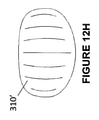
図12Hは、図12Gに示すものと同様のパターンを含むインタフェース対向固定要素310’の例を示す。しかしながら、図示するインタフェース対向固定要素310’では、真ん中のスリットは、直線状であり、インタフェース対向固定要素310’の第2縁306に対して実質的に平行であり、他のスリットは、真ん中のスリットに向かって内向きに湾曲している。
FIG. 12H shows an example of an interface facing fixed element 310'containing a pattern similar to that shown in FIG. 12G. However, in the illustrated interface facing fixing element 310', the middle slit is linear and substantially parallel to the
固定構造体300の図示する実施形態は、患者の顔面における患者インタフェース200の保持に役立つためには有用であるが、場合によっては、固定構造体300に加えられる力により、固定構造体300は患者の顔面から意図せずに持ち上げられることになる可能性があり、それは、患者および/または患者の世話をしている医療専門家に対して不都合である可能性がある。これは、固定構造体300から患者インタフェース200を除去するために加えられる力の一部が固定構造体300に伝達される可能性があるため、発生する可能性がある。たとえば、患者の頬に対して垂直な方向に、力が加えられる可能性がある。患者インタフェース200の除去時等、患者の頬から固定構造体300が意図せずに除去される可能性を低減させるために、患者の頬に対する固定構造体300の接着力は、患者インタフェース200に対する固定構造体300の接着力より大きくすることができる。患者の顔面から固定構造体300を除去するためには、患者の顔面と固定構造体300との間の接着力に打ち勝つ除去力を加えることができる。別法として、水等の除去剤の塗布等、除去機構により、患者の顔面と固定構造体300との間の接着力を低減させることができる。他の除去剤も企図される。
The illustrated embodiment of the fixed
図6Aは、患者対向領域301が患者の顔面に固定されている固定構造体300を示す。言い換えれば、患者対向領域301は、図6Aのページ内に面している。図示するように、固定構造体300の第1縁304は、患者の鼻N、人中Pおよび/または口Mの方に面する。インタフェース対向固定要素310’は、患者インタフェース200の第1本体206Aの取付構造体216Aと結合するかまたはそれに取り付けられるように適合されている。いくつかの構成では、インタフェース対向固定要素310’と適切に位置合せされると、患者インタフェース200の本体206A、206Bおよび/またはブリッジ204は、患者の口Mの上方にかつ人中Pを越えて載ることができる。
FIG. 6A shows a fixed
場合によっては、患者の顔面に固定構造体300を維持しながら、固定構造体300への取付によって患者の顔面に配置されている患者インタフェース200を取り外すことが望ましい可能性がある。たとえば、これは、患者インタフェース200を洗浄しかつ/もしくは交換し、または、限定されないが経鼻胃チューブもしくは経鼻空腸チューブを含むチューブを顔面に固定するとき、望ましい可能性がある。しかしながら、患者の顔面に対する固定構造体300の固定強度が不十分であることにより、固定構造体300の一部が顔面から離れるように持ち上げらやすくなることが分かった。たとえば、インタフェース対向固定要素310’に対して持上げ力(たとえば、固定構造体300に対して実質的に垂直な力)がかけられることに応じて、患者の顔面から離れるように固定構造体300を持ち上げることができる。いくつかの構成では、患者インタフェース200が固定構造体300から除去されている間に、固定構造体300の持上げ力を加えることができる。固定構造体300と患者の顔面との間の固定強度は、たとえば、患者対向領域301の患者対向固定要素310の接着材料または粘着材料の接着力によって決まる可能性がある。場合によっては、患者対向固定要素310の全体、したがって固定構造体300を顔面から取り外すことができる。いくつかの実施形態では、インタフェース対向固定要素310’に持上げ力がかけられると、(図6Bにおいてページ内に面している)患者対向固定要素310に持上げ力を伝達することができる。図6Bに図示するように、この力の伝達により、固定構造体300の第1縁304、または本体302の他の部分を顔面から持ち上げることができる。
In some cases, it may be desirable to remove the
固定構造体300の1つまたは複数の部分の形状は、固定構造体300が、たとえば患者インタフェース200の除去時に、顔面から持ち上げられるのに耐える能力における要素であり得ることが分かった。特に、図5A~図6Bに示す固定構造体300の実施形態では、テーパ状の第1縁304は、固定構造体300にかけられる持上げ力によってもたらされる圧力を集中させて、固定構造体300が顔面から持ち上げられやすくする役割を果たす。実施形態では、固定構造体300の形状は、固定構造体300が顔面から除去される際の圧力分布プロファイルを確定するように選択することができる。
It has been found that the shape of one or more parts of the fixed
図7A~図7Eは、固定構造体300およびインタフェース対向固定要素310’の実施形態の限定しない例を示す。固定構造体300のさまざまな図示する実施形態の本体302は、上記実施形態のうちのいくつかに関連して記載したような、テーパ状となるかまたは幅が狭くなる第1縁ではなく、第1縁304の実質的に平坦なまたは直線状の実施形態を含む。平坦なまたは直線状の第1縁304により、持上げ力によってもたらされる圧力を、第1縁304の長さに沿って分散させることができる。実施形態では、固定構造体300のコーナは実質的に丸い。実施形態では、インタフェース対向固定要素310’のコーナは実質的に丸い。
7A-7E show unrestricted examples of embodiments of the fixed
図7Aは、第2縁306が曲線的である固定構造体300の実施形態例を示す。第3縁308Aおよび第4縁308Bは、少なくとも部分的に曲線的である。インタフェース対向固定要素310’は、第3縁308Aと第4縁308Bとの間に画定された方向において、実質的に本体302のインタフェース対向領域301’の全体に沿って延在する。インタフェース対向固定要素310’は、第1縁304と第2縁306との間に画定された方向において、本体302のインタフェース対向領域301’に部分的に沿って延在する。結果として、第2縁306の一部は、インタフェース対向固定要素310’に隣接しない可能性がある。
FIG. 7A shows an embodiment of the fixed
図7Bは、第2縁306が実質的に平坦であるかまたは直線状である、固定構造体300の実施形態例を示す。第3縁308Aおよび第4縁308Bは実質的に曲線的である。インタフェース対向固定要素310’は、本体302のインタフェース対向領域301’の実質的に全体を覆う。別法として、インタフェース対向固定要素310’は、インタフェース対向領域301’の少なくとも一部を覆うことができる。インタフェース対向領域301’は、インタフェース対向固定要素310’の周囲に境界または縁を提供することができる。使用者(たとえば、看護師または他の医療提供者)は、固定構造体300の縁を把持して、患者の顔面から固定構造体300を除去することができる。固定構造体300のサイズに対するインタフェース対向固定要素310’のサイズは、患者インタフェース200の除去中に固定構造体300に加えられる力によって固定構造体300が患者の顔面から除去されないように、構成することができる。
FIG. 7B shows an embodiment of a fixed
図7Cは、第1縁304、第2縁306、第3縁308Aおよび第4縁308Bがすべて実質的に平坦であるかまたは直線状である、固定構造体300の実施形態例を示す。例として、固定構造体300は、実質的に正方形または実質的に矩形の形状を形成する。代替例では、固定構造体300のコーナは実質的に丸い。インタフェース対向固定要素310’は、本体302のインタフェース対向領域301’の実質的に全体を覆う。別法として、インタフェース対向固定要素310’は、インタフェース対向領域301’の少なくとも一部を覆う。インタフェース対向領域301’は、インタフェース対向固定要素310’の周囲に境界または縁を提供することができる。使用者(たとえば、看護師または他の医療提供者)は、固定構造体300の縁を把持して、患者の顔面から固定構造体300を除去することができる。固定構造体300のサイズに対するインタフェース対向固定要素310’のサイズは、患者インタフェース200の除去中に固定構造体300に加えられる力によって固定構造体300が患者の顔面から除去されないように、構成することができる。
FIG. 7C shows an embodiment of a fixed
図7Dは、第1縁304、第2縁306、第3縁308Aおよび第4縁308Bがすべて実質的に平坦であるかまたは直線状である、固定構造体300の実施形態例を示す。インタフェース対向固定要素310’は、本体302のインタフェース対向領域301’の一部のみを覆う。特に、インタフェース対向固定要素310’は、第1縁304から、第1縁304と第2縁306との間の本体302の長さLに沿った位置まで延在し、第4縁308Bから、第3縁308Aと第4縁308Bとの間の本体302の幅Wに沿った位置まで延在する。図示するように、いくつかの構成では、本体302および/またはインタフェース対向固定要素310’は、概して正方形の周囲形状を有する。いくつかの構成では、インタフェース対向固定要素310’は、対角線Vに沿って延在する平面を中心に実質的に対称であり得る。図示するように、いくつかの構成では、対角線Vは、第1縁304および第4縁308Bによって画定される頂点と、第2縁306および第3縁308Aによって画定される頂点との間に延在する。そして、固定構造体300は、顔面の両頬に配置されるように90度回転可能であり得る。実質的に対称の構造(たとえば、周囲形状)を備えた固定構造体300の実施形態により、利便性を向上させることができ、かつ/または医療機関が購入し、貯蔵し、維持する異なる部品の数を低減させることができる。
FIG. 7D shows an embodiment of a fixed
図7Eは、第1縁304、第2縁306、第3縁308Aおよび第4縁308Bがすべて実質的に平坦であるかまたは直線状である、固定構造体300の実施形態例を示す。インタフェース対向固定要素310’は、第1縁304と第2縁306との間の本体302のインタフェース対向領域301’の長さの全体に沿って実質的に延在する。インタフェース対向固定要素310’は、第4縁308Bから第3縁308Aと第4縁308Bとの間の位置まで本体302のインタフェース対向領域301’の幅に沿って部分的にのみ延在する。
FIG. 7E shows an embodiment of a fixed
図7Fおよび図7Gは、固定構造体300の限定しない構成を示す。図7Fは、縁のすべてが実質的に曲線的である実質的に楕円形状を有する固定構造体300の実施形態を示す。第1縁304は、その長さに沿ってわずかにテーパ状であるが、そのテーパは、図5A~図6Bに示す固定構造体のように延長部またはつまみで終端しない。第1縁304の曲率は、固定構造体300に持ち上げ力が加えられるときに、第1縁304に対して望ましくないように集中する圧力を回避しながら、審美的に美しい形状が与えられるというものである。
7F and 7G show an unlimited configuration of the fixed
図7Gは、実質的に三角形の形状、または曲線的である縁を備えたルーローの三角形状の形状もしくは「ギターピック」状の形状と同様の形状を有する固定構造体300の実施形態を示す。この形状は、実質的に対称であり、鼻の両側に配置されて、回転または再方向付けを必要とすることなく同じ機械的特徴を有することができる。同様に、第1縁304および第2縁306(この場合、いずれも、使用時に患者の鼻および/または口の方に面するように適合されている)は、曲線的であり、わずかにテーパ状であるが、固定構造体300に持上げ力が加えられるとき、第1縁304および第2縁306に対する望ましくないように集中する圧力を依然として回避する。
FIG. 7G shows an embodiment of a fixed
固定構造体300に対する他の有用な形状が企図される。患者によっては、顔のゆがみ(たとえば、号泣または感情の表現による)または固定構造体300の不適切な取扱いにより、固定構造体300が眼またはまぶたの上を移動し、患者に対して瞬間の強圧または刺激をもたらす可能性がある。場合によっては、固定構造体300の本体302に、せん断力、たとえば固定構造体300を眼の方に付勢する力がかけられるとき、患者の眼内に押し込まれる可能性が低いように固定構造体300を形成することが望ましい。
Other useful shapes for the fixed
図13Aは、固定構造体300に対する限定しない構成のインタフェース対向図を示す。固定構造体300の図示する実施形態は、使用時に患者の鼻または口の方に面する第1縁304の実施形態と、使用時に患者の鼻または口から離れる方に面する第2縁306の実施形態とを含む。対向する第3縁308Aおよび第4縁308Bは、第1縁304と第2縁306との間に延在する。図示するように、第3縁308Aおよび第4縁308Bは、(たとえば、固定構造体300の長手方向軸に対して)凹状湾曲部を含むことができる。図示するように、いくつかの実施形態では、第3縁308Aおよび第4縁308Bは、反対方向に湾曲するかまたは面する湾曲部を含む。第3縁308Aおよび第4縁308Bは、第1縁304および第2縁306から遠い第3縁308Aおよび第4縁308Bの部分(たとえば、第3縁308Aおよび第4縁308Bの中心部分)より、第1縁304および第2縁306に近い第3縁308Aおよび第4縁308Bの部分において、本体302の中心線または中心部分からより一層突出している。第2縁306に近い第3縁308Aおよび第4縁308Bの部分は、第1縁304に近い第3縁308Aおよび第4縁308Bの部分より、本体302の中心線または中心部分からより一層突出している。第4縁308Bの凹状湾曲部は、眼、または下まぶた等のまぶたの輪郭に実質的に一致する。力ベクトルF1に沿って示すような上向きの力が、固定構造体300の本体302にかけられると、第4縁308Bの凹状部の曲率は、固定構造体300の本体302が眼の領域の周囲でへこむかまたは移動する傾向を増大させる。これにより、たとえば、本体302は、下まぶたの輪郭をへこませる可能性があり、かつ/または本体302が眼または瞼の中または上に移動する傾向を低減させることができる。第3縁308Aおよび第4縁308Bの両方に凹状湾曲部が存在するため、固定構造体300は、同じ特性を維持しながら、顔のいずれの側でも使用されるようにおよそ180度回転することができる。
FIG. 13A shows an interface facing diagram having an unlimited configuration with respect to the fixed
図示するように、インタフェース対向固定要素310’は、固定構造体300のインタフェース対向領域301’にあり、したがって、患者の顔面から離れる方に面する。インタフェース対向固定要素310’は、本体302の中心部分からずれている。図示する構成では、インタフェース対向固定要素310’は、第2縁306より第1縁304に近いように位置決めされている。さらに、インタフェース対向固定要素310’の長さL1は、固定構造体300の本体302の長さL2より小さいかまたはそれに等しく、L2は、第1縁304と第2縁306との間の長さとして定義される。いくつかの構成では、長さの比L1:L2は、0.2~0.9の範囲、または0.3~0.8の範囲、または0.4~0.7の範囲、または0.5~0.6の範囲にあり得る。インタフェース対向固定要素310’が本体302の中心部分からずれており、長さL1およびL2がこうした比を有する場合、本体302のインタフェース対向固定要素310’から最も遠い部分、たとえば、本体302の第2縁306により近い部分は、固定構造体300を患者の顔面に取り付けるかまたはそこから取り外すとき、より優れた把持領域を提供することができる。
As shown, the interface facing fixation element 310'is in the interface facing region 301' of the fixed
いくつかの実施形態では、固定構造体300は、支持部分として作用することができる拡大した領域を有する。たとえば、固定構造体300は、第1縁304、第2縁306、第3縁308Aおよび/または第4縁308B等、タブまたは他の突起を含むことができる。支持部分により、使用者(たとえば、看護師)は、指または器具を用いて支持部分を作動させる(たとえば、押し下げる)ことができる。これは、管(たとえば、経鼻胃チューブまたは経鼻空腸チューブ)および/または患者インタフェースから固定構造体300を分離するのに役立つことができる。いくつかの変形では、支持部分は、患者から管を除去するのに役立つことができる。いくつかの実施形態では、支持部分は、固定構造体300を安定化させるのに役立つことができ、かつ/または患者の顔面における固定構造体300の分断を低減させることができる。
In some embodiments, the fixed
図13Aに示す固定構造体300の変形が企図されることが理解されるべきである。たとえば、いくつかの構成では、使用時に、患者の眼またはまぶたの方に面する縁等、第3縁308Aまたは第4縁308Bのうちの一方のみに、凹状湾曲部が存在する場合がある。いくつかの構成では、凹状湾曲部がある代わりに、第3縁308Aまたは第4縁308Bのうちの一方は、第1縁304および第2縁306のうちの一方に近い第3縁308Aまたは第4縁308Bの部分においてのみ、固定構造体300の中心線または中心部分からさらに延在することができる。いくつかの構成では、第2縁306に近い第3縁308Aおよび第4縁308Bの部分は、第1縁304に近い第3縁308Aおよび第4縁308Bの部分より、本体302の中心線または中心部分から短い距離、またはおよそそれに等しい距離、突出することができる。いくつかの構成では、凹状湾曲部は、限定されないが三日月形状を含むより誇張した形状を有することができる。いくつかの構成では、インタフェース対向固定要素310’は、固定構造体300の中心からずれているのではなく固定構造体300の中心またはその近くに存在することができる。いくつかの構成では、インタフェース対向固定要素310’は、固定構造体300のインタフェース対向領域301’の大部分または実質的に全体を占有することができる。
It should be understood that the modification of the fixed
図13Bは、断面C-Cに沿った図13Aの固定構造体300の図を示す。図示するように、固定構造体300の本体302は厚さt1を有し、インタフェース対向固定要素310’は厚さt2を有する。本体302に対して、たとえば号泣または感情の表現による顔面の形状の変化に沿うことができるように、高い可撓性または低いヤング率が望ましいことが理解されている。本体302の厚さt1は、たとえば、0.05mm~0.35mm、または0.10mm~0.30mm、または0.15mm~0.25mmの範囲であり得る。いくつかの実施形態では、本体302の厚さt1は、たとえば、0.05mm~5.0mm±10%、0.05mm~3.0mm±10%、0.1mm~1.0mm±10%、0.178mm~0.76mm±10%、0.178mm~0.381mm±10%、0.38mm~0.76mm±10%の範囲、またはおよそ0.76mm±10%であり得る。いくつかの実施形態では、本体302の厚さt1は、0.178mmに等しいかまたはおよそ0.178mmである。いくつかの実施形態では、本体302の厚さt1は、インタフェース対向固定要素310’の厚さt2に等しいか、およそ等しいか、またはそれより小さい可能性がある。相対的に小さい厚さt1を有する本体302は、固定構造体300の全体的な可撓性を増大させることができる。いくつかの実施形態では、本体302は、ヤング率の低い材料を含む。いくつかの変形では、本体302の全体または本体302の実質的に全体は、ヤング率の低い材料を含む。いくつかの構成では、本体302の可撓性を増大させることにより、本体302の患者対向領域301は、患者の顔面に強力には接着しない可能性がある。別法として、本体302の患者対向領域301と患者の顔面との間の接着力を増大させることにより、本体302の可撓性が低減する可能性がある。したがって、可撓性を維持しながら、本体302の患者対向領域301と患者の顔面との間の接着力を最適化することが望ましい。異なる材料は、本体302の可撓性および/または接着力に対して異なる影響を与える可能性がある。
FIG. 13B shows a diagram of the fixed
図14および図15は、固定構造体300に対するさらなる限定しない実施形態のインタフェース対向図を示す。図14および図15の実施形態は、図13Aの実施形態の特徴のうちの任意のものを含むことができる。たとえば、図示するように、図14および図15の実施形態は、本体302、第1縁304および第2縁306を含むことができる。第1縁304は、使用時に、患者の鼻または口の方に面することができ、第2縁306は、使用時に、患者の鼻または口から離れる方に面することができる。対向する第3縁308Aおよび第4縁308Bは、第1縁304と第2縁306との間に延在することができる。図示するように、第3縁308Aおよび第4縁308Bは、(たとえば、固定構造体300の長手方向軸に対して)凹状湾曲部を含むことができる。
14 and 15 show interface facing views of a further unlimited embodiment for the fixed
固定構造体300は、インタフェース対向固定要素310’を含むことができる。インタフェース対向固定要素310’は、固定構造体300のインタフェース対向領域301’にあり、したがって、患者の顔面から離れる方に面する。インタフェース対向固定要素310’は、本体302の中心部分からずれている可能性がある。図示する構成では、インタフェース対向固定要素310’は、第2縁306より第1縁304に近いように位置決めされている。
The fixed
インタフェース対向固定要素310’は、1つまたは複数のスリットを含むことができる。スリットは、スリットの形状の交互の列を含むパターンであり得る。たとえば、図示するように、各列は、両側の列に対して反対の方向に面し、かつ両側の列から少なくとも部分的にずれている形状を備えた、弓形および/または半円形スリットを含むことができる。いくつかの実施形態では、スリットの列の一部は、固定構造体300の長手方向において部分的に重なっている。
The interface facing fixed element 310'can include one or more slits. The slits can be a pattern containing alternating rows of slit shapes. For example, as illustrated, each row includes a bow and / or semi-circular slit with a shape that faces opposite to the rows on either side and is at least partially offset from the rows on both sides. be able to. In some embodiments, some of the rows of slits partially overlap in the longitudinal direction of the fixed
場合によっては、使用時、固定構造体300の周囲に、涙、粘液、吐物もしくは他の液体または液体固体混合物が存在する可能性がある。こうした物質の存在により、患者に対する固定構造体300の患者対向領域301の接着力が低減する可能性がある。液体または液体固体混合物の存在による患者対向領域301の顔面に対する接着力の喪失を低減させるように、固定構造体300の本体302を、比較的低い吸湿性を有する材料から構成することが望ましいことが理解されている。
In some cases, tears, mucus, vomitus or other liquids or liquid solid mixtures may be present around the fixed
図8Aは、インタフェース対向固定要素310’を含む固定構造体300に対する例示的な限定しない構成を示す。インタフェース対向固定要素310’は、患者インタフェース200の取付構造体216A、216Bのうちの一方との「フック・ループ」型接続を形成するフック状パッドを含む。フック状パッドはフック314を含む。図8Bは、第1縁304から見て点線A-Aに沿った拡大断面を示す。図示するように、フック314は、固定構造体300の本体302の第4縁308Bに向かって延在している。いくつかの構成では、フック314は、さらにまたは別法として、固定構造体300の本体302の第3縁308Aに向かって延在している。場合によっては、固定構造体300が、幼児または新生児等の患者の顔面で使用される場合、患者を傾けて、第1縁304または第2縁306のいずれかを把持し、固定構造体300の長さを横切ってそれぞれの縁を引っ張ることにより、固定構造体300を除去するように試みられる。フック・ループ固定の強度は、フック314の向きに対して異方性であることが理解されている。
FIG. 8A shows an exemplary, unrestricted configuration for a fixed
いくつかの構成では、図9Aおよび図9Bに示すように、フック314は、第2縁306に向かって延在するように配置することができる。(図9Bは、第3縁308Aから見て線B-Bに沿った図9Aの断面である。)他の構成では、フック314は、第1縁304、第2縁306、または第1縁304および第2縁306に向かって延在するように配置することができる。フック314が、第1縁304および/または第2縁306に向かって延在するように配置されている場合、フック・ループ固定の強度は、第1縁304および/または第2縁306に対して実質的に平行な軸に沿って力が加えられる場合より、第3縁308Aおよび/または第4縁308Bに対して実質的に平行な軸に沿って力が加えられる場合の方が、分離がより強く抵抗されるようなものであり得る。フック314に対して相補的なループが、こうした力が加えられるときに、フック314に対して実質的に垂直な方向に付勢されるのではなく、フック314の長さに向かってかつ/またはそれに対して実質的に付勢されるため、力はより強く抵抗される。いくつかの構成では、フック314は、複数の方向に延在することができる。いくつかのこうした構成では、フック314は、フック・ループ固定の強度の異方性を緩和するように、たとえば実質的に垂直な方向に延在することができる。いくつかの構成では、フック314の角度は、異なる用途に適合するように変更することができる。いくつかの構成では、異なる角度の組合せを用いて、インタフェース対向固定要素310’と患者インタフェース200との間の固定の強度を確定することができる。固定強度を補助するために、複数の異なる角度および/または異なる方向にフック314を位置決めすることができる。
In some configurations, the
実施形態では、図5Cおよび図11A~図12Hに示すスリットの実施形態のうちの少なくとも1つとフック314の構成との組合せを用いて、患者インタフェース200とのインタフェース対向固定要素310’の固定強度および/または可撓性を最大限にすることができる。
In embodiments, the combination of at least one of the slit embodiments shown in FIGS. 5C and 11A-12H with the configuration of
図10Aは、患者の顔面の皮膚表面Sにおける固定構造体300の使用を示す。患者対向領域301は、皮膚表面Sに接着する材料、たとえば、親水コロイド系接着剤から構成することができる、患者対向固定要素310を含む。図示するように、顕微鏡レベルでは、皮膚表面Sは、皮膚表面Sに沿った不規則な厚さを含み、複数の出っ張りおよび間隙Gを含む。患者対向固定要素310は、皮膚表面Sに適用されると、最初は、皮膚表面Sの一部にのみ接着する(図10Aの左側の図面を参照)。期間tの間に、接着性の患者対向固定要素310は、間隙Gに流れ込み、接着力を増大させる(図10Aの右側の図面を参照)。しかしながら、固定構造体300が皮膚表面Sから除去されるときに不快感があり、それは、場合によっては、皮膚表面Sの体毛および角質層の一部が同時に除去されるためである、ということが理解されている。さらに、場合によっては、皮膚表面Sに接着剤を塗布した後、折々の接着剤の強度を予測することは困難である。
FIG. 10A shows the use of the fixed
図10Bは、固定構造体300の実施形態の使用を示し、そこでは、患者対向固定要素310は、シリコーン系接着剤から構成されている。図示するように、顕微鏡レベルで、皮膚表面への適用時、患者対向固定要素310は、迅速に間隙Gに流れ込み、急速に皮膚に対する最大接着力に達する。したがって、接着剤の塗布後の折々の接着剤の強度は、より予測可能になる。シリコーン系接着剤は、親水コロイド系接着剤より接着力が低く、親水コロイド系接着剤より除去するために必要な力が小さい。接着剤と皮膚との間の接触面積を増大させることにより、それらの間の十分な接着力を可能にし、固定構造体300が除去されるときの皮膚表面の一部の除去を低減させることができる。患者対向固定要素310がシリコーン系接着剤から構成されている場合、皮膚からの固定構造体300の除去または取外しの不快感を低減させることができる。
FIG. 10B illustrates the use of an embodiment of the
別段文脈から明らかに必要でない限り、明細書および特許請求の範囲を通して、「備える」、「備えている」等の用語は、排他的または網羅的な意味とは対照的に包括的な意味で、すなわち、「含むが限定されない」という意味で解釈されるべきである。 Unless expressly necessary from the context, the terms "prepared", "prepared", etc., throughout the specification and claims, have a comprehensive meaning as opposed to an exclusive or exhaustive meaning. That is, it should be interpreted in the sense of "including but not limited".
上述した説明において、既知の均等物を有する完全体または構成要素について言及しているが、それらの完全体または構成要素は、個々に示されているかのように本明細書に組み込まれる。 Although the description described above refers to a complete body or component having known equivalents, those complete bodies or components are incorporated herein as if they were individually shown.
開示した方法、装置およびシステムはまた、本開示において個別にまたはまとめて言及されるかまたは示される部品、要素および特徴を、前記部品、要素または特徴のうちの2つ以上の任意のまたはすべての組合せで含むようにも広義に言うことができる。さらに、本開示は、さまざまな実施形態のさまざまな特徴、態様、方法、特性、特質、品質、属性、要素等の組合せを含む。たとえば、本明細書におけるある実施形態に関連する任意の特定の特徴、態様、方法、特性、特質、品質、属性、要素等は、本明細書における他の任意の実施形態に関連して使用することができる。 The disclosed methods, devices and systems also include parts, elements and features individually or collectively referred to or indicated in the present disclosure, in any or all of the two or more of the parts, elements or features. It can be broadly said to include it in combination. Further, the present disclosure includes combinations of different features, embodiments, methods, characteristics, properties, qualities, attributes, elements, etc. of different embodiments. For example, any particular feature, aspect, method, characteristic, characteristic, quality, attribute, element, etc. associated with an embodiment herein may be used in connection with any other embodiment herein. be able to.
本明細書におけるいかなる先行技術に対する言及も、その先行技術が、世界中のいかなる国においても努力傾注分野において共通の一般知識の一部を形成するという承認またはいかなる形態の示唆でもなく、そのように解釈されるべきではない。 No reference to any prior art herein is an endorsement or any form of suggestion that the prior art forms part of common general knowledge in the field of effort focus in any country in the world. Should not be interpreted.
本明細書で用いるような「およそ」、「約」、「概して」および「実質的に」という用語等、本明細書で用いる程度の文言は、依然として所望の機能を実行するかまたは所望の結果を達成する、述べられている値、量または特徴に近い値、量または特徴を表す。述べられている値、量または特徴からのずれは、たとえば、「概して平行な」および「実質的に平行な」という用語は、15度、10度、5度、3度、1度、0.1度等以下、厳密に平行であることから逸脱することができる値、量または特徴を指す。 The degree of wording used herein, such as the terms "approximately," "about," "generally," and "substantially," as used herein, still performs the desired function or results. Represents a value, quantity or feature close to the stated value, quantity or feature to achieve. Deviations from the stated values, quantities or features are, for example, the terms "generally parallel" and "substantially parallel" are 15 degrees, 10 degrees, 5 degrees, 3 degrees, 1 degree, 0. It refers to a value, quantity, or feature that can deviate from being strictly parallel, such as 1 degree or less.
いくつかの実施形態について、添付図面に関連して記載した。図は、正確な尺度で描かれていないが、こうした尺度は限定するものであるべきではない。図示されているもの以外の寸法および比が企図され、本開示の範囲内にある。距離、角度、形状等は、単に例示的なものであり、必ずしも、図示する装置の実際の寸法および配置に厳密に関連するとは限らない。構成要素を追加し、除去し、かつ/または再配置することができる。 Some embodiments have been described in connection with the accompanying drawings. The figures are not drawn on an accurate scale, but these scales should not be limiting. Dimensions and ratios other than those shown are contemplated and are within the scope of this disclosure. Distances, angles, shapes, etc. are merely exemplary and may not necessarily be strictly related to the actual dimensions and arrangement of the illustrated device. Components can be added, removed, and / or rearranged.
いくつかの実施形態に関して本開示について記載したが、当業者には明らかである他の実施形態もまた、本開示の範囲内にある。したがって、本開示の趣旨および範囲から逸脱することなく、さまざまな変形および変更を行うことができる。たとえば、要求に応じてさまざまな構成要素を再配置することができる。さらに、本開示を実施するために、特徴、態様および利点の必ずしもすべてが必要であるとは限らない。したがって、本開示の範囲は、以下の特許請求の範囲によってのみ定義されるように意図されている。 Although this disclosure has been described for some embodiments, other embodiments apparent to those of skill in the art are also within the scope of this disclosure. Therefore, various modifications and changes can be made without departing from the spirit and scope of this disclosure. For example, various components can be rearranged on demand. Moreover, not all features, embodiments and advantages are required to carry out the present disclosure. Therefore, the scope of the present disclosure is intended to be defined only by the following claims.
Claims (16)
第1縁と、
前記患者の顔面での使用時、前記第1縁より前記患者の鼻または口から遠いように、前記第1縁に対向する第2縁と、
前記第1縁と前記第2縁との間に延在する、対向する第3縁および第4縁と、
を備え、
前記第1縁および前記第2縁に近い方の前記第3縁の部分が、前記第1縁および前記第2縁から遠い方の前記第3縁の部分より、前記固定構造体の中心線または中心部分からより一層突出し、
前記第2縁に近い方の前記第3縁の部分が、前記第1縁に近い方の前記第3縁の部分より、前記固定構造体の前記中心線または中心部分からより一層突出し、
前記中心線または中心部分は、前記第3縁と前記第4縁との間の中途であり、前記第3縁と前記第4縁とは、前記中心線または中心部分を中心に、お互いに対して対称であり、
前記第3縁及び前記第4縁が凹状湾曲部を備え、
前記第4縁が、前記患者の目の下の領域の形状に一致するような形状である凹状湾曲部を備える、固定構造体。 A fixed structure that secures the patient interface to the patient's face.
The first edge and
When used on the patient's face, the second edge facing the first edge and the second edge facing the first edge so as to be farther from the patient's nose or mouth than the first edge.
Opposing third and fourth edges extending between the first edge and the second edge,
Equipped with
The portion of the first edge and the third edge closer to the second edge is the centerline of the fixed structure or the portion of the third edge farther from the first edge and the second edge. Even more protruding from the central part,
The portion of the third edge closer to the second edge protrudes further from the center line or the central portion of the fixed structure than the portion of the third edge closer to the first edge.
The center line or the central portion is in the middle between the third edge and the fourth edge, and the third edge and the fourth edge are centered on the center line or the central portion with respect to each other. Symmetrical
The third edge and the fourth edge have a concave curved portion, and the third edge and the fourth edge are provided with a concave curved portion.
A fixed structure comprising a concave curved portion whose fourth edge is shaped to match the shape of the area under the patient's eyes.
前記第1締結具の中間点が、前記第1縁と前記第2縁との間の中途の中心線または中心部分からずれており、前記第1締結具は前記第2縁に対してよりも前記第1縁に対してより近くに位置し、
前記第1締結具の中間点が、前記第3縁と前記第4縁との間の中途の中心線または中心部分にある、請求項1に記載の固定構造体。 It comprises a first surface extending between the first edge and the second edge, the first surface facing away from the patient's face and towards the patient interface during use. One side comprises a first fastener that can be attached to a complementary fastener of the patient interface attachment structure.
The midpoint of the first fastener is offset from the midline or central portion between the first edge and the second edge, and the first fastener is more than relative to the second edge. Located closer to the first edge,
The fixed structure according to claim 1, wherein the intermediate point of the first fastener is in the center line or the central portion in the middle between the third edge and the fourth edge.
前記第1面の長さに対する前記第1締結具の長さの比が、0.2~0.9である、請求項2に記載の固定構造体。 The length of the first fastener between the first edge and the second edge is shorter than the length of the first surface between the first edge and the second edge.
The fixed structure according to claim 2, wherein the ratio of the length of the first fastener to the length of the first surface is 0.2 to 0.9.
前記第1縁および前記第2縁に近い方の前記複数のスリットのうちの少なくともいくつかが、前記第1縁および前記第2縁から遠い方の前記複数のスリットのうちの少なくともいくつかより短い、請求項5に記載の固定構造体。 At least some of the plurality of slits extend towards the third and fourth edges.
At least some of the first edge and the plurality of slits closer to the second edge are shorter than at least some of the first edge and the plurality of slits farther from the second edge. , The fixed structure according to claim 5.
前記第2締結具が、前記患者の顔面に取外し可能に取付け可能な接着剤を備える、請求項2~9のいずれか一項に記載の固定構造体。 It comprises a second surface extending between the first edge and the second edge, the second surface facing the patient's face and away from the patient interface during use. Two sides are provided with a second fastener that can be attached to the patient's face.
The fixed structure according to any one of claims 2 to 9, wherein the second fastener comprises an adhesive that is removable and attachable to the patient's face.
前記固定構造体が、0.05mm~5mmの厚さを有する、請求項1~14のいずれか一項に記載の固定構造体。 The fixed structure has a thickness that allows the fixed structure to bend in response to the movement of the patient's face.
The fixed structure according to any one of claims 1 to 14, wherein the fixed structure has a thickness of 0.05 mm to 5 mm.
Applications Claiming Priority (7)
| Application Number | Priority Date | Filing Date | Title |
|---|---|---|---|
| US201562133908P | 2015-03-16 | 2015-03-16 | |
| US62/133,908 | 2015-03-16 | ||
| US201562151898P | 2015-04-23 | 2015-04-23 | |
| US62/151,898 | 2015-04-23 | ||
| US201562252943P | 2015-11-09 | 2015-11-09 | |
| US62/252,943 | 2015-11-09 | ||
| PCT/NZ2016/050041 WO2016148585A1 (en) | 2015-03-16 | 2016-03-16 | Patient interface |
Related Child Applications (1)
| Application Number | Title | Priority Date | Filing Date |
|---|---|---|---|
| JP2021017579A Division JP7234273B2 (en) | 2015-03-16 | 2021-02-05 | patient interface |
Publications (3)
| Publication Number | Publication Date |
|---|---|
| JP2018512205A JP2018512205A (en) | 2018-05-17 |
| JP2018512205A5 JP2018512205A5 (en) | 2019-04-25 |
| JP6999420B2 true JP6999420B2 (en) | 2022-01-18 |
Family
ID=56919174
Family Applications (3)
| Application Number | Title | Priority Date | Filing Date |
|---|---|---|---|
| JP2017548860A Active JP6999420B2 (en) | 2015-03-16 | 2016-03-16 | Patient interface |
| JP2021017579A Active JP7234273B2 (en) | 2015-03-16 | 2021-02-05 | patient interface |
| JP2022163554A Pending JP2022190185A (en) | 2015-03-16 | 2022-10-11 | patient interface |
Family Applications After (2)
| Application Number | Title | Priority Date | Filing Date |
|---|---|---|---|
| JP2021017579A Active JP7234273B2 (en) | 2015-03-16 | 2021-02-05 | patient interface |
| JP2022163554A Pending JP2022190185A (en) | 2015-03-16 | 2022-10-11 | patient interface |
Country Status (6)
| Country | Link |
|---|---|
| US (1) | US20180043124A1 (en) |
| EP (2) | EP3906957A1 (en) |
| JP (3) | JP6999420B2 (en) |
| CN (3) | CN107427661B (en) |
| AU (3) | AU2016233997B2 (en) |
| WO (1) | WO2016148585A1 (en) |
Families Citing this family (6)
| Publication number | Priority date | Publication date | Assignee | Title |
|---|---|---|---|---|
| CN109906097B (en) | 2016-08-31 | 2022-01-14 | 费雪派克医疗保健有限公司 | Patient interface, system and method |
| USD849243S1 (en) * | 2017-11-21 | 2019-05-21 | Fisher & Paykel Healthcare Limited | Nasal cannula |
| USD849242S1 (en) * | 2017-11-21 | 2019-05-21 | Fisher & Paykel Healthcare Limited | Nasal cannula assembly |
| US20210379311A1 (en) * | 2020-06-08 | 2021-12-09 | Koninklijke Philips N.V. | Sealing arrangement for forming a seal between a patient and a patient interface device |
| AU2021323938A1 (en) * | 2020-08-11 | 2023-04-20 | EzyAid Pty Ltd | Apparatus for holding a tube and associated method of use |
| KR102545210B1 (en) * | 2020-12-10 | 2023-06-20 | 신진숙 | adhesion-type positive airway pressure mask |
Citations (3)
| Publication number | Priority date | Publication date | Assignee | Title |
|---|---|---|---|---|
| JP2013540037A (en) | 2010-10-18 | 2013-10-31 | フィッシャー アンド ペイケル ヘルスケア リミテッド | Nasal cannula, conduit and fixation system |
| WO2014142681A1 (en) | 2013-03-15 | 2014-09-18 | Fisher & Paykel Healthcare Limited | Nasal cannula assemblies and related parts |
| JP2014213123A (en) | 2013-04-30 | 2014-11-17 | 株式会社 メディカル プロジェクト | Fixing implement for medical tube |
Family Cites Families (11)
| Publication number | Priority date | Publication date | Assignee | Title |
|---|---|---|---|---|
| US5143061A (en) * | 1990-08-17 | 1992-09-01 | Kaimer Stephen F | Supplemental seal for oxygen mask |
| US5271745A (en) * | 1992-10-27 | 1993-12-21 | Tabex Industries, Inc. | Medical tubing retaining device and method of use |
| US6050263A (en) * | 1998-06-22 | 2000-04-18 | Neotech Products, Inc. | Endotracheal tube holder |
| US7856982B2 (en) * | 2004-03-11 | 2010-12-28 | Ric Investments, Llc | Patient interface device |
| US7624735B2 (en) * | 2004-09-21 | 2009-12-01 | Respironics Respiratory Drug Delivery (Uk) Ltd | Cheek-mounted patient interface |
| US8161971B2 (en) * | 2006-08-04 | 2012-04-24 | Ric Investments, Llc | Nasal and oral patient interface |
| BRPI0820581A8 (en) * | 2007-11-19 | 2015-11-10 | Koninl Philips Electronics Nv | PATIENT INTERFACE DEVICE, AND, NASAL CANNULA |
| CN105126222A (en) * | 2008-06-04 | 2015-12-09 | 瑞思迈有限公司 | Patient interface system |
| US20110315148A1 (en) * | 2010-06-12 | 2011-12-29 | Widgerow Alan D | Skin adherent medical devices |
| WO2012104756A1 (en) * | 2011-02-03 | 2012-08-09 | Koninklijke Philips Electronics N.V. | Patient interface device having selectively positionable multi-band headgear |
| US9925348B2 (en) * | 2013-07-17 | 2018-03-27 | Upods, Llc | Gas delivery device |
-
2016
- 2016-03-16 US US15/556,770 patent/US20180043124A1/en active Pending
- 2016-03-16 CN CN201680016278.5A patent/CN107427661B/en active Active
- 2016-03-16 EP EP21170149.5A patent/EP3906957A1/en active Pending
- 2016-03-16 AU AU2016233997A patent/AU2016233997B2/en active Active
- 2016-03-16 CN CN202110531920.6A patent/CN113398405A/en active Pending
- 2016-03-16 EP EP16765326.0A patent/EP3270995B1/en active Active
- 2016-03-16 CN CN202110531849.1A patent/CN113274609A/en active Pending
- 2016-03-16 WO PCT/NZ2016/050041 patent/WO2016148585A1/en active Application Filing
- 2016-03-16 JP JP2017548860A patent/JP6999420B2/en active Active
-
2021
- 2021-02-01 AU AU2021200628A patent/AU2021200628A1/en not_active Abandoned
- 2021-02-05 JP JP2021017579A patent/JP7234273B2/en active Active
-
2022
- 2022-10-11 JP JP2022163554A patent/JP2022190185A/en active Pending
-
2023
- 2023-02-22 AU AU2023201038A patent/AU2023201038A1/en active Pending
Patent Citations (3)
| Publication number | Priority date | Publication date | Assignee | Title |
|---|---|---|---|---|
| JP2013540037A (en) | 2010-10-18 | 2013-10-31 | フィッシャー アンド ペイケル ヘルスケア リミテッド | Nasal cannula, conduit and fixation system |
| WO2014142681A1 (en) | 2013-03-15 | 2014-09-18 | Fisher & Paykel Healthcare Limited | Nasal cannula assemblies and related parts |
| JP2014213123A (en) | 2013-04-30 | 2014-11-17 | 株式会社 メディカル プロジェクト | Fixing implement for medical tube |
Also Published As
| Publication number | Publication date |
|---|---|
| AU2023201038A1 (en) | 2023-04-06 |
| EP3270995B1 (en) | 2021-06-23 |
| AU2021200628A1 (en) | 2021-03-11 |
| JP2018512205A (en) | 2018-05-17 |
| WO2016148585A1 (en) | 2016-09-22 |
| CN107427661B (en) | 2021-06-04 |
| JP2021090783A (en) | 2021-06-17 |
| EP3270995A1 (en) | 2018-01-24 |
| CN113398405A (en) | 2021-09-17 |
| JP2022190185A (en) | 2022-12-23 |
| AU2016233997B2 (en) | 2020-11-05 |
| CN107427661A (en) | 2017-12-01 |
| JP7234273B2 (en) | 2023-03-07 |
| EP3906957A1 (en) | 2021-11-10 |
| US20180043124A1 (en) | 2018-02-15 |
| CN113274609A (en) | 2021-08-20 |
| AU2016233997A1 (en) | 2017-09-07 |
| EP3270995A4 (en) | 2018-10-31 |
Similar Documents
| Publication | Publication Date | Title |
|---|---|---|
| JP6999420B2 (en) | Patient interface | |
| US20220040432A1 (en) | Patient interface | |
| JP7346619B2 (en) | Headgear for patient interface | |
| US20050121037A1 (en) | Nasal ventilation interface | |
| CN114423480A (en) | Patient interface | |
| WO2019199180A1 (en) | Headgear for use with a patient interface of a respiratory therapy system |
Legal Events
| Date | Code | Title | Description |
|---|---|---|---|
| A521 | Request for written amendment filed |
Free format text: JAPANESE INTERMEDIATE CODE: A523 Effective date: 20190314 |
|
| A621 | Written request for application examination |
Free format text: JAPANESE INTERMEDIATE CODE: A621 Effective date: 20190314 |
|
| A977 | Report on retrieval |
Free format text: JAPANESE INTERMEDIATE CODE: A971007 Effective date: 20200128 |
|
| A131 | Notification of reasons for refusal |
Free format text: JAPANESE INTERMEDIATE CODE: A131 Effective date: 20200131 |
|
| A601 | Written request for extension of time |
Free format text: JAPANESE INTERMEDIATE CODE: A601 Effective date: 20200430 |
|
| A521 | Request for written amendment filed |
Free format text: JAPANESE INTERMEDIATE CODE: A523 Effective date: 20200727 |
|
| A02 | Decision of refusal |
Free format text: JAPANESE INTERMEDIATE CODE: A02 Effective date: 20201009 |
|
| A521 | Request for written amendment filed |
Free format text: JAPANESE INTERMEDIATE CODE: A523 Effective date: 20210205 |
|
| C60 | Trial request (containing other claim documents, opposition documents) |
Free format text: JAPANESE INTERMEDIATE CODE: C60 Effective date: 20210205 |
|
| C11 | Written invitation by the commissioner to file amendments |
Free format text: JAPANESE INTERMEDIATE CODE: C11 Effective date: 20210219 |
|
| A911 | Transfer to examiner for re-examination before appeal (zenchi) |
Free format text: JAPANESE INTERMEDIATE CODE: A911 Effective date: 20210405 |
|
| C21 | Notice of transfer of a case for reconsideration by examiners before appeal proceedings |
Free format text: JAPANESE INTERMEDIATE CODE: C21 Effective date: 20210406 |
|
| A912 | Re-examination (zenchi) completed and case transferred to appeal board |
Free format text: JAPANESE INTERMEDIATE CODE: A912 Effective date: 20210514 |
|
| C211 | Notice of termination of reconsideration by examiners before appeal proceedings |
Free format text: JAPANESE INTERMEDIATE CODE: C211 Effective date: 20210518 |
|
| C22 | Notice of designation (change) of administrative judge |
Free format text: JAPANESE INTERMEDIATE CODE: C22 Effective date: 20210806 |
|
| C23 | Notice of termination of proceedings |
Free format text: JAPANESE INTERMEDIATE CODE: C23 Effective date: 20211029 |
|
| C03 | Trial/appeal decision taken |
Free format text: JAPANESE INTERMEDIATE CODE: C03 Effective date: 20211126 |
|
| C30A | Notification sent |
Free format text: JAPANESE INTERMEDIATE CODE: C3012 Effective date: 20211126 |
|
| A61 | First payment of annual fees (during grant procedure) |
Free format text: JAPANESE INTERMEDIATE CODE: A61 Effective date: 20211222 |
|
| R150 | Certificate of patent or registration of utility model |
Ref document number: 6999420 Country of ref document: JP Free format text: JAPANESE INTERMEDIATE CODE: R150 |