JP6997188B2 - Fluid delivery device and its assembly method - Google Patents

Fluid delivery device and its assembly method Download PDF

Info

Publication number
JP6997188B2
JP6997188B2 JP2019531372A JP2019531372A JP6997188B2 JP 6997188 B2 JP6997188 B2 JP 6997188B2 JP 2019531372 A JP2019531372 A JP 2019531372A JP 2019531372 A JP2019531372 A JP 2019531372A JP 6997188 B2 JP6997188 B2 JP 6997188B2
Authority
JP
Japan
Prior art keywords
assembly
collet
delivery device
wall portion
fluid delivery
Prior art date
Legal status (The legal status is an assumption and is not a legal conclusion. Google has not performed a legal analysis and makes no representation as to the accuracy of the status listed.)
Active
Application number
JP2019531372A
Other languages
Japanese (ja)
Other versions
JP2020511182A (en
Inventor
ロス、ラッセル・エフ
ベイカー、アンドリュー・ティー
ギャズビー、エリザベス・ディー
ヘイガン、ルーク
ペック、アーロン
ヤマダ、アリソン
ギャナパシー、プラタプ
Current Assignee (The listed assignees may be inaccurate. Google has not performed a legal analysis and makes no representation or warranty as to the accuracy of the list.)
Sorrento Therapeutics Inc
Original Assignee
Sorrento Therapeutics Inc
Priority date (The priority date is an assumption and is not a legal conclusion. Google has not performed a legal analysis and makes no representation as to the accuracy of the date listed.)
Filing date
Publication date
Application filed by Sorrento Therapeutics Inc filed Critical Sorrento Therapeutics Inc
Publication of JP2020511182A publication Critical patent/JP2020511182A/en
Application granted granted Critical
Publication of JP6997188B2 publication Critical patent/JP6997188B2/en
Active legal-status Critical Current
Anticipated expiration legal-status Critical

Links

Images

Classifications

    • AHUMAN NECESSITIES
    • A61MEDICAL OR VETERINARY SCIENCE; HYGIENE
    • A61MDEVICES FOR INTRODUCING MEDIA INTO, OR ONTO, THE BODY; DEVICES FOR TRANSDUCING BODY MEDIA OR FOR TAKING MEDIA FROM THE BODY; DEVICES FOR PRODUCING OR ENDING SLEEP OR STUPOR
    • A61M37/00Other apparatus for introducing media into the body; Percutany, i.e. introducing medicines into the body by diffusion through the skin
    • A61M37/0015Other apparatus for introducing media into the body; Percutany, i.e. introducing medicines into the body by diffusion through the skin by using microneedles
    • AHUMAN NECESSITIES
    • A61MEDICAL OR VETERINARY SCIENCE; HYGIENE
    • A61KPREPARATIONS FOR MEDICAL, DENTAL OR TOILETRY PURPOSES
    • A61K9/00Medicinal preparations characterised by special physical form
    • A61K9/0012Galenical forms characterised by the site of application
    • A61K9/0019Injectable compositions; Intramuscular, intravenous, arterial, subcutaneous administration; Compositions to be administered through the skin in an invasive manner
    • A61K9/0021Intradermal administration, e.g. through microneedle arrays, needleless injectors
    • AHUMAN NECESSITIES
    • A61MEDICAL OR VETERINARY SCIENCE; HYGIENE
    • A61MDEVICES FOR INTRODUCING MEDIA INTO, OR ONTO, THE BODY; DEVICES FOR TRANSDUCING BODY MEDIA OR FOR TAKING MEDIA FROM THE BODY; DEVICES FOR PRODUCING OR ENDING SLEEP OR STUPOR
    • A61M5/00Devices for bringing media into the body in a subcutaneous, intra-vascular or intramuscular way; Accessories therefor, e.g. filling or cleaning devices, arm-rests
    • A61M5/178Syringes
    • A61M5/31Details
    • A61M5/32Needles; Details of needles pertaining to their connection with syringe or hub; Accessories for bringing the needle into, or holding the needle on, the body; Devices for protection of needles
    • A61M5/3295Multiple needle devices, e.g. a plurality of needles arranged coaxially or in parallel
    • AHUMAN NECESSITIES
    • A61MEDICAL OR VETERINARY SCIENCE; HYGIENE
    • A61MDEVICES FOR INTRODUCING MEDIA INTO, OR ONTO, THE BODY; DEVICES FOR TRANSDUCING BODY MEDIA OR FOR TAKING MEDIA FROM THE BODY; DEVICES FOR PRODUCING OR ENDING SLEEP OR STUPOR
    • A61M5/00Devices for bringing media into the body in a subcutaneous, intra-vascular or intramuscular way; Accessories therefor, e.g. filling or cleaning devices, arm-rests
    • A61M5/178Syringes
    • A61M5/31Details
    • A61M5/32Needles; Details of needles pertaining to their connection with syringe or hub; Accessories for bringing the needle into, or holding the needle on, the body; Devices for protection of needles
    • A61M5/34Constructions for connecting the needle, e.g. to syringe nozzle or needle hub
    • A61M5/344Constructions for connecting the needle, e.g. to syringe nozzle or needle hub using additional parts, e.g. clamping rings or collets
    • AHUMAN NECESSITIES
    • A61MEDICAL OR VETERINARY SCIENCE; HYGIENE
    • A61MDEVICES FOR INTRODUCING MEDIA INTO, OR ONTO, THE BODY; DEVICES FOR TRANSDUCING BODY MEDIA OR FOR TAKING MEDIA FROM THE BODY; DEVICES FOR PRODUCING OR ENDING SLEEP OR STUPOR
    • A61M37/00Other apparatus for introducing media into the body; Percutany, i.e. introducing medicines into the body by diffusion through the skin
    • A61M37/0015Other apparatus for introducing media into the body; Percutany, i.e. introducing medicines into the body by diffusion through the skin by using microneedles
    • A61M2037/0023Drug applicators using microneedles
    • AHUMAN NECESSITIES
    • A61MEDICAL OR VETERINARY SCIENCE; HYGIENE
    • A61MDEVICES FOR INTRODUCING MEDIA INTO, OR ONTO, THE BODY; DEVICES FOR TRANSDUCING BODY MEDIA OR FOR TAKING MEDIA FROM THE BODY; DEVICES FOR PRODUCING OR ENDING SLEEP OR STUPOR
    • A61M37/00Other apparatus for introducing media into the body; Percutany, i.e. introducing medicines into the body by diffusion through the skin
    • A61M37/0015Other apparatus for introducing media into the body; Percutany, i.e. introducing medicines into the body by diffusion through the skin by using microneedles
    • A61M2037/003Other apparatus for introducing media into the body; Percutany, i.e. introducing medicines into the body by diffusion through the skin by using microneedles having a lumen
    • AHUMAN NECESSITIES
    • A61MEDICAL OR VETERINARY SCIENCE; HYGIENE
    • A61MDEVICES FOR INTRODUCING MEDIA INTO, OR ONTO, THE BODY; DEVICES FOR TRANSDUCING BODY MEDIA OR FOR TAKING MEDIA FROM THE BODY; DEVICES FOR PRODUCING OR ENDING SLEEP OR STUPOR
    • A61M37/00Other apparatus for introducing media into the body; Percutany, i.e. introducing medicines into the body by diffusion through the skin
    • A61M37/0015Other apparatus for introducing media into the body; Percutany, i.e. introducing medicines into the body by diffusion through the skin by using microneedles
    • A61M2037/0046Solid microneedles
    • AHUMAN NECESSITIES
    • A61MEDICAL OR VETERINARY SCIENCE; HYGIENE
    • A61MDEVICES FOR INTRODUCING MEDIA INTO, OR ONTO, THE BODY; DEVICES FOR TRANSDUCING BODY MEDIA OR FOR TAKING MEDIA FROM THE BODY; DEVICES FOR PRODUCING OR ENDING SLEEP OR STUPOR
    • A61M37/00Other apparatus for introducing media into the body; Percutany, i.e. introducing medicines into the body by diffusion through the skin
    • A61M37/0015Other apparatus for introducing media into the body; Percutany, i.e. introducing medicines into the body by diffusion through the skin by using microneedles
    • A61M2037/0053Methods for producing microneedles
    • AHUMAN NECESSITIES
    • A61MEDICAL OR VETERINARY SCIENCE; HYGIENE
    • A61MDEVICES FOR INTRODUCING MEDIA INTO, OR ONTO, THE BODY; DEVICES FOR TRANSDUCING BODY MEDIA OR FOR TAKING MEDIA FROM THE BODY; DEVICES FOR PRODUCING OR ENDING SLEEP OR STUPOR
    • A61M37/00Other apparatus for introducing media into the body; Percutany, i.e. introducing medicines into the body by diffusion through the skin
    • A61M37/0015Other apparatus for introducing media into the body; Percutany, i.e. introducing medicines into the body by diffusion through the skin by using microneedles
    • A61M2037/0061Methods for using microneedles

Landscapes

  • Health & Medical Sciences (AREA)
  • Engineering & Computer Science (AREA)
  • Life Sciences & Earth Sciences (AREA)
  • Veterinary Medicine (AREA)
  • Public Health (AREA)
  • General Health & Medical Sciences (AREA)
  • Animal Behavior & Ethology (AREA)
  • Biomedical Technology (AREA)
  • Hematology (AREA)
  • Heart & Thoracic Surgery (AREA)
  • Anesthesiology (AREA)
  • Dermatology (AREA)
  • Medical Informatics (AREA)
  • Vascular Medicine (AREA)
  • Chemical & Material Sciences (AREA)
  • Medicinal Chemistry (AREA)
  • Pharmacology & Pharmacy (AREA)
  • Epidemiology (AREA)
  • Infusion, Injection, And Reservoir Apparatuses (AREA)
  • Media Introduction/Drainage Providing Device (AREA)
  • Electrical Discharge Machining, Electrochemical Machining, And Combined Machining (AREA)

Description

本開示は、概して、流体送達装置に関し、より詳細には、スナップ嵌合及び回転結合を用いたマイクロ流体装置の構成要素の組み立てに関する。 The present disclosure relates generally to fluid delivery devices, and more particularly to the assembly of components of microfluidic devices using snap fitting and rotational coupling.

従来、マイクロニードルアセンブリを使用した薬剤の経皮送達のための様々な装置が開発されてきた。マイクロニードルアセンブリは、それよりも大きな従来のニードルと比較して、患者が受ける痛みを小さくすることができる。さらに、ニードルを使用した従来式の薬剤の皮下送達(多くの場合は筋肉内送達)は、一度に大量の薬剤を送達するように作動するため、薬剤のバイオアベイラビリティのスパイクが生じる。いくつかの薬剤の場合はこのことは重要な問題ではない。しかし、多くの薬剤は、患者の血流が定常状態の濃度を有することによって恩恵を受ける。経皮送達装置は、長時間にわたって実質的に一定の流量で、薬剤を投与することができる。 Traditionally, various devices have been developed for transdermal delivery of drugs using microneedle assemblies. The microneedle assembly can reduce the pain suffered by the patient compared to larger conventional needles. In addition, conventional subcutaneous drug delivery using needles (often intramuscular delivery) operates to deliver large doses of drug at one time, resulting in a spike in drug bioavailability. For some drugs this is not a significant issue. However, many drugs benefit from having a steady-state concentration in the patient's blood flow. The transdermal delivery device can administer the drug at a substantially constant flow rate over a long period of time.

しかしながら、経皮送達を用いた薬剤の送達には、いくつかの問題がある。例えば、少なくともいくつかの既知の経皮送達装置では、ユーザの皮膚に対する装置の位置、及びその装置を皮膚に取り付けるために用いられる力の量は変化し得るため、それにより、マイクロニードルのユーザの皮膚を適切に貫通する能力に影響を及ぼす恐れがある。加えて、薬剤は、該薬剤中に分散して存在する気泡を有し得るが、この気泡は、マイクロニードルアセンブリの各マイクロニードルを通じた薬剤の送達に影響を及ぼす恐れがある。さらに、薬剤に供給される圧力のばらつきに起因して、マイクロニードルアセンブリの各マイクロニードルを通って送達される薬剤の量が一定(等量)に保たれない恐れがある。 However, there are some problems with the delivery of drugs using transdermal delivery. For example, in at least some known transdermal delivery devices, the position of the device with respect to the user's skin and the amount of force used to attach the device to the skin can vary, thereby the user of the microneedle. May affect the ability to penetrate the skin properly. In addition, the drug may have bubbles that are dispersed in the drug, which can affect the delivery of the drug through each microneedle in the microneedle assembly. In addition, due to variations in the pressure delivered to the drug, the amount of drug delivered through each microneedle in the microneedle assembly may not be kept constant (equal).

一態様では、中心軸を有する流体送達装置が提供される。流体送達装置は、コレットアセンブリを備え、コレットアセンブリは、その中央部分で互いに結合された上側壁部及び下側壁部を含む。中央部分により、コレット内側段差部が画定される。下側壁部は、中心軸を中心として周方向に互いに等間隔を隔てて配置された複数の可撓性タブを有する。流体送達装置はまた、コレットアセンブリに結合された流体分配アセンブリを備える。流体分配アセンブリは、使用前形態及び作動前形態間でコレットアセンブリに対して位置決め可能である。流体分配アセンブリは、プレナムアセンブリと、流体を収容するカートリッジアセンブリとを含む。プレナムアセンブリは、上壁部分と、上壁部分に結合された下壁部分とを含むスリーブ壁部を有するスリーブ部品を含む。スリーブ壁部は、スリーブ部品の周りに延在するスリーブ外側レッジを画定する。下壁部分は、中心軸を中心として周方向に互いに等間隔を隔てて配置された、複数の可撓性タブにそれぞれ対応する複数の突出部を有する。使用前形態では、スリーブ部品のスリーブ外側レッジがコレットアセンブリのコレット内側段差部と係合し、かつ、複数の可撓性タブの各タブが複数の突出部の各突出部と係合することにより流体分配アセンブリとコレットアセンブリとの間のスナップ嵌めを提供する。 In one aspect, a fluid delivery device with a central axis is provided. The fluid delivery device comprises a collet assembly, the collet assembly comprising an upper and lower sidewalls coupled to each other at its central portion. The central portion defines the step inside the collet. The lower side wall portion has a plurality of flexible tabs arranged at equal intervals in the circumferential direction about the central axis. The fluid delivery device also comprises a fluid distribution assembly coupled to the collet assembly. The fluid distribution assembly can be positioned relative to the collet assembly between the pre-use and pre-operation forms. The fluid distribution assembly includes a plenum assembly and a cartridge assembly that houses the fluid. The plenum assembly includes a sleeve component having a sleeve wall portion including an upper wall portion and a lower wall portion coupled to the upper wall portion. The sleeve wall defines a sleeve outer ledge that extends around the sleeve component. The lower wall portion has a plurality of protrusions corresponding to a plurality of flexible tabs arranged at equal intervals in the circumferential direction about the central axis. In the pre-use form, the sleeve outer ledge of the sleeve component engages the collet inner step of the collet assembly, and each tab of the plurality of flexible tabs engages each protrusion of the plurality of protrusions. Provides a snap fit between the fluid distribution assembly and the collet assembly.

別の態様では、流体送達装置を少なくとも部分的に組み立てる方法が提供される。本方法は、流体分配アセンブリをコレットアセンブリ内に挿入するステップを含む。コレットアセンブリは、中心軸と、コレット内側段差部と、中心軸を中心として周方向に互いに等間隔を隔てて配置された複数の可撓性タブとを含む。流体分配アセンブリは、上壁部分と、上壁部分に結合された下壁部分とを含むスリーブ壁部を有するスリーブ部品を含む。スリーブ壁部は、スリーブ部品の周りに延在するスリーブ外側レッジを画定する。下壁部分は、中心軸を中心として周方向に互いに等間隔を隔てて配置された、複数の可撓性タブにそれぞれ対応する複数の突出部を有する。流体分配アセンブリの挿入は、スリーブ部品のスリーブ外側レッジがコレットアセンブリのコレット内側段差部に当接したときと停止される。本方法はまた、流体分配アセンブリとコレットアセンブリとの間のスナップ嵌め結合を提供するために、流体分配アセンブリを、中心軸を中心にしてコレットアセンブリに対して回転させるステップを含む。流体分配アセンブリを回転させるステップは、複数の可撓性タブを径方向外方に撓ませるステップを含む。スナップ嵌め結合は、流体分配アセンブリのコレットアセンブリに対するさらなる回転を防止するために、複数の可撓性タブが複数の突起に押圧されて径方向内方に撓むことを含む。 In another aspect, a method of assembling a fluid delivery device at least partially is provided. The method comprises inserting a fluid distribution assembly into a collet assembly. The collet assembly includes a central axis, a step inside the collet, and a plurality of flexible tabs arranged at equal intervals in the circumferential direction about the central axis. The fluid distribution assembly includes a sleeve component having a sleeve wall portion including an upper wall portion and a lower wall portion coupled to the upper wall portion. The sleeve wall defines a sleeve outer ledge that extends around the sleeve component. The lower wall portion has a plurality of protrusions corresponding to a plurality of flexible tabs arranged at equal intervals in the circumferential direction about the central axis. Insertion of the fluid distribution assembly is stopped when the sleeve outer ledge of the sleeve component abuts on the collet inner step of the collet assembly. The method also comprises rotating the fluid distribution assembly around a central axis with respect to the collet assembly in order to provide a snap fit connection between the fluid distribution assembly and the collet assembly. The step of rotating the fluid distribution assembly includes the step of flexing a plurality of flexible tabs radially outward. The snap-fitting coupling involves the plurality of flexible tabs being pressed by the plurality of protrusions and flexing inward in the radial direction to prevent further rotation of the fluid distribution assembly with respect to the collet assembly.

本発明の上記及び他の特徴、態様及び利点は、添付図面を参照して下記の詳細な説明を読むことにより、より良く理解できるであろう。添付図面中の同様の符号は同様の構成要素を示す。 The above and other features, embodiments and advantages of the present invention may be better understood by reading the detailed description below with reference to the accompanying drawings. Similar reference numerals in the accompanying drawings indicate similar components.

例示的な流体送達装置の使用前形態の断面図Cross-sectional view of the pre-use form of an exemplary fluid delivery device 流体送達装置の作動前形態の断面図Cross-sectional view of the pre-operational form of the fluid delivery device 流体送達装置の分解断面図Exploded sectional view of the fluid delivery device 流体送達装置のコレットアセンブリの断面図Sectional view of collet assembly of fluid delivery device 図3に示したコレットアセンブリの分解斜視図An exploded perspective view of the collet assembly shown in FIG. 流体送達装置のプレナムアセンブリの断面図Sectional view of the plenum assembly of the fluid delivery device プレナムアセンブリの分解斜視図An exploded perspective view of the plenum assembly プレナムアセンブリのスリーブ部品の上面図Top view of sleeve parts of plenum assembly スリーブ部品の底面図Bottom view of sleeve parts 図7の9-9線で切断したスリーブ部品の断面図Sectional drawing of the sleeve part cut along line 9-9 of FIG. 図8の10-10線で切断したスリーブ部品の断面図Sectional drawing of the sleeve part cut along line 10-10 of FIG. プレナムアセンブリのプレナム部品の上面図Top view of plenum parts in plenum assembly プレナム部品の底面図Bottom view of plenum parts 図11の13-13線で切断したプレナム部品の断面図Sectional drawing of the plenum part cut along line 13-13 of FIG. 図1Aに示した流体送達装置のプレナムキャップアセンブリの概略分解図Schematic exploded view of the plenum cap assembly of the fluid delivery device shown in FIG. 1A. プレナムキャップアセンブリの上面図であり、第1の接着層を示すTop view of the plenum cap assembly, showing a first adhesive layer プレナムキャップアセンブリの第2の接着層の上面図Top view of the second adhesive layer of the plenum cap assembly プレナムキャップアセンブリの第3の接着剤層の上面図Top view of the third adhesive layer of the plenum cap assembly 図1Aに示した流体送達装置のマイクロニードルアレイアセンブリの概略分解図Schematic exploded view of the microneedle array assembly of the fluid delivery device shown in FIG. 1A. マイクロニードルアレイアセンブリの概略断面図Schematic cross-section of microneedle array assembly 図19Aのマイクロニードルアレイアセンブリの別の実施形態の概略断面図であり、マイクロニードルアレイアセンブリを覆う保護カバーを示すFIG. 19A is a schematic cross-sectional view of another embodiment of the microneedle array assembly of FIG. 19A, showing a protective cover covering the microneedle array assembly. 流体送達装置のカートリッジアセンブリの断面図Sectional view of the cartridge assembly of the fluid delivery device カートリッジアセンブリの概略分解図Schematic exploded view of the cartridge assembly 流体送達装置のキャップアセンブリの断面図Sectional view of the cap assembly of the fluid delivery device 流体送達装置の機械的制御アセンブリの分解斜視図An exploded perspective view of the mechanical control assembly of the fluid delivery device 流体送達装置の本体部品の斜視図Perspective view of the main body parts of the fluid delivery device 本体部品の上面図Top view of main body parts 図25の26-26線で切断した本体部品の断面図Sectional drawing of the main body part cut along line 26-26 of FIG. 図26の27-27線で切断した本体部品の断面図Sectional drawing of the main body part cut along line 27-27 of FIG. 機械的制御アセンブリの枢動ラッチの斜視図Perspective view of the pivot latch of the mechanical control assembly 機械的制御アセンブリの保持プレートの正面斜視図Front perspective view of the holding plate of the mechanical control assembly 保持プレートの背面斜視図Rear perspective view of the holding plate 組み立てられた機械的制御アセンブリの斜視断面図Perspective cross-section of the assembled mechanical control assembly 機械的制御アセンブリの上面図Top view of mechanical control assembly 図32の33-33線で切断した機械的制御アセンブリの断面図Sectional drawing of the mechanical control assembly cut along line 33-33 of FIG. 図33の34-34線で切断した機械的制御アセンブリの断面図Sectional drawing of the mechanical control assembly cut along line 34-34 of FIG. 機械的制御アセンブリのインサート部品の斜視断面図Cross-sectional view of the insert part of the mechanical control assembly 流体送達装置の取付バンドの斜視図Perspective view of the mounting band of the fluid delivery device 図4に示したコレットアセンブリに取り付けられた取付バンドの拡大側断面Enlarged side cross section of the mounting band mounted on the collet assembly shown in FIG. 図37に示した、コレットアセンブリに結合された取付バンドの拡大斜視図であり、使用前形態におけるインジケータの第1の位置を示すFIG. 37 is an enlarged perspective view of the mounting band coupled to the collet assembly shown in FIG. 37, showing the first position of the indicator in the pre-use form. コレットアセンブリに結合された取付バンドの拡大斜視図であり、使用形態におけるインジケータの第2の位置を示すEnlarged perspective view of the mounting band coupled to the collet assembly, showing the second position of the indicator in usage. 流体送達装置のアプリケータの好適な一実施形態の斜視図Perspective view of a preferred embodiment of an applicator for a fluid delivery device 図40に示したアプリケータの正面断面図Front sectional view of the applicator shown in FIG. 40 図40に示したアプリケータの側断面図Side sectional view of the applicator shown in FIG. 40 図40に示す43-43線で切断したアプリケータの上面断面図Top sectional view of the applicator cut along the line 43-43 shown in FIG. 40. 安全アームの斜視図Perspective view of the safety arm 図40に示したアプリケータのピストンの正面斜視図Front perspective view of the piston of the applicator shown in FIG. 40. ピストンの背面斜視図Rear perspective view of the piston ピストンの側面図Side view of the piston 流体送達装置に取り付けられたアプリケータの断面図Sectional view of the applicator attached to the fluid delivery device

特に明記しない限り、本明細書に提供される添付図面は、本開示の実施形態の特徴を図示することを意味する。これらの特徴は、本開示の1以上の実施形態を含む様々なシステムに適用可能であると考えられる。したがって、添付図面は、本明細書に開示された実施形態を実施するために必要とされる当業者に既知のすべての追加の特徴を含むことを意図しない。 Unless otherwise stated, the accompanying drawings provided herein are meant to illustrate the features of the embodiments of the present disclosure. These features are believed to be applicable to various systems including one or more embodiments of the present disclosure. Accordingly, the accompanying drawings are not intended to include all additional features known to those of skill in the art required to implement the embodiments disclosed herein.

本明細書及び特許請求の範囲において複数の用語が参照されるが、これらの用語は以下の意味を有すると定義される。単数形「1つの(a、an)」及び「その(the)」は、文脈上他に明確に示されない限り、複数の言及を含む。用語「含む(comprising、including)」、及び「有する(having)」は包括的であり、列挙された要素以外の追加の要素が存在し得ることを意味することが意図される。「任意の(optional)」または「任意に(optionally)」は、その後に記載される事象または状況が、起きても起こらなくてもよいことを意味し、その記載は、事象が起こる例及び起きない例を含む。 Although a plurality of terms are referred to in the present specification and claims, these terms are defined as having the following meanings. The singular forms "one (a, an)" and "the" include multiple references unless explicitly stated otherwise in the context. The terms "comprising, including" and "having" are comprehensive and are intended to mean that additional elements other than those listed may exist. "Optional" or "optionally" means that the event or situation described thereafter may or may not occur, the description of which is the example and occurrence of the event. Includes no examples.

本明細書及び特許請求の範囲を通して使用される近似の用語は、関連する基本機能の変化をもたらすことなく許容可能に変化し得る任意の定量的表現を修飾するように適用され得る。したがって、「約(about)」、「およそ(approximately)」、及び「実質的に(substantially)」などの用語によって修飾された値は、指定された正確な値に限定されない。少なくともいくつかの例では、近似の用語は、値を測定するための機器の精度に対応することができる。本明細書、及び特許請求の範囲を通して、範囲の制限の組み合わせ、及び/または交換が可能である。そのような範囲は、特定され、文脈または言い回しが他を示さない限り、そこに含まれるすべての下位範囲を含む。 Approximate terms used throughout the specification and claims may be applied to modify any quantitative expression that may change acceptablely without resulting in a change in the associated underlying function. Therefore, values modified by terms such as "about," "approximately," and "substantially" are not limited to the exact values specified. In at least some examples, the term approximation can correspond to the accuracy of the instrument for measuring the value. Throughout the specification and claims, combinations and / or exchanges of scope limitations are possible. Such ranges include all subranges contained therein, unless specified and the context or wording indicates otherwise.

本明細書で使用される場合、上向き、下向き、上側、下側、上部、下部などの位置的用語は、相対的な位置関係を示すためにのみ便宜上用いられる。 As used herein, positional terms such as upward, downward, upper, lower, upper, and lower are used for convenience only to indicate relative positional relationships.

本明細書中で使用される場合、説明及び請求の範囲の目的のために、用語「流体」は、液体のみに適用され、気体状生成物を含むと解釈されるべきではない。 As used herein, for purposes of description and claims, the term "fluid" applies only to liquids and should not be construed to include gaseous products.

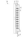
図1Aは、全体が符号10で示される、例示的な流体送達装置(例えば薬物送達装置)の使用前形態の断面図である。図1Bは、流体送達装置10の作動前形態の断面図である。図2は、流体送達装置10の分解断面図である。この例示的な実施形態では、流体送達装置10は、流体送達装置10を形成するために互いに結合された複数のサブアセンブリ部品、例えばコレットアセンブリ12及び流体分配アセンブリ14を含む。コレットアセンブリ12及び流体分配アセンブリ14は、その全体が、それぞれの参照番号で示される。図2に示すように、流体分配アセンブリ14は、複数のさらなるサブアセンブリ部品、例えばプレナムアセンブリ16、カートリッジアセンブリ18、キャップアセンブリ320及び機械的制御アセンブリ20を含む。コレットアセンブリ12、流体分配アセンブリ14、プレナムアセンブリ16、カートリッジアセンブリ18、キャップアセンブリ320、及び機械的制御アセンブリ20の各々は、添付図面において、その全体が、それぞれの参照番号で示される。コレットアセンブリ12は、流体送達装置10の筐体またはハウジングを形成し、流体分配アセンブリ14に摺動可能に取り付けられる。流体分配アセンブリ14を形成するために、キャップアセンブリ320がカートリッジアセンブリ18に結合され、カートリッジアセンブリ18がプレナムアセンブリ16に摺動可能に取り付けられる。加えて、機械的制御アセンブリ20が、以下により詳細に説明するように、カートリッジアセンブリ18に結合される。 FIG. 1A is a cross-sectional view of an exemplary fluid delivery device (eg, drug delivery device) in pre-use form, which is shown entirely by reference numeral 10. FIG. 1B is a cross-sectional view of the pre-operational form of the fluid delivery device 10. FIG. 2 is an exploded sectional view of the fluid delivery device 10. In this exemplary embodiment, the fluid delivery device 10 includes a plurality of subassembly components coupled together to form the fluid delivery device 10, such as a collet assembly 12 and a fluid distribution assembly 14. The collet assembly 12 and the fluid distribution assembly 14 as a whole are indicated by their respective reference numbers. As shown in FIG. 2, the fluid distribution assembly 14 includes a plurality of additional subassembly components such as the plenum assembly 16, the cartridge assembly 18, the cap assembly 320 and the mechanical control assembly 20. Each of the collet assembly 12, the fluid distribution assembly 14, the plenum assembly 16, the cartridge assembly 18, the cap assembly 320, and the mechanical control assembly 20 are all shown in the accompanying drawings by their respective reference numbers. The collet assembly 12 forms the housing or housing of the fluid delivery device 10 and is slidably attached to the fluid distribution assembly 14. To form the fluid distribution assembly 14, the cap assembly 320 is coupled to the cartridge assembly 18 and the cartridge assembly 18 is slidably attached to the plenum assembly 16. In addition, the mechanical control assembly 20 is coupled to the cartridge assembly 18, as described in more detail below.

図3は、流体送達装置10のコレットアセンブリ12の断面図であり、図4は、流体送達装置10のコレットアセンブリ12の分解斜視図である。図2~図4を参照すると、この例示的な実施形態では、コレットアセンブリ12は、コレットロック50と、コレットロック50に結合されたコレット22とを含む。この例示的な実施形態では、コレット22は、略円錐台形状に形成されており、その内部に画定された中空の内部空間24を有する。コレット22は、中心軸線「A」を中心として略対称に形成されている。コレット22の上側リム26が、内部空間24に通じる開口部28を画定する。円筒状の上側壁部30が、上側リム26からコレット22の中央部分32に向かって略垂直下方に延びている。下側壁部34が、中央部分32からコレット22の基部36(下端部)に向かって、外向きの角度で下方に延びている。上側壁部30、中央部分32及び下側壁部34が互いに協働して、内部空間24を画定する。段差部38が上側壁部30の周りに延在し、これにより、本明細書でさらに説明されるように、取付バンド430(図36に示す)と係合するように構成された外側水平面40(コレット外側レッジ)を画定している。また、段差部38は、プレナムアセンブリ16と係合するように構成された内側水平面42(コレット内側段差部)を画定し、これにより、流体送達装置10の使用前に、プレナムアセンブリ16をユーザの皮膚表面上に適切に位置決めすることができる。 FIG. 3 is a cross-sectional view of the collet assembly 12 of the fluid delivery device 10, and FIG. 4 is an exploded perspective view of the collet assembly 12 of the fluid delivery device 10. Referring to FIGS. 2-4, in this exemplary embodiment, the collet assembly 12 includes a collet lock 50 and a collet 22 coupled to the collet lock 50. In this exemplary embodiment, the collet 22 is formed in a substantially truncated cone shape and has a hollow interior space 24 defined therein. The collet 22 is formed substantially symmetrically with the central axis "A" as the center. The upper rim 26 of the collet 22 defines an opening 28 leading to the interior space 24. The cylindrical upper side wall portion 30 extends substantially vertically downward from the upper rim 26 toward the central portion 32 of the collet 22. The lower side wall portion 34 extends downward from the central portion 32 toward the base portion 36 (lower end portion) of the collet 22 at an outward angle. The upper side wall portion 30, the central portion 32, and the lower side wall portion 34 cooperate with each other to define the internal space 24. A step portion 38 extends around the upper side wall portion 30, whereby an outer horizontal plane 40 configured to engage a mounting band 430 (shown in FIG. 36), as further described herein. (Collet outer ledge) is defined. Further, the step portion 38 defines an inner horizontal plane 42 (collet inner step portion) configured to engage the plenum assembly 16, thereby allowing the plenum assembly 16 to be used by the user prior to use of the fluid delivery device 10. Can be properly positioned on the skin surface.

図4に示すように、コレット22は、互いに反対側に位置し、かつ下側壁部34を貫通して形成された、全体が符号44で示される一対のノッチを含む。この例示的な実施形態では、ノッチ44は、略長方形の形状を有し、コレットロック50の一部を受容するように構成されている。加えて、コレット22は、コレット22に結合されたときにコレットロック50を位置決めすることができるように構成された1以上のストップ46を含む。例えば、これに限定しないが、1以上のストップ46は、下側壁部34に形成された、径方向内方に延出する突出部として形成されている。ストップ46は、ストップ46が本明細書で説明されるように機能することを可能にする形態または形状を有することができる。 As shown in FIG. 4, the collet 22 includes a pair of notches located on opposite sides of each other and formed through the lower side wall portion 34 as a whole, indicated by reference numeral 44. In this exemplary embodiment, the notch 44 has a substantially rectangular shape and is configured to receive a portion of the collet lock 50. In addition, the collet 22 includes one or more stops 46 configured to be able to position the collet lock 50 when coupled to the collet 22. For example, without limitation, one or more stops 46 are formed as radial inwardly extending protrusions formed on the lower side wall portion 34. The stop 46 can have a form or shape that allows the stop 46 to function as described herein.

図3及び図4に示すように、コレット22は、上側壁部30と一体的に形成された複数の可撓性タブ48を含む。加えて、複数の可撓性タブ48は、中心軸線「A」を中心として互いに等間隔を隔てて配置されている。具体的には、複数の可撓性タブ48は、第1の端部76からその反対側の自由な第2の端部78まで延在している。この例示的な実施形態では、自由な第2の端部78は、径方向内方に角度をなしており、プレナムアセンブリ16と係合して、流体送達装置10の使用中にプレナムアセンブリ16をユーザの皮膚表面に適切に位置決めすることができるように構成されている。 As shown in FIGS. 3 and 4, the collet 22 includes a plurality of flexible tabs 48 integrally formed with the upper side wall portion 30. In addition, the plurality of flexible tabs 48 are arranged at equal intervals from each other with the central axis "A" as the center. Specifically, the plurality of flexible tabs 48 extend from the first end 76 to the opposite free second end 78. In this exemplary embodiment, the free second end 78 is radially inwardly angled and engages with the plenum assembly 16 to engage the plenum assembly 16 during use of the fluid delivery device 10. It is configured to be properly positioned on the user's skin surface.

図3及び図4に示すように、この例示的な実施形態では、コレットロック50は、略環状の形状に形成されており、その下側外縁54から略円筒状の内壁56まで延在する凸状の内面52を有する。内壁56は、上面58まで上方に延びている。コレットロック50は、内壁56と同心の、かつ下側外縁54から上方に延びる略円筒状の外壁部60を含む。加えて、コレットロック50は、互いに反対側に位置し、かつ上面58から上方に延びるラッチ部材62、64を含む。ラッチ部材62、64は、コレット22のノッチ44と結合するように構成されている。ラッチ部材62は、ラッチ部材62から径方向外方に延出する第1の結合部材66を含む。具体的には、第1の結合部材66は、コレット22の下側壁部34に対して実質的に直交する上向きの角度で延出するネック部分63を含む。加えて、第1の結合部材66は、ネック部分63の周縁部を越えて延出し、かつ下側壁部34に対して略平行に延在するヘッド部分65を含む。さらに、第1の結合部材66は、ヘッド部分65を貫通して延在する開口部またはウィンドウ61を含む。ウィンドウ61は、本明細書でさらに説明されるように、流体送達装置10のユーザに対して取付バンド430の締め付け具合についての表示を提示するように構成されている。 As shown in FIGS. 3 and 4, in this exemplary embodiment, the collet lock 50 is formed in a substantially annular shape and is convex extending from its lower outer edge 54 to a substantially cylindrical inner wall 56. It has a shaped inner surface 52. The inner wall 56 extends upward to the upper surface 58. The collet lock 50 includes a substantially cylindrical outer wall portion 60 that is concentric with the inner wall 56 and extends upward from the lower outer edge 54. In addition, the collet lock 50 includes latch members 62, 64 that are located opposite each other and extend upward from the top surface 58. The latch members 62, 64 are configured to be coupled to the notch 44 of the collet 22. The latch member 62 includes a first coupling member 66 extending radially outward from the latch member 62. Specifically, the first coupling member 66 includes a neck portion 63 extending at an upward angle substantially orthogonal to the lower sidewall portion 34 of the collet 22. In addition, the first coupling member 66 includes a head portion 65 that extends beyond the peripheral edge of the neck portion 63 and extends substantially parallel to the lower side wall portion 34. Further, the first coupling member 66 includes an opening or a window 61 extending through the head portion 65. The window 61 is configured to present the user of the fluid delivery device 10 with an indication of how tight the mounting band 430 is, as further described herein.

同様に、ラッチ部材64は、ラッチ部材64から径方向外方に延出する一対の第2の結合部材68を含む。この例示的な実施形態では、一対の第2の結合部材68の各結合部材は、コレット22の下側壁部34に対して実質的に直交する上向きの角度で延出するネック部分67を含む。加えて、第2の結合部材68は、ネック部分67の周縁部を越えて延出し、かつ下側壁部34に対して略平行に延在するヘッド部分69を含む。第1の結合部材66及び一対の第2の結合部材68は、本明細書でさらに説明されるように、取付バンド430と係合するように構成されている。 Similarly, the latch member 64 includes a pair of second coupling members 68 extending radially outward from the latch member 64. In this exemplary embodiment, each coupling member of the pair of second coupling members 68 includes a neck portion 67 extending at an upward angle substantially orthogonal to the lower sidewall portion 34 of the collet 22. In addition, the second coupling member 68 includes a head portion 69 that extends beyond the peripheral edge of the neck portion 67 and extends substantially parallel to the lower side wall portion 34. The first coupling member 66 and the pair of second coupling members 68 are configured to engage the mounting band 430, as further described herein.

この例示的な実施形態では、コレットロック50の外壁部60は、コレット22の下側壁部34に対して実質的に平行な角度で、径方向内方に傾斜する上側外面70を有し、これにより、コレットロック50の外壁部60とコレット22の下側壁部34とを面対面係合(face-to-face engagement)させることができる。加えて、上面58は、上方に延び、かつコレット22に結合されたときにコレットロック50を適切に位置決めするためにコレット22の1以上のストップ46と係合するように構成された複数のストップ部材72を含む。凸状の内面52から径方向内方に延びる複数の固定タブ74は、プレナムアセンブリ16と係合して、流体送達装置10の使用中にプレナムアセンブリ16をユーザの皮膚表面に適切に位置決めすることができるように構成されている。 In this exemplary embodiment, the outer wall portion 60 of the collet lock 50 has an upper outer surface 70 that is radially inwardly inclined at an angle substantially parallel to the lower side wall portion 34 of the collet 22. As a result, the outer wall portion 60 of the collet lock 50 and the lower side wall portion 34 of the collet 22 can be face-to-face engaged. In addition, the top surface 58 extends upward and is configured to engage one or more stops 46 of the collet 22 to properly position the collet lock 50 when coupled to the collet 22. Includes member 72. A plurality of fixing tabs 74 extending radially inward from the convex inner surface 52 engage with the plenum assembly 16 to properly position the plenum assembly 16 on the user's skin surface during use of the fluid delivery device 10. Is configured to allow

この例示的な実施形態では、コレット22は、コレットロック50に結合されて、一体的なアセンブリ(図3に示す)を形成する。具体的には、コレットロック50の上側外面70及びラッチ部材62、64は、恒久的結合方法、例えば、これに限定しないが、接着剤や溶接結合(例えば、スピン溶接、超音波溶接、レーザ溶接、または熱かしめ)などによって、コレット22の下側壁部34及びノッチ44に結合される。あるいは、コレット22及びコレットロック50は、コレットアセンブリ12の形成を可能にする任意の結合技術を用いて互いに結合される。 In this exemplary embodiment, the collet 22 is coupled to the collet lock 50 to form an integral assembly (shown in FIG. 3). Specifically, the upper outer surface 70 of the collet lock 50 and the latch members 62, 64 are a permanent bonding method, for example, but not limited to, an adhesive or a welding connection (for example, spin welding, ultrasonic welding, laser welding). , Or by heat caulking) or the like, it is coupled to the lower side wall portion 34 and the notch 44 of the collet 22. Alternatively, the collet 22 and the collet lock 50 are coupled to each other using any coupling technique that allows the formation of the collet assembly 12.

図5は、流体送達装置10のプレナムアセンブリ16の断面図である。図6は、プレナムアセンブリ16の分解斜視図である。この例示的な実施形態では、プレナムアセンブリ16は、スリーブ部品100、プレナム部品102、カニューレ104、プレナムキャップアセンブリ106(広義には、「気体抽出装置」)、及びマイクロニードルアレイアセンブリ108を含み、これらは互いに結合されて、一体的なプレナムアセンブリ16を形成する。具体的には、スリーブ部品100は、プレナム部品102に結合されて、その内部にキャビティ110を形成する。この例示的な実施形態では、スリーブ部品100は、例えば、これに限定しないが、接着剤や溶接結合(例えば、スピン溶接、超音波溶接、レーザ溶接、または熱かしめ)などによって、プレナム部品102に結合される。あるいは、スリーブ部品100及びプレナム部品102は、プレナムアセンブリ16の形成を可能にする任意の接続技術を用いて互いに結合される。 FIG. 5 is a cross-sectional view of the plenum assembly 16 of the fluid delivery device 10. FIG. 6 is an exploded perspective view of the plenum assembly 16. In this exemplary embodiment, the plenum assembly 16 includes a sleeve component 100, a plenum component 102, a cannula 104, a plenum cap assembly 106 (in a broad sense, a "gas extractor"), and a microneedle array assembly 108. Are combined with each other to form an integral plenum assembly 16. Specifically, the sleeve component 100 is coupled to the plenum component 102 to form a cavity 110 inside it. In this exemplary embodiment, the sleeve component 100 is attached to the plenum component 102 by, for example, but not limited to, an adhesive or a welded bond (eg, spin weld, ultrasonic weld, laser weld, or heat caulking). Will be combined. Alternatively, the sleeve component 100 and the plenum component 102 are coupled to each other using any connection technique that allows the formation of the plenum assembly 16.

図7は、スリーブ部品100の上面図であり、図8は、スリーブ部品100の底面図であり、図9は、図7の9-9線で切断したスリーブ部品100の断面図であり、図10は、図8の10-10線で切断したスリーブ部品100の断面図である。図5~図10に示すように、この例示的な実施形態では、スリーブ部品100は、環状の下壁部分112及び環状の上壁部分114を含む。上壁部分114は、スリーブ部品100の中心軸線「A」を中心として実質的に軸方向に延び、かつ上壁部分114と一体的に形成された複数の可撓性タブ116を含む。複数の可撓性タブ116は、中心軸線「A」を中心として互いに等間隔を隔てて配置される。添付図面では、4つの可撓性タブ116が図示されているが、他の実施形態では、スリーブ部品100は、スリーブ部品100が本明細書で説明されるように機能することを可能にする任意の数の可撓性タブ116を有することに留意されたい。この例示的な実施形態では、各可撓性タブ116は、第1の端部118からその反対側の自由な第2の端部120まで延在している。自由な第2の端部120は、カートリッジアセンブリ18を使用前形態及び作動前形態において適切に位置決めするためにカートリッジアセンブリ18と係合するように位置決めされた、径方向内方に延出する突出部122を含む。 7 is a top view of the sleeve component 100, FIG. 8 is a bottom view of the sleeve component 100, and FIG. 9 is a cross-sectional view of the sleeve component 100 cut along line 9-9 of FIG. 10 is a cross-sectional view of the sleeve component 100 cut along line 10-10 of FIG. As shown in FIGS. 5-10, in this exemplary embodiment, the sleeve component 100 includes an annular lower wall portion 112 and an annular upper wall portion 114. The upper wall portion 114 includes a plurality of flexible tabs 116 that extend substantially axially about the central axis "A" of the sleeve component 100 and are integrally formed with the upper wall portion 114. The plurality of flexible tabs 116 are arranged at equal intervals from each other with the central axis "A" as the center. In the accompanying drawings, four flexible tabs 116 are illustrated, but in other embodiments, the sleeve component 100 is optional that allows the sleeve component 100 to function as described herein. Note that it has a number of flexible tabs 116. In this exemplary embodiment, each flexible tab 116 extends from the first end 118 to the opposite free second end 120. The free second end 120 extends radially inward, positioned to engage the cartridge assembly 18 for proper positioning of the cartridge assembly 18 in pre-use and pre-operational forms. Includes part 122.

図7に示すように、下壁部分112は、外径124及び内径126を有し、それらの間に複数の凹部128、130、132が画定されている。中心軸線「A」を中心として互いに等間隔を隔てて配置された4組の凹部128、130、132が図示されているが、他の実施形態では、スリーブ部品100は、スリーブ部品100が本明細書で説明されるように機能することを可能にする任意の数の組の凹部128、130、132を有することに留意されたい。下壁部分112はまた、中心軸線「A」を中心として互いに等間隔を隔てて配置された、径方向内方に延びる複数のフランジ部材134を含む。4つのフランジ部材134が図示されているが、他の実施形態では、スリーブ部品100は、スリーブ部品100が本明細書で説明されるように機能することを可能にする任意の数のフランジ部材134を有することに留意されたい。この例示的な実施形態では、フランジ部材134は、プレナム部品102に形成された対応する凹部190と係合して結合するように構成されている。 As shown in FIG. 7, the lower wall portion 112 has an outer diameter 124 and an inner diameter 126, and a plurality of recesses 128, 130, and 132 are defined between them. Although four sets of recesses 128, 130, and 132 arranged at equal intervals from each other about the central axis "A" are shown, in other embodiments, the sleeve component 100 is the sleeve component 100. Note that it has any number of sets of recesses 128, 130, 132 that allow it to function as described in the book. The lower wall portion 112 also includes a plurality of flange members 134 extending inward in the radial direction, arranged at equal intervals from each other about the central axis "A". Although four flange members 134 are illustrated, in other embodiments, the sleeve component 100 allows any number of flange members 134 to allow the sleeve component 100 to function as described herein. Please note that you have. In this exemplary embodiment, the flange member 134 is configured to engage and engage with the corresponding recess 190 formed in the plenum component 102.

この例示的な実施形態では、各凹部128(ポケット)は、下壁部分112に、外径124から下壁部分112の内部に向かって所定の径方向距離138だけ延びる略矩形状の凹部として形成されている。図8に示すように、凹部128は、各フランジ部材134の中心から周方向に角度αだけオフセットされている。図10に最もよく示されているように、凹部128は、スリーブ部品100の底面136から所定の距離140だけ上方に延びており、かつその内部にコレットロック50の各固定タブ74を受容するように構成されている。 In this exemplary embodiment, each recess 128 (pocket) is formed in the lower wall portion 112 as a substantially rectangular recess extending from the outer diameter 124 toward the inside of the lower wall portion 112 by a predetermined radial distance 138. Has been done. As shown in FIG. 8, the recess 128 is offset by an angle α in the circumferential direction from the center of each flange member 134. As best shown in FIG. 10, the recess 128 extends upward by a predetermined distance 140 from the bottom surface 136 of the sleeve component 100 and is inside which each fixing tab 74 of the collet lock 50 is received. It is configured in.

さらに、この例示的な実施形態では、各凹部130は、下壁部分112に形成された平坦面として設けられている。また、凹部130は、底面136から下壁部分112の上面142(スリーブ外側レッジ)まで延びており、かつ中心軸線「A」から延びる径方向線に対して略直交している。図8に示すように、凹部130は、各フランジ部材134の中心から角度βで規定される径方向線に対して略直交するように形成されている。この例示的な実施形態では、凹部130は、プレナムアセンブリ16をコレットアセンブリ12と組み合わせるときに、コレットロック50の各固定タブ74を、スリーブ部品100と干渉することなく軸方向に通過させることができるように構成されている。 Further, in this exemplary embodiment, each recess 130 is provided as a flat surface formed in the lower wall portion 112. Further, the recess 130 extends from the bottom surface 136 to the upper surface 142 (sleeve outer ledge) of the lower wall portion 112, and is substantially orthogonal to the radial line extending from the central axis “A”. As shown in FIG. 8, the recess 130 is formed so as to be substantially orthogonal to the radial line defined by the angle β from the center of each flange member 134. In this exemplary embodiment, the recess 130 allows each fixing tab 74 of the collet lock 50 to pass axially without interfering with the sleeve component 100 when the plenum assembly 16 is combined with the collet assembly 12. It is configured as follows.

また、この例示的な実施形態では、凹部132は、周方向において凹部130から接線方向に延びる円弧状凹部として形成されており、中心軸線「A」に対する連続的な半径を有している。具体的には、凹部132は、プレナムアセンブリ16をコレットアセンブリ12と組み合わせるときに、凹部132がコレットロック50の各固定タブ74を受容することを可能にし、それと同時に、コレット22の各可撓性タブ48が凹部130と整列して受容されることを可能にする円弧状の距離だけ延びている。図6に示すように、凹部132は、底面136から所定の高さ144だけ上方に延びている。 Further, in this exemplary embodiment, the recess 132 is formed as an arcuate recess extending tangentially from the recess 130 in the circumferential direction, and has a continuous radius with respect to the central axis "A". Specifically, the recess 132 allows the recess 132 to receive each fixed tab 74 of the collet lock 50 when the plenum assembly 16 is combined with the collet assembly 12, while at the same time allowing each flexibility of the collet 22. The tab 48 extends by an arcuate distance that allows it to be aligned and received in alignment with the recess 130. As shown in FIG. 6, the recess 132 extends upward from the bottom surface 136 by a predetermined height 144.

下壁部分112はまた、凹部128、130、132によって一部分が画定された複数の突出部またはストップ146を含む。この例示的な実施形態では、各ストップ146は、凹部132の周方向端部148と、その凹部132に隣接する凹部128(図8に示す)との間に延在する。ストップ146は、コレットロック50の固定タブ74が凹部128内または凹部132の周方向端部148に位置したときに、プレナムアセンブリ16の回転を防止するように構成されている。各ストップ146は、略軸方向に延び、かつ中心軸線「A」から延びる径方向線に対して実質的に直交する外面150を含む。加えて、各ストップ146は、外面150から下壁部分112の上面142まで上向きに延びる傾斜面152を含む。ストップ146は、流体送達装置10の組み立て後に、コレットアセンブリ12に対するプレナムアセンブリ16の回転を防止するために、コレット22の可撓性タブ48と係合するように構成されている。図6に示すように、凹部130の表面の一部は、凹部132を越えて周方向に延びて傾斜面152に結合し、これにより、プレナムアセンブリ16をコレットアセンブリ12に組み合わせるときにコレット22の可撓性タブ48と係合するように構成されたランプとして機能する。 The lower wall portion 112 also includes a plurality of protrusions or stops 146 partially defined by recesses 128, 130, 132. In this exemplary embodiment, each stop 146 extends between the circumferential end 148 of the recess 132 and the recess 128 (shown in FIG. 8) adjacent to the recess 132. The stop 146 is configured to prevent rotation of the plenum assembly 16 when the fixing tab 74 of the collet lock 50 is located within the recess 128 or at the circumferential end 148 of the recess 132. Each stop 146 includes an outer surface 150 extending substantially axially and substantially orthogonal to a radial line extending from the central axis "A". In addition, each stop 146 includes an inclined surface 152 extending upward from the outer surface 150 to the upper surface 142 of the lower wall portion 112. The stop 146 is configured to engage the flexible tab 48 of the collet 22 to prevent rotation of the plenum assembly 16 with respect to the collet assembly 12 after assembly of the fluid delivery device 10. As shown in FIG. 6, a portion of the surface of the recess 130 extends circumferentially beyond the recess 132 and couples to the inclined surface 152, whereby the collet 22 when the plenum assembly 16 is combined with the collet assembly 12. It functions as a lamp configured to engage the flexible tab 48.

図11は、プレナム部品102の上面図であり、図12は、プレナム部品102の底面図であり、図13は、図11の13-13線で切断したプレナム部品102の断面図である。図5、図6、及び図11~図13を参照すると、この例示的な実施形態では、プレナム部品102は、底面136に隣接するスリーブ部品100の下壁部分112を水平方向に横断して延在してキャビティ110を画定する略円板状の本体部分160を含む。本体部分160は、上面162(図11)と、その反対側の下面164(図12)とを含む。プレナム部品102の上面162は、本体部分160の中央部分の近傍に配置されてチャンバ167を画定する、上方に延びる環状中央壁部166を有する。環状中央壁部166は、カートリッジアセンブリ18と結合されるように構成された上側リム168を含む。プレナム部品102の下面164は、本体部分160から下方に延びる矩形状のフレーム部分170を含む。フレーム部分170は、プレナムキャップアセンブリ106及びマイクロニードルアレイアセンブリ108をプレナム部品102内に位置する取付面174に取り付けるための取付空間172を画定する。 11 is a top view of the plenum component 102, FIG. 12 is a bottom view of the plenum component 102, and FIG. 13 is a cross-sectional view of the plenum component 102 cut along the line 13-13 of FIG. Referring to FIGS. 5, 6 and 11-13, in this exemplary embodiment, the plenum component 102 extends horizontally across the lower wall portion 112 of the sleeve component 100 adjacent to the bottom surface 136. Includes a substantially disk-shaped body portion 160 that is present and defines the cavity 110. The main body portion 160 includes an upper surface 162 (FIG. 11) and a lower surface 164 (FIG. 12) on the opposite side thereof. The top surface 162 of the plenum component 102 has an upwardly extending annular central wall portion 166 that is located near the central portion of the body portion 160 and defines the chamber 167. The annular central wall portion 166 includes an upper rim 168 configured to be coupled to the cartridge assembly 18. The lower surface 164 of the plenum component 102 includes a rectangular frame portion 170 extending downward from the body portion 160. The frame portion 170 defines a mounting space 172 for mounting the plenum cap assembly 106 and the microneedle array assembly 108 on the mounting surface 174 located within the plenum component 102.

プレナム部品102は、軸方向に延在する複数の開口部178を有する円弧状のチャネル176を含む。具体的には、図12に最もよく示されているように、円弧状のチャネル176は、取付空間172内の取付面174に形成されている。円弧状のチャネル176は、中心半径180(流体通路186から所定半径離れた位置を結ぶ円弧状の線)を中心とする所定の幅を有する。中心半径180は、プレナム部品102の中心軸線「A」と同心である。この例示的な実施形態では、円弧状のチャネル176は、周方向に約270°の角度にわたって延在している。他の実施形態では、円弧状のチャネル176は、プレナム部品102が本明細書で説明されるように機能することを可能にする任意の円周角度にわたって延在することができる。この例示的な実施形態では、軸方向に延在する複数の開口部178は、円弧状のチャネル176内に均等に配置される。各開口部178は、その中心を中心半径180上に置いて、下面164から上面162まで本体部分160を貫通して延在している。この例示的な実施形態では、プレナム部品102は、軸方向に延在する10個の開口部178を含む。あるいは、他の適切な実施形態では、プレナム部品102は、プレナム部品102が本明細書で説明されるように機能することを可能にする任意の数の軸方向に延在する開口部178を含むことができる。 The plenum component 102 includes an arcuate channel 176 with a plurality of axially extending openings 178. Specifically, as best shown in FIG. 12, the arcuate channel 176 is formed on the mounting surface 174 in the mounting space 172. The arc-shaped channel 176 has a predetermined width centered on a central radius of 180 (an arc-shaped line connecting positions separated from the fluid passage 186 by a predetermined radius). The central radius 180 is concentric with the central axis "A" of the plenum component 102. In this exemplary embodiment, the arcuate channel 176 extends circumferentially over an angle of about 270 °. In another embodiment, the arcuate channel 176 can extend over any angle of circumference that allows the plenum component 102 to function as described herein. In this exemplary embodiment, the plurality of axially extending openings 178 are evenly arranged within the arcuate channel 176. Each opening 178 has its center placed on a central radius of 180 and extends from the lower surface 164 to the upper surface 162 through the main body portion 160. In this exemplary embodiment, the plenum component 102 includes 10 axially extending openings 178. Alternatively, in another suitable embodiment, the plenum component 102 includes any number of axially extending openings 178 that allow the plenum component 102 to function as described herein. be able to.

この例示的な実施形態では、図5に最もよく示されているように、カニューレ104は、プレナム部品102の上面162から上方に延びる取付部184に結合される。具体的には、カニューレ104は、中心軸線「A」と同軸に、かつプレナム部品102を貫通して延在する流体通路186と流体連通して結合される。カニューレ104は、取付部184との締まりばめ、及び取付部184内に画定されたキャビティ188内に配置された接着剤によって、プレナム部品102に結合される。本明細書中で使用するとき、用語「締まりばめ」は、カニューレ104と取付部184との間の密着度の値、すなわち、部品間の径方向のクリアランスの量を意味する。クリアランスの負の値は、一般にプレスフィットと呼ばれ、締まりの大きさによって、軽い締まりばめであるか、または締まりばめであるかが決定される。少量の正のクリアランスは、ルーズフィットまたはスライディングフィットと呼ばれる。あるいは、カニューレ104は、プレナム部品102が本明細書で説明されるように機能することを可能にする任意の適切な締結技術を用いて、取付部184に結合させることができる。この例示的な実施形態では、カニューレ104の上側部分は、鋭く尖っており、プレナム部品102から遠ざかるように上方に延びている。これにより、本明細書で説明されるように、カニューレ104は、カートリッジアセンブリ18の一部を貫通することができる。 In this exemplary embodiment, as best shown in FIG. 5, the cannula 104 is coupled to a mounting portion 184 extending upward from the top surface 162 of the plenum component 102. Specifically, the cannula 104 is coupled coaxially with the central axis "A" and in fluid communication with a fluid passage 186 extending through the plenum component 102. The cannula 104 is coupled to the plenum component 102 by a tight fit with the mounting portion 184 and an adhesive placed in the cavity 188 defined within the mounting portion 184. As used herein, the term "tight fit" means the value of the degree of adhesion between the cannula 104 and the mounting portion 184, i.e., the amount of radial clearance between the parts. A negative value of clearance is commonly referred to as a press fit, and the size of the tightness determines whether it is a light tight fit or a tight fit. A small amount of positive clearance is called a loose fit or sliding fit. Alternatively, the cannula 104 can be coupled to the attachment portion 184 using any suitable fastening technique that allows the plenum component 102 to function as described herein. In this exemplary embodiment, the upper portion of the cannula 104 is sharply pointed and extends upward away from the plenum component 102. This allows the cannula 104 to penetrate a portion of the cartridge assembly 18, as described herein.

図11を参照すると、プレナム部品102は、上面162に形成され、かつ中心軸線「A」を中心として互いに等間隔を隔てて配置された複数の凹部190を含む。凹部190は、上述したように、スリーブ部品100のフランジ部材134に対応するサイズ及び形状に形成されている。具体的には、この例示的な実施形態では、プレナム部品102は、図示した4つの凹部190を含むが、他の実施形態では、プレナム部品102は、プレナム部品102が本明細書で説明されるように機能することを可能にする任意の数の凹部190を有することに留意されたい。本明細書で説明されるように、スリーブ部品100は、例えば、これに限定しないが、接着剤や溶接結合(例えば、スピン溶接、超音波溶接、レーザ溶接、または熱かしめ)などによって、プレナム部品102に結合される。具体的には、スリーブ部品100のフランジ部材134は、プレナム部品102の凹部190に結合されて、一体的なアセンブリを形成する。 Referring to FIG. 11, the plenum component 102 includes a plurality of recesses 190 formed on the upper surface 162 and arranged at equal intervals with respect to the central axis "A". As described above, the recess 190 is formed in a size and shape corresponding to the flange member 134 of the sleeve component 100. Specifically, in this exemplary embodiment, the plenum component 102 includes the four recesses 190 illustrated, whereas in other embodiments, the plenum component 102 is described herein by the plenum component 102. Note that it has any number of recesses 190 that allow it to function as such. As described herein, the sleeve component 100 is a plenum component, for example, but not limited to, by an adhesive or a welded bond (eg, spin weld, ultrasonic weld, laser weld, or heat caulking). Combined with 102. Specifically, the flange member 134 of the sleeve component 100 is coupled to the recess 190 of the plenum component 102 to form an integral assembly.

図14は、図1Aに示した流体送達装置10のプレナムキャップアセンブリ106の概略分解図である。図15は、プレナムキャップアセンブリ106の上面図である。この例示的な実施形態では、プレナムキャップアセンブリ106は、互いに結合された複数の層を含む一体的なアセンブリである。プレナムキャップアセンブリ106は、感圧接着フィルムから作製された第1の接着層192によって、プレナム部品102の取付面174に結合される。第1の接着層192は、該第1の接着層192を貫通して形成された円弧状のスロット202(気体抽出装置の気体抽出流路)を含む。円弧状のスロット202は、中心軸線「A」と同軸に形成された開口部204と実質的に同心に配置される。円弧状のスロット202は、中心半径206(開口部204から所定半径離れた位置を結ぶ円弧状の線)を中心とする所定の幅を有する。中心半径206は、中心軸線「A」と同心である。この例示的な実施形態では、円弧状のスロット202は角度θにわたって周方向に延在する。他の実施形態では、円弧状のスロット202は、プレナムキャップアセンブリ106が本明細書で説明されるように機能することを可能にする任意の円周角度θにわたって延在することができる。この例示的な実施形態では、円弧状のスロット202は、プレナム部品102の円弧状のチャネル176と少なくとも部分的に対応するように構成され、開口部204は、プレナム部品102の流体通路186に対応するように配置される。 FIG. 14 is a schematic exploded view of the plenum cap assembly 106 of the fluid delivery device 10 shown in FIG. 1A. FIG. 15 is a top view of the plenum cap assembly 106. In this exemplary embodiment, the plenum cap assembly 106 is an integral assembly that includes a plurality of layers joined together. The plenum cap assembly 106 is coupled to the mounting surface 174 of the plenum component 102 by a first adhesive layer 192 made from a pressure sensitive adhesive film. The first adhesive layer 192 includes an arcuate slot 202 (gas extraction flow path of a gas extractor) formed through the first adhesive layer 192. The arcuate slot 202 is substantially concentric with the opening 204 formed coaxially with the central axis "A". The arcuate slot 202 has a predetermined width centered on a center radius 206 (an arcuate line connecting positions separated from the opening 204 by a predetermined radius). The central radius 206 is concentric with the central axis "A". In this exemplary embodiment, the arcuate slot 202 extends circumferentially over an angle θ. In another embodiment, the arcuate slot 202 can extend over any angle of circumference θ that allows the plenum cap assembly 106 to function as described herein. In this exemplary embodiment, the arcuate slot 202 is configured to at least partially correspond to the arcuate channel 176 of the plenum component 102, and the opening 204 corresponds to the fluid passage 186 of the plenum component 102. Arranged to do.

プレナムキャップアセンブリ106は、プレナム部品102の反対側に、第1の接着層192に結合されたベント膜194を含む。この例示的な実施形態では、ベント膜194は、中心軸線「A」と同軸に形成された流体入口開口部208を含む。この例示的な実施形態では、流体入口開口部208は、第1の接着層192の開口部204と実質的に同一のサイズを有する。適切な一実施形態では、ベント膜194は、疎油性/疎水性の気体透過性材料から作製される。他の実施形態では、他の種類の適切な材料を使用してもよいことを理解されたい。例えば、これに限定しないが、一実施形態では、ベント膜194は、ナイロン支持材料、例えば米国ニューヨーク州ポートワシントン所在のポール・コーポレーション社(Pall Corporation)から入手可能なVersapor(登録商標)Membrane上に形成されたアクリルコポリマー膜から作製される。この例示的な実施形態では、ベント膜194の孔径は、約0.2マイクロメートル(ミクロン)である。ベント膜194は、約150キロパスカル(kPa)で測定した場合に、約200~2000mL/分/cmの範囲の空気流量を有する。加えて、ベント膜194は、約35~300kPaの範囲の最小流体気泡圧力を有する。適切な一実施形態では、ベント膜194は、約150kPaで測定した場合に、少なくとも250mL/分/cmの空気流量と、少なくとも150kPaの最小流体気泡圧とを有する。あるいは、ベント膜194は、プレナムキャップアセンブリ106が本明細書で説明されるように機能することを可能にする任意の気体透過性材料から作製することができる。 The plenum cap assembly 106 includes a vent film 194 bonded to the first adhesive layer 192 on the opposite side of the plenum component 102. In this exemplary embodiment, the vent membrane 194 includes a fluid inlet opening 208 formed coaxially with the central axis "A". In this exemplary embodiment, the fluid inlet opening 208 has substantially the same size as the opening 204 of the first adhesive layer 192. In one suitable embodiment, the vent membrane 194 is made from an oleophobic / hydrophobic gas permeable material. It should be understood that in other embodiments, other types of suitable materials may be used. For example, but not limited to, in one embodiment, the vent membrane 194 is on a nylon support material, eg, Versapor® Membrane available from Pall Corporation in Port Washington, NY, USA. It is made from the formed acrylic copolymer membrane. In this exemplary embodiment, the vent membrane 194 has a pore size of about 0.2 micrometer (micron). Vent membrane 194 has an air flow rate in the range of about 200-2000 mL / min / cm 2 when measured at about 150 kilopascals (kPa). In addition, the vent membrane 194 has a minimum fluid bubble pressure in the range of about 35-300 kPa. In one suitable embodiment, the vent membrane 194 has an air flow rate of at least 250 mL / min / cm 2 and a minimum fluid bubble pressure of at least 150 kPa when measured at about 150 kPa. Alternatively, the vent membrane 194 can be made from any gas permeable material that allows the plenum cap assembly 106 to function as described herein.

図16は、プレナムキャップアセンブリ106の第2の接着層196の上面図である。この例示的な実施形態では、第2の接着層196は、感圧接着フィルムから形成され、第1の接着層192の反対側でベント膜194に結合される。第2の接着層196は、第1の接着層192と同様に形成され、該第2の接着層196を貫通して形成された円弧状のスロット210を含む。円弧状のスロット210は、流体から気体を除去するために、中心軸線「A」に対して略直交する方向に延びる蛇行流路を形成するように構成されている。円弧状のスロット210は、第1の接着層192のスロット202に実質的に対応するサイズに形成され、かつスロット202に実質的に対応して配置される。スロット210は、中心軸線「A」と同軸に形成された中央開口部212と同心に配置される。円弧状のスロット210の第1の端部214は、直線状のスロット部216によって中央開口部212に接続される。円弧状のスロット210は、第1の接着層192の中心半径206に対応する中心半径218(中央開口部212から所定半径離れた位置を結ぶ円弧状の線)を中心とする所定の幅を有する。この例示的な実施形態では、円弧状のスロット210は、円弧状のスロット202と同じ角度θにわたって周方向に延在する。他の実施形態では、円弧状のスロット210は、プレナムキャップアセンブリ106が本明細書で説明されるように機能することを可能にする任意の円周角度にわたって延在することができる。 FIG. 16 is a top view of the second adhesive layer 196 of the plenum cap assembly 106. In this exemplary embodiment, the second adhesive layer 196 is formed from a pressure sensitive adhesive film and is attached to the vent film 194 on the opposite side of the first adhesive layer 192. The second adhesive layer 196 is formed in the same manner as the first adhesive layer 192, and includes an arcuate slot 210 formed through the second adhesive layer 196. The arcuate slot 210 is configured to form a meandering flow path extending in a direction substantially orthogonal to the central axis "A" in order to remove gas from the fluid. The arcuate slot 210 is formed in a size substantially corresponding to the slot 202 of the first adhesive layer 192, and is arranged substantially corresponding to the slot 202. The slot 210 is arranged concentrically with the central opening 212 formed coaxially with the central axis "A". The first end 214 of the arcuate slot 210 is connected to the central opening 212 by a linear slot portion 216. The arcuate slot 210 has a predetermined width centered on a central radius 218 (an arcuate line connecting positions separated from the central opening 212 by a predetermined radius) corresponding to the central radius 206 of the first adhesive layer 192. .. In this exemplary embodiment, the arcuate slot 210 extends circumferentially over the same angle θ as the arcuate slot 202. In another embodiment, the arcuate slot 210 can extend over any angle of circumference that allows the plenum cap assembly 106 to function as described herein.

プレナムキャップアセンブリ106は、ベント膜194の反対側で第2の接着層196に結合された不透過性膜198を含む。この例示的な実施形態では、不透過性膜198は、円弧状のスロット210の第2の端部220と同軸に形成された流体出口開口部222を含む。この例示的な実施形態では、流体出口開口部222は、第1の接着層192の開口部204及びベント膜194の流体入口開口部208と実質的に同一のサイズを有する。不透過性膜198は、気体及び液体不透過性材料から作製される。例えば、これに限定しないが、一実施形態では、不透過性膜198は、ポリエチレンテレフタレート(PET)フィルムから作製される。あるいは、不透過性膜198は、プレナムキャップアセンブリ106が本明細書で説明されるように機能することを可能にする任意の気体及び液体不透過性材料から作製することができる。 The plenum cap assembly 106 includes an impermeable membrane 198 bonded to a second adhesive layer 196 on the opposite side of the vent membrane 194. In this exemplary embodiment, the impermeable film 198 includes a fluid outlet opening 222 formed coaxially with the second end 220 of the arcuate slot 210. In this exemplary embodiment, the fluid outlet opening 222 has substantially the same size as the opening 204 of the first adhesive layer 192 and the fluid inlet opening 208 of the vent membrane 194. The impermeable film 198 is made of gas and liquid impermeable materials. For example, but not limited to, in one embodiment, the impermeable membrane 198 is made from a polyethylene terephthalate (PET) film. Alternatively, the impermeable film 198 can be made from any gas and liquid impermeable material that allows the plenum cap assembly 106 to function as described herein.

図17は、プレナムキャップアセンブリ106の第3の接着層200の上面図である。この例示的な実施形態では、第3の接着層200は、感圧接着フィルムから形成され、第2の接着層196の反対側で不透過性膜198に結合される。第3の接着層200は、該第3の接着層200を貫通して形成されたスロット224(流体送達装置10の第2のチャネル)を含む。スロット224は、不透過性膜198の流体出口開口部222に実質的に対応するサイズに形成され、かつ流体出口開口部222に実質的に対応して配置された第1の端部226を含む。加えて、スロット224は、第1の端部226から第2の端部228まで延在する全半径端部を含む。第2の端部228は、第1の接着層192の開口部204及びベント膜194の流体入口開口部208と実質的に同様のサイズを有する。さらに、第2の端部228は、中心軸線「A」と実質的に同軸に配置される。 FIG. 17 is a top view of the third adhesive layer 200 of the plenum cap assembly 106. In this exemplary embodiment, the third adhesive layer 200 is formed from a pressure sensitive adhesive film and is attached to the impermeable membrane 198 on the opposite side of the second adhesive layer 196. The third adhesive layer 200 includes a slot 224 (second channel of the fluid delivery device 10) formed through the third adhesive layer 200. Slot 224 includes a first end 226 formed to a size substantially corresponding to the fluid outlet opening 222 of the impermeable film 198 and disposed substantially corresponding to the fluid outlet opening 222. .. In addition, slot 224 includes a full radius end extending from the first end 226 to the second end 228. The second end 228 has substantially the same size as the opening 204 of the first adhesive layer 192 and the fluid inlet opening 208 of the vent membrane 194. Further, the second end 228 is arranged substantially coaxially with the central axis "A".

図5及び図6を参照して本明細書で説明したように、プレナムアセンブリ16は、プレナムキャップアセンブリ106に結合されるマイクロニードルアレイアセンブリ108を含み、このマイクロニードルアレイアセンブリ108は、プレナム部品102の取付面174に取り付けられる。図18は、図1Aに示した流体送達装置10のマイクロニードルアレイアセンブリ108の概略分解図である。図19Aは、マイクロニードルアレイアセンブリ108の概略断面図である。この例示的な実施形態では、マイクロニードルアレイアセンブリ108は、プレナムキャップアセンブリ106の第3の接着層200によってプレナムキャップアセンブリ106に結合される。マイクロニードルアレイアセンブリ108は、マイクロニードルアレイ230と、マイクロニードルアレイ230の複数のマイクロニードル234及びベース表面236を少なくとも部分的に覆うドレープ膜232とを含む。マイクロニードルアレイアセンブリ108はまた、マイクロニードルアレイ230の背面240を覆うように延在し、かつ背面240に接着層242によって結合される分配マニホールド238を含む。分配マニホールド238は、マイクロニードルアレイ230に流体を供給するための流体分配ネットワーク244を含む。分配マニホールド238から供給される流体は、液体薬物製剤であり得る。ドレープ膜232で覆われたマイクロニードル234は、例えば、各マイクロニードル234に形成された1以上の開口部または流路246を通じて液体薬物製剤をユーザの皮膚に提供するために、ユーザの皮膚を穿孔するように構成されている。 As described herein with reference to FIGS. 5 and 6, the plenum assembly 16 includes a microneedle array assembly 108 coupled to a plenum cap assembly 106, which microneedle array assembly 108 is a plenum component 102. It is mounted on the mounting surface 174 of. FIG. 18 is a schematic exploded view of the microneedle array assembly 108 of the fluid delivery device 10 shown in FIG. 1A. FIG. 19A is a schematic cross-sectional view of the microneedle array assembly 108. In this exemplary embodiment, the microneedle array assembly 108 is coupled to the plenum cap assembly 106 by a third adhesive layer 200 of the plenum cap assembly 106. The microneedle array assembly 108 includes a microneedle array 230 and a drape membrane 232 that at least partially covers the plurality of microneedles 234 and the base surface 236 of the microneedle array 230. The microneedle array assembly 108 also includes a distribution manifold 238 that extends over the back surface 240 of the microneedle array 230 and is coupled to the back surface 240 by an adhesive layer 242. The distribution manifold 238 includes a fluid distribution network 244 for supplying fluid to the microneedle array 230. The fluid supplied from the distribution manifold 238 can be a liquid drug formulation. The microneedle 234 covered with the drape membrane 232 perforates the user's skin, for example, to provide the liquid drug formulation to the user's skin through one or more openings or channels 246 formed in each microneedle 234. It is configured to do.

この例示的な実施形態では、ドレープ膜232は、ポリマー(例えばプラスチック)フィルムなどから作製することができ、追加の接着層242を使用してマイクロニードルアレイ230に結合される。他の実施形態では、ドレープ膜232は、エンボス加工またはナノインプリントされたポリマー(例えばプラスチック)フィルムから作製され得る。または、ドレープ膜232は、ポリエーテルエーテルケトン(PEEK)フィルムから作製され得る。または、ドレープ膜232は、ポリプロピレンフィルムなどの任意の他の適切な材料から作製され得る。マイクロニードルアレイアセンブリ108は、いくつかの実施形態では、ドレープ膜232を含まないことも考えられる。 In this exemplary embodiment, the drape membrane 232 can be made from a polymer (eg, plastic) film or the like and is attached to the microneedle array 230 using an additional adhesive layer 242. In other embodiments, the drape film 232 can be made from an embossed or nanoimprinted polymer (eg, plastic) film. Alternatively, the drape membrane 232 can be made from a polyetheretherketone (PEEK) film. Alternatively, the drape membrane 232 can be made from any other suitable material such as polypropylene film. It is also conceivable that the microneedle array assembly 108 does not include the drape membrane 232 in some embodiments.

この例示的な実施形態では、マイクロニードルアレイ230は、剛性、半剛性または可撓性の材料シート、例えば、これに限定しないが、金属材料、セラミック材料、ポリマー(例えばプラスチック)材料、またはマイクロニードルアレイ230が本明細書で説明されるように機能することを可能にする任意の他の適切な材料から作製され得る。例えば、適切な一実施形態では、マイクロニードルアレイ230は、反応性イオンエッチング、または任意の他の適切な作製技術によって、シリコンから形成され得る。 In this exemplary embodiment, the microneedle array 230 is a rigid, semi-rigid or flexible material sheet, eg, but not limited to, a metal material, a ceramic material, a polymer (eg plastic) material, or a microneedle. The array 230 can be made from any other suitable material that allows it to function as described herein. For example, in one suitable embodiment, the microneedle array 230 may be formed from silicon by reactive ion etching, or any other suitable fabrication technique.

図19Aに示すように、マイクロニードルアレイ230は、マイクロニードルアレイ230の背面240から外向きに延出する複数のマイクロニードル234を含む。マイクロニードルアレイ230は、流体がマイクロニードルアレイ230を貫通して流れることを可能にするための、背面240との間に延在する複数の流路246を含む。例えば、この例示的な実施形態では、各流路246は、マイクロニードルアレイ230及びマイクロニードル234を貫通して延在する。 As shown in FIG. 19A, the microneedle array 230 includes a plurality of microneedle 234s extending outward from the back surface 240 of the microneedle array 230. The microneedle array 230 includes a plurality of flow paths 246 extending between the back surface 240 and the back surface 240 to allow fluid to flow through the microneedle array 230. For example, in this exemplary embodiment, each flow path 246 extends through the microneedle array 230 and the microneedle 234.

各マイクロニードル234は、背面240から下方に延出し、背面240から遠位にある先端部248を有する尖ったまたは針状の形状(例えば、円錐形状若しくはピラミッド形状、または、円錐形状若しくはピラミッド形状に遷移する円筒形状)に遷移する基部を含む。各マイクロニードル234の先端部248は、マイクロニードルアレイ230から最も離れた位置に位置し、各マイクロニードル234の最小寸法(例えば、直径または断面幅)を規定する。加えて、各マイクロニードル234は、マイクロニードル234がユーザの皮膚を穿通する、すなわちマイクロニードル234が角質層を貫通してユーザの表皮に入るのに十分な、マイクロニードルアレイ230のベース表面236と先端部248との間の任意の適切な長さ「L」を概ね規定する。マイクロニードル234の長さLは、マイクロニードル234が表皮の内面を貫通して真皮内に入らないように制限することが望ましく、このことにより、有利なことにユーザの痛みを最小限に抑えることができる。この例示的な実施形態では、各マイクロニードル234は、約1000μm(マイクロメートル)未満、または約800μm未満、または約750μm未満、または約500μm未満の、またはそれらの間の任意の他のサブレンジの長さL(例えば、約200~400μmの範囲の全長L)を有する。マイクロニードル234の全長Lは、流体送達装置10が使用されるユーザの身体の位置に応じて様々であり得る。例えば、これに限定しないが、ユーザの脚に使用される流体送達装置用のマイクロニードル234の全長Lは、ユーザの腕に使用される流体送達装置用のマイクロニードル234の全長Lと実質的に異なり得る。各マイクロニードル234は、一般に、任意の適切なアスペクト比(すなわち、各マイクロニードル234の断面幅寸法Dに対する長さLの比)を有し得る。アスペクト比は2より大きくてもよく、例えば3より大きくてもよく、または4より大きくてもよい。断面幅寸法(例えば直径)が各マイクロニードル234の長さにわたって変化する場合、アスペクト比は、平均断面幅寸法に基づいて決定され得る。 Each microneedle 234 extends downward from the dorsal 240 and has a pointed or needle-like shape (eg, conical or pyramidal, or conical or pyramidal) with a tip 248 distal to the dorsal 240. Includes a base that transitions to a transitioning cylindrical shape). The tip 248 of each microneedle 234 is located farthest from the microneedle array 230 and defines the minimum dimension (eg, diameter or cross-sectional width) of each microneedle 234. In addition, each microneedle 234 and the base surface 236 of the microneedle array 230 are sufficient for the microneedle 234 to penetrate the user's skin, i.e. the microneedle 234 penetrate the stratum corneum and enter the user's epidermis. Any suitable length "L" between the tip and the tip 248 is generally defined. The length L of the microneedle 234 should be restricted so that the microneedle 234 does not penetrate the inner surface of the epidermis and enter the dermis, which advantageously minimizes user pain. Can be done. In this exemplary embodiment, each microneedle 234 is less than about 1000 μm (micrometers), or less than about 800 μm, or less than about 750 μm, or less than about 500 μm, or the length of any other subrange between them. It has a total length L (for example, a total length L in the range of about 200 to 400 μm). The overall length L of the microneedle 234 may vary depending on the position of the user's body in which the fluid delivery device 10 is used. For example, but not limited to, the overall length L of the microneedle 234 for the fluid delivery device used on the user's leg is substantially the overall length L of the microneedle 234 for the fluid delivery device used on the user's arm. Can be different. Each microneedle 234 may generally have any suitable aspect ratio (ie, the ratio of length L to cross-sectional width dimension D of each microneedle 234). The aspect ratio may be greater than 2, for example greater than 3, or greater than 4. If the cross-sectional width dimension (eg, diameter) varies over the length of each microneedle 234, the aspect ratio can be determined based on the average cross-sectional width dimension.

各マイクロニードル234のチャネルまたは流路246は、各マイクロニードルが中空シャフトを形成するようにマイクロニードル234の内部を貫通して形成されるか、または、マイクロニードルの外面に沿って延在するように形成されている。これにより、流体がマイクロニードルアレイ230の背面240から流路246を通って流れることを可能にし、かつ、ユーザの皮膚上に、皮膚内に、及び/または皮膚を貫通して流体を送達することができる下流経路が形成されている。流路246は、任意の適切な断面形状、例えば、これに限定しないが、半円形または円形の形状を画定するように構成され得る。あるいは、各流路246は、非円形形状、例えば、「V」形状、またはマイクロニードル234が本明細書で説明されるように機能することを可能にする任意の他の適切な断面形状を画定するように構成され得る。 The channel or flow path 246 of each microneedle 234 is formed so as to penetrate the inside of the microneedle 234 so that each microneedle forms a hollow shaft, or extend along the outer surface of the microneedle. Is formed in. This allows the fluid to flow from the back surface 240 of the microneedle array 230 through the flow path 246 and to deliver the fluid onto, into, and / or through the skin of the user. A downstream route is formed. The flow path 246 may be configured to define any suitable cross-sectional shape, eg, but not limited to, a semi-circular or circular shape. Alternatively, each flow path 246 defines a non-circular shape, eg, a "V" shape, or any other suitable cross-sectional shape that allows the microneedle 234 to function as described herein. Can be configured to.

マイクロニードルアレイ230は、一般に、背面240から延出する任意の適切な数のマイクロニードル234を含み得る。例えば、いくつかの適切な実施形態では、マイクロニードルアレイ230に含まれるマイクロニードル234の数は、1平方センチメートル当たり約10~1、500個の範囲、例えば約50~1250個、または約100~500個、またはそれらの間の任意の他のサブレンジであり得る。 The microneedle array 230 may generally include any suitable number of microneedles 234 extending from the back surface 240. For example, in some suitable embodiments, the number of microneedles 234 contained in the microneedle array 230 ranges from about 10 to 1,500 per square centimeter, such as about 50 to 1250, or about 100 to 500. Can be pieces, or any other subrange between them.

マイクロニードル234は、一般に、様々なパターンで配置され得る。例えば、いくつかの適切な実施形態では、マイクロニードル234は、長方形または正方形のグリッド、または同心円などの均一な態様で互いに間隔を隔てて配置される。このような実施形態では、マイクロニードル234の間隔は、一般に、これに限定しないが、マイクロニードル234の長さ及び幅、並びに、マイクロニードル234を通じてまたはマイクロニードル234に沿って送達することが意図される液体製剤の量及び種類などの様々な因子に依存し得る。 The microneedles 234 can generally be arranged in various patterns. For example, in some suitable embodiments, the microneedles 234 are spaced apart from each other in a uniform manner, such as a rectangular or square grid, or concentric circles. In such embodiments, the spacing of the microneedles 234 is generally, but not limited to, intended to deliver the length and width of the microneedle 234, as well as through or along the microneedle 234. It may depend on various factors such as the amount and type of liquid formulation.

さらに、この例示的な実施形態では、流体分配ネットワーク244は、例えば、分配マニホールド238の上面250と底面252との間に延在する複数のチャネル及び/または開口部を含む。チャネル及び/または開口部は、中央に配置された入口チャネル254を含む。入口チャネル254は、複数の供給チャネル256、及びプレナムキャップアセンブリ106の第3の接着層200に形成されたスロット224(図14に示す)と流体連通される。この例示的な実施形態では、供給チャネル256は、入口チャネル254から供給された流体を、分配マニホールド238の所定範囲にわたって分配することができる。供給チャネル256の各々は、複数の抵抗チャネル(図示しない)と流体連通される。抵抗チャネルは、供給チャネル256から離間する方向に延び、流体の流れに対する流体分配ネットワーク244の抵抗を増大させるように形成されている。各抵抗チャネルは、出口チャネル258と流体連通される。図19Aに示すように、各出口チャネル258は、マイクロニードル234の流路246を通じて流体を分配するために、各マイクロニードル234と整列されている。他の実施形態では、抵抗チャネル及びチャネル254、256及び258は、分配マニホールド238が本明細書で説明されるように機能することを可能にする任意の構成で形成され得る。 Further, in this exemplary embodiment, the fluid distribution network 244 includes, for example, a plurality of channels and / or openings extending between the top surface 250 and the bottom surface 252 of the distribution manifold 238. The channel and / or opening includes a centrally located inlet channel 254. The inlet channel 254 is fluid communicated with a plurality of supply channels 256 and a slot 224 (shown in FIG. 14) formed in the third adhesive layer 200 of the plenum cap assembly 106. In this exemplary embodiment, the supply channel 256 can distribute the fluid supplied from the inlet channel 254 over a predetermined range of the distribution manifold 238. Each of the supply channels 256 is fluid communicated with a plurality of resistance channels (not shown). The resistance channel extends away from the supply channel 256 and is formed to increase the resistance of the fluid distribution network 244 to the flow of fluid. Each resistance channel is in fluid communication with the outlet channel 258. As shown in FIG. 19A, each outlet channel 258 is aligned with each microneedle 234 to distribute fluid through the flow path 246 of the microneedle 234. In other embodiments, the resistance channels and channels 254, 256 and 258 may be formed in any configuration that allows the distribution manifold 238 to function as described herein.

この例示的な実施形態では、分配マニホールド238は、ベース基板260(ベース基板260を貫通して形成された入口チャネル254と、ベース基板260の底面264に形成された供給チャネル256及び抵抗チャネルとを含む)を、カバー基板262(カバー基板262を貫通して形成された出口チャネル258を含む)に結合させることによって形成される。入口チャネル254は、穿孔、切削、エッチング、及び/または、ベース基板260を貫通するチャネルまたは開口部を形成するための任意の他の製造技術によって、ベース基板260内に形成され得る。この例示的な実施形態では、供給チャネル256及び抵抗チャネルは、エッチング技術を用いてベース基板260の底面264に形成される。例えば、好適な一実施形態では、ウェットエッチングまたはフッ化水素酸エッチングを用いて、供給チャネル256及び抵抗チャネルを形成する。別の適切な実施形態では、深堀り反応性イオンエッチング(DRIEまたはプラズマエッチング)を用いて、ベース基板260内に、深いかつ高密度の高アスペクト比構造体を形成することができる。あるいは、供給チャネル256及び抵抗チャネルは、分配マニホールド238が本明細書で説明されるように機能することを可能にする任意の作製プロセスを用いて、底面264に形成することができる。この例示的な実施形態では、出口チャネル258は、穿孔、切断、エッチング、及び/または、カバー基板262を貫通するチャネルまたは開口部を形成するための任意の他の製造技術によって、カバー基板262を貫通して形成される。 In this exemplary embodiment, the distribution manifold 238 comprises a base substrate 260 (an inlet channel 254 formed through the base substrate 260 and a supply channel 256 and a resistance channel formed on the bottom surface 264 of the base substrate 260. Included) is formed by coupling to a cover substrate 262, which includes an outlet channel 258 formed through the cover substrate 262. The inlet channel 254 can be formed within the base substrate 260 by drilling, cutting, etching, and / or any other manufacturing technique for forming a channel or opening through the base substrate 260. In this exemplary embodiment, the supply channel 256 and the resistance channel are formed on the bottom surface 264 of the base substrate 260 using etching techniques. For example, in one preferred embodiment, wet etching or hydrofluoric acid etching is used to form the supply channel 256 and the resistance channel. In another suitable embodiment, deep reactive ion etching (DRIE or plasma etching) can be used to form deep and dense high aspect ratio structures within the base substrate 260. Alternatively, the supply channel 256 and the resistance channel can be formed on the bottom surface 264 using any fabrication process that allows the distribution manifold 238 to function as described herein. In this exemplary embodiment, the outlet channel 258 is drilled, cut, etched, and / or by any other manufacturing technique for forming a channel or opening through the cover substrate 262. It is formed through.

この例示的な実施形態では、ベース基板260及びカバー基板262は、分配マニホールド238の供給チャネル256及び抵抗チャネルの縁部をシールするために、面対面接触(face-to-face contact)で互いに結合される。適切な一実施形態では、直接結合、または直接整列結合は、2つの基板260、262間にプレボンド(prebond)を形成することによって使用される。プレボンドは、2つの基板を互いに直接接触させる前に、ベース基板260の底面264及びカバー基板262の上面266に接着剤を塗布することを含み得る。2つの基板260、262は、互いに整列され、面対面接触させられ、高温でアニールされる。別の好適な実施形態では、陽極結合を用いて分配マニホールド238を形成する。例えば、基板260、262が加熱される間に、底面264及び上面266の結合界面に電界が印加される。別の実施形態では、基板260、262を互いに結合するために基板260、262を局所的に加熱することを含む、レーザ補助結合プロセスを用いることによって、2つの基板260、262を互いに結合させることができる。 In this exemplary embodiment, the base substrate 260 and the cover substrate 262 are coupled together in face-to-face contact to seal the edges of the supply and resistance channels of the distribution manifold 238. Will be done. In one suitable embodiment, direct coupling, or direct alignment coupling, is used by forming a prebond between the two substrates 260,262. Prebonding may include applying an adhesive to the bottom surface 264 of the base substrate 260 and the top surface 266 of the cover substrate 262 prior to bringing the two substrates into direct contact with each other. The two substrates 260, 262 are aligned with each other, brought into face-to-face contact, and annealed at high temperature. In another preferred embodiment, anodic coupling is used to form the distribution manifold 238. For example, an electric field is applied to the bonding interface of the bottom surface 264 and the top surface 266 while the substrates 260 and 262 are heated. In another embodiment, the two substrates 260, 262 are coupled to each other by using a laser assisted coupling process comprising locally heating the substrates 260, 262 to bond the substrates 260, 262 to each other. Can be done.

この例示的な実施形態では、ベース基板260及びカバー基板262は、ガラス材料から作製される。あるいは、ベース基板260及びカバー基板262は、シリコンから作製してもよい。ベース基板260及びカバー基板262は、互いに異なる材料から作製してもよく、例えば、ベース基板260をガラスから作製し、カバー基板262をシリコンから作製してもよいと考えられる。他の実施形態では、ベース基板260及びカバー基板262は、分配マニホールド238が本明細書で説明されるように機能することを可能にする任意の材料及び材料の組み合わせから作製してもよい。 In this exemplary embodiment, the base substrate 260 and cover substrate 262 are made of glass material. Alternatively, the base substrate 260 and the cover substrate 262 may be made of silicon. The base substrate 260 and the cover substrate 262 may be made of different materials from each other. For example, the base substrate 260 may be made of glass and the cover substrate 262 may be made of silicon. In other embodiments, the base substrate 260 and the cover substrate 262 may be made from any material and material combination that allows the distribution manifold 238 to function as described herein.

図19Bは、マイクロニードルアレイアセンブリ108の別の実施形態の概略断面図である。この例示的な実施形態では、マイクロニードルアレイアセンブリ108は、接着剤267によってマイクロニードルアレイアセンブリ108に結合された保護カバー268を含む。接着剤267は、保護カバー268をマイクロニードルアレイアセンブリ108に、具体的にはマイクロニードルアレイ230に固定することを容易にするために、保護カバー268の周縁部に配置され得る。あるいは、ドレープ膜232をマイクロニードルアレイ230に結合させるために使用される接着層242を、マイクロニードルアレイ230の周縁部に向けて径方向外方に延在させて、保護カバー268をマイクロニードルアレイアセンブリ108に取り付けるのに使用してもよい。この例示的な実施形態では、保護カバー268は、流体に対して実質的に不浸透性の材料、例えばポリマーや金属箔などから作製され得る。接着剤267は、感圧接着剤、例えば、溶媒ベースのアクリル接着剤、溶媒ベースのゴム接着剤、シリコーン接着剤、及び当該技術分野で公知の他のものであり得る。保護カバー268は、フランジ付きの周縁側壁を有する平板状のカバーとして図示されているが、保護カバー268は積層体などの可撓性のシート材料であってもよいことを理解されたい。保護カバー268はまた、マイクロニードルアレイアセンブリ108からの保護カバーの取り外し(例えば剥離)を容易にするために、保護カバー268の縁部から接着剤267を越えて延在する少なくとも1つのタブ269を含む。 FIG. 19B is a schematic cross-sectional view of another embodiment of the microneedle array assembly 108. In this exemplary embodiment, the microneedle array assembly 108 comprises a protective cover 268 bonded to the microneedle array assembly 108 by an adhesive 267. The adhesive 267 may be placed on the periphery of the protective cover 268 to facilitate fixing the protective cover 268 to the microneedle array assembly 108, specifically to the microneedle array 230. Alternatively, the adhesive layer 242 used to bond the drape membrane 232 to the microneedle array 230 may extend radially outward toward the peripheral edge of the microneedle array 230 to provide the protective cover 268 to the microneedle array. It may be used to attach to assembly 108. In this exemplary embodiment, the protective cover 268 can be made of a material that is substantially impermeable to fluids, such as polymers and metal leaf. The adhesive 267 can be a pressure sensitive adhesive, such as a solvent-based acrylic adhesive, a solvent-based rubber adhesive, a silicone adhesive, and others known in the art. Although the protective cover 268 is illustrated as a flat cover with a flanged peripheral side wall, it should be understood that the protective cover 268 may be a flexible sheet material such as a laminate. The protective cover 268 also has at least one tab 269 extending beyond the adhesive 267 from the edge of the protective cover 268 to facilitate removal (eg peeling) of the protective cover from the microneedle array assembly 108. include.

図20は、図1Aに示した流体送達装置10のカートリッジアセンブリ18の断面図である。図21は、カートリッジアセンブリ18の概略分解図である。この例示的な実施形態では、カートリッジアセンブリ18は、中心軸線「A」を中心として実質的に同心に形成されたリザーバアセンブリ270を含む。リザーバアセンブリ270は、流体通路276を介して互いに流体連通された上側キャビティ272及びその反対側の下側キャビティ274を含む。この例示的な実施形態では、上側キャビティ272は、リザーバアセンブリ270の略凹形の本体部分278によって画定される、略凹形の断面形状を有する。下側キャビティ274は、凹形の本体部分278の中央部分から略垂直下方に延びる下側壁部275によって画定される略矩形状の断面形状を有する。流体通路276の上端部は、上側キャビティ272の最下点で開口しており、流体通路276の反対側の下端部は、下側キャビティ274の中央部分で開口している。流体通路276の下端部は、下側キャビティ274において径方向外方に広がり、略逆漏斗状の断面形状を形成する。他の実施形態では、上側キャビティ272、下側キャビティ274、及び流体通路276の断面形状は、リザーバアセンブリ270が本明細書で説明されるように機能することを可能にする任意の構成で形成されてもよい。 FIG. 20 is a cross-sectional view of the cartridge assembly 18 of the fluid delivery device 10 shown in FIG. 1A. FIG. 21 is a schematic exploded view of the cartridge assembly 18. In this exemplary embodiment, the cartridge assembly 18 includes a reservoir assembly 270 formed substantially concentrically about the central axis "A". Reservoir assembly 270 includes an upper cavity 272 and a lower cavity 274 on the opposite side of which are fluidly communicated with each other via a fluid passage 276. In this exemplary embodiment, the upper cavity 272 has a substantially concave cross-sectional shape defined by a substantially concave body portion 278 of the reservoir assembly 270. The lower cavity 274 has a substantially rectangular cross-sectional shape defined by a lower side wall portion 275 extending substantially vertically downward from the central portion of the concave body portion 278. The upper end of the fluid passage 276 is open at the lowest point of the upper cavity 272, and the opposite lower end of the fluid passage 276 is open at the central portion of the lower cavity 274. The lower end of the fluid passage 276 extends radially outward in the lower cavity 274 to form a substantially reverse funnel-shaped cross section. In other embodiments, the cross-sectional shapes of the upper cavity 272, lower cavity 274, and fluid passage 276 are formed in any configuration that allows the reservoir assembly 270 to function as described herein. You may.

カートリッジアセンブリ18はまた、リザーバアセンブリ270に結合し、上側キャビティ272を閉鎖するように構成された上側シール部材280(膜)を含む。上側シール部材280は、環状のシール膜として形成され、該上側シール部材280をカートリッジアセンブリ18に密閉的に固定させるための周縁リッジ部材282を含む。カートリッジハウジング284は、上側シール部材280の上側に延在し、リザーバアセンブリ270に固定的に係合されるように構成されている。このことにより、上側シール部材280をリザーバアセンブリ270と密閉的に接触して固定することができ、これにより、上側キャビティ272は閉鎖される。 The cartridge assembly 18 also includes an upper sealing member 280 (membrane) coupled to the reservoir assembly 270 and configured to close the upper cavity 272. The upper seal member 280 is formed as an annular seal film and includes a peripheral ridge member 282 for hermetically fixing the upper seal member 280 to the cartridge assembly 18. The cartridge housing 284 extends above the upper sealing member 280 and is configured to be fixedly engaged with the reservoir assembly 270. This allows the upper seal member 280 to be hermetically contacted and secured to the reservoir assembly 270, thereby closing the upper cavity 272.

この例示的な実施形態では、カートリッジハウジング284は、環状の垂直に延びる壁部286を含み、この壁部286は、上側シール部材280の周縁リッジ部材282に結合するように構成された径方向内方に延びるフランジ部材288を有する。具体的には、フランジ部材288は、リザーバアセンブリ270の凹状の本体部分278と協働して、それらの間の上側シール部材280を圧縮して密封的に固定する。この例示的な実施形態では、垂直に延びる壁部286の下端部300は、例えば、これに限定しないが、超音波溶接、スピン溶接、レーザ溶接、及び/または熱かしめによって、リザーバアセンブリ270のフランジ302に結合される。他の実施形態では、垂直に延びる壁部286は、カートリッジハウジング284をリザーバアセンブリ270に固定的に係合することを可能にする任意の結合技術(例えば、これに限定しないが、接着剤など)を用いて、フランジ302に結合され得る。 In this exemplary embodiment, the cartridge housing 284 comprises an annular vertically extending wall portion 286 that is radially configured to be coupled to the peripheral ridge member 282 of the upper seal member 280. It has a flange member 288 extending in the direction. Specifically, the flange member 288 works with the concave body portion 278 of the reservoir assembly 270 to compress and seal the upper seal member 280 between them. In this exemplary embodiment, the lower end 300 of the vertically extending wall 286 is, for example, but not limited to, the flange of the reservoir assembly 270 by ultrasonic welding, spin welding, laser welding, and / or heat caulking. Combined with 302. In another embodiment, the vertically extending wall portion 286 is any binding technique (eg, but not limited to, adhesive) that allows the cartridge housing 284 to be fixedly engaged with the reservoir assembly 270. Can be coupled to the flange 302 using.

カートリッジハウジング284はまた、垂直に延びる壁部286の外面308に周方向に形成された上側溝304及び下側溝306を含む。上側溝304及び下側溝306は、本明細書で説明されるように、スリーブ部品100の複数の可撓性タブ116、具体的には、複数の可撓性タブ116の自由な第2の端部120に形成された径方向内方に延出する突出部122と係合するサイズ及び形状に形成されている。加えて、カートリッジハウジング284はまた、垂直に延びる壁部286の上側縁部312に形成された複数のラッチ受容開口部310を含む。ラッチ受容開口部310は、本明細書で説明されるように、機械的制御アセンブリ20に結合して、機械的制御アセンブリ20をカートリッジアセンブリ18に固定するように構成されている。 The cartridge housing 284 also includes an upper groove 304 and a lower groove 306 formed circumferentially on the outer surface 308 of the vertically extending wall portion 286. The upper groove 304 and the lower groove 306, as described herein, are the free second ends of the plurality of flexible tabs 116 of the sleeve component 100, specifically the plurality of flexible tabs 116. It is formed in a size and shape that engages with a protruding portion 122 that extends inward in the radial direction formed in the portion 120. In addition, the cartridge housing 284 also includes a plurality of latch receiving openings 310 formed on the upper edge 312 of the vertically extending wall portion 286. The latch receiving opening 310 is configured to be coupled to the mechanical control assembly 20 to secure the mechanical control assembly 20 to the cartridge assembly 18, as described herein.

図22は、図1Aに示した流体送達装置10のキャップアセンブリ320の断面図である。この例示的な実施形態では、キャップアセンブリ320は、互いに結合された隔壁部品322及びスナップキャップ部品324を含む。隔壁部品322は、リザーバアセンブリ270に結合して下側キャビティ274を閉鎖するように構成されている。隔壁部品322は、中心軸線「A」に対して実質的に直交する方向に延びる下側壁部326を有する。下側壁部326は、リザーバアセンブリ270の下側壁部275のリム330と密閉的に係合するように構成された周縁チャネル328を含む。隔壁部品322はまた、下側壁部326に対して横方向に、リザーバアセンブリ270に結合されたときに下側キャビティ274内に軸方向に延びる、環状の上側シール壁部332を含む。スナップキャップ部品324は、隔壁部品322の上側に延在し、リザーバアセンブリ270の下側壁部275に固定的に係合されるように構成されている。このことにより、隔壁部品322をリザーバアセンブリ270と密閉的に接触して固定することができ、これにより、下側キャビティ274は密閉して閉鎖される。 FIG. 22 is a cross-sectional view of the cap assembly 320 of the fluid delivery device 10 shown in FIG. 1A. In this exemplary embodiment, the cap assembly 320 comprises a bulkhead part 322 and a snap cap part 324 coupled to each other. The bulkhead component 322 is configured to be coupled to the reservoir assembly 270 to close the lower cavity 274. The partition wall component 322 has a lower side wall portion 326 extending in a direction substantially orthogonal to the central axis "A". The lower sidewall 326 includes a peripheral channel 328 configured to hermetically engage the rim 330 of the lower sidewall 275 of the reservoir assembly 270. The bulkhead component 322 also includes an annular upper seal wall portion 332 that extends laterally relative to the lower side wall portion 326 and axially into the lower cavity 274 when coupled to the reservoir assembly 270. The snap cap component 324 extends above the partition wall component 322 and is configured to be fixedly engaged with the lower sidewall portion 275 of the reservoir assembly 270. This allows the bulkhead component 322 to be hermetically contacted and secured to the reservoir assembly 270, thereby hermetically closing the lower cavity 274.

スナップキャップ部品324は、流体送達装置10の使用中に隔壁部品322の下側壁部326へのアクセスを容易にするための中央開口部336を有する下側壁部334を含む。スナップキャップ部品324は、下側壁部334の周縁部から上方及び下方に延びる、環状の垂直に延びる壁部338を含む。この例示的な実施形態では、垂直に延びる壁部338の上側部分340は、ラッチ部品342によってリザーバアセンブリ270の下側壁部275に係合される。ラッチ部品342は、リザーバアセンブリ270の下側壁部275内に形成された対応する溝344と接続するための径方向内方に突出するフランジを含む。ラッチ部品342は、連続的な環状フランジであってもよいし、または径方向内方に突出する複数のフランジ部品であってもよい。他の実施形態では、垂直に延びる壁部338は、スナップキャップ部品324を下側壁部275に固定的に係合させることを可能にする任意の接続技術、例えば、これに限定しないが、締まりばめ、接着剤、溶接結合(例えば、スピン溶接、超音波溶接、レーザ溶接、または熱かしめ)などによって、リザーバアセンブリ270の下側壁部275に係合させることができる。この例示的な実施形態では、垂直に延びる壁部338の下側部分346は、径方向外方に延在するフランジ部分348を含む。このフランジ部分348は、スナップキャップ部品324とプレナム部品102の環状中央壁部166の上側リム168との間に延在する追加のシール部材(図示せず)と係合するように構成された周辺シール面350を画定する。 The snap cap component 324 includes a lower sidewall 334 having a central opening 336 for facilitating access to the lower sidewall 326 of the bulkhead component 322 during use of the fluid delivery device 10. The snap cap component 324 includes an annular vertically extending wall portion 338 extending upward and downward from the peripheral edge portion of the lower side wall portion 334. In this exemplary embodiment, the upper portion 340 of the vertically extending wall portion 338 is engaged by the latch component 342 to the lower sidewall portion 275 of the reservoir assembly 270. The latch component 342 includes a flange that projects radially inward to connect to the corresponding groove 344 formed in the lower sidewall portion 275 of the reservoir assembly 270. The latch component 342 may be a continuous annular flange or may be a plurality of flange components projecting inward in the radial direction. In another embodiment, the vertically extending wall portion 338 is any connection technique that allows the snap cap component 324 to be fixedly engaged with the lower sidewall portion 275, eg, but not limited to, if tightened. Therefore, it can be engaged with the lower side wall portion 275 of the reservoir assembly 270 by an adhesive, a weld bond (eg, spin welding, ultrasonic welding, laser welding, or heat caulking). In this exemplary embodiment, the lower portion 346 of the vertically extending wall portion 338 includes a flange portion 348 extending radially outward. The flange portion 348 is configured to engage an additional sealing member (not shown) extending between the snap cap component 324 and the upper rim 168 of the annular central wall portion 166 of the plenum component 102. The sealing surface 350 is defined.

図23は、図1Aに示した流体送達装置10の機械的制御アセンブリ20の分解斜視図である。この例示的な実施形態では、機械的制御アセンブリ20は、少なくとも、本体部品360と、プランジャ部品362と、付勢アセンブリ364とを含む。付勢アセンブリ364は、本体部品360とプランジャ部品362との間に配置され、プランジャ部品362を軸方向において本体部品360から離れる方向に付勢する。本体部品360は、一対の枢動ラッチ368を本体部品360に結合させるように構成された一対の保持プレート366と、付勢アセンブリ364によってプランジャ部品362に加えられる力の量を調節するように構成されたねじ付き調節部材370とを含む。 FIG. 23 is an exploded perspective view of the mechanical control assembly 20 of the fluid delivery device 10 shown in FIG. 1A. In this exemplary embodiment, the mechanical control assembly 20 includes at least a body component 360, a plunger component 362, and an urging assembly 364. The urging assembly 364 is arranged between the main body component 360 and the plunger component 362, and urges the plunger component 362 in the axial direction away from the main body component 360. The body component 360 is configured to adjust the amount of force applied to the plunger component 362 by the pair of holding plates 366 configured to couple the pair of pivot latches 368 to the body component 360 and the urging assembly 364. Includes a threaded adjusting member 370 and the like.

図24は、本体部品360の斜視図である。図25は、本体部品360の上面図である。図26は、図25の26-26線で切断した本体部品360の断面図である。図27は、図26の27-27線で切断した本体部品360の断面図である。この例示的な実施形態では、本体部品360は、略円板状の外側本体部分390と、外側本体部分390から上方に延びる略円筒状の内側部分392とを含む。本体部品360は、図示のように、26-26線及び27-27線を中心として略対称に形成されている。外側本体部分390は、横方向に延びる頂壁部394と、頂壁部394から垂下する環状側壁部396とを含む。頂壁部394は、その内部に画定されたキャビティ398を有する。キャビティ398は、該キャビティ398を貫通して延在する、より小さい中央開口部400を有する。この例示的な実施形態では、キャビティ398及び中央開口部400は、略矩形状の形状を有する。あるいは、キャビティ398及び中央開口部400は、本体部品360が本明細書で説明されるように機能することを可能にする任意の形状を有することができる。この例示的な実施形態では、キャビティ398は、その内部に画定された、枢動ラッチ368を受容するために複数のノッチ402を有する。具体的には、複数のノッチ402は、中央開口部400を横切って略整列され、26-26線を中心として略対称に配置された2対のノッチ402を含む。図24及び図27に示すように、ノッチ402は、キャビティ398の底側壁部404の内部に向かって下方に延びている。 FIG. 24 is a perspective view of the main body component 360. FIG. 25 is a top view of the main body component 360. FIG. 26 is a cross-sectional view of the main body component 360 cut along the line 26-26 of FIG. FIG. 27 is a cross-sectional view of the main body component 360 cut along the line 27-27 of FIG. In this exemplary embodiment, the body component 360 comprises a substantially disk-shaped outer body portion 390 and a substantially cylindrical inner portion 392 extending upward from the outer body portion 390. As shown in the figure, the main body component 360 is formed substantially symmetrically around the 26-26 line and the 27-27 line. The outer body portion 390 includes a laterally extending top wall portion 394 and an annular side wall portion 396 hanging from the top wall portion 394. The top wall portion 394 has a cavity 398 defined within it. The cavity 398 has a smaller central opening 400 that extends through the cavity 398. In this exemplary embodiment, the cavity 398 and the central opening 400 have a substantially rectangular shape. Alternatively, the cavity 398 and the central opening 400 can have any shape that allows the body component 360 to function as described herein. In this exemplary embodiment, the cavity 398 has a plurality of notches 402 defined therein to receive the pivot latch 368. Specifically, the plurality of notches 402 include two pairs of notches 402 that are substantially aligned across the central opening 400 and are arranged approximately symmetrically about the 26-26 line. As shown in FIGS. 24 and 27, the notch 402 extends downward toward the interior of the bottom side wall portion 404 of the cavity 398.

頂壁部394は、該頂壁部394を貫通して形成され、かつ各保持プレート366のラッチ部品を受容するように構成された複数の開口部406を含む。各開口部406の両側には、ねじ孔408が設けられている。ねじ孔408は、保持プレート366を本体部品360に結合させるために使用される機械的部品410を受容する。図24及び図26に示すように、環状側壁部396は、各開口部406に隣接する切欠部412を含み、これにより、本明細書でさらに説明されるように、保持プレート366のラッチ部品が延在することが可能となる。 The top wall portion 394 includes a plurality of openings 406 formed through the top wall portion 394 and configured to receive the latch component of each holding plate 366. Screw holes 408 are provided on both sides of each opening 406. The screw hole 408 receives the mechanical component 410 used to connect the holding plate 366 to the body component 360. As shown in FIGS. 24 and 26, the annular side wall portion 396 includes a notch 412 adjacent to each opening 406, whereby the latching component of the holding plate 366, as further described herein. It will be possible to postpone.

この例示的な実施形態では、図24及び図26に最もよく示されるように、円筒状の内側部分392は、キャビティ398の底側壁部404から上方に延びる環状壁部414を含む。加えて、図24及び図27に示すように、環状壁部414は、頂壁部394の上方に頂壁部394から所定距離418を隔てて配置された、中央開口部400の上方に底側縁部416を有する。したがって、キャビティ398の底側壁部404と環状壁部414の底側縁部416との間に空間が画定され、これにより、本明細書でさらに説明されるように、枢動ラッチ368がプランジャ部品362と係合することが可能となる。 In this exemplary embodiment, as best shown in FIGS. 24 and 26, the cylindrical inner portion 392 includes an annular wall portion 414 extending upward from the bottom side wall portion 404 of the cavity 398. In addition, as shown in FIGS. 24 and 27, the annular wall portion 414 is arranged above the top wall portion 394 at a predetermined distance 418 from the top wall portion 394, and is located on the bottom side above the central opening 400. It has an edge 416. Therefore, a space is defined between the bottom side wall portion 404 of the cavity 398 and the bottom side edge portion 416 of the annular wall portion 414, whereby the pivot latch 368 is a plunger component, as further described herein. It becomes possible to engage with 362.

円筒状の内側部分392は、頂壁部394から環状壁部414の頂縁420まで延びる複数のガセット部分418をさらに含む。具体的には、本体部品360は、環状壁部414からキャビティ398を通って頂壁部394まで径方向外方に延びる、互いに対称に配向された2つのガセット部分418を含む。加えて、ガセット部分418は、上方に延び、かつ頂壁部394から環状壁部414の頂縁420まで径方向内方にテーパしている。ガセット部分418は、本体部品360の円筒状の内側部分392に対して追加的な構造的支持を提供するように構成されている。さらに、図27に示すように、環状壁部414は、頂縁420から、頂壁部394から上方に所定距離418隔てた位置までの所定の長さ422を有する。環状壁部414は、その内部に形成されたねじ付き部分424を含む。ねじ付き部分424は、頂縁420から、環状壁部414の長さよりも短い距離426だけ下方に延びるように形成されている。これにより、ねじ付き調節部材370が、円筒状の内側部分392の全体を通じて螺合されることなく、本体部品360に結合することを可能にする。 The cylindrical inner portion 392 further includes a plurality of gusset portions 418 extending from the apex wall portion 394 to the apex edge 420 of the annular wall portion 414. Specifically, the body component 360 includes two symmetrically oriented gusset portions 418 extending radially outward from the annular wall portion 414 through the cavity 398 to the top wall portion 394. In addition, the gusset portion 418 extends upward and tapers radially inward from the apex wall portion 394 to the apex edge 420 of the annular wall portion 414. The gusset portion 418 is configured to provide additional structural support for the cylindrical inner portion 392 of the body component 360. Further, as shown in FIG. 27, the annular wall portion 414 has a predetermined length 422 from the apex edge 420 to a position 418 above the apex wall portion 394 at a predetermined distance. The annular wall portion 414 includes a threaded portion 424 formed therein. The threaded portion 424 is formed to extend downward from the apex 420 by a distance 426 shorter than the length of the annular wall portion 414. This allows the threaded adjusting member 370 to be coupled to the body component 360 without being screwed through the entire cylindrical inner portion 392.

図28は、機械的制御アセンブリ20の枢動ラッチ368の斜視図である。この例示的な実施形態では、枢動ラッチ368は、座標軸460によって規定されるX-Y平面に対して略対称に形成されている。枢動ラッチ368は、細長いレバー部分450を含む。レバー部分450は、その端部454に結合された一対の円筒状ピン452を有する。各円筒状ピン452は、中心線「B」と同軸になるように、レバー部分450の各側部から延出している。ラッチ部分456が、レバー部分450の端部454から離間する方向に延びている。具体的には、ラッチ部分456は、レバー部分450の端部454からレバー部分450に対して角度σをなして延びている。ラッチ部分456は、該ラッチ部分456を貫通して形成された凹状切欠部458を含む。より具体的には、凹状切欠部458は、中心線「C」に関する半径「R」によって規定される。中心線「C」は、座標軸460のX-Y平面内にあり、レバー部分450に対して、ラッチ部分456と同じ角度σをなして傾斜している。したがって、凹状切欠部458は、角度σをなしてラッチ部分456を貫通して延在し、凹状切欠部458の中心線「C」はレバー部分450に対して略直交する。 FIG. 28 is a perspective view of the pivot latch 368 of the mechanical control assembly 20. In this exemplary embodiment, the pivot latch 368 is formed approximately symmetrically with respect to the XY plane defined by the axis 460. The pivot latch 368 includes an elongated lever portion 450. The lever portion 450 has a pair of cylindrical pins 452 coupled to its end 454. Each cylindrical pin 452 extends from each side of the lever portion 450 so as to be coaxial with the center line "B". The latch portion 456 extends in a direction away from the end portion 454 of the lever portion 450. Specifically, the latch portion 456 extends from the end portion 454 of the lever portion 450 at an angle σ with respect to the lever portion 450. The latch portion 456 includes a concave notch 458 formed through the latch portion 456. More specifically, the concave notch 458 is defined by a radius "R" with respect to the centerline "C". The center line "C" is in the XY plane of the coordinate axis 460 and is inclined with respect to the lever portion 450 at the same angle σ as the latch portion 456. Therefore, the concave notch 458 extends through the latch portion 456 at an angle σ, and the center line “C” of the concave notch 458 is substantially orthogonal to the lever portion 450.

図29は、機械的制御アセンブリ20の保持プレート366の正面斜視図である。図30は、保持プレート366の背面斜視図である。この例示的な実施形態では、保持プレート366は、中心線「D」を中心として略対称に形成されている。保持プレート366は、略矩形状の本体部分462を含む。本体部分462の外側縁部464(前側縁部)は、本体部品360の周縁部と実質的に同様の半径を有する。一対の皿孔466が、本体部分462を貫通して形成されている。一対の皿孔466は、本明細書で説明されるように、機械的部品を受容するように構成されている。各皿孔466は、該皿孔466を貫通して延在し、かつ中心線「D」に対して略平行に形成された細長いスロット468を有する。スロット468は、保持プレート366が本体部品360に結合されたときに、保持プレート366が本体部品360の中心軸線「A」に対して径方向に摺動することを可能にする。本体部分462はまた、該本体部分462を貫通して延在し、かつ中心線「D」を略中心として位置する細長い開放端スロット470を含む。開放端スロット470は、本体部品360に結合されたときに、本体部品360の各ガセット部分418の少なくとも一部を受容するように構成されている。 FIG. 29 is a front perspective view of the holding plate 366 of the mechanical control assembly 20. FIG. 30 is a rear perspective view of the holding plate 366. In this exemplary embodiment, the holding plate 366 is formed substantially symmetrically about the center line "D". The holding plate 366 includes a substantially rectangular body portion 462. The outer edge portion 464 (front side edge portion) of the main body portion 462 has substantially the same radius as the peripheral edge portion of the main body component 360. A pair of countersunk holes 466 are formed so as to penetrate the main body portion 462. The pair of countersunk holes 466 are configured to receive mechanical parts as described herein. Each countersunk hole 466 has an elongated slot 468 extending through the countersunk hole 466 and formed substantially parallel to the center line "D". Slot 468 allows the holding plate 366 to slide radially with respect to the central axis "A" of the body component 360 when the holding plate 366 is coupled to the body component 360. The body portion 462 also includes an elongated open end slot 470 that extends through the body portion 462 and is located approximately centered on the centerline "D". The open end slot 470 is configured to receive at least a portion of each gusset portion 418 of the body component 360 when coupled to the body component 360.

一対のボス472が、本体部分462の底部から下方に延出している。ボス472は、開放端スロット470の両側にそれぞれ配置され、かつ保持プレート366の後側縁部474に隣接している。ボス472は、枢動ラッチ368を本体部品360に結合させることができるように構成されている。具体的には、ボス472は、底側壁部404と概ね面対面接触してキャビティ398内に延び、本体部品360のキャビティ398内に形成されたノッチ402の幅にわたって延びるような、すなわち、各ボス472が各ノッチ402の頂部開口部を横切って延びるようなサイズ及び形状に形成されている。詳細については後述するが、枢動ラッチ368の円筒状ピン452は、流体送達装置10が組み立てられたときにノッチ402内に位置決めされ、本明細書で説明されるように、保持プレート366のボス472によってノッチ402内に保持される。 A pair of bosses 472 extend downward from the bottom of the main body portion 462. Bosses 472 are respectively located on either side of the open end slot 470 and are adjacent to the trailing edge 474 of the holding plate 366. The boss 472 is configured to allow the pivot latch 368 to be coupled to the body component 360. Specifically, the boss 472 extends into the cavity 398 in approximately face-to-face contact with the bottom side wall portion 404 and extends over the width of the notch 402 formed in the cavity 398 of the body component 360, i.e., each boss. The 472 is formed in a size and shape that extends across the top opening of each notch 402. Although details will be described later, the cylindrical pin 452 of the pivot latch 368 is positioned within the notch 402 when the fluid delivery device 10 is assembled and, as described herein, the boss of the holding plate 366. It is held in the notch 402 by 472.

各保持プレート366はまた、本体部分462の底部から下方に延出し、かつ外側縁部464に隣接するラッチ部品476を含む。ラッチ部品476は、中心線「D」を略中心として配置される。ラッチ部品476は、保持プレート366の本体部分462と一体的に形成された細長い本体部分478を有する。ラッチ部品476の自由端は、径方向外方に延出する突出部480を含む。突出部480は、カートリッジアセンブリ18のカートリッジハウジング284のラッチ受容開口部310との着脱自在なラッチ結合を提供するように構成されている。 Each holding plate 366 also includes a latch component 476 that extends downward from the bottom of the body portion 462 and is adjacent to the outer edge portion 464. The latch component 476 is arranged with the center line "D" as a substantially center. The latch component 476 has an elongated body portion 478 formed integrally with the body portion 462 of the holding plate 366. The free end of the latch component 476 includes a radial outward extension 480. The protrusion 480 is configured to provide a detachable latch coupling with the latch receiving opening 310 of the cartridge housing 284 of the cartridge assembly 18.

図31は、組み立てられた機械的制御アセンブリ20の斜視断面図であり、図32は、機械的制御アセンブリ20の上面図であり、図33は、図32の33-33線で切断した機械的制御アセンブリ20の断面図であり、図34は、図33の34-34線で切断した機械的制御アセンブリ20の断面図である。図23及び図31~図34を参照すると、付勢アセンブリ364は、第1の付勢部材372及び第2の付勢部材378を含む。一実施形態では、第1の付勢部材372及び第2の付勢部材378はばねである。あるいは、第1の付勢部材372及び第2の付勢部材378は、付勢アセンブリ364が本明細書で説明されるように機能することを可能にする任意の付勢部品、例えば、弾性材料、膨張性発泡体、流体(すなわち、気体または液体)圧縮部材などを含む。この例示的な実施形態では、第1の付勢部材372及び第2の付勢部材378は各々、互いに異なる長さ及び互いに異なる力定数(力プロファイル)を有する。付勢アセンブリ364はまた、ねじ部品374と、チューブ376と、インサート部品380と、ねじ部品374に結合させることができるように構成されたナット382とを含む。 31 is a perspective sectional view of the assembled mechanical control assembly 20, FIG. 32 is a top view of the mechanical control assembly 20, and FIG. 33 is a mechanical cut along line 33-33 of FIG. FIG. 34 is a cross-sectional view of the control assembly 20, which is a cross-sectional view of the mechanical control assembly 20 cut along line 34-34 of FIG. With reference to FIGS. 23 and 31-34, the urging assembly 364 includes a first urging member 372 and a second urging member 378. In one embodiment, the first urging member 372 and the second urging member 378 are springs. Alternatively, the first urging member 372 and the second urging member 378 may be any urging component, eg, an elastic material, that allows the urging assembly 364 to function as described herein. , Inflatable foams, fluid (ie, gas or liquid) compression members and the like. In this exemplary embodiment, the first urging member 372 and the second urging member 378 each have different lengths and different force constants (force profiles). The urging assembly 364 also includes a threaded component 374, a tube 376, an insert component 380, and a nut 382 configured to be coupled to the threaded component 374.

インサート部品380は、図33及び図35に最もよく示されているように、略円筒状の形状を有し、中心軸線「A」を中心として対称の形状を有する。インサート部品380は、本体部482と、本体部482の第1の端部486から延出する円筒状突出部484とを有する。本体部482の第2の端部488は、その内部に第1の付勢部材372の端部を受容することができるサイズに形成された第1のボア490を含む。本体部482はまた、その内部に第2の付勢部材378の端部を受容することができるサイズに形成され、かつ第1のボア490よりも小さい第2のボア492を含む。開口部494が、インサート部品380を貫通して延在している。開口部494は、該開口部494を通じてチューブ376を受容することができるサイズに形成されている。 As best shown in FIGS. 33 and 35, the insert component 380 has a substantially cylindrical shape and a symmetrical shape about the central axis "A". The insert component 380 has a body portion 482 and a cylindrical protrusion 484 extending from a first end portion 486 of the body portion 482. The second end 488 of the body 482 includes a first bore 490 formed therein to a size capable of receiving the end of the first urging member 372. The body portion 482 is also formed therein to be sized to accommodate the ends of the second urging member 378 and includes a second bore 492 that is smaller than the first bore 490. The opening 494 extends through the insert component 380. The opening 494 is formed in a size capable of receiving the tube 376 through the opening 494.

図23及び図31~図34に示すように、ねじ部品374が、チューブ376を通じて挿入される。第2の付勢部材378は、その端部がねじ部品374の頭部384に載置されるようにして、チューブ376の周りに配置される。このため、第2の付勢部材378は、チューブ376の外周よりも大きく、かつねじ部品374の頭部384の外周よりも小さい内径を有する。ねじ部品374及びチューブ376は、第2の付勢部材378がインサート部品380の第2のボア492内に収容されるように、第2の端部488からインサート部品380の開口部494を通じて挿入される。ナット382は、ねじ部品374に結合され、これにより、インサート部品380をねじ部品374及びチューブ376に保持することができる。 As shown in FIGS. 23 and 31-34, the threaded component 374 is inserted through the tube 376. The second urging member 378 is placed around the tube 376 such that its end rests on the head 384 of the threaded component 374. Therefore, the second urging member 378 has an inner diameter larger than the outer circumference of the tube 376 and smaller than the outer circumference of the head portion 384 of the screw component 374. The threaded part 374 and the tube 376 are inserted through the opening 494 of the insert part 380 from the second end 488 so that the second urging member 378 is housed in the second bore 492 of the insert part 380. To. The nut 382 is coupled to the threaded component 374 so that the insert component 380 can be held in the threaded component 374 and the tube 376.

この例示的な実施形態では、ねじ付き調節部材370は、本体部品360の円筒状の内側部分392のねじ付き部分424に結合され、これにより、円筒状の内側部分392内でインサート部品380の軸方向の位置決めをすることができる。本明細書で説明されるように、これにより、付勢アセンブリ364によってプランジャ部品362に加えられる力の量を調節することが可能となる。この例示的な実施形態では、インサート部品380は、該インサート部品380にねじ部品374、チューブ376、第2の付勢部材378及びナット382が結合された状態で円筒状の内側部分392内に挿入され、ねじ付き調節部材370と当接させられる。 In this exemplary embodiment, the threaded adjusting member 370 is coupled to the threaded portion 424 of the cylindrical inner portion 392 of the body component 360, thereby the shaft of the insert component 380 within the cylindrical inner portion 392. The direction can be positioned. As described herein, this makes it possible to adjust the amount of force applied to the plunger component 362 by the urging assembly 364. In this exemplary embodiment, the insert component 380 is inserted into the cylindrical inner portion 392 with the threaded component 374, tube 376, second urging member 378 and nut 382 coupled to the insert component 380. It is brought into contact with the threaded adjusting member 370.

枢動ラッチ368は、円筒状ピン452がノッチ402内に配置され、ラッチ部分456が径方向内方に延在するようにして、本体部品360内に配置される。保持プレート366は、各ラッチ部品476が各開口部406を通って下方に延在するようにして、本体部品360上に配置される。各保持プレート366のボス472は、ノッチ402上に延在し、これにより、その内部に枢動ラッチ368の円筒状ピン452を保持する。これにより、枢動ラッチ368は、本体部品360に結合されたままで、円筒状ピン452を中心として回転することが可能となる。保持プレート366は、本体部品360のねじ孔408にねじ結合された機械的部品410によって、本体部品360に結合される。 The pivot latch 368 is disposed within the body component 360 such that the cylindrical pin 452 is disposed within the notch 402 and the latch portion 456 extends radially inward. The holding plate 366 is placed on the body component 360 such that each latch component 476 extends downward through each opening 406. The boss 472 of each holding plate 366 extends onto the notch 402, thereby holding the cylindrical pin 452 of the pivot latch 368 inside. This allows the pivot latch 368 to rotate about the cylindrical pin 452 while still coupled to the body component 360. The holding plate 366 is coupled to the body component 360 by a mechanical component 410 that is screwed into the screw holes 408 of the body component 360.

図31、図33及び図34に示すように、第1の付勢部材372は、インサート部品380の第1のボア490内に配置される。この例示的な実施形態では、第1の付勢部材372は、第2の付勢部材378の外周、及びねじ部品374の頭部384の外周よりも大きい内径を有する。第1の付勢部材372は、インサート部品380の第1のボア490からプランジャ部品362まで延在する。プランジャ部品362は、円板状のドーム型ヘッド386と、円板状のドーム型ヘッド386から垂直上方に同軸的に延びる環状のガイド壁部387とを含む。図示のように、ガイド壁部387は、その内部に、第1の付勢部材372及び第2の付勢部材378を受容することができるように構成されている。ガイド壁部387は、ガイド壁部387の自由端に隣接し、かつ径方向外方に延在するフランジ388を含む。フランジ388は、図33及び図34に示すように、プランジャ部品362を使用前形態に保持することができるように、枢動ラッチ368、具体的にはラッチ部分456と係合するように構成されている。この例示的な実施形態では、ドーム型ヘッド386は、流体送達装置10の使用中に付勢アセンブリ364によって加えられた力によって、カートリッジアセンブリ18の上側シール部材280と係合するように構成されている。 As shown in FIGS. 31, 33 and 34, the first urging member 372 is arranged in the first bore 490 of the insert component 380. In this exemplary embodiment, the first urging member 372 has an inner diameter larger than the outer circumference of the second urging member 378 and the outer circumference of the head 384 of the threaded component 374. The first urging member 372 extends from the first bore 490 of the insert component 380 to the plunger component 362. The plunger component 362 includes a disc-shaped dome-shaped head 386 and an annular guide wall portion 387 coaxially extending vertically upward from the disc-shaped dome-shaped head 386. As shown in the figure, the guide wall portion 387 is configured to be able to receive the first urging member 372 and the second urging member 378 inside the guide wall portion 387. The guide wall portion 387 includes a flange 388 adjacent to the free end of the guide wall portion 387 and extending radially outward. The flange 388 is configured to engage a pivot latch 368, specifically the latch portion 456, so that the plunger component 362 can be held in its pre-use form, as shown in FIGS. 33 and 34. ing. In this exemplary embodiment, the dome head 386 is configured to engage the upper seal member 280 of the cartridge assembly 18 by the force applied by the urging assembly 364 during use of the fluid delivery device 10. There is.

この例示的な実施形態では、図面を参照すると、好適な一実施形態では、流体送達装置10の流体分配アセンブリ14は、キャップアセンブリ320をカートリッジアセンブリ18に結合させることによって組み立てられる。具体的には、隔壁部品322の上側シール壁部332は、リザーバアセンブリ270の下側キャビティ274内に挿入され、スナップキャップ部品324のラッチ部品342は、リザーバアセンブリ270の溝344内にスナップ嵌めされる。このようにして、スナップキャップアセンブリ320、具体的には隔壁部品322は、カートリッジアセンブリ18の上側キャビティ272の流体通路276をシールする。流体が、流体送達装置10の使用中にユーザに送達するために、上側キャビティ272内に収容される。上側キャビティ272は、カートリッジハウジング284によって固定された上側シール部材280により閉鎖される。 In this exemplary embodiment, with reference to the drawings, in one preferred embodiment, the fluid distribution assembly 14 of the fluid delivery device 10 is assembled by coupling the cap assembly 320 to the cartridge assembly 18. Specifically, the upper seal wall portion 332 of the bulkhead component 322 is inserted into the lower cavity 274 of the reservoir assembly 270, and the latch component 342 of the snap cap component 324 is snap-fitted into the groove 344 of the reservoir assembly 270. To. In this way, the snap cap assembly 320, specifically the bulkhead component 322, seals the fluid passage 276 in the upper cavity 272 of the cartridge assembly 18. The fluid is housed in the upper cavity 272 for delivery to the user during use of the fluid delivery device 10. The upper cavity 272 is closed by the upper seal member 280 secured by the cartridge housing 284.

機械的制御アセンブリ20は、図33及び図34に示すように、使用前形態で組み立てられ、保持プレート366によってカートリッジアセンブリ18の上側部分に結合される。具体的には、本体部品360の環状側壁部396は、環状側壁部396の切欠部412がカートリッジハウジング284のラッチ受容開口部310と整列するようにして、カートリッジハウジング284の上側縁部312上に配置される。機械的部品410が中心線「E」に対して径方向に変位することを可能にし、かつラッチ部品476がラッチ受容開口部310に係合されることを可能にするために、機械的部品410を緩める。その後、機械的部品410を締めて、機械的制御アセンブリ20をカートリッジアセンブリ18に固定する。 The mechanical control assembly 20 is assembled in pre-use form and coupled to the upper portion of the cartridge assembly 18 by a holding plate 366, as shown in FIGS. 33 and 34. Specifically, the annular side wall portion 396 of the main body component 360 is placed on the upper edge portion 312 of the cartridge housing 284 so that the notch 412 of the annular side wall portion 396 is aligned with the latch receiving opening 310 of the cartridge housing 284. Be placed. Mechanical component 410 to allow the mechanical component 410 to be radially displaced with respect to the centerline "E" and to allow the latch component 476 to be engaged with the latch receiving opening 310. Loosen. The mechanical component 410 is then fastened to secure the mechanical control assembly 20 to the cartridge assembly 18.

この例示的な実施形態では、カートリッジアセンブリ18は、それに取り付けられたキャップアセンブリ320及び機械的制御アセンブリ20と共に、プレナムアセンブリ16に結合される。本明細書で説明されるように、プレナムアセンブリ16は、プレナムキャップアセンブリ106と、該プレナムキャップアセンブリ106に結合されたマイクロニードルアレイアセンブリ108とを含む。カートリッジアセンブリ18は、プレナムアセンブリ16のキャビティ110内に挿入される。可撓性タブ116は、径方向外方に撓んで、それらの間にカートリッジアセンブリ18を受容する。カートリッジハウジング284の環状の下側溝306は、可撓性タブ116の径方向内方に延在する突出部122と整列され、これにより、可撓性タブ116が径方向内方に撓み、カートリッジアセンブリ18を使用前形態に固定することが可能となる。 In this exemplary embodiment, the cartridge assembly 18 is coupled to the plenum assembly 16 together with the cap assembly 320 and the mechanical control assembly 20 attached to it. As described herein, the plenum assembly 16 includes a plenum cap assembly 106 and a microneedle array assembly 108 coupled to the plenum cap assembly 106. The cartridge assembly 18 is inserted into the cavity 110 of the plenum assembly 16. The flexible tab 116 flexes radially outward to receive the cartridge assembly 18 between them. The annular lower groove 306 of the cartridge housing 284 is aligned with the radially inwardly extending protrusion 122 of the flexible tab 116, which causes the flexible tab 116 to flex radially inward and the cartridge assembly. 18 can be fixed to the pre-use form.

この例示的な実施形態では、流体送達装置10の流体分配アセンブリ14は、流体分配アセンブリ14をコレットアセンブリ12の中空の内部空間24内に下方から軸方向に挿入することによって、コレットアセンブリ12に結合される。具体的には、プレナムアセンブリ16のスリーブ部品100の凹部130は、コレットロック50の固定タブ74と軸方向に整列される。流体分配アセンブリ14は、スリーブ部品100の下壁部分112の上面142(スリーブ外側レッジ)がコレットアセンブリ12の可撓性タブ48に当接するまで、軸方向上方に変位させられる。流体分配アセンブリ14を、中心軸線「A」を中心として回転させて、可撓性タブ48を凹部130と軸方向に整列させる。これにより、コレットロック50の固定タブ74をスリーブ部品100の凹部132内に周方向に変位させることができる。流体分配アセンブリ14は、再び軸方向上方に変位し、スリーブ部品100の下壁部分112の上面142(スリーブ外側レッジ)がコレット22の段差部38の内側水平面42(コレット内側段差部)に当接すると変位は停止する。このようにして、流体分配アセンブリ14は、コレットロック50の固定タブ74の軸方向上方に配置される。次いで、流体分配アセンブリ14を、中心軸線「A」を中心として回転させて、スリーブ部品100の凹部128を固定タブ74と軸方向に整列させる。流体分配アセンブリ14が回転すると、可撓性タブ48は、凹部132上に張り出した凹部130の平面部分に沿って摺動する。これにより、可撓性タブ48の径方向外方への撓みが生じる。流体分配アセンブリ14が回転すると、可撓性タブ48は、ストップ146の外面150と回転係合し、外面150に対して径方向内方に撓み、これにより、流体分配アセンブリ14とコレットアセンブリ12との間のスナップ嵌め結合が提供される。このことにより、コレットアセンブリ12に対する流体分配アセンブリ14のさらなる回転を防止することができ、これにより、凹部128は固定タブ74と軸方向に整列されるように位置決めされる。このようにして、流体送達装置10は、図1Aに示した使用前形態に組み立てられる。 In this exemplary embodiment, the fluid distribution assembly 14 of the fluid delivery device 10 is coupled to the collet assembly 12 by axially inserting the fluid distribution assembly 14 into the hollow interior space 24 of the collet assembly 12 from below. Will be done. Specifically, the recess 130 of the sleeve component 100 of the plenum assembly 16 is axially aligned with the fixing tab 74 of the collet lock 50. The fluid distribution assembly 14 is displaced upward in the axial direction until the top surface 142 (sleeve outer ledge) of the lower wall portion 112 of the sleeve component 100 abuts on the flexible tab 48 of the collet assembly 12. The fluid distribution assembly 14 is rotated about the central axis "A" to align the flexible tab 48 axially with the recess 130. As a result, the fixing tab 74 of the collet lock 50 can be displaced in the circumferential direction into the recess 132 of the sleeve component 100. The fluid distribution assembly 14 is displaced upward again in the axial direction, and the upper surface 142 (sleeve outer ledge) of the lower wall portion 112 of the sleeve component 100 abuts on the inner horizontal plane 42 (collet inner step portion) of the step portion 38 of the collet 22. Then the displacement stops. In this way, the fluid distribution assembly 14 is arranged axially above the fixing tab 74 of the collet lock 50. The fluid distribution assembly 14 is then rotated about the central axis "A" to align the recess 128 of the sleeve component 100 axially with the fixing tab 74. As the fluid distribution assembly 14 rotates, the flexible tab 48 slides along the planar portion of the recess 130 overhanging the recess 132. This causes the flexible tab 48 to flex outward in the radial direction. As the fluid distribution assembly 14 rotates, the flexible tab 48 rotationally engages with the outer surface 150 of the stop 146 and flexes radially inward with respect to the outer surface 150, thereby with the fluid distribution assembly 14 and the collet assembly 12. A snap-fitting bond between them is provided. This can prevent further rotation of the fluid distribution assembly 14 with respect to the collet assembly 12, whereby the recess 128 is positioned so as to be axially aligned with the fixing tab 74. In this way, the fluid delivery device 10 is assembled into the pre-use form shown in FIG. 1A.

適切な一実施形態では、流体送達装置10は、例えば、これに限定しないが、アームバンド、レッグバンド、ウエストバンド、リストバンドなどの取付バンド430を含む。取付バンド430は、流体送達装置10の使用中に流体送達装置10をユーザに取り付けることができるように、コレットアセンブリ12に結合させることができるように構成されている。図36は、図1Aに示した流体送達装置10の取付バンド430の斜視図であり、図37は、コレットアセンブリ12に取り付けられた取付バンド430の拡大側断面図である。この例示的な実施形態では、取付バンド430は、環状本体部432を含む。環状本体部432は、略円錐台形状に形成された壁部434と、壁部434によって内部に画定された中空の内部空間435とを有する。環状本体部432は、コレット22の上側壁部30及び下側壁部34に対応するサイズ及び形状に形成されている。内部空間435は、流体送達装置10を受容するように構成されている。取付バンド430は、環状本体部432の壁部434の内面438の周りに周方向に延びるバンド内側段差部436を含む。この例示的な実施形態では、バンド内側段差部436は、コレット22の段差部38と、コレット22の上側壁部30の周りに延在する外側水平面40(コレット外側レッジ)とに対応するサイズ及び形状に形成されている。 In a suitable embodiment, the fluid delivery device 10 includes, for example, but not limited to, a mounting band 430 such as an armband, legband, waistband, wristband and the like. The mounting band 430 is configured to be coupled to the collet assembly 12 so that the fluid delivery device 10 can be attached to the user while the fluid delivery device 10 is in use. 36 is a perspective view of the mounting band 430 of the fluid delivery device 10 shown in FIG. 1A, and FIG. 37 is an enlarged side sectional view of the mounting band 430 mounted on the collet assembly 12. In this exemplary embodiment, the mounting band 430 includes an annular body portion 432. The annular body portion 432 has a wall portion 434 formed in a substantially truncated cone shape and a hollow internal space 435 defined internally by the wall portion 434. The annular body portion 432 is formed in a size and shape corresponding to the upper side wall portion 30 and the lower side wall portion 34 of the collet 22. The interior space 435 is configured to receive the fluid delivery device 10. The mounting band 430 includes a band inner step portion 436 extending circumferentially around the inner surface 438 of the wall portion 434 of the annular body portion 432. In this exemplary embodiment, the band inner step portion 436 has a size corresponding to the step portion 38 of the collet 22 and the outer horizontal plane 40 (collet outer ledge) extending around the upper side wall portion 30 of the collet 22. It is formed in a shape.

図36に示すように、取付バンド430は、コレットロック50の第2の結合部材68と結合するように構成された、互いに隣接する一対の取付開口部440を含む。具体的には、取付開口部440は、コレットロック50の第2の結合部材68のヘッド部分69によって取付バンド430がコレットアセンブリ12上に保持されるように、第2の結合部材68のネック部分67に対応するサイズ及び形状に形成されている。加えて、取付バンド430は、取付開口部440の反対側にインジケータ開口部442を含む。インジケータ開口部442は、略腎臓状(kidney-shaped)の形状を有し、コレットロック50の第1の結合部材66のヘッド部分65によって取付バンド430がコレットアセンブリ12上に保持されるように、第1の結合部材66のネック部分63に対応するサイズ及び形状に形成されている。インジケータ開口部442は、インジケータ開口部442の下縁からインジケータ開口部442の内方に延出する内側延出部分444(すなわち、インジケータまたはインジケータ部分)を有する。具体的には、インジケータ444は、インジケータ開口部442の下縁から壁部434に沿って略上方に延びるタブである。インジケータ444は、ヘッド部分65のウィンドウ61内に延出するように構成され、流体送達装置10のユーザに対して、取付バンド430の締め付け具合についての表示を提示するように構成されている。 As shown in FIG. 36, the mounting band 430 includes a pair of adjacent mounting openings 440 configured to couple to a second coupling member 68 of the collet lock 50. Specifically, the mounting opening 440 is the neck portion of the second coupling member 68 such that the mounting band 430 is held on the collet assembly 12 by the head portion 69 of the second coupling member 68 of the collet lock 50. It is formed in a size and shape corresponding to 67. In addition, the mounting band 430 includes an indicator opening 442 on the opposite side of the mounting opening 440. The indicator opening 442 has a substantially kidney-shaped shape so that the mounting band 430 is held onto the collet assembly 12 by the head portion 65 of the first coupling member 66 of the collet lock 50. It is formed in a size and shape corresponding to the neck portion 63 of the first connecting member 66. The indicator opening 442 has an inner extending portion 444 (ie, an indicator or indicator portion) extending inward from the lower edge of the indicator opening 442 to the indicator opening 442. Specifically, the indicator 444 is a tab extending substantially upward along the wall portion 434 from the lower edge of the indicator opening 442. The indicator 444 is configured to extend into the window 61 of the head portion 65 and is configured to present the user of the fluid delivery device 10 with an indication of how tight the mounting band 430 is.

取付バンド430は、環状本体部432から略径方向外方に延びる第1のストラップ446を含む。この例示的な実施形態では、第1のストラップ446は、取付開口部440と径方向に実質的に整列されている。取付バンド430はまた、環状本体部432から略径方向外方に延び、インジケータ開口部442と径方向に実質的に整列された、反対側の第2のストラップ448を含む。この例示的な実施形態では、ストラップ446、448は、環状本体部432の直径よりも小さい幅を有する。あるいは、ストラップ446、448は、取付バンド430が本明細書で説明されるように機能することを可能にする任意の幅を有することができる。加えて、この例示的な実施形態では、環状本体部432及びストラップ446、448は、一体的な部品として作製される。例えば、これに限定しないが、適切な一実施形態では、環状本体部432及びストラップ446、448は、薄いエラストマーなどの弾性材料から作製することができる。あるいは、環状本体部432及びストラップ446、448は別々に作製され、取付バンド430が本明細書で説明されるように機能することを可能にする任意の結合方法を用いて互いに結合させてもよい。例えば、これに限定しないが、ストラップ446、448は、ばねピンまたはヒンジを使用して、環状本体部432に結合させることができる。 The mounting band 430 includes a first strap 446 extending substantially radially outward from the annular body portion 432. In this exemplary embodiment, the first strap 446 is substantially radially aligned with the mounting opening 440. The mounting band 430 also includes a second strap 448 on the opposite side that extends substantially radially outward from the annular body portion 432 and is substantially radially aligned with the indicator opening 442. In this exemplary embodiment, the straps 446 and 448 have a width smaller than the diameter of the annular body 432. Alternatively, the straps 446 and 448 can have any width that allows the mounting band 430 to function as described herein. In addition, in this exemplary embodiment, the annular body 432 and straps 446, 448 are made as integral parts. For example, but not limited to this, in one suitable embodiment, the annular body portion 432 and the straps 446, 448 can be made from an elastic material such as a thin elastomer. Alternatively, the annular body 432 and straps 446 and 448 may be made separately and coupled to each other using any coupling method that allows the mounting band 430 to function as described herein. .. For example, but not limited to, the straps 446 and 448 can be coupled to the annular body 432 using spring pins or hinges.

図36に示すように、第2のストラップ448は、少なくとも1つの保持開口部496を含む。この例示的な実施形態では、保持開口部496は、剛性材料、例えば、これに限定しないが、剛性プラスチック及び/または金属から作製される。保持開口部496は、第2のストラップ448にインサート成形してもよいし、または、例えば、これに限定しないが、接着結合及び/または機械的結合によって第2のストラップ448に結合させてもよい。この例示的な実施形態では、第1のストラップ446及び第2のストラップ448は、流体送達装置10をユーザに固定するために互いに結合されるように構成されている。例えば、第2のストラップ448は互いに隣接する2つの保持開口部496を有し、第1のストラップ446は、ユーザの身体の一部(例えば、手首、腕、脚など)の周りに巻き付けられ、保持開口部496の一方に通した後に折り返して保持開口部496の他方に通される。あるいは、取付バンド430が、1つの保持開口部496を有し、第1のストラップ446が、該ストラップの表面に結合され配置された所定の長さのフック・アンド・ループ材料(図示しない)を有するようにしてもよい。第1のストラップ446は、保持開口部496に通した後、ループ締結要素でフック締結要素に締結させるように、それ自体の上に折り返される。他の実施形態では、第1のストラップ446及び第2のストラップ448は、流体送達装置10が本明細書で説明されるように機能することを可能にする任意の結合機構を有することができる。 As shown in FIG. 36, the second strap 448 includes at least one holding opening 496. In this exemplary embodiment, the retaining opening 496 is made of a rigid material, such as, but not limited to, rigid plastic and / or metal. The retaining opening 496 may be insert molded into the second strap 448, or may be coupled to the second strap 448, for example, but not limited to, by adhesive junction and / or mechanical coupling. .. In this exemplary embodiment, the first strap 446 and the second strap 448 are configured to be coupled together to secure the fluid delivery device 10 to the user. For example, the second strap 448 has two holding openings 496 adjacent to each other, and the first strap 446 is wrapped around a part of the user's body (eg, wrists, arms, legs, etc.). After passing through one of the holding openings 496, it is folded back and passed through the other of the holding openings 496. Alternatively, the mounting band 430 has one holding opening 496 and a first strap 446 is a hook and loop material (not shown) of a predetermined length coupled and placed on the surface of the strap. You may have it. The first strap 446 is passed through the holding opening 496 and then folded over itself so that it is fastened to the hook fastening element with the loop fastening element. In another embodiment, the first strap 446 and the second strap 448 can have any coupling mechanism that allows the fluid delivery device 10 to function as described herein.

図38は、コレットアセンブリ12に結合された取付バンド430の拡大斜視図であり、使用前形態におけるインジケータ444の第1の位置を示す。図39は、コレットアセンブリ12に結合された取付バンド430の拡大斜視図であり、使用形態におけるインジケータ444の第2の位置を示す。流体分配アセンブリ14は、図38及び39には示されていない。この例示的な実施形態では、第1のストラップ446及び第2のストラップ448は、流体送達装置10の使用前形態において結合が解除されるか、または緩められる。インジケータ444は、第1の結合部材66のヘッド部分65に形成されたウィンドウ61を通して見えるが、第2のストラップ448には張力が加えられていないので、インジケータ444の縁部はウィンドウ61の上側に位置する。このように、インジケータ444は、取付バンド430における張力が加えられていないことを示す視覚的表示を、ウィンドウ61を介してユーザに提供する。使用中には、ストラップ446、448は互いに結合され、張力が加えられる。したがって、図39に示すように、インジケータ444の縁部は、第2のストラップ448の弾性材料に加えられた張力に起因して、ウィンドウ61内で下方に変位する。このようにして、インジケータ444は、取付バンド430における張力の量の視覚的表示を、ウィンドウ61を介してユーザに提供する。第1の結合部材66のヘッド部分65は、取付バンド430における張力の適切な量をユーザに示すための視覚的基準を有することが考えられる。例えば、これに限定しないが、ヘッド部分65は、取付バンド430に適切な量の張力が加えられたときに、インジケータ444の縁部と一致する目印を有することができる。 FIG. 38 is an enlarged perspective view of the mounting band 430 coupled to the collet assembly 12 and shows the first position of the indicator 444 in the pre-use form. FIG. 39 is an enlarged perspective view of the mounting band 430 coupled to the collet assembly 12 and shows the second position of the indicator 444 in usage. The fluid distribution assembly 14 is not shown in FIGS. 38 and 39. In this exemplary embodiment, the first strap 446 and the second strap 448 are disengaged or loosened in the pre-use embodiment of the fluid delivery device 10. The indicator 444 is visible through the window 61 formed in the head portion 65 of the first coupling member 66, but since no tension is applied to the second strap 448, the edge of the indicator 444 is above the window 61. To position. As such, the indicator 444 provides the user via the window 61 with a visual indication that no tension has been applied to the mounting band 430. During use, the straps 446 and 448 are bonded together and tensioned. Therefore, as shown in FIG. 39, the edge of the indicator 444 is displaced downward within the window 61 due to the tension applied to the elastic material of the second strap 448. In this way, the indicator 444 provides the user with a visual indication of the amount of tension in the mounting band 430 via the window 61. The head portion 65 of the first coupling member 66 may have a visual reference to indicate to the user an appropriate amount of tension in the mounting band 430. For example, but not limited to, the head portion 65 can have a marker that coincides with the edge of the indicator 444 when an appropriate amount of tension is applied to the mounting band 430.

図37~図39に示すように、取付バンド430は、取付開口部440及びインジケータ開口部442を介してコレットアセンブリ12に結合される。流体送達装置10は、内部空間435内に配置される。取付開口部440は、コレットロック50の第2の結合部材68の各結合部材を受容するように拡張される。取付バンド430の弾性材料は、結合部材68のヘッド部分69が取付開口部440を通って変位することができるように、各取付開口部440を拡張させる。ヘッド部分69が取付開口部440を通って変位した後、取付開口部440は、取付バンド430を作製するのに使用された弾性材料の弾性により、その元の形状及びサイズに戻る。このように、取付開口部440は、ヘッド部分69が取付開口部440を通って元の位置に容易に変位できないように、結合部材68のネック部分67を取り囲む。同様に、インジケータ開口部442は、コレットロック50の第1の結合部材66を受容するように拡張される。インジケータ開口部442は、ヘッド部分65がインジケータ開口部442を通って変位することができるように拡張される。ヘッド部分65がインジケータ開口部442を通って変位した後、インジケータ開口部442は、元のサイズ及び形状に戻り、ヘッド部分65がインジケータ開口部442を通って元の位置に容易に変位できないように、結合部材66のネック部分63を取り囲む。 As shown in FIGS. 37-39, the mounting band 430 is coupled to the collet assembly 12 via the mounting opening 440 and the indicator opening 442. The fluid delivery device 10 is arranged in the internal space 435. The mounting opening 440 is extended to receive each coupling member of the second coupling member 68 of the collet lock 50. The elastic material of the mounting band 430 expands each mounting opening 440 so that the head portion 69 of the coupling member 68 can be displaced through the mounting opening 440. After the head portion 69 is displaced through the mounting opening 440, the mounting opening 440 returns to its original shape and size due to the elasticity of the elastic material used to make the mounting band 430. In this way, the mounting opening 440 surrounds the neck portion 67 of the coupling member 68 so that the head portion 69 cannot be easily displaced back to its original position through the mounting opening 440. Similarly, the indicator opening 442 is extended to receive the first coupling member 66 of the collet lock 50. The indicator opening 442 is expanded so that the head portion 65 can be displaced through the indicator opening 442. After the head portion 65 is displaced through the indicator opening 442, the indicator opening 442 returns to its original size and shape so that the head portion 65 cannot be easily displaced back to its original position through the indicator opening 442. , Surrounds the neck portion 63 of the coupling member 66.

流体送達装置10を取付バンド430に対してさらに固定し、かつ取付バンド430が流体送達装置10に対して略軸方向の力を加えることを可能にするために、取付バンド430のバンド内側段差部436は、コレットアセンブリ12の段差部38に対して位置決めされる。加えて、取付バンド430の内面438は、コレットアセンブリ12の上側壁部30に対して位置決めされる。取付バンド430は、開口部440、442及び結合部材66、68によって、所定の位置に固定される。取付バンド430が、ユーザの腕または手首などのユーザの身体の周りに締結されると、取付バンド430は、流体送達装置10に対して、中心軸線「A」に概ね沿った実質的に軸方向の力を加える。ユーザの身体に対する軸方向の力は、例えば、ユーザの皮膚におけるコレットアセンブリ12で取り囲まれた部分を押圧するかまたはクラウニング(crowning)することによって、ユーザの皮膚を変形させることができる。インジケータ444は、第1の結合部材66のウィンドウ61を通して見ることができ、適切な量の力が流体送達装置10に加えられたことを示す視覚的表示をユーザに提示する。ユーザの皮膚におけるコレットアセンブリ12で取り囲まれた部分の皮膚変形及びクラウニングは、マイクロニードルアレイアセンブリ108のユーザの皮膚内への適切な穿刺を容易にする。 A band inner step portion of the mounting band 430 to further secure the fluid delivery device 10 to the mounting band 430 and allow the mounting band 430 to exert a substantially axial force on the fluid delivery device 10. The 436 is positioned with respect to the stepped portion 38 of the collet assembly 12. In addition, the inner surface 438 of the mounting band 430 is positioned relative to the upper sidewall 30 of the collet assembly 12. The mounting band 430 is secured in place by openings 440, 442 and coupling members 66, 68. When the mounting band 430 is fastened around the user's body, such as the user's arm or wrist, the mounting band 430 is substantially axially along the central axis "A" with respect to the fluid delivery device 10. Add the power of. Axial forces on the user's body can deform the user's skin, for example, by pressing or crowning a portion of the user's skin surrounded by the collet assembly 12. Indicator 444 can be seen through the window 61 of the first coupling member 66 and provides the user with a visual indication that an appropriate amount of force has been applied to the fluid delivery device 10. Skin deformation and crowning of the portion of the user's skin surrounded by the collet assembly 12 facilitates proper puncture of the microneedle array assembly 108 into the user's skin.

アプリケータ500(広義には、アプリケーション装置)は、図1Aに示す使用前形態から、図1Bに示す作動前形態への流体送達装置10の遷移を容易にするために任意選択で提供される。図40は、流体送達装置10のアプリケータ500の好適な一実施形態の斜視図である。図41は、アプリケータ500の正面断面図である。図42は、アプリケータ500の側断面図である。図43は、図40に示す43-43線で切断したアプリケータ500の上面断面図である。この例示的な実施形態では、アプリケータ500は、アプリケータ500を作動させるためのボタン504(始動スイッチ)を有するハウジング502を含む。ハウジング502は、流体送達装置10を作動させるために使用されるピストン506(衝撃部品)を収容する。ピストン506は、1以上の安全アーム508、509によって安全位置にロックされる。加えて、ハウジング502は、安全アームばね510、ピストンばね512、及びボタンばね514を収容する。 The applicator 500 (in a broad sense, an application device) is optionally provided to facilitate the transition of the fluid delivery device 10 from the pre-use mode shown in FIG. 1A to the pre-operation mode shown in FIG. 1B. FIG. 40 is a perspective view of a preferred embodiment of the applicator 500 of the fluid delivery device 10. FIG. 41 is a front sectional view of the applicator 500. FIG. 42 is a side sectional view of the applicator 500. FIG. 43 is a top sectional view of the applicator 500 cut along the line 43-43 shown in FIG. 40. In this exemplary embodiment, the applicator 500 includes a housing 502 having a button 504 (start switch) for actuating the applicator 500. The housing 502 houses the piston 506 (impact component) used to actuate the fluid delivery device 10. The piston 506 is locked in a safe position by one or more safety arms 508, 509. In addition, the housing 502 houses the safety arm spring 510, the piston spring 512, and the button spring 514.

この例示的な実施形態では、細長い本体部520は、本体部520の底部516から頂部518に向かって径方向内方にテーパする略円筒状の形状を有する。ハウジング502はまた、本体部520の頂部518に結合されたキャップ522を含む。キャップ522は、本体部520に対して軸方向に変位するように構成されたボタン504を保持するように構成されている。なお、アプリケータ500は、図40に示すように、中心線「E」を含むY-Z平面及びX-Y平面に対して略対称に形成されていることに留意されたい。 In this exemplary embodiment, the elongated body 520 has a substantially cylindrical shape that tapers radially inward from the bottom 516 of the body 520 toward the top 518. The housing 502 also includes a cap 522 coupled to the top 518 of the body 520. The cap 522 is configured to hold a button 504 configured to be displaced axially with respect to the body portion 520. It should be noted that the applicator 500 is formed substantially symmetrically with respect to the YY plane and the XY plane including the center line “E” as shown in FIG. 40.

図41~図43を参照すると、本体部520は、それを貫通して延在する段差付きボア528を含む。底部516では、段差付きボア528は、その内部にコレット22の上側壁部30を受容するサイズ及び形状に形成された周縁部を有する第1の段差部分530を含む。図41に示すように、第1の段差部分530は、本体部520の底部516から所定の距離532だけ上方に延びている。段差付きボア528はまた、第1の段差部分530から所定の距離536だけ上方に延びる第2の段差部分534を含む。この例示的な実施形態では、第2の段差部分534は、第1の段差部分530がコレット22の上側壁部30と当接している間に、流体分配アセンブリ14を受容するサイズ及び形状に形成された周縁部を有する。加えて、段差付きボア528は、第2の段差部分534から上方に延びて本体部520を貫通して連続する第3の段差部分538を含む。本体部520の内側、具体的には第3の段差部分538には、保持リング525が配置される。保持リング525は、ピストン506及び安全アーム508、509をハウジング502内に軸方向に保持するように構成されている。加えて、第3の段差部分538は、第2の段差部分534から所定の距離542だけ上方に延びる、軸方向に延びる複数の溝540を含む。溝540は、中心線「E」から径方向に延びる線を略中心とする湾曲した断面形状を有する。すなわち、溝540は、第2の段差部分534を通って軸方向に延び、中心線「E」を中心として径方向に配置される。あるいは、溝540の断面形状は、アプリケータ500が本明細書で説明されるように機能することを可能にする任意の形状であり得る。この例示的な実施形態では、第3の段差部分538は、ピストン506をその内部に収容するサイズ及び形状に形成された周縁部を有する。 Referring to FIGS. 41 to 43, the main body portion 520 includes a stepped bore 528 extending through the main body portion 520. At the bottom 516, the stepped bore 528 includes a first stepped portion 530 having a peripheral portion formed therein in a size and shape that receives the upper side wall portion 30 of the collet 22. As shown in FIG. 41, the first step portion 530 extends upward by a predetermined distance 532 from the bottom portion 516 of the main body portion 520. The stepped bore 528 also includes a second stepped portion 534 extending upward by a predetermined distance 536 from the first stepped portion 530. In this exemplary embodiment, the second step portion 534 is formed in a size and shape that receives the fluid distribution assembly 14 while the first step portion 530 is in contact with the upper side wall portion 30 of the collet 22. It has a fringed edge. In addition, the stepped bore 528 includes a third stepped portion 538 that extends upward from the second stepped portion 534 and penetrates the body portion 520 and is continuous. A retaining ring 525 is arranged inside the main body portion 520, specifically, on the third step portion 538. The retaining ring 525 is configured to axially retain the piston 506 and the safety arms 508, 509 within the housing 502. In addition, the third step portion 538 includes a plurality of axially extending grooves 540 extending upward by a predetermined distance 542 from the second step portion 534. The groove 540 has a curved cross-sectional shape centered substantially on a line extending in the radial direction from the center line "E". That is, the groove 540 extends in the axial direction through the second step portion 534 and is arranged radially with the center line "E" as the center. Alternatively, the cross-sectional shape of the groove 540 can be any shape that allows the applicator 500 to function as described herein. In this exemplary embodiment, the third step portion 538 has a peripheral edge formed in a size and shape that accommodates the piston 506 therein.

この例示的な実施形態では、段差付きボア528の第3の段差部分538は、溝540から上方に所定の距離544だけ離間して配置されたピストン保持部材546を含む。ピストン保持部材546は、本体部520の外壁部548から径方向内方に延びる本体部分から形成され、安全アーム508、509が作動するまでピストン506を適所にロックし、これにより、ピストン506のロックを解除することができるように構成されている。加えて、ピストン保持部材546は、ピストン506とピストン保持部材546との間に位置するピストンばね512、及び、ボタン504とピストン保持部材546との間に位置するボタンばね514のためのばねシートとして機能する。 In this exemplary embodiment, the third stepped portion 538 of the stepped bore 528 includes a piston holding member 546 disposed above the groove 540 by a predetermined distance 544. The piston holding member 546 is formed from a main body portion extending radially inward from the outer wall portion 548 of the main body portion 520, and locks the piston 506 in place until the safety arms 508 and 509 are activated, whereby the piston 506 is locked. Is configured to be able to be released. In addition, the piston holding member 546 serves as a spring sheet for the piston spring 512 located between the piston 506 and the piston holding member 546 and the button spring 514 located between the button 504 and the piston holding member 546. Function.

本体部520はまた、本体部520を軸方向に貫通する、互いに反対側に位置する一対の長手方向チャネル550を含む。チャネル550は、段差付きボア528の第2の段差部分534及び第3の段差部分538をそれぞれ貫通して延在する。図41に最もよく示されているように、チャネル550は、本体部520の外壁部548の内部に形成され、底部516において第3の段差部分538から第2の段差部分534まで径方向外方にテーパしている。これにより、安全アーム508、509を、アプリケータ500の作動中及び/または使用中に流体送達装置10と干渉しないようにして、チャネル550に挿入することができる。したがって、チャネル550は、その内部で摺動する各安全アーム508、509を受容するサイズ及び形状に形成されている。すなわち、安全アーム508、509は、アプリケータ500の使用中に、本体部520の内部で軸方向に自由に摺動することができる。図43に最もよく示されているように、溝540及びチャネル550は、中心線「E」を中心として略周方向に互いに等間隔を隔てて配置される。 The body portion 520 also includes a pair of longitudinal channels 550 located opposite each other that axially penetrate the body portion 520. The channel 550 extends through the second step portion 534 and the third step portion 538 of the stepped bore 528, respectively. As best shown in FIG. 41, the channel 550 is formed inside the outer wall portion 548 of the main body portion 520 and is radially outward from the third step portion 538 to the second step portion 534 at the bottom portion 516. It is tapered to. This allows the safety arms 508, 509 to be inserted into channel 550 without interfering with the fluid delivery device 10 during operation and / or use of the applicator 500. Therefore, the channel 550 is formed in a size and shape that receives the safety arms 508 and 509 that slide inside the channel 550. That is, the safety arms 508 and 509 can freely slide in the axial direction inside the main body 520 while the applicator 500 is in use. As best shown in FIG. 43, the grooves 540 and the channels 550 are arranged at equal intervals from each other in the substantially circumferential direction about the center line "E".

図44は、安全アーム508の斜視図である。この例示的な実施形態では、アプリケータ500は、2つの安全アーム508、509を含む。あるいは、アプリケータ500は、アプリケータ500が本明細書で説明されるように機能することを可能にする任意の数の安全アームを含み得る。この例示的な実施形態では、安全アーム509は、安全アーム508と略同様に形成されているが、安全アーム508の反対側に対称的に形成されていることに留意されたい。したがって、本明細書では、安全アーム508についてのみ詳細に説明する。この例示的な実施形態では、安全アーム508は、上端554及び下端556を有する細長い本体部分552を含む。本体部分552は、略矩形状の断面形状を有する。あるいは、本体部分552は、安全アーム508が本明細書で説明されるように機能することを可能にする任意の断面形状を有することができる。この例示的な実施形態では、安全アーム508は、その上端554に、細長い本体部分552に沿って軸方向に延びるばね係合部材562を含む。ばね係合部材562は、安全アーム508をアプリケータ500内の安全位置に付勢する安全アームばね510と係合するように構成されている。 FIG. 44 is a perspective view of the safety arm 508. In this exemplary embodiment, the applicator 500 includes two safety arms 508, 509. Alternatively, the applicator 500 may include any number of safety arms that allow the applicator 500 to function as described herein. Note that in this exemplary embodiment, the safety arm 509 is formed much like the safety arm 508, but symmetrically on the opposite side of the safety arm 508. Therefore, only the safety arm 508 will be described in detail herein. In this exemplary embodiment, the safety arm 508 includes an elongated body portion 552 with an upper end 554 and a lower end 556. The main body portion 552 has a substantially rectangular cross-sectional shape. Alternatively, the body portion 552 can have any cross-sectional shape that allows the safety arm 508 to function as described herein. In this exemplary embodiment, the safety arm 508 includes, at its upper end 554, a spring engaging member 562 extending axially along an elongated body portion 552. The spring engaging member 562 is configured to engage the safety arm 508 with the safety arm spring 510 that urges the safety arm 508 into a safe position within the applicator 500.

さらに、安全アーム508は、細長い本体部分552に対して略直交する方向に延びるピストン係止アーム558を含む。ピストン係止アーム558は、それから延出する突出部560を有する。図41に示すように、ピストン係止アーム558は、ピストン保持部材546の一部を越えて径方向内方に延び、ピストン506に隣接して配置される。突出部560は、ピストン係止アーム558から前方に延出し、本明細書でさらに説明されるように、ピストン506がピストン保持部材546から解放されることを防止するように構成されている。 Further, the safety arm 508 includes a piston locking arm 558 extending in a direction substantially orthogonal to the elongated body portion 552. The piston locking arm 558 has a protrusion 560 extending from it. As shown in FIG. 41, the piston locking arm 558 extends radially inward beyond a portion of the piston holding member 546 and is disposed adjacent to the piston 506. The protrusion 560 extends forward from the piston locking arm 558 and is configured to prevent the piston 506 from being released from the piston holding member 546, as further described herein.

安全アーム508は、その下端556に、細長い本体部分552の内面566から径方向外方に延出する安全アーム保持部材564を含む。図41に示すように、安全アーム保持部材564は、アプリケータ500に対して径方向内方に延出しており、安全アーム508が安全位置で軸方向に付勢されたときに保持リング525と当接するように構成されている。このようにして、安全アーム保持部材564は、アプリケータ500内に安全アーム508を保持することができる。細長い本体部分552の下端556は、安全アーム保持部材564の反対側で径方向外方にテーパしており、ノッチ567を形成する。図41に示すように、ノッチ567は、段差付きボア528の第2の段差部分534に対応するように構成されている。したがって、安全アーム508は、ハウジング502のチャネル550内に配置され、その内部での軸方向変位のために保持される。 The safety arm 508 includes a safety arm holding member 564 extending radially outward from the inner surface 566 of the elongated main body portion 552 at its lower end 556. As shown in FIG. 41, the safety arm holding member 564 extends radially inward with respect to the applicator 500, and when the safety arm 508 is axially urged in a safe position, the retaining ring 525 It is configured to abut. In this way, the safety arm holding member 564 can hold the safety arm 508 in the applicator 500. The lower end 556 of the elongated body portion 552 is radially outwardly tapered on the opposite side of the safety arm holding member 564 to form a notch 567. As shown in FIG. 41, the notch 567 is configured to correspond to a second step portion 534 of the stepped bore 528. Therefore, the safety arm 508 is located within the channel 550 of the housing 502 and is held for axial displacement within it.

図45は、図40に示したアプリケータ500のピストン506の正面斜視図である。この例示的な実施形態では、ピストン506は、機械的部品(図示しない)によってピストンハンガー570に結合されたピストンヘッド568を含む。ピストンヘッド568は、ピストンハンガー570に形成された取付孔578に対応するねじ孔(図示しない)を有する略円筒状の中実体である。取付孔578及びピストンヘッド568のねじ孔は、ピストンヘッド568をピストンハンガー570に着脱自在に結合させることができる。この例示的な実施形態では、ピストンヘッド568は、アプリケータ500の使用中にピストン506が望ましい速度及び衝撃速度を達成し、使用のために流体送達装置10を適切に作動させることを可能にする所定の質量を有する略中実の部品として作製される。 FIG. 45 is a front perspective view of the piston 506 of the applicator 500 shown in FIG. 40. In this exemplary embodiment, the piston 506 includes a piston head 568 coupled to a piston hanger 570 by a mechanical component (not shown). The piston head 568 is a substantially cylindrical entity having screw holes (not shown) corresponding to mounting holes 578 formed in the piston hanger 570. The mounting holes 578 and the screw holes of the piston head 568 allow the piston head 568 to be detachably connected to the piston hanger 570. In this exemplary embodiment, the piston head 568 allows the piston 506 to achieve the desired speed and impact speed during use of the applicator 500 and to properly operate the fluid delivery device 10 for use. It is manufactured as a substantially solid part having a predetermined mass.

ピストンハンガー570は、軸方向に延びる複数の突出部574を有する略環状の底側壁部572を含む。各突出部574は、ハウジング502の本体部520に形成された各溝540に略対応するように構成されている。突出部574は、中心線「E」から径方向に延びる線に対して略整列された略湾曲形状を有する。すなわち、突出部574は、底側壁部572に沿って軸方向に延び、中心線「E」のを中心として径方向に配置される。あるいは、突出部574の形状は、本明細書で説明されるように、ピストンハンガー570がハウジング502と摺動可能に係合することを可能にする任意の形状であり得る。 The piston hanger 570 includes a substantially annular bottom side wall portion 572 having a plurality of axially extending protrusions 574. Each protrusion 574 is configured to substantially correspond to each groove 540 formed in the main body portion 520 of the housing 502. The protrusion 574 has a substantially curved shape that is substantially aligned with respect to a line extending radially from the center line "E". That is, the protruding portion 574 extends in the axial direction along the bottom side wall portion 572 and is arranged in the radial direction about the center line “E”. Alternatively, the shape of the protrusion 574 can be any shape that allows the piston hanger 570 to slidably engage the housing 502, as described herein.

ピストンハンガー570はまた、中心線「E」を中心として実質的に対称に配置された一対のテーパ状アーム576を含む。テーパ状アーム576は、底側壁部572から上方に延びている。図示のように、取付孔578は、テーパ状アーム576間に設けられ、底側壁部572を軸方向に貫通して延在している。図45~図47に示すように、ピストンハンガー570は、テーパ状アーム576の上端582間に延在するブリッジ部分580を含む。このようにして、テーパ状アーム576、底側壁部572、及びブリッジ部分580の間に、閉じた長手方向ギャップ584が画定される。ギャップ584は、その内部にハウジング502のピストン保持部材546を摺動可能に受容するサイズに形成されている。ブリッジ部分580は、詳細については後述するが、ピストン保持部材546からピストン506を解放することができるように、アプリケータ500のボタン504と係合するように構成された上向きに延びる傾斜面586を含む。 The piston hanger 570 also includes a pair of tapered arms 576 arranged substantially symmetrically about the center line "E". The tapered arm 576 extends upward from the bottom side wall portion 572. As shown, the mounting holes 578 are provided between the tapered arms 576 and extend axially through the bottom side wall portion 572. As shown in FIGS. 45-47, the piston hanger 570 includes a bridge portion 580 extending between the upper ends 582 of the tapered arm 576. In this way, a closed longitudinal gap 584 is defined between the tapered arm 576, the bottom sidewall 572, and the bridge portion 580. The gap 584 is formed inside the gap 584 in a size that slidably receives the piston holding member 546 of the housing 502. The bridge portion 580, which will be described in detail later, has an upwardly extending inclined surface 586 configured to engage the button 504 of the applicator 500 so that the piston 506 can be released from the piston holding member 546. include.

図40~図42を参照すると、ボタン504は、本体部分590を含み、本体部分590は、それから略軸方向下方に延びるリリース部材592を有する。リリース部材592は、ピストンハンガー570の上向きに延びる傾斜面586と摺動可能に係合するように構成された下向きに延びる傾斜面594を含む。ボタン504はまた、キャビティ596を含み、キャビティ596は、ボタン504が作動されたときにブリッジ部分580の少なくとも一部をその内部に受容するように構成されている。互いに反対側に位置する一対のボタン保持部材598が、本体部分590の底部から略径方向外方に延びている。図42に示すように、各ボタン保持部材598は、ハウジング502内に画定されたチャネル内に配置される。具体的には、本体部520は、ボタン504を保持しボタン504の軸方向の変位を可能にするチャネル600を画定するために、キャップ522内に形成された一対のチャネル602に対応する一対のチャネル602を含む。 Referring to FIGS. 40-42, the button 504 includes a body portion 590, from which the body portion 590 has a release member 592 extending substantially axially downward. The release member 592 includes a downwardly extending inclined surface 594 configured to slidably engage an upwardly extending inclined surface 586 of the piston hanger 570. The button 504 also includes a cavity 596, which is configured to receive at least a portion of the bridge portion 580 therein when the button 504 is activated. A pair of button holding members 598 located on opposite sides extend substantially radially outward from the bottom of the main body portion 590. As shown in FIG. 42, each button holding member 598 is arranged within a channel defined within the housing 502. Specifically, the body 520 corresponds to a pair of channels 602 formed within the cap 522 to define a channel 600 that holds the button 504 and allows axial displacement of the button 504. Includes channel 602.

この例示的な実施形態では、安全アーム508、509は、ハウジング502内に挿入され、下端556が段差付きボア528の第2の段差部分534に位置するようにチャネル550内に位置決めされる。加えて、ピストンばね512は、段差付きボア528に挿入され、ピストン保持部材546の底部に当接して位置決めされる。ピストン506は、段差付きボア528の第3の段差部分538内に位置決めされる。具体的には、ピストン506の突出部574は、ハウジング502の各溝540に対して整列される。さらに、ピストンハンガー570は、ピストンばね512を貫通させて軸方向に挿入され、ピストン保持部材546と係合するように配向される。保持リング525は、ハウジング502に結合され、ハウジング502内でピストン506及び安全アーム508、509を軸方向に保持する。安全アームばね510及びボタンばね514は、本体部520の頂部518から段差付きボア528に挿入される。ボタンばね514は、ピストン保持部材546の頂部に当接して配置され、安全アームばね510は、安全アーム508、509の頂部に当接して配置される。ボタン504は、本体部520の頂部518に対して位置決めされ、ボタン保持部材598は、本体部520内に画定されたチャネル600と整列される。キャップ522は、ボタン504及び安全アームばね510を保持するために、1以上の締結部材(図示しない)によってハウジング502の頂部518に結合される。 In this exemplary embodiment, the safety arms 508, 509 are inserted into the housing 502 and positioned within the channel 550 such that the lower end 556 is located at the second step portion 534 of the stepped bore 528. In addition, the piston spring 512 is inserted into the stepped bore 528 and is positioned in contact with the bottom of the piston holding member 546. The piston 506 is positioned within the third step portion 538 of the stepped bore 528. Specifically, the protrusion 574 of the piston 506 is aligned with respect to each groove 540 of the housing 502. Further, the piston hanger 570 is axially inserted through the piston spring 512 and oriented to engage the piston holding member 546. The retaining ring 525 is coupled to the housing 502 and axially holds the piston 506 and the safety arms 508, 509 within the housing 502. The safety arm spring 510 and the button spring 514 are inserted from the top 518 of the main body 520 into the stepped bore 528. The button spring 514 is arranged in contact with the top of the piston holding member 546, and the safety arm spring 510 is arranged in contact with the top of the safety arms 508 and 509. The button 504 is positioned relative to the top 518 of the body 520 and the button holding member 598 is aligned with the channel 600 defined within the body 520. The cap 522 is coupled to the top 518 of the housing 502 by one or more fastening members (not shown) to hold the button 504 and the safety arm spring 510.

作動中、ピストン506は、段差付きボア528内で軸方向上方に変位する。ピストン506の突出部574とハウジング502の溝540との間のクリアランスは、ピストン506のブリッジ部分580が軸から離れた量だけ変位して軸方向に摺動してピストン保持部材546を通過することを可能にする。ピストンばね512は、ピストン506をピストン保持部材546に対して下方に付勢するように機能する。また、このことにより、ピストン506の軸線をハウジング502の軸線と略整列させることができ、これにより、ブリッジ部分580をピストン保持部材546に係合させることを可能にする。したがって、ピストン保持部材546は、ピストン506をピストン保持部材546上の所定の位置に固定するためにピストン506のギャップ584内に延びる。 During operation, the piston 506 is displaced upward in the axial direction within the stepped bore 528. The clearance between the protrusion 574 of the piston 506 and the groove 540 of the housing 502 is such that the bridge portion 580 of the piston 506 is displaced by an amount away from the axis and slides axially to pass through the piston holding member 546. Enables. The piston spring 512 functions to urge the piston 506 downward against the piston holding member 546. This also allows the axis of the piston 506 to be substantially aligned with the axis of the housing 502, which allows the bridge portion 580 to engage the piston holding member 546. Therefore, the piston holding member 546 extends into the gap 584 of the piston 506 to secure the piston 506 in place on the piston holding member 546.

安全アームばね510は、安全アーム508、509の下端556が第2の段差部分534から段差付きボア528の第1の段差部分530内まで下方に延びるように、安全アーム508、509を軸方向下方に付勢する。これにより、ピストン係止アーム558、具体的にはそれから延びる突出部560を、テーパ状アーム576の上端582に隣接するように位置決めすることができる。このような配置により、ピストン506が、ピストン係止アーム558によってピストン保持部材546から変位させられることを防止することができる。 The safety arm spring 510 axially lowers the safety arms 508 and 509 so that the lower ends 556 of the safety arms 508 and 509 extend downward from the second step portion 534 to the inside of the first step portion 530 of the stepped bore 528. To be urged to. Thereby, the piston locking arm 558, specifically the protrusion 560 extending from the piston locking arm 558, can be positioned adjacent to the upper end 582 of the tapered arm 576. Such an arrangement can prevent the piston 506 from being displaced from the piston holding member 546 by the piston locking arm 558.

本明細書で説明されるように、アプリケータ500を流体送達装置10と共に使用するために、ユーザは、取付バンド430及び流体送達装置10をユーザの身体に取り付ける。具体的には、取付バンド430は、例えばユーザの腕または手首などのユーザの身体の一部の周りに引き伸ばして締結される。取付バンド430は、概ね中心軸線「A」に沿って、流体送達装置10に対して略軸方向の力を加える。流体送達装置10のユーザの身体に対する力は、流体送達装置10の真下に位置するユーザの皮膚の一部に、コレットアセンブリ12よってクラウンを形成することができる。コレットアセンブリ12はまた、流体送達装置10の使用中に、ユーザの皮膚の適切な量の変形(歪み)を維持することができる。インジケータ444は、第1の結合部材66のウィンドウ61を通して見ることができ、取付バンド430が流体送達装置10に対して適切な量の力を加えるのに十分なだけ引き伸ばされたときに、ユーザに対して視覚的表示を提示する。ユーザの皮膚におけるコレットアセンブリ12によって取り囲まれた部分の皮膚変形及びクラウニングは、マイクロニードルアレイアセンブリ108のユーザの皮膚への適切な穿刺を容易にする。 As described herein, in order to use the applicator 500 with the fluid delivery device 10, the user attaches the attachment band 430 and the fluid delivery device 10 to the user's body. Specifically, the mounting band 430 is stretched and fastened around a part of the user's body, such as the user's arm or wrist. The mounting band 430 applies a substantially axial force to the fluid delivery device 10 approximately along the central axis "A". The force of the fluid delivery device 10 on the user's body can form a crown with the collet assembly 12 on a portion of the user's skin located beneath the fluid delivery device 10. The collet assembly 12 can also maintain an appropriate amount of deformation (strain) of the user's skin during use of the fluid delivery device 10. The indicator 444 can be seen through the window 61 of the first coupling member 66 and to the user when the mounting band 430 is stretched enough to exert an appropriate amount of force on the fluid delivery device 10. On the other hand, a visual display is presented. Skin deformation and crowning of the portion of the user's skin surrounded by the collet assembly 12 facilitates proper penetration of the microneedle array assembly 108 into the user's skin.

アプリケータ500は、図48に示すように、流体送達装置10の上に配置される。コレットアセンブリ12の上側壁部30は、段差付きボア528の第1の段差部分530内に配置される。上側壁部30は、安全アーム508、509の下端556と当接する。ユーザがアプリケータ500に対して下向きの圧力を加えると、安全アーム508、509がチャネル550内で軸方向上方に変位し、これにより、ピストン係止アーム558がテーパ状アーム576の上端582から離間する方向に変位する。ユーザは、ボタン504を押してピストン506を解放する。具体的には、ボタン504が押されると、リリース部材592の傾斜面594は、ピストンハンガー570の上向きに延びる傾斜面586と摺動可能に係合する。ボタンをさらに押し下げると、ピストンハンガー570の上向きに延びる傾斜面586が、アプリケータ500の中心軸「E」に対して横方向に変位する。ブリッジ部分580とピストン保持部材546との係合が解除されると、ハウジング502内でピストンばね512がピストン506を軸方向下方に付勢する。ピストン506は、機械的制御アセンブリ20のねじ付き調節部材370と当接して、流体送達装置10を図1Aに示す使用前形態から図1Bに示す作動前形態に遷移させる。 The applicator 500 is placed on top of the fluid delivery device 10 as shown in FIG. The upper side wall portion 30 of the collet assembly 12 is arranged in the first stepped portion 530 of the stepped bore 528. The upper side wall portion 30 comes into contact with the lower end 556 of the safety arms 508 and 509. When the user applies downward pressure to the applicator 500, the safety arms 508, 509 are displaced upward axially within the channel 550, thereby separating the piston locking arm 558 from the upper end 582 of the tapered arm 576. Displace in the direction of The user presses the button 504 to release the piston 506. Specifically, when the button 504 is pressed, the inclined surface 594 of the release member 592 slidably engages with the upwardly extending inclined surface 586 of the piston hanger 570. When the button is further pushed down, the upwardly extending inclined surface 586 of the piston hanger 570 is displaced laterally with respect to the central axis "E" of the applicator 500. When the engagement between the bridge portion 580 and the piston holding member 546 is disengaged, the piston spring 512 urges the piston 506 axially downward in the housing 502. The piston 506 abuts against the threaded adjustment member 370 of the mechanical control assembly 20 to transition the fluid delivery device 10 from the pre-use mode shown in FIG. 1A to the pre-operation mode shown in FIG. 1B.

本明細書で説明されるように、ピストン506は、アプリケータ500の使用中にピストン506が望ましい速度及び衝撃速度を達成し、使用のために流体送達装置10を適切に作動させることを可能にする所定の質量を有する。この例示的な実施形態では、ピストン506の質量とピストンばね512のばね力とが組み合わさって、機械的制御アセンブリ20のねじ付き調節部材370との衝突時に、約0.05ニュートン秒(Ns)よりも大きいピストン506のモーメントまたは衝撃、及び、約0.1キログラムメートル/秒(kg・m/s)またはジュール(J)よりも大きいピストン506の運動エネルギーを提供する。ピストンは、マイクロニードルアレイアセンブリ108の複数のマイクロニードル234がユーザの皮膚に向かって加速され、適切に挿入されるように、流体送達装置10の機械的特性を克服するために、所定の速度及び衝撃速度で機械的制御アセンブリ20と当接する。適切な一実施形態では、マイクロニードルアレイアセンブリ108は、少なくとも約4メートル/秒(m/s)の速度でユーザの皮膚に衝撃を与えるように構成されている。あるいは、マイクロニードルアレイアセンブリ108は、マイクロニードルアレイアセンブリ108がユーザの皮膚内に適切に挿入されることを可能にする任意の速度でユーザの皮膚に対して衝突するように構成されている。 As described herein, the piston 506 allows the piston 506 to achieve the desired speed and impact speed during use of the applicator 500 and to properly operate the fluid delivery device 10 for use. Has a given mass. In this exemplary embodiment, the mass of the piston 506 and the spring force of the piston spring 512 combine to approximately 0.05 Newton Seconds (Ns) upon collision with the threaded adjustment member 370 of the mechanical control assembly 20. It provides a greater moment or impact of the piston 506 and a kinetic energy of the piston 506 greater than about 0.1 kilogram per square meter 2 / sec 2 (kg m 2 / s 2 ) or joule (J). The piston has a predetermined speed and to overcome the mechanical properties of the fluid delivery device 10 so that the plurality of microneedles 234 of the microneedle array assembly 108 are accelerated towards the user's skin and properly inserted. It abuts on the mechanical control assembly 20 at impact velocity. In one suitable embodiment, the microneedle array assembly 108 is configured to impact the user's skin at a speed of at least about 4 meters per second (m / s). Alternatively, the microneedle array assembly 108 is configured to collide with the user's skin at any speed that allows the microneedle array assembly 108 to be properly inserted into the user's skin.

流体送達装置10がユーザに適切に取り付けられ、図1Bに示される作動前形態に構成された後、ユーザは、枢動ラッチ368を押圧してプランジャ部品362を解放することによって、流体送達装置10を作動させることができる。一実施形態では、ユーザは、枢動ラッチ368を同時に押圧するように構成されたツール(図示しない)を使用することができる。枢動ラッチ368が押圧されると、円筒状ピン452の周りを枢動し、ラッチ部分456の凹状切欠部458が中心軸線「A」と軸方向に整列される。これにより、プランジャ部品362は、枢動ラッチ368との係合が解除され、カートリッジアセンブリ18の上側シール部材280と当接することができる。 After the fluid delivery device 10 is properly attached to the user and configured in the pre-operation mode shown in FIG. 1B, the user presses the pivot latch 368 to release the plunger component 362, thereby releasing the fluid delivery device 10. Can be activated. In one embodiment, the user can use a tool (not shown) configured to simultaneously press the pivot latch 368. When the pivot latch 368 is pressed, it pivots around the cylindrical pin 452 and the concave notch 458 of the latch portion 456 is axially aligned with the central axis "A". As a result, the plunger component 362 is disengaged from the pivot latch 368 and can come into contact with the upper sealing member 280 of the cartridge assembly 18.

この例示的な実施形態では、付勢アセンブリ364は、流体送達装置10の使用中に、プランジャ部品362に対して、軸方向の2段階の力プロファイルを加えるように機能する。具体的には、プランジャ部品362が解放されると、第2の付勢部材378及び第1の付勢部材372は、プランジャ部品362に対して、力、すなわち、第1の力プロファイルを加える。図1Bに示すように、第2の付勢部材378及び第1の付勢部材372の上端の軸方向位置は、互いに対して軸方向に変位させられる。さらに、本明細書で説明されるように、第2の付勢部材378及び第1の付勢部材372は、互いに異なる長さ及び力定数を有し、このため、プランジャ部品362に対して加えられる軸力は、プランジャ部品362が変位するにしたがって変化する。 In this exemplary embodiment, the urging assembly 364 functions to apply a two-step axial force profile to the plunger component 362 during use of the fluid delivery device 10. Specifically, when the plunger component 362 is released, the second urging member 378 and the first urging member 372 apply a force, i.e., a first force profile to the plunger component 362. As shown in FIG. 1B, the axial positions of the upper ends of the second urging member 378 and the first urging member 372 are displaced axially with respect to each other. Further, as described herein, the second urging member 378 and the first urging member 372 have different lengths and force constants from each other and are therefore added to the plunger component 362. The axial force applied changes as the plunger component 362 is displaced.

初めは、プランジャ部品362を付勢アセンブリ364によって軸方向に変位させるように、第2の付勢部材378及び第1の付勢部材372はプランジャ部品362に対して力を加える。プランジャ部品362が変位すると、プランジャ部品362に対して加えられる力が減少するように、第2の付勢部材378及び第1の付勢部材372が伸長する。プランジャ部品362の所定の軸方向変位において、第2の付勢部材378は、完全に伸長するか、または、ねじ部品374及びナット382によってそれ以上伸長することが阻止される。この位置で、第1の付勢部材372は、プランジャ部品362に対して、力、すなわち第2の力プロファイルを加え続ける。 Initially, the second urging member 378 and the first urging member 372 exert a force on the plunger component 362 so that the plunger component 362 is displaced axially by the urging assembly 364. When the plunger component 362 is displaced, the second urging member 378 and the first urging member 372 extend so that the force applied to the plunger component 362 decreases. At a predetermined axial displacement of the plunger component 362, the second urging member 378 is either fully extended or prevented from further extension by the threaded component 374 and the nut 382. At this position, the first urging member 372 continues to apply force, i.e., the second force profile to the plunger component 362.

具体的には、図1Bに示されるように、第2の付勢部材378及び第1の付勢部材372は、プランジャ部品362が解放されたときに軸方向下方に伸長するように構成されている。第1の付勢部材372及び第2の付勢部材378は、ねじ付き調節部材370に対して位置決めされたインサート部品380を押圧する。第2の付勢部材378が下方に延びるにしたがって、ねじ部品374、チューブ376及びナット382は、インサート部品380内で軸方向に変位する。ナット382がインサート部品380の頂部に当接すると、第2の付勢部材378の伸長は阻止され、これにより、プランジャ部品362に対して力が加えられることが阻止される。一方、第1の付勢部材372は、プランジャ部品362がカートリッジアセンブリ18のリザーバアセンブリ270に対して完全に変位するまで、プランジャ部品362に対して力を加え続ける。 Specifically, as shown in FIG. 1B, the second urging member 378 and the first urging member 372 are configured to extend axially downward when the plunger component 362 is released. There is. The first urging member 372 and the second urging member 378 press the insert component 380 positioned against the threaded adjusting member 370. As the second urging member 378 extends downward, the threaded component 374, tube 376 and nut 382 are axially displaced within the insert component 380. When the nut 382 abuts on the top of the insert component 380, the extension of the second urging member 378 is blocked, thereby preventing the force from being applied to the plunger component 362. On the other hand, the first urging member 372 continues to apply force to the plunger component 362 until the plunger component 362 is completely displaced with respect to the reservoir assembly 270 of the cartridge assembly 18.

付勢アセンブリ364によってプランジャ部品362に加えられた圧力は、カートリッジアセンブリ18に伝達される。カートリッジアセンブリ18に伝達された圧力により、上側キャビティ272内に収容された流体は、カニューレ104を通じて流体通路276内に導入される。流体は、流体通路276から出て、プレナムキャップアセンブリ106に流入する。具体的には、図14を参照すると、流体は、第1の接着層192の開口部204、ベント膜194の流体入口開口部208を通って下方に流れ、第2の接着層196の円弧状のスロット210に流入する。不透過性膜198が第2の接着層196の底部に結合されており、これにより、流体が第2の接着層を直接通過することが防止される。したがって、流体は、付勢アセンブリ364によって加えられた圧力によって円弧状のスロット210に充填され、不透過性膜198の流体出口開口部222に導かれる。流体は、流体出口開口部222を通過し、第3の接着層200に形成されたスロット224に流入する。流体は、スロット224によって、マイクロニードルアレイアセンブリ108の入口チャネル254に導かれる。 The pressure applied to the plunger component 362 by the urging assembly 364 is transmitted to the cartridge assembly 18. Due to the pressure transmitted to the cartridge assembly 18, the fluid contained in the upper cavity 272 is introduced into the fluid passage 276 through the cannula 104. The fluid exits the fluid passage 276 and flows into the plenum cap assembly 106. Specifically, referring to FIG. 14, the fluid flows downward through the opening 204 of the first adhesive layer 192 and the fluid inlet opening 208 of the vent film 194, and has an arc shape of the second adhesive layer 196. It flows into the slot 210 of. The impermeable film 198 is attached to the bottom of the second adhesive layer 196, which prevents the fluid from passing directly through the second adhesive layer. Therefore, the fluid is filled into the arcuate slot 210 by the pressure applied by the urging assembly 364 and guided to the fluid outlet opening 222 of the impermeable film 198. The fluid passes through the fluid outlet opening 222 and flows into the slot 224 formed in the third adhesive layer 200. The fluid is guided by slot 224 to the inlet channel 254 of the microneedle array assembly 108.

流体送達装置10の使用中、流体に、気体及び/または空気が混合され得る。したがって、プレナムキャップアセンブリ106は、流体から気体及び/または空気を除去することができるように構成されている。流体が円弧状のスロット210を通じて押し出されるとき、付勢アセンブリ364によって加えられた圧力によって流体から気体を除去することができる。具体的には、流体は、円弧状のスロット210に充填され、第2の接着層196の上に配置されたベント膜194に接触させられる。流体中に分散した気体及び/または空気は、ベント膜194に向かって上方に押し出され、そしてベント膜194を通過する。本明細書で説明されるように、ベント膜194は、気体及び/または空気は通過させるが、流体は通過させないように、疎油性/疎水性の気体透過性材料から作製される。次いで、気体及び/または空気は、第1の接着層192の円弧状のスロット202を通過する。円弧状のスロット202は、プレナム部品102の円弧状のチャネル176と少なくとも部分的に対応するように構成されており、これにより、気体及び/または空気を流体の流れからプレナム部品102の内部チャンバ167内に排出することができる。本明細書で説明されるように、プレナム部品102は、カートリッジアセンブリ18に取り付けられるように構成され、これにより、排出された気体を受容するための無菌の内部チャンバ167を形成することができる。 During use of the fluid delivery device 10, the fluid may be mixed with gas and / or air. Therefore, the plenum cap assembly 106 is configured to be able to remove gas and / or air from the fluid. As the fluid is extruded through the arcuate slot 210, the pressure applied by the urging assembly 364 can remove the gas from the fluid. Specifically, the fluid is filled in the arcuate slot 210 and brought into contact with the vent film 194 disposed on the second adhesive layer 196. The gas and / or air dispersed in the fluid is pushed upward toward the vent membrane 194 and passes through the vent membrane 194. As described herein, the vent film 194 is made from an oleophobic / hydrophobic gas permeable material that allows gas and / or air to pass through but not fluid. The gas and / or air then passes through the arcuate slot 202 of the first adhesive layer 192. The arcuate slot 202 is configured to at least partially correspond to the arcuate channel 176 of the plenum component 102, thereby allowing gas and / or air to flow from the fluid flow to the internal chamber 167 of the plenum component 102. Can be discharged inside. As described herein, the plenum component 102 is configured to attach to the cartridge assembly 18, which allows it to form a sterile internal chamber 167 for receiving the discharged gas.

流体は、マイクロニードルアレイアセンブリ108の入口チャネル254に導かれ、このとき、実質的に気体及び/または気泡を含まない。流体は、分配マニホールド238に流入し、その後、供給チャネル256、抵抗チャネル(図示しない)及び出口チャネル258を通ってマイクロニードル234の流路246に流入し、ユーザの皮膚に導入される。この例示的な実施形態では、付勢アセンブリ364は、プランジャ部品362と関連して機能し、カートリッジアセンブリ18からカニューレ104を通って流体通路276への流体の実質的に完全な排出を提供する。プランジャ部品362及び付勢アセンブリ364は、約32キロパスカル(kPa)(4.6ポンド/平方インチ(psi))~約150kPa(21.8psi)の範囲の初期力を提供する。 The fluid is guided to the inlet channel 254 of the microneedle array assembly 108, which is substantially free of gas and / or air bubbles. The fluid flows into the distribution manifold 238 and then through the supply channel 256, resistance channel (not shown) and outlet channel 258 into the flow path 246 of the microneedle 234 and is introduced into the user's skin. In this exemplary embodiment, the urging assembly 364 functions in conjunction with the plunger component 362 to provide substantially complete drainage of fluid from the cartridge assembly 18 through the cannula 104 to the fluid passage 276. The plunger component 362 and urging assembly 364 provide an initial force in the range of about 32 kilopascals (kPa) (4.6 pounds per square inch (psi)) to about 150 kPa (21.8 psi).

この例示的な実施形態では、付勢アセンブリ364によってプランジャ部品362に加えられる力の数学的表現は、第1の付勢部材372から加えられる力と第2の付勢部材378から加えられる力との和である。 In this exemplary embodiment, the mathematical representation of the force applied to the plunger component 362 by the urging assembly 364 is the force applied by the first urging member 372 and the force applied by the second urging member 378. Is the sum of.

Figure 0006997188000001

ここで、FM(x)は、ミリメートル単位の位置の関数としての第1の付勢部材372から加えられる力(ニュートン)であり、FT(x)は、ミリメートル単位の位置の関数としての第2の付勢部材378から加えられる力(ニュートン)である。 Here, FM (x) is the force (Newton) applied from the first urging member 372 as a function of the position in millimeters, and FT (x) is the second as a function of the position in millimeters. It is a force (Newton) applied from the urging member 378 of.

第1の付勢部材372から加えられる力は、プランジャ部品362の第1の付勢部材372の長さに対する位置に応じて、下記の2つの式によって表すことができる。 The force applied from the first urging member 372 can be expressed by the following two equations depending on the position of the plunger component 362 with respect to the length of the first urging member 372.

Figure 0006997188000002

ここで、Kは第1の付勢部材372の力定数であり、Lは第1の付勢部材372の長さであり、Bは第1の付勢部材372の基本長さであり、xは第1の付勢部材372の長さに対するプランジャ部品362の変位である。 Here, K m is the force constant of the first urging member 372, L m is the length of the first urging member 372, and B m is the basic length of the first urging member 372. Yes, x is the displacement of the plunger component 362 with respect to the length of the first urging member 372.

同様に、第2の付勢部材37から加えられる力は、下記の2つの式によって表すことができる。 Similarly, the force applied from the second urging member 37 can be expressed by the following two equations.

Figure 0006997188000003

ここで、Kは第2の付勢部材378の力定数であり、Lは第2の付勢部材378の長さであり、Bは第2の付勢部材378の基本長さであり、xは第2の付勢部材378の長さに対するプランジャ部品362の変位である。 Here, KT is the force constant of the second urging member 378, LT is the length of the second urging member 378, and BT is the basic length of the second urging member 378. Yes, x is the displacement of the plunger component 362 with respect to the length of the second urging member 378.

この例示的な実施形態では、第1の付勢部材372の長さは、方程式2で説明される条件を満たさないように、プランジャ部品362の最大変位を超えて延びる。したがって、第1の付勢部材372は、常に、プランジャ部品362に対して力を加える。加えて、第2の付勢部材378の長さは、プランジャ部品362がその最大変位に達する前に第2の付勢部材378がプランジャ部品362への力の供給を停止するように予め定められている。この例示的な実施形態では、方程式3に記載された条件は、プランジャ部品362の変位の少なくとも一部に有効である。 In this exemplary embodiment, the length of the first urging member 372 extends beyond the maximum displacement of the plunger component 362 so as not to meet the conditions described in Equation 2. Therefore, the first urging member 372 always exerts a force on the plunger component 362. In addition, the length of the second urging member 378 is predetermined so that the second urging member 378 stops supplying force to the plunger component 362 before the plunger component 362 reaches its maximum displacement. ing. In this exemplary embodiment, the conditions set forth in Equation 3 are valid for at least a portion of the displacement of the plunger component 362.

本明細書で詳細に説明した装置、システム及び方法は、流体送達装置が、薬剤から気体及び/または空気を除去するとともに、マイクロニードルアセンブリの各マイクロニードルを通じて実質的に等量の薬剤を分配することを可能にする。流体送達装置のプレナムキャップアセンブリは、不透過性材料と、疎油性/疎水性の気体透過性材料との間に配置された流体供給チャネルを含む。これにより、流体送達装置10のユーザに対して実質的にあらゆる薬剤を送達するとともに、薬剤から気体及び/または空気を除去することができる。加えて、付勢アセンブリは、マイクロニードルアレイアセンブリを通じた薬剤の流量及び分布を長時間にわたって最適化することができるように圧力プロファイルを決定することを可能にし、これにより、ユーザに送達される流体の濃度を定常状態に保つことができる。さらに、流体送達装置は、マイクロニードルをユーザの皮膚に最適に挿入することができるようにするために、流体送達装置をユーザの皮膚に適切に取り付けることを可能にするバンドまたはストラップを含む。 In the devices, systems and methods described in detail herein, the fluid delivery device removes gas and / or air from the drug and distributes a substantially equal amount of the drug through each microneedle in the microneedle assembly. Make it possible. The plenum cap assembly of the fluid delivery device includes a fluid supply channel located between the impermeable material and the oleophobic / hydrophobic gas permeable material. This allows substantially any drug to be delivered to the user of the fluid delivery device 10 and to remove gas and / or air from the drug. In addition, the urging assembly allows the pressure profile to be determined so that the flow and distribution of the drug through the microneedle array assembly can be optimized over time, thereby delivering the fluid to the user. The concentration of can be kept steady. In addition, the fluid delivery device includes a band or strap that allows the fluid delivery device to be properly attached to the user's skin so that the microneedles can be optimally inserted into the user's skin.

流体送達装置用の装置、システム及び方法の例示的な実施形態を上記に詳細に説明した。本明細書で説明した装置、システム及び方法は、本発明で説明された特定の実施形態に限定されるものではなく、装置及びシステムの構成要素、及び/または方法のステップは、本明細書で説明した他の構成要素及び/またはステップと独立して別個に使用してもよい。例えば、本発明の方法は、他の流体送達装置、システム、及び方法と組み合わせて使用してもよく、本明細書で説明した装置、システム及び方法のみによる実施に限定されない。むしろ、例示的な実施形態は、様々な流体送達用途に関連して実施及び使用され得る。 Exemplary embodiments of appliances, systems and methods for fluid delivery devices have been described in detail above. The devices, systems and methods described herein are not limited to the particular embodiments described herein, and the components of the devices and systems and / or the steps of the method are described herein. It may be used independently of the other components and / or steps described. For example, the methods of the invention may be used in combination with other fluid delivery devices, systems and methods and are not limited to implementation by the devices, systems and methods described herein alone. Rather, exemplary embodiments may be implemented and used in connection with various fluid delivery applications.

本開示の様々な実施形態の特定の特徴は、ある図面では示されており、他の図面では示されていないが、これは便宜上のためである。本開示の原理にしたがって、ある図面の任意の特徴は、他の図面の任意の特徴と組み合わせて言及及び/またはクレームすることができる。 Certain features of the various embodiments of the present disclosure are shown in one drawing and not in another, for convenience. According to the principles of the present disclosure, any feature of one drawing may be mentioned and / or claimed in combination with any feature of another drawing.

本明細書は、実施例を用いて、最良の実施の形態(ベストモード)を含む本発明の内容を開示し、かつ本発明を当業者が実施(任意の装置またはシステムの作製及び使用、並びに記載内容に組み入れられたあらゆる方法の実施を含む)することを可能にしている。本発明の特許される技術範囲は、特許請求の範囲の請求項の記載によって特定され、当業者が想到可能な他の実施形態もそれに含まれ得る。そのような他の実施形態は、各請求項の文言と異なっていない構成要素を含む場合、またはそれらが各請求項の文言とは実質的には異ならない均等な構成要素を含む場合、それらの請求項の特定する技術範囲内にあるものとする。 The present specification discloses the contents of the present invention including the best embodiment (best mode) by using Examples, and a person skilled in the art implements the present invention (manufacturing and use of any device or system, and). It makes it possible (including the implementation of any method incorporated into the description). The patented technical scope of the present invention is specified by the claims of the claims, and may include other embodiments conceivable by those skilled in the art. Such other embodiments include components that are not different from the wording of each claim, or if they contain equal components that are not substantially different from the wording of each claim. It shall be within the technical scope specified in the claims.

本開示の範囲から逸脱することなく、上記の実施形態において種々の変更を行うことができるので、上記の説明に含まれ、添付の図面に示されるすべての事項は、限定的な意味ではなく例示的に解釈されることが意図される。 As various modifications can be made in the above embodiments without departing from the scope of the present disclosure, all matters contained in the above description and shown in the accompanying drawings are not limiting but exemplary. It is intended to be interpreted in a positive manner.

Claims (19)

中心軸を有する流体送達装置であって、
コレットアセンブリと、
前記コレットアセンブリに結合された流体分配アセンブリとを備え、
前記コレットアセンブリは、
その中央部分で互いに結合された上側壁部及び下側壁部と、
前記中央部分により画定されたコレット内側段差部と、
前記上側壁部に設けられ、前記中心軸を中心として周方向に互いに等間隔を隔てて配置された複数の可撓性タブとを含み、
前記流体分配アセンブリは、使用前形態及び作動前形態間で前記コレットアセンブリに対して位置決め可能であり、
前記流体分配アセンブリは、プレナムアセンブリと、流体を収容するカートリッジアセンブリとを含み、
前記プレナムアセンブリは、上壁部分と、前記上壁部分に結合された下壁部分とを含むスリーブ壁部を有するスリーブ部品を含み、
前記スリーブ壁部は、前記スリーブ部品の周りに延在するスリーブ外側レッジを画定し、
前記下壁部分は、前記中心軸を中心として周方向に互いに等間隔を隔てて配置された、前記複数の可撓性タブにそれぞれ対応する複数の突出部を有し、
前記使用前形態では、前記スリーブ部品の前記スリーブ外側レッジが前記コレットアセンブリの前記コレット内側段差部と係合し、かつ、前記複数の可撓性タブの各タブが前記複数の突出部の各突出部と係合することにより、前記流体分配アセンブリと前記コレットアセンブリとの間のスナップ嵌めを提供することを特徴とする流体送達装置。
A fluid delivery device with a central axis
With collet assembly
With a fluid distribution assembly coupled to the collet assembly
The collet assembly
The upper and lower side walls connected to each other in the central part,
The step inside the collet defined by the central part and
A plurality of flexible tabs provided on the upper side wall portion and arranged at equal intervals in the circumferential direction around the central axis are included.
The fluid distribution assembly can be positioned relative to the collet assembly between pre-use and pre-operational forms.
The fluid distribution assembly includes a plenum assembly and a cartridge assembly that houses the fluid.
The plenum assembly includes a sleeve component having a sleeve wall portion including an upper wall portion and a lower wall portion coupled to the upper wall portion.
The sleeve wall defines a sleeve outer ledge that extends around the sleeve component.
The lower wall portion has a plurality of protrusions corresponding to the plurality of flexible tabs, which are arranged at equal intervals in the circumferential direction about the central axis.
In the pre-use embodiment, the sleeve outer ledge of the sleeve component engages the collet inner step portion of the collet assembly, and each tab of the plurality of flexible tabs is a protrusion of the plurality of protrusions. A fluid delivery device comprising engaging with a portion to provide a snap fit between the fluid distribution assembly and the collet assembly.
請求項1に記載の流体送達装置であって、The fluid delivery device according to claim 1.
前記コレットアセンブリは、前記下側壁部から径方向内方に延びる複数の固定タブをさらに含むことを特徴とする流体送達装置。The collet assembly further comprises a plurality of retaining tabs extending radially inward from the lower sidewall.
請求項に記載の流体送達装置であって、
前記スリーブ部品は、前記下側壁部に平坦な表面として形成され、前記下側壁部の底部から前記スリーブ外側レッジまで延在する複数の平坦な凹部をさらに含み、
前記各平坦な凹部は、前記中心軸から延びる径方向線に対して実質的に直交して配向され、
前記複数の平坦な凹部は、前記複数の固定タブを、前記スリーブ部品と干渉することなく軸方向に通過させることができるように構成されていることを特徴とする流体送達装置。
The fluid delivery device according to claim 2 .
The sleeve component is formed on the lower side wall as a flat surface and further includes a plurality of flat recesses extending from the bottom of the lower side wall to the sleeve outer ledge.
Each of the flat recesses is oriented substantially orthogonal to a radial line extending from the central axis.
A fluid delivery device characterized in that the plurality of flat recesses are configured to allow the plurality of fixing tabs to pass axially without interfering with the sleeve component.
請求項に記載の流体送達装置であって、
前記スリーブ部品は、複数の円弧状凹部をさらに含み、
前記各円弧状凹部は、周方向において前記各平坦な凹部から接線方向に延びることを特徴とする流体送達装置。
The fluid delivery device according to claim 3 .
The sleeve component further includes a plurality of arcuate recesses.
Each arc-shaped recess extends tangentially from each flat recess in the circumferential direction.
請求項に記載の流体送達装置であって、
前記スリーブ部品は、前記下壁部分に形成された複数のポケットをさらに含み、
前記各ポケットは、前記下壁部分の底部及び外面で開口し、かつ、前記コレットアセンブリの前記各固定タブに対応するように配向されていることを特徴とする流体送達装置。
The fluid delivery device according to claim 2 .
The sleeve component further includes a plurality of pockets formed in the lower wall portion.
A fluid delivery device characterized in that each pocket is open at the bottom and outer surface of the lower wall portion and is oriented to correspond to each of the fixed tabs of the collet assembly.
請求項5に記載の流体送達装置であって、
前記作動前形態では、前記複数の固定タブの各固定タブは、前記複数のポケットの各ポケット内に受容され、
前記複数の可撓性タブの各可撓性タブは、第1の端部から、前記第1の端部の反対側の自由端である第2の端部まで延在し、
前記複数の可撓性タブの各可撓性タブの前記第2の端部が、前記スリーブ部品の前記スリーブ外側レッジと係合することにより、前記流体分配アセンブリが前記作動前形態に維持されることを特徴とする流体送達装置。
The fluid delivery device according to claim 5.
In the pre-operation form, each fixed tab of the plurality of fixed tabs is received in each pocket of the plurality of pockets.
Each flexible tab of the plurality of flexible tabs extends from the first end to the second end, which is the free end opposite to the first end.
The second end of each of the flexible tabs of the plurality of flexible tabs engages the sleeve outer ledge of the sleeve component to maintain the fluid distribution assembly in its pre-actuated form. A fluid delivery device characterized by that.
請求項1、2及びのいずれかに記載の流体送達装置であって、
前記プレナムアセンブリは、下側取付面を有するプレナム部品をさらに含み、
前記下側取付面は、
該下側取付面に形成されたチャネルと、
前記チャネル内に設けられ、該下側取付面を貫通して延在する複数の開口部と、を有することを特徴とする流体送達装置。
The fluid delivery device according to any one of claims 1, 2 and 3 .
The plenum assembly further includes a plenum component with a lower mounting surface.
The lower mounting surface is
The channel formed on the lower mounting surface and
A fluid delivery device provided within the channel and comprising a plurality of openings extending through the lower mounting surface.
請求項7に記載の流体送達装置であって、
前記プレナムアセンブリは、
前記下側取付面に結合された気体抽出装置と、
前記気体抽出装置に結合されたマイクロニードルアレイアセンブリと、をさらに含むことを特徴とする流体送達装置。
The fluid delivery device according to claim 7.
The plenum assembly
A gas extractor coupled to the lower mounting surface and
A fluid delivery device further comprising a microneedle array assembly coupled to the gas extractor.
請求項8に記載の流体送達装置であって、
前記気体抽出装置は、気体抽出流路が形成された接着層によって前記下側取付面に結合され、
前記気体抽出流路は、前記下側取付面に形成された前記チャネルに対応するように形成されることを特徴とする流体送達装置。
The fluid delivery device according to claim 8.
The gas extraction device is bonded to the lower mounting surface by an adhesive layer on which a gas extraction flow path is formed.
The fluid delivery device, wherein the gas extraction flow path is formed so as to correspond to the channel formed on the lower mounting surface.
請求項1、2、及び7のいずれかに記載の流体送達装置であって、
前記流体分配アセンブリは、前記作動前形態において前記カートリッジアセンブリから前記流体の少なくとも一部を流出させるための付勢アセンブリをさらに含むことを特徴とする流体送達装置。
The fluid delivery device according to any one of claims 1, 2, 3 and 7.
The fluid distribution assembly further comprises an urging assembly for draining at least a portion of the fluid from the cartridge assembly in the pre-operation form.
請求項10に記載の流体送達装置であって、
前記付勢アセンブリは、前記カートリッジアセンブリに対して可変力を加えるように構成された第1の付勢部材及び第2の付勢部材を含むことを特徴とする流体送達装置。
The fluid delivery device according to claim 10.
The urging assembly is a fluid delivery device comprising a first urging member and a second urging member configured to apply a variable force to the cartridge assembly.
流体送達装置を少なくとも部分的に組み立てる方法であって、
流体分配アセンブリをコレットアセンブリ内に挿入するステップであって、前記コレットアセンブリは、中心軸と、コレット内側段差部と、前記中心軸を中心として周方向に互いに等間隔を隔てて配置された複数の可撓性タブとを含み、前記流体分配アセンブリは、上壁部分と、前記上壁部分に結合された下壁部分とを含むスリーブ壁部を有するスリーブ部品を含み、前記スリーブ壁部は前記スリーブ部品の周りに延在するスリーブ外側レッジを画定し、前記下壁部分は、前記中心軸を中心として周方向に互いに等間隔を隔てて設けられた、前記複数の可撓性タブの各可撓性タブに対応する複数の突出部を有し、前記流体分配アセンブリの挿入は、前記スリーブ部品の前記スリーブ外側レッジが前記コレットアセンブリの前記コレット内側段差部に当接したときと停止される、該ステップと、
前記流体分配アセンブリと前記コレットアセンブリとの間のスナップ嵌め結合を提供するために、前記流体分配アセンブリを、前記中心軸を中心にして前記コレットアセンブリに対して回転させるステップと、を含み、
前記流体分配アセンブリを回転させる前記ステップは、前記複数の可撓性タブを前記スリーブ部品の外周面に沿って摺動させて径方向外方に撓ませるステップを含み、
前記スナップ嵌め結合は、前記流体分配アセンブリの前記コレットアセンブリに対するさらなる回転を防止するために、前記複数の可撓性タブが前記複数の突出部の外面と回転係合し、前記外面に対して径方向内方に撓むことを含む、ことを特徴とする方法。
A method of assembling a fluid delivery device at least partially,
A step of inserting a fluid distribution assembly into a collet assembly, wherein the collet assembly includes a central axis, a collet inner step, and a plurality of collet assemblies arranged at equal intervals in the circumferential direction around the central axis. The fluid distribution assembly includes a sleeve part having a sleeve wall portion including a flexible tab and a lower wall portion coupled to the upper wall portion, wherein the sleeve wall portion is the sleeve. Each of the flexible tabs of the plurality of flexible tabs defines a sleeve outer ledge extending around the component, and the lower wall portion is provided at equal intervals in the circumferential direction about the central axis. Having a plurality of protrusions corresponding to sex tabs, insertion of the fluid distribution assembly is stopped when the sleeve outer ledge of the sleeve component abuts on the collet inner step of the collet assembly. Steps and
Including a step of rotating the fluid distribution assembly with respect to the collet assembly about the central axis in order to provide a snap fit connection between the fluid distribution assembly and the collet assembly.
The step of rotating the fluid distribution assembly comprises sliding the plurality of flexible tabs along the outer peripheral surface of the sleeve component to flex outward in the radial direction.
The snap-fitting coupling causes the plurality of flexible tabs to rotationally engage with the outer surface of the plurality of protrusions in order to prevent further rotation of the fluid distribution assembly with respect to the collet assembly, with respect to the outer surface. A method comprising bending inward in a direction.
請求項12に記載の方法であって、
前記スリーブ部品は、前記下壁部分に形成された複数の平坦な凹部をさらに含み、
前記コレットアセンブリは、前記下壁部分から径方向内方に延びる複数の固定タブをさらに含み、
流体分配アセンブリをコレットアセンブリ内に挿入する前記ステップは、前記複数の固定タブを前記複数の平坦な凹部に対して整列させるステップをさらに含むことを特徴とする方法。
The method according to claim 12.
The sleeve component further includes a plurality of flat recesses formed in the lower wall portion.
The collet assembly further includes a plurality of retaining tabs extending radially inward from the lower wall portion.
The method of inserting the fluid distribution assembly into the collet assembly further comprises aligning the plurality of fixing tabs with respect to the plurality of flat recesses.
請求項13に記載の方法であって、
流体分配アセンブリをコレット内に挿入する前記ステップは、
前記スリーブ部品の前記スリーブ外側レッジが前記コレットアセンブリの前記複数の可撓性タブと接触するまで、前記流体分配アセンブリを軸方向に変位させるステップをさらに含むことを特徴とする方法。
The method according to claim 13.
The step of inserting the fluid distribution assembly into the collet is
A method further comprising a step of axially displacing the fluid distribution assembly until the sleeve outer ledge of the sleeve component contacts the plurality of flexible tabs of the collet assembly.
請求項14に記載の方法であって、
前記流体分配アセンブリを回転させる前記ステップは、
前記複数の可撓性タブを前記複数の平坦な凹部に対して整列させるために、前記流体分配アセンブリを、前記中心軸を中心として回転させるステップをさらに含むことを特徴とする方法。
The method according to claim 14.
The step of rotating the fluid distribution assembly is
A method further comprising rotating the fluid distribution assembly about a central axis in order to align the plurality of flexible tabs with respect to the plurality of flat recesses.
請求項14または15に記載の方法であって、
前記スリーブ部品は、前記外周面に沿って複数の円弧状凹部をさらに含み、
前記各円弧状凹部は、周方向において前記各平坦な凹部から接線方向に延びており、
前記流体分配アセンブリを回転させる前記ステップは、
前記コレットアセンブリの前記複数の固定タブの各固定タブを周方向に変位させて前記各円弧状凹部内に入れるステップをさらに含むことを特徴とする方法。
The method according to claim 14 or 15.
The sleeve component further includes a plurality of arcuate recesses along the outer peripheral surface .
Each arcuate recess extends tangentially from each flat recess in the circumferential direction.
The step of rotating the fluid distribution assembly is
A method comprising further including a step of displacing each fixing tab of the plurality of fixing tabs of the collet assembly in the circumferential direction and inserting the fixing tab into each of the arcuate recesses.
請求項16に記載の方法であって、
前記複数の可撓性タブを径方向外方に撓ませる前記ステップは、
前記複数の可撓性タブを、前記複数の円弧状凹部上に張り出した前記複数の平坦な凹部の部分に沿って摺動させるステップをさらに含むことを特徴とする方法。
The method according to claim 16.
The step of flexing the plurality of flexible tabs radially outward is
A method further comprising sliding the plurality of flexible tabs along a portion of the plurality of flat recesses overhanging the plurality of arcuate recesses.
請求項13または14に記載の方法であって、
前記スリーブ部品は、前記下壁部分に形成された複数のポケットをさらに含み、
前記各ポケットは、前記コレットアセンブリの前記各固定タブに対応するように配向され、
前記流体分配アセンブリを回転させる前記ステップは、
前記複数の固定タブを前記複数のポケットに対して整列させるために、前記流体分配アセンブリを、前記中心軸を中心として回転させるステップをさらに含むことを特徴とする方法。
The method according to claim 13 or 14.
The sleeve component further includes a plurality of pockets formed in the lower wall portion.
Each of the pockets is oriented to correspond to each of the retaining tabs of the collet assembly.
The step of rotating the fluid distribution assembly is
A method comprising further including a step of rotating the fluid distribution assembly around the central axis in order to align the plurality of fixing tabs with respect to the plurality of pockets.
請求項13、14及び18のいずれかに記載の方法であって、
取付バンドを前記コレットアセンブリに結合させるステップをさらに含むことを特徴とする方法。
The method according to any one of claims 13, 14 and 18.
A method comprising further stepping to attach a mounting band to the collet assembly.
JP2019531372A 2016-12-16 2017-12-05 Fluid delivery device and its assembly method Active JP6997188B2 (en)

Applications Claiming Priority (3)

Application Number Priority Date Filing Date Title
US201662435110P 2016-12-16 2016-12-16
US62/435,110 2016-12-16
PCT/US2017/064614 WO2018111611A1 (en) 2016-12-16 2017-12-05 Fluid delivery apparatus and method of assembly

Publications (2)

Publication Number Publication Date
JP2020511182A JP2020511182A (en) 2020-04-16
JP6997188B2 true JP6997188B2 (en) 2022-01-17

Family

ID=62559421

Family Applications (1)

Application Number Title Priority Date Filing Date
JP2019531372A Active JP6997188B2 (en) 2016-12-16 2017-12-05 Fluid delivery device and its assembly method

Country Status (10)

Country Link
US (2) US10603478B2 (en)
EP (2) EP3554619B1 (en)
JP (1) JP6997188B2 (en)
KR (1) KR20190088076A (en)
CN (2) CN113975620A (en)
AU (1) AU2017378022B2 (en)
CA (1) CA3046799A1 (en)
DK (1) DK3554619T3 (en)
ES (1) ES2898083T3 (en)
WO (1) WO2018111611A1 (en)

Families Citing this family (6)

* Cited by examiner, † Cited by third party
Publication number Priority date Publication date Assignee Title
JP7071042B2 (en) * 2017-06-29 2022-05-18 マテリオン プレシジョン オプティクス (シャンハイ) リミテッド Fluorescent wheel
EP4069302A1 (en) 2019-12-05 2022-10-12 Sorrento Therapeutics, Inc. Method of treating cancer by administration of an anti-pd-1 or anti-pd-l1 therapeutic agent via a lymphatic delivery device
CN117813128A (en) 2021-01-22 2024-04-02 索伦托药业有限公司 Device for delivering coronavirus vaccine by microlitres-grade lymph
WO2022192594A2 (en) 2021-03-11 2022-09-15 Sorrento Therapeutics, Inc. Nucleic acid molecules and vaccines comprising same for the prevention and treatment of coronavirus infections and disease
AU2022290563A1 (en) 2021-06-09 2024-01-25 Sorrento Therapeutics, Inc. Method of treating cancer by administration of an anti-pd-1 or anti-pd-l1 therapeutic agent via a lymphatic microneedle delivery device
CA3228858A1 (en) 2021-08-18 2023-02-23 Russell F. Ross Therapeutic agents targeting the lymphatic system

Citations (4)

* Cited by examiner, † Cited by third party
Publication number Priority date Publication date Assignee Title
JP2008534152A (en) 2005-03-28 2008-08-28 アルザ コーポレイション Apparatus and method for puncturing skin with microprojections
JP2013516274A (en) 2010-01-08 2013-05-13 ウィスコンシン・アラムナイ・リサーチ・ファウンデーション Bag structure for a drug delivery device using microneedles
WO2015168210A1 (en) 2014-04-30 2015-11-05 Kimberly-Clark Worldwide, Inc. Transdermal drug delivery apparatus and methods
US20150360018A1 (en) 2013-02-28 2015-12-17 Kimberly-Clark Worldwide, Inc. Drug Delivery Device

Family Cites Families (72)

* Cited by examiner, † Cited by third party
Publication number Priority date Publication date Assignee Title
US2669231A (en) 1952-11-13 1954-02-16 Fisher Bernard Retaining means for flexible tubes
FR2534835B1 (en) 1982-10-22 1985-10-25 Seb Sa METHOD FOR MANUFACTURING A GRID FOR AN ELECTRIC RAZOR AND A GRID THUS OBTAINED
JPS5995054A (en) 1982-11-22 1984-05-31 ヴイルヘルム・ハ−ゼルマイヤ−・ゲ−・エム・ベ−・ハ−・ウント・コンパニ− Syringe
IE53703B1 (en) 1982-12-13 1989-01-18 Elan Corp Plc Drug delivery device
US5224928A (en) 1983-08-18 1993-07-06 Drug Delivery Systems Inc. Mounting system for transdermal drug applicator
US4734092A (en) 1987-02-18 1988-03-29 Ivac Corporation Ambulatory drug delivery device
US5569189A (en) 1992-09-28 1996-10-29 Equidyne Systems, Inc. hypodermic jet injector
US6607509B2 (en) 1997-12-31 2003-08-19 Medtronic Minimed, Inc. Insertion device for an insertion set and method of using the same
US6328992B1 (en) 1997-03-03 2001-12-11 Lawrence L. Brooke Cannabinoid patch and method for cannabis transdermal delivery
EP1042029B1 (en) 1997-12-22 2015-09-16 Celgard, LLC Device for removal of gas bubbles and dissolved gasses in liquid
EP1044028B2 (en) 1997-12-31 2010-01-20 Medtronic MiniMed, Inc. Insertion device for an insertion set
US6689103B1 (en) 1999-05-07 2004-02-10 Scimed Life System, Inc. Injection array apparatus and method
US6537242B1 (en) 2000-06-06 2003-03-25 Becton, Dickinson And Company Method and apparatus for enhancing penetration of a member for the intradermal sampling or administration of a substance
US6656147B1 (en) 2000-07-17 2003-12-02 Becton, Dickinson And Company Method and delivery device for the transdermal administration of a substance
MXPA03003303A (en) 2000-10-13 2004-12-13 Johnson & Johnson Microprotrusion member retainer for impact applicator.
US6508859B1 (en) 2000-11-13 2003-01-21 Porous Media Corporation Method and apparatus for removing air or gas from fluid
JP4450556B2 (en) 2001-04-06 2010-04-14 ディセトロニック・ライセンシング・アクチェンゲゼルシャフト Injection device
US6830562B2 (en) * 2001-09-27 2004-12-14 Unomedical A/S Injector device for placing a subcutaneous infusion set
US6780171B2 (en) 2002-04-02 2004-08-24 Becton, Dickinson And Company Intradermal delivery device
US20050050695A1 (en) 2003-09-04 2005-03-10 Master Lock Company Bungee Cord Hook
US7470266B2 (en) 2003-09-16 2008-12-30 I-Flow Corporation Fluid medication delivery device
US7010437B2 (en) 2003-11-03 2006-03-07 Abb Research Ltd. Electric utility storm outage management
US7896841B2 (en) * 2004-02-17 2011-03-01 Children's Hospital Medical Center Injection device for administering a vaccine
US7615041B2 (en) * 2004-07-29 2009-11-10 Boston Scientific Scimed, Inc. Vial adaptor
CN101405043B (en) 2006-02-09 2012-01-04 德卡产品有限公司 Pumping fluid delivery systems and methods using force application assembly
CN101432040A (en) 2006-04-25 2009-05-13 阿尔扎公司 Microprojection array application with sculptured microprojections for high drug loading
CN2899746Y (en) 2006-04-29 2007-05-16 达安企业股份有限公司 Electric welding face mask
WO2009046989A2 (en) 2007-10-11 2009-04-16 Roche Diagnostics Gmbh Carrier for an infusion system
EP2124267A3 (en) 2008-05-22 2012-02-01 Stichting IMEC Nederland Thermoelectric generator for implants and embedded devices
US20120130207A1 (en) 2009-04-29 2012-05-24 Janisys Limited micro-needle device and apparatus and a method for applying a micro-needle element to a site on the skin of a subject
GB0907534D0 (en) 2009-05-01 2009-06-10 Owen Mumford Ltd Injection devices
US20110172609A1 (en) * 2010-01-08 2011-07-14 Ratio, Inc. Microneedle component assembly for drug delivery device
GB201002370D0 (en) 2010-02-12 2010-03-31 Renishaw Ireland Ltd Percutaneous drug delivery apparatus
EP2512399B1 (en) * 2010-02-24 2015-04-08 Medimop Medical Projects Ltd. Fluid transfer assembly with venting arrangement
US9687640B2 (en) * 2010-05-04 2017-06-27 Corium International, Inc. Applicators for microneedles
AU2011248108B2 (en) * 2010-05-04 2016-05-26 Corium Pharma Solutions, Inc. Method and device for transdermal delivery of parathyroid hormone using a microprojection array
CN101935011A (en) 2010-09-16 2011-01-05 上海交通大学 Method for preparing out-of-plane medicament-carrying microneedle array
US10441767B2 (en) 2010-10-27 2019-10-15 Asti Corporation Jig for microneedle array placement and microneedle array device
US9017289B2 (en) * 2010-11-03 2015-04-28 Covidien Lp Transdermal fluid delivery device
US8814831B2 (en) * 2010-11-30 2014-08-26 Becton, Dickinson And Company Ballistic microneedle infusion device
EP2680898B1 (en) 2011-03-03 2021-05-26 Becton, Dickinson and Company Compact spring inserter for drug delivery infusion set
US20140316333A1 (en) 2011-10-28 2014-10-23 Sung-Yun Kwon Dissolving solid solution perforator patch for migraine treatment
WO2013070715A1 (en) 2011-11-07 2013-05-16 Battelle Memorial Institute Injection devices with ergonomic enhancements
WO2013112877A1 (en) * 2012-01-25 2013-08-01 Tasso, Inc. Handheld device for drawing, collecting, and analyzing bodily fluid
JP6121734B2 (en) 2012-02-09 2017-04-26 久光製薬株式会社 Zolmitriptan-containing coating composition for microneedles and microneedle device
DE102012102810A1 (en) 2012-03-30 2013-10-10 Valeo Wischersysteme Gmbh Windscreen wiper motor and coal plate for a windscreen wiper motor
WO2014004462A1 (en) * 2012-06-25 2014-01-03 Flugen, Inc. Multiple drug delivery device
KR102076570B1 (en) 2012-06-26 2020-02-13 도판 인사츠 가부시키가이샤 Instrument for operating fluid injector using multi-microneedle device
EP2878329B1 (en) * 2012-07-25 2019-09-04 Toppan Printing Co., Ltd. Manipulation tool for fluid injector using multi-microneedle device
AU2013299537A1 (en) 2012-08-08 2015-02-19 Presage Biosciences, Inc. Extrusion methods and devices for drug delivery
WO2014059104A1 (en) * 2012-10-10 2014-04-17 3M Innovative Properties Company Applicator and method for applying a microneedle device to skin
EP2910275B1 (en) 2012-10-17 2020-01-15 Toppan Printing Co., Ltd. Operating tool for fluid injector using multi microneedle device
CN202950712U (en) 2012-11-17 2013-05-29 贾新巧 Medical strapping tape
US10617820B2 (en) 2013-01-25 2020-04-14 Unl Holdings Llc Fluid restriction mechanisms for drug delivery pumps
JP6251298B2 (en) 2013-05-31 2017-12-20 スリーエム イノベイティブ プロパティズ カンパニー Microneedle injection device with reverse actuator
SG11201509810TA (en) * 2013-05-31 2015-12-30 3M Innovative Properties Co Microneedle injection and infusion apparatus and method of using same
GB201313782D0 (en) 2013-08-01 2013-09-18 Oval Medical Technologies Ltd Drug delivery device
CN203400137U (en) 2013-08-12 2014-01-22 苏波 Wrist type monitor
BR112016004180B1 (en) 2013-08-29 2022-02-08 Shl Medical Ag DEVICE FOR DRUG ADMINISTRATION
JP6622694B2 (en) 2013-10-18 2019-12-18 サノフィ−アベンティス・ドイチュラント・ゲゼルシャフト・ミット・ベシュレンクテル・ハフツング Drug delivery device with two drive springs
KR102215442B1 (en) 2013-11-26 2021-02-15 삼성전자주식회사 Wearable mobile devices, and method for using selective biological signals by wearable mobile devices
CN106163594B (en) * 2014-04-14 2019-10-25 凸版印刷株式会社 Injection device
AU2015253262B2 (en) * 2014-04-30 2019-11-28 Sorrento Therapeutics, Inc. Controller portion of transdermal drug delivery apparatus and methods
CA2945007C (en) * 2014-04-30 2017-08-29 Kimberly-Clark Worldwide, Inc. Cartridge portion of transdermal drug delivery apparatus and methods
US9670537B2 (en) 2014-06-06 2017-06-06 Titan Collaborative Kithe, Llc Borrelia Provocation Procedure kit
JPWO2016006409A1 (en) * 2014-07-09 2017-04-27 凸版印刷株式会社 Liquid injection device
US20160038434A1 (en) 2014-08-01 2016-02-11 Innovative Drive Corporation Device and method for application of a transdermal membrane
CN104571514B (en) 2014-12-29 2018-12-14 联想(北京)有限公司 Information processing method and wearable electronic equipment
CN204484921U (en) 2015-02-16 2015-07-22 上海市普陀区人民医院 Child's head is infused special bandage
BR112017021439B1 (en) * 2015-04-07 2022-08-02 Lts Lohmann Therapie-Systeme Ag MICRONEEDLE SYSTEM FOR INTRADERMAL APPLICATION, METHOD FOR PRODUCING THIS MICRONEEDLE SYSTEM AND METHOD FOR INTRADERMAL APPLICATION
CN106073991A (en) 2016-04-20 2016-11-09 广东工业大学 A kind of medical bandage
CN106073854A (en) 2016-08-29 2016-11-09 江苏芸迪医疗科技发展有限公司 Artery and vein vascular dynamic monitoring compressing fixing device

Patent Citations (4)

* Cited by examiner, † Cited by third party
Publication number Priority date Publication date Assignee Title
JP2008534152A (en) 2005-03-28 2008-08-28 アルザ コーポレイション Apparatus and method for puncturing skin with microprojections
JP2013516274A (en) 2010-01-08 2013-05-13 ウィスコンシン・アラムナイ・リサーチ・ファウンデーション Bag structure for a drug delivery device using microneedles
US20150360018A1 (en) 2013-02-28 2015-12-17 Kimberly-Clark Worldwide, Inc. Drug Delivery Device
WO2015168210A1 (en) 2014-04-30 2015-11-05 Kimberly-Clark Worldwide, Inc. Transdermal drug delivery apparatus and methods

Also Published As

Publication number Publication date
AU2017378022A1 (en) 2019-06-27
US20200276427A1 (en) 2020-09-03
EP3554619A1 (en) 2019-10-23
CN110300613A (en) 2019-10-01
WO2018111611A1 (en) 2018-06-21
US11559674B2 (en) 2023-01-24
ES2898083T3 (en) 2022-03-03
KR20190088076A (en) 2019-07-25
US20200009362A1 (en) 2020-01-09
EP3554619A4 (en) 2020-08-26
JP2020511182A (en) 2020-04-16
CA3046799A1 (en) 2018-06-21
EP3978063A1 (en) 2022-04-06
US10603478B2 (en) 2020-03-31
DK3554619T3 (en) 2021-11-15
EP3554619B1 (en) 2021-10-20
CN110300613B (en) 2021-12-07
CN113975620A (en) 2022-01-28
AU2017378022B2 (en) 2023-06-29

Similar Documents

Publication Publication Date Title
JP7023282B2 (en) A fluid delivery device with a gas extractor and how to use it
JP6997188B2 (en) Fluid delivery device and its assembly method
JP6995120B2 (en) Mounting band for fluid delivery device and how to use it
JP7193458B2 (en) Application device for fluid delivery device and method of use thereof

Legal Events

Date Code Title Description
A621 Written request for application examination

Free format text: JAPANESE INTERMEDIATE CODE: A621

Effective date: 20201020

A977 Report on retrieval

Free format text: JAPANESE INTERMEDIATE CODE: A971007

Effective date: 20210630

A131 Notification of reasons for refusal

Free format text: JAPANESE INTERMEDIATE CODE: A131

Effective date: 20210706

A521 Request for written amendment filed

Free format text: JAPANESE INTERMEDIATE CODE: A523

Effective date: 20211004

TRDD Decision of grant or rejection written
A01 Written decision to grant a patent or to grant a registration (utility model)

Free format text: JAPANESE INTERMEDIATE CODE: A01

Effective date: 20211116

A61 First payment of annual fees (during grant procedure)

Free format text: JAPANESE INTERMEDIATE CODE: A61

Effective date: 20211216

R150 Certificate of patent or registration of utility model

Ref document number: 6997188

Country of ref document: JP

Free format text: JAPANESE INTERMEDIATE CODE: R150