JP6996493B2 - Image processing equipment and methods - Google Patents
Image processing equipment and methods Download PDFInfo
- Publication number
- JP6996493B2 JP6996493B2 JP2018508962A JP2018508962A JP6996493B2 JP 6996493 B2 JP6996493 B2 JP 6996493B2 JP 2018508962 A JP2018508962 A JP 2018508962A JP 2018508962 A JP2018508962 A JP 2018508962A JP 6996493 B2 JP6996493 B2 JP 6996493B2
- Authority
- JP
- Japan
- Prior art keywords
- presentation position
- projector
- disturbance
- image
- scene change
- Prior art date
- Legal status (The legal status is an assumption and is not a legal conclusion. Google has not performed a legal analysis and makes no representation as to the accuracy of the status listed.)
- Active
Links
Images


Classifications
-
- G—PHYSICS
- G06—COMPUTING OR CALCULATING; COUNTING
- G06F—ELECTRIC DIGITAL DATA PROCESSING
- G06F3/00—Input arrangements for transferring data to be processed into a form capable of being handled by the computer; Output arrangements for transferring data from processing unit to output unit, e.g. interface arrangements
- G06F3/14—Digital output to display device ; Cooperation and interconnection of the display device with other functional units
- G06F3/1423—Digital output to display device ; Cooperation and interconnection of the display device with other functional units controlling a plurality of local displays, e.g. CRT and flat panel display
- G06F3/1446—Digital output to display device ; Cooperation and interconnection of the display device with other functional units controlling a plurality of local displays, e.g. CRT and flat panel display display composed of modules, e.g. video walls
-
- G—PHYSICS
- G03—PHOTOGRAPHY; CINEMATOGRAPHY; ANALOGOUS TECHNIQUES USING WAVES OTHER THAN OPTICAL WAVES; ELECTROGRAPHY; HOLOGRAPHY
- G03B—APPARATUS OR ARRANGEMENTS FOR TAKING PHOTOGRAPHS OR FOR PROJECTING OR VIEWING THEM; APPARATUS OR ARRANGEMENTS EMPLOYING ANALOGOUS TECHNIQUES USING WAVES OTHER THAN OPTICAL WAVES; ACCESSORIES THEREFOR
- G03B17/00—Details of cameras or camera bodies; Accessories therefor
- G03B17/48—Details of cameras or camera bodies; Accessories therefor adapted for combination with other photographic or optical apparatus
- G03B17/54—Details of cameras or camera bodies; Accessories therefor adapted for combination with other photographic or optical apparatus with projector
-
- G—PHYSICS
- G03—PHOTOGRAPHY; CINEMATOGRAPHY; ANALOGOUS TECHNIQUES USING WAVES OTHER THAN OPTICAL WAVES; ELECTROGRAPHY; HOLOGRAPHY
- G03B—APPARATUS OR ARRANGEMENTS FOR TAKING PHOTOGRAPHS OR FOR PROJECTING OR VIEWING THEM; APPARATUS OR ARRANGEMENTS EMPLOYING ANALOGOUS TECHNIQUES USING WAVES OTHER THAN OPTICAL WAVES; ACCESSORIES THEREFOR
- G03B21/00—Projectors or projection-type viewers; Accessories therefor
- G03B21/14—Details
- G03B21/142—Adjusting of projection optics
-
- G—PHYSICS
- G06—COMPUTING OR CALCULATING; COUNTING
- G06T—IMAGE DATA PROCESSING OR GENERATION, IN GENERAL
- G06T7/00—Image analysis
- G06T7/70—Determining position or orientation of objects or cameras
- G06T7/73—Determining position or orientation of objects or cameras using feature-based methods
- G06T7/74—Determining position or orientation of objects or cameras using feature-based methods involving reference images or patches
-
- G—PHYSICS
- G06—COMPUTING OR CALCULATING; COUNTING
- G06V—IMAGE OR VIDEO RECOGNITION OR UNDERSTANDING
- G06V20/00—Scenes; Scene-specific elements
-
- G—PHYSICS
- G09—EDUCATION; CRYPTOGRAPHY; DISPLAY; ADVERTISING; SEALS
- G09G—ARRANGEMENTS OR CIRCUITS FOR CONTROL OF INDICATING DEVICES USING STATIC MEANS TO PRESENT VARIABLE INFORMATION
- G09G3/00—Control arrangements or circuits, of interest only in connection with visual indicators other than cathode-ray tubes
- G09G3/001—Control arrangements or circuits, of interest only in connection with visual indicators other than cathode-ray tubes using specific devices not provided for in groups G09G3/02 - G09G3/36, e.g. using an intermediate record carrier such as a film slide; Projection systems; Display of non-alphanumerical information, solely or in combination with alphanumerical information, e.g. digital display on projected diapositive as background
-
- H—ELECTRICITY
- H04—ELECTRIC COMMUNICATION TECHNIQUE
- H04N—PICTORIAL COMMUNICATION, e.g. TELEVISION
- H04N5/00—Details of television systems
- H04N5/74—Projection arrangements for image reproduction, e.g. using eidophor
-
- H—ELECTRICITY
- H04—ELECTRIC COMMUNICATION TECHNIQUE
- H04N—PICTORIAL COMMUNICATION, e.g. TELEVISION
- H04N9/00—Details of colour television systems
- H04N9/12—Picture reproducers
- H04N9/31—Projection devices for colour picture display, e.g. using electronic spatial light modulators [ESLM]
- H04N9/3141—Constructional details thereof
- H04N9/3147—Multi-projection systems
-
- H—ELECTRICITY
- H04—ELECTRIC COMMUNICATION TECHNIQUE
- H04N—PICTORIAL COMMUNICATION, e.g. TELEVISION
- H04N9/00—Details of colour television systems
- H04N9/12—Picture reproducers
- H04N9/31—Projection devices for colour picture display, e.g. using electronic spatial light modulators [ESLM]
- H04N9/3179—Video signal processing therefor
- H04N9/3185—Geometric adjustment, e.g. keystone or convergence
-
- H—ELECTRICITY
- H04—ELECTRIC COMMUNICATION TECHNIQUE
- H04N—PICTORIAL COMMUNICATION, e.g. TELEVISION
- H04N9/00—Details of colour television systems
- H04N9/12—Picture reproducers
- H04N9/31—Projection devices for colour picture display, e.g. using electronic spatial light modulators [ESLM]
- H04N9/3191—Testing thereof
- H04N9/3194—Testing thereof including sensor feedback
-
- G—PHYSICS
- G03—PHOTOGRAPHY; CINEMATOGRAPHY; ANALOGOUS TECHNIQUES USING WAVES OTHER THAN OPTICAL WAVES; ELECTROGRAPHY; HOLOGRAPHY
- G03B—APPARATUS OR ARRANGEMENTS FOR TAKING PHOTOGRAPHS OR FOR PROJECTING OR VIEWING THEM; APPARATUS OR ARRANGEMENTS EMPLOYING ANALOGOUS TECHNIQUES USING WAVES OTHER THAN OPTICAL WAVES; ACCESSORIES THEREFOR
- G03B2206/00—Systems for exchange of information between different pieces of apparatus, e.g. for exchanging trimming information, for photo finishing
-
- G—PHYSICS
- G06—COMPUTING OR CALCULATING; COUNTING
- G06T—IMAGE DATA PROCESSING OR GENERATION, IN GENERAL
- G06T2207/00—Indexing scheme for image analysis or image enhancement
- G06T2207/30—Subject of image; Context of image processing
- G06T2207/30204—Marker
- G06T2207/30208—Marker matrix
-
- G—PHYSICS
- G09—EDUCATION; CRYPTOGRAPHY; DISPLAY; ADVERTISING; SEALS
- G09G—ARRANGEMENTS OR CIRCUITS FOR CONTROL OF INDICATING DEVICES USING STATIC MEANS TO PRESENT VARIABLE INFORMATION
- G09G2300/00—Aspects of the constitution of display devices
- G09G2300/02—Composition of display devices
- G09G2300/026—Video wall, i.e. juxtaposition of a plurality of screens to create a display screen of bigger dimensions
-
- G—PHYSICS
- G09—EDUCATION; CRYPTOGRAPHY; DISPLAY; ADVERTISING; SEALS
- G09G—ARRANGEMENTS OR CIRCUITS FOR CONTROL OF INDICATING DEVICES USING STATIC MEANS TO PRESENT VARIABLE INFORMATION
- G09G2320/00—Control of display operating conditions
- G09G2320/06—Adjustment of display parameters
- G09G2320/0693—Calibration of display systems
-
- G—PHYSICS
- G09—EDUCATION; CRYPTOGRAPHY; DISPLAY; ADVERTISING; SEALS
- G09G—ARRANGEMENTS OR CIRCUITS FOR CONTROL OF INDICATING DEVICES USING STATIC MEANS TO PRESENT VARIABLE INFORMATION
- G09G2330/00—Aspects of power supply; Aspects of display protection and defect management
- G09G2330/12—Test circuits or failure detection circuits included in a display system, as permanent part thereof
Landscapes
- Engineering & Computer Science (AREA)
- Physics & Mathematics (AREA)
- General Physics & Mathematics (AREA)
- Theoretical Computer Science (AREA)
- Multimedia (AREA)
- Signal Processing (AREA)
- Computer Vision & Pattern Recognition (AREA)
- General Engineering & Computer Science (AREA)
- Human Computer Interaction (AREA)
- Computer Hardware Design (AREA)
- Optics & Photonics (AREA)
- Geometry (AREA)
- Controls And Circuits For Display Device (AREA)
- Projection Apparatus (AREA)
- Transforming Electric Information Into Light Information (AREA)
Description
本開示は、画像処理装置および方法に関し、特に、快適な視聴体験を提供することができるようにした画像処理装置および方法に関する。 The present disclosure relates to image processing devices and methods, and more particularly to image processing devices and methods that have made it possible to provide a comfortable viewing experience.
映像コンテンツを、プロジェクタを使って投影している際に外乱が発生すると、スクリーン面に映像コンテンツを呈示する位置を更新する必要がある。ここでいう外乱とは、ユーザがプロジェクタの配置を変更したり、使用するプロジェクタを増やしたり減らしたりする事や、プロジェクタへの意図しない物理的接触による姿勢ずれ、および温度特性や経時変化による微妙な姿勢ずれなどを意味する。外乱によってプロジェクタの姿勢が変化するため、投影された映像コンテンツに歪(台形歪やブレンディングのずれなど)が生じる。ゆえにプロジェクタの姿勢を再推定して、投影された映像コンテンツに歪が出ないように、映像コンテンツの呈示位置を更新する必要がある。 If a disturbance occurs while projecting the video content using a projector, it is necessary to update the position where the video content is presented on the screen surface. Disturbance here means that the user changes the arrangement of the projectors, increases or decreases the number of projectors used, the posture shifts due to unintended physical contact with the projectors, and the subtleties due to temperature characteristics and changes over time. It means misalignment. Since the attitude of the projector changes due to disturbance, the projected video content is distorted (trapezoidal distortion, blending deviation, etc.). Therefore, it is necessary to re-estimate the posture of the projector and update the presentation position of the video content so that the projected video content is not distorted.
プロジェクタ(およびカメラ)の姿勢を推定するためには、プロジェクタ(投影画像)とカメラ(撮像画像)との間で対応点を求める必要があった。 In order to estimate the posture of the projector (and the camera), it was necessary to find a corresponding point between the projector (projected image) and the camera (captured image).
例えば、コンテンツ等の画像を投影しながらその対応点を求める技術であるオンラインセンシングは、入力映像を投影している最中に対応点検出ができるので、外乱によってプロジェクタの姿勢が変化しても自動的に正しい映像呈示位置に更新することができる(特許文献1参照)。 For example, online sensing, which is a technology to find the corresponding point while projecting an image such as content, can detect the corresponding point while projecting the input image, so it is automatic even if the posture of the projector changes due to disturbance. It can be updated to the correct image presentation position (see Patent Document 1).
しかしながら、映像を呈示したまま、プロジェクタの姿勢を推定し、映像の呈示位置を更新するので、センシング前後で映像呈示位置が大きく変わる場合など、快適な視聴体験とは言い難く、広視野映像を大画面スクリーンに投影しているときは、映像酔いを引き起こしてしまう恐れがあった。 However, since the posture of the projector is estimated and the image presentation position is updated while the image is being presented, it is difficult to say that it is a comfortable viewing experience when the image presentation position changes significantly before and after sensing. When projecting on the screen, there was a risk of causing image sickness.
本開示は、このような状況に鑑みてなされたものであり、快適な視聴体験を提供することができるものである。 The present disclosure has been made in view of such a situation, and can provide a comfortable viewing experience.
本技術の一側面の画像処理装置は、プロジェクタから投影される投影画像を撮像して生成された撮像画像を用いて、前記プロジェクタの外乱を検知する外乱検知部と、前記外乱検知部により外乱が検知された場合、外乱検知前後の姿勢情報を比較し、前記外乱検知前後の姿勢情報に変化があるプロジェクタのみ、前記投影画像に歪が出ない位置に呈示位置の更新を行う呈示位置更新部と、入力映像にシーンチェンジがあるか否かを判定するシーンチェンジ判定部とを備え、前記シーンチェンジ判定部によりシーンチェンジがあると判定された場合、前記呈示位置更新部は、前記外乱検知前後の姿勢情報に変化があるプロジェクタのみ、シーンチェンジ周辺で、前記呈示位置の更新を行い、前記シーンチェンジ判定部によりシーンチェンジがないと判定された場合、前記呈示位置更新部は、前記外乱検知前後の姿勢情報に変化があるプロジェクタのみ、ユーザに事前に通知を行ってから、前記呈示位置の更新を行う。 The image processing device on one aspect of the present technology uses a disturbance detection unit that detects a disturbance of the projector by using an captured image generated by capturing a projection image projected from the projector, and a disturbance detection unit that causes the disturbance. When detected, the presentation position update unit that compares the posture information before and after the disturbance detection and updates the presentation position to the position where the projected image is not distorted only for the projector whose posture information before and after the disturbance detection changes. , The input image is provided with a scene change determination unit for determining whether or not there is a scene change, and when the scene change determination unit determines that there is a scene change, the presentation position update unit is before and after the disturbance detection. Only for projectors with a change in attitude information, the presentation position is updated around the scene change, and when the scene change determination unit determines that there is no scene change, the presentation position update unit is used before and after the disturbance detection. Only for projectors whose posture information changes, the user is notified in advance, and then the presentation position is updated .
本技術の一側面においては、プロジェクタから投影される投影画像が撮像されて撮像して生成された撮像画像を用いて、前記プロジェクタの外乱が検知される。そして、前記外乱が検知された場合、外乱検知前後の姿勢情報が比較され、前記外乱検知前後の姿勢情報に変化があるプロジェクタのみ、前記投影画像に歪が出ない位置に呈示位置の更新が行われる。また、入力映像にシーンチェンジがあるか否かが判定され、シーンチェンジがあると判定された場合、前記外乱検知前後の姿勢情報に変化があるプロジェクタのみ、シーンチェンジ周辺で、前記呈示位置の更新が行われ、シーンチェンジがないと判定された場合、前記外乱検知前後の姿勢情報に変化があるプロジェクタのみ、ユーザに事前に通知を行ってから、前記呈示位置の更新が行われる。 In one aspect of the present technology, the disturbance of the projector is detected by using the captured image generated by capturing the projected image projected from the projector. When the disturbance is detected, the posture information before and after the disturbance detection is compared, and only the projector whose posture information before and after the disturbance detection changes is updated to the position where the projected image is not distorted. Will be. Further, it is determined whether or not there is a scene change in the input video, and if it is determined that there is a scene change, only the projector whose attitude information changes before and after the disturbance detection is updated in the vicinity of the scene change. If it is determined that there is no scene change, only the projector whose attitude information changes before and after the disturbance detection is notified in advance to the user, and then the presentation position is updated.
本技術によれば、快適な視聴体験を提供することができる。 According to this technology, it is possible to provide a comfortable viewing experience.
なお、本明細書に記載された効果は、あくまで例示であり、本技術の効果は、本明細書に記載された効果に限定されるものではなく、付加的な効果があってもよい。 It should be noted that the effects described in the present specification are merely examples, and the effects of the present technology are not limited to the effects described in the present specification, and may have additional effects.
以下、本開示を実施するための形態(以下実施の形態とする)について説明する。 Hereinafter, embodiments for carrying out the present disclosure (hereinafter referred to as embodiments) will be described.
<背景>
映像コンテンツを、プロジェクタを使って投影している際に外乱が発生すると、スクリーン面に映像コンテンツを呈示する位置を更新する必要がある。ここでいう外乱とは、ユーザがプロジェクタの配置を変更したり、使用するプロジェクタを増やしたり減らしたりする事や、プロジェクタへの意図しない物理的接触による姿勢ずれ、および温度特性や経時変化による微妙な姿勢ずれなどを意味する。外乱によってプロジェクタの姿勢が変化するため、投影された映像コンテンツに歪(台形歪やブレンディングのずれなど)が生じる。ゆえにプロジェクタの姿勢を再推定して、投影された映像コンテンツに歪が出ないように、映像コンテンツの呈示位置を更新する必要がある。<Background>
If a disturbance occurs while projecting the video content using a projector, it is necessary to update the position where the video content is presented on the screen surface. Disturbance here means that the user changes the arrangement of the projectors, increases or decreases the number of projectors used, the posture shifts due to unintended physical contact with the projectors, and the subtleties due to temperature characteristics and changes over time. It means misalignment. Since the attitude of the projector changes due to disturbance, the projected video content is distorted (trapezoidal distortion, blending deviation, etc.). Therefore, it is necessary to re-estimate the posture of the projector and update the presentation position of the video content so that the projected video content is not distorted.
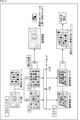
例えば、図1の例のように、プロジェクタ11から所定の絵柄の標準化光パタン12をスクリーン13に投影し、カメラ14によりその投影された標準化光パタン12を撮像して撮像画像15を得る。そして、その標準化光パタン12の絵柄に基づいて標準化光パタン12と撮像画像15との対応点を求め、その対応点に基づいて三角測量等によりプロジェクタ11とカメラ14の姿勢(位置関係)やスクリーン13の形状等を求め、その結果に基づいて幾何補正を行う方法がある。
For example, as in the example of FIG. 1, a standardized
このようにカメラを利用して幾何補正を行う場合、投影画像(投影される画像でもよい)と撮像画像との間で対応点(投影画像および撮像画像の、投影面の互いに同じ位置に対応する画素)を求める必要がある。つまり、カメラ14(撮像画像15)の画素とプロジェクタ11(標準化光パタン12)の画素との対応関係を求める必要がある。この対応点検出処理は、一般的にStructured Light(構造化光)と呼ばれる。 When geometric correction is performed using a camera in this way, a corresponding point (the projected image and the captured image correspond to the same position on the projection surface) between the projected image (which may be the projected image) and the captured image. It is necessary to obtain the pixel). That is, it is necessary to find the correspondence between the pixels of the camera 14 (captured image 15) and the pixels of the projector 11 (standardized optical pattern 12). This corresponding point detection process is generally called Structured Light.
GrayCodeやDotおよびCheckerなどのパタン画像をプロジェクタで投影し、それをカメラで撮像して対応点検出する方法をオフラインセンシングと呼ぶことにする。外乱を検知後にオフラインセンシングによってプロジェクタの姿勢を推定する場合は、いったん映像コンテンツの投影をやめてパタン画像を投影する事になるため、映像視聴の中断が必須となり、快適な視聴体験を提供するのは困難である。 The method of projecting a pattern image such as Gray Code, Dot, and Checker with a projector, capturing it with a camera, and detecting the corresponding point is called offline sensing. When estimating the posture of the projector by offline sensing after detecting a disturbance, the projection of the video content is temporarily stopped and the pattern image is projected, so it is essential to interrupt the video viewing, and it is necessary to provide a comfortable viewing experience. Have difficulty.
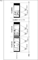
一方で動画投影中に対応点を検出して、プロジェクタとカメラの姿勢を推定する方法をオンラインセンシングと呼ぶことにする。オンラインセンシングでの対応点検出には、動画像内に人間の目では知覚されないパタンを重畳して対応点検出を行うImperceptible Structured Light(図2)や動画像内の特徴点を検出して特徴点同士の対応付けを行う方法(図3)などが挙げられる。 On the other hand, the method of estimating the posture of the projector and the camera by detecting the corresponding point during video projection is called online sensing. Corresponding points can be detected by online sensing using Imperceptible Structured Light (Fig. 2), which detects corresponding points by superimposing patterns that are not perceived by the human eye on moving images, and feature points by detecting feature points in moving images. Examples thereof include a method of associating with each other (Fig. 3).
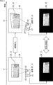
ISL方式は、所定のパタンの画像である構造化光パタンをポジ・ネガ反転させて投影画に埋め込み、人間に知覚されないように投影する技術である。 The ISL method is a technology in which a structured optical pattern, which is an image of a predetermined pattern, is inverted positively and negatively, embedded in a projection image, and projected so as not to be perceived by humans.
図2に示されるように、プロジェクタは、入力画像のあるフレームに対して所定の構造化光パタンを足すことにより、入力画像に構造化光パタンのポジ画像を合成したフレーム画像を生成し、入力画像のその次のフレームに対して構造化光パタンを引くことにより、入力画像に構造化光パタンのネガ画像を合成したフレーム画像を生成する。そしてプロジェクタは、それらのフレームを連続投影する。高速に切り替えられたポジ・ネガの2フレームは、積分効果により人間の目には足し合わされて知覚される。その結果、投影画像を視るユーザにとって、入力画像に埋め込まれた構造化光パタンを認識することが困難になる。 As shown in FIG. 2, the projector adds a predetermined structured optical pattern to a frame having an input image to generate a frame image in which a positive image of the structured optical pattern is combined with the input image and inputs the input image. By drawing a structured optical pattern for the next frame of the image, a frame image is generated in which the negative image of the structured optical pattern is combined with the input image. The projector then continuously projects those frames. The two frames of positive and negative that are switched at high speed are added and perceived by the human eye due to the integral effect. As a result, it becomes difficult for the user who views the projected image to recognize the structured optical pattern embedded in the input image.
これに対して、カメラは、それらのフレームの投影画像を撮像し、両フレームの撮像画像の差分を求めることにより、撮像画像に含まれる構造化光パタンのみを抽出する。この抽出された構造化光パタンを用いて対応点検出が行われる。 On the other hand, the camera captures the projected images of those frames and obtains the difference between the captured images of both frames to extract only the structured optical pattern contained in the captured images. Corresponding point detection is performed using this extracted structured optical pattern.
このように、ISL方式では撮像画像の差分を求めるだけで容易に構造化パタンを抽出することができるので、投影する画像に依存せずに安定した精度で対応点検出を行うことができる。 In this way, in the ISL method, the structured pattern can be easily extracted only by obtaining the difference between the captured images, so that the corresponding points can be detected with stable accuracy without depending on the projected image.
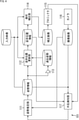
図3に示されるように、動画像の中の特徴点を検出し、特徴点同士の対応付けを行う方法もある。時刻t1において、投影撮像装置21のプロジェクタ(投影部)22とカメラ(撮像部)23は、姿勢RT_t1である。このとき、プロジェクタ22は、スクリーン24に投影画像25_t1を投影し、カメラ23は、投影画像25_t1を撮像し、撮像画像26_t1を生成する。
As shown in FIG. 3, there is also a method of detecting feature points in a moving image and associating the feature points with each other. At time t1, the projector (projection unit) 22 and the camera (imaging unit) 23 of the projection
その後、時刻t2において、投影撮像装置21のプロジェクタ(投影部)22とカメラ(撮像部)23の姿勢変化があり、投影撮像装置21のプロジェクタ(投影部)22とカメラ(撮像部)23は、姿勢RT_t2である。このとき、プロジェクタ22は、スクリーン24に投影画像25_t2を投影し、カメラ23は、投影画像25_t2を撮像し、撮像画像26_t2を生成する。
After that, at time t2, the postures of the projector (projection unit) 22 and the camera (imaging unit) 23 of the
このように、入力映像を投影している最中に、生成された時刻t1での撮像画像26_t1と、時刻t2での撮像画像26_t2において対応点が検出されるので、外乱によってプロジェクタの姿勢が変化しても自動的に正しい映像呈示位置に更新できる利点がある。(前述のパタン画像を投影する必要はない)。 In this way, while the input image is being projected, the corresponding points are detected in the captured image 26_t1 at the generated time t1 and the captured image 26_t2 at the time t2, so that the attitude of the projector changes due to disturbance. However, there is an advantage that it can be automatically updated to the correct image presentation position. (It is not necessary to project the pattern image mentioned above).
しかしながら、映像を呈示したまま、プロジェクタの姿勢を推定し、映像の呈示位置を更新するので、プロジェクタの姿勢およびスクリーンの形状の推定(以下、センシングとも称する)前後で映像呈示位置が大きく変わる場合など、快適な視聴体験とは言い難く、広視野映像を大画面スクリーンに投影しているときは、映像酔いを引き起こしてしまう恐れがあった。 However, since the posture of the projector is estimated and the presentation position of the image is updated while the image is being presented, the image presentation position may change significantly before and after estimating the posture of the projector and the shape of the screen (hereinafter, also referred to as sensing). It is hard to say that it is a comfortable viewing experience, and when a wide-field image is projected on a large screen, there is a risk of causing image sickness.
そこで、本技術においては、センシング前後の映像呈示位置の急激な変化を抑えたり、映像呈示のタイミングを制御したりする。これにより、快適な視聴体験を提供することができる。 Therefore, in the present technology, abrupt changes in the image presentation position before and after sensing are suppressed, and the timing of image presentation is controlled. This makes it possible to provide a comfortable viewing experience.
<投影撮像装置の構成例>
図4は、本技術を適用した投影撮像装置の構成例を示すブロック図である。<Configuration example of projection imaging device>
FIG. 4 is a block diagram showing a configuration example of a projection imaging device to which the present technology is applied.
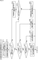
図4の例において、投影撮像装置101は、姿勢推定部111、呈示位置更新部112、遅延部113、幾何補正部114、プロジェクタ115、カメラ116、および外乱検知部117を含むように構成されている。入力映像は、呈示位置更新部112、幾何補正部114、および外乱検知部117に入力される。
In the example of FIG. 4, the
姿勢推定部111は、プロジェクタ115の初期姿勢とスクリーンの形状を推定する。なお、推定方法は、オフラインセンシング(パターン投影)であってもよいし、オンラインセンシングであってもよい。姿勢推定部111は、推定したプロジェクタ115の姿勢情報とスクリーンの形状情報を、呈示位置更新部112、遅延部113、外乱検知部117に供給する。
The
呈示位置更新部112には、入力映像、プロジェクタ115の姿勢情報とスクリーンの形状情報、および遅延部113からの過去姿勢情報が入力される。呈示位置更新部112は、例えば、プロジェクタ115の姿勢情報とスクリーンの形状情報から初期映像呈示位置を求め、その情報である呈示位置情報を、幾何補正部114に供給する。
The input image, the posture information of the
幾何補正部114は、入力映像が初期映像呈示位置に投影されるように、入力映像を補正し、補正画像を生成して、プロジェクタ115に出力する。プロジェクタ115は、補正画像を、スクリーンに投影する。
The
カメラ116は、プロジェクタ115からスクリーンに投影されている投影画像を撮像し、撮像画像を生成して、外乱検知部117および姿勢推定部111に供給する。
The
なお、プロジェクタ115も、カメラ116も複数台であってもよい。また、プロジェクタ115に対して、カメラ116が1台であってもよいし、複数のプロジェクタ115に対して、カメラ116が1台であってもよいし、複数のカメラ116に対して、プロジェクタ115が1台であってもよい。
The
外乱検知部117は、カメラ116からの撮像画像を用いて、外乱を検知する。外乱検知部117は、姿勢情報と呈示位置情報から、入力映像が投影される領域(マスク画像)を計算する。
The
例えば、プロジェクタ115-0とプロジェクタ115-1で投影しており、それぞれに対応して、カメラ116-0とカメラ116-1が投影画像を撮像している場合を考える。この場合、図5に示されるように、呈示位置情報のうち、プロジェクタ画隅呈示位置情報から、プロジェクタ115-0の投影領域(pro0投影領域)とプロジェクタ115-1の投影領域(pro1投影領域)が求められ、プロジェクタ115-0および115-1それぞれの姿勢情報から、mask領域(投影領域)が示されるカメラ116-0のマスク画像121-0とカメラ116-1のマスク画像121-1が求められる。 For example, consider a case where the projector 115-0 and the projector 115-1 are projecting, and the camera 116-0 and the camera 116-1 are capturing the projected image corresponding to each. In this case, as shown in FIG. 5, among the presentation position information, from the projector image corner presentation position information, the projection area of the projector 115-0 (pro0 projection area) and the projection area of the projector 115-1 (pro1 projection area). Is obtained, and the mask image 121-0 of the camera 116-0 and the mask image 121-1 of the camera 116-1 showing the mask area (projection area) are obtained from the attitude information of each of the projectors 115-0 and 115-1. Be done.
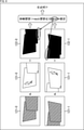
次に、外乱検知部117は、図6に示されるように、マスク画像121-0と撮像画像131-0をマスク処理して、マスク処理画像132-0を生成し、マスク処理画像132-0の背景領域(mask領域外)に変化があるかどうかを調べる。同様に、外乱検知部117は、マスク画像121-1と撮像画像131-1をマスク処理して、マスク処理画像132-1を生成し、マスク処理画像132-1の背景領域(mask領域外)に変化があるかどうかを調べる。
Next, as shown in FIG. 6, the
図6の例の場合、マスク処理画像132-0の背景領域の右下部分に変化があるので、外乱があると判定され、マスク処理画像132-1の背景領域の左上部分に変化があるので、外乱があると判定される。 In the case of the example of FIG. 6, since there is a change in the lower right part of the background area of the masked image 132-0, it is determined that there is a disturbance, and there is a change in the upper left part of the background area of the masked image 132-1. , It is determined that there is a disturbance.
また、外乱がなければ、スクリーンの投影画像の背景領域にプロジェクタの光(入力映像)は当たらないので、変化がない。これに対して、外乱が発生すると、スクリーンの投影画像の背景領域にプロジェクタの光が当たるので、外乱検知部117はそれを検知する。
Further, if there is no disturbance, the light (input image) of the projector does not hit the background area of the projected image on the screen, so that there is no change. On the other hand, when a disturbance occurs, the light of the projector hits the background area of the projected image on the screen, and the
すなわち、図7の例においては、外乱発生前のスクリーン151の投影画像の背景領域にプロジェクタ115-0および115-1の光(入力映像)は当たっていないが、外乱発生後のスクリーン151の投影画像の背景領域にプロジェクタ115-1の光が当たっている。外乱検知部117はこの外乱を検知し、センシングすることで、外乱復帰後のスクリーン151に、外乱が起こっていない投影画像を投影することができる。
That is, in the example of FIG. 7, the light (input image) of the projectors 115-0 and 115-1 does not hit the background area of the projected image of the screen 151 before the disturbance occurs, but the projection of the screen 151 after the disturbance occurs. The light of the projector 115-1 is shining on the background area of the image. By detecting and sensing this disturbance, the
以降、外乱検知後の呈示位置更新部112の動作について説明する。
Hereinafter, the operation of the presentation
外乱検知部117は、外乱の検知を姿勢推定部111に通知する。姿勢推定部111は、外乱が検知されたら、プロジェクタの姿勢およびスクリーンの形状を推定し、姿勢情報とスクリーン形状情報を、呈示位置更新部112に供給する。
The
呈示位置更新部112は、外乱発生前の姿勢情報(過去姿勢情報)と外乱発生後の姿勢情報とを比較して、幾何補正部114へ渡す呈示位置情報を決定する。例えば、呈示位置更新部112は、複数のプロジェクタを用いて入力映像をスクリーンに呈示している場合は、外乱が発生したプロジェクタ(すなわち、姿勢が変化したプロジェクタ)だけ映像呈示位置を更新する。つまり、外乱が発生していないプロジェクタは、映像呈示位置が維持される。
The presentation
また、呈示位置更新部112は、多数のプロジェクタに外乱があり、映像呈示位置を維持するのが困難な場合、入力映像のシーンチェンジのタイミングで呈示位置を更新する。他にも、呈示位置の更新前後にエフェクト(フェードアウト=>フェードインなど)をかけることで、呈示位置の急激な変化を抑えることができる。その際、変化の度合いを判定し、変化の度合いに応じたエフェクトをかけるようにしてもよい。さらに、ユーザに呈示位置の更新タイミングを事前に通知するようにしてもよい。
Further, when it is difficult to maintain the image presentation position due to disturbance in a large number of projectors, the presentation
次に、図8のフローチャートを参照して、投影撮像装置101の投影撮像処理について説明する。
Next, the projection imaging process of the
ステップS101において、姿勢推定部111は、プロジェクタ115の初期姿勢とスクリーンの形状を推定する。姿勢推定部111は、推定したプロジェクタ115の姿勢情報とスクリーンの形状情報を、呈示位置更新部112、遅延部113、外乱検知部117に供給する。
In step S101, the
呈示位置更新部112には、入力映像、プロジェクタ115の姿勢情報とスクリーンの形状情報、および遅延部113からの過去姿勢情報が入力される。ステップS102において、呈示位置更新部112は、プロジェクタ115の姿勢情報とスクリーンの形状情報から初期映像呈示位置を求め、その情報である呈示位置情報を、幾何補正部114に供給する。
The input image, the posture information of the
ステップS103において、幾何補正部114は、入力映像が初期映像呈示位置に投影されるように、入力映像を補正し、補正画像を生成して、プロジェクタ115に出力する。プロジェクタ115は、ステップS104において、補正画像を、スクリーンに投影する。
In step S103, the
ステップS105において、カメラ116は、プロジェクタ115からスクリーンに投影されている投影画像を撮像し、撮像画像を生成して、外乱検知部117および姿勢推定部111に供給する。
In step S105, the
ステップS106において、外乱検知部117は、図5乃至図7を参照して上述したように外乱の発生を検知することで、プロジェクタの姿勢が変化したか否かを判定する。
In step S106, the
ステップS106において、プロジェクタ115の姿勢が変化していないと判定された場合、処理は、ステップS101に戻り、それ以降の処理が繰り返される。ステップS106において、プロジェクタ115の姿勢が変化したと判定された場合、処理は、ステップS107に進む。
If it is determined in step S106 that the posture of the
ステップS107において、投影撮像装置101は、外乱発生後処理を行う。この外乱発生処理の詳細は、図9を参照して後述される。ステップS107における外乱発生後処理の後、処理は、ステップS103に戻り、それ以降の処理が繰り返される。
In step S107, the
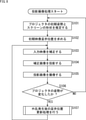
次に、図9のフローチャートを参照して、図8のステップS107の外乱発生後の呈示位置更新処理について説明する。 Next, the presentation position update process after the occurrence of the disturbance in step S107 of FIG. 8 will be described with reference to the flowchart of FIG.
外乱検知部117は、外乱の検知を姿勢推定部111に通知する。姿勢推定部111は、外乱が検知されたら、ステップS111において、プロジェクタの姿勢およびスクリーンの形状を推定し、姿勢情報とスクリーン形状情報を、呈示位置更新部112に供給する。
The
ステップS112において、呈示位置更新部112は、外乱発生前の姿勢情報(過去姿勢情報)と外乱発生後の姿勢情報とを比較する。
In step S112, the presentation
ステップS113において、呈示位置更新部112は、多数のプロジェクタの姿勢が変化したか否かを判定する。ステップS113において、多数のプロジェクタの姿勢が変化していないと判定された場合、処理は、ステップS114に進む。なお、ステップS113においては、多数のプロジェクタを判定するようにした。その際、閾値を設けて、閾値以上を多数として判定してもよいし、単数かまたは複数かを判定するようにしてもよい。
In step S113, the presentation
ステップS114において、呈示位置更新部112は、外乱前後の呈示位置の変化を比較し、処理は、ステップS115に進む。ステップS115において、呈示位置更新部112は、外乱前後の呈示位置の変化が大きいか否かを判定する。ステップS115において、変化が大きいと判定された場合、処理は、ステップS116に進む。
In step S114, the presentation
一方、ステップS113において、多数のプロジェクタの姿勢が変化したと判定された場合も、処理は、ステップS116に進む。ステップS116において、呈示位置更新部112は、入力映像にシーンチェンジが存在するか否かを判定する。ステップS116において、入力映像にシーンチェンジが存在すると判定された場合、処理は、ステップS117に進む。
On the other hand, even if it is determined in step S113 that the postures of a large number of projectors have changed, the process proceeds to step S116. In step S116, the presentation
ステップS117において、呈示位置更新部112は、呈示位置変化が大きいか否かを判定する。ステップS117において、呈示位置変化が大きいと判定された場合、処理は、ステップS118に進む。ステップS118において、呈示位置更新部112は、シーンチェンジ前後にエフェクトをかけながら呈示位置更新を行う。更新後、呈示位置更新処理は終了し、処理は、図8のステップS107に戻る。
In step S117, the presentation
ステップS117において、呈示位置変化が小さいと判定された場合、処理は、ステップS119に進む。ステップS119において、呈示位置更新部112は、シーンチェンジで呈示位置更新を行う。更新後、呈示位置更新処理は終了し、処理は、図8のステップS107に戻る。
If it is determined in step S117 that the change in the presentation position is small, the process proceeds to step S119. In step S119, the presentation
ステップS116において、入力映像にシーンチェンジが存在しないと判定された場合、処理は、ステップS120に進む。ステップS120において、呈示位置更新部112は、プロジェクタ115やユーザに事前に更新を通知する。通知後は、図示されていないが、例えば、ユーザによる了解を得られた後に、必要に応じて、呈示位置更新処理を行う。更新後、呈示位置更新処理は終了し、処理は、図8のステップS107に戻る。
If it is determined in step S116 that there is no scene change in the input video, the process proceeds to step S120. In step S120, the presentation
また、ステップS115において、変化が小さいと判定された場合、処理は、ステップS121に進む。ステップS121において、呈示位置更新部112は、姿勢変化があるプロジェクタ115のみの呈示位置更新処理を行う。更新後、呈示位置更新処理は終了し、処理は、図8のステップS107に戻る。
If it is determined in step S115 that the change is small, the process proceeds to step S121. In step S121, the presentation
以上のように、本技術によれば、映像コンテンツをスクリーンに投影している最中に外乱によってプロジェクタの姿勢がずれて映像に歪みが生じても、(パタン投影を必要とすることなく)自動的に歪みのない映像をスクリーン面に投影でき、かつ、快適な視聴体験を提供することができる。 As described above, according to this technology, even if the posture of the projector shifts due to disturbance while the video content is projected on the screen and the image is distorted, it is automatically (without requiring pattern projection). It is possible to project a distortion-free image on the screen surface and provide a comfortable viewing experience.
特に大画面スクリーンや広視野スクリーンなどを使った映像視聴では、映像呈示位置の急激な変化が映像酔いを引き起こす恐れがあるが、それに対しての本技術の効果は大きいと予測される。 Especially in video viewing using a large screen or a wide-field screen, a sudden change in the video presentation position may cause video sickness, but the effect of this technology is expected to be great.
なお、上記説明においては、カメラを利用した外乱検知を行う例を説明したが、カメラ以外のセンサ(例えば、加速度センサや温度センサ)を利用したり、センサフュージョンによる外乱検知を用いる場合にも、本技術は適用することができる。 In the above description, an example of performing disturbance detection using a camera has been described, but it is also possible to use a sensor other than the camera (for example, an acceleration sensor or a temperature sensor) or to use disturbance detection by sensor fusion. This technology can be applied.
<パーソナルコンピュータ>
上述した一連の処理は、ハードウエアにより実行することもできるし、ソフトウエアにより実行することもできる。一連の処理をソフトウエアにより実行する場合には、そのソフトウエアを構成するプログラムが、コンピュータにインストールされる。ここで、コンピュータには、専用のハードウエアに組み込まれているコンピュータや、各種のプログラムをインストールすることで、各種の機能を実行することが可能な汎用のパーソナルコンピュータなどが含まれる。<Personal computer>
The series of processes described above can be executed by hardware or software. When a series of processes are executed by software, the programs constituting the software are installed in the computer. Here, the computer includes a computer embedded in dedicated hardware, a general-purpose personal computer capable of executing various functions by installing various programs, and the like.
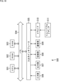
図10は、上述した一連の処理をプログラムにより実行するパーソナルコンピュータのハードウエアの構成例を示すブロック図である。 FIG. 10 is a block diagram showing a configuration example of hardware of a personal computer that executes the above-mentioned series of processes by a program.
パーソナルコンピュータ500において、CPU(Central Processing Unit)501,ROM(Read Only Memory)502,RAM(Random Access Memory)503は、バス504により相互に接続されている。
In the
バス504には、さらに、入出力インタフェース505が接続されている。入出力インタフェース505には、入力部506、出力部507、記憶部508、通信部509、及びドライブ510が接続されている。
An input /
入力部506は、キーボード、マウス、マイクロホンなどよりなる。出力部507は、ディスプレイ、スピーカなどよりなる。記憶部508は、ハードディスクや不揮発性のメモリなどよりなる。通信部509は、ネットワークインタフェースなどよりなる。ドライブ510は、磁気ディスク、光ディスク、光磁気ディスク、又は半導体メモリなどのリムーバブルメディア511を駆動する。
The
以上のように構成されるパーソナルコンピュータ500では、CPU501が、例えば、記憶部508に記憶されているプログラムを、入出力インタフェース505及びバス504を介して、RAM503にロードして実行する。これにより、上述した一連の処理が行われる。
In the
コンピュータ(CPU501)が実行するプログラムは、リムーバブルメディア511に記録して提供することができる。リムーバブルメディア511は、例えば、磁気ディスク(フレキシブルディスクを含む)、光ディスク(CD-ROM(Compact Disc-Read Only Memory),DVD(Digital Versatile Disc)等)、光磁気ディスク、もしくは半導体メモリなどよりなるパッケージメディア等である。また、あるいは、プログラムは、ローカルエリアネットワーク、インターネット、デジタル衛星放送といった、有線または無線の伝送媒体を介して提供することができる。
The program executed by the computer (CPU 501) can be recorded and provided on the
コンピュータにおいて、プログラムは、リムーバブルメディア511をドライブ510に装着することにより、入出力インタフェース505を介して、記憶部508にインストールすることができる。また、プログラムは、有線または無線の伝送媒体を介して、通信部509で受信し、記憶部508にインストールすることができる。その他、プログラムは、ROM502や記憶部508に、あらかじめインストールしておくことができる。
In the computer, the program can be installed in the
なお、コンピュータが実行するプログラムは、本明細書で説明する順序に沿って時系列に処理が行われるプログラムであっても良いし、並列に、あるいは呼び出しが行われたとき等の必要な段階で処理が行われるプログラムであっても良い。 The program executed by the computer may be a program in which processing is performed in chronological order according to the order described in this specification, or at a necessary stage such as in parallel or when a call is made. It may be a program in which processing is performed.
また、本明細書において、記録媒体に記録されるプログラムを記述するステップは、記載された順序に沿って時系列的に行われる処理はもちろん、必ずしも時系列的に処理されなくとも、並列的あるいは個別に実行される処理をも含むものである。 Further, in the present specification, the steps for describing a program to be recorded on a recording medium are not only processed in chronological order in the order described, but also in parallel or not necessarily in chronological order. It also includes processes that are executed individually.
また、本明細書において、システムとは、複数のデバイス(装置)により構成される装置全体を表すものである。 Further, in the present specification, the system represents an entire device composed of a plurality of devices (devices).
例えば、本開示は、1つの機能を、ネットワークを介して複数の装置で分担、共同して処理するクラウドコンピューティングの構成をとることができる。 For example, the present disclosure can be configured as cloud computing in which one function is shared and jointly processed by a plurality of devices via a network.
また、以上において、1つの装置(または処理部)として説明した構成を分割し、複数の装置(または処理部)として構成するようにしてもよい。逆に、以上において複数の装置(または処理部)として説明した構成をまとめて1つの装置(または処理部)として構成されるようにしてもよい。また、各装置(または各処理部)の構成に上述した以外の構成を付加するようにしてももちろんよい。さらに、システム全体としての構成や動作が実質的に同じであれば、ある装置(または処理部)の構成の一部を他の装置(または他の処理部)の構成に含めるようにしてもよい。つまり、本技術は、上述した実施の形態に限定されるものではなく、本技術の要旨を逸脱しない範囲において種々の変更が可能である。 Further, in the above, the configuration described as one device (or processing unit) may be divided and configured as a plurality of devices (or processing units). On the contrary, the configurations described above as a plurality of devices (or processing units) may be collectively configured as one device (or processing unit). Further, of course, a configuration other than the above may be added to the configuration of each device (or each processing unit). Further, if the configuration and operation of the entire system are substantially the same, a part of the configuration of one device (or processing unit) may be included in the configuration of another device (or other processing unit). .. That is, the present technology is not limited to the above-described embodiment, and various changes can be made without departing from the gist of the present technology.
以上、添付図面を参照しながら本開示の好適な実施形態について詳細に説明したが、本開示はかかる例に限定されない。本開示の属する技術の分野における通常の知識を有する者であれば、請求の範囲に記載された技術的思想の範疇内において、各種の変更例または修正例に想到し得ることは明らかであり、これらについても、当然に本開示の技術的範囲に属するものと了解される。 Although the preferred embodiments of the present disclosure have been described in detail with reference to the accompanying drawings, the present disclosure is not limited to such examples. It is clear that anyone with ordinary knowledge in the field of technology to which this disclosure belongs can come up with various modifications or modifications within the scope of the technical ideas set forth in the claims. These are, of course, understood to belong to the technical scope of the present disclosure.
なお、本技術は以下のような構成も取ることができる。
(1) プロジェクタから投影される投影画像を撮像して生成された撮像画像を用いて、前記プロジェクタの外乱を検知する外乱検知部と、
前記外乱検知部により外乱が検知された場合、外乱検知前後の姿勢情報を比較し、前記外乱検知前後の姿勢情報に変化があるプロジェクタのみ、呈示位置の更新を行う呈示位置更新部と
を備える画像処理装置。
(2) 前記プロジェクタから投影される前記投影画像を撮像し、前記撮像画像を生成する撮像部を
さらに備える前記(1)に記載の画像処理装置。
(3) 前記呈示位置更新部は、複数のプロジェクタの姿勢情報に変化がなく、外乱検知前後の呈示位置の変化が小さい場合に、前記外乱検知前後の姿勢情報に変化があるプロジェクタのみ、呈示位置の更新を行う
前記(1)に記載の画像処理装置。
(4) 入力映像にシーンチェンジがあるか否かを判定するシーンチェンジ判定部
をさらに備え、
前記シーンチェンジ判定部によりシーンチェンジがあると判定された場合、前記呈示位置更新部は、前記シーンチェンジ周辺で、呈示位置の更新を行う
前記(1)乃至(3)のいずれかに記載の画像処理装置。
(5) 前記シーンチェンジ判定部は、複数のプロジェクタの姿勢情報に変化がある場合、または、複数のプロジェクタの姿勢情報に変化がないが、外乱検知前後の呈示位置の変化が大きい場合に、入力映像にシーンチェンジがあるか否かを判定する
前記(4)に記載の画像処理装置。
(6) 前記シーンチェンジ判定部によりシーンチェンジがあると判定された場合、外乱検知前後の呈示位置変化が大きいか否かを判定する呈示位置変化判定部を
さらに備え、
前記呈示位置変化判定部により外乱検知前後の呈示位置変化が大きいと判定された場合、前記呈示位置更新部は、前記シーンチェンジ前後にエフェクトをかけながら呈示位置の更新を行う
前記(4)に記載の画像処理装置。
(7) 前記呈示位置変化判定部により外乱検知前後の呈示位置変化が小さいと判定された場合、前記呈示位置更新部は、前記シーンチェンジで呈示位置の更新を行う
前記(6)に記載の画像処理装置。
(8) 前記シーンチェンジ判定部によりシーンチェンジがないと判定された場合、前記呈示位置更新部は、ユーザに事前に通知を行ってから、呈示位置の更新を行う
前記(3)に記載の画像処理装置。
(9) 前記呈示位置更新部は、エフェクトをかけながら、呈示位置の更新を行う
前記(1)に記載の画像処理装置。
(10) 外乱検知後の呈示位置変化の度合いを判定する呈示位置変化判定部を
さらに備え、
前記呈示位置更新部は、呈示位置変化の度合いに応じて、エフェクトをかけながら、呈示位置の更新を行う
前記(9)に記載の画像処理装置。
(11) 前記プロジェクタの外乱は、プロジェクタの配置変更、プロジェクタの数の増減、プロジェクタへの物理的接触による姿勢ずれ、または、温度特性や経時変化による姿勢ずれである
前記(1)乃至(10)のいずれかに記載の画像処理装置。
(12) 画像処理装置が、
プロジェクタから投影される投影画像を撮像して生成された撮像画像を用いて、前記プロジェクタの外乱を検知し、
前記外乱が検知された場合、外乱検知前後の姿勢情報を比較し、前記外乱検知前後の姿勢情報に変化があるプロジェクタのみ、呈示位置の更新を行う
画像処理方法。
(13) プロジェクタから投影される投影画像を撮像して生成された撮像画像を用いて、前記プロジェクタの外乱を検知する外乱検知部と、
前記外乱検知部により外乱が検知された場合、外乱検知前後の姿勢情報を比較し、前記外乱検知前後の姿勢情報に変化があるプロジェクタのみ、呈示位置の更新を行う呈示位置更新部と
して、コンピュータを機能させるプログラム。The present technology can also have the following configurations.
(1) A disturbance detection unit that detects the disturbance of the projector by using the captured image generated by capturing the projected image projected from the projector, and
When a disturbance is detected by the disturbance detection unit, an image provided with a presentation position update unit that compares the attitude information before and after the disturbance detection and updates the presentation position only for a projector whose attitude information before and after the disturbance detection changes. Processing equipment.
(2) The image processing apparatus according to (1), further comprising an imaging unit that captures the projected image projected from the projector and generates the captured image.
(3) The presentation position update unit is only for projectors in which the posture information before and after the disturbance detection changes when the posture information of the plurality of projectors does not change and the change in the presentation position before and after the disturbance detection is small. The image processing apparatus according to (1) above.
(4) Further equipped with a scene change determination unit that determines whether or not there is a scene change in the input video.
When the scene change determination unit determines that there is a scene change, the presentation position update unit updates the presentation position around the scene change. The image according to any one of (1) to (3). Processing device.
(5) The scene change determination unit inputs when there is a change in the attitude information of a plurality of projectors, or when there is no change in the attitude information of a plurality of projectors but the change in the presentation position before and after the disturbance detection is large. The image processing device according to (4) above, which determines whether or not there is a scene change in the image.
(6) When it is determined by the scene change determination unit that there is a scene change, a presentation position change determination unit for determining whether or not the presentation position change before and after the disturbance detection is large is further provided.
When the presentation position change determination unit determines that the presentation position change before and after the disturbance detection is large, the presentation position update unit updates the presentation position while applying an effect before and after the scene change. Image processing equipment.
(7) The image according to (6) above, when the presentation position change determination unit determines that the presentation position change before and after the disturbance detection is small, the presentation position update unit updates the presentation position by the scene change. Processing device.
(8) When the scene change determination unit determines that there is no scene change, the presentation position update unit notifies the user in advance and then updates the presentation position. The image according to (3) above. Processing device.
(9) The image processing apparatus according to (1) above, wherein the presentation position updating unit updates the presentation position while applying an effect.
(10) Further equipped with a presentation position change determination unit for determining the degree of presentation position change after disturbance detection is provided.
The image processing apparatus according to (9) above, wherein the presentation position updating unit updates the presentation position while applying an effect according to the degree of change in the presentation position.
(11) The disturbance of the projector is a change in the arrangement of the projectors, an increase or decrease in the number of projectors, a posture shift due to physical contact with the projector, or a posture shift due to temperature characteristics or changes over time (1) to (10). The image processing apparatus according to any one of.
(12) The image processing device
Using the captured image generated by capturing the projected image projected from the projector, the disturbance of the projector is detected.
An image processing method in which when the disturbance is detected, the posture information before and after the disturbance detection is compared, and the presentation position is updated only for the projector in which the posture information before and after the disturbance detection is changed.
(13) A disturbance detection unit that detects the disturbance of the projector by using the captured image generated by capturing the projected image projected from the projector, and
When a disturbance is detected by the disturbance detection unit, the presentation position update unit is used to compare the attitude information before and after the disturbance detection and update the presentation position only for the projector whose attitude information before and after the disturbance detection changes. A program that makes a computer work.
101 投影撮像装置, 111 姿勢推定部, 112 呈示位置更新部, 113 遅延部, 114 幾何補正部, 115,115-0,115-1 プロジェクタ, 116,116-0,116-1 カメラ, 117 外乱検知部, 151 スクリーン 101 Projection imager, 111 Posture estimation unit, 112 Presentation position update unit, 113 Delay unit, 114 Geometry correction unit, 115, 115-0, 115-1 projector, 116, 116-0, 116-1 camera, 117 Disturbance detection Department, 151 screen
Claims (7)
前記外乱検知部により外乱が検知された場合、外乱検知前後の姿勢情報を比較し、前記外乱検知前後の姿勢情報に変化があるプロジェクタのみ、前記投影画像に歪が出ない位置に呈示位置の更新を行う呈示位置更新部と、
入力映像にシーンチェンジがあるか否かを判定するシーンチェンジ判定部と
を備え、
前記シーンチェンジ判定部によりシーンチェンジがあると判定された場合、前記呈示位置更新部は、前記外乱検知前後の姿勢情報に変化があるプロジェクタのみ、シーンチェンジ周辺で、前記呈示位置の更新を行い、
前記シーンチェンジ判定部によりシーンチェンジがないと判定された場合、前記呈示位置更新部は、前記外乱検知前後の姿勢情報に変化があるプロジェクタのみ、ユーザに事前に通知を行ってから、前記呈示位置の更新を行う
画像処理装置。 A disturbance detection unit that detects the disturbance of the projector using the captured image generated by capturing the projected image projected from the projector, and
When a disturbance is detected by the disturbance detection unit, the attitude information before and after the disturbance detection is compared, and only the projector whose attitude information before and after the disturbance detection changes is updated to the position where the projected image is not distorted. Presentation position update section and
With the scene change judgment unit that determines whether or not there is a scene change in the input video
Equipped with
When it is determined by the scene change determination unit that there is a scene change, the presentation position update unit updates the presentation position around the scene change only for the projector whose posture information changes before and after the disturbance detection.
When the scene change determination unit determines that there is no scene change, the presentation position update unit notifies the user in advance only for the projector whose posture information changes before and after the disturbance detection, and then the presentation position. Update
Image processing device.
さらに備える請求項1に記載の画像処理装置。 The image processing apparatus according to claim 1, further comprising an imaging unit that captures the projected image projected from the projector and generates the captured image.
請求項1に記載の画像処理装置。 When the scene change determination unit determines that there is a scene change, the presentation position update unit updates the presentation position while applying an effect before and after the scene change.
The image processing apparatus according to claim 1 .
請求項1に記載の画像処理装置。 When the scene change determination unit determines that there is no scene change, the presentation position update unit updates the presentation position while applying an effect.
The image processing apparatus according to claim 1 .
さらに備え、
前記呈示位置更新部は、呈示位置変化の度合いに応じて、エフェクトをかけながら、または、エフェクトをかけないで、前記呈示位置の更新を行う
請求項1に記載の画像処理装置。 It also has a presentation position change determination unit that determines the degree of presentation position change after disturbance detection.
The presentation position update unit updates the presentation position with or without applying an effect , depending on the degree of change in the presentation position.
The image processing apparatus according to claim 1 .
請求項1に記載の画像処理装置。 The disturbance of the projector is a change in the arrangement of the projectors, an increase or decrease in the number of projectors, a posture shift due to physical contact with the projector, or a posture shift due to temperature characteristics or changes over time.
The image processing apparatus according to claim 1 .
プロジェクタから投影される投影画像を撮像して生成された撮像画像を用いて、前記プロジェクタの外乱を検知し、
前記外乱が検知された場合、外乱検知前後の姿勢情報を比較し、前記外乱検知前後の姿勢情報に変化があるプロジェクタのみ、前記投影画像に歪が出ない位置に呈示位置の更新を行い、
入力映像にシーンチェンジがあるか否かを判定し、
シーンチェンジがあると判定された場合、前記外乱検知前後の姿勢情報に変化があるプロジェクタのみ、シーンチェンジ周辺で、前記呈示位置の更新を行い、
シーンチェンジがないと判定された場合、前記外乱検知前後の姿勢情報に変化があるプロジェクタのみ、ユーザに事前に通知を行ってから、前記呈示位置の更新を行う
画像処理方法。 The image processing device
Using the captured image generated by capturing the projected image projected from the projector, the disturbance of the projector is detected.
When the disturbance is detected, the posture information before and after the disturbance detection is compared, and only the projector whose posture information before and after the disturbance detection changes is updated to the position where the projected image is not distorted .
Determine if there is a scene change in the input video,
When it is determined that there is a scene change, the presentation position is updated around the scene change only for the projector whose attitude information changes before and after the disturbance detection.
When it is determined that there is no scene change, only the projector whose attitude information changes before and after the disturbance detection is notified in advance to the user, and then the presentation position is updated.
Image processing method.
Applications Claiming Priority (3)
| Application Number | Priority Date | Filing Date | Title |
|---|---|---|---|
| JP2016064244 | 2016-03-28 | ||
| JP2016064244 | 2016-03-28 | ||
| PCT/JP2017/010110 WO2017169726A1 (en) | 2016-03-28 | 2017-03-14 | Image processing device and method |
Publications (2)
| Publication Number | Publication Date |
|---|---|
| JPWO2017169726A1 JPWO2017169726A1 (en) | 2019-02-07 |
| JP6996493B2 true JP6996493B2 (en) | 2022-01-17 |
Family
ID=59964344
Family Applications (1)
| Application Number | Title | Priority Date | Filing Date |
|---|---|---|---|
| JP2018508962A Active JP6996493B2 (en) | 2016-03-28 | 2017-03-14 | Image processing equipment and methods |
Country Status (3)
| Country | Link |
|---|---|
| US (1) | US10839553B2 (en) |
| JP (1) | JP6996493B2 (en) |
| WO (1) | WO2017169726A1 (en) |
Families Citing this family (2)
| Publication number | Priority date | Publication date | Assignee | Title |
|---|---|---|---|---|
| CN111629190A (en) * | 2019-02-28 | 2020-09-04 | 中强光电股份有限公司 | Projection system and projection method |
| JP7703907B2 (en) * | 2021-06-02 | 2025-07-08 | セイコーエプソン株式会社 | Projector and method for controlling the projector |
Citations (6)
| Publication number | Priority date | Publication date | Assignee | Title |
|---|---|---|---|---|
| JP2003259252A (en) | 2002-03-05 | 2003-09-12 | Sony Corp | Image processing apparatus, image processing method, and image processing program |
| JP2006197443A (en) | 2005-01-17 | 2006-07-27 | Seiko Epson Corp | Image processing system, projector, program, information storage medium, and image processing method |
| JP2008249906A (en) | 2007-03-29 | 2008-10-16 | Brother Ind Ltd | Projector and display system |
| JP2009224929A (en) | 2008-03-14 | 2009-10-01 | Seiko Epson Corp | Projection system |
| JP2012114863A (en) | 2010-11-26 | 2012-06-14 | Kyocera Corp | Portable electronic devices |
| JP2013195498A (en) | 2012-03-16 | 2013-09-30 | Nikon Corp | Multi-projector system |
Family Cites Families (3)
| Publication number | Priority date | Publication date | Assignee | Title |
|---|---|---|---|---|
| JP5121673B2 (en) | 2007-11-06 | 2013-01-16 | パナソニック株式会社 | Image projection apparatus and image projection method |
| WO2012070503A1 (en) | 2010-11-26 | 2012-05-31 | 京セラ株式会社 | Portable electronic apparatus |
| JP5906524B2 (en) * | 2013-04-24 | 2016-04-20 | 株式会社モルフォ | Image composition apparatus, image composition method, and program |
-
2017
- 2017-03-14 JP JP2018508962A patent/JP6996493B2/en active Active
- 2017-03-14 US US16/086,633 patent/US10839553B2/en active Active
- 2017-03-14 WO PCT/JP2017/010110 patent/WO2017169726A1/en not_active Ceased
Patent Citations (6)
| Publication number | Priority date | Publication date | Assignee | Title |
|---|---|---|---|---|
| JP2003259252A (en) | 2002-03-05 | 2003-09-12 | Sony Corp | Image processing apparatus, image processing method, and image processing program |
| JP2006197443A (en) | 2005-01-17 | 2006-07-27 | Seiko Epson Corp | Image processing system, projector, program, information storage medium, and image processing method |
| JP2008249906A (en) | 2007-03-29 | 2008-10-16 | Brother Ind Ltd | Projector and display system |
| JP2009224929A (en) | 2008-03-14 | 2009-10-01 | Seiko Epson Corp | Projection system |
| JP2012114863A (en) | 2010-11-26 | 2012-06-14 | Kyocera Corp | Portable electronic devices |
| JP2013195498A (en) | 2012-03-16 | 2013-09-30 | Nikon Corp | Multi-projector system |
Also Published As
| Publication number | Publication date |
|---|---|
| US20190102907A1 (en) | 2019-04-04 |
| WO2017169726A1 (en) | 2017-10-05 |
| JPWO2017169726A1 (en) | 2019-02-07 |
| US10839553B2 (en) | 2020-11-17 |
Similar Documents
| Publication | Publication Date | Title |
|---|---|---|
| US9191589B2 (en) | Image processing device | |
| US8274570B2 (en) | Image processing apparatus, image processing method, hand shake blur area estimation device, hand shake blur area estimation method, and program | |
| US20140176730A1 (en) | Projection-type image display device, image projection method, and computer program | |
| EP2858033A1 (en) | Method and device for correcting multi-exposure motion image | |
| JP2014150443A5 (en) | ||
| JP2013257686A5 (en) | ||
| KR20150011938A (en) | Method and apparatus for stabilizing panorama video captured based multi-camera platform | |
| US20150102998A1 (en) | Projection-type projector, anti-glare method, and program for anti-glare | |
| JP7001966B2 (en) | Image processing equipment and methods | |
| JP2019168862A5 (en) | ||
| JP6996493B2 (en) | Image processing equipment and methods | |
| JP2014127773A5 (en) | ||
| WO2018173797A1 (en) | Projector, projection method, image processing system, and method | |
| JP2010197541A (en) | Projector, image correction method, image correction apparatus, and projection system | |
| JP2016167681A (en) | Image generating apparatus and image generating method | |
| JP2011155477A (en) | Video processing apparatus, video processing method, and program | |
| JP2015037204A5 (en) | ||
| JPWO2018155269A1 (en) | Image processing apparatus and method, and program | |
| KR101219126B1 (en) | Control Method And System According to Image Motion Information Estimated with Image Characteristic | |
| WO2013088657A1 (en) | Projecting projector device, optical anti-glare method, and optical anti-glare program | |
| JP2013152537A (en) | Information processing apparatus and method, and program | |
| JP2021158393A (en) | Information processing device, information processing method, and program | |
| JP2012231406A (en) | Image processor and image processing method | |
| JP2016042639A (en) | Camera attitude control device, method and program | |
| JP2020109948A5 (en) |
Legal Events
| Date | Code | Title | Description |
|---|---|---|---|
| A621 | Written request for application examination |
Free format text: JAPANESE INTERMEDIATE CODE: A621 Effective date: 20200303 |
|
| A131 | Notification of reasons for refusal |
Free format text: JAPANESE INTERMEDIATE CODE: A131 Effective date: 20210608 |
|
| A521 | Request for written amendment filed |
Free format text: JAPANESE INTERMEDIATE CODE: A523 Effective date: 20210615 |
|
| TRDD | Decision of grant or rejection written | ||
| A01 | Written decision to grant a patent or to grant a registration (utility model) |
Free format text: JAPANESE INTERMEDIATE CODE: A01 Effective date: 20211116 |
|
| A61 | First payment of annual fees (during grant procedure) |
Free format text: JAPANESE INTERMEDIATE CODE: A61 Effective date: 20211129 |
|
| R151 | Written notification of patent or utility model registration |
Ref document number: 6996493 Country of ref document: JP Free format text: JAPANESE INTERMEDIATE CODE: R151 |