JP6996444B2 - Power converter and flicker detection method - Google Patents
Power converter and flicker detection method Download PDFInfo
- Publication number
- JP6996444B2 JP6996444B2 JP2018136674A JP2018136674A JP6996444B2 JP 6996444 B2 JP6996444 B2 JP 6996444B2 JP 2018136674 A JP2018136674 A JP 2018136674A JP 2018136674 A JP2018136674 A JP 2018136674A JP 6996444 B2 JP6996444 B2 JP 6996444B2
- Authority
- JP
- Japan
- Prior art keywords
- fluctuation
- power
- frequency deviation
- reactive power
- flicker
- Prior art date
- Legal status (The legal status is an assumption and is not a legal conclusion. Google has not performed a legal analysis and makes no representation as to the accuracy of the status listed.)
- Active
Links
Images


Landscapes
- Supply And Distribution Of Alternating Current (AREA)
Description
本発明は、電力変換装置及びフリッカ検出方法に関する。 The present invention relates to a power conversion device and a flicker detection method.
例えばパワーコンディショナ等の電力変換装置には、系統連系における単独運転検出機能が設けられる。単独運転検出機能の1つとして、電力系統側に無効電力を注入し、系統停止時に現れる周波数の変化を検出することで単独運転状態であると判定する無効電力注入方式がある。 For example, a power conversion device such as a power conditioner is provided with an independent operation detection function in grid interconnection. As one of the independent operation detection functions, there is an invalid power injection method that injects reactive power into the power system side and detects a change in frequency that appears when the system is stopped to determine that the system is in an independent operation state.
上記のような無効電力注入方式による単独運転検出機能に起因するフリッカの発生が問題となっている。特許文献1には、系統電源の周波数偏差が予め定められた範囲を超えた場合に無効電力の注入を抑制することで、フリッカを抑制する装置が開示される。
The generation of flicker due to the independent operation detection function by the above-mentioned reactive power injection method has become a problem.
特許文献1に開示された装置では、周波数偏差が予め定められた範囲を一度でも超えれば、フリッカが発生したと判定し、無効電力の注入を抑制する。しかし、周波数偏差が予め定められた範囲を一度超えただけではフリッカが発生していない場合があり、周期的に電圧が変動するフリッカを正確に検出できない可能性がある。
In the apparatus disclosed in
本開示は、以下の発明を含む。但し、本発明は、特許請求の範囲によって定められるものである。 The present disclosure includes the following inventions. However, the present invention is defined by the scope of claims.
本発明の一態様に係る電力変換装置は、系統電源と連系する電力変換装置であって、前記系統電源が接続される交流電路における周波数偏差の変動を計測する第1変動計測部と、前記交流電路に注入される無効電力の変動を計測する第2変動計測部と、前記第1変動計測部によって計測された前記周波数偏差の変動と、前記第2変動計測部によって計測された前記無効電力の変動とが同期しているか否かに基づいて、前記無効電力に起因するフリッカを検出する検出部と、を備える。 The power conversion device according to one aspect of the present invention is a power conversion device interconnected with a system power supply, and includes a first fluctuation measurement unit that measures fluctuations in frequency deviation in an AC electric circuit to which the system power supply is connected, and the above-mentioned power conversion device. The second fluctuation measuring unit that measures the fluctuation of the reactive power injected into the AC electric path, the fluctuation of the frequency deviation measured by the first fluctuation measuring unit, and the reactive power measured by the second fluctuation measuring unit. It is provided with a detection unit for detecting flicker caused by the reactive power based on whether or not the fluctuation of the above is synchronized.
また、本発明の一態様に係るフリッカ検出方法は、系統電源と電力変換装置との系統連系におけるフリッカを検出するフリッカ検出方法であって、前記系統電源が接続される交流電路における周波数偏差の変動を計測し、前記交流電路に注入される無効電力の変動を計測し、計測された前記周波数偏差の変動と、計測された前記無効電力の変動とが同期しているか否かに基づいて、前記無効電力に起因するフリッカを検出する。 Further, the flicker detection method according to one aspect of the present invention is a flicker detection method for detecting flicker in the grid interconnection between a grid power supply and a power conversion device, and is a flicker detection method for frequency deviation in an AC electric circuit to which the grid power supply is connected. The fluctuation is measured, the fluctuation of the ineffective power injected into the AC electric circuit is measured, and the measured fluctuation of the frequency deviation is synchronized with the measured fluctuation of the ineffective power, based on whether or not the fluctuation is synchronized. Flicker caused by the ineffective power is detected.
本発明によれば、周期性を有するフリッカを正確に検出することができる。 According to the present invention, flicker having periodicity can be accurately detected.
<本発明の実施形態の概要>
以下、本発明の実施形態の概要を列記して説明する。
<Outline of Embodiment of the present invention>
Hereinafter, the outlines of the embodiments of the present invention will be described in a list.
(1) 本実施形態に係る電力変換装置は、系統電源と連系する電力変換装置であって、前記系統電源が接続される交流電路における周波数偏差の変動を計測する第1変動計測部と、前記交流電路に注入される無効電力の変動を計測する第2変動計測部と、前記第1変動計測部によって計測された前記周波数偏差の変動と、前記第2変動計測部によって計測された前記無効電力の変動とが同期しているか否かに基づいて、前記無効電力に起因するフリッカを検出する検出部と、を備える。 (1) The power conversion device according to the present embodiment is a power conversion device interconnected with a grid power supply, and includes a first fluctuation measuring unit that measures fluctuations in frequency deviation in an AC electric circuit to which the grid power supply is connected. The second fluctuation measuring unit that measures the fluctuation of the reactive power injected into the AC electric path, the fluctuation of the frequency deviation measured by the first fluctuation measuring unit, and the invalidity measured by the second fluctuation measuring unit. A detection unit for detecting flicker caused by the reactive power based on whether or not the fluctuation of the power is synchronized is provided.
上記実施形態に係る電力変換装置は、周波数偏差の変動と、無効電力の変動とが同期しているか否かによって、無効電力に起因するフリッカの発生を正確に検出することができる。 The power conversion device according to the above embodiment can accurately detect the occurrence of flicker due to the reactive power depending on whether or not the fluctuation of the frequency deviation and the fluctuation of the reactive power are synchronized.
(2) また、本実施形態に係る電力変換装置において、前記電力変換装置は、単独運転検出による前記無効電力の注入中であるか否かを判定する無効電力注入判定部をさらに備え、前記検出部は、前記無効電力注入判定部によって前記無効電力の注入中と判定された場合に、前記フリッカを検出する検出処理を実行してもよい。これにより、単独運転検出による無効電力の注入を中にのみ検出処理が実行されるため、フリッカの検出を効率的に行うことができる。 (2) Further, in the power conversion device according to the present embodiment, the power conversion device further includes an invalid power injection determination unit for determining whether or not the ineffective power is being injected by independent operation detection, and the detection. The unit may execute a detection process for detecting the flicker when it is determined by the ineffective power injection determination unit that the ineffective power is being injected. As a result, the detection process is executed only during the injection of the reactive power by the isolated operation detection, so that the flicker can be detected efficiently.
(3) また、本実施形態に係る電力変換装置において、前記第1変動計測部は、前記周波数偏差のゼロクロス時刻に基づいて前記周波数偏差の変動を計測し、前記第2変動計測部は、前記無効電力のゼロクロス時刻に基づいて前記無効電力の変動を計測してもよい。上記のように、周波数偏差の位相と無効電力の位相とは互いに逆である。よって、周波数偏差のゼロクロス時刻と、無効電力のゼロクロス時刻とは概ね同一となる。上記の構成とすることにより、周波数偏差のゼロクロス時刻に基づいて計測された周波数偏差の変動と、無効電力のゼロクロス時刻に基づいて計測された無効電力の変動とを用いることで、周波数偏差の変動と無効電力の変動とが同期しているか否かを正確に判定することができ、単独運転検出によるフリッカの検出精度が向上する。 (3) Further, in the power conversion device according to the present embodiment, the first fluctuation measuring unit measures the fluctuation of the frequency deviation based on the zero cross time of the frequency deviation, and the second fluctuation measuring unit is said. The fluctuation of the reactive power may be measured based on the zero cross time of the reactive power. As mentioned above, the phase of frequency deviation and the phase of reactive power are opposite to each other. Therefore, the zero cross time of the frequency deviation and the zero cross time of the reactive power are substantially the same. With the above configuration, the fluctuation of the frequency deviation measured based on the zero cross time of the frequency deviation and the fluctuation of the reactive power measured based on the zero cross time of the reactive power are used. It is possible to accurately determine whether or not the fluctuation of the reactive power and the fluctuation of the reactive power are synchronized, and the flicker detection accuracy by the isolated operation detection is improved.
(4) また、本実施形態に係る電力変換装置において、前記第1変動計測部は、少なくとも2点の前記周波数偏差のゼロクロス時刻に基づいて、前記周波数偏差の変動として前記周波数偏差の周期を計測し、前記第2変動計測部は、少なくとも2点の前記無効電力のゼロクロス時刻に基づいて、前記無効電力の変動として前記無効電力の周期を計測してもよい。これにより、周波数偏差の周期と、無効電力の周期とによって、周波数偏差の変動と無効電力の変動とが同期しているか否かを正確に判定することができ、単独運転検出によるフリッカの検出精度が向上する。 (4) Further, in the power conversion device according to the present embodiment, the first fluctuation measuring unit measures the period of the frequency deviation as the fluctuation of the frequency deviation based on the zero cross time of the frequency deviation at at least two points. Then, the second fluctuation measuring unit may measure the cycle of the reactive power as the fluctuation of the reactive power based on the zero cross time of the reactive power at at least two points. As a result, it is possible to accurately determine whether or not the fluctuation of the frequency deviation and the fluctuation of the reactive power are synchronized by the cycle of the frequency deviation and the cycle of the reactive power, and the detection accuracy of the flicker by the isolated operation detection. Is improved.
(5) また、本実施形態に係る電力変換装置において、前記検出部は、前記周波数偏差のゼロクロス時刻と、前記無効電力のゼロクロス時刻とが同期する回数に基づいて、前記フリッカを検出してもよい。これにより、計測誤差によるフリッカ検出精度への影響を抑制することができ、単独運転検出によるフリッカの検出精度がより一層向上する。 (5) Further, in the power conversion device according to the present embodiment, even if the detection unit detects the flicker based on the number of times that the zero cross time of the frequency deviation and the zero cross time of the reactive power are synchronized. good. As a result, the influence of the measurement error on the flicker detection accuracy can be suppressed, and the flicker detection accuracy by the isolated operation detection is further improved.
(6) また、本実施形態に係る電力変換装置において、前記電力変換装置は、前記検出部によって前記フリッカが検出された場合に、無効電力の注入量を制限する制限部をさらに備えてもよい。これにより、単独運転検出によるフリッカが検出された場合に、無効電力の注入量を制限することで当該フリッカを抑制することができる。 (6) Further, in the power conversion device according to the present embodiment, the power conversion device may further include a limiting unit that limits the injection amount of reactive power when the flicker is detected by the detecting unit. .. As a result, when flicker is detected by detection of independent operation, the flicker can be suppressed by limiting the injection amount of the reactive power.
(7) また、本実施形態に係る電力変換装置において、前記電力変換装置は、前記交流電路の電圧の変動を計測する第3変動計測部をさらに備え、前記検出部は、前記第3変動計測部によって計測された前記電圧の変動にさらに基づいて、前記フリッカを検出してもよい。これにより、周波数偏差の変動及び注入無効電力の変動に加えて、系統電源の電圧を用いることで、単独運転検出によるフリッカの検出精度がさらに向上する。 (7) Further, in the power conversion device according to the present embodiment, the power conversion device further includes a third fluctuation measuring unit for measuring the fluctuation of the voltage of the AC electric circuit, and the detecting unit further measures the third fluctuation. The flicker may be detected based on the fluctuation of the voltage measured by the unit. As a result, the accuracy of flicker detection by the isolated operation detection is further improved by using the voltage of the system power supply in addition to the fluctuation of the frequency deviation and the fluctuation of the injected ineffective power.
(8) また、本実施形態に係るフリッカ検出方法は、系統電源と電力変換装置との系統連系におけるフリッカを検出するフリッカ検出方法であって、前記系統電源が接続される交流電路における周波数偏差の変動を計測し、前記交流電路に注入される無効電力の変動を計測し、計測された前記周波数偏差の変動と、計測された前記無効電力の変動とが同期しているか否かに基づいて、前記無効電力に起因するフリッカを検出する。これにより、周波数偏差の変動と、無効電力の変動とが同期しているか否かによって、同一周期で周波数偏差と無効電力とが変動するという周期性を有するフリッカの発生を正確に検出することができる。 (8) Further, the flicker detection method according to the present embodiment is a flicker detection method for detecting flicker in the grid interconnection between the grid power supply and the power conversion device, and is a frequency deviation in the AC electric circuit to which the grid power supply is connected. The fluctuation of the measured frequency deviation is measured and the fluctuation of the measured reactive power is synchronized with the measured fluctuation of the reactive power. , Flicker caused by the above-mentioned reactive power is detected. As a result, it is possible to accurately detect the occurrence of flicker having periodicity that the frequency deviation and the reactive power fluctuate in the same cycle depending on whether or not the fluctuation of the frequency deviation and the fluctuation of the reactive power are synchronized. can.
<本発明の実施形態の詳細>
以下、図面を参照しつつ、本発明の実施形態の詳細を説明する。
<Details of the Embodiment of the present invention>
Hereinafter, the details of the embodiment of the present invention will be described with reference to the drawings.
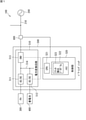
[1.電力変換装置の構成]
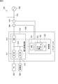
図1は、本実施形態に係る電力変換装置による系統連系の一構成例を示すブロック図である。電力システム100は、系統電源(交流電源)200と、太陽光発電装置300と、蓄電池400と、電力変換装置であるパワーコンディショナ500と、周波数センサ600とを備える。太陽光発電装置300はパワーコンディショナ500に接続され、発電電力がパワーコンディショナ500に供給される。蓄電池400はパワーコンディショナ500に接続され、パワーコンディショナ500に対して直流電力の入出力が可能である。即ち、蓄電池400は放電時にはパワーコンディショナ500へ直流電力を供給し、充電時にはパワーコンディショナ500から直流電力を受電する。
[1. Power converter configuration]
FIG. 1 is a block diagram showing a configuration example of grid interconnection by the power conversion device according to the present embodiment. The
系統電源200からは交流電路210が延びており、需要家の家電機器等の負荷に交流電力を供給する。パワーコンディショナ500は、太陽光発電装置300及び蓄電池400の少なくとも一方から与えられた直流電力を交流電力に変換する。パワーコンディショナ500は、交流電路210に接続され、電力系統側に交流電力を出力する。
An AC
パワーコンディショナ500は、電力変換回路510と、制御部520とを備える。電力変換回路510は、DC/DCコンバータ511,512と、インバータ513とを有する。DC/DCコンバータ511は、太陽光発電装置300に接続され、DC/DCコンバータ512は、蓄電池400に接続される。DC/DCコンバータ511,512は、図示しない昇圧チョッパ回路,降圧チョッパ回路等を含み、太陽光発電装置300及び蓄電池400から出力される直流電力を電圧変換する。DC/DCコンバータ511,512は、DCバス514を介してインバータ513に接続される。インバータ513は、DC/DCコンバータ511,512から出力される直流電力を交流電力に変換する。インバータ513は、変換した交流電力を交流電路210へ出力する。
The
制御部520は、電力変換回路510に接続され、電力変換回路510を制御する。制御部520は、CPU521と、メモリ522とを有する。メモリ522は、揮発性メモリであるRAMと、フラッシュメモリ等の非揮発性メモリとを有する(図示せず)。CPU521は、メモリ522に記憶されたコンピュータプログラムを実行することができる。かかるコンピュータプログラムには、後述するフリッカ検出処理を実行するためのフリッカ検出プログラム523が含まれる。
The
なお、制御部520は、CPU及びメモリなどの複数の半導体チップ等から構成することもできるし、CPU及びメモリ等の部分回路を内蔵する1つのLSIパッケージとして構成することもできる。また、制御部520を、ソフトウェアを実行可能なCPUにより構成するのではなく、同等の機能を実現するFPGA(Field-Programmable Gate Array)、ASIC(Application Specific Integrated Circuit)等のハードウェア回路とすることもできる。
The
周波数センサ600は、交流電路210に設けられ、系統電力の周波数である系統周波数を検出する。周波数センサ600は、制御部520に接続されており、系統周波数の検出結果(検出データ)を制御部520に送信する。なお、周波数センサ600に代えて電圧センサを交流電路210に設け、系統電力の周期より短いサンプリング周期で又は時間的に連続して電圧センサが系統電圧を検出し、電圧センサによって検出された系統電圧から制御部520等が系統周波数を計測する構成であってもよい。
The
[2.電力変換装置の機能]
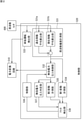
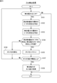
図2は、本実施形態に係るパワーコンディショナ500のフリッカ検出に関する機能を示す機能ブロック図である。制御部520は、周波数偏差計測部531と、無効電力注入制御部532と、単独運転検出部533として機能する。周波数偏差計測部531は、過去移動平均算出部531aと、現在移動平均算出部531bとを有する。過去移動平均算出部531aは、周波数センサ600から与えられた過去の系統周波数の移動平均値を算出する。例えば、系統周波数のサンプリング周期を5msとし、過去移動平均算出部531aは、200ms前の320ms間における系統周波数の移動平均値を算出する。現在移動平均算出部531bは、周波数センサ600から与えられた現在の系統周波数の移動平均値を算出する。例えば、現在移動平均算出部531bは、最新の40ms間における系統周波数の移動平均値を算出する。周波数偏差計測部531は、系統周波数の過去移動平均値から現在移動平均値を減算することで、系統周波数偏差を計測する。
[2. Functions of power converter]
FIG. 2 is a functional block diagram showing a function related to flicker detection of the
無効電力注入制御部532は、周波数偏差計測部531によって計測された系統周波数偏差に基づいて、無効電力量を算出し、この無効電力量を電力系統へ注入するよう電力変換回路510を制御する。
The ineffective power
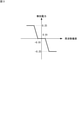
図3は、JEM1498に規定される注入無効電力を示すグラフである。無効電力量は、例えば、図3に示されるJEM1498規定の注入無効電力の特性にしたがって算出される。図3のグラフにおいて、縦軸は無効電力を示し、横軸は周波数偏差を示す。図3に示されるように、周波数偏差が-0.01Hzから0.01Hzの範囲は不感帯であり、無効電力は0である。周波数偏差が-0.01Hz以下では、注入無効電力は所定のゲインで増加し、0.25p.u.に到達すると、それ以下の周波数偏差では注入無効電力が0.25p.u.で固定される。周波数偏差が0.01以上の範囲では、上記と正負が逆転する。即ち、周波数偏差が0.01Hz以上では、注入無効電力は減少し(負の値が大きくなり)、-0.25p.u.に到達すると、それ以上の周波数偏差では注入無効電力が-0.25p.u.で固定される。 FIG. 3 is a graph showing the injection reactive power specified in JEM1498. The amount of reactive power is calculated, for example, according to the characteristics of the injected reactive power specified in JEM1498 shown in FIG. In the graph of FIG. 3, the vertical axis shows the reactive power and the horizontal axis shows the frequency deviation. As shown in FIG. 3, the frequency deviation in the range of −0.01 Hz to 0.01 Hz is a dead band, and the reactive power is 0. When the frequency deviation is -0.01 Hz or less, the injection reactive power increases at a predetermined gain, and 0.25 p. u. When the frequency deviation is less than that, the injection ineffective power becomes 0.25p. u. It is fixed with. In the range where the frequency deviation is 0.01 or more, the positive and negative are reversed from the above. That is, when the frequency deviation is 0.01 Hz or more, the injection reactive power decreases (the negative value becomes large), and -0.25 p. u. When the frequency deviation is higher than that, the injection reactive power becomes -0.25p. u. It is fixed with.
単独運転検出部533は、周波数センサ600から与えられた系統周波数を監視し、系統周波数に所定以上の変動が生じた場合に、単独運転状態と判断する。単独運転検出部533は、単独運転状態を検出すると、電力変換回路510を停止することにより、電力系統側への電力供給を停止する。
The isolated
制御部520は、第1変動計測部534と、第2変動計測部535と、フリッカ検出部(検出部)536としてさらに機能する。第1変動計測部534は、周波数偏差計測部531によって算出された系統周波数偏差の変動を計測する。系統周波数偏差の変動は、具体的には、系統周波数偏差の周期とすることができる。本実施形態では、第1変動計測部534は、系統周波数偏差のゼロクロス時刻を2点以上(一例として、数kHz~数十kHzのサンプリング周波数の場合に例えば2~10点)検出し、検出された2点以上のゼロクロス時刻から、系統周波数偏差の周期を計測する。
The
第2変動計測部535は、無効電力注入制御部532によって算出された無効電力量の変動を計測する。無効電力の変動は、具体的には、無効電力の周期とすることができる。本実施形態では、第2変動計測部535は、無効電力のゼロクロス時刻を2点以上(一例として、数kHz~数十kHzのサンプリング周波数の場合に例えば2~10点)検出し、検出された2点以上のゼロクロス時刻から、無効電力の周期を計測する。
The second
フリッカ検出部536は、第1変動計測部534によって計測された周波数偏差の変動と、第2変動計測部535によって計測された無効電力の変動とが同期しているか否かを判定することにより、フリッカを検出する。つまり、フリッカ検出部536は、周波数偏差の変動と無効電力の変動とが同期していると判定される場合にフリッカが発生していると判断し、周波数偏差の変動と無効電力の変動とが同期していないと判定される場合にフリッカが発生していないと判断する。周波数偏差の変動と無効電力の変動とが同期しているか否かは、例えば、周波数偏差の周期と無効電力の周期とが一致又は所定範囲内で近似しているか否か、周波数偏差のゼロクロス時刻と無効電力のゼロクロス時刻とが一致又は所定範囲内で近似しているか否か等により判定される。
The
制御部520は、無効電力注入判定部537と、制限部538としてさらに機能する。無効電力注入判定部537は、無効電力注入制御部532が算出する無効電力量に基づいて、単独運転検出による無効電力の注入中であるか否かを判定する。例えば、無効電力注入判定部537は、算出された無効電力量が所定の閾値以下であれば、無効電力の注入中ではないと判定し、算出された無効電力量が閾値より大きければ、無効電力の注入中であると判定することができる。
The
制限部538は、フリッカ検出部536によってフリッカが検出された場合に、無効電力の注入量を制限する。電力変換回路510が、太陽光発電装置300及び蓄電池400を含む直流電源から供給される直流電力を、無効電力が注入された交流電力へ変換し、交流電路210に交流電力を供給する。制限部は、フリッカ検出部536によってフリッカが検出された場合に、電力変換回路510による無効電力の注入量を制限する。例えば、制限部538は、無効電力注入制御部532に対して制限指令を出力し、無効電力注入制御部532は、制限指令を受け付けると、算出された無効電力量を制限する。無効電力量の制限は、例えば無効電力を0としてもよいし、算出された無効電力量を所定量(フリッカの抑制効果が得られる程度)減少させてもよい。
The limiting
[3.電力変換装置の動作]
以下、本実施形態に係るパワーコンディショナ500の動作について説明する。
[3. Operation of power converter]
Hereinafter, the operation of the
[3-1.単独運転検出]
まず、パワーコンディショナ500による単独運転検出について説明する。図4は、本実施形態に係るパワーコンディショナ500による単独運転検出処理の手順を示すフローチャートである。
[3-1. Independent operation detection]
First, the single operation detection by the
周波数センサ600は、交流電路210における系統電力の周波数である系統周波数を検出する。周波数センサ600からは、検出データが制御部520へ送信される。かかる系統周波数の検出は、例えば5ms毎に繰り返し行われる。CPU521は、周波数センサ600から系統周波数の検出データを受信すると、メモリ522に逐次記憶する(ステップS101)。
The
CPU521は、メモリ522に蓄積された系統周波数の時系列データから、所定時間過去の所定の移動平均時間分のデータを抽出し(ステップS102)、系統周波数の過去移動平均値を算出する(ステップS103)。
The
CPU521は、メモリ522に蓄積された系統周波数の時系列データから、所定の移動平均時間分の最新のデータを抽出し(ステップS104)、系統周波数の現在移動平均値を算出する(ステップS105)。
The
CPU521は、系統周波数の過去移動平均値と現在移動平均値との差である周波数偏差を算出する(ステップS106)。
The
CPU521は、算出された周波数偏差に基づいて、周波数フィードバックによる無効電力量を算出する(ステップS107)。この処理では、例えば、CPU521が、メモリ522に予め記憶されている無効電力量と周波数偏差との関係を示す無効電力の特性データを参照し、周波数偏差と当該特性データとによって、注入する無効電力量を算出する。特性データは、例えば図3に示されるJEM1498規定の特性とすることができる。
The
CPU521は、算出された無効電力量に基づいて、制御信号を生成し、これを電力変換回路510に出力して、無効電力を注入するよう電力変換回路510を制御する(ステップS108)。
The
CPU521は、メモリ522に格納される系統周波数の直近のデータを参照し、系統周波数に所定以上の変化があったか否かを判定する(ステップS109)。系統周波数に所定以上の変化があった場合には(ステップS109においてYES)、CPU521は単独運転状態であると判断し、電力変換回路510を停止させ(ステップS110)、単独運転検出処理を終了する。他方、系統周波数に所定以上の変化がない場合には(ステップS109においてNO)、CPU521は、ステップS101に処理を戻す。したがって、系統周波数に所定以上の変化がない間は、ステップS101~S109の処理が繰り返される。ステップS101~S109の周期は、例えば5msとされる。
The
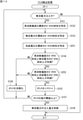
[3-2.フリッカ検出]
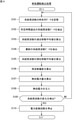
次に、パワーコンディショナ500によるフリッカ検出について説明する。図5は、本実施形態に係るパワーコンディショナ500によるフリッカ検出処理の手順を示すフローチャートである。
[3-2. Flicker detection]
Next, flicker detection by the
CPU521は、無効電力の注入中であるか否かを判定する(ステップS151)。この処理では、例えば、ステップS107により算出された最新の無効電力量が所定の閾値以下である場合に、CPU521が無効電力の注入が行われていないと判定し、無効電力量が閾値より大きい場合に、無効電力の注入中であると判定することができる。また、メモリ522に無効電力の注入中であることを示すフラグを設け、上記の単独運転検出処理において、無効電力量が閾値より大きい場合に当該フラグを立て、無効電力量が閾値以下である場合に当該フラグを倒すようにし、CPU521がフラグを参照することにより、無効電力の注入中であるか否かを判定することもできる。
The
無効電力を注入していない場合(ステップS151においてNO)、CPU521は、フリッカ検出処理を終了する。他方、無効電力の注入中である場合(ステップS151においてYES)、CPU521は、ステップS152に処理を移す。
When no invalid power is injected (NO in step S151), the
CPU521は、上記のステップS106により算出された周波数偏差を、メモリ522に逐次記憶する。これにより、メモリ522には、周波数偏差の時系列データが記憶される。
The
CPU521は、周波数偏差の時系列データから、周波数偏差の最新のゼロクロス時刻を特定する(ステップS152)。
The
CPU521は、上記のステップS107により算出された無効電力量を、メモリ522に逐次記憶する。これにより、メモリ522には、無効電力量の時系列データが記憶される。
The
CPU521は、無効電力量の時系列データから、無効電力の最新のゼロクロス時刻を特定する(ステップS153)。
The
CPU521は、周波数偏差のゼロクロス時刻と無効電力のゼロクロス時刻との差を算出し、この差が所定の閾値範囲内であるか否かを判定することにより、周波数偏差のゼロクロス時刻と無効電力のゼロクロス時刻とが同期しているか否かを判定する(ステップS154)。差が閾値範囲内である場合、即ち、周波数偏差のゼロクロス時刻と無効電力のゼロクロス時刻とが同期している場合(ステップS154においてYES)、CPU521は、メモリ522に設けられたカウンタの値を1つインクリメントする(ステップS155)。なお、カウンタの初期値は0である。他方、差が閾値範囲を超えている場合、即ち、周波数偏差のゼロクロス時刻と無効電力のゼロクロス時刻とが同期していない場合(ステップS154においてNO)、CPU521は、カウンタを初期化し(ステップS156)、ステップS151へ処理を戻す。
The
ステップS155の処理の後、CPU521は、カウンタの値が所定の閾値以上であるか否かを判定する(ステップS157)。ここで、閾値は2以上の適宜の整数に設定される。カウンタ値が閾値未満である場合(ステップS157においてNO)、CPU521は、ステップS151へ処理を戻す。ここで、カウンタは初期化されずにステップS151からの処理が実行される。このため、再度周波数偏差のゼロクロス時刻と無効電力のゼロクロス時刻とが同期していれば、カウンタ値はインクリメントされる。
After the process of step S155, the
カウンタ値が閾値以上である場合(ステップS157においてYES)、CPU521は、単独運転検出機能に起因したフリッカを検出する。閾値が2以上に設定されることで、ゼロクロス時刻が2点以上で比較される。周波数偏差及び無効電力は周期的に変動するため、隣り合うゼロクロス時刻は周期に対応する。したがって、2点以上のゼロクロス時刻を比較することで、周波数偏差及び無効電力の周期が同期しているか否かを評価することができる。即ち、2回以上連続して周波数偏差及び無効電力のゼロクロス時刻が近似している場合、周波数偏差の変動と無効電力の変動とは同期していると判断される。
When the counter value is equal to or greater than the threshold value (YES in step S157), the
カウンタ値が閾値以上の場合、CPU521は、無効電力の注入量を制限する(ステップS158)。この処理では、ステップS107により算出される無効電力量を減少させることにより、無効電力量が制限される。なお、電力変換回路510を停止させることで、無効電力量を制限することもできる。無効電力の注入量を制限すると、CPU521は、フリッカ検出処理を終了する。
When the counter value is equal to or greater than the threshold value, the
[4.評価試験]
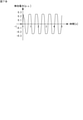
発明者らは、パワーコンディショナの系統連系のモデルをコンピュータに構築し、当該モデルを使用してフリッカ現象のシミュレーションを実施した。図6は、シミュレーションに使用した系統連系のモデルを示す回路図である。モデル10は、パワーコンディショナ11と、系統電源12と、インダクタンス成分Lと、抵抗成分R,R’とによって構成される。パワーコンディショナ11の出力側は、直列インダクタンス成分L及び直列抵抗成分Rを介して系統電源12に接続される。また、系統電源12は抵抗成分R’に並列接続される。図6におけるVoutはパワーコンディショナ11の出力電圧を、Iはパワーコンディショナ11の出力電流を示す。また、Ipを有効電力による電流、Iqを無効電力による電流とすると、I=Ip+Iqとなる。シミュレーションでは、逆潮流方向を正としている。系統電源12の電圧Vsysは、式(1)のように定義した。
![]()
The inventors built a model of the grid interconnection of the power conditioner on a computer, and used the model to simulate the flicker phenomenon. FIG. 6 is a circuit diagram showing a grid interconnection model used in the simulation. The
![]()
有効電力による電流Ipが流れると、抵抗成分Rによって電圧VRが発生する。また、無効電力による電流Iqが流れると、インダクタンス成分Lによって電圧VLが発生する。 When the current Ip due to the active power flows, the voltage VR is generated by the resistance component R. Further, when the current Iq due to the reactive power flows, the voltage VL is generated by the inductance component L.
発明者らは、上記のモデル10に対して、周期的に更新される無効電力を注入した場合の動作のシミュレーションを行った。一般社団法人日本電機工業会(JEMA)によって制定される標準規格JEM1498「分散型電源用単相パワーコンディショナの標準形能動的単独運転検出方式(ステップ注入付周波数フィードバック方式)」では、無効電力の更新周期を5msとし、系統電源の周波数偏差を、200ms前の320ms間における移動平均周波数値から最新の40ms間における移動平均周波数値を減算した結果としている。シミュレーションでは、無効電力の更新周期を系統電源12の交流周期に、周波数偏差を10周期前の16周期分平均から最新の2周期分平均を減算した結果にそれぞれ簡略化した。
The inventors simulated the operation of the
シミュレーションでは、図3に示されるJEM1498に規定される注入無効電力を用いた。 In the simulation, the injection reactive power specified in JEM1498 shown in FIG. 3 was used.
図7A~図7Cは、シミュレーションの結果を示すグラフであり、図7Aは周波数偏差の変動を示し、図7Bは無効電力の変動を示し、図7Cは系統電圧の変動を示す。シミュレーションでは、何らかの原因によって周波数が変動した場合を想定し、時間t=0において、約-0.7Hzの周波数偏差を初期値として与えた。この結果、周波数フィードバック(単独運転検出)機能によって、正の無効電力が発生する。正の無効電力が発生すると、インダクタンス成分Lによって負の電圧VLが発生する。 7A to 7C are graphs showing the results of the simulation, FIG. 7A shows the fluctuation of the frequency deviation, FIG. 7B shows the fluctuation of the reactive power, and FIG. 7C shows the fluctuation of the system voltage. In the simulation, assuming that the frequency fluctuates for some reason, a frequency deviation of about −0.7 Hz is given as an initial value at time t = 0. As a result, the frequency feedback (isolated operation detection) function generates positive reactive power. When a positive reactive power is generated, a negative voltage VL is generated by the inductance component L.
周波数偏差は、過去の移動平均周波数値の増減と、現在の移動平均周波数値の増減とが反転を繰り返す。即ち、ある時刻(例えば、t=約0.4)においては、過去の移動平均周波数値が現在の移動平均周波数値より大きいが、その後の時刻(例えば、t=約0.8)においては、過去の移動平均周波数値が現在の移動平均周波数値より小さくなる。また、さらにその後の時刻(例えば、t=約1.2)においては、過去の移動平均周波数値が現在の移動平均周波数値より再び大きくなる。したがって、図7Aに示されるように、周波数偏差が周期的に変動する。 As for the frequency deviation, the increase / decrease of the past moving average frequency value and the increase / decrease of the current moving average frequency value are repeatedly reversed. That is, at a certain time (for example, t = about 0.4), the past moving average frequency value is larger than the current moving average frequency value, but at a subsequent time (for example, t = about 0.8), The past moving average frequency value becomes smaller than the current moving average frequency value. Further, at a later time (for example, t = about 1.2), the past moving average frequency value becomes larger than the current moving average frequency value again. Therefore, as shown in FIG. 7A, the frequency deviation fluctuates periodically.
上記の周波数偏差の変動により、周波数偏差が0.01以上の値となると、周波数フィードバック機能によって、負の無効電力が発生する。負の無効電力が発生すると、インダクタンス成分Lによって正の電圧VLが発生する。再び周波数偏差が-0.01以下の値となると、周波数フィードバック機能によって、正の無効電力が発生する。正の無効電力が発生すると、インダクタンス成分Lによって負の電圧VLが発生する。このように、注入無効電力と、系統電圧とが周期的に変動する(図7B及び図7C参照)。これがフリッカ現象であり、系統電圧の周期的変動がフリッカである。 When the frequency deviation becomes a value of 0.01 or more due to the fluctuation of the frequency deviation described above, the frequency feedback function generates negative reactive power. When a negative reactive power is generated, a positive voltage VL is generated by the inductance component L. When the frequency deviation becomes a value of −0.01 or less again, the frequency feedback function generates positive reactive power. When a positive reactive power is generated, a negative voltage VL is generated by the inductance component L. In this way, the injection reactive power and the system voltage fluctuate periodically (see FIGS. 7B and 7C). This is the flicker phenomenon, and the periodic fluctuation of the system voltage is the flicker.
図7A~図7Cに示されるように、周波数偏差の周期と、無効電力の周期と、系統電圧の周期とは同一である。また、周波数偏差の位相と無効電力の位相とは互いに逆である。一方、周波数偏差の位相と系統電圧の位相とは同じである。即ち、無効電力の位相と系統電圧の位相は互いに逆である。 As shown in FIGS. 7A to 7C, the frequency deviation cycle, the reactive power cycle, and the system voltage cycle are the same. Also, the phase of the frequency deviation and the phase of the reactive power are opposite to each other. On the other hand, the phase of the frequency deviation and the phase of the system voltage are the same. That is, the phase of the reactive power and the phase of the system voltage are opposite to each other.
本実施形態に係るパワーコンディショナ500は、周波数偏差の変動と、無効電力の変動とが同期しているか否かに基づいて無効電力に起因するフリッカを検出する。上記のように、無効電力に起因するフリッカは、同一周期で周波数偏差と無効電力とが変動するという周期性を有するため、本実施形態に係るパワーコンディショナ500によって、フリッカの発生を正確に検出することができることが分かる。
The
また、パワーコンディショナ500は、単独運転検出による無効電力の注入中であるか否かを判定し、無効電力の注入中である場合に、フリッカを検出するため、フリッカの検出を効率的に行うことができる。
Further, the
また、パワーコンディショナ500は、周波数偏差のゼロクロス時刻と、無効電力のゼロクロス時刻とを検出する。周波数偏差のゼロクロス時刻は周波数偏差の変動を反映しており、無効電力のゼロクロス時刻は無効電力の変動を反映している。したがって、これらのゼロクロス時刻を用いることで、周波数偏差の変動と無効電力の変動とが同期しているか否かを正確に判定することができ、単独運転検出によるフリッカの検出精度が向上する。
Further, the
また、パワーコンディショナ500は、周波数偏差のゼロクロス時刻を2点以上検出することで、周期的に変動する周波数偏差の周期を計測し、無効電力のゼロクロス時刻を2点以上検出することで、周期的に変動する無効電力の周期を計測することができる。これにより、周波数偏差の周期と、無効電力の周期とによって、周波数偏差の変動と無効電力の変動とが同期しているか否かを正確に判定することができ、単独運転検出によるフリッカの検出精度が向上する。
Further, the
また、パワーコンディショナ500は、周波数偏差のゼロクロス時刻と、無効電力のゼロクロス時刻とが同期する回数をカウントし、この回数に基づいてフリッカを検出する。これにより、計測誤差によるフリッカ検出精度への影響を抑制することができ、単独運転検出によるフリッカの検出精度がより一層向上する。
Further, the
また、パワーコンディショナ500は、フリッカが検出された場合に、無効電力の注入量を制限する。これにより、フリッカを抑制することができる。
Further, the
[5.変形例]
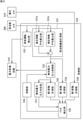
本変形例に係るパワーコンディショナ500は、周波数偏差の変動及び注入無効電力の変動に加えて、系統電源の電圧(系統電圧)を用いてフリッカを検出する。図8は、本変形例に係るパワーコンディショナによる系統連系の一構成例を示すブロック図である。本変形例では、電力システム100が、電圧センサ610を備える。
[5. Modification example]
The
電圧センサ610は、交流電路210に設けられ、系統電圧を検出する。電圧センサ610は、制御部520に接続されており、系統電圧の検出結果(検出データ)を制御部520に送信する。
The
図9は、本変形例に係るパワーコンディショナ500のフリッカ検出に関する機能を示す機能ブロック図である。制御部520は、第3変動計測部539として機能する。第3変動計測部539は、電圧センサ610によって検出された系統電圧の変動を計測する。系統電圧の変動は、具体的には、系統電圧の周期とすることができる。本変形例では、第3変動計測部539は、系統電圧のゼロクロス時刻を2点以上(一例として、数kHz~数十kHzのサンプリング周波数の場合に例えば2~10点)検出し、検出された2点以上のゼロクロス時刻から、系統電圧の周期を計測する。
FIG. 9 is a functional block diagram showing a function related to flicker detection of the
フリッカ検出部536は、第1変動計測部534によって計測された周波数偏差の変動と、第2変動計測部535によって計測された無効電力の変動とが同期しているか否かを判定し、また、第1変動計測部534によって計測された周波数偏差の変動と、第3変動計測部539によって計測された系統電圧の変動とが同期しているか否かを判定することにより、フリッカを検出する。つまり、フリッカ検出部536は、周波数偏差の変動と無効電力の変動とが同期していると判定され、且つ、周波数偏差の変動と系統電圧の変動とが同期していると判定される場合にフリッカが発生していると判断し、周波数偏差の変動と無効電力の変動との同期、及び周波数偏差の変動と系統電圧の変動との同期の少なくとも何れかが成立しない場合に、フリッカが発生していないと判断する。周波数偏差の変動と系統電圧の変動とが同期しているか否かは、例えば、周波数偏差の周期と系統電圧の周期とが一致又は所定範囲内で近似しているか否か、周波数偏差のゼロクロス時刻と系統電圧のゼロクロス時刻とが一致又は所定範囲内で近似しているか否か等により判定される。
The
次に、本変形例に係るパワーコンディショナ500によるフリッカ検出の動作について説明する。図10は、本変形例に係るパワーコンディショナ500によるフリッカ検出処理の手順を示すフローチャートである。
Next, the operation of flicker detection by the
CPU521は、無効電力の注入中であるか否かを判定する(ステップS151)。無効電力を注入していない場合(ステップS151においてNO)、CPU521は、フリッカ検出処理を終了する。他方、無効電力の注入中である場合(ステップS151においてYES)、CPU521は、ステップS152に処理を移す。
The
CPU521は、周波数偏差の時系列データから、周波数偏差の最新のゼロクロス時刻を特定する(ステップS152)。また、CPU521は、無効電力量の時系列データから、無効電力の最新のゼロクロス時刻を特定する(ステップS153)。
The
CPU521は、電圧センサ610により検出された系統電圧を、メモリ522に逐次記憶する。これにより、メモリ522には、系統電圧の時系列データが記憶される。
The
CPU521は、系統電圧の時系列データから、系統電圧の最新のゼロクロス時刻を特定する(ステップS251)。
The
CPU521は、周波数偏差のゼロクロス時刻と無効電力のゼロクロス時刻との差を算出し、この差が所定の閾値範囲内であるか否かを判定することにより、周波数偏差のゼロクロス時刻と無効電力のゼロクロス時刻とが同期しているか否かを判定する(ステップS154)。差が閾値範囲内である場合、即ち、周波数偏差のゼロクロス時刻と無効電力のゼロクロス時刻とが同期している場合(ステップS154においてYES)、CPU521は、周波数偏差のゼロクロス時刻と系統電圧のゼロクロス時刻との差を算出し、この差が所定の閾値範囲内であるか否かを判定することにより、周波数偏差のゼロクロス時刻と系統電圧のゼロクロス時刻とが同期しているか否かを判定する(ステップS252)。差が閾値範囲内である場合、即ち、周波数偏差のゼロクロス時刻と系統電圧のゼロクロス時刻とが同期している場合(ステップS252においてYES)、CPU521は、メモリ522に設けられたカウンタの値を1つインクリメントする(ステップS155)。なお、カウンタの初期値は0である。
The
周波数偏差のゼロクロス時刻と無効電力のゼロクロス時刻とが同期していない場合(ステップS154においてNO)、又は、周波数偏差のゼロクロス時刻と系統電圧のゼロクロス時刻とが同期していない場合(ステップS252においてNO)、CPU521は、カウンタを初期化し(ステップS156)、ステップS151へ処理を戻す。
When the zero cross time of the frequency deviation and the zero cross time of the reactive power are not synchronized (NO in step S154), or when the zero cross time of the frequency deviation and the zero cross time of the system voltage are not synchronized (NO in step S252). ), The
ステップS155の処理の後、CPU521は、カウンタの値が所定の閾値以上であるか否かを判定する(ステップS157)。ここで、閾値は2以上の適宜の整数に設定される。カウンタ値が閾値未満である場合(ステップS157においてNO)、CPU521は、ステップS151へ処理を戻す。ここで、カウンタは初期化されずにステップS151からの処理が実行される。このため、周波数偏差のゼロクロス時刻と無効電力のゼロクロス時刻とが再度同期し、且つ、周波数偏差のゼロクロス時刻と系統電圧のゼロクロス時刻とが再度同期していれば、カウンタ値はインクリメントされる。
After the process of step S155, the
カウンタ値が閾値以上である場合(ステップS157においてYES)、CPU521は、単独運転検出機能に起因したフリッカを検出する。閾値が2以上に設定されることで、ゼロクロス時刻が2点以上で比較される。周波数偏差、無効電力及び系統電圧のそれぞれは周期的に変動するため、隣り合うゼロクロス時刻は周期(周期の1/2)に対応する。したがって、2点以上のゼロクロス時刻を比較することで、周波数偏差及び無効電力の周期が合致しているか否か、並びに、周波数偏差及び系統電圧の周期が合致しているか否かを評価することができる。即ち、2回以上連続して周波数偏差及び無効電力のゼロクロス時刻が同期し、且つ、周波数偏差及び系統電圧のゼロクロス時刻が同期している場合、周波数偏差の変動、無効電力の変動、及び系統電圧の変動のそれぞれは同期していると判断される。
When the counter value is equal to or greater than the threshold value (YES in step S157), the
カウンタ値が閾値以上の場合、CPU521は、無効電力の注入量を制限する(ステップS158)。無効電力の注入量を制限すると、CPU521は、フリッカ検出処理を終了する。
When the counter value is equal to or greater than the threshold value, the
以上のように、本変形例に係るパワーコンディショナ500は、周波数偏差の変動及び注入無効電力の変動に加えて、系統電源の電圧を用いることで、単独運転検出によるフリッカをさらに精度よく検出することができる。
As described above, the
なお、上記の変形例では、周波数偏差のゼロクロス時刻と無効電力のゼロクロス時刻とを比較し、周波数偏差のゼロクロス時刻と系統電圧のゼロクロス時刻とを比較する構成としたが、周波数偏差のゼロクロス時刻と無効電力のゼロクロス時刻とを比較し、無効電力のゼロクロス時刻と系統電圧のゼロクロス時刻とを比較してもよいし、周波数偏差のゼロクロス時刻、無効電力のゼロクロス時刻、及び系統電圧のゼロクロス時刻をまとめて比較してもよい。 In the above modification, the zero-cross time of the frequency deviation and the zero-cross time of the ineffective power are compared, and the zero-cross time of the frequency deviation and the zero-cross time of the system voltage are compared. You may compare the zero-cross time of the ineffective power with the zero-cross time of the ineffective power and the zero-cross time of the system voltage, or summarize the zero-cross time of the frequency deviation, the zero-cross time of the ineffective power, and the zero-cross time of the system voltage. May be compared.
[6.補記]
なお、今回開示された実施の形態はすべての点で例示であって制限的なものではないと考えられるべきである。本発明の範囲は特許請求の範囲によって示され、特許請求の範囲と均等の意味及び範囲内での全ての変更が含まれることが意図される。
[6. Supplement]
It should be noted that the embodiments disclosed this time are exemplary in all respects and are not restrictive. The scope of the present invention is indicated by the scope of claims and is intended to include all modifications within the meaning and scope equivalent to the scope of claims.
10 モデル
11 パワーコンディショナ
12 系統電源
100 電力システム
200 系統電源
300 太陽光発電装置
400 蓄電池
500 パワーコンディショナ(電力変換装置)
600 周波数センサ
210 交流電路
510 電力変換回路
511,512 DC/DCコンバータ
513 インバータ
514 DCバス
520 制御部
521 CPU
522 メモリ
523 検出プログラム
531 周波数偏差計測部
531a 過去移動平均算出部
531b 現在移動平均算出部
532 無効電力注入制御部
533 単独運転検出部
534 第1変動計測部
535 第2変動計測部
536 フリッカ検出部(検出部)
537 無効電力注入判定部
538 制限部
539 第3変動計測部
610 電圧センサ
10
600
522
537 Reactive power
Claims (8)
前記系統電源が接続される交流電路における周波数偏差の変動を計測する第1変動計測部と、
前記交流電路に注入される無効電力の変動を計測する第2変動計測部と、
前記第1変動計測部によって計測された前記周波数偏差の変動と、前記第2変動計測部によって計測された前記無効電力の変動とが同期しているか否かに基づいて、前記無効電力に起因するフリッカを検出する検出部と、
を備える、
電力変換装置。 It is a power converter that is connected to the grid power supply.
The first fluctuation measuring unit that measures the fluctuation of the frequency deviation in the AC electric circuit to which the system power supply is connected, and
The second fluctuation measuring unit that measures the fluctuation of the reactive power injected into the AC electric circuit, and
It is caused by the reactive power based on whether or not the fluctuation of the frequency deviation measured by the first fluctuation measuring unit and the fluctuation of the reactive power measured by the second fluctuation measuring unit are synchronized with each other. A detector that detects flicker and
To prepare
Power converter.
前記検出部は、前記無効電力注入判定部によって前記無効電力の注入中と判定された場合に、前記フリッカを検出する検出処理を実行する、
請求項1に記載の電力変換装置。 Further, it is provided with an invalid power injection determination unit for determining whether or not the invalid power is being injected by detection of independent operation.
The detection unit executes a detection process for detecting the flicker when it is determined by the ineffective power injection determination unit that the ineffective power is being injected.
The power conversion device according to claim 1.
前記第2変動計測部は、前記無効電力のゼロクロス時刻に基づいて前記無効電力の変動を計測する、
請求項1又は2に記載の電力変換装置。 The first fluctuation measuring unit measures the fluctuation of the frequency deviation based on the zero cross time of the frequency deviation, and measures the fluctuation of the frequency deviation.
The second fluctuation measuring unit measures the fluctuation of the reactive power based on the zero cross time of the reactive power.
The power conversion device according to claim 1 or 2.
前記第2変動計測部は、少なくとも2点の前記無効電力のゼロクロス時刻に基づいて、前記無効電力の変動として前記無効電力の周期を計測する、
請求項3に記載の電力変換装置。 The first fluctuation measuring unit measures the period of the frequency deviation as the fluctuation of the frequency deviation based on the zero cross time of the frequency deviation at at least two points.
The second fluctuation measuring unit measures the cycle of the reactive power as the fluctuation of the reactive power based on the zero cross time of the reactive power at at least two points.
The power conversion device according to claim 3.
請求項3又は4に記載の電力変換装置。 The detection unit synchronizes the fluctuation of the frequency deviation with the fluctuation of the reactive power based on whether or not the zero cross time of the frequency deviation and the zero cross time of the reactive power are synchronized more than a predetermined number of times. Judging whether or not it is done,
The power conversion device according to claim 3 or 4.
請求項1から請求項5の何れか1項に記載の電力変換装置。 Further, a limiting unit for limiting the injection amount of the reactive power when the flicker is detected by the detecting unit is provided.
The power conversion device according to any one of claims 1 to 5.
前記検出部は、前記第3変動計測部によって計測された前記電圧の変動にさらに基づいて、前記フリッカを検出する、
請求項1から請求項6の何れか1項に記載の電力変換装置。 Further, a third fluctuation measuring unit for measuring the fluctuation of the voltage of the AC electric circuit is provided.
The detection unit detects the flicker based on the fluctuation of the voltage measured by the third fluctuation measurement unit.
The power conversion device according to any one of claims 1 to 6.
前記系統電源が接続される交流電路における周波数偏差の変動を計測し、
前記交流電路に注入される無効電力の変動を計測し、
計測された前記周波数偏差の変動と、計測された前記無効電力の変動とが同期しているか否かに基づいて、前記無効電力に起因するフリッカを検出する、
フリッカ検出方法。 It is a flicker detection method that detects flicker in the grid interconnection between the grid power supply and the power converter.
The fluctuation of the frequency deviation in the AC electric circuit to which the system power supply is connected is measured and
The fluctuation of the reactive power injected into the AC electric circuit is measured and
Flicker caused by the reactive power is detected based on whether or not the measured fluctuation of the frequency deviation and the measured fluctuation of the reactive power are synchronized.
Flicker detection method.
Priority Applications (1)
| Application Number | Priority Date | Filing Date | Title |
|---|---|---|---|
| JP2018136674A JP6996444B2 (en) | 2018-07-20 | 2018-07-20 | Power converter and flicker detection method |
Applications Claiming Priority (1)
| Application Number | Priority Date | Filing Date | Title |
|---|---|---|---|
| JP2018136674A JP6996444B2 (en) | 2018-07-20 | 2018-07-20 | Power converter and flicker detection method |
Publications (2)
| Publication Number | Publication Date |
|---|---|
| JP2020014358A JP2020014358A (en) | 2020-01-23 |
| JP6996444B2 true JP6996444B2 (en) | 2022-01-17 |
Family
ID=69170154
Family Applications (1)
| Application Number | Title | Priority Date | Filing Date |
|---|---|---|---|
| JP2018136674A Active JP6996444B2 (en) | 2018-07-20 | 2018-07-20 | Power converter and flicker detection method |
Country Status (1)
| Country | Link |
|---|---|
| JP (1) | JP6996444B2 (en) |
Families Citing this family (3)
| Publication number | Priority date | Publication date | Assignee | Title |
|---|---|---|---|---|
| EP4287436A4 (en) * | 2021-01-29 | 2025-05-14 | Toshiba Mitsubishi-Electric Industrial Systems Corporation | FLICKER SUPPRESSION DEVICE AND FLICKER SUPPRESSION CONTROL METHOD |
| JP7727560B2 (en) * | 2022-01-12 | 2025-08-21 | 株式会社ダイヘン | Islanding operation detection device, islanding operation detection method, and power conditioner equipped with islanding operation detection device |
| CN116545023B (en) * | 2023-07-06 | 2023-11-14 | 中国电力科学研究院有限公司 | Simulation verification method and device for grid-connected point flicker characteristics of wind turbine generator |
Citations (7)
| Publication number | Priority date | Publication date | Assignee | Title |
|---|---|---|---|---|
| JP2007202266A (en) | 2006-01-25 | 2007-08-09 | Omron Corp | Isolated operation detection method, distributed power supply isolated operation detection control device, isolated operation detection device, and distributed power supply |
| JP2013042576A (en) | 2011-08-11 | 2013-02-28 | Purpose Co Ltd | Distributed power supply, control program thereof and control method thereof |
| WO2013142553A2 (en) | 2012-03-23 | 2013-09-26 | General Electric Company | System and method for islanding detection and protection |
| JP2015082886A (en) | 2013-10-22 | 2015-04-27 | 株式会社日立情報通信エンジニアリング | Power conversion system, and method of detecting single operation of power conversion system |
| JP2016012994A (en) | 2014-06-30 | 2016-01-21 | パナソニックIpマネジメント株式会社 | Electric power converter |
| JP2016131441A (en) | 2015-01-13 | 2016-07-21 | オムロン株式会社 | Isolated operation detector, controller, power conditioner, power supply system, and isolated operation detection method |
| JP2018064328A (en) | 2016-10-11 | 2018-04-19 | シャープ株式会社 | Power converter and control method thereof |
-
2018
- 2018-07-20 JP JP2018136674A patent/JP6996444B2/en active Active
Patent Citations (7)
| Publication number | Priority date | Publication date | Assignee | Title |
|---|---|---|---|---|
| JP2007202266A (en) | 2006-01-25 | 2007-08-09 | Omron Corp | Isolated operation detection method, distributed power supply isolated operation detection control device, isolated operation detection device, and distributed power supply |
| JP2013042576A (en) | 2011-08-11 | 2013-02-28 | Purpose Co Ltd | Distributed power supply, control program thereof and control method thereof |
| WO2013142553A2 (en) | 2012-03-23 | 2013-09-26 | General Electric Company | System and method for islanding detection and protection |
| JP2015082886A (en) | 2013-10-22 | 2015-04-27 | 株式会社日立情報通信エンジニアリング | Power conversion system, and method of detecting single operation of power conversion system |
| JP2016012994A (en) | 2014-06-30 | 2016-01-21 | パナソニックIpマネジメント株式会社 | Electric power converter |
| JP2016131441A (en) | 2015-01-13 | 2016-07-21 | オムロン株式会社 | Isolated operation detector, controller, power conditioner, power supply system, and isolated operation detection method |
| JP2018064328A (en) | 2016-10-11 | 2018-04-19 | シャープ株式会社 | Power converter and control method thereof |
Also Published As
| Publication number | Publication date |
|---|---|
| JP2020014358A (en) | 2020-01-23 |
Similar Documents
| Publication | Publication Date | Title |
|---|---|---|
| JP6044114B2 (en) | State determination device, power storage device, and state determination method | |
| JP4818468B1 (en) | Charge state estimation device | |
| JP6996444B2 (en) | Power converter and flicker detection method | |
| US10031185B2 (en) | Method for determining a state of charge and remaining operation life of a battery | |
| US11063436B2 (en) | Power conversion device | |
| JP5507669B2 (en) | Power supply system, power supply method, and control program for power supply system | |
| US11329471B2 (en) | Arc detection circuit, breaker system, connection box system, power conditioner, micro inverter, DC optimizer, and arc detection method | |
| CN106464148B (en) | Method for monitoring DC link capacitance in power converters | |
| CN108369257A (en) | Capacity maintenance rate estimating device or capacity maintenance rate estimate method | |
| JPWO2011078215A1 (en) | Power supply method, computer-readable recording medium, and power generation system | |
| KR102693893B1 (en) | Battery life prediction device and method of operation thereof | |
| JP5475019B2 (en) | Power supply method, computer-readable recording medium, and power generation system | |
| CN109669342B (en) | Method and device for detecting convergence state of converter control system, storage medium | |
| JP5174968B2 (en) | Method and controller for determining the state of charge of a battery | |
| US8866446B2 (en) | End-of-discharge voltage correction device and end-of-discharge voltage correction method | |
| JP2018151269A (en) | Battery state estimation device | |
| CN104821598B (en) | A kind of control method of grid-connected inverter and control device | |
| JP2020092532A (en) | Power storage system and current sensor abnormality determination method | |
| JP7040337B2 (en) | Power converter and flicker control method | |
| CN106385235B (en) | Present site detection device reversal connection detection method and reversal connection detection device | |
| CN108574297B (en) | Inverter control method, device and system of wind generating set | |
| JP5959293B2 (en) | Insulation resistance measuring device and insulation resistance measuring method | |
| CN117851955B (en) | Flexible-direct-current capacitor state detection method and system | |
| CN112737295B (en) | Method for suppressing direct current component and related equipment | |
| JP6610012B2 (en) | Isolated operation detection method and isolated operation detection device |
Legal Events
| Date | Code | Title | Description |
|---|---|---|---|
| A621 | Written request for application examination |
Free format text: JAPANESE INTERMEDIATE CODE: A621 Effective date: 20210121 |
|
| A977 | Report on retrieval |
Free format text: JAPANESE INTERMEDIATE CODE: A971007 Effective date: 20211110 |
|
| TRDD | Decision of grant or rejection written | ||
| A01 | Written decision to grant a patent or to grant a registration (utility model) |
Free format text: JAPANESE INTERMEDIATE CODE: A01 Effective date: 20211116 |
|
| A61 | First payment of annual fees (during grant procedure) |
Free format text: JAPANESE INTERMEDIATE CODE: A61 Effective date: 20211129 |
|
| R150 | Certificate of patent or registration of utility model |
Ref document number: 6996444 Country of ref document: JP Free format text: JAPANESE INTERMEDIATE CODE: R150 |
|
| R250 | Receipt of annual fees |
Free format text: JAPANESE INTERMEDIATE CODE: R250 |
|
| R250 | Receipt of annual fees |
Free format text: JAPANESE INTERMEDIATE CODE: R250 |