JP6996432B2 - CO2 separation system for mounting on vehicles that use an internal combustion engine as power - Google Patents
CO2 separation system for mounting on vehicles that use an internal combustion engine as power Download PDFInfo
- Publication number
- JP6996432B2 JP6996432B2 JP2018117315A JP2018117315A JP6996432B2 JP 6996432 B2 JP6996432 B2 JP 6996432B2 JP 2018117315 A JP2018117315 A JP 2018117315A JP 2018117315 A JP2018117315 A JP 2018117315A JP 6996432 B2 JP6996432 B2 JP 6996432B2
- Authority
- JP
- Japan
- Prior art keywords
- separation device
- permeation
- supply side
- flow path
- combustion engine
- Prior art date
- Legal status (The legal status is an assumption and is not a legal conclusion. Google has not performed a legal analysis and makes no representation as to the accuracy of the status listed.)
- Expired - Fee Related
Links
Images


Classifications
-
- B—PERFORMING OPERATIONS; TRANSPORTING
- B01—PHYSICAL OR CHEMICAL PROCESSES OR APPARATUS IN GENERAL
- B01D—SEPARATION
- B01D53/00—Separation of gases or vapours; Recovering vapours of volatile solvents from gases; Chemical or biological purification of waste gases, e.g. engine exhaust gases, smoke, fumes, flue gases, aerosols
- B01D53/22—Separation of gases or vapours; Recovering vapours of volatile solvents from gases; Chemical or biological purification of waste gases, e.g. engine exhaust gases, smoke, fumes, flue gases, aerosols by diffusion
- B01D53/229—Integrated processes (Diffusion and at least one other process, e.g. adsorption, absorption)
-
- B—PERFORMING OPERATIONS; TRANSPORTING
- B01—PHYSICAL OR CHEMICAL PROCESSES OR APPARATUS IN GENERAL
- B01D—SEPARATION
- B01D53/00—Separation of gases or vapours; Recovering vapours of volatile solvents from gases; Chemical or biological purification of waste gases, e.g. engine exhaust gases, smoke, fumes, flue gases, aerosols
- B01D53/22—Separation of gases or vapours; Recovering vapours of volatile solvents from gases; Chemical or biological purification of waste gases, e.g. engine exhaust gases, smoke, fumes, flue gases, aerosols by diffusion
- B01D53/225—Multiple stage diffusion
- B01D53/226—Multiple stage diffusion in serial connexion
-
- B—PERFORMING OPERATIONS; TRANSPORTING
- B01—PHYSICAL OR CHEMICAL PROCESSES OR APPARATUS IN GENERAL
- B01D—SEPARATION
- B01D53/00—Separation of gases or vapours; Recovering vapours of volatile solvents from gases; Chemical or biological purification of waste gases, e.g. engine exhaust gases, smoke, fumes, flue gases, aerosols
- B01D53/22—Separation of gases or vapours; Recovering vapours of volatile solvents from gases; Chemical or biological purification of waste gases, e.g. engine exhaust gases, smoke, fumes, flue gases, aerosols by diffusion
- B01D53/225—Multiple stage diffusion
- B01D53/227—Multiple stage diffusion in parallel connexion
-
- B—PERFORMING OPERATIONS; TRANSPORTING
- B01—PHYSICAL OR CHEMICAL PROCESSES OR APPARATUS IN GENERAL
- B01D—SEPARATION
- B01D53/00—Separation of gases or vapours; Recovering vapours of volatile solvents from gases; Chemical or biological purification of waste gases, e.g. engine exhaust gases, smoke, fumes, flue gases, aerosols
- B01D53/34—Chemical or biological purification of waste gases
- B01D53/46—Removing components of defined structure
- B01D53/62—Carbon oxides
-
- B—PERFORMING OPERATIONS; TRANSPORTING
- B01—PHYSICAL OR CHEMICAL PROCESSES OR APPARATUS IN GENERAL
- B01D—SEPARATION
- B01D53/00—Separation of gases or vapours; Recovering vapours of volatile solvents from gases; Chemical or biological purification of waste gases, e.g. engine exhaust gases, smoke, fumes, flue gases, aerosols
- B01D53/34—Chemical or biological purification of waste gases
- B01D53/92—Chemical or biological purification of waste gases of engine exhaust gases
-
- F—MECHANICAL ENGINEERING; LIGHTING; HEATING; WEAPONS; BLASTING
- F01—MACHINES OR ENGINES IN GENERAL; ENGINE PLANTS IN GENERAL; STEAM ENGINES
- F01N—GAS-FLOW SILENCERS OR EXHAUST APPARATUS FOR MACHINES OR ENGINES IN GENERAL; GAS-FLOW SILENCERS OR EXHAUST APPARATUS FOR INTERNAL-COMBUSTION ENGINES
- F01N13/00—Exhaust or silencing apparatus characterised by constructional features
-
- F—MECHANICAL ENGINEERING; LIGHTING; HEATING; WEAPONS; BLASTING
- F01—MACHINES OR ENGINES IN GENERAL; ENGINE PLANTS IN GENERAL; STEAM ENGINES
- F01N—GAS-FLOW SILENCERS OR EXHAUST APPARATUS FOR MACHINES OR ENGINES IN GENERAL; GAS-FLOW SILENCERS OR EXHAUST APPARATUS FOR INTERNAL-COMBUSTION ENGINES
- F01N3/00—Exhaust or silencing apparatus having means for purifying, rendering innocuous, or otherwise treating exhaust
- F01N3/08—Exhaust or silencing apparatus having means for purifying, rendering innocuous, or otherwise treating exhaust for rendering innocuous
- F01N3/0807—Exhaust or silencing apparatus having means for purifying, rendering innocuous, or otherwise treating exhaust for rendering innocuous by using absorbents or adsorbents
- F01N3/0828—Exhaust or silencing apparatus having means for purifying, rendering innocuous, or otherwise treating exhaust for rendering innocuous by using absorbents or adsorbents characterised by the absorbed or adsorbed substances
- F01N3/0857—Carbon oxides
-
- F—MECHANICAL ENGINEERING; LIGHTING; HEATING; WEAPONS; BLASTING
- F01—MACHINES OR ENGINES IN GENERAL; ENGINE PLANTS IN GENERAL; STEAM ENGINES
- F01N—GAS-FLOW SILENCERS OR EXHAUST APPARATUS FOR MACHINES OR ENGINES IN GENERAL; GAS-FLOW SILENCERS OR EXHAUST APPARATUS FOR INTERNAL-COMBUSTION ENGINES
- F01N3/00—Exhaust or silencing apparatus having means for purifying, rendering innocuous, or otherwise treating exhaust
- F01N3/08—Exhaust or silencing apparatus having means for purifying, rendering innocuous, or otherwise treating exhaust for rendering innocuous
- F01N3/10—Exhaust or silencing apparatus having means for purifying, rendering innocuous, or otherwise treating exhaust for rendering innocuous by thermal or catalytic conversion of noxious components of exhaust
- F01N3/24—Exhaust or silencing apparatus having means for purifying, rendering innocuous, or otherwise treating exhaust for rendering innocuous by thermal or catalytic conversion of noxious components of exhaust characterised by constructional aspects of converting apparatus
- F01N3/30—Arrangements for supply of additional air
-
- B—PERFORMING OPERATIONS; TRANSPORTING
- B01—PHYSICAL OR CHEMICAL PROCESSES OR APPARATUS IN GENERAL
- B01D—SEPARATION
- B01D53/00—Separation of gases or vapours; Recovering vapours of volatile solvents from gases; Chemical or biological purification of waste gases, e.g. engine exhaust gases, smoke, fumes, flue gases, aerosols
- B01D53/22—Separation of gases or vapours; Recovering vapours of volatile solvents from gases; Chemical or biological purification of waste gases, e.g. engine exhaust gases, smoke, fumes, flue gases, aerosols by diffusion
- B01D2053/221—Devices
-
- B—PERFORMING OPERATIONS; TRANSPORTING
- B01—PHYSICAL OR CHEMICAL PROCESSES OR APPARATUS IN GENERAL
- B01D—SEPARATION
- B01D2257/00—Components to be removed
- B01D2257/50—Carbon oxides
- B01D2257/504—Carbon dioxide
-
- B—PERFORMING OPERATIONS; TRANSPORTING
- B01—PHYSICAL OR CHEMICAL PROCESSES OR APPARATUS IN GENERAL
- B01D—SEPARATION
- B01D2258/00—Sources of waste gases
- B01D2258/01—Engine exhaust gases
-
- B—PERFORMING OPERATIONS; TRANSPORTING
- B01—PHYSICAL OR CHEMICAL PROCESSES OR APPARATUS IN GENERAL
- B01D—SEPARATION
- B01D2259/00—Type of treatment
- B01D2259/45—Gas separation or purification devices adapted for specific applications
- B01D2259/4566—Gas separation or purification devices adapted for specific applications for use in transportation means
-
- B—PERFORMING OPERATIONS; TRANSPORTING
- B60—VEHICLES IN GENERAL
- B60Y—INDEXING SCHEME RELATING TO ASPECTS CROSS-CUTTING VEHICLE TECHNOLOGY
- B60Y2200/00—Type of vehicle
- B60Y2200/90—Vehicles comprising electric prime movers
- B60Y2200/92—Hybrid vehicles
-
- F—MECHANICAL ENGINEERING; LIGHTING; HEATING; WEAPONS; BLASTING
- F01—MACHINES OR ENGINES IN GENERAL; ENGINE PLANTS IN GENERAL; STEAM ENGINES
- F01N—GAS-FLOW SILENCERS OR EXHAUST APPARATUS FOR MACHINES OR ENGINES IN GENERAL; GAS-FLOW SILENCERS OR EXHAUST APPARATUS FOR INTERNAL-COMBUSTION ENGINES
- F01N2240/00—Combination or association of two or more different exhaust treating devices, or of at least one such device with an auxiliary device, not covered by indexing codes F01N2230/00 or F01N2250/00, one of the devices being
- F01N2240/26—Combination or association of two or more different exhaust treating devices, or of at least one such device with an auxiliary device, not covered by indexing codes F01N2230/00 or F01N2250/00, one of the devices being an exhaust gas reservoir, e.g. emission buffer
-
- F—MECHANICAL ENGINEERING; LIGHTING; HEATING; WEAPONS; BLASTING
- F01—MACHINES OR ENGINES IN GENERAL; ENGINE PLANTS IN GENERAL; STEAM ENGINES
- F01N—GAS-FLOW SILENCERS OR EXHAUST APPARATUS FOR MACHINES OR ENGINES IN GENERAL; GAS-FLOW SILENCERS OR EXHAUST APPARATUS FOR INTERNAL-COMBUSTION ENGINES
- F01N2570/00—Exhaust treating apparatus eliminating, absorbing or adsorbing specific elements or compounds
- F01N2570/10—Carbon or carbon oxides
-
- Y—GENERAL TAGGING OF NEW TECHNOLOGICAL DEVELOPMENTS; GENERAL TAGGING OF CROSS-SECTIONAL TECHNOLOGIES SPANNING OVER SEVERAL SECTIONS OF THE IPC; TECHNICAL SUBJECTS COVERED BY FORMER USPC CROSS-REFERENCE ART COLLECTIONS [XRACs] AND DIGESTS
- Y02—TECHNOLOGIES OR APPLICATIONS FOR MITIGATION OR ADAPTATION AGAINST CLIMATE CHANGE
- Y02A—TECHNOLOGIES FOR ADAPTATION TO CLIMATE CHANGE
- Y02A50/00—TECHNOLOGIES FOR ADAPTATION TO CLIMATE CHANGE in human health protection, e.g. against extreme weather
- Y02A50/20—Air quality improvement or preservation, e.g. vehicle emission control or emission reduction by using catalytic converters
-
- Y—GENERAL TAGGING OF NEW TECHNOLOGICAL DEVELOPMENTS; GENERAL TAGGING OF CROSS-SECTIONAL TECHNOLOGIES SPANNING OVER SEVERAL SECTIONS OF THE IPC; TECHNICAL SUBJECTS COVERED BY FORMER USPC CROSS-REFERENCE ART COLLECTIONS [XRACs] AND DIGESTS
- Y02—TECHNOLOGIES OR APPLICATIONS FOR MITIGATION OR ADAPTATION AGAINST CLIMATE CHANGE
- Y02C—CAPTURE, STORAGE, SEQUESTRATION OR DISPOSAL OF GREENHOUSE GASES [GHG]
- Y02C20/00—Capture or disposal of greenhouse gases
- Y02C20/40—Capture or disposal of greenhouse gases of CO2
-
- Y—GENERAL TAGGING OF NEW TECHNOLOGICAL DEVELOPMENTS; GENERAL TAGGING OF CROSS-SECTIONAL TECHNOLOGIES SPANNING OVER SEVERAL SECTIONS OF THE IPC; TECHNICAL SUBJECTS COVERED BY FORMER USPC CROSS-REFERENCE ART COLLECTIONS [XRACs] AND DIGESTS
- Y02—TECHNOLOGIES OR APPLICATIONS FOR MITIGATION OR ADAPTATION AGAINST CLIMATE CHANGE
- Y02T—CLIMATE CHANGE MITIGATION TECHNOLOGIES RELATED TO TRANSPORTATION
- Y02T10/00—Road transport of goods or passengers
- Y02T10/10—Internal combustion engine [ICE] based vehicles
- Y02T10/12—Improving ICE efficiencies
Landscapes
- Engineering & Computer Science (AREA)
- Chemical & Material Sciences (AREA)
- Chemical Kinetics & Catalysis (AREA)
- Analytical Chemistry (AREA)
- General Chemical & Material Sciences (AREA)
- Oil, Petroleum & Natural Gas (AREA)
- Combustion & Propulsion (AREA)
- Mechanical Engineering (AREA)
- General Engineering & Computer Science (AREA)
- Health & Medical Sciences (AREA)
- Biomedical Technology (AREA)
- Environmental & Geological Engineering (AREA)
- Toxicology (AREA)
- Separation Using Semi-Permeable Membranes (AREA)
- Exhaust Gas After Treatment (AREA)
- Treating Waste Gases (AREA)
- Cooling, Air Intake And Gas Exhaust, And Fuel Tank Arrangements In Propulsion Units (AREA)
- Hybrid Electric Vehicles (AREA)
Description
本開示は、内燃機関を動力として用いる車両に搭載するためのCO2分離システムに関する。 The present disclosure relates to a CO 2 separation system for mounting on a vehicle powered by an internal combustion engine.
内燃機関を有する車両の排ガスには、NOx、CO、及びCH等の成分が含まれていることが知られている。これらの成分は、通常は、内燃機関から生じる排ガスを浄化するための排ガス浄化触媒によって、N2、CO2、及びH2O等に変換されて、車両の外部に排出される。 It is known that the exhaust gas of a vehicle having an internal combustion engine contains components such as NO x , CO, and CH. These components are usually converted into N 2 , CO 2 , H 2 O, etc. by an exhaust gas purification catalyst for purifying the exhaust gas generated from the internal combustion engine, and discharged to the outside of the vehicle.
車両の外部に排出されるガスのうち、CO2は、温室効果を有すると考えられており、その排出量を削減することが求められている。 Of the gases emitted to the outside of the vehicle, CO 2 is considered to have a greenhouse effect, and it is required to reduce its emissions.
特許文献1は、内燃機関の排気流からCO2を捕捉して、例えば車両の燃料補給中に回収ステーションで排出するまでの間、一時的にCO2を圧縮してその密度を高めることを開示している。 Patent Document 1 discloses that CO 2 is captured from the exhaust flow of an internal combustion engine and temporarily compressed to increase its density until it is discharged at a recovery station during refueling of a vehicle, for example. is doing.
また、特許文献2は、排ガスから水及びCO2を膜分離器により分離し、CO2を炭化水素燃料に変換することにより、車両のCO2排出を低減することを開示している。 Further, Patent Document 2 discloses that CO 2 emissions of a vehicle are reduced by separating water and CO 2 from exhaust gas by a membrane separator and converting CO 2 into a hydrocarbon fuel.
車両のCO2排出を低減する観点から、内燃機関を動力として用いる車両において、排ガス中のCO2を効率よく分離して回収することが求められている。 From the viewpoint of reducing CO 2 emissions of a vehicle, it is required to efficiently separate and recover CO 2 in the exhaust gas in a vehicle using an internal combustion engine as a power source.
また、一般的に、多くの車両が往来する車道周辺の大気は、他の場所の大気よりもCO2の濃度が高いと考えられる。そのため、車道周辺の大気中のCO2も削減することができれば、より環境への負荷を軽減することができる。 In addition, it is generally considered that the atmosphere around the roadway where many vehicles come and go has a higher concentration of CO 2 than the atmosphere in other places. Therefore, if CO 2 in the atmosphere around the roadway can also be reduced, the burden on the environment can be further reduced.
本開示は、内燃機関を動力として用いる車両における排ガス中のCO2及び車道周辺の大気中のCO2を効率的に分離することができるCO2分離システムを提供する。 The present disclosure provides a CO 2 separation system capable of efficiently separating CO 2 in exhaust gas and CO 2 in the atmosphere around a roadway in a vehicle using an internal combustion engine as a power source.
本開示者らは、以下の手段により、上記課題を解決することができることを見出した:
〈態様1〉
内燃機関を動力源として用いる車両に搭載するためのCO2分離システムであって、
内燃機関、
CO2供給側及びCO2透過側を隔てているCO2透過膜を有する第1のCO2分離装置、
前記内燃機関から生じる排ガスを前記第1のCO2分離装置のCO2供給側に導入する第1のCO2供給側導入流路、及び
前記車両の外部から空気を前記第1のCO2分離装置のCO2透過側に導入する第1のCO2透過側導入流路を有しており、
(A)前記内燃機関が作動しており、かつ前記車両が走行しているときに、
前記第1のCO2供給側導入流路を介して前記CO2分離装置のCO2供給側に、前記内燃機関から発生する排ガスを導入し、かつ前記第1のCO2透過側導入流路を介して前記第1のCO2分離装置のCO2透過側に、走行風を利用して前記車両の外部から空気を導入し、それによって、前記第1のCO2分離装置のCO2供給側とCO2透過側とのCO2の分圧の差を駆動力として、前記第1のCO2分離装置のCO2透過膜によって、前記排ガス中のCO2を、前記第1のCO2分離装置のCO2供給側からCO2透過側に選択的に透過させる、第1のモードを行う、
CO2分離システム。
〈態様2〉
前記第1のCO2分離装置のCO2透過側を減圧する第1の減圧装置を更に有しており、
(B)前記内燃機関が作動しており、かつ前記車両が停止しているときに、
前記第1のCO2供給側導入流路を介して前記第1のCO2分離装置のCO2供給側に、前記内燃機関から発生する排ガスを導入し、かつ前記第1のCO2分離装置のCO2透過側を前記第1の減圧装置によって減圧し、それによって、前記第1のCO2分離装置のCO2供給側とCO2透過側とのCO2の分圧の差を駆動力として、前記第1のCO2分離装置のCO2透過膜によって、前記排ガス中のCO2を、前記第1のCO2分離装置のCO2供給側からCO2透過側に選択的に透過させる、第2のモードを行う、
態様1に記載のシステム。
〈態様3〉
CO2供給側及びCO2透過側を隔てているCO2透過膜を有する第2のCO2分離装置、
前記車両の外部から空気を前記第2のCO2分離装置のCO2供給側に導入する第2のCO2供給側導入流路、及び
前記第2のCO2分離装置のCO2透過側を減圧する第2の減圧装置を更に有しており、
(C)前記内燃機関が停止しているときに、
前記第2のCO2供給側導入流路を介して前記第2のCO2分離装置のCO2供給側に、前記車両の外部から空気を導入し、かつ前記第2のCO2分離装置のCO2透過側を前記第2の減圧装置によって減圧し、それによって、前記第2のCO2分離装置のCO2供給側とCO2透過側とのCO2の分圧の差を駆動力として、前記第2のCO2分離装置のCO2透過膜によって、前記空気中のCO2を、前記第2のCO2分離装置のCO2供給側からCO2透過側に選択的に透過させる、第3のモードを行う、
態様1又は2に記載のシステム。
〈態様4〉
前記第1のCO2分離装置のCO2透過側を減圧する第1の減圧装置、
CO2供給側及びCO2透過側を隔てているCO2透過膜を有する第2のCO2分離装置、
前記車両の外部から空気を前記第2のCO2分離装置のCO2供給側に導入する第2のCO2供給側導入流路、及び
前記第2のCO2分離装置のCO2透過側を減圧する第2の減圧装置を更に有しており、
(B)前記内燃機関が作動しており、かつ前記車両が停止しているときに、
前記第1のCO2供給側導入流路を介して前記第1のCO2分離装置のCO2供給側に、前記内燃機関から発生する排ガスを導入し、かつ前記第1のCO2分離装置のCO2透過側を前記第1の減圧装置によって減圧し、それによって、前記第1のCO2分離装置のCO2供給側とCO2透過側とのCO2の分圧の差を駆動力として、前記第1のCO2分離装置のCO2透過膜によって、前記排ガス中のCO2を、前記第1のCO2分離装置のCO2供給側からCO2透過側に選択的に透過させる、第2のモードを行い、
(C)前記内燃機関が停止しているときに、
前記第2のCO2供給側導入流路を介して前記第2のCO2分離装置のCO2供給側に、前記車両の外部から空気を導入し、かつ前記第2のCO2分離装置のCO2透過側を前記第2の減圧装置によって減圧し、それによって、前記第2のCO2分離装置のCO2供給側とCO2透過側とのCO2の分圧の差を駆動力として、前記第2のCO2分離装置のCO2透過膜によって、前記空気中のCO2を、前記第2のCO2分離装置のCO2供給側からCO2透過側に選択的に透過させる、第3のモードを行う、
態様1に記載のシステム。
〈態様5〉
前記第1のCO2分離装置と、前記第2のCO2分離装置とが同一であり、
前記第1のCO2供給側導入流路と、前記第2のCO2供給側導入流路とが同一であり、かつ
前記第1の減圧装置と、前記第2の減圧装置とが同一である、態様4に記載のシステム。
〈態様6〉
前記車両が、電気モーターを更に有し、それによって前記内燃機関及び前記電気モーターの少なくとも一方を切り替えて動力として用いるハイブリッド車両である、態様1~5のいずれか一つに記載のシステム。
The Disclosers have found that the above problems can be solved by the following means:
<Aspect 1>
A CO 2 separation system for mounting on vehicles that use an internal combustion engine as a power source.
Internal combustion engine,
A first CO 2 separator having a CO 2 permeation membrane separating a CO 2 supply side and a CO 2 permeation side,
A first CO 2 supply side introduction flow path that introduces exhaust gas generated from the internal combustion engine to the CO 2 supply side of the first CO 2 separation device, and the first CO 2 separation device that introduces air from the outside of the vehicle. It has a first CO 2 permeation side introduction flow path to be introduced to the CO 2 permeation side of the.
(A) When the internal combustion engine is operating and the vehicle is running
The exhaust gas generated from the internal combustion engine is introduced into the CO 2 supply side of the CO 2 separation device via the first CO 2 supply side introduction flow path, and the first CO 2 permeation side introduction flow path is introduced. Air is introduced from the outside of the vehicle to the CO 2 permeation side of the first CO 2 separation device via the traveling wind, thereby the CO 2 supply side of the first CO 2 separation device. Using the difference in the partial pressure of CO 2 from the CO 2 permeation side as a driving force, the CO 2 in the exhaust gas is transferred to the CO 2 separation device of the first CO 2 separation device by the CO 2 permeation film of the first CO 2 separation device. Perform the first mode of selectively transmitting from the CO 2 supply side to the CO 2 transmission side.
CO 2 separation system.
<Aspect 2>
It further has a first decompression device that decompresses the CO 2 permeation side of the first CO 2 separation device.
(B) When the internal combustion engine is operating and the vehicle is stopped.
The exhaust gas generated from the internal combustion engine is introduced into the CO 2 supply side of the first CO 2 separation device via the first CO 2 supply side introduction flow path, and the first CO 2 separation device is used. The CO 2 permeation side is decompressed by the first decompression device, whereby the difference in the partial pressure of CO 2 between the CO 2 supply side and the CO 2 permeation side of the first CO 2 separation device is used as a driving force. A second CO 2 permeation film that selectively permeates CO 2 in the exhaust gas from the CO 2 supply side to the CO 2 permeation side of the first CO 2 separation device . Do the mode,
The system according to aspect 1.
<Aspect 3>
A second CO 2 separator having a CO 2 permeation membrane separating the CO 2 supply side and the CO 2 permeation side,
The second CO 2 supply side introduction flow path for introducing air from the outside of the vehicle to the CO 2 supply side of the second CO 2 separation device and the CO 2 permeation side of the second CO 2 separation device are depressurized. It also has a second decompression device to
(C) When the internal combustion engine is stopped
Air is introduced from the outside of the vehicle to the CO 2 supply side of the second CO 2 separation device via the second CO 2 supply side introduction flow path, and the CO of the second CO 2 separation device is used. The 2 permeation side is decompressed by the second decompression device, whereby the difference in the partial pressure of CO 2 between the CO 2 supply side and the CO 2 permeation side of the second CO 2 separation device is used as a driving force. A third CO 2 permeation film that selectively permeates CO 2 in the air from the CO 2 supply side to the CO 2 permeation side of the second CO 2 separation device. Do the mode,
The system according to aspect 1 or 2.
<Aspect 4>
A first decompression device that decompresses the CO 2 permeation side of the first CO 2 separation device,
A second CO 2 separator having a CO 2 permeation membrane separating the CO 2 supply side and the CO 2 permeation side,
The second CO 2 supply side introduction flow path for introducing air from the outside of the vehicle to the CO 2 supply side of the second CO 2 separation device and the CO 2 permeation side of the second CO 2 separation device are depressurized. It also has a second decompression device to
(B) When the internal combustion engine is operating and the vehicle is stopped.
The exhaust gas generated from the internal combustion engine is introduced into the CO 2 supply side of the first CO 2 separation device via the first CO 2 supply side introduction flow path, and the first CO 2 separation device is used. The CO 2 permeation side is decompressed by the first decompression device, whereby the difference in the partial pressure of CO 2 between the CO 2 supply side and the CO 2 permeation side of the first CO 2 separation device is used as a driving force. A second CO 2 permeation film that selectively permeates CO 2 in the exhaust gas from the CO 2 supply side to the CO 2 permeation side of the first CO 2 separation device . Mode,
(C) When the internal combustion engine is stopped
Air is introduced from the outside of the vehicle to the CO 2 supply side of the second CO 2 separation device via the second CO 2 supply side introduction flow path, and the CO of the second CO 2 separation device is used. The 2 permeation side is decompressed by the second decompression device, whereby the difference in the partial pressure of CO 2 between the CO 2 supply side and the CO 2 permeation side of the second CO 2 separation device is used as a driving force. A third CO 2 permeation film that selectively permeates CO 2 in the air from the CO 2 supply side to the CO 2 permeation side of the second CO 2 separation device. Do the mode,
The system according to aspect 1.
<Aspect 5>
The first CO 2 separation device and the second CO 2 separation device are the same.
The first CO 2 supply side introduction flow path and the second CO 2 supply side introduction flow path are the same, and the first decompression device and the second decompression device are the same. , The system according to aspect 4.
<Aspect 6>
The system according to any one of aspects 1 to 5, wherein the vehicle is a hybrid vehicle further comprising an electric motor, whereby at least one of the internal combustion engine and the electric motor is switched and used as power.
本開示によれば、内燃機関を動力として用いる車両における排ガス中のCO2を、効率的に分離することができるCO2分離システムを提供することができる。 According to the present disclosure, it is possible to provide a CO 2 separation system capable of efficiently separating CO 2 in exhaust gas in a vehicle using an internal combustion engine as a power source.
以下、本開示の実施形態について詳細に説明する。なお、本開示は、以下の実施形態に限定されるものではなく、本開示の要旨の範囲内で種々変形して実施できる。 Hereinafter, embodiments of the present disclosure will be described in detail. The present disclosure is not limited to the following embodiments, and can be variously modified and implemented within the scope of the gist of the present disclosure.
《CO2分離システム》
本開示のCO2分離システムは、内燃機関を動力源として用いる車両に搭載するためのCO2分離システムである。本開示のCO2分離システムは、内燃機関、CO2供給側及びCO2透過側を隔てているCO2透過膜を有する第1のCO2分離装置、内燃機関から生じる排ガスを第1のCO2分離装置のCO2供給側に導入する第1のCO2供給側導入流路、及び車両の外部から空気を第1のCO2分離装置のCO2透過側に導入する第1のCO2透過側導入流路を有する。
<< CO 2 separation system >>
The CO 2 separation system of the present disclosure is a CO 2 separation system for mounting on a vehicle using an internal combustion engine as a power source. The CO 2 separation system of the present disclosure is a first CO 2 separation device having a CO 2 permeation film that separates an internal combustion engine, a CO 2 supply side and a CO 2 permeation side, and exhaust gas generated from the internal combustion engine is the first CO 2 . The first CO 2 supply side introduction flow path to be introduced into the CO 2 supply side of the separator, and the first CO 2 permeation side to introduce air from the outside of the vehicle to the CO 2 permeation side of the first CO 2 separation device. It has an introduction flow path.
本開示のCO2分離システムは、
(A)内燃機関が作動しており、かつ車両が走行しているときに、
第1のCO2供給側導入流路を介してCO2分離装置のCO2供給側に、内燃機関から発生する排ガスを導入し、かつ第1のCO2透過側導入流路を介して第1のCO2分離装置のCO2透過側に、走行風を利用して車両の外部から空気を導入し、それによって、第1のCO2分離装置のCO2供給側とCO2透過側とのCO2の分圧の差を駆動力として、第1のCO2分離装置のCO2透過膜によって、排ガス中のCO2を、第1のCO2分離装置のCO2供給側からCO2透過側に選択的に透過させる、第1のモードを行う。
The CO 2 separation system of the present disclosure is
(A) When the internal combustion engine is operating and the vehicle is running
The exhaust gas generated from the internal combustion engine is introduced into the CO 2 supply side of the CO 2 separation device via the first CO 2 supply side introduction flow path, and the first CO 2 permeation side introduction flow path is used. Air is introduced from the outside of the vehicle to the CO 2 permeation side of the CO 2 separation device by using the running wind, whereby the CO of the CO 2 supply side and the CO 2 permeation side of the first CO 2 separation device is introduced. Using the difference in the divided pressures of 2 as the driving force, the CO 2 permeation film of the first CO 2 separation device causes CO 2 in the exhaust gas to move from the CO 2 supply side of the first CO 2 separation device to the CO 2 permeation side. The first mode of selectively transmitting is performed.
なお、本願明細書において、「走行風」とは、車両が走行している際に、車両と車両の外部との間に相対的に生じる空気の流れを意味する。 In the specification of the present application, the "running wind" means a flow of air relatively generated between the vehicle and the outside of the vehicle when the vehicle is running.
本開示のCO2分離システムによって分離されたCO2は、例えばプラズマにより分解し、C及びO2として排出することもできる。 CO 2 separated by the CO 2 separation system of the present disclosure can also be decomposed by, for example, plasma and discharged as C and O 2 .
更には、分離されたCO2を回収して、炭化水素を合成するための原料とすることもできる。合成された炭化水素は、内燃機関に用いる燃料として再利用することができる。CO2から炭化水素を合成する方法としては、例えば排ガス中の水を電気分解して生成したH2を用いて炭化水素を合成する方法、水中に反応器と共にCO2を導入して人工光合成によって炭化水素を合成する方法。 Furthermore, the separated CO 2 can be recovered and used as a raw material for synthesizing hydrocarbons. The synthesized hydrocarbon can be reused as a fuel for an internal combustion engine. As a method for synthesizing a hydrocarbon from CO 2 , for example, a method of synthesizing a hydrocarbon using H 2 generated by electrolyzing water in exhaust gas, or a method of introducing CO 2 into water together with a reactor by artificial photosynthesis. A method of synthesizing hydrocarbons.
〈第1のモード〉
本開示のCO2分離システムは、(A)内燃機関が作動しており、かつ車両が走行しているときに、上記の第1のモードを行う。
<First mode>
The CO 2 separation system of the present disclosure performs the above-mentioned first mode when (A) the internal combustion engine is operating and the vehicle is running.
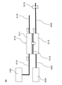
図1は、第1のモードを行っている、本開示のCO2分離システムの一部分の一例の模式図である。図1において明示されていないが、内燃機関は作動しており、かつ車両は走行している。 FIG. 1 is a schematic diagram of an example of a part of the CO 2 separation system of the present disclosure performing the first mode. Although not explicitly shown in FIG. 1, the internal combustion engine is operating and the vehicle is running.
図1において、内燃機関100から排出された排ガスは、矢印で示すように、第1のCO2供給側導入流路410を介して第1のCO2分離装置310のCO2供給側311に導入される。また、車両の外部200の空気は、矢印で示すように、走行風を動力として、第1のCO2透過側導入流路420を介して第1のCO2分離装置310のCO2透過側312に供給される。これにより、第1のCO2分離装置310のCO2供給側311には排ガスが存在し、かつCO2透過側312には空気が存在する。
In FIG. 1, the exhaust gas discharged from the
排ガス中のCO2の分圧は、空気中のCO2の分圧より高く、またベルヌーイの定理により、走行風によってCO2透過側においてCO2の静圧が低下しているので、第1のCO2分離置310のCO2供給側とCO2透過側とのCO2の分圧に差が生じる。 The partial pressure of CO 2 in the exhaust gas is higher than the partial pressure of CO 2 in the air, and according to Bernoulli's theorem, the static pressure of CO 2 is reduced on the CO 2 permeation side by the running wind. There is a difference in the partial pressure of CO 2 between the CO 2 supply side and the CO 2 permeation side of the CO 2 separation position 310.
この分圧の差を駆動力として、排ガス10中のCO2は、矢印で示すように、CO2透過膜313を介してCO2供給側311からCO2透過側312に透過する。 Using this difference in partial pressure as a driving force, CO 2 in the exhaust gas 10 permeates from the CO 2 supply side 311 to the CO 2 permeation side 312 via the CO 2 permeation membrane 313 as shown by an arrow.
CO2透過側312に透過したCO2は、矢印で示すように、第1のCO2透過側排出流路425を介して空気と共に第1のCO2分離装置310の外部に排出される。また、第1のCO2分離装置310のCO2供給側311に導入された排ガスの残りの成分は、矢印で示すように、第1のCO2供給側排出流路415を介して、第1のCO2分離装置310の外部に排出される。
As shown by the arrow, the CO 2 permeated through the CO 2 permeation side 312 is discharged to the outside of the first CO 2 separation device 310 together with air through the first CO 2 permeation side
なお、図1は、本開示のCO2分離システムを、第1のCO2供給側排出流路415及び第1のCO2透過側排出流路425を有する態様に限定する趣旨ではない。
Note that FIG. 1 is not intended to limit the CO 2 separation system of the present disclosure to an embodiment having a first CO 2 supply side
このように、第1のモードでは、第1のCO2分離装置のCO2供給側とCO2透過側とのCO2の分圧の差を利用することにより、CO2透過側において、CO2をより効率よく分離することができる。 As described above, in the first mode, CO 2 is used on the CO 2 permeation side by utilizing the difference in the partial pressure of CO 2 between the CO 2 supply side and the CO 2 permeation side of the first CO 2 separation device. Can be separated more efficiently.
〈第2のモード及び第3のモード〉
本開示のCO2分離システムは、車両の状態に応じて、更に以下の第2のモード及び第3のモードを行うことができる。
<Second mode and third mode>
The CO 2 separation system of the present disclosure can further perform the following second mode and third mode depending on the state of the vehicle.
(第2のモード)
本開示のCO2分離システムは、(B)内燃機関が作動しており、かつ車両が停止しているときに、第2のモードを行ってもよい。本開示のCO2分離システムが第2のモードを行う場合には、本開示のCO2分離システムは、第1の減圧装置を更に有している。
(Second mode)
The CO 2 separation system of the present disclosure may perform a second mode when (B) the internal combustion engine is operating and the vehicle is stopped. If the CO 2 separation system of the present disclosure performs a second mode, the CO 2 separation system of the present disclosure further comprises a first decompression device.
第2のモードは、第1のCO2供給側導入流路を介して第1のCO2分離装置のCO2供給側に、内燃機関から発生する排ガスを導入し、かつ第1のCO2分離装置のCO2透過側を第1の減圧装置によって減圧し、それによって、第1のCO2分離装置のCO2供給側とCO2透過側とのCO2の分圧の差を駆動力として、第1のCO2分離装置のCO2透過膜によって、排ガス中のCO2を、第1のCO2分離装置のCO2供給側からCO2透過側に選択的に透過させる。 In the second mode, the exhaust gas generated from the internal combustion engine is introduced into the CO 2 supply side of the first CO 2 separation device via the first CO 2 supply side introduction flow path, and the first CO 2 separation is performed. The CO 2 permeation side of the device is decompressed by the first decompression device, whereby the difference in the partial pressure of CO 2 between the CO 2 supply side and the CO 2 permeation side of the first CO 2 separation device is used as the driving force. The CO 2 permeation film of the first CO 2 separation device selectively permeates CO 2 in the exhaust gas from the CO 2 supply side of the first CO 2 separation device to the CO 2 permeation side.
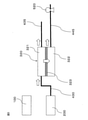
図2は、第2のモードを行っている、本開示のCO2分離システムの一部分の一例の模式図である。図2において明示されていないが、内燃機関は作動しており、かつ車両は停止している。 FIG. 2 is a schematic diagram of an example of a part of the CO 2 separation system of the present disclosure performing the second mode. Although not explicitly shown in FIG. 2, the internal combustion engine is operating and the vehicle is stopped.
図2において、内燃機関100から排出された排ガスは、矢印で示すように、第1のCO2分離装置310のCO2供給側311に導入される。また、第1のCO2分離装置310のCO2透過側312は、第1の減圧装置510によって減圧される。これにより、CO2供給側311とCO2透過側312との間にCO2の分圧の差が生じる。
In FIG. 2, the exhaust gas discharged from the
この分圧の差を駆動力として、排ガス中のCO2は、矢印で示すように、CO2透過膜313を介してCO2供給側311からCO2透過側312に透過する。 Using this difference in partial pressure as a driving force, CO 2 in the exhaust gas permeates from the CO 2 supply side 311 to the CO 2 permeation side 312 via the CO 2 permeation membrane 313 as shown by the arrow.
CO2透過側312は、第1のCO2透過側排出流路425に配置された第1の減圧装置510によって減圧されているため、CO2透過側312に透過したCO2は、矢印で示すように、第1のCO2透過側排出流路425を介して第1のCO2分離装置310の外部に効率よく排出される。また、第1のCO2分離装置310のCO2供給側311に導入された排ガスの残りの成分は、矢印で示すように、第1のCO2供給側排出流路415を介して第1のCO2分離装置310の外部に排出される。
Since the CO 2 permeation side 312 is decompressed by the
なお、図2は、本開示のCO2分離システムを、第1のCO2供給側排出流路415及び第1のCO2透過側排出流路425を有する態様に限定する趣旨ではない。また、図2は、本開示のCO2分離システムを、第1のCO2分離装置310の外部にCO2を排出するための動力を第1の減圧装置510によって与える態様に限定する趣旨ではない。
Note that FIG. 2 is not intended to limit the CO 2 separation system of the present disclosure to an embodiment having a first CO 2 supply side
このように、第2のモードでは、CO2分離装置のCO2供給側とCO2透過側とのCO2の分圧を利用することにより、CO2透過側において、CO2をより効率よく分離することができる。 As described above, in the second mode, CO 2 is separated more efficiently on the CO 2 permeation side by utilizing the partial pressure of CO 2 between the CO 2 supply side and the CO 2 permeation side of the CO 2 separation device. can do.
本開示のCO2分離システムが第1のモードに加えて第2のモードを行うことにより、内燃機関を動力として用いる車両における排ガス中のCO2をより効率よく分離することができる。 By performing the second mode in addition to the first mode, the CO 2 separation system of the present disclosure can more efficiently separate CO 2 in the exhaust gas in the vehicle using the internal combustion engine as the power source.
(第3のモード)
本開示のCO2分離システムは、更に(C)内燃機関が停止しているときに、第3のモードを行うことができる。本開示のCO2分離システムが第3のモードを行う場合には、CO2供給側及びCO2透過側を隔てているCO2透過膜を有する第2のCO2分離装置、車両の外部から空気を第2のCO2分離装置のCO2供給側に導入する第2のCO2供給側導入流路、及び第2のCO2分離装置のCO2透過側を減圧する第2の減圧装置を更に有している。
(Third mode)
The CO 2 separation system of the present disclosure can further (C) perform a third mode when the internal combustion engine is stopped. When the CO 2 separation system of the present disclosure performs the third mode, a second CO 2 separation device having a CO 2 permeation film separating the CO 2 supply side and the CO 2 permeation side, air from the outside of the vehicle. A second CO 2 supply side introduction flow path for introducing the carbon dioxide into the CO 2 supply side of the second CO 2 separation device, and a second decompression device for depressurizing the CO 2 permeation side of the second CO 2 separation device. Have.
第3のモードは、第2のCO2供給側導入流路を介して第2のCO2分離装置のCO2供給側に、車両の外部から空気を導入し、かつ第2のCO2分離装置のCO2透過側を第2の減圧装置によって減圧し、それによって、第2のCO2分離装置のCO2供給側とCO2透過側とのCO2の分圧の差を駆動力として、第2のCO2分離装置のCO2透過膜によって、空気中のCO2を、第2のCO2分離装置のCO2供給側からCO2透過側に選択的に透過させる。 In the third mode, air is introduced from the outside of the vehicle to the CO 2 supply side of the second CO 2 separation device via the second CO 2 supply side introduction flow path, and the second CO 2 separation device is used. The CO 2 permeation side of the carbon dioxide is decompressed by the second decompression device, whereby the difference in the partial pressure of CO 2 between the CO 2 supply side and the CO 2 permeation side of the second CO 2 separation device is used as a driving force. The CO 2 permeation film of the CO 2 separation device of 2 selectively permeates CO 2 in the air from the CO 2 supply side of the second CO 2 separation device to the CO 2 permeation side.
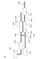
図3は、第3のモードを行っている、本開示のCO2分離システムの一部分の一例の模式図である。図3において明示されていないが、内燃機関は停止している。車両は、走行していても停止していてもよい。 FIG. 3 is a schematic diagram of an example of a part of the CO 2 separation system of the present disclosure performing the third mode. Although not explicitly shown in FIG. 3, the internal combustion engine is stopped. The vehicle may be running or stopped.
図3において、車両の外部200から導入された空気は、矢印で示すように、第2のCO2供給側導入流路430を介して第2のCO2分離装置320のCO2供給側321に導入される。また、第2のCO2分離装置320のCO2透過側322は、第2の減圧装置520によって減圧される。これにより、CO2供給側321とCO2透過側322との間においてCO2の分圧の差が生じる。
In FIG. 3, the air introduced from the outside 200 of the vehicle is sent to the CO 2 supply side 321 of the second CO 2 separation device 320 via the second CO 2 supply side
この分圧の差を駆動力として、空気中のCO2は、CO2透過膜323を介してCO2供給側321からCO2透過側322に透過する。 Using this difference in partial pressure as a driving force, CO 2 in the air permeates from the CO 2 supply side 321 to the CO 2 permeation side 322 via the CO 2 permeation membrane 323.
CO2透過側322は、第2のCO2透過側排出流路445に配置された第2の減圧装置520によって減圧されているため、CO2透過側322に透過したCO2は、矢印で示すように、第1のCO2透過側排出流路445を介して第2のCO2分離装置320の外部に効率よく排出される。また、CO2供給側321に導入された空気の残りの成分は、矢印で示すように、第2のCO2供給側排出流路435を介して第2のCO2分離装置320の外部に排出される。
Since the CO 2 permeation side 322 is decompressed by the
また、図3は、本開示のCO2分離システムが第2のCO2供給側排出流路435及び第2のCO2透過側排出流路445を有する態様に限定する趣旨ではない。また、図3は、本開示のCO2分離システムを、第2のCO2分離装置320の外部にCO2を排出するための動力を第2の減圧装置520によって与える態様に限定する趣旨ではない。
Further, FIG. 3 is not intended to be limited to an embodiment in which the CO 2 separation system of the present disclosure has a second CO 2 supply side
このように、第3のモードでは、CO2分離装置のCO2供給側とCO2透過側とのCO2の分圧を利用することにより、CO2透過側において、CO2をより効率よく分離することができる。 As described above, in the third mode, CO 2 is separated more efficiently on the CO 2 permeation side by utilizing the partial pressure of CO 2 between the CO 2 supply side and the CO 2 permeation side of the CO 2 separation device. can do.
また、本開示のCO2分離システムが第1のモードに加えて第3のモードを行うことにより、内燃機関を動力として用いる車両における排ガス中のCO2のみでなく、車道周辺の大気中のCO2も分離することができる。 Further, the CO 2 separation system of the present disclosure performs not only CO 2 in the exhaust gas in a vehicle using an internal combustion engine as a power source but also CO in the atmosphere around the roadway by performing a third mode in addition to the first mode. 2 can also be separated.
〈車両〉
本開示のCO2分離システムが搭載される車両は、内燃機関を動力として用いる車両である。本開示のCO2分離システムが搭載される車両は、電気モーターを更に有し、それによって内燃機関及び電気モーターの少なくとも一方を切り替えて動力として用いるハイブリッド車両であってよい。
<vehicle>
The vehicle equipped with the CO 2 separation system of the present disclosure is a vehicle that uses an internal combustion engine as power. The vehicle equipped with the CO 2 separation system of the present disclosure may be a hybrid vehicle that further has an electric motor, whereby at least one of an internal combustion engine and an electric motor is switched and used as power.
このようなハイブリッド車両に本開示のCO2分離システムを搭載する場合、車両の内燃機関が停止しており、電気モーターで車両が走行しているときにも、第3のモードを行うことが可能であり、車道周辺の大気中のCO2をより効率よく分離することができる。この場合、第2のCO2分離装置のCO2供給側とCO2透過側とのCO2の分圧の差は、第2の減圧装置による第2のCO2分離装置のCO2透過側の減圧に加えて、又はこれに代えて、ベルヌーイの定理により、走行風によってCO2透過側においてCO2の静圧を低下させることによっても生じさせることができる。 When the CO 2 separation system of the present disclosure is mounted on such a hybrid vehicle, the third mode can be performed even when the internal combustion engine of the vehicle is stopped and the vehicle is running by the electric motor. Therefore, CO 2 in the atmosphere around the roadway can be separated more efficiently. In this case, the difference in the partial pressure of CO 2 between the CO 2 supply side and the CO 2 permeation side of the second CO 2 separation device is the CO 2 permeation side of the second CO 2 separation device by the second decompression device. In addition to or instead of depressurization, it can also be caused by reducing the static pressure of CO 2 on the CO 2 permeation side by running wind, according to Bernoulli's theorem.
〈CO2分離装置〉
本開示のCO2分離システムは、第1のCO2分離装置を有する。第1のCO2分離装置は、CO2供給側及びCO2透過側を隔てているCO2透過膜を有する。
<CO 2 separation device>
The CO 2 separation system of the present disclosure has a first CO 2 separation device. The first CO 2 separator has a CO 2 permeation membrane that separates the CO 2 supply side and the CO 2 permeation side.
第1のCO2分離装置が有するCO2透過膜は、排ガス中からCO2を選択的に透過することができるものであれば、特に限定されない。第1及び第2のモードにおいてCO2透過膜を排ガスからCO2を分離させるために用いる観点からは、このCO2透過膜は、ゼオライト膜、又はシリカ膜等が好ましい。これらの透過膜は、機械的耐久性が高いためである。 The CO 2 permeation membrane included in the first CO 2 separation device is not particularly limited as long as it can selectively permeate CO 2 from the exhaust gas. From the viewpoint of using the CO 2 permeable membrane for separating CO 2 from the exhaust gas in the first and second modes, the CO 2 permeable membrane is preferably a zeolite membrane, a silica membrane, or the like. This is because these permeable membranes have high mechanical durability.
また、本開示のCO2分離システムが第3のモードを行う場合には、本開示のCO2分離システムは、第2のCO2分離装置を有する。第2のCO2分離装置は、CO2供給側及びCO2透過側を隔てているCO2透過膜を有する。 Further, when the CO 2 separation system of the present disclosure performs a third mode, the CO 2 separation system of the present disclosure has a second CO 2 separation device. The second CO 2 separator has a CO 2 permeation membrane that separates the CO 2 supply side and the CO 2 permeation side.
第2のCO2分離装置が有するCO2透過膜は、空気中からCO2を選択的に透過させることができるものであれば、特に限定されない。第3のモードにおいてCO2透過膜を空気からCO2を分離させるために用いる観点からは、このCO2透過膜は、高分子膜等、比較的分圧差が小さい場合でも高効率で分離できるものを用いることが好ましい。 The CO 2 permeation membrane included in the second CO 2 separation device is not particularly limited as long as it can selectively permeate CO 2 from the air. From the viewpoint of using the CO 2 permeable membrane for separating CO 2 from air in the third mode, this CO 2 permeable membrane can be separated with high efficiency even when the pressure difference is relatively small, such as a polymer membrane. It is preferable to use.
本開示のCO2分離システムが第1~第3のモードを行う場合において、第1のモード及び第2のモードにおいて用いられる第1のCO2分離装置と、第3のモードにおいて用いられる第2のCO2分離装置とは、別個のもの又は同一のものを利用することができる。この場合、CO2分離装置が有するCO2透過膜は、排ガス及び空気中からCO2を選択的に透過させることができるものが用いられる。 When the CO 2 separation system of the present disclosure performs the first to third modes, the first CO 2 separation device used in the first mode and the second mode and the second mode used in the third mode. A separate or identical CO 2 separator can be used. In this case, the CO 2 permeation membrane of the CO 2 separation device is used so that CO 2 can be selectively permeated from the exhaust gas and the air.
第1のモード及び第2のモードにおいて用いられる第1のCO2分離装置と、第3のモードにおいて用いられる第2のCO2分離装置とが別個である場合には、第1のモード及び第2のモードにおいて用いられる第1のCO2分離装置については排ガス中のCO2を透過させるのに適したCO2透過膜を用い、第3のモードにおいて用いられる第2のCO2分離装置については空気中のCO2を透過させるのに適したCO2透過膜をそれぞれ利用できる。そのため、CO2の透過に使用するCO2透過膜をモードに合わせてCO2透過膜を切り替えることができ、CO2分離を効率よく行うことができる。 If the first CO 2 separator used in the first mode and the second mode and the second CO 2 separator used in the third mode are separate, the first mode and the first mode. For the first CO 2 separation device used in the second mode, a CO 2 permeation film suitable for permeating CO 2 in the exhaust gas is used, and for the second CO 2 separation device used in the third mode. A CO 2 permeation film suitable for permeating CO 2 in the air can be used. Therefore, the CO 2 permeation membrane used for permeation of CO 2 can be switched according to the mode, and CO 2 separation can be efficiently performed.
また、第1のモード及び第2のモードにおいて用いられる第1のCO2分離装置と、第3のモードにおいて用いられる第2のCO2分離装置とが同一である場合には、本開示のCO2分離システムを搭載するために必要な空間を縮小することができ、本開示のCO2分離システムが搭載された車両の省スペース化が可能である。 Further, when the first CO 2 separation device used in the first mode and the second mode and the second CO 2 separation device used in the third mode are the same, the CO of the present disclosure is used. The space required for mounting the two -separation system can be reduced, and the space of the vehicle equipped with the CO 2 separation system of the present disclosure can be saved.
〈流路〉
本開示のCO2分離システムは、内燃機関から生じる排ガスを第1のCO2分離装置のCO2供給側に導入する第1のCO2供給側導入流路、及び車両の外部から空気を第1のCO2分離装置のCO2透過側に導入する第1のCO2透過側導入流路を有する。
<Flow path>
In the CO 2 separation system of the present disclosure, the exhaust gas generated from the internal combustion engine is introduced into the CO 2 supply side of the first CO 2 separation device, the first CO 2 supply side introduction flow path, and the air from the outside of the vehicle is first. It has a first CO 2 permeation side introduction flow path to be introduced to the CO 2 permeation side of the CO 2 permeation device.
第1のCO2供給側導入流路は、内燃機関から生じる排ガスを第1のCO2分離装置のCO2供給側に導入することができるものであれば、形態は特に限定されない。第1のCO2供給側導入流路は、例えば内燃機関と第1のCO2分離装置のCO2供給側とを連通する配管の形態を有していることができる。 The form of the first CO 2 supply side introduction flow path is not particularly limited as long as it can introduce the exhaust gas generated from the internal combustion engine to the CO 2 supply side of the first CO 2 separation device. The first CO 2 supply side introduction flow path can have, for example, a form of a pipe communicating the internal combustion engine and the CO 2 supply side of the first CO 2 separation device.
第1のCO2透過側導入流路は、車両の外部の空気を第1のCO2分離装置のCO2透過側に導入することができるものであれば、形態は特に限定されない。第1のCO2透過側導入流路は、例えば車両の外部と第1のCO2分離装置のCO2透過側とを連通する配管の形態を有していることができる。 The form of the first CO 2 permeation side introduction channel is not particularly limited as long as it can introduce the air outside the vehicle to the CO 2 permeation side of the first CO 2 separation device. The first CO 2 permeation side introduction flow path can have, for example, a form of a pipe that communicates the outside of the vehicle with the CO 2 permeation side of the first CO 2 separation device.
本開示のCO2分離システムにおいて、第3のモードを行う場合には、CO2分離システムは、車両の外部から空気を第2のCO2分離装置のCO2供給側に導入する第2のCO2供給側導入流路を有する。 In the CO 2 separation system of the present disclosure, when the third mode is performed, the CO 2 separation system introduces air from the outside of the vehicle to the CO 2 supply side of the second CO 2 separation device. 2 It has a supply side introduction flow path.
第2のCO2供給側導入流路は、車両の外部の空気を第2のCO2分離装置のCO2供給側に導入することができるものであれば、形態は特に限定されない。第2のCO2供給側導入流路は、例えば車両の外部と第2のCO2分離装置のCO2供給側とを連通する配管の形態を有していることができる。 The form of the second CO 2 supply side introduction flow path is not particularly limited as long as it can introduce the air outside the vehicle to the CO 2 supply side of the second CO 2 separation device. The second CO 2 supply side introduction flow path can have, for example, a form of a pipe that communicates the outside of the vehicle with the CO 2 supply side of the second CO 2 separation device.
第1のモード及び第2のモードにおいて用いられる第1のCO2分離装置と、第3のモードにおいて用いられる第2のCO2分離装置とが同一である場合には、第1のCO2供給側導入流路と、第2のCO2供給側導入流路とは同一であって良い。 If the first CO 2 separator used in the first mode and the second mode and the second CO 2 separator used in the third mode are the same, the first CO 2 supply The side introduction flow path and the second CO 2 supply side introduction flow path may be the same.
第1のCO2供給側導入流路と、第2のCO2供給側導入流路とが同一の場合、CO2供給側導入流路は、例えばCO2分離装置側の反対側において枝分かれした配管構造を有していることができる。この枝分かれした配管の一方が内燃機関とCO2分離装置とを連通し、かつ他方の配管が車両の外部とCO2分離装置とを連通させた構造を有していてもよい。 When the first CO 2 supply side introduction flow path and the second CO 2 supply side introduction flow path are the same, the CO 2 supply side introduction flow path is, for example, a branching pipe on the opposite side of the CO 2 separation device side. Can have a structure. One of the branched pipes may have a structure in which the internal combustion engine and the CO 2 separation device are communicated with each other, and the other pipe may have a structure in which the outside of the vehicle and the CO 2 separation device are communicated with each other.
さらに、この枝分かれした配管のうち車両の外部とCO2分離装置とを連通している配管にバルブ等の切替装置が設けられ、モードに応じてCO2分離装置のCO2供給側に導入する気体を切り替えることができる構造を有していてもよい。 Further, among the branched pipes, a switching device such as a valve is provided in the pipe connecting the outside of the vehicle and the CO 2 separation device, and the gas to be introduced to the CO 2 supply side of the CO 2 separation device according to the mode. It may have a structure capable of switching.
〈減圧装置〉
本開示のCO2分離システムにおいて、第2及び第3のモードを行う場合には、CO2分離システムはそれぞれ第1及び第2の減圧装置を有する。減圧装置は、公知のものを用いることができる。減圧装置としては、例えば減圧ポンプを挙げることができる。
<Decompression device>
In the CO 2 separation system of the present disclosure, when the second and third modes are performed, the CO 2 separation system has a first and a second decompression device, respectively. As the depressurizing device, a known one can be used. Examples of the decompression device include a decompression pump.
減圧装置は、第2及び第3のモードを行う際に、CO2分離装置のCO2透過側を減圧するために用いられる。また、減圧装置は、CO2透過側に透過したCO2を、CO2分離装置の外部に排出するための動力として用いることができる。 The decompression device is used to depressurize the CO 2 permeation side of the CO 2 separation device when performing the second and third modes. Further, the decompression device can be used as a power for discharging CO 2 transmitted to the CO 2 permeation side to the outside of the CO 2 separation device.
第1の減圧装置と第2の減圧装置とは、同一又は別個のものであってよい。 The first decompression device and the second decompression device may be the same or separate.
《構成例》
本開示のCO2分離システムは、例えば以下に示すような構成を有することができる。なお、これらの構成は、本開示のCO2分離システムの態様を限定するものではない。
<< Configuration example >>
The CO 2 separation system of the present disclosure can have, for example, the configuration shown below. It should be noted that these configurations do not limit the mode of the CO 2 separation system of the present disclosure.
〈構成例1〉
図4は、第1のモード、第2のモード及び第3のモードを行うことができる、本開示のCO2分離システムの他の例の概略図である。
<Structure example 1>
FIG. 4 is a schematic diagram of another example of the CO 2 separation system of the present disclosure capable of performing a first mode, a second mode and a third mode.
図4において、CO2分離システムは、内燃機関100、第1のCO2分離装置310、第1のCO2供給側導入流路410、第1のCO2透過側導入流路420、第2のCO2分離装置320、第2のCO2供給側導入流路430、及び減圧装置500を有する。
In FIG. 4, the CO 2 separation system includes an
ここで、第1のCO2分離装置310は、CO2供給側及311及びCO2透過側312を隔てているCO2透過膜313を有する。また、第2のCO2分離装置320は、CO2供給側及321及びCO2透過側322を隔てているCO2透過膜323を有する。 Here, the first CO 2 separation device 310 has a CO 2 permeation membrane 313 that separates the CO 2 supply side and 311 and the CO 2 permeation side 312. Further, the second CO 2 separation device 320 has a CO 2 permeation membrane 323 that separates the CO 2 supply side 321 and the CO 2 permeation side 322.
第1のCO2供給側導入流路410は、内燃機関100と第1のCO2分離装置のCO2供給側311とを連通している。また、第1のCO2透過側導入流路420は、車両の外部200と第1のCO2分離装置310のCO2透過側312とを連通している。また、第2のCO2供給側導入流路430は、車両の外部200と第2のCO2分離装置320のCO2供給側321とを連通している。
The first CO 2 supply side
ここで、図4において、CO2分離システムは、更に第1のCO2透過側導入流路420の第1のCO2分離装置310側の反対側に、車両の外部200からの空気の導入量を調節可能なバルブ801が設けられている。また、第2のCO2供給側導入流路430の第2のCO2分離装置320側の反対側に、車両の外部200からの空気の導入量を調節可能なバルブ802が設けられている。
Here, in FIG. 4, the CO 2 separation system further introduces air from the outside 200 of the vehicle to the opposite side of the first CO 2 permeation side
また、図4において、CO2分離システムは、更に排ガス浄化用触媒装置600、第1のCO2供給側排出流路415、第1のCO2透過側排出流路425、第2のCO2供給側排出流路435、第2のCO2透過側排出流路445、及びCO2貯蔵装置700を有する。
Further, in FIG. 4, the CO 2 separation system further includes an exhaust gas
図4のCO2分離システムにおいて、第1のモードを行った場合、本開示のCO2分離システムは、次のように機能する。 In the CO 2 separation system of FIG. 4, when the first mode is performed, the CO 2 separation system of the present disclosure functions as follows.
内燃機関100から発生した排ガスは、排ガス浄化用触媒装置600を通過した後、第1のCO2供給側導入流路410を介して第1のCO2分離装置310のCO2供給側311に導入される。また、バルブ801は開かれており、車両の外部200の空気は、例えば走行風によって車両内に取り入れられ、第1のCO2透過側導入流路420を介して第1のCO2分離装置310のCO2透過側312に供給される。
The exhaust gas generated from the
これにより、第1のCO2分離装置310のCO2供給側311には排ガスが、かつCO2透過側312には空気が導入され、第1のCO2分離装置310のCO2供給側311とCO2透過側312との間にCO2の分圧が生じる。 As a result, exhaust gas is introduced into the CO 2 supply side 311 of the first CO 2 separation device 310, and air is introduced into the CO 2 permeation side 312 to the CO 2 supply side 311 of the first CO 2 separation device 310. A partial pressure of CO 2 is generated between the CO 2 permeation side and 312.
この分圧の差を駆動力として、排ガス中のCO2は、CO2透過膜313を介してCO2供給側311からCO2透過側312に透過する。 Using this difference in partial pressure as a driving force, CO 2 in the exhaust gas permeates from the CO 2 supply side 311 to the CO 2 permeation side 312 via the CO 2 permeation membrane 313.
CO2透過側312に透過したCO2は、第1のCO2透過側排出流路425を介して空気と共に第1のCO2分離装置310の外部に排出され、CO2貯蔵装置700において貯蔵される。
The CO 2 permeated through the CO 2 permeation side 312 is discharged to the outside of the first CO 2 separation device 310 together with air through the first CO 2 permeation side
図4のシステムを用いて、第2のモードを行った場合、本開示のCO2分離システムは、次のように機能する。 When the second mode is performed using the system of FIG. 4, the CO 2 separation system of the present disclosure functions as follows.
内燃機関100から発生した排ガスは、排ガス浄化用触媒装置600を通過した後、第1のCO2供給側導入流路410を介して第1のCO2分離装置310のCO2供給側311に導入される。ここで、バルブ801は閉じている。
The exhaust gas generated from the
第1のCO2分離装置310のCO2透過側312は、減圧装置500によって減圧される。これにより、第1のCO2分離装置310のCO2供給側311とCO2透過側312との間にCO2の分圧が生じる。
The CO 2 permeation side 312 of the first CO 2 separation device 310 is decompressed by the
この分圧の差を駆動力として、排ガス中のCO2は、CO2透過膜313を介してCO2供給側311からCO2透過側312に透過する。 Using this difference in partial pressure as a driving force, CO 2 in the exhaust gas permeates from the CO 2 supply side 311 to the CO 2 permeation side 312 via the CO 2 permeation membrane 313.
CO2透過側312に透過したCO2は、第1のCO2透過側排出流路425を介して空気と共に第1のCO2分離装置310の外部に排出され、CO2貯蔵装置700において貯蔵される。
The CO 2 permeated through the CO 2 permeation side 312 is discharged to the outside of the first CO 2 separation device 310 together with air through the first CO 2 permeation side
図4のCO2分離システムを用いて、第3のモードを行った場合、本開示のCO2分離システムは、次のように機能する。 When the third mode is performed using the CO 2 separation system of FIG. 4, the CO 2 separation system of the present disclosure functions as follows.
第2のCO2供給側導入流路430の第2のCO2分離装置320の反対側に設けられているバルブ802は開かれており、これによって第2のCO2供給側導入流路430を介して車両の外部200から第2のCO2分離装置320のCO2供給側321に空気が導入される。また、減圧装置500によって第2のCO2分離装置320のCO2透過側322は、減圧される。
The
これにより、第2のCO2分離装置320のCO2供給側321とCO2透過側322との間におけるCO2の分圧に差が生じる。この分圧の差を駆動力として、空気のCO2は、CO2透過膜323を介してCO2供給側321からCO2透過側322に透過する。CO2透過側322に透過したCO2は、第2のCO2透過側排出流路445を介して第2のCO2分離装置320の外部に排出され、CO2貯蔵装置700において貯蔵される。
This causes a difference in the partial pressure of CO 2 between the CO 2 supply side 321 and the CO 2 permeation side 322 of the second CO 2 separation device 320. Using this difference in partial pressure as a driving force, CO 2 of air permeates from the CO 2 supply side 321 to the CO 2 permeation side 322 via the CO 2 permeation membrane 323. The CO 2 permeated through the CO 2 permeation side 322 is discharged to the outside of the second CO 2 separation
〈構成例2〉
図5は、第1のモード、第2のモード及び第3のモードを行うことができる、本開示のCO2分離システムの他の一例の概略図である。
<Structure example 2>
FIG. 5 is a schematic diagram of another example of the CO 2 separation system of the present disclosure capable of performing a first mode, a second mode and a third mode.
図5のCO2分離システムは、第1のCO2分離装置と、第2のCO2分離装置とが同一であり、第1のCO2供給側導入流路と、第2のCO2供給側導入流路とが同一であり、かつ第1の減圧装置と、第2の減圧装置とが同一である構成を有している。 In the CO 2 separation system of FIG. 5, the first CO 2 separation device and the second CO 2 separation device are the same, the first CO 2 supply side introduction flow path and the second CO 2 supply side. It has the same structure as the introduction flow path, and the first decompression device and the second decompression device are the same.
図5において、CO2分離システムは、内燃機関100、第1のCO2分離装置310、第1のCO2供給側導入流路410、第1のCO2透過側導入流路420、及び減圧装置500を有する。
In FIG. 5, the CO 2 separation system includes an
ここで、第1のCO2分離装置310は、CO2供給側311及びCO2透過側312を隔てているCO2透過膜323を有する。第1のCO2供給側導入流路410は、内燃機関100と第1のCO2分離装置310のCO2供給側311とを連通しており、かつ車両の外部200と第1のCO2分離装置310のCO2供給側311とを連通している。また、第1のCO2透過側導入流路420は、車両の外部200と第1のCO2分離装置310のCO2透過側312とを連通している。
Here, the first CO 2 separation device 310 has a CO 2 permeation membrane 323 that separates the CO 2 supply side 311 and the CO 2 permeation side 312. The first CO 2 supply side
さらに、第1のCO2供給側導入流路410の車両の外部200側、及び第1のCO2透過側導入流路420の車両の外部200側には、それぞれバルブ801及びバルブ802が設けられている。この2つのバルブの開閉により、車両の外部200の空気を、第1のCO2分離装置310のCO2供給側311及びCO2透過側312に切り替えて導入することができる。
Further,
また、図5において、CO2分離システムは、更に排ガス浄化用触媒装置600、第1のCO2供給側排出流路415、第1のCO2透過側排出流路425、及びCO2貯蔵装置700を有する。ここで、減圧装置500は、第1のCO2透過側排出流路425の第1のCO2分離装置310の反対側に設けられている。
Further, in FIG. 5, the CO 2 separation system further includes an exhaust gas
図5のCO2分離システムは、図4のCO2分離システムと同様に、内燃機関が作動しているか停止しているか否か、及び車両が走行しているか否かに応じてバルブ801及びバルブ802の開閉により、第1のモード、第2のモード及び第3のモードを行うことができる。
The CO 2 separation system of FIG. 5, like the CO 2 separation system of FIG. 4, has
100 内燃機関
200 車両の外部
310 第1のCO2分離装置
311 CO2供給側
312 CO2透過側
313 CO2透過膜
320 第2のCO2分離装置
321 CO2供給側
322 CO2透過側
323 CO2透過膜
410 第1のCO2供給側導入流路
415 第1のCO2供給側排出流路
420 第1のCO2透過側導入流路
425 第1のCO2透過側排出流路
430 第2のCO2供給側導入流路
435 第2のCO2供給側排出流路
445 第2のCO2透過側排出流路
500 減圧装置
510 第1の減圧装置
520 第2の減圧装置
600 排ガス浄化用触媒装置
700 CO2貯蔵装置
801 バルブ
802 バルブ
100
Claims (5)
内燃機関、
CO2供給側及びCO2透過側を隔てているCO2透過膜を有する第1のCO2分離装置、
前記内燃機関から生じる排ガスを前記第1のCO2分離装置のCO2供給側に導入する第1のCO2供給側導入流路、
前記車両の外部から空気を前記第1のCO2分離装置のCO2透過側に導入する第1のCO2透過側導入流路、及び
前記第1のCO 2 分離装置のCO 2 透過側を減圧する第1の減圧装置
を有しており、
(A)前記内燃機関が作動しており、かつ前記車両が走行しているときに、
前記第1のCO2供給側導入流路を介して前記CO2分離装置のCO2供給側に、前記内燃機関から発生する排ガスを導入し、かつ前記第1のCO2透過側導入流路を介して前記第1のCO2分離装置のCO2透過側に、走行風を利用して前記車両の外部から空気を導入し、それによって、前記第1のCO2分離装置のCO2供給側とCO2透過側とのCO2の分圧の差を駆動力として、前記第1のCO2分離装置のCO2透過膜によって、前記排ガス中のCO2を、前記第1のCO2分離装置のCO2供給側からCO2透過側に選択的に透過させる、第1のモードを行い、
(B)前記内燃機関が作動しており、かつ前記車両が停止しているときに、
前記第1のCO 2 供給側導入流路を介して前記第1のCO 2 分離装置のCO 2 供給側に、前記内燃機関から発生する排ガスを導入し、かつ前記第1のCO 2 分離装置のCO 2 透過側を前記第1の減圧装置によって減圧し、それによって、前記第1のCO 2 分離装置のCO 2 供給側とCO 2 透過側とのCO 2 の分圧の差を駆動力として、前記第1のCO 2 分離装置のCO 2 透過膜によって、前記排ガス中のCO 2 を、前記第1のCO 2 分離装置のCO 2 供給側からCO 2 透過側に選択的に透過させる、第2のモードを行う、
CO2分離システム。 A CO 2 separation system for mounting on vehicles that use an internal combustion engine as a power source.
Internal combustion engine,
A first CO 2 separator having a CO 2 permeation membrane separating a CO 2 supply side and a CO 2 permeation side,
A first CO 2 supply side introduction flow path for introducing exhaust gas generated from the internal combustion engine to the CO 2 supply side of the first CO 2 separation device ,
A first CO 2 permeation side introduction flow path that introduces air from the outside of the vehicle to the CO 2 permeation side of the first CO 2 separation device , and
A first decompression device that decompresses the CO 2 permeation side of the first CO 2 separation device.
Have and
(A) When the internal combustion engine is operating and the vehicle is running
The exhaust gas generated from the internal combustion engine is introduced into the CO 2 supply side of the CO 2 separation device via the first CO 2 supply side introduction flow path, and the first CO 2 permeation side introduction flow path is introduced. Air is introduced from the outside of the vehicle to the CO 2 permeation side of the first CO 2 separation device via the traveling wind, thereby the CO 2 supply side of the first CO 2 separation device. Using the difference in the partial pressure of CO 2 from the CO 2 permeation side as a driving force, the CO 2 in the exhaust gas is transferred to the CO 2 separation device of the first CO 2 separation device by the CO 2 permeation film of the first CO 2 separation device. Perform the first mode of selectively transmitting from the CO 2 supply side to the CO 2 transmission side.
(B) When the internal combustion engine is operating and the vehicle is stopped.
The exhaust gas generated from the internal combustion engine is introduced into the CO 2 supply side of the first CO 2 separation device via the first CO 2 supply side introduction flow path, and the first CO 2 separation device is used. The CO 2 permeation side is decompressed by the first decompression device, whereby the difference in the partial pressure of CO 2 between the CO 2 supply side and the CO 2 permeation side of the first CO 2 separation device is used as a driving force. A second CO 2 permeation film that selectively permeates CO 2 in the exhaust gas from the CO 2 supply side to the CO 2 permeation side of the first CO 2 separation device . Do the mode,
CO 2 separation system.
前記車両の外部から空気を前記第2のCO2分離装置のCO2供給側に導入する第2のCO2供給側導入流路、及び
前記第2のCO2分離装置のCO2透過側を減圧する第2の減圧装置を更に有しており、
(C)前記内燃機関が停止しているときに、
前記第2のCO2供給側導入流路を介して前記第2のCO2分離装置のCO2供給側に、前記車両の外部から空気を導入し、かつ前記第2のCO2分離装置のCO2透過側を前記第2の減圧装置によって減圧し、それによって、前記第2のCO2分離装置のCO2供給側とCO2透過側とのCO2の分圧の差を駆動力として、前記第2のCO2分離装置のCO2透過膜によって、前記空気中のCO2を、前記第2のCO2分離装置のCO2供給側からCO2透過側に選択的に透過させる、第3のモードを行う、
請求項1に記載のシステム。 A second CO 2 separator having a CO 2 permeation membrane separating the CO 2 supply side and the CO 2 permeation side,
The second CO 2 supply side introduction flow path for introducing air from the outside of the vehicle to the CO 2 supply side of the second CO 2 separation device and the CO 2 permeation side of the second CO 2 separation device are depressurized. It also has a second decompression device to
(C) When the internal combustion engine is stopped
Air is introduced from the outside of the vehicle to the CO 2 supply side of the second CO 2 separation device via the second CO 2 supply side introduction flow path, and the CO of the second CO 2 separation device is used. The 2 permeation side is decompressed by the second decompression device, whereby the difference in the partial pressure of CO 2 between the CO 2 supply side and the CO 2 permeation side of the second CO 2 separation device is used as a driving force. A third CO 2 permeation film that selectively permeates CO 2 in the air from the CO 2 supply side to the CO 2 permeation side of the second CO 2 separation device. Do the mode,
The system according to claim 1 .
内燃機関、
CO 2 供給側及びCO 2 透過側を隔てているCO 2 透過膜を有する第1のCO 2 分離装置、
前記内燃機関から生じる排ガスを前記第1のCO 2 分離装置のCO 2 供給側に導入する第1のCO 2 供給側導入流路、
前記車両の外部から空気を前記第1のCO 2 分離装置のCO 2 透過側に導入する第1のCO 2 透過側導入流路、
前記第1のCO2分離装置のCO2透過側を減圧する第1の減圧装置、
CO2供給側及びCO2透過側を隔てているCO2透過膜を有する第2のCO2分離装置、
前記車両の外部から空気を前記第2のCO2分離装置のCO2供給側に導入する第2のCO2供給側導入流路、及び
前記第2のCO2分離装置のCO2透過側を減圧する第2の減圧装置
を有しており、
(A)前記内燃機関が作動しており、かつ前記車両が走行しているときに、
前記第1のCO 2 供給側導入流路を介して前記CO 2 分離装置のCO 2 供給側に、前記内燃機関から発生する排ガスを導入し、かつ前記第1のCO 2 透過側導入流路を介して前記第1のCO 2 分離装置のCO 2 透過側に、走行風を利用して前記車両の外部から空気を導入し、それによって、前記第1のCO 2 分離装置のCO 2 供給側とCO 2 透過側とのCO 2 の分圧の差を駆動力として、前記第1のCO 2 分離装置のCO 2 透過膜によって、前記排ガス中のCO 2 を、前記第1のCO 2 分離装置のCO 2 供給側からCO 2 透過側に選択的に透過させる、第1のモードを行い、
(B)前記内燃機関が作動しており、かつ前記車両が停止しているときに、
前記第1のCO2供給側導入流路を介して前記第1のCO2分離装置のCO2供給側に、前記内燃機関から発生する排ガスを導入し、かつ前記第1のCO2分離装置のCO2透過側を前記第1の減圧装置によって減圧し、それによって、前記第1のCO2分離装置のCO2供給側とCO2透過側とのCO2の分圧の差を駆動力として、前記第1のCO2分離装置のCO2透過膜によって、前記排ガス中のCO2を、前記第1のCO2分離装置のCO2供給側からCO2透過側に選択的に透過させる、第2のモードを行い、
(C)前記内燃機関が停止しているときに、
前記第2のCO2供給側導入流路を介して前記第2のCO2分離装置のCO2供給側に、前記車両の外部から空気を導入し、かつ前記第2のCO2分離装置のCO2透過側を前記第2の減圧装置によって減圧し、それによって、前記第2のCO2分離装置のCO2供給側とCO2透過側とのCO2の分圧の差を駆動力として、前記第2のCO2分離装置のCO2透過膜によって、前記空気中のCO2を、前記第2のCO2分離装置のCO2供給側からCO2透過側に選択的に透過させる、第3のモードを行う、
CO 2 分離システム。 A CO 2 separation system for mounting on vehicles that use an internal combustion engine as a power source .
Internal combustion engine,
A first CO 2 separator having a CO 2 permeation membrane separating a CO 2 supply side and a CO 2 permeation side ,
A first CO 2 supply side introduction flow path for introducing exhaust gas generated from the internal combustion engine to the CO 2 supply side of the first CO 2 separation device ,
A first CO 2 permeation side introduction flow path that introduces air from the outside of the vehicle to the CO 2 permeation side of the first CO 2 separation device ,
A first decompression device that decompresses the CO 2 permeation side of the first CO 2 separation device,
A second CO 2 separator having a CO 2 permeation membrane separating the CO 2 supply side and the CO 2 permeation side,
The second CO 2 supply side introduction flow path for introducing air from the outside of the vehicle to the CO 2 supply side of the second CO 2 separation device and the CO 2 permeation side of the second CO 2 separation device are depressurized. Second decompression device
Have and
(A) When the internal combustion engine is operating and the vehicle is running
The exhaust gas generated from the internal combustion engine is introduced into the CO 2 supply side of the CO 2 separation device via the first CO 2 supply side introduction flow path , and the first CO 2 permeation side introduction flow path is introduced. Air is introduced from the outside of the vehicle to the CO 2 permeation side of the first CO 2 separation device via the traveling wind, thereby the CO 2 supply side of the first CO 2 separation device. Using the difference in the partial pressure of CO 2 from the CO 2 permeation side as a driving force, the CO 2 in the exhaust gas is transferred to the CO 2 separation device of the first CO 2 separation device by the CO 2 permeation film of the first CO 2 separation device. Perform the first mode of selectively transmitting from the CO 2 supply side to the CO 2 transmission side.
(B) When the internal combustion engine is operating and the vehicle is stopped.
The exhaust gas generated from the internal combustion engine is introduced into the CO 2 supply side of the first CO 2 separation device via the first CO 2 supply side introduction flow path, and the first CO 2 separation device is used. The CO 2 permeation side is decompressed by the first decompression device, whereby the difference in the partial pressure of CO 2 between the CO 2 supply side and the CO 2 permeation side of the first CO 2 separation device is used as a driving force. A second CO 2 permeation film that selectively permeates CO 2 in the exhaust gas from the CO 2 supply side to the CO 2 permeation side of the first CO 2 separation device . Mode,
(C) When the internal combustion engine is stopped
Air is introduced from the outside of the vehicle to the CO 2 supply side of the second CO 2 separation device via the second CO 2 supply side introduction flow path, and the CO of the second CO 2 separation device is used. The 2 permeation side is decompressed by the second decompression device, whereby the difference in the partial pressure of CO 2 between the CO 2 supply side and the CO 2 permeation side of the second CO 2 separation device is used as a driving force. A third CO 2 permeation film that selectively permeates CO 2 in the air from the CO 2 supply side to the CO 2 permeation side of the second CO 2 separation device. Do the mode,
CO 2 separation system.
前記第1のCO2供給側導入流路は、前記第2のCO2供給側導入流路を兼ねており、かつ
前記第1の減圧装置は、前記第2の減圧装置を兼ねている、請求項3に記載のシステム。 The first CO 2 separation device also serves as the second CO 2 separation device.
The first CO 2 supply side introduction flow path also serves as the second CO 2 supply side introduction flow path, and the first decompression device also serves as the second decompression device. Item 3. The system according to item 3.
Priority Applications (4)
| Application Number | Priority Date | Filing Date | Title |
|---|---|---|---|
| JP2018117315A JP6996432B2 (en) | 2018-06-20 | 2018-06-20 | CO2 separation system for mounting on vehicles that use an internal combustion engine as power |
| US16/390,032 US10894230B2 (en) | 2018-06-20 | 2019-04-22 | CO2 separation system for installation in vehicle using internal combustion engine as power source |
| DE102019111289.3A DE102019111289A1 (en) | 2018-06-20 | 2019-05-02 | CO2 SEPARATION SYSTEM FOR INSTALLATION IN A VEHICLE USING A COMBUSTION ENGINE AS AN ENERGY SOURCE |
| CN201910392372.6A CN110617125B (en) | 2018-06-20 | 2019-05-13 | CO for mounting on vehicle using internal combustion engine as power2Separation system |
Applications Claiming Priority (1)
| Application Number | Priority Date | Filing Date | Title |
|---|---|---|---|
| JP2018117315A JP6996432B2 (en) | 2018-06-20 | 2018-06-20 | CO2 separation system for mounting on vehicles that use an internal combustion engine as power |
Publications (2)
| Publication Number | Publication Date |
|---|---|
| JP2019217465A JP2019217465A (en) | 2019-12-26 |
| JP6996432B2 true JP6996432B2 (en) | 2022-02-04 |
Family
ID=68805972
Family Applications (1)
| Application Number | Title | Priority Date | Filing Date |
|---|---|---|---|
| JP2018117315A Expired - Fee Related JP6996432B2 (en) | 2018-06-20 | 2018-06-20 | CO2 separation system for mounting on vehicles that use an internal combustion engine as power |
Country Status (4)
| Country | Link |
|---|---|
| US (1) | US10894230B2 (en) |
| JP (1) | JP6996432B2 (en) |
| CN (1) | CN110617125B (en) |
| DE (1) | DE102019111289A1 (en) |
Families Citing this family (6)
| Publication number | Priority date | Publication date | Assignee | Title |
|---|---|---|---|---|
| EP3858468A1 (en) | 2020-02-03 | 2021-08-04 | Basf Se | Process and absorption unit for removal of co2 from vehicle exhaust gas |
| JP7160062B2 (en) * | 2020-03-23 | 2022-10-25 | トヨタ自動車株式会社 | CO2 separation system |
| EP4301491A4 (en) * | 2021-03-04 | 2024-11-20 | Echeneidae Inc. | SYSTEM AND METHOD FOR MOBILE CARBON SEPARATION |
| FR3120654B1 (en) * | 2021-03-11 | 2026-04-17 | Renault Sas | Replaceable on-board carbon dioxide capture system for internal combustion engines |
| JP7831015B2 (en) * | 2022-03-04 | 2026-03-17 | 富士電機株式会社 | Exhaust gas treatment equipment |
| US20250043707A1 (en) * | 2023-08-02 | 2025-02-06 | Faurecia Emissions Control Technologies, Usa, Llc | Method and apparatus for carbon capture in an exhaust system |
Citations (4)
| Publication number | Priority date | Publication date | Assignee | Title |
|---|---|---|---|---|
| JP2007113459A (en) | 2005-10-19 | 2007-05-10 | Toyota Motor Corp | Exhaust gas purification system |
| JP2010024923A (en) | 2008-07-17 | 2010-02-04 | Toyota Motor Corp | Exhaust gas purifying device for hybrid vehicle, and purifying method |
| JP2010203419A (en) | 2009-03-06 | 2010-09-16 | Toyota Motor Corp | Exhaust emission control device for hybrid vehicle |
| US20170183996A1 (en) | 2010-09-13 | 2017-06-29 | Membrane Technology And Research, Inc. | Gas Separation Process Using Membranes with Permeate Sweep to Remove CO2 from Combustion Exhaust |
Family Cites Families (8)
| Publication number | Priority date | Publication date | Assignee | Title |
|---|---|---|---|---|
| CN100416056C (en) * | 2005-08-17 | 2008-09-03 | 株式会社电装 | Exhaust gas cleaning device and its method |
| JP2007292010A (en) * | 2006-04-27 | 2007-11-08 | Toyota Motor Corp | Purification of exhaust gas containing nitrogen oxides exhausted from internal combustion engines |
| CN101792139A (en) * | 2010-02-02 | 2010-08-04 | 黄道军 | Method for recovering CO2 |
| US9457313B2 (en) * | 2010-09-13 | 2016-10-04 | Membrane Technology And Research, Inc. | Membrane technology for use in a power generation process |
| WO2013063052A1 (en) | 2011-10-24 | 2013-05-02 | Saudi Arabian Oil Company | Emission reduction from mobile sources by on-board carbon dioxide conversion to fuel |
| US9488100B2 (en) | 2012-03-22 | 2016-11-08 | Saudi Arabian Oil Company | Apparatus and method for oxy-combustion of fuels in internal combustion engines |
| DE102012213037A1 (en) * | 2012-07-25 | 2014-01-30 | Siemens Aktiengesellschaft | Storage device for storing electrical energy, preferably e.g. battery, comprises first and second electrode, electrolyte layer comprising electrolytic fluid permeable to carbonate, and reservoir for ion transported through electrolyte layer |
| US9598993B2 (en) * | 2015-06-19 | 2017-03-21 | Saudi Arabian Oil Company | Integrated process for CO2 capture and use in thermal power production cycle |
-
2018
- 2018-06-20 JP JP2018117315A patent/JP6996432B2/en not_active Expired - Fee Related
-
2019
- 2019-04-22 US US16/390,032 patent/US10894230B2/en not_active Expired - Fee Related
- 2019-05-02 DE DE102019111289.3A patent/DE102019111289A1/en not_active Withdrawn
- 2019-05-13 CN CN201910392372.6A patent/CN110617125B/en not_active Expired - Fee Related
Patent Citations (4)
| Publication number | Priority date | Publication date | Assignee | Title |
|---|---|---|---|---|
| JP2007113459A (en) | 2005-10-19 | 2007-05-10 | Toyota Motor Corp | Exhaust gas purification system |
| JP2010024923A (en) | 2008-07-17 | 2010-02-04 | Toyota Motor Corp | Exhaust gas purifying device for hybrid vehicle, and purifying method |
| JP2010203419A (en) | 2009-03-06 | 2010-09-16 | Toyota Motor Corp | Exhaust emission control device for hybrid vehicle |
| US20170183996A1 (en) | 2010-09-13 | 2017-06-29 | Membrane Technology And Research, Inc. | Gas Separation Process Using Membranes with Permeate Sweep to Remove CO2 from Combustion Exhaust |
Also Published As
| Publication number | Publication date |
|---|---|
| US10894230B2 (en) | 2021-01-19 |
| US20190388830A1 (en) | 2019-12-26 |
| CN110617125B (en) | 2021-09-21 |
| DE102019111289A1 (en) | 2019-12-24 |
| CN110617125A (en) | 2019-12-27 |
| JP2019217465A (en) | 2019-12-26 |
Similar Documents
| Publication | Publication Date | Title |
|---|---|---|
| JP6996432B2 (en) | CO2 separation system for mounting on vehicles that use an internal combustion engine as power | |
| CN103596663B (en) | Carbon dioxide separating system | |
| KR101985551B1 (en) | Process for separation of gases | |
| CN104411946B (en) | Apparatus and method for oxyfuel combustion of fuel in internal combustion engines | |
| EP2673071B1 (en) | Membrane separation methods and system utilizing waste heat for on-board recovery and storage of co2 from motor vehicle internal combustion engine exhaust gases | |
| US7025803B2 (en) | Methane recovery process | |
| JP2012236134A5 (en) | ||
| CN101460234B (en) | Method for recovering carbon dioxide | |
| US20140102297A1 (en) | Method for removal of co2 from exhaust gas using facilitated transport membranes and steam sweeping | |
| JP2011115693A (en) | Separation membrane module and evaporated fuel processing apparatus equipped with the same | |
| JP2006083311A (en) | Digestion gas purification apparatus and method | |
| PH12015501485B1 (en) | Gas purification apparatus | |
| EP3946688A1 (en) | Process of improved sulfur capture from a syngas mixture involving absorption and membrane diffusion steps | |
| KR101986776B1 (en) | Method for purification of biogas using adsorption-membrane combined process | |
| JP3816681B2 (en) | Carbon separator for carbon-containing fuel | |
| WO2018207343A1 (en) | Gas separation device | |
| JP5870341B1 (en) | Marine explosion-proof purge gas supply system | |
| JP2021091582A (en) | Apparatus and method for recovering carbon dioxide | |
| CN113766962A (en) | Biogas plant and biogas treatment | |
| JPWO2023053793A5 (en) | ||
| JP3830872B2 (en) | Mixed gas separator | |
| JP7687504B1 (en) | Gas separation system and method for producing CO2-enriched gas and N2-enriched gas | |
| JP2018177567A (en) | Hydrogen gas purification apparatus and operation method of hydrogen gas purification apparatus | |
| WO2023013452A1 (en) | Gas treatment system | |
| KR20190066749A (en) | Carbon dioxide separation device and carbon dioxide separation system |
Legal Events
| Date | Code | Title | Description |
|---|---|---|---|
| A521 | Request for written amendment filed |
Free format text: JAPANESE INTERMEDIATE CODE: A523 Effective date: 20190315 |
|
| A621 | Written request for application examination |
Free format text: JAPANESE INTERMEDIATE CODE: A621 Effective date: 20200923 |
|
| A977 | Report on retrieval |
Free format text: JAPANESE INTERMEDIATE CODE: A971007 Effective date: 20210806 |
|
| A131 | Notification of reasons for refusal |
Free format text: JAPANESE INTERMEDIATE CODE: A131 Effective date: 20210824 |
|
| A521 | Request for written amendment filed |
Free format text: JAPANESE INTERMEDIATE CODE: A523 Effective date: 20211011 |
|
| TRDD | Decision of grant or rejection written | ||
| A01 | Written decision to grant a patent or to grant a registration (utility model) |
Free format text: JAPANESE INTERMEDIATE CODE: A01 Effective date: 20211116 |
|
| A61 | First payment of annual fees (during grant procedure) |
Free format text: JAPANESE INTERMEDIATE CODE: A61 Effective date: 20211129 |
|
| R151 | Written notification of patent or utility model registration |
Ref document number: 6996432 Country of ref document: JP Free format text: JAPANESE INTERMEDIATE CODE: R151 |
|
| LAPS | Cancellation because of no payment of annual fees |