JP6996430B2 - Fuel cell and fuel cell stack - Google Patents
Fuel cell and fuel cell stack Download PDFInfo
- Publication number
- JP6996430B2 JP6996430B2 JP2018111845A JP2018111845A JP6996430B2 JP 6996430 B2 JP6996430 B2 JP 6996430B2 JP 2018111845 A JP2018111845 A JP 2018111845A JP 2018111845 A JP2018111845 A JP 2018111845A JP 6996430 B2 JP6996430 B2 JP 6996430B2
- Authority
- JP
- Japan
- Prior art keywords
- flow path
- path portion
- fuel cell
- exhaust gas
- upstream end
- Prior art date
- Legal status (The legal status is an assumption and is not a legal conclusion. Google has not performed a legal analysis and makes no representation as to the accuracy of the status listed.)
- Active
Links
Images


Classifications
-
- H—ELECTRICITY
- H01—ELECTRIC ELEMENTS
- H01M—PROCESSES OR MEANS, e.g. BATTERIES, FOR THE DIRECT CONVERSION OF CHEMICAL ENERGY INTO ELECTRICAL ENERGY
- H01M8/00—Fuel cells; Manufacture thereof
- H01M8/02—Details
- H01M8/0202—Collectors; Separators, e.g. bipolar separators; Interconnectors
- H01M8/0258—Collectors; Separators, e.g. bipolar separators; Interconnectors characterised by the configuration of channels, e.g. by the flow field of the reactant or coolant
-
- H—ELECTRICITY
- H01—ELECTRIC ELEMENTS
- H01M—PROCESSES OR MEANS, e.g. BATTERIES, FOR THE DIRECT CONVERSION OF CHEMICAL ENERGY INTO ELECTRICAL ENERGY
- H01M8/00—Fuel cells; Manufacture thereof
- H01M8/02—Details
- H01M8/0271—Sealing or supporting means around electrodes, matrices or membranes
- H01M8/0273—Sealing or supporting means around electrodes, matrices or membranes with sealing or supporting means in the form of a frame
-
- H—ELECTRICITY
- H01—ELECTRIC ELEMENTS
- H01M—PROCESSES OR MEANS, e.g. BATTERIES, FOR THE DIRECT CONVERSION OF CHEMICAL ENERGY INTO ELECTRICAL ENERGY
- H01M8/00—Fuel cells; Manufacture thereof
- H01M8/02—Details
- H01M8/0202—Collectors; Separators, e.g. bipolar separators; Interconnectors
- H01M8/0258—Collectors; Separators, e.g. bipolar separators; Interconnectors characterised by the configuration of channels, e.g. by the flow field of the reactant or coolant
- H01M8/026—Collectors; Separators, e.g. bipolar separators; Interconnectors characterised by the configuration of channels, e.g. by the flow field of the reactant or coolant characterised by grooves, e.g. their pitch or depth
-
- H—ELECTRICITY
- H01—ELECTRIC ELEMENTS
- H01M—PROCESSES OR MEANS, e.g. BATTERIES, FOR THE DIRECT CONVERSION OF CHEMICAL ENERGY INTO ELECTRICAL ENERGY
- H01M8/00—Fuel cells; Manufacture thereof
- H01M8/02—Details
- H01M8/0202—Collectors; Separators, e.g. bipolar separators; Interconnectors
- H01M8/0258—Collectors; Separators, e.g. bipolar separators; Interconnectors characterised by the configuration of channels, e.g. by the flow field of the reactant or coolant
- H01M8/0263—Collectors; Separators, e.g. bipolar separators; Interconnectors characterised by the configuration of channels, e.g. by the flow field of the reactant or coolant having meandering or serpentine paths
-
- H—ELECTRICITY
- H01—ELECTRIC ELEMENTS
- H01M—PROCESSES OR MEANS, e.g. BATTERIES, FOR THE DIRECT CONVERSION OF CHEMICAL ENERGY INTO ELECTRICAL ENERGY
- H01M8/00—Fuel cells; Manufacture thereof
- H01M8/02—Details
- H01M8/0202—Collectors; Separators, e.g. bipolar separators; Interconnectors
- H01M8/0258—Collectors; Separators, e.g. bipolar separators; Interconnectors characterised by the configuration of channels, e.g. by the flow field of the reactant or coolant
- H01M8/0265—Collectors; Separators, e.g. bipolar separators; Interconnectors characterised by the configuration of channels, e.g. by the flow field of the reactant or coolant the reactant or coolant channels having varying cross sections
-
- H—ELECTRICITY
- H01—ELECTRIC ELEMENTS
- H01M—PROCESSES OR MEANS, e.g. BATTERIES, FOR THE DIRECT CONVERSION OF CHEMICAL ENERGY INTO ELECTRICAL ENERGY
- H01M8/00—Fuel cells; Manufacture thereof
- H01M8/04—Auxiliary arrangements, e.g. for control of pressure or for circulation of fluids
- H01M8/04291—Arrangements for managing water in solid electrolyte fuel cell systems
-
- H—ELECTRICITY
- H01—ELECTRIC ELEMENTS
- H01M—PROCESSES OR MEANS, e.g. BATTERIES, FOR THE DIRECT CONVERSION OF CHEMICAL ENERGY INTO ELECTRICAL ENERGY
- H01M8/00—Fuel cells; Manufacture thereof
- H01M8/10—Fuel cells with solid electrolytes
- H01M8/1004—Fuel cells with solid electrolytes characterised by membrane-electrode assemblies [MEA]
- H01M8/1006—Corrugated, curved or wave-shaped MEA
-
- H—ELECTRICITY
- H01—ELECTRIC ELEMENTS
- H01M—PROCESSES OR MEANS, e.g. BATTERIES, FOR THE DIRECT CONVERSION OF CHEMICAL ENERGY INTO ELECTRICAL ENERGY
- H01M8/00—Fuel cells; Manufacture thereof
- H01M8/24—Grouping of fuel cells, e.g. stacking of fuel cells
- H01M8/2465—Details of groupings of fuel cells
- H01M8/2483—Details of groupings of fuel cells characterised by internal manifolds
-
- Y—GENERAL TAGGING OF NEW TECHNOLOGICAL DEVELOPMENTS; GENERAL TAGGING OF CROSS-SECTIONAL TECHNOLOGIES SPANNING OVER SEVERAL SECTIONS OF THE IPC; TECHNICAL SUBJECTS COVERED BY FORMER USPC CROSS-REFERENCE ART COLLECTIONS [XRACs] AND DIGESTS
- Y02—TECHNOLOGIES OR APPLICATIONS FOR MITIGATION OR ADAPTATION AGAINST CLIMATE CHANGE
- Y02E—REDUCTION OF GREENHOUSE GAS [GHG] EMISSIONS, RELATED TO ENERGY GENERATION, TRANSMISSION OR DISTRIBUTION
- Y02E60/00—Enabling technologies; Technologies with a potential or indirect contribution to GHG emissions mitigation
- Y02E60/30—Hydrogen technology
- Y02E60/50—Fuel cells
Landscapes
- Life Sciences & Earth Sciences (AREA)
- Engineering & Computer Science (AREA)
- Manufacturing & Machinery (AREA)
- Sustainable Development (AREA)
- Sustainable Energy (AREA)
- Chemical & Material Sciences (AREA)
- Chemical Kinetics & Catalysis (AREA)
- Electrochemistry (AREA)
- General Chemical & Material Sciences (AREA)
- Fuel Cell (AREA)
Description
本発明は、燃料電池セルおよび燃料電池スタックに関する。 The present invention relates to a fuel cell and a fuel cell stack.
例えば、下記特許文献1には、膜電極接合体(MEA;Membrane Electrode Assembly)の周囲に配置され、膜電極接合体とともにセパレータに挟まれる樹脂フレームを備える固体高分子形の燃料電池セルが開示されている。燃料電池セルは、通常、複数個が積層されて燃料電池スタックを構成する。こうした燃料電池セルでは、セパレータや樹脂フレームに形成された溝などの凹部によって、電極を含む発電部に接続される複数のガス流路が形成される場合がある。 For example, Patent Document 1 below discloses a solid polymer fuel cell cell that is arranged around a membrane electrode assembly (MEA) and has a resin frame sandwiched between the membrane electrode assembly and a separator. ing. A plurality of fuel cell cells are usually stacked to form a fuel cell stack. In such a fuel cell, a plurality of gas flow paths connected to a power generation unit including an electrode may be formed by a recess such as a groove formed in a separator or a resin frame.
上述したガス流路のうち、発電部から排出される排ガスが流通する排ガス流路には、通常、排ガスとともに多量の水分が流入する。そのため、燃料電池セルの発電停止後に、排ガス流路内に水分が残留していると、例えば、氷点以下の温度になるような低温環境下では、残留水分の凍結によって、排ガス流路が閉塞される場合があった。排ガス流路が閉塞されてしまうと、発電部に反応ガスを十分に到達させることができず、燃料電池セルの発電の再開が困難になる。特に、全ての排ガス流路が閉塞されてしまった場合には、燃料電池セルの始動性が著しく低下してしまう。 Of the above-mentioned gas flow paths, a large amount of water usually flows into the exhaust gas flow path through which the exhaust gas discharged from the power generation unit flows together with the exhaust gas. Therefore, if water remains in the exhaust gas flow path after the power generation of the fuel cell is stopped, for example, in a low temperature environment where the temperature is below the freezing point, the exhaust gas flow path is blocked by freezing of the residual water. In some cases. If the exhaust gas flow path is blocked, the reaction gas cannot sufficiently reach the power generation unit, and it becomes difficult to restart the power generation of the fuel cell. In particular, when all the exhaust gas flow paths are blocked, the startability of the fuel cell is significantly reduced.
特許文献1の燃料電池セルは、排ガス流路に流入した排水を排ガス流路によるガイドと重力の作用とによって排水用経路に誘導するものであり、いずれの排ガス流路にも水分が流入するように構成されている。そのため、特許文献1の燃料電池セルでは、全ての排ガス流路が残留水分によって閉塞されてしまう可能性がある。このように、排ガス流路における残留水分による排ガス流路の閉塞を抑制することについては依然として改良の余地がある。 The fuel cell of Patent Document 1 guides the wastewater flowing into the exhaust gas flow path to the drainage path by the guide by the exhaust gas flow path and the action of gravity, so that the water flows into any of the exhaust gas flow paths. It is configured in. Therefore, in the fuel cell of Patent Document 1, all the exhaust gas flow paths may be blocked by the residual moisture. As described above, there is still room for improvement in suppressing the blockage of the exhaust gas flow path due to the residual moisture in the exhaust gas flow path.
本発明は、以下の形態として実現することが可能である。 The present invention can be realized as the following forms.
[1]第1の形態は、燃料電池セルとして提供される。この形態の燃料電池セルは、膜電極接合体と;前記膜電極接合体の発電部の周囲に配置される樹脂フレームと;前記膜電極接合体と前記樹脂フレームとを挟む一対のセパレータと;前記発電部の周囲に設けられ、前記発電部から排出される排ガスを前記燃料電池セルから流出させるマニホールド部と;前記一対のセパレータのうちの少なくとも一方と前記樹脂フレームとによって構成され、前記排ガスを前記発電部から前記マニホールド部に導く排ガス流路と;を備える。前記排ガス流路は;前記発電部から前記マニホールド部に向かう方向に延びている第1流路部と;前記第1流路部より下流側において互いに並列に延びてそれぞれの下流端が前記マニホールド部に接続されている第2流路部および第3流路部と;前記第1流路部の下流端と、前記第2流路部の上流端と、前記第3流路部の上流端と、に接続されている連結部と;を含む。前記一対のセパレータが前記樹脂フレームを挟んで互いに対向する方向に見たときに;前記第1流路部は、前記第1流路部の下流端を前記連結部内に延長した延長領域が、前記連結部において、前記第2流路部の上流端側ではなく、前記第3流路部の上流端側に向かって延びるように、前記連結部に接続しており;前記連結部において、前記延長領域に対して、前記第2流路部と前記第3流路部の配列方向のうち、前記第2流路部から前記第3流路部に向かう方向側の領域には、前記発電部から延びている流路は接続されていない。
この形態の燃料電池セルによれば、第1流路部から連結部に流入した排ガスの気体成分を第2流路部および第3流路部の両方へと流入させ、液体成分を、第2流路部側ではなく、第3流路部側へと誘導することができる。よって、第2流路部への液体成分の流入が抑制され、燃料電池セルの発電停止後に、第2流路部に水分が残留することが抑制される。そのため、低温環境下において、燃料電池セルにおける全ての排ガス流路が残留水分の凍結によって閉塞されて、発電の再開が困難になってしまうことが抑制される。
[1] The first embodiment is provided as a fuel cell. The fuel cell of this form includes a membrane electrode assembly; a resin frame arranged around a power generation unit of the membrane electrode assembly; and a pair of separators sandwiching the membrane electrode assembly and the resin frame; A manifold portion provided around the power generation unit and allowing the exhaust gas discharged from the power generation unit to flow out from the fuel cell; at least one of the pair of separators and the resin frame, and the exhaust gas is said to be said. It is provided with an exhaust gas flow path leading from the power generation unit to the manifold unit; The exhaust gas flow path has a first flow path portion extending from the power generation section toward the manifold section; and extending in parallel with each other on the downstream side of the first flow path section, and each downstream end thereof is the manifold section. A second flow path portion and a third flow path portion connected to; a downstream end of the first flow path portion, an upstream end of the second flow path portion, and an upstream end of the third flow path portion. Includes connecting parts connected to, and; When the pair of separators are viewed in directions facing each other across the resin frame; the first flow path portion has an extension region extending the downstream end of the first flow path portion into the connecting portion. In the connecting portion, the connecting portion is connected to the connecting portion so as to extend toward the upstream end side of the third flow path portion instead of the upstream end side of the second flow path portion; in the connecting portion, the extension thereof is performed. Of the arrangement directions of the second flow path portion and the third flow path portion with respect to the region, the region on the direction side from the second flow path portion toward the third flow path portion is from the power generation section. The extending flow path is not connected.
According to the fuel cell of this form, the gas component of the exhaust gas flowing from the first flow path portion to the connecting portion is made to flow into both the second flow path portion and the third flow path portion, and the liquid component is transferred to the second flow path portion. It can be guided to the third flow path side instead of the flow path side. Therefore, the inflow of the liquid component into the second flow path portion is suppressed, and the residual water in the second flow path portion is suppressed after the power generation of the fuel cell is stopped. Therefore, in a low temperature environment, it is possible to prevent all exhaust gas flow paths in the fuel cell from being blocked by freezing of residual water, making it difficult to restart power generation.
[2]上記形態の燃料電池セルにおいて、前記連結部は、前記第2流路部と前記第3流路部とに交差するように延びる連結流路であり;前記一対のセパレータが前記樹脂フレームを挟んで対向する方向に沿って見たときに;前記第1流路部の下流側部位は、前記第2流路部から前記第3流路部に向かう方向に傾斜して前記連結流路に接続しており;前記延長領域の延長方向における端部は、前記第2流路部の上流端に対して、前記第2流路部から前記第3流路部に向かう方向側に位置してよい。
この形態の燃料電池セルによれば、連結流路の流路方向に沿って、排ガスの液体成分を、第2流路部の上流端側から第3流路部の上流端側へと誘導することができるため、より一層、第2流路部への液体成分の流入を抑制することができる。
[2] In the fuel cell of the above embodiment, the connecting portion is a connecting flow path extending so as to intersect the second flow path portion and the third flow path portion; the pair of separators is the resin frame. When viewed along a direction facing each other across the screen; the downstream portion of the first flow path portion is inclined in the direction from the second flow path portion toward the third flow path portion, and the connecting flow path is The end portion of the extension region in the extension direction is located on the upstream end of the second flow path portion in the direction from the second flow path portion to the third flow path portion. You can do it.
According to the fuel cell of this form, the liquid component of the exhaust gas is guided from the upstream end side of the second flow path portion to the upstream end side of the third flow path portion along the flow path direction of the connecting flow path. Therefore, it is possible to further suppress the inflow of the liquid component into the second flow path portion.
[3]第2の形態は、燃料電池セルとして提供される。この形態の燃料電池セルは、膜電極接合体と;前記膜電極接合体の発電部の周囲に配置される樹脂フレームと;前記膜電極接合体と前記樹脂フレームとを挟む一対のセパレータと;前記発電部の周囲に設けられ、前記発電部から排出される排ガスを前記燃料電池セルから流出させるマニホールド部と;前記一対のセパレータのうちの少なくとも一方と前記樹脂フレームとによって構成され、前記排ガスを前記発電部から前記マニホールド部に導く排ガス流路と;を備える。前記排ガス流路は;前記発電部から前記マニホールド部に向かう方向に延びている第1流路部と;前記第1流路部より下流側において互いに並列に延びてそれぞれの下流端が前記マニホールド部に接続されている第2流路部および第3流路部と;前記第1流路部の下流端と、前記第2流路部の上流端と、前記第3流路部の上流端と、に接続されている連結部と;前記第2流路部の上流端に対して、記第2流路部から前記第3流路部に向かう方向側に位置し、前記第2流路部の上流端から、前記第2流路部の上流端の中心軸に対して交差する方向に延びている交差壁面部と;を含む。前記第1流路部の下流端は、前記連結部において最も上流に位置し;前記第1流路部の下流端の中心軸方向に見たときに、前記第1流路部の下流端は、前記第2流路部の上流端に対して、前記第2流路部から前記第3流路部に向かう方向側に位置し;前記一対のセパレータが前記樹脂フレームを挟んで互いに対向する方向に見たときに;前記第1流路部の下流端は、前記交差壁面部と、前記第3流路部の上流端と、のうちの少なくとも一方と、前記第1流路部の下流端の中心軸方向において対向し;前記交差壁面部は、前記第2流路部の上流端から、前記第1流路部の下流端の中心軸に直交する方向に交差する方向であって、前記第1流路部の下流端から離れる方向に延びている。
この形態の燃料電池セルによれば、第1流路部から連結部に流入した排ガスの気体成分を、第2流路部および第3流路部の両方へと流入させ、液体成分を、第2流路部側ではなく、第3流路部側へと誘導することができる。よって、第2流路部への液体成分の流入が抑制され、燃料電池セルの発電停止後に、第2流路部に水分が残留することが抑制される。そのため、低温環境下において、燃料電池セルにおける全ての排ガス流路が残留水分の凍結によって閉塞されて、発電の再開が困難になってしまうことが抑制される。
[3] The second embodiment is provided as a fuel cell. The fuel cell of this form includes a membrane electrode assembly; a resin frame arranged around a power generation unit of the membrane electrode assembly; and a pair of separators sandwiching the membrane electrode assembly and the resin frame; A manifold portion provided around the power generation unit and allowing the exhaust gas discharged from the power generation unit to flow out from the fuel cell; at least one of the pair of separators and the resin frame, and the exhaust gas is said to be said. It is provided with an exhaust gas flow path leading from the power generation unit to the manifold unit; The exhaust gas flow path has a first flow path portion extending from the power generation section toward the manifold section; and extending in parallel with each other on the downstream side of the first flow path section, and each downstream end thereof is the manifold section. A second flow path portion and a third flow path portion connected to; a downstream end of the first flow path portion, an upstream end of the second flow path portion, and an upstream end of the third flow path portion. With respect to the upstream end of the second flow path portion; A crossing wall surface portion extending in a direction intersecting the central axis of the upstream end of the second flow path portion; The downstream end of the first flow path is located most upstream in the connection; the downstream end of the first flow path is located in the direction of the central axis of the downstream end of the first flow path. , Located in the direction from the second flow path toward the third flow path with respect to the upstream end of the second flow path; the direction in which the pair of separators face each other across the resin frame. The downstream end of the first flow path portion is at least one of the intersection wall surface portion and the upstream end of the third flow path portion, and the downstream end of the first flow path portion. Facing in the direction of the central axis; the intersecting wall surface portion is a direction intersecting the central axis of the downstream end of the first flow path portion from the upstream end of the second flow path portion. It extends in a direction away from the downstream end of the first flow path portion.
According to the fuel cell of this form, the gas component of the exhaust gas that has flowed into the connecting portion from the first flow path portion is allowed to flow into both the second flow path portion and the third flow path portion, and the liquid component is transferred to the second flow path portion. It is possible to guide the fuel to the third flow path side instead of the second flow path side. Therefore, the inflow of the liquid component into the second flow path portion is suppressed, and the residual water in the second flow path portion is suppressed after the power generation of the fuel cell is stopped. Therefore, in a low temperature environment, it is possible to prevent all exhaust gas flow paths in the fuel cell from being blocked by freezing of residual water, making it difficult to restart power generation.
[4]上記形態の燃料電池セルにおいて、前記連結部は、前記第2流路部と前記第3流路部とに交差する方向に延びる連結流路であり;前記交差壁面部は、前記連結流路の壁面の一部を構成しており;前記一対のセパレータが前記樹脂フレームを挟んで対向する方向に見たときに、前記第1流路部の下流側部位は、前記交差壁面部に対して、前記第2流路部から前記第3流路部に向かう方向に傾斜して前記連結流路に接続してよい。
この形態の燃料電池セルによれば、交差壁面部を有する連結流路によって、第1流路部から流出した排ガスの液体成分を、第2流路部側から第3流路部側へと誘導することができる。そのため、より一層、第2流路部への液体成分の流入を抑制することができる。
[4] In the fuel cell of the above embodiment, the connecting portion is a connecting flow path extending in a direction extending in a direction intersecting the second flow path portion and the third flow path portion; the intersecting wall surface portion is the connecting portion. It constitutes a part of the wall surface of the flow path; when the pair of separators are viewed in a direction facing each other across the resin frame, the downstream portion of the first flow path portion is on the cross wall surface portion. On the other hand, it may be connected to the connecting flow path by inclining in the direction from the second flow path portion toward the third flow path portion.
According to the fuel cell of this form, the liquid component of the exhaust gas flowing out from the first flow path portion is guided from the second flow path portion side to the third flow path portion side by the connecting flow path having the intersecting wall surface portion. can do. Therefore, the inflow of the liquid component into the second flow path portion can be further suppressed.
[5]上記形態の燃料電池セルにおいて、前記連結流路は、第1連結流路であり;前記延長領域は、第1延長領域であり;前記排ガス流路は、さらに;前記第1流路部と並列に延び、下流端が前記第1連結流路に接続されている第4流路部と;前記第1流路部の上流端と前記第4流路部の上流端とが接続されている第2連結流路と;前記第2連結流路より上流側に位置し、下流端が前記第2連結流路に接続されている第5流路部と;を含み;前記一対のセパレータが前記樹脂フレームを挟んで互いに対向する方向に見たときに;前記第5流路部は、下流端を前記第2連結流路内に延長した第2延長領域が、前記第2連結流路において、前記第1流路部の上流端側ではなく、前記第4流路部の上流端側に向かって延びるように、前記第2連結流路に接続しており;前記第2延長領域に対して、前記第1流路部と前記第4流路部の配列方向のうち、前記第4流路部から前記第1流路部に向かう方向側における前記第2連結流路の領域には、上流側が前記発電部に接続されている流路は接続されていなくてよい。
この形態の燃料電池セルによれば、第1連結流路と第2連結流路の二段階で第2流路部に流入する水分量を低減することができる。
[5] In the fuel cell of the above embodiment, the connecting flow path is a first connecting flow path; the extension region is a first extension region; the exhaust gas flow path is further; the first flow path. A fourth flow path portion extending in parallel with the portion and having a downstream end connected to the first connecting flow path; an upstream end of the first flow path portion and an upstream end of the fourth flow path portion are connected to each other. Includes a second connecting flow path; a fifth flow path portion located upstream of the second connecting flow path and having a downstream end connected to the second connecting flow path; the pair of separators. When viewed in directions facing each other across the resin frame; in the fifth flow path portion, the second extension region in which the downstream end is extended into the second connection flow path is the second connection flow path. In the second connecting flow path so as to extend toward the upstream end side of the fourth flow path portion instead of the upstream end side of the first flow path portion; in the second extension region. On the other hand, in the region of the second connecting flow path on the direction side from the fourth flow path portion to the first flow path portion in the arrangement direction of the first flow path portion and the fourth flow path portion. The flow path whose upstream side is connected to the power generation unit does not have to be connected.
According to this form of the fuel cell, the amount of water flowing into the second flow path portion can be reduced in two stages of the first connection flow path and the second connection flow path.
[6]上記形態の燃料電池セルにおいて、前記連結流路は第1連結流路であり;前記交差壁面部は第1交差壁面部であり;前記排ガス流路は、さらに;前記第1流路部と並列に延び、下流端が前記第1連結流路に接続されている第4流路部と;前記第1流路部の上流端と前記第4流路部の上流端とが接続されている第2連結流路と;前記第2連結流路より上流側に位置し、下流端が前記第2連結流路に接続されている第5流路部と;前記第1流路部の上流端に対して、前記第1流路部から前記第4流路部に向かう方向側に位置し、前記第1流路部の上流端から、前記第1流路部の上流端の中心軸に対して交差する方向に延びている第2交差壁面部と;を含み;前記第5流路部の下流端は、前記第2連結流路において最も上流に位置し;前記第5流路部の下流端の中心軸方向に見たときに、前記第5流路部の下流端は、前記第1流路部の上流端に対して、前記第1流路部から前記第4流路部に向かう方向側に位置し;前記一対のセパレータが前記樹脂フレームを挟んで互いに対向する方向に見たときに;前記第5流路部の下流端は、前記第2交差壁面部と、前記第4流路部の上流端と、のうちの少なくとも一方と、前記第5流路部の下流端の中心軸方向において対向し;前記第2交差壁面部は、前記第1流路部の上流端から、前記第5流路部の下流端の中心軸に直交する方向に交差する方向であって、前記第5流路部の下流端から離れる方向に延びてよい。
この形態の燃料電池セルによれば、第1連結流路と第2連結流路の二段階で第2流路部に流入する水分量を低減することができる。
[6] In the fuel cell of the above embodiment, the connecting flow path is the first connecting flow path; the crossing wall surface portion is the first crossing wall surface portion; the exhaust gas flow path is further; the first flow path. A fourth flow path portion extending in parallel with the portion and having a downstream end connected to the first connecting flow path; an upstream end of the first flow path portion and an upstream end of the fourth flow path portion are connected to each other. With the second connecting flow path; the fifth flow path portion located on the upstream side of the second connecting flow path and having the downstream end connected to the second connecting flow path; It is located on the side of the upstream end in the direction from the first flow path portion toward the fourth flow path portion, and is the central axis of the upstream end of the first flow path portion from the upstream end of the first flow path portion. Including a second crossing wall surface portion extending in a direction intersecting with respect to; the downstream end of the fifth flow path portion is located most upstream in the second connecting flow path; the fifth flow path portion. When viewed in the direction of the central axis of the downstream end of the above, the downstream end of the fifth flow path portion is from the first flow path portion to the fourth flow path portion with respect to the upstream end of the first flow path portion. When the pair of separators are viewed in a direction facing each other across the resin frame; the downstream end of the fifth flow path portion is the second crossing wall surface portion and the first The upstream end of the four flow paths and at least one of them face each other in the direction of the central axis of the downstream end of the fifth flow path; the second crossing wall surface is the upstream end of the first flow path. Therefore, the fuel may extend in a direction intersecting the central axis of the downstream end of the fifth flow path portion and in a direction away from the downstream end of the fifth flow path portion.
According to this form of the fuel cell, the amount of water flowing into the second flow path portion can be reduced in two stages of the first connection flow path and the second connection flow path.
[7]上記形態の燃料電池セルにおいて、前記第1流路部は、前記第2流路部から前記第3流路部に向かう方向に湾曲して前記第1連結流路に接続し;前記第5流路部は、前記第1流路部から前記第4流路部に向かう方向に湾曲して前記第2連結流路に接続してよい。
この形態の燃料電池セルによれば、第1流路部の上流側が第3流路部から第2流路部に向かう方向に延び、第5流路部の上流側が第4流路部から第1流路部に向かう方向に延びて、排ガス流路の形成範囲が広くなってしまうことを抑制することができる。
[7] In the fuel cell of the above embodiment, the first flow path portion is curved in a direction from the second flow path portion toward the third flow path portion and connected to the first connection flow path; The fifth flow path portion may be curved in the direction from the first flow path portion toward the fourth flow path portion and connected to the second connecting flow path portion.
According to the fuel cell of this form, the upstream side of the first flow path portion extends from the third flow path portion toward the second flow path portion, and the upstream side of the fifth flow path portion is from the fourth flow path portion to the fourth flow path portion. It is possible to prevent the formation range of the exhaust gas flow path from being widened by extending in the direction toward the flow path portion.
[8]上記形態の燃料電池セルにおいて、前記一対のセパレータが前記樹脂フレームを挟んで対向する方向に沿って見たときに;前記連結流路の中心軸と前記第2流路部の上流端の中心軸との間の前記第3流路部側の角度θbは、前記連結流路の中心軸と前記第1流路部の下流端の中心軸との間の前記第2流路部側の角度θaよりも大きくてよい。
この形態の燃料電池セルによれば、排ガスの液体成分を、第3流路部に向かう角度であって、第2流路部に流入しにくい角度で、連結流路に流入させることができる。よって、排ガスの液体成分が第2流路部に流入することを、より一層抑制することができる。
[8] In the fuel cell of the above embodiment, when the pair of separators are viewed along the directions facing each other across the resin frame; the central axis of the connecting flow path and the upstream end of the second flow path portion. The angle θb on the third flow path side with the central axis of the first flow path is the second flow path side between the central axis of the connecting flow path and the central axis at the downstream end of the first flow path. It may be larger than the angle θa of.
According to this form of the fuel cell, the liquid component of the exhaust gas can flow into the connecting flow path at an angle toward the third flow path portion and at an angle that makes it difficult for the liquid component to flow into the second flow path portion. Therefore, it is possible to further suppress the inflow of the liquid component of the exhaust gas into the second flow path portion.
[9]上記形態の燃料電池セルにおいて、前記第1流路部は、前記一対のセパレータのうちの一方のセパレータにおける前記樹脂フレーム側の面に設けられたセパレータ側凹部と、前記樹脂フレームと、の間の空間によって構成され;前記第2流路部および前記第3流路部は、前記樹脂フレームの前記一方のセパレータ側の面に設けられたフレーム側凹部と、前記一方のセパレータと、の間の空間によって構成され;前記連結部は、前記セパレータ側凹部と前記フレーム側凹部とが対向して形成される空間によって構成されてよい。
この形態の燃料電池セルによれば、連結部において、第1流路部の出口である下流端と第2流路部の入口である上流端とが樹脂フレームとセパレータとが積層されている方向においてずれた位置に開口する。そのため、第1流路部から連結部に流入した排ガス中の液体成分が第2流路部に流入することをより効果的に抑制することができる。
[9] In the fuel cell of the above embodiment, the first flow path portion includes a separator-side recess provided on the resin frame-side surface of one of the pair of separators, the resin frame, and the resin frame. The second flow path portion and the third flow path portion are composed of a frame-side recess provided on the surface of the resin frame on the separator side and the one separator. It is composed of a space between them; the connecting portion may be composed of a space formed so that the separator-side recess and the frame-side recess face each other.
According to the fuel cell of this form, in the connecting portion, the downstream end which is the outlet of the first flow path portion and the upstream end which is the inlet of the second flow path portion are in the direction in which the resin frame and the separator are laminated. Opens at a displaced position. Therefore, it is possible to more effectively suppress the liquid component in the exhaust gas flowing from the first flow path portion into the connecting portion from flowing into the second flow path portion.
[10]上記形態の燃料電池セルにおいて、前記第2流路部が重力方向上側となり、前記第3流路部が重力方向下側となるように配置されてよい。
この形態の燃料電池セルによれば、重力の作用が加わることにより、連結部において、排ガスの液体成分が、第2流路部の上流端側ではなく、第3流路部の上流端側へと、より一層、誘導されやすくなる。そのため、排ガスの液体成分が第2流路部へ流入することが、より一層抑制される。
[10] In the fuel cell of the above embodiment, the second flow path portion may be arranged so as to be on the upper side in the gravity direction and the third flow path portion may be arranged on the lower side in the gravity direction.
According to the fuel cell of this form, due to the action of gravity, the liquid component of the exhaust gas is not sent to the upstream end side of the second flow path portion but to the upstream end side of the third flow path portion at the connecting portion. And, it becomes easier to be guided. Therefore, the liquid component of the exhaust gas is further suppressed from flowing into the second flow path portion.
[11]第3の形態は、上記形態の燃料電池セルが、複数個、積層された燃料電池スタックとして提供される。この形態の燃料電池セルでは、前記燃料電池セル同士の間において、前記マニホールド部を囲み、互いに対向する前記セパレータに挟まれて、前記燃料電池セル同士の間からの流体の漏洩を防止するシール部材が配置され;前記第2流路部および前記第3流路部は、前記樹脂フレーム内に設けられ、前記燃料電池セルの積層方向に沿って見たときに、前記シール部材と交差するように延びてよい。
この形態の燃料電池スタックによれば、シール部材から樹脂フレームが受ける押圧力によって、樹脂フレームに形成されている排ガス流路の流路径が小さくなっていても、少なくとも、第2流路部における凍結水分による閉塞を抑制することができる。
[11] In the third embodiment, a plurality of fuel cell cells of the above embodiment are provided as a stacked fuel cell stack. In this form of fuel cell, a seal member that surrounds the manifold portion between the fuel cell cells and is sandwiched between the separators facing each other to prevent fluid leakage from between the fuel cell cells. The second flow path portion and the third flow path portion are provided in the resin frame so as to intersect the seal member when viewed along the stacking direction of the fuel cell. May be extended.
According to this form of the fuel cell stack, even if the flow path diameter of the exhaust gas flow path formed in the resin frame is reduced by the pressing force received by the resin frame from the seal member, at least the freezing in the second flow path portion is performed. Blockage due to moisture can be suppressed.
上述した本発明の各形態の有する複数の構成要素はすべてが必須のものではなく、上述の課題の一部又は全部を解決するため、あるいは、本明細書に記載された効果の一部又は全部を達成するために、適宜、前記複数の構成の一部について、その変更、削除、新たな他の構成要素との差し替え、限定内容の一部削除を行うことが可能である。また、上述の課題の一部又は全部を解決するため、あるいは、本明細書に記載された効果の一部又は全部を達成するために、上述した本発明の一形態に含まれる技術的特徴の一部又は全部を上述した本発明の他の形態に含まれる技術的特徴の一部又は全部と組み合わせて、本発明の独立した一形態とすることも可能である。 The plurality of components of each embodiment of the invention described above are not all essential, and may be used to solve some or all of the above-mentioned problems, or part or all of the effects described herein. In order to achieve the above, it is possible to change, delete, replace a part of the plurality of configurations with new other components, and partially delete the limited contents, as appropriate. Further, in order to solve a part or all of the above-mentioned problems, or to achieve a part or all of the effects described in the present specification, the technical features included in the above-mentioned embodiment of the present invention. It is also possible to combine some or all with some or all of the technical features contained in the other embodiments of the invention described above to form an independent embodiment of the invention.
本発明は、燃料電池セルや燃料電池スタック以外の種々の形態で実現することも可能である。例えば、燃料電池セルや燃料電池スタックを備える燃料電池システム、その燃料電池システムを搭載する車両、燃料電池セルにおける排ガス流路の流路構造、燃料電池セルにおいて排ガス流路を構成する凹部を有する樹脂フレームやセパレータ等の形態で実現することができる。 The present invention can also be realized in various forms other than the fuel cell and the fuel cell stack. For example, a fuel cell system including a fuel cell or a fuel cell stack, a vehicle equipped with the fuel cell system, a flow path structure of an exhaust gas flow path in the fuel cell, and a resin having a recess constituting the exhaust gas flow path in the fuel cell. It can be realized in the form of a frame, a separator, or the like.
1.第1実施形態:
図1は、第1実施形態の燃料電池セル10を備える燃料電池スタック100の構成を示す概略図である。燃料電池セル10は、反応ガスである燃料ガスと酸化剤ガスとの電気化学反応によって発電する固体高分子形燃料電池である。第1実施形態では、燃料ガスは水素であり、酸化剤ガスは酸素である。燃料電池スタック100は、複数個の燃料電池セル10が積層されて締結された構成を有している。図1には、燃料電池スタック100における燃料電池セル10の積層方向SDを示す矢印を図示してある。
1. 1. First Embodiment:
FIG. 1 is a schematic view showing the configuration of a
燃料電池セル10は、単セルとも呼ばれ、それぞれが単体でも発電可能な発電要素である。燃料電池セル10は、発電体である膜電極接合体20と、膜電極接合体の周囲に配置される樹脂フレーム30と、膜電極接合体20と樹脂フレーム30とを積層方向SDに挟む一対のセパレータ41,42と、を備える。図1では、膜電極接合体20は燃料電池スタック100の内部に配置されて見えないため、破線の引き出し線によって、その配置位置に符号を付してある。燃料電池セル10の構成の詳細については後述する。
The
積層方向SDに隣り合って配置される燃料電池セル10同士の間にはそれぞれ、ガスケットとも呼ばれるシール部材15が配置されている。シール部材15は燃料電池スタック100の外部から見えないため、図1では、破線の引き出し線によって、燃料電池セル10同士の境界にその符号を付してある。シール部材15は、互いに対向するセパレータ41,42に挟まれて圧縮された状態で配置され、燃料電池セル10同士の間からの流体の漏洩を防止する。流体には、例えば、反応ガスや、燃料電池スタック100で生成された水分、燃料電池スタック100の運転温度を制御するための冷媒などが含まれる。
燃料電池スタック100では、燃料電池セル10が積層された積層体11は、2枚のエンドプレート12a,12bによって積層方向SDに挟まれている。各エンドプレート12a,12bは例えば、金属板によって構成される。積層体11は、第1エンドプレート12aおよび第2エンドプレート12bを介して、締結部材から、積層方向SDに沿った締結力を付与される。図1では、締結部材の図示は、便宜上、省略されている。
In the
各エンドプレート12a,12bと積層体11との間には、集電板13と絶縁板14とが配置されている。集電板13は、導電性を有する板状部材によって構成されている。集電板13は、積層体11に接触しており、各燃料電池セル10と電気的に導通する。燃料電池スタック100において発電された電力は、集電板13を介して外部へと出力される。絶縁板14は、集電板13とエンドプレート12a,12bとの間に配置されて両者を電気的に絶縁する。
A
燃料電池スタック100の内部には、各燃料電池セル10の後述する発電部に接続されるマニホールドM1~M6が設けられている。各マニホールドM1~M6は、各燃料電池セル10を貫通する貫通孔によって構成された後述するマニホールド部が積層方向SDに連結されることによって形成される。各マニホールドM1~M6は、各燃料電池セル10の膜電極接合体20の周囲に配列されている。なお、図1では、マニホールドM1,M4,M5の位置が重なっており、マニホールドM2,M3,M6の位置が重なっている。
Inside the
第1マニホールドM1には、各燃料電池セル10のアノードに供給される燃料ガスが流通する。第2マニホールドM2には、各燃料電池セル10のアノードから排出される排ガスが流通する。第3マニホールドM3には、各燃料電池セル10のカソードに供給される酸化剤ガスが流通する。第4マニホールドM4には、各燃料電池セル10のカソードから排出される排ガスが流通する。第5マニホールドM5には、積層方向SDに隣り合う燃料電池セル10同士の間に形成される冷媒流路に供給される冷媒が流通する。第6マニホールドM6には、前述した冷媒流路から排出される冷媒が流通する。
Fuel gas supplied to the anode of each
第1エンドプレート12aと、第1エンドプレート12a側の集電板13および絶縁板14には、各マニホールドM1~M6の端部を構成する貫通孔が設けられている。第1エンドプレート12aの外表面には、反応ガスや冷媒のための配管類を各マニホールドM1~M6に接続するための接続部が設けられている。当該接続部の図示および詳細な説明については省略する。
The
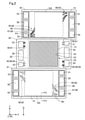
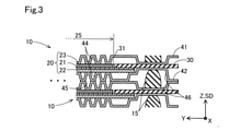
図2および図3を参照し、燃料電池セル10の構成を説明する。図2は、燃料電池セル10を分解して示す概略図である。図2には、カソード23側から積層方向SDに見たときの膜電極接合体20と、樹脂フレーム30と、一対のセパレータ41,42と、が図示されている。図3は、図2に示すF3-F3切断に相当する位置における燃料電池セル10の概略断面図である。図3では、燃料電池スタック100を構成したときの任意の隣り合う2つの燃料電池セル10を例示してある。
The configuration of the
図2および図3には、互いに直交する三方向を示すX,Y,Z軸が図示されている。ここで、第1実施形態では、図2に示すように、樹脂フレーム30および一対のセパレータ41,42は、積層方向SDに見たときに略四角状の外周形状を有している。X軸およびY軸はそれぞれ、樹脂フレーム30およびセパレータ41,42の外周の一辺に沿った方向を示している。以下では、X軸に沿った方向であるX軸方向のうち、+の方向を+X方向とも呼び、-の方向を-X方向とも呼ぶ。また、Y軸に沿った方向であるY軸方向のうち、+の方向を+Y方向とも呼び、-の方向を-Y方向とも呼ぶ。Z軸に沿った方向であるZ軸方向は、樹脂フレーム30およびセパレータ41,42の厚み方向と、燃料電池スタック100の積層方向SDと、に平行である。X,Y,Z軸は、後に参照する他の参照図においても、図2および図3と対応するように、適宜、図示してある。
2 and 3 show X, Y, and Z axes indicating three directions orthogonal to each other. Here, in the first embodiment, as shown in FIG. 2, the
図2を参照する。燃料電池セル10では、膜電極接合体20は、その周囲に枠状の樹脂フレーム30が配置された状態で一対のセパレータ41,42に挟まれる。第1実施形態では、膜電極接合体20は、積層方向SDに見たときに、その外周端部が樹脂フレーム30の内周端部と重なるように配置される。
See FIG. In the
図3を参照する。膜電極接合体20は、電解質膜21と、電解質膜21の両面に配置された電極層であるアノード22およびカソード23と、を備える。電解質膜21は湿潤状態において良好なプロトン伝導性を示す電解質樹脂の薄膜である。電解質膜21は、例えば、フッ素系のイオン交換膜によって構成される。
See FIG. The
アノード22およびカソード23は、燃料ガスと酸化剤ガスの電気化学反応を促進する触媒粒子が担持されている導電性材料によって構成される。アノード22およびカソード23は、内部においてX軸およびY軸によって規定される面に沿った方向にガスが拡散するガス拡散性を有する。膜電極接合体20においてアノード22およびカソード23が配置されている領域が、供給された反応ガスの電気化学反応によって発電がおこなわれる発電部25である。
The
第1実施形態では、カソード23のX軸方向における長さおよびY軸方向における長さは電解質膜21およびアノード22より小さい。カソード23は、その外周端部が、電解質膜21の外周端部およびアノード22の外周端部より内側に位置するように、電解質膜21の面上に配置されている。カソード23の外周端部の外側に延び出ている電解質膜21の外周端部は、樹脂フレーム30の開口部31の内側周縁部に接合される。これによって、膜電極接合体20は、図2に示すように、樹脂フレーム30の中央の開口部31内に、膜電極接合体20の発電部25が配置された状態で、樹脂フレーム30に支持される。樹脂フレーム30は、例えば、ポリエチレンテレフタレート(PET)によって構成される。樹脂部材としては、ポリプロピレン、ポリエチレン等の他の種々の熱可塑性樹脂部材を採用することができる。
In the first embodiment, the length of the
図2に示すように、一対のセパレータ41,42は、膜電極接合体20およびそれを支持する樹脂フレーム30をほぼ覆うことができる程度のサイズを有している。図2では、各セパレータ41,42において膜電極接合体20の発電部25とZ軸方向に重なる領域GAが一点鎖線で図示されている。第1セパレータ41は、カソード23に面するカソードセパレータであり、第2セパレータ42は、アノード22に面するアノードセパレータである。
As shown in FIG. 2, the pair of
セパレータ41,42は導電性およびガス不透過性を有する板状部材によって構成される。第1実施形態では、各セパレータ41,42は、メタルセパレータであり、ステンレス鋼やチタンなどの金属部材をプレス成形したプレス成形板によって構成されている。他の実施形態では、セパレータ41,42はメタルセパレータによって構成されていなくてもよい。セパレータ41,42は、例えば、カーボンを板状に成形した部材によって構成されてもよい。
The
図2を参照する。燃料電池セル10は、発電部25の周囲に設けられたマニホールド部51~56を有する。マニホールド部51~56は、樹脂フレーム30およびセパレータ41,42を貫通する貫通孔によって構成される。上述したように、燃料電池スタック100において、各燃料電池セル10のマニホールド部51~56は積層方向SDに連結され、図1で説明したマニホールドM1~M6を構成する。マニホールド部51~56はそれぞれ、符号の末尾の数字が同じである対応するマニホールドM1~M6を構成する。
See FIG. The
反応ガスの供給用のマニホールド部51,53は、各燃料電池セル10の一対のセパレータ41,42の間に反応ガスを流入させる。反応ガスの排出用のマニホールド部52,54は、各燃料電池セル10の一対のセパレータ41,42の間から排ガスを流出させる。冷媒供給用のマニホールド部55は、燃料電池スタック100において互いに隣り合って積層された燃料電池セル10同士の間に冷媒を流入させる。冷媒排出用のマニホールド部56は、当該互いに隣り合って積層された燃料電池セル10同士の間を通過した冷媒を流出させる。
燃料ガス供給用の第1マニホールド部51は、発電部25の+Y方向側の端部の+X方向側に設けられている。アノード22側の排ガス用の第2マニホールド部52は、発電部25の-Y方向側の端部の-X方向側に設けられている。第1マニホールド部51と第2マニホールド部52とは、発電部25を挟んで対角の位置に設けられている。
The
酸化剤ガス供給用の第3マニホールド部53は、発電部25の+Y方向側の端部の-X方向側に設けられている。カソード23側の排ガス用の第4マニホールド部54は、発電部25の-Y方向側の端部の+X方向側に設けられている。第3マニホールド部53と第4マニホールド部54とは、発電部25を挟んで対角の位置に設けられている。
The
冷媒供給用の第5マニホールド部55は、発電部25の+X方向側に設けられ、Y軸方向において第1マニホールド部51と第4マニホールド部54とに挟まれている。冷媒排出用の第6マニホールド部56は、発電部25の-X方向側に設けられ、Y軸方向において第2マニホールド部52と第3マニホールド部53とに挟まれている。
The
マニホールド部51~56が形成される位置は上記の位置に限定されることはない。マニホールド部51~56は、発電部25の周囲に形成されていればよい。なお、第1実施形態では、燃料ガス用のマニホールド部51,52の開口面積は、酸化剤ガス用のマニホールド部53,54の開口面積より小さい。そして、燃料ガス用のマニホールド部51,52のY軸方向における開口幅は、酸化剤ガス用のマニホールド部53,54のY軸方向における開口幅より小さい。
The position where the
燃料電池セル10には、一対のセパレータ41,42の間に、反応ガス供給用のマニホールド部51,53と発電部25とを接続し、マニホールド部51,53の反応ガスを発電部25に導く供給ガス流路60が設けられている。供給ガス流路60は、第1マニホールド部51と発電部25との間、および、第3マニホールド部53と発電部25との間、にそれぞれ設けられている。
In the
反応ガス供給用のマニホールド部51,53に連結されている上流側供給流路61と、発電部25に連結されている下流側供給流路62と、を含む。上流側供給流路61は、樹脂フレーム30に設けられた溝状、あるいは、スリット状の凹部と、当該凹部を覆うセパレータ41,42の表面との間の空間によって構成されている。図2では、樹脂フレーム30の右上の部位に図示されている燃料ガス用の上流側供給流路61は、樹脂フレーム30の裏側に設けられているため、破線で図示してある。
It includes an upstream side supply flow path 61 connected to the
下流側供給流路62は、セパレータ41,42の樹脂フレーム30側の面に設けられた溝状の凹部と、当該凹部を覆う樹脂フレーム30の表面との間の空間によって構成されている。図2では、第1セパレータ41の左上の部位に図示されている酸化剤ガス用のカソード側の下流側供給流路62は、第1セパレータ41の裏側に設けられているため、破線で図示してある。下流側供給流路62を構成するセパレータ41,42の凹部は、プレス加工によってセパレータ41,42の基材を厚み方向に凹凸するように折り曲げることによって形成されてもよい。セパレータ41,42の当該凹部は、エッチング処理など、セパレータ41,42の基材表面に対する溝掘り加工によって形成されてもよい。このように、供給ガス流路60は、一対のセパレータ41,42の少なくとも一方と樹脂フレーム30とによって構成されている。
The downstream supply flow path 62 is composed of a space between a groove-shaped recess provided on the surface of the
燃料電池セル10には、発電部25と排ガス用のマニホールド部52,54とを接続し、排ガスをマニホールド部52,54に導く排ガス流路65が設けられている。排ガス流路65は、一対のセパレータ41,42に設けられている。排ガスには、発電部25において発電に用いられなかった反応ガスと、発電部25において生成された水分と、が含まれる。
The
複数の排ガス流路65は、発電部25と第2マニホールド部52との間と、発電部25と第4マニホールド部54との間と、にそれぞれ設けられている。排ガス流路65は、供給ガス流路60と同様に、一対のセパレータ41,42のうちの少なくとも一方と樹脂フレーム30とで構成される。排ガス流路65は、セパレータ41,42側に設けられたセパレータ側流路部68として構成された部位と、樹脂フレーム30側に設けられた樹脂フレーム側流路部69として構成された部位と、を含む。
A plurality of exhaust gas flow paths 65 are provided between the
セパレータ側流路部68は、セパレータ41,42の樹脂フレーム30側の面に設けられた溝状の凹部と、当該凹部に面する樹脂フレーム30の表面との間の空間によって構成されている。図2では、第1セパレータ41の右下の部位に図示されているカソード23側の排ガス用のセパレータ側流路部68は、第1セパレータ41の裏側に設けられているため、破線で図示してある。
The separator-side
以下では、セパレータ側流路部68を構成するためのセパレータ41,42の凹部を「セパレータ側凹部」とも呼ぶ。第1実施形態では、セパレータ側凹部は、セパレータ41,42の基材をプレス加工によって厚み方向に凹凸するように折り曲げることによって形成される。ただし、他の実施形態では、セパレータ側凹部は、プレス加工の代わりに、エッチング処理など、セパレータ41,42の基材表面に対する溝掘り加工によって形成されてもよい。
Hereinafter, the recesses of the
樹脂フレーム側流路部69は、樹脂フレーム30に設けられる溝状の凹部と、当該凹部に面するセパレータ41,42の表面との間の空間によって構成されている。図2では、樹脂フレーム30の左下の部位に図示されているアノード22側の排ガス用の樹脂フレーム側流路部69は、樹脂フレーム30の裏側に設けられているため、破線で図示してある。
The resin frame side
以下では、樹脂フレーム側流路部69を構成するための樹脂フレーム30の凹部を「フレーム側凹部」とも呼ぶ。第1実施形態では、フレーム側凹部は、樹脂フレーム30の表面を局所的に窪ませた有底の凹部によって構成される。他の実施形態では、フレーム側凹部としては、例えば、スリットや貫通孔など、樹脂フレーム30を貫通する構成が採用されてもよい。
Hereinafter, the recess of the
排ガス流路65は、発電部25からマニホールド部52,54へと並列に延びている複数の並列流路66と、並列流路66に交差する方向に延びている連結流路67と、を有する。並列流路66の上流端は、発電部25に接続されており、並列流路66の上流側は、セパレータ側流路部68によって構成されている。並列流路66の下流端は、マニホールド部52,54に接続されており、並列流路66の下流側は、樹脂フレーム側流路部69によって構成されている。並列流路66では、並列流路66を構成しているセパレータ側流路部68の下流端部と樹脂フレーム側流路部69の上流端部とがZ軸方向に重なり合うことによって、並列流路66の上流側と下流側とが連結されている。
The exhaust gas flow path 65 has a plurality of
複数の並列流路66は、発電部25側の上流端同士の間隔が、マニホールド部52,54側の下流端同士の間隔より広く、発電部25からマニホールド部52,54に向かって集まるように延びている。これによって、発電部25におけるより広い範囲から排ガスを効率良くマニホールド部52,54へと集めることができる。なお、上述したように、第1実施形態の燃料電池セル10では、燃料ガス用のマニホールドM1,M2のY軸方向における開口幅は、酸化剤ガス用のマニホールドM3,M4のY軸方向における開口幅よりも小さい。そのため、第1実施形態では、アノード側の並列流路66の本数は、カソード側の並列流路66の本数よりも少ない。
In the plurality of
連結流路67は、並列流路66のうちの少なくとも一部を連結する連結部として機能する。第1実施形態では、連結流路67は、セパレータ側流路部68として構成されている。第1実施形態では、連結流路67は、Y軸方向に沿って延びており、並列流路66のうち、+Y方向側に配列されている流路に連結され、-Y方向側に配列されている流路には連結されていない。なお、他の実施形態では、連結流路67は、全ての並列流路66に連結されていてもよい。また、-Y方向側に配列されている流路にのみ連結されていてもよいし、並列流路66のY軸方向における中央の領域に配列されている流路にのみ連結されていてもよい。並列流路66および連結流路67は、排ガスに含まれる液体成分が毛管力によって保持されて滞留してしまわない程度の流路断面積を有することが望ましい。
The connecting
排ガス流路65では、並列流路66と連結流路67とは、連結流路67に連結されている並列流路66の一部に、流入する排ガス中の液体成分の量が他よりも低減される流路が形成されるように接続されている。その詳細については後述する。
In the exhaust gas flow path 65, the
図3を参照する。セパレータ41,42の膜電極接合体20側の面である内側面には、発電部25と面する領域GAの全体にわたって、反応ガスの流路を構成するガス流路溝44が形成されている。また、セパレータ41,42のその反対側の外側面には、冷媒の流路を構成する冷媒流路溝45が形成されている。なお、図2では、便宜上、ガス流路溝44および冷媒流路溝45の平面視の図示は省略されている。また、本明細書では、冷媒流路溝45と冷媒用のマニホールド部55,56とを接続する流路の構成についての説明は省略する。
See FIG. On the inner surface of the
図3に示すように、セパレータ41,42の樹脂フレーム30とは反対側の外側面には、図1で説明したシール部材15を収容するための空間を形成する溝状のシール収納凹部46が設けられている。シール部材15は、積層方向SDに見たときに、図2に示すように、発電部25と各マニホールド部51~56をそれぞれ囲むように配置されている。図2では、便宜上、シール収納凹部46の図示は省略されている。
As shown in FIG. 3, on the outer surface of the
図2を参照する。図2には、重力方向を示す矢印Gを図示してある。なお、重力方向を示す矢印Gは、後に参照する他の図においても図2に対応するように図示してある。第1実施形態の燃料電池スタック100は、発電の際には、-Y方向側が重力方向下側となるように配置される。つまり、燃料電池スタック100は、発電の際に、反応ガス供給用のマニホールド部51,53が重力方向上側となり、排ガス用のマニホールド部52,54が重力方向下側となるように配置される。そのため、発電中の発電部25では、アノード22側においてもカソード23側においても、反応ガスが重力方向上側から下側へと流れる。これによって、発電部25で生成された水分が重力に従って発電部25の下方へと移動するため、当該水分が発電部25から排出されやすくなっている。
See FIG. FIG. 2 shows an arrow G indicating the direction of gravity. The arrow G indicating the direction of gravity is shown so as to correspond to FIG. 2 in other figures referred to later. The
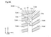
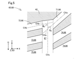
図4A、図4B、図5を順に参照して、第1実施形態の排ガス流路65の流路構成を説明する。図4Aは、図2に示す領域F4に含まれる排ガス流路65の一部を、一対のセパレータ41,42が樹脂フレーム30を挟んで対向する方向である積層方向SDに見たときの概略平面図である。図4Aでは、便宜上、排ガス流路65の内部空間を白抜きで示し、排ガス流路65の壁部を構成するセパレータ42の部分を、斜線ハッチングを付して示してある。
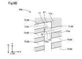
The flow path configuration of the exhaust gas flow path 65 of the first embodiment will be described with reference to FIGS. 4A, 4B, and 5 in order. FIG. 4A shows a schematic plane when a part of the exhaust gas flow path 65 included in the region F4 shown in FIG. 2 is viewed in the stacking direction SD in which the pair of
以下における排ガス流路65の構成の説明は、特に断らない限り、一対のセパレータ41,42が樹脂フレーム30を挟んで対向する方向に見たときのものである。以下では、アノード側の排ガス流路65の構成について説明する。第1実施形態の燃料電池セル10では、カソード側の排ガス流路65も、アノード側の排ガス流路65と同様な構成を有している。以下のアノード側の排ガス流路65についての説明を、カソード側の排ガス流路65に適用する場合には、第2マニホールド部52が第4マニホールド部54に置き換えられ、+X方向および-X方向の正負が入れ替えられる。
Unless otherwise specified, the description of the configuration of the exhaust gas flow path 65 below is when the pair of
排ガス流路65の並列流路66は、連結流路67よりも上流側の第1流路部71と、連結流路67よりも下流側の第2流路部72および第3流路部73を有する。第1流路部71は、発電部25から第2マニホールド部52に向かう方向に延びており、その下流端が連結流路67に接続されている。第1実施形態では、第1流路部71は、その下流側部位71dが、発電部25から-X方向側および-Y方向側に向かって斜めに延びて、連結流路67に接続されている。
The
第2流路部72および第3流路部73は、連結流路67から互いに並列に延びており、それぞれの上流端が連結流路67に接続されている。本明細書において、「並列に延びている」構成は、平行に延びている構成に限定されず、互いに交差する方向に延びている構成も含む。第2流路部72と第3流路部73とは、並列流路66の配列方向において互いに隣り合っている。第2流路部72は+Y方向側に位置し、第3流路部73は-Y方向側に位置する。
The second flow path portion 72 and the third flow path portion 73 extend in parallel with each other from the
第2流路部72および第3流路部73のそれぞれの下流端は、図2において図示されているように、別個に第2マニホールド部52に接続されている。なお、第1実施形態では、第2流路部72と第3流路部73の上流側部位は、第1流路部71および連結流路67と同様に、セパレータ側流路部68として構成されている。第2流路部72と第3流路部73の下流側部位は、樹脂フレーム側流路部69として構成されている。
The downstream ends of the second flow path portion 72 and the third flow path portion 73 are separately connected to the
第1実施形態では、並列流路66は、連結流路67の上流側に、第1流路部71の他に、上流側流路部74を有している。上流側流路部74は、第1流路部71の-Y方向側において、発電部25から第2マニホールド部52に向かって延び、下流端が連結流路67に接続されている。第1実施形態では、連結流路67よりも上流側の流路である第1流路部71および上流側流路部74は、連結流路67から発電部25に向かって放射状に延びている。他の実施形態では、上流側流路部74は省略されてもよいし、連結流路67から発電部25に向かって放射状に延びていなくてもよい。
In the first embodiment, the
第1実施形態では、並列流路66は、連結流路67の下流側に、第2流路部72および第3流路部73の他に、下流側流路部75を有している。下流側流路部75は、第3流路部73よりも-Y方向側に位置し、上流端が連結流路67に接続され、それぞれの下流端が第2マニホールド部52に接続されている。なお、下流側流路部75では、第2流路部72および第3流路部73と同様に、上流側がセパレータ側流路部68として構成され、下流側が樹脂フレーム側流路部69として構成されている。他の実施形態では、下流側流路部75は省略されてもよい。
In the first embodiment, the
第1流路部71の下流端は、連結流路67において最も上流に位置する。連結流路67において、第1流路部71の下流端に対して、第2流路部72と第3流路部73の配列方向のうちの第3流路部73から第2流路部72に向かう方向側の領域には、発電部25から延びている流路は接続されていない。つまり、連結流路67において、第1流路部71の下流端よりも+Y方向側の領域には発電部25から延びている流路は接続されていない。第1流路部71は、下流端が連結流路67に連結されている流路のうち、並列流路66の配列方向において最も外側に位置する。
The downstream end of the first flow path portion 71 is located most upstream in the connecting
第1流路部71の下流側部位71dは、連結流路67に対して、第2流路部72から第3流路部73に向かう方向である-Y方向側に向かって傾斜して接続されている。第1流路部71の下流端の中心軸CXaに平行な中心軸方向に見たときに、第1流路部71の下流端は、第2流路部72の上流端に対して、第2流路部72から第3流路部73に向かう方向側、つまり、+Y方向側に位置する。
The
なお、本明細書において、流路の中心軸とは、当該流路に直交する流路断面における中心を結ぶ仮想軸を意味する。また、流路の下流端や上流端における中心軸は、流路の上流端や下流端を構成する開口における中心位置での中心軸を意味する。 In the present specification, the central axis of the flow path means a virtual axis connecting the centers in the cross section of the flow path orthogonal to the flow path. Further, the central axis at the downstream end and the upstream end of the flow path means the central axis at the central position in the openings constituting the upstream end and the downstream end of the flow path.
図4Aでは、第1流路部71の下流端を連結流路67内に延長した延長領域77に、網点のハッチングが付されている。第1流路部71の下流端の延長領域77は、第1流路部71の下流端を構成する+Y方向側の壁面の接線C1と-Y方向側の壁面の接線C2とに挟まれている領域である。
In FIG. 4A, halftone dots are hatched in the
延長領域77は、第1流路部71の下流端における中心軸CXaを連結流路67内に延長した延長軸EXaに沿った方向に延びている。延長軸EXaは、第2流路部72の上流端よりも第3流路部73の上流端側の領域に向かって、第2流路部72の上流端の中心軸CXbに対して斜めに交差する方向に延びている。
The
延長領域77の延長方向における端部77eは、連結流路67において、第2流路部72の上流端よりも第3流路部73の上流端側、つまり、-Y方向側に位置する。第2流路部72の上流端は、延長領域77の端部77eと重なる部位を有していない。第1実施形態では、延長領域77の端部77eは、第3流路部73の上流端と重なる部位を有している。なお、他の実施形態では、第3流路部73の上流端は、延長領域77の端部77eと重なる部位を有しないように、延長領域77の端部77eよりも-Y方向側に位置していてもよい。
The
延長領域77は、第2流路部72の上流端がない領域であって、第2流路部72の上流端から見て第3流路部73がある方側の領域に向かって延びている。つまり、第1流路部71は、その下流端を連結流路67内に延長した延長領域77が、第2流路部72の上流端側ではなく、第3流路部73の上流端側に向かって延びるように、連結流路67に接続している。
The
ここで、排ガス流路65は、第2流路部72の上流端から、第2流路部72の上流端の中心軸CXbに対して交差する方向に延びている交差壁面部79を有している。交差壁面部79は、第2流路部72の上流端に対して、第2流路部72と第3流路部73の配列方向のうちの第2流路部72から第3流路部73に向かう方向側に位置する。第1実施形態では、交差壁面部79は、連結流路67の壁面の一部を構成しており、第2流路部72の上流端と第3流路部73の上流端との間に位置している。
Here, the exhaust gas flow path 65 has an intersecting
交差壁面部79は、第2流路部72の上流端から、第1流路部71の下流端の中心軸CXaに直交する方向に交差する方向であって、第1流路部71の下流端から離れる方向に延びている。交差壁面部79は、第1流路部71の下流端の中心軸CXaに対して、第2流路部72から第3流路部73に向かう方向に傾斜して交差している。交差壁面部79は、第1流路部71の下流端の中心軸CXaに対して、交差壁面部79と第1流路部71の下流端の中心軸CXaとの間の角度のうち、第3流路部73側の角度が第2流路部72側の角度より大きくなるように傾斜して交差している。第1実施形態では、第1流路部71の下流端は、その中心軸CXaに平行な中心軸方向において、交差壁面部79と、第3流路部73の上流端と、に対向している。
The intersecting
燃料電池セル10では、第1流路部71と第2流路部72と第3流路部73とが、連結流路67に対して、上記のように接続されていることによって、以下に説明するように、排ガスの液体成分が第2流路部72へと進入することが抑制されている。
In the
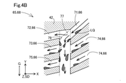
図4Bを参照して、排ガス流路65での排ガスの流れを説明する。図4Bでは、図4Aで図示した排ガス流路65に、排ガスの気体成分の流れを示す矢印と、排ガスに含まれる液体成分LQと、が模式的に図示されている。 The flow of exhaust gas in the exhaust gas flow path 65 will be described with reference to FIG. 4B. In FIG. 4B, an arrow indicating the flow of the gas component of the exhaust gas and the liquid component LQ contained in the exhaust gas are schematically illustrated in the exhaust gas flow path 65 shown in FIG. 4A.
連結流路67には、発電部25から並列流路66のそれぞれに、排ガスの気体成分とともに、排ガスの液体成分LQが流入する。排ガスの気体成分は、液体成分LQに比較して、運動量が小さく、移動方向が変化しやすい。第1流路部71から連結流路67に流出した排ガスの気体成分は、連結流路67において拡散し、連結流路67を通じて、第2流路部72や、第3流路部73、下流側流路部75に分岐流入する。第1流路部71以外の他の上流側流路部74から連結流路67に流出した排ガスの気体成分についても同様である。
The liquid component LQ of the exhaust gas flows into the connected
一方、第1流路部71から連結流路67に流出した排ガスの液体成分LQは、気体成分よりも運動量が大きいため、その多くが、慣性力に従って、第1流路部71の下流端の延長領域77に沿って、交差壁面部79に向かって移動する。そして、液体成分LQは、前述の慣性力のY軸方向に沿った成分によって、連結流路67内を-Y方向に移動し、連結流路67よりも下流側の第3流路部73や他の下流側流路部75に流入する。第1実施形態では、上述したように、交差壁面部79が、第1流路部71の下流端の中心軸CXaに対して第2流路部72から第3流路部に向かう方向に傾斜している。そのため、排ガスの液体成分LQは交差壁面部79によって第2流路部72の上流端側から第3流路部73の上流端側へと誘導される。第1流路部71以外の他の上流側流路部74から連結流路67に流出した排ガスの液体成分LQも、連結流路67に沿って-Y方向に移動し、第3流路部73や他の下流側流路部75に流入する。
On the other hand, since the liquid component LQ of the exhaust gas flowing out from the first flow path portion 71 to the connecting
このように、排ガス流路65の流路構成によれば、第1流路部71の排ガスのうち、運動量が大きい液体成分LQが、第2流路部72ではなく、第3流路部73の方へと誘導される。そして、運動量が小さく、液体成分LQから分離された気体成分の一部が第2流路部72へと流入する。上述したように、第1流路部71の下流端は、連結流路67において最も上流に位置し、第1流路部71の延長領域77よりも+Y方向側の領域には発電部25から延びて連結流路67に接続する流路がない。そのため、第1流路部71以外から第2流路部72へと排ガスの液体成分LQが進入する可能性は低い。
As described above, according to the flow path configuration of the exhaust gas flow path 65, among the exhaust gas of the first flow path portion 71, the liquid component LQ having a large momentum is not the second flow path portion 72 but the third flow path portion 73. You will be guided towards. Then, the momentum is small, and a part of the gas component separated from the liquid component LQ flows into the second flow path portion 72. As described above, the downstream end of the first flow path portion 71 is located most upstream in the connecting
よって、燃料電池スタック100の発電中に、第2流路部72に排ガスの液体成分LQが流入することが抑制され、第2流路部72に流入する水分量が、第3流路部73や他の下流側流路部75より低減される。また、仮に、第2流路部72に液体成分LQが入り込んでしまったとしても、第2流路部72へ流入する気体成分の圧力によって、第2流路部72の下流へと液体成分LQが排出される。そのため、第2流路部72が液体成分LQによって閉塞されてしまうことが抑制され、燃料電池スタック100の発電停止後に、第2流路部72に多量の水分が残留してしまうことが抑制される。よって、外気温が氷点下になるような低温環境下において、排ガス流路65の全てが残留水分の凍結によって閉塞されて、燃料電池スタック100の発電再開が困難になってしまうことが抑制される。
Therefore, during the power generation of the
ここで、第1実施形態の燃料電池セル10は、その発電の際には、第2流路部72が重力方向上側となり、第3流路部73が重力方向下側となるように配置される。そのため、排ガスの液体成分LQは、重力の作用によっても、連結流路67において、第2流路部72よりも下方の流路部73,75へと誘導される。よって、排ガスの液体成分LQの第2流路部72への流入がより一層、抑制される。
Here, the
また、第1実施形態の燃料電池セル10では、上述したように、アノード側の並列流路66の本数は、カソード側の並列流路66の本数よりも少ない。第1実施形態では、そうした並列流路66の本数の少ないアノード側の排ガス流路65に第2流路部72を有する構成が適用されている。そのため、排水量に対して並列流路66の数が少ないアノード側の排ガス流路65が、排水によって閉塞しやすくなってしまうことが抑制されている。また、第1実施形態の燃料電池セル10では、カソード側の排ガス流路65においても、液体成分LQの流入が抑制される第2流路部72を有する構成が適用されているため、残留水分による排ガス流路65の閉塞が、さらに抑制されている。
Further, in the
図5を参照して、第1流路部71と第2流路部72と連結流路67とが交差する角度について説明する。連結流路67の中心軸CXcと、第1流路部71の下流端の中心軸CXaを連結流路67内に延長した延長軸EXaとの間の角度のうち、+Y方向側の角度、つまり、第2流路部72側の角度をθaとする。また、連結流路67の中心軸CXcと、第2流路部72の下流端の中心軸CXbを連結流路67内に延長した延長軸EXbと、の間の角度のうち、-Y方向側の角度、つまり、第3流路部73側の角度をθbとする。このとき、θbはθaよりも大きいことが望ましい。また、θbとθaとの差が大きいほど望ましい。これによって、第1流路部71から連結流路67に流入した排ガスの液体成分LQが、第2流路部72側ではなく、第3流路部73側へと、より一層、誘導されるようになる。そのため、排ガスの液体成分LQの第2流路部72への進入を、さらに効果的に抑制することができる。
With reference to FIG. 5, the angle at which the first flow path portion 71, the second flow path portion 72, and the connecting
以上のように、第1実施形態の燃料電池セル10および燃料電池スタック100によれば、排ガス流路65において、排ガスの液体成分LQが第2流路部72に流入することが抑制される。よって、燃料電池スタック100の発電停止後に、第2流路部72に水分が残留することが抑制され、低温環境下において、全ての排ガス流路65が残留水分の凍結によって閉塞されて、発電の再開が困難になってしまうことが抑制される。その他に、第1実施形態の燃料電池セル10および燃料電池スタック100によれば、第1実施形態中で説明した種々の作用効果を奏することができる。
As described above, according to the
2.第2実施形態:
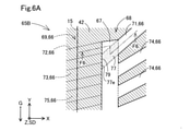
図6Aおよび図6Bを参照して、第2実施形態の燃料電池セルが有する排ガス流路65Bの構成を説明する。図6Aは、第2実施形態の排ガス流路65Bの一部を積層方向SDに沿って見たときの概略平面図である。図6Aでは、図4Aと同様に、アノード側の排ガス流路65Bについて、排ガス流路65Bの内部空間を白抜きで示し、排ガス流路65Bの壁部を構成するセパレータ42の部分を、斜線ハッチングを付して示してある。図6Bは、図6Aに示すF6-F6切断における第2実施形態の燃料電池セルの概略断面図である。
2. 2. Second embodiment:
The configuration of the exhaust
第2実施形態の燃料電池セルおよび燃料電池スタックの構成は、第2実施形態の排ガス流路65Bを有している点以外は、第1実施形態の燃料電池セル10および燃料電池スタック100の構成とほぼ同じである。第2実施形態の排ガス流路65Bの構成は、以下で特に説明しない点については、第1実施形態の排ガス流路65の構成とほぼ同じである。なお、第2実施形態の燃料電池セルおよび燃料電池スタックでは、第1実施形態と同様に、排ガス流路65Bの構成は、アノード側とカソード側とで共通である。
The configuration of the fuel cell and the fuel cell stack of the second embodiment is the configuration of the
排ガス流路65Bでは、第1流路部71は、第1実施形態で説明したのと同様に、セパレータ側流路部68として形成されている。つまり、第1流路部71は、セパレータ41,42の樹脂フレーム30側の面に設けられたセパレータ側凹部47と樹脂フレーム30との間の空間によって構成されている。第1流路部71以外の他の上流側流路部74についても同様に、セパレータ側流路部68として形成されている。
In the exhaust
排ガス流路65Bでは、第1実施形態とは異なり、第2流路部72および第3流路部73の上流側部位は、樹脂フレーム側流路部69として形成されている。つまり、第2流路部72および第3流路部73は、上流端から下流端にわたって、樹脂フレーム30のフレーム側凹部37と、当該フレーム側凹部37に面するセパレータ41,42の表面との間の空間によって構成されている。他の下流側流路部75についても同様に、上流端から下流端にわたって、樹脂フレーム側流路部69として形成されている。なお、図6Aでは、樹脂フレーム側流路部69はセパレータ41,42に覆われて見えないため、その位置を破線で図示してある。
In the exhaust
図6Bを参照する。排ガス流路65Bでは、連結流路67は、セパレータ側凹部47とフレーム側凹部37とが対向して形成される空間によって構成されている。つまり、連結流路67は、セパレータ側流路部68として形成されている部位と、樹脂フレーム側流路部69として形成されている部位と、が積層方向SDに重ねられて構成されている。そのため、排ガス流路65Bでは、交差壁面部79は、セパレータ41,42の一部と樹脂フレーム30の一部とで構成されている。なお、交差壁面部79は、図6Bには表れていない。
See FIG. 6B. In the exhaust
第2実施形態の排ガス流路65Bによれば、図6Bに示すように、第1流路部71の下流端と、第2流路部72の上流端とが、連結流路67内において、Z軸方向において離間した位置で開口している。そのため、第1流路部71の下流端から流出した排ガスの液体成分が、第2流路部72に流入することが、さらに抑制される。
According to the exhaust
図6Aには、第1実施形態において図2および図3を参照して説明したシール部材15が配置される位置を一点鎖線で図示してある。連結流路67よりも下流側の樹脂フレーム側流路部69である第2流路部72と第3流路部73と他の下流側流路部75は、燃料電池セル10を積層方向SDに見たときに、シール部材15の下方において、シール部材15と交差するように延びている。
In FIG. 6A, the position where the
ここで、樹脂フレーム側流路部69は、樹脂フレーム30がセパレータ41,42を介してシール部材15から押圧力を受けて厚み方向に圧縮されることによって、その流路径が小さくなってしまう場合がある。排ガス流路65Bによれば、第2流路部72への排ガスの液体成分の進入が抑制されるため、シール部材15によって樹脂フレーム側流路部69の流路径が小さくなっていても、少なくとも、第2流路部72が液体成分によって閉塞されることが抑制される。また、シール部材15を支持するための反力を得るために、シール部材15と交差する樹脂フレーム側流路部69の流路径を、より小さく設計することも可能になる。
Here, the resin frame side
以上のように、第2実施形態の排ガス流路65Bを備える燃料電池セルおよび燃料電池スタックによれば、第2流路部72への排ガスの液体成分の進入をより効果的に抑制できる。また、第2実施形態中で説明した種々の作用効果に加えて、第1実施形態中で説明したのと同様な種々の作用効果を奏することができる。
As described above, according to the fuel cell and the fuel cell stack provided with the exhaust
3.第3実施形態:
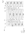
図7は、第3実施形態の排ガス流路65Cの一部を積層方向SDに沿って見たときの概略平面図である。図7では、図4Aと同様に、アノード側の排ガス流路65Cについて、排ガス流路65Cの内部空間を白抜きで示し、排ガス流路65Cの壁部を構成するセパレータ42の部分を、斜線ハッチングを付して示してある。
3. 3. Third embodiment:
FIG. 7 is a schematic plan view when a part of the exhaust
第3実施形態の燃料電池セルおよび燃料電池スタックの構成は、第3実施形態の排ガス流路65Cを有している点以外は、第1実施形態の燃料電池セル10および燃料電池スタック100の構成とほぼ同じである。第3実施形態の排ガス流路65Cの構成は、以下で特に説明しない点については、第1実施形態の排ガス流路65の構成とほぼ同じである。なお、第3実施形態の燃料電池セルおよび燃料電池スタックでは、第1実施形態と同様に、排ガス流路65Cの構成は、アノード側とカソード側とで共通である。以下における排ガス流路65Cの構成の説明は、特に断らない限り、一対のセパレータ41,42が樹脂フレーム30を挟んで対向する方向に見たときのものである。
The configuration of the fuel cell and the fuel cell stack of the third embodiment is the configuration of the
第3実施形態の排ガス流路65Cは、連結流路67の上流側、つまり、連結流路67と発電部25との間にも、並列流路66に交差するように延びている連結流路82を有している。以下では、区別のために、下流側の連結流路67を「第1連結流路67」とも呼び、その上流側の連結流路82を「第2連結流路82」とも呼ぶ。
The exhaust
第2連結流路82には、第1流路部71の上流端と、第1流路部71と並列に延びている他の上流側流路部74の上流端と、が接続されている。以下では、上流側流路部74のうち、第1流路部71の-Y方向側に位置し、第1流路部71と隣り合う並列な流路を、特に、「第4流路部84」と呼ぶ。第4流路部84の下流端は、第1流路部71の下流端と同様に、第1連結流路67に接続されている。第4流路部84の上流端は、第1流路部71の上流端よりも第2連結流路82の下流側において、第2連結流路82に接続されている。
The upstream end of the first flow path portion 71 and the upstream end of another upstream side flow path portion 74 extending in parallel with the first flow path portion 71 are connected to the second connecting
排ガス流路65Cは、さらに、第2連結流路82よりも上流側に位置する第5流路部85を有している。第5流路部85の下流端は第2連結流路82に接続されている。また、排ガス流路65Cは、第5流路部85の-Y方向側に、並列な複数の流路部86を有している。各流路部86の下流端は、第2連結流路82に接続され、上流端は発電部25に接続されている。以下では、第1連結流路67に接続されている上流側流路部74を「第1上流側流路部74」と呼び、第2連結流路82に接続されている複数の並列な流路部86を「第2上流側流路部86」とも呼ぶ。
The exhaust
第5流路部85の下流端は、第2連結流路82において最も上流に位置している。第2連結流路82における第5流路部85の下流端よりも、第1流路部71と第4流路部84の配列方向のうちの第4流路部84から第1流路部71に向かう方向側の領域には、上流側が発電部25に接続されている流路は接続されていない。つまり、第2連結流路82における第5流路部85の下流端よりも+Y方向側の領域には、上流側が発電部25に接続されている流路は接続されていない。第5流路部85は、発電部25と第2連結流路82とを接続する並列流路66の配列方向において最も外側に位置する。第5流路部85の下流端の中心軸CXeに平行な中心軸方向に見たときに、第5流路部85の下流端は、第1流路部71の上流端に対して、第1流路部71と第4流路部84の配列方向のうちの第1流路部71から第4流路部84に向かう方向側に位置する。
The downstream end of the fifth flow path portion 85 is located most upstream in the second connecting
第5流路部85の下流端を第2連結流路82内に延長した延長領域87は、第2連結流路82において、第1流路部71の上流端側ではなく、第4流路部84の上流端側に向かって延びている。延長領域87は、第1流路部71の上流端がない領域であって、第1流路部71の上流端から見て、第4流路部84がある方の領域に向かって延びている。以下、第1実施形態で説明した第1連結流路67内における第1流路部71の下流端の延長領域77を「第1延長領域77」と呼び、第2連結流路82内における第5流路部85の下流端の延長領域87を「第2延長領域87」と呼ぶ。第2延長領域87は、第5流路部85の下流端を構成する+Y方向側の壁面の接線C3と-Y方向側の壁面の接線C4とに挟まれている領域である。
The
第2延長領域87は、第5流路部85の下流端における中心軸CXeを第2連結流路82内に延長した延長軸EXeに沿った方向に延びている。延長軸EXeは、第1流路部71の上流端よりも第4流路部84の上流端側の領域に向かって、第1流路部71の上流端の中心軸CXfに対して斜めに交差する方向に延びている。第2連結流路82の第2延長領域87よりも+Y方向側、つまり、第4流路部84から第1流路部71に向かう方向側の領域には、上流側が発電部25に接続されている流路は接続されていない。
The
第2延長領域87の延長方向における端部87eは、第2連結流路82において、第1流路部71の上流端よりも第4流路部84の上流端側、つまり、-Y方向側に位置する。第1流路部71の上流端は、第2延長領域87の端部87eと重なる部位を有していない。第3実施形態では、第4流路部84の上流端は、第2延長領域87の端部87eと重なる部位を有している。他の実施形態では、第4流路部84の上流端は、第2延長領域87の端部87eと重なる部位を有しないように、第2延長領域87の端部87eよりも-Y方向側に位置していてもよい。
The
ここで、排ガス流路65Cは、第1流路部71の上流端から、第1流路部71の上流端の中心軸CXfに対して交差する方向に延びている交差壁面部89を有している。交差壁面部89は、第1流路部71の上流端に対して、第1流路部71と第4流路部84の配列方向のうちの第1流路部71から第4流路部84に向かう方向側に位置する。交差壁面部89は、第2連結流路82の壁面の一部を構成しており、第1流路部71の上流端と第4流路部84の上流端との間に位置している。以下、第1実施形態で説明した第1連結流路67内の交差壁面部79を「第1交差壁面部79」と呼び、第2連結流路82内の交差壁面部89を「第2交差壁面部89」と呼ぶ。
Here, the exhaust
第2交差壁面部89は、第1流路部71の上流端から、第5流路部85の下流端の中心軸CXeに直交する方向に交差する方向であって、第5流路部85の下流端から離れる方向に延びている。第2交差壁面部89は、第5流路部85の下流端の中心軸CXeに対して、第1流路部71から第4流路部84に向かう方向に傾斜して交差している。第2交差壁面部89は、第5流路部85の下流端の中心軸CXeに対して、第2交差壁面部89と第5流路部85の下流端の中心軸CXeとの間の角度のうち、第4流路部84側の角度が第1流路部71側の角度より大きくなるように傾斜して交差している。第5流路部85の下流端は、その中心軸CXeに平行な中心軸方向において、第2交差壁面部89と、第4流路部84の上流端と、に対向している。
The second crossing
排ガス流路65Cでは、第5流路部85から第2連結流路82へと流入した排ガスの液体成分の移動経路は、図4Bで説明した第1流路部71から第1連結流路67へと流入した排ガスの液体成分LQと同様になる。排ガス流路65Cでは、第5流路部85から第2連結流路82に流入した排ガスの液体成分は、第2延長領域87に沿って移動した後、第2交差壁面部89に沿って-Y方向側へと誘導されるため、第1流路部71に流入することが抑制される。また、排ガス流路65Cでは、仮に、第1流路部71に排ガスの液体成分が流入したとしても、当該液体成分は、第1連結流路67を介して第2流路部72へと流入することが抑制される。このように、排ガス流路65Cでは、第2連結流路82と第1連結流路67の二段階で、第2流路部72へと到達して流入する水分量が低減されている。よって、残留水分による排ガス流路65Cの閉塞が、より一層、効果的に抑制される。
In the exhaust
排ガス流路65Cでは、第1流路部71の下流側部位71dは、第2流路部72から第3流路部73に向かう-Y方向側に湾曲して第1連結流路67に接続している。また、同様に、第5流路部85の下流側部位85dは、第1流路部71から第4流路部84に向かう-Y方向側に湾曲して第2連結流路82に接続している。
In the exhaust
第1流路部71の下流側部位71dが上記のように湾曲していることによって、下流側部位71dが湾曲していない構成よりも、第1流路部71の上流側部位を-Y方向側に位置させることができる。第5流路部85の下流側部位85dについても同様である。よって、排ガス流路65Cが形成される範囲のY軸方向における幅が大きくなることを抑制できる。
Since the
第3実施形態では、第1流路部71に隣り合う第4流路部84の下流側部位は、第1流路部71の下流側部位71dと干渉しないように、第1流路部71の下流側部位71dと同様に湾曲している。また、第5流路部85に隣り合う第2上流側流路部86の下流側部位も、第5流路部85の下流側部位85dと干渉しないように、第5流路部85の下流側部位85dと同様に湾曲している。これによって、第1流路部71と第4流路部84との間隔および第5流路部85とその隣の第2上流側流路部86との間隔を狭くすることができ、排ガス流路65Cが形成される範囲のY軸方向における幅をより小さくすることができる。
In the third embodiment, the downstream portion of the fourth flow path portion 84 adjacent to the first flow path portion 71 does not interfere with the
以上、第3実施形態の排ガス流路65Cを備える燃料電池セルおよび燃料電池スタックによれば、第2流路部72への排ガスの液体成分の進入が、さらに抑制される。また、第1流路部71の下流側部位71dおよび第5流路部85の下流側部位85dに湾曲部を設けることによって、排ガス流路65Cの形成領域が広がってしまうことが抑制されている。その他に、第3実施形態の燃料電池セルおよび燃料電池スタックによれば、第3実施形態中で説明した種々の作用効果に加えて、第1実施形態中や第2実施形態中で説明したのと同様な種々の作用効果を奏することができる。
As described above, according to the fuel cell and the fuel cell stack provided with the exhaust
4.第4実施形態:
図8は、第4実施形態の排ガス流路65Dを積層方向SDに沿って見たときの概略平面図である。図8では、図4Aと同様に、アノード側の排ガス流路65Dについて、排ガス流路65Dの内部空間を白抜きで示し、排ガス流路65Dの壁部を構成するセパレータ42の部分を、斜線ハッチングを付して示してある。第4実施形態の燃料電池セルおよび燃料電池スタックの構成は、第4実施形態の排ガス流路65Dを有している点以外は、第1実施形態の燃料電池セル10および燃料電池スタック100の構成とほぼ同じである。なお、第4実施形態の燃料電池セルおよび燃料電池スタックでは、第1実施形態と同様に、排ガス流路65Dの構成は、アノード側とカソード側とで共通である。以下における排ガス流路65Dの構成の説明は、特に断らない限り、一対のセパレータ41,42が樹脂フレーム30を挟んで対向する方向に見たときのものである。
4. Fourth Embodiment:
FIG. 8 is a schematic plan view of the exhaust
排ガス流路65Dは、発電部25からマニホールド部52,54に向かって並列に延びる複数の並列流路90を有する。各並列流路90の上流端は発電部25に接続され、下流端はマニホールド部52,54に接続されている。複数の並列流路90は、分岐流路94を含んでいる。分岐流路94は、上流側の第1流路部91と、第1流路部91から分岐している下流側の第2流路部92と第3流路部93とを有する。分岐流路94では、第1流路部91と第3流路部93とは直線状に並んでおり、第2流路部92は、第1流路部91と第3流路部93とに対して斜めに交差するように接続している。
The exhaust
第1流路部91は発電部25からマニホールド部52,54に向かって延び、その下流端が連結部95に接続されている。第2流路部92と第3流路部93の上流端は連結部95に接続されている。第2流路部92と第3流路部93とは、連結部95から互いに並列に延びてそれぞれの下流端が別個にマニホールド部52,54に接続されている。なお、図示はされていないが、第2流路部92と第3流路部93の下流側部位は、第1実施形態で説明した樹脂フレーム側流路部69として構成されている。
The first
ここで、分岐流路94において、連結部95は、第2流路部92の上流端に面している領域である。第1流路部91は、第2流路部92の上流端よりも上流側の流路であり、第3流路部93は第2流路部の上流端よりも下流側の流路である。第1流路部91の下流端は、連結部95において最も上流に位置している。また、第2流路部92の上流端は、第3流路部93の上流端よりも連結部95の上流端側において、連結部95に接続されている。
Here, in the branch flow path 94, the connecting
第2流路部92の上流端は、連結部95に接続されている第1流路部91の下流端を連結部95内に延長した延長領域97の+Y方向側に位置している。第1流路部91の延長領域97は、第2流路部92の上流端側ではなく、第3流路部93の上流端側に向かって延びている。延長領域97は、第2流路部92の上流端がない領域であって、第2流路部92の上流端から見たときに、第3流路部93の上流端がある方の領域に向かって延びている。連結部95における延長領域97よりも+Y方向側の領域、つまり、第3流路部93から第2流路部92に向かう方向側の領域には、発電部25から延びている流路は接続されていない。
The upstream end of the second
積層方向SDに見たときに、第1流路部91の下流端は、連結部95を挟んで、第1流路部91の下流端の中心軸CXgに平行な中心軸方向において、第3流路部93の上流端と対向している。分岐流路94は、第2流路部92の上流端から、第2流路部92の上流端の中心軸CXhに対して交差する方向に延びている交差壁面部99を有している。交差壁面部99は、第2流路部92の上流端に対して第2流路部92から第3流路部93に向かう方向側に位置する。
When viewed in the stacking direction SD, the downstream end of the first
積層方向SDに見たときに、交差壁面部99は、第1流路部91の下流端の中心軸CXgに直交する方向に交差する方向であって、第2流路部92の上流端から第1流路部91の下流端から離れる方向に延びている。交差壁面部99は、第3流路部93の壁面の一部を構成しており、第3流路部93の中心軸に沿って延びている。交差壁面部99は、第1流路部91の下流端とは、その中心軸CXgに平行な中心軸方向において対向していない。
When viewed in the stacking direction SD, the intersecting
排ガス流路65Dの分岐流路94では、第1流路部91を流れる排ガスのうち、運動量が小さい気体成分は、第2流路部92と第3流路部93とに分岐して流れる。一方、運動量が大きい液体成分のほとんどは、連結部95内の延長領域97に沿ってそのまま第3流路部93へと流入し、交差壁面部99によって第3流路部93の下流側へと誘導される。このように、排ガス流路65Dの分岐流路94では、第2流路部92への排ガスの液体成分の進入が抑制される。そのため、少なくとも、第2流路部92では、燃料電池セルおよび燃料電池スタックの発電停止後に水分が残留することが抑制される。よって、残留水分によって排ガス流路65Dの全てが閉塞されてしまうことが抑制される。その他に、第4実施形態の燃料電池セルおよび燃料電池スタックによれば、第4実施形態中で説明した種々の作用効果に加えて、他の各実施形態中で説明したのと同様な種々の作用効果を奏することができる。
In the branch flow path 94 of the exhaust
5.他の実施形態:
上記の各実施形態で説明した種々の構成は、例えば、以下のように改変することが可能である。以下に説明する他の実施形態はいずれも、上記の各実施形態と同様に、発明を実施するための形態の一例として位置づけられる。
5. Other embodiments:
The various configurations described in each of the above embodiments can be modified, for example, as follows. Each of the other embodiments described below is positioned as an example of an embodiment for carrying out the invention, similarly to each of the above embodiments.
(1)他の実施形態1:
図9A~図9Cを参照して、第1実施形態における排ガス流路65の他の構成例を説明する。図9Aに示す排ガス流路65aのように、第1流路部71の下流端は、第3流路部73の上流端と対向せず、交差壁面部79のみと対向していてもよい。図9Bに示す排ガス流路65bのように、第1流路部71は、第2流路部72および第3流路部73とほぼ平行な角度で延びていてもよい。第1流路部71の下流端の延長領域77が延びる方向に平行なベクトルが、第2流路部72の上流端側から第3流路部73の上流端側に向かう方向の成分を有し、延長領域77が第2流路部72の上流端よりも第3流路部73の上流端側に位置していればよい。図9Cに示す排ガス流路65cのように、第2流路部72と第3流路部73とは互いに交差する方向に延びていてもよい。
(1) Other Embodiment 1:
Other configuration examples of the exhaust gas flow path 65 in the first embodiment will be described with reference to FIGS. 9A to 9C. As in the exhaust
(2)他の実施形態2:
上記の各実施形態の排ガス流路65,65B~65C,65a~65cにおいて、連結流路67に接続されている第1流路部71、第2流路部72、および、第3流路部73以外の流路部74,75は省略されてもよい。上記の各実施形態の排ガス流路65,65B~65Cにおいて、連結流路67の+Y方向側に、連結流路67に接続されず、発電部25とマニホールド部52,54とを接続する流路が設けられていてもよい。第4実施形態の排ガス流路65Dにおいて、分岐流路94以外の並列流路90が省略されていてもよい。分岐流路94の+Y方向側に他の並列流路90が設けられていてもよい。
(2) Other Embodiment 2:
In the exhaust
(3)他の実施形態3:
他の実施形態を含む上記の各実施形態の構成において、第1流路部71,91、第2流路部72,92、第3流路部73,93、連結流路67、および、連結部95は、樹脂フレーム側流路部69として構成されていてもよい。第3実施形態の排ガス流路65Cにおいて、第2連結流路82および第2連結流路82よりも下流側の流路が樹脂フレーム側流路部69として構成されていてもよい。第3実施形態の排ガス流路65Cにおいて、第1流路部71、第2流路部72、第3流路部73、第1連結流路67、第4流路部84、第5流路部85、第2連結流路82が樹脂フレーム側流路部69として構成されていてもよい。第4実施形態の排ガス流路65Dにおいて、第1流路部71がセパレータ側流路部68によって構成され、第2流路部92および第3流路部93が樹脂フレーム側流路部69によって構成されてもよい。また、連結部95が、セパレータ側凹部47とフレーム側凹部37とが対向して形成される空間によって構成されていてもよい。
(3) Other Embodiment 3:
In the configuration of each of the above embodiments including other embodiments, the first
(4)他の実施形態4:
燃料電池セル10の発電中の配置姿勢は、上記の各実施形態で説明した第2流路部72,92が重力方向上側となり、第3流路部73,93が重力方向下側となる姿勢には限定されない。燃料電池セル10は、発電中に、例えば、積層方向SDが重力方向に沿った方向となるように配置されてもよい。
(4) Other Embodiment 4:
The arrangement posture of the
(5)他の実施形態5:
上記の各実施形態における排ガス流路65,65B~65Dの流路構成は、アノード側とカソード側の両方に適用されていなくてもよく、アノード側とカソード側のいずれか一方にのみ適用されていてもよい。なお、上実施形態における排ガス流路65,65B~65Dの流路構成は、少なくとも、アノード側に適用されることが望ましい。
(5) Other Embodiment 5:
The flow path configurations of the exhaust
本発明は、上述の実施形態や実施例、変形例に限られるものではなく、その趣旨を逸脱しない範囲において種々の構成で実現することができる。例えば、発明の概要の欄に記載した各形態中の技術的特徴に対応する実施形態、実施例、変形例中の技術的特徴は、上述の課題の一部又は全部を解決するために、あるいは、上述の効果の一部又は全部を達成するために、適宜、差し替えや、組み合わせを行うことが可能である。また、その技術的特徴が本明細書中に必須ではないと説明されているものに限らず、その技術的特徴が本明細書中に必須であると説明されていなければ、適宜、削除することが可能である。 The present invention is not limited to the above-described embodiments, examples, and modifications, and can be realized with various configurations within a range not deviating from the gist thereof. For example, the technical features in the embodiments, examples, and modifications corresponding to the technical features in each of the embodiments described in the column of the outline of the invention may be used to solve some or all of the above-mentioned problems. , Can be replaced or combined as appropriate to achieve some or all of the above effects. In addition, the technical features are not limited to those described in the present specification as not essential, and if the technical features are not described as essential in the present specification, they may be appropriately deleted. Is possible.
10…燃料電池セル、11…積層体、12a…第1エンドプレート、12b…第2エンドプレート、13…集電板、14…絶縁板、15…シール部材、20…膜電極接合体、21…電解質膜、22…アノード、23…カソード、25…発電部、30…樹脂フレーム、31…開口部、37…フレーム側凹部、41…第1セパレータ、42…第2セパレータ、44…ガス流路溝、45…冷媒流路溝、46…シール収納凹部、47…セパレータ側凹部、51~56…マニホールド部、60…供給ガス流路、61…上流側供給流路、62…下流側供給流路、65,65B~65D,65a~65c…排ガス流路、66…並列流路、67…連結流路/第1連結流路、68…セパレータ側流路部、69…樹脂フレーム側流路部、71…第1流路部、71d…下流側部位、72…第2流路部、73…第3流路部、74…上流側流路部/第1上流側流路部、75…下流側流路部、77…延長領域/第1延長領域、77e…端部、79…交差壁面部/第1交差壁面部、82…第2連結流路、84…第4流路部、85…第5流路部、85d…下流側部位、86…第2上流側流路部、87…第2延長領域、87e…端部、89…第2交差壁面部、90…並列流路、91…第1流路部、92…第2流路部、93…第3流路部、94…分岐流路、95…連結部、97…延長領域、99…交差壁面部、100…燃料電池スタック、C1~C4…接線、CXa~CXc,CXe~CXh…中心軸、EXa,EXb,EXe…延長軸、LQ…液体成分、M1~M6…マニホールド 10 ... fuel cell, 11 ... laminated body, 12a ... first end plate, 12b ... second end plate, 13 ... current collector plate, 14 ... insulating plate, 15 ... sealing member, 20 ... membrane electrode assembly, 21 ... Electrolyte membrane, 22 ... anode, 23 ... cathode, 25 ... power generation unit, 30 ... resin frame, 31 ... opening, 37 ... frame side recess, 41 ... first separator, 42 ... second separator, 44 ... gas flow path groove , 45 ... Fuel flow path groove, 46 ... Seal storage recess, 47 ... Separator side recess, 51-56 ... Manifold portion, 60 ... Supply gas flow path, 61 ... Upstream side supply flow path, 62 ... Downstream side supply flow path, 65, 65B to 65D, 65a to 65c ... Exhaust gas flow path, 66 ... Parallel flow path, 67 ... Connection flow path / first connection flow path, 68 ... Separator side flow path portion, 69 ... Resin frame side flow path portion, 71 ... 1st flow path portion, 71d ... downstream side portion, 72 ... 2nd flow path portion, 73 ... 3rd flow path portion, 74 ... upstream side flow path portion / first upstream side flow path portion, 75 ... downstream side flow Road portion, 77 ... extension region / first extension region, 77e ... end portion, 79 ... intersection wall surface portion / first intersection wall surface portion, 82 ... second connecting flow path, 84 ... fourth flow path portion, 85 ... fifth. Flow path portion, 85d ... downstream side portion, 86 ... second upstream side flow path portion, 87 ... second extension region, 87e ... end portion, 89 ... second crossing wall surface portion, 90 ... parallel flow path, 91 ... first Channel part, 92 ... 2nd flow path part, 93 ... 3rd flow path part, 94 ... branch flow path, 95 ... connection part, 97 ... extension area, 99 ... cross wall surface part, 100 ... fuel cell stack, C1 ~ C4 ... tangent line, CXa to CXc, CXe to CXh ... central axis, EXa, EXb, EXe ... extension shaft, LQ ... liquid component, M1 to M6 ... manifold
Claims (11)
膜電極接合体と、
前記膜電極接合体の発電部の周囲に配置される樹脂フレームと、
前記膜電極接合体と前記樹脂フレームとを挟む一対のセパレータと、
前記発電部の周囲に設けられ、前記発電部から排出される排ガスを前記燃料電池セルから流出させるマニホールド部と、
前記一対のセパレータのうちの少なくとも一方と前記樹脂フレームとによって構成され、前記排ガスを前記発電部から前記マニホールド部に導く排ガス流路と、
を備え、
前記排ガス流路は、
前記発電部から前記マニホールド部に向かう方向に延びている第1流路部と、
前記第1流路部より下流側において互いに並列に延びてそれぞれの下流端が前記マニホールド部に接続されている第2流路部および第3流路部と、
前記第1流路部の下流端と、前記第2流路部の上流端と、前記第3流路部の上流端と、に接続されている連結部と、
を含み、
前記一対のセパレータが前記樹脂フレームを挟んで互いに対向する方向に見たときに、
前記第1流路部は、前記第1流路部の下流端を前記連結部内に延長した延長領域が、前記連結部において、前記第2流路部の上流端側ではなく、前記第3流路部の上流端側に向かって延びるように、前記連結部に接続しており、
前記連結部において、前記延長領域に対して、前記第2流路部と前記第3流路部の配列方向のうち、前記第2流路部から前記第3流路部に向かう方向側の領域には、前記発電部から延びている流路は接続されていない、燃料電池セル。 It ’s a fuel cell,
Membrane electrode assembly and
A resin frame arranged around the power generation unit of the membrane electrode assembly and
A pair of separators sandwiching the membrane electrode assembly and the resin frame,
A manifold portion provided around the power generation unit and allowing exhaust gas discharged from the power generation unit to flow out from the fuel cell.
An exhaust gas flow path formed by at least one of the pair of separators and the resin frame and guiding the exhaust gas from the power generation unit to the manifold unit.
Equipped with
The exhaust gas flow path is
A first flow path portion extending in a direction from the power generation portion toward the manifold portion, and a first flow path portion.
A second flow path portion and a third flow path portion extending in parallel with each other on the downstream side of the first flow path portion and having their respective downstream ends connected to the manifold portion.
A connecting portion connected to a downstream end of the first flow path portion, an upstream end of the second flow path portion, and an upstream end of the third flow path portion.
Including
When the pair of separators are viewed in the directions facing each other across the resin frame,
In the first flow path portion, the extension region in which the downstream end of the first flow path portion is extended into the connection portion is not the upstream end side of the second flow path portion in the connection portion, but the third flow. It is connected to the connecting portion so as to extend toward the upstream end side of the road portion.
In the connecting portion, a region of the arrangement direction of the second flow path portion and the third flow path portion on the direction side from the second flow path portion toward the third flow path portion with respect to the extension region. The fuel cell is not connected to the flow path extending from the power generation unit.
前記連結部は、前記第2流路部と前記第3流路部とに交差するように延びる連結流路であり、
前記一対のセパレータが前記樹脂フレームを挟んで対向する方向に沿って見たときに、
前記第1流路部の下流側部位は、前記第2流路部から前記第3流路部に向かう方向に傾斜して前記連結流路に接続しており、
前記延長領域の延長方向における端部は、前記第2流路部の上流端に対して、前記第2流路部から前記第3流路部に向かう方向側に位置する、燃料電池セル。 The fuel cell according to claim 1.
The connecting portion is a connecting flow path extending so as to intersect the second flow path portion and the third flow path portion.
When the pair of separators are viewed along the opposite directions across the resin frame,
The downstream portion of the first flow path portion is inclined in the direction from the second flow path portion toward the third flow path portion and is connected to the connecting flow path.
The end portion in the extension direction of the extension region is a fuel cell located on the side in the direction from the second flow path portion toward the third flow path portion with respect to the upstream end of the second flow path portion.
膜電極接合体と、
前記膜電極接合体の発電部の周囲に配置される樹脂フレームと、
前記膜電極接合体と前記樹脂フレームとを挟む一対のセパレータと、
前記発電部の周囲に設けられ、前記発電部から排出される排ガスを前記燃料電池セルから流出させるマニホールド部と、
前記一対のセパレータのうちの少なくとも一方と前記樹脂フレームとによって構成され、前記排ガスを前記発電部から前記マニホールド部に導く排ガス流路と、
を備え、
前記排ガス流路は、
前記発電部から前記マニホールド部に向かう方向に延びている第1流路部と、
前記第1流路部より下流側において互いに並列に延びてそれぞれの下流端が前記マニホールド部に接続されている第2流路部および第3流路部と、
前記第1流路部の下流端と、前記第2流路部の上流端と、前記第3流路部の上流端と、に接続されている連結部と、
前記第2流路部の上流端に対して、前記第2流路部から前記第3流路部に向かう方向側に位置し、前記第2流路部の上流端から、前記第2流路部の上流端の中心軸に対して交差する方向に延びている交差壁面部と、
を含み、
前記第1流路部の下流端は、前記連結部において最も上流に位置し、
前記第1流路部の下流端の中心軸方向に見たときに、前記第1流路部の下流端は、前記第2流路部の上流端に対して、前記第2流路部から前記第3流路部に向かう方向側に位置し、
前記一対のセパレータが前記樹脂フレームを挟んで互いに対向する方向に見たときに、
前記第1流路部の下流端は、前記交差壁面部と、前記第3流路部の上流端と、のうちの少なくとも一方と、前記第1流路部の下流端の中心軸方向において対向し、
前記交差壁面部は、前記第2流路部の上流端から、前記第1流路部の下流端の中心軸に直交する方向に交差する方向であって、前記第1流路部の下流端から離れる方向に延びている、燃料電池セル。 It ’s a fuel cell,
Membrane electrode assembly and
A resin frame arranged around the power generation unit of the membrane electrode assembly and
A pair of separators sandwiching the membrane electrode assembly and the resin frame,
A manifold portion provided around the power generation unit and allowing exhaust gas discharged from the power generation unit to flow out from the fuel cell.
An exhaust gas flow path formed by at least one of the pair of separators and the resin frame and guiding the exhaust gas from the power generation unit to the manifold unit.
Equipped with
The exhaust gas flow path is
A first flow path portion extending in a direction from the power generation portion toward the manifold portion, and a first flow path portion.
A second flow path portion and a third flow path portion extending in parallel with each other on the downstream side of the first flow path portion and having their respective downstream ends connected to the manifold portion.
A connecting portion connected to a downstream end of the first flow path portion, an upstream end of the second flow path portion, and an upstream end of the third flow path portion.
It is located on the upstream end of the second flow path portion in the direction from the second flow path portion toward the third flow path portion, and from the upstream end of the second flow path portion, the second flow path portion. The crossing wall surface extending in the direction intersecting the central axis of the upstream end of the section,
Including
The downstream end of the first flow path portion is located most upstream in the connecting portion.
When viewed in the direction of the central axis of the downstream end of the first flow path portion, the downstream end of the first flow path portion is from the second flow path portion with respect to the upstream end of the second flow path portion. Located on the direction side toward the third flow path portion,
When the pair of separators are viewed in the directions facing each other across the resin frame,
The downstream end of the first flow path portion faces at least one of the intersecting wall surface portion and the upstream end of the third flow path portion in the central axis direction of the downstream end of the first flow path portion. death,
The intersecting wall surface portion is in a direction intersecting from the upstream end of the second flow path portion in a direction orthogonal to the central axis of the downstream end of the first flow path portion, and is the downstream end of the first flow path portion. A fuel cell that extends away from.
前記連結部は、前記第2流路部と前記第3流路部とに交差する方向に延びる連結流路であり、
前記交差壁面部は、前記連結流路の壁面の一部を構成しており、
前記一対のセパレータが前記樹脂フレームを挟んで対向する方向に見たときに、前記第1流路部の下流側部位は、前記交差壁面部に対して、前記第2流路部から前記第3流路部に向かう方向に傾斜して前記連結流路に接続している、燃料電池セル。 The fuel cell according to claim 3, wherein the fuel cell is
The connecting portion is a connecting flow path extending in a direction intersecting the second flow path portion and the third flow path portion.
The intersecting wall surface portion constitutes a part of the wall surface of the connecting flow path.
When the pair of separators are viewed in a direction facing each other with the resin frame interposed therebetween, the downstream portion of the first flow path portion is from the second flow path portion to the third with respect to the intersecting wall surface portion. A fuel cell that is inclined in a direction toward a flow path portion and is connected to the connecting flow path.
前記連結流路は、第1連結流路であり、
前記延長領域は、第1延長領域であり、
前記排ガス流路は、さらに、
前記第1流路部と並列に延び、下流端が前記第1連結流路に接続されている第4流路部と、
前記第1流路部の上流端と前記第4流路部の上流端とが接続されている第2連結流路と、
前記第2連結流路より上流側に位置し、下流端が前記第2連結流路に接続されている第5流路部と、
を含み、
前記一対のセパレータが前記樹脂フレームを挟んで互いに対向する方向に見たときに、
前記第5流路部は、下流端を前記第2連結流路内に延長した第2延長領域が、前記第2連結流路において、前記第1流路部の上流端側ではなく、前記第4流路部の上流端側に向かって延びるように、前記第2連結流路に接続しており、
前記第2延長領域に対して、前記第1流路部と前記第4流路部の配列方向のうち、前記第4流路部から前記第1流路部に向かう方向側における前記第2連結流路の領域には、上流側が前記発電部に接続されている流路は接続されていない、燃料電池セル。 The fuel cell according to claim 2, wherein the fuel cell is
The connecting flow path is a first connecting flow path, and is
The extension region is a first extension region.
The exhaust gas flow path further
A fourth flow path portion extending in parallel with the first flow path portion and having a downstream end connected to the first connecting flow path.
A second connecting flow path in which the upstream end of the first flow path portion and the upstream end of the fourth flow path portion are connected,
A fifth flow path portion located on the upstream side of the second connecting flow path and having a downstream end connected to the second connecting flow path.
Including
When the pair of separators are viewed in the directions facing each other across the resin frame,
In the fifth flow path portion, the second extension region in which the downstream end is extended into the second connecting flow path is not the upstream end side of the first flow path portion in the second connecting flow path, but the first. 4 It is connected to the second connecting flow path so as to extend toward the upstream end side of the flow path portion.
The second connection with respect to the second extension region on the side of the arrangement direction of the first flow path portion and the fourth flow path portion in the direction from the fourth flow path portion to the first flow path portion. A fuel cell in which a flow path whose upstream side is connected to the power generation unit is not connected to the flow path region.
前記連結流路は第1連結流路であり、
前記交差壁面部は第1交差壁面部であり、
前記排ガス流路は、さらに、
前記第1流路部と並列に延び、下流端が前記第1連結流路に接続されている第4流路部と、
前記第1流路部の上流端と前記第4流路部の上流端とが接続されている第2連結流路と、
前記第2連結流路より上流側に位置し、下流端が前記第2連結流路に接続されている第5流路部と、
前記第1流路部の上流端に対して、前記第1流路部から前記第4流路部に向かう方向側に位置し、前記第1流路部の上流端から、前記第1流路部の上流端の中心軸に対して交差する方向に延びている第2交差壁面部と、
を含み、
前記第5流路部の下流端は、前記第2連結流路において最も上流に位置し、
前記第5流路部の下流端の中心軸方向に見たときに、前記第5流路部の下流端は、前記第1流路部の上流端に対して、前記第1流路部から前記第4流路部に向かう方向側に位置し、
前記一対のセパレータが前記樹脂フレームを挟んで互いに対向する方向に見たときに、
前記第5流路部の下流端は、前記第2交差壁面部と、前記第4流路部の上流端と、のうちの少なくとも一方と、前記第5流路部の下流端の中心軸方向において対向し、
前記第2交差壁面部は、前記第1流路部の上流端から、前記第5流路部の下流端の中心軸に直交する方向に交差する方向であって、前記第5流路部の下流端から離れる方向に延びている、燃料電池セル。 The fuel cell according to claim 4, wherein the fuel cell is
The connecting flow path is the first connecting flow path.
The crossing wall surface portion is a first crossing wall surface portion, and is
The exhaust gas flow path further
A fourth flow path portion extending in parallel with the first flow path portion and having a downstream end connected to the first connecting flow path.
A second connecting flow path in which the upstream end of the first flow path portion and the upstream end of the fourth flow path portion are connected,
A fifth flow path portion located on the upstream side of the second connecting flow path and having a downstream end connected to the second connecting flow path.
It is located on the upstream end of the first flow path portion in the direction from the first flow path portion toward the fourth flow path portion, and from the upstream end of the first flow path portion, the first flow path. The second crossing wall surface extending in the direction intersecting the central axis of the upstream end of the section,
Including
The downstream end of the fifth flow path portion is located most upstream in the second connection flow path.
When viewed in the direction of the central axis of the downstream end of the fifth flow path portion, the downstream end of the fifth flow path portion is from the first flow path portion with respect to the upstream end of the first flow path portion. Located on the side toward the fourth flow path portion,
When the pair of separators are viewed in the directions facing each other across the resin frame,
The downstream end of the fifth flow path portion is at least one of the second crossing wall surface portion and the upstream end of the fourth flow path portion, and the direction of the central axis of the downstream end of the fifth flow path portion. Facing at
The second crossing wall surface portion is a direction that intersects from the upstream end of the first flow path portion in a direction orthogonal to the central axis of the downstream end of the fifth flow path portion, and is a direction of the fifth flow path portion. A fuel cell that extends away from the downstream end.
前記第1流路部は、前記第2流路部から前記第3流路部に向かう方向に湾曲して前記第1連結流路に接続し、
前記第5流路部は、前記第1流路部から前記第4流路部に向かう方向に湾曲して前記第2連結流路に接続している、燃料電池セル。 The fuel cell according to claim 5 or 6.
The first flow path portion is curved in a direction from the second flow path portion toward the third flow path portion to connect to the first connecting flow path portion.
The fifth flow path portion is a fuel cell that is curved in a direction from the first flow path portion toward the fourth flow path portion and is connected to the second connecting flow path.
前記一対のセパレータが前記樹脂フレームを挟んで互いに対向する方向に見たときに、
前記連結流路の中心軸と前記第2流路部の上流端の中心軸との間の前記第3流路部側の角度θbは、前記連結流路の中心軸と前記第1流路部の下流端の中心軸との間の前記第2流路部側の角度θaよりも大きい、燃料電池セル。 The fuel cell according to any one of claims 2 and 4 to 7.
When the pair of separators are viewed in the directions facing each other across the resin frame,
The angle θb on the third flow path side between the central axis of the connecting flow path and the central axis of the upstream end of the second flow path portion is the central axis of the connecting flow path and the first flow path portion. A fuel cell whose angle is greater than the angle θa on the side of the second flow path with respect to the central axis at the downstream end of the fuel cell.
前記第1流路部は、前記一対のセパレータのうちの一方のセパレータにおける前記樹脂フレーム側の面に設けられたセパレータ側凹部と、前記樹脂フレームと、の間の空間によって構成され、
前記第2流路部および前記第3流路部は、前記樹脂フレームの前記一方のセパレータ側の面に設けられたフレーム側凹部と、前記一方のセパレータと、の間の空間によって構成され、
前記連結部は、前記セパレータ側凹部と前記フレーム側凹部とが対向して形成される空間によって構成されている、燃料電池セル。 The fuel cell according to any one of claims 1 to 8.
The first flow path portion is composed of a space between the separator-side recess provided on the resin frame-side surface of one of the pair of separators and the resin frame.
The second flow path portion and the third flow path portion are composed of a space between a frame-side recess provided on the surface of the resin frame on the separator side and the one separator.
The connecting portion is a fuel cell cell formed by a space formed by facing the separator-side recess and the frame-side recess.
前記第2流路部が重力方向上側となり、前記第3流路部が重力方向下側となるように配置される、燃料電池セル。 The fuel cell according to any one of claims 1 to 9.
A fuel cell in which the second flow path portion is on the upper side in the gravity direction and the third flow path portion is on the lower side in the gravity direction.
前記燃料電池セル同士の間において、前記マニホールド部を囲み、互いに対向する前記セパレータに挟まれて、前記燃料電池セル同士の間からの流体の漏洩を防止するシール部材が配置され、
前記第2流路部および前記第3流路部は、前記樹脂フレーム内に設けられ、前記燃料電池セルの積層方向に沿って見たときに、前記シール部材と交差するように延びている、燃料電池スタック。 The fuel cell according to any one of claims 1 to 10 is a fuel cell stack in which a plurality of fuel cells are stacked.
Between the fuel cell cells, a seal member that surrounds the manifold portion and is sandwiched between the separators facing each other to prevent fluid leakage from between the fuel cell cells is arranged.
The second flow path portion and the third flow path portion are provided in the resin frame and extend so as to intersect the seal member when viewed along the stacking direction of the fuel cell. Fuel cell stack.
Priority Applications (3)
| Application Number | Priority Date | Filing Date | Title |
|---|---|---|---|
| JP2018111845A JP6996430B2 (en) | 2018-06-12 | 2018-06-12 | Fuel cell and fuel cell stack |
| US16/430,796 US10873093B2 (en) | 2018-06-12 | 2019-06-04 | Fuel cell and fuel cell stack |
| CN201910497552.0A CN110600760B (en) | 2018-06-12 | 2019-06-10 | Fuel cell unit and fuel cell stack |
Applications Claiming Priority (1)
| Application Number | Priority Date | Filing Date | Title |
|---|---|---|---|
| JP2018111845A JP6996430B2 (en) | 2018-06-12 | 2018-06-12 | Fuel cell and fuel cell stack |
Publications (2)
| Publication Number | Publication Date |
|---|---|
| JP2019216002A JP2019216002A (en) | 2019-12-19 |
| JP6996430B2 true JP6996430B2 (en) | 2022-02-04 |
Family
ID=68764535
Family Applications (1)
| Application Number | Title | Priority Date | Filing Date |
|---|---|---|---|
| JP2018111845A Active JP6996430B2 (en) | 2018-06-12 | 2018-06-12 | Fuel cell and fuel cell stack |
Country Status (3)
| Country | Link |
|---|---|
| US (1) | US10873093B2 (en) |
| JP (1) | JP6996430B2 (en) |
| CN (1) | CN110600760B (en) |
Families Citing this family (2)
| Publication number | Priority date | Publication date | Assignee | Title |
|---|---|---|---|---|
| SE1930019A1 (en) * | 2019-01-23 | 2020-07-21 | Powercell Sweden Ab | Unit fuel cell, fuel cell stack and bipolar plate assembly |
| JP7226392B2 (en) * | 2020-05-15 | 2023-02-21 | トヨタ自動車株式会社 | fuel cell stack |
Citations (6)
| Publication number | Priority date | Publication date | Assignee | Title |
|---|---|---|---|---|
| US20020064702A1 (en) | 1998-12-30 | 2002-05-30 | Gibb Peter R. | Fuel cell fluid flow field plate and methods of making fuel cell flow field plates |
| JP2006012466A (en) | 2004-06-22 | 2006-01-12 | Nissan Motor Co Ltd | Fuel cell |
| JP2010182515A (en) | 2009-02-05 | 2010-08-19 | Honda Motor Co Ltd | Fuel cell |
| JP2014175237A (en) | 2013-03-12 | 2014-09-22 | Nippon Soken Inc | Fuel cell |
| JP2015225709A (en) | 2014-05-26 | 2015-12-14 | トヨタ自動車株式会社 | Separator for fuel cell and fuel cell |
| JP2016119177A (en) | 2014-12-19 | 2016-06-30 | 三菱重工業株式会社 | Solid polymer fuel battery |
Family Cites Families (11)
| Publication number | Priority date | Publication date | Assignee | Title |
|---|---|---|---|---|
| JP2000012048A (en) * | 1998-06-18 | 2000-01-14 | Toyota Motor Corp | Fuel cell gas separator, fuel cell using the fuel cell separator, and method of manufacturing fuel cell gas separator |
| US7261966B2 (en) * | 2003-06-30 | 2007-08-28 | Zongshen Pem Power Systems Inc. | Apparatus and method for conducting fluid in a fuel cell and fuel cell employing same |
| JP2009206076A (en) * | 2008-01-28 | 2009-09-10 | Canon Inc | Fuel battery cell, and fuel cell stack |
| JP5423892B2 (en) * | 2010-06-17 | 2014-02-19 | トヨタ自動車株式会社 | Fuel cell system and fuel cell operating method |
| JP5678276B2 (en) * | 2011-04-18 | 2015-02-25 | トヨタ車体株式会社 | Fuel cell |
| JP5993622B2 (en) | 2012-06-14 | 2016-09-14 | 本田技研工業株式会社 | Fuel cell |
| JP6521912B2 (en) * | 2016-07-25 | 2019-05-29 | トヨタ自動車株式会社 | Fuel cell single cell and method of manufacturing the same |
| KR101976901B1 (en) * | 2016-09-27 | 2019-05-13 | 현대자동차주식회사 | Unit cell of fuel cell |
| JP6769300B2 (en) * | 2016-12-28 | 2020-10-14 | トヨタ自動車株式会社 | Fuel cell stack and dummy cell |
| JP6596039B2 (en) * | 2017-05-25 | 2019-10-23 | 本田技研工業株式会社 | Fuel cell stack |
| JP6618513B2 (en) * | 2017-07-21 | 2019-12-11 | 本田技研工業株式会社 | Power generation cell |
-
2018
- 2018-06-12 JP JP2018111845A patent/JP6996430B2/en active Active
-
2019
- 2019-06-04 US US16/430,796 patent/US10873093B2/en active Active
- 2019-06-10 CN CN201910497552.0A patent/CN110600760B/en active Active
Patent Citations (6)
| Publication number | Priority date | Publication date | Assignee | Title |
|---|---|---|---|---|
| US20020064702A1 (en) | 1998-12-30 | 2002-05-30 | Gibb Peter R. | Fuel cell fluid flow field plate and methods of making fuel cell flow field plates |
| JP2006012466A (en) | 2004-06-22 | 2006-01-12 | Nissan Motor Co Ltd | Fuel cell |
| JP2010182515A (en) | 2009-02-05 | 2010-08-19 | Honda Motor Co Ltd | Fuel cell |
| JP2014175237A (en) | 2013-03-12 | 2014-09-22 | Nippon Soken Inc | Fuel cell |
| JP2015225709A (en) | 2014-05-26 | 2015-12-14 | トヨタ自動車株式会社 | Separator for fuel cell and fuel cell |
| JP2016119177A (en) | 2014-12-19 | 2016-06-30 | 三菱重工業株式会社 | Solid polymer fuel battery |
Also Published As
| Publication number | Publication date |
|---|---|
| JP2019216002A (en) | 2019-12-19 |
| CN110600760A (en) | 2019-12-20 |
| US20190379066A1 (en) | 2019-12-12 |
| US10873093B2 (en) | 2020-12-22 |
| CN110600760B (en) | 2022-03-18 |
Similar Documents
| Publication | Publication Date | Title |
|---|---|---|
| CN100539286C (en) | The dispersive medium that is used to carry out seal support in the improved fuel cell design | |
| JP5613865B1 (en) | Fuel cell stack | |
| CN101103480A (en) | Fuel cell and separator for fuel cell | |
| JP7059706B2 (en) | Fuel cell stack | |
| JP6649938B2 (en) | Power generation cell | |
| JP2011222393A (en) | Fuel cell | |
| JP2018085207A (en) | Fuel battery | |
| JP6996430B2 (en) | Fuel cell and fuel cell stack | |
| JP5716613B2 (en) | Fuel cell | |
| JP5365162B2 (en) | Fuel cell | |
| JP6859823B2 (en) | Fuel cell | |
| JP6627711B2 (en) | Fuel cell | |
| JP5491231B2 (en) | Fuel cell | |
| JP5332395B2 (en) | Fuel cell | |
| JP2019057479A (en) | Fuel cell | |
| JP2008243799A (en) | Fuel cell | |
| JP2011044297A (en) | Fuel cell | |
| JP7031379B2 (en) | Fuel cell stack | |
| JP7531540B2 (en) | Fuel cell separator and power generation cell | |
| JP2013222698A (en) | Fuel cell | |
| JP7669911B2 (en) | Structure for bonding single cells of a fuel cell and method for bonding single cells of a fuel cell | |
| JP2009218190A (en) | Fuel cell | |
| JP6900913B2 (en) | Fuel cell | |
| CN120413694A (en) | Membrane electrode structure for fuel cell and fuel cell system | |
| JP6033198B2 (en) | Fuel cell |
Legal Events
| Date | Code | Title | Description |
|---|---|---|---|
| A621 | Written request for application examination |
Free format text: JAPANESE INTERMEDIATE CODE: A621 Effective date: 20201222 |
|
| A977 | Report on retrieval |
Free format text: JAPANESE INTERMEDIATE CODE: A971007 Effective date: 20211028 |
|
| TRDD | Decision of grant or rejection written | ||
| A01 | Written decision to grant a patent or to grant a registration (utility model) |
Free format text: JAPANESE INTERMEDIATE CODE: A01 Effective date: 20211116 |
|
| A61 | First payment of annual fees (during grant procedure) |
Free format text: JAPANESE INTERMEDIATE CODE: A61 Effective date: 20211129 |
|
| R151 | Written notification of patent or utility model registration |
Ref document number: 6996430 Country of ref document: JP Free format text: JAPANESE INTERMEDIATE CODE: R151 |