JP6996413B2 - Analytical equipment and analysis program - Google Patents
Analytical equipment and analysis program Download PDFInfo
- Publication number
- JP6996413B2 JP6996413B2 JP2018087114A JP2018087114A JP6996413B2 JP 6996413 B2 JP6996413 B2 JP 6996413B2 JP 2018087114 A JP2018087114 A JP 2018087114A JP 2018087114 A JP2018087114 A JP 2018087114A JP 6996413 B2 JP6996413 B2 JP 6996413B2
- Authority
- JP
- Japan
- Prior art keywords
- image data
- determination
- coating
- painted
- cause
- Prior art date
- Legal status (The legal status is an assumption and is not a legal conclusion. Google has not performed a legal analysis and makes no representation as to the accuracy of the status listed.)
- Expired - Fee Related
Links
Images
Classifications
-
- G—PHYSICS
- G01—MEASURING; TESTING
- G01N—INVESTIGATING OR ANALYSING MATERIALS BY DETERMINING THEIR CHEMICAL OR PHYSICAL PROPERTIES
- G01N21/00—Investigating or analysing materials by the use of optical means, i.e. using sub-millimetre waves, infrared, visible or ultraviolet light
- G01N21/84—Systems specially adapted for particular applications
- G01N21/88—Investigating the presence of flaws or contamination
- G01N21/8806—Specially adapted optical and illumination features
-
- G—PHYSICS
- G01—MEASURING; TESTING
- G01B—MEASURING LENGTH, THICKNESS OR SIMILAR LINEAR DIMENSIONS; MEASURING ANGLES; MEASURING AREAS; MEASURING IRREGULARITIES OF SURFACES OR CONTOURS
- G01B11/00—Measuring arrangements characterised by the use of optical techniques
- G01B11/30—Measuring arrangements characterised by the use of optical techniques for measuring roughness or irregularity of surfaces
-
- B—PERFORMING OPERATIONS; TRANSPORTING
- B05—SPRAYING OR ATOMISING IN GENERAL; APPLYING FLUENT MATERIALS TO SURFACES, IN GENERAL
- B05C—APPARATUS FOR APPLYING FLUENT MATERIALS TO SURFACES, IN GENERAL
- B05C11/00—Component parts, details or accessories not specifically provided for in groups B05C1/00 - B05C9/00
- B05C11/10—Storage, supply or control of liquid or other fluent material; Recovery of excess liquid or other fluent material
- B05C11/1002—Means for controlling supply, i.e. flow or pressure, of liquid or other fluent material to the applying apparatus, e.g. valves
- B05C11/1005—Means for controlling supply, i.e. flow or pressure, of liquid or other fluent material to the applying apparatus, e.g. valves responsive to condition of liquid or other fluent material already applied to the surface, e.g. coating thickness, weight or pattern
-
- G—PHYSICS
- G01—MEASURING; TESTING
- G01N—INVESTIGATING OR ANALYSING MATERIALS BY DETERMINING THEIR CHEMICAL OR PHYSICAL PROPERTIES
- G01N21/00—Investigating or analysing materials by the use of optical means, i.e. using sub-millimetre waves, infrared, visible or ultraviolet light
- G01N21/84—Systems specially adapted for particular applications
- G01N21/88—Investigating the presence of flaws or contamination
- G01N21/94—Investigating contamination, e.g. dust
-
- G—PHYSICS
- G06—COMPUTING OR CALCULATING; COUNTING
- G06N—COMPUTING ARRANGEMENTS BASED ON SPECIFIC COMPUTATIONAL MODELS
- G06N3/00—Computing arrangements based on biological models
- G06N3/02—Neural networks
- G06N3/04—Architecture, e.g. interconnection topology
- G06N3/045—Combinations of networks
-
- G—PHYSICS
- G06—COMPUTING OR CALCULATING; COUNTING
- G06N—COMPUTING ARRANGEMENTS BASED ON SPECIFIC COMPUTATIONAL MODELS
- G06N3/00—Computing arrangements based on biological models
- G06N3/02—Neural networks
- G06N3/04—Architecture, e.g. interconnection topology
- G06N3/0464—Convolutional networks [CNN, ConvNet]
-
- G—PHYSICS
- G06—COMPUTING OR CALCULATING; COUNTING
- G06N—COMPUTING ARRANGEMENTS BASED ON SPECIFIC COMPUTATIONAL MODELS
- G06N3/00—Computing arrangements based on biological models
- G06N3/02—Neural networks
- G06N3/08—Learning methods
-
- G—PHYSICS
- G06—COMPUTING OR CALCULATING; COUNTING
- G06N—COMPUTING ARRANGEMENTS BASED ON SPECIFIC COMPUTATIONAL MODELS
- G06N3/00—Computing arrangements based on biological models
- G06N3/02—Neural networks
- G06N3/08—Learning methods
- G06N3/09—Supervised learning
-
- G—PHYSICS
- G06—COMPUTING OR CALCULATING; COUNTING
- G06T—IMAGE DATA PROCESSING OR GENERATION, IN GENERAL
- G06T7/00—Image analysis
- G06T7/0002—Inspection of images, e.g. flaw detection
- G06T7/0004—Industrial image inspection
- G06T7/0008—Industrial image inspection checking presence/absence
-
- G—PHYSICS
- G06—COMPUTING OR CALCULATING; COUNTING
- G06T—IMAGE DATA PROCESSING OR GENERATION, IN GENERAL
- G06T7/00—Image analysis
- G06T7/90—Determination of colour characteristics
-
- G—PHYSICS
- G01—MEASURING; TESTING
- G01B—MEASURING LENGTH, THICKNESS OR SIMILAR LINEAR DIMENSIONS; MEASURING ANGLES; MEASURING AREAS; MEASURING IRREGULARITIES OF SURFACES OR CONTOURS
- G01B11/00—Measuring arrangements characterised by the use of optical techniques
- G01B11/02—Measuring arrangements characterised by the use of optical techniques for measuring length, width or thickness
- G01B11/06—Measuring arrangements characterised by the use of optical techniques for measuring length, width or thickness for measuring thickness ; e.g. of sheet material
- G01B11/0616—Measuring arrangements characterised by the use of optical techniques for measuring length, width or thickness for measuring thickness ; e.g. of sheet material of coating
-
- G—PHYSICS
- G01—MEASURING; TESTING
- G01N—INVESTIGATING OR ANALYSING MATERIALS BY DETERMINING THEIR CHEMICAL OR PHYSICAL PROPERTIES
- G01N21/00—Investigating or analysing materials by the use of optical means, i.e. using sub-millimetre waves, infrared, visible or ultraviolet light
- G01N21/84—Systems specially adapted for particular applications
- G01N21/8422—Investigating thin films, e.g. matrix isolation method
- G01N2021/8427—Coatings
-
- G—PHYSICS
- G01—MEASURING; TESTING
- G01N—INVESTIGATING OR ANALYSING MATERIALS BY DETERMINING THEIR CHEMICAL OR PHYSICAL PROPERTIES
- G01N21/00—Investigating or analysing materials by the use of optical means, i.e. using sub-millimetre waves, infrared, visible or ultraviolet light
- G01N21/84—Systems specially adapted for particular applications
- G01N21/88—Investigating the presence of flaws or contamination
- G01N21/8851—Scan or image signal processing specially adapted therefor, e.g. for scan signal adjustment, for detecting different kinds of defects, for compensating for structures, markings, edges
- G01N2021/8883—Scan or image signal processing specially adapted therefor, e.g. for scan signal adjustment, for detecting different kinds of defects, for compensating for structures, markings, edges involving the calculation of gauges, generating models
-
- G—PHYSICS
- G06—COMPUTING OR CALCULATING; COUNTING
- G06T—IMAGE DATA PROCESSING OR GENERATION, IN GENERAL
- G06T2207/00—Indexing scheme for image analysis or image enhancement
- G06T2207/10—Image acquisition modality
- G06T2207/10024—Color image
-
- G—PHYSICS
- G06—COMPUTING OR CALCULATING; COUNTING
- G06T—IMAGE DATA PROCESSING OR GENERATION, IN GENERAL
- G06T2207/00—Indexing scheme for image analysis or image enhancement
- G06T2207/30—Subject of image; Context of image processing
- G06T2207/30108—Industrial image inspection
Landscapes
- Engineering & Computer Science (AREA)
- Physics & Mathematics (AREA)
- Theoretical Computer Science (AREA)
- General Physics & Mathematics (AREA)
- General Health & Medical Sciences (AREA)
- Life Sciences & Earth Sciences (AREA)
- Health & Medical Sciences (AREA)
- Biomedical Technology (AREA)
- Molecular Biology (AREA)
- Software Systems (AREA)
- Mathematical Physics (AREA)
- General Engineering & Computer Science (AREA)
- Computing Systems (AREA)
- Evolutionary Computation (AREA)
- Artificial Intelligence (AREA)
- Data Mining & Analysis (AREA)
- Biophysics (AREA)
- Computational Linguistics (AREA)
- Biochemistry (AREA)
- Immunology (AREA)
- Analytical Chemistry (AREA)
- Chemical & Material Sciences (AREA)
- Pathology (AREA)
- Computer Vision & Pattern Recognition (AREA)
- Quality & Reliability (AREA)
- Image Analysis (AREA)
- Investigating Materials By The Use Of Optical Means Adapted For Particular Applications (AREA)
Description
本発明は、解析装置および解析プログラムに関する。 The present invention relates to an analysis device and an analysis program.
塗装欠陥が生じた場合に、塗装欠陥データや塗装条件データを入力して塗装欠陥の原因を判定する装置が知られている(例えば、特許文献1参照)。 There is known an apparatus for determining the cause of a coating defect by inputting coating defect data and coating condition data when a coating defect occurs (see, for example, Patent Document 1).
従前の技術によれば、塗装欠陥データや塗装条件データを入力する必要があるため、まず塗装欠陥の状況を解析しなければならず、塗装欠陥の原因に辿り着くまでに手間と時間がかかっていた。 According to the conventional technology, it is necessary to input the coating defect data and the coating condition data, so the situation of the coating defect must be analyzed first, and it takes time and effort to find the cause of the coating defect. rice field.
本発明は、このような問題を解決するためになされたものであり、塗装表面に突起として現れる塗装欠陥である塗装ブツの発生原因を、精度良く、容易かつ短時間に解析できる解析装置等を提供するものである。 The present invention has been made to solve such a problem, and an analysis device or the like capable of accurately, easily and quickly analyzing the cause of coating lumps, which are coating defects appearing as protrusions on the coating surface, is provided. It is to provide.
本発明の第1の態様における解析装置は、塗装表面に突起として現れる塗装欠陥である塗装ブツが発生した発生原因を解析する解析装置であって、学習対象の塗装面に発生した塗装ブツに対し積層された塗装層の少なくとも表層を削った表面を撮影した学習画像データと、当該塗装ブツを解析することにより推定された入力データとの組合せを教師データとして学習した学習済みニューラルネットワークを記憶した記憶部と、判定対象の塗装面に発生した塗装ブツに対し積層された塗装層の少なくとも表層を削った表面を撮影した判定画像データを取得する取得部と、取得部が取得した判定画像データを記憶部から読み出した学習済みニューラルネットワークに入力して、判定対象の塗装面に発生した塗装ブツの発生原因を判定する判定部と、判定部によって判定された発生原因に関する情報を出力する出力部とを備える。このように、塗装欠陥の塗装層の少なくとも表層を削るという単純な作業を経て得られた画像データをニューラルネットワークで取り扱う対象画像データとすることにより、塗装ブツの発生原因を精度良く、容易かつ短時間に解析できる解析装置を実現できる。 The analysis device according to the first aspect of the present invention is an analysis device for analyzing the cause of the occurrence of coating lumps, which are coating defects appearing as protrusions on the coating surface, for the coating lumps generated on the painted surface to be learned. A memory that stores a trained neural network that has learned as teacher data the combination of the training image data obtained by photographing at least the surface of the laminated paint layer with the surface layer scraped off and the input data estimated by analyzing the paint stuff. Stores the acquisition unit that acquires the determination image data obtained by photographing at least the surface of the coating layer laminated on the coating surface generated on the coating surface to be determined, and the determination image data acquired by the acquisition unit. A judgment unit that inputs to the trained neural network read from the unit to determine the cause of paint bumps generated on the painted surface to be determined, and an output unit that outputs information on the cause determined by the determination unit. Be prepared. In this way, by using the image data obtained through the simple work of scraping at least the surface layer of the paint layer of the paint defect as the target image data handled by the neural network, the cause of the paint lumps can be accurately, easily and shortly. It is possible to realize an analysis device that can analyze in time.
上記の解析装置において、学習画像データおよび判定画像データは、塗装ブツが塵埃に起因する場合は、塵埃が表出するまで削られた表面を撮影した画像データであると良い。塵埃が表出した状態の表面を撮影した画像データを用意すれば、判定精度が向上する。また、判定部は、予め定められた判定基準を満たす判定を行えない場合には、判定対象の塗装層を更に削った表面を撮影した判定画像データが必要である旨の判定を行うようにしても良い。削り量を変更した画像データを要求することにより、更に精度の高い判定を実現することができる。 In the above analysis device, the learning image data and the determination image data are preferably image data obtained by photographing the surface scraped until the dust appears when the coating lumps are caused by dust. If image data obtained by photographing the surface in a state where dust is exposed is prepared, the determination accuracy is improved. Further, when the determination unit cannot make a determination that satisfies the predetermined determination criteria, the determination unit determines that the determination image data obtained by photographing the surface of the coating layer to be determined is further cut is required. Is also good. By requesting the image data in which the amount of scraping is changed, it is possible to realize a more accurate determination.
また、上記の解析装置において、記憶部は、塗装色ごとに複数の学習済みニューラルネットワークを記憶しており、判定部は、取得部が取得した判定画像データが示す塗装色に基づいて、判定画像データを入力する学習済みニューラルネットワークを選択するように構成しても良い。塗装色ごとに学習済みニューラルネットワークを構築して選択的に用いることにより、更に判定精度を向上させることができる。 Further, in the above-mentioned analysis device, the storage unit stores a plurality of learned neural networks for each paint color, and the determination unit stores a determination image based on the paint color indicated by the determination image data acquired by the acquisition unit. It may be configured to select a trained neural network to enter data. By constructing a trained neural network for each paint color and selectively using it, the determination accuracy can be further improved.
また、上記の解析装置において、教師データは、塗装層を削る前の表面を撮影した削除前学習画像データを含み、取得部は、判定対象の塗装層を削っていない表面を撮影した削除前判定画像データを取得し、判定部は、取得部が取得した削除前判定画像データを記憶部から読み出した学習済みニューラルネットワークに入力して、判定対象の塗装面に発生した塗装ブツの発生原因を判定するようにしても良い。このように構成すれば、判定したい塗装表面を削らなくても、簡易的に判定結果を得ることができる。したがって、作業の手間や時間を削減することができる。 Further, in the above-mentioned analysis device, the teacher data includes the pre-deletion learning image data obtained by photographing the surface before the coating layer is scraped, and the acquisition unit obtains the pre-deletion determination by photographing the surface on which the coating layer to be determined is not scraped. The image data is acquired, and the determination unit inputs the pre-deletion determination image data acquired by the acquisition unit into the trained neural network read from the storage unit to determine the cause of the paint lumps generated on the painted surface to be determined. You may try to do it. With this configuration, the determination result can be easily obtained without scraping the painted surface to be determined. Therefore, it is possible to reduce the labor and time of work.
この場合に、取得部は、判定部が発生原因を判定できなかった場合に削除後の判定画像データを取得し、判定部は、取得部が取得した削除後の判定画像データを学習済みニューラルネットワークに入力して、判定対象の塗装面に発生した塗装ブツの発生原因を判定するように構成しても良い。塗装表面を削らない場合には判定精度が低下することが予想されるが、一定の精度を確保できない場合には、削除後の判定画像データを用いることによって再判定させれば、判定精度と簡易な判定を両立させることができる。 In this case, the acquisition unit acquires the deleted determination image data when the determination unit cannot determine the cause of the occurrence, and the determination unit acquires the deleted determination image data acquired by the acquisition unit in the trained neural network. It may be configured to determine the cause of the paint lumps generated on the painted surface to be determined by inputting to. It is expected that the judgment accuracy will decrease if the painted surface is not scraped, but if a certain level of accuracy cannot be ensured, the judgment accuracy and simplicity can be achieved by re-judging by using the judgment image data after deletion. It is possible to make both judgments compatible.
本発明の第2の態様における解析プログラムは、塗装表面に突起として現れる塗装欠陥である塗装ブツが発生した発生原因を解析する解析プログラムであって、判定対象の塗装面に発生した塗装ブツに対し積層された塗装層の少なくとも表層を削った表面を撮影した判定画像データを取得する取得ステップと、学習対象の塗装面に発生した塗装ブツに対し積層された塗装層の少なくとも表層を削った表面を撮影した学習画像データと、当該塗装ブツを解析することにより推定された入力データとの組合せを教師データとして学習した学習済みニューラルネットワークを記憶部から読み出す読出しステップと、取得ステップで取得した判定画像データを記憶部から読み出した学習済みニューラルネットワークに入力して、判定対象の塗装面に発生した塗装ブツの発生原因を判定する判定ステップと、判定ステップによって判定された発生原因に関する情報を出力する出力ステップとをコンピュータに実行させる。このように、塗装欠陥の塗装層の少なくとも表層を削るという単純な作業を経て得られた画像データをニューラルネットワークで取り扱う対象画像データとすることにより、塗装ブツの発生原因を精度良く、容易かつ短時間に解析できる解析プログラムを実現できる。 The analysis program according to the second aspect of the present invention is an analysis program for analyzing the cause of the occurrence of coating lumps, which are coating defects appearing as protrusions on the coating surface, for the coating lumps generated on the coating surface to be determined. The acquisition step of acquiring the judgment image data obtained by photographing the surface of at least the surface layer of the laminated coating layer, and the surface of at least the surface layer of the laminated coating layer for the coating material generated on the coating surface to be learned. The read-out step of reading out the trained neural network learned as teacher data from the combination of the captured learning image data and the input data estimated by analyzing the painted film from the storage unit, and the judgment image data acquired in the acquisition step. Is input to the trained neural network read from the storage unit, and a determination step for determining the cause of the paint lumps generated on the painted surface to be determined and an output step for outputting information on the cause determined by the determination step. And let the computer do it. In this way, by using the image data obtained through the simple work of scraping at least the surface layer of the paint layer of the paint defect as the target image data handled by the neural network, the cause of the paint lumps can be accurately, easily and shortly. It is possible to realize an analysis program that can be analyzed in time.
本発明により、塗装表面に突起として現れる塗装欠陥である塗装ブツの発生原因を、精度良く、容易かつ短時間に解析できる。 INDUSTRIAL APPLICABILITY According to the present invention, it is possible to analyze the cause of the occurrence of coating lumps, which are coating defects appearing as protrusions on the coating surface, with high accuracy, easily and in a short time.
以下、発明の実施の形態を通じて本発明を説明するが、特許請求の範囲に係る発明を以下の実施形態に限定するものではない。また、実施形態で説明する構成の全てが課題を解決するための手段として必須であるとは限らない。 Hereinafter, the present invention will be described through embodiments of the invention, but the invention according to the claims is not limited to the following embodiments. Moreover, not all of the configurations described in the embodiments are indispensable as means for solving the problem.
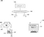
図1は、解析システム100の全体の構成を示す全体概念図である。解析システム100は、例えば乗用車の車体900の塗装表面に発見された塗装ブツの発生原因を解析する解析システムである。塗装ブツは、塗装表面に突起として現れる塗装欠陥であり、塗装中に塵埃が付着したり、塗料中に気泡が混入したりすることによって発生する。解析システム100は、発見された塗装ブツがどのような原因によって発生したかを、ニューラルネットワークを利用して判定する。
FIG. 1 is an overall conceptual diagram showing the overall configuration of the
オペレータOPは、塗装工程を完了した車体900、あるいは塗装工程中の車体900を観察して塗装ブツ901を発見すると、その表面を軽く削って、入力端末110のカメラで当該塗装ブツを撮影する。オペレータOPは、入力端末110を操作して、撮影した画像の画像データを、無線通信を介してシステムサーバ120へ送信する。
When the operator OP observes the
システムサーバ120は、インターネット190と接続されており、無線ルータ150を介して当該画像データを取得する。システムサーバ120は、塗装ブツが発生した発生原因を解析する解析装置として、画像中に写る塗装ブツの発生原因を、学習済みニューラルネットワークを用いて判定する。そして、判定した発生原因に関する情報を、インターネット190および無線ルータ150を介して出力端末130へ出力する。
The
出力端末130は、システムサーバ120から受信した発生原因に関する情報を、表示モニタ131へ表示する。塗装管理者は、システムサーバ120で判定された発生原因を、表示モニタ131を通じて認識することができる。
The
なお、システムサーバ120を中核とする解析システム100の構成は、さまざまに構成し得る。発生原因に関する情報を入力端末110の表示画面に表示するようにしても良いし、有線通信でシステムサーバ120と出力端末130を結んでも良い。また、インターネット190を仲介させず、限定的なネットワークを用いることにより解析システム100を外部のネットワークに対して遮断するように構成しても良い。また、オペレータOPが入力端末110を操作して塗装ブツ901を撮影するのではなく、自動撮影システムを構築して塗装ブツ901を撮影するようにしても良い。表層を削る工程も、自動化しても良い。また、画像データを蓄積する画像サーバを別個に組み込んでも良い。
The configuration of the
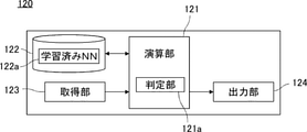
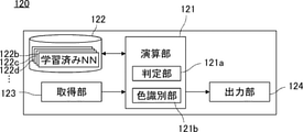
システムサーバ120について説明する。図2は、システムサーバ120の構成を示すブロック図である。システムサーバ120は、主に、演算部121、記憶部122、取得部123、および出力部124によって構成されている。
The
演算部121は、例えばCPUであり、システムサーバ120全体の制御とさまざまな演算処理とを担う。記憶部122は、例えばハードディスクドライブであり、演算部121が実行するソフトウェアプログラムの他、学習済みニューラルネットワーク122a(以下、「学習済みNN122a」などと記す)を記憶している。
The
取得部123は、インターネット190と接続するための通信インターフェースを含む。通信インターフェースは、例えば無線LANユニットである。取得部123は、判定対象となる塗装ブツを撮影した判定画像データを取得して、演算部121へ引き渡す。
The
演算部121は、判定画像データを取得部123から受け取ると、記憶部122から学習済みNN122aを読み出す。演算部121が担う機能実行部としての判定部121aは、判定画像データを学習済みNN122aに入力して、判定対象の塗装面に発生した塗装ブツの発生原因を判定し、出力部124へ引き渡す。
When the
出力部124は、インターネット190と接続するための通信インターフェースを含む。出力部124は、取得部123の通信インターフェースを共用しても良い。出力部124は、判定部121aによって判定された発生原因に関する情報を、出力端末130へ出力する。
The
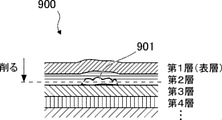
図3は、塗装ブツ901が発生した表面近傍の断面拡大図である。車体900の塗装は、素地に対して数層に亘って重ねて行われる。図示するように、外界に面する表層を第1層とすると、第1層より第2層、第2層より第3層が素地に近い塗装層であり、より以前の塗装工程で塗装された層である。ここで、例えば第2層の塗装工程中に塵埃が付着して塗装ブツ901が発生すると、第2層、第1層の塗装面が隆起して塗装不良となる。
FIG. 3 is an enlarged cross-sectional view of the vicinity of the surface where the
本実施形態における学習済みNN122aは、塗装面に発生した塗装ブツに対し積層された塗装層の少なくとも表層を削った表面を撮影した学習画像データと、当該塗装ブツを解析することにより推定された入力データとの組合せを教師データとしてニューラルネットワークに学習させたものである。学習画像データは、図3に示すような塵埃に起因する塗装ブツである場合には、破線で示す深さまで削って塵埃を表出させた表面を撮影したものであると良い。表層を削っただけでも、塗装ブツの特徴を画像として取り込みやすくなるが、塵埃が表出した状態の画像であれば、より効果的に学習させることができ、ひいては発生原因の判定精度を向上させることができる。 The trained NN122a in the present embodiment is an input estimated by analyzing the learned image data obtained by photographing at least the surface of the painted layer laminated on the painted surface with respect to the painted lumps generated on the painted surface and the surface of the painted lumps. The combination with the data is trained by the neural network as teacher data. In the case of paint lumps caused by dust as shown in FIG. 3, the training image data is preferably a photograph of the surface on which the dust is exposed by scraping to the depth shown by the broken line. Even if the surface layer is scraped off, it will be easier to capture the characteristics of the painted stuff as an image, but if the image is in a state where dust is exposed, it can be learned more effectively, and by extension, the accuracy of determining the cause of occurrence is improved. be able to.
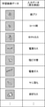
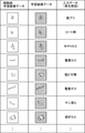
図4は、教師データについて説明する図である。ニューラルネットワークの学習段階においては、まず、例えば熟練者が、それぞれの学習画像データの画像を確認しながら、自らの知識や経験に基づいて推測する塗装ブツの発生原因を端末に入力していく。このように入力された入力データは、当該学習画像データと組み合わされて、教師データを形成する。そして、学習画像データを入力情報、組み合わされた入力データを出力の正解として、ニューラルネットワークに教師あり学習を行わせる。 FIG. 4 is a diagram illustrating teacher data. In the learning stage of the neural network, for example, a skilled person inputs to the terminal the cause of the paint lumps that is inferred based on his / her own knowledge and experience while checking the image of each learning image data. The input data input in this way is combined with the training image data to form teacher data. Then, the neural network is made to perform supervised learning by using the learning image data as input information and the combined input data as the correct answer of the output.
少なくとも表層を削った表面を撮影した学習画像は、図示するようにその形状や表出の仕方などは多様である。熟練者は、それぞれの画像に対して例えば「鉄ブツ」「コート剤」「中PHカス」などと、推定される発生原因を対応させていく。このように形成された教師データを一定数用意してニューラルネットワークに学習させることにより、学習済みNN122aが生成される。生成された学習済みNN122aは、システムサーバ120の記憶部122に移されて実用に供される。なお、熟練者の知識や経験に頼らず、科学的な分析に基づいて発生原因を特定し、学習画像データに対応付けても良い。
As shown in the figure, the learning images obtained by photographing at least the surface of the scraped surface have various shapes and appearance methods. The expert associates each image with, for example, "iron lumps", "coating agent", "medium PH residue", and the presumed cause of occurrence. By preparing a certain number of teacher data thus formed and training the neural network, the trained NN122a is generated. The generated learned NN122a is transferred to the
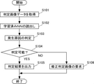
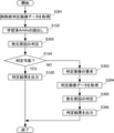
次に、システムサーバ120が実行する処理について説明する。図5は、システムサーバ120の処理フローを示すフロー図である。
Next, the process executed by the
取得部123は、ステップS101で、判定対象の塗装面が撮影された判定画像データを取得する。判定画像データは、上述の学習画像データと同様に、塗装ブツ上の少なくとも表層を削った表面を撮影した画像データである。取得部123は、取得した判定画像データを判定部121aへ引き渡す。
In step S101, the
判定部121aは、ステップS102で、記憶部122から学習済みNN122aを読み出す。そして、ステップS103で、読み出した学習済みNN122aに取得した判定画像データを入力して、塗装ブツの発生原因を判定する。
The
判定部121aは、ステップS104で、塗装ブツの発生原因を判定できたか否かを確認する。判定部は、予め定められた判定基準を満たす判定を行えたか否かにより、塗装ブツの発生原因を判定できたか否かを確認する。例えば、学習済みNN122aの出力として用意されたカテゴリ(発生原因)のいずれもが、予め定められた閾値となる確率(例えば75%)を上回らなかった場合には、発生原因を判定できなかったものとする。
The
ステップS104で判定できたと確認された場合には、ステップS105へ進み、判定部121aは、出力部124へ判定した発生原因を引き渡し、出力部124は、当該情報を出力端末130へ出力する。通信が確立されていないなどの理由により出力端末130へ出力できない場合等においては、当該情報を記憶部122へ記憶させても良い。
If it is confirmed that the determination can be made in step S104, the process proceeds to step S105, the
ステップS104で判定できなかったと確認された場合には、ステップS106へ進み、判定部121aは、判定対象の塗装層を更に削った表面を撮影した判定画像データが必要であるとの判定を行い、出力部124へその旨を引き渡す。出力部124は、当該情報を出力端末130へ出力する。ステップS105またはステップS106の処理が完了したら、一連の処理を終了する。
If it is confirmed that the determination could not be made in step S104, the process proceeds to step S106, and the
以上のように、塗装管理者は、塗装欠陥の表面を削るという単純な作業を経て得られた画像データをシステムサーバ120へ送るだけで、塗装ブツの発生原因を認識することができる。一定数の教師データを用意して学習済みNN122aの判定精度を高めれば、塗装ブツの発生原因を精度良く、容易かつ短時間に解析できる解析装置を実現できる。ひいては、塗装工程の見直しを短時間に行うことができ、塗装工程における歩留まり向上にも寄与する。
As described above, the paint manager can recognize the cause of the paint lumps only by sending the image data obtained through the simple work of scraping the surface of the paint defect to the
次に、いくつかの変形例について説明する。図6は、第1の変形例に係るシステムサーバの構成を示すブロック図である。第1の変形例に係るシステムサーバ120は、演算部121が機能実行部として色識別部121bを有する点、および、記憶部122が複数の学習済みNN122b、122c、122d…を記憶している点において、図2に示したシステムサーバ120と異なる。
Next, some modifications will be described. FIG. 6 is a block diagram showing a configuration of a system server according to the first modification. In the
本変形例においては、表層の塗装色ごとに学習済みニューラルネットワークが用意されている。例えば、学習済みNN122bは、表層が赤色の塗装面である塗装ブツを撮影した学習画像データによる教師データで学習した学習済みニューラルネットワークであり、学習済みNN122cは、表層が青色の塗装面である塗装ブツを撮影した学習画像データによる教師データで学習した学習済みニューラルネットワークである。 In this modification, a trained neural network is prepared for each paint color of the surface layer. For example, the trained NN122b is a trained neural network learned by the teacher data based on the training image data obtained by photographing the painted surface whose surface layer is a red painted surface, and the trained NN122c is a painted surface whose surface layer is a blue painted surface. It is a trained neural network learned by the teacher data by the learning image data which photographed the thing.
色識別部121bは、判定画像データを解析し、判定対象の表層の塗装色が何色であるかを識別する。色識別部121bは、例えば、削られていない周辺画像領域を抽出して色識別を行う。識別した塗装色は、判定部121aへ引き渡される。
The
判定部121aは、記憶部122に記憶されている複数の学習済みNN122b、122c、122d…のうち、色識別部121bが識別した塗装色に対応する学習済みNNを読み出し、その学習済みNNを用いて判定対象の塗装面に発生した塗装ブツの発生原因を判定する。
The
図7は、第1の変形例に係るシステムサーバ120の処理フローを示すフロー図である。図5で示したフローと実質的に同じ処理を実行するフローには同じ符番を付し、特に言及しない限りその説明を省略する。
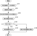
FIG. 7 is a flow chart showing a processing flow of the
ステップS101で、取得部123が判定画像データを色識別部121bへ引き渡すと、ステップS201へ進み、色識別部121bは、上述のように、判定対象の表層の塗装色が何色であるかを識別し、判定部121aへ引き渡す。ステップS202へ進み、判定部121aは、上述のように、記憶部122に記憶されている複数の学習済みNN122b、122c、122d…のうち、色識別部121bが識別した塗装色に対応する学習済みNNを読み出す。ステップS103へ進み、判定部121aは、ステップS202で読み出した特定の学習済みNNを用いて、判定対象の塗装面に発生した塗装ブツの発生原因を判定する。本変形例のように、塗装色ごとに学習済みニューラルネットワークを構築して選択的に用いれば、塗装ブツの発生原因を更に精度良く判定することができる。
When the
次に第2の変形例について説明する。図8は、第2の変形例に係る教師データについて説明する図である。第2の変形例における学習済みNNは、塗装層を削る前の表面を撮影した削除前学習画像データも含めて学習している点において、図4を用いて説明した教師データによって生成した学習済みNNと異なる。 Next, a second modification will be described. FIG. 8 is a diagram illustrating teacher data according to the second modification. The trained NN in the second modification is trained by the teacher data described with reference to FIG. 4 in that it is trained including the pre-deletion training image data obtained by photographing the surface before scraping the coating layer. Different from NN.
第2の変形例におけるニューラルネットワークの学習段階においては、まず、例えば熟練者が、それぞれの削除前学習画像データの画像または学習画像データの画像、あるいはその両方の画像を確認しながら、自らの知識や経験に基づいて推測する塗装ブツの発生原因を端末に入力していく。このように入力された入力データは、当該削除前学習画像データおよび学習画像データと組み合わされて、教師データを形成する。そして、第一段階として削除前学習画像データを入力情報、組み合わされた入力データを出力の正解として、ニューラルネットワークに教師あり学習を行わせる。さらに第二段階として学習画像データを入力情報、組み合わされた入力データを出力の正解として、ニューラルネットワークに教師あり学習を行わせる。なお、熟練者の知識や経験に頼らず、科学的な分析に基づいて発生原因を特定し、削除前学習画像データおよび学習画像データに対応付けても良い。 In the learning stage of the neural network in the second modification, for example, an expert checks his / her own knowledge while checking the image of each pre-deletion training image data and / or the image of the training image data. And input the cause of the paint lumps to be guessed based on experience to the terminal. The input data thus input is combined with the pre-deletion training image data and the training image data to form teacher data. Then, as the first step, the neural network is made to perform supervised learning by using the pre-deletion learning image data as input information and the combined input data as the correct answer of the output. Furthermore, as the second step, the neural network is made to perform supervised learning by using the learning image data as input information and the combined input data as the correct answer for output. It should be noted that the cause may be identified based on scientific analysis and associated with the pre-deletion learning image data and the learning image data without relying on the knowledge and experience of an expert.
生成された学習済みNNは、システムサーバ120の記憶部122に移されて実用に供される。このように生成された学習済みNNは、2段階の判定段階を有する。すなわち、削除前の判定画像データを入力画像データとして受け付けて確からしい発生原因が判定できた場合には、その判定結果を出力する。確からしい発生原因が判定できなかった場合には、削除後の判定画像データを入力画像データとして受け付けて、より精度の高い判定を行う。
The generated learned NN is transferred to the
このように学習済みNNを構成すれば、判定したい塗装表面を削らなくても簡易的に判定結果を得ることができる。したがって、オペレータOPは、まずは、塗装表面を削る前の削除前判定画像データを用意すれば良く、塗装表面を削る作業の手間や時間を削減することができる。また、簡易的な判定では一定の精度を確保できない場合には、オペレータOPは、塗装表面を削った後の判定画像データを用意し、学習済みNNは、当該削除後の判定画像データを受け取って再判定する。このような再判定を行うことにより判定精度も担保できる。すなわち、このような学習済みNNを利用すれば、作業の効率化と判定精度の確保を両立させることができる。 If the trained NN is configured in this way, the determination result can be easily obtained without scraping the painted surface to be determined. Therefore, the operator OP may first prepare the pre-deletion determination image data before scraping the painted surface, and can reduce the labor and time of the work of scraping the painted surface. If a certain degree of accuracy cannot be ensured by a simple judgment, the operator OP prepares the judgment image data after scraping the painted surface, and the learned NN receives the judgment image data after the deletion. Re-judgment. By performing such a re-judgment, the judgment accuracy can be guaranteed. That is, if such a learned NN is used, it is possible to achieve both work efficiency and determination accuracy.
図9は、第2の変形例に係るシステムサーバ120の処理フローを示すフロー図である。図5で示したフローと実質的に同じ処理を実行するフローには同じ符番を付し、特に言及しない限りその説明を省略する。
FIG. 9 is a flow chart showing a processing flow of the
取得部123は、ステップS301で、判定対象の塗装面が撮影された削除前判定画像データを取得する。削除前判定画像データは、塗装ブツ上の表層に対して削る作業が行われる前の表面を撮影した画像データである。取得部123は、取得した判定画像データを判定部121aへ引き渡す。
In step S301, the
ステップS102を経てステップS302では、読み出した学習済みNN122に取得した削除前判定画像データを入力して、塗装ブツの発生原因を判定する。そして、ステップS104へ進み、YESと確認されてステップS105へ進んだ場合には、削除前判定画像データで確からしい発生原因が判定できたものとして、一連の処理を終了する。 In step S302 through step S102, the acquired pre-deletion determination image data is input to the read-out learned NN122, and the cause of the occurrence of paint lumps is determined. Then, if the process proceeds to step S104, and if YES is confirmed and the process proceeds to step S105, it is assumed that the probable cause of occurrence can be determined from the pre-deletion determination image data, and the series of processes is terminated.
ステップS104でNOと確認された場合には、ステップS303へ進む。判定部121aは、ステップS303で、塗装ブツ上の少なくとも表層を削った表面を撮影した画像データである判定画像データが必要であるとの判定を行い、出力部124へその旨を引き渡す。出力部124は、当該情報を出力端末130へ出力する。
If NO is confirmed in step S104, the process proceeds to step S303. In step S303, the
取得部123は、ステップS304で、判定画像データを取得して判定部121aへ引き渡す。判定部121aは、続くステップS305で、学習済みNN122に取得した削除前判定画像データを入力して、塗装ブツの発生原因を判定する。判定部121aは、ステップS306で、出力部124へ判定した発生原因を引き渡し、出力部124は、当該情報を出力端末130へ出力して、一連の処理を終了する。
In step S304, the
なお、ステップS305の判定結果の確からしさを更に確認して、図5におけるステップS106のように、修正判定画像を要求しても構わない。また、第2の変形例においても、第1の変形例のように、塗装色ごとに学習済みNNを用意し、取得部が取得した画像データから識別される塗装色に応じて学習済みNNを読み出すようにしても良い。 It should be noted that the accuracy of the determination result in step S305 may be further confirmed, and the correction determination image may be requested as in step S106 in FIG. Further, also in the second modification, as in the first modification, the trained NN is prepared for each paint color, and the trained NN is prepared according to the paint color identified from the image data acquired by the acquisition unit. You may read it.
各変形例を含め本実施形態においては、入力情報として画像データを利用する例を説明したが、画像データに加えて他の情報を教師データおよび判定用データに加えても良い。例えば、塗装環境の温度情報、湿度情報、塗装が行われた時刻情報も、判定精度を向上させる付加情報として利用できる。 In the present embodiment including each modification, an example of using image data as input information has been described, but other information may be added to the teacher data and the determination data in addition to the image data. For example, temperature information, humidity information, and time information when painting is performed in the painting environment can also be used as additional information for improving the determination accuracy.
また、図4等において示した塗装ブツが発生した発生原因は例示であって、もちろん他の発生原因を判定対象に加えても良い。また、学習画像データは、一つの発生原因に対して多数用意されることが好ましい。塗装ブツは、塵埃や気泡に限らず、別塗料の混入や油分の飛散などによっても生じ得る。 Further, the cause of occurrence of the coating lumps shown in FIG. 4 and the like is an example, and of course, other causes of occurrence may be added to the determination target. Further, it is preferable that a large number of learning image data are prepared for one cause of occurrence. Painting lumps are not limited to dust and air bubbles, but can also be caused by mixing of another paint or scattering of oil.
また、塗装ブツが画像に対して一定の大きさとなるように、塗装表面に対する画角を一定に保つためのカメラ治具等を利用しても良い。この場合、同種の塗装ブツであれば、画像領域に対しておよそ一定の大きさとなるので、発生原因の判定精度向上にも寄与する。 Further, a camera jig or the like for keeping the angle of view with respect to the painted surface may be used so that the painted lumps have a constant size with respect to the image. In this case, if the paint is of the same type, the size is approximately constant with respect to the image area, which also contributes to improving the accuracy of determining the cause of occurrence.
100 解析システム、110 入力端末、120 システムサーバ、121 演算部、121a 判定部、121b 色識別部、122 記憶部、122a 学習済みNN、123 取得部、124 出力部、130 出力端末、131 表示モニタ、150 無線ルータ、190 インターネット、900 車体、901 塗装ブツ 100 analysis system, 110 input terminal, 120 system server, 121 calculation unit, 121a judgment unit, 121b color identification unit, 122 storage unit, 122a learned NN, 123 acquisition unit, 124 output unit, 130 output terminal, 131 display monitor, 150 wireless router, 190 internet, 900 car body, 901 painted stuff
Claims (7)
学習対象の塗装面に発生した塗装ブツに対し積層された塗装層の少なくとも表層を削った表面を撮影した学習画像データと、当該塗装ブツを解析することにより推定された入力データとの組合せを教師データとして学習した学習済みニューラルネットワークを記憶した記憶部と、
判定対象の塗装面に発生した塗装ブツに対し積層された塗装層の少なくとも表層を削った表面を撮影した判定画像データを取得する取得部と、
前記取得部が取得した前記判定画像データを前記記憶部から読み出した前記学習済みニューラルネットワークに入力して、前記判定対象の塗装面に発生した塗装ブツの発生原因を判定する判定部と、
前記判定部によって判定された発生原因に関する情報を出力する出力部と
を備える解析装置。 It is an analysis device that analyzes the cause of the occurrence of paint lumps, which are paint defects that appear as protrusions on the painted surface.
The teacher teaches the combination of the learning image data obtained by photographing at least the surface of the painted layer laminated on the painted surface generated on the painted surface to be learned and the input data estimated by analyzing the painted lumps. A storage unit that stores the trained neural network learned as data,
An acquisition unit that acquires judgment image data obtained by photographing at least the surface of the coating layer laminated on the coating surface generated on the judgment target, with the surface layer scraped off.
A determination unit that inputs the determination image data acquired by the acquisition unit to the trained neural network read from the storage unit to determine the cause of paint bumps generated on the coating surface to be determined.
An analysis device including an output unit that outputs information on the cause of occurrence determined by the determination unit.
前記判定部は、前記取得部が取得した前記判定画像データが示す塗装色に基づいて、前記判定画像データを入力する前記学習済みニューラルネットワークを選択する請求項1から3のいずれか1項に記載の解析装置。 The storage unit stores a plurality of the learned neural networks for each paint color.
The determination unit is described in any one of claims 1 to 3 for selecting the trained neural network for inputting the determination image data based on the paint color indicated by the determination image data acquired by the acquisition unit. Analytical device.
前記取得部は、判定対象の前記塗装層を削っていない表面を撮影した削除前判定画像データを取得し、
前記判定部は、前記取得部が取得した前記削除前判定画像データを前記記憶部から読み出した前記学習済みニューラルネットワークに入力して、前記判定対象の塗装面に発生した塗装ブツの発生原因を判定する請求項1から4のいずれか1項に記載の解析装置。 The teacher data includes pre-deletion learning image data obtained by photographing the surface before scraping the coating layer.
The acquisition unit acquires pre-deletion determination image data obtained by photographing the surface of the coating layer to be determined without scraping.
The determination unit inputs the pre-deletion determination image data acquired by the acquisition unit into the trained neural network read from the storage unit, and determines the cause of the coating lumps generated on the coating surface to be determined. The analysis device according to any one of claims 1 to 4.
前記判定部は、前記取得部が取得した前記判定画像データを前記学習済みニューラルネットワークに入力して、前記判定対象の塗装面に発生した塗装ブツの発生原因を判定する請求項5に記載の解析装置。 The acquisition unit acquires the determination image data when the determination unit cannot determine the cause of the occurrence.
The analysis according to claim 5, wherein the determination unit inputs the determination image data acquired by the acquisition unit into the trained neural network, and determines the cause of the coating lumps generated on the coating surface to be determined. Device.
判定対象の塗装面に発生した塗装ブツに対し積層された塗装層の少なくとも表層を削った表面を撮影した判定画像データを取得する取得ステップと、
学習対象の塗装面に発生した塗装ブツに対し積層された塗装層の少なくとも表層を削った表面を撮影した学習画像データと、当該塗装ブツを解析することにより推定された入力データとの組合せを教師データとして学習した学習済みニューラルネットワークを記憶部から読み出す読出しステップと、
前記取得ステップで取得した前記判定画像データを前記記憶部から読み出した前記学習済みニューラルネットワークに入力して、前記判定対象の塗装面に発生した塗装ブツの発生原因を判定する判定ステップと、
前記判定ステップによって判定された発生原因に関する情報を出力する出力ステップと
をコンピュータに実行させる解析プログラム。 It is an analysis program that analyzes the cause of the occurrence of paint lumps, which are paint defects that appear as protrusions on the painted surface.
The acquisition step of acquiring the judgment image data obtained by photographing at least the surface of the painted layer laminated on the painted surface generated on the judgment target painted surface and scraping the surface layer.
The teacher teaches the combination of the learning image data obtained by photographing at least the surface of the painted layer laminated on the painted surface generated on the painted surface to be learned and the input data estimated by analyzing the painted lumps. A read step to read the learned neural network learned as data from the storage unit,
A determination step in which the determination image data acquired in the acquisition step is input to the trained neural network read from the storage unit to determine the cause of the coating lumps generated on the coating surface to be determined.
An analysis program that causes a computer to execute an output step that outputs information about the cause of occurrence determined by the determination step.
Priority Applications (3)
| Application Number | Priority Date | Filing Date | Title |
|---|---|---|---|
| JP2018087114A JP6996413B2 (en) | 2018-04-27 | 2018-04-27 | Analytical equipment and analysis program |
| US16/375,194 US10533849B2 (en) | 2018-04-27 | 2019-04-04 | Analysis apparatus and analysis program |
| CN201910338474.XA CN110428393B (en) | 2018-04-27 | 2019-04-25 | Analysis device and analysis program |
Applications Claiming Priority (1)
| Application Number | Priority Date | Filing Date | Title |
|---|---|---|---|
| JP2018087114A JP6996413B2 (en) | 2018-04-27 | 2018-04-27 | Analytical equipment and analysis program |
Publications (2)
| Publication Number | Publication Date |
|---|---|
| JP2019192131A JP2019192131A (en) | 2019-10-31 |
| JP6996413B2 true JP6996413B2 (en) | 2022-01-17 |
Family
ID=68291437
Family Applications (1)
| Application Number | Title | Priority Date | Filing Date |
|---|---|---|---|
| JP2018087114A Expired - Fee Related JP6996413B2 (en) | 2018-04-27 | 2018-04-27 | Analytical equipment and analysis program |
Country Status (3)
| Country | Link |
|---|---|
| US (1) | US10533849B2 (en) |
| JP (1) | JP6996413B2 (en) |
| CN (1) | CN110428393B (en) |
Families Citing this family (11)
| Publication number | Priority date | Publication date | Assignee | Title |
|---|---|---|---|---|
| JP7217256B2 (en) * | 2020-01-10 | 2023-02-02 | 株式会社大気社 | Quality control system, quality control method and quality control program |
| JP6811881B1 (en) | 2020-01-10 | 2021-01-13 | 株式会社大気社 | Quality management system and quality control program |
| DE102020000412A1 (en) * | 2020-01-24 | 2021-07-29 | bdtronic GmbH | Dosing device and method for the dosed delivery of a medium |
| JP7337002B2 (en) * | 2020-02-07 | 2023-09-01 | 株式会社電通 | Fish quality judgment system |
| EP3971556A1 (en) * | 2020-09-17 | 2022-03-23 | Evonik Operations GmbH | Qualitative or quantitative characterization of a coating surface |
| JP7173188B2 (en) | 2021-02-26 | 2022-11-16 | 株式会社安川電機 | COATING CONTROL DEVICE, COATING CONTROL SYSTEM, SETTING DEVICE, CONTROL METHOD, AND PROGRAM FOR COATING CONTROL DEVICE |
| JP7255617B2 (en) | 2021-02-26 | 2023-04-11 | 株式会社安川電機 | painting control system |
| JP7669883B2 (en) | 2021-09-08 | 2025-04-30 | トヨタ自動車株式会社 | Inspection device, inspection method, and program |
| JP2023066489A (en) * | 2021-10-29 | 2023-05-16 | 株式会社安川電機 | Evaluation system, evaluation method, and evaluation program |
| JP7553851B1 (en) * | 2023-03-29 | 2024-09-19 | ダイキン工業株式会社 | Paint inspection system and paint inspection support system |
| KR102850431B1 (en) * | 2024-07-31 | 2025-08-27 | (주)동주 | Device and system that control the defect rate of painted products using artificial intelligence algorithms |
Citations (1)
| Publication number | Priority date | Publication date | Assignee | Title |
|---|---|---|---|---|
| JP2005118757A (en) | 2003-10-20 | 2005-05-12 | Kansai Paint Co Ltd | Coating defect analyzing system, coating defect analyzing method and computer program |
Family Cites Families (11)
| Publication number | Priority date | Publication date | Assignee | Title |
|---|---|---|---|---|
| JP3443873B2 (en) * | 1992-09-16 | 2003-09-08 | 日産自動車株式会社 | Automotive coating condition management device |
| US6532066B1 (en) * | 2000-08-05 | 2003-03-11 | Ford Global Technologies, Inc. | Vision system for identification of defects in wet polymeric coatings |
| EP2660310A4 (en) * | 2010-12-28 | 2015-09-30 | Tashiro Kei | Comprehensive glaucoma determination method utilizing glaucoma diagnosis chip and deformed proteomics cluster analysis |
| JP5790446B2 (en) | 2011-11-28 | 2015-10-07 | 富士通株式会社 | Surface defect inspection method and surface defect inspection apparatus |
| US20150035970A1 (en) * | 2013-08-02 | 2015-02-05 | Applied Vision Corporation | Systems and methods to detect coating voids |
| JP6170860B2 (en) * | 2014-03-25 | 2017-07-26 | 株式会社日立情報通信エンジニアリング | Character recognition device and identification function generation method |
| ES2917217T3 (en) * | 2016-01-07 | 2022-07-07 | Arkema Inc | Optical method to measure the thickness of coatings deposited on substrates |
| US10189479B2 (en) * | 2016-04-06 | 2019-01-29 | At&T Intellectual Property I, L.P. | Methods and apparatus for vehicle operation analysis |
| CN106097335B (en) * | 2016-06-08 | 2019-01-25 | 安翰光电技术(武汉)有限公司 | Alimentary canal lesion image identification system and recognition methods |
| US9947102B2 (en) * | 2016-08-26 | 2018-04-17 | Elekta, Inc. | Image segmentation using neural network method |
| JP6829575B2 (en) * | 2016-10-03 | 2021-02-10 | グローリー株式会社 | Image processing equipment, image processing system and image processing method |
-
2018
- 2018-04-27 JP JP2018087114A patent/JP6996413B2/en not_active Expired - Fee Related
-
2019
- 2019-04-04 US US16/375,194 patent/US10533849B2/en active Active
- 2019-04-25 CN CN201910338474.XA patent/CN110428393B/en not_active Expired - Fee Related
Patent Citations (1)
| Publication number | Priority date | Publication date | Assignee | Title |
|---|---|---|---|---|
| JP2005118757A (en) | 2003-10-20 | 2005-05-12 | Kansai Paint Co Ltd | Coating defect analyzing system, coating defect analyzing method and computer program |
Non-Patent Citations (1)
| Title |
|---|
| KAMANI, P. et al.,Automatic Paint Defect Detection and Classification of Car Body,2011 7th Iranian Conference on Machine Vision and Image Processing,IEEE,2011年,インターネット,<URL: https://ieeexplore.ieee.org/document/6121575>,[検索日 2021.11.11] |
Also Published As
| Publication number | Publication date |
|---|---|
| JP2019192131A (en) | 2019-10-31 |
| CN110428393B (en) | 2022-12-13 |
| US10533849B2 (en) | 2020-01-14 |
| US20190331483A1 (en) | 2019-10-31 |
| CN110428393A (en) | 2019-11-08 |
Similar Documents
| Publication | Publication Date | Title |
|---|---|---|
| JP6996413B2 (en) | Analytical equipment and analysis program | |
| CA2249140C (en) | Method and apparatus for object detection and background removal | |
| JP7062474B2 (en) | Deterioration status identification device, deterioration status identification method and program | |
| EP2202687A2 (en) | Image quality evaluation device and method | |
| JP7372017B2 (en) | Steel component learning device, steel component estimation device, steel type determination device, steel component learning method, steel component estimation method, steel type determination method, and program | |
| CN112016630A (en) | Training method, device and equipment based on image classification model and storage medium | |
| CN113420871B (en) | Image quality evaluation method, image quality evaluation device, storage medium, and electronic device | |
| CN113888509B (en) | Image clarity evaluation method, device, equipment and storage medium | |
| CN111104910A (en) | Method for monitoring garbage delivery behavior and related products | |
| CN115035842A (en) | LED display screen correction method, system and device and electronic equipment | |
| CN114155211A (en) | Image processing method and device, electronic equipment and storage medium | |
| CN110637227A (en) | A detection parameter determination method and detection device | |
| JP2022034428A (en) | Construction quality evaluation program | |
| CN115131686A (en) | Intelligent power inspection method based on active learning and semi-supervised learning | |
| CN117218125A (en) | Detection methods, equipment, storage media, devices and systems for display screen defects | |
| JP2019075078A (en) | Construction site image determination device and construction site image determination program | |
| CN113284063B (en) | Image processing method, image processing device, electronic device and readable storage medium | |
| CN112581001B (en) | Evaluation method and device of equipment, electronic equipment and readable storage medium | |
| JP2019074774A (en) | Construction site image determination device and construction site image determination program | |
| CN108357193A (en) | Silk-screen detection method, device, terminal device and storage medium | |
| JP2022076750A (en) | Information processing equipment, information processing system, and information processing method | |
| JP2022188933A (en) | Steel fiber dispersion rate estimation system | |
| CN113663327B (en) | Method, device, equipment and storage medium for detecting shielding icon of special-shaped screen | |
| CN113870210B (en) | Image quality assessment method, device, equipment and storage medium | |
| JP2019204185A (en) | Image processing device, robot, and robot system |
Legal Events
| Date | Code | Title | Description |
|---|---|---|---|
| A621 | Written request for application examination |
Free format text: JAPANESE INTERMEDIATE CODE: A621 Effective date: 20201124 |
|
| A977 | Report on retrieval |
Free format text: JAPANESE INTERMEDIATE CODE: A971007 Effective date: 20211108 |
|
| TRDD | Decision of grant or rejection written | ||
| A01 | Written decision to grant a patent or to grant a registration (utility model) |
Free format text: JAPANESE INTERMEDIATE CODE: A01 Effective date: 20211116 |
|
| A61 | First payment of annual fees (during grant procedure) |
Free format text: JAPANESE INTERMEDIATE CODE: A61 Effective date: 20211129 |
|
| R151 | Written notification of patent or utility model registration |
Ref document number: 6996413 Country of ref document: JP Free format text: JAPANESE INTERMEDIATE CODE: R151 |
|
| LAPS | Cancellation because of no payment of annual fees |