JP6995815B2 - Laminating device and laminating method using it - Google Patents
Laminating device and laminating method using it Download PDFInfo
- Publication number
- JP6995815B2 JP6995815B2 JP2019187666A JP2019187666A JP6995815B2 JP 6995815 B2 JP6995815 B2 JP 6995815B2 JP 2019187666 A JP2019187666 A JP 2019187666A JP 2019187666 A JP2019187666 A JP 2019187666A JP 6995815 B2 JP6995815 B2 JP 6995815B2
- Authority
- JP
- Japan
- Prior art keywords
- press plate
- central portion
- press
- heating
- laminating
- Prior art date
- Legal status (The legal status is an assumption and is not a legal conclusion. Google has not performed a legal analysis and makes no representation as to the accuracy of the status listed.)
- Active
Links
Images


Description
本発明は、基材とフィルムとを積層する積層装置に関するものであり、詳細には、基材(例えば、プリント回路基板やウエハ)と樹脂フィルムとからなる積層体を製造するに際し、得られる積層体の厚みをより均一にすることができる積層装置に関するものである。 The present invention relates to a laminating device for laminating a base material and a film, and more specifically, the laminating body obtained when manufacturing a laminated body composed of a base material (for example, a printed circuit board or a wafer) and a resin film. It relates to a laminating device capable of making the thickness of the body more uniform.
従来、配線等によって凹凸が設けられた基材と樹脂フィルムを積層する装置においては、得られた積層体の厚みにばらつきがあると、これらを多層に重ねた際に品質不良の発生や無駄なスペースが生じて嵩高くなるため、得られる積層体の厚みを均一化する様々な工夫がなされている(例えば、特許文献1)。 Conventionally, in a device for laminating a base material and a resin film having irregularities provided by wiring or the like, if the thickness of the obtained laminate varies, quality defects occur or wasteful when these are laminated in multiple layers. Since space is generated and the thickness becomes bulky, various measures have been taken to make the thickness of the obtained laminate uniform (for example, Patent Document 1).
このような工夫の一つとして、樹脂からなるフィルムを加熱したプレス板で押圧する際には、フィルム全面にむらなく熱が伝わるように、通常、上記プレス板の表面温度をできるだけ均一にすることがあげられる。しかし、上記プレス板は、通常、表面積が大きいため、その全面を均一な温度にすることは困難である。 As one of such measures, when a film made of resin is pressed by a heated press plate, the surface temperature of the press plate is usually made as uniform as possible so that heat is evenly transferred to the entire surface of the film. Can be given. However, since the press plate usually has a large surface area, it is difficult to make the entire surface of the press plate a uniform temperature.
このため、プレス板の表面温度が均一になるように設定しても、厳密には均一化が達成されておらず、図8に模式的に示すように、そのプレス板で基材52とフィルム53を押圧して積層体51を製造すると、フィルム53の端部が部分的に基材52からはみ出し(ブリード)が生じることがある。技術の進歩に伴い、ブリードの許容範囲も狭まってきており、フィルム53の端部が基材52からはみ出す部分が少しでも生じると、積層体51におけるフィルム等の厚みの均一性の許容範囲を超えてしまうおそれがある。このため、その対策が強く求められている。
Therefore, even if the surface temperature of the press plate is set to be uniform, the uniformization is not strictly achieved, and as schematically shown in FIG. 8, the
本発明は、このような事情に鑑みなされたもので、押圧時のフィルムの部分的なはみ出しを防止し、フィルム等の厚みの均一性を担保することによって、積層体の厚みの均一化をより厳密に図る積層装置の提供をその目的とする。 The present invention has been made in view of such circumstances, and by preventing partial protrusion of the film at the time of pressing and ensuring the uniformity of the thickness of the film or the like, the thickness of the laminated body can be made more uniform. The purpose is to provide a laminating device that is strictly planned.
上記の目的を達成するため、本発明は、以下の[1]~[8]を要旨とする。
[1]基材およびフィルムを押圧する押圧手段を備えた積層装置であって、上記押圧手段が、進退可能のプレスブロックと、上記プレスブロックに取り付け可能なプレス板と、上記プレス板を加熱可能な複数の熱源と、上記各熱源に対する加熱制御を行うよう設定された制御システムとを有しており、上記複数の熱源が、上記プレス板の中央部と上記中央部を環状に取り囲む周縁部とを個別に加熱しうる配置で設けられている積層装置。
[2]上記プレス板の中央部と周縁部とが互いに異なる温度になるよう加熱制御されるようになっている[1]記載の積層装置。
[3]上記プレス板の中央部と周縁部とが同じ温度になるよう加熱制御されるようになっている[1]記載の積層装置。
[4]上記プレス板の周縁部が複数の区分に分けられており、上記各区分に互いに異なる熱源および制御システムが設けられ、上記熱源に対する加熱制御が区分ごとに可能になっている[1]~[3]のいずれか一項に記載の積層装置。
[5] [1]に記載の積層装置を用いて基材とフィルムとを積層する方法であって、上記複数の熱源によりプレス板を加熱する加熱工程と、上記加熱されたプレス板により基材およびフィルムを押圧する押圧工程とを有し、上記加熱工程において、上記プレス板の中央部と上記中央部を環状に取り囲む周縁部とが、互いに異なる温度に加熱制御される積層方法。
[6]上記加熱工程において、上記プレス板の中央部と周縁部とが0.1~50℃の温度差になるよう加熱制御される[5]記載の積層方法。
[7]上記加熱工程において、上記プレス板の中央部の温度より周縁部の温度が低く設定される[5]または[6]記載の積層方法。
[8] [1]に記載の積層装置を用いて基材とフィルムとを積層する方法であって、上記複数の熱源によりプレス板を加熱する加熱工程と、上記加熱されたプレス板により基材およびフィルムを押圧する押圧工程とを有し、上記加熱工程において、上記プレス板の中央部と上記中央部を環状に取り囲む周縁部とが、同じ温度に加熱制御される積層方法。
In order to achieve the above object, the present invention has the following [1] to [8] as gist.
[1] A laminating device provided with a pressing means for pressing a base material and a film, wherein the pressing means can heat a press block that can move forward and backward, a press plate that can be attached to the press block, and the press plate. It has a plurality of heat sources and a control system set to perform heating control for each of the heat sources, and the plurality of heat sources include a central portion of the press plate and a peripheral portion that surrounds the central portion in an annular shape. A laminating device provided in an arrangement that allows individual heating.
[2] The laminating apparatus according to [1], wherein the central portion and the peripheral portion of the press plate are heated and controlled so as to have different temperatures from each other.
[3] The laminating apparatus according to [1], wherein the central portion and the peripheral portion of the press plate are heated and controlled to have the same temperature.
[4] The peripheral edge of the press plate is divided into a plurality of divisions, and different heat sources and control systems are provided in each division, and heating control for the heat source is possible for each division [1]. The laminating device according to any one of [3].
[5] A method of laminating a base material and a film using the laminating apparatus according to [1], wherein the press plate is heated by the plurality of heat sources and the base material is formed by the heated press plate. A laminating method comprising a pressing step of pressing a film and a heating step in which a central portion of the press plate and a peripheral edge portion surrounding the central portion in an annular shape are heated and controlled to different temperatures.
[6] The laminating method according to [5], wherein in the heating step, heating is controlled so that the central portion and the peripheral portion of the press plate have a temperature difference of 0.1 to 50 ° C.
[7] The laminating method according to [5] or [6], wherein in the heating step, the temperature of the peripheral portion is set lower than the temperature of the central portion of the press plate.
[8] A method of laminating a base material and a film using the laminating apparatus according to [1], wherein the press plate is heated by the plurality of heat sources and the base material is formed by the heated press plate. A laminating method in which a central portion of the press plate and a peripheral edge portion that surrounds the central portion in an annular shape are heated and controlled to the same temperature in the heating step, which comprises a pressing step of pressing the film.
すなわち、本発明の発明者らは、前記課題を解決するために研究を重ねた。その結果、樹脂等からなるフィルムの厚みを均一にするためには、プレス板表面の温度を中央部と周縁部とに分けて厳密に制御することが必要であることを見い出し、本発明に到達した。 That is, the inventors of the present invention have repeated research in order to solve the above-mentioned problems. As a result, it was found that in order to make the thickness of the film made of resin or the like uniform, it is necessary to strictly control the temperature of the surface of the press plate separately for the central portion and the peripheral portion, and reached the present invention. did.
本発明の積層装置によれば、押圧時のフィルムのはみ出しを防止でき、フィルムの厚みの均一性を担保することができる。これにより、得られる積層体の厚みの均一化を図ることができる。 According to the laminating device of the present invention, it is possible to prevent the film from sticking out at the time of pressing, and it is possible to ensure the uniformity of the film thickness. Thereby, it is possible to make the thickness of the obtained laminated body uniform.
つぎに、本発明を実施するための形態について詳しく説明する。ただし、本発明は、以下の実施の形態に限定されるものではない。 Next, a mode for carrying out the present invention will be described in detail. However, the present invention is not limited to the following embodiments.
図1は、本発明の1つの実施の形態に係る積層装置Iを示している。この積層装置Iは、ビルドアップ基板用の基材と、ラミネート用のフィルムとを積層するための装置であり、上側のプレス板1および下側のプレス板2の間に、上記基材およびフィルム(これらを「ワーク50」とすることがある)を配置し、上側の熱盤3により加熱された上記プレス板1および下側の熱盤4により加熱されたプレス板2でワーク50を加熱押圧して、基材とフィルムとが一体化した積層体を製造するものである。
FIG. 1 shows a laminating device I according to one embodiment of the present invention. The laminating device I is a device for laminating a base material for a build-up substrate and a film for laminating, and is a device for laminating the base material and the film between the
この実施の形態では、プレス台12に立設された複数本(図1では、2本しか図示せず)の支柱10と、これら各支柱10にボルト,ナット等の固定手段で固定される上側のプレスブロック6と、上記各支柱10に上下移動可能(進退可能)に取り付けられる下側のプレスブロック7等を備えている。この下側のプレスブロック7は、ボールねじ11を介してサーボモータ5に連結されており、このサーボモータ5の作動により(ボールねじ11におけるシャフト回転に伴うナットの上昇および下降に伴って)上下移動(進退)が可能になっている。なお、符号8は、上側のプレス板1と熱盤3との間に配置される緩衝材であり、符号9は、下側のプレス板2と熱盤4との間に配置される緩衝材である。
上側のプレスブロック6および下側のプレスブロック7は、基本的な構成が共通するため、以下、下側のプレスブロック7を代表して説明する。
In this embodiment, a plurality of columns 10 (only two are shown in FIG. 1) erected on the press table 12 and an upper side fixed to each of these
Since the
上記プレス板2は、押圧時にワーク50に当接するものであり、耐熱性を考慮して、通常、金属からなるものが用いられる。このような金属としては、例えば、ステンレス、鉄、アルミニウム、これらの合金等があげられ、耐錆性に優れる点からステンレスが好ましく用いられる。また、上記プレス板2として、フレキシブル性を有する金属板が好ましく用いられる。このようなフレキシブル金属板を上記プレス板2として用いる場合の厚みは、通常、0.1~10mmであり、好ましくは1~3mmである。上記フレキシブル金属板の厚みが好ましい範囲にあると、得られる積層体の厚みをより均一にできる。さらに、上記プレス板2の表面が鏡面に研磨されていると、得られる積層体の厚みをより均一にできるため好ましい。
The
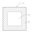
上記プレスブロック7に配置されるプレス板2は、図2にその平面図を示すとおり、中央部A(図2で破線で囲って示す中央部分)とこの中央部Aを環状に取り囲む周縁部B(図2で斜線を引いて示す周縁部分)とを個別に加熱しうる熱盤によって加熱されるようになっており、上記積層装置Iは、上記熱盤に備えられた各熱源に対する加熱制御を行うよう設定された複数の制御システムを有している。これらの点が本発明の最大の特徴である。
As shown in the plan view of FIG. 2, the
すなわち、上記構成によると、上記プレス板2の中央部Aとこれを環状に取り囲む周縁部Bとを異なる温度になるよう加熱制御することが可能になる。その結果、押圧時において、フィルムの粘度を周縁部と中央部とで異なるようにすることができ、例えば、フィルムの周縁部の粘度を中央部の粘度より低くすると、この周縁部自体がいわばストッパーとなるため、フィルムのはみ出しを効果的に抑制することができる。
一方、上記構成は、上記プレス板2の中央部Aとこれを環状に取り囲む周縁部Bとを同じ温度になるよう加熱制御することも容易になる。上記プレス板2の周縁部Bは上記中央部Aに比べて外気(積層装置Iの設置雰囲気)温度の影響を受けやすく、熱も逃げやすいという特性を有しており、上記プレス板2全体の温度をより厳密に均一にするには、上記中央部Aに対する加熱の程度と上記周縁部Bに対する加熱の程度とを相違させる必要があるためである。
That is, according to the above configuration, it is possible to control the heating of the central portion A of the
On the other hand, in the above configuration, it is also easy to control the heating so that the central portion A of the
したがって、本発明の積層装置は、複雑な構成とすることなく、加熱温度の制御によって押圧時のフィルムのはみ出しを効果的に防止することができ、厚みの均一化が図られた高品質の積層体を低コストで製造することができる。なお、本発明における制御システムには、加熱温度を制御する一連の機器とこれらの制御プログラムとが含まれる。 Therefore, the laminating device of the present invention can effectively prevent the film from sticking out at the time of pressing by controlling the heating temperature without complicated configuration, and high-quality laminating with uniform thickness. The body can be manufactured at low cost. The control system in the present invention includes a series of devices for controlling the heating temperature and these control programs.
下側のプレス板2の表面を、図2に示すように特定の範囲で異なる温度にするためには、例えば、図3に示す熱盤4を用いることで実現することができる。上記熱盤4は、上記プレス板2に緩衝材9(図1参照)を介して重ねて配置されるものであり、熱源である複数(この例では12本)のカートリッジヒーター13と、複数(この例では9個)の制御用の熱電対14とを備えている。
In order to make the surface of the
上記熱盤4は、図3に破線で示す中央部A’および周縁部B’1~8を、それぞれ異なる温度に加熱することができるようになっており、例えば、図3の中央列に示される周縁部B’4、中央部A’、周縁部B’5には、これらの区分を跨いで配置されるカートリッジヒーター13が6本配置されている。上記カートリッジヒーター13は、セラミック等のコアに電熱線がらせん状に巻き回され、金属パイプ(シース)で覆われたものであるが、これらのカートリッジヒーター13はそれぞれ上記区分(周縁部B’4、中央部A’、周縁部B’5)ごとに制御され、各区分を異なる温度に加熱することができる。
The
この実施の形態では、上記カートリッジヒーター13は、3本の電熱線を備えており、各電熱線の巻き幅をコアの長さ方向に(区分ごとに)変えている。上記電熱線の巻き幅が粗であれば加熱の度合いが低くなり、逆に、密にすれば度合いを高めることができる。上記カートリッジヒーター13の3本の電熱線のうち、1本の電熱線の巻き幅を上記区分(周縁部B’4、中央部A’、周縁部B’5)に対応するいずれかの部分において密にし、それ以外の部分で粗にする。残る2本の電熱線は、上記密にした部分以外の部分であって互いに異なる部分において密にし、それ以外の部分で粗にする。このようにすると、各電熱線のオンオフを切り替えるだけで必要な区分のみを充分に加熱することができる。上記熱盤4の周縁部B’1~B’3および周縁部B’6~B’8においても、同様のカートリッジヒーター13が配置されており、同様の効果(区分ごとに異なる温度に加熱することが可能)を奏することができる。
In this embodiment, the
また、上記熱盤4には、制御システムの構成の一つとして熱電対14が各区分(中央部A’および周縁部B’1~B’8)にそれぞれ一つ配置されており、上記熱盤4の温度を区分ごとに細かく測定し、その測定結果をカートリッジヒーター13の制御機構(図示せず)にフィードバックさせて、加熱の度合いを区分ごとに細かく制御している。これにより、図4に示される、上記熱盤4に緩衝材9を介して重ねて配置されるプレス板2の中央部Aとその周縁部B(B1~B8)とを異なる温度または同じ温度にすることができるようになっている。
Further, in the
上記プレス板2の各区分は、熱盤4の設計および温度制御のために仮想的に設けられるものであり、熱盤4に実際に線を引いたり、切り込みを入れたりして明示されるものではない。また、「区分ごとに異なる温度に加熱が可能である」とは、上記熱盤4の設計において上記仮想的に設けられた区分に対して異なる温度に加熱が可能であればよい。すなわち、熱盤4の設計(カートリッジヒーター13の配置等)において上記仮想的に設けられた隣り合う区分同士で明確な温度差が生じるようにしたとしても、熱盤4は一続きに構成されているため、温度差がなだらかになっていることがあるが、このようなものを含むことを意味する。
Each section of the
上記熱盤4によりプレス板2を加熱する加熱工程において、上記プレス板2の中央部Aの温度は、フィルムの種類や厚みによって異なるが、通常、室温~180℃の範囲にある。また、上記プレス板2の周縁部B(区分B1~B8)の温度も、上記中央部Aの温度と同様に、通常、室温~180℃の範囲にある。
In the heating step of heating the
上記プレス板2の中央部Aと周縁部B(区分B1~B8)との温度差は、フィルムの種類や厚みによって異なるが、通常、0.1~50℃であることが好ましく、1~40℃であることがより好ましく、10~30℃であることがさらに好ましい。中央部Aと周縁部Bとが互いに異なる温度になるように加熱制御される場合には、中央部より周縁部が低い温度であることが好ましい。また、周縁部Bのなかでも温度差を設けるようにしてもよいし、互いに同じ温度に設定してもよい。温度差を設ける場合は、例えば、区分B1とB2とで温度差を設ける等し、外気の影響を受けて温度が下がりやすい区分の温度を高めに設定する等を行ってもよい。このように、周縁部Bのなかでも温度差を設けることができるように構成されていると、きめ細やかな温度制御が可能となり、積層体の厚みをより均一にすることができる。なお、上記プレス板2の温度は、中央部Aより周縁部Bの温度が低く設定されていると、より確実に押圧時のフィルムのはみ出しを防止することができるが、場合により中央部Aと周縁部Bとが同温度に設定されていてもよい。
The temperature difference between the central portion A and the peripheral portion B (sections B1 to B8) of the
上記プレス板2の中央部Aおよび周縁部Bの温度は、各区分に対応する上記熱盤4の温度(熱電対により測定される温度)に照らして求めることが可能である。例えば、上記熱盤4の各区分の温度と、対応する上記プレス板2の各区分に温度計を当接させて測定した温度とを関連付けすることで求めることができる。
The temperature of the central portion A and the peripheral portion B of the
上記プレス板2の中央部Aに対する周縁部Bの面積比(B/A)は、通常、0.3~3であり、好ましくは0.4~2であり、0.5~1であることがより好ましい。上記面積比(B/A)が上記範囲内にあると、より確実にフィルムの部分的なはみ出しを抑制することができる。
The area ratio (B / A) of the peripheral portion B to the central portion A of the
また、上記プレス板2が、この実施の形態のように平面視で四角形状である場合、上記中央部Aは、図5で示すとおり、上記プレス板2の端縁からその長さ(NまたはM)方向に5~30%内側(長さN1またはM1)に入った領域で囲われる部分で形成されることが好ましく、10~20%内側(長さN1またはM1)に入った領域であることがより好ましい。上記中央部Aが上記領域に環状に取り囲まれていると、より確実にフィルムのはみ出しを抑制することができる。
Further, when the
上記加熱されたプレス板1,2によりワーク50を押圧する押圧工程において、ワーク50を押圧する時間は、対象となるワーク50(基材およびフィルム)の種類にもよるが、通常、0.1秒~60分間であり、好ましくは0.5秒~10分間であり、より好ましくは1秒~1分間である。上記押圧時間が上記時間内であると、得られる積層体51の厚みの均一性と製造効率とのバランスに優れるようになる。
In the pressing step of pressing the
また、上記押圧工程における押圧は、対象となるワーク50(基材およびフィルム)の種類にもよるが、通常、製造する積層体51の厚みを決定し、この厚みを押圧終了時のプレスブロック6およびプレスブロック7の間の距離に設定することによって行われる。すなわち、サーボモータ5の回転動作を、上記プレスブロック6,7間の距離情報がフィードバックされることで制御し、予め設定した値(上記距離)になると上記サーボモータ5の回転動作を遅くする、または、停止するようにしている。
Further, the pressing in the pressing step depends on the type of the target work 50 (base material and film), but usually, the thickness of the
上記ワーク50を構成する基材としては、特に限定されるものではないが、例えば、樹脂またはセラミック等の絶縁性の基板の上に発光素子(LED)を所定間隔で設けたLED基板等、基材の凹凸が比較的大きいものや、銅等のパターンを施したプリント基板や、ビルドアップ工法で用いられる多積層基板等の基材の凹凸が比較的小さいもの等を用いることができる。
また、上記ワーク50を構成するフィルムとしては、特に限定されるものではないが、粘着性や絶縁性、接着性、ホットメルト性に優れる性質を有する樹脂組成物からなるものを用いることができ、例えば、熱硬化性樹脂に、安定剤、硬化剤、色素、滑剤等を配合した樹脂フィルムを用いることができる。具体的には、シリコーン樹脂、ポリイミド樹脂、エポキシ樹脂、アクリル樹脂等からなるものがあげられる。
したがって、本発明の積層装置は、ウエハーレベルでの半導体装置の封止、有機基板上に搭載された半導体チップ表面の保護、LEDデバイスの封止、太陽電池の封止、半導体およびLED、光デバイス、太陽電池に用いられる基板のレジスト層の形成等に有効的に用いることができる。
The base material constituting the
The film constituting the
Therefore, the laminating device of the present invention can seal a semiconductor device at a wafer level, protect the surface of a semiconductor chip mounted on an organic substrate, seal an LED device, seal a solar cell, a semiconductor and an LED, and an optical device. , Can be effectively used for forming a resist layer of a substrate used for a solar cell.
上記プレス板2と上記熱盤4との間に配置される緩衝材9は、押圧時にかかる圧力を分散等するものであり、通常、ゴム、プラスチック、布、紙等からなるものが用いられる。押圧して得られる積層体の厚みをより均一にできる点から、ゴムからなるものが好ましく用いられ、とりわけフッ素系ゴムが好ましく用いられる。なお、上記緩衝材9は、耐熱性樹脂、ガラス繊維シート、金属箔シート等を内部に含むものであってもよい。これらを内部に含んでいると耐久性が高まるため好ましい。
The
上記緩衝材9の厚みは、通常、0.1~20mmであり、0.2~10mmであることが好ましく、より好ましくは0.2~4mmである。緩衝材9の厚みが上記の範囲内であると、弾性強度に優れるだけでなく、端部の変形を防止できるため好ましい。また、上記緩衝材9の表面のショアA硬度が60度以上であることが好ましい。上記ショアA硬度とは、JIS Z 2246に準拠して測定されるものである。
The thickness of the
なお、この実施の形態では、下側のプレス板2が一つの中央部Aと、8つの周縁部B(B1~B8)に分けて温度制御しているが、周縁部Bの区分の数は8つでなくてもよいし、分けられずに一つの区分であってもよい。更に、必要に応じて、中央部Aと周縁部Bの中を各々分割して温度制御することも可能である。この場合の各々の分割数は、2~10、好ましくは2~8である。すなわち、上記プレス板2の大きさにもよるが、中央部Aおよび周縁部Bの区分を多く分け過ぎても近接する区分同士が互いに干渉し、細かい温度制御が困難になるためである。
In this embodiment, the
そして、この実施の形態では、熱盤4が複数の区分を跨いで配置されるカートリッジヒーター13を備えているが、上記カートリッジヒーター13の形状はこれに限られない。例えば、区分ごとの範囲に収まる形状のコンパクトなものを区分の数だけ配置してもよいし、区分ごとに配置されるカートリッジヒーター13の数を異なるようにしてもよい。また、熱盤4に配置される熱源は、カートリッジヒーター13でなくてもよく、このような熱源としては、例えば、シートヒータ等を用いることができる。
Further, in this embodiment, the
さらに、この実施の形態では、上側のプレスブロック6および下側のプレスブロック7の両方に、それぞれ熱盤3,4が設けられているが、基材のいずれか一方の面にのみフィルムを積層する場合等であれば、上側のプレスブロック6および下側のプレスブロック7のいずれか一方にのみ熱盤を設け、上側のプレス板1および下側のプレス板2のいずれか一方のみを加熱するようにしてもよい。しかし、加熱の効率および熱盤の温度制御の点から、上下両方のプレスブロックに熱盤を設けることが好ましい。
Further, in this embodiment, the
そして、この実施の形態では、上側のプレス板1および下側のプレス板2の形状を、平面視が矩形になるようにしているが、プレス板1,2の形状はこれに限られるものではなく、ワーク50の形状に応じて、例えば、プレス板1,2の形状を、平面視で円形、楕円形、多角形等の形状に設計することができる。
In this embodiment, the shapes of the
また、上側のプレスブロック6に配置される上記プレス板1と、下側のプレスブロック7に配置されるプレス板2の材料、厚み、研磨の度合いは、同じであってもよいし、互いに異なっていてもよい。
Further, the material, thickness, and degree of polishing of the
そして、上側のプレスブロック6に配置される緩衝材8と、下側のプレスブロック7に配置される緩衝材9は、同じものからなっていてもよいし、互いに異なるものからなっていてもよい。また、上記緩衝材8,9の厚み、表面のショアA硬度は、同じであってもよいし、互いに異なっていてもよい。さらに、上記プレス板1およびプレス板2で押圧時の圧力を充分に分散できる等の場合には、これらを設けなくてもよい。
The
さらに、この実施の形態では、プレスブロック7の上下移動(進退)をサーボモータ5の作動により行っているが、プレスブロック7の上下移動(進退)は、サーボモータ5の作動により行うものに限られるものではない。例えば、サーボモータ5に代えて、エアシリンダや油圧シリンダ等を用いても行うことができる。ただし、積層体51の厚みをより厳密に制御できる点において、サーボモータ5を用いることが好ましい。
Further, in this embodiment, the vertical movement (advance / retreat) of the press block 7 is performed by the operation of the
一方、本発明の積層装置において、下側のプレス板2の中央部Aと周縁部Bとが同じ温度になるよう加熱制御されるためには、例えば、図3に示す熱盤4において、中央部A’と周縁部B’1~8とを同じ温度に設定する。しかし、その場合であっても、上記熱盤4の加熱制御は、中央部A’と周縁部B’1~8とで別々に行われる。上記プレス板2の周縁部Bは上記中央部Aに比べて外気(積層装置Iの設置雰囲気)温度の影響を受けやすく、熱も逃げやすいためである。さらに、熱盤4の加熱制御は、周縁部B’1~8のなかでも別々に制御されることが好ましい。例えば、熱盤4の周縁部のうち、その四隅に該当する周縁部B’1、B’3、B’6、B’8は、これら以外の周縁部に対して加熱の程度を高くすることが好ましい。プレス板2の四隅はより外気の影響を受けやすく、熱が逃げやすくなっているためである。
On the other hand, in the laminating apparatus of the present invention, in order to control the heating so that the central portion A and the peripheral portion B of the
上記熱盤4の各区分の温度は、カートリッジヒーター13の配置や、プレス板2の形状および材質等によって、適宜に設定することができる。
The temperature of each division of the
[他の実施の形態]
上記実施の形態では、押圧手段のみが設けられた積層装置Iを示しているが、図6に示すように、ワーク50を押圧手段までフィルム搬送するフィルム搬送手段を設けた積層装置IIとしてもよい。
[Other embodiments]
In the above embodiment, the laminating device I provided with only the pressing means is shown, but as shown in FIG. 6, the laminating device II provided with the film transporting means for transporting the
上記フィルム搬送手段は、例えば、積層工程の始点に位置する上下の搬送用フィルム繰り出し機20と、ワーク50を搬入するための搬入用コンベア部21と、積層工程の終点に位置する搬送用フィルム巻取り機22と、ワーク50および積層体51を搬送する搬送用フィルム23等を備えている。
The film transporting means includes, for example, an upper and lower transport
上記搬入用コンベア部21から供給されるワーク50は、搬送用フィルム繰り出し機20から繰り出された上下の搬送用フィルム23の間に挟み込まれ、保持される。そして、ワーク50は、搬送用フィルム23の走行と同期した状態で、押圧手段により搬送用フィルム23ごと押圧されて積層体51となり、搬送用フィルム23による保持が解除されて取り出される。なお、図6の符号24は、上記積層体51を冷却するための冷却ファンである。
The
このように、本発明の一実施の形態である積層装置IIでは、所定の間隔で連続的に押圧手段にワーク50を供給することができるため、効率よく積層体51を製造することができる。
As described above, in the laminating apparatus II according to the embodiment of the present invention, the
[さらに他の実施の形態]
また、図7に示すように、押圧手段の上流に、さらに真空プレス手段を設けた積層装置IIIとしてもよい。
[Still Another Embodiment]
Further, as shown in FIG. 7, the laminating device III may be provided with a vacuum pressing means further upstream of the pressing means.
上記真空プレス手段は、例えば、プレス台25に立設された複数の支柱26と、これらの支柱26に固定された上側のプレスブロック27と、上記支柱26に上下移動可能(進退可能)に取り付けられた下側のプレスブロック28とを備えている。この下側のプレスブロック28は、ボールねじ36を介してサーボモータ35に連結されており、このサーボモータ35の作動により(ボールねじ36におけるシャフト回転に伴うナットの上昇および下降に伴って)上下移動(進退)が可能になっている。
The vacuum pressing means is attached to, for example, a plurality of
そして、上下のプレスブロック27,28の内側(プレス側)には、断熱材(図示せず)を介して、ヒーターを内蔵する熱源29,30が取り付けられており、さらに内側(プレス側)には、耐熱性ゴム等からなる弾性プレス板31,32が取り付けられている。上下のプレスブロック27,28には、これらと一体となることが可能な真空枠33,34が配設されており、下側のプレスブロック28が所定の位置まで上昇すると、これらのプレスブロック27,28の間に密閉空間が形成される。この密閉空間内は減圧可能になっており、この密閉空間内でワーク50を減圧状態で加熱および加圧することができるようになっている。
上記積層装置IIIでは、押圧手段によるワーク50の押圧に先立ち、真空プレス手段によりワーク50を真空プレスするため、基材の凹凸にフィルムをより確実に沿わせることができる。そして、基材の凹凸にフィルムが確実に沿った状態のワーク50を上記押圧手段により押圧するため、ボイドの発生が効果的に防止されるだけでなく、より均一な厚みの積層体51を製造することができる。なお、上記真空プレス手段のプレスブロックにおいても、プレス板を加熱可能な複数の熱源と、上記各熱源に対する加熱制御を行うよう設定された制御システムとを有するようにし、これらの複数の熱源が、上記プレス板の中央部と上記中央部を環状に取り囲む周縁部とを個別に加熱しうる配置で設けられるようにしてもよい。これにより、フィルムの種類や基材の凹凸の程度に応じ、より均一な積層体が得られるようになる。
In the laminating device III, the
本発明の積層装置を用いた実施例を比較例と併せて説明する。ただし、本発明はこれに限定されるものではない。 An example using the laminating apparatus of the present invention will be described together with a comparative example. However, the present invention is not limited to this.
[実施例1]
図1に示す積層装置Iによって、下記に示す基材αとフィルムβとの積層を行った。すなわち、上下の両熱盤3,4において、中央部A’の温度を140℃に、周縁部B’1~8の温度をいずれも120℃に設定し、上下プレス板1,2間の距離を0.506mmに設定して40秒間プレスを行い、目的とする積層体を得た。なお、この積層装置Iにおいて、上記上下プレス板1,2のサイズは、640mm×720mmであり、その中央部Aは図5で示される長さN1がNの22%、M1がMの30%内側に入った領域で囲われる部分で形成されている。
<基材α>
縦510mm、横515mm、厚み400μmの銅張積層板(Copper Clad Laminate)。
<フィルムβ>
縦470mm、横480mm、厚み27.5μmのエポキシ樹脂系のフィルム(層間絶縁材)。
[Example 1]
The base material α and the film β shown below were laminated by the laminating device I shown in FIG. 1. That is, in both the upper and
<Base material α>
A copper-clad laminate (Copper Clad Laminate) having a length of 510 mm, a width of 515 mm, and a thickness of 400 μm.
<Film β>
An epoxy resin-based film (interlayer insulating material) having a length of 470 mm, a width of 480 mm, and a thickness of 27.5 μm.
[比較例1]
熱盤の温度制御が1系統のみである積層装置(熱盤の設定温度:140℃)を用いて、実施例1と同様に基材αとフィルムβとの積層を行い、目的とする積層体を得た。
[Comparative Example 1]
Using a laminating device (set temperature of the hot plate: 140 ° C.) in which the temperature of the hot plate is controlled by only one system, the base material α and the film β are laminated in the same manner as in Example 1, and the target laminated body is formed. Got
上記実施例1および比較例1で得られた積層体について、外観をそれぞれ目視で観察した。その結果、実施例1の積層体ではフィルムのはみ出しが見られなかったのに対し、比較例1の積層体では図8で示す従来例のように基材からフィルムのはみ出しが見られた。 The appearance of the laminates obtained in Example 1 and Comparative Example 1 was visually observed. As a result, no film protrusion was observed in the laminated body of Example 1, whereas in the laminated body of Comparative Example 1, the film protruded from the base material as in the conventional example shown in FIG.
本発明の積層装置は、基材と基材間の絶縁に用いられるフィルムとを、厚みを精密に制御しながら積層することが可能であるため、ビルドアップ基板、LED等の発光素子を実装した基板等の、仕上りの厚みの制御が求められる製品(積層体)の製造に適する。 In the laminating device of the present invention, since it is possible to laminate a base material and a film used for insulation between the base materials while precisely controlling the thickness, a build-up substrate, a light emitting element such as an LED, or the like is mounted. Suitable for manufacturing products (laminates) such as substrates that require control of the finished thickness.
2 プレス板
7 プレスブロック
50 ワーク
2 Press plate 7
Claims (7)
上記押圧手段が、少なくとも一方が進退可能である一対のプレスブロックと、上記進退可能なプレスブロックに取り付け可能なプレス板と、上記プレス板を加熱可能な複数の熱源と、上記各熱源に対する加熱制御を行うよう設定された制御システムと、上記プレスブロックの少なくとも一方の進退を行うサーボモータ、エアシリンダおよび油圧シリンダのいずれかと、を有しており、
上記押圧手段による押圧が、上記サーボモータ、エアシリンダおよび油圧シリンダのいずれかを進退させることによって行われるものであり、
上記複数の熱源が、上記プレス板の中央部と上記中央部を環状に取り囲む周縁部とを個別に加熱しうる配置で設けられており、上記中央部に対する上記周縁部の面積比が0.3~3であり、
上記制御システムによる加熱制御が、上記プレス板の周縁部に対応するフィルムの粘度が、上記プレス板の中央部に対応するフィルムの粘度より低くなるように、上記プレス板の中央部と周縁部とを異なる温度で加熱するよう設定されていることを特徴とする積層装置。 A laminating device provided with a pressing means for pressing a base material and a film.
The pressing means includes a pair of press blocks in which at least one of them can move forward and backward, a press plate that can be attached to the press block that can move forward and backward, a plurality of heat sources that can heat the press plates, and heating control for each of the heat sources. It has a control system set to perform, and one of a servomotor, an air cylinder, and a hydraulic cylinder that advances and retreats at least one of the press blocks.
The pressing by the pressing means is performed by advancing or retreating any of the servomotor, the air cylinder, and the hydraulic cylinder.
The plurality of heat sources are provided in such an arrangement that the central portion of the press plate and the peripheral edge portion surrounding the central portion in an annular shape can be individually heated, and the area ratio of the peripheral edge portion to the central portion is 0.3. ~ 3 and
In the heating control by the control system, the viscosity of the film corresponding to the peripheral portion of the press plate is lower than the viscosity of the film corresponding to the central portion of the press plate. A laminating device characterized by being set to heat at different temperatures .
上記カートリッジヒーターが、上記電熱線の巻幅を上記中央部および上記周縁部の区分に対応する部分ごとに変えた電熱線を備えている請求項1または2記載の積層装置。 As the heat source, a cartridge heater having a core and a heating wire wound around the core is used.
The laminating device according to claim 1 or 2, wherein the cartridge heater comprises a heating wire in which the winding width of the heating wire is changed for each portion corresponding to the division of the central portion and the peripheral portion.
上記複数の熱源によりプレス板を加熱する加熱工程と、
上記加熱されたプレス板により基材およびフィルムを押圧する押圧工程とを有し、
上記加熱工程において、上記プレス板の中央部と上記中央部を環状に取り囲む周縁部とが、互いに異なる温度に加熱制御されることを特徴とする積層方法。 A method of laminating a base material and a film using the laminating apparatus according to any one of claims 1 to 4.
The heating process of heating the press plate with the above multiple heat sources,
It has a pressing step of pressing the base material and the film with the heated press plate.
A laminating method characterized in that, in the heating step, the central portion of the press plate and the peripheral edge portion that surrounds the central portion in an annular shape are controlled to be heated to different temperatures.
Priority Applications (1)
| Application Number | Priority Date | Filing Date | Title |
|---|---|---|---|
| JP2019187666A JP6995815B2 (en) | 2019-10-11 | 2019-10-11 | Laminating device and laminating method using it |
Applications Claiming Priority (1)
| Application Number | Priority Date | Filing Date | Title |
|---|---|---|---|
| JP2019187666A JP6995815B2 (en) | 2019-10-11 | 2019-10-11 | Laminating device and laminating method using it |
Publications (3)
| Publication Number | Publication Date |
|---|---|
| JP2021062522A JP2021062522A (en) | 2021-04-22 |
| JP2021062522A5 JP2021062522A5 (en) | 2021-06-10 |
| JP6995815B2 true JP6995815B2 (en) | 2022-01-17 |
Family
ID=75487164
Family Applications (1)
| Application Number | Title | Priority Date | Filing Date |
|---|---|---|---|
| JP2019187666A Active JP6995815B2 (en) | 2019-10-11 | 2019-10-11 | Laminating device and laminating method using it |
Country Status (1)
| Country | Link |
|---|---|
| JP (1) | JP6995815B2 (en) |
Families Citing this family (3)
| Publication number | Priority date | Publication date | Assignee | Title |
|---|---|---|---|---|
| US11485124B1 (en) | 2021-07-29 | 2022-11-01 | Nikko-Materials Co., Ltd. | Laminating apparatus and laminating method using same |
| JP2023095447A (en) * | 2021-12-24 | 2023-07-06 | 株式会社日本製鋼所 | Lamination device and lamination method |
| JP2023095448A (en) * | 2021-12-24 | 2023-07-06 | 株式会社日本製鋼所 | Lamination device and lamination method |
Citations (6)
| Publication number | Priority date | Publication date | Assignee | Title |
|---|---|---|---|---|
| WO1995012966A1 (en) | 1993-11-03 | 1995-05-11 | Robert Bürkle Gmbh & Co. | Process for the dimensionally accurate lamination of multi-layer printed circuit boards and device therefor |
| JP2003217799A (en) | 2002-01-25 | 2003-07-31 | Nippon Dennetsu Co Ltd | Heating element and manufacturing method of the same |
| JP4182100B2 (en) | 2004-12-15 | 2008-11-19 | キヤノン株式会社 | Active matrix liquid crystal display device |
| JP5121876B2 (en) | 2010-04-21 | 2013-01-16 | 三菱電機株式会社 | Data transfer device |
| JP5293895B1 (en) | 2011-09-12 | 2013-09-18 | トヨタ自動車株式会社 | Vehicle control device |
| WO2016199687A1 (en) | 2015-06-08 | 2016-12-15 | ニッコー・マテリアルズ株式会社 | Laminating apparatus |
Family Cites Families (7)
| Publication number | Priority date | Publication date | Assignee | Title |
|---|---|---|---|---|
| JPS6262740A (en) * | 1985-09-14 | 1987-03-19 | Meiki Co Ltd | Hot press apparatus |
| JPS62234695A (en) * | 1986-04-02 | 1987-10-14 | Meiki Co Ltd | Electric heating type hot press device |
| JPH0193313A (en) * | 1987-10-06 | 1989-04-12 | Matsushita Electric Works Ltd | Manufacture of laminate |
| JPH04182100A (en) * | 1990-11-16 | 1992-06-29 | Kitagawa Elaborate Mach Co Ltd | Temperature controlling structure of heating plate in hot press apparatus |
| JPH0521956A (en) * | 1991-07-11 | 1993-01-29 | Mitsubishi Electric Corp | Manufacture of multilayered printed circuit board |
| JPH05121876A (en) * | 1991-10-29 | 1993-05-18 | Matsushita Electric Ind Co Ltd | Manufacture of multilayer printed wiring board |
| JP3217117B2 (en) * | 1992-04-20 | 2001-10-09 | 大日本印刷株式会社 | Vacuum press laminating apparatus and method |
-
2019
- 2019-10-11 JP JP2019187666A patent/JP6995815B2/en active Active
Patent Citations (6)
| Publication number | Priority date | Publication date | Assignee | Title |
|---|---|---|---|---|
| WO1995012966A1 (en) | 1993-11-03 | 1995-05-11 | Robert Bürkle Gmbh & Co. | Process for the dimensionally accurate lamination of multi-layer printed circuit boards and device therefor |
| JP2003217799A (en) | 2002-01-25 | 2003-07-31 | Nippon Dennetsu Co Ltd | Heating element and manufacturing method of the same |
| JP4182100B2 (en) | 2004-12-15 | 2008-11-19 | キヤノン株式会社 | Active matrix liquid crystal display device |
| JP5121876B2 (en) | 2010-04-21 | 2013-01-16 | 三菱電機株式会社 | Data transfer device |
| JP5293895B1 (en) | 2011-09-12 | 2013-09-18 | トヨタ自動車株式会社 | Vehicle control device |
| WO2016199687A1 (en) | 2015-06-08 | 2016-12-15 | ニッコー・マテリアルズ株式会社 | Laminating apparatus |
Also Published As
| Publication number | Publication date |
|---|---|
| JP2021062522A (en) | 2021-04-22 |
Similar Documents
| Publication | Publication Date | Title |
|---|---|---|
| JP6995815B2 (en) | Laminating device and laminating method using it | |
| JP6125105B1 (en) | Laminating equipment | |
| WO2011107610A1 (en) | A method of manufacturing a floor board | |
| JP2020028980A (en) | Laminating apparatus | |
| JPWO2008149801A1 (en) | Press device and press device system | |
| US11485124B1 (en) | Laminating apparatus and laminating method using same | |
| JP3803820B2 (en) | Laminating equipment | |
| JP6995929B2 (en) | Laminating equipment | |
| JP6929989B1 (en) | Laminating equipment | |
| JP5189422B2 (en) | Heating press device | |
| JP7179208B2 (en) | Stacking device | |
| JP2006231588A (en) | Manufacturing method of resin sheet | |
| JP5001868B2 (en) | Multilayer board manufacturing method | |
| JP2000033682A (en) | Resin film laminating method | |
| US11325365B1 (en) | Laminating apparatus | |
| JP7158589B2 (en) | Cured resin forming method and cured resin forming apparatus | |
| JP2008135584A (en) | Method of manufacturing multilayer printed wiring board, and printed wiring board | |
| JP2004358684A (en) | Pressing machine for multistage laminate molding and laminate manufacturing method using it | |
| JP2005340511A (en) | Method for manufacturing printed wiring board | |
| JP2023085770A (en) | Heat molding machine for molding composite material | |
| JP4530746B2 (en) | Manufacturing method and manufacturing apparatus for resin-coated plated steel sheet having embossed pattern | |
| JP2011051231A (en) | Laminated body, method of manufacturing card product, and hot press plate | |
| KR20110007643A (en) | Manufacturing method and apparatus of metal pcb | |
| KR20170104982A (en) | Metal copper clad laminate manufacturing method for metal printed circuit board of chip on metal type and mpcb manufacturing method of com type using it | |
| JP2005297071A (en) | Apparatus and method for laminate molding |
Legal Events
| Date | Code | Title | Description |
|---|---|---|---|
| A521 | Written amendment |
Free format text: JAPANESE INTERMEDIATE CODE: A821 Effective date: 20191011 |
|
| A521 | Written amendment |
Free format text: JAPANESE INTERMEDIATE CODE: A821 Effective date: 20210330 |
|
| A621 | Written request for application examination |
Free format text: JAPANESE INTERMEDIATE CODE: A621 Effective date: 20210330 |
|
| A871 | Explanation of circumstances concerning accelerated examination |
Free format text: JAPANESE INTERMEDIATE CODE: A871 Effective date: 20210330 |
|
| A521 | Written amendment |
Free format text: JAPANESE INTERMEDIATE CODE: A523 Effective date: 20210405 Free format text: JAPANESE INTERMEDIATE CODE: A821 Effective date: 20210405 |
|
| A975 | Report on accelerated examination |
Free format text: JAPANESE INTERMEDIATE CODE: A971005 Effective date: 20210407 |
|
| A131 | Notification of reasons for refusal |
Free format text: JAPANESE INTERMEDIATE CODE: A131 Effective date: 20210413 |
|
| A521 | Written amendment |
Free format text: JAPANESE INTERMEDIATE CODE: A523 Effective date: 20210604 Free format text: JAPANESE INTERMEDIATE CODE: A821 Effective date: 20210604 |
|
| A131 | Notification of reasons for refusal |
Free format text: JAPANESE INTERMEDIATE CODE: A131 Effective date: 20210810 |
|
| A601 | Written request for extension of time |
Free format text: JAPANESE INTERMEDIATE CODE: A601 Effective date: 20211008 |
|
| A521 | Written amendment |
Free format text: JAPANESE INTERMEDIATE CODE: A821 Effective date: 20211119 Free format text: JAPANESE INTERMEDIATE CODE: A523 Effective date: 20211119 |
|
| TRDD | Decision of grant or rejection written | ||
| A01 | Written decision to grant a patent or to grant a registration (utility model) |
Free format text: JAPANESE INTERMEDIATE CODE: A01 Effective date: 20211130 |
|
| A61 | First payment of annual fees (during grant procedure) |
Free format text: JAPANESE INTERMEDIATE CODE: A61 Effective date: 20211215 |
|
| R150 | Certificate of patent or registration of utility model |
Ref document number: 6995815 Country of ref document: JP Free format text: JAPANESE INTERMEDIATE CODE: R150 |