JP6991893B2 - Carbon dioxide reduction method and carbon dioxide reduction device - Google Patents
Carbon dioxide reduction method and carbon dioxide reduction device Download PDFInfo
- Publication number
- JP6991893B2 JP6991893B2 JP2018036732A JP2018036732A JP6991893B2 JP 6991893 B2 JP6991893 B2 JP 6991893B2 JP 2018036732 A JP2018036732 A JP 2018036732A JP 2018036732 A JP2018036732 A JP 2018036732A JP 6991893 B2 JP6991893 B2 JP 6991893B2
- Authority
- JP
- Japan
- Prior art keywords
- reaction
- reduction
- solution
- metal ion
- electrode
- Prior art date
- Legal status (The legal status is an assumption and is not a legal conclusion. Google has not performed a legal analysis and makes no representation as to the accuracy of the status listed.)
- Active
Links
Images

Landscapes
- Organic Low-Molecular-Weight Compounds And Preparation Thereof (AREA)
- Electrolytic Production Of Non-Metals, Compounds, Apparatuses Therefor (AREA)
Description
本発明は、CO2の還元方法およびCO2還元装置に関する。 The present invention relates to a CO 2 reduction method and a CO 2 reduction device.
近年、Power to Gasと呼ばれるエネルギー利用技術が注目されている。Power to Gas技術とは、風力や太陽光等を用いる再生可能エネルギー発電の電力を用いて、二酸化炭素(CO2)をメタン等の有用物に転換する技術である。CO2は安価であり、また温室効果ガスでもあるため、CO2から有用物を得ることは非常に有益である。 In recent years, energy utilization technology called Power to Gas has been attracting attention. Power to Gas technology is a technology that converts carbon dioxide (CO 2 ) into useful substances such as methane by using the power of renewable energy power generation using wind power or solar power. Since CO 2 is inexpensive and is also a greenhouse gas, it is very beneficial to obtain useful substances from CO 2 .
再生可能エネルギー由来の電気を用いてCO2を有用物に転換する方法として、従来、以下の2つの方法が研究されてきた。第1の従来方法は、水の電気分解により水素を生成し、得られた水素とCO2とを高温高圧条件下におき、サバティエ反応によりメタンを生成する方法である。第2の従来方法は、CO2を直接電気分解して、メタンやエタンを生成する方法である(例えば、非特許文献1,2参照)。
Conventionally, the following two methods have been studied as methods for converting CO 2 into useful substances using electricity derived from renewable energy. The first conventional method is a method in which hydrogen is generated by electrolysis of water, the obtained hydrogen and CO 2 are placed under high temperature and high pressure conditions, and methane is produced by a Sabatier reaction. The second conventional method is a method of directly electrolyzing CO 2 to produce methane or ethane (see, for example,
しかしながら、第1の従来方法は、水を電解分解する第1段階と、CO2を還元してメタンを生成する第2段階とで構成される。よって、各段階の設備が必要である。また、サバティエ反応は高温高圧下で起こるため、厳しい反応条件に耐え得る設備が必要である。したがって、第1の従来方法はコストが高いという課題があった。また、第1の従来方法におけるエネルギー効率は、第1の工程および第2の工程それぞれが70%であり、全体で約50%であった。 However, the first conventional method comprises a first step of electrolytically decomposing water and a second step of reducing CO 2 to produce methane. Therefore, equipment at each stage is required. In addition, since the Sabatier reaction occurs under high temperature and high pressure, equipment that can withstand harsh reaction conditions is required. Therefore, the first conventional method has a problem that the cost is high. Further, the energy efficiency in the first conventional method was 70% in each of the first step and the second step, and was about 50% as a whole.
また、第2の従来方法は、一段階でCO2からメタン等を生成することができる。したがって、第1の従来方法よりも簡素な設備で済むため、コスト面では有利である。しかしながら、CO2の直接還元反応には高電圧の印加が必要である。このため、エネルギー効率が低く、40%に届かない程度であった。このエネルギー効率の低さから、第2の従来方法は現時点で実用化に至っていない。 In addition, the second conventional method can generate methane or the like from CO 2 in one step. Therefore, the equipment is simpler than that of the first conventional method, which is advantageous in terms of cost. However, the direct reduction reaction of CO 2 requires the application of a high voltage. Therefore, the energy efficiency was low, and it did not reach 40%. Due to this low energy efficiency, the second conventional method has not been put into practical use at this time.
本発明者らは、CO2の還元方法について鋭意研究を重ねた結果、第1の従来方法が抱えるコスト面の課題と、第2の従来方法が抱えるエネルギー効率面の課題とを解決し得る、CO2の新たな還元技術に想到した。 As a result of intensive research on the CO 2 reduction method, the present inventors can solve the cost problem of the first conventional method and the energy efficiency problem of the second conventional method. I came up with a new reduction technology for CO 2 .
本発明はこうした状況に鑑みてなされたものであり、その目的は、CO2の新たな還元技術を提供することにある。 The present invention has been made in view of these circumstances, and an object of the present invention is to provide a new technique for reducing CO 2 .
本発明のある態様は、CO2の還元方法である。当該方法は、金属イオンの還元体とCO2とを接触させ、前記還元体の酸化により前記CO2を還元することを含む。 One aspect of the present invention is a method for reducing CO 2 . The method comprises contacting a reducing body of a metal ion with CO 2 and reducing the CO 2 by oxidizing the reducing body.
本発明の他の態様は、CO2還元装置である。当該装置は、金属イオンの還元体とCO2とを接触させ、還元体の酸化によりCO2を還元する反応部と、反応部にCO2を供給するCO2供給部と、金属イオンの酸化体から電気化学還元反応により還元体を生成する固体高分子形電解ユニットと、を備える。 Another aspect of the present invention is a CO 2 reduction device. The device has a reaction unit that brings CO 2 into contact with a metal ion reducer and reduces CO 2 by oxidizing the reducer, a CO 2 supply unit that supplies CO 2 to the reaction unit, and a metal ion oxidant. It is provided with a solid polymer type electrolytic unit that produces a reduced product by an electrochemical reduction reaction from the above.
本発明によれば、CO2の新たな還元技術を提供することができる。 According to the present invention, it is possible to provide a new technique for reducing CO 2 .
以下、本発明を好適な実施の形態をもとに図面を参照しながら説明する。実施の形態は、発明を限定するものではなく例示であって、実施の形態に記述されるすべての特徴やその組み合わせは、必ずしも発明の本質的なものであるとは限らない。各図面に示される同一または同等の構成要素、部材、処理には、同一の符号を付するものとし、適宜重複した説明は省略する。また、各図に示す各部の縮尺や形状は、説明を容易にするために便宜的に設定されており、特に言及がない限り限定的に解釈されるものではない。また、同一の部材であっても、各図面間で縮尺等が若干相違する場合もあり得る。また、本明細書または請求項中に「第1」、「第2」等の用語が用いられる場合には、特に言及がない限り、いかなる順序や重要度を表すものでもなく、ある構成と他の構成とを区別するためのものである。 Hereinafter, the present invention will be described with reference to the drawings based on the preferred embodiments. The embodiments are not limited to the invention, but are exemplary, and all the features and combinations thereof described in the embodiments are not necessarily essential to the invention. The same or equivalent components, members, and processes shown in the drawings shall be designated by the same reference numerals, and duplicate description thereof will be omitted as appropriate. In addition, the scale and shape of each part shown in each figure are set for convenience in order to facilitate explanation, and are not limitedly interpreted unless otherwise specified. Further, even if the members are the same, the scale and the like may be slightly different between the drawings. In addition, when terms such as "first" and "second" are used in this specification or claims, they do not represent any order or importance unless otherwise specified, and some configurations and others. It is for distinguishing from the composition of.
本実施の形態に係るCO2の還元方法は、金属イオンの還元体とCO2とを接触させ、還元体の酸化によりCO2を還元することを含む。CO2の還元に用いる金属イオンは、CO2の還元反応における標準電極電位(vs.SHE.)よりも低い標準電極電位(vs.SHE.)を有する。金属イオンの還元体は、好ましくは2価のバナジウムイオン、2価のバナジウムイオンの錯体、2価の鉄イオンの錯体、3価のチタンイオン、および3価のチタンイオンの錯体からなる群から選択される少なくとも1つである。 The method for reducing CO 2 according to the present embodiment includes contacting a reduced body of a metal ion with CO 2 and reducing CO 2 by oxidizing the reduced body. The metal ion used for the reduction of CO 2 has a standard electrode potential (vs. SHE.) Lower than the standard electrode potential (vs. SHE.) In the reduction reaction of CO 2 . The metal ion reducer is preferably selected from the group consisting of a divalent vanadium ion, a divalent vanadium ion complex, a divalent iron ion complex, a trivalent titanium ion complex, and a trivalent titanium ion complex. At least one to be done.
CO2の還元に好適な金属イオンの酸化還元反応と、標準電極電位(標準還元電位)とは、以下の通りである。なお、「ox」は配位子を意味する。配位子としては、シュウ酸、グルコン酸、クエン酸、エチレンジアミン四酢酸、一酸化炭素、モノエタノールアミン、トリエタノールアミン等が例示される。
V2+⇔V3++e- : -0.26V vs.SHE.
TiO2++2H++e-⇔Ti3++H2O : 0.10V vs.SHE.
[Fe(ox)]⇔[Fe(ox)]++e- : 0.05V vs.SHE.
The redox reaction of metal ions suitable for the reduction of CO 2 and the standard electrode potential (standard reduction potential) are as follows. In addition, "ox" means a ligand. Examples of the ligand include oxalic acid, gluconic acid, citric acid, ethylenediaminetetraacetic acid, carbon monoxide, monoethanolamine, triethanolamine and the like.
V 2+ ⇔ V 3+ + e- : -0.26V vs. SHE.
TiO 2+ + 2H + + e - ⇔ Ti 3+ + H 2 O: 0.10V vs. SHE.
[Fe (ox)] ⇔ [Fe (ox)] + + e- : 0.05V vs. SHE.
また、主なCO2の還元反応は、以下の通りである。
CO2+8H++8e-⇔CH4+2H2O : 0.17V vs.SHE.
CO2+6H++6e-⇔CH3OH+H2O : 0.02V vs.SHE.
2CO2+12H++12e-⇔C2H5OH+3H2O : 0.08V vs.SHE.
CO2+2H++2e-⇔HCOOH : -0.17V vs.SHE.
2CO2+8H++8e-⇔CH3COOH+2H2O : 0.10V vs.SHE.
2CO3
2-+4H++2e-⇔(COO-)2+2H2O : 0.48V vs.SHE.
2CO3
2-+14H++10e-⇔(CH2OH)2+4H2O : 0.22V vs.SHE.
The main CO 2 reduction reactions are as follows.
CO 2 + 8H + + 8e - ⇔ CH 4 + 2H 2 O: 0.17V vs. SHE.
CO 2 + 6H + + 6e - ⇔ CH 3 OH + H 2 O: 0.02V vs. SHE.
2CO 2 + 12H + + 12e - ⇔ C 2H 5 OH + 3H 2 O : 0.08V vs. SHE.
CO 2 + 2H + + 2e - ⇔HCOOH: -0.17V vs. SHE.
2CO 2 + 8H + + 8e - ⇔ CH 3 COOH + 2H 2 O: 0.10V vs. SHE.
2CO 3 2- + 4H + + 2e - ⇔ ( COO- ) 2 + 2H 2 O: 0.48V vs. SHE.
2CO 3 2- + 14H + + 10e - ⇔ (CH 2 OH) 2 + 4H 2 O: 0.22V vs. SHE.
目的とするCO2の還元体が得られるCO2の還元反応に対し、当該還元反応の標準電極電位よりも低い標準電極電位を有する金属イオンを組み合わせることで、目的とするCO2の還元体、すなわち有用物をより確実に生成することができる。 The target CO 2 reducer can be obtained by combining the CO 2 reduction reaction with a metal ion having a standard electrode potential lower than the standard electrode potential of the reduction reaction. That is, useful substances can be produced more reliably.
また、本実施の形態のCO2の還元方法は、金属イオンの酸化体から電気化学還元反応により還元体を生成することを含む。例えば、電解還元セルの酸化極(正極、アノード)に水を供給し、還元極(負極、カソード)に金属イオンの酸化体を供給する。そして、電解還元セルに電圧を印加し、金属イオンの酸化体を還元することで、金属イオンの還元体を生成する。 In addition, the CO 2 reduction method of the present embodiment includes producing a reduced product from an oxidized metal ion by an electrochemical reduction reaction. For example, water is supplied to the oxidizing electrode (positive electrode, anode) of the electrolytic reduction cell, and an oxide of metal ions is supplied to the reducing electrode (negative electrode, cathode). Then, a voltage is applied to the electrolytic reduction cell to reduce the oxidant of the metal ion, thereby producing the reduced body of the metal ion.
図1は、実施の形態に係るCO2還元装置の模式図である。CO2還元装置1は主な構成として、固体高分子形電解ユニット2と、CO2供給部4と、反応部6と、電源8とを備える。
FIG. 1 is a schematic diagram of a CO 2 reduction device according to an embodiment. The CO 2 reduction device 1 mainly includes a solid
固体高分子形電解ユニット2は、金属イオンの酸化体から電気化学還元反応により還元体を生成する装置であり、電気化学セル10を有する。なお、図1には1つの電気化学セル10を図示しているが、固体高分子形電解ユニット2は、複数の電気化学セル10が積層された構造であってもよい。
The solid polymer type
固体高分子形電解ユニット2は、従来公知の構造で実現することができる。電気化学セル10は主な構成として、電解質膜12と、還元極14と、酸化極16とを備える。電解質膜12、還元極14および酸化極16により膜電極接合体が構成される。電解質膜12は、プロトン伝導性を有する材料(アイオノマー)で形成される。電解質膜12は、プロトンを選択的に伝導する一方で、還元極14と酸化極16との間で物質が混合したり拡散したりすることを抑制する。プロトン伝導性を有する材料としては、ナフィオン(登録商標)、フレミオン(登録商標)などのパーフルオロスルホン酸ポリマーが挙げられる。電解質膜12の厚さは、例えば5~300μmである。
The solid
還元極14は、電解質膜12の一方の側に設けられる。本実施の形態では、還元極14は電解質膜12の一方の主表面に接するように設けられている。還元極14は、還元室(カソード室)に還元電極が収容された構造を有する。還元電極は、金属イオンの酸化体に電子を付加して、金属イオンの還元体を生成する。還元電極としては、例えばカーボンペーパー、カーボンフェルト、チタンフェルト等を用いることができる。還元電極の厚さは、例えば10~500μmである。
The reducing
還元極14には、図示しない金属イオン貯蔵槽が接続される。例えば、金属イオンは、金属イオンを含有する溶液の形態で金属イオン貯蔵槽に収容される。このような溶液としては、金属イオンの硫酸溶液、硝酸溶液、水溶液等が例示される。還元極14と金属イオン貯蔵槽との間には、循環流路が設けられる。金属イオンを含有する溶液は循環流路を介して、金属イオン貯蔵槽から還元極14に供給され、還元極14から金属イオン貯蔵槽に戻される。
A metal ion storage tank (not shown) is connected to the reducing
酸化極16は、電解質膜12の他方の側、すなわち還元極14とは反対側に設けられる。本実施の形態では、酸化極16は電解質膜12の他方の主表面に接するように設けられている。酸化極16は、酸化室(アノード室)に酸化触媒層が収容された構造を有する。酸化触媒層は、水を酸化してプロトンを生成するための酸化触媒を含む。酸化触媒としては、例えばRu、Rh、Pd、Ir、Pt及びこれらの少なくとも1つを含む合金からなる群から選択される金属粒子を用いることができる。
The
酸化極16は、酸化触媒を担持する基材を有してもよい。基材は、電解に必要な電流を流す上で十分な電気伝導性を有する。基材としては、Ti、Cr、Mn、Fe、Co、Ni、Cu、Zn、Zr、Nb、Mo、Ta、Wなどの金属、あるいはこれらを主成分とする合金などで構成される。また、基材は、エキスパンドメッシュ、金属繊維の織物メッシュなどの多孔体であることが好ましい。
The
酸化極16は、酸化触媒層を支持する支持体を有する。支持体は、電解質膜12とは反対側の酸化触媒層の表面に接し、酸化触媒層を支持する。酸化触媒層は、支持体によって電解質膜12に押し付けられる。支持体は、例えば板状の弾性多孔体で構成される。
The
酸化極16には、図示しないアノード液貯蔵槽が接続される。アノード液貯蔵槽には、アノード液が収容される。アノード液としては、イオン交換水、純水、あるいはこれらに硫酸、リン酸、硝酸、塩酸等の酸を加えた水溶液等が例示される。酸化極16とアノード液貯蔵槽との間には、循環流路が設けられる。アノード液は、循環流路を介して、アノード液貯蔵槽から酸化極16に供給され、酸化極16からアノード液貯蔵槽に戻される。
An anolyte storage tank (not shown) is connected to the
電源8は、固体高分子形電解ユニット2に所定の電圧を印加する装置である。電源8の正極出力端子は、酸化極16に接続される。電源8の負極出力端子は、還元極14に接続される。これにより、電気化学セル10の酸化極16と還元極14との間に所定の電圧が印加される。電力源は、好ましくは太陽光、風力、水力、地熱発電等で得られる再生可能エネルギーであるが、特にこれに限定されない。
The
電源8から還元極14と酸化極16との間に所定の電圧が印加されると、電気化学セル10では以下の電極反応が起こる。以下では、金属イオンの一例としてバナジウムイオンを挙げる。
<酸化極16での電極反応>
2H2O→O2+4H++4e-
<還元極14での電極反応>
V3++e-→V2+
<全反応>
4V3++2H2O→4V2++4H++O2
When a predetermined voltage is applied between the reducing
<Electrode reaction at the
2H 2 O → O 2 + 4H + + 4e -
<Electrode reaction at the reducing
V 3+ + e- → V 2+
<All reactions>
4V 3+ + 2H 2 O → 4V 2+ + 4H + + O 2
すなわち、酸化極16での電極反応と、還元極14での電極反応とが並行して進行する。そして、酸化極16における水の電気分解により生じたプロトン(H+)が、電解質膜12を介して還元極14に移動する。また、水の電気分解により生じた電子(e-)が外部の導線を介して還元極14に供給される。酸化極16で生成された酸素ガスは、アノード液貯蔵槽に送られる。酸素ガスは、アノード液貯蔵槽において分離され、系外に取り出されて任意の用途に用いられる。なお、酸化極16には、アノード液に代えて水素ガスが供給されてもよい。この場合、酸化極16は、水素ガスからプロトンと電子を生成する。酸化極16に水素ガスが供給される場合、酸化極16を参照電極の代わりとして用いることができる。
That is, the electrode reaction at the oxidizing
還元極14では、金属イオンの酸化体(V3+)と電子とが反応して、還元体(V2+)が生成される。生成された金属イオンの還元体は、金属イオン供給路18を経由して、反応部6に供給される。
At the reducing
CO2供給部4は、反応部6にCO2を供給する。CO2供給部4は、従来公知の各種ポンプや自然流下式装置等を用いて、CO2を反応部6に移送する。CO2は、CO2ガスやCO2ガスを溶存させた溶液の形態で反応部6に供給される。またCO2は、炭酸水素イオンや炭酸イオンの状態で反応部6に供給されてもよい。
The CO 2 supply unit 4 supplies CO 2 to the
反応部6は、固体高分子形電解ユニット2から供給される金属イオンの還元体と、CO2供給部4から供給されるCO2とを接触させる。反応部6は、いわゆるケミカルタンクであり、反応部6に金属イオンの還元体とCO2とが投入されて両者が接触する。これにより、金属イオンの還元体が酸化し、この還元体の酸化によりCO2が還元される。CO2が還元された結果、有用物としてメタン、メタノール、ギ酸、エタン、エタノール、エチレングリコール、酢酸、グリコール酸、グリオキサール、グリオキシル酸、シュウ酸、一酸化炭素および水素等が得られる。CO2の還元反応は、常温常圧下で進行させることができる。
The
好ましくは、CO2の還元方法は、金属イオンの還元体を含有する溶液中で、還元体とCO2とを接触させることを含む。つまり、金属イオンを含む溶液を電気化学セル10に循環させて金属イオンの酸化体から還元体を生成し、続いて当該液体を反応部6に供給して金属イオンの還元体とCO2と接触させる。これにより、金属イオンの還元体の大量合成が可能となり、ひいてはCO2の還元体の大量合成が可能となる。図1に示す例では、V2+を含有する硫酸溶液が反応部6に供給されている。そして、反応部6においてV2+が酸化してV3+となり、CO2から有用物としてのエタノールが生成されている。
Preferably, the method for reducing CO 2 comprises contacting the reduced body with CO 2 in a solution containing a reduced body of metal ions. That is, a solution containing metal ions is circulated in the
好ましくは、CO2の還元方法は、CO2の還元反応の反応場を形成する導電性物質を、金属イオンの還元体を含有する溶液に添加することを含む。導電性物質としては、導電性カーボンや、Au,Cu,Pt,Fe,Ir,Ag,Sn,Pb,Bi,Pd,Cs,Zn,Ga,In,Osからなる群から選択される少なくとも一種の金属が例示される。ただし、Ptは電解還元反応において水素生成の際の過電圧が小さい金属である。このような金属の場合、CO2の還元よりも水素ガスの生成が優先され得る。このため、CO2を選択的に還元するためには、水素生成の過電圧が大きい金属種を選択することがより好ましい。このような金属としては、Au,Cu,Ag,Cs,Zn,Ga,In,Snが例示される。 Preferably, the CO 2 reduction method comprises adding a conductive substance that forms a reaction field for the CO 2 reduction reaction to a solution containing a reduced metal ion. The conductive substance is at least one selected from the group consisting of conductive carbon, Au, Cu, Pt, Fe, Ir, Ag, Sn, Pb, Bi, Pd, Cs, Zn, Ga, In, and Os. Metal is exemplified. However, Pt is a metal having a small overvoltage during hydrogen generation in the electrolytic reduction reaction. In the case of such metals, the production of hydrogen gas may be prioritized over the reduction of CO 2 . Therefore, in order to selectively reduce CO 2 , it is more preferable to select a metal species having a large overvoltage for hydrogen generation. Examples of such metals include Au, Cu, Ag, Cs, Zn, Ga, In, and Sn.
これらの導電性物質は、粒子、シート等の形態で溶液に添加される。導電性物質は、金属イオン供給路18、反応部6および電気化学セル10の少なくとも1箇所で、溶液に添加される。つまり、CO2還元装置1は、金属イオン供給路18、反応部6および電気化学セル10の少なくとも1箇所に接続される、導電性物質供給部20を有する。図1には、反応部6に接続された導電性物質供給部20が図示されている。導電性物質の添加、補充の容易性を考慮すると、導電性物質供給部20は反応部6に接続されることが好ましい。導電性物質供給部20は、従来公知の各種ポンプや自然流下式装置等で構成することができる。
These conductive substances are added to the solution in the form of particles, sheets and the like. The conductive substance is added to the solution at at least one of the metal
CO2と金属イオンの混合溶液に導電性物質を添加すると、金属イオンの消費量を増加させることができる。つまり、導電性物質を介して金属イオンの還元体からCO2への電子の受け渡しを行うことができるため、金属イオンの酸化反応とCO2の還元反応とを促進することができる。この結果、有用物の生成率を高めることができる。 Adding a conductive substance to a mixed solution of CO 2 and metal ions can increase the consumption of metal ions. That is, since electrons can be transferred from the reducing body of the metal ion to CO 2 via the conductive substance, the oxidation reaction of the metal ion and the reduction reaction of CO 2 can be promoted. As a result, the production rate of useful substances can be increased.
また好ましくは、CO2の還元方法は、金属イオンを含有する溶液のpHを調整する塩基性物質を、当該溶液に添加することを含む。塩基性物質としては、炭酸カリウム、炭酸水素カリウム、水酸化カリウム、炭酸ナトリウム、炭酸水素ナトリウム、水酸化ナトリウム、炭酸カルシウム、炭酸水素カルシウム、水酸化カルシウム等が例示される。塩基性物質は、金属イオン供給路18、反応部6および電気化学セル10の少なくとも1箇所で、溶液に添加される。つまり、CO2還元装置1は、金属イオン供給路18、反応部6および電気化学セル10の少なくとも1箇所に接続される、塩基性物質供給部22を有する。図1には、反応部6に接続された塩基性物質供給部22が図示されている。塩基性物質の添加、補充の容易性を考慮すると、塩基性物質供給部22は反応部6に接続されることが好ましい。塩基性物質供給部22は、従来公知の各種ポンプや自然流下式装置等で構成することができる。
Also preferably, the CO 2 reduction method comprises adding a basic substance that adjusts the pH of the solution containing metal ions to the solution. Examples of the basic substance include potassium carbonate, potassium hydrogencarbonate, potassium hydroxide, sodium carbonate, sodium hydrogencarbonate, sodium hydroxide, calcium carbonate, calcium hydrogencarbonate, calcium hydroxide and the like. The basic substance is added to the solution at least one of the metal
CO2と金属イオンの混合溶液に塩基性物質を添加することで、溶液のpHを高めることができる。これにより、溶液中でCO2を炭酸水素イオンや炭酸イオンに変化させることができるため、CO2の溶存量を増加させることができる。この結果、金属イオンとCO2との反応が促進し、有用物の生成率が高まる。また、溶液への塩基性物質の添加により、有用物のさらなる還元反応を進行させて、エタノール等を生成することができる。 The pH of the solution can be increased by adding a basic substance to the mixed solution of CO 2 and metal ions. As a result, CO 2 can be changed to hydrogen carbonate ion or carbonate ion in the solution, so that the dissolved amount of CO 2 can be increased. As a result, the reaction between the metal ion and CO 2 is promoted, and the production rate of useful substances is increased. Further, by adding a basic substance to the solution, a further reduction reaction of a useful substance can be promoted to produce ethanol or the like.
また好ましくは、CO2の還元方法は、CO2に電子を供与する電子供与体(ルイス塩基)を溶液に添加することを含む。電子供与体としては、ピリジン、2,2’-ビピリジン、トリメチルホスフィン、モノエタノールアミン等が例示される。電子供与体は、金属イオン供給路18、反応部6および電気化学セル10の少なくとも1箇所で、溶液に添加される。つまり、CO2還元装置1は、金属イオン供給路18、反応部6および電気化学セル10の少なくとも1箇所に接続される、電子供与体供給部24を有する。図1には、反応部6に接続された電子供与体供給部24が図示されている。電子供与体の添加、補充の容易性を考慮すると、電子供与体供給部24は反応部6に接続されることが好ましい。電子供与体供給部24は、従来公知の各種ポンプや自然流下式装置等で構成することができる。
Also preferably, the method of reducing CO 2 involves adding an electron donor (Lewis base) that donates electrons to CO 2 to the solution. Examples of the electron donor include pyridine, 2,2'-bipyridine, trimethylphosphine, monoethanolamine and the like. The electron donor is added to the solution at at least one of the metal
例えば、電子供与体がピリジンである場合、以下の式(1)および式(2)の反応が起こり、CO2のCが求核攻撃を受ける。これにより、CO2は、不安定化して反応性が向上する。この結果、有用物の生成率を高めることができる。 For example, when the electron donor is pyridine, the reactions of the following formulas (1) and (2) occur, and C of CO 2 is nucleophilically attacked. As a result, CO 2 is destabilized and the reactivity is improved. As a result, the production rate of useful substances can be increased.

以上説明したように、本実施の形態に係るCO2の還元方法は、金属イオンの還元体とCO2とを接触させ、還元体の酸化によりCO2を還元することを含む。還元性の金属イオンを用いることで、反応部6において金属イオンとCO2とを接触させるだけで、CO2を還元して有用物を得ることができる。つまり、CO2を温和な条件下で還元することが可能であり、サバティエ反応で必要とされる高温高圧条件を必要としない。このため、サバティエ反応を用いてCO2から有用物を生成する第1の従来方法に比べて、設備投資を抑えることができる。
As described above, the method for reducing CO 2 according to the present embodiment includes contacting a reduced body of a metal ion with CO 2 and reducing CO 2 by oxidizing the reduced body. By using a reducing metal ion, CO 2 can be reduced to obtain a useful product only by bringing the metal ion into contact with CO 2 in the
また、温和な反応条件で有用物を得ることができる。また、60%以上のエネルギー効率を実現することもできる。つまり、第1の従来方法やCO2を直接電解する第2の従来方法に比べて、高いエネルギー効率でCO2から有用物を生成することができる。したがって、本実施の形態によれば、コストとエネルギー効率とのバランスが取れた新たなCO2の還元方法を提供することができる。 In addition, useful substances can be obtained under mild reaction conditions. It is also possible to achieve energy efficiency of 60% or more. That is, as compared with the first conventional method and the second conventional method of directly electrolyzing CO 2 , it is possible to generate useful substances from CO 2 with high energy efficiency. Therefore, according to the present embodiment, it is possible to provide a new CO 2 reduction method in which cost and energy efficiency are well balanced.
また、本実施の形態の還元方法は、金属イオンの酸化体から電気化学還元反応により金属イオンの還元体を生成することを含む。これにより、金属イオンの還元体の生成に、従来の水電解装置を利用することができる。また、還元電極として非金属電極を用いることができる。非金属電極は、電源8の出力変動によって溶出することがない。したがって、固体高分子形電解ユニット2は、金属電極に比べて電源8の出力変動に対して高い耐久性を有する。このため、出力変動が大きい再生可能エネルギーを、特別の対策を施すことなく電源8に用いることができる。
Further, the reduction method of the present embodiment includes producing a metal ion reducer by an electrochemical reduction reaction from the metal ion oxide. As a result, a conventional water electrolyzer can be used to generate a reduced metal ion. Further, a non-metal electrode can be used as the reduction electrode. The non-metal electrode does not elute due to the output fluctuation of the
したがって、本実施の形態に係るCO2の還元方法および還元装置によれば、再生可能エネルギーを利用したCO2からの有用物生成をより簡単に実現することができる。これにより、CO2フリーな燃料、電力、都市ガス等の実現を図ることができる。また、生成された有用物は、既存の輸送ルートで輸送することができる。このため、太陽光発電システムや風力発電システム等の大規模な再生可能エネルギー生成システムを世界の適地に設置し、これにより得られる再生可能エネルギーを、輸送に適したCO2の還元体に変換して国内に輸送し、国内でエネルギーを消費するシステムを構築することができる。 Therefore, according to the CO 2 reduction method and the reduction device according to the present embodiment, it is possible to more easily realize the generation of useful substances from CO 2 using renewable energy. This makes it possible to realize CO 2 -free fuel, electric power, city gas, and the like. In addition, the generated useful materials can be transported by existing transportation routes. For this reason, large-scale renewable energy generation systems such as solar power generation systems and wind power generation systems will be installed in suitable locations around the world, and the renewable energy obtained by this will be converted into CO 2 reducers suitable for transportation. It is possible to build a system that can be transported domestically and consume energy domestically.
また、本実施の形態において、金属イオンの標準電極電位(vs.SHE.)は、CO2の還元反応における標準電極電位(vs.SHE.)よりも低い。また、好ましくは、金属イオンの還元体は、2価のバナジウムイオン、2価のバナジウムイオンの錯体、2価の鉄イオンの錯体、3価のチタンイオン、および3価のチタンイオンの錯体からなる群から選択される少なくとも1つである。これらにより、より確実にCO2を還元して有用物を生成することができる。 Further, in the present embodiment, the standard electrode potential (vs. SHE.) Of the metal ion is lower than the standard electrode potential (vs. SHE.) In the reduction reaction of CO 2 . Further, preferably, the metal ion reducer comprises a divalent vanadium ion, a divalent vanadium ion complex, a divalent iron ion complex, a trivalent titanium ion complex, and a trivalent titanium ion complex. At least one selected from the group. As a result, CO 2 can be reduced more reliably to produce a useful product.
また、好ましくは、金属イオンの還元体を含有する溶液中で、還元体とCO2とを接触させることを含む。また、好ましくは、CO2の還元反応の反応場を形成する導電性物質を溶液に添加することを含む。また、好ましくは、溶液のpHを調整する塩基性物質を溶液に添加することを含む。また、好ましくは、CO2に電子を供与する電子供与体を溶液に添加することを含む。これらにより、有用物の生成率を高めることができる。あるいは、CO2の還元体をさらに還元させることができる。 Further, preferably, the reducing body and CO 2 are brought into contact with each other in a solution containing a reducing body of a metal ion. It also preferably comprises adding to the solution a conductive substance that forms a reaction field for the reduction reaction of CO 2 . It also preferably comprises adding to the solution a basic substance that adjusts the pH of the solution. It also preferably comprises adding to the solution an electron donor that donates electrons to CO 2 . These can increase the production rate of useful substances. Alternatively, the reduced form of CO 2 can be further reduced.
また、本実施の形態に係るCO2還元装置は、金属イオンの還元体とCO2とを接触させ、還元体の酸化によりCO2を還元する反応部6と、反応部6にCO2を供給するCO2供給部4と、金属イオンの酸化体から電気化学還元反応により還元体を生成する固体高分子形電解ユニット2と、を備える。これにより、コストとエネルギー効率とのバランスが取れた新たなCO2の還元技術を提供することができる。
Further, in the CO 2 reducing apparatus according to the present embodiment, the reducing body of the metal ion and CO 2 are brought into contact with each other, and CO 2 is supplied to the
以下、本発明の実施例を説明するが、実施例は本発明を好適に説明するための例示に過ぎず、なんら本発明を限定するものではない。 Hereinafter, examples of the present invention will be described, but the examples are merely examples for suitably explaining the present invention, and do not limit the present invention in any way.
(実施例1)
<酸化硫酸バナジウム溶液の調製>
酸化硫酸バナジウム(IV)n水和物(試薬特級、和光純薬工業社製)に硫酸(試薬特級、和光純薬工業社製)を加え、イオン交換水で硫酸イオン濃度が4Mとなるよう調製した。バナジウムイオン濃度は1.7Mとした。
(Example 1)
<Preparation of vanadium oxide solution>
Sulfuric acid (reagent special grade, manufactured by Wako Pure Chemical Industries, Ltd.) is added to vanadium (IV) oxide sulfate n hydrate (reagent special grade, manufactured by Wako Pure Chemical Industries, Ltd.), and the sulfate ion concentration is adjusted to 4M with ion-exchanged water. did. The vanadium ion concentration was 1.7 M.
<金属イオンの還元体の作製>
面積100cm2(10cm×10cm)、厚さ50μmの固体高分子電解質膜(製品名:ナフィオン(登録商標)212、デュポン社製)を用意した。そして、面積25cm2(5cm×5cm)のカーボン電極拡散層(製品名:GDL-10AA、SGLカーボン社製)を固体高分子電解質膜の還元極側に配置した。また、Ir担持チタン電極拡散層を固体高分子電解質膜の酸化極側に配置した。Ir担持チタン電極拡散層は、チタンメッシュにIrを担持させることで作製した。これらを、一対のセパレータで挟み込み、電解セル(固体高分子形電解ユニット)を作製した。一対のセパレータは、還元極側に配置されるカーボンセパレータと、酸化極側に配置されるチタンセパレータとからなる。カーボンセパレータは金属イオン溶液の流路を兼ね、チタンセパレータはアノード液の流路を兼ねる。
<Preparation of metal ion reducer>
A solid polymer electrolyte membrane (product name: Nafion (registered trademark) 212, manufactured by DuPont) having an area of 100 cm 2 (10 cm × 10 cm) and a thickness of 50 μm was prepared. Then, a carbon electrode diffusion layer (product name: GDL-10AA, manufactured by SGL Carbon Co., Ltd.) having an area of 25 cm 2 (5 cm × 5 cm) was placed on the reducing electrode side of the solid polymer electrolyte membrane. Further, the Ir-supported titanium electrode diffusion layer was arranged on the oxide electrode side of the solid polymer electrolyte membrane. The Ir-supported titanium electrode diffusion layer was prepared by supporting Ir on a titanium mesh. These were sandwiched between a pair of separators to prepare an electrolytic cell (solid polymer type electrolytic unit). The pair of separators includes a carbon separator arranged on the reducing electrode side and a titanium separator arranged on the oxidizing electrode side. The carbon separator also serves as a flow path for the metal ion solution, and the titanium separator also serves as a flow path for the anode liquid.
電解セルの還元極側に、調製した酸化硫酸バナジウム溶液を30mL/分で流通させた。また、酸化極側に1M希硫酸を30mL/分で流通させた。そして、電解セルに所定の電圧を印加して、定電位電解を実施した。還元極側には加湿N2を5mL/分で流通させ、これにより還元極への酸素混入を防止した。還元極側に流通させた酸化硫酸バナジウム溶液中の4価のバナジウムイオン(V4+)がすべて2価のバナジウムイオン(V2+)に還元される電気量に相当する電圧を印加した。電位測定によってV2+が全バナジウムイオンに対して99.9%以上となったことを確認して、電解を完了させた。得られたV2+溶液を、N2雰囲気下にてガラス瓶に保存した。 The prepared vanadium oxide sulfate solution was circulated at 30 mL / min on the reducing electrode side of the electrolytic cell. In addition, 1M dilute sulfuric acid was circulated on the oxidation electrode side at 30 mL / min. Then, a predetermined voltage was applied to the electrolytic cell to perform constant potential electrolysis. Humidifying N 2 was circulated on the reducing electrode side at 5 mL / min to prevent oxygen from being mixed into the reducing electrode. A voltage corresponding to the amount of electricity in which all the tetravalent vanadium ions (V 4+ ) in the vanadium oxide solution distributed to the reducing electrode side were reduced to the divalent vanadium ions (V 2+ ) was applied. Electrolysis was completed after confirming that V 2+ was 99.9% or more with respect to all vanadium ions by potential measurement. The obtained V 2+ solution was stored in a glass bottle under an N 2 atmosphere.
<CO2の還元反応>
容量29mLのガラス容器に、調製したV2+溶液を5mL採取した。この作業は、N2雰囲気のグローブボックス中で、マイクロピペットを用いて行った。金属付ブチルゴムキャップ(セプタム付クリンプキャップ(20mm)、GL Sciences社製)をガラス容器に取り付け、系内を密閉した。密閉したガラス容器をグローブボックスから取り出し、ニードルをゴムキャップに刺した。そして、炭酸ガス(巴商会社製)を500mL/分で5分間流通させた。これにより、系内の気相を炭酸ガス(CO2)に置換した。
<CO 2 reduction reaction>
5 mL of the prepared V 2+ solution was collected in a glass container having a capacity of 29 mL. This work was performed using a micropipette in a glove box with an N2 atmosphere. A butyl rubber cap with metal (crimp cap with septum (20 mm), manufactured by GL Sciences) was attached to a glass container, and the inside of the system was sealed. The sealed glass container was removed from the glove box and the needle was pierced into the rubber cap. Then, carbon dioxide gas (manufactured by Tomoe Trading Company) was circulated at 500 mL / min for 5 minutes. As a result, the gas phase in the system was replaced with carbon dioxide gas (CO 2 ).
<生成物の同定および測定>
V2+とCO2とを接触させた状態で、ガラス容器を25℃の恒温槽内で2週間静置した。その後、高速液体クロマトグラフ(HPLC)(製品名:Prominence(登録商標)、島津製作所社製)、核磁気共鳴測定装置(NMR)(製品名:DD2-600、Agilent Technologies社製)、ガスクロマトグラフ質量分析装置(GC-MS)(製品名:JMS-T100 GCV、JEOL社製)を用いて、反応溶液中の生成物を同定した。また、その結果から、反応溶液中の生成物の収率を算出した。生成物の収率、言い換えれば有用物の生成率は、以下の式(1)に基づいて算出した。結果を図2に示す。
生成率(%)=(生成物の物質量×反応電子数)/V2+の物質量×100 (1)
<Product identification and measurement>
The glass container was allowed to stand in a constant temperature bath at 25 ° C. for 2 weeks with V 2+ and CO 2 in contact with each other. After that, high performance liquid chromatograph (HPLC) (product name: Prominence (registered trademark), manufactured by Shimadzu Corporation), nuclear magnetic resonance measuring device (NMR) (product name: DD2-600, manufactured by Agent Technologies), gas chromatograph mass. An analyzer (GC-MS) (product name: JMS-T100 GCV, manufactured by JEOL Ltd.) was used to identify the product in the reaction solution. From the results, the yield of the product in the reaction solution was calculated. The yield of the product, in other words, the production rate of the useful product, was calculated based on the following formula (1). The results are shown in FIG.
Production rate (%) = (Amount of substance of product x number of reaction electrons) / Amount of substance of V 2+ x 100 (1)
(実施例2)
グローブボックス中でガラス容器を密閉する前に、導電性を有しないブチルゴム樹脂片1gを反応溶液に添加した点を除いて、実施例1と同様に金属イオンの還元体を作製し、CO2の還元反応を進行させ、生成物の収率を算出した。結果を図2に示す。
(Example 2)
Before sealing the glass container in the glove box, a metal ion reduced product was prepared in the same manner as in Example 1 except that 1 g of a non-conductive butyl rubber resin piece was added to the reaction solution, and CO 2 was prepared. The reduction reaction was allowed to proceed and the yield of the product was calculated. The results are shown in FIG.
(実施例3)
グローブボックス中でガラス容器を密閉する前に、導電性を有しないパイレックス(登録商標)ガラス片1gを反応溶液に添加した点を除いて、実施例1と同様に金属イオンの還元体を作製し、CO2の還元反応を進行させ、生成物の収率を算出した。結果を図2に示す。
(Example 3)
Prior to sealing the glass container in the glove box, a metal ion reduced product was prepared in the same manner as in Example 1 except that 1 g of non-conductive Pyrex (registered trademark) glass piece was added to the reaction solution. , The reduction reaction of CO 2 was allowed to proceed, and the yield of the product was calculated. The results are shown in FIG.
(実施例4)
グローブボックス中でガラス容器を密閉する前に、導電性を有しないテフロン(登録商標)粉末片(PTFEパウダー、三井・デュポンフロロケミカル社製)1gを反応溶液に添加した点を除いて、実施例1と同様に金属イオンの還元体を作製し、CO2の還元反応を進行させ、生成物の収率を算出した。結果を図2に示す。
(Example 4)
Examples except that 1 g of non-conductive Teflon (registered trademark) powder piece (PTFE powder, manufactured by Mitsui-Dupont Fluorochemical Co., Ltd.) was added to the reaction solution before sealing the glass container in the glove box. A metal ion reduced product was prepared in the same manner as in No. 1, the CO 2 reduction reaction was allowed to proceed, and the yield of the product was calculated. The results are shown in FIG.
(実施例5)
グローブボックス中でガラス容器を密閉する前に、導電性を有するケッチェンブラック(登録商標)(商品名:ケッチェンブラック(登録商標)EC600JD、ライオン社製)0.1gを反応溶液に添加した点を除いて、実施例1と同様に金属イオンの還元体を作製し、CO2の還元反応を進行させ、生成物の収率を算出した。結果を図2に示す。
(Example 5)
Before sealing the glass container in the glove box, 0.1 g of conductive Ketjen Black (registered trademark) (trade name: Ketjen Black (registered trademark) EC600JD, manufactured by Lion) was added to the reaction solution. A metal ion reduced product was prepared in the same manner as in Example 1, the CO 2 reduction reaction was allowed to proceed, and the yield of the product was calculated. The results are shown in FIG.
(実施例6)
グローブボックス中でガラス容器を密閉する前に、導電性を有するメソポーラスカーボン(商品名:クノーベル(登録商標)MH-10、東洋炭素社製)0.1gを反応溶液に添加した点を除いて、実施例1と同様に金属イオンの還元体を作製し、CO2の還元反応を進行させ、生成物の収率を算出した。結果を図2に示す。
(Example 6)
Except that 0.1 g of conductive mesoporous carbon (trade name: Knobel (registered trademark) MH-10, manufactured by Toyo Tanso Co., Ltd.) was added to the reaction solution before sealing the glass container in the glove box. A metal ion reduced product was prepared in the same manner as in Example 1, the CO 2 reduction reaction was allowed to proceed, and the yield of the product was calculated. The results are shown in FIG.
(実施例7)
グローブボックス中でガラス容器を密閉する前に、金粉末(TAU-050、平均粒径0.5μm、アズワン社製)0.1gを反応溶液に添加した点を除いて、実施例1と同様に金属イオンの還元体を作製し、CO2の還元反応を進行させ、生成物の収率を算出した。結果を図2に示す。
(Example 7)
Similar to Example 1 except that 0.1 g of gold powder (TAU-050, average particle size 0.5 μm, manufactured by AS ONE) was added to the reaction solution before sealing the glass container in the glove box. A reduced metal ion was prepared, the CO 2 reduction reaction was allowed to proceed, and the yield of the product was calculated. The results are shown in FIG.
(実施例8)
グローブボックス中でガラス容器を密閉する前に、銅粉末(1.02703.0250、平均粒径<63μm、アズワン社製)0.1gを反応溶液に添加した点を除いて、実施例1と同様に金属イオンの還元体を作製し、CO2の還元反応を進行させ、生成物の収率を算出した。結果を図2に示す。
(Example 8)
Same as Example 1 except that 0.1 g of copper powder (1.02703.0250, average particle size <63 μm, manufactured by AS ONE) was added to the reaction solution before sealing the glass container in the glove box. A metal ion reduced product was prepared in 1 and the CO 2 reduction reaction was allowed to proceed, and the yield of the product was calculated. The results are shown in FIG.
(実施例9)
2週間静置した後の反応溶液に炭酸カリウム(試薬特級、純正化学社製)0.015molを添加して反応溶液のpHを7程度まで上げ、その後に2週間静置した点を除いて、実施例1と同様に金属イオンの還元体を作製し、CO2の還元反応を進行させ、生成物の収率を算出した。結果を図2に示す。なお、炭酸カリウムはイオン交換水に溶解させた水溶液として反応溶液に添加してもよい。
(Example 9)
Except for the fact that 0.015 mol of potassium carbonate (special grade reagent, manufactured by Genuine Kagaku Co., Ltd.) was added to the reaction solution after allowing it to stand for 2 weeks to raise the pH of the reaction solution to about 7, and then it was allowed to stand for 2 weeks. A reagent of metal ions was prepared in the same manner as in Example 1, the reduction reaction of CO 2 was allowed to proceed, and the yield of the product was calculated. The results are shown in FIG. Potassium carbonate may be added to the reaction solution as an aqueous solution dissolved in ion-exchanged water.
(実施例10)
2週間静置した後の反応溶液に炭酸水素カリウム(試薬特級、純正化学社製)0.03molを添加して反応溶液のpHを7程度まで上げ、その後に2週間静置した点を除いて、実施例1と同様に金属イオンの還元体を作製し、CO2の還元反応を進行させ、生成物の収率を算出した。結果を図2に示す。なお、炭酸水素カリウムはイオン交換水に溶解させた水溶液として反応溶液に添加してもよい。
(Example 10)
Except for the fact that 0.03 mol of potassium hydrogen carbonate (special grade reagent, manufactured by Genuine Kagaku Co., Ltd.) was added to the reaction solution after allowing it to stand for 2 weeks to raise the pH of the reaction solution to about 7, and then it was allowed to stand for 2 weeks. , A reagent of metal ion was prepared in the same manner as in Example 1, the reduction reaction of CO 2 was allowed to proceed, and the yield of the product was calculated. The results are shown in FIG. Potassium hydrogen carbonate may be added to the reaction solution as an aqueous solution dissolved in ion-exchanged water.
(実施例11)
2週間静置した後の反応溶液に水酸化ナトリウム(試薬特級、純正化学社製)0.03molを添加して反応溶液のpHを7程度まで上げ、その後に2週間静置した点を除いて、実施例1と同様に金属イオンの還元体を作製し、CO2の還元反応を進行させ、生成物の収率を算出した。結果を図2に示す。なお、水酸化ナトリウムはイオン交換水に溶解させた水溶液として反応溶液に添加してもよい。
(Example 11)
Except for the fact that 0.03 mol of sodium hydroxide (special grade reagent, manufactured by Junsei Chemical Co., Ltd.) was added to the reaction solution after allowing it to stand for 2 weeks to raise the pH of the reaction solution to about 7, and then the reaction solution was allowed to stand for 2 weeks. , A reagent of metal ion was prepared in the same manner as in Example 1, the reduction reaction of CO 2 was allowed to proceed, and the yield of the product was calculated. The results are shown in FIG. In addition, sodium hydroxide may be added to the reaction solution as an aqueous solution dissolved in ion-exchanged water.
(実施例12)
2週間静置した後の反応溶液にピリジン(試薬特級、林純薬工業社製)0.035molを添加し、その後に2週間静置した点を除いて、実施例1と同様に金属イオンの還元体を作製し、CO2の還元反応を進行させ、生成物の収率を算出した。結果を図2に示す。ピリジンは、CO2の活性化剤、つまり電子供与体として添加した。
(Example 12)
Pyridine (special grade reagent, manufactured by Hayashi Junyaku Kogyo Co., Ltd.) 0.035 mol was added to the reaction solution after standing for 2 weeks, and then left for 2 weeks. A reduced product was prepared, the CO 2 reduction reaction was allowed to proceed, and the yield of the product was calculated. The results are shown in FIG. Pyridine was added as a CO 2 activator, an electron donor.
(実施例13)
2週間静置した後の反応溶液にトリメチルホスフィン(有機合成用、和光純薬工業社製)0.035molを添加し、その後に2週間静置した点を除いて、実施例1と同様に金属イオンの還元体を作製し、CO2の還元反応を進行させ、生成物の収率を算出した。結果を図2に示す。トリメチルホスフィンは、CO2の活性化剤として添加した。
(Example 13)
The same metal as in Example 1 except that 0.035 mol of trimethylphosphine (for organic synthesis, manufactured by Wako Pure Chemical Industries, Ltd.) was added to the reaction solution after standing for 2 weeks and then left for 2 weeks. A reduced product of ions was prepared, the CO 2 reduction reaction was allowed to proceed, and the yield of the product was calculated. The results are shown in FIG. Trimethylphosphine was added as a CO 2 activator.
(実施例14)
2週間静置した後の反応溶液に炭酸カリウム(試薬特級、純正化学社製)0.015molとピリジン(アルドリッチ社製)0.005molとを添加し、その後に2週間静置した点を除いて、実施例1と同様に金属イオンの還元体を作製し、CO2の還元反応を進行させ、生成物の収率を算出した。結果を図2に示す。
(Example 14)
Except for the fact that 0.015 mol of potassium carbonate (special grade reagent, manufactured by Junsei Chemical Co., Ltd.) and 0.005 mol of pyridine (manufactured by Aldrich) were added to the reaction solution after standing for 2 weeks, and then left to stand for 2 weeks. , A reagent of metal ion was prepared in the same manner as in Example 1, the reduction reaction of CO 2 was allowed to proceed, and the yield of the product was calculated. The results are shown in FIG.
(実施例15)
2週間静置した後の反応溶液に炭酸カリウム(試薬特級、純正化学社製)0.015molとトリメチルホスフィン(有機合成用、和光純薬工業社製)0.005molとを添加し、その後に2週間静置した点を除いて、実施例1と同様に金属イオンの還元体を作製し、CO2の還元反応を進行させ、生成物の収率を算出した。結果を図2に示す。
(Example 15)
After standing for 2 weeks, 0.015 mol of potassium carbonate (special grade reagent, manufactured by Genuine Chemical Industries, Ltd.) and 0.005 mol of trimethylphosphine (for organic synthesis, manufactured by Wako Pure Chemical Industries, Ltd.) were added to the reaction solution, and then 2 A reagent of metal ions was prepared in the same manner as in Example 1 except that it was allowed to stand for a week, the CO 2 reduction reaction was allowed to proceed, and the yield of the product was calculated. The results are shown in FIG.
図2は、実施例1~15における有用物の生成率を示す図である。図2に示すように、実施例1から、金属イオンの還元体とCO2とを接触させることで、CO2の還元反応が起こること、つまり有用物を生成できることが確認された。また。実施例1~4から、非導電性のブチルゴム、ガラス、PTFEを反応溶液に添加しても、CO2の還元反応の進行に寄与しないことが確認された。なお、本発明者らは、ポリスチレン樹脂、エポキシ樹脂、フェノール樹脂等の導電性を有しない他の物質についても、還元反応に寄与しないことを確認している。 FIG. 2 is a diagram showing the production rate of useful substances in Examples 1 to 15. As shown in FIG. 2, from Example 1, it was confirmed that the reduction reaction of CO 2 occurs, that is, a useful substance can be produced by contacting the reduced body of the metal ion with CO 2 . Also. From Examples 1 to 4, it was confirmed that the addition of non-conductive butyl rubber, glass, and PTFE to the reaction solution did not contribute to the progress of the CO 2 reduction reaction. The present inventors have confirmed that other non-conductive substances such as polystyrene resin, epoxy resin, and phenol resin do not contribute to the reduction reaction.
また、実施例5,6から、導電性を有するカーボンを反応溶液に添加すると、CO2の還元反応が促進されることが確認された。実施例5,6で用いたカーボンは、一般に触媒活性が低い。このことから、反応溶液中のカーボンが導電場(反応場)として働き、これによりV2+からCO2への電子供与サイトが拡張した結果、CO2の還元反応が促進されたと考えられる。本発明者らは、アセチレンブラックや黒鉛化カーボン等の他の導電性カーボンについても、還元反応が促進されることを確認している。 Further, from Examples 5 and 6, it was confirmed that the reduction reaction of CO 2 was promoted when the conductive carbon was added to the reaction solution. The carbon used in Examples 5 and 6 generally has low catalytic activity. From this, it is considered that the carbon in the reaction solution acts as a conductive field (reaction field), and as a result, the electron donating site from V 2+ to CO 2 is expanded, and as a result, the reduction reaction of CO 2 is promoted. The present inventors have confirmed that the reduction reaction is also promoted for other conductive carbons such as acetylene black and graphitized carbon.
また、実施例7,8から、導電性を有するAu,Cuを反応溶液に添加すると、CO2の還元反応がより促進されることが確認された。Au,Cuは、カーボンに比べて触媒活性が高い。このことから、反応溶液中のAu,Cuが導電場として働くとともに、還元反応の触媒としても機能することで、CO2の還元反応がより促進されたと考えられる。Au,Cuの結果から、導電性を有し且つCO2の還元反応に対して触媒活性を有する他の金属、具体的にはPt,Fe,Ir,Ag,Sn,Pb,Bi,Pd,Cs,Zn,Ga,In,Osについても、同様の結果が得られるといえる。 Further, from Examples 7 and 8, it was confirmed that when Au and Cu having conductivity were added to the reaction solution, the reduction reaction of CO 2 was further promoted. Au and Cu have higher catalytic activity than carbon. From this, it is considered that Au and Cu in the reaction solution act as a conductive field and also function as a catalyst for the reduction reaction, so that the reduction reaction of CO 2 is further promoted. From the results of Au and Cu, other metals having conductivity and catalytic activity for the reduction reaction of CO 2 , specifically Pt, Fe, Ir, Ag, Sn, Pb, Bi, Pd, Cs , Zn, Ga, In, Os, it can be said that the same result can be obtained.
また、実施例9~11から、炭酸カリウム等の塩基性物質を添加して反応溶液のpHを高めることで、CO2の還元反応が促進されることが確認された。これは、反応溶液のpHを高めることで、反応溶液に接するCO2がバイカーボネート(HCO3 -)やカーボネート(CO3 2-)となって反応溶液に溶けやすくなったためと考えられる。本発明者らは、炭酸ナトリウムや炭酸カルシウム等の他の塩基性物質についても、還元反応が促進されることを確認している。 Further, from Examples 9 to 11, it was confirmed that the reduction reaction of CO 2 was promoted by adding a basic substance such as potassium carbonate to raise the pH of the reaction solution. It is considered that this is because by increasing the pH of the reaction solution, CO 2 in contact with the reaction solution becomes bicarbonate ( HCO 3- ) or carbonate (CO 3-2- ) and becomes easily dissolved in the reaction solution. The present inventors have confirmed that the reduction reaction is also promoted for other basic substances such as sodium carbonate and calcium carbonate.
また、実施例12,13から、ピリジン等の電子供与体を反応溶液に添加することで、CO2の還元反応が促進されることが確認された。これは、ピリジン等の求核作用によってCO2の分子内に分極が起こり、CO2の反応性が高まったためと考えられる。本発明者らは、2,2’-ビピリジンやモノエタノールアミン等の他の電子供与体についても、還元反応が促進されることを確認している。 Further, from Examples 12 and 13, it was confirmed that the CO 2 reduction reaction was promoted by adding an electron donor such as pyridine to the reaction solution. It is considered that this is because the nucleophilic action of pyridine and the like causes polarization in the molecule of CO 2 and the reactivity of CO 2 is enhanced. The present inventors have confirmed that the reduction reaction is also promoted for other electron donors such as 2,2'-bipyridine and monoethanolamine.
また、実施例14,15から、塩基性物質と電子供与体とを反応溶液に添加することで、それぞれ単独で添加する場合に比べてCO2の還元反応がより促進されることが確認された。つまり、塩基性物質による還元反応の促進と、電子供与体による還元反応の促進とは、同時に実施可能であることが確認された。 Further, from Examples 14 and 15, it was confirmed that the CO 2 reduction reaction was further promoted by adding the basic substance and the electron donor to the reaction solution as compared with the case of adding each of them alone. .. That is, it was confirmed that the promotion of the reduction reaction by the basic substance and the promotion of the reduction reaction by the electron donor can be carried out at the same time.
<生成物の同定>
各実施例で得られた生成物について、HPLC、NMR測定およびGC-MSにより分析した結果、メタン、メタノール、ギ酸、エタン、エタノール、エチレングリコール、酢酸、グリコール酸、グリオキサール、グリオキシル酸、シュウ酸、一酸化炭素および水素等の有用物が生成物として確認された。
<Identification of product>
The products obtained in each example were analyzed by HPLC, NMR measurement and GC-MS, and as a result, methane, methanol, formic acid, ethane, ethanol, ethylene glycol, acetic acid, glycolic acid, glyoxal, glyoxylic acid, oxalic acid, Useful products such as carbon monoxide and hydrogen were identified as products.
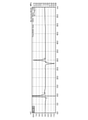
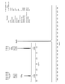
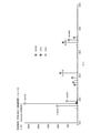
代表として、実施例9で得られた生成物をHPLC、NMR測定およびGC-MSにより同定した結果を図3~5に示す。図3は、実施例9で得られた生成物のHPLCチャートである。図4は、実施例9で得られた生成物のNMRチャートである。図5は、実施例9で得られた生成物のGC-MSチャートである。 As a representative, the results of identifying the product obtained in Example 9 by HPLC, NMR measurement and GC-MS are shown in FIGS. 3 to 5. FIG. 3 is an HPLC chart of the product obtained in Example 9. FIG. 4 is an NMR chart of the product obtained in Example 9. FIG. 5 is a GC-MS chart of the product obtained in Example 9.
図3に示すように、HPLCにおいて、エタノールのリテンションタイム(r.t.=30分)にピークが観測された。また、NMR測定において、エタノールのCH3、CH2に帰属するピークが観測された。また、GC-MSにおけるm/zがエタノールのフラグメントパターンと一致した。実施例9における生成物のエタノール選択率は、ほぼ100%であった。従来、エタノールは、水電解により生成した水素とCO2とを触媒反応させて合成していた。この方法では、エタノールの収率はあまり高くなかった。これに対し、金属イオンの還元体とCO2とを塩基性物質を含む溶液中で接触させることで、高い収率でエタノールを合成できることが確認された。 As shown in FIG. 3, a peak was observed in the retention time of ethanol (rt = 30 minutes) in HPLC. In addition, in NMR measurement, peaks attributable to CH 3 and CH 2 of ethanol were observed. In addition, m / z in GC-MS matched the fragment pattern of ethanol. The ethanol selectivity of the product in Example 9 was approximately 100%. Conventionally, ethanol has been synthesized by catalytically reacting hydrogen generated by water electrolysis with CO 2 . With this method, the yield of ethanol was not very high. On the other hand, it was confirmed that ethanol can be synthesized in high yield by contacting the reduced metal ion with CO 2 in a solution containing a basic substance.
(実施例16)
<硫酸鉄溶液の調製>
硫酸鉄(III)n水和物(試薬特級、和光純薬工業社製)にグルコン酸ナトリウム(試薬特級、和光純薬工業社製)を加え、イオン交換水で鉄イオン濃度が0.5Mとなるよう調製した。このとき、Fe3+に対してグルコン酸が等モル配位するよう調製した。
(Example 16)
<Preparation of iron sulfate solution>
Sodium gluconate (reagent special grade, manufactured by Wako Pure Chemical Industries, Ltd.) is added to iron (III) sulfate n hydrate (reagent special grade, manufactured by Wako Pure Chemical Industries, Ltd.), and the iron ion concentration is 0.5 M with ion-exchanged water. Prepared to be. At this time, it was prepared so that gluconic acid was coordinated equimolarly with Fe 3+ .
<金属イオンの還元体の作製>
以下の相違点を除いて、実施例1と同様に電解還元を行い、グルコン酸が配位した2価の鉄イオン錯体溶液を調製した。実施例1との相違点として、イオン交換水で2.5Mに調製した水酸化ナトリウム(試薬特級、和光純薬工業社製)の水溶液を用意し、80℃に加熱した。この水溶液に固体高分子電解質膜を1時間浸漬して、プロトンからNa+へカチオン交換した。また、電解セルの還元極側に硫酸鉄溶液を流通させ、酸化極側に1M水酸化ナトリウム水溶液を流通させた。
<Preparation of metal ion reducer>
Except for the following differences, electrolytic reduction was carried out in the same manner as in Example 1 to prepare a divalent iron ion complex solution coordinated with gluconic acid. As a difference from Example 1, an aqueous solution of sodium hydroxide (special grade reagent, manufactured by Wako Pure Chemical Industries, Ltd.) prepared to 2.5 M with ion-exchanged water was prepared and heated to 80 ° C. A solid polymer electrolyte membrane was immersed in this aqueous solution for 1 hour to exchange cations from protons to Na + . Further, an iron sulfate solution was circulated on the reducing electrode side of the electrolytic cell, and a 1M sodium hydroxide aqueous solution was circulated on the oxidizing electrode side.
<CO2の還元反応>
V2+溶液に代えてFe2+グルコン酸錯体溶液を用いた点を除いて、実施例1と同様にCO2の還元反応を進行させ、生成物の収率を算出した。結果を図6に示す。
<CO 2 reduction reaction>
The CO 2 reduction reaction was carried out in the same manner as in Example 1 except that Fe 2+ gluconic acid complex solution was used instead of V 2+ solution, and the yield of the product was calculated. The results are shown in FIG.
(実施例17)
Fe2+グルコン酸錯体溶液に金粉末(TAU-050、平均粒径0.5μm、アズワン0.1gを添加した点を除いて、実施例16と同様に金属イオンの還元体を作製し、CO2の還元反応を進行させ、生成物の収率を算出した。結果を図6に示す。
(Example 17)
A metal ion reduced product was prepared in the same manner as in Example 16 except that gold powder (TAU-050, average particle size 0.5 μm, and AS ONE 0.1 g) was added to the
(実施例18)
グルコン酸ナトリウムを添加せず、配位子を持たないFe2+溶液を調製した点を除いて、実施例16と同様に金属イオンの還元体を作製し、CO2の還元反応を進行させ、生成物の収率を算出した。結果を図6に示す。
(Example 18)
A metal ion reduced product was prepared in the same manner as in Example 16 except that a Fe 2+ solution having no ligand was prepared without adding sodium gluconate, and the CO 2 reduction reaction was allowed to proceed to generate it. The yield of the product was calculated. The results are shown in FIG.
(実施例19)
錯体を持たないFe2+溶液に金粉末(TAU-050、平均粒径0.5μm、アズワン社製)0.1gを添加した点を除いて、実施例18と同様に金属イオンの還元体を作製し、CO2の還元反応を進行させ、生成物の収率を算出した。結果を図6に示す。
(Example 19)
A metal ion reduced product was prepared in the same manner as in Example 18 except that 0.1 g of gold powder (TAU-050, average particle size 0.5 μm, manufactured by AS ONE) was added to a Fe 2+ solution having no complex. Then, the reduction reaction of CO 2 was allowed to proceed, and the yield of the product was calculated. The results are shown in FIG.
(実施例20)
<硫酸チタニル溶液の調製>
硫酸チタニル(IV)n水和物(キシダ化学社製)に硫酸(試薬特級、和光純薬工業社製)を加え、イオン交換水で硫酸イオン濃度が4Mとなるよう調製した。チタンイオン濃度は1Mとした。
(Example 20)
<Preparation of titanyl sulfate solution>
Sulfuric acid (special grade reagent, manufactured by Wako Pure Chemical Industries, Ltd.) was added to titanyl sulfate (IV) n hydrate (manufactured by Kishida Chemical Industries, Ltd.), and the sulfate ion concentration was adjusted to 4 M with ion-exchanged water. The titanium ion concentration was 1 M.
<金属イオンの還元体の作製>
電解セルの還元極側に硫酸チタニル溶液を流通させた点を除いて、実施例1と同様に電解還元を行い、3価のチタンイオン溶液を調製した。
<Preparation of metal ion reducer>
An electrolytic reduction was carried out in the same manner as in Example 1 except that the titanyl sulfate solution was circulated on the reducing electrode side of the electrolytic cell to prepare a trivalent titanium ion solution.
<CO2の還元反応>
V2+溶液に代えてTi3+溶液を用いた点を除いて、実施例1と同様にCO2の還元反応を進行させ、生成物の収率を算出した。結果を図6に示す。
<CO 2 reduction reaction>
The CO 2 reduction reaction was carried out in the same manner as in Example 1 except that the Ti 3+ solution was used instead of the V 2+ solution, and the yield of the product was calculated. The results are shown in FIG.
(実施例21)
Ti3+溶液に金粉末(TAU-050、平均粒径0.5μm、アズワン社製)0.1gを添加した点を除いて、実施例20と同様に金属イオンの還元体を作製し、CO2の還元反応を進行させ、生成物の収率を算出した。結果を図6に示す。
(Example 21)
A metal ion reduced product was prepared in the same manner as in Example 20 except that 0.1 g of gold powder (TAU-050, average particle size 0.5 μm, manufactured by AS ONE) was added to the Ti 3+ solution, and CO 2 was produced. The reduction reaction of was carried out, and the yield of the product was calculated. The results are shown in FIG.
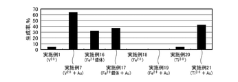
図6は、実施例16~21における有用物の生成率を示す図である。なお、図6では、参考として実施例1,7における有用物の生成率も図示している。図6に示すように、実施例1,16,20から、V2+だけでなくFe2+の錯体やTi3+でも、CO2から有用物を生成できることが確認された。また、実施例16,18から、Fe2+は錯体でなければ、還元反応を十分に進行させられないことが確認された。 FIG. 6 is a diagram showing the production rate of useful substances in Examples 16 to 21. Note that FIG. 6 also shows the production rate of useful substances in Examples 1 and 7 for reference. As shown in FIG. 6, from Examples 1, 16 and 20, it was confirmed that not only V 2+ but also Fe 2+ complex and Ti 3+ can produce useful substances from CO 2 . Further, from Examples 16 and 18, it was confirmed that the reduction reaction could not proceed sufficiently unless Fe 2+ was a complex.
これは、鉄イオンは2価/3価の標準電極電位が0.77V vs.SHE.と高く、したがってFe2+は還元力が小さいが、Fe2+の錯体ではグルコン酸等の配位により安定化し、これにより標準電極電位が下がって還元力が大きくなったためである。つまり、これらの実施例から、金属イオンの標準電極電位がCO2の還元反応における標準電極電位よりも低ければ、金属イオン種によらずCO2の還元反応を進行させられることが確認された。本発明者らは、2価のバナジウムイオンの錯体および3価のチタンイオンの錯体についても、有用物を生成できることを確認している。 This is because iron ions have a divalent / trivalent standard electrode potential of 0.77 V vs. SHE. Therefore, Fe 2+ has a small reducing power, but the Fe 2+ complex is stabilized by the coordination of gluconic acid and the like, which lowers the standard electrode potential and increases the reducing power. That is, from these examples, it was confirmed that if the standard electrode potential of the metal ion is lower than the standard electrode potential in the CO 2 reduction reaction, the CO 2 reduction reaction can proceed regardless of the metal ion species. The present inventors have confirmed that useful substances can also be produced for a complex of divalent vanadium ion and a complex of trivalent titanium ion.
また、実施例7,17,21から、Fe2+の錯体やTi3+の場合でも、導電性を有するAuを反応溶液に添加することでV2+の場合と同様の効果が得られることが確認された。つまり、金属イオン種によらず、導電性物質の添加によりCO2の還元反応を促進できることが確認された。 Further, from Examples 7, 17 and 21, it was confirmed that even in the case of Fe 2+ complex or Ti 3+ , the same effect as in the case of V 2+ can be obtained by adding the conductive Au to the reaction solution. rice field. That is, it was confirmed that the reduction reaction of CO 2 can be promoted by adding a conductive substance regardless of the metal ion species.
本発明は、上述の実施の形態に限定されるものではなく、当業者の知識に基づいて各種の設計変更等の変形を加えることも可能であり、そのような変形が加えられた実施の形態も本発明の範囲に含まれうるものである。 The present invention is not limited to the above-described embodiment, and various modifications such as design changes can be added based on the knowledge of those skilled in the art, and the embodiment to which such modifications are added. Can also be included in the scope of the present invention.
実施の形態で説明した構成要素の任意の組合せ、本発明の表現を方法、装置、システム等の間で変換したものもまた、本発明の態様として有効である。 Arbitrary combinations of components described in the embodiments, conversions of the representations of the invention between methods, devices, systems, etc. are also valid embodiments of the invention.
1 CO2還元装置、 2 固体高分子形電解ユニット、 4 CO2供給部、 6 反応部、 8 電源、 10 電気化学セル、 12 電解質膜、 14 還元極、 16 酸化極。 1 CO 2 reduction device, 2 solid polymer electrolyte unit, 4 CO 2 supply unit, 6 reaction unit, 8 power supply, 10 electrochemical cell, 12 electrolyte membrane, 14 reduction electrode, 16 oxidation electrode.
Claims (8)
前記還元体とCO2とを接触させ、前記還元体の酸化により前記CO2を還元することを含み、
前記金属イオンの標準電極電位(vs.SHE.)は、CO 2 の還元反応における標準電極電位(vs.SHE.)よりも低い、
CO2の還元方法。 The metal ion reducer is produced from the metal ion oxide by an electrochemical reduction reaction.
The present invention comprises contacting the reducing body with CO 2 and reducing the CO 2 by oxidizing the reducing body .
The standard electrode potential (vs. SHE.) Of the metal ion is lower than the standard electrode potential (vs. SHE.) In the reduction reaction of CO 2 .
CO 2 reduction method.
前記反応部に前記CO2を供給するCO2供給部と、
前記金属イオンの酸化体から電気化学還元反応により前記還元体を生成する固体高分子形電解ユニットと、を備え、
前記金属イオンの標準電極電位(vs.SHE.)は、CO 2 の還元反応における標準電極電位(vs.SHE.)よりも低い、
CO2還元装置。 A reaction unit that brings CO 2 into contact with a metal ion reducer and reduces the CO 2 by oxidizing the reducer.
A CO 2 supply unit that supplies the CO 2 to the reaction unit,
A solid polymer electrolyte electrolysis unit that produces the reduced product by an electrochemical reduction reaction from the oxidized body of the metal ion is provided .
The standard electrode potential (vs. SHE.) Of the metal ion is lower than the standard electrode potential (vs. SHE.) In the reduction reaction of CO 2 .
CO 2 reduction device.
Priority Applications (1)
| Application Number | Priority Date | Filing Date | Title |
|---|---|---|---|
| JP2018036732A JP6991893B2 (en) | 2018-03-01 | 2018-03-01 | Carbon dioxide reduction method and carbon dioxide reduction device |
Applications Claiming Priority (1)
| Application Number | Priority Date | Filing Date | Title |
|---|---|---|---|
| JP2018036732A JP6991893B2 (en) | 2018-03-01 | 2018-03-01 | Carbon dioxide reduction method and carbon dioxide reduction device |
Publications (2)
| Publication Number | Publication Date |
|---|---|
| JP2019151877A JP2019151877A (en) | 2019-09-12 |
| JP6991893B2 true JP6991893B2 (en) | 2022-02-03 |
Family
ID=67948367
Family Applications (1)
| Application Number | Title | Priority Date | Filing Date |
|---|---|---|---|
| JP2018036732A Active JP6991893B2 (en) | 2018-03-01 | 2018-03-01 | Carbon dioxide reduction method and carbon dioxide reduction device |
Country Status (1)
| Country | Link |
|---|---|
| JP (1) | JP6991893B2 (en) |
Families Citing this family (1)
| Publication number | Priority date | Publication date | Assignee | Title |
|---|---|---|---|---|
| JP7788153B2 (en) * | 2020-08-06 | 2025-12-18 | 国立研究開発法人産業技術総合研究所 | Method for producing hydrocarbon compounds from carbon dioxide at concentrations including low concentrations |
Citations (2)
| Publication number | Priority date | Publication date | Assignee | Title |
|---|---|---|---|---|
| JP2010099626A (en) | 2008-10-27 | 2010-05-06 | Mitsui Eng & Shipbuild Co Ltd | Apparatus and method for reducing and fixing carbon dioxide |
| JP2015172224A (en) | 2014-03-11 | 2015-10-01 | 株式会社東芝 | Photochemical reaction apparatus |
Family Cites Families (1)
| Publication number | Priority date | Publication date | Assignee | Title |
|---|---|---|---|---|
| JP3198298B2 (en) * | 1997-11-27 | 2001-08-13 | 経済産業省産業技術総合研究所長 | Method for producing hydrogen by photocatalyst-electrolysis hybrid system |
-
2018
- 2018-03-01 JP JP2018036732A patent/JP6991893B2/en active Active
Patent Citations (2)
| Publication number | Priority date | Publication date | Assignee | Title |
|---|---|---|---|---|
| JP2010099626A (en) | 2008-10-27 | 2010-05-06 | Mitsui Eng & Shipbuild Co Ltd | Apparatus and method for reducing and fixing carbon dioxide |
| JP2015172224A (en) | 2014-03-11 | 2015-10-01 | 株式会社東芝 | Photochemical reaction apparatus |
Also Published As
| Publication number | Publication date |
|---|---|
| JP2019151877A (en) | 2019-09-12 |
Similar Documents
| Publication | Publication Date | Title |
|---|---|---|
| Al‐Tamreh et al. | Electroreduction of carbon dioxide into formate: a comprehensive review | |
| Zhang et al. | Decoupled redox catalytic hydrogen production with a robust electrolyte-borne electron and proton carrier | |
| Frisch et al. | Seawater electrolysis using all-PGM-free catalysts and cell components in an asymmetric feed | |
| Wang et al. | Efficient solar-driven electrocatalytic CO2 reduction in a redox-medium-assisted system | |
| Kong et al. | Electrochemical synthesis of NH3 at low temperature and atmospheric pressure using a γ-Fe2O3 catalyst | |
| Lee et al. | Catholyte-free electroreduction of CO 2 for sustainable production of CO: concept, process development, techno-economic analysis, and CO 2 reduction assessment | |
| Weekes et al. | Electrolytic CO2 reduction in a flow cell | |
| Bevilacqua et al. | Recent technological progress in CO2 electroreduction to fuels and energy carriers in aqueous environments | |
| He et al. | Advances in electrolyzer design and development for electrochemical CO2 reduction | |
| US9217202B2 (en) | Membrane reactor | |
| Sapountzi et al. | Hydrogen from electrochemical reforming of C1–C3 alcohols using proton conducting membranes | |
| Ruiz-Lopez et al. | Electrochemical reforming of ethanol in a membrane-less reactor configuration | |
| US9145614B2 (en) | Membrane reactor | |
| Yang et al. | Photo-and thermo-coupled electrocatalysis in carbon dioxide and methane conversion | |
| KR101451630B1 (en) | Method for reducing carbon dioxide and reductor of carbon dioxide using the same | |
| Sanlı | A possible future fuel cell: the peroxide/peroxide fuel cell | |
| Fukushima et al. | Carbon-neutral energy cycles using alcohols | |
| KR20190083546A (en) | Electrochemical hydrogenation reactor and method of hydrogenation using the same | |
| Song et al. | Efficient solar-driven water splitting performance of S-doped NiFe-LDH based electrolyzer directly coupled with Si photovoltaic cell | |
| Tan et al. | Surface modification strategies for copper-based catalysts in selective CO2 electroreduction to multicarbon products | |
| JP6991893B2 (en) | Carbon dioxide reduction method and carbon dioxide reduction device | |
| Mehrabi et al. | Modular Solar-to-Fuel Electrolysis at Low Cell Potentials Enabled by Glycerol Electrooxidation and a Bipolar Membrane Separator | |
| Thijs et al. | Demonstration of a three compartment solar electrolyser with gas phase cathode producing formic acid from CO2 and water using Earth abundant metals | |
| CN113416972A (en) | Device and method for producing hydrogen by electrolyzing water step by step based on all-vanadium liquid flow redox medium | |
| CN103904337B (en) | The preparation method of paper-graphite-CoPd membrane electrode |
Legal Events
| Date | Code | Title | Description |
|---|---|---|---|
| A621 | Written request for application examination |
Free format text: JAPANESE INTERMEDIATE CODE: A621 Effective date: 20201016 |
|
| A977 | Report on retrieval |
Free format text: JAPANESE INTERMEDIATE CODE: A971007 Effective date: 20210811 |
|
| A131 | Notification of reasons for refusal |
Free format text: JAPANESE INTERMEDIATE CODE: A131 Effective date: 20210824 |
|
| A521 | Request for written amendment filed |
Free format text: JAPANESE INTERMEDIATE CODE: A523 Effective date: 20210928 |
|
| TRDD | Decision of grant or rejection written | ||
| A01 | Written decision to grant a patent or to grant a registration (utility model) |
Free format text: JAPANESE INTERMEDIATE CODE: A01 Effective date: 20211124 |
|
| A61 | First payment of annual fees (during grant procedure) |
Free format text: JAPANESE INTERMEDIATE CODE: A61 Effective date: 20211208 |
|
| R150 | Certificate of patent or registration of utility model |
Ref document number: 6991893 Country of ref document: JP Free format text: JAPANESE INTERMEDIATE CODE: R150 |
|
| R250 | Receipt of annual fees |
Free format text: JAPANESE INTERMEDIATE CODE: R250 |
|
| R250 | Receipt of annual fees |
Free format text: JAPANESE INTERMEDIATE CODE: R250 |