JP6991881B2 - Gas meter - Google Patents
Gas meter Download PDFInfo
- Publication number
- JP6991881B2 JP6991881B2 JP2018025733A JP2018025733A JP6991881B2 JP 6991881 B2 JP6991881 B2 JP 6991881B2 JP 2018025733 A JP2018025733 A JP 2018025733A JP 2018025733 A JP2018025733 A JP 2018025733A JP 6991881 B2 JP6991881 B2 JP 6991881B2
- Authority
- JP
- Japan
- Prior art keywords
- groove
- gas meter
- inclined guide
- room
- gas
- Prior art date
- Legal status (The legal status is an assumption and is not a legal conclusion. Google has not performed a legal analysis and makes no representation as to the accuracy of the status listed.)
- Active
Links
- 238000009423 ventilation Methods 0.000 claims description 17
- 238000005192 partition Methods 0.000 claims description 9
- 238000004891 communication Methods 0.000 claims description 8
- 230000005856 abnormality Effects 0.000 claims description 6
- 238000007599 discharging Methods 0.000 claims description 3
- 239000007789 gas Substances 0.000 description 48
- 210000003254 palate Anatomy 0.000 description 6
- XLYOFNOQVPJJNP-UHFFFAOYSA-N water Substances O XLYOFNOQVPJJNP-UHFFFAOYSA-N 0.000 description 5
- 230000008595 infiltration Effects 0.000 description 4
- 238000001764 infiltration Methods 0.000 description 4
- 238000013459 approach Methods 0.000 description 3
- 230000005540 biological transmission Effects 0.000 description 3
- 230000000903 blocking effect Effects 0.000 description 3
- 239000002737 fuel gas Substances 0.000 description 3
- 230000000994 depressogenic effect Effects 0.000 description 2
- 238000001514 detection method Methods 0.000 description 2
- 239000012530 fluid Substances 0.000 description 2
- 238000003780 insertion Methods 0.000 description 2
- 230000037431 insertion Effects 0.000 description 2
- AZDRQVAHHNSJOQ-UHFFFAOYSA-N alumane Chemical group [AlH3] AZDRQVAHHNSJOQ-UHFFFAOYSA-N 0.000 description 1
- 230000007423 decrease Effects 0.000 description 1
- 230000000694 effects Effects 0.000 description 1
- 238000012856 packing Methods 0.000 description 1
- 230000002093 peripheral effect Effects 0.000 description 1
- 239000011148 porous material Substances 0.000 description 1
- 238000007789 sealing Methods 0.000 description 1
- 238000000638 solvent extraction Methods 0.000 description 1
Images


Landscapes
- Measuring Volume Flow (AREA)
Description
本発明は、ガス圧異常を検出するための圧力センサを内蔵したガスメータに関する。 The present invention relates to a gas meter having a built-in pressure sensor for detecting a gas pressure abnormality.
この種のガスメータの圧力センサは、一般に、ガス圧と大気圧とを比較してガス圧の異常を検出する構造になっている。そして、従来のガスメータとして、圧力センサの収容部に大気圧を取り込むための通気孔を下面に備えたもの知られている(例えば、特許文献1参照)。 The pressure sensor of this type of gas meter is generally structured to detect an abnormality in gas pressure by comparing gas pressure with atmospheric pressure. Further, as a conventional gas meter, there is known that the accommodating portion of the pressure sensor is provided with a vent hole for taking in atmospheric pressure on the lower surface (see, for example, Patent Document 1).
しかしながら、上記した従来のガスメータでは、外側面を伝わる雨水が下面に回り込んで通気孔に入り込むことがある。 However, in the above-mentioned conventional gas meter, rainwater traveling on the outer surface may wrap around to the lower surface and enter the ventilation holes.
本発明は、上記事情に鑑みてなされたもので、通気孔への雨水の浸入を抑えることが可能なガスメータの提供を目的とする。 The present invention has been made in view of the above circumstances, and an object of the present invention is to provide a gas meter capable of suppressing the intrusion of rainwater into the ventilation holes.
上記目的を達成するためになされた請求項1の発明は、メータケース内を通過するガスの流量を計測すると共に、ガスの流路と隣り合わせの付属部屋に収容される圧力センサにより前記流路内のガス圧の異常を大気圧と比較して検出するガスメータにおいて、前記メータケースの下面に形成されて水平に延び、その端部が前記メータケースの外側面の下側位置で開口する溝端部開口となった下面溝と、前記下面溝内の天井面に開口し、前記付属部屋に大気圧を取り込む通気孔と、前記メータケースの外側面のうち前記溝端部開口からそれと略同じ幅で上方に延びる帯状領域の下端部に段付き状に形成され、前記帯状領域の幅方向に対して傾斜し、前記帯状領域を流下してくる雨水を受けて前記帯状領域の一側方へと案内する横傾斜案内面と、前記横傾斜案内面の下端部から上方に立ち上がり、前記横傾斜案内面に案内される雨水を堰き止める鉛直堰止面と、前記横傾斜案内面と前記鉛直堰止面との交差部分の一端に位置し、前記溝端部開口の一側縁部に上方から雨水を排出する雨水排出部と、を有するガスメータである。 The invention of claim 1 made to achieve the above object measures the flow rate of gas passing through the meter case, and also uses a pressure sensor housed in an accessory room adjacent to the gas flow path to enter the flow path. In a gas meter that detects abnormalities in gas pressure in comparison with atmospheric pressure, a groove end opening that is formed on the lower surface of the meter case and extends horizontally, and its end is opened at a lower position on the outer surface of the meter case. A lower surface groove that has become It is formed in a stepped shape at the lower end of the extending band-shaped area, is inclined with respect to the width direction of the band-shaped area, receives rainwater flowing down the band-shaped area, and guides it to one side of the band-shaped area. An inclined guide surface, a vertical blocking surface that rises upward from the lower end of the laterally inclined guide surface and blocks rainwater guided by the laterally inclined guide surface, and the laterally inclined guide surface and the vertical dam surface. It is a gas meter located at one end of the intersecting portion and having a rainwater discharging portion for discharging rainwater from above on one side edge portion of the groove end opening.
請求項2の発明は、前記帯状領域に陥没形成されて、その内側下部に前記横傾斜案内面を有すると共に、内側一側部に前記鉛直堰止面を有する凹部を備える請求項1に記載のガスメータである。 The first aspect of the present invention is the first aspect of the present invention, which is formed by being recessed in the band-shaped region, has the laterally inclined guide surface at the inner lower portion thereof, and has a recess having the vertical damming surface on one inner side portion thereof. It is a gas meter.
請求項3の発明は、前記メータケースの下面から突出するリブ形状をなし、その表裏の一方の面が、前記溝端部開口の前記一側縁部側の前記下面溝の一内側面を構成する下面リブを備える請求項1又は2に記載のガスメータである。 The invention of claim 3 has a rib shape protruding from the lower surface of the meter case, and one surface of the front and back thereof constitutes an inner surface of the lower surface groove on the one side edge side of the groove end opening. The gas meter according to claim 1 or 2, further comprising a lower surface rib.
請求項4の発明は、前記下面リブの前記表裏の他方の面は、前記横傾斜案内面の下端部より上側まで延長されている請求項3に記載のガスメータである。 The invention according to claim 4 is the gas meter according to claim 3, wherein the other surface of the front and back surfaces of the lower surface rib is extended from the lower end portion of the laterally inclined guide surface to the upper side.
請求項5の発明は、前記付属部屋には、前記圧力センサを収容する第1の付属部屋と、前記第1の付属部屋と区画壁を隔てて隣合わせに設けられて底部を前記通気孔が貫通する第2の付属部屋とが設けられ、前記第1と第2の付属部屋の間を連通する連通孔が、前記区画壁の上端部を貫通している請求項1乃至4の何れか1の請求項に記載のガスメータである。 According to the fifth aspect of the present invention, the accessory room is provided with a first accessory room for accommodating the pressure sensor and the first accessory room next to each other across a partition wall, and the ventilation hole penetrates the bottom portion. A second accessory room is provided, and a communication hole communicating between the first and second accessory rooms penetrates the upper end portion of the partition wall according to any one of claims 1 to 4. The gas meter according to the claim.
請求項6の発明は、前記第2の付属部屋は、水平方向に開口して、その開口部を塞ぐ蓋体を有し、前記下面溝は、前記第2の付属部屋の下側開口縁に沿って延び、前記蓋体の下端部から直角曲げされて、前記下面溝を下方から覆う溝カバーを備える請求項5に記載のガスメータである。 According to a sixth aspect of the present invention, the second ancillary chamber has a lid that opens horizontally to close the opening, and the lower surface groove is formed on the lower opening edge of the second ancillary chamber. The gas meter according to claim 5, further comprising a groove cover that extends along and is bent at a right angle from the lower end of the lid to cover the lower surface groove from below.
請求項1のガスメータでは、圧力センサに大気圧を取り込むための通気孔が、メータケースの下面に備えた下面溝の天井面に開口している。ここで、メータケースの外側面のうち下面溝の溝端部開口から上方に延びる帯状領域の下端部には、帯状領域の幅方向に傾斜する横傾斜案内面が段付き状に形成され、横傾斜案内面の下端部から鉛直堰止面が立ち上がっている。これにより、帯状領域を流下してくる雨水は、横傾斜案内面によって帯状領域の一側方へと案内されてから鉛直堰止面で堰き止められ、それら横傾斜案内面と鉛直堰止面との交差部分の一端の雨水排出部から溝端部開口の一側縁部へと排出され、さらに、その一側縁部の稜線伝いに流下して下面溝の下方に落ちる。つまり、横傾斜案内面を備えていないと、帯状領域を流下してくる雨水が下面溝の天井面に伝わり得るところを、本発明では、横傾斜案内面により雨水を溝端部開口の一側縁部に案内し、その一側縁部を雨樋として利用して下面溝の下方に導くことができる。これにより、下面溝の天井面に雨水が伝わることを規制することができ、通気孔への雨水の浸入が抑えられる。 In the gas meter of claim 1, a ventilation hole for taking in atmospheric pressure in the pressure sensor is opened on the ceiling surface of the lower surface groove provided on the lower surface of the meter case. Here, on the lower end of the strip-shaped region extending upward from the groove end opening of the lower surface groove on the outer surface of the meter case, a laterally inclined guide surface inclined in the width direction of the strip-shaped region is formed in a stepped manner and laterally inclined. A vertical weir stop surface rises from the lower end of the guide surface. As a result, the rainwater flowing down the belt-shaped region is guided to one side of the belt-shaped region by the laterally inclined guide surface, and then blocked by the vertical weir surface, and the laterally inclined guide surface and the vertical weir surface are used. It is discharged from the rainwater discharge portion at one end of the intersection to one side edge of the groove end opening, and further flows down along the ridgeline of the one side edge and falls below the lower surface groove. That is, in the present invention, the rainwater flowing down the strip-shaped region can be transmitted to the ceiling surface of the lower surface groove if the laterally inclined guide surface is not provided. It can be guided to the portion and the one side edge thereof can be used as a rain gutter to guide it below the lower surface groove. As a result, it is possible to regulate the transmission of rainwater to the ceiling surface of the lower surface groove, and the infiltration of rainwater into the ventilation holes is suppressed.
横傾斜案内面及び鉛直堰止面は、メータケースの外側面の突出部の上面又は側面として備えてもよいし、請求項2の構成のように、メータケースの外側面に陥没形成された凹部の内面として備えてもよい。請求項2の構成によれば、横傾斜案内面及び鉛直堰止面を備えるための突出部をメータケースの外側面へ設けずに済み、異物への引っ掛かりが防がれる。 The laterally inclined guide surface and the vertical damming surface may be provided as the upper surface or the side surface of the protrusion on the outer surface of the meter case, or a recess formed in the outer surface of the meter case as in the configuration of claim 2. It may be provided as the inner surface of the. According to the second aspect, it is not necessary to provide a protrusion for providing the laterally inclined guide surface and the vertical damming surface on the outer surface of the meter case, and the foreign matter can be prevented from being caught.
下面溝は、メータケースの下面に陥没した状態に形成されていてもよいが、請求項3のガスメータのように、メータケースの下面から突出する下面リブで下面溝の一内側面を構成し、前述の溝端部開口の一側縁部が下面リブの側縁部で構成されるようにすれば、下面リブの側縁部の表裏の2本の稜線を利用して、雨水を安定して鉛直下方に案内することができる。また、請求項4の発明のように、下面リブの表裏の他方の面を、横傾斜案内面の下端部より上側まで延長すれば、上記した2本の稜線のうちの1本を雨水排出部に近づけることができ、雨水排出部から溝端部開口の一側縁部への雨水の伝達が安定する。 The lower surface groove may be formed in a state of being depressed in the lower surface of the meter case, but as in the gas meter of claim 3, the lower surface rib protruding from the lower surface of the meter case constitutes one inner surface of the lower surface groove. If one side edge of the groove end opening is composed of the side edge of the lower surface rib, the two ridges on the front and back of the side edge of the lower surface rib can be used to stably verticalize rainwater. It can be guided downwards. Further, as in the invention of claim 4, if the other surface of the front and back surfaces of the lower surface rib is extended from the lower end portion of the laterally inclined guide surface to the upper side, one of the above two ridge lines can be used as the rainwater discharge portion. It is possible to approach to, and the transmission of rainwater from the rainwater discharge part to one side edge of the groove end opening is stable.
請求項5のガスメータでは、隣り合う第1と第2の付属部屋の間の区画壁の上部を連通孔が貫通し、第2の付属部屋の底部を通気孔が貫通しているので、仮に通気孔から第2の付属部屋に水が浸入したとしても、圧力センサを収容する第1の付属部屋にまで水が浸入することが防がれる。 In the gas meter of claim 5, the communication hole penetrates the upper part of the partition wall between the adjacent first and second accessory rooms, and the ventilation hole penetrates the bottom of the second accessory room. Even if water enters the second accessory room through the pores, it is possible to prevent water from entering the first accessory room that houses the pressure sensor.
請求項5のガスメータでは、第2の付属部屋の開口部を塞ぐ蓋体の下端部から直角曲げされた溝カバーにより下面溝が下方から覆われているので、この点においても通気孔への雨水の浸入が抑えられる。 In the gas meter of claim 5, the lower surface groove is covered from below by a groove cover bent at a right angle from the lower end of the lid that closes the opening of the second accessory room. Infiltration is suppressed.
以下、本発明の一実施形態を図1~図9に基づいて説明する。図1に示された本実施形態のガスメータ10は、ガスの配管99の途中に接続されるメータケース11に、遮断弁20(図2参照),計測管50(図3参照)、整流器70(図3参照)等を収容して備える。
Hereinafter, an embodiment of the present invention will be described with reference to FIGS. 1 to 9. The
メータケース11は、例えばアルミの鋳物部品であって、横方向に延びた略直方体状のダクト部12を有する。以下、ダクト部12が延びる第1の水平方向を「横方向H1」といい、それと直交する第2水平方向を「前後方向H2」という。また、前後方向H2のうち後述する前面フランジ16を有する側を「前側」等といい、その反対側を「後側」等ということとする。
The
図2に示すように、ダクト部12のうち前方から見て左側にはフード部13が備えられ、フード部13内が本発明に係る第2の付属部屋10Kになっている。また、フード部13の四隅には、面取り傾斜壁35が備えられている。さらに、フード部13の先端部からは四角形のフード部フランジ36が四方に張り出している。フード部フランジ36には、フード部13の開口より一回り大きな環状のOリング溝37が形成されると共に、Oリング溝37より外側の四隅に螺子孔が形成されている。そして、Oリング溝37にOリング(図示せず)が収容された状態で、板状の蓋体15がフード部フランジ36に宛がわれて螺子止めされている。これにより、第2の付属部屋10Kの開口部13Kが密閉されている。
As shown in FIG. 2, a
フード部13とダクト部12との間は、弁装着壁14によって区画されている。また、ダクト部12内は、弁装着壁14側から横方向H1に順番に並ぶ第1~第3の仕切壁25,26,27により、同じく順番に並ぶ、遮断部屋30、流入部屋31、中間部屋32及び流出部屋33に区画されている。
The
ダクト部12の上面の左右の両端部には、1対の配管接続部23,24が突設されて遮断部屋30と流出部屋33とに連通している。そして、遮断部屋30に連通する一方の配管接続部23に燃料ガスの供給元側の配管99(図2参照)が接続される一方、流出部屋33に連通する他方の配管接続部24に燃料ガスの使用者側の配管99が接続される。
A pair of
図3に示すように、弁装着壁14には円形の貫通孔14Aが形成され、その貫通孔14Aより一回り小さい円形の貫通孔25Aが第1仕切壁25に形成されている。そして、図2に示すように、遮断弁20のフランジ20Fがフード部13側の弁装着壁14の開口縁に宛われて螺子止めされ、遮断弁20の弁体21が遮断部屋30に収容されている。そして、図3に示すように、通常時には、弁体21が貫通孔25Aから離間し、燃料ガスの流量等に異常が生じた時には、弁体21が貫通孔25Aを閉塞する。
As shown in FIG. 3, a circular through
図4に示すように、メータケース11の前面には、前面フランジ16が備えられている。前面フランジ16は、外縁部が横長の長方形をなし、ダクト部12から上下に張り出し、横方向H1の一端部がフード部13と一体になっている。また、前面フランジ16の前面には、外縁部を除く全体を段付き状に陥没させて陥没部16Aが形成され、その陥没部16A内に、流入部屋31、中間部屋32及び流出部屋33の前面全体を開放する部品受容口17が形成されている。
As shown in FIG. 4, a
流入部屋31には、部品受容口17から前述の整流器70が収容されていて、ガスの流れの均一化が図られている。また、第2及び第3の仕切壁26,27には、部品受容口17側が開口した矩形切欠部29,29が備えられている。これに対し、計測管50が角筒状をなし、その両端寄り位置に嵌合された1対の枠形シール部材60,60が矩形切欠部29,29に嵌合されて、計測管50が流入部屋31と流出部屋33との間を連絡している。また、計測管50には、図示しない1対の超音波素子が内蔵され、一方の超音波素子から送波された超音波が流体を伝播して他方の超音波素子に受波される伝搬時間に基づいて、後述する回路基板98(図2参照)上の制御回路がガスの使用量を演算する。
The above-mentioned
図2に示すように、受容口蓋18は、部品受容口17より一回り大きな長方形の板状をなし、外周部をメータケース11に螺子止めされる。また、受容口蓋18の内面には、図示しないパッキンが敷設され、流入部屋31と中間部屋32との間、中間部屋32と流出部屋33との間が気密状態に区画されている。
As shown in FIG. 2, the receiving
受容口蓋18のうち中間部屋32に対向する部分には、ケーブル挿通孔18Aが形成され、計測管50の超音波素子の図示しないケーブルがケーブル挿通孔18Aを通して受容口蓋18の前側に引き出されている。
A
図4に示すように、陥没部16A内の左辺上部には、フード部13内に連通する連通孔77が備えられ、その連通孔77を通して遮断弁20の図示しないケーブルが陥没部16Aの前側に引き出されている。
As shown in FIG. 4, a
陥没部16A内の左辺中間部には、遮断部屋30に連通する内圧検出孔78が形成され、その内圧検出孔78を塞ぐように図2に示した圧力センサ80が取り付けられている。圧力センサ80は、遮断部屋30内のガス圧と大気圧とを表裏の一方と他方とに受ける図示しないダイヤフラムを内蔵している。
An internal
陥没部16Aには、受容口蓋18の前側に回路基板98が重ねて取り付けられている。そして、前面フランジ16の全体を覆うように箱形の前面カバー81が取り付けられて、その前面カバー81の内に本発明に係る第1の付属部屋10Jが形成されている。
A
回路基板98には、超音波素子、遮断弁20,圧力センサ80が接続されると共に、第1の付属部屋10J内に収容された図示しない電池が電源として回路基板98に接続されている。そして、回路基板98に実装された制御回路により、前述の如く超音波素子を利用して流体の流量が計測される。
An ultrasonic element, a
また、回路基板98のスイッチを介して遮断弁20が給電されていて通常は弁体21が貫通孔25Aから離間されている。そして、圧力センサ80にてガス圧の異常が検出されると遮断弁20への通電が遮断され、弁体21が貫通孔25Aを閉塞する。また、回路基板98には、震動検出器も実装されていて、その震動検出器が基準値以上の揺れを検出したときにも遮断弁20への通電が遮断されて貫通孔25Aが閉塞される。
Further, the
図5には、メータケース11の下面及び後面の形状が示されている。ダクト部12の下面には、横方向H1の両端部から1対の下面リブ61,62が垂下されている。それら下面リブ61,62は、ダクト部12の下面における前後方向H2の全体に亘って延び、前端部は前面フランジ16に接続されている。また、下面リブ61,62の下面は、前面フランジ16の下面と面一に配置され、それら下面リブ62等の下面よりフード部フランジ36の下面は僅かに上方に位置している。さらに、一方の下面リブ62は、ダクト部12とフード部13との間の弁装着壁14の真下に位置している。そして、その下面リブ62とフード部フランジ36との間が、本発明に係る下面溝64になっている。
FIG. 5 shows the shapes of the lower surface and the rear surface of the
図6に示すように、下面溝64の天井面64Aには、1対の通気孔13B,13Bが並べて形成されている。そして、図1に示すように、これら通気孔13B,13Bと、フード部13内の第2の付属部屋10Kと前述の連通孔77とを通して、圧力センサ80を収容する第1の付属部屋10Jに大気圧が取り込まれる。
As shown in FIG. 6, a pair of
図6に示すように、下面溝64の前端は、前面フランジ16によって閉塞される一方、下面溝64の後端は、本発明に係る溝端部開口65として後方に向かって開口している。また、下面溝64の下面開口は、蓋体15の下端部から直角曲げされた溝カバー15Aによって覆われている。図7に示すように、溝カバー15Aは、前後方向H2に延びる帯板状をなし、下面溝64のうち下面リブ62によって形成される一方の溝内側面62Bの下端寄り位置に突き合わされている。また、溝カバー15Aの横幅は、前方に向かうに従って徐々に小さくなっていて、溝カバー15Aの先端と溝内側面62Bとの間の隙間は前方に向かうに従って徐々に大きくなっている。さらには、溝カバー15Aの全長は、下面リブ62の前後方向H2の全長より僅かに短くなっていて、前面フランジ16と溝カバー15Aの前端部との間には、僅かに隙間が形成されている。また、溝カバー15Aは、前方に向かうに従って徐々に下るように僅かに傾斜している。
As shown in FIG. 6, the front end of the
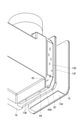
フード部フランジ36は、下面リブ62より後方に大きく突出している。また、フード部13の後部下端の面取り傾斜壁35の外面は、その下部が、下面リブ62の後端より前側に位置する一方、面取り傾斜壁35の上部が、下面リブ62の後端より後方に位置している。そして、面取り傾斜壁35の外面下端に段差壁部82が形成されている。
The
段差壁部82の下面は、下面溝64の天井面64Aの一部(後端部)を構成している。また、段差壁部82の後面と下面リブ62の後面とダクト部12全体の後面と面一になって連続しかつ前後方向H2に対して直交した鉛直外面83になっている。そして、フード部13の後部下端の面取り傾斜壁35の外面の上端部が、鉛直外面83より後方に位置して、その上方にフード部13の後面13D(以下、「フード後面13D」という)が帯状をなして上下方向に延び、さらに、そのフード後面13Dの上端に、フード部13の後部上端の面取り傾斜壁35の外面が続いている。そして、フード後面13Dの一側縁部に、鉛直外面83との間の段差面13Eが形成されている。
The lower surface of the
段差壁部82とフード後面13Dとの間は、本発明に係る凹部84になっている。そして、凹部84内に位置する段差壁部82の上面が、本発明に係る横傾斜案内面90をなし、下面リブ62によって形成される凹部84内の一側面が、本発明に係る鉛直堰止面91をなしている。
A
図9に示すように、横傾斜案内面90は、前後方向H2に対して平行で、横方向H1に対しては、下面リブ62に接近するに従って下るように傾斜している。また、横方向H1に対する横傾斜案内面90の傾斜角は、例えば5~30度になっている。一方、鉛直堰止面91は、下面溝64の一方の溝内側面62Bと面一になっている。そして、横傾斜案内面90と縦傾斜面92とが交差する交差部分のうち鉛直外面83側の一端が、本発明に係る雨水排出部93になっている。そして、下面溝64の溝内側面62Bと鉛直外面83とが交差してなる稜線R1が、雨水排出部93の真下位置で上下方向に延びている。また、下面リブ62のうち下面溝64の溝内側面62Bとは反対側の外側面62Aと鉛直外面83との稜線R2は、雨水排出部93の上方位置から下面リブ62の下端部まで延びている。なお、横傾斜案内面90の上隣の面取り傾斜壁35の外面は、以下、「縦傾斜面92」ということとする。
As shown in FIG. 9, the laterally
本実施形態のガスメータ10の構成に関する説明は以上である。次に本実施形態のガスメータ10の作用効果について説明する。本実施形態のガスメータ10は屋外の雨水がかかる場所に設置されることがある。また、ガスメータ10は、図6に示すように、通気孔13B,13Bを備えているが、それら通気孔13B,13Bは、メータケース11の下面溝64の天井面64Aに開口しているので、通常であれば、通気孔13B,13Bに雨水が入り込むことはない。しかしながら、例えば晴天から急転して雨天になると、ガスメータ10が冷却されてメータケース11内に負圧状態になり、このとき下面溝64の天井面64Aに雨水が伝わっていると、通気孔13B,13Bからメータケース11内に雨水が入り込む事態が生じう得る。
This concludes the description of the configuration of the
これに対し、本実施形態のガスメータ10では、メータケース11のうち下面溝64の溝端部開口65から略同じ横幅で上方に延びる帯状領域の下端部に、横方向H1に対して傾斜する横傾斜案内面90が段付き状に形成されて、その横傾斜案内面90の下端部から鉛直堰止面91が立ち上がっている。これにより、図8に示すように、帯状領域内(具体的には、フード後面13D、縦傾斜面92)を流下してくる雨水が、横傾斜案内面90によって帯状領域の一側方へと案内されてから鉛直堰止面91で堰き止められ、それら横傾斜案内面90と鉛直堰止面91との交差部分の一端の雨水排出部93から溝端部開口65の一側縁部へと排出されて、その一側縁部の稜線R1,R2伝いに雨水が流下して下面溝64の下方に落ちる。
On the other hand, in the
つまり、図9に示すように、横傾斜案内面90を備えていないと、帯状領域内のフード後面13D、縦傾斜面92を流下してくる雨水が下面溝64の天井面64Aに伝わり得るところを、本実施形態のガスメータ10では、図8に示すように、横傾斜案内面90を備えたことで雨水を溝端部開口65の一側縁部に案内して、その一側縁部を雨樋として利用して下面溝64の下方に導くことができる。これにより、下面溝64の天井面64Aに雨水が伝わることが規制され、通気孔13B,13Bへの雨水の浸入が抑えられる。
That is, as shown in FIG. 9, if the laterally
また、横傾斜案内面90及び鉛直堰止面91は、メータケース11の後面から突出する突出部の上面又は側面として備えてもよいが、本実施形態のように凹部84の内面として備えれば、突出部による異物への引っ掛かりを防ぐことができる。
Further, the laterally
下面溝64は、メータケース11の下面に陥没した状態に形成されていてもよいが、本実施形態では、メータケース11の下面から突出する下面リブ62で下面溝64の一方の溝内側面62Bを構成し、前述の溝端部開口65の一側縁部が下面リブ62の側縁部で構成されているので、下面リブ62の側縁部の表裏の2本の稜線R1,R2を利用して、雨水を安定して鉛直下方に案内することができる。しかも、それら一方の稜線R2は、雨水排出部93より上方まで延びてその途中部分が雨水排出部93に接近しているので、その稜線R2を伝わって雨水排出部93から溝端部開口65の一側縁部へと雨水が安定して伝わる。
The
また、本実施形態では、第1と第2の付属部屋10J,10Kの間を区画する壁部の上部を連通孔77が貫通し、第2の付属部屋10Kの底部を通気孔13B,13Bが貫通しているので、仮に通気孔13B,13Bから第2の付属部屋10Kに水が浸入したとしても、圧力センサ80を収容する第1の付属部屋10Jにまで水が浸入することが防がれる。しかも、第2の付属部屋10Kの開口部13Kを塞ぐ蓋体15の下端部から直角曲げされた溝カバー15Aにより下面溝64が下方から覆われているので、この点においても通気孔13B,13Bへの雨水の浸入が抑えられる。仮に、溝カバー15Aの上に雨水が落ちても、溝カバー15Aは傾斜しているので、溝カバー15A上に雨水が溜まることはない。
Further, in the present embodiment, the
[他の実施形態]
本発明は、前記実施形態に限定されるものではなく、例えば、以下に説明するような実施形態も本発明の技術的範囲に含まれ、さらに、下記以外にも要旨を逸脱しない範囲内で種々変更して実施することができる。
[Other embodiments]
The present invention is not limited to the above-described embodiment, and for example, embodiments as described below are also included in the technical scope of the present invention, and various other than the following, as long as they do not deviate from the gist. It can be changed and implemented.
(1)前記実施形態のガスメータ10は、1対の超音波素子を利用してガスの流量を計測する構成になっていたが、本発明に係るガスメータの流量の計測原理はどのようなものであってもよい。
(1) The
(2)前記実施形態の横傾斜案内面90は、帯状領域の幅方向である横方向H1に傾斜し、前後方向H2に対しては平行になっていたが、前後方向H2に対して傾斜していてもよい。また、鉛直堰止面91も鉛直方向に対して傾斜していてもよい。
(2) The laterally
(3)前記実施形態の横傾斜案内面90は、メータケース11の後面に備えた凹部84の内部に配置されていたが、凹部を設けず、例えば、メータケース11の後面から突出する突部の上面と側面とに、横傾斜案内面90と鉛直堰止面91とを備えた構成としてもよい。
(3) The laterally
10 ガスメータ
10J 第1の付属部屋
10K 第2の付属部屋
11 メータケース
13B 通気孔
13K 開口部
15 蓋体
15A 溝カバー
61,62 下面リブ
62A 外側面(表裏の他方の面)
62B 溝内側面(表裏の一方の面)
64 下面溝
64A 天井面
65 溝端部開口
77 連通孔
80 圧力センサ
84 凹部
90 横傾斜案内面
91 鉛直堰止面
93 雨水排出部
10
62B Groove inner side surface (one side of front and back)
64
Claims (6)
前記メータケースの下面に形成されて水平に延び、その端部が前記メータケースの外側面の下側位置で開口する溝端部開口となった下面溝と、
前記下面溝内の天井面に開口し、前記付属部屋に大気圧を取り込む通気孔と、
前記メータケースの外側面のうち前記溝端部開口からそれと略同じ幅で上方に延びる帯状領域の下端部に段付き状に形成され、前記帯状領域の幅方向に対して傾斜し、前記帯状領域を流下してくる雨水を受けて前記帯状領域の一側方へと案内する横傾斜案内面と、
前記横傾斜案内面の下端部から上方に立ち上がり、前記横傾斜案内面に案内される雨水を堰き止める鉛直堰止面と、
前記横傾斜案内面と前記鉛直堰止面との交差部分の一端に位置し、前記溝端部開口の一側縁部に上方から雨水を排出する雨水排出部と、を有するガスメータ。 In a gas meter that measures the flow rate of gas passing through the meter case and detects abnormalities in gas pressure in the flow path by comparing it with atmospheric pressure by a pressure sensor housed in an accessory room adjacent to the gas flow path. ,
A lower surface groove formed on the lower surface of the meter case, extending horizontally, and having a groove end opening whose end is an opening at a lower position on the outer surface of the meter case.
A ventilation hole that opens to the ceiling surface in the lower surface groove and takes in atmospheric pressure in the accessory room,
The outer surface of the meter case is formed in a stepped manner at the lower end of a band-shaped region extending upward from the groove end opening with substantially the same width as the groove end opening, and is inclined with respect to the width direction of the band-shaped region to form the band-shaped region. A laterally inclined guide surface that receives rainwater flowing down and guides it to one side of the band-shaped region,
A vertical dam surface that rises upward from the lower end of the laterally inclined guide surface and blocks rainwater guided by the laterally inclined guide surface.
A gas meter having a rainwater discharge portion located at one end of an intersection of the laterally inclined guide surface and the vertical weir stop surface and discharging rainwater from above on one side edge of the groove end opening.
前記下面溝は、前記第2の付属部屋の下側開口縁に沿って延び、
前記蓋体の下端部から直角曲げされて、前記下面溝を下方から覆う溝カバーを備える請求項5に記載のガスメータ。 The second accessory room has a lid that opens horizontally and closes the opening.
The bottom groove extends along the lower opening edge of the second accessory chamber.
The gas meter according to claim 5, further comprising a groove cover that is bent at a right angle from the lower end of the lid and covers the lower surface groove from below.
Priority Applications (1)
| Application Number | Priority Date | Filing Date | Title |
|---|---|---|---|
| JP2018025733A JP6991881B2 (en) | 2018-02-16 | 2018-02-16 | Gas meter |
Applications Claiming Priority (1)
| Application Number | Priority Date | Filing Date | Title |
|---|---|---|---|
| JP2018025733A JP6991881B2 (en) | 2018-02-16 | 2018-02-16 | Gas meter |
Publications (2)
| Publication Number | Publication Date |
|---|---|
| JP2019144001A JP2019144001A (en) | 2019-08-29 |
| JP6991881B2 true JP6991881B2 (en) | 2022-01-13 |
Family
ID=67772160
Family Applications (1)
| Application Number | Title | Priority Date | Filing Date |
|---|---|---|---|
| JP2018025733A Active JP6991881B2 (en) | 2018-02-16 | 2018-02-16 | Gas meter |
Country Status (1)
| Country | Link |
|---|---|
| JP (1) | JP6991881B2 (en) |
Families Citing this family (1)
| Publication number | Priority date | Publication date | Assignee | Title |
|---|---|---|---|---|
| CN120427071B (en) * | 2025-07-07 | 2025-09-09 | 浙江蓝宝石仪表科技有限公司 | A highly sealed intelligent gas meter |
Citations (1)
| Publication number | Priority date | Publication date | Assignee | Title |
|---|---|---|---|---|
| CN111811603A (en) | 2020-07-20 | 2020-10-23 | 安徽翼迈科技股份有限公司 | A waterproof structure of a passive photoelectric direct reading watch case |
Family Cites Families (4)
| Publication number | Priority date | Publication date | Assignee | Title |
|---|---|---|---|---|
| JPH0219699Y2 (en) * | 1985-12-23 | 1990-05-30 | ||
| JPH0534525U (en) * | 1991-10-14 | 1993-05-07 | 愛知時計電機株式会社 | Gas meter storage structure |
| JP3662343B2 (en) * | 1996-05-22 | 2005-06-22 | 東洋計器株式会社 | Gas meter with built-in pressure sensor |
| JP2011085541A (en) * | 2009-10-19 | 2011-04-28 | Sharp Corp | Drainage structure of terminal device installed outdoors |
-
2018
- 2018-02-16 JP JP2018025733A patent/JP6991881B2/en active Active
Patent Citations (1)
| Publication number | Priority date | Publication date | Assignee | Title |
|---|---|---|---|---|
| CN111811603A (en) | 2020-07-20 | 2020-10-23 | 安徽翼迈科技股份有限公司 | A waterproof structure of a passive photoelectric direct reading watch case |
Also Published As
| Publication number | Publication date |
|---|---|
| JP2019144001A (en) | 2019-08-29 |
Similar Documents
| Publication | Publication Date | Title |
|---|---|---|
| JP6194852B2 (en) | Air flow measurement device with humidity detection function | |
| JP6991881B2 (en) | Gas meter | |
| JP7033948B2 (en) | Ultrasonic flow meter | |
| JP5779471B2 (en) | Humidity detector | |
| JP7688519B2 (en) | Gas meter | |
| CN109789366B (en) | Dust-proof and splash-proof filter | |
| JP5844661B2 (en) | Gas-liquid separator | |
| JP2010243421A (en) | Ultrasonic gas meter | |
| US10508827B2 (en) | Ventilating device | |
| CN101418965B (en) | Indoor unit of cir conditioner | |
| RU147635U1 (en) | PIPE VALVE | |
| JP4728071B2 (en) | Gas detector | |
| US10551402B2 (en) | Air sensor system | |
| JP4583831B2 (en) | Gas meter | |
| CN202091216U (en) | Ventilating fan | |
| CN205213200U (en) | Casing and instrument with vent | |
| JP2005221359A (en) | Gas meter | |
| JP5959498B2 (en) | Humidifier and air conditioner | |
| JP6813985B2 (en) | Gas meter | |
| JP6085124B2 (en) | Gas meter drainage structure and gas meter | |
| JP6991882B2 (en) | Ultrasonic flow meter | |
| CA2704513C (en) | Instrument housing | |
| JP6478258B1 (en) | Gas meter | |
| JP5030099B2 (en) | Gas meter | |
| JP2017090361A (en) | Ultrasonic flow meter |
Legal Events
| Date | Code | Title | Description |
|---|---|---|---|
| RD04 | Notification of resignation of power of attorney |
Free format text: JAPANESE INTERMEDIATE CODE: A7424 Effective date: 20190315 |
|
| A621 | Written request for application examination |
Free format text: JAPANESE INTERMEDIATE CODE: A621 Effective date: 20210106 |
|
| A977 | Report on retrieval |
Free format text: JAPANESE INTERMEDIATE CODE: A971007 Effective date: 20211115 |
|
| TRDD | Decision of grant or rejection written | ||
| A01 | Written decision to grant a patent or to grant a registration (utility model) |
Free format text: JAPANESE INTERMEDIATE CODE: A01 Effective date: 20211130 |
|
| A61 | First payment of annual fees (during grant procedure) |
Free format text: JAPANESE INTERMEDIATE CODE: A61 Effective date: 20211208 |
|
| R150 | Certificate of patent or registration of utility model |
Ref document number: 6991881 Country of ref document: JP Free format text: JAPANESE INTERMEDIATE CODE: R150 |
|
| R250 | Receipt of annual fees |
Free format text: JAPANESE INTERMEDIATE CODE: R250 |