JP6991864B2 - Liquid discharge device - Google Patents
Liquid discharge device Download PDFInfo
- Publication number
- JP6991864B2 JP6991864B2 JP2018002017A JP2018002017A JP6991864B2 JP 6991864 B2 JP6991864 B2 JP 6991864B2 JP 2018002017 A JP2018002017 A JP 2018002017A JP 2018002017 A JP2018002017 A JP 2018002017A JP 6991864 B2 JP6991864 B2 JP 6991864B2
- Authority
- JP
- Japan
- Prior art keywords
- liquid
- adjusting
- ink
- discharge device
- impedance
- Prior art date
- Legal status (The legal status is an assumption and is not a legal conclusion. Google has not performed a legal analysis and makes no representation as to the accuracy of the status listed.)
- Active
Links
Images

Classifications
-
- B—PERFORMING OPERATIONS; TRANSPORTING
- B41—PRINTING; LINING MACHINES; TYPEWRITERS; STAMPS
- B41J—TYPEWRITERS; SELECTIVE PRINTING MECHANISMS, i.e. MECHANISMS PRINTING OTHERWISE THAN FROM A FORME; CORRECTION OF TYPOGRAPHICAL ERRORS
- B41J2/00—Typewriters or selective printing mechanisms characterised by the printing or marking process for which they are designed
- B41J2/005—Typewriters or selective printing mechanisms characterised by the printing or marking process for which they are designed characterised by bringing liquid or particles selectively into contact with a printing material
- B41J2/01—Ink jet
- B41J2/07—Ink jet characterised by jet control
-
- B—PERFORMING OPERATIONS; TRANSPORTING
- B41—PRINTING; LINING MACHINES; TYPEWRITERS; STAMPS
- B41J—TYPEWRITERS; SELECTIVE PRINTING MECHANISMS, i.e. MECHANISMS PRINTING OTHERWISE THAN FROM A FORME; CORRECTION OF TYPOGRAPHICAL ERRORS
- B41J2/00—Typewriters or selective printing mechanisms characterised by the printing or marking process for which they are designed
- B41J2/005—Typewriters or selective printing mechanisms characterised by the printing or marking process for which they are designed characterised by bringing liquid or particles selectively into contact with a printing material
- B41J2/01—Ink jet
- B41J2/135—Nozzles
- B41J2/14—Structure thereof only for on-demand ink jet heads
-
- B—PERFORMING OPERATIONS; TRANSPORTING
- B41—PRINTING; LINING MACHINES; TYPEWRITERS; STAMPS
- B41J—TYPEWRITERS; SELECTIVE PRINTING MECHANISMS, i.e. MECHANISMS PRINTING OTHERWISE THAN FROM A FORME; CORRECTION OF TYPOGRAPHICAL ERRORS
- B41J2/00—Typewriters or selective printing mechanisms characterised by the printing or marking process for which they are designed
- B41J2/005—Typewriters or selective printing mechanisms characterised by the printing or marking process for which they are designed characterised by bringing liquid or particles selectively into contact with a printing material
- B41J2/01—Ink jet
- B41J2/17—Ink jet characterised by ink handling
- B41J2/175—Ink supply systems ; Circuit parts therefor
- B41J2/17503—Ink cartridges
-
- B—PERFORMING OPERATIONS; TRANSPORTING
- B41—PRINTING; LINING MACHINES; TYPEWRITERS; STAMPS
- B41J—TYPEWRITERS; SELECTIVE PRINTING MECHANISMS, i.e. MECHANISMS PRINTING OTHERWISE THAN FROM A FORME; CORRECTION OF TYPOGRAPHICAL ERRORS
- B41J2/00—Typewriters or selective printing mechanisms characterised by the printing or marking process for which they are designed
- B41J2/005—Typewriters or selective printing mechanisms characterised by the printing or marking process for which they are designed characterised by bringing liquid or particles selectively into contact with a printing material
- B41J2/01—Ink jet
- B41J2/17—Ink jet characterised by ink handling
- B41J2/175—Ink supply systems ; Circuit parts therefor
- B41J2/17563—Ink filters
-
- B—PERFORMING OPERATIONS; TRANSPORTING
- B41—PRINTING; LINING MACHINES; TYPEWRITERS; STAMPS
- B41J—TYPEWRITERS; SELECTIVE PRINTING MECHANISMS, i.e. MECHANISMS PRINTING OTHERWISE THAN FROM A FORME; CORRECTION OF TYPOGRAPHICAL ERRORS
- B41J2/00—Typewriters or selective printing mechanisms characterised by the printing or marking process for which they are designed
- B41J2/005—Typewriters or selective printing mechanisms characterised by the printing or marking process for which they are designed characterised by bringing liquid or particles selectively into contact with a printing material
- B41J2/01—Ink jet
- B41J2/17—Ink jet characterised by ink handling
- B41J2/175—Ink supply systems ; Circuit parts therefor
- B41J2/17566—Ink level or ink residue control
-
- B—PERFORMING OPERATIONS; TRANSPORTING
- B41—PRINTING; LINING MACHINES; TYPEWRITERS; STAMPS
- B41J—TYPEWRITERS; SELECTIVE PRINTING MECHANISMS, i.e. MECHANISMS PRINTING OTHERWISE THAN FROM A FORME; CORRECTION OF TYPOGRAPHICAL ERRORS
- B41J2/00—Typewriters or selective printing mechanisms characterised by the printing or marking process for which they are designed
- B41J2/005—Typewriters or selective printing mechanisms characterised by the printing or marking process for which they are designed characterised by bringing liquid or particles selectively into contact with a printing material
- B41J2/01—Ink jet
- B41J2/17—Ink jet characterised by ink handling
- B41J2/18—Ink recirculation systems
-
- B—PERFORMING OPERATIONS; TRANSPORTING
- B41—PRINTING; LINING MACHINES; TYPEWRITERS; STAMPS
- B41J—TYPEWRITERS; SELECTIVE PRINTING MECHANISMS, i.e. MECHANISMS PRINTING OTHERWISE THAN FROM A FORME; CORRECTION OF TYPOGRAPHICAL ERRORS
- B41J2/00—Typewriters or selective printing mechanisms characterised by the printing or marking process for which they are designed
- B41J2/005—Typewriters or selective printing mechanisms characterised by the printing or marking process for which they are designed characterised by bringing liquid or particles selectively into contact with a printing material
- B41J2/01—Ink jet
- B41J2/17—Ink jet characterised by ink handling
- B41J2/19—Ink jet characterised by ink handling for removing air bubbles
-
- B—PERFORMING OPERATIONS; TRANSPORTING
- B41—PRINTING; LINING MACHINES; TYPEWRITERS; STAMPS
- B41J—TYPEWRITERS; SELECTIVE PRINTING MECHANISMS, i.e. MECHANISMS PRINTING OTHERWISE THAN FROM A FORME; CORRECTION OF TYPOGRAPHICAL ERRORS
- B41J2/00—Typewriters or selective printing mechanisms characterised by the printing or marking process for which they are designed
- B41J2/005—Typewriters or selective printing mechanisms characterised by the printing or marking process for which they are designed characterised by bringing liquid or particles selectively into contact with a printing material
- B41J2/01—Ink jet
- B41J2/17—Ink jet characterised by ink handling
- B41J2/175—Ink supply systems ; Circuit parts therefor
- B41J2/17566—Ink level or ink residue control
- B41J2002/17579—Measuring electrical impedance for ink level indication
Landscapes
- Ink Jet (AREA)
Description
本発明は、吐出ヘッドが備えた吐出口から液体を吐出する液体吐出装置に関し、特には、吐出ヘッド内の液体を循環する機構を備えた液体吐出装置に関する。 The present invention relates to a liquid discharge device for discharging a liquid from a discharge port provided in the discharge head, and more particularly to a liquid discharge device provided with a mechanism for circulating the liquid in the discharge head.
近年、液体吐出装置を用いた記録では、記録の高精彩化に伴い、吐出口の微細化が求められている。また、吐出口の近傍において、吐出する液体に含まれる揮発成分が蒸発することによって液体の粘度が上昇することが知られている。微細化した吐出口から高粘度化した液体を吐出する場合、不吐出や着弾位置ずれといった不具合が生じることがある。 In recent years, in recording using a liquid discharge device, there is a demand for miniaturization of the discharge port as the recording becomes more vivid. Further, it is known that the viscosity of the liquid increases due to the evaporation of the volatile components contained in the discharged liquid in the vicinity of the discharge port. When a highly viscous liquid is discharged from a finely divided discharge port, problems such as non-discharge and landing position shift may occur.
特許文献1には、吐出口からの揮発成分の蒸発による、吐出口近傍におけるインクの組成変化を抑制するために、インクタンクとヘッドとの間でインクを循環させることが記載されている。このようにインクを循環させる構成は、吐出口におけるインクの組成変化を抑制するのに効果的である。しかし、インクを循環させる構成でも吐出口からインクの揮発成分が蒸発することには変わらず、蒸発しながら循環させることから、時間の経過と共に循環するインク全体の揮発成分率が低下する。その結果、インク全体が増粘して吐出特性が悪化する虞がある。
特許文献2には、インクの密度を固有振動測定方式密度計により検出し、この検出した密度と予め設定した基準密度との差に応じてインク補充液を添加し、インク循環系のインク密度が基準密度になるように制御することが記載されている。
In
しかし、特許文献2の構成では、インク密度測定系が複雑、高価であり装置を小型化することも困難である。
However, in the configuration of
よって本発明は、インクタンクと吐出ヘッドとの間でインクを循環させる構成の液体吐出装置で、簡易で安価な小型の構成で吐出特性の悪化を抑制することができる液体吐出装置を提供することを目的とする。 Therefore, the present invention is a liquid ejection device having a configuration in which ink is circulated between the ink tank and the ejection head, and provides a liquid ejection device capable of suppressing deterioration of ejection characteristics with a simple, inexpensive and compact configuration. With the goal.
そのため本発明の液体吐出装置は、液体を貯留する第1貯留手段と、前記第1貯留手段から供給された液体を吐出する吐出手段と、前記第1貯留手段と前記吐出手段とを循環する液体の流路である循環流路と、を備えた液体吐出装置において、循環する液体のインピーダンスを測定することで、液体の揮発成分率を検知する検知手段と、前記検知手段の検知結果に基づいて、循環する液体の成分の調整を行う調整手段と、を備えていることを特徴とする。 Therefore, in the liquid discharge device of the present invention, the first storage means for storing the liquid, the discharge means for discharging the liquid supplied from the first storage means, and the liquid circulating between the first storage means and the discharge means. Based on the detection means for detecting the volatile component ratio of the liquid by measuring the impedance of the circulating liquid in the liquid discharge device provided with the circulation flow path, which is the flow path of the above, and the detection result of the detection means. It is characterized by being provided with an adjusting means for adjusting the components of the circulating liquid.
本発明によれば、インクタンクとヘッドとの間の経路においてインクを循環させる構成の液体吐出装置で、簡易で安価な小型の構成で吐出特性の悪化を抑制することができる液体吐出装置を実現することができる。 According to the present invention, a liquid ejection device having a configuration in which ink is circulated in a path between an ink tank and a head, and a liquid ejection device capable of suppressing deterioration of ejection characteristics with a simple, inexpensive and compact configuration is realized. can do.
(第1の実施形態)
以下、図面を参照して本発明の第1の実施形態について説明する。
(First Embodiment)
Hereinafter, the first embodiment of the present invention will be described with reference to the drawings.
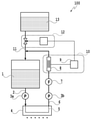
図1は、本実施形態を適用可能な液体吐出装置100の要部を示した模式図である。液体吐出装置100は、装置内で液体(以下、インクともいう)を循環する構成を備えている。液体吐出装置100は、一時的にインクを貯留する循環タンク1と、循環タンク1から供給流路2を介してインクが供給される吐出ヘッド4と、調整液供給路11を介して循環タンク1に調整液を供給する調整液タンク(調整液貯留手段)13とを備えている。更に、本実施形態の液体吐出装置100は、吐出ヘッド4から流出したインクのインピーダンス測定を行うインピーダンスセンサ10と、循環タンク1に供給する調整液の量を制御する調整液制御部12と、を備えている。インピーダンスセンサ10は、インピーダンス検出部8とインピーダンスセンサ制御部9とを備えている。
FIG. 1 is a schematic view showing a main part of a
吐出ヘッド4は、インクを吐出する複数の吐出口を備えており、インクの揮発分蒸発による吐出口近傍におけるインクの組成変化を抑制するため、吐出ヘッド4の吐出口近傍までインクを循環させるヘッド内インク循環路5を備えている。ヘッド内インク循環路5をインクが流れることにより、吐出しない吐出口内のインクも常に循環路内のインクで置換され、インクの急激な濃度変化、粘度変化等が抑制される。供給流路2には、吐出されるインクおよび、吐出はされずに吐出ヘッド4内を循環するインクを合わせた分のインクが流れる。
The
ヘッド内インク循環路5には回収流路(循環流路)6が接続され、吐出ヘッド4内を循環したインクを循環タンク1に戻す。供給流路2および回収流路6にはポンプ3a、3bが設けられ、インク流量や吐出口等におけるインクの圧力を制御する。また、回収流路6におけるインピーダンス検出部8の上流側にはフィルタ7が設けてあり、循環するインク中(液体中)の異物や気泡を除去する。回収流路6は、インピーダンス検出部8の下流で調整液供給路11に接続される。吐出ヘッド内を循環したインクは、フィルタ7、インピーダンス検出部8を通り調整液供給路11に合流して循環タンク1に戻る。
A collection flow path (circulation flow path) 6 is connected to the
調整液供給路11は、蒸発したインクの揮発成分を補充するための調整液を保持する調整液タンク13から調整液制御部12を介して循環タンク1へ接続されている。調整液タンク13から循環タンク1への調整液の供給量は、インピーダンスセンサ10の測定値に基づき、調整液制御部12で制御される。
The adjusting
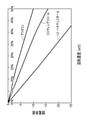
図2は、液体吐出装置に用いられるインクジェット用水系インクの代表的な不揮発性溶剤水溶液の溶剤濃度と比誘電率との関係を示したグラフである。溶剤濃度10%を初期とし、溶剤濃度が上昇した場合に水溶液の比誘電率が初期と比較してどの程度低下するかを示している。通常、インクジェット用水系インクでは、水に10~50%程度の不揮発性溶剤を加えたものを溶媒とする構成が一般的に用いられる。このようなインクにおいて、揮発成分は主に水であり、揮発成分すなわち水が蒸発して不揮発性溶剤の濃度が上昇(水分率低下)すると、それに対応して比誘電率が低下する。そのため温度一定の場合、インクの比誘電率を求めることにより、そのインクの水分率(不揮発性溶剤の濃度)を求めることができる。そして、定まった2つの電極間に存在するインクのインピーダンスは、比誘電率と1対1で対応する。よって、予めインク中の水分率と、その測定系でのインクインピーダンスとの関係を求めることで、インクインピーダンス測定値からその時のインクの水分率を求めることができる。 FIG. 2 is a graph showing the relationship between the solvent concentration and the relative permittivity of a typical non-volatile solvent aqueous solution of an inkjet water-based ink used in a liquid ejection device. The initial setting is 10% of the solvent concentration, and it shows how much the relative permittivity of the aqueous solution decreases as compared with the initial stage when the solvent concentration increases. Usually, in the water-based ink for inkjet, a structure in which a solvent obtained by adding about 10 to 50% of a non-volatile solvent to water is generally used. In such inks, the volatile component is mainly water, and when the volatile component, that is, water evaporates and the concentration of the non-volatile solvent increases (the water content decreases), the relative permittivity decreases correspondingly. Therefore, when the temperature is constant, the moisture content (concentration of the non-volatile solvent) of the ink can be obtained by obtaining the relative permittivity of the ink. The impedance of the ink existing between the two fixed electrodes corresponds to the relative permittivity on a one-to-one basis. Therefore, by obtaining the relationship between the water content in the ink and the ink impedance in the measurement system in advance, the water content of the ink at that time can be obtained from the ink impedance measured value.
ここで、インク濃度や揮発成分率の測定方法としては、一般的に光学的な方法や、電気抵抗率、粘度、密度等の測定等も考えられる。しかし、例えば通常の黒インクは染料や顔料等の色材の影響で広い周波数帯での光の吸収が非常に大きいため、薄めずに濃度を測定することは困難であり、光学的な測定方法をプリンタ等に簡便に組み込むのは容易ではない。また、光を通すための流路中に透明な窓を設ける必要があるが、染料や顔料の窓への付着等、経時でその窓が汚れると測定値が不正確になるという問題がある。 Here, as a method for measuring the ink concentration and the volatile component ratio, generally an optical method, measurement of electrical resistivity, viscosity, density, etc. can be considered. However, for example, ordinary black ink absorbs light in a wide frequency band very much due to the influence of coloring materials such as dyes and pigments, so it is difficult to measure the density without diluting it, and it is an optical measurement method. Is not easy to incorporate into a printer or the like. Further, it is necessary to provide a transparent window in the flow path for passing light, but there is a problem that the measured value becomes inaccurate if the window becomes dirty over time such as adhesion of dye or pigment to the window.
また、電気抵抗率の測定には導電性の電極を直にインクと接する必要があり、さらに電圧が印加されると、電極の耐久性、電気分解や顔料の分散破壊によるインクの変質等の懸念があり、長期安定的な測定には不向きである。また、インク粘度の測定を振動子の共鳴・減衰状態で測定する方法も考えられているが、簡便な方式ではインクジェットインクに多く用いられる数~数10mPa・s程度の粘度では検出精度を上げることが難しい。また、特許文献2の密度計による測定は、先にも述べたように付属装置、回路が複雑で大きく高価である。
In addition, in order to measure the electrical resistance, it is necessary to directly contact the conductive electrode with the ink, and when a voltage is applied, there are concerns about the durability of the electrode, deterioration of the ink due to electrolysis and dispersion destruction of the pigment, etc. Therefore, it is not suitable for long-term stable measurement. In addition, a method of measuring the ink viscosity in the resonance / attenuation state of the vibrator has been considered, but a simple method can improve the detection accuracy at a viscosity of several to several tens of mPa · s, which is often used for inkjet ink. Is difficult. Further, in the measurement by the densitometer of
そこで本実施形態の液体吐出装置100では、循環するインクのインピーダンスを測定することで、インク水分率を求めてインクの蒸発の度合を検知する。上記のような揮発成分率の測定方法と比較して、インピーダンスによる水分率測定では、流路に2つの電極を設け、その電極間に存在するインクの電気的インピーダンスを測定するので、簡便、低コストかつ小型化した構成での測定が可能である。特に、インク揮発成分として最も汎用に使われている水の場合、揮発成分率の変化に対するインク誘電率、すなわち電気的インピーダンスの変化が大きく、精度よく揮発成分率の変化を検出することができる。そして電極が絶縁性保護膜に覆われていれば、インクと接触することによる電極の経時変化も抑制され、低周波で測定しなければインクの変質も生じない。
Therefore, in the
ここではインクの揮発成分が水である水系インクについて述べたが、揮発成分が水以外の場合でも、揮発成分と不揮発成分の比誘電率が異なることが一般的である。揮発成分と不揮発成分の比率が異なればインク比誘電率すなわちインピーダンスの差異となって現れる。通常インクには揮発性、不揮発の溶媒成分に加え、さらに染料、顔料等の色材や、界面活性剤等の添加剤が含まれているが、やはり揮発成分率の変化に対応した比誘電率の変化が生じるため、同様にインピーダンスの測定による揮発成分率の測定が可能である。 Here, the water-based ink in which the volatile component of the ink is water has been described, but even when the volatile component is other than water, the relative permittivity of the volatile component and the non-volatile component is generally different. If the ratio of the volatile component and the non-volatile component is different, it appears as a difference in the relative permittivity of the ink, that is, the impedance. Normally, ink contains volatile and non-volatile solvent components, as well as coloring materials such as dyes and pigments, and additives such as surfactants. However, the relative permittivity also corresponds to changes in the volatile component ratio. Therefore, it is possible to measure the volatile component ratio by measuring the impedance in the same way.
図1に戻り、改めて液体吐出装置100の構成を説明する。フィルタ7の直近の下流には、インピーダンス検出部8が設けられており、インピーダンス検出部8は対向した2つの電極から構成され、その2つの電極間をインクが満たした構成となっている。2つの電極間に気泡等の気体が付着し、かつその体積が電極間体積と比較して無視できない大きさである場合、気体と液体であるインクとの比誘電率差が非常に大きいため、測定されるインピーダンスを大きく変化(低下)させてしまう。そのため、電極間のインクインピーダンス測定に寄与する部分では、できるだけ気泡の混入を避ける必要がある。そのため、電極間を通るインクの流速が速いことが望ましく、その点でインピーダンス検出部8は、循環タンク1等のインク滞留部よりも、供給流路2や回収流路6などのインク流速の速い部分に設置することが望ましい。また、電極面はできるだけインクの流れに平行で、その間を通り抜けるインクの流れを妨げにくい形状が望ましい。
Returning to FIG. 1, the configuration of the
同様に電極への泡付着防止の観点から、インピーダンス検出部8はフィルタ7の下流側近傍への設置が好適である。本実施形態ではフィルタ7、インピーダンス検出部8が回収流路6に設けられているが、これらは供給流路2にあってもよい。ただしその場合にも、インピーダンス検出部8がフィルタ7の下流近傍に設けられることが望ましい。
Similarly, from the viewpoint of preventing bubbles from adhering to the electrodes, it is preferable to install the
インピーダンス検出部8の電極のインクと接する面は、耐インク性があり、かつ絶縁性を有する薄い保護膜で覆われている。インクの残量検知や液面検知にインピーダンスの測定を利用する場合では、インク有無という非常に大きな誘電率変化を検知するだけなので、例えばインピーダンス検出用電極をタンクや流路の外側に設置する場合が考えられる。しかし、本発明ではインクの揮発成分率変化という、より微小な誘電率の変化を捉える必要があるため、電極の絶縁保護膜は薄い方がよい。さらに2つの電極間の間隔も、インクの流れを妨げない範囲で小さくすることが測定感度を向上させる点で望ましい。
The surface of the electrode of the
図3(a)、(b)は、インピーダンス検出部8を示した図であり、図3(a)が縦断面図、図3(b)が横断面図である。回収流路6の途中にインク耐性のある樹脂等から形成された電極容器31が接続されている。電極容器31内側には、表層が耐インク性の薄い絶縁保護膜で覆われた金属からなる電極32が対向するように2枚貼り付けられており、その2枚の電極32の間をインク流34が通り抜ける構成になっている。
3A and 3B are views showing the
インピーダンス検出部8の構成としては、インピーダンスを精度良く測定するため電極32とインクとから形成される静電容量が適度な大きさであること(一般的には100pF以上)、泡付着防止観点から電極間を通り抜けるインク流速が速いことが求められる。更に、インク循環路の一部としてインクがスムーズに流れること、全体の大きさ制限、等を考慮して電極のサイズや間隔を決める必要がある。インピーダンス検出部8の好適な構成としては、例えば電極32の幅W:5mm、長さL:40mm、2つの電極間の間隔d:0.5mmである。
The configuration of the
インピーダンス検出部8の各電極にはリード接続部33が形成されており、ここから配線によって電極32がインピーダンスセンサ制御部9と電気的に接続され、2枚の電極32間に存在するインクのインピーダンス測定が可能となる。インピーダンスセンサ10は、インピーダンス検出部8とインピーダンスセンサ制御部9とが一体となった構成となっている。インピーダンスセンサ制御部9は、測定されたインクのインピーダンスの値に応じ、調整液制御部12へ信号を出力する。
A
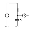
図4は、インピーダンスセンサ10の回路を示した図である。コンデンサCの部分がインピーダンス検出部8に対応し、所定周波数の電圧を印加した際、インピーダンス検出部8両端の電圧を測定することにより検出部のインクのインピーダンスが求められる。
FIG. 4 is a diagram showing a circuit of the
ここで、調整液はインクの揮発成分を主成分とした液であるが、揮発成分だけである必要はなく、例えば初期のインクを揮発成分で希釈したような液等でも構わない。ここでは、一般的な水系インクである、
水/不揮発性溶剤/色材(染料、顔料等)
という構成のインクが使用された場合について説明する。初期のインクで、水が蒸発していない段階でインピーダンスセンサ10を用いて測定したインピーダンス値をZ0、循環で水分が蒸発した後に測定したインピーダンス値をZtとすると、水分蒸発により誘電率は低下するのに対応してインピーダンスは逆に増大する。このことから、ZtとZ0との関係は、
Zt>Z0
の関係になる。そこで、インピーダンスセンサ10の測定値フィードバックをかけながら調整液制御部12を、
Zt>Z0:調整液補充
Zt≦Z0:調整液補充せず
のように制御すれば、インク中の水分率を一定の範囲内に保つことができる。つまり、インク循環においての水分蒸発による濃度増加、粘度増加等の問題を解決することができる。もちろん、循環インクが必要以上に薄くなることを避けるため、調整液制御部12による調整液の供給量や、インピーダンスセンサ10から調整液制御部12へのフィードバック周期などは、使用するインクや使用環境等に応じて適切に設定する必要がある。
Here, the adjusting liquid is a liquid containing the volatile component of the ink as a main component, but it does not have to be only the volatile component, and may be, for example, a liquid obtained by diluting the initial ink with the volatile component. Here, it is a general water-based ink,
Water / non-volatile solvent / coloring material (dye, pigment, etc.)
The case where the ink having the above configuration is used will be described. Assuming that the impedance value measured using the
Zt> Z0
Become a relationship. Therefore, the adjusting
Zt> Z0: Replenishment of adjusting liquid Zt ≦ Z0: By controlling so as not to replenish the adjusting liquid, the water content in the ink can be kept within a certain range. That is, it is possible to solve problems such as an increase in concentration and an increase in viscosity due to evaporation of water in ink circulation. Of course, in order to prevent the circulating ink from becoming thinner than necessary, the amount of the adjusting liquid supplied by the adjusting
このように調整液制御部12は、インピーダンスセンサ10の測定値(検知手段の検知結果)に基づいて、揮発する前のインクのインピーダンス値より測定値が大きければ、所定量の調整液を調整液タンク13から循環タンク1へと供給するよう制御する。調整液制御部12は、調整液供給路11に設けられ、供給路を開閉可能な弁を開閉する弁制御を行うことで、調整液タンク13から循環タンク1への調整液の供給を行う。
As described above, the adjusting
本発明において、インクのインピーダンス測定を行うための好適な周波数としては、100kHz~1GHzである。これより低い周波数では、検出値に対するインク中に溶解している染料あるいは分散している顔料等イオンの寄与が大きくなり、揮発成分蒸発(主にインク溶媒成分の変化)によるインピーダンス差異の検出精度が低下する。また、これより高い周波数では水の吸収による寄与が大きくなって望ましくない。 In the present invention, a suitable frequency for measuring the impedance of the ink is 100 kHz to 1 GHz. At frequencies lower than this, the contribution of ions such as dyes dissolved in the ink or dispersed pigments to the detected value becomes large, and the detection accuracy of the impedance difference due to evaporation of volatile components (mainly changes in the ink solvent component) becomes high. descend. Further, at frequencies higher than this, the contribution of water absorption becomes large, which is not desirable.
液体吐出装置において、インクの液面検知、残量検知でインピーダンスの測定を行うことは従来から実施されている。これは、インクと気体の大きな誘電率差を利用したものであり、これらの方式では、ある場合においてインピーダンス測定用電極間にインクだけではなく気体が存在することが前提になっている。 In a liquid ejection device, it has been conventionally practiced to measure impedance by detecting the liquid level of ink and detecting the remaining amount of ink. This utilizes a large dielectric constant difference between the ink and the gas, and in these methods, it is premised that not only the ink but also the gas exists between the electrodes for impedance measurement in some cases.
一方、本発明の場合、測定部電極間に気体が入ることは望ましくない。インク揮発成分率変化による誘電率(インピーダンス)変化に比べて、インク-気体の変化による誘電率変化の方がはるかに大きく、間に気体が入るとインクの揮発成分蒸発による変化の検出が困難になってしまうためである。そのため、本発明におけるインピーダンス検出用電極は、出来るだけ電極間に気体(気泡など)の入りにくい箇所に設置することが望ましい。そのため、インクが滞留し、気体が存在するタンク部分よりも、インク供給流路や回収流路等インク流速が早い部分が望ましい設置箇所である。さらに泡の付着を抑制するため、測定部の対向電極はインクの流れに対し略平行に設置されることが望ましい。 On the other hand, in the case of the present invention, it is not desirable for gas to enter between the electrodes of the measuring unit. The change in permittivity due to the change in ink-gas is much larger than the change in permittivity (impedance) due to the change in the volatile component rate of the ink, and it becomes difficult to detect the change due to evaporation of the volatile component of the ink when a gas enters between them. This is because it becomes. Therefore, it is desirable that the impedance detection electrode in the present invention be installed in a place where gas (air bubbles, etc.) is difficult to enter between the electrodes as much as possible. Therefore, a portion where the ink flow rate is faster, such as an ink supply flow path and a recovery flow path, is a desirable installation location than a tank portion where ink stays and gas is present. Further, in order to suppress the adhesion of bubbles, it is desirable that the counter electrode of the measuring unit is installed substantially parallel to the ink flow.
同様に測定部への泡付着防止の観点から、本発明のインピーダンスセンサは、インク循環路内に存在するフィルタ7の下流近傍が設置に好適な箇所である。
Similarly, from the viewpoint of preventing bubbles from adhering to the measuring unit, the impedance sensor of the present invention is suitable for installation in the vicinity of the downstream side of the
さらにインクのインピーダンス測定は、例えば同一周波数での測定を一定間隔おいて複数回繰り返し(複数回測定)、その中での最小値をインクのインピーダンス測定値として認識するようなシーケンスを用いることが好適である。これは、万一循環路中に気泡が紛れ込み、その気泡のインピーダンス検出部8の電極への付着・剥離が考えられる場合、インピーダンスの最小値が最も気泡の影響が小さい場合の値と考えられるためである。
Further, for the impedance measurement of the ink, for example, it is preferable to use a sequence in which the measurement at the same frequency is repeated multiple times at regular intervals (measurement multiple times) and the minimum value among them is recognized as the impedance measurement value of the ink. Is. This is considered to be the value when the minimum value of the impedance is the smallest influence of the bubble in the case where the bubble is mixed in the circulation path and the bubble is considered to be attached or detached to the electrode of the
このように、インクのインピーダンスを測定し、その測定結果に基づいて、循環するインクに調整液を供給する。これによって、インクタンクと吐出ヘッドとの間でインクを循環させる構成の液体吐出装置で、簡易で安価な小型の構成で吐出特性の悪化を抑制することができる液体吐出装置を実現することができた。 In this way, the impedance of the ink is measured, and the adjusting liquid is supplied to the circulating ink based on the measurement result. As a result, it is possible to realize a liquid ejection device having a configuration in which ink is circulated between the ink tank and the ejection head, and which can suppress deterioration of ejection characteristics with a simple, inexpensive and compact configuration. rice field.
(第2の実施形態)
以下、図面を参照して本発明の第2の実施形態を説明する。なお、本実施形態の基本的な構成は第1の実施形態と同様であるため、以下では特徴的な構成についてのみ説明する。
(Second embodiment)
Hereinafter, a second embodiment of the present invention will be described with reference to the drawings. Since the basic configuration of this embodiment is the same as that of the first embodiment, only the characteristic configuration will be described below.
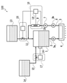
図5は、本実施形態における液体吐出装置100の要部を示した模式図である。本実施形態の液体吐出装置100は、第1の実施形態の液体吐出装置100の構成に加え、インピーダンスおよび温度センサ20と、循環タンク1にインクを補給するためにメインタンク14およびインク補給路15と、を備えている。インピーダンスおよび温度センサ20は、インピーダンス検出部8と、インクの温度検出を行う(温度を検出可能な)温度検出部18と、インピーダンスセンサと温度センサとの両方を制御するインピーダンス及び温度センサ制御部19とを備えている。インピーダンスおよび温度センサ20は、インクのインピーダンスに加え、その時のインク温度を測定する。
FIG. 5 is a schematic view showing a main part of the
インクの誘電率は温度により変化するので、インピーダンスの測定値も温度によって変化する。インピーダンス測定時のインクの温度を測定することにより、測定値に温度補正を加えることが可能となり、より正確な制御が可能となる。 Since the dielectric constant of the ink changes with temperature, the measured impedance also changes with temperature. By measuring the temperature of the ink at the time of impedance measurement, it is possible to add temperature correction to the measured value, and more accurate control becomes possible.
例えば、初期インクのインピーダンス測定値Z0の温度T依存性Z0Tを予め測定しておく。実際の循環路中のインピーダンス測定値がZtであり、その時のインク温度がT1だった場合、同じ温度T1の初期インクのインピーダンスZ0T1と比較し、
Zt>Z0T1:調整液補充
Zt≦Z0T1:調整液補充せず
のように制御をすればよい。環境温度その他でインク温度が変化した場合にもより正確にインク揮発成分率の制御が可能になり、インクの濃度や粘度増加等に起因する画像の不良発生を抑制することができる。
For example, the temperature T-dependent Z0 T of the impedance measurement value Z0 of the initial ink is measured in advance. When the measured impedance value in the actual circulation path is Zt and the ink temperature at that time is T1, it is compared with the impedance Z0 T1 of the initial ink having the same temperature T1.
Zt> Z0 T1 : Replenishment of adjusting liquid Zt ≦ Z0 T1 : Control may be performed so as not to replenish the adjusting liquid. Even when the ink temperature changes due to the environmental temperature or the like, the ink volatile component ratio can be controlled more accurately, and the occurrence of image defects due to an increase in ink density or viscosity can be suppressed.
またメインタンク14は循環タンク1にインクを供給可能であり、メインタンク14から循環タンク1に供給されるインクは、循環タンク1に設けられた液面センサ16の測定値に基づいてインク補給量を制御するインク補給制御部17により補給量が制御される。このように、インク補給システムを加えることにより液体吐出装置の使用可能時間を大きく延長することができる。
Further, the
1 循環タンク
2 供給流路
4 吐出ヘッド
6 回収流路
8 インピーダンス検出部
9 インピーダンスセンサ制御部
10 インピーダンスセンサ
100 液体吐出装置
1
Claims (16)
循環する液体のインピーダンスを測定することで、液体の揮発成分率を検知する検知手段と、
前記検知手段の検知結果に基づいて、循環する液体の成分の調整を行う調整手段と、
を備えていることを特徴とする液体吐出装置。 A circulating flow that is a flow path of a liquid that circulates between the first storage means for storing the liquid, the discharge means for discharging the liquid supplied from the first storage means, and the first storage means and the discharge means. In a liquid discharge device equipped with a road,
A detection means that detects the volatile component ratio of a liquid by measuring the impedance of the circulating liquid,
An adjusting means for adjusting the components of the circulating liquid based on the detection result of the detecting means, and an adjusting means.
A liquid discharge device characterized by being equipped with.
循環する液体のインピーダンスを測定する測定手段と、
前記測定手段の測定結果に基づいて、循環する液体の成分の調整を行う調整手段と、
を備えていることを特徴とする液体吐出装置。 A circulating flow that is a flow path of a liquid that circulates between the first storage means for storing the liquid, the discharge means for discharging the liquid supplied from the first storage means, and the first storage means and the discharge means. In a liquid discharge device equipped with a road,
A measuring means for measuring the impedance of a circulating liquid,
An adjusting means for adjusting the components of the circulating liquid based on the measurement result of the measuring means, and an adjusting means.
A liquid discharge device characterized by being equipped with.
Priority Applications (3)
| Application Number | Priority Date | Filing Date | Title |
|---|---|---|---|
| JP2018002017A JP6991864B2 (en) | 2018-01-10 | 2018-01-10 | Liquid discharge device |
| US16/226,388 US10618303B2 (en) | 2018-01-10 | 2018-12-19 | Liquid ejection apparatus |
| CN201910017525.9A CN110014741B (en) | 2018-01-10 | 2019-01-09 | Liquid ejecting apparatus |
Applications Claiming Priority (1)
| Application Number | Priority Date | Filing Date | Title |
|---|---|---|---|
| JP2018002017A JP6991864B2 (en) | 2018-01-10 | 2018-01-10 | Liquid discharge device |
Publications (3)
| Publication Number | Publication Date |
|---|---|
| JP2019119179A JP2019119179A (en) | 2019-07-22 |
| JP2019119179A5 JP2019119179A5 (en) | 2021-02-04 |
| JP6991864B2 true JP6991864B2 (en) | 2022-01-13 |
Family
ID=67140409
Family Applications (1)
| Application Number | Title | Priority Date | Filing Date |
|---|---|---|---|
| JP2018002017A Active JP6991864B2 (en) | 2018-01-10 | 2018-01-10 | Liquid discharge device |
Country Status (3)
| Country | Link |
|---|---|
| US (1) | US10618303B2 (en) |
| JP (1) | JP6991864B2 (en) |
| CN (1) | CN110014741B (en) |
Families Citing this family (2)
| Publication number | Priority date | Publication date | Assignee | Title |
|---|---|---|---|---|
| CN110271297B (en) * | 2019-07-24 | 2020-08-04 | 深圳市华星光电半导体显示技术有限公司 | Ink-jet printing system, ink-jet printing method and display panel |
| KR20250058858A (en) * | 2023-10-23 | 2025-05-02 | 삼성디스플레이 주식회사 | Inkjet printing device |
Citations (4)
| Publication number | Priority date | Publication date | Assignee | Title |
|---|---|---|---|---|
| JP2002241653A (en) | 2001-02-14 | 2002-08-28 | Sharp Corp | Aqueous pigment ink for recording, its manufacturing apparatus and its manufacturing method |
| JP2007237706A (en) | 2006-03-13 | 2007-09-20 | Seiko Epson Corp | Liquid ejector |
| JP2014523356A (en) | 2011-10-24 | 2014-09-11 | ヒューレット−パッカード デベロップメント カンパニー エル.ピー. | Fluid ejecting apparatus and method |
| US20170144448A1 (en) | 2015-11-25 | 2017-05-25 | Videojet Technologies, Inc. | Ink quality sensor and a condition monitoring system for an inkjet printer |
Family Cites Families (10)
| Publication number | Priority date | Publication date | Assignee | Title |
|---|---|---|---|---|
| ATE171897T1 (en) | 1990-02-26 | 1998-10-15 | Canon Kk | RECORDING DEVICE AND METHOD FOR INK DETECTION |
| JPH03275360A (en) * | 1990-03-26 | 1991-12-06 | Seiko Epson Corp | Ink end detection method for inkjet recording devices |
| ATE142563T1 (en) | 1990-11-30 | 1996-09-15 | Canon Kk | INK JET PRINT HEAD WITH CONTROL CIRCUIT THEREOF |
| JPH07117233A (en) | 1993-10-26 | 1995-05-09 | Toray Ind Inc | Method for controlling physical properties of ink in inkjet recording apparatus |
| US5583544A (en) * | 1994-10-06 | 1996-12-10 | Videojet Systems International, Inc. | Liquid level sensor for ink jet printers |
| JP2007090558A (en) * | 2005-09-27 | 2007-04-12 | Canon Finetech Inc | Inkjet recording device and ink detection method of the device |
| US8534807B2 (en) | 2008-05-23 | 2013-09-17 | Fujifilm Corporation | Fluid droplet ejection systems having recirculation passages |
| JP5257139B2 (en) * | 2009-02-26 | 2013-08-07 | 株式会社リコー | Image forming apparatus |
| JP6608240B2 (en) | 2015-10-22 | 2019-11-20 | キヤノン株式会社 | Liquid ejection device |
| JP6851800B2 (en) * | 2016-01-08 | 2021-03-31 | キヤノン株式会社 | Liquid discharge device and liquid discharge head |
-
2018
- 2018-01-10 JP JP2018002017A patent/JP6991864B2/en active Active
- 2018-12-19 US US16/226,388 patent/US10618303B2/en active Active
-
2019
- 2019-01-09 CN CN201910017525.9A patent/CN110014741B/en active Active
Patent Citations (4)
| Publication number | Priority date | Publication date | Assignee | Title |
|---|---|---|---|---|
| JP2002241653A (en) | 2001-02-14 | 2002-08-28 | Sharp Corp | Aqueous pigment ink for recording, its manufacturing apparatus and its manufacturing method |
| JP2007237706A (en) | 2006-03-13 | 2007-09-20 | Seiko Epson Corp | Liquid ejector |
| JP2014523356A (en) | 2011-10-24 | 2014-09-11 | ヒューレット−パッカード デベロップメント カンパニー エル.ピー. | Fluid ejecting apparatus and method |
| US20170144448A1 (en) | 2015-11-25 | 2017-05-25 | Videojet Technologies, Inc. | Ink quality sensor and a condition monitoring system for an inkjet printer |
Also Published As
| Publication number | Publication date |
|---|---|
| JP2019119179A (en) | 2019-07-22 |
| US10618303B2 (en) | 2020-04-14 |
| US20190210375A1 (en) | 2019-07-11 |
| CN110014741A (en) | 2019-07-16 |
| CN110014741B (en) | 2021-02-12 |
Similar Documents
| Publication | Publication Date | Title |
|---|---|---|
| RU2635080C2 (en) | Device for emission of fluid environment with built-in ink level sensor | |
| US10378946B2 (en) | Ink level sensing | |
| KR950001101B1 (en) | Ink jet head, ink tank, ink jet recording device, ink residual amount detection method and ink residual amount detection device | |
| RU2572766C2 (en) | Fluid medium level sensor and related methods | |
| US10618301B2 (en) | Semiconductor device including capacitive sensor and ion-sensitive transistor for determining level and ion-concentration of fluid | |
| EP0597628B1 (en) | Ink replenishment system for a continuous ink jet printer | |
| US9707771B2 (en) | Fluid ejection device with integrated ink level sensors | |
| CN106061743B (en) | Liquid ejection device with ground electrode exposed to liquid chamber | |
| JP6991864B2 (en) | Liquid discharge device | |
| US8651622B2 (en) | Recording apparatus | |
| JP7669156B2 (en) | Image Recording Device | |
| US10265965B2 (en) | Image recording apparatus and cartridge | |
| US5724076A (en) | Out-of-ink detector and ink jet printer | |
| US12030310B2 (en) | Maintenance routines | |
| JP2003072096A (en) | Inkjet recording device | |
| US20200298584A1 (en) | Fluid reservoir impedance sensors |
Legal Events
| Date | Code | Title | Description |
|---|---|---|---|
| A521 | Written amendment |
Free format text: JAPANESE INTERMEDIATE CODE: A523 Effective date: 20201217 |
|
| A621 | Written request for application examination |
Free format text: JAPANESE INTERMEDIATE CODE: A621 Effective date: 20201217 |
|
| TRDD | Decision of grant or rejection written | ||
| A01 | Written decision to grant a patent or to grant a registration (utility model) |
Free format text: JAPANESE INTERMEDIATE CODE: A01 Effective date: 20211109 |
|
| A61 | First payment of annual fees (during grant procedure) |
Free format text: JAPANESE INTERMEDIATE CODE: A61 Effective date: 20211208 |
|
| R151 | Written notification of patent or utility model registration |
Ref document number: 6991864 Country of ref document: JP Free format text: JAPANESE INTERMEDIATE CODE: R151 |