JP6991855B2 - Header plateless heat exchanger - Google Patents
Header plateless heat exchanger Download PDFInfo
- Publication number
- JP6991855B2 JP6991855B2 JP2017251880A JP2017251880A JP6991855B2 JP 6991855 B2 JP6991855 B2 JP 6991855B2 JP 2017251880 A JP2017251880 A JP 2017251880A JP 2017251880 A JP2017251880 A JP 2017251880A JP 6991855 B2 JP6991855 B2 JP 6991855B2
- Authority
- JP
- Japan
- Prior art keywords
- heat exchanger
- plates
- laminated
- flat tube
- fluid
- Prior art date
- Legal status (The legal status is an assumption and is not a legal conclusion. Google has not performed a legal analysis and makes no representation as to the accuracy of the status listed.)
- Expired - Fee Related
Links
Images


Landscapes
- Heat-Exchange Devices With Radiators And Conduit Assemblies (AREA)
Description
本発明は、主として排気ガスを冷却水で冷却するEGRクーラや、排気ガスの熱を冷却し回収する排熱回収器に最適な熱交換器であって、ヘッダープレートレス型のコアを有するものに関する。
なお、ヘッダープレートレス型のコアとは、偏平チューブの開口端を厚み方向に膨出したものを使用し、その膨出部において各偏平チューブを積層することにより、ヘッダープレートを不要としたものである。
The present invention relates to an EGR cooler that mainly cools an exhaust gas with cooling water and a heat exchanger that is most suitable for an exhaust heat recovery device that cools and recovers the heat of the exhaust gas and has a header plateless type core. ..
The header plateless type core is a core in which the open end of the flat tube is bulged in the thickness direction, and each flat tube is laminated at the bulging portion to eliminate the need for a header plate. be.
下記特許文献1にヘッダープレートレス型熱交換器が提案されている。
この熱交換器は、そのコアを形成する偏平チューブが、一対の溝型に形成されたプレートを互いに溝底を対向して嵌着したものからなり、その両端開放側の縁に膨出部が形成され、その膨出部において各偏平チューブを積層し、各プレート間を一体にろう付固定したものである。
A header plateless heat exchanger is proposed in
In this heat exchanger, the flat tubes forming the core are fitted with a pair of groove-shaped plates facing each other at the bottoms of the grooves, and bulges are formed on the edges on the open sides of both ends. Each flat tube is laminated at the bulging portion thereof, and the plates are integrally brazed and fixed.
従来のヘッダープレートレス型熱交換器は、排気ガスの入口部において、各偏平チューブが高温となり、繰り返し生じるヒートサイクルにより熱交換器が劣化するおそれがある。
これは、ヘッダープレートレス型熱交換器の特徴として構造が簡単になる利点を有するも、欠点として、ヘッダープレートを有する熱交換器に比べて、各偏平チューブの先端部の冷却性が悪くその部分が高温となるからである。
そこで、本発明はヘッダープレートレスの利点を有しつつ、可能な限り偏平チューブの先端部の温度を低下できる熱交換器を提供することを課題とする。
In the conventional header plateless heat exchanger, each flat tube becomes hot at the inlet of the exhaust gas, and the heat exchanger may deteriorate due to repeated heat cycles.
This has the advantage that the structure is simplified as a feature of the header plateless heat exchanger, but the disadvantage is that the cooling property of the tip of each flat tube is poorer than that of the heat exchanger having the header plate. Is high temperature.
Therefore, it is an object of the present invention to provide a heat exchanger capable of lowering the temperature of the tip end portion of the flat tube as much as possible while having the advantage of the header plateless.
請求項1に記載の本発明は、それぞれ両側に一対の側壁1が立上げられて全体が溝状に形成され且つ、その側壁 に直交した溝底3の両開放側の縁に厚み方向外側に細幅の膨出部4が形成されている一対のプレート5,6を有し、それらのプレート5,6が互いに逆向きに対向して嵌着されている偏平チューブ7と、
複数の偏平チューブ7が膨出部4で互いに積層され、各プレート5,6が互いにろう付されている熱交換器コア13と、を有し、
各偏平チューブの前記膨出部4の先端から第一流体19が内部に流入し、その 外側に第二流体18が流通する熱交換器であって、
前記各プレート5,6の前記膨出部4には、前記外側にそれぞれ折返されて、略全長に渡り両外面に第1重合部10が形成されており、各偏平チューブ7がその第1重合部10で、4枚重ねに積層されており、その積層部がろう付されており、
前記各プレート5,6の前記第1重合部10が、前記第1重合部10の長手方向の両端部で広い幅に形成されており、それ以外の中間部で狭い幅に形成されていることを特徴とするヘッダープレートレス型熱交換器である。
According to the first aspect of the present invention, a pair of
A plurality of
A heat exchanger in which the
The bulging
The
請求項2に記載の本発明は、それぞれ両側に一対の側壁1が立上げられて全体が溝状に形成され且つ、その側壁 に直交した溝底3の両開放側の縁に厚み方向外側に細幅の膨出部4が形成されている一対のプレート5,6を有し、それらのプレート5,6が互いに逆向きに対向して嵌着されている偏平チューブ7と、
複数の偏平チューブ7が膨出部4で互いに積層され、各プレート5,6 が互いにろう付されている熱交換器コア13と、を有し、
各偏平チューブの前記膨出部4の先端から第一流体19が内部に流入し、その 外側に第二流体18が流通する熱交換器であって、
前記各プレート5,6の前記膨出部4には、前記細幅の長手方向に両端部を除き、前記外側にそれぞれ横断面U字状に折返されたU字部11が形成され、各偏平チューブ7がそのU字部11で、積層されており、
前記細幅の長手方向の両端部では、積層された各偏平チューブ7の前記膨出部4が外側に折返されて、その折返し部が重ね合わされた第2重合部12を形成しており、
その第2重合部12と前記U字部11の各表面が面一に形成されており、各偏平チューブが第2重合部12と前記U字部11で互いにろう付されており、
前記U字部11の内側には、第二流体18が流通する冷却水路15が形成されていることを特徴とするヘッダープレートレス型熱交換器である。
According to the second aspect of the present invention, a pair of
A plurality of
A heat exchanger in which the
The bulging
At both ends of the narrow length in the longitudinal direction, the bulging
The surfaces of the
A header plateless heat exchanger characterized in that a
請求項1に記載の発明は、各プレート5,6の膨出部4が、外側にそれぞれ折返されて、第1重合部10が形成されており、各偏平チューブ7がその第1重合部10で、4枚重ねに積層されており、その積層部が互いにろう付されていることを特徴とする。
それにより、膨出部4の剛性が向上するので、当該膨出部に必要な剛性を確保した上で当該部の幅を狭くすることができる。
また、膨出部4近傍の第二流体の流路断面形状が略矩形状となり広がるので、当該近傍の第二流体の流量が増加し、前記先端部と第二流体との伝熱が向上し、温度差が抑制される。これらの結果、ヒートサイクルによる熱交換器の劣化が抑制され、熱交換器の耐久性が向上する。
さらに、各プレート5,6の前記第1重合部10が、前記第1重合部10の長手方向の両端部で広い幅に形成されており、それ以外の中間部で狭い幅に形成されている。
第1重合部10の長手方向の中間部の幅を狭くすることによって、各偏平チューブ7の先端から第二流体までの距離が短くなるので、その先端部と第二流体との伝熱が向上し、その間の温度差が抑制される。
その結果、ヒートサイクルによる熱交換器の劣化がさらに抑制され、熱交換器の耐久性が向上する。
In the invention according to
As a result, the rigidity of the bulging
Further, since the cross-sectional shape of the flow path of the second fluid in the vicinity of the bulging
Further, the
By narrowing the width of the intermediate portion in the longitudinal direction of the
As a result, deterioration of the heat exchanger due to the heat cycle is further suppressed, and the durability of the heat exchanger is improved.
請求項2に記載の発明は、各プレート5,6の膨出部4に、細幅の長手方向に両端部を除き、外側にそれぞれ横断面U字状に折返されてU字部11が形成され、各偏平チューブ7がそのU字部11で、積層されており、膨出する細幅の長手方向の両端部では、積層された各偏平チューブ7が外側に折返されて第2重合部12を形成し、その第2重合部12の外面とU字部11の外面とが面一に形成され、各偏平チューブが第2重合部12とU字部11で互いにろう付されており、U字部11の内側には、第二流体18が流通する冷却水路15が形成されているものである。
それにより、U字部11の内側に第二流体が流通することになり、膨出部4と第二流体との伝熱が向上するので、各偏平チューブ7の先端部と第二流体との温度差が抑制される。その結果、ヒートサイクルによる熱交換器の劣化が抑制され、熱交換器の耐久性が向上する。
According to the second aspect of the present invention, the U-shaped
As a result, the second fluid flows inside the
次に、図面に基づいて本発明の実施の形態につき説明する。
本発明の熱交換器は、主としてEGRクーラ等に使用できるものである。各実施形態の説明において、排気ガス19は第一流体であり、冷却水18は第二流体に相当する。
Next, an embodiment of the present invention will be described with reference to the drawings.
The heat exchanger of the present invention can be mainly used for an EGR cooler or the like. In the description of each embodiment, the
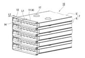
図1~図5は本発明の第1実施例の熱交換器コア13及び、同コアを有する熱交換器の分解斜視図である。
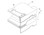
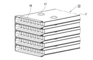
この熱交換器コア13は、図3に示す、偏平チューブ7を積層したものからなる。各偏平チューブ7は、図1に示す如く、両側に一対の側壁1が立ち上げられて全体が溝状に形成され且つ、その両側に直交した溝底3の両開放側(偏平チューブ7の開口端が形成される側)の縁に厚み方向外側に細幅の膨出部4が形成された一対のプレート5,6を有する。そして、そのプレート5,6を互いに逆向きに対向して嵌着し偏平チューブ7を形成する。その偏平チューブ7を複数膨出部4で互いに積層して、熱交換器コア13が形成されている。
1 to 5 are exploded perspective views of the
The
(実施例1の特徴)
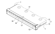
ここにおいて、熱交換器コア13を構成する偏平チューブ7の特徴は、各プレート5,6の両端開放側において、膨出部4に隣接して膨出部4の長手方向の長さに整合する帯状部が膨出部4と一体に設けられており、その帯状部が膨出部4の外側に夫々折り返されて、略全長に渡り外面側に第1重合部10が形成される。
この例では、その第1重合部10はその長手方向の両端において幅広の幅L2となり、それ以外では幅狭の幅L1に形成されている。これは、偏平チューブ7の入口側において、高温の排気ガスが内部に流入すると、特に第1重合部10の長手方向の中間部においてより高温となるので、第1重合部10の縁幅を狭くして、外側に流通する冷却水による冷却効果を高めるものである。
(Characteristics of Example 1)
Here, the feature of the
In this example, the
また、幅広の幅L2と幅狭の幅L1との間は、図2および図3に示すごとく、なだらかに湾曲させることが好ましい。なだらかに湾曲させることにより、なだらかに湾曲していないときより側壁近傍の熱応力の集中が緩和される。
各偏平チューブ7はその膨出部4において積層され、各積層部は厚み方向に4重になる。すると、その厚み分だけ各偏平チューブ7の外面側の冷却水路15の流路が広くなる。
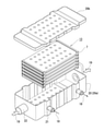
そして図5に示す如く、ケーシング本体20aと端蓋20bとからなるケーシング20内に偏平チューブ7の積層体からなる熱交換器コア13が挿入される。ケーシング20の熱交換器コア13に対向する位置には一対の水パイプ21が配置される。
Further, it is preferable to gently bend the space between the wide width L2 and the narrow width L1 as shown in FIGS. 2 and 3. By gently curving, the concentration of thermal stress near the side wall is relaxed as compared with when it is not gently curved.
Each
Then, as shown in FIG. 5, the
また、ケーシング20の両端にはガスパイプ22が配置される。そして、全体を組立てた状態で高温の炉内に挿入され、全体が一体的にろう付固定されて熱交換器を完成する。なお、ろう付の前に各部品の少なくとも一方側にはろう材を被覆又は塗布しておくと良い。
完成された熱交換器には、一方のガスパイプ22から排気ガス(第一流体)19が流入し、各偏平チューブ7の内部を通り、他方のガスパイプ22からそれが流出する。それと共に、一方の水パイプ21から冷却水(第二流体)18を流入し、各偏平チューブ7の外面側を流通させて、他方の水パイプ21からそれを流出させる。そして排気ガス19と冷却水18との間に熱交換を行うものである。
Further,
Exhaust gas (first fluid) 19 flows into the completed heat exchanger from one
(実施例1の作用)
この実施例では、膨出部4が折り返されて、そこに第1重合部10が形成されるため、偏平チューブ7の先端部の強度が向上する。それと共に、各偏平チューブ7の第1重合部10どうしが重ねあわされて、偏平チューブ7外面側の冷却水路15が厚み方向に広くなり冷却効果が増大する。さらには、第1重合部10の端部における幅L2よりも中間部の幅L1を狭くしたため、特に、高温になりがちな第1重合部10の中間部の冷却を効果的に行うことができる。さらには、板厚の2倍に折り返された膨出部4により、偏平チューブ7の端部の劣化を防止し、耐久性の高い熱交換器を形成することができる。
(Action of Example 1)
In this embodiment, the bulging
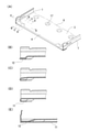
次に、図6~図9は本発明の第2実施例である。
この実施例は、図6,図7に示す如く、両端部を除き、各偏平チューブ7が横断面U字状に形成されたU字部11を有する。
そして膨出部4の長手方向両端部には第2重合部12が形成されている。即ち、図8(B)に示す如く、膨出部4の長手方向両端部では折り返されて、その折り返し部が板厚2枚分に形成され、それ以外の大部分では図8(D)の如く、U字部11に形成されている。
Next, FIGS. 6 to 9 are the second embodiment of the present invention.
As shown in FIGS. 6 and 7, this embodiment has a
なお、U字部11の表面と第2重合部12の表面とは同一平面上にある。即ち、外面が面一に形成されている。このような一対のプレート5,6で構成された偏平チューブ7が積層され熱交換器コア13を形成する。
この熱交換器コア13は、実施例1と同様に、ケーシング20に挿入され、全体が一体的にろう付固定されて熱交換器が完成される。
The surface of the
The
(実施例2の作用)
このような偏平チューブ7は、その膨出部4のU字部11と第2重合部12とが面一に形成される。即ち、膨出部4の長手方向両端においては、第2重合部12が形成され、それ以外ではU字部11に形成される。そして、各偏平チューブ7が隙間なく積層される。その第2重合部12においては、実施例1と同様、その端部強度が向上する。そして、U字部11においては夫々U字状の冷却水路15が形成され、各偏平チューブ7の外面側を流通する冷却水(第二流体)18がそこに導かれる。
そのため、実施例2ではその偏平チューブ7の端部における冷却効果が、実施例1に比べて著しく高い。
(Action of Example 2)
In such a
Therefore, in Example 2, the cooling effect at the end of the
本発明の熱交換器コアは、EGRクーラとして用いることができると共に、他の各種熱交換器、例えば排熱回収器等に利用することもできる。 The heat exchanger core of the present invention can be used as an EGR cooler, and can also be used for various other heat exchangers such as an exhaust heat recovery device.
1 側壁
3 溝底
4 膨出部
5,6 プレート
7 偏平チューブ
10 第1重合部
11 U字部
12 第2重合部
13 熱交換器コア
14 インナーフィン
1
15 冷却水路
16 排気ガス路
17 ディンプル
18 冷却水(第二流体)
19 排気ガス(第一流体)
20 ケーシング
20a ケーシング本体
20b 端蓋
21 水パイプ
22 ガスパイプ
L1 幅
L2 幅
15
19 Exhaust gas (first fluid)
20
Claims (2)
複数の偏平チューブ(7)が膨出部(4)で互いに積層され、各プレート(5)(6)が互いにろう付されている熱交換器コア(13)と、を有し、
各偏平チューブの前記膨出部(4)の先端から第一流体(19)が内部に流入し、その 外側に第二流体(18)が流通する熱交換器であって、
前記各プレート(5)(6)の前記膨出部(4)には、前記外側にそれぞれ折返されて、略全長に渡り両外面に第1重合部(10)が形成されており、各偏平チューブ(7)がその第1重合部(10)で、4枚重ねに積層されており、その積層部がろう付されており、
前記各プレート(5)(6)の前記第1重合部(10)が、前記第1重合部(10)の長手方向の両端部で広い幅に形成されており、それ以外の中間部で狭い幅に形成されていることを特徴とするヘッダープレートレス型熱交換器。 A pair of side walls (1) are erected on both sides to form a groove as a whole, and a narrow bulge outward in the thickness direction on both open side edges of the groove bottom (3) orthogonal to the side wall. A flat tube (7) having a pair of plates (5) and (6) on which (4) is formed, to which the plates (5) and (6) are fitted so as to face each other in opposite directions.
A plurality of flat tubes (7) are laminated with each other at a bulge (4), and each plate (5) (6) has a heat exchanger core (13) to which the plates (5) and (6) are brazed to each other.
A heat exchanger in which the first fluid (19) flows inward from the tip of the bulging portion (4) of each flat tube, and the second fluid (18) flows to the outside thereof.
The bulging portion (4) of each of the plates (5) and (6) is folded back to the outside to form a first polymerization portion (10) on both outer surfaces over substantially the entire length, and each flattened portion (10) is formed. The tube (7) is laminated in four layers at the first polymerization portion (10), and the laminated portion is brazed .
The first polymerized portion (10) of each of the plates (5) and (6) is formed to have a wide width at both ends in the longitudinal direction of the first polymerized portion (10), and is narrow in the other intermediate portions. A header plateless heat exchanger characterized by being formed in width .
複数の偏平チューブ(7)が膨出部(4)で互いに積層され、各プレート(5)(6) が互いにろう付されている熱交換器コア(13)と、を有し、
各偏平チューブの前記膨出部(4)の先端から第一流体(19)が内部に流入し、その 外側に第二流体(18)が流通する熱交換器であって、
前記各プレート(5)(6)の前記膨出部(4)には、前記細幅の長手方向に両端部を除き、前記外側にそれぞれ横断面U字状に折返されたU字部(11)が形成され、各偏平チューブ(7)がそのU字部(11)で、積層されており、
前記細幅の長手方向の両端部では、積層された各偏平チューブ(7)の前記膨出部(4)が外側に折返されて、その折返し部が重ね合わされた第2重合部(12)を形成しており、
その第2重合部(12)と前記U字部(11)の各表面が面一に形成されており、各偏平チューブが第2重合部(12)と前記U字部(11)で互いにろう付されており、
前記U字部(11)の内側には、第二流体(18)が流通する冷却水路(15)が形成されていることを特徴とするヘッダープレートレス型熱交換器。 A pair of side walls (1) are erected on both sides to form a groove as a whole, and a narrow bulge outward in the thickness direction on both open side edges of the groove bottom (3) orthogonal to the side wall. A flat tube (7) having a pair of plates (5) and (6) on which (4) is formed, to which the plates (5) and (6) are fitted so as to face each other in opposite directions.
It has a heat exchanger core (13), in which a plurality of flat tubes (7) are laminated together at a bulge (4) and each plate (5) (6) is brazed to each other.
A heat exchanger in which the first fluid (19) flows inward from the tip of the bulging portion (4) of each flat tube, and the second fluid (18) flows to the outside thereof.
The bulging portion (4) of each of the plates (5) and (6) has a U-shaped portion (11) folded back in a U-shape in cross section to the outside, except for both ends in the longitudinal direction of the narrow width. ) Is formed, and each flat tube (7) is laminated at its U-shaped portion (11).
At both ends of the narrow length in the longitudinal direction, the bulging portion (4) of each of the laminated flat tubes (7) is folded outward, and the second overlapping portion (12) on which the folded portion is overlapped is formed. Forming and
The surfaces of the second polymerized portion (12) and the U-shaped portion (11) are formed flush with each other, and the flat tubes are brazed to each other at the second polymerized portion (12) and the U-shaped portion (11). Is attached ,
A header plateless heat exchanger characterized in that a cooling water channel (15) through which a second fluid (18) flows is formed inside the U-shaped portion (11) .
Priority Applications (1)
| Application Number | Priority Date | Filing Date | Title |
|---|---|---|---|
| JP2017251880A JP6991855B2 (en) | 2017-12-27 | 2017-12-27 | Header plateless heat exchanger |
Applications Claiming Priority (1)
| Application Number | Priority Date | Filing Date | Title |
|---|---|---|---|
| JP2017251880A JP6991855B2 (en) | 2017-12-27 | 2017-12-27 | Header plateless heat exchanger |
Publications (2)
| Publication Number | Publication Date |
|---|---|
| JP2019117032A JP2019117032A (en) | 2019-07-18 |
| JP6991855B2 true JP6991855B2 (en) | 2022-01-13 |
Family
ID=67304268
Family Applications (1)
| Application Number | Title | Priority Date | Filing Date |
|---|---|---|---|
| JP2017251880A Expired - Fee Related JP6991855B2 (en) | 2017-12-27 | 2017-12-27 | Header plateless heat exchanger |
Country Status (1)
| Country | Link |
|---|---|
| JP (1) | JP6991855B2 (en) |
Citations (4)
| Publication number | Priority date | Publication date | Assignee | Title |
|---|---|---|---|---|
| US20050161206A1 (en) | 2003-12-19 | 2005-07-28 | Peter Ambros | Heat exchanger with flat tubes |
| JP2009058144A (en) | 2007-08-30 | 2009-03-19 | T Rad Co Ltd | Flange connection structure of heat exchanger |
| JP2015055459A (en) | 2013-09-13 | 2015-03-23 | 株式会社ティラド | Tank structure of header plate-less heat exchanger |
| JP2015105818A (en) | 2013-12-02 | 2015-06-08 | 株式会社ティラド | Header plate-less type heat exchanger |
-
2017
- 2017-12-27 JP JP2017251880A patent/JP6991855B2/en not_active Expired - Fee Related
Patent Citations (4)
| Publication number | Priority date | Publication date | Assignee | Title |
|---|---|---|---|---|
| US20050161206A1 (en) | 2003-12-19 | 2005-07-28 | Peter Ambros | Heat exchanger with flat tubes |
| JP2009058144A (en) | 2007-08-30 | 2009-03-19 | T Rad Co Ltd | Flange connection structure of heat exchanger |
| JP2015055459A (en) | 2013-09-13 | 2015-03-23 | 株式会社ティラド | Tank structure of header plate-less heat exchanger |
| JP2015105818A (en) | 2013-12-02 | 2015-06-08 | 株式会社ティラド | Header plate-less type heat exchanger |
Also Published As
| Publication number | Publication date |
|---|---|
| JP2019117032A (en) | 2019-07-18 |
Similar Documents
| Publication | Publication Date | Title |
|---|---|---|
| JP6276054B2 (en) | Heat exchanger | |
| JP5688355B2 (en) | Flat plate of header plateless heat exchanger | |
| CN111433552A (en) | Enhanced heat transfer surface | |
| JP6691975B2 (en) | Heat exchanger | |
| JP2009299968A (en) | Heat exchanger | |
| WO2016190445A1 (en) | Heat exchanger tank structure and production method therefor | |
| JP2020094791A5 (en) | ||
| JP2012247093A (en) | Flat tubes for header-plate-less heat exchanger | |
| JP5519311B2 (en) | Flat tube of header plateless heat exchanger | |
| JP6341530B2 (en) | Multi-tube heat exchanger | |
| JP2016205718A (en) | Heat exchanger | |
| JPWO2019189924A1 (en) | Header plateless heat exchanger | |
| JP7244440B2 (en) | Header plateless heat exchanger | |
| JP6991855B2 (en) | Header plateless heat exchanger | |
| JP7244439B2 (en) | Header plateless heat exchanger | |
| JP7801864B2 (en) | heat exchanger | |
| JP6974083B2 (en) | EGR cooler | |
| JP2021169907A5 (en) | ||
| JP2009097839A (en) | Heat exchanger | |
| JP2007183076A (en) | Heat exchanger | |
| JP7773887B2 (en) | Header plateless heat exchanger | |
| JP6755883B2 (en) | Header plateless heat exchanger core structure | |
| JP6197715B2 (en) | Heat exchanger | |
| JP2003302190A (en) | Corrugated fin type heat exchanger | |
| WO2021054173A1 (en) | Heat transfer fin and manufacturing method therefor |
Legal Events
| Date | Code | Title | Description |
|---|---|---|---|
| A621 | Written request for application examination |
Free format text: JAPANESE INTERMEDIATE CODE: A621 Effective date: 20201020 |
|
| A977 | Report on retrieval |
Free format text: JAPANESE INTERMEDIATE CODE: A971007 Effective date: 20210729 |
|
| A131 | Notification of reasons for refusal |
Free format text: JAPANESE INTERMEDIATE CODE: A131 Effective date: 20210810 |
|
| A521 | Request for written amendment filed |
Free format text: JAPANESE INTERMEDIATE CODE: A523 Effective date: 20211005 |
|
| TRDD | Decision of grant or rejection written | ||
| A01 | Written decision to grant a patent or to grant a registration (utility model) |
Free format text: JAPANESE INTERMEDIATE CODE: A01 Effective date: 20211207 |
|
| A61 | First payment of annual fees (during grant procedure) |
Free format text: JAPANESE INTERMEDIATE CODE: A61 Effective date: 20211208 |
|
| R150 | Certificate of patent or registration of utility model |
Ref document number: 6991855 Country of ref document: JP Free format text: JAPANESE INTERMEDIATE CODE: R150 |
|
| LAPS | Cancellation because of no payment of annual fees |