JP6991843B2 - Magnification inspection workpiece, magnification inspection method and optical measuring device - Google Patents
Magnification inspection workpiece, magnification inspection method and optical measuring device Download PDFInfo
- Publication number
- JP6991843B2 JP6991843B2 JP2017230204A JP2017230204A JP6991843B2 JP 6991843 B2 JP6991843 B2 JP 6991843B2 JP 2017230204 A JP2017230204 A JP 2017230204A JP 2017230204 A JP2017230204 A JP 2017230204A JP 6991843 B2 JP6991843 B2 JP 6991843B2
- Authority
- JP
- Japan
- Prior art keywords
- inspection
- magnification
- work
- reference point
- image
- Prior art date
- Legal status (The legal status is an assumption and is not a legal conclusion. Google has not performed a legal analysis and makes no representation as to the accuracy of the status listed.)
- Active
Links
- 238000007689 inspection Methods 0.000 title claims description 211
- 230000003287 optical effect Effects 0.000 title claims description 61
- 238000000034 method Methods 0.000 title claims description 27
- 238000001514 detection method Methods 0.000 claims description 30
- 239000000463 material Substances 0.000 claims description 15
- 239000010409 thin film Substances 0.000 claims description 11
- 239000011521 glass Substances 0.000 claims description 10
- 229910052751 metal Inorganic materials 0.000 claims description 9
- 239000002184 metal Substances 0.000 claims description 9
- 230000006870 function Effects 0.000 description 14
- 230000008569 process Effects 0.000 description 13
- 238000005259 measurement Methods 0.000 description 11
- 230000007246 mechanism Effects 0.000 description 6
- 238000003384 imaging method Methods 0.000 description 5
- 230000000694 effects Effects 0.000 description 3
- VYZAMTAEIAYCRO-UHFFFAOYSA-N Chromium Chemical compound [Cr] VYZAMTAEIAYCRO-UHFFFAOYSA-N 0.000 description 2
- 229910052804 chromium Inorganic materials 0.000 description 2
- 239000011651 chromium Substances 0.000 description 2
- 238000010586 diagram Methods 0.000 description 2
- FFBHFFJDDLITSX-UHFFFAOYSA-N benzyl N-[2-hydroxy-4-(3-oxomorpholin-4-yl)phenyl]carbamate Chemical compound OC1=C(NC(=O)OCC2=CC=CC=C2)C=CC(=C1)N1CCOCC1=O FFBHFFJDDLITSX-UHFFFAOYSA-N 0.000 description 1
- 230000008859 change Effects 0.000 description 1
- 238000000151 deposition Methods 0.000 description 1
- 239000005357 flat glass Substances 0.000 description 1
- 238000012986 modification Methods 0.000 description 1
- 230000004048 modification Effects 0.000 description 1
- 238000010422 painting Methods 0.000 description 1
- 239000000758 substrate Substances 0.000 description 1
- 238000004381 surface treatment Methods 0.000 description 1
- 238000000427 thin-film deposition Methods 0.000 description 1
- 238000007740 vapor deposition Methods 0.000 description 1
Images


Landscapes
- Length Measuring Devices By Optical Means (AREA)
Description
本発明は、倍率検査用ワーク、倍率検査方法および光学式測定装置に関する。 The present invention relates to a work for magnification inspection, a magnification inspection method, and an optical measuring device.
従来、テーブル上に載置されたワーク(被測定物)の寸法・形状を測定するために、画像測定機、三次元測定機および顕微鏡等の光学式測定装置が用いられている。
このような光学式測定装置にあっては、CCDカメラ等の撮像装置でワークを撮像し、得られた画像から必要なワークの測定情報を取得している。撮像にあたっては、倍率の異なる複数本の対物レンズを回転可能なターレットに取付けたターレット式変倍機構により、ワークの測定個所を拡大観察できるようにしてある。
光学式測定装置を用い、画像から例えばワークの長さを検出する際には、測定演算において撮影時のレンズの倍率が必要である。
このようなレンズの倍率の設定は、ユーザが手動で行っている(特許文献1参照)。
Conventionally, an optical measuring device such as an image measuring machine, a three-dimensional measuring machine, and a microscope has been used to measure the size and shape of a work (measured object) placed on a table.
In such an optical measuring device, a work is imaged by an image pickup device such as a CCD camera, and measurement information of the necessary work is acquired from the obtained image. For imaging, a turret-type scaling mechanism in which a plurality of objective lenses having different magnifications are attached to a rotatable turret enables magnified observation of the measurement point of the work.
When, for example, the length of a work is detected from an image using an optical measuring device, the magnification of the lens at the time of shooting is required in the measurement calculation.
The user manually sets the magnification of such a lens (see Patent Document 1).
前述した従来の光学式測定装置では、レンズの倍率が測定精度に大きく影響を及ぼすので、ユーザがレンズの倍率設定を間違えた場合は、光学式測定装置による測定結果が不正確なものになる。
また、異なるレンズに変更した際には、レンズの倍率設定をユーザが逐次行う必要があり、作業効率が低下する原因になっていた。
とくに、従来はレンズに表示された倍率などを調べ、手操作で光学式測定装置に入力していたため、誤入力の可能性および煩雑さが避けられなかった。
In the conventional optical measuring device described above, the magnification of the lens greatly affects the measurement accuracy. Therefore, if the user makes a mistake in setting the magnification of the lens, the measurement result by the optical measuring device becomes inaccurate.
Further, when the lens is changed to a different lens, the user needs to sequentially set the magnification of the lens, which causes a decrease in work efficiency.
In particular, in the past, the magnification displayed on the lens was checked and manually input to the optical measuring device, so the possibility of erroneous input and complexity were unavoidable.
本発明の目的は、ユーザによるレンズの倍率設定を正確かつ容易に行うことができる倍率検査用ワーク、倍率検査方法および光学式測定装置を提供することにある。 An object of the present invention is to provide a magnification inspection work, a magnification inspection method, and an optical measuring device capable of accurately and easily setting the magnification of a lens by a user.
本発明の倍率検査用ワークは、表面に検査パターンが形成された基材を有し、前記検査パターンは、基準点を通る直線状の基準線と、前記基準点から渦巻き状に延びる螺旋部とを有することを特徴とする。 The work for magnification inspection of the present invention has a base material having an inspection pattern formed on its surface, and the inspection pattern includes a linear reference line passing through a reference point and a spiral portion extending spirally from the reference point. It is characterized by having.
本発明では、倍率検査用ワークを対物レンズの倍率が未知の光学式測定装置に装着し、撮像装置で表面を撮像することにより、検査パターンを含む検査画像が取得できる。
検査パターンにおいて、螺旋部は、渦巻き状つまり基準点からの距離が増加し続ける形状であり、つまり、螺旋部上の任意の点の基準線に対する基準点を中心とした角度θ、基準点からの距離rとして、0≦θ<2πの範囲でθとrとが一対一で対応する形状である。
従って、螺旋部に、例えば基準点を中心とする任意の半径の円(検査円)を重ね合わせると、互いの交点は一点に決まり、基準線に対する交点の、基準点を中心とした角度は一意に決まる。そして、検査パターンにおいて、交点の角度が決まれば、検査パターンでの交点から基準点までの距離も決まる。例えば、螺旋部の曲線が角度θの関数で与えられていれば、その関数から検査パターンでの基準点と角度θでの交点との距離が得られる。
In the present invention, an inspection image including an inspection pattern can be obtained by mounting a work for magnification inspection on an optical measuring device having an unknown magnification of an objective lens and imaging the surface with the image pickup device.
In the inspection pattern, the spiral portion has a spiral shape, that is, a shape in which the distance from the reference point continues to increase, that is, an angle θ around the reference point with respect to the reference line of any point on the spiral portion, from the reference point. As the distance r, θ and r have a one-to-one correspondence in the range of 0 ≦ θ <2π.
Therefore, if, for example, a circle (inspection circle) having an arbitrary radius centered on the reference point is superimposed on the spiral portion, the intersections with each other are determined to be one point, and the angle of the intersection with respect to the reference line centered on the reference point is unique. It is decided to. Then, if the angle of the intersection is determined in the inspection pattern, the distance from the intersection in the inspection pattern to the reference point is also determined. For example, if the curve of the spiral portion is given by a function of the angle θ, the distance between the reference point in the inspection pattern and the intersection at the angle θ can be obtained from the function.
光学式測定装置においては、対物レンズの倍率が未知であっても、撮像装置の画素サイズは一定であるため、その整数倍の半径(既知)を有する検査円を描画することができる。従って、前述した検査画像を取得するとともに、前述した検査円を取得画像と重ね合わせて描画することで、検査円における画素の整数倍の長さ(測定寸法)と、前述した検査パターンでの交点から基準点までの距離(実寸法)とが得られ、これらから対物レンズの倍率を算出することができる。
ここで算出される倍率は、対物レンズ自体の倍率(対物レンズに応じて変化する)と他の光学要素の倍率(対物レンズの交換では変化しない)との積であるが、他の光学要素の倍率を予め測定しておけば、本発明の検査パターンから算出された倍率に対して演算することで、対物レンズだけの倍率を算出することができる。
In the optical measuring device, even if the magnification of the objective lens is unknown, since the pixel size of the image pickup device is constant, it is possible to draw an inspection circle having a radius (known) that is an integral multiple of the pixel size. Therefore, by acquiring the above-mentioned inspection image and drawing the above-mentioned inspection circle by superimposing it on the acquired image, the length (measurement dimension) of an integral multiple of the pixels in the inspection circle and the intersection point in the above-mentioned inspection pattern are obtained. The distance (actual size) from to the reference point is obtained, and the magnification of the objective lens can be calculated from these.
The magnification calculated here is the product of the magnification of the objective lens itself (which changes depending on the objective lens) and the magnification of other optical elements (which does not change when the objective lens is replaced), but of the other optical elements. If the magnification is measured in advance, the magnification of only the objective lens can be calculated by calculating the magnification calculated from the inspection pattern of the present invention.
このような倍率計算は、予めソフトウェアとして組み込んでおくことで、光学式測定装置に自動処理させることができ、ユーザが倍率検査用ワークをセットして処理の開始を指示するだけで、現在の対物レンズの倍率を算出することができる。その結果、ユーザによるレンズの倍率設定を正確かつ容易に行うことができる。 By incorporating such magnification calculation as software in advance, the optical measuring device can be automatically processed, and the user simply sets the work for magnification inspection and instructs the start of processing, and the current objective is used. The magnification of the lens can be calculated. As a result, the user can accurately and easily set the magnification of the lens.
本発明の倍率検査用ワークにおいて、前記螺旋部は、アルキメデス螺旋、放物螺旋、双曲螺旋およびインボリュート曲線のいずれかであることが好ましい。 In the work for magnification inspection of the present invention, the spiral portion is preferably any one of Archimedes spiral, radial spiral, bicurved spiral and involute curve.
これらのアルキメデス螺旋(r=aθ、aは定数、以下同じ)、放物螺旋(r=aθ-2)、双曲螺旋(r=a/θ)およびインボリュート曲線(x=a(cosθ+θsinθ),y=a(sinθ-θcosθ))は、本発明における螺旋部の条件、つまり、螺旋部上の任意の点の基準点を中心とした基準線に対する角度θ、基準点からの距離rとしたとき、0≦θ<2πの範囲でθとrとが一対一で対応する形状となる。
従って、これらの関数に基づく曲線を利用することにより、螺旋部を容易に形成することができる。
These Archimedes spirals (r = aθ, a are constants, the same applies hereinafter), radial spirals (r = aθ -2 ), bicurved spirals (r = a / θ) and involute curves (x = a (cosθ + θsinθ), y = A (sinθ−θcosθ)) is the condition of the spiral portion in the present invention, that is, when the angle θ with respect to the reference line centered on the reference point of an arbitrary point on the spiral portion and the distance r from the reference point. In the range of 0 ≦ θ <2π, θ and r have a one-to-one correspondence.
Therefore, the spiral portion can be easily formed by using the curve based on these functions.
本発明の倍率検査用ワークにおいて、前記基材はガラス板であり、前記検査パターンは、前記ガラス板の表面に形成された金属薄膜であることが好ましい。
本発明において、金属薄膜としては、例えばクロムなどの材料を、蒸着などによりガラス板の表面に形成したものとすることができる。本発明において、検査パターンは、金属薄膜の輪郭線として形成すればよい。輪郭線が明瞭に検出できるように、金属薄膜の厚みはなるべく薄いことが望ましく、例えば数十~数百ナノメートル程度が利用できる。
In the work for magnification inspection of the present invention, it is preferable that the base material is a glass plate and the inspection pattern is a metal thin film formed on the surface of the glass plate.
In the present invention, as the metal thin film, a material such as chromium can be formed on the surface of the glass plate by vapor deposition or the like. In the present invention, the inspection pattern may be formed as the contour line of the metal thin film. It is desirable that the thickness of the metal thin film is as thin as possible so that the contour line can be clearly detected, and for example, about several tens to several hundreds of nanometers can be used.
本発明では、ガラス表面と薄膜表面との光学的特性の相違により、各々の境界として表れる検査パターンを高精度に検出することができる。
さらに、検査パターンが領域の境界として得られるため、例えば図形が線である場合のような線幅などの影響がなく、精度を高めることができる。
In the present invention, the inspection pattern appearing as each boundary can be detected with high accuracy due to the difference in optical characteristics between the glass surface and the thin film surface.
Further, since the inspection pattern is obtained as the boundary of the area, the accuracy can be improved without the influence of the line width as in the case where the figure is a line.
本発明の倍率検査方法は、光学式測定装置の対物レンズの倍率検査方法であって、表面に検査パターンが形成された基材を有し、前記検査パターンは、基準点を通る直線状の基準線と、前記基準点から渦巻き状に延びる螺旋部とを有する倍率検査用ワークを準備しておき、前記光学式測定装置に前記倍率検査用ワークを装着し、前記光学式測定装置で前記検査パターンを含む検査画像を検出し、検出した前記検査画像に、半径が整数個の画素分の検査円を描画し、前記検査画像で、前記検査円と螺旋部との交点を検出し、前記交点の前記基準点を中心とした前記基準線に対する角度を検出し、検出した前記角度から、前記検査パターンでの前記交点と前記基準点との距離を算出し、算出した前記距離、前記検査円の半径の画素数および前記光学式測定装置の画素サイズから前記対物レンズの倍率を算出する、ことを特徴とする。
本発明では、先に本発明の倍率検査用ワークについて説明した通りの作用効果を得ることができる。
The magnification inspection method of the present invention is a magnification inspection method for an objective lens of an optical measuring device, which has a substrate having an inspection pattern formed on its surface, and the inspection pattern is a linear reference passing through a reference point. A work for magnification inspection having a line and a spiral portion extending in a spiral shape from the reference point is prepared, the work for magnification inspection is attached to the optical measuring device, and the inspection pattern is used in the optical measuring device. The inspection image including the above is detected, an inspection circle for pixels having an integer radius is drawn on the detected inspection image, and the intersection of the inspection circle and the spiral portion is detected in the inspection image to obtain the intersection. The angle with respect to the reference line centered on the reference point is detected, the distance between the intersection point and the reference point in the inspection pattern is calculated from the detected angle, and the calculated distance and the radius of the inspection circle are calculated. It is characterized in that the magnification of the objective lens is calculated from the number of pixels of the optical measuring device and the pixel size of the optical measuring device.
In the present invention, it is possible to obtain the effects as described above for the work for magnification inspection of the present invention.
本発明の光学式測定装置は、対物レンズを通してワークを撮像する撮像装置と、前記撮像装置を制御する制御装置とを有し、検査パターンとして基準点を通る直線状の基準線と、前記基準点から渦巻き状に延びる螺旋部とが形成された倍率検査用ワークが装着可能な光学式測定装置であって、前記制御装置は、装着された前記検査パターンを含む前記倍率検査用ワークの検査画像を検出する検査画像検出部と、検出した前記検査画像に、半径が整数個の画素分の検査円を描画する検査円描画部と、前記検査画像で、前記検査円と前記螺旋部との交点を検出する交点検出部と、前記交点の前記基準点を中心とした前記基準線に対する角度を検出する角度検出部と、検出した前記角度から、前記検査パターンでの前記交点と前記基準点との距離を算出する距離算出部と、算出した前記距離、前記検査円の半径の画素数および前記光学式測定装置の画素サイズから前記対物レンズの倍率を算出する倍率算出部と、を有することを特徴とする。 The optical measuring device of the present invention has an image pickup device that images a work through an objective lens and a control device that controls the image pickup device, and has a linear reference line passing through a reference point as an inspection pattern and the reference point. It is an optical measuring device to which a work for magnification inspection having a spiral portion extending in a spiral shape can be attached, and the control device displays an inspection image of the work for magnification inspection including the attached inspection pattern. The inspection image detection unit to be detected, the inspection circle drawing unit that draws an inspection circle for pixels having an integer radius on the detected inspection image, and the intersection of the inspection circle and the spiral portion in the inspection image. The distance between the intersection and the reference point in the inspection pattern from the detected intersection detection unit, the angle detection unit that detects the angle of the intersection with respect to the reference line centered on the reference point, and the detected angle. It is characterized by having a distance calculation unit for calculating the magnification, and a magnification calculation unit for calculating the magnification of the objective lens from the calculated distance, the number of pixels of the radius of the inspection circle, and the pixel size of the optical measuring device. do.
本発明では、前述した本発明の倍率検査用ワークを装着し、制御装置において検査画像検出部ないし倍率算出部を順次動作させることで、先に本発明の倍率検査用ワークについて説明した通りの作用効果を得ることができる。
この際、ユーザは、倍率検査用ワークを装着し、制御装置に検査画像検出部ないし倍率算出部を動作させるよう指示するだけでよく、ユーザによるレンズの倍率設定を正確かつ容易に行うことができる。
In the present invention, by mounting the above-mentioned work for magnification inspection of the present invention and sequentially operating the inspection image detection unit or the magnification calculation unit in the control device, the operation as described above for the work for magnification inspection of the present invention is performed. The effect can be obtained.
At this time, the user only needs to attach the magnification inspection work and instruct the control device to operate the inspection image detection unit or the magnification calculation unit, and the user can accurately and easily set the magnification of the lens. ..
本発明によれば、ユーザによるレンズの倍率設定を正確かつ容易に行うことができる倍率検査用ワーク、倍率検査方法および光学式測定装置を提供することができる。 INDUSTRIAL APPLICABILITY According to the present invention, it is possible to provide a work for magnification inspection, a magnification inspection method, and an optical measuring device capable of accurately and easily setting the magnification of a lens by a user.
以下、本発明の一実施形態を図面に基づいて説明する。
図1において、光学式測定装置10は、ワークWを載置するステージ11と、ステージ11に載置されたワークWの画像を撮像する撮像ユニット20と、ステージ11と撮像ユニット20とを相対移動させる相対移動機構12と、これらを制御する制御装置30と、を有する。
Hereinafter, an embodiment of the present invention will be described with reference to the drawings.
In FIG. 1, the
撮像ユニット20は、ステージ11に対向配置された対物レンズ21と、この対物レンズ21の光軸上に配置された撮像手段としてのCCDカメラ22と、対物レンズ21からCCDカメラ22に至る光軸上に設置されたハーフミラー23と、ハーフミラー23にストロボ照明を入射する照明装置24とを含んで構成されている。
撮像ユニット20は、相対移動機構12によって、ステージ11に対して三次元方向(図1において、左右方向、前後方向および上下方向)へ相対移動される。
The
The
制御装置30は、相対移動機構12の動作を制御するとともに、撮像ユニット20によって撮像されたワークWの画像を取り込み、その画像を処理してワークWの寸法や形状などの演算処理を実行可能である。
制御装置30には表示装置14が接続され、制御装置30で演算された測定結果などは表示装置14に表示可能である。
The
A
光学式測定装置10は、制御装置30によるワークWの画像処理の際に、対物レンズ21を含む撮像ユニット20の光学系の倍率の数値を用いる。なかでも、対物レンズ21は測定内容に応じて交換されるものであり、そのつど倍率を設定する必要がある。
本実施形態の光学式測定装置10では、本発明に基づく倍率検査用ワーク40(図2参照)を用い、制御装置30に設置された本発明に基づく構成(図5参照)により、本発明に基づく倍率検査手順(図6参照)を実行することで、制御装置30に対してユーザが数値の入力操作を行うことなしに、対物レンズ21の倍率を設定することができる。
The
In the
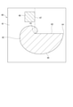
図2において、倍率検査用ワーク40は、透明な平板状ガラス製の基材41を有し、その表面には検査パターン42が形成されている。
検査パターン42は、クロムなどの金属薄膜を基材41の表面に蒸着して形成され、その輪郭の一部は直線状の基準線43とされ、他の部分は螺旋部44とされている。
基準線43は、一端が基準点coで他端が終点ceとされている。
螺旋部44は、基準点coから渦巻き状に拡がりつつ、終点ceまで延びている。
In FIG. 2, the
The
The
The
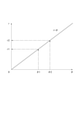
図3にも示すように、螺旋部44は、基準点coを原点(x=0,y=0)とする関数r=θ(係数a=1のアルキメデス螺旋r=aθ)で表される曲線とされている。すなわち、θ=0のとき原点であり、角度θの増加につれて反時計回りに旋回しつつ原点からの距離rが増加する。
図4に示すように、関数r=θにおいては、角度θと距離rとの関係は単純増加となり、角度θと距離rとは一対一の関係にある。すなわち、角度θ1のとき距離r1であり、角度θ2のとき距離r2であり、同様に距離rが定まれば角度θも一意に定まる。
As also shown in FIG. 3, the
As shown in FIG. 4, in the function r = θ, the relationship between the angle θ and the distance r is simply increased, and the angle θ and the distance r have a one-to-one relationship. That is, when the angle θ1 is, the distance is r1, and when the angle is θ2, the distance is r2. Similarly, if the distance r is determined, the angle θ is also uniquely determined.
従って、関数r=θに、基準点coを中心として半径が距離rcの円(検査円45)を重ね合わせると、その交点ccは、基準点coを中心とした基準線43に対する角度θc(=rc)が一意に定まる。
このことから、距離rcの値が未知であっても、半径が距離rcの検査円45を関数r=θに重ね合わせて交点ccの角度θcを検出すれば、関数r=θから距離rcの値を求めることができる。
Therefore, when a circle (inspection circle 45) having a radius of rc centered on the reference point co is superimposed on the function r = θ, the intersection cc is the angle θc (=) with respect to the
From this, even if the value of the distance rc is unknown, if the
図2に戻って、検査パターン42は、光学式測定装置10に検査画像として検出された際に、基準点coが座標系の原点(x=0,y=0)となり、終点ceがx軸線上となる必要がある。このために、倍率検査用ワーク40には、検査パターン42に隣接して補助パターン46が形成されている。
補助パターン46は、検査パターン42と同様に基材41に蒸着して形成されたものであり、輪郭が矩形とされ、その一部である補助線47は、その延長線が基準点coを通る配置とされている。
従って、光学式測定装置10で検査画像を検出する際には、基準線43と補助線47との交点である基準点coを原点とし、基準線43および補助線47がそれぞれx軸およびy軸となるように画像配置を調整することで、適切な配置で検査パターン42の画像を検出することができる。
Returning to FIG. 2, when the
The
Therefore, when the
本実施形態の光学式測定装置10は、前述した図3および図4の原理に基づいて、図2の倍率検査用ワーク40の画像から対物レンズ21の倍率を設定するために、専用の構成が制御装置30に設けられている。
図5において、制御装置30は、検査画像検出部31、画像メモリ32、検査円描画部33、交点検出部34、角度検出部35、距離算出部36、倍率算出部37、装置データ設定値メモリ38および倍率候補選択部39を有する。
The
In FIG. 5, the
検査画像検出部31は、撮像ユニット20で撮像されたワークW(図1参照)の検査画像を検出する。ワークWとして前述した倍率検査用ワーク40を用いることで、その表面の検査パターン42を含む検査画像を検出することができる。
画像メモリ32は、検査画像検出部31で検出した検査画像が記録される。記録された検査画像は、表示装置14に表示することができる。
検査画像検出部31での検査画像の検出の際には、基準点coおよび基準線43の検出を行い、検出した基準点coおよび基準線43の位置を画像メモリ32に記憶しておく。
The inspection
The
When the inspection
検査円描画部33は、画像メモリ32に記録された検査画像(検査パターン42を含む)に対し、検査円45を描画する(図3参照)。
検査円45を描画する際には、ユーザが表示装置14を視認しつつ、制御装置30の操作装置を操作することで、検査円45の半径を設定する。
装置データ設定値メモリ38には、撮像ユニット20で検出される検査画像の画素サイズdpが予め記録されている。検査円描画部33は、検査円45を設定する際に、装置データ設定値メモリ38から画素サイズdpを読み出し、その整数倍の半径が距離r=n×dpの円を、検査円45の候補として表示装置14に表示させる。ユーザは、表示装置14に重ねて表示される検査画像の検査パターン42と検査円45の候補とを比べ、検査画像の螺旋部44と交差する検査円45を選択することで、検査円45を設定することができる。
The inspection
When drawing the
The pixel size dp of the inspection image detected by the
交点検出部34は、画像メモリ32上の検査画像における、螺旋部44と検査円45との交点ccを検出する。
角度検出部35は、画像メモリ32上の検査画像における、基準点coを中心とした交点ccの基準線43に対する角度θcを検出する。
距離算出部36は、検出された角度θcおよび予め設定された関数r=θに基づいて、距離rc=θcを算出する。
倍率算出部37は、算出された距離rc=θc、検査円45に用いた数値n、画素サイズdpから、撮像ユニット20の倍率m=r/rc=(n×dp)/θcを算出する。
The
The
The
The
装置データ設定値メモリ38は、前述した画素サイズdp、関数r=θが記録されるとともに、算出された撮像ユニット20の倍率mを記憶しておくことで、光学式測定装置10が実際のワークW(図1参照)の画像測定を行う際に参照することができる。
撮像ユニット20の倍率は、対物レンズ21の倍率と他の光学要素の倍率との積であり、他の光学要素の倍率を予め測定しておき、撮像ユニット20の倍率mに対して演算することで、対物レンズ21の倍率として算出することができる。
装置データ設定値メモリ38は、このように算出される対物レンズ21の倍率を記憶しておき、光学式測定装置10の画像測定を行う際に参照してもよい。
In the device data setting
The magnification of the
The device data setting
倍率候補選択部39は、検査対象の対物レンズ21として想定される倍率を予め複数登録しておくことで、撮像ユニット20の倍率mから算出された対物レンズ21の未知の倍率に最も近い値を選択し、最終的な対物レンズ21の倍率として設定する。
倍率候補選択部39で登録された倍率m1,m2,m3…は、装置データ設定値メモリ38に記憶しておき、後に倍率候補選択部39で参照することができる。
The magnification
The magnifications m1, m2, m3 ... Registered in the magnification
以上のような制御装置30において、画像メモリ32および装置データ設定値メモリ38は、既存の記憶手段によって実現できる。
また、検査画像検出部31、検査円描画部33、交点検出部34、角度検出部35、距離算出部36および倍率算出部37については、コンピュータシステムで実行されるソフトウェアにより各々の機能を実現することができる。
In the
Further, the functions of the inspection
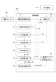
本実施形態の光学式測定装置10において、倍率検査用ワーク40を用いて対物レンズ21の倍率を設定する際の倍率検査手順は以下の通りである。
図6において、ユーザは、先ず光学式測定装置10で使用可能な対物レンズ21の候補倍率を調べ、倍率候補選択部39に登録しておく(処理S1)。
次に、ユーザは、倍率検査用ワーク40を準備し、これを光学式測定装置10のステージ11に装着する(処理S2)。
In the
In FIG. 6, the user first examines the candidate magnification of the
Next, the user prepares the
続いて、ユーザは、撮像ユニット20および制御装置30を動作させ、検査画像検出部31により、検査パターン42を含む倍率検査用ワーク40の検査画像を検出する。
先ず、光学式測定装置10に既知倍率の対物レンズ21を装着し、検査パターン42を含む倍率検査用ワーク40の検査画像を検出する(処理S3)。
既知倍率の対物レンズ21を用いて画像を検出したら、検査パターン42の基準線43と、補助パターン46の補助線47とを検出し、その交点を基準点coとして検出しておく。
Subsequently, the user operates the
First, an
When the image is detected using the
次に、光学式測定装置10に検出対象の対物レンズ21を装着し、検査パターン42を含む倍率検査用ワーク40の検査画像を検出する(処理S4)。
検出対象の対物レンズ21を用いて画像を検出したら、この検査画像に対して、検査円描画部33で検査円45を描画する(処理S5)。
検査画像に検査円45が描画できたら、制御装置30において一連の処理を自動実行させる。すなわち、交点検出部34による交点ccの検出(処理S6)、角度検出部35による交点ccの角度θcの検出(処理S7)、距離算出部36による距離rcの算出(処理S8)、および、倍率算出部37による倍率mの算出(処理S9)が、順次行われる。さらに、倍率mが算出されたら、倍率候補選択部39により、処理1で登録された倍率m1,m2,m3…のなかから何れかが選択され、最終的な対物レンズ21の倍率とされる。
Next, the
After the image is detected using the
When the
以上のような本実施形態によれば、次のような効果が得られる。
本実施形態では、倍率検査用ワーク40を、対物レンズ21の倍率が未知の光学式測定装置10に装着し、撮像ユニット20で倍率検査用ワーク40の表面を撮像することにより、検査パターン42を含む検査画像が取得できる。
検査パターン42において、螺旋部44は、渦巻き状つまり基準点coからの距離rが増加し続ける形状、つまり、螺旋部44上の任意の点の基準線43に対する基準点coを中心とした角度θ、基準点からの距離rとして、0≦θ<2πの範囲でθとrとが一対一で対応する形状である。
従って、螺旋部44に、基準点coを中心とする任意の半径の円(検査円45)を重ね合わせると、互いの交点ccは一点に決まり、基準線43に対する交点ccの、基準点coを中心とした角度θcは一意に決まる。そして、検査パターン42において、交点ccの角度θcが決まれば、検査パターン42上での交点ccから基準点coまでの距離rcも決まる。
とくに、本実施形態では、螺旋部44の曲線が、角度θの関数であるアルキメデス螺旋r=θで与えられており、検査パターン42上の交点ccと基準点coとの距離rc=θcが簡単に得られる。
According to the present embodiment as described above, the following effects can be obtained.
In the present embodiment, the magnifying
In the
Therefore, when a circle (inspection circle 45) having an arbitrary radius centered on the reference point co is superimposed on the
In particular, in the present embodiment, the curve of the
光学式測定装置10においては、対物レンズ21の倍率が未知であっても、撮像ユニット20の画素サイズdpは一定であるため、その整数倍(n倍)の距離r=n×dp(既知)を有する検査円45を描画することができる。
従って、前述した検査パターン42を含む検査画像を取得するとともに、前述した検査円45を取得画像と重ね合わせて描画することで、検査円45における画素の整数倍の長さr=n×dp(測定寸法)と、前述した検査パターン42上の交点ccから基準点coまでの距離rc=θc(実寸法)とが得られ、これらから対物レンズの倍率m=r/rc=(n×dp)/θcを算出することができる。
In the
Therefore, by acquiring the inspection image including the
このような倍率計算は、予めソフトウェアとして組み込んでおくことで、光学式測定装置10に自動処理させることができ、ユーザが倍率検査用ワーク40をセットして処理の開始を指示するだけで、現在の対物レンズ21の倍率を算出することができる。その結果、ユーザによるレンズの倍率設定を正確かつ容易に行うことができる。
Such magnification calculation can be automatically processed by the
本実施形態では、倍率検査用ワーク40として、基材41をガラス板として、検査パターン42は、ガラス板の表面に形成された金属薄膜であるとした。
このため、ガラス表面と薄膜表面との光学的特性の相違により、各々の境界として表れる検査パターン42とくに螺旋部44、および交点ccや基準点coの位置を高精度に検出することができる。さらに、検査パターン42が領域の境界として得られるため、例えば図形が線である場合のような線幅などの影響がなく、精度を高めることができる。
In the present embodiment, the
Therefore, due to the difference in optical characteristics between the glass surface and the thin film surface, the positions of the
検査パターン42に加えて補助パターン46を形成し、基準線43とともに補助線47を検出するようにしたため、検査画像におけるx軸,y軸、原点である基準点coを確実に、かつ正確に検出することができる。
基準点coおよび基準線43の位置を検出する際に、倍率が既知の対物レンズ21を用いるとしたため、検査対象である倍率が未知の対物レンズ21をそのまま基準点coおよび基準線43の位置検出に用いる場合に比べて、これらの位置の検出精度を高めることができる。
Since the
Since the
検査対象の対物レンズ21として想定される倍率m1,m2,m3…を予め複数登録しておき、撮像ユニット20の倍率mから算出された対物レンズ21の未知の倍率に最も近い値を選択し、最終的な対物レンズ21の倍率として設定するようにしたため、撮像ユニット20の倍率mから算出された対物レンズ21の倍率に誤差が多くても(例えば倍率が1.02倍など)、候補として設定しておいた誤差のない倍率(例えば1.00倍など)に揃えることができ、誤差の影響を回避することができる。
A plurality of magnifications m1, m2, m3 ... Assumed to be the
なお、本発明は前述した実施形態に限定されるものではなく、本発明の目的を達成できる範囲での変形などは本発明に含まれる。
前記実施形態では、倍率検査用ワーク40として、ガラス板製の基材41に、金属薄膜製の検査パターン42を形成した。しかし、基材41は他の材質であってもよく、板材に限らずブロックなどであってもよい。また、検査パターン42は、金属薄膜に限らず、他の表面処理あるいは塗装などで形成してもよい。
The present invention is not limited to the above-described embodiment, and modifications to the extent that the object of the present invention can be achieved are included in the present invention.
In the above embodiment, an
前記実施形態では、倍率検査用ワーク40の螺旋部44にアルキメデス螺旋r=aθを用いた。しかし、これに限らず、放物螺旋(r=aθ-2)、双曲螺旋(r=a/θ)およびインボリュート曲線(x=a(cosθ+θsinθ),y=a(sinθ-θcosθ))などであってもよい。つまり、本発明における螺旋部44の条件、つまり、螺旋部44上の任意の点(交点cc)の基準点coを中心とした基準線43に対する角度θ、基準点coからの距離rとしたとき、0≦θ<2πの範囲でθとrとが一対一で対応する形状であればよく、すなわち、r=f(θ)としたとき0≦θ<2πの範囲でf’(θ)が常に正、または常に負の関数であればよい。このような関数に基づく曲線を利用して螺旋部44を容易に形成できるようにすることが望ましい。
In the above embodiment, Archimedes spiral r = aθ is used for the
前記実施形態では、光学式測定装置10において本発明の手順を実行するために、制御装置30に、検査画像検出部31、画像メモリ32、検査円描画部33、交点検出部34、角度検出部35、距離算出部36、倍率算出部37、装置データ設定値メモリ38および倍率候補選択部39を設けた。
しかし、制御装置30の構成は、本実施形態の各部(31~39)に限定されるものではなく、例えば図6の手順が実行できる構成であれば他の構成としてもよい。
In the above embodiment, in order to execute the procedure of the present invention in the
However, the configuration of the
前記実施形態では、検査対象の対物レンズ21の倍率候補を複数登録しておき、算出された倍率に対して近い値を選択するようにしたが、算出された倍率をそのまま検査対象の対物レンズ21の倍率としてもよく、数値を丸める(例えば小数点以下2桁まで等)としてもよい。この場合、図5の倍率候補選択部39は省略し、図6における処理S1および処理S10を省略すればよい。
In the above embodiment, a plurality of magnification candidates of the
前記実施形態では、処理S3で既知倍率の対物レンズ21を用いて検査画像を検出し、これにより基準点coおよび基準線43の位置を検出することで精度を高めるとしたが、検査対象である倍率が未知の対物レンズ21で十分な精度が得られるのであれば、処理S4を省略し、処理S4で検査対象の対物レンズ21で検査画像を検出したのち、この検査画像から基準点coおよび基準線43の位置を検出してもよい。
In the above embodiment, the inspection image is detected by using the
前記実施形態では、検査パターン42に加えて補助パターン46を形成し、基準線43とともに補助線47を検出するようにしたが、検査パターン42に補助線47に沿ったスリットを形成する等により、補助線47(および基準点co)が得られれば、補助パターン46は省略してもよい。
In the above embodiment, the
前記実施形態では、光学式測定装置10としてステージ11、相対移動機構12、撮像ユニット20および制御装置30を有する構成とした。しかし、本発明が適用される光学式測定装置10は他の構成であってもよい。
In the above embodiment, the
本発明は、倍率検査用ワーク、倍率検査方法および光学式測定装置として利用できる。 The present invention can be used as a work for magnification inspection, a magnification inspection method, and an optical measuring device.
10…光学式測定装置、11…ステージ、12…相対移動機構、14…表示装置、20…撮像ユニット、21…対物レンズ、22…CCDカメラ、23…ハーフミラー、24…照明装置、30…制御装置、31…検査画像検出部、32…画像メモリ、33…検査円描画部、34…交点検出部、35…角度検出部、36…距離算出部、37…倍率算出部、38…装置データ設定値メモリ、40…倍率検査用ワーク、41…基材、42…検査パターン、43…基準線、44…螺旋部、45…検査円、46…補助パターン、47…補助線、cc…交点、ce…終点、co…基準点、dp…画素サイズ、m,m1,m2,m3…倍率、n…画素数の数値、r,r1,r2,rc…距離、W…ワーク、θ,θ1,θ2,θc…角度。 10 ... Optical measuring device, 11 ... Stage, 12 ... Relative movement mechanism, 14 ... Display device, 20 ... Imaging unit, 21 ... Objective lens, 22 ... CCD camera, 23 ... Half mirror, 24 ... Lighting device, 30 ... Control Device, 31 ... Inspection image detection unit, 32 ... Image memory, 33 ... Inspection circle drawing unit, 34 ... Intersection detection unit, 35 ... Angle detection unit, 36 ... Distance calculation unit, 37 ... Magnification calculation unit, 38 ... Device data setting Value memory, 40 ... Magnification inspection work, 41 ... base material, 42 ... inspection pattern, 43 ... reference line, 44 ... spiral part, 45 ... inspection circle, 46 ... auxiliary pattern, 47 ... auxiliary line, cc ... intersection, ce ... end point, co ... reference point, dp ... pixel size, m, m1, m2, m3 ... magnification, n ... numerical value of number of pixels, r, r1, r2, rc ... distance, W ... work, θ, θ1, θ2, θc ... Angle.
Claims (5)
表面に検査パターンが形成された基材を有し、
前記検査パターンは、基準点を通る直線状の基準線と、前記基準点から渦巻き状に延びる螺旋部とを有することを特徴とする倍率検査用ワーク。 It is a work for magnification inspection for calculating the magnification of the objective lens of the optical measuring device from the inspection image obtained by detecting the image by the optical measuring device.
It has a base material with an inspection pattern formed on the surface,
The inspection pattern is a work for magnification inspection characterized by having a linear reference line passing through a reference point and a spiral portion spirally extending from the reference point.
前記螺旋部は、アルキメデス螺旋、放物螺旋、双曲螺旋およびインボリュート曲線のいずれかであることを特徴とする倍率検査用ワーク。 In the work for magnification inspection according to claim 1,
The work for magnification inspection, wherein the spiral portion is any one of an Archimedes spiral, a parabolic spiral, a bicurved spiral, and an involute curve.
前記基材はガラス板であり、前記検査パターンは、前記ガラス板の表面に形成された金属薄膜であることを特徴とする倍率検査用ワーク。 In the work for magnification inspection according to claim 1 or 2.
A work for magnification inspection, wherein the base material is a glass plate, and the inspection pattern is a metal thin film formed on the surface of the glass plate.
表面に検査パターンが形成された基材を有し、前記検査パターンは、基準点を通る直線状の基準線と、前記基準点から渦巻き状に延びる螺旋部とを有する倍率検査用ワークを準備しておき、
前記光学式測定装置に前記倍率検査用ワークを装着し、
前記光学式測定装置で前記検査パターンを含む検査画像を検出し、
検出した前記検査画像に、前記基準点を中心として半径が整数個の画素分の検査円を描画し、
前記検査画像で、前記検査円と前記螺旋部との交点を検出し、
前記交点の前記基準点を中心とした前記基準線に対する角度を検出し、
検出した前記角度から、前記検査パターンでの前記交点と前記基準点との距離を算出し、
算出した前記距離、前記検査円の半径の画素数および前記光学式測定装置の画素サイズから前記対物レンズの倍率を算出する、ことを特徴とする倍率検査方法。 This is a method for inspecting the magnification of the objective lens of an optical measuring device.
A work piece for magnification inspection having a base material having an inspection pattern formed on the surface thereof, and the inspection pattern having a linear reference line passing through the reference point and a spiral portion spirally extending from the reference point is prepared. Aside,
The work for magnification inspection is attached to the optical measuring device, and the work is attached.
The inspection image including the inspection pattern is detected by the optical measuring device, and the inspection image is detected.
An inspection circle for pixels having an integer radius centered on the reference point is drawn on the detected inspection image.
In the inspection image, the intersection of the inspection circle and the spiral portion is detected.
The angle of the intersection with respect to the reference line centered on the reference point is detected.
From the detected angle, the distance between the intersection and the reference point in the inspection pattern is calculated.
A magnification inspection method comprising calculating the magnification of the objective lens from the calculated distance, the number of pixels of the radius of the inspection circle, and the pixel size of the optical measuring device.
前記制御装置は、
装着された前記検査パターンを含む前記倍率検査用ワークの検査画像を検出する検査画像検出部と、
検出した前記検査画像に、前記基準点を中心として半径が整数個の画素分の検査円を描画する検査円描画部と、
前記検査画像で、前記検査円と前記螺旋部との交点を検出する交点検出部と、
前記交点の前記基準点を中心とした前記基準線に対する角度を検出する角度検出部と、
検出した前記角度から、前記検査パターンでの前記交点と前記基準点との距離を算出する距離算出部と、
算出した前記距離、前記検査円の半径の画素数および前記光学式測定装置の画素サイズから前記対物レンズの倍率を算出する倍率算出部と、を有することを特徴とする光学式測定装置。 It has an image pickup device that images a work through an objective lens and a control device that controls the image pickup device, and has a linear reference line that passes through a reference point as an inspection pattern and a spiral portion that extends spirally from the reference point. It is an optical measuring device to which the formed work for magnification inspection can be attached.
The control device is
An inspection image detection unit that detects an inspection image of the work for magnification inspection including the attached inspection pattern, and an inspection image detection unit.
An inspection circle drawing unit that draws an inspection circle for pixels having an integer radius around the reference point on the detected inspection image.
In the inspection image, an intersection detection unit that detects the intersection of the inspection circle and the spiral portion, and
An angle detection unit that detects an angle of the intersection with respect to the reference line centered on the reference point,
A distance calculation unit that calculates the distance between the intersection and the reference point in the inspection pattern from the detected angle.
An optical measuring device comprising: a magnification calculating unit for calculating the magnification of the objective lens from the calculated distance, the number of pixels of the radius of the inspection circle, and the pixel size of the optical measuring device.
Priority Applications (1)
| Application Number | Priority Date | Filing Date | Title |
|---|---|---|---|
| JP2017230204A JP6991843B2 (en) | 2017-11-30 | 2017-11-30 | Magnification inspection workpiece, magnification inspection method and optical measuring device |
Applications Claiming Priority (1)
| Application Number | Priority Date | Filing Date | Title |
|---|---|---|---|
| JP2017230204A JP6991843B2 (en) | 2017-11-30 | 2017-11-30 | Magnification inspection workpiece, magnification inspection method and optical measuring device |
Publications (2)
| Publication Number | Publication Date |
|---|---|
| JP2019100795A JP2019100795A (en) | 2019-06-24 |
| JP6991843B2 true JP6991843B2 (en) | 2022-01-13 |
Family
ID=66976781
Family Applications (1)
| Application Number | Title | Priority Date | Filing Date |
|---|---|---|---|
| JP2017230204A Active JP6991843B2 (en) | 2017-11-30 | 2017-11-30 | Magnification inspection workpiece, magnification inspection method and optical measuring device |
Country Status (1)
| Country | Link |
|---|---|
| JP (1) | JP6991843B2 (en) |
Families Citing this family (1)
| Publication number | Priority date | Publication date | Assignee | Title |
|---|---|---|---|---|
| CN120558100B (en) * | 2025-07-29 | 2025-09-30 | 涌淳半导体(无锡)有限公司 | Optical film thickness measuring device with anti-interference function |
Citations (2)
| Publication number | Priority date | Publication date | Assignee | Title |
|---|---|---|---|---|
| JP2012002664A (en) | 2010-06-17 | 2012-01-05 | Mitsutoyo Corp | Calibration pattern for image apparatus |
| JP2016125917A (en) | 2015-01-05 | 2016-07-11 | 日本電信電話株式会社 | Three-dimensional shape measurement device, method and program |
Family Cites Families (3)
| Publication number | Priority date | Publication date | Assignee | Title |
|---|---|---|---|---|
| JP3409931B2 (en) * | 1994-12-19 | 2003-05-26 | 株式会社ニコン | Magnification calibration plate for image processing measurement machine |
| JP2001041710A (en) * | 1999-07-28 | 2001-02-16 | Mitsutoyo Corp | Lens magnification recognition method and optical measuring system of optical measuring device |
| JP2008112417A (en) * | 2006-10-31 | 2008-05-15 | Dkk Toa Corp | Measurement management system and remote management system |
-
2017
- 2017-11-30 JP JP2017230204A patent/JP6991843B2/en active Active
Patent Citations (2)
| Publication number | Priority date | Publication date | Assignee | Title |
|---|---|---|---|---|
| JP2012002664A (en) | 2010-06-17 | 2012-01-05 | Mitsutoyo Corp | Calibration pattern for image apparatus |
| JP2016125917A (en) | 2015-01-05 | 2016-07-11 | 日本電信電話株式会社 | Three-dimensional shape measurement device, method and program |
Also Published As
| Publication number | Publication date |
|---|---|
| JP2019100795A (en) | 2019-06-24 |
Similar Documents
| Publication | Publication Date | Title |
|---|---|---|
| JP5997989B2 (en) | Image measuring apparatus, control method thereof, and program for image measuring apparatus | |
| US10958843B2 (en) | Multi-camera system for simultaneous registration and zoomed imagery | |
| CN109951632B (en) | Variable focus lens system including a focus state reference subsystem | |
| EP3839599B1 (en) | Metrology system with transparent workpiece surface mode | |
| JP6713185B2 (en) | Inspection apparatus and inspection method using template matching | |
| CN101762232B (en) | Multi-surface focusing system and method | |
| US9471984B2 (en) | Method for self-calibration of a microscope apparatus | |
| US12553827B2 (en) | Method and apparatus for determining crystallographic orientation on crystalline surfaces | |
| JP5467962B2 (en) | Measurement setting data creation device, measurement setting data creation method, program for measurement setting data creation device, and dimension measurement device | |
| JP2014085115A (en) | Dimension measurement device, dimension measurement method, and program for dimension measurement device | |
| CN117470836A (en) | Computer-implemented method, measuring device and computer program product | |
| US10827114B2 (en) | Imaging system and setting device | |
| JP2013170831A (en) | Strain measuring device and strain measuring method | |
| JP2012037257A (en) | Measurement setting data creation device, measurement setting data creation method, and program for measurement setting data creation device | |
| JP6991843B2 (en) | Magnification inspection workpiece, magnification inspection method and optical measuring device | |
| JP5191265B2 (en) | Optical microscope apparatus and data processing apparatus for optical microscope | |
| WO2020110711A1 (en) | Inspection system, inspection method, and program | |
| US12190543B2 (en) | Lens calibration method for digital imaging apparatus | |
| JP2024086618A (en) | Machine vision system using measuring and marking device | |
| CN119604888A (en) | Computer-implemented method, method, measuring device and computer program product | |
| TWI699756B (en) | Positioning and measuring system based on flexible feature image scale | |
| KR20100034039A (en) | Micro-dimension measuring method and measuring device | |
| JP2004198293A (en) | Vickers hardness tester | |
| JP2006003276A (en) | Three dimensional geometry measurement system | |
| Bossemeyer et al. | Calibration of focus-adjustable cameras for triangulation sensors by model-based camera parameter estimation: Polynomial estimation of the calibration parameters over the focal range of an objective lens |
Legal Events
| Date | Code | Title | Description |
|---|---|---|---|
| A621 | Written request for application examination |
Free format text: JAPANESE INTERMEDIATE CODE: A621 Effective date: 20201006 |
|
| A977 | Report on retrieval |
Free format text: JAPANESE INTERMEDIATE CODE: A971007 Effective date: 20210811 |
|
| A131 | Notification of reasons for refusal |
Free format text: JAPANESE INTERMEDIATE CODE: A131 Effective date: 20210824 |
|
| A521 | Request for written amendment filed |
Free format text: JAPANESE INTERMEDIATE CODE: A523 Effective date: 20210927 |
|
| TRDD | Decision of grant or rejection written | ||
| A01 | Written decision to grant a patent or to grant a registration (utility model) |
Free format text: JAPANESE INTERMEDIATE CODE: A01 Effective date: 20211109 |
|
| A61 | First payment of annual fees (during grant procedure) |
Free format text: JAPANESE INTERMEDIATE CODE: A61 Effective date: 20211208 |
|
| R150 | Certificate of patent or registration of utility model |
Ref document number: 6991843 Country of ref document: JP Free format text: JAPANESE INTERMEDIATE CODE: R150 |
|
| R250 | Receipt of annual fees |
Free format text: JAPANESE INTERMEDIATE CODE: R250 |