JP6991542B2 - Injection system - Google Patents
Injection system Download PDFInfo
- Publication number
- JP6991542B2 JP6991542B2 JP2017056053A JP2017056053A JP6991542B2 JP 6991542 B2 JP6991542 B2 JP 6991542B2 JP 2017056053 A JP2017056053 A JP 2017056053A JP 2017056053 A JP2017056053 A JP 2017056053A JP 6991542 B2 JP6991542 B2 JP 6991542B2
- Authority
- JP
- Japan
- Prior art keywords
- substance
- injection
- pressurizing
- liquid state
- accommodating portion
- Prior art date
- Legal status (The legal status is an assumption and is not a legal conclusion. Google has not performed a legal analysis and makes no representation as to the accuracy of the status listed.)
- Active
Links
Images


Description
特許法第30条第2項適用 中条俊大,外3名,“小型衛星向けの気液平衡調圧系の開発について”,第59回宇宙科学技術連合講演会講演集,一般社団法人日本航空宇宙学会,2015年10月7日,2B04 Application of
特許法第30条第2項適用 2015年10月8日一般社団法人日本航空宇宙学会主催の第59回宇宙科学技術連合講演会で発表Application of
本発明は噴射システムに関する。特に本発明は、気液平衡調圧系を用いた一液、二液、又は三液以上の液体燃料推進システムに用いることができる噴射システムに関する。 The present invention relates to an injection system. In particular, the present invention relates to an injection system that can be used in a one-component, two-component, or three-component or more liquid fuel propulsion system using a vapor-liquid equilibrium pressure-regulating system.
液体燃料を用いた推進システムとしては、一液推進システムや二液推進システムが知られている。一液推進システムとしては、ヒドラジン(N2H4)を液体燃料とし、これをイリジウム含有触媒に触れさせることで高温の噴射ガスを発生させて推力を得る方式や、過酸化水素を液体燃料とする方式等が知られており、二液推進システム(ブローダウン方式、調圧方式)としては、ヒドラジンを液体燃料とし、四酸化二窒素を酸化剤とし、これらを混合、燃焼させて噴射ガスを発生させる方式や、液体水素を燃料とし、液体酸素を酸化剤とする方式等が知られている。 As a propulsion system using liquid fuel, a one-component propulsion system and a two-component propulsion system are known. As a one-liquid propulsion system, hydrazine (N 2 H 4 ) is used as a liquid fuel, and this is brought into contact with an iridium-containing catalyst to generate a high-temperature injection gas to obtain thrust, and hydrogen peroxide is used as a liquid fuel. As a two-component propulsion system (blowdown method, pressure regulation method), hydrazine is used as a liquid fuel, dinitrogen tetraoxide is used as an oxidizing agent, and these are mixed and burned to generate an injection gas. A method of generating the fuel and a method of using liquid hydrogen as a fuel and liquid oxygen as an oxidizing agent are known.
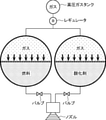
二液推進システムにおいては、高性能化のために高圧ガスによる調圧機構を設けることがある(調圧方式。後述の図2B参照)。この方式では、高圧ガスタンクに収容された高圧の不活性ガスを、レギュレータを介して液体燃料タンク、酸化剤タンクに供給することで両タンク内の圧力を調整する。しかし、このような方式の推進システムは高圧ガス系を含むシステムとなるためガスや液体がリークするリスクがあり、システム全体として質量も増加する等の課題がある。 In a two-component propulsion system, a pressure regulating mechanism using a high-pressure gas may be provided for high performance (pressure regulating method, see FIG. 2B described later). In this method, the pressure in both tanks is adjusted by supplying the high-pressure inert gas contained in the high-pressure gas tank to the liquid fuel tank and the oxidant tank via a regulator. However, since such a propulsion system includes a high-pressure gas system, there is a risk of gas or liquid leaking, and there is a problem that the mass of the system as a whole increases.
また、図2Bの例のように、二液(液体燃料、酸化剤)系を共通の配管系統で調圧すると、二液が高圧ガスタンク側に逆流して混合する可能性がある。金星探査機「あかつき」の金星軌道投入失敗や火星探査機「マーズ・オブザーバー」の爆発は、そのような原因により発生したと考えられる。 Further, if the pressure of the two liquids (liquid fuel, oxidant) system is adjusted by a common piping system as in the example of FIG. 2B, the two liquids may flow back to the high pressure gas tank side and be mixed. It is probable that the failure to insert the Venus orbit of the Venus probe "Akatsuki" and the explosion of the Mars probe "Mars Observer" were caused by such causes.
これに関し、小惑星探査機「はやぶさ2」の二液推進システムでは、二液の調圧機構を完全分離することにより二液の混合を防止している。しかしながら、このような構成によりシステム全体の質量は更に増加し、リークのリスクも高まった。また、二液を別個に圧力制御するため圧力がアンバランスとなり異常噴射を起こす可能性もある。 In this regard, the two-component propulsion system of the asteroid explorer "Hayabusa 2" prevents the two-component mixing by completely separating the two-component pressure regulation mechanism. However, such a configuration further increases the mass of the entire system and increases the risk of leakage. In addition, since the pressure of the two liquids is controlled separately, the pressure may become unbalanced and abnormal injection may occur.
以上に鑑み本発明は、高圧ガス系を用いずに調圧可能な噴射システムを提供することを課題とする。 In view of the above, it is an object of the present invention to provide an injection system capable of adjusting the pressure without using a high pressure gas system.
上記の課題を解決すべく、本発明に係る噴射システムは、噴射用物質と加圧用物質とを収容する収容部と、前記収容部に収容された前記噴射用物質から噴射流を生成する噴射流生成部と、前記噴射流生成部で生成された噴射流を噴射する噴射口とを備え、前記加圧用物質は、少なくとも一部が前記収容部内で気化することにより前記収容部内を加圧する。 In order to solve the above problems, in the injection system according to the present invention, a jet flow for accommodating an injection substance and a pressurizing substance and a jet flow for generating a jet flow from the injection substance accommodated in the accommodating portion. It is provided with a generation unit and an injection port for injecting a jet flow generated by the jet flow generation unit, and at least a part of the pressurizing substance is vaporized in the accommodation unit to pressurize the inside of the accommodation unit.
上記噴射システムは、さらに、前記収容部内に設けられ、前記噴射用物質と前記加圧用物質とを分離し、前記噴射用物質に、前記加圧用物質による加圧を伝達する分離部材を有する。 The injection system further includes a separating member provided in the accommodating portion, which separates the injection substance and the pressurizing substance, and transmits the pressurization by the pressurizing substance to the injection substance.
前記噴射用物質の熱容量は前記加圧用物質の熱容量よりも大きい。 The heat capacity of the injection substance is larger than the heat capacity of the pressurizing substance.
前記収容部は、前記収容部を加圧する第2の加圧用物質を収容する。 The accommodating portion accommodates a second pressurizing substance that pressurizes the accommodating portion.
上記噴射システムは、さらに、前記収容部内の温度を制御して、前記加圧用物質を気化する温度制御部を有する。 The injection system further includes a temperature control unit that controls the temperature inside the accommodation unit to vaporize the pressurizing substance.
上記の課題を解決すべく、本発明に係る噴射システムは、第1の噴射用物質と第1の加圧用物質とを収容する第1の収容部と、第2の噴射用物質と第2の加圧用物質とを収容する第2の収容部と、前記第1の収容部に収容された前記第1の噴射物質及び前記第2の収容部に収容された前記第2の噴射物質とから噴射流を生成する噴射流生成部と、前記噴射流生成部で生成された噴射流を噴射する噴射口とを備え、前記第1及び第2の噴射用物質は、それぞれ前記第1及び第2の収容部内で少なくとも一部が気化することにより前記第1及び第2の収容部内を加圧する。 In order to solve the above problems, the injection system according to the present invention has a first accommodating portion for accommodating a first injection substance and a first pressurizing substance, a second injection substance, and a second. Injection from the second accommodating portion accommodating the pressurizing material, the first propellant material accommodated in the first accommodating portion, and the second propellant material accommodated in the second accommodating portion. The first and second injection materials are the first and second injection materials, respectively, provided with an injection flow generation unit that generates a flow and an injection port that injects the injection flow generated by the injection flow generation unit. Pressurization is performed in the first and second accommodating portions by vaporizing at least a part of the accommodating portion.
前記第1の噴射用物質は燃料であり、前記第2の噴射用物質は酸化剤であり、前記噴射流生成部は、該燃料と該酸化剤とを混合することにより該燃料を燃焼させて前記噴射流を生成する。 The first injection substance is a fuel, the second injection substance is an oxidant, and the jet flow generator burns the fuel by mixing the fuel and the oxidant. Generate the jet flow.
本発明に係る噴射システムは、さらに、前記第1の収容部内に設けられ、前記第1の噴射用物質と前記第1の加圧用物質とを分離し、前記第1の噴射用物質に前記第1の加圧用物質による加圧を伝達する第1の分離部材と、前記第2の収容部内に設けられ、前記第2の噴射用物質と前記第2の加圧用物質とを分離し、前記第2の噴射用物質に前記第2の加圧用物質による加圧を伝達する第2の分離部材と、を有する。
The injection system according to the present invention is further provided in the first accommodating portion, separates the first injection substance and the first pressurizing substance, and is used as the first injection substance. The first separating member for transmitting the pressurization by the pressurizing
前記第1の噴射用物質の熱容量は前記第1の加圧用物質の熱容量よりも大きく、前記第2の噴射用物質の熱容量は前記第2の加圧用物質の熱容量よりも大きい。 The heat capacity of the first injection substance is larger than the heat capacity of the first pressurizing substance, and the heat capacity of the second injection substance is larger than the heat capacity of the second pressurizing substance.
前記第1の収容部は、前記第1の収容部を加圧する第3の加圧用物質を収容し、前記第2の収容部は、前記第2の収容部を加圧する第4の加圧用物質を収容する。 The first accommodating portion accommodates a third pressurizing substance that pressurizes the first accommodating portion, and the second accommodating portion is a fourth pressurizing substance that pressurizes the second accommodating portion. To accommodate.
本発明に係る噴射システムは、さらに、前記第1の収容部内の温度を制御して、前記第1の加圧用物質を気化する第1の温度制御部と、前記第2の収容部内の温度を制御して前記第2の加圧用物質を気化する第2の温度制御部とを有する。 The injection system according to the present invention further controls the temperature in the first accommodating portion to control the temperature in the first accommodating portion and the first temperature control unit for vaporizing the first pressurizing substance. It has a second temperature control unit that controls and vaporizes the second pressurizing substance.
本発明に係る噴射システムは、第kの噴射用物質と第kの加圧用物質とを収容する第kの収容部として、1からn(nは2以上の整数)までの整数kに対してそれぞれ与えられる第1から第nの収容部と、前記第1から第nの収容部にそれぞれ収容された前記第1から第nの噴射用物質から噴射流を生成する噴射流生成部と、前記噴射流生成部で生成された噴射流を噴射する噴射口とを備え、前記第1から第nの加圧用物質は、少なくとも一部が前記第1から第nの収容部内でそれぞれ気化することにより、前記第1から第nの収容部内を加圧する。 In the injection system according to the present invention, as a storage unit for k, which accommodates the kth jetting substance and the kth pressurizing substance, for an integer k from 1 to n (n is an integer of 2 or more). A jet flow generating unit that generates a jet flow from the first to nth accommodating portions, the first to nth accommodating portions accommodated in the first to nth accommodating portions, respectively, and the jet flow generating unit. It is provided with an injection port for injecting a jet flow generated by a jet flow generation unit, and at least a part of the first to nth pressurizing substances is vaporized in the first to nth accommodation units. , The inside of the first to nth accommodating portions is pressurized.
本発明によれば、噴射システムにおいて、高圧ガスタンク等、別個の高圧ガス系を用いず加圧用物質の気化による調圧が可能となるため、リークの可能性を低減し、また噴射システムの軽量化も可能となる。 According to the present invention, in the injection system, the pressure can be adjusted by vaporizing the pressurizing substance without using a separate high-pressure gas system such as a high-pressure gas tank, so that the possibility of leakage is reduced and the weight of the injection system is reduced. Is also possible.
これより図面を用いて、本発明に係る噴射システムの実施形態を説明する。ただし、本発明に係る噴射システムは、各図面、及び関連する説明により示される特定の具体的構成へと限定されるわけではなく、本発明の範囲内で適宜変更可能である。例えば、加圧用物質として以下の実施例では液化ガスを用いるが、加圧用物質として固体から気体へと昇華する物質を用い、当該昇華によって収容部内の圧力を回復させる等の形態でも本発明の噴射システムを実施できる。また複数の収容部を備える態様において、第1,第2,及びそれ以降の加圧用物質は、一部又は全てが同一であっても、全て異なる物質であってもよい。追加の加圧ガスを用いる場合も、用いるガスは加圧用物質との反応性が低ければ任意であるし、複数の収容部を備える態様において複数の収容部内で追加の加圧ガスを用いる場合、第1,第2,及びそれ以降の加圧ガスは、一部又は全てが同一であっても、全て異なるガスであってもよい。また以下の実施例において噴射システムは推進器用の噴射システムとして説明されるが、本発明の噴射システムをそれ以外の用途に用いることも可能である。 From this, an embodiment of the injection system according to the present invention will be described with reference to the drawings. However, the injection system according to the present invention is not limited to the specific specific configuration shown by each drawing and the related description, and can be appropriately changed within the scope of the present invention. For example, the liquefied gas is used as the pressurizing substance in the following examples, but the injection of the present invention can also be performed by using a substance that sublimates from a solid to a gas as the pressurizing substance and recovering the pressure in the accommodating portion by the sublimation. The system can be implemented. Further, in the embodiment including a plurality of accommodating portions, the first, second, and subsequent pressurizing substances may be partially or all the same, or may be all different substances. Even when an additional pressurized gas is used, the gas to be used is arbitrary as long as the reactivity with the pressurizing substance is low, and when the additional pressurized gas is used in the plurality of accommodating portions in the embodiment including the plurality of accommodating portions, the additional pressurized gas is used. The first, second, and subsequent pressurized gases may be partially or wholly the same, or may be all different gases. Further, although the injection system is described as an injection system for a propulsion device in the following examples, the injection system of the present invention can be used for other purposes.
気液平衡調圧系の概念
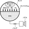
本発明により、典型的には小型宇宙機向けの推進系に用いる新しい調圧系として、気液平衡調圧系が提案される。一液式、二液式の気液平衡調圧系の概念図を図1,図2Aにそれぞれ示す。また図2Bに、高圧ガス系を用いた従来の調圧系の概念図を示す。
Concept of Vapor-Liquid Equilibrium Pressure Control System The present invention proposes a gas-liquid equilibrium pressure control system as a new pressure control system typically used for a propulsion system for small spacecraft. Conceptual diagrams of a one-component type and a two-component type vapor-liquid equilibrium pressure regulation system are shown in FIGS. 1 and 2A, respectively. Further, FIG. 2B shows a conceptual diagram of a conventional pressure regulating system using a high-pressure gas system.
気液平衡調圧系においては、タンク内に収容された(液体)燃料又は(液体)酸化剤(二液式の場合)を押圧するための「押しガス」として、液化ガスを用いる。タンク内は圧力変形可能なダイヤフラムで仕切られており、液化ガス側の領域と燃料又は酸化剤側の領域との間で、ダイヤフラムを介して圧力が伝達される。 In the gas-liquid equilibrium pressure control system, a liquefied gas is used as a "pushing gas" for pressing the (liquid) fuel or the (liquid) oxidant (in the case of a two-component type) contained in the tank. The inside of the tank is partitioned by a pressure-deformable diaphragm, and pressure is transmitted via the diaphragm between the region on the liquefied gas side and the region on the fuel or oxidizer side.
推力発生動作のために燃料や酸化剤がタンクから放出されることで一時的にタンク内の圧力が低下しても、液体状態の液化ガスが蒸発することにより、タンク内の圧力は液化ガスの蒸気圧へと調圧される。すなわち、燃料、酸化剤の残量によらず、タンク内が気液平衡状態に保たれ、圧力が液化ガスの飽和蒸気圧で一定となる(圧力低下が大きい場合や持続的な噴射の場合であっても、少なくとも部分的には圧力が回復する。)。これにより、推進器の反応室(燃焼室)に燃料や酸化剤を安定供給することができる。 Even if the pressure inside the tank temporarily drops due to the release of fuel and oxidizing agent from the tank due to the thrust generation operation, the pressure inside the tank will be the same as that of the liquefied gas due to the evaporation of the liquefied gas in the liquid state. The pressure is adjusted to the vapor pressure. That is, regardless of the remaining amount of fuel and oxidant, the inside of the tank is maintained in a gas-liquid equilibrium state, and the pressure becomes constant with the saturated vapor pressure of the liquefied gas (when the pressure drop is large or when continuous injection is performed). Even so, the pressure will recover, at least in part.) As a result, fuel and oxidizer can be stably supplied to the reaction chamber (combustion chamber) of the propeller.
従来の高圧ガスタンクを用いた調圧系と比較し、気液平衡調圧系は以下の点で有利である。
1.高圧ガスタンクとレギュレータを使わないため、システム全体が軽量となる。
2.高圧ガス系がない(システム全体で液化ガスの蒸気圧が最高圧力となる)ため、リークの可能性を低減できる。
3.(二液式の場合)燃料タンクと酸化剤タンクが直接接続されていないため、燃料と酸化剤が想定外の場所(タンクよりも上流の配管内等)で混合してしまうリスクがない。
4.(二液式の場合)燃料と酸化剤の混合比O/Fを液化ガスの温度制御によって制御することができる。
Compared with the conventional pressure control system using a high pressure gas tank, the gas-liquid equilibrium pressure control system is advantageous in the following points.
1. 1. Since no high pressure gas tank and regulator are used, the entire system is lightweight.
2. 2. Since there is no high-pressure gas system (the vapor pressure of the liquefied gas is the maximum pressure in the entire system), the possibility of leakage can be reduced.
3. 3. (In the case of the two-component type) Since the fuel tank and the oxidizer tank are not directly connected, there is no risk that the fuel and the oxidizer will be mixed in an unexpected place (in the piping upstream of the tank, etc.).
4. (In the case of the two-component type) The mixing ratio O / F of the fuel and the oxidant can be controlled by controlling the temperature of the liquefied gas.
なお、タンク内の液化ガスの充填量を減らし、代わりに窒素ガス等の追加の押しガスを加えることにより、ハイブリッドシステムとして気液平衡調圧系を構成することも可能である。図1は、一液式の気液平衡調圧系に窒素ガスN2を追加した構成を示しているが、二液式以上の場合でも同様に追加の押しガスを加えることができる。この場合、タンク内の圧力は一定ではなくなるが、システムを更に軽量化することが可能となり、タンク内の全圧を大きくできる。さらに、測定されたタンク内の圧力によって、燃料や酸化剤の残量を推定することも可能となる。 It is also possible to configure a gas-liquid equilibrium pressure regulation system as a hybrid system by reducing the filling amount of the liquefied gas in the tank and adding an additional pushing gas such as nitrogen gas instead. FIG. 1 shows a configuration in which nitrogen gas N 2 is added to a one-component vapor-liquid equilibrium pressure regulation system, but an additional push gas can be similarly added even in the case of a two-component system or more. In this case, the pressure in the tank is not constant, but the system can be further reduced in weight and the total pressure in the tank can be increased. Furthermore, it is possible to estimate the remaining amount of fuel or oxidizer from the measured pressure in the tank.
噴射システムの構成
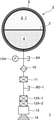
図3Aは、本発明の第1実施形態に係る、小型宇宙機用推進システムに利用可能な一液式噴射システム1(推進器)のシステム・ダイアグラム図を示す。噴射システム1は、収容容器2と、注排弁9Aと、フィルタ10と、ラッチ式電磁弁11と、テストポート9D-1と、圧力センサ15Aと、推薬弁12A-1,12A-2と、反応室13と、噴射口14とを備えている。
Configuration diagram 3A of the injection system shows a system diagram of a one-component injection system 1 (propellant) that can be used in a propulsion system for a small spacecraft according to the first embodiment of the present invention. The
各種の弁、フィルタ、配管系統等の構成は、特開2015-214956号の図1等に記載されたものと概ね同様である。すなわち、注排弁9Aにより液体燃料を収容容器2に注入、又は収容容器2から排出し、フィルタ10によって、収容容器2から放出された液体燃料中の不純物を除去し、ラッチ式電磁弁11、推薬弁12A-1,12A-2の開閉により、不純物が除去された液体燃料の反応室13側への通過を制御する。
The configurations of various valves, filters, piping systems, etc. are substantially the same as those described in FIG. 1 and the like of Japanese Patent Application Laid-Open No. 2015-214956. That is, the liquid fuel is injected into or discharged from the
なお、本実施の形態における収容容器2は、収容部に該当し、ラッチ式電磁弁11及び推薬弁12A-1、12A-2は噴射物質供給部に該当し、反応室13は噴射流生成部に該当する。
The
反応室13においては、液体燃料に触媒(液体燃料としてヒドラジンを用いる場合、イリジウム含有触媒等)を作用させて噴射ガスを生成し、噴射ガスを噴射口14から噴射することで推力を発生させる。
In the
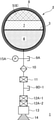
収容容器2は特許文献2と同様にSUS(ステンレス鋼)等からなる。収容容器2内は、ゴム等、圧力変形可能な材質からなる分離部材であるダイヤフラム3で仕切られており、一方の領域には噴射用物質であるヒドラジン(N2H4)等の液体燃料4が収容され、他方の領域には、加圧用物質である代替フロンガスHFC-218(C3F8)等の液化ガスが収容されている。なお、収容容器2の液化ガス側の領域には液体状態の液化ガス6と気体状態の液化ガス7が収容されるが、これらは図3Aに示すとおり混在して収容されていてもよいし、あるいは図3Bに変形例として示すとおり、加圧用物質を保持する加圧用物質保持部として機能する発泡金属5によって液体状態の液化ガス6を保持してもよい。図3Bの構成において、収容容器2の液化ガス側領域の内壁には、特許文献2と同様に、例えば空隙率95%程度の銅製、SUS製等の発泡金属5が、接着剤を用いて取り付けられており、液体状態の液化ガス6は発泡金属5の気孔間に形成される気液界面の表面張力によって保持されている(特許文献2中、[0004]、及び特許文献1)。気体状態の液化ガス7は、図3Bに示すとおり液化ガス側の空間領域に収容されている。
The
液化ガス側の領域においては液体状態の液化ガス6にかかる重力よりも気体状態の液化ガス7の蒸気圧が支配的であり、発泡金属5によって液体状態の液化ガス6を保持することは必須ではないが、保持することにより噴射システム1の姿勢制御が安定化し、またヒータ8から液化ガスへの熱伝導が速やかに起こると考えられる。一方で、発泡金属5を用いることで噴射システム1の重量が増加するため、システム軽量化のためには図3Aに示す構成を用いることが好ましい。発泡金属を用いる構成、用いない構成のいずれにおいても本発明の噴射システムを実施可能である(図4以降に示す変形例や、図6以降に示す二液式、三液式以上の噴射システムにおいても同様)。
In the region on the liquefied gas side, the vapor pressure of the liquefied
また収容容器2の外壁には、図示しない温度センサで検知した収容容器2内の温度に基づいて、収容容器2内の温度が液体状態の液化ガス6が気化するように温度制御するヒータ8が全周にわたって取り付けられている。
Further, on the outer wall of the
なお、図3A,図3B中、各構成要素を結ぶ線分は特許文献2と同様に配管を表わす。圧力センサ15Aやテストポート9D-1も特許文献2の構成に含まれるものと同様であり、圧力センサ15Aによって配管内の圧力を監視するとともに、推薬弁12A-1,12A-2を閉じた状態でテストポート9D-1を開いてヘリウムガス等を注入し、リークがないかの確認を行う。
In FIGS. 3A and 3B, the line segment connecting each component represents a pipe as in
噴射システムの動作
以下、噴射システム1の動作を説明する。ここで、特許文献2と同様に、各電磁弁の開閉やヒータ、各種センサ等の動作制御は、任意の制御回路(不図示)を介して遠隔操作等により行われることとし、各注排弁からの注液(注気)・排液(排気)は、典型的には操作者により行われることとするが、これらの制御・動作を行う具体的手段は実施態様に応じて適宜変更可能である。なお、収容容器2内の液化ガス側領域には、予め上述のとおり液化ガス6(液体),7(気体)が収容されているものとする(液化ガスを注入するための注排弁等は不図示)。
Operation of the injection system The operation of the
噴射システム1の動作準備として、まず注排弁9Aから収容容器2の液体燃料側領域に液体燃料4を注入する。収容容器2の液化ガス側領域は液化ガスの気液平衡状態となっており、液化ガスの蒸気圧によりダイヤフラム3が押圧される。押圧でダイヤフラム3が変形することにより、液体燃料4にも圧力がかかる。この状態でラッチ式電磁弁11を開き、更に推薬弁12A-1,12A-2を開くと、液化ガスの蒸気圧により収容容器2から放出され、フィルタ10で不純物除去された液体燃料4が反応室13へと供給され、反応室13内で液体燃料4が触媒の作用を受けることにより噴射ガスが発生する。噴射口14から噴射ガスが噴射されることにより推力が発生する。
In preparation for the operation of the
収容容器2から液体燃料4が放出されることにより収容容器2内の圧力は一時的に低下するが、液体状態の液化ガス6が蒸発することで圧力が回復する。次回の噴射動作までに十分な時間間隔がある場合、収容容器2内の液化ガス側領域にある液体状態の液化ガス6及び気体状態の液化ガス7は気液平衡状態まで戻り、圧力も液化ガスの蒸気圧まで回復する。
The pressure inside the
また、噴射動作により気体状態の液化ガス7が膨張して収容容器2内の温度が低下すると、多くの液化ガスにおいては蒸気圧も下がるため収容容器2内でも圧力低下が起こる。この場合、ヒータ8により収容容器2を加熱して、収容容器2内の温度、圧力を回復させることができる。ただし、液体燃料4の熱容量が液化ガス6,7の熱容量よりも大きく、液体燃料4から液化ガス6,7へと熱が流入して温度が維持される場合等、圧力低下が大きくないこともある。本実施例の噴射システム1においてヒータ8を用いることは必須ではない。
Further, when the liquefied
なお、ヒータ8を制御して収容容器2内の温度を任意に変化させることにより液化ガスの蒸気圧を制御すれば、ダイヤフラム3を介して液体燃料4にかかる圧力を制御して、液体燃料4の供給量(供給速度)を調整することも可能である。また既に述べたとおり、収容容器2内、液化ガス側の領域に、窒素ガス等、追加の押しガスを収容すれば、収容容器2内の圧力を上昇させて液体燃料4の供給量を増加させることができる。
If the vapor pressure of the liquefied gas is controlled by controlling the
変形例
収容容器2の内部構成は、図3A,図3Bで示したものに限らず本発明を実施可能な範囲で任意に変更可能である。一例として、ダイヤフラム3ではなく、ゴム等の圧力変形可能な材質からなる袋状のブラダー16を用いることにより、収容容器2内を液体燃料側、液化ガス側の領域に分離してもよい(図4)。液化ガス7の蒸気圧でブラダー16が押圧されて変形することにより、液体燃料4が収容容器2から放出される。以降は図3A,図3Bの構成と同様の動作で噴射動作を行うことができる。
The internal configuration of the modified
あるいは、ダイヤフラム3やブラダー16のような分離部材を用いずに噴射システム1を構成してもよい(図5)。この場合、液体燃料4と液体状態の液化ガス6とが収容容器2内で混合し、これらが気体状態の液化ガス7により押圧されて、収容容器2から放出される。放出された液体燃料4と液体状態の液化ガス6とは、図3A,図3Bの構成と同様に反応室13に送られて、液体燃料4が触媒の作用を受けることにより噴射ガスが発生する。噴射ガスと液化ガスとが噴射口より噴射されることにより推力が発生する。
Alternatively, the
噴射システムの構成
図6は、本発明の第2実施形態に係る二液式噴射システム1のシステム・ダイアグラム図を示す。二液式噴射システム1は、図3Aの一液式噴射システム1中、収容容器2,注排弁9A,フィルタ10,ラッチ式電磁弁11,テストポート9D-1,圧力センサ15A,推薬弁12A-1,12A-2までの構成を2組備え、それ以降は一液式システム1と同様の構成を備えている。ただし、本実施例においては液体燃料と酸化剤との燃焼により噴射ガスを発生させる態様を例に説明するため、反応室13においては触媒反応ではなく燃焼反応が行われる。図6の構成中、図3Aの構成と同様の要素は同様の参照符号で表わし、適宜説明を省略する。
Configuration of the injection system FIG. 6 shows a system diagram of the two-
図6の噴射システム1中、収容容器2Aは、ダイヤフラム3Aにより液体燃料側の領域と液化ガス側の領域とに分離され、液体燃料側の領域にはヒドラジン等の液体燃料4が、液化ガス側の領域にはHFC-218等の液化ガスが収容されている。図6のシステム構成においては液体状態の液化ガス6Aと気体状態の液化ガス7Aとが特に分離されてはいないが、図3Bの構成と同様に、液体状態の液化ガス6Aを発泡金属によって保持し、気体状態の液化ガス7Aを液化ガス側の空間領域に収容してもよい。収容容器2Bの構成は収容容器2Aと同様であるが、ダイヤフラム3Bによって分離された領域の一方には、液体燃料4ではなく四酸化二窒素等の酸化剤17を収容している。液化ガス側の領域については収容容器2Aと同様である。なお、ダイヤフラム3Aがゴム等からなるのに対し、ダイヤフラム3Bは、酸化剤17との化学反応性が低い金属等からなることが好ましい。
In the
噴射システムの動作
収容容器2A内の液化ガス側領域には、予め実施例1と同様に液化ガス6A(液体),7A(気体)が収容されており、収容容器2B内の液化ガス側領域にも、同様に液化ガス6B(液体),7B(気体)が収容されているものとする(液化ガスを注入するための注排弁等は不図示)。噴射システム1の動作準備として、まず注排弁9Aから収容容器2Aの液体燃料側領域に液体燃料4を注入し、注排弁9Bから収容容器2Bの酸化剤側領域に酸化剤17を注入する。収容容器2A,2Bの液化ガス側領域は、それぞれ液化ガスの気液平衡状態となっており、液化ガスの蒸気圧によりダイヤフラム3A,3Bがそれぞれ押圧される。押圧でダイヤフラム3A,3Bが変形することにより、液体燃料4,酸化剤17にも圧力がかかる。この状態でラッチ式電磁弁11A,11Bを開き、更に推薬弁12A-1,12A-2、及び推薬弁12B-1,12B-2を開くと、液化ガスの蒸気圧により収容容器2A,2Bからそれぞれ放出され、フィルタ10A,10Bでそれぞれ不純物除去された液体燃料4,酸化剤17が反応室13へと供給され、反応室13内で液体燃料4と酸化剤17が混合して燃焼することにより噴射ガスが発生する。噴射口14から噴射ガスが噴射されることにより推力が発生する。
Operation of the injection system The liquefied gas side region in the
収容容器2Aから液体燃料4が放出され、収容容器2Bから酸化剤17が放出されることにより収容容器2A,2B内の圧力は一時的に低下するが、液体状態の液化ガス6A,6Bがそれぞれ蒸発することで圧力が回復する。次回の噴射動作までに十分な時間間隔がある場合、収容容器2A,2B内の液化ガス側領域は気液平衡状態まで戻り、圧力も液化ガスの蒸気圧まで回復する。
The
また、噴射動作により気体状態の液化ガス7A,7Bが膨張して収容容器2A,2B内の温度が低下すると、多くの液化ガスにおいては蒸気圧も下がるため収容容器2A,2B内でも圧力低下が起こる。この場合、ヒータ8A,8Bにより収容容器2A,2Bをそれぞれ加熱して、収容容器2A,2B内の温度、圧力を回復させることができる。ただし、液体燃料4や酸化剤17の熱容量が液化ガス6A,7Aや6B,7Bの熱容量よりも大きく、液体燃料4から液化ガス6A,7Aへと、酸化剤17から液化ガス6B,7Bへと熱が流入して温度が維持される場合等、圧力低下が大きくないこともある。本実施例の噴射システム1においてヒータ8A,8Bを用いることは必須ではない。
Further, when the liquefied
なお、ヒータ8A,8Bを制御して収容容器2A,2B内の温度を任意に変化させることにより液化ガスの蒸気圧を制御すれば、ダイヤフラム3Aを介して液体燃料4にかかる圧力、及びダイヤフラム3Bを介して酸化剤17にかかる圧力を制御して、液体燃料4や酸化剤17の供給量(供給速度)を調整することも可能である。ヒータ8Aとヒータ8Bとは独立に制御可能であり、収容容器2A,2Bを独立に温度制御することで液体燃料4と酸化剤17との供給量を独立に制御すれば、液体燃料4と酸化剤17との混合比O/Fを任意に制御することができる。また既に述べたとおり、収容容器2A,2Bのうち一方又は両方の内部、液化ガス側の領域に、窒素ガス等、第2の加圧用物質として機能する、追加の押しガスを収容すれば、収容容器2A,2Bのうち一方又は両方の内部圧力を上昇させて液体燃料4,酸化剤17のうち一方又は両方の供給量を増加させることができる。なお、二液式の噴射システム1の収容容器2A,2Bの一方又は両方においても、図4の構成と同様にダイヤフラムではなくブラダーを用いるよう、あるいは図5の構成と同様に収容容器内を2つの領域に分離せず、燃料又は酸化剤が液化ガスと混合するよう構成した変形例として、噴射システム1を構成することが可能である。
If the vapor pressure of the liquefied gas is controlled by controlling the
噴射システムの構成
図7は、本発明の第3実施形態に係る三液式噴射システム1のシステム・ダイアグラム図を示す。三液式噴射システム1は、図3Aの一液式噴射システム1中、収容容器2,注排弁9A,フィルタ10,ラッチ式電磁弁11,テストポート9D-1,圧力センサ15A,推薬弁12A-1,12A-2までの構成を3組備え、それ以降は一液式システム1と同様の構成を備えている。ただし、本実施例においては3種類の液体燃料の燃焼により噴射ガスを発生させる態様を例に説明するため、反応室13においては3種類の液体燃料による燃焼反応が行われる。その他の例としては、2つの収容容器にそれぞれ異なる種類の液体燃料を収容し、1つの収容容器に酸化剤を収容する態様等でも三液式噴射システム1を構成できる。図7の構成中、図3の構成と同様の要素は同様の参照符号で表わし、適宜説明を省略する。
Configuration of the injection system FIG. 7 shows a system diagram of the three-
図7の噴射システム1中、収容容器2Aは、ダイヤフラム3Aにより液体燃料側の領域と液化ガス側の領域とに分離され、液体燃料側の領域には液体燃料4が、液化ガス側の領域にはHFC-218等の液化ガスが収容されている。図7のシステム構成においては液体状態の液化ガス6Aと気体状態の液化ガス7Aとが特に分離されてはいないが、図3Bの構成と同様に、液体状態の液化ガス6Aを発泡金属によって保持し、気体状態の液化ガス7Aを液化ガス側の空間領域に収容してもよい。収容容器2B,2Cの構成は収容容器2Aと同様であるが、ダイヤフラム3B,3Cによって分離された領域の一方には、それぞれ異なる種類の液体燃料18,19を収容している。液化ガス側の領域については収容容器2Aと同様である。
In the
噴射システムの動作
収容容器2A内の液化ガス側領域には、予め実施例1と同様に液化ガス6A(液体),7A(気体)が収容されており、収容容器2B内の液化ガス側領域にも、同様に液化ガス6B(液体),7B(気体)が収容されており、収容容器2C内の液化ガス側領域にも、同様に液化ガス6C(液体),7C(気体)が収容されているものとする(液化ガスを注入するための注排弁等は不図示)。噴射システム1の動作準備として、まず注排弁9A,9B,9Cから収容容器2A,2B,2Cの液体燃料側領域に液体燃料4,18,19を注入する。収容容器2A,2B,2Cの液化ガス側領域は、それぞれ液化ガスの気液平衡状態となっており、液化ガスの蒸気圧によりダイヤフラム3A,3B,3Cがそれぞれ押圧される。押圧でダイヤフラム3A,3B,3Cが変形することにより、液体燃料4,18,19にも圧力がかかる。この状態でラッチ式電磁弁11A,11B,11Cを開き、更に推薬弁12A-1,12A-2、推薬弁12B-1,12B-2、及び推薬弁12C-1,12C-2を開くと、液化ガスの蒸気圧により収容容器2A,2B,2Cからそれぞれ放出され、フィルタ10A,10B,10Cでそれぞれ不純物除去された液体燃料4,18,19が反応室13へと供給され、反応室13内で液体燃料4,18,19が混合して燃焼することにより噴射ガスが発生する。噴射口14から噴射ガスが噴射されることにより推力が発生する。
Operation of the injection system The liquefied gas 6A (liquid) and 7A (gas) are previously stored in the liquefied gas side region in the
収容容器2A,2B,2Cから液体燃料4,18,19が放出されることにより収容容器2A,2B,2C内の圧力は一時的に低下するが、液体状態の液化ガス6A,6B,6Cがそれぞれ蒸発することで圧力が回復する。次回の噴射動作までに十分な時間間隔がある場合、収容容器2A,2B,2C内の液化ガス側領域は気液平衡状態まで戻り、圧力も液化ガスの蒸気圧まで回復する。
When the
また、噴射動作により気体状態の液化ガス7A,7B,7Cが膨張して収容容器2A,2B,2C内の温度が低下すると、多くの液化ガスにおいては蒸気圧も下がるため収容容器2A,2B,2C内でも圧力低下が起こる。この場合、ヒータ8A,8B,8Cにより収容容器2A,2B,2Cをそれぞれ加熱して、収容容器2A,2B,2C内の温度、圧力を回復させることができる。ただし、液体燃料4,18,19の熱容量が液化ガス6A,7Aや6B,7B、6C,7Cの熱容量よりも大きく、液体燃料4から液化ガス6A,7Aへと、液体燃料18から液化ガス6B,7Bへと、液体燃料19から液化ガス6C,7Cへと、熱が流入して温度が維持される場合等、圧力低下が大きくないこともある。本実施例の噴射システム1においてヒータ8A,8B,8Cを用いることは必須ではない。
Further, when the liquefied
なお、ヒータ8A,8B,8Cを制御して収容容器2A,2B,2C内の温度を任意に変化させることにより液化ガスの蒸気圧を制御すれば、ダイヤフラム3A,3B,3Cを介して液体燃料4,18,19にかかる圧力を制御して、液体燃料4,18,19の供給量(供給速度)を調整することも可能である。ヒータ8A,8B,8Cは独立に制御可能であり、収容容器2A,2B,2Cを独立に温度制御することで液体燃料4,18,19の供給量を独立に制御すれば、液体燃料4,18,19の混合比を任意に制御することができる。また既に述べたとおり、収容容器2A,2B,2Cのうち1以上の内部、液化ガス側の領域に、窒素ガス等、追加の押しガスを収容すれば、収容容器2A,2B,2Cのうち1以上の内部圧力を上昇させて液体燃料4,18,19のうち1以上の供給量を増加させることができる。なお、三液式の噴射システム1の収容容器2A,2B,2Cのうち1以上においても、図4の構成と同様にダイヤフラムではなくブラダーを用いるよう、あるいは図5の構成と同様に収容容器内を2つの領域に分離せず、燃料を液化ガスと混合するよう構成した変形例として、噴射システム1を構成することが可能である。四液式以上の噴射システムも同様の原理で構成可能である。
If the vapor pressure of the liquefied gas is controlled by controlling the
噴射試験
本発明に係る噴射システムの一例として一液式噴射システムを構築し、噴射試験を行った。
Injection test As an example of the injection system according to the present invention, a one-component injection system was constructed and an injection test was conducted.
コンフィグレーション
図8に、噴射試験に用いた一液式噴射システムの概略図を示す。小型衛星向けに設計された直径400mm,容積38Lの球形タンクの内部はダイヤフラムで分離されており、一方の領域には押しガスであるHFC-218(蒸気圧曲線を図9に示す。非特許文献3参照。充填量は2.5kg又は1.0kg。表1参照。)を、他方の領域にはダミー燃料として水を収容する。外部との熱の授受によりHFC-218が膨張して測定結果に影響が出ることを防止し、実際の衛星搭載コンフィグレーションを模擬するため、MLI(Multi Layer Insulation:多層断熱材。一般には、最外層にアルミ蒸着ポリイミド、内層にアルミ蒸着マイラーフィルムを用い、更に層間の接触を防ぐためにポリエステルネットを用いることで作製する。)で燃料タンクを包み、更に真空チャンバに入れてタンクと外部とを断熱した(図10)。
Configuration Figure 8 shows a schematic diagram of the one-component injection system used in the injection test. The inside of a spherical tank with a diameter of 400 mm and a volume of 38 L designed for a small satellite is separated by a diaphragm, and HFC-218 (vapor pressure curve is shown in FIG. 9) which is a push gas in one region. Refer to 3. The filling amount is 2.5 kg or 1.0 kg. See Table 1.), And the other region contains water as a dummy fuel. MLI (Multi Layer Insulation: Multilayer insulation, generally the most) to prevent the HFC-218 from expanding due to external heat transfer and affecting the measurement results and to simulate the actual satellite-mounted configuration. It is manufactured by using an aluminum-deposited polyimide for the outer layer, an aluminum-deposited mylar film for the inner layer, and a polyester net to prevent contact between the layers.) Wrap the fuel tank in a vacuum chamber and insulate the tank from the outside. (Fig. 10).
表1に示すとおり条件を変えつつ噴射試験を5回行い、HFC-218側の圧力(基本的に燃料側の圧力と等しい)、HFC-218側のタンク表面温度、ダミー燃料側のタンク表面温度、及び燃料流量を測定した。噴射開始時の初期流量(表1)は、燃料側のニードルバルブを調整することで設定した。なお、1g/s(=60mL/min)の流量のスラスタを想定すると、試験1~3はスラスタを4台,2台,8台同時に噴射する場合に相当する。試験1~3ではHFC-218を2.5kg充填するのに対し、試験4では1.0kgに充填量を減らした。この設定は、一液式推進系においてシステム軽量化のためにHFC-218の充填量を減らし、噴射後半においてHFC-218液相が枯渇する(全て気化する)ことを許す設定に対応する。試験5でもHFC-218充填量は1.0kgであるが、追加の押しガスとして窒素ガスを分圧で0.33MPa加えることによりハイブリッド気液平衡調圧系として噴射システムを構成した。なお、試験1~5の全てでダミー燃料の充填量は約25kgと統一し、初期流量を設定した後に連続噴射を行った。またヒータによる温度制御は行っていない。

試験結果と考察
試験1の温度測定結果を図11に示す。タンク表面温度は、HFC-218側と燃料側のいずれにおいても噴射に伴ってわずかに低下しているが、温度低下は8kgの連続噴射後でも1℃以下である。上述のとおりタンクは外部と断熱されているが、図11が示す温度低下の大きさは、HFC-218が断熱膨張したと仮定した場合に比べて大幅に小さい。これは、HFC-218の膨張に伴い、熱容量の大きいダミー燃料からHFC-218へと、ダイヤフラムを介して熱が流入したことによると考えられる。試験2,3においても噴射に伴うタンク温度の低下は極めて小さく、十分な量のHFC-218を充填したコンフィグレーションにおける連続噴射においてHFC-218はほぼ等温膨張するとみなせることがわかった。
Test Results and Discussion The temperature measurement results of
次に、試験1~3の圧力測定結果を図12に示す。図12中には、タンクの初期圧力に合わせた理想気体の等温膨張の曲線(ボイルの法則,PV=const.)も併せて書き入れている。仮にHFC-218が常に気液平衡状態を保っているとすれば圧力はほぼ一定になるはずであるが、実際には液相の蒸発が追いつかないためいずれの場合も圧力が低下している。初期流量が大きいほど圧力低下も大きい。しかしながら、いずれの場合も等温膨張の曲線と比較すれば圧力低下は非常に小さく、概ねタンク内の圧力を維持しながら噴射できることが示された。
Next, the pressure measurement results of
次に、試験4の圧力測定結果を図13に示す。図13中には、タンクの最終圧力に合わせた等温膨張の曲線(ボイルの法則,PV=const.)も併せて書き入れている。図13に示すとおり、燃料噴射量10kg付近の点でHFC-218の圧力低下の勾配が大きくなっている。この点以降、試験4の圧力曲線は等温膨張曲線に近づいており、この点付近に対応する時点でHFC-218の液相が枯渇した(全て気化した)と考えられる。また液相の枯渇前であっても、試験4の圧力低下の勾配は試験1~3に比べて明らかに大きい。これは、試験4では試験1~3と比べて充填したHFC-218の量が少なく、液相の表面積も小さいために、蒸発速度が遅くなった結果であると考えられる。
Next, the pressure measurement result of
最後に、試験5の圧力測定結果を試験4の結果と併せて図14に示す。試験5では窒素がタンクに封入されているため、噴射開始時点での圧力も試験4と比べて窒素分圧の分だけ高い。また試験5では、HFC-218の充填量が試験4と同じであるにもかかわらず、試験4の圧力変化で見られたような液相の枯渇点が観察されない。これは窒素によりタンク内の全圧が高くなったことでHFC-218の蒸発が抑制されたためと考えられる。
Finally, the pressure measurement result of
本実施の形態の概要は、例えば下記のように記述することができる。 The outline of the present embodiment can be described as follows, for example.
上記課題を解決するべく、本発明は、噴射用物質と加圧用物質とを圧力伝達可能に収容する収容部と、加圧用物質により加圧されて収容部より放出された噴射用物質から噴射流を生成する、噴射流生成部と、収容部より放出された噴射用物質を噴射流生成部へと供給する、噴射用物質供給部と、噴射流を噴射する噴射口とを備え、噴射用物質の放出に伴い低下した収容部内の圧力を、加圧用物質の少なくとも一部が収容部内で気化することにより少なくとも部分的に回復させつつ、噴射流を噴射するよう構成された、噴射システムを提供する(第1の噴射システム)。 In order to solve the above problems, the present invention presents a jet flow from an accommodating portion that accommodates the injection substance and the pressurizing substance so that pressure can be transmitted, and an injection substance that is pressurized by the pressurizing substance and released from the accommodating portion. The injection material is provided with an injection flow generation unit for generating the injection flow, an injection material supply unit for supplying the injection material discharged from the accommodating unit to the injection flow generation unit, and an injection port for injecting the injection flow. Provided is an injection system configured to inject an injection flow while recovering at least a part of the pressure in the accommodating part, which is lowered by the release of the material, by vaporizing at least a part of the pressurizing substance in the accommodating part. (First injection system).
上記第1の噴射システムにより、液体燃料や酸化剤等の噴射用物質が燃料タンクや酸化剤タンク等の収容部から放出されるに伴い収容部内の圧力が低下しても、当該タンクに更に収容された液化ガス等の加圧用物質が気化することにより収容部内の圧力を回復させることができるため、高圧ガス系を用いない圧力調整が可能となる。宇宙機の姿勢制御時のようなパルス噴射では、ある噴射から次の噴射までの時間に液化ガスの少なくとも一部が蒸発することで収容部内の圧力を完全に(タンク内温度に対応する液化ガスの蒸気圧まで)回復させることが可能であるし(蒸気圧に達するよりも前に液化ガスが全て蒸発した場合、回復は部分的である。)、軌道制御時のような連続噴射の場合であっても、噴射と並行して液化ガスが蒸発することにより、少なくとも部分的には収容部内の圧力が回復する。 Even if the pressure inside the accommodation section drops as the injection substance such as liquid fuel or oxidant is released from the accommodation section such as the fuel tank or oxidant tank by the first injection system, the tank is further accommodated. Since the pressure in the accommodating portion can be recovered by vaporizing the pressurized substance such as the liquefied gas, the pressure can be adjusted without using the high pressure gas system. In pulse injection such as when controlling the attitude of a spacecraft, at least a part of the liquefied gas evaporates during the time from one injection to the next, so that the pressure inside the housing is completely reduced (the liquefied gas corresponding to the temperature inside the tank). It is possible to recover (up to the vapor pressure of) (recovery is partial if all the liquefied gas evaporates before the vapor pressure is reached), and in the case of continuous injection such as during orbit control. Even if there is, the pressure in the accommodating portion is recovered at least partially by the evaporation of the liquefied gas in parallel with the injection.
上記第1の噴射システムにおいては、収容部内に設けられた分離部材により、収容部が噴射用物質側の領域と加圧用物質側の領域とに分離され、分離部材を介して、噴射用物質側の領域と加圧用物質側の領域との間で圧力が伝達されるよう構成することができる。分離部材としては、変形可能なゴム、金属等からなるダイヤフラム、ブラダー等を用いることができる。 In the first injection system, the accommodating portion is separated into a region on the injection substance side and a region on the pressurizing substance side by a separating member provided in the accommodating portion, and the injecting substance side is separated through the separating member. The pressure can be configured to be transmitted between the region of the pressure material and the region of the pressurizing substance side. As the separating member, a diaphragm made of deformable rubber, metal, or the like, a bladder, or the like can be used.
噴射用物質の熱容量が加圧用物質の熱容量よりも大きくなるよう、上記第1の噴射システムを構成することができる。このように噴射用物質と加圧用物質とを選択すれば、噴射時において収容部内で噴射用物質から加圧用物質へと熱が流入することにより、加圧用物質の温度低下や、気体状態の加圧用物質の圧力低下を抑制できる。 The first injection system can be configured so that the heat capacity of the injection substance is larger than the heat capacity of the pressurizing substance. When the injection substance and the pressurizing substance are selected in this way, heat flows from the injection substance to the pressurizing substance in the accommodating portion at the time of injection, so that the temperature of the pressurizing substance is lowered and the gas state is added. It is possible to suppress the pressure drop of the pressure substance.
上記第1の噴射システムにおいては、収容部の加圧用物質側の領域に、加圧用物質とは異なる加圧ガスを更に収容することができる。追加の加圧ガスを用いれば、収容部内の加圧用物質側領域の全圧を高くすることができ、すなわち所望の全圧を得るために用いるべき加圧用物質の量を減らすことができる。 In the first injection system, a pressurized gas different from the pressurized substance can be further accommodated in the region on the pressurizing substance side of the accommodating portion. Additional pressurized gas can be used to increase the total pressure in the pressurizing material side region within the containment, i.e. reduce the amount of pressurizing material to be used to obtain the desired total pressure.
上記第1の噴射システムにおいては、収容部内の温度を制御する温度制御部を更に備えることができる。温度制御により収容部内での加圧用物質の蒸気圧を制御し、これにより噴射用物質の収容部からの放出量を制御することが可能となる。 The first injection system may further include a temperature control unit that controls the temperature inside the accommodating unit. By controlling the temperature, it is possible to control the vapor pressure of the pressurizing substance in the accommodating portion, thereby controlling the amount of the injection substance released from the accommodating portion.
また本発明は、第1の噴射用物質と第1の加圧用物質とを圧力伝達可能に収容する第1の収容部と、第2の噴射用物質と第2の加圧用物質とを圧力伝達可能に収容する第2の収容部と、前記第1の加圧用物質により加圧されて第1の収容部より放出された第1の噴射用物質と、前記第2の加圧用物質により加圧されて第2の収容部より放出された第2の噴射用物質と、から噴射流を生成する、噴射流生成部と、第1の収容部より放出された第1の噴射用物質と、第2の収容部より放出された第2の噴射用物質とを噴射流生成部へと供給する、噴射用物質供給部と、噴射流を噴射する噴射口とを備え、第1及び第2の噴射用物質の放出に伴い低下した、第1及び第2の収容部内の圧力を、第1及び第2の加圧用物質それぞれの少なくとも一部が第1及び第2の収容部内でそれぞれ気化することにより少なくとも部分的に回復させつつ、噴射流を噴射するよう構成された、噴射システムを提供する(第2の噴射システム)。第1の噴射システムと同様に、第2の噴射システムも、第1,第2の加圧用物質の気化によって第1,第2の収容部内の圧力を回復させつつ噴射流を噴射可能である。
Further, in the present invention, the first accommodating portion for accommodating the first injection substance and the first pressurizing substance in a pressure transferable manner, and the second injection substance and the second pressurizing substance are pressure-transmitted. Pressurized by a second accommodating portion that can be accommodated, a first injection substance that is pressurized by the first pressurizing substance and released from the first accommodating portion, and a second pressurizing substance. A second injection substance discharged from the second accommodating portion, a jet flow generation unit that generates an injection flow from the second accommodating portion, a first injection substance released from the first accommodating portion, and a second. It is provided with an injection material supply unit for supplying the second injection substance discharged from the
上記第2の噴射システムの一例において、第1の噴射用物質は燃料であり、第2の噴射用物質は酸化剤であり、噴射流生成部は、燃料と酸化剤とを混合することにより燃料を燃焼させて噴射流を生成するよう構成することができる。ただし、このような方式以外であっても、任意の2つの噴射用物質から任意の方法で噴射流を生成する方式(将来的に開発される方式も含む。)で、第2の噴射システムを構成可能である。 In the example of the second injection system, the first injection substance is a fuel, the second injection substance is an oxidant, and the jet flow generator is a fuel by mixing the fuel and the oxidant. Can be configured to burn to generate a jet stream. However, even if it is not such a method, the second injection system can be used by a method of generating a jet flow from any two injection substances by an arbitrary method (including a method developed in the future). It is configurable.
上記第2の噴射システムにおいても、第1の収容部内に設けられた第1の分離部材により、第1の収容部が第1の噴射用物質側の領域と第1の加圧用物質側の領域とに分離され、第1の分離部材を介して、第1の噴射用物質側の領域と第1の加圧用物質側の領域との間で圧力が伝達されるよう構成し、第2の収容部内に設けられた第2の分離部材により、第2の収容部が第2の噴射用物質側の領域と第2の加圧用物質側の領域とに分離され、第2の分離部材を介して、第2の噴射用物質側の領域と第2の加圧用物質側の領域との間で圧力が伝達されるよう構成することができる。 Also in the second injection system, the first accommodating portion has a region on the first injection substance side and a region on the first pressurizing substance side due to the first separating member provided in the first accommodating portion. The pressure is transmitted between the region on the side of the first injection substance and the region on the side of the first pressurizing substance via the first separation member, and the second accommodation is performed. The second accommodating portion is separated into a region on the second injection substance side and a region on the second pressurizing substance side by a second separating member provided in the portion, and the second accommodating portion is separated through the second separating member. , The pressure can be configured to be transmitted between the region on the side of the second injection substance and the region on the side of the second pressurizing substance.
上記第2の噴射システムにおいても、第1の噴射用物質の熱容量が第1の加圧用物質の熱容量よりも大きく、第2の噴射用物質の熱容量が第2の加圧用物質の熱容量よりも大きくなるよう構成することができる。 Also in the second injection system, the heat capacity of the first injection substance is larger than the heat capacity of the first pressurizing substance, and the heat capacity of the second injection substance is larger than the heat capacity of the second pressurizing substance. Can be configured to be.
上記第2の噴射システムにおいても、第1の収容部の第1の加圧用物質側の領域に、第1の加圧用物質とは異なる第1の加圧ガスを更に収容し、第2の収容部の第2の加圧用物質側の領域に、第2の加圧用物質とは異なる第2の加圧ガスを更に収容することができる。 Also in the second injection system, a first pressurized gas different from the first pressurizing substance is further accommodated in the region on the first pressurizing substance side of the first accommodating portion, and the second accommodating portion is provided. A second pressurizing gas different from the second pressurizing substance can be further accommodated in the region on the side of the second pressurizing substance of the part.
上記第2の噴射システムにおいても、第1の収容部内の温度を制御する第1の温度制御部と、第2の収容部内の温度を制御する第2の温度制御部とを更に備えることができる。 The second injection system may also further include a first temperature control unit that controls the temperature inside the first accommodation unit and a second temperature control unit that controls the temperature inside the second accommodation unit. ..
また本発明は、第kの噴射用物質と第kの加圧用物質とを圧力伝達可能に収容する第kの収容部として、1からn(nは2以上の整数)までの整数kに対してそれぞれ与えられる第1から第nの収容部と、第1から第nの加圧用物質によりそれぞれ加圧されて第1から第nの収容部よりそれぞれ放出された第1から第nの噴射用物質から噴射流を生成する、噴射流生成部と、第1から第nの収容部よりそれぞれ放出された第1から第nの噴射用物質を噴射流生成部へと供給する、噴射用物質供給部と、噴射流を噴射する噴射口とを備え、第1から第nの噴射用物質の放出に伴い低下した第1から第nの収容部内のそれぞれの圧力を、第1から第nの加圧用物質の少なくとも一部が第1から第nの収容部内でそれぞれ気化することにより少なくとも部分的に回復させつつ、噴射流を噴射するよう構成された、噴射システムを提供する(第3の噴射システム)。 Further, the present invention relates to an integer k from 1 to n (n is an integer of 2 or more) as a storage portion of k for accommodating the kth injection substance and the kth pressurizing substance so as to be pressure transferable. For the first to nth injections, which are pressurized by the first to nth accommodating portions and the first to nth pressurizing substances, respectively, and released from the first to nth accommodating portions, respectively. Supply of injection material to supply the injection flow generation unit, which generates the injection flow from the material, and the first to nth injection materials discharged from the first to nth accommodation units, respectively, to the injection flow generation unit. A unit and an injection port for injecting an injection flow are provided, and the respective pressures in the first to nth accommodating portions, which are lowered by the discharge of the first to nth injection substances, are applied to the first to nth units. Provided is an injection system configured to inject an injection flow while at least partially recovering by vaporizing at least a part of the pressure material in the first to nth accommodating portions (third injection system). ).
本発明の噴射システムは、小型宇宙機向けの推進系を初めとして、噴射流を噴射するためのあらゆる噴射システムとして利用可能である。 The injection system of the present invention can be used as any injection system for injecting a jet flow, including a propulsion system for small spacecraft.
1 噴射システム
2,2A,2B,2C 収容容器
3、3A,3B,3C ダイヤフラム
4,18,19 液体燃料
5 発泡金属
6,6A,6B,6C 液化ガス(液体)
7,7A,7B,7C 液化ガス(気体)
8,8A,8B,8C ヒータ
9A、9B,9C, 注排弁
9D-1~9D-3 テストポート
10,10A,10B,10C フィルタ
11,11A,11B,11C ラッチ式電磁弁
12A-1~12C-2 推薬弁
13 反応室
14 噴射口
15A~15C 圧力センサ
16 ブラダー
17 酸化剤
1
7,7A, 7B, 7C Liquefied gas (gas)
8,8A, 8B, 8C
Claims (12)
前記収容部に収容された前記噴射用物質から噴射流を生成する噴射流生成部と、
前記噴射流生成部で生成された噴射流を噴射する噴射口と、
を備え、
前記噴射用物質と液体状態の前記加圧用物質は混合されており、
液体状態の前記加圧用物質の少なくとも一部が前記収容部内で気化することにより、混合された前記噴射用物質と液体状態の前記加圧用物質が、気体状態の前記加圧用物質により押圧されて、前記収容部から放出される、噴射システム。 A storage unit in which a substance for injection and a substance for pressurization in a liquid state and a gas state are stored in advance, and
A jet flow generation unit that generates a jet flow from the injection substance housed in the storage unit, and a jet flow generation unit.
An injection port that injects the jet flow generated by the jet flow generation unit, and
Equipped with
The injection substance and the pressurizing substance in a liquid state are mixed, and the substance is mixed.
By vaporizing at least a part of the pressurizing substance in the liquid state in the accommodating portion, the mixed injection substance and the pressurizing substance in the liquid state are pressed by the pressurizing substance in the gaseous state. An injection system emitted from the accommodating section.
第2の噴射用物質と、液体状態及び気体状態の第2の加圧用物質とが予め収容されている第2の収容部と、
前記第1の収容部に収容された前記第1の噴射用物質及び前記第2の収容部に収容された前記第2の噴射用物質とから噴射流を生成する噴射流生成部と、
前記噴射流生成部で生成された噴射流を噴射する噴射口と、
を備え、
前記第1の噴射用物質と液体状態の前記第1の加圧用物質は混合されており、
前記第2の噴射用物質と液体状態の前記第2の加圧用物質は混合されており、
液体状態の前記第1の加圧用物質の少なくとも一部が前記第1の収容部内で気化することにより、混合された前記第1の噴射用物質と液体状態の前記第1の加圧用物質が、気体状態の前記第1の加圧用物質により押圧されて、前記第1の収容部から放出され、液体状態の前記第2の加圧用物質の少なくとも一部が前記第2の収容部内で気化することにより、混合された前記第2の噴射用物質と液体状態の前記第2の加圧用物質が、気体状態の前記第2の加圧用物質により押圧されて、前記第2の収容部から放出される、噴射システム。 A first accommodating portion in which a first injection substance and a first pressurizing substance in a liquid state and a gaseous state are pre-accommodated, and
A second accommodating portion in which a second injection substance and a second pressurizing substance in a liquid state and a gaseous state are pre-accommodated, and a second accommodating portion.
A jet flow generation unit that generates a jet flow from the first injection substance housed in the first storage unit and the second injection material housed in the second storage unit.
An injection port that injects the jet flow generated by the jet flow generation unit, and
Equipped with
The first injection substance and the first pressurizing substance in a liquid state are mixed.
The second injection substance and the second pressurizing substance in a liquid state are mixed.
By vaporizing at least a part of the first pressurizing substance in a liquid state in the first accommodating portion, the mixed first jetting substance and the first pressurizing substance in a liquid state are separated from each other. Pressed by the first pressurizing substance in a gaseous state and released from the first accommodating portion, at least a part of the second pressurizing substance in a liquid state is vaporized in the second accommodating portion. The mixed second injection substance and the second pressurizing substance in a liquid state are pressed by the second pressurizing substance in a gaseous state and released from the second accommodating portion. , Injection system.
前記第1から第nの収容部にそれぞれ収容された前記第1から第nの噴射用物質から噴射流を生成する、噴射流生成部と、
前記噴射流生成部で生成された噴射流を噴射する噴射口と
を備え、
前記第kの噴射用物質と液体状態の前記第kの加圧用物質は混合されており、
液体状態の前記第kの加圧用物質の少なくとも一部が前記第kの収容部内で気化することにより、混合された前記第kの噴射用物質と液体状態の前記第kの加圧用物質が、気体状態の前記第kの加圧用物質により押圧されて、前記第kの収容部から放出される、前記第1から第nの収容部内を加圧する、噴射システム。 As the k-th accommodating portion in which the k-th jetting substance and the k-th pressurizing substance in the liquid state and the gaseous state are pre-accommodated, an integer k from 1 to n (n is an integer of 2 or more) is used. The first to nth accommodating parts given to each, and
A jet flow generation unit that generates a jet flow from the first to nth injection substances housed in the first to nth storage units, respectively.
It is provided with an injection port for injecting a jet flow generated by the jet flow generation unit.
The k-th injection substance and the k-th pressurizing substance in a liquid state are mixed.
By vaporizing at least a part of the kth pressurizing substance in a liquid state in the kth accommodating portion, the mixed kth injection substance and the kth pressurizing substance in a liquid state are separated. An injection system that pressurizes the inside of the first to nth accommodating portions, which are pressed by the kth pressurizing substance in a gaseous state and released from the kth accommodating portion.
Priority Applications (1)
| Application Number | Priority Date | Filing Date | Title |
|---|---|---|---|
| US15/466,123 US10883449B2 (en) | 2016-03-23 | 2017-03-22 | Jet system |
Applications Claiming Priority (2)
| Application Number | Priority Date | Filing Date | Title |
|---|---|---|---|
| JP2016059058 | 2016-03-23 | ||
| JP2016059058 | 2016-03-23 |
Publications (3)
| Publication Number | Publication Date |
|---|---|
| JP2017180461A JP2017180461A (en) | 2017-10-05 |
| JP2017180461A5 JP2017180461A5 (en) | 2020-04-30 |
| JP6991542B2 true JP6991542B2 (en) | 2022-02-03 |
Family
ID=60005333
Family Applications (1)
| Application Number | Title | Priority Date | Filing Date |
|---|---|---|---|
| JP2017056053A Active JP6991542B2 (en) | 2016-03-23 | 2017-03-22 | Injection system |
Country Status (1)
| Country | Link |
|---|---|
| JP (1) | JP6991542B2 (en) |
Families Citing this family (2)
| Publication number | Priority date | Publication date | Assignee | Title |
|---|---|---|---|---|
| JP2020016266A (en) * | 2018-07-24 | 2020-01-30 | 株式会社Ihiエアロスペース | Pyrophoric propellant feeding device |
| JP7373453B2 (en) | 2020-04-10 | 2023-11-02 | 株式会社Ihiエアロスペース | Liquid propellant supply system and satellite propulsion system |
Citations (9)
| Publication number | Priority date | Publication date | Assignee | Title |
|---|---|---|---|---|
| US5640844A (en) | 1993-10-06 | 1997-06-24 | Primex Technologies, Inc. | Pressurization and control devices using high vapor pressure liquids |
| US20040148925A1 (en) | 2002-08-09 | 2004-08-05 | Knight Andrew F. | Pressurizer for a rocket engine |
| JP2008143601A (en) | 2006-12-08 | 2008-06-26 | Green Hydrotec Inc | Portable liquid feeding system and liquid feeding kit |
| JP2009214695A (en) | 2008-03-10 | 2009-09-24 | Japan Aerospace Exploration Agency | Liquid fuel storage container and vapor injection system with liquid fuel storage container |
| US20130048097A1 (en) | 2011-08-30 | 2013-02-28 | Firestar Engineering, Llc | Thermal phase separation |
| US20130196273A1 (en) | 2012-01-30 | 2013-08-01 | Firestar Engineering, Llc | Thermal Pressurant |
| WO2015012929A2 (en) | 2013-06-07 | 2015-01-29 | Aerojet Rocketdyne, Inc. | Stored pressure driven cycle |
| JP2015206290A (en) | 2014-04-18 | 2015-11-19 | 国立研究開発法人宇宙航空研究開発機構 | steam injection system |
| JP2015214956A (en) | 2014-05-13 | 2015-12-03 | 国立研究開発法人宇宙航空研究開発機構 | Vapor injection system enabling longer-hour injection with plural types of liquid gas fuel of non-soluble to each other |
Family Cites Families (8)
| Publication number | Priority date | Publication date | Assignee | Title |
|---|---|---|---|---|
| US3102388A (en) * | 1959-06-30 | 1963-09-03 | United Aircraft Corp | Pressure fed propellant system for storable liquid rocket |
| US3473343A (en) * | 1968-05-10 | 1969-10-21 | United Aircraft Corp | Cold gas tank pressurizing system |
| US5158362A (en) * | 1991-02-08 | 1992-10-27 | General Electric Company | Method for measuring the mass of liquid in a storage tank |
| JPH06280680A (en) * | 1993-03-26 | 1994-10-04 | Ishikawajima Harima Heavy Ind Co Ltd | Method and apparatus for controlling thrust of two-liquid system rocket engine |
| FR2730831B1 (en) * | 1995-02-22 | 1997-06-13 | Centre Nat Etd Spatiales | PRESSURIZATION DEVICE OF A UNIFIED LIQUID PROPULSION SUBSYSTEM OF A GEOSTATIONARY SATELLITE |
| JPH09209834A (en) * | 1996-02-02 | 1997-08-12 | Mitsubishi Electric Corp | Propulsive system device of artificial satellite |
| US20090133788A1 (en) * | 2007-11-09 | 2009-05-28 | Firestar Engineering, Llc | Nitrous oxide fuel blend monopropellants |
| US8413419B2 (en) * | 2008-12-08 | 2013-04-09 | Firestar Engineering, Llc | Regeneratively cooled porous media jacket |
-
2017
- 2017-03-22 JP JP2017056053A patent/JP6991542B2/en active Active
Patent Citations (9)
| Publication number | Priority date | Publication date | Assignee | Title |
|---|---|---|---|---|
| US5640844A (en) | 1993-10-06 | 1997-06-24 | Primex Technologies, Inc. | Pressurization and control devices using high vapor pressure liquids |
| US20040148925A1 (en) | 2002-08-09 | 2004-08-05 | Knight Andrew F. | Pressurizer for a rocket engine |
| JP2008143601A (en) | 2006-12-08 | 2008-06-26 | Green Hydrotec Inc | Portable liquid feeding system and liquid feeding kit |
| JP2009214695A (en) | 2008-03-10 | 2009-09-24 | Japan Aerospace Exploration Agency | Liquid fuel storage container and vapor injection system with liquid fuel storage container |
| US20130048097A1 (en) | 2011-08-30 | 2013-02-28 | Firestar Engineering, Llc | Thermal phase separation |
| US20130196273A1 (en) | 2012-01-30 | 2013-08-01 | Firestar Engineering, Llc | Thermal Pressurant |
| WO2015012929A2 (en) | 2013-06-07 | 2015-01-29 | Aerojet Rocketdyne, Inc. | Stored pressure driven cycle |
| JP2015206290A (en) | 2014-04-18 | 2015-11-19 | 国立研究開発法人宇宙航空研究開発機構 | steam injection system |
| JP2015214956A (en) | 2014-05-13 | 2015-12-03 | 国立研究開発法人宇宙航空研究開発機構 | Vapor injection system enabling longer-hour injection with plural types of liquid gas fuel of non-soluble to each other |
Also Published As
| Publication number | Publication date |
|---|---|
| JP2017180461A (en) | 2017-10-05 |
Similar Documents
| Publication | Publication Date | Title |
|---|---|---|
| Spores | GPIM AF-M315E propulsion system | |
| JP6016905B2 (en) | Cryogenic thruster assembly | |
| US7568352B2 (en) | Thermally coupled liquid oxygen and liquid methane storage vessel | |
| EP2101056B1 (en) | Liquid-fuel storage vessell and vapor jet system using the same | |
| Hurlbert et al. | International space exploration coordination group assessment of technology gaps for LOX/methane propulsion systems for the global exploration roadmap | |
| JP6991542B2 (en) | Injection system | |
| US20130196273A1 (en) | Thermal Pressurant | |
| Schmierer et al. | Advancing europe’s hybrid rocket engine technology with paraffin and LOX | |
| WO2015174366A1 (en) | Vapor jet system enabling jetting for many seconds using multiple kinds of mutually insoluble liquid gases as fuel | |
| JP6590502B2 (en) | Propellant tank and spacecraft for spacecraft | |
| Hurlbert et al. | Integrated pressure-fed liquid oxygen/methane propulsion systems-Morpheus experience, MARE, and future applications | |
| US20170363044A1 (en) | Small satellite propulsion system utilizing liquid propellant ullage vapor | |
| US10883449B2 (en) | Jet system | |
| Chan et al. | Preliminary development of a hydrogen peroxide thruster | |
| Wilson et al. | Catalytic Decomposition of Nitrous Oxide Monopropellant for Hybrid Motor Re-Ignition | |
| US11346306B1 (en) | Chemical and cold gas propellant systems and methods | |
| Gibbon et al. | The use of liquefied gases in small satellite propulsion systems | |
| Chujo et al. | Development of solid-gas equilibrium propulsion system for small spacecraft | |
| Cho et al. | Development of hall thruster propulsion system for STSAT-3 application | |
| Rhodes et al. | HyPer-a Green Monopropellant for Small Satellite Propulsion | |
| Martínez et al. | On the selection of propellants for cold/warm gas propulsion systems | |
| Seubert et al. | Refrigerant-based propulsion system for small spacecraft | |
| Eddleman et al. | Reciprocating Feed System for In-Space Propulsion Systems | |
| VAUGHAN et al. | Propellant Feed Subsystem for a 26 kW flight arcjet propulsion system | |
| Mayer | Advanced X-ray Astrophysics Facility-Imaging (AXAF-I) Propulsion Subsystem |
Legal Events
| Date | Code | Title | Description |
|---|---|---|---|
| A80 | Written request to apply exceptions to lack of novelty of invention |
Free format text: JAPANESE INTERMEDIATE CODE: A80 Effective date: 20170324 |
|
| A521 | Request for written amendment filed |
Free format text: JAPANESE INTERMEDIATE CODE: A523 Effective date: 20200319 |
|
| A621 | Written request for application examination |
Free format text: JAPANESE INTERMEDIATE CODE: A621 Effective date: 20200319 |
|
| A977 | Report on retrieval |
Free format text: JAPANESE INTERMEDIATE CODE: A971007 Effective date: 20210108 |
|
| A131 | Notification of reasons for refusal |
Free format text: JAPANESE INTERMEDIATE CODE: A131 Effective date: 20210125 |
|
| A521 | Request for written amendment filed |
Free format text: JAPANESE INTERMEDIATE CODE: A523 Effective date: 20210326 |
|
| A131 | Notification of reasons for refusal |
Free format text: JAPANESE INTERMEDIATE CODE: A131 Effective date: 20210804 |
|
| A521 | Request for written amendment filed |
Free format text: JAPANESE INTERMEDIATE CODE: A523 Effective date: 20211001 |
|
| TRDD | Decision of grant or rejection written | ||
| A01 | Written decision to grant a patent or to grant a registration (utility model) |
Free format text: JAPANESE INTERMEDIATE CODE: A01 Effective date: 20211101 |
|
| A61 | First payment of annual fees (during grant procedure) |
Free format text: JAPANESE INTERMEDIATE CODE: A61 Effective date: 20211201 |
|
| R150 | Certificate of patent or registration of utility model |
Ref document number: 6991542 Country of ref document: JP Free format text: JAPANESE INTERMEDIATE CODE: R150 |