JP6991007B2 - Turbomachinery guide wing arrangement - Google Patents
Turbomachinery guide wing arrangement Download PDFInfo
- Publication number
- JP6991007B2 JP6991007B2 JP2017145249A JP2017145249A JP6991007B2 JP 6991007 B2 JP6991007 B2 JP 6991007B2 JP 2017145249 A JP2017145249 A JP 2017145249A JP 2017145249 A JP2017145249 A JP 2017145249A JP 6991007 B2 JP6991007 B2 JP 6991007B2
- Authority
- JP
- Japan
- Prior art keywords
- hole
- guide
- inner shroud
- guide wing
- holes
- Prior art date
- Legal status (The legal status is an assumption and is not a legal conclusion. Google has not performed a legal analysis and makes no representation as to the accuracy of the status listed.)
- Active
Links
Images


Classifications
-
- F—MECHANICAL ENGINEERING; LIGHTING; HEATING; WEAPONS; BLASTING
- F01—MACHINES OR ENGINES IN GENERAL; ENGINE PLANTS IN GENERAL; STEAM ENGINES
- F01D—NON-POSITIVE DISPLACEMENT MACHINES OR ENGINES, e.g. STEAM TURBINES
- F01D9/00—Stators
- F01D9/02—Nozzles; Nozzle boxes; Stator blades; Guide conduits, e.g. individual nozzles
- F01D9/04—Nozzles; Nozzle boxes; Stator blades; Guide conduits, e.g. individual nozzles forming ring or sector
-
- F—MECHANICAL ENGINEERING; LIGHTING; HEATING; WEAPONS; BLASTING
- F01—MACHINES OR ENGINES IN GENERAL; ENGINE PLANTS IN GENERAL; STEAM ENGINES
- F01D—NON-POSITIVE DISPLACEMENT MACHINES OR ENGINES, e.g. STEAM TURBINES
- F01D5/00—Blades; Blade-carrying members; Heating, heat-insulating, cooling or antivibration means on the blades or the members
- F01D5/12—Blades
- F01D5/22—Blade-to-blade connections, e.g. for damping vibrations
- F01D5/225—Blade-to-blade connections, e.g. for damping vibrations by shrouding
-
- F—MECHANICAL ENGINEERING; LIGHTING; HEATING; WEAPONS; BLASTING
- F01—MACHINES OR ENGINES IN GENERAL; ENGINE PLANTS IN GENERAL; STEAM ENGINES
- F01D—NON-POSITIVE DISPLACEMENT MACHINES OR ENGINES, e.g. STEAM TURBINES
- F01D5/00—Blades; Blade-carrying members; Heating, heat-insulating, cooling or antivibration means on the blades or the members
- F01D5/12—Blades
- F01D5/22—Blade-to-blade connections, e.g. for damping vibrations
-
- F—MECHANICAL ENGINEERING; LIGHTING; HEATING; WEAPONS; BLASTING
- F01—MACHINES OR ENGINES IN GENERAL; ENGINE PLANTS IN GENERAL; STEAM ENGINES
- F01D—NON-POSITIVE DISPLACEMENT MACHINES OR ENGINES, e.g. STEAM TURBINES
- F01D9/00—Stators
- F01D9/02—Nozzles; Nozzle boxes; Stator blades; Guide conduits, e.g. individual nozzles
- F01D9/04—Nozzles; Nozzle boxes; Stator blades; Guide conduits, e.g. individual nozzles forming ring or sector
- F01D9/041—Nozzles; Nozzle boxes; Stator blades; Guide conduits, e.g. individual nozzles forming ring or sector using blades
-
- F—MECHANICAL ENGINEERING; LIGHTING; HEATING; WEAPONS; BLASTING
- F05—INDEXING SCHEMES RELATING TO ENGINES OR PUMPS IN VARIOUS SUBCLASSES OF CLASSES F01-F04
- F05D—INDEXING SCHEME FOR ASPECTS RELATING TO NON-POSITIVE-DISPLACEMENT MACHINES OR ENGINES, GAS-TURBINES OR JET-PROPULSION PLANTS
- F05D2230/00—Manufacture
- F05D2230/60—Assembly methods
-
- F—MECHANICAL ENGINEERING; LIGHTING; HEATING; WEAPONS; BLASTING
- F05—INDEXING SCHEMES RELATING TO ENGINES OR PUMPS IN VARIOUS SUBCLASSES OF CLASSES F01-F04
- F05D—INDEXING SCHEME FOR ASPECTS RELATING TO NON-POSITIVE-DISPLACEMENT MACHINES OR ENGINES, GAS-TURBINES OR JET-PROPULSION PLANTS
- F05D2240/00—Components
- F05D2240/80—Platforms for stationary or moving blades
-
- F—MECHANICAL ENGINEERING; LIGHTING; HEATING; WEAPONS; BLASTING
- F05—INDEXING SCHEMES RELATING TO ENGINES OR PUMPS IN VARIOUS SUBCLASSES OF CLASSES F01-F04
- F05D—INDEXING SCHEME FOR ASPECTS RELATING TO NON-POSITIVE-DISPLACEMENT MACHINES OR ENGINES, GAS-TURBINES OR JET-PROPULSION PLANTS
- F05D2260/00—Function
- F05D2260/30—Retaining components in desired mutual position
- F05D2260/31—Retaining bolts or nuts
Landscapes
- Engineering & Computer Science (AREA)
- Mechanical Engineering (AREA)
- General Engineering & Computer Science (AREA)
- Structures Of Non-Positive Displacement Pumps (AREA)
- Turbine Rotor Nozzle Sealing (AREA)
Description
本発明は、ターボ機械の案内翼配置に関する。 The present invention relates to a guide blade arrangement of a turbomachine.
ターボ機械は、典型的には、動翼が周方向に互いに隣り合って各々位置決めされる少なくとも1つの回転子側の動翼配置と、複数の案内翼が周方向に互いに隣り合って各々位置決めされる少なくとも1つの固定子側の案内翼配置と、を備える。周方向に互いに隣り合って位置決めされた複数の動翼の動翼配置は、動翼列とも表現される。本発明は、案内翼配置の周方向に互いに隣り合って配置される複数の案内翼を伴う案内翼配置に関する。ここで、各々の案内翼は翼板と内側シュラウドとを備え、内側シュラウドは、典型的には、ターボ機械の回転子のハブに隣接する。案内翼は、それらの内側シュラウドにおいて互いに連結される。径方向外側の翼付根を用いて、案内翼は、典型的には案内翼環体に受け入れられるか、または保持される。 Turbomachinery typically has at least one rotor blade arrangement in which the blades are positioned adjacent to each other in the circumferential direction, and multiple guide blades positioned adjacent to each other in the circumferential direction. With at least one stator side rotor blade arrangement. The blade arrangement of a plurality of blades positioned adjacent to each other in the circumferential direction is also referred to as a blade row. The present invention relates to a guide blade arrangement with a plurality of guide blades arranged adjacent to each other in the circumferential direction of the guide blade arrangement. Here, each guide wing comprises a blade plate and an inner shroud, which is typically adjacent to the rotor hub of the turbomachine. The guide wings are connected to each other in their inner shrouds. With the radial outer wing root, the guide wing is typically accepted or retained by the guide wing ring.
案内翼配置の案内翼を内側シュラウドに連結するために、異なる手法が先行技術から知られている。したがって、翼板が400mmの最大の径方向の延在を有する比較的小さい案内翼の場合、隣接する案内翼の内側シュラウドは、典型的にはかしめワイヤを用いて互いに連結される。翼板が径方向に400mmを超える延在を有するより大きい案内翼の場合、隣接する案内翼の内側シュラウドは、典型的には溶接によって連結される。 Different techniques are known from the prior art for connecting the guide blades in the guide blade arrangement to the inner shroud. Thus, if the blade plate is a relatively small guide blade with a maximum radial extension of 400 mm, the inner shrouds of adjacent guide blades are typically connected to each other using caulking wires. For larger guide blades where the blade plate has a radial extension of more than 400 mm, the inner shrouds of adjacent guide blades are typically connected by welding.
したがって、実践から分かっている、案内翼配置の隣接する案内翼をそれらの内側シュラウドの領域において連結するための改作は、案内翼の寸法に依存している。案内翼が、それらの内側シュラウドの領域において、それらの寸法に拘わらず、一様な手法で互いに連結され得る案内翼配置が必要である。 Therefore, the adaptations known from practice to connect adjacent guide blades in a guide blade arrangement in the area of their inner shroud depend on the dimensions of the guide blades. There is a need for a guide blade arrangement in which the guide blades can be connected to each other in a uniform manner in the area of their inner shroud, regardless of their dimensions.
これを起点として、本発明は、ターボ機械の新しい種類の案内翼配置を作り出す目的に基づかれている。この目的は、請求項1によるターボ機械の案内翼配置を通じて解決される。本発明によれば、それぞれの案内翼の内側シュラウドの第1の孔が、周方向に見て、第1の側に直接隣接する案内翼の内側シュラウドへと導入される第2の孔と位置合わせされ、それぞれの案内翼の内側シュラウドの第2の孔が、周方向に見て、第2の側に直接隣接する案内翼の内側シュラウドへと導入される第1の孔と位置合わせされるような手法で、第1の孔および第2の孔が案内翼の内側シュラウドの各々へと導入される。直接隣接する案内翼同士の位置合わせされた孔を通じて連結要素が延び、それによって、それぞれの直接隣接する案内翼同士がそれらの領域における内側シュラウドに連結される。
With this as a starting point, the present invention is based on the object of creating a new kind of guide blade arrangement for turbomachinery. This object is solved through the guide blade arrangement of the turbomachine according to
本発明は、隣接する案内翼の内側シュラウドが、まったく新しい方法で、つまり案内翼の寸法に拘わらず、すべての寸法にわたって採用できる概念によって、互いに連結されるターボ機械の案内翼配置を提案する。それによって、案内翼の内側シュラウドの領域における案内翼列の案内翼の特に有利な連結が可能である。 The present invention proposes a guide blade arrangement for turbomachinery in which the inner shrouds of adjacent guide blades are connected to each other in a completely new way, that is, by a concept that can be adopted across all dimensions, regardless of the dimensions of the guide blades. Thereby, a particularly advantageous connection of the guide blades of the guide blade row in the area of the inner shroud of the guide blades is possible.
本発明による案内翼配置の第1のさらなる発展によれば、それぞれの第1の孔は貫通孔であり、それぞれの第2の孔はネジ孔であり、それぞれの連結要素は、ネジ頭部がそれぞれの第1の孔へと延び入り、ネジ山部がそれぞれの第2の孔へと延び入るネジである。本発明の第1のさらなる発展は、内側シュラウドの領域での案内翼の特に簡単な連結を可能にするため、特に好ましい。 According to the first further development of the guide wing arrangement according to the present invention, each first hole is a through hole, each second hole is a screw hole, and each connecting element has a screw head. A screw that extends into each first hole and has a thread that extends into each second hole. A first further development of the present invention is particularly preferred as it allows for particularly easy connection of guide blades in the area of the inner shroud.
本発明による案内翼配置の第2の代替のさらなる発展によれば、それぞれの第1の孔は貫通孔であり、それぞれの第2の孔は貫通孔であり、それぞれの連結要素は、ネジ頭部が孔のうちの一方へと延び入り、ネジ山部が、ネジ山部と相互作用するナットを受け入れる孔のうちの他方へと延び入るネジである。本発明のこのさらなる発展であれば、隣接する案内翼同士は、固定されたネジ連結という意味で、それらの内側シュラウドの領域で互いに容易に連結もされ得る。 According to the further development of the second alternative of the guide wing arrangement according to the present invention, each first hole is a through hole, each second hole is a through hole, and each connecting element is a screw head. A thread that extends into one of the holes and a thread that extends into the other of the holes that receive the nut that interacts with the thread. With this further development of the invention, adjacent guide blades may also be easily connected to each other in the area of their inner shroud, in the sense of a fixed screw connection.
本発明による案内翼配置の第3の同様の代替のさらなる発展によれば、それぞれの第1の孔は貫通孔であり、それぞれの第2の孔は貫通孔であり、それぞれの連結要素は楔止ピンまたは平行ピンであり、楔止ピンまたは平行ピンは、一方の部分は、孔のうちの一方へと押し込まれ、他方の部分は、孔のうちの他方へと押し込まれる。この代替は、隣接する案内翼同士の、それらの内側シュラウドの領域での簡単な連結を可能にもする。 According to a further development of a third similar alternative to the guide wing arrangement according to the present invention, each first hole is a through hole, each second hole is a through hole, and each connecting element is a wedge. A stop pin or parallel pin, one portion of which is pushed into one of the holes and the other portion of which is pushed into the other of the holes. This alternative also allows for easy connection between adjacent guide blades in the area of their inner shroud.
ここで記載されている方法は、外側の付根の代わりに一体の付根(または、外側シュラウド)を伴う案内翼を用いるとき、外側において案内翼環体を連結するためにも、この方法で基本的に適用可能である。 The method described here is also fundamental in this way to connect the guide wing rings on the outside when using a guide wing with an integral root (or outer shroud) instead of the outer root. Applicable to.
優先的には、孔は、内側シュラウドの隣接する境界面に対して垂直に延びる。これは、隣接する案内翼同士を、それらの内側シュラウドの領域で連結するために特に好ましい。 Preferentially, the hole extends perpendicular to the adjacent interface of the inner shroud. This is particularly preferred for connecting adjacent guide blades in the area of their inner shroud.
優先的には、孔の中心軸は、それぞれの内側シュラウドのそれぞれの周方向位置において接線に適合する。このために必要な角度は、案内翼列における翼の数から得られ、1°から6°の間の範囲、好ましくは2°から5°の間の角度、特に好ましくは3°から4°の間の角度にある。これによって、内側シュラウドにおけるそれぞれの位置合わせされた孔は、案内翼の真っ直ぐな延在に拘わらず、案内翼の内側シュラウドの領域において、案内翼配置の円形の回転におおよそ追従し、この方法において、隣接する案内翼の、それらの内側シュラウドの領域における連結を可能にする。 Preferentially, the central axis of the hole fits the tangent at each circumferential position of each inner shroud. The angle required for this is obtained from the number of blades in the guide wing train and ranges from 1 ° to 6 °, preferably between 2 ° and 5 °, especially preferably from 3 ° to 4 °. At an angle between. Thereby, each aligned hole in the inner shroud roughly follows the circular rotation of the guide wing arrangement in the area of the inner shroud of the guide wing, despite the straight extension of the guide wing, in this manner. Allows connection of adjacent guide blades in the area of their inner shroud.
周方向に見て第1の側において、それぞれの案内翼の内側シュラウドは、この側において直接隣接する案内翼の内側シュラウドへと導入される第1の孔を覆い、周方向に見て第2の側において、この第2の側において直接隣接する案内翼の内側シュラウドへと導入される第2の孔を覆う。したがって、連結要素は、損失を防止する手法で保持される。 On the first side in the circumferential direction, the inner shroud of each guide wing covers the first hole introduced into the inner shroud of the guide wing directly adjacent on this side, and the second in the circumferential direction. On this side, it covers a second hole that is introduced into the inner shroud of the guide blade that is directly adjacent on this second side. Therefore, the connecting elements are retained in a manner that prevents loss.
シュラウドネジ連結は、一体の付根を伴う翼およびシュラウドも使用され得るように、外側留め付けの種類に拘わらず適用できる。 The shroud screw connection can be applied regardless of the type of outer fastening so that wings and shrouds with an integral root can also be used.
本発明の好ましいさらなる発展は、従属請求項および以下の記載から得られる。本発明の例示の実施形態が、これに制限されることのない図面を用いて、より詳細に説明される。 Preferred further developments of the invention are obtained from the dependent claims and the description below. An exemplary embodiment of the invention will be described in more detail with reference to drawings which are not limited thereto.
本発明は、例えば圧縮機またはタービンといった、ターボ機械の案内翼配置に関する。 The present invention relates to guide blade arrangements for turbomachinery, such as compressors or turbines.
図1は、案内翼配置の周方向に互いに隣り合って位置決めされた複数の案内翼2(i、i=1-N)の案内翼列として形成された案内翼配置1の斜視図を示している。各々の案内翼2は、径方向に延びる翼板3を備えており、翼板の径方向内側の端には、それぞれの案内翼2の内側シュラウド4が形成されており、それぞれの案内翼板3の径方向外側端には、それぞれの案内翼2の明確に示されていない翼付根が形成されている。その翼付根によって、各々の案内翼2は、案内翼配置1のいわゆる案内翼環体6に挿入され、案内翼環体6で保持される。隣接する案内翼2は、それらの内側シュラウド4において互いに連結される。
FIG. 1 shows a perspective view of a
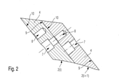
図2は、2つの直接隣接する案内翼2(i)および2(i+1)の内側シュラウド4の領域において図1の案内翼配置1を貫く断面図を示している。案内翼2(i)、2(i+1)の各々の内側シュラウド4へと、第1の孔7と第2の孔8とが各々の場合で導入される。案内翼2(i)の内側シュラウド4の第1の孔7が、周方向に見て第1の側9に直接隣接する案内翼2(i+1)の内側シュラウド4へと導入される第2の孔8と位置合わせされ、一方、案内翼2(i)の内側シュラウド4の第2の孔8が、周方向に見て第2の側10に直接隣接する案内翼2(i-1)(図2において示されていない)の内側シュラウド4へと導入される第1の孔7と位置合わせされるような手法で、これらの孔7、8の両方が案内翼2の内側シュラウド4へと導入される。
FIG. 2 shows a cross-sectional view through the
周方向に見て第1の側9において、案内翼2(i)の内側シュラウド4は、この側9において直接隣接する案内翼2(i+1)の内側シュラウド4へと導入される第1の孔7を覆い、周方向に見て第2の側10において、この第2の側10において直接隣接する案内翼2(i-1)(図2において示されていない)の内側シュラウド4へと導入される第2の孔8を覆う。
On the
したがって、本発明は、案内翼配置1の案内翼2の内側シュラウド4に第1の孔7および第2の孔8を導入することを意図しており、第1の孔7および第2の孔8は、直接隣接する案内翼2、延いては、直接隣接する内側シュラウド4の領域で、互いに位置合わせされるような手法で、案内翼2へと、つまり、案内翼2の内側シュラウドに導入される。
Therefore, the present invention is intended to introduce a
直接隣接する案内翼2または直接隣接する内側シュラウド4の位置合わせされた孔7、8を通じて、図示されていない連結要素が延び、それによって、それぞれの直接隣接する案内翼2同士がそれらの内側シュラウド4の領域において連結される。
Connecting elements (not shown) extend through the aligned
図2に例示の実施形態では、それぞれの案内翼2のそれぞれの内側シュラウド4のそれぞれの第1の孔7は、貫通孔として具現化されており、それぞれの案内翼2のそれぞれの内側シュラウド4のそれぞれの第2の孔8は、ネジ孔として具現化されている。したがってこの場合、ネジは、それぞれのネジ頭部で、止まり穴の孔として設計されたそれぞれの第1の孔7へと延び、それぞれのネジ山部で、それぞれの第2の孔8へと延びる連結要素として、採用される。
In the embodiment illustrated in FIG. 2, each
内側シュラウド4の領域における2つの直接隣接する案内翼2の連結に続いて、さらなる案内翼2が径方向に案内翼環体6へと挿入され、その案内翼2の内側シュラウド4は、2つの案内翼2の間の先に形成されたネジ連結、または、一方の側におけるそれぞれの位置合わせされた孔7、8を覆う。したがって、特に、案内翼2の連結がそれらの内側シュラウド4の領域において連結解除されるべきときでさえ、対応する連結要素が内側シュラウド4の領域におけるそれらの位置に保持されることが確保される。したがって、連結要素はターボ機械の回転子の領域に入らず、回転子を損傷し得ない。
Following the connection of two directly
図3は、本発明による案内翼配置の改作を示しており、第1の孔7と、それぞれの案内翼2の内側シュラウド4へと導入される第2の孔8との両方が貫通孔として形成されている。この場合、優先的には、ネジが連結要素として同様に採用され、それぞれのネジは、ネジ頭部が、それぞれの孔7または8の一方へと延び入り、ネジ山部が、それぞれの他方の孔8または9へと延び入り、その他方の孔8または9は次に、それぞれのネジ山部と相互作用するナットを受け入れる。
FIG. 3 shows an modification of the guide wing arrangement according to the present invention, in which both the
本発明による案内翼配置のさらなる改作が図4に示されており、図4では、図3に一致する孔7、8がここでも貫通孔として設計されているが、いわゆる止まり穴の孔としてではなく、楔形とされた孔として設計されている。次に、楔止ピンまたは平行ピンとして設計された連結要素が、これらの孔と相互作用し、各々の楔止ピンは、直接隣接する案内翼2の直接隣接するシュラウド4の2つの位置合わせされた孔7、8を通じて延びる。これらの孔7、8は、断面が円錐状、漏斗状、または円錐台状の輪郭とされている。
A further modification of the guide wing arrangement according to the present invention is shown in FIG. 4, where the
案内翼2または内側シュラウド4の領域において、それぞれの内側シュラウド4を伴う直接隣接する案内翼が続く内側シュラウドの側9、10において、軸方向に対して斜めに設定された内側シュラウド4の境界面が延びている。孔7、8の長手方向中心軸は、内側シュラウド4のこれらの境界面に対して垂直に延びており、したがって、側9、10に対して垂直に延びている。
In the area of the
それぞれの内側シュラウド4のそれぞれの周位置における接線と、孔7、8の中心軸は、1°から6°の間の角度、好ましくは2°から5°の間の角度、特に好ましくは3°から4°の間の角度を含み、そのため、それぞれの位置合わせされた孔7、8は直線上に延びており、案内翼2の周囲に、それらの内側シュラウド4の領域でおおよそ続いている。このために必要な角度は、案内翼配置における翼の数から得られる。
The tangents at the respective perimeters of each
したがって、本発明では、案内翼配置1の案内翼2の内側シュラウド4の領域におけるまったく新しい連結の種類が提案されている(または同じく外側シュラウドにおいても)。案内翼2の内側シュラウド4へと、優先的には2つずつの孔が導入され、各々の案内翼2の内側シュラウド4の側9、10では、直接隣接する案内翼、延いては、直接隣接する内側シュラウド4の2つの孔7、8が位置合わせされ、それらの孔を通じて、内側シュラウド4の領域において案内翼2を連結するための連結要素が延び、それらの連結要素の位置のため、連結要素は他の隣接する案内翼2の内側シュラウド4によって覆われ、そのため連結要素は、特にはこれらが連結解除されることになるときでさえ、孔7、8から落ちる可能性がなく、ターボ機械の回転子の領域に達する可能性がない。
Therefore, the present invention proposes a completely new type of connection in the region of the
本発明は、タービンおよび圧縮機の両方で、異なる寸法の異なるターボ機械で採用できる。特に好ましくは、本発明は、蒸気タービンのための案内翼配置で採用される。 The present invention can be used in both turbines and compressors with different turbomachines of different dimensions. Particularly preferably, the present invention is employed in guide blade arrangements for steam turbines.
1 案内翼配置
2 案内翼
3 案内翼板
4 内側シュラウド
6 案内翼環体
7 第1の孔
8 第2の孔
9 第1の側
10 第2の側
1 Guide wing arrangement
2 Guide wing
3 Guide wing plate
4 inner shroud
6 Guide wing ring
7 1st hole
8 Second hole
9 First side
10 Second side
Claims (8)
前記案内翼配置の周方向に互いに隣り合って配置される複数の案内翼(2)を備え、各々の前記案内翼(2)は内側シュラウド(4)を備え、該内側シュラウド上では前記案内翼(2)が互いに連結されており、
それぞれの前記案内翼(2)の前記内側シュラウド(4)の第1の孔(7)が、周方向に見て第1の側(9)に直接隣接する案内翼(2)の前記内側シュラウド(4)へと導入される第2の孔(8)と位置合わせされ、且つそれぞれの前記案内翼(2)の前記内側シュラウド(4)の前記第2の孔(8)が、周方向に見て第2の側(10)に直接隣接する案内翼(2)の前記内側シュラウド(4)へと導入される前記第1の孔(7)と位置合わせされるような手法で、前記第1の孔(7)および前記第2の孔(8)が前記案内翼(2)の前記内側シュラウド(4)へと導入されており、
前記内側シュラウド(4)の前記第1の側(9)および前記第2の側(10)は該案内翼配置(1)の軸方向に対して斜めに設定されており、
前記直接隣接する案内翼(2)同士の位置合わせされた前記孔(7、8)を通じて連結要素が延び、それによって、それぞれの直接隣接する案内翼(2)同士がそれらの前記内側シュラウド(4)の領域において連結されており、
前記第1および第2の孔(7、8)は、前記内側シュラウド(4)の互いに隣接する側(9、10)または境界面に対して垂直に延びており、
任意の一の内側シュラウド(4)における前記第1の孔(7)と前記第2の孔(8)との位置関係は、該内側シュラウド(4)に隣接する内側シュラウド(4)における第1の孔(7)と第2の孔(8)との位置関係と同じである
ことを特徴とする案内翼配置(1)。 The guide wing arrangement (1) of the turbomachine,
The guide blades (2) are provided with a plurality of guide blades (2) arranged adjacent to each other in the circumferential direction of the guide blade arrangement, and each of the guide blades (2) is provided with an inner shroud (4), and the guide blade is provided on the inner shroud. (2) are connected to each other,
The inner shroud of the guide wing (2) in which the first hole (7) of the inner shroud (4) of each guide wing (2) is directly adjacent to the first side (9) when viewed in the circumferential direction. The second hole (8) of the inner shroud (4) of each of the guide blades (2) is aligned with the second hole (8) introduced into (4), and the second hole (8) is circumferentially oriented. The first hole (7) is aligned with the first hole (7) introduced into the inner shroud (4) of the guide blade (2) directly adjacent to the second side (10). The hole (7) and the second hole (8) are introduced into the inner shroud (4) of the guide blade (2).
The first side (9) and the second side (10) of the inner shroud (4) are set obliquely with respect to the axial direction of the guide blade arrangement (1).
The connecting elements extend through the aligned holes (7, 8) between the directly adjacent guide blades (2), whereby the respective directly adjacent guide blades (2) are respectively their inner shrouds (4). ) Are connected in the area of)
The first and second holes (7, 8) extend perpendicular to the adjacent sides (9, 10) or interface of the inner shroud (4).
The positional relationship between the first hole (7) and the second hole (8) in any one inner shroud (4) is the first in the inner shroud (4) adjacent to the inner shroud (4). It is the same as the positional relationship between the hole (7) and the second hole (8).
Guide wing arrangement characterized by this (1).
Applications Claiming Priority (2)
| Application Number | Priority Date | Filing Date | Title |
|---|---|---|---|
| DE102016113912.2A DE102016113912A1 (en) | 2016-07-28 | 2016-07-28 | Guide vane arrangement of a turbomachine |
| DE102016113912.2 | 2016-07-28 |
Publications (2)
| Publication Number | Publication Date |
|---|---|
| JP2018017236A JP2018017236A (en) | 2018-02-01 |
| JP6991007B2 true JP6991007B2 (en) | 2022-01-12 |
Family
ID=60951466
Family Applications (1)
| Application Number | Title | Priority Date | Filing Date |
|---|---|---|---|
| JP2017145249A Active JP6991007B2 (en) | 2016-07-28 | 2017-07-27 | Turbomachinery guide wing arrangement |
Country Status (5)
| Country | Link |
|---|---|
| JP (1) | JP6991007B2 (en) |
| KR (1) | KR102365584B1 (en) |
| CN (1) | CN107664044A (en) |
| CH (1) | CH712765B1 (en) |
| DE (1) | DE102016113912A1 (en) |
Families Citing this family (1)
| Publication number | Priority date | Publication date | Assignee | Title |
|---|---|---|---|---|
| DE102020115106B4 (en) * | 2020-06-08 | 2022-08-25 | Man Energy Solutions Se | turbine nozzle |
Citations (1)
| Publication number | Priority date | Publication date | Assignee | Title |
|---|---|---|---|---|
| EP1707743A1 (en) | 2005-03-18 | 2006-10-04 | Siemens Aktiengesellschaft | Segment with minimum two blades, turbine element and method to mount a segment |
Family Cites Families (7)
| Publication number | Priority date | Publication date | Assignee | Title |
|---|---|---|---|---|
| JPS52143311A (en) * | 1976-05-24 | 1977-11-29 | Toshiba Corp | Movable blade connecting apparatus of turbo machinery |
| JPH10196308A (en) * | 1997-01-10 | 1998-07-28 | Mitsubishi Heavy Ind Ltd | Integrated segment structure stationary blade and manufacture therefor |
| DE69824925T2 (en) * | 1997-09-17 | 2005-08-25 | Mitsubishi Heavy Industries, Ltd. | Leitschaufelpaar |
| US6158104A (en) * | 1999-08-11 | 2000-12-12 | General Electric Co. | Assembly jig for use with integrally covered bucket blades |
| US7591634B2 (en) * | 2006-11-21 | 2009-09-22 | General Electric Company | Stator shim welding |
| DE102010041808B4 (en) * | 2010-09-30 | 2014-10-23 | Siemens Aktiengesellschaft | Blade segment, turbomachinery and process for their preparation |
| JP5342579B2 (en) * | 2011-02-28 | 2013-11-13 | 三菱重工業株式会社 | Stator blade unit of rotating machine, method of manufacturing stator blade unit of rotating machine, and method of coupling stator blade unit of rotating machine |
-
2016
- 2016-07-28 DE DE102016113912.2A patent/DE102016113912A1/en active Pending
-
2017
- 2017-05-29 CH CH00694/17A patent/CH712765B1/en unknown
- 2017-07-26 KR KR1020170094476A patent/KR102365584B1/en active Active
- 2017-07-27 JP JP2017145249A patent/JP6991007B2/en active Active
- 2017-07-28 CN CN201710629683.0A patent/CN107664044A/en active Pending
Patent Citations (1)
| Publication number | Priority date | Publication date | Assignee | Title |
|---|---|---|---|---|
| EP1707743A1 (en) | 2005-03-18 | 2006-10-04 | Siemens Aktiengesellschaft | Segment with minimum two blades, turbine element and method to mount a segment |
Also Published As
| Publication number | Publication date |
|---|---|
| CH712765B1 (en) | 2021-03-31 |
| KR20180013752A (en) | 2018-02-07 |
| CN107664044A (en) | 2018-02-06 |
| DE102016113912A1 (en) | 2018-02-01 |
| KR102365584B1 (en) | 2022-02-18 |
| CH712765A2 (en) | 2018-01-31 |
| JP2018017236A (en) | 2018-02-01 |
Similar Documents
| Publication | Publication Date | Title |
|---|---|---|
| JP4886735B2 (en) | Turbine blade assembly and steam turbine | |
| US10132326B2 (en) | Impeller for axial fans | |
| CN101956575B (en) | Turbine bucket lockwire rotation prevention | |
| JP5611015B2 (en) | Turbine equipment | |
| CN107975389B (en) | Rotating assembly of a turbomachine equipped with an axial retention system of the blades | |
| US7114927B2 (en) | Fixing method for the blading of a fluid-flow machine and fixing arrangement | |
| JP5890601B2 (en) | Rotor assembly of turbomachine and its assembly method | |
| US10047615B2 (en) | Method of mounting rotor blades on a rotor disk, and clamping device for performing such a method | |
| US20170198710A1 (en) | Compressor usable within a gas turbine engine | |
| JP2004340131A (en) | Rotor cascade of fluid machinery | |
| JP6991007B2 (en) | Turbomachinery guide wing arrangement | |
| CA2855670A1 (en) | Stator blade sector for an axial turbomachine with a dual means of fixing | |
| RU2398113C2 (en) | Turbine wheel (versions) and attachment of turbine wheel and vane | |
| EP2811117A3 (en) | Shroud assembly for a turbo engine | |
| KR102270498B1 (en) | Turbomachinery rotor and manufacturing method thereof | |
| US9151163B2 (en) | Turbomachine rotor disk | |
| JP5090287B2 (en) | Turbine blade and its fixed structure | |
| CN112189097B (en) | Improved turbine fan tray | |
| US10738624B2 (en) | Rotor device of a turbomachine | |
| US20240035385A1 (en) | Turbomachine rotor having improved vibratory behaviour | |
| EP3058180B1 (en) | Fan rotor with integrated platform attachment | |
| JP6329471B2 (en) | Turbine | |
| JP6258493B2 (en) | Insert element, ring segment, gas turbine, mounting method | |
| RU158311U1 (en) | AXIAL FAN BLADE FASTENING ASSEMBLY | |
| EP2573327A1 (en) | Damping wire, corresponding rotor blade stage, steam turbine and producing method |
Legal Events
| Date | Code | Title | Description |
|---|---|---|---|
| A621 | Written request for application examination |
Free format text: JAPANESE INTERMEDIATE CODE: A621 Effective date: 20200207 |
|
| A977 | Report on retrieval |
Free format text: JAPANESE INTERMEDIATE CODE: A971007 Effective date: 20201217 |
|
| A131 | Notification of reasons for refusal |
Free format text: JAPANESE INTERMEDIATE CODE: A131 Effective date: 20210201 |
|
| A521 | Request for written amendment filed |
Free format text: JAPANESE INTERMEDIATE CODE: A523 Effective date: 20210407 |
|
| A131 | Notification of reasons for refusal |
Free format text: JAPANESE INTERMEDIATE CODE: A131 Effective date: 20210524 |
|
| A601 | Written request for extension of time |
Free format text: JAPANESE INTERMEDIATE CODE: A601 Effective date: 20210824 |
|
| A521 | Request for written amendment filed |
Free format text: JAPANESE INTERMEDIATE CODE: A523 Effective date: 20211021 |
|
| TRDD | Decision of grant or rejection written | ||
| A01 | Written decision to grant a patent or to grant a registration (utility model) |
Free format text: JAPANESE INTERMEDIATE CODE: A01 Effective date: 20211108 |
|
| A61 | First payment of annual fees (during grant procedure) |
Free format text: JAPANESE INTERMEDIATE CODE: A61 Effective date: 20211207 |
|
| R150 | Certificate of patent or registration of utility model |
Ref document number: 6991007 Country of ref document: JP Free format text: JAPANESE INTERMEDIATE CODE: R150 |
|
| R250 | Receipt of annual fees |
Free format text: JAPANESE INTERMEDIATE CODE: R250 |
|
| S533 | Written request for registration of change of name |
Free format text: JAPANESE INTERMEDIATE CODE: R313533 |
|
| R350 | Written notification of registration of transfer |
Free format text: JAPANESE INTERMEDIATE CODE: R350 |
|
| R250 | Receipt of annual fees |
Free format text: JAPANESE INTERMEDIATE CODE: R250 |