JP6989340B2 - Systems and methods to increase the efficiency of heating cold fluids flowing through conduits - Google Patents
Systems and methods to increase the efficiency of heating cold fluids flowing through conduits Download PDFInfo
- Publication number
- JP6989340B2 JP6989340B2 JP2017200724A JP2017200724A JP6989340B2 JP 6989340 B2 JP6989340 B2 JP 6989340B2 JP 2017200724 A JP2017200724 A JP 2017200724A JP 2017200724 A JP2017200724 A JP 2017200724A JP 6989340 B2 JP6989340 B2 JP 6989340B2
- Authority
- JP
- Japan
- Prior art keywords
- valve
- upstream
- downstream
- cold fluid
- fluid
- Prior art date
- Legal status (The legal status is an assumption and is not a legal conclusion. Google has not performed a legal analysis and makes no representation as to the accuracy of the status listed.)
- Active
Links
Images


Classifications
-
- F—MECHANICAL ENGINEERING; LIGHTING; HEATING; WEAPONS; BLASTING
- F02—COMBUSTION ENGINES; HOT-GAS OR COMBUSTION-PRODUCT ENGINE PLANTS
- F02K—JET-PROPULSION PLANTS
- F02K9/00—Rocket-engine plants, i.e. plants carrying both fuel and oxidant therefor; Control thereof
- F02K9/42—Rocket-engine plants, i.e. plants carrying both fuel and oxidant therefor; Control thereof using liquid or gaseous propellants
- F02K9/44—Feeding propellants
-
- F—MECHANICAL ENGINEERING; LIGHTING; HEATING; WEAPONS; BLASTING
- F02—COMBUSTION ENGINES; HOT-GAS OR COMBUSTION-PRODUCT ENGINE PLANTS
- F02K—JET-PROPULSION PLANTS
- F02K9/00—Rocket-engine plants, i.e. plants carrying both fuel and oxidant therefor; Control thereof
- F02K9/42—Rocket-engine plants, i.e. plants carrying both fuel and oxidant therefor; Control thereof using liquid or gaseous propellants
- F02K9/60—Constructional parts; Details not otherwise provided for
-
- F—MECHANICAL ENGINEERING; LIGHTING; HEATING; WEAPONS; BLASTING
- F17—STORING OR DISTRIBUTING GASES OR LIQUIDS
- F17C—VESSELS FOR CONTAINING OR STORING COMPRESSED, LIQUEFIED OR SOLIDIFIED GASES; FIXED-CAPACITY GAS-HOLDERS; FILLING VESSELS WITH, OR DISCHARGING FROM VESSELS, COMPRESSED, LIQUEFIED, OR SOLIDIFIED GASES
- F17C13/00—Details of vessels or of the filling or discharging of vessels
- F17C13/001—Thermal insulation specially adapted for cryogenic vessels
-
- F—MECHANICAL ENGINEERING; LIGHTING; HEATING; WEAPONS; BLASTING
- F17—STORING OR DISTRIBUTING GASES OR LIQUIDS
- F17C—VESSELS FOR CONTAINING OR STORING COMPRESSED, LIQUEFIED OR SOLIDIFIED GASES; FIXED-CAPACITY GAS-HOLDERS; FILLING VESSELS WITH, OR DISCHARGING FROM VESSELS, COMPRESSED, LIQUEFIED, OR SOLIDIFIED GASES
- F17C13/00—Details of vessels or of the filling or discharging of vessels
- F17C13/04—Arrangement or mounting of valves
-
- F—MECHANICAL ENGINEERING; LIGHTING; HEATING; WEAPONS; BLASTING
- F17—STORING OR DISTRIBUTING GASES OR LIQUIDS
- F17C—VESSELS FOR CONTAINING OR STORING COMPRESSED, LIQUEFIED OR SOLIDIFIED GASES; FIXED-CAPACITY GAS-HOLDERS; FILLING VESSELS WITH, OR DISCHARGING FROM VESSELS, COMPRESSED, LIQUEFIED, OR SOLIDIFIED GASES
- F17C9/00—Methods or apparatus for discharging liquefied or solidified gases from vessels not under pressure
-
- F—MECHANICAL ENGINEERING; LIGHTING; HEATING; WEAPONS; BLASTING
- F02—COMBUSTION ENGINES; HOT-GAS OR COMBUSTION-PRODUCT ENGINE PLANTS
- F02K—JET-PROPULSION PLANTS
- F02K9/00—Rocket-engine plants, i.e. plants carrying both fuel and oxidant therefor; Control thereof
- F02K9/42—Rocket-engine plants, i.e. plants carrying both fuel and oxidant therefor; Control thereof using liquid or gaseous propellants
- F02K9/44—Feeding propellants
- F02K9/56—Control
- F02K9/58—Propellant feed valves
-
- F—MECHANICAL ENGINEERING; LIGHTING; HEATING; WEAPONS; BLASTING
- F05—INDEXING SCHEMES RELATING TO ENGINES OR PUMPS IN VARIOUS SUBCLASSES OF CLASSES F01-F04
- F05D—INDEXING SCHEME FOR ASPECTS RELATING TO NON-POSITIVE-DISPLACEMENT MACHINES OR ENGINES, GAS-TURBINES OR JET-PROPULSION PLANTS
- F05D2260/00—Function
- F05D2260/20—Heat transfer, e.g. cooling
- F05D2260/221—Improvement of heat transfer
-
- F—MECHANICAL ENGINEERING; LIGHTING; HEATING; WEAPONS; BLASTING
- F17—STORING OR DISTRIBUTING GASES OR LIQUIDS
- F17C—VESSELS FOR CONTAINING OR STORING COMPRESSED, LIQUEFIED OR SOLIDIFIED GASES; FIXED-CAPACITY GAS-HOLDERS; FILLING VESSELS WITH, OR DISCHARGING FROM VESSELS, COMPRESSED, LIQUEFIED, OR SOLIDIFIED GASES
- F17C2201/00—Vessel construction, in particular geometry, arrangement or size
- F17C2201/01—Shape
- F17C2201/0104—Shape cylindrical
- F17C2201/0109—Shape cylindrical with exteriorly curved end-piece
-
- F—MECHANICAL ENGINEERING; LIGHTING; HEATING; WEAPONS; BLASTING
- F17—STORING OR DISTRIBUTING GASES OR LIQUIDS
- F17C—VESSELS FOR CONTAINING OR STORING COMPRESSED, LIQUEFIED OR SOLIDIFIED GASES; FIXED-CAPACITY GAS-HOLDERS; FILLING VESSELS WITH, OR DISCHARGING FROM VESSELS, COMPRESSED, LIQUEFIED, OR SOLIDIFIED GASES
- F17C2201/00—Vessel construction, in particular geometry, arrangement or size
- F17C2201/05—Size
- F17C2201/054—Size medium (>1 m3)
-
- F—MECHANICAL ENGINEERING; LIGHTING; HEATING; WEAPONS; BLASTING
- F17—STORING OR DISTRIBUTING GASES OR LIQUIDS
- F17C—VESSELS FOR CONTAINING OR STORING COMPRESSED, LIQUEFIED OR SOLIDIFIED GASES; FIXED-CAPACITY GAS-HOLDERS; FILLING VESSELS WITH, OR DISCHARGING FROM VESSELS, COMPRESSED, LIQUEFIED, OR SOLIDIFIED GASES
- F17C2205/00—Vessel construction, in particular mounting arrangements, attachments or identifications means
- F17C2205/01—Mounting arrangements
- F17C2205/0123—Mounting arrangements characterised by number of vessels
- F17C2205/013—Two or more vessels
-
- F—MECHANICAL ENGINEERING; LIGHTING; HEATING; WEAPONS; BLASTING
- F17—STORING OR DISTRIBUTING GASES OR LIQUIDS
- F17C—VESSELS FOR CONTAINING OR STORING COMPRESSED, LIQUEFIED OR SOLIDIFIED GASES; FIXED-CAPACITY GAS-HOLDERS; FILLING VESSELS WITH, OR DISCHARGING FROM VESSELS, COMPRESSED, LIQUEFIED, OR SOLIDIFIED GASES
- F17C2205/00—Vessel construction, in particular mounting arrangements, attachments or identifications means
- F17C2205/03—Fluid connections, filters, valves, closure means or other attachments
- F17C2205/0302—Fittings, valves, filters, or components in connection with the gas storage device
- F17C2205/0323—Valves
- F17C2205/0326—Valves electrically actuated
-
- F—MECHANICAL ENGINEERING; LIGHTING; HEATING; WEAPONS; BLASTING
- F17—STORING OR DISTRIBUTING GASES OR LIQUIDS
- F17C—VESSELS FOR CONTAINING OR STORING COMPRESSED, LIQUEFIED OR SOLIDIFIED GASES; FIXED-CAPACITY GAS-HOLDERS; FILLING VESSELS WITH, OR DISCHARGING FROM VESSELS, COMPRESSED, LIQUEFIED, OR SOLIDIFIED GASES
- F17C2221/00—Handled fluid, in particular type of fluid
- F17C2221/01—Pure fluids
- F17C2221/011—Oxygen
-
- F—MECHANICAL ENGINEERING; LIGHTING; HEATING; WEAPONS; BLASTING
- F17—STORING OR DISTRIBUTING GASES OR LIQUIDS
- F17C—VESSELS FOR CONTAINING OR STORING COMPRESSED, LIQUEFIED OR SOLIDIFIED GASES; FIXED-CAPACITY GAS-HOLDERS; FILLING VESSELS WITH, OR DISCHARGING FROM VESSELS, COMPRESSED, LIQUEFIED, OR SOLIDIFIED GASES
- F17C2221/00—Handled fluid, in particular type of fluid
- F17C2221/01—Pure fluids
- F17C2221/012—Hydrogen
-
- F—MECHANICAL ENGINEERING; LIGHTING; HEATING; WEAPONS; BLASTING
- F17—STORING OR DISTRIBUTING GASES OR LIQUIDS
- F17C—VESSELS FOR CONTAINING OR STORING COMPRESSED, LIQUEFIED OR SOLIDIFIED GASES; FIXED-CAPACITY GAS-HOLDERS; FILLING VESSELS WITH, OR DISCHARGING FROM VESSELS, COMPRESSED, LIQUEFIED, OR SOLIDIFIED GASES
- F17C2221/00—Handled fluid, in particular type of fluid
- F17C2221/03—Mixtures
- F17C2221/032—Hydrocarbons
- F17C2221/033—Methane, e.g. natural gas, CNG, LNG, GNL, GNC, PLNG
-
- F—MECHANICAL ENGINEERING; LIGHTING; HEATING; WEAPONS; BLASTING
- F17—STORING OR DISTRIBUTING GASES OR LIQUIDS
- F17C—VESSELS FOR CONTAINING OR STORING COMPRESSED, LIQUEFIED OR SOLIDIFIED GASES; FIXED-CAPACITY GAS-HOLDERS; FILLING VESSELS WITH, OR DISCHARGING FROM VESSELS, COMPRESSED, LIQUEFIED, OR SOLIDIFIED GASES
- F17C2221/00—Handled fluid, in particular type of fluid
- F17C2221/08—Ergols, e.g. hydrazine
-
- F—MECHANICAL ENGINEERING; LIGHTING; HEATING; WEAPONS; BLASTING
- F17—STORING OR DISTRIBUTING GASES OR LIQUIDS
- F17C—VESSELS FOR CONTAINING OR STORING COMPRESSED, LIQUEFIED OR SOLIDIFIED GASES; FIXED-CAPACITY GAS-HOLDERS; FILLING VESSELS WITH, OR DISCHARGING FROM VESSELS, COMPRESSED, LIQUEFIED, OR SOLIDIFIED GASES
- F17C2223/00—Handled fluid before transfer, i.e. state of fluid when stored in the vessel or before transfer from the vessel
- F17C2223/01—Handled fluid before transfer, i.e. state of fluid when stored in the vessel or before transfer from the vessel characterised by the phase
- F17C2223/0107—Single phase
- F17C2223/013—Single phase liquid
-
- F—MECHANICAL ENGINEERING; LIGHTING; HEATING; WEAPONS; BLASTING
- F17—STORING OR DISTRIBUTING GASES OR LIQUIDS
- F17C—VESSELS FOR CONTAINING OR STORING COMPRESSED, LIQUEFIED OR SOLIDIFIED GASES; FIXED-CAPACITY GAS-HOLDERS; FILLING VESSELS WITH, OR DISCHARGING FROM VESSELS, COMPRESSED, LIQUEFIED, OR SOLIDIFIED GASES
- F17C2223/00—Handled fluid before transfer, i.e. state of fluid when stored in the vessel or before transfer from the vessel
- F17C2223/01—Handled fluid before transfer, i.e. state of fluid when stored in the vessel or before transfer from the vessel characterised by the phase
- F17C2223/0146—Two-phase
- F17C2223/0153—Liquefied gas, e.g. LPG, GPL
- F17C2223/0161—Liquefied gas, e.g. LPG, GPL cryogenic, e.g. LNG, GNL, PLNG
-
- F—MECHANICAL ENGINEERING; LIGHTING; HEATING; WEAPONS; BLASTING
- F17—STORING OR DISTRIBUTING GASES OR LIQUIDS
- F17C—VESSELS FOR CONTAINING OR STORING COMPRESSED, LIQUEFIED OR SOLIDIFIED GASES; FIXED-CAPACITY GAS-HOLDERS; FILLING VESSELS WITH, OR DISCHARGING FROM VESSELS, COMPRESSED, LIQUEFIED, OR SOLIDIFIED GASES
- F17C2223/00—Handled fluid before transfer, i.e. state of fluid when stored in the vessel or before transfer from the vessel
- F17C2223/03—Handled fluid before transfer, i.e. state of fluid when stored in the vessel or before transfer from the vessel characterised by the pressure level
- F17C2223/033—Small pressure, e.g. for liquefied gas
-
- F—MECHANICAL ENGINEERING; LIGHTING; HEATING; WEAPONS; BLASTING
- F17—STORING OR DISTRIBUTING GASES OR LIQUIDS
- F17C—VESSELS FOR CONTAINING OR STORING COMPRESSED, LIQUEFIED OR SOLIDIFIED GASES; FIXED-CAPACITY GAS-HOLDERS; FILLING VESSELS WITH, OR DISCHARGING FROM VESSELS, COMPRESSED, LIQUEFIED, OR SOLIDIFIED GASES
- F17C2225/00—Handled fluid after transfer, i.e. state of fluid after transfer from the vessel
- F17C2225/01—Handled fluid after transfer, i.e. state of fluid after transfer from the vessel characterised by the phase
- F17C2225/0107—Single phase
- F17C2225/0123—Single phase gaseous, e.g. CNG, GNC
-
- F—MECHANICAL ENGINEERING; LIGHTING; HEATING; WEAPONS; BLASTING
- F17—STORING OR DISTRIBUTING GASES OR LIQUIDS
- F17C—VESSELS FOR CONTAINING OR STORING COMPRESSED, LIQUEFIED OR SOLIDIFIED GASES; FIXED-CAPACITY GAS-HOLDERS; FILLING VESSELS WITH, OR DISCHARGING FROM VESSELS, COMPRESSED, LIQUEFIED, OR SOLIDIFIED GASES
- F17C2225/00—Handled fluid after transfer, i.e. state of fluid after transfer from the vessel
- F17C2225/01—Handled fluid after transfer, i.e. state of fluid after transfer from the vessel characterised by the phase
- F17C2225/0107—Single phase
- F17C2225/013—Single phase liquid
-
- F—MECHANICAL ENGINEERING; LIGHTING; HEATING; WEAPONS; BLASTING
- F17—STORING OR DISTRIBUTING GASES OR LIQUIDS
- F17C—VESSELS FOR CONTAINING OR STORING COMPRESSED, LIQUEFIED OR SOLIDIFIED GASES; FIXED-CAPACITY GAS-HOLDERS; FILLING VESSELS WITH, OR DISCHARGING FROM VESSELS, COMPRESSED, LIQUEFIED, OR SOLIDIFIED GASES
- F17C2225/00—Handled fluid after transfer, i.e. state of fluid after transfer from the vessel
- F17C2225/03—Handled fluid after transfer, i.e. state of fluid after transfer from the vessel characterised by the pressure level
- F17C2225/033—Small pressure, e.g. for liquefied gas
-
- F—MECHANICAL ENGINEERING; LIGHTING; HEATING; WEAPONS; BLASTING
- F17—STORING OR DISTRIBUTING GASES OR LIQUIDS
- F17C—VESSELS FOR CONTAINING OR STORING COMPRESSED, LIQUEFIED OR SOLIDIFIED GASES; FIXED-CAPACITY GAS-HOLDERS; FILLING VESSELS WITH, OR DISCHARGING FROM VESSELS, COMPRESSED, LIQUEFIED, OR SOLIDIFIED GASES
- F17C2227/00—Transfer of fluids, i.e. method or means for transferring the fluid; Heat exchange with the fluid
- F17C2227/01—Propulsion of the fluid
- F17C2227/0121—Propulsion of the fluid by gravity
-
- F—MECHANICAL ENGINEERING; LIGHTING; HEATING; WEAPONS; BLASTING
- F17—STORING OR DISTRIBUTING GASES OR LIQUIDS
- F17C—VESSELS FOR CONTAINING OR STORING COMPRESSED, LIQUEFIED OR SOLIDIFIED GASES; FIXED-CAPACITY GAS-HOLDERS; FILLING VESSELS WITH, OR DISCHARGING FROM VESSELS, COMPRESSED, LIQUEFIED, OR SOLIDIFIED GASES
- F17C2227/00—Transfer of fluids, i.e. method or means for transferring the fluid; Heat exchange with the fluid
- F17C2227/03—Heat exchange with the fluid
- F17C2227/0302—Heat exchange with the fluid by heating
- F17C2227/0304—Heat exchange with the fluid by heating using an electric heater
-
- F—MECHANICAL ENGINEERING; LIGHTING; HEATING; WEAPONS; BLASTING
- F17—STORING OR DISTRIBUTING GASES OR LIQUIDS
- F17C—VESSELS FOR CONTAINING OR STORING COMPRESSED, LIQUEFIED OR SOLIDIFIED GASES; FIXED-CAPACITY GAS-HOLDERS; FILLING VESSELS WITH, OR DISCHARGING FROM VESSELS, COMPRESSED, LIQUEFIED, OR SOLIDIFIED GASES
- F17C2227/00—Transfer of fluids, i.e. method or means for transferring the fluid; Heat exchange with the fluid
- F17C2227/03—Heat exchange with the fluid
- F17C2227/0302—Heat exchange with the fluid by heating
- F17C2227/0309—Heat exchange with the fluid by heating using another fluid
- F17C2227/0311—Air heating
-
- F—MECHANICAL ENGINEERING; LIGHTING; HEATING; WEAPONS; BLASTING
- F17—STORING OR DISTRIBUTING GASES OR LIQUIDS
- F17C—VESSELS FOR CONTAINING OR STORING COMPRESSED, LIQUEFIED OR SOLIDIFIED GASES; FIXED-CAPACITY GAS-HOLDERS; FILLING VESSELS WITH, OR DISCHARGING FROM VESSELS, COMPRESSED, LIQUEFIED, OR SOLIDIFIED GASES
- F17C2227/00—Transfer of fluids, i.e. method or means for transferring the fluid; Heat exchange with the fluid
- F17C2227/03—Heat exchange with the fluid
- F17C2227/0302—Heat exchange with the fluid by heating
- F17C2227/0334—Heat exchange with the fluid by heating by radiation means
-
- F—MECHANICAL ENGINEERING; LIGHTING; HEATING; WEAPONS; BLASTING
- F17—STORING OR DISTRIBUTING GASES OR LIQUIDS
- F17C—VESSELS FOR CONTAINING OR STORING COMPRESSED, LIQUEFIED OR SOLIDIFIED GASES; FIXED-CAPACITY GAS-HOLDERS; FILLING VESSELS WITH, OR DISCHARGING FROM VESSELS, COMPRESSED, LIQUEFIED, OR SOLIDIFIED GASES
- F17C2227/00—Transfer of fluids, i.e. method or means for transferring the fluid; Heat exchange with the fluid
- F17C2227/03—Heat exchange with the fluid
- F17C2227/0367—Localisation of heat exchange
- F17C2227/0388—Localisation of heat exchange separate
- F17C2227/039—Localisation of heat exchange separate on the pipes
-
- F—MECHANICAL ENGINEERING; LIGHTING; HEATING; WEAPONS; BLASTING
- F17—STORING OR DISTRIBUTING GASES OR LIQUIDS
- F17C—VESSELS FOR CONTAINING OR STORING COMPRESSED, LIQUEFIED OR SOLIDIFIED GASES; FIXED-CAPACITY GAS-HOLDERS; FILLING VESSELS WITH, OR DISCHARGING FROM VESSELS, COMPRESSED, LIQUEFIED, OR SOLIDIFIED GASES
- F17C2250/00—Accessories; Control means; Indicating, measuring or monitoring of parameters
- F17C2250/03—Control means
- F17C2250/032—Control means using computers
-
- F—MECHANICAL ENGINEERING; LIGHTING; HEATING; WEAPONS; BLASTING
- F17—STORING OR DISTRIBUTING GASES OR LIQUIDS
- F17C—VESSELS FOR CONTAINING OR STORING COMPRESSED, LIQUEFIED OR SOLIDIFIED GASES; FIXED-CAPACITY GAS-HOLDERS; FILLING VESSELS WITH, OR DISCHARGING FROM VESSELS, COMPRESSED, LIQUEFIED, OR SOLIDIFIED GASES
- F17C2250/00—Accessories; Control means; Indicating, measuring or monitoring of parameters
- F17C2250/04—Indicating or measuring of parameters as input values
- F17C2250/0404—Parameters indicated or measured
- F17C2250/0439—Temperature
-
- F—MECHANICAL ENGINEERING; LIGHTING; HEATING; WEAPONS; BLASTING
- F17—STORING OR DISTRIBUTING GASES OR LIQUIDS
- F17C—VESSELS FOR CONTAINING OR STORING COMPRESSED, LIQUEFIED OR SOLIDIFIED GASES; FIXED-CAPACITY GAS-HOLDERS; FILLING VESSELS WITH, OR DISCHARGING FROM VESSELS, COMPRESSED, LIQUEFIED, OR SOLIDIFIED GASES
- F17C2250/00—Accessories; Control means; Indicating, measuring or monitoring of parameters
- F17C2250/04—Indicating or measuring of parameters as input values
- F17C2250/0404—Parameters indicated or measured
- F17C2250/0443—Flow or movement of content
-
- F—MECHANICAL ENGINEERING; LIGHTING; HEATING; WEAPONS; BLASTING
- F17—STORING OR DISTRIBUTING GASES OR LIQUIDS
- F17C—VESSELS FOR CONTAINING OR STORING COMPRESSED, LIQUEFIED OR SOLIDIFIED GASES; FIXED-CAPACITY GAS-HOLDERS; FILLING VESSELS WITH, OR DISCHARGING FROM VESSELS, COMPRESSED, LIQUEFIED, OR SOLIDIFIED GASES
- F17C2260/00—Purposes of gas storage and gas handling
- F17C2260/02—Improving properties related to fluid or fluid transfer
-
- F—MECHANICAL ENGINEERING; LIGHTING; HEATING; WEAPONS; BLASTING
- F17—STORING OR DISTRIBUTING GASES OR LIQUIDS
- F17C—VESSELS FOR CONTAINING OR STORING COMPRESSED, LIQUEFIED OR SOLIDIFIED GASES; FIXED-CAPACITY GAS-HOLDERS; FILLING VESSELS WITH, OR DISCHARGING FROM VESSELS, COMPRESSED, LIQUEFIED, OR SOLIDIFIED GASES
- F17C2265/00—Effects achieved by gas storage or gas handling
- F17C2265/06—Fluid distribution
- F17C2265/066—Fluid distribution for feeding engines for propulsion
-
- F—MECHANICAL ENGINEERING; LIGHTING; HEATING; WEAPONS; BLASTING
- F17—STORING OR DISTRIBUTING GASES OR LIQUIDS
- F17C—VESSELS FOR CONTAINING OR STORING COMPRESSED, LIQUEFIED OR SOLIDIFIED GASES; FIXED-CAPACITY GAS-HOLDERS; FILLING VESSELS WITH, OR DISCHARGING FROM VESSELS, COMPRESSED, LIQUEFIED, OR SOLIDIFIED GASES
- F17C2270/00—Applications
- F17C2270/01—Applications for fluid transport or storage
- F17C2270/0186—Applications for fluid transport or storage in the air or in space
- F17C2270/0197—Rockets
-
- Y—GENERAL TAGGING OF NEW TECHNOLOGICAL DEVELOPMENTS; GENERAL TAGGING OF CROSS-SECTIONAL TECHNOLOGIES SPANNING OVER SEVERAL SECTIONS OF THE IPC; TECHNICAL SUBJECTS COVERED BY FORMER USPC CROSS-REFERENCE ART COLLECTIONS [XRACs] AND DIGESTS
- Y02—TECHNOLOGIES OR APPLICATIONS FOR MITIGATION OR ADAPTATION AGAINST CLIMATE CHANGE
- Y02E—REDUCTION OF GREENHOUSE GAS [GHG] EMISSIONS, RELATED TO ENERGY GENERATION, TRANSMISSION OR DISTRIBUTION
- Y02E60/00—Enabling technologies; Technologies with a potential or indirect contribution to GHG emissions mitigation
- Y02E60/30—Hydrogen technology
- Y02E60/32—Hydrogen storage
Landscapes
- Engineering & Computer Science (AREA)
- Mechanical Engineering (AREA)
- General Engineering & Computer Science (AREA)
- Chemical & Material Sciences (AREA)
- Combustion & Propulsion (AREA)
- Filling Or Discharging Of Gas Storage Vessels (AREA)
- Details Of Valves (AREA)
- Measuring Volume Flow (AREA)
- Flow Control (AREA)
- Thermotherapy And Cooling Therapy Devices (AREA)
Description
本開示は、一般に、低温流体に関し、より具体的には、導管を通って流れる低温流体を加熱する効率を高めるためのシステム及び方法に関する。 The present disclosure relates to cold fluids in general, and more specifically to systems and methods for increasing the efficiency of heating cold fluids flowing through conduits.
ある用途では、流体が導管の下流端で構成要素に流入する前に、導管を通って流れる流体を加熱する必要がある。例えば、液体推進材ロケットエンジンを有する打ち上げロケットは、エンジン始動中に点火及び燃焼の質を保証するために、エンジンセクションに流入する直前に、低温酸化剤(例えば、液体酸素−LOX)及び低温燃料(例えば、液体水素−LH2)を加熱する必要がある。低温促進剤を加熱することは、実際、低温促進剤タンクがエンジン上方に位置することから、複雑である。例えば、LOXは、エンジン上方のかなりの距離(例えば、100フィート以上)に位置するLOXタンクから比較的大きな直径の導管を通って下方に流れることがある。 In some applications, it is necessary to heat the fluid flowing through the conduit before it flows into the component at the downstream end of the conduit. For example, a launch vehicle with a liquid propulsion rocket engine may have a cryogenic oxidant (eg, liquid oxygen-LOX) and cryogenic fuel just before flowing into the engine section to ensure ignition and combustion quality during engine startup. (For example, liquid hydrogen-LH 2 ) needs to be heated. Heating the cryo-accelerator is complicated because the cryo-accelerator tank is actually located above the engine. For example, LOX may flow down from a LOX tank located at a considerable distance above the engine (eg, 100 feet or more) through a relatively large diameter conduit.
導管の比較的大きな直径とエンジン始動のための最初の低流要件が原因で、LOXは、最初は比較的ゆっくりと導管を移動している。導管外側に位置するヒータによるLOXの加熱中に、導管壁の内面に直接隣接するLOXは、導管内壁に沿って上に向かって移動する比較的低い密度の浮力流に変換される一方で、残りの密度の高い加熱されたLOXは、下に向かってエンジンに流入する。導管の比較的大きな直径とLOXの比較的低い流量が原因で、上に向かって移動する浮力流は、加熱されたLOXの一部を導管を通って上方に引き寄せる。 Due to the relatively large diameter of the conduit and the initial low current requirements for starting the engine, the LOX is initially moving through the conduit relatively slowly. During heating of the LOX by a heater located outside the conduit, the LOX directly adjacent to the inner surface of the conduit wall is converted into a relatively low density buoyant flow that moves upward along the inner wall of the conduit, while remaining. The dense heated LOX flows downward into the engine. Due to the relatively large diameter of the conduit and the relatively low flow rate of the LOX, the buoyant flow moving upwards draws a portion of the heated LOX upward through the conduit.
加熱されたLOXの上に向かう流れの正味の影響は、ヒータ効率の損失であり、エンジン始動のために必要とされる温度までLOXを加熱する手段として、ヒータの電力出力増加及び/又はヒータ量の増加を必要とする。残念ながら、ヒータの電力レベルが増加すると、エンジン始動システムの動作効率が低下する。ヒータの量が増加すると、打ち上げロケットのコスト及び重量が増加する。加えて、ヒータの電力密度は、LOXに追加で熱を加えることができない最大点に到達する可能性がある。更に、導管を通って上方に移動する加熱されたLOXの一部は、LOXタンクに流入し、タンクのバルク液体を加熱し、結果的に、バルク液体の密度を低下させ、これに応じて利用可能な推進剤質量を低下させる。推進剤質量が低下すると、宇宙に打ち上げることができるペイロードの量が低下する。 The net effect of the flow over the heated LOX is the loss of heater efficiency and as a means of heating the LOX to the temperature required to start the engine, increase the power output of the heater and / or the amount of heater. Need an increase in. Unfortunately, as the power level of the heater increases, the operating efficiency of the engine starting system decreases. Increasing the amount of heaters increases the cost and weight of the launch vehicle. In addition, the power density of the heater can reach the maximum point at which no additional heat can be applied to the LOX. In addition, a portion of the heated LOX that travels upward through the conduit flows into the LOX tank, heating the bulk liquid in the tank and, as a result, reducing the density of the bulk liquid and utilizing it accordingly. Reduce possible propellant mass. As the propellant mass decreases, the amount of payload that can be launched into space decreases.
ここから分かるように、当該技術分野において、導管を流れる低温流体を加熱する効率を高めるためのシステム及び方法が必要である。 As can be seen, there is a need for systems and methods in the art to increase the efficiency of heating cold fluids flowing through conduits.
導管を流れる低温流体を加熱する効率を高めることに関連した上記の必要性は、実施形態で、加熱機構、上流バルブ、下流バルブ、及びコントローラを含むシステムを提供する本開示によって対処され軽減される。加熱機構は、流体導管を通って下流方向に流れる低温流体を加熱し、結果的に低温流体の一部を上流方向に移動させる浮力流に変換する。上流バルブは、加熱機構の上流に位置し、低温流体の上流バルブ質量流量を制御する。上流バルブ質量流量は、上流バルブを通って下流方向に流れる低温流体の上流バルブ非浮力質量流量から、上流バルブを通過して上流方向に流れる任意の浮力流の上流バルブ浮力質量流量を減算したものを含む。下流バルブは、加熱機構の下流に位置し、低温流体の下流バルブ質量流量を制御する。コントローラは、上流バルブを狭められた位置(choked position)に調節し、狭められた位置では、上流バルブ非浮力質量流量が、下流バルブ質量流量と実質的に一致し、上流バルブは、浮力流が上流バルブを通過して上流方向に流れるのを少なくとも部分的に遮断する。 The above need associated with increasing the efficiency of heating cold fluid flowing through a conduit is addressed and mitigated by the present disclosure, which provides a system comprising a heating mechanism, an upstream valve, a downstream valve, and a controller in embodiments. .. The heating mechanism heats the cold fluid flowing downstream through the fluid conduit and eventually converts a portion of the cold fluid into a buoyant flow that moves upstream. The upstream valve is located upstream of the heating mechanism and controls the upstream valve mass flow rate of the cold fluid. The upstream valve mass flow rate is the upstream valve buoyancy mass flow rate of any buoyant flow that passes through the upstream valve and flows upstream from the upstream valve non-buoyant mass flow rate of the low temperature fluid flowing downstream through the upstream valve. including. The downstream valve is located downstream of the heating mechanism and controls the downstream valve mass flow rate of the cold fluid. The controller adjusts the upstream valve to a narrowed position, where the upstream valve non-buoyant mass flow rate substantially matches the downstream valve mass flow rate, and the upstream valve has a buoyant flow. At least partially shut off the flow through the upstream valve in the upstream direction.
また、低温タンクと、ロケットエンジンと、低温タンクからロケットエンジンまで下流方向に流れる低温流体を伝達するための流体導管と、低温流体を加熱するためのシステムとを含む宇宙打ち上げロケットが開示される。システムは、流体導管の下流部分に位置し、かつ低温流体を加熱し、結果的に低温流体の一部を上流方向に移動する浮力流に変換する加熱機構を含む。上流バルブは、加熱機構の上流の位置で流体導管に装着され、低温流体の上流バルブ質量流量を制御するように動作可能である。下流バルブは、加熱機構の下流に位置し、低温流体の下流バルブ質量流量を制御するために動作可能である。コントローラは、上流バルブを狭められた位置に調節し、狭められた位置では、上流バルブ非浮力質量流量が、下流バルブ質量流量と実質的に一致し、上流バルブは、浮力流が上流バルブを通過して上流方向に流れるのを少なくとも部分的に遮断する。 Also disclosed is a space launch rocket that includes a cold tank, a rocket engine, a fluid conduit for transmitting the cold fluid flowing downstream from the cold tank to the rocket engine, and a system for heating the cold fluid. The system is located downstream of the fluid conduit and includes a heating mechanism that heats the cold fluid and eventually converts a portion of the cold fluid into a buoyant flow that moves upstream. The upstream valve is mounted on the fluid conduit at a position upstream of the heating mechanism and can operate to control the mass flow rate of the upstream valve of the cold fluid. The downstream valve is located downstream of the heating mechanism and is operable to control the downstream valve mass flow rate of the cold fluid. The controller adjusts the upstream valve to a narrowed position, where the upstream valve non-buoyant mass flow rate substantially matches the downstream valve mass flow rate, and the upstream valve allows the buoyant flow to pass through the upstream valve. And at least partially block the flow in the upstream direction.
加えて、低温流体を加熱する方法が開示される。方法は、流体導管において、低温流体源に流体連通された導管上流端で低温流体を受けることを含む。低温流体は、流体導管を通って、下流方向に導管下流端に向かって流れる。方法は、加えて、上流バルブと下流バルブとの間の流体導管の熱伝達ゾーン内に位置する加熱機構を使用して、低温流体を加熱することを含む。方法はまた、低温流体を加熱した結果として、熱伝達ゾーン内で、低温流体の一部を浮力流に変換することを含む。浮力流は、上流方向に移動する。方法は、上流バルブを通る低温流体の上流バルブ非浮力質量流量が、狭められた位置で下流バルブを通る低温流体の下流バルブ質量流量と実質的に一致するまで、コントローラを使用して、上流バルブを調節することを更に含む。加えて、低温流体が下流方向の熱伝達ゾーンに流入する間、上流バルブで、浮力流の少なくとも一部が、上流バルブを通過して上流方向に流れるのを防止することであって、これにより、浮力流が上流バルブを通過して移動する場合にそうでなければ発生する低温流体からの熱損失を低減する、防止することとを含む。 In addition, a method of heating a cold fluid is disclosed. The method comprises receiving a cold fluid at the upstream end of the conduit in which the fluid is communicated with the cold fluid source in the fluid conduit. The cold fluid flows downstream through the fluid conduit towards the downstream end of the conduit. The method additionally comprises heating the cold fluid using a heating mechanism located within the heat transfer zone of the fluid conduit between the upstream and downstream valves. The method also involves converting a portion of the cold fluid into a buoyant flow within the heat transfer zone as a result of heating the cold fluid. The buoyant flow moves upstream. The method uses a controller to use a controller until the upstream valve non-buoyant mass flow rate of the cold fluid passing through the upstream valve substantially matches the downstream valve mass flow rate of the cold fluid passing through the downstream valve in a narrowed position. Further includes adjusting. In addition, the upstream valve prevents at least a portion of the buoyant flow from flowing upstream through the upstream valve while the cold fluid flows into the downstream heat transfer zone. Includes reducing or preventing heat loss from cold fluids that would otherwise occur if the buoyant flow travels through an upstream valve.
本明細書に記載された特徴、機能及び利点は、本開示のさまざまな実施形態において独立して達成可能であり、又は、以下の説明及び図面を参照して更なる詳細が理解可能である更に他の実施形態において組み合わされてもよい。 The features, functions and advantages described herein are independently achievable in various embodiments of the present disclosure, or further details are comprehensible with reference to the following description and drawings. It may be combined in other embodiments.
本発明の開示のこれらの特徴及び他の特徴は、図面を参照すればより明確となり、これらの図面全体を通して、類似の番号は類似の部品を指す。 These features and other features of the disclosure of the present invention will be more apparent with reference to the drawings, where similar numbers refer to similar parts throughout these drawings.
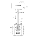
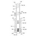
ここから本開示の好適な種々の実施形態を図示するための図面を参照することになり、図1には、低温流体源102から低温流体受け入れ構成要素114まで低温流体108を移送するための流体導管120の例が示されている。流体導管120の下部は、上流バルブ160、下流バルブ182、及び上流バルブ160と下流バルブ182との間を延びる熱伝達ゾーン152内に位置する加熱機構150を含む。以下により詳しく記載されるように、上流バルブ160、下流バルブ182、及び加熱機構150は、低温流体108が導管下流端128を出て低温流体受け入れ構成要素114内を流れる前に、熱伝達ゾーン152内で低温流体108を効率的に加熱する方法で、上流バルブ160、下流バルブ182、及び加熱機構150を制御するためのコントローラ200(図2)を含むシステム100の一部である。
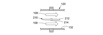
From here, reference is made to the drawings for illustrating various preferred embodiments of the present disclosure, in which FIG. 1 shows the fluid for transferring the
図1及び図2を参照すると、上流バルブ160、下流バルブ182、及び加熱機構150は、低温流体108の加熱中に熱伝達ゾーン152内の導管壁130に沿って形成される低温流体108の浮力流112からの熱損失を低減又は防止するように操作される。これに関し、加熱中に、導管内面132に最も近い低温流体108は、流体導管120の中心に向かって位置する低温流体108の下流移動主流110より温かい。導管内面132に対する低温流体108の加熱により、以下により詳しく記載されるように、低温流体108が、浮力流112と下流方向138に移動する低温流体108のより冷たい主流110との間の温度誘導による密度差に起因して上流方向136に移動する浮力流112に自然に分離するようになる。本開示のシステム100において有利には、上流バルブ160は、浮力流112が上流バルブ160を通過して移動するのを防止又は遮断し、これにより下流方向138に移動する低温流体108の主流110からの熱損失を低減又は遮断し、結果的に低温流体108が加熱される効率を高めるように操作される。
Referring to FIGS. 1 and 2, the
図1において、流体導管120は、導管上流端124で終端する上流部分122と、導管下流端128で終端する下流部分126と、導管内面132(図2)及び導管外面134(図2)を有する導管壁130とを有する。導管上流端124は、低温流体108を含む低温流体源102に流体連結されている。低温流体108は、沸点が比較的低い(例えば、120度K未満)任意の種類の流体を含みうる。幾つかの例では、低温流体108は、液体酸素(LOX)、液体水素(LH2)、液体メタン若しくは液化天然ガス(LNG)、又は打ち上げロケット300用のロケットエンジン310(図22)又は低温流体108を使用する任意の他の用途の低温推進剤として使用されうる、任意の他の種類の液化酸化剤及び/又は液化燃料などの液化ガスを含むがこれらに限定されない低温推進剤を含みうる。低温流体源102は、導管上流端124に連結されたタンク出口106(図22)を有する推進剤タンク304(図22)などの低温タンク104でありうる。
In FIG. 1, the
導管上流端124は、惑星体(例えば、地球)の重力などの加速力140、又は低温流体108を流体導管120を通って下流方向138に流す任意の他の種類の加速力140の下、流体導管120を通って流れる低温流体108を受ける。微小重力又はゼロ重力の環境における宇宙船の例では、加速力140は、流体導管120の下流方向138に一般に平行な方向に、宇宙船の一又は複数のスラスタ(図示されず)を点火することによって、生成されうる。スラスタは、宇宙船の主エンジンを始動させる前の期間に点火されうる。スラスタの点火により、低温流体108は、下流方向138に沿って流体導管120を通って流されうる。
The upstream end of the
流体導管120は、低温流体源102と低温流体受け入れ構成要素114との間で流体導管120の長さ方向に沿って、一又は複数の回転(turn)若しくは屈曲(bend)を有しうる。幾つかの例では、流体導管120の少なくとも一部は、加速力140の方向に一般に平行に配向されうる。幾つかの例では、流体導管120の少なくとも一部は、流体導管120の少なくとも一部が重力に平行であるという意味では、垂直に配向されうる(例えば、図22)。流体導管120は、加速力140(例えば、重力)の方向のおよそ80度の範囲に配向されうる。発射台上の垂直離陸打ち上げロケット300(例えば、図22)について、流体導管120の少なくとも一部は、およそ垂直に(例えば、±10度)、かつ水平よりおよそ10度以上に配向されうる。
The
打ち上げロケット300の例では、流体導管120は、低温推進剤を運ぶための推進剤供給ラインとして機能しうる。例えば、流体導管120は、酸化剤供給ライン又は燃料供給ラインでありうる。流体導管120は、円形の断面を有し、又は流体導管120の断面は、様々な非円形形状のうちの任意の1つを有し、様々なサイズの任意の1つで提供されうる。例えば、打ち上げロケット300において、LOX用の流体導管120は、およそ12インチ以上の内径を有し得る。流体導管120の直径は、打ち上げロケット300(図22)の例におけるロケットエンジン310などの下流低温流体受け入れ構成要素114の必要な質量流量により決定されうる。
In the example of the
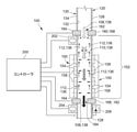
図2は、上流バルブ160、下流バルブ182、及び加熱機構150に通信可能に接続されたコントローラ200を含む本開示のシステム100を図示する、流体導管120の下部の拡大図である。加熱機構150は、流体導管120の熱伝達ゾーン152に位置し、低温流体108を加熱するように構成されており、熱伝達ゾーン152を通過する低温流体108の増加温度に対応する徐々に濃くなる矢印として図示されている。幾つかの例では、加熱機構150は、導管壁130を加熱し、結果的に導管内面132に直接隣接する低温流体108の層が、浮力流112に変換され、上記のように、上流方向136に移動する。低温流体108の残りの部分(即ち、主流110)は、熱伝達ゾーン152を通って、導管下流端128に向かって下流方向138に流れる。
FIG. 2 is an enlarged view of the lower part of the
図2では、加熱機構150は、流体導管120の熱伝達ゾーン152を通過する低温流体108を能動的に加熱するための一又は複数の動力加熱装置154として構成されうる。図2に示された動力加熱装置154は、熱伝達ゾーン152の導管外面134に関連付けられ、連結され、装着され、及び/又はその周囲に位置付けられうる。1つの例では、動力加熱装置154は、流体導管120周囲で周方向に間隔が空けられ、かつ熱伝達ゾーン152の縦方向部分に沿って間隔が空けられ、又は熱伝達装置は、上流バルブ160から下流バルブ182まで熱伝達ゾーン152の全長さに沿って間隔が空けられうる。加熱装置154の総量及び各加熱装置154の熱出力能力は、低温流体108の組成、流体導管120を通る低温流体108の最大質量流量、低温流体108が熱伝達ゾーン152に沿って通過するに際に、低温流体108の温度が上昇するに違いない量、及び他の要因に依存しうる。
In FIG. 2, the
1つの例では、加熱装置154は、導管外面134に巻かれた又は流体導管120を加熱するための導管壁130に組み込まれた一又は複数の抵抗線(図示されず)として提供されうる。別の例では、加熱装置154は、熱伝達ゾーン152に沿って導管外面134に締結された一又は複数の金属締結ヒータ(図示されず)として提供されうる。更に別の例では、加熱装置154は、赤外線加熱装置などの複数の放射加熱装置として提供されうる。放射加熱装置は、様々な構成のうちの任意の一又は複数の構成で提供されうる。1つの例では、加熱装置154は、核沸騰により低温流体108を加熱するように構成されうる。
In one example, the
図3では、熱伝達ゾーン152の外側のセクションで断熱材156で覆われた流体導管120の例が示される。流体導管120は、熱伝達ゾーン152内で断熱材156が低減されているか、断熱材156を有していないかである。断熱材156は、導管外面134を覆うポリマースプレー式発砲体などの発泡断熱材を含みうる。代替的には又は追加的には、断熱材156は、真空ジャケット、多層断熱材、及び/又は任意の他の種類の断熱材156でありうる。熱伝達ゾーン152内で、流体導管120は、断熱材156を少なくとも部分的に欠いている、及び/又は熱伝達ゾーン内の断熱材156は、断熱材156の厚さが低減されたため及び/又は断熱材156の断熱能力が低減されたために効率が低減しうる。熱伝達ゾーン152から断熱材156を低減又は省略することによって、受動加熱機構150が提供され、導管壁130の環境加熱159が可能になり、結果的に熱伝達ゾーン152を通過する低温流体108の伝導加熱がもたらされる。
FIG. 3 shows an example of a
なおも図3を参照すると、露出された流体導管120(例えば、非断熱)又は断熱材が低減された流体導管120の環境加熱159は、周囲空気加熱、太陽放射加熱、及び/又は熱伝達ゾーン152に近接して位置する構造からの放射加熱を含むがこれらに限定されない任意の数の環境加熱源(図示されず)によって提供されうる。例えば、放射加熱は、導管支持構造、タンク支持構造、ロケットエンジン310、及び/又は関連するエンジン構成要素によって放出されうる。断熱材156は、熱伝達ゾーン152の外側の断熱された流体導管120の環境加熱159の量に対して、熱伝達ゾーン152内の流体導管120の環境加熱159を増加させるように、熱伝達ゾーン152から局部的に低減されてもよく、又はまとめて省略されてもよい。図示されていないが、受動加熱機構150は、断熱材が低減されたか断熱材を含まない熱伝達ゾーン152が環境加熱159から遮蔽される遮蔽位置と、断熱材が低減されたか断熱材を含まない熱伝達ゾーン152が環境加熱159に露出される非遮蔽位置との間で熱遮蔽を移動させるためにコントローラ200によって制御されうる一又は複数の可動熱遮蔽をオプションで含みうる。
Still referring to FIG. 3, the environmental heating 159 of the exposed fluid conduit 120 (eg, non-insulated) or the
再び図2を参照すると、システム100は、加熱機構150のすぐ上流の流体導管120に連結又は統合される上流バルブ160を含む。上流バルブ160は、上流バルブ160を通って下流方向138に流れる低温流体108の上流バルブ質量流量を制御するために操作される。上流バルブ質量流量は、上流バルブ160を通って下流方向138に流れる低温流体108の上流バルブ非浮力質量流量から、上流バルブ160を通過して上流方向136に流れる任意の浮力流112の上流バルブ浮力質量流量を減算したものを含む。本開示のシステム100及び方法において、上流バルブ160は、浮力流112が上流バルブ160を通過して上流方向136に沿って移動するのを制限、低減、又は防止するように操作される。
Referring again to FIG. 2, the
加えて、システム100は、加熱機構150の下流に位置する下流バルブ182を含む。図1から図3に示される幾つかの実施形態において、下流バルブ182は、加熱機構150のすぐ下流の流体導管120に連結又は統合されうる。図示されない他の例では、下流バルブ182は、低温流体受け入れ構成要素114の一又は複数のバルブ、及び/又は低温流体受け入れ構成要素114の下流に位置する一又は複数のバルブを含みうる。例えば、低温流体受け入れ構成要素114が打ち上げロケット(図22)のロケットエンジン310(図22及び図23)である実施形態において、下流バルブ182は、エンジン310の一又は複数のバルブ(図示されず)、及び/又はロケットエンジン310の下流に位置する接地システム(図示されず)の一又は複数のバルブの組み合わせを含みうる。実施形態において、下流バルブ182は、接地システムのエンジンブリードシステムバルブ(図示されず)を含み、エンジン点火前に低温推進剤のエンジンブリード流を管理するように操作されうる。位置に関わらず、本開示のシステム100の下流バルブ182は、下流バルブ182を通って下流方向138に流れる低温流体108の下流バルブ質量流量を制御するように構成される。
In addition, the
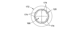
幾つかの例では、上流バルブ160及び/又は下流バルブ182は、可変開口バルブ164でありうる。可変開口バルブ164は、完全に開放された位置166、完全に閉鎖された位置170、及び完全に開放された位置166と完全に閉鎖された位置170との間の無限に多様な狭められた位置168(例えば、部分的に開放された位置)のうちの任意の1つ間で調節可能である。完全に開放された位置166では、低温流体108は、可変開口バルブ164を通してスムーズに流れる。完全に閉鎖された位置170では、低温流体108は、可変開口バルブ164を通しての流れが防止される。可変開口バルブ164のバルブ開口は、様々な異なる開口サイズ(例えば、開口幅又は有効な開口直径)の任意の1つに調節されると、流体導管120の断面中心に対して中心に置かれた状態を維持しうる。代替的には、図21に示され以下に記載される本開示のシステム100の別の例では、上流バルブ160は、完全に開放された位置166か完全に閉鎖された位置170のどちらかに移動可能である、又は狭められた位置168(例えば、部分的に開放された位置)に調節不能である開閉バルブ180でありうる。開閉バルブ180は、あまり複雑ではなく、したがって、可変開口バルブ164よりコストがかからず、動作が簡単でありうる。
In some examples, the
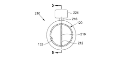
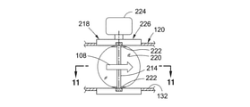
図4から図8は、可変開口バルブ164か開閉バルブ180かのどちらかとして操作されうるバタフライバルブ210として構成されるバルブ(例えば、上流バルブ160、下流バルブ182)の例を示す。図4は、バタフライバルブ210の直径方向に対向する側面の間を延びるシャフト214に連結されうるディスク212を含むバタフライバルブ210の断面図である。バタフライバルブ210は、シャフト214を回転させるためのアクチュエータ224を含みうる。ディスク212は、実質的に流体導管120の導管内面132の直径に相当するバルブ本体(図示されず)の内径に補完的にサイズ決定及び構成されうる。バタフライバルブ210が完全に閉鎖された位置170にある場合(図8)、ディスク212のエッジは、バルブ内面(図示されず)に対して密閉され、これにより低温流体108のバタフライバルブ210を通る流れが防止される。
4 to 8 show examples of valves configured as
図5は、完全に開放された位置166にあるバタフライバルブ210の側断面図であり、図示された例では円形を有するディスク212の外形が示されている。シャフト214は、流体導管120の直径方向に対向する側面に位置する一対の軸受によって支持されうる。図6は、一般に、低温流体108がバタフライバルブ210を通って無制限に流れることができるようにする、完全に開放された位置166にあるバタフライバルブ210を示す。図7は、狭められた位置168にあるバタフライバルブ210を示しており、ディスク212は、バタフライバルブ210の軸に対して非平行かつ非垂直に配向されており、これにより、バタフライバルブ210を通る低温流体108の流れが少なくとも部分的に遮断される。図8は、完全に閉鎖された位置170にあるバタフライバルブ210を示し、ここではバタフライバルブ210を通る低温流体108の流れが完全に遮断されている。アクチュエータ224は、シャフト214を旋回軸216周囲で回転させ、完全に開放された位置166、完全に閉鎖された位置170、又は無限に多様な狭められた位置168の任意の1つの間でディスク212の配向を変更するようコントローラによって命令されうる。
FIG. 5 is a side sectional view of the
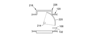
図9から図13は、可変開口バルブ164か開閉バルブ180かのどちらかとして操作されうるバイザーバルブ218として構成されるバルブ(例えば、上流バルブ160、下流バルブ182)の例を示す。図9は、バイザー要素220を含みうるバイザーバルブ218の断面図である。一対のバイザー装着アーム222は、バイザー要素220を、バイザーバルブ218の直径にわたって延びるシャフト214に連結させうる。バイザーバルブ218は、コントローラ200からの命令に応じて、バイザー要素220の配向を変更するためにシャフト214を回転させるためのアクチュエータ224を更に含みうる。これについて、バイザー要素220は、完全に開放された位置166、完全に閉鎖された位置170、又は無限に多様な狭められた位置168の任意の1つの間を移動し得る。
9 to 13 show examples of valves configured as
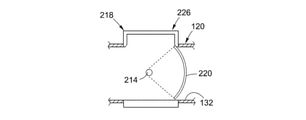
図10は、完全に開放された位置166にあるバイザーバルブ218の側断面図であり、シャフト214に装着されたバイザー要素220を更に示している。図11は、アーチ形のバイザー要素220の例を示すバイザーバルブ218の上断面図である。バイザー要素220が完全に開放された位置166にあるとき、バイザー要素220は、回転してバルブハウジング226の空洞に入り、低温流体108は、バイザーバルブ218を通って無制限に流れることができるようになる。図12は、狭められた位置168にあるバイザーバルブ218を示し、この場合、バイザーバルブ218を通る低温流体108の流れは、部分的に防止又は遮断されている。図13は、完全に閉鎖された位置170にあるバイザーバルブ218を示しており、この場合、バイザー要素220は、低温流体108のバイザーバルブ218を通る流れを防止するように、バイザーバルブ218に密閉されている。
FIG. 10 is a side sectional view of the
図4から図13は、様々なバルブ構成の任意の1つについての2つの例を示しており、その中で、バルブ開口は、狭められた位置168(例えば、部分的に開放された位置)にあるときには中心に置かれておらず、狭められた位置168に対するサイズ及びバルブ開口の調節中に中心に置かれていない状態が維持される。例えば、図4から図8に示される上記バタフライバルブ210は、ディスク212が図7に示されるように狭められた位置168にあるとき、ディスク212の直径方向に対向する側面に開口を提供する。同様に、図9から図13に示される上記バイザーバルブ218は、バイザー要素220が図12に示されるように狭められた位置168にあるとき、中心に置かれていない開口を有する。しかしながら、上流バルブ160の中心に置かれていない開口は、浮力流112の少なくとも一部を防止又は遮断しうる。例えば、バタフライバルブ210又はバイザーバルブ218が狭められた位置168にあるとき、ディスク212(図7)又はバイザー要素220(図12)のそれぞれの少なくとも一部は、バルブ内面(図示されず)に近接するか直接的に接触し、これにより、周囲に位置する浮力流112の少なくとも一部を遮断しうる。これに関し、中心に置かれていない開口は、浮力流112を直接、物理的に遮断することはないが、狭められた位置168は、結果的に上流バルブ160を通して断面流面積を低減し、上流バルブ160を通って下流方向138に移動する速度の増した低温流体108が、周囲に位置する浮力流112と混合又は相互作用し、これによって浮力流112が上流バルブ160の上流を通過するのを克服及び/又は防止する点まで、低温流体108の速度を増加させうる。
4 to 13 show two examples for any one of the various valve configurations, in which the valve opening is in a narrowed position 168 (eg, a partially open position). When in, it is not centered and remains uncentered during size and valve opening adjustments for the narrowed
図14から図16は、可変開口バルブ164か開閉バルブ180かのどちらかとして操作されうるアイリスダイヤフラムバルブ172として構成された可変開口バルブ164の例を示す。図示された例において、アイリスダイヤフラムバルブ172は、流体導管120の導管軸(図示されず)に対して横に配向された平面(図示されず)内で各々が旋回可能である一組の重なるリーフ174を有している。図14は、完全に開放された位置166にあるアイリスダイヤフラムバルブ172を示す。図15は、狭められた位置168(例えば、部分的に開放された位置)にあるアイリスダイヤフラムバルブ172を示す。図16は、完全に閉鎖された位置170にあるアイリスダイヤフラムバルブ172を示す。アイリスダイヤフラムバルブ172が、コントローラ200によってバルブ開口のサイズを変更するように命令されると、アイリスダイヤフラムバルブ172のリーフ174は、同じ量だけ各々が旋回し、よってバルブ開口は、有利には、バルブ開口のサイズに関わらず、流体導管120の断面中心に対して中心に置かれた状態を維持する。
14 to 16 show an example of a
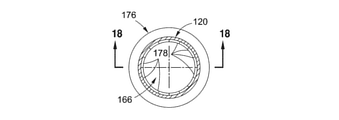
図17から図19は、また可変開口バルブ164か開閉バルブ180かのどちらかとして操作されうる可変開口ノズル176として構成された可変開口バルブ164の例を示す。図示された例では、可変開口ノズル176は、流体導管120の導管軸に対して横に配向された平面に入射する軸周囲を各々が旋回可能である一組の重なるペタル178を有している。図17は、完全に開放された位置166にある可変開口ノズル176を示す。図18は、完全に開放された位置166にある可変開口ノズル176の側断面図である。図19は、狭められた位置168にある可変開口ノズル176を示す。図20は、狭められた位置168にある可変開口ノズル176の側断面図である。可変開口ノズル176が、コントローラ200によってバルブ開口のサイズを変更するように命令されると、可変開口ノズル176のペタル178は、同じ量だけ各々が旋回し、よってバルブ開口は、有利には、バルブ開口のサイズに関わらず、導管の断面中心に対して中心に置かれた状態を維持する。
17 to 19 also show an example of a
図14から図20は、バルブ開口が、バルブ開口のサイズに関わらず、流体導管120内で中心に置かれた状態を維持する様々なバルブ構成の2つの例を示す。上流バルブ160が狭められた位置168にあるとき、上流バルブ開口162を中心に維持することにより、上流バルブ160を通る低温流体108の流れが流体導管120内で中心に置かれる一方で、上流バルブ160は、同時に、周辺に位置する浮力流112の上流バルブ160を通過して上流方向136への移動を防止又は遮断し、これにより、熱伝達ゾーン152内の低温流体108からの熱損失を回避し、加熱機構150の加熱効率を高める。
14-20 show two examples of various valve configurations in which the valve opening remains centered within the
図2を再び参照すると、システム100は、上流バルブ160、下流バルブ182に通信可能に接続され、加えて加熱機構150に通信可能に接続されうるコントローラ200を含む。コントローラ200は、人が介入又は監視することなく、上流バルブ160、下流バルブ182、及び加熱機構150を制御するように構成されたコンピュータシステム(例えば、地上ベース又は車両ベース)の一部でありうる。実施形態では、コントローラ200は、上流バルブ160を狭められた位置168に調節するように構成されており、狭められた位置で、(1)上流バルブ非浮力質量流量は、下流バルブ質量流量と実質的に一致し、(2)上流バルブ160は、浮力流112が上流バルブ160を通過して上流方向136に流れるのを少なくとも部分的に防止、遮断、又は阻止する。狭められた位置168の上流バルブ160による浮力流112の部分的遮断は、上流バルブ160が存在しなければ、熱伝達ゾーン152から外へ、可能であれば導管上流端124から外へ流れるだろう浮力流112の量に対して、上流バルブ160を通過して熱伝達ゾーン152から外へ移動する浮力流112の量を低減すること(例えば、少なくとも50パーセント)を含みうる。上記のように、狭められた位置168の上流バルブ160は、有利には、浮力流112が、低温流体108の加熱された主流110の一部を上流バルブ160を通過して上流方向136に引き寄せるのを低減又は防止し、不所望にも、加熱機構150の加熱効率を低減することになるだろう。
Referring again to FIG. 2, the
図2及び図3を参照すると、システム100は、上流の流量計202、下流の流量計204、及び/又は温度センサ206を含みうる。上流の流量計202は、上流バルブ160の上流バルブ開口162を通って下流方向138を通過する低温流体108の上流バルブ非浮力質量流量を測定するように構成されうる。下流の流量計204は、下流バルブ182の下流バルブ開口184を通って下流方向138を通過する低温流体108の下流バルブ質量流量を測定するように構成されうる。上流の流量計202及び/又は下流の流量計204は、ベンチュリ流量計、タービン流量計、超音波流量計、差圧流量計、又は様々な他の種類の質量流量計のうちの任意のものとして構成されうる。
With reference to FIGS. 2 and 3, the
コントローラ200は、低温流体108の上流バルブ質量流量及び下流バルブ質量流量それぞれを示す上流の流量計202及び下流の流量計204からデータを受信しうる。上記のように、下流バルブ質量流量は、下流バルブ182を通過する低温流体108の質量流量を示しうる。代替的には、下流バルブ質量流量は、導管下流端128から出る低温流体108の質量流量、又は下流バルブ182と導管下流端128との間の流体導管120の下流部分126の任意の位置における低温流体108の質量流量を示しうる。更なる実施形態では、下流バルブ質量流量は、導管下流端128の下流の任意の位置を含む、下流バルブ182の下流の任意の位置における低温流体108の質量流量を示しうる。下流バルブ質量流量を示すデータの受信に応じて、コントローラ200は、上流バルブ160が存在しなければ、導管上流端124から外へ(例えば、同伴主流110と共に)流れるだろう浮力流112に対して、上流バルブ160を通過して浮力流112の移動が防止されるように、上流バルブ160を(例えば、狭められた位置168に)自動的に(例えば、人が介入せずに)調節しうる。
The
これに関し、コントローラ200は、完全に開放された位置166から、低温流体108の最初の低い質量流量の部分的に開放された位置と説明される狭められた位置168まで、上流バルブ開口162のサイズを最初に調節しうる。以下でより詳しく記載される打ち上げロケット300(図22及び図23)の例では、外部システム(図示されず)からの命令に応じて、コントローラ200は、エンジン始動ボックス要件に基づき、上流バルブ開口162及び下流バルブ開口184のサイズを調節しうる。以下に記載されるように、実際の低温流体温度がエンジン始動ボックス要件毎に所望の低温流体温度まで加熱されるとき、下流バルブ182及び上流バルブ160は各々、低温流体108のロケットエンジン310への質量流量増加を促進するために、狭められた位置168から完全に開放された位置166まで移動する。上流バルブ160及び下流バルブ182が完全に開放された位置166にあると、最初に低い質量流量下の浮力流112により上流に引き寄せられるだろう任意の温められた低温流体108は、増加した質量流量下の下流移動低温流体108と同伴又は混合されるようになり、よって上流バルブ160を狭められた位置168に維持し、浮力流112を遮断することは、もはや不要となる。
In this regard, the
温度センサ206は、下流バルブ182又は導管下流端128などの流体導管120の下流部分126で、低温流体108の実際の低温流体温度を測定するように構成されうる。温度センサ206は、低温流体108の実際の低温流体温度を測定し、実際の低温流体温度を示すデータをコントローラ200に送信することができるように、流体導管120に装着、連結、配置、又は関連付けられうる。コントローラ200は、実際の低温流体温度を示すデータを受信し、温度データに基づき、実際の低温流体温度を、実質的に所望の低温流体温度の所定の範囲内(例えば、20%以内)に維持するように、加熱機構150の熱158出力を制御するように構成される。ロケットエンジン310の例では、実際の低温流体温度が、エンジン始動ボックス要件毎に、所望の低温流体温度の所望の範囲(例えば、±2度R)内に維持されるように、コントローラ200は、加熱機構150の熱158出力を調節するよう構成されうる。始動ボックス要件は、エンジン始動用推進剤の温度及び圧力の範囲(例えば、最大値及び最小値)として記載されうる。
The
代替的には、加熱機構150が断熱材156(図3)が低減されたり断熱材156を含まない熱伝達ゾーン152の流体導管120の縦方向セクションの環境加熱159(図3)を含む場合のシステム100の構成について、コントローラ200は、上流バルブ160を狭められた位置168に調節し、結果的に、環境加熱159が、実際の低温流体温度を実質的に所望の低温流体温度に維持できるようにする上流バルブ質量流量をもたらす。例えば、実際の低温流体温度(例えば、温度センサ206により測定される)が所望の低温流体温度より上昇する場合、コントローラ200は、より多くの浮力流112が、上流バルブ160を通過して上流方向136に逃げられるような効果を有する上流バルブ開口162のサイズを増加させ、下流方向138の低温流体108に混合される熱量を低下させ、よって温度センサ206により測定される低温流体108の温度を低下させうる。逆に、実際の低温流体温度が所望の低温流体温度より下降する場合、コントローラ200は、上流バルブ160を通過して上流方向136に逃げる浮力流112の量を低下させる効果を有する上流バルブ開口162のサイズを縮小し、下流方向138の低温流体108に混合される熱量を増加させ、よって温度センサ206により測定される低温流体108の温度を増加させうる。
Alternatively, if the
図2を参照すると、上記のように、コントローラ200は、下流バルブ182を自動的に制御し、低温流体108の所望の下流バルブ質量流量を満たし、熱伝達ゾーン152を通って低温流体108の速度を結果的に増加させる狭められた位置168に、下流バルブ開口184のサイズを調節する(例えば、縮小する)ように構成されうる。加えて、上流バルブ160は、低温流体108を一般に中心に置かれた主流110として熱伝達ゾーン152内に及び/又は熱伝達ゾーン152を通って流す、中心に位置する上流バルブ開口162を有する可変開口バルブ164でありうる。一般に中心に位置する主流110の増加速度により、周囲に位置しゆっくり移動する浮力流112は、主流110内に同伴又は混合されるようになり、低温流体108の温度を増加させ、これにより、加熱機構150が低温流体108を加熱する効率が高まりうる。増加した熱効率により、コントローラ200は、加熱機構150の熱158出力を低減することができ、及び/又は加熱装置154の量及び/又は熱出力定格(heat−output−rating)を低減することができる。
Referring to FIG. 2, as described above, the
所望の低温流体温度(例えば、ロケットエンジン310のエンジンインターフェース312での始動ボックス温度)にいったん到達すると、コントローラ200が、流量を増加するよう命令されると(例えば、事前のプログラミングを介して、又は外部命令システムからの手動命令を介して)、コントローラ200は、加熱機構150を動作停止し、下流バルブ182及び上流バルブ160を完全に開放された位置166に調節しうる。加熱機構150が動作停止されるため、かつ流量が増加するため、そうでなければその代わりに浮力流112内に向きを変えるだろう任意の温かい低温流体108は、下流方向138に移動するより速く移動している主流110内に同伴されるようになり、よって上流バルブ160が浮力流112の流れを遮断することは、もはや不要になる。上流バルブ160及び下流バルブ182は、完全に開放された位置166に移動し、低温流体108がロケットエンジン310に完全に流れるようにする一方で、加熱機構150は、動作が停止された状態を維持するか、又は低温流体108に熱158がほとんど又は全く印加されないように操作される。
Once the desired cold fluid temperature (eg, the starting box temperature at the
図21は、本開示のシステム100の例の概略図であり、流体導管120は、上流バルブ160に平行に配置されたバイパスレッグ190に装着されたバイパスバルブ196を含む。バイパスレッグ190は、バイパスレッグ上流端192及びバイパスレッグ下流端194を有している。バイパスレッグ上流端192は、上流バルブ160のすぐ上流の位置で、流体導管120に流体連通されている。バイパスレッグ下流端194は、上流バルブ160のすぐ下流の位置で、流体導管120に流体連通されている。上流バルブ160及び/又はバイパスレッグ190は、完全に開放された位置166か完全に閉鎖された位置170かのどちらかに移動可能であり、狭められた位置168に対して調節不能である開閉バルブ180として構成されうる。上記のように、開閉バルブ180は、あまり複雑ではなく、したがって、可変開口バルブ164よりコストがかからず、動作が簡単でありうる。代替的には、上流バルブ160及び/又はバイパスバルブ196は、開閉バルブ180として操作される可変開口バルブ164として提供され、可変開口バルブ164は、完全に開放された位置166か完全に閉鎖された位置170かのどちらかに移動可能である。
FIG. 21 is a schematic representation of an example of the
図21のシステム100の実施形態では、コントローラ200は、下流バルブ質量流量を示すデータを受信し、上流バルブ160を完全に閉鎖された位置170に自動的に調節し、バイパスバルブ196を完全に開放された位置166に調節し、上流バルブ160の上流の低温流体108をバイパスレッグ190内に迂回させ、上流バルブ160のすぐ下流の流体導管120に再び流れ込むようにする。有利には、完全に閉鎖された上流バルブ160は、熱伝達ゾーン152内に形成される任意の浮力流112にバリアを形成し、これにより、そうでなければ、浮力流112が上流バルブ160を通過して移動することができた場合に発生するだろう熱損失を防止する。
In the embodiment of
図21では、幾つかの実施例において、バイパスレッグ190は、最初の低い質量流に対して必要な下流バルブ質量流量を補完するようにサイズ決定される断面積を有しうる。例えば、以下に記載される打ち上げロケット300(図22及び図23)の例では、バイパスレッグ190の断面積は、エンジン始動前にエンジンの熱的調整に対して必要な下流バルブ質量流量に基づいてもよい。エンジン点火の直前に、バイパスバルブ196は完全に閉鎖された位置170に移動し、下流バルブ182及び上流バルブ160は、完全に開放された位置166に移動し、質量流量の増加が促進され、低温促進剤をロケットエンジン310に完全に流すことができる。上流バルブ160及び下流バルブ182が完全に開放された位置166にあり、低温流体108が増加した質量流量で流れている際に、そうでなければ最初に低い質量流量下で上流に移動するだろう任意の温められた低温流体108は、ここで速度が増加した下流に移動する低温流体108と混合され、よって浮力流112を遮断する目的で上流バルブ160を閉鎖位置に維持することは、もはや不要である。
In FIG. 21, in some embodiments, the
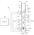
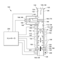
図22は、ペイロード302を地球周回軌道などの宇宙に打ち上げるための打ち上げロケット300の例を示す。打ち上げロケット300は、燃焼チャンバ314及びエンジンノズル316を有する液体推進剤ロケットエンジン310を含むエンジンセクションを有している。加えて、打ち上げロケット300は、燃料タンク308及び酸化剤タンク306を含む一対の低温推進剤タンク304を有している。燃料タンク308は、液体水素(LH2)などの低温燃料を包含しうる。酸化剤タンク306は、液体酸素(LOX)などの酸化剤を包含しうる。流体導管120は、酸化剤タンク306をロケットエンジン310のエンジンセクションに流体連通させ、別の流体導管120は、燃料タンク308をロケットエンジン310のエンジンセクションに流体連通させる。
FIG. 22 shows an example of a
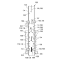
図23には、上流バルブ160と熱伝達ゾーン152内に位置する加熱機構150とを含む流体導管120の各々の下流部分126が示されている。図23は、加熱機構150のすぐ下流の流体導管に装着された下流バルブ182を示しているが、下流バルブ182は、導管下流端128の下流に位置する一又は複数のバルブ(図示されず)を含みうる。例えば、下流バルブ182は、上記のように、ロケットエンジン310のバルブ(図示されず)、及び/又は接地システムのエンジンブリードシステムバルブ(図示されず)などのロケットエンジン310の下流に位置する一又は複数のバルブ(図示されず)の組み合わせを含みうる。
FIG. 23 shows each
図23の例では、各流体導管120の下流部分126は、ロケットエンジン310のエンジンセクションに流体連通されている。例えば、導管下流端128は、ターボポンプなどのポンプ(図示されず)、燃焼チャンバ314若しくは事前燃焼チャンバ、又は別のエンジン構成要素に流体連通されうる。加熱機構150は、低温流体108が熱伝達ゾーン152を通って流れる際に、低温流体108(例えば、LH2、LOX)を加熱するように構成される。例えば、酸化剤タンク306から流れるLOXは、最初に163Rの温度でエンジンセクションに流入し、2lbm/sのエンジンブリード質量流量で流れうる。しかしながら、エンジン始動ボックス要件は、LOXが168Rの温度でエンジンセクションに流入することを必要とする。163Rから168Rまでの5RだけLOXの温度を増加させるために、5BTU/sの熱をLOXに印加しなければならない。熱158は、熱伝達ゾーン152に沿って位置する外部の加熱装置154を使用して印加されうる。加熱装置154は、エンジン始動前に一定期間(例えば、およそ1時間)作動しうる。
In the example of FIG. 23, the
加熱装置154が熱伝達ゾーン152内の導管内面132と接触するLOXの層を温めると、LOXの温められた層は、浮力流112として上流に移動する傾向がある。加熱されたLOXの残りの部分又は主流110は、エンジンブリード流に起因し、エンジンセクション内に引き下げられる。浮力流112のため主流110からの熱損失を防止することなく、加熱装置154は、加熱装置154の電力(power)によって分割されるエンジンブリード質量流量の比率に基づき、約20〜80%の加熱非効率を有し得る。5RだけLOXの温度を増加させるために5BTU/sが必要とされる上記例について、20〜80パーセントの加熱非効率は、流体導管120に印加しなければならない6.25〜25BTU/sの総電力に相当する。言い換えれば、そうでなければ、浮力流112のため熱損失が存在しなかった場合に必要とされるだろうよりも1.25〜5倍多い電力が、LOXを加熱するのに必要とされる。上記のように、浮力流112に起因する熱損失により、不所望にも、酸化剤タンク306のバルクLOXの密度を低下させることもあり、結果的に、打ち上げロケット300に対して利用可能な推進剤質量を低下させ、軌道内に打ち上げることができるペイロード302の量もそれに応じて低下する。
When the
有利には、本開示のシステム100は、加熱機構150のすぐ上流に位置する上流バルブ160を使用して浮力流112を遮断することによって、LOXからの熱損失を低減又は防止する。例えば、本開示のシステム100は、各々が最初に完全に開放された位置166にある、上流バルブ160及び下流バルブ182を含む。LOXの加熱を開始するために加熱装置154を作動させると、コントローラ200はまた、下流バルブ182に、完全に開放された位置166から、エンジンブリード質量流量に対応する狭められた位置168まで移動するように命令する。加えて、コントローラ200は、上流バルブ160に、完全に開放された位置166から、上流バルブ非浮力質量流量が下流バルブ質量流量に実質的に一致する(例えば、30パーセント以内)狭められた位置168まで移動するように命令する。
Advantageously, the
上流バルブ160を狭められた位置168に調節することにより、上流バルブ160を通って流れるLOXの速度を増加させる。LOXの速度増加により、浮力流112が上流バルブ160を通過して移動するのを低減又は防止し、加熱装置154の加熱効率が著しく高められる。加えて、部分的に開放された上流バルブ160の下面は、浮力流112の少なくとも一部の上流への移動を防止又は遮断しうる。質量流量が許容される例では、上流バルブ160は、上記例において、加熱効率を1.25〜5倍ほど増加させるだろうすべての浮力流112を完全に遮断する狭められた位置168に調節されうる。更に、環境源からのLOXの加熱(例えば、近接する構成要素からの放射加熱)は、そうでなければ浮力流112のため失われるのだが、熱伝達ゾーン152内で捕捉され、加熱効率を更に高めるだろう。加熱効率の全体的な向上により、加熱装置154の電力出力が低下することで、LOXの5Rの温度増加が実現可能となり、同一の電力出力を使用する加熱装置154は僅かである。
Adjusting the
図24、加えて図25から図27を参照すると、流体導管120を通って流れる低温流体108を加熱する効率を高める方法400に含まれうる一又は複数の工程を有するフローチャートが図24に示される。方法400は、ロケット打ち上げの用途(例えば、図22及び図23)に照らして、より具体的には、コントローラ200(例えば、図2)、上流バルブ160、下流バルブ182、及び上流バルブ160と下流バルブ182との間の熱伝達ゾーン152内に位置する加熱機構150を含む本開示のシステム100を使用してロケットエンジン310を始動させる準備に向け、低温流体108(例えば、低温酸化剤又は低温燃料)を加熱することに照らして、説明される。図25は、複数の動力加熱装置154から成る加熱機構150の例を示す。図24の方法400において、上流バルブ160(図25)は、最初は完全に開放された位置166にありうる。下流バルブ182(図25)は、コントローラ200によって、下流バルブ182を通る低温流体108の所望の下流バルブ質量流量を満たす狭められた位置168に自動的に調節されうる。幾つかの例では、コントローラ200は、事前にプログラムされた打ち上げ手順の打ち上げ段階に基づき、下流バルブ182を調節しうる。他の例では、コントローラ200は、下流バルブ182を狭められた位置168に調節するように手動で命令されてもよい。下流バルブ182の狭められた位置168は、下流バルブ質量流量が実質的にエンジンブリード流に相当するようなものであってもよい。加熱機構150(図25)は、加熱機構150によって熱伝達ゾーン152を通過する低温流体108に、熱158がほとんど又は全く供給されないような状態(例えば、動作停止状態)にあってもよい。
With reference to FIG. 24, plus FIGS. 25-27, FIG. 24 shows a flow chart having one or more steps that may be included in
方法400のステップ402は、流体導管120において、低温推進剤タンク304などの低温流体源102に流体連結された導管上流端124で、低温流体108を受けることを含む。図25に示されるように、低温流体108は、加速力140(例えば、重力)下で、流体導管120を通り、導管下流端128に向かって下流方向138に、ロケットエンジン310(図23)のエンジンセクションなどの低温流体受け入れ構成要素114に流入する。
Step 402 of the
方法400のステップ404は、熱伝達ゾーン152内に位置する加熱機構150を使用して、低温流体108を加熱することを含む。低温流体108を加熱することは、上記のように、流体導管120に近接して装着又は配置される一又は複数の動力加熱装置154を使用して、低温流体108を加熱することを含みうる。図26は、流体導管120の導管壁130に熱158を放出、放射、又は印加し、結果的に低温流体108を加熱する複数の加熱装置154を示す。しかしながら、能動加熱の代わりに又はそれに加えて、低温流体108の加熱は、放射加熱、周囲空気加熱、又は任意の他の種類の受動加熱を含む環境加熱159を使用して、受動的に実行されてもよい。例えば、上記のように、熱伝達ゾーン152に沿った導管外面134の受動的加熱は、熱伝達ゾーン152内の導管外面134で断熱材156が低減されるか存在しないために起こりうる。熱伝達ゾーン152の外側の流体導管120の残りの部分は、上流バルブ160の上流の低温流体108の環境加熱159を低減又は防止するために、断熱材156によって少なくとも部分的に覆われ、これにより上流バルブ160の上流での浮力流112の発生が低減又は防止される。
Step 404 of the
方法400のステップ406は、熱伝達ゾーン152内で低温流体108を加熱した結果として、熱伝達ゾーン152内において、低温流体108の一部を浮力流112に変換することを含む。図26は、上記のように、導管内面132に極隣接した低温流体108加熱のため、熱伝達ゾーン152内の導管壁130の導管内面132に沿って自然に形成される浮力流112を示す。流体導管120の中心に最も近い低温流体108の冷たい主流110の密度に対して温かい浮力流112の密度が低下するため、浮力流112は、導管内面132に沿って、上流バルブ160に向かって上流方向136に移動する。低温流体108の主流110は、導管下流端128に向かって下流方向138に移動する。
Step 406 of
方法400のステップ408は、コントローラ200を使用して、上流バルブ160を通る低温流体108の上流バルブ非浮力質量流量が下流バルブ182を通る低温流体108の下流バルブ質量流量と実質的に一致する狭められた位置168に、上流バルブ160を調節することを含む。図25から図27において、上流バルブ160及び下流バルブ182は各々、完全に開放された位置166、完全に閉鎖された位置170、及び狭められた位置168(例えば、図26)の間で調節可能な上流バルブ開口162並びに下流バルブ開口184それぞれを有する可変開口バルブ164として構成される。コントローラ200は、加熱機構150の起動又は電源入力と実質的に同時に、又は加熱機構150の起動前後数分以内に、上流バルブ160を狭められた位置168に調節するようプログラムされうる。
Step 408 of
方法400は、加えて、上流の流量計202及び下流の流量計204を使用して、上流バルブ160の上流バルブ開口162及び下流バルブ182の下流バルブ開口184それぞれを通って下流方向138に流れる低温流体108の上流バルブ質量流量及び下流バルブ質量流量それぞれを測定することを含みうる。上記のように、上流バルブ非浮力質量流量が下流バルブ質量流量と実質的に一致し、狭められた位置168の上流バルブ160により、結果的に、浮力流112の少なくとも一部が、上流バルブ160を通過して上流方向136に流れるのを遮断するために、上流の流量計202及び下流の流量計204は各々、上流バルブ質量流量及び下流バルブ質量流量を示すデータを、上流バルブ開口162のサイズを調節するためにそのデータを使用するコントローラ200に送信する。
方法400のステップ410は、低温流体108の主流110が、下流方向138に、狭められた上流バルブ160を通って熱伝達ゾーン152に流入する間、浮力流112の少なくとも一部が上流バルブ160を通過して上流方向136に移動するのを、上流バルブ160を使用して防止、阻止、又は遮断することを含む。図26は、加熱装置154が熱158を低温流体108に印加し続ける間、浮力流112を少なくとも部分的に遮断する上流バルブ160を示す。方法400は、狭められた上流バルブ160の環状下流側(図示されず)が浮力流112を少なくとも部分的に遮断するように、上流バルブ開口162が流体導管120内で中心に置かれた状態を維持することを含みうる。加えて、狭められた位置168にある上流バルブ160を通過する低温流体108は、上流バルブ160が完全に開放された位置にあるときの低温流体108の速度に対して増加した速度で移動することがある。低温流体108の速度が増加することにより、温かい浮力流112の、熱伝達ゾーンに流入する冷たい低温流体108への同伴又は混合を促進し、浮力流112が180度方向変換し、低温流体108を加熱するだけではなく、下流方向138に沿って流れ始めることがある。幾つかの例では、コントローラ200は、閉ループ式に動作し、上流の流量計202及び下流の流量計204それぞれから、上流バルブ質量流量及び下流バルブ質量流量を示すデータを継続的に受信し、上流バルブ非浮力質量流量が実質的に下流バルブ質量流量に相当するように、上流バルブ開口162のサイズを継続的に調節する。
In
方法400は、加えて、温度センサ206を使用して、低温流体108の実際の低温流体温度を監視又は測定することを含みうる。例えば、温度センサ206は、下流バルブ182のすぐ下流、又は導管下流端128における実際の低温流体温度を測定するように構成されうる。温度センサ206は、実際の低温流体温度を示すデータをコントローラ200に送信しうる。コントローラ200は、実際の低温流体温度を示すデータを受信し、所望の低温流体温度に達するまで低温流体108の温度を増加させるように、加熱機構150の熱158出力を制御しうる。所望の低温流体温度は、低温流体108のエンジン始動温度であってもよい。低温流体108が所望の低温流体温度に到達すると、コントローラ200は、温度センサ206から温度データを受信し続け、実際の低温流体温度が、実質的に所望の低温流体温度(例えば、±R以内)における温度に維持されるように、コントローラが、加熱機構150を管理し、加熱機構150の熱158出力を調節することができるようになる。代替的には、加熱機構150が、加熱装置154(図2)を使用した能動的加熱とは対照的に、流体導管120の環境加熱159(図3)を含む上記システム100の構成について、上流バルブ質量流量によって、環境加熱159が、実際の低温流体温度を実質的に所望の低温流体温度(例えば、20%以内)に維持できるように、コントローラ200が、上流バルブ160の狭められた位置168を調節しうる。
ロケットエンジン310の例では、低温流体108がターゲットエンジン始動温度に達すると、ロケットエンジン310が始動し、コントローラ200は、熱158の出力を停止するために、加熱機構150の動作を停止しうる。加えて、コントローラ200は、エンジンへの低温流体108の増加した又は全ての質量流量を収容するために、上流バルブ160及び下流バルブ182を完全に開放された位置166まで移動させうる。図27は、低温流体108が所望の下流低温流体温度に達すると動作が停止する加熱機構150、更には完全に開放された位置166に調節され、低温流体108の質量流量の増加を実現する、上流バルブ160及び下流バルブ182を示す、図25の流体導管120の概略図である。
In the example of the
図18から図20は、図21を参照して先ほど説明された、バイパスバルブ196を有するシステム100の実施形態の工程を示す。図28は、低温流体108が流体導管120で受けられ、加熱機構150の作動前にオプションで存在しうる上記ステップ402に類似した、最初に完全に閉鎖された位置170にあるバイパスバルブ196、完全に開放された位置166にある上流バルブ160、及び狭められた位置168にある下流バルブ182を示す。上流バルブ160及び/又はバイパスレッグ190は、完全に開放された位置166か完全に閉鎖された位置170かのどちらかに移動可能であり、狭められた位置168に対して調節不能である上記開閉バルブ180として構成されうる。しかしながら、上流バルブ160、下流バルブ182、及び/又はバイパスバルブ196は、完全に開閉された位置166と完全に閉鎖された位置170との間で移動可能である、開閉バルブ180として操作される可変開口バルブ164として提供されうる。
18 to 20 show the steps of the embodiment of the
図29は、完全に開放された位置166にあるバイパスバルブ196、及び完全に閉鎖された位置170にある上流バルブ160を示す。加熱機構150の作動と同時に又はそれよりわずか前後に(例えば、数分以内に)、完全に開放された位置166にあるバイパスレッグ190及びバイパスバルブ196が、狭められた位置168の下流バルブ開口184の断面積と実質的に一致する断面積を有し、よってバイパスバルブ196の開口サイズを調節する必要がなくなることを除き、上記ステップ408と類似した工程において、コントローラ200は、バイパスバルブ196を完全に開放された位置166に移動させ、上流バルブ160を完全に閉鎖された位置170に移動させるようプログラムされうる。そのような配置において、方法は、上流バルブ160を閉鎖して、浮力流112が上流バルブ160を通過して移動するのを遮断し、バイパスバルブ196を開放するためにコントローラ200を使用することと、これにより、低温流体108をバイパスレッグ190を通って熱伝達ゾーン152内に送ることとを含みうる。加熱機構150は、低温流体108の加熱を引き起こす上記ステップ404に類似した方法で作動され、上記ステップ406に類似した方法で、結果的に低温流体108の一部を浮力流112に変換する。上記ステップ410同様に、上流バルブ160の閉鎖により、浮力流112が上流バルブ160を通過して移動するのを遮断し、結果的に、バイパスレッグ190から熱伝達ゾーン152に流入する低温流体と混合される浮力流112が遮断されうる。
FIG. 29 shows a
方法は、温度センサ206の位置次第で、下流バルブ182又は導管下流端128で実際の低温流体温度を監視することと、温度データをコントローラ200に送信することとを含みうる。上記のように、低温流体108が、加熱機構150によって印加される熱から所望の低温流体温度にいったん達すると、エンジンが始動され、その時点で、コントローラ200が、加熱機構150の動作を停止し、バイパスバルブ196を完全に閉鎖された位置170に移動させ、図30に示されるように、上流バルブ160及び下流バルブ182の両方を完全に開放された位置166に移動させ、低温流体108の増加した質量流量を収容し、これにより低温流体108(例えば、低温酸化剤、低温燃料)のすべてをエンジン310に流すことが可能になる。
The method may include monitoring the actual cold fluid temperature with a
更に、本開示は下記の条項による実施形態を含む。
条項1. 低温流体を加熱するためのシステムであって、
導管上流端及び導管下流端を有する流体導管であって、導管上流端が、流体導管を通って下流方向に導管下流端に向かって流れる低温流体を受けるために低温流体源に流体連通されている、流体導管と、
流体導管の下流部分に位置し、かつ低温流体を加熱し、結果的に低温流体の一部を上流方向に流れる浮力流に変換するように構成された加熱機構と、
加熱機構上流の位置で流体導管に装着され、低温流体の上流バルブ質量流量を制御するように動作可能な上流バルブであって、上流バルブ質量流量が、上流バルブを通って下流方向に流れる低温流体の上流バルブ非浮力質量流量から、上流バルブを通過して上流方向に流れる任意の浮力流の上流バルブ浮力質量流量を減算したものを含む、上流バルブと、
加熱機構の下流に位置し、低温流体の下流バルブ質量流量を制御するために動作可能な下流バルブと、
上流バルブを狭められた位置に調節するように構成されたコントローラであって、狭められた位置では、
上流バルブ非浮力質量流量が、下流バルブ質量流量と実質的に一致し、
上流バルブは、浮力流が上流バルブを通過して上流方向に流れるのを少なくとも部分的に遮断する、コントローラと
を備えるシステム。
条項2. 下流方向に沿って、上流バルブの上流バルブ開口を通過する低温流体の上流バルブ質量流量を測定するための上流の流量計と、
下流方向に沿って、下流バルブの下流バルブ開口を通過する低温流体の下流バルブ質量流量を測定するための下流の流量計と、
上流バルブ質量流量及び下流バルブ質量流量を示すデータを継続的に受信するように構成され、かつ上流バルブ非浮力質量流量が下流バルブ質量流量と実質的に一致し、上流バルブを通過した浮力流の流れが遮断されるように、上流バルブ開口を継続的に調節するように構成されたコントローラと
を更に含む、条項1に記載のシステム。
条項3. 上流バルブが、上流バルブ開口の調節中に流体導管の中心に対して中心に置かれていない上流バルブ開口を有する、条項1に記載のシステム。
条項4. 上流バルブが、上流バルブ開口の調節中に流体導管の中心に対して中心に置かれた状態である上流バルブ開口を有する、条項1に記載のシステム。
条項5. 上流バルブ及び下流バルブの少なくとも1つが、完全に開放された位置、完全に閉鎖された位置、及び完全に開放された位置と完全に閉鎖された位置との間の少なくとも1つの狭められた位置の間で調節可能な上流バルブ開口及び下流バルブ開口それぞれを有する可変開口バルブとして構成されている、条項1に記載のシステム。
条項6. 上流バルブ及び下流バルブの少なくとも1つが、
バタフライバルブ、
バイザーバルブ、
アイリスダイヤフラムバルブ、及び
可変開口ノズル
のうちの1つとして構成される、条項1に記載のシステム。
条項7. 流体導管に流体連通され、上流バルブと平行なバイパスバルブを含むバイパスレッグと、
下流バルブ質量流量を示すデータを受信するように構成され、自動的に上流バルブを閉鎖し、バイパスバルブを開放し、低温流体を、バイパスレッグを通って流れ、上流バルブの下流に位置する熱伝達ゾーンの流体導管に流れ込むように構成されたコントローラと
を更に含む、条項1に記載のシステム。
条項8. 上流バルブ及びバイパスバルブの少なくとも1つが、完全に開放された位置又は完全に閉鎖された位置のどちらか一方に移動可能であり、かつ狭められた位置に調節不能である開閉バルブとして構成される、条項3に記載のシステム。
条項9. 加熱機構が、流体導管に装着され、かつ流体導管及び/又は流体導管を通って流れる低温流体を能動的に加熱するように構成された、動力加熱装置を備える、条項1に記載のシステム。
条項10. 上流バルブ上流の流体導管の導管外面の大部分が、断熱材で覆われており、加熱機構が、少なくとも部分的に断熱材がない状態である、上流バルブの下流の流体導管の導管外面を含む、条項1に記載のシステム。
条項11. 流体導管の下流部分に位置し、低温流体の実際の低温流体温度を測定するように構成された温度センサと、
コントローラであって、実際の低温流体温度を示すデータを受信し、実際の低温流体温度を実質的に所望の低温流体温度で維持する方法で、加熱機構を制御すること、及び上流バルブを狭められた位置に調節し、結果的として、加熱機構が実際の低温流体温度を実質的に所望の低温流体温度で維持する上流バルブ質量流量をもたらすことの少なくとも1つを実行するように構成されたコントローラと
を更に含む、条項1に記載のシステム。
条項12. 低温タンクと、
ロケットエンジンと、
低温タンクからロケットエンジンまで下流方向に流れる低温流体を含むように構成された流体導管と、
低温流体を加熱するためのシステムであって、
流体導管の下流部分に位置し、低温流体を加熱し、結果的に低温流体の一部を上流方向に移動する浮力流に変換する加熱機構と、
加熱機構上流の位置で流体導管に装着され、低温流体の上流バルブ質量流量を制御するように動作可能な上流バルブであって、上流バルブ質量流量は、上流バルブを通って下流方向に流れる低温流体の上流バルブ非浮力質量流量から、上流バルブを通過して上流方向に流れる任意の浮力流の上流バルブ浮力質量流量を減算したものを含む、上流バルブと、
加熱機構の下流に位置し、低温流体の下流バルブ質量流量を制御するために動作可能な下流バルブと、
上流バルブを狭められた位置に調節するように構成されたコントローラであって、狭められた位置では、前記上流バルブ非浮力質量流量が、前記下流バルブ質量流量と実質的に一致し、前記上流バルブは、前記浮力流が前記上流バルブを通過して前記上流方向に流れるのを少なくとも部分的に遮断する、コントローラと
を備えるシステムと
を備える打ち上げロケット。
条項13. 低温流体を加熱する方法であって、
流体導管において、低温流体源に流体連通された導管上流端で低温流体を受けることであって、低温流体が、流体導管を通って下流方向に導管下流端に向かって流れる、受けることと、
上流バルブと下流バルブとの間の流体導管の熱伝達ゾーン内に位置する加熱機構を使用して、低温流体を加熱することと、
低温流体を加熱した結果として、熱伝達ゾーン内で、低温流体の一部を浮力流に変換することであって、浮力流が上流方向に流れる、変換することと、
上流バルブを通る低温流体の上流バルブ非浮力質量流量が、狭められた位置で下流バルブを通る低温流体の下流バルブ質量流量と実質的に一致するまで、コントローラを使用して、上流バルブを調節することと、
低温流体が下流方向の熱伝達ゾーンに流入する間、上流バルブで、浮力流の少なくとも一部が、上流バルブを通過して上流方向に流れるのを防止することであって、これにより、浮力流が上流バルブを通過して流れる場合にそうでなければ発生する低温流体からの熱損失を低減する、防止することと
を含む低温流体を加熱する方法。
条項14. 上流の流量計及び下流の流量計を使用して、上流バルブの上流バルブ開口及び下流バルブの下流バルブ開口それぞれを通って、下流方向に流れる低温流体の上流バルブ質量流量及び下流バルブ質量流量それぞれを測定することと、
コントローラで、上流バルブ質量流量及び下流バルブ質量流量を示すデータを継続的に受信することと、
上流バルブを通過する浮力流の流れが少なくとも部分的に妨げられるように、コントローラを使用して、上流バルブ開口を継続的に調節することと
を更に含む、条項13に記載の方法。
条項15. 上流バルブが、狭められた位置にあるとき、流体導管の中心に対して中心に置かれていない上流バルブ開口を有する、条項13に記載の方法。
条項16. 上流バルブが、上流バルブ開口サイズの調節中に流体導管の中心に対して中心に置かれた上流バルブ開口を維持する、条項13に記載の方法。
条項17. 上流バルブ及び下流バルブの少なくとも1つが、完全に開放された位置、完全に閉鎖された位置、及び完全に開放された位置と完全に閉鎖された位置との間の少なくとも1つの狭められた位置との間で調節可能な上流バルブ開口及び下流バルブ開口それぞれを有する可変開口バルブとして構成され、
低温流体が、完全に開放された位置の可変開口バルブを通って妨害されずに流れ、
低温流体が、完全に閉鎖された位置の可変開口バルブを通って流れるのを阻止される、条項13に記載の方法。
条項18. 上流バルブ非浮力質量流量が下流バルブ質量流量と実質的に一致するまで上流バルブを調節すること、及び浮力流の少なくとも一部が上流バルブを通過して流れるのを遮断することが、
浮力流が上流バルブを通過して流れるのを遮断するために、コントローラを使用して、上流バルブを閉鎖することと、
コントローラを使用して、上流バルブと平行な流体導管に流体連通されたバイパスレッグのバイパスバルブを開放することと、
バイパスレッグにより熱伝達ゾーン内に低温流体を送ることと
を含む、条項13位記載の方法。
条項19. 上流バルブ及びバイパスバルブの少なくとも1つが、完全に開放された位置又は完全に閉鎖された位置のどちらか一方に移動可能であり、かつ狭められた位置に調節不能である開閉バルブとして構成される、条項13に記載の方法。
条項20. 加熱機構を使用して低温流体を加熱することが、流体導管に装着された、動力加熱装置を使用して、低温流体を能動的に加熱することを含む、条項13に記載の方法。
条項21. 熱伝達ゾーン外側の流体導管には、断熱材が少なくとも部分的になく、加熱機構を使用して低温流体を加熱することが、放射加熱及び周囲空気加熱の少なくとも1つを含む環境加熱を使用して、流体導管を能動的に加熱することを含む、条項13に記載の方法。
条項22. 流体導管の下流部分に位置する温度センサを使用して、低温流体の実際の低温流体温度を測定することと、
コントローラで、実際の低温流体温度を示すデータを受信することと、
コントローラを使用して、実際の低温流体温度を実質的に所望の低温流体温度で維持する方法で、加熱機構の熱出力を制御すること、及び上流バルブを狭められた位置に調節し、結果的として、加熱機構が実際の低温流体温度を実質的に所望の低温流体温度で維持可能となる上流バルブ質量流量をもたらすこと
の少なくとも1つを実行することと
を更に含む、条項13に記載の方法。
前述の説明及び関連図面に提示した教示内容の利点を有する、この開示に関連する技術分野の当業者には、本開示の多数の変形例及びその他の構成が想起されよう。本書に記載の構成は、例示のためのものであり、限定的であることも、網羅的であることも意図されていない。本書では特定の用語が用いられているが、それらは、一般的かつ説明的な意味にのみ使用されており、限定を目的とするものではない。
Further, the present disclosure includes embodiments according to the following provisions.
Clause 1. A system for heating cold fluids
A fluid conduit having an upstream end of the conduit and a downstream end of the conduit, the upstream end of the conduit being fluidly communicated to a cold fluid source to receive the cold fluid flowing downstream through the fluid conduit towards the downstream end of the conduit. , Fluid conduit and
A heating mechanism located downstream of the fluid conduit and configured to heat the cold fluid and eventually convert part of the cold fluid into a buoyant flow flowing upstream.
An upstream valve that is mounted on a fluid conduit at a position upstream of the heating mechanism and can operate to control the mass flow rate of the upstream valve mass flow rate of the low temperature fluid, in which the mass flow rate of the upstream valve flows downstream through the upstream valve. Upstream valves, including the upstream valve buoyancy mass flow rate of any buoyant flow that passes upstream through the upstream valve minus the upstream valve buoyancy mass flow rate of the upstream valve non-buoyant mass flow rate.
A downstream valve that is located downstream of the heating mechanism and can operate to control the mass flow rate of the downstream valve of the cold fluid.
A controller configured to adjust the upstream valve to a narrowed position, in a narrowed position
The upstream valve non-buoyant mass flow rate substantially matches the downstream valve mass flow rate,
The upstream valve is a system equipped with a controller that at least partially blocks the buoyant flow from flowing upstream through the upstream valve.
A downstream flow meter for measuring the downstream valve mass flow rate of cold fluid passing through the downstream valve opening of the downstream valve along the downstream direction.
It is configured to continuously receive data indicating the upstream valve mass flow rate and the downstream valve mass flow rate, and the upstream valve non-buoyant mass flow rate substantially matches the downstream valve mass flow rate and of the buoyant flow passing through the upstream valve. The system according to clause 1, further comprising a controller configured to continuously adjust the upstream valve opening so that the flow is blocked.
Clause 3. The system according to clause 1, wherein the upstream valve has an upstream valve opening that is not centered relative to the center of the fluid conduit during adjustment of the upstream valve opening.
Clause 4. The system according to clause 1, wherein the upstream valve has an upstream valve opening in which the upstream valve is centered relative to the center of the fluid conduit during adjustment of the upstream valve opening.
Clause 6. At least one of the upstream and downstream valves
Butterfly valve,
Visor valve,
The system according to clause 1, configured as one of an iris diaphragm valve and a variable aperture nozzle.
Clause 7. Bypass legs, including a bypass valve that communicates fluid to the fluid conduit and is parallel to the upstream valve,
Downstream valve mass It is configured to receive data indicating the flow rate, automatically closes the upstream valve, opens the bypass valve, allows cold fluid to flow through the bypass leg, and heat transfer located downstream of the upstream valve. The system according to clause 1, further comprising a controller configured to flow into the fluid conduit of the zone.
Clause 8. At least one upstream valve and the bypass valve, but is fully movable open position or either one of the fully closed position, and configured as a non adjusting a closing valve to a position which is narrowed, The system described in Clause 3.
Clause 9. The system according to clause 1, wherein the heating mechanism comprises a power heating device mounted on the fluid conduit and configured to actively heat the cold fluid flowing through the fluid conduit and / or the fluid conduit.
The controller controls the heating mechanism and narrows the upstream valve in such a way that it receives data indicating the actual cold fluid temperature and maintains the actual cold fluid temperature substantially at the desired cold fluid temperature. A controller configured to perform at least one of the upstream valve mass flows that are adjusted to the correct position and, as a result, the heating mechanism maintains the actual cold fluid temperature at substantially the desired cold fluid temperature. The system described in Clause 1, further comprising.
Clause 12. With a low temperature tank,
Rocket engine and
A fluid conduit configured to contain cold fluid flowing downstream from the cold tank to the rocket engine,
A system for heating cold fluids
A heating mechanism located downstream of the fluid conduit that heats the cold fluid and eventually converts part of the cold fluid into a buoyant flow that moves upstream.
An upstream valve that is mounted on a fluid conduit at a position upstream of the heating mechanism and can operate to control the mass flow rate of the upstream valve mass flow rate of the cold fluid, the upstream valve mass flow rate is the cold fluid flowing downstream through the upstream valve. Upstream valves, including the upstream valve buoyancy mass flow rate of any buoyant flow that passes upstream through the upstream valve minus the upstream valve buoyancy mass flow rate of the upstream valve non-buoyant mass flow rate.
A downstream valve that is located downstream of the heating mechanism and can operate to control the mass flow rate of the downstream valve of the cold fluid.
A controller configured to adjust the upstream valve to a narrowed position, where the upstream valve non-buoyant mass flow rate substantially matches the downstream valve mass flow rate and said upstream valve. Is a launch vehicle comprising a system with a controller that at least partially blocks the buoyant flow from passing through the upstream valve and flowing in the upstream direction.
Clause 13. It is a method of heating a low temperature fluid.
In a fluid conduit, receiving cold fluid at the upstream end of the conduit that is fluidly communicated to the cold fluid source, that the cold fluid flows and receives downstream through the fluid conduit towards the downstream end of the conduit.
Using a heating mechanism located within the heat transfer zone of the fluid conduit between the upstream and downstream valves to heat the cold fluid and
As a result of heating the cold fluid, in the heat transfer zone, a part of the cold fluid is converted into a buoyant flow, and the buoyant flow flows in the upstream direction.
Adjust the upstream valve using the controller until the upstream valve non-buoyant mass flow rate of the cold fluid passing through the upstream valve substantially matches the downstream valve mass flow rate of the cold fluid passing through the downstream valve in the narrowed position. That and
The upstream valve prevents at least a portion of the buoyant flow from flowing upstream through the upstream valve while the cold fluid flows into the downstream heat transfer zone, thereby preventing the buoyant flow. A method of heating a cold fluid, including reducing and preventing heat loss from the cold fluid that would otherwise occur if it flows through an upstream valve.
Clause 14. Using an upstream flow meter and a downstream flow meter, the upstream valve mass flow rate and the downstream valve mass flow rate of the low temperature fluid flowing downstream through each of the upstream valve opening of the upstream valve and the downstream valve opening of the downstream valve are measured. To measure and
The controller continuously receives data indicating the upstream valve mass flow rate and the downstream valve mass flow rate, and
13. The method of clause 13, further comprising using a controller to continuously adjust the upstream valve opening so that the flow of buoyant flow through the upstream valve is at least partially obstructed.
Clause 15. 13. The method of clause 13, wherein the upstream valve has an upstream valve opening that is not centered relative to the center of the fluid conduit when it is in a narrowed position.
Clause 16. 13. The method of clause 13, wherein the upstream valve maintains an upstream valve opening centered relative to the center of the fluid conduit during adjustment of the upstream valve opening size.
Clause 17. At least one of the upstream and downstream valves is in a fully open position, a completely closed position, and at least one narrowed position between a fully open position and a completely closed position. Configured as a variable opening valve with an upstream valve opening and a downstream valve opening that can be adjusted between
Cold fluid flows unobstructed through a variable opening valve in a fully open position,
13. The method of clause 13, wherein the cold fluid is blocked from flowing through a variable opening valve in a completely closed position.
Using a controller to close the upstream valve and to block the buoyant flow through the upstream valve,
Using the controller, opening the bypass valve of the bypass leg, which communicates the fluid to the fluid conduit parallel to the upstream valve,
The method of clause 13 comprising sending a cold fluid into the heat transfer zone by a bypass leg.
Clause 19. At least one upstream valve and the bypass valve, but is fully movable open position or either one of the fully closed position, and configured as a non adjusting a closing valve to a position which is narrowed, The method described in clause 13.
Clause 21. The fluid conduit outside the heat transfer zone is at least partially free of insulation, and heating the cold fluid using a heating mechanism uses environmental heating, including at least one of radiant heating and ambient air heating. The method according to clause 13, comprising actively heating the fluid conduit.
Clause 22. Using a temperature sensor located downstream of the fluid conduit to measure the actual cold fluid temperature of the cold fluid,
The controller receives data showing the actual cold fluid temperature,
A controller is used to control the heat output of the heating mechanism and to adjust the upstream valve to a narrowed position, resulting in a method of maintaining the actual cold fluid temperature at substantially the desired cold fluid temperature. 23. The method of clause 13, further comprising performing at least one of the heating mechanisms to provide an upstream valve mass flow rate that allows the actual cold fluid temperature to be substantially maintained at the desired cold fluid temperature. ..
A number of modifications and other configurations of the present disclosure will be recalled to those skilled in the art relating to this disclosure, who have the advantages of the teachings presented in the above description and related drawings. The configurations described herein are for illustration purposes only and are not intended to be limited or exhaustive. Although specific terms are used in this document, they are used only for general and descriptive meaning and are not intended to be limiting.
Claims (10)
導管上流端(124)及び導管下流端(128)を有する流体導管(120)であって、前記導管上流端が、前記流体導管を通って下流方向(138)に前記導管下流端に向かって流れる低温流体を受けるために、低温流体源(102)に流体連通されている、流体導管(120)と、
前記流体導管の下流部分に位置し、かつ前記低温流体を加熱し、結果的に前記低温流体の一部を上流方向(136)に流れる浮力流(112)に変換するように構成された加熱機構(150)と、
前記加熱機構上流の位置で前記流体導管に装着され、前記低温流体の上流バルブ質量流量を制御するように動作可能な上流バルブ(160)であって、前記上流バルブ質量流量が、前記上流バルブを通って前記下流方向に流れる低温流体の上流バルブ非浮力質量流量から、前記上流バルブを通過して前記上流方向に流れる任意の浮力流の上流バルブ浮力質量流量を減算したものを含む、上流バルブ(160)と、
前記加熱機構の下流に位置し、前記低温流体の下流バルブ質量流量を制御するために動作可能な下流バルブ(182)と、
上流バルブを狭められた位置(168)に調節するように構成されたコントローラ(200)であって、前記狭められた位置では、
前記上流バルブ非浮力質量流量が、前記下流バルブ質量流量と実質的に一致し、
前記上流バルブは、前記浮力流が前記上流バルブを通過して前記上流方向に流れるのを少なくとも部分的に遮断する、コントローラ(200)と
を備えるシステム。 A system (100) for heating a cold fluid (108).
A fluid conduit (120) having a conduit upstream end (124) and a conduit downstream end (128), wherein the conduit upstream end flows downstream through the fluid conduit towards the conduit downstream end. A fluid conduit (120), which is fluid-transmitted to the cold fluid source (102) to receive the cold fluid,
A heating mechanism located downstream of the fluid conduit and configured to heat the cold fluid and, as a result, convert a portion of the cold fluid into a buoyant flow (112) flowing upstream (136). (150) and
An upstream valve (160) mounted on the fluid conduit at a position upstream of the heating mechanism and capable of operating to control the upstream valve mass flow rate of the cold fluid, wherein the upstream valve mass flow rate causes the upstream valve. An upstream valve (including an upstream valve buoyant mass flow rate of any buoyant flow that passes through the upstream valve and flows in the upstream direction is subtracted from the upstream valve non-buoyant mass flow rate of the cold fluid flowing in the downstream direction through the upstream valve. 160) and
A downstream valve (182) located downstream of the heating mechanism and operable to control the mass flow rate of the downstream valve of the cold fluid.
A controller (200) configured to adjust the upstream valve to a narrowed position (168), at said narrowed position.
The upstream valve non-buoyant mass flow rate substantially matches the downstream valve mass flow rate.
The upstream valve is a system comprising a controller (200) that at least partially blocks the buoyant flow from passing through the upstream valve and flowing in the upstream direction.
前記下流方向に沿って、前記下流バルブ(182)の下流バルブ開口(184)を通過する前記低温流体の前記下流バルブ質量流量を測定するための下流の流量計(204)と、
前記上流バルブ質量流量及び前記下流バルブ質量流量を示すデータを継続的に受信するように構成され、かつ前記上流バルブ非浮力質量流量が前記下流バルブ質量流量と実質的に一致し、前記上流バルブを通過した前記浮力流(112)の前記流れが遮断されるように、前記上流バルブ開口を継続的に調節するように構成されたコントローラ(200)と
を更に含む、請求項1に記載のシステム(100)。 An upstream flow meter (202) for measuring the upstream valve mass flow rate of the cold fluid (108) passing through the upstream valve opening (162) of the upstream valve (160) along the downstream direction (138). When,
A downstream flow meter (204) for measuring the downstream valve mass flow rate of the cold fluid passing through the downstream valve opening (184) of the downstream valve (182) along the downstream direction.
The upstream valve mass flow rate is configured to continuously receive data indicating the upstream valve mass flow rate and the downstream valve mass flow rate, and the upstream valve non-buoyant mass flow rate substantially matches the downstream valve mass flow rate. The system according to claim 1, further comprising a controller (200) configured to continuously adjust the upstream valve opening so that the flow of the buoyant flow (112) that has passed is blocked. 100).
前記下流バルブ質量流量を示すデータを受信するように構成され、自動的に前記上流バルブを閉鎖し、前記バイパスバルブを開放し、前記低温流体(108)が、前記バイパスレッグを通って流れ、前記上流バルブの下流に位置する熱伝達ゾーン(152)の前記流体導管に流れ込むように構成されたコントローラ(200)と
を更に含む、請求項1又は2に記載のシステム(100)。 A bypass leg (190) comprising a bypass valve (196) that communicates fluid to the fluid conduit (120) and is parallel to the upstream valve (160).
Configured to receive data indicating the downstream valve mass flow rate, the upstream valve is automatically closed, the bypass valve is opened, and the cold fluid (108) flows through the bypass leg, said. The system (100) according to claim 1 or 2, further comprising a controller (200) configured to flow into the fluid conduit of a heat transfer zone (152) located downstream of an upstream valve.
前記加熱機構が、
少なくとも部分的に断熱材がない状態である、前記上流バルブの下流の前記流体導管の前記導管外面
を含む、請求項1から5の何れか一項に記載のシステム。 Most of the conduit outer surface of the fluid conduit upstream of the upstream valve is covered with insulation.
The heating mechanism
The system according to any one of claims 1 to 5, comprising the conduit outer surface of the fluid conduit downstream of the upstream valve, which is at least partially free of insulation.
流体導管(120)において、低温流体源(102)に流体連通された導管上流端(124)で低温流体を受けること(402)であって、前記低温流体が、前記流体導管を通って下流方向(138)に導管下流端(128)に向かって流れる、受けること(402)と、
上流バルブ(160)と下流バルブ(182)との間の前記流体導管の熱伝達ゾーン(152)内に位置する加熱機構(150)を使用して、前記低温流体を加熱すること(404)と、
前記低温流体を加熱した結果として、前記熱伝達ゾーン内で、前記低温流体の一部を浮力流(112)に変換すること(406)であって、前記浮力流が上流方向(136)に流れる、変換すること(406)と、
前記上流バルブを通る前記低温流体の上流バルブ非浮力質量流量が、狭められた位置(168)で、前記下流バルブを通る前記低温流体の下流バルブ質量流量と実質的に一致するまで、コントローラ(200)を使用して、前記上流バルブを調節すること(408)と、
前記低温流体が前記下流方向の前記熱伝達ゾーンに流入する間、前記上流バルブで、前記浮力流の少なくとも一部が、前記上流バルブを通過して前記上流方向に流れるのを防止すること(410)であって、これにより、前記浮力流が前記上流バルブを通過して流れる場合にそうでなければ発生する前記低温流体からの熱損失を低減する、防止すること(410)と
を含む方法(400)。 A method (400) for heating a cold fluid (108).
In the fluid conduit (120), the cold fluid is received (402) at the upstream end (124) of the conduit in which the fluid is communicated with the cold fluid source (102), and the cold fluid flows downstream through the fluid conduit. Receiving (402) flowing towards (128) the downstream end of the conduit at (138),
Using a heating mechanism (150) located within the heat transfer zone (152) of the fluid conduit between the upstream valve (160) and the downstream valve (182) to heat the cold fluid (404). ,
As a result of heating the cold fluid, a part of the cold fluid is converted into a buoyant flow (112) in the heat transfer zone (406), and the buoyant flow flows in the upstream direction (136). , Converting (406),
The controller (200) until the upstream valve non-buoyant mass flow rate of the cold fluid through the upstream valve substantially matches the downstream valve mass flow rate of the cold fluid through the downstream valve at the narrowed position (168). ) To adjust the upstream valve (408) and
Preventing at least a portion of the buoyant flow from flowing through the upstream valve in the upstream direction at the upstream valve while the cold fluid flows into the heat transfer zone in the downstream direction (410). ), Thereby reducing or preventing (410) the heat loss from the cold fluid that would otherwise occur if the buoyant flow flows through the upstream valve (410). 400).
前記コントローラ(200)で、前記上流バルブ非浮力質量流量及び前記下流バルブ質量流量を示すデータを継続的に受信することと、
前記上流バルブを通過する前記浮力流(112)の前記流れが少なくとも部分的に妨げられるように、前記コントローラを使用して、前記上流バルブ開口を継続的に調節すること(408)と
を更に含む、請求項7に記載の方法(400)。 Using an upstream flow meter (202) and a downstream flow meter (204), the upstream valve opening (162) of the upstream valve (160) and the downstream valve opening (184) of the downstream valve (182) are passed through, respectively. To measure the upstream valve non-buoyant mass flow rate and the downstream valve mass flow rate of the low temperature fluid (108) flowing in the downstream direction (138).
The controller (200) continuously receives data indicating the upstream valve non-buoyancy mass flow rate and the downstream valve mass flow rate.
Further comprising using the controller to continuously adjust the upstream valve opening (408) so that the flow of the buoyant flow (112) through the upstream valve is at least partially obstructed. , The method according to claim 7 (400).
前記浮力流が前記上流バルブを通過して流れるのを遮断するために、前記コントローラ(200)を使用して、前記上流バルブを閉鎖することと、
前記コントローラを使用して、前記上流バルブと平行な、前記流体導管に流体連通されたバイパスレッグ(190)のバイパスバルブ(196)を開放することと、
前記バイパスレッグにより前記熱伝達ゾーン(152)内に前記低温流体(108)を送ることと
を含む、請求項7又は8に記載の方法(400)。 Adjusting the upstream valve (160) until the upstream valve non-buoyant mass flow rate substantially matches the downstream valve mass flow rate (408), and at least a portion of the buoyant flow (112) has the upstream valve. Blocking the passage and flow (410) is
Closing the upstream valve using the controller (200) to block the buoyant flow through the upstream valve.
Using the controller to open the bypass valve (196) of the bypass leg (190) fluidly communicated to the fluid conduit, parallel to the upstream valve.
The method (400) of claim 7 or 8, comprising sending the cold fluid (108) into the heat transfer zone (152) by the bypass leg.
Applications Claiming Priority (2)
| Application Number | Priority Date | Filing Date | Title |
|---|---|---|---|
| US15/351,062 | 2016-11-14 | ||
| US15/351,062 US10487780B2 (en) | 2016-11-14 | 2016-11-14 | System and method for increasing the efficiency of heating a cryogenic fluid flowing through a conduit |
Publications (2)
| Publication Number | Publication Date |
|---|---|
| JP2018119778A JP2018119778A (en) | 2018-08-02 |
| JP6989340B2 true JP6989340B2 (en) | 2022-01-05 |
Family
ID=59856404
Family Applications (1)
| Application Number | Title | Priority Date | Filing Date |
|---|---|---|---|
| JP2017200724A Active JP6989340B2 (en) | 2016-11-14 | 2017-10-17 | Systems and methods to increase the efficiency of heating cold fluids flowing through conduits |
Country Status (6)
| Country | Link |
|---|---|
| US (1) | US10487780B2 (en) |
| EP (1) | EP3321559B1 (en) |
| JP (1) | JP6989340B2 (en) |
| CN (1) | CN108071520B (en) |
| AU (1) | AU2017228713B2 (en) |
| IL (1) | IL254960B (en) |
Families Citing this family (2)
| Publication number | Priority date | Publication date | Assignee | Title |
|---|---|---|---|---|
| FR3075270B1 (en) * | 2017-12-14 | 2020-12-11 | Safran Aircraft Engines | FLUID DRAINAGE LINE PART FOR A TURBOMACHINE |
| CN111114835B (en) * | 2019-12-24 | 2023-06-23 | 兰州空间技术物理研究所 | Liquid propellant supply assembly for electric propulsion and electric propulsion system |
Family Cites Families (8)
| Publication number | Priority date | Publication date | Assignee | Title |
|---|---|---|---|---|
| FR2687433B1 (en) * | 1992-02-14 | 1994-05-06 | Onera | INVERTER COMPONENT PROPELLER, WITH MODULATED FEEDING. |
| US5373702A (en) * | 1993-07-12 | 1994-12-20 | Minnesota Valley Engineering, Inc. | LNG delivery system |
| JP3855178B2 (en) * | 1996-03-06 | 2006-12-06 | 慶治 幸田 | Fuel tank |
| US6769242B1 (en) * | 2001-11-21 | 2004-08-03 | Mse Technology Applications, Inc. | Rocket engine |
| US7900436B2 (en) * | 2007-07-20 | 2011-03-08 | The United States Of America As Represented By The Administrator Of The National Aeronautics And Space Administration | Gas-generator augmented expander cycle rocket engine |
| US9752727B2 (en) * | 2012-11-30 | 2017-09-05 | Chart Inc. | Heat management system and method for cryogenic liquid dispensing systems |
| US9175786B2 (en) | 2013-08-30 | 2015-11-03 | Lumec Control Products, Inc. | Valve apparatus |
| CN104879178A (en) * | 2015-05-26 | 2015-09-02 | 阮炯明 | Method and system for generating power through high-pressure cryogenic fluid, recycling low-grade waste heat and cooling compressor inlet gas |
-
2016
- 2016-11-14 US US15/351,062 patent/US10487780B2/en active Active
-
2017
- 2017-09-11 EP EP17190381.8A patent/EP3321559B1/en active Active
- 2017-09-15 AU AU2017228713A patent/AU2017228713B2/en active Active
- 2017-10-10 IL IL254960A patent/IL254960B/en unknown
- 2017-10-17 JP JP2017200724A patent/JP6989340B2/en active Active
- 2017-11-13 CN CN201711112407.3A patent/CN108071520B/en active Active
Also Published As
| Publication number | Publication date |
|---|---|
| AU2017228713A1 (en) | 2018-05-31 |
| US10487780B2 (en) | 2019-11-26 |
| CN108071520A (en) | 2018-05-25 |
| US20180135558A1 (en) | 2018-05-17 |
| IL254960B (en) | 2021-10-31 |
| EP3321559B1 (en) | 2021-04-21 |
| JP2018119778A (en) | 2018-08-02 |
| EP3321559A1 (en) | 2018-05-16 |
| CN108071520B (en) | 2022-01-14 |
| IL254960A0 (en) | 2017-12-31 |
| AU2017228713B2 (en) | 2022-10-20 |
Similar Documents
| Publication | Publication Date | Title |
|---|---|---|
| JP6360070B2 (en) | Cryogenic tank assembly | |
| JP6989340B2 (en) | Systems and methods to increase the efficiency of heating cold fluids flowing through conduits | |
| US8991197B2 (en) | Thermodynamic pump for cryogenic fueled devices | |
| EP0817989B1 (en) | Method and apparatus for supplying liquid cryogen | |
| ES2975759T3 (en) | Self-Fixing Heater and Method to Accelerate Adhesive Curing of Nut Plates | |
| RU2642938C2 (en) | Rocket engine assembly | |
| US8640969B2 (en) | Thermostatic mixing valve for a domestic heating system | |
| US7909261B2 (en) | Device and an aircraft anti-icing system comprising such a device | |
| CN112065605A (en) | Variable thrust pump pressure liquid rocket engine system | |
| JP2014505835A (en) | Variable thrust rocket assembly with fixed tilt angle {CLUSTERED, FIXEDCANT, THROTTLLEABEROCOKETASSEMBLY} | |
| JP2016538176A (en) | Self-pressurizing device for propellant tank | |
| GB2468515A (en) | Controllable thrust continuous detonation engine | |
| JPH11173214A (en) | Combustion thrust generator | |
| RU2709243C1 (en) | Multi-chamber liquid-propellant rocket engine with afterburning with controlled thrust vector | |
| US2669093A (en) | Control apparatus for internal-combustion engines | |
| JPH0854315A (en) | Hot airflow generator | |
| Blinov et al. | Experimental studies of correction propulsion system elements for small space vehicles manufactured due to additive method | |
| RU2762215C1 (en) | Solid fuel propulsion system for spacecraft | |
| US20170122328A1 (en) | Hydraulic pump systems | |
| US3046734A (en) | Rocket thrust control | |
| CN114324735A (en) | System for measuring variable pressure and wide temperature range working condition fuel flameout characteristics | |
| US5265407A (en) | Oxidant blow down heater | |
| US20100192874A1 (en) | Pulse combustion system for a water heater | |
| JP2025541271A (en) | Catalytic hydrogen combustion unit | |
| JP2025116756A (en) | Instant hot water supply system and water heater |
Legal Events
| Date | Code | Title | Description |
|---|---|---|---|
| A621 | Written request for application examination |
Free format text: JAPANESE INTERMEDIATE CODE: A621 Effective date: 20201008 |
|
| A131 | Notification of reasons for refusal |
Free format text: JAPANESE INTERMEDIATE CODE: A131 Effective date: 20210601 |
|
| A521 | Request for written amendment filed |
Free format text: JAPANESE INTERMEDIATE CODE: A523 Effective date: 20210712 |
|
| A131 | Notification of reasons for refusal |
Free format text: JAPANESE INTERMEDIATE CODE: A131 Effective date: 20210810 |
|
| A521 | Request for written amendment filed |
Free format text: JAPANESE INTERMEDIATE CODE: A523 Effective date: 20211026 |
|
| TRDD | Decision of grant or rejection written | ||
| A01 | Written decision to grant a patent or to grant a registration (utility model) |
Free format text: JAPANESE INTERMEDIATE CODE: A01 Effective date: 20211109 |
|
| A61 | First payment of annual fees (during grant procedure) |
Free format text: JAPANESE INTERMEDIATE CODE: A61 Effective date: 20211202 |
|
| R150 | Certificate of patent or registration of utility model |
Ref document number: 6989340 Country of ref document: JP Free format text: JAPANESE INTERMEDIATE CODE: R150 |
|
| R250 | Receipt of annual fees |
Free format text: JAPANESE INTERMEDIATE CODE: R250 |
|
| R250 | Receipt of annual fees |
Free format text: JAPANESE INTERMEDIATE CODE: R250 |