JP6988687B2 - Wiring module - Google Patents
Wiring module Download PDFInfo
- Publication number
- JP6988687B2 JP6988687B2 JP2018097204A JP2018097204A JP6988687B2 JP 6988687 B2 JP6988687 B2 JP 6988687B2 JP 2018097204 A JP2018097204 A JP 2018097204A JP 2018097204 A JP2018097204 A JP 2018097204A JP 6988687 B2 JP6988687 B2 JP 6988687B2
- Authority
- JP
- Japan
- Prior art keywords
- unit row
- unit
- wiring
- power storage
- bus bar
- Prior art date
- Legal status (The legal status is an assumption and is not a legal conclusion. Google has not performed a legal analysis and makes no representation as to the accuracy of the status listed.)
- Active
Links
Images


Classifications
-
- H—ELECTRICITY
- H01—ELECTRIC ELEMENTS
- H01M—PROCESSES OR MEANS, e.g. BATTERIES, FOR THE DIRECT CONVERSION OF CHEMICAL ENERGY INTO ELECTRICAL ENERGY
- H01M10/00—Secondary cells; Manufacture thereof
- H01M10/42—Methods or arrangements for servicing or maintenance of secondary cells or secondary half-cells
- H01M10/4207—Methods or arrangements for servicing or maintenance of secondary cells or secondary half-cells for several batteries or cells simultaneously or sequentially
-
- B—PERFORMING OPERATIONS; TRANSPORTING
- B60—VEHICLES IN GENERAL
- B60R—VEHICLES, VEHICLE FITTINGS, OR VEHICLE PARTS, NOT OTHERWISE PROVIDED FOR
- B60R16/00—Electric or fluid circuits specially adapted for vehicles and not otherwise provided for; Arrangement of elements of electric or fluid circuits specially adapted for vehicles and not otherwise provided for
- B60R16/02—Electric or fluid circuits specially adapted for vehicles and not otherwise provided for; Arrangement of elements of electric or fluid circuits specially adapted for vehicles and not otherwise provided for electric constitutive elements
- B60R16/0207—Wire harnesses
- B60R16/0215—Protecting, fastening and routing means therefor
-
- H—ELECTRICITY
- H01—ELECTRIC ELEMENTS
- H01M—PROCESSES OR MEANS, e.g. BATTERIES, FOR THE DIRECT CONVERSION OF CHEMICAL ENERGY INTO ELECTRICAL ENERGY
- H01M10/00—Secondary cells; Manufacture thereof
- H01M10/42—Methods or arrangements for servicing or maintenance of secondary cells or secondary half-cells
- H01M10/48—Accumulators combined with arrangements for measuring, testing or indicating the condition of cells, e.g. the level or density of the electrolyte
- H01M10/482—Accumulators combined with arrangements for measuring, testing or indicating the condition of cells, e.g. the level or density of the electrolyte for several batteries or cells simultaneously or sequentially
-
- H—ELECTRICITY
- H01—ELECTRIC ELEMENTS
- H01M—PROCESSES OR MEANS, e.g. BATTERIES, FOR THE DIRECT CONVERSION OF CHEMICAL ENERGY INTO ELECTRICAL ENERGY
- H01M50/00—Constructional details or processes of manufacture of the non-active parts of electrochemical cells other than fuel cells, e.g. hybrid cells
- H01M50/50—Current conducting connections for cells or batteries
- H01M50/502—Interconnectors for connecting terminals of adjacent batteries; Interconnectors for connecting cells outside a battery casing
- H01M50/507—Interconnectors for connecting terminals of adjacent batteries; Interconnectors for connecting cells outside a battery casing comprising an arrangement of two or more busbars within a container structure, e.g. busbar modules
-
- H—ELECTRICITY
- H01—ELECTRIC ELEMENTS
- H01R—ELECTRICALLY-CONDUCTIVE CONNECTIONS; STRUCTURAL ASSOCIATIONS OF A PLURALITY OF MUTUALLY-INSULATED ELECTRICAL CONNECTING ELEMENTS; COUPLING DEVICES; CURRENT COLLECTORS
- H01R11/00—Individual connecting elements providing two or more spaced connecting locations for conductive members which are, or may be, thereby interconnected, e.g. end pieces for wires or cables supported by the wire or cable and having means for facilitating electrical connection to some other wire, terminal, or conductive member, blocks of binding posts
- H01R11/11—End pieces or tapping pieces for wires, supported by the wire and for facilitating electrical connection to some other wire, terminal or conductive member
- H01R11/28—End pieces consisting of a ferrule or sleeve
- H01R11/281—End pieces consisting of a ferrule or sleeve for connections to batteries
- H01R11/288—Interconnections between batteries
-
- H—ELECTRICITY
- H01—ELECTRIC ELEMENTS
- H01M—PROCESSES OR MEANS, e.g. BATTERIES, FOR THE DIRECT CONVERSION OF CHEMICAL ENERGY INTO ELECTRICAL ENERGY
- H01M2220/00—Batteries for particular applications
- H01M2220/20—Batteries in motive systems, e.g. vehicle, ship, plane
-
- H—ELECTRICITY
- H01—ELECTRIC ELEMENTS
- H01M—PROCESSES OR MEANS, e.g. BATTERIES, FOR THE DIRECT CONVERSION OF CHEMICAL ENERGY INTO ELECTRICAL ENERGY
- H01M50/00—Constructional details or processes of manufacture of the non-active parts of electrochemical cells other than fuel cells, e.g. hybrid cells
- H01M50/20—Mountings; Secondary casings or frames; Racks, modules or packs; Suspension devices; Shock absorbers; Transport or carrying devices; Holders
- H01M50/204—Racks, modules or packs for multiple batteries or multiple cells
- H01M50/207—Racks, modules or packs for multiple batteries or multiple cells characterised by their shape
- H01M50/209—Racks, modules or packs for multiple batteries or multiple cells characterised by their shape adapted for prismatic or rectangular cells
-
- H—ELECTRICITY
- H01—ELECTRIC ELEMENTS
- H01M—PROCESSES OR MEANS, e.g. BATTERIES, FOR THE DIRECT CONVERSION OF CHEMICAL ENERGY INTO ELECTRICAL ENERGY
- H01M50/00—Constructional details or processes of manufacture of the non-active parts of electrochemical cells other than fuel cells, e.g. hybrid cells
- H01M50/50—Current conducting connections for cells or batteries
- H01M50/502—Interconnectors for connecting terminals of adjacent batteries; Interconnectors for connecting cells outside a battery casing
- H01M50/503—Interconnectors for connecting terminals of adjacent batteries; Interconnectors for connecting cells outside a battery casing characterised by the shape of the interconnectors
-
- H—ELECTRICITY
- H01—ELECTRIC ELEMENTS
- H01M—PROCESSES OR MEANS, e.g. BATTERIES, FOR THE DIRECT CONVERSION OF CHEMICAL ENERGY INTO ELECTRICAL ENERGY
- H01M50/00—Constructional details or processes of manufacture of the non-active parts of electrochemical cells other than fuel cells, e.g. hybrid cells
- H01M50/50—Current conducting connections for cells or batteries
- H01M50/502—Interconnectors for connecting terminals of adjacent batteries; Interconnectors for connecting cells outside a battery casing
- H01M50/521—Interconnectors for connecting terminals of adjacent batteries; Interconnectors for connecting cells outside a battery casing characterised by the material
- H01M50/522—Inorganic material
-
- H—ELECTRICITY
- H01—ELECTRIC ELEMENTS
- H01R—ELECTRICALLY-CONDUCTIVE CONNECTIONS; STRUCTURAL ASSOCIATIONS OF A PLURALITY OF MUTUALLY-INSULATED ELECTRICAL CONNECTING ELEMENTS; COUPLING DEVICES; CURRENT COLLECTORS
- H01R25/00—Coupling parts adapted for simultaneous co-operation with two or more identical counterparts, e.g. for distributing energy to two or more circuits
- H01R25/16—Rails or bus-bars provided with a plurality of discrete connecting locations for counterparts
-
- Y—GENERAL TAGGING OF NEW TECHNOLOGICAL DEVELOPMENTS; GENERAL TAGGING OF CROSS-SECTIONAL TECHNOLOGIES SPANNING OVER SEVERAL SECTIONS OF THE IPC; TECHNICAL SUBJECTS COVERED BY FORMER USPC CROSS-REFERENCE ART COLLECTIONS [XRACs] AND DIGESTS
- Y02—TECHNOLOGIES OR APPLICATIONS FOR MITIGATION OR ADAPTATION AGAINST CLIMATE CHANGE
- Y02E—REDUCTION OF GREENHOUSE GAS [GHG] EMISSIONS, RELATED TO ENERGY GENERATION, TRANSMISSION OR DISTRIBUTION
- Y02E60/00—Enabling technologies; Technologies with a potential or indirect contribution to GHG emissions mitigation
- Y02E60/10—Energy storage using batteries
Description
本明細書に開示された技術は、配線モジュールに関する。 The techniques disclosed herein relate to wiring modules.
従来、複数の蓄電素子が並列方向に並べられた蓄電素子群に配設される配線モジュールとして、特開2011−181402号公報が知られている。この配線モジュールは、バスバーが収容される単位ユニットを複数備え、隣り合う単位ユニットを連結して構成される第1ユニット列と、バスバーが収容される単位ユニットを複数備え、隣り合う単位ユニットを連結して構成されるとともに、第1ユニット列に並んで配置される第2ユニット列と、第1ユニット列及び第2ユニット列の双方に接続されて第1ユニット列と第2ユニット列とを相対的に位置決めする位置決め部材と、を備える。 Conventionally, Japanese Patent Application Laid-Open No. 2011-181402 is known as a wiring module in which a plurality of power storage elements are arranged in a group of power storage elements arranged in a parallel direction. This wiring module includes a first unit row configured by connecting a plurality of unit units in which a bus bar is accommodated and adjacent unit units, and a plurality of unit units in which a bus bar is accommodated by connecting adjacent unit units. The second unit row arranged side by side in the first unit row and the first unit row and the second unit row connected to both the first unit row and the second unit row are relative to each other. A positioning member for positioning is provided.
並列方向に複数の蓄電素子が並べられた場合、並列方向について、蓄電素子の電極端子の製造公差や組付公差が足し合わされる。このような場合、単位ユニット同士の間隔が調整可能な構造によって、単位ユニット同士を連結することが考えられる。これにより、並列方向に足し合わされた公差に対応することが期待された。 When a plurality of power storage elements are arranged in the parallel direction, the manufacturing tolerances and assembly tolerances of the electrode terminals of the power storage elements are added in the parallel direction. In such a case, it is conceivable to connect the unit units by a structure in which the distance between the unit units can be adjusted. This was expected to correspond to the tolerances added in the parallel direction.
しかしながら上記の構成によると、第1ユニット列と第2ユニット列とは位置決め部材により固定されているため、第1ユニット列と第2ユニット列との間隔についての公差には、対応することができないという問題があった。 However, according to the above configuration, since the first unit row and the second unit row are fixed by the positioning member, it is not possible to cope with the tolerance regarding the distance between the first unit row and the second unit row. There was a problem.
本明細書に開示された技術は上記のような事情に基づいて完成されたものであって、複数の蓄電素子が並べられる並列方向についての公差と、第1ユニット列と第2ユニット列との間隔についての公差の双方に対応可能な配線モジュールを提供することを目的とする。 The technique disclosed in the present specification has been completed based on the above circumstances, and the tolerance in the parallel direction in which a plurality of power storage elements are arranged and the first unit row and the second unit row. It is an object of the present invention to provide a wiring module that can handle both tolerances in terms of spacing.
本明細書に開示された技術は、電極端子を有する複数の蓄電素子が並列方向に沿って並べられた蓄電素子群に配設される配線モジュールであって、前記電極端子に接続される少なくとも1個の第1バスバーを収容する複数の第1ユニットが、前記複数の第1ユニット同士の間隔を調節可能な第1間隔可変部を有する第1連結部を介して連結されている第1ユニット列と、前記電極端子に接続される少なくとも1個の第2バスバーを収容する複数の第2ユニットが、前記複数の第2ユニット同士の間隔を調節可能な第2間隔可変部を有する第2連結部を介して連結されると共に、前記第1ユニット列に並んで配置される第2ユニット列と、前記第1ユニット列と前記第2ユニット列の双方に接続されて前記第1ユニット列と前記第2ユニット列とを連結すると共に、前記第1ユニット列と前記第2ユニット列との間隔を調節可能な列間隔可変部を有する列連結部と、を備える。 The technique disclosed herein is a wiring module in which a plurality of power storage elements having electrode terminals are arranged in a power storage element group arranged along a parallel direction, and at least one connected to the electrode terminals. A first unit row in which a plurality of first units accommodating a first bus bar are connected via a first connecting portion having a first spacing variable portion capable of adjusting the spacing between the plurality of first units. And a second connecting portion having a second spacing variable portion in which the plurality of second units accommodating at least one second bus bar connected to the electrode terminal can adjust the spacing between the plurality of second units. The first unit row and the first unit row connected to both the first unit row and the second unit row, and the second unit row arranged side by side in the first unit row. The two-unit row is connected, and a row connecting portion having a row spacing variable portion capable of adjusting the spacing between the first unit row and the second unit row is provided.
上記の構成によれば、第1間隔可変部、及び第2間隔可変部によって、並列方向に沿って並べられた複数の蓄電素子の電極端子同士の間隔についての公差に対応することができる。また、列間隔可変部によって、第1ユニット列と第2ユニット列の間隔についての公差に対応することができる。 According to the above configuration, the first variable spacing unit and the second variable spacing section can cope with the tolerance of the distance between the electrode terminals of the plurality of power storage elements arranged along the parallel direction. In addition, the variable column spacing section can accommodate tolerances for spacing between the first unit row and the second unit row.
本明細書に開示された技術の実施態様としては以下の態様が好ましい。 The following embodiments are preferred as embodiments of the techniques disclosed herein.
前記第1ユニット列に設けられた第1配索部は前記第2ユニット列に向かって延びる第1延出部を有し、前記第2ユニット列に設けられた第2配索部は前記第1ユニット列に向かって延びると共に、前記第1延出部と少なくとも一部が重なって配される第2延出部を有し、前記第1配索部、前記第1延出部、前記第2配索部、及び前記第2延出部には電線が配されている。 The first wiring section provided in the first unit row has a first extending section extending toward the second unit row, and the second wiring section provided in the second unit row has the second wiring section. It has a second extension portion that extends toward one unit row and is arranged so that at least a part of the first extension portion overlaps with the first extension portion, the first distribution portion, the first extension portion, and the first extension portion. Electric wires are arranged in the two wiring portions and the second extending portion.
上記の構成によれば、第1延出部及び第2延出部を介することにより、第1配索部と、第2配索部との間に電線を架け渡して配索することができる。これにより、電線の配索についての自由度が向上するので、配線モジュール内で電線を容易に取り回すことができる。 According to the above configuration, an electric wire can be laid between the first wiring section and the second wiring section and arranged via the first extension section and the second extension section. .. As a result, the degree of freedom in wiring the electric wires is improved, so that the electric wires can be easily routed in the wiring module.
本明細書に開示された技術によれば、複数の蓄電素子が並べられる並列方向についての公差と、第1ユニット列と第2ユニット列との間隔についての公差の双方に対応することができる。 According to the technique disclosed herein, it is possible to deal with both the tolerance in the parallel direction in which a plurality of power storage elements are arranged and the tolerance in the distance between the first unit row and the second unit row.
<実施形態1>
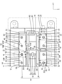
本明細書に開示された技術の実施形態1を、図1から図5を参照しつつ説明する。本実施形態に係る配線モジュール10は、複数(本実施形態では20個)の蓄電素子11を並べてなる蓄電素子群12に取り付けられて蓄電モジュール13を構成する。蓄電モジュール13は、電気自動車又はハイブリッド自動車等の車両(図示せず)に搭載されて、車両を駆動するための動力源として使用される。以下の説明においては、Z方向を上方とし、Y方向を前方とし、X方向を左方として説明する。また、複数の同一部材については、一部の部材に符号を付し、他の部材については符号を省略することがある。
<Embodiment 1>
Embodiment 1 of the technique disclosed herein will be described with reference to FIGS. 1-5. The
蓄電素子11
本実施形態に係る蓄電素子11は二次電池である。蓄電素子11の内部には図示しない蓄電要素が収容されている。蓄電素子11は略直方体形状をなしている。蓄電素子11の上面には前後方向の両端部寄りの位置に、一対の電極端子14が形成されている。電極端子14の一方は正極端子であり、他方は負極端子である。電極端子14の上面には、外周面にねじ山が形成されたスタッドボルトが上方に突出して形成されている。
The
隣り合う電極端子14の極性が同じになるように並べられた2個の蓄電素子11からなる蓄電素子11のペアが、左右方向(並列方向の一例)に複数個並べられることにより、蓄電素子群12が構成されている。蓄電素子11のペアは、隣り合う蓄電素子11のペアの電極端子14の極性が異なるように並べられている。例えば、一の蓄電素子11のペアにおいて、前側に正極が配され、後側に負極が配されていた場合、一の蓄電素子11のペアと隣り合う他の蓄電素子11のペアにおいては、前側に負極が配され、後側に正極が配されるようになっている。
A group of power storage elements by arranging a plurality of pairs of
蓄電素子群12の左右両端部には一対のエンドプレート47,47が配されている。一対のエンドプレート47,47は、蓄電素子群12の前側面及び後側面にボルト49で固定された一対の挟持板48,48によって挟持されている。
A pair of
配線モジュール10
図1に示すように、蓄電素子群12の上面には配線モジュール10が取り付けられている。全体として、配線モジュール10は、左右方向に細長い形状をなしている。
As shown in FIG. 1, a
図1に示すように、配線モジュール10は、前側に配された第1ユニット列30と、後側に配された第2ユニット列31と、第1ユニット列30と第2ユニット列31とを連結する列連結部32と、備える。
As shown in FIG. 1, the
第1ユニット列30
第1ユニット列30は、左右方向に並ぶ複数の第1ユニット33が、第1撓み連結部35(第1連結部の一例)及び第1スライド連結部36(第1連結部の一例)を介して連結されて構成されている。第1ユニット33は絶縁性の合成樹脂からなる。第1ユニット33は、第1バスバー37が収容される第1バスバー収容部38を有する。第1バスバー収容部38は上方から見て略長方形状をなしている。第1バスバー収容部38は上方に開口した箱状に形成されており、この第1バスバー収容部38内に第1バスバー37が収容される。第1バスバー収容部38内には、電圧検知端子22が、第1バスバー37の上に重ねられた状態で、収容されている。第1バスバー37及び電圧検知端子22は、第1バスバー収容部38に設けられた係止爪50によって、上方へ抜け止め状態で保持されている。
In the
図2に示すように、第1ユニット列30の左端部に位置する第1ユニット33と、左から2番目に位置する第1ユニット33とは、第1撓み連結部35によって連結されている。第1撓み連結部35は板状をなしており、左右方向に隣り合う第1ユニット33に一体に形成されている。隣り合う第1ユニット33同士は、複数の第1撓み連結部35(本実施形態では2個)によって連結されている。第1撓み連結部35は、上方から見てU字状をなすと共に、弾性変形可能な撓み部39(第1間隔可変部の一例)を有する。この撓み部39が撓み変形することにより、隣り合う第1ユニット33の間隔が調節可能になっている。
As shown in FIG. 2, the
図4に示すように、第1ユニット列30のうち、左端部に位置する第1ユニット33と、左から2番目に位置する第1ユニット33と異なる第1ユニット33同士は、第1スライド連結部36によって連結されている。第1スライド連結部36は、左右方向に隣り合う第1ユニット33の一方から他方に向けて延出された内壁40A(第1間隔可変部の一例)と、左右方向に隣り合う第1ユニット33の他方から一方に向けて延出されると共に内壁40Aの外方に位置して内壁40Aの外面に摺接する外壁41A(第1間隔可変部の一例)と、を備える。内壁40Aと外壁41Aとは、左右方向にスライド移動可能に形成されている。第1スライド連結部36の内壁40Aと外壁41Aとが左右方向にスライド移動することにより、隣り合う第1ユニット33の間隔が調節可能になっている。
As shown in FIG. 4 , in the
第2ユニット列31
図2から図5に示すように、第2ユニット列31は、左右方向に並ぶ複数の第2ユニット51が、第2連結部52を介して連結されて構成されている。第2ユニット51は、絶縁性の合成樹脂からなり、第2バスバー収容部53を有する。第2バスバー収容部53は上方から見て略長方形状をなしている。第2バスバー収容部53は上方に開口した箱状に形成されており、この第2バスバー収容部53内に第2バスバー54が収容される。第2バスバー収容部53内には、第2バスバー54の上に重ねられた状態で、電圧検知端子22が収容されている。第2バスバー54及び電圧検知端子22は、第2バスバー収容部53に設けられた係止爪50によって、上方へ抜け止め状態で保持されている。
As shown in FIGS. 2 to 5, the
第2連結部52は、左右方向に隣り合う第2ユニット51の一方から他方に向けて延出された内壁40B(第2間隔可変部の一例)と、左右方向に隣り合う第2ユニット51の他方から一方に向けて延出されると共に内壁40Bの外方に位置して内壁40Bの外面に摺接する外壁41B(第2間隔可変部の一例)と、を備える。内壁40Bと外壁41Bとは、左右方向にスライド移動可能に形成されている。第2連結部52の内壁40Bと外壁41Bとが左右方向にスライド移動することにより、隣り合う第2ユニット51の間隔が調節可能になっている。
The second connecting
列連結部32
図2から図5に示すように、列連結部32は、第1ユニット33と、第2ユニット51とに一体に形成されている。列連結部32は、第1ユニット33から第2ユニット51に向けて突出する2枚の第1板状部55と、第2ユニット51から第1ユニット33に向けて突出する2枚の第2板状部56と、第1板状部55と第2板状部56とを連結する、左右方向に細長く延びた長円形状をなす列間隔可変部57と、を有する。列間隔可変部57は、前後方向について弾性変形可能に形成されている。具体的には、第1ユニット列30と第2ユニット列31との間隔が狭くなると列間隔可変部57が前後方向について潰れた形状に撓み変形するようになっている。
As shown in FIGS. 2 to 5, the
第1バスバー37
図1に示すように、第1バスバー37は、金属板材を所定形状にプレス加工してなる。金属板材としては、銅、銅合金、鉄、鉄合金、アルミニウム、アルミニウム合金等、必要に応じて任意の金属を適宜に選択できる。第1バスバー37は上方から見て左右方向に細長く延びた形状をなしている。第1バスバー37には、スタッドボルト42が挿通される複数の貫通孔23Aが第1バスバー37を貫通して形成されている。貫通孔23Aは、左右方向に細長い長円形状をなしている。
As shown in FIG. 1, the
左端部の第1ユニット33に収容された第1バスバー37と、右端部の第1ユニット33に収容された第1バスバー37には、外部回路と蓄電素子群12とを電気的に接続する電力線が接続されるバレル部25が形成されている。バレル部25が電力線24の外周に圧着することにより、電力線と蓄電素子群12とが電気的に接続されるようになっている。左端部の第1ユニット33に収容された第1バスバー37と、右端部の第1ユニット33に収容された第1バスバー37には、2個の貫通孔23Aが形成されている。
A power line for electrically connecting an external circuit and a power
左端部及び右端部に配された第1ユニット33と異なる第1ユニット33に収容された第1バスバー37は、4個の貫通孔23Aが左右方向に並んで形成されている。
The
貫通孔23A内にスタッドボルト42が貫通された状態で、スタッドボルト42に図示しないナットが螺合されることにより、電極端子14と第1バスバー37とが電気的に接続される。
The
第2バスバー54
第2バスバー54には、スタッドボルト42が挿通される複数(本実施形態では4個)の貫通孔23Bが第2バスバー54を貫通して形成されている。貫通孔23Bは、左右方向に細長い長円形状をなしている。
The
貫通孔23B内にスタッドボルト42が貫通された状態で、スタッドボルト42に図示しないナットが螺合されることにより、電極端子14と第2バスバー54とが電気的に接続される。上記以外の構成は第1バスバー37とほぼ同一なので、重複する説明を省略する。
The
電圧検知端子22
図2に示すように、電圧検知端子22は、金属板材を所定形状にプレス加工してなる。金属板材としては銅、銅合金、鉄、鉄合金、アルミニウム、アルミニウム合金等、必要に応じて任意の金属を適宜に選択できる。電圧検知端子22は、板状をなす電極接続部26と、電極接続部26から延出されたバレル部27と、を備える。
As shown in FIG. 2, the
電極接続部26には、スタッドボルト42が挿通される貫通孔23Cが形成されている。電極接続部26が、ナットと、第1バスバー37又は第2バスバー54と、の間に挟まれることにより、電圧検知端子22と電極端子14とが電気的に接続されるようになっている。
A through
バレル部27は、電圧検知線16(電線の一例)の一方の端部に圧着されている。電圧検知線16の他方の端部は、例えばECU(Electronic Contrl Unit)のような外部接続機器(図示せず)に接続されている。
The
なお、ECUは、マイクロコンピュータ、素子等が搭載されたものであって、蓄電素子11の電圧・電流・温度等の検知、各蓄電素子11の充放電コントロール等を行うための機能を備えた周知の構成のものである。
It should be noted that the ECU is equipped with a microcomputer, elements, etc., and is well known to have functions for detecting the voltage, current, temperature, etc. of the
第1配索部28
図2に示すように、配線モジュール10の前端部寄りの位置に配された第1ユニット列30の後部には、左右方向に延びる第1配索部28が形成されている。第1配索部28は上方に開口する溝状に形成されており、内部に電圧検知線16が配索されるようになっている。
As shown in FIG. 2, a
第1延出部61
第1配索部28の後縁部には、第2ユニット列31に向かって後方に延びる複数の第1延出部61が設けられている。第1延出部61は、上方に開口する溝状に形成されており、内部に電圧検知線16が配索されるようになっている。第1延出部61の後端部は、第2ユニット列31と離間している。
A plurality of first extending
第2配索部29
配線モジュール10の後端部寄りの位置に設けられた第2ユニット列31の前部には、左右方向に延びる第2配索部29が形成されている。第2配索部29は上方に開口する溝状に形成されており、内部に電圧検知線16が配索されるようになっている。
A
第2延出部62
第2配索部29の前縁部には、第1ユニット列30に向かって前方に延びる複数の第2延出部62が設けられている。第2延出部62は、上方に開口する溝状に形成されており、内部に電圧検知線16が配索されるようになっている。第2延出部62の前端部は、第1ユニット列30と離間している。
A plurality of second extending
第2延出部62と、第1延出部61とは、上下に重なって配されている。本実施形態では、第2延出部62の上方に第1延出部61が重ねった状態で配されている。第2延出部62の左右方向の幅寸法は、第1延出部61の左右方向の幅寸法よりも大きく設定されている。これにより、第2延出部62の側壁と、第1延出部61の側壁との間には隙間が形成されている。
The
本実施形態の作用、効果
続いて、本実施形態の作用、効果について説明する。本実施形態は、電極端子14を有する複数の蓄電素子11が並列方向に沿って並べられた蓄電素子群12に配設される配線モジュール10であって、電極端子14に接続される少なくとも1個の第1バスバー37を収容する複数の第1ユニット33が、複数の第1ユニット33同士の間隔を調節可能な撓み部39を有する第1撓み連結部35、及び内壁40A、外壁41Aを有する第1スライド連結部36を介して連結されている第1ユニット列30と、電極端子14に接続される少なくとも1個の第2バスバー54を収容する複数の第2ユニット51が、複数の第2ユニット51同士の間隔を調節可能な内壁40B、外壁41Bを有する第2連結部52を介して連結されると共に、第1ユニット列30に並んで配置される第2ユニット列31と、第1ユニット列30と第2ユニット列31の双方に接続されて第1ユニット列30と第2ユニット列31とを連結すると共に、第1ユニット列30と第2ユニット列31との間隔を調節可能な列間隔可変部57を有する列連結部32と、を備える。
Actions and effects of the present embodiment Next, the actions and effects of the present embodiment will be described. This embodiment is a
上記の構成によれば、撓み部39、内壁40A、外壁41A、及び内壁40B、外壁41Bによって、並列方向に沿って並べられた複数の蓄電素子11の電極端子14同士の公差に対応することができる。また、列間隔可変部57によって、第1ユニット列30と第2ユニット列31の間隔についての公差に対応することができる。
According to the above configuration, the bending
左右方向最大
図2には、左右方向について、複数の蓄電素子11の公差が最大となった状態における配線モジュール10を示す。長孔形状をなす第1バスバー37の貫通孔23A内において、電極端子14に設けられたスタッドボルト42は、貫通孔23Aの中心からずれて位置している。また、隣り合う第1ユニット33の間に位置する第1撓み連結部35は、左右方向について延びた状態になっている。また、隣り合う第1ユニット33の間に位置する第1スライド連結部36においては、内壁40Aと外壁41Aとが前後方向に重なる領域が最小となっている。また、隣り合う第2ユニット51の間に位置する第2連結部52においては、内壁40Bと外壁41Bとが前後方向に重なる領域が最小となっている。このようにして、左右方向について、複数の蓄電素子11の公差が最大となった状態において、各公差が足し合わされた状態に対応することができる。
Maximum in the left-right direction FIG. 2 shows a
一方、図3には、左右方向について、複数の蓄電素子11の公差が最小となった状態における配線モジュール10を示す。長孔形状をなす第1バスバー37の貫通孔23A内において、電極端子14に設けられたスタッドボルト42は、貫通孔23Aの中心からずれて位置している。隣り合う第1ユニット33の間に位置する第1撓み連結部35は、左右方向について縮んだ状態になっている。また、隣り合う第1ユニット33の間に位置する第1スライド連結部36においては、内壁40Aと外壁41Aとが前後方向に重なる領域が最大となっている。また、隣り合う第2ユニット51の間に位置する第2連結部52においては、内壁40Bと外壁41Bとが前後方向に重なる領域が最大となっている。このようにして、左右方向について、複数の蓄電素子11の公差が最小となった状態において、各公差が足し合わされた状態に対応することができる。
On the other hand, FIG. 3 shows a
図4には、前後方向について、蓄電素子11の電極端子14間の公差が最大となった状態における配線モジュール10を示す。列間隔可変部57は長円形状をなしており、図2に表された列間隔可変部57よりも、前後方向についてやや膨らんだ状態になっている。このようにして、前後方向について、蓄電素子11の電極端子14間の公差が最大となった状態に対応することができる。
FIG. 4 shows a
図5には、前後方向について、蓄電素子11の電極端子14間の公差が最小となった状態における配線モジュール10を示す。列間隔可変部57は、図2に表された列間隔可変部57よりも、前後方向について潰れた形状をなしている。このようにして、前後方向について、蓄電素子11の電極端子14間の公差が最小となった状態に対応することができる。
FIG. 5 shows a
また、本実施形態によれば、第1ユニット列30に設けられた第1配索部28は第2ユニット列31に向かって延びる第1延出部61を有し、第2ユニット列31に設けられた第2配索部29は第1ユニット列30に向かって延びると共に、第1延出部61と少なくとも一部が重なって配される第2延出部62を有し、第1配索部28、第1延出部61、第2配索部29、及び第2延出部62には電圧検知線16が配されている。
Further, according to the present embodiment, the
上記の構成によれば、第1延出部61及び第2延出部62を介することにより、第1配索部28と、第2配索部29との間に電圧検知線16を架け渡して配索することができる。これにより、電圧検知線16の配索についての自由度が向上するので、配線モジュール10内で電圧検知線16を容易に取り回すことができる。
According to the above configuration, the
図4には、前後方向について、蓄電素子11の電極端子14間の公差が最大となった状態における配線モジュール10を示す。この状態において、第1配索部28と第2配索部29とが前後方向について重なる領域は、最小となっている。このようにして、前後方向について、蓄電素子11の電極端子14間の公差が最大となった状態においても、公差に対応することにより、電圧検知線16を第1配索部28と第2配索部29との間に架け渡して配索することができる。
FIG. 4 shows a
図5には、前後方向について、蓄電素子11の電極端子14間の公差が最小となった状態における配線モジュール10を示す。この状態において、第1配索部28と第2配索部29とが前後方向について重なる領域は、最大となっている。このようにして、前後方向について、蓄電素子11の電極端子14間の公差が最小となった状態においても、公差に対応することにより、電圧検知線16を第1配索部28と第2配索部29との間に架け渡して配索することができる。
FIG. 5 shows a
<他の実施形態>
本明細書に開示された技術は上記記述及び図面によって説明した実施形態に限定されるものではなく、例えば次のような実施形態も本明細書に開示された技術の技術的範囲に含まれる。
<Other embodiments>
The techniques disclosed herein are not limited to the embodiments described above and in the drawings, and for example, the following embodiments are also included in the technical scope of the techniques disclosed herein.
(1)本実施形態においては、電線は電圧検知線16としたが、これに限られず、蓄電素子11の温度を検知するための電線でもよく、他の機器の電線であってもよい。
(1) In the present embodiment, the electric wire is the
(2)本実施形態においては、第1延出部が上側に位置し、第2延出部が下側に位置する状態で互いに重なった位置に配されていたが、これに限られず、第1延出部61が下側で、第2延出部62が上側に位置して重なる構成としてもよい。
(2) In the present embodiment, the first extending portion is located on the upper side and the second extending portion is located on the lower side, and the second extending portion is arranged at a position where they overlap each other, but the present invention is not limited to this. 1 The
(3)蓄電素子11はキャパシタであってもよい。
(3) The
(4)第1連結部は、第1ユニット33と一体になった形状に限らず、別体であってもよい。また、第2連結部も、第2ユニット51と一体になった形状に限らず、別体であってもよい。
(4) The first connecting portion is not limited to the shape integrated with the
(5)上記実施形態では、第1バスバー37及び第2バスバー54は、異極の電極端子14を接続(蓄電素子11を直列接続)するものとしたが、これに限られず、同極の電極端子14を接続(蓄電素子11を並列接続)するものでもよい。例えば、上記実施形態の配線モジュールに更に別の蓄電素子11を並列接続し、この並列接続における同極の電極端子14を電気的に接続するようにしたものでもよい。
(5) In the above embodiment, the
(6)蓄電素子11の個数は任意に選択することができる。
(6) The number of
10:配線モジュール
11:蓄電素子
12:蓄電素子群
14:電極端子
16:電圧検知線
28:第1配索部
29:第2配索部
30:第1ユニット列
31:第2ユニット列
32:列連結部
33:第1ユニット
35:第1撓み連結部
36:第1スライド連結部
37:第1バスバー
39:撓み部
40A,40B:内壁
41A,41B:外壁
51:第2ユニット
52:第2連結部
54:第2バスバー
57:列間隔可変部
61:第1延出部
62:第2延出部
10: Wiring module 11: Power storage element 12: Power storage element group 14: Electrode terminal 16: Voltage detection line 28: 1st wiring unit 29: 2nd wiring unit 30: 1st unit row 31: 2nd unit row 32: Row connecting part 33: 1st unit 35: 1st bending connecting part 36: 1st slide connecting part 37: 1st bus bar 39: Flexing
Claims (1)
前記電極端子に接続される少なくとも1個の第1バスバーを収容する複数の第1ユニットが、前記複数の第1ユニット同士の間隔を調節可能な第1間隔可変部を有する第1連結部を介して連結されている第1ユニット列と、
前記電極端子に接続される少なくとも1個の第2バスバーを収容する複数の第2ユニットが、前記複数の第2ユニット同士の間隔を調節可能な第2間隔可変部を有する第2連結部を介して連結されると共に、前記第1ユニット列に並んで配置される第2ユニット列と、
前記第1ユニット列と前記第2ユニット列の双方に接続されて前記第1ユニット列と前記第2ユニット列とを連結すると共に、前記第1ユニット列と前記第2ユニット列との間隔を調節可能な列間隔可変部を有する列連結部と、
を備え、
前記第1ユニット列に設けられた第1配索部は前記第2ユニット列に向かって延びる第1延出部を有し、
前記第2ユニット列に設けられた第2配索部は前記第1ユニット列に向かって延びると共に、前記第1延出部と少なくとも一部が重なって配される第2延出部を有し、
前記第1配索部、前記第1延出部、前記第2配索部、及び前記第2延出部には電線が配されている、配線モジュール。 A wiring module in which a plurality of energy storage elements having electrode terminals are arranged in a group of energy storage elements arranged in a parallel direction.
A plurality of first units accommodating at least one first bus bar connected to the electrode terminals are via a first connecting portion having a first spacing variable portion capable of adjusting the spacing between the plurality of first units. 1st unit row connected by
A plurality of second units accommodating at least one second bus bar connected to the electrode terminal are via a second connecting portion having a second spacing variable portion capable of adjusting the spacing between the plurality of second units. The second unit row, which is connected and arranged side by side in the first unit row,
It is connected to both the first unit row and the second unit row to connect the first unit row and the second unit row, and adjusts the distance between the first unit row and the second unit row. A column connection with a variable column spacing and a column connection
Equipped with
The first wiring portion provided in the first unit row has a first extending portion extending toward the second unit row.
The second wiring portion provided in the second unit row extends toward the first unit row and has a second extending portion which is arranged so as to at least partially overlap with the first extending portion. ,
A wiring module in which electric wires are arranged in the first wiring section, the first extension section, the second wiring section, and the second extension section.
Priority Applications (3)
| Application Number | Priority Date | Filing Date | Title |
|---|---|---|---|
| JP2018097204A JP6988687B2 (en) | 2018-05-21 | 2018-05-21 | Wiring module |
| US16/400,560 US11322802B2 (en) | 2018-05-21 | 2019-05-01 | Wiring module |
| CN201910380105.7A CN110518180B (en) | 2018-05-21 | 2019-05-08 | Wiring module |
Applications Claiming Priority (1)
| Application Number | Priority Date | Filing Date | Title |
|---|---|---|---|
| JP2018097204A JP6988687B2 (en) | 2018-05-21 | 2018-05-21 | Wiring module |
Publications (2)
| Publication Number | Publication Date |
|---|---|
| JP2019204597A JP2019204597A (en) | 2019-11-28 |
| JP6988687B2 true JP6988687B2 (en) | 2022-01-05 |
Family
ID=68533148
Family Applications (1)
| Application Number | Title | Priority Date | Filing Date |
|---|---|---|---|
| JP2018097204A Active JP6988687B2 (en) | 2018-05-21 | 2018-05-21 | Wiring module |
Country Status (3)
| Country | Link |
|---|---|
| US (1) | US11322802B2 (en) |
| JP (1) | JP6988687B2 (en) |
| CN (1) | CN110518180B (en) |
Families Citing this family (2)
| Publication number | Priority date | Publication date | Assignee | Title |
|---|---|---|---|---|
| JP6981924B2 (en) * | 2018-06-01 | 2021-12-17 | 株式会社オートネットワーク技術研究所 | Wiring module |
| JP7157039B2 (en) * | 2019-11-29 | 2022-10-19 | 矢崎総業株式会社 | busbar module |
Family Cites Families (29)
| Publication number | Priority date | Publication date | Assignee | Title |
|---|---|---|---|---|
| US3960602A (en) * | 1974-01-21 | 1976-06-01 | Gould Inc. | Intercell connector assembly for positive displacement casting system |
| US7635537B2 (en) * | 2005-07-05 | 2009-12-22 | Concorde Battery Corporation | Lead-acid storage batteries with lightweight connectors |
| JP5139745B2 (en) * | 2007-08-10 | 2013-02-06 | 矢崎総業株式会社 | Power supply |
| JP4856041B2 (en) * | 2007-10-10 | 2012-01-18 | パナソニック株式会社 | Video / audio recording and playback device |
| EP2418688A4 (en) * | 2009-04-08 | 2013-08-21 | Sharp Kk | Interconnect sheet, solar cell with interconnect sheet, solar module, and method of producing solar cell with interconnect sheet |
| KR20110018261A (en) * | 2009-08-17 | 2011-02-23 | 삼성전자주식회사 | Method and apparatus for processing text subtitle data |
| JP5550290B2 (en) * | 2009-09-17 | 2014-07-16 | 矢崎総業株式会社 | Electric wire arrangement, bus bar module, and power supply device |
| JP5506307B2 (en) * | 2009-09-24 | 2014-05-28 | 矢崎総業株式会社 | Electric wire routing device |
| KR101146677B1 (en) * | 2009-10-30 | 2012-05-22 | 에스비리모티브 주식회사 | Busbar holder |
| JP5510707B2 (en) * | 2009-12-14 | 2014-06-04 | 株式会社オートネットワーク技術研究所 | Battery connection assembly |
| JP5490522B2 (en) * | 2009-12-25 | 2014-05-14 | 株式会社翔栄 | Touch panel and manufacturing method thereof |
| JP5504977B2 (en) * | 2010-03-02 | 2014-05-28 | 株式会社オートネットワーク技術研究所 | Battery connection assembly |
| CN101917557B (en) * | 2010-08-10 | 2012-06-27 | 浙江大学 | Method for dynamically adding subtitles based on video content |
| JP5585846B2 (en) * | 2011-07-05 | 2014-09-10 | 株式会社オートネットワーク技術研究所 | Battery wiring module |
| JP6163361B2 (en) * | 2013-06-07 | 2017-07-12 | 矢崎総業株式会社 | Bus bar module and power supply |
| JP6182992B2 (en) * | 2013-06-14 | 2017-08-23 | 株式会社Gsユアサ | Power storage module |
| JP6230460B2 (en) * | 2013-06-17 | 2017-11-15 | 昭和電工パッケージング株式会社 | Molding packaging material |
| JP5447724B1 (en) * | 2013-07-30 | 2014-03-19 | 株式会社オートネットワーク技術研究所 | Wiring module |
| JP6016737B2 (en) * | 2013-08-29 | 2016-10-26 | 古河電気工業株式会社 | In-battery wiring module of battery pack |
| JP6198061B2 (en) * | 2013-10-28 | 2017-09-20 | 株式会社オートネットワーク技術研究所 | Wiring module |
| JP6451650B2 (en) * | 2014-01-17 | 2019-01-16 | 三洋電機株式会社 | Power supply |
| US20150214534A1 (en) * | 2014-01-27 | 2015-07-30 | Ford Global Technologies, Llc | Devices and methods for connecting battery cells |
| DE112015000809T5 (en) * | 2014-02-14 | 2016-11-24 | Yazaki Corporation | Busbar module |
| JP2015159024A (en) * | 2014-02-24 | 2015-09-03 | 愛三工業株式会社 | bus bar module |
| KR102341402B1 (en) * | 2015-05-15 | 2021-12-20 | 삼성에스디아이 주식회사 | Battery module |
| US9837774B2 (en) * | 2015-11-04 | 2017-12-05 | Yazaki Corporation | Fixing structure between busbar and terminal |
| JP6620565B2 (en) * | 2016-01-20 | 2019-12-18 | セイコーエプソン株式会社 | Printed wiring board, information communication device, and display system |
| JP6469062B2 (en) * | 2016-09-30 | 2019-02-13 | 株式会社オートネットワーク技術研究所 | Connection module |
| JP7119762B2 (en) * | 2018-08-22 | 2022-08-17 | トヨタ自動車株式会社 | connection module |
-
2018
- 2018-05-21 JP JP2018097204A patent/JP6988687B2/en active Active
-
2019
- 2019-05-01 US US16/400,560 patent/US11322802B2/en active Active
- 2019-05-08 CN CN201910380105.7A patent/CN110518180B/en active Active
Also Published As
| Publication number | Publication date |
|---|---|
| JP2019204597A (en) | 2019-11-28 |
| US11322802B2 (en) | 2022-05-03 |
| US20190355955A1 (en) | 2019-11-21 |
| CN110518180B (en) | 2022-06-03 |
| CN110518180A (en) | 2019-11-29 |
Similar Documents
| Publication | Publication Date | Title |
|---|---|---|
| JP5838721B2 (en) | Battery module and wiring module | |
| US10553917B2 (en) | Conductor module | |
| WO2013069756A1 (en) | Wiring module | |
| JP7099054B2 (en) | Wiring module and power storage module | |
| CN112272896B (en) | Wiring module | |
| JP6717788B2 (en) | Conductor module | |
| WO2015163126A1 (en) | Wiring module, wiring-module intermediary body, and method for manufacturing wiring module | |
| US20170294640A1 (en) | Wiring module and method for producing wiring module | |
| WO2017010295A1 (en) | Wiring module | |
| US10062891B2 (en) | Wiring module | |
| US20190386282A1 (en) | Connection module | |
| JP6988687B2 (en) | Wiring module | |
| JP2015028858A (en) | Wiring module | |
| US11075430B2 (en) | Wiring module | |
| JP2012227002A (en) | Wiring module | |
| US10923292B2 (en) | Wiring module | |
| US20230231259A1 (en) | Battery wiring module | |
| US11349179B2 (en) | Wiring module and power storage module | |
| JP7336065B2 (en) | Wiring module and power storage module | |
| WO2024075687A1 (en) | Wiring module | |
| JP2024055096A (en) | Wiring Module |
Legal Events
| Date | Code | Title | Description |
|---|---|---|---|
| A521 | Request for written amendment filed |
Free format text: JAPANESE INTERMEDIATE CODE: A523 Effective date: 20190117 |
|
| A621 | Written request for application examination |
Free format text: JAPANESE INTERMEDIATE CODE: A621 Effective date: 20200827 |
|
| A977 | Report on retrieval |
Free format text: JAPANESE INTERMEDIATE CODE: A971007 Effective date: 20210623 |
|
| A131 | Notification of reasons for refusal |
Free format text: JAPANESE INTERMEDIATE CODE: A131 Effective date: 20210629 |
|
| A521 | Request for written amendment filed |
Free format text: JAPANESE INTERMEDIATE CODE: A523 Effective date: 20210806 |
|
| TRDD | Decision of grant or rejection written | ||
| A01 | Written decision to grant a patent or to grant a registration (utility model) |
Free format text: JAPANESE INTERMEDIATE CODE: A01 Effective date: 20211102 |
|
| A61 | First payment of annual fees (during grant procedure) |
Free format text: JAPANESE INTERMEDIATE CODE: A61 Effective date: 20211115 |
|
| R150 | Certificate of patent or registration of utility model |
Ref document number: 6988687 Country of ref document: JP Free format text: JAPANESE INTERMEDIATE CODE: R150 |