JP6987879B2 - Dynamic transient period configuration for shortened transmission time intervals - Google Patents
Dynamic transient period configuration for shortened transmission time intervals Download PDFInfo
- Publication number
- JP6987879B2 JP6987879B2 JP2019551594A JP2019551594A JP6987879B2 JP 6987879 B2 JP6987879 B2 JP 6987879B2 JP 2019551594 A JP2019551594 A JP 2019551594A JP 2019551594 A JP2019551594 A JP 2019551594A JP 6987879 B2 JP6987879 B2 JP 6987879B2
- Authority
- JP
- Japan
- Prior art keywords
- data
- type
- transient period
- uplink transmission
- tti
- Prior art date
- Legal status (The legal status is an assumption and is not a legal conclusion. Google has not performed a legal analysis and makes no representation as to the accuracy of the status listed.)
- Active
Links
Images


Classifications
-
- H—ELECTRICITY
- H04—ELECTRIC COMMUNICATION TECHNIQUE
- H04L—TRANSMISSION OF DIGITAL INFORMATION, e.g. TELEGRAPHIC COMMUNICATION
- H04L5/00—Arrangements affording multiple use of the transmission path
- H04L5/003—Arrangements for allocating sub-channels of the transmission path
- H04L5/0048—Allocation of pilot signals, i.e. of signals known to the receiver
- H04L5/0051—Allocation of pilot signals, i.e. of signals known to the receiver of dedicated pilots, i.e. pilots destined for a single user or terminal
-
- H—ELECTRICITY
- H04—ELECTRIC COMMUNICATION TECHNIQUE
- H04L—TRANSMISSION OF DIGITAL INFORMATION, e.g. TELEGRAPHIC COMMUNICATION
- H04L5/00—Arrangements affording multiple use of the transmission path
- H04L5/003—Arrangements for allocating sub-channels of the transmission path
- H04L5/0058—Allocation criteria
- H04L5/0064—Rate requirement of the data, e.g. scalable bandwidth, data priority
-
- H—ELECTRICITY
- H04—ELECTRIC COMMUNICATION TECHNIQUE
- H04L—TRANSMISSION OF DIGITAL INFORMATION, e.g. TELEGRAPHIC COMMUNICATION
- H04L5/00—Arrangements affording multiple use of the transmission path
- H04L5/003—Arrangements for allocating sub-channels of the transmission path
- H04L5/0078—Timing of allocation
- H04L5/0087—Timing of allocation when data requirements change
-
- H—ELECTRICITY
- H04—ELECTRIC COMMUNICATION TECHNIQUE
- H04W—WIRELESS COMMUNICATION NETWORKS
- H04W72/00—Local resource management
- H04W72/04—Wireless resource allocation
- H04W72/044—Wireless resource allocation based on the type of the allocated resource
- H04W72/0446—Resources in time domain, e.g. slots or frames
-
- H—ELECTRICITY
- H04—ELECTRIC COMMUNICATION TECHNIQUE
- H04W—WIRELESS COMMUNICATION NETWORKS
- H04W72/00—Local resource management
- H04W72/20—Control channels or signalling for resource management
- H04W72/21—Control channels or signalling for resource management in the uplink direction of a wireless link, i.e. towards the network
-
- H—ELECTRICITY
- H04—ELECTRIC COMMUNICATION TECHNIQUE
- H04W—WIRELESS COMMUNICATION NETWORKS
- H04W72/00—Local resource management
- H04W72/50—Allocation or scheduling criteria for wireless resources
- H04W72/56—Allocation or scheduling criteria for wireless resources based on priority criteria
- H04W72/566—Allocation or scheduling criteria for wireless resources based on priority criteria of the information or information source or recipient
- H04W72/569—Allocation or scheduling criteria for wireless resources based on priority criteria of the information or information source or recipient of the traffic information
-
- H—ELECTRICITY
- H04—ELECTRIC COMMUNICATION TECHNIQUE
- H04L—TRANSMISSION OF DIGITAL INFORMATION, e.g. TELEGRAPHIC COMMUNICATION
- H04L1/00—Arrangements for detecting or preventing errors in the information received
- H04L1/0001—Systems modifying transmission characteristics according to link quality, e.g. power backoff
- H04L1/0002—Systems modifying transmission characteristics according to link quality, e.g. power backoff by adapting the transmission rate
- H04L1/0003—Systems modifying transmission characteristics according to link quality, e.g. power backoff by adapting the transmission rate by switching between different modulation schemes
-
- H—ELECTRICITY
- H04—ELECTRIC COMMUNICATION TECHNIQUE
- H04W—WIRELESS COMMUNICATION NETWORKS
- H04W72/00—Local resource management
- H04W72/20—Control channels or signalling for resource management
- H04W72/23—Control channels or signalling for resource management in the downlink direction of a wireless link, i.e. towards a terminal
Landscapes
- Engineering & Computer Science (AREA)
- Signal Processing (AREA)
- Computer Networks & Wireless Communication (AREA)
- Quality & Reliability (AREA)
- Mobile Radio Communication Systems (AREA)
- Transmitters (AREA)
- Stabilization Of Oscillater, Synchronisation, Frequency Synthesizers (AREA)
- Reduction Or Emphasis Of Bandwidth Of Signals (AREA)
Description
相互参照
本特許出願は、2018年3月15日付で出願された「Dynamic Transient Period Configurations For Shortened Transmission Time Intervals」と題されたAkula et alによる米国特許出願第15/922,616号、および2017年3月24日付で出願された「Dynamic Transient Period Configurations for Shortened Transmission Time Intervals」と題されたAkula et alによる米国仮特許出願第62/476,485号に対する優先権を主張し、その各々が本願の譲り受け人に譲渡されている。
Cross-reference This patent application is a US patent application No. 15 / 922,616 by Akula et al entitled "Dynamic Transient Period Configurations For Shortened Transmission Time Intervals" filed March 15, 2018, and 2017. Claiming priority over US Provisional Patent Application No. 62 / 476,485 by Akula et al entitled "Dynamic Transient Period Configurations for Shortened Transmission Time Intervals" filed on March 24, each of which is in the present application. It has been transferred to the transferee.
[0002] 以下は、概して、ワイヤレス通信に関し、より具体的には、短縮された送信時間間隔(sTTI)のための動的な過渡期間構成に関する。 [0002] The following generally relates to wireless communication and, more specifically, to dynamic transient time configurations for shortened transmission time intervals (sTTI).
[0003] ワイヤレス通信システムは、音声、映像、パケットデータ、メッセージング、ブロードキャストなどのような様々なタイプの通信コンテンツを提供するために広く展開されている。これらのシステムは、利用可能なシステムリソース(例えば、時間、周波数、および電力)を共有することによって複数のユーザとの通信をサポートすることが可能であり得る。このような多元接続システムの例は、符号分割多元接続(CDMA)システム、時分割多元接続(TDMA)システム、周波数分割多元接続(FDMA)システム、および直交周波数分割多元接続(OFDMA)システム(例えば、ロングタームエボリューション(LTE(登録商標))システム、または新規の無線(NR:New Radio)システム)を含む。ワイヤレス多元接続通信システムは、いくつかの基地局またはアクセスネットワークノードを含み得、各々が、別名ユーザ機器(UE)として知られ得る複数の通信デバイスのための通信を同時にサポートする。 [0003] Wireless communication systems are widely deployed to provide various types of communication content such as voice, video, packet data, messaging, broadcast and the like. These systems may be able to support communication with multiple users by sharing available system resources (eg, time, frequency, and power). Examples of such multiple access systems include code division multiple access (CDMA) systems, time division multiple access (TDMA) systems, frequency division multiple access (FDMA) systems, and orthogonal frequency division multiple access (OFDM) systems (eg, eg). Includes Long Term Evolution (LTE® system, or New Radio (NR) system). A wireless multiple access communication system may include several base stations or access network nodes, each of which simultaneously supports communication for multiple communication devices, also known as user equipment (UEs).
[0004] いくつかのLTEまたはNR展開での基地局は、異なる長さの送信時間間隔(TTI)を使用して、1つまたは複数のUEへ送信し得る。いくつかのケースでは、これらのTTIは、レガシLTE TTIに関連する(relative to)長さに低減され得る。このような低減された長さの送信時間間隔(TTI)は、短縮されたTTI(sTTI)と呼ばれ得、sTTIを使用して通信するユーザは、低レイテンシユーザと呼ばれ得る。sTTIは、レガシサブフレームに対応する1つまたは複数のより長い持続期間TTIのサブセットであり得る―例えば、より長い持続期間TTIは、LTEなどの規格化された無線アクセス技術(RAT)に基づくニューメロロジ(numerology)を有し得る。基地局は、sTTI送信のために使用されるべき時間リソース、周波数リソース、および1つまたは複数のコンポーネントキャリア(CC)を含み得る、sTTIのための送信リソースをUEに割り振り得る。データ、制御情報、および基準信号送信のためのこのようなリソースの効率的な使用は、ワイヤレス通信システムの効率を上げるための手助けとなり得る。 [0004] Base stations in some LTE or NR deployments may transmit to one or more UEs using transmission time intervals (TTIs) of different lengths. In some cases, these TTIs can be reduced to relative to lengths associated with legacy LTE TTIs. Such a reduced length transmission time interval (TTI) may be referred to as a shortened TTI (sTTI), and a user communicating using sTTI may be referred to as a low latency user. The sTTI can be a subset of one or more longer duration TTIs corresponding to the legacy subframe-for example, the longer duration TTI is a numerology based on a standardized radio access technology (RAT) such as LTE. Can have (numerology). The base station may allocate to the UE transmission resources for sTTI, which may include time resources, frequency resources, and one or more component carriers (CCs) to be used for sTTI transmission. Efficient use of such resources for data, control information, and reference signal transmission can help increase the efficiency of wireless communication systems.
[0005] 説明された技法は、sTTIのための動的な過渡期間構成をサポートする、改善された方法、システム、デバイス、または装置に関する。 [0005] The techniques described relate to improved methods, systems, devices, or devices that support dynamic transient period configurations for sTTI.
[0006] ワイヤレス通信の方法が説明される。方法は、アップリンク送信のためのリソース許可(resource grant)を識別することと、ここで、アップリンク送信は、第1の基準信号(RS)と、少なくとも第2のRSおよびデータを含む送信時間間隔(TTI)とを備え、第1のRSのタイプ、第2のRSのタイプ、およびデータのタイプを識別することと、第1のRSのタイプ、第2のRSのタイプ、およびデータのタイプに少なくとも部分的に基づいて、第1のRS、第2のRS、およびデータに関連付けられた優先順位を決定することと、決定された優先順位に少なくとも部分的に基づいて、第1のRS、またはTTI、または両方とオーバーラップする過渡期間を動的に構成することと、構成された過渡期間を備えるアップリンク送信を送信することと、を含み得る。 [0006] A method of wireless communication is described. The method identifies a resource grant for the uplink transmission, where the uplink transmission includes a first reference signal (RS) and at least a second RS and data transmission time. It has an interval (TTI) to identify the type of first RS, the type of second RS, and the type of data, and the type of first RS, the type of second RS, and the type of data. To determine the priority associated with the first RS, the second RS, and the data, at least in part, and in the first RS, at least in part, based on the determined priority. Alternatively, it may include dynamically configuring a transient period that overlaps with TTI, or both, and transmitting an uplink transmission with the configured transient period.
[0007] ワイヤレス通信のための装置が説明される。装置は、アップリンク送信のためのリソース許可を識別するための手段と、ここで、アップリンク送信は、第1のRSと、少なくとも第2のRSおよびデータを含むTTIとを備え、第1のRSのタイプ、第2のRSのタイプ、およびデータのタイプを識別するための手段と、第1のRSのタイプ、第2のRSのタイプ、およびデータのタイプに少なくとも部分的に基づいて、第1のRS、第2のRS、およびデータに関連付けられた優先順位を決定するための手段と、決定された優先順位に少なくとも部分的に基づいて、第1のRS、またはTTI、または両方とオーバーラップする過渡期間を動的に構成するための手段と、構成された過渡期間を備えるアップリンク送信を送信するための手段と、を含み得る。 [0007] A device for wireless communication is described. The apparatus comprises a means for identifying resource permissions for the uplink transmission, wherein the uplink transmission comprises a first RS and at least a second RS and a TTI containing data, the first. A means for identifying the type of RS, the type of the second RS, and the type of data, and at least in part based on the type of the first RS, the type of the second RS, and the type of data. Over the first RS, or TTI, or both, based on the means for determining the priorities associated with the first RS, the second RS, and the data, and at least in part based on the determined priorities. It may include means for dynamically configuring the transitional period to wrap and means for transmitting an uplink transmission with the configured transient period.
[0008] ワイヤレス通信のための別の装置が説明される。装置は、プロセッサと、プロセッサと電子通信するメモリと、メモリに記憶された命令とを含み得る。命令は、アップリンク送信のためのリソース許可を識別することと、ここで、アップリンク送信は、第1のRSと、少なくとも第2のRSおよびデータを含むTTIとを備え、第1のRSのタイプ、第2のRSのタイプ、およびデータのタイプを識別することと、第1のRSのタイプ、第2のRSのタイプ、およびデータのタイプに少なくとも部分的に基づいて、第1のRS、第2のRS、およびデータに関連付けられた優先順位を決定することと、決定された優先順位に少なくとも部分的に基づいて、第1のRS、またはTTI、または両方とオーバーラップする過渡期間を動的に構成することと、構成された過渡期間を備えるアップリンク送信を送信することと、をプロセッサに行わせるように実行可能であり得る。 [0008] Another device for wireless communication is described. The device may include a processor, a memory that electronically communicates with the processor, and instructions stored in the memory. The instruction identifies a resource permission for the uplink transmission, wherein the uplink transmission comprises a first RS and at least a second RS and a TTI containing data of the first RS. Identifying the type, the type of the second RS, and the type of data, and the first RS, based at least in part on the type of the first RS, the type of the second RS, and the type of data. Determine the priority associated with the second RS, and the data, and move the transition period that overlaps with the first RS, or TTI, or both, at least in part based on the determined priority. It may be possible to force the processor to configure and send an uplink transmission with a configured transient period.
[0009] ワイヤレス通信のための非一時的コンピュータ可読媒体が説明される。非一時的コンピュータ可読媒体は、アップリンク送信のためのリソース許可を識別することと、ここで、アップリンク送信は、第1のRSと、少なくとも第2のRSおよびデータを含むTTIとを備え、第1のRSのタイプ、第2のRSのタイプ、およびデータのタイプを識別することと、第1のRSのタイプ、第2のRSのタイプ、およびデータのタイプに少なくとも部分的に基づいて、第1のRS、第2のRS、およびデータに関連付けられた優先順位を決定することと、決定された優先順位に少なくとも部分的に基づいて、第1のRS、またはTTI、または両方とオーバーラップする過渡期間を動的に構成することと、構成された過渡期間を備えるアップリンク送信を送信することと、をプロセッサに行わせるように動作可能な命令を含み得る。 [0009] A non-transient computer-readable medium for wireless communication is described. A non-transient computer-readable medium identifies a resource permit for an uplink transmission, wherein the uplink transmission comprises a first RS and a TTI containing at least a second RS and data. Identifying the type of first RS, the type of second RS, and the type of data, and at least partially based on the type of first RS, the type of second RS, and the type of data. Determining the priorities associated with the first RS, second RS, and data, and overlapping with the first RS, or TTI, or both, at least in part based on the determined priorities. It may include instructions that can be operated to cause the processor to dynamically configure the transition period to be performed and to send an uplink transmission with the configured transition period.
[0010] 上述された方法、装置、および非一時的コンピュータ可読媒体のいくつかの例は、第1のRSがアップリンク送信内で第2のRSと隣接し得ると決定するための処理、特徴、手段、または命令をさらに含み得る。上述された方法、装置、および非一時的コンピュータ可読媒体のいくつかの例では、過渡期間は、第1のRSが第2のRSに隣接するとの決定に少なくとも部分的に基づいて、第1のRSおよび第2のRSとオーバーラップするように構成され得る。上述された方法、装置、および非一時的コンピュータ可読媒体のいくつかの例では、過渡期間は、第1のRSが第2のRSに隣接するとの決定に少なくとも部分的に基づいて、第2のRSとオーバーラップするように構成され得る。 [0010] Some examples of the methods, devices, and non-transient computer-readable media described above are processes, features for determining that a first RS may be adjacent to a second RS in an uplink transmission. , Means, or instructions may be further included. In some examples of the methods, devices, and non-transient computer-readable media described above, the transient period is the first, at least partially based on the determination that the first RS is adjacent to the second RS. It can be configured to overlap the RS and the second RS. In some examples of the methods, devices, and non-transient computer-readable media described above, the transient period is at least partially based on the determination that the first RS is adjacent to the second RS. It can be configured to overlap the RS.
[0011] 上述された方法、装置、および非一時的コンピュータ可読媒体のいくつかの例は、第1のRSがアップリンク送信内でTTIのデータと隣接し得ると決定するための処理、特徴、手段、または命令をさらに含み得る。上述された方法、装置、および非一時的コンピュータ可読媒体のいくつかの例では、過渡期間は、第1のRSがデータに隣接するとの決定に少なくとも部分的に基づいて、データとオーバーラップするように構成され得る。上述された方法、装置、および非一時的コンピュータ可読媒体のいくつかの例では、過渡期間は、第1のRSがデータに隣接するとの決定に少なくとも部分的に基づいて、第1のRSとオーバーラップするように構成され得る。上述された方法、装置、および非一時的コンピュータ可読媒体のいくつかの例では、過渡期間は、第1のRSがデータに隣接するとの決定に少なくとも部分的に基づいて、第1のRSおよびデータとオーバーラップするように構成され得る。 [0011] Some examples of the methods, devices, and non-transient computer-readable media described above are processes, features, for determining that a first RS may be adjacent to TTI data within an uplink transmission. It may further include means or instructions. In some examples of the methods, devices, and non-transient computer-readable media described above, the transient period overlaps the data, at least in part, based on the determination that the first RS is adjacent to the data. Can be configured in. In some examples of the methods, devices, and non-transient computer-readable media described above, the transient period exceeds the first RS, at least in part, based on the determination that the first RS is adjacent to the data. Can be configured to wrap. In some examples of the methods, devices, and non-transient computer-readable media described above, the transient period is at least partially based on the determination that the first RS is adjacent to the data, the first RS and the data. Can be configured to overlap with.
[0012] 上述された方法、装置、および非一時的コンピュータ可読媒体のいくつかの例では、第1のRSのタイプを識別することは、アップリンク送信のアップリンク構成に少なくとも部分的に基づいて、RSの周期性を識別することを備える。上述された方法、装置、および非一時的コンピュータ可読媒体のいくつかの例では、データのタイプを識別することは、データ、またはデータのコンテンツ、または両方に関連付けられた変調および符号化方式(MCS)を識別することを備える。上述された方法、装置、および非一時的コンピュータ可読媒体のいくつかの例では、データのコンテンツは、確認応答(acknowledgement)または否定確認応答(negative acknowledgement)を備える。 [0012] In some examples of the methods, devices, and non-transient computer-readable media described above, identifying the type of first RS is at least partially based on the uplink configuration of the uplink transmission. , Provided to identify the periodicity of RS. In some examples of the methods, devices, and non-transient computer-readable media described above, identifying the type of data is a modulation and coding scheme (MCS) associated with the data, or the content of the data, or both. ) Is provided. In some examples of the methods, devices, and non-transient computer-readable media described above, the content of the data comprises an acknowledgment or a negative acknowledgement.
[0013] 上述された方法、装置、および非一時的コンピュータ可読媒体のいくつかの例では、TTIまたは第1のRSは、別のワイヤレスデバイスに関連付けられ得る。上述された方法、装置、および非一時的コンピュータ可読媒体のいくつかの例では、第1のRSは、サウンディング基準信号(SRS)を備える。上述された方法、装置、および非一時的コンピュータ可読媒体のいくつかの例では、第2のRSは、復調基準信号(DMRS:demodulation reference signal)を備える。 [0013] In some examples of the methods, devices, and non-transient computer-readable media described above, the TTI or first RS may be associated with another wireless device. In some examples of the methods, devices, and non-transient computer-readable media described above, the first RS comprises a sounding reference signal (SRS). In some examples of the methods, devices, and non-transient computer-readable media described above, the second RS comprises a demodulation reference signal (DMRS).
[0021] 低レイテンシ通信を拡張し得るsTTIのためのタイムマスク技法をサポートするための、改善された方法、システム、デバイス、または装置の様々な例が使用され得る。低レイテンシ通信のために割り振られたリソースは、1ミリ秒(ms)TTI持続期間を使用し得る拡張されたモバイルブロードバンド(eMBB:enhanced mobile broadband)送信などの、比較的レイテンシに敏感でない(relatively latency insensitive)通信のTTIに関する低減された長さを有するsTTIを使用して、アップリンクおよびダウンリンク通信のために使用され得る。sTTIを使用する通信は、いくつかのケースでは、ワイヤレスサブフレームの1スロットに対応するsTTI持続期間、あるいは、2つまたは3つの直交周波数分割多重化(OFDM)シンボルに対応するsTTI持続期間を使用し得る。いくつかのケースでは、sTTIは、1ミリ秒TTIのスロットの境界とアラインされるか(aligned)、または該スロット内に複数の境界を有するように構成され得る。いくつかの例では、sTTIは2つまたは3つのOFDMシンボルにわたり得、各スロットは3つのsTTIを有し得る。このような方法では、通常のサイクリックプレフィックスを使用するスロットの全ての7つのシンボルが利用され得、システムリソースは、3つの2シンボルsTTIが7シンボルスロットに含まれ得るケースに関して、より効率的に利用され得る。 [0021] Various examples of improved methods, systems, devices, or devices may be used to support time mask techniques for sTTI that may extend low latency communication. Resources allocated for low latency communications are relatively relatively latency, such as enhanced mobile broadband (eMBB) transmissions that can use a 1 millisecond (ms) TTI duration. Insensitive) sTTI with reduced length for communication TTI can be used for uplink and downlink communication. Communication using sTTI, in some cases, uses the sTTI duration corresponding to one slot of the wireless subframe, or the sTTI duration corresponding to two or three orthogonal frequency division multiplexing (OFDM) symbols. Can be. In some cases, the sTTI may be aligned with or configured to have multiple boundaries within the slot of a 1 millisecond TTI. In some examples, the sTTI may span two or three OFDM symbols, and each slot may have three sTTIs. In such a method, all seven symbols of a slot using a normal cyclic prefix can be utilized and system resources are more efficient in cases where three two-symbols sTTI can be contained in a seven-symbol slot. Can be used.
[0022] 本明細書で説明される様々な技法は、送信の特性(例えば、電力の変化、リソースブロック(RB)割り振り変更など)を識別し、その送信のエラーセンシティブな(error-sensitive)部分の保護の強化(increased protection)を提供する方法で、sTTIを使用する送信のための過渡(transient)領域(例えば、タイムマスク)のロケーションを動的に決定することを提供し得る。本開示は、高帯域幅動作、より動的なサブフレーム/スロットタイプ、および自給式(self-contained)サブフレーム/スロットタイプ(サブフレーム/スロットのためのハイブリッド自動再送要求(HARQ)フィードバックが、サブフレーム/スロットの終わりの前に送信され得る)などの特徴をサポートするために設計される次世代ネットワーク(例えば、5GまたはNRネットワーク)を参照する様々な技法を説明する。しかしながら、このような技法は、異なる長さのTTIがワイヤレス通信システム中で送信され得る任意のシステムのために使用され得る。 [0022] Various techniques described herein identify transmission characteristics (eg, power changes, resource block (RB) allocation changes, etc.) and the error-sensitive portion of the transmission. In a way that provides increased protection, it may be possible to dynamically determine the location of a transient region (eg, a time mask) for transmission using sTTI. The present disclosure provides high bandwidth operation, more dynamic subframe / slot types, and self-contained subframe / slot types (hybrid automatic repeat request (HARQ) feedback for subframes / slots. Describes various techniques that refer to next generation networks (eg, 5G or NR networks) designed to support features such as (which can be transmitted before the end of a subframe / slot). However, such techniques can be used for any system in which TTIs of different lengths can be transmitted in a wireless communication system.
[0023] 本開示の態様は初めに、ワイヤレス通信システムのコンテキストで説明される。異なるTTIのための過渡期間およびタイムマスクの様々な例が次に説明される。本開示の態様はさらに、sTTIのためのタイムマスク技法に関する、装置図、システム図、およびフローチャートによって図示され、それらを参照して説明される。 [0023] Aspects of the present disclosure are first described in the context of wireless communication systems. Various examples of transient periods and time masks for different TTIs are described below. Aspects of the present disclosure are further illustrated and described with reference to device diagrams, system diagrams, and flowcharts relating to time mask techniques for sTTI.
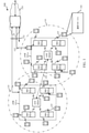
[0024] 図1は、本開示の様々な態様に従った、ワイヤレス通信システム100の例を図示する。ワイヤレス通信システム100は、基地局105(例えば、ネットワークアクセスデバイス、gNodeB(gNB)、および/または無線ヘッド(RH))、UE115、およびコアネットワーク130を含み得る。いくつかの例では、ワイヤレス通信システム100は、LTE(またはLTEアドバンスト)ネットワーク、またはNRネットワークであり得る。いくつかのケースでは、ワイヤレス通信システム100は、拡張されたブロードバンド通信、高信頼性(すなわち、ミッションクリティカルな)通信、低レイテンシ通信、および低コストかつ低複雑度のデバイスを用いた通信をサポートし得る。
[0024] FIG. 1 illustrates an example of a
[0025] コアネットワーク130は、ユーザ認証、アクセス承認、追跡、インターネットプロトコル(IP)接続性、および他のアクセス、ルーティング、またはモビリティ機能を提供し得る。基地局105(例えば、eNodeB(eNBs)105−aまたはアクセスノードコントローラ(ANC)105−b、gNB)のうちの少なくともいくつかは、バックホールリンク132(例えば、S1、S2など)を通じてコアネットワーク130とインターフェースし得、UE115との通信のために無線構成およびスケジューリングを行い得る。様々な例では、ANC105−bは、直接的にまたは間接的に(例えば、コアネットワーク130を通じて)、ワイヤードまたはワイヤレス通信リンクであり得るバックホールリンク134(例えば、X1、X2など)上で互いと通信し得る。各アクセスノードコントローラ(ANC)105−bはまた、いくつかのスマート無線ヘッド(無線ヘッド)105−cを通じていくつかのUE115と通信し得る。ワイヤレス通信システム100の代替的な構成では、ANC105−bの機能は、無線ヘッド105−cによって提供されるか、またはeNB105−aの無線ヘッド105−cにわたって分散され得る。ワイヤレス通信システム100の別の代替的な構成では、無線ヘッド105−cは、基地局と置き換えられ得、ANC105−bは、基地局制御装置によって置き換えられ得る(またはコアネットワーク130にリンクする)。
[0025] The
[0026] ANC105−bは、各無線ヘッド105−cが1つまたは複数のアンテナを有している1つまたは複数の無線ヘッド105−cを介してUE115とワイヤレスに通信し得る。無線ヘッド105−cの各々は、それぞれの地理的カバレッジエリア110に対して通信カバレッジを提供し得る。無線ヘッド105−cのための地理的カバレッジエリア110は、カバレッジエリアの一部のみを構成するセクタ(図示せず)に分割され得る。いくつかの例では、ネットワークアクセスデバイス105は、基地トランシーバ局、無線基地局、アクセスポイント、無線トランシーバ、ノードB、eノードB(eNB)、ホームノードB、ホームeノードBなどのような代替的なネットワークアクセスデバイスと置き換えられ得る。ワイヤレス通信システム100は、異なるタイプ(例えば、マクロセルおよび/またはスモールセルネットワークアクセスデバイス)の無線ヘッド105−c(または基地局105または他のネットワークアクセスデバイス)を含み得る。無線ヘッド105−cまたは他のネットワークアクセスデバイスの地理的カバレッジエリア110は、オーバーラップし得る。いくつかの例では、異なるeNB105−aは、異なる無線アクセス技術に関連付けられ得る。
The ANC 105-b may communicate wirelessly with the
[0027] UE115は、ワイヤレス通信システム100全体にわたって分散され、各UE115は、固定式または移動式であり得る。UE115はまた、当業者によって、移動局、加入者局、モバイルユニット、加入者ユニット、ワイヤレスユニット、リモートユニット、モバイルデバイス、ワイヤレスデバイス、ワイヤレス通信デバイス、リモートデバイス、モバイル加入者局、アクセス端末、モバイル端末、ワイヤレス端末、リモート端末、ハンドセット、ユーザエージェント、モバイルクライアント、クライアント、または何らかの他の適切な用語で呼ばれ得るか、またはそれらを含み得る。UE115は、セルラフォン、携帯情報端末(PDA)、ワイヤレスモデム、ワイヤレス通信デバイス、ハンドヘルドデバイス、タブレットコンピュータ、ラップトップコンピュータ、コードレスフォン、ワイヤレスローカルループ(WLL)局、IoEデバイスなどであり得る。UE115は、マクロeNB、スモールセルeNB、リレー基地局などを含む、eNB105−a、無線ヘッド105−c、基地局105、アクセスポイント、または他のネットワークデバイスの様々なタイプと通信することが可能でき得る。UEはまた、(例えば、ピア・ツー・ピア(P2P)プロトコルを使用して)他のUE115と直接通信することができ得る。いくつかのケースでは、UE115は、通信リンク135を通じてコアネットワーク130と通信し得る。
[0027]
[0028] いくつかの例では、ワイヤレス通信システム100は、5Gネットワークを含み得る。他の例では、ワイヤレス通信システム100は、LTE/LTE−Aネットワークを含み得る。ワイヤレス通信システム100は、いくつかのケースでは、異種ネットワークであり得、異なるタイプのeNBは、様々な地理的領域のためのカバレッジを提供する。例えば、各eNB105−aまたは無線ヘッド105−cは、マクロセル、スモールセル、および/または他のタイプのセルに対する通信カバレッジを提供し得る。「セル」という用語は、コンテキストに依存して、基地局、無線ヘッド、基地局または無線ヘッドに関連付けられたキャリアまたはコンポーネントキャリア、あるいは、キャリアまたは基地局のカバレッジエリア(例えば、セクタなど)を説明するために使用されることができる、3GPP(登録商標)の用語である。
[0028] In some examples, the
[0029] 基地局105は、1つまたは複数の基地局アンテナを介してUE115とワイヤレスに通信し得る。各基地局105は、それぞれの地理的なカバレッジエリア110に対して通信カバレッジを提供し得る。ワイヤレス通信システム100中に示された通信リンク125は、UE115から基地局105へのアップリンク送信、または基地局105からUE115へのダウンリンク送信を含み得る。制御情報およびデータは、様々な技法に従ったアップリンクチャネルまたはダウンリンク上で多重化され得る。制御情報およびデータは、例えば、時分割多重化(TDM)技法、周波数分割多重化(FDM)技法、またはハイブリッドTDM−FDM技法を使用して、ダウンリンクチャネル上で多重化され得る。通信リンク125上の送信は、変調および符号化方式(MCS)によって符号化され得、それは、所与の送信のためのデータレートに寄与し得る。例えば、チャネル条件が良好である(例えば、干渉が小さい)ときには、増加した量の情報が、低いMCSに関する所与の時間期間内に搬送されることができるように、高いMCSが用いられ得る。
[0029]
[0030] いくつかのケースでは、UE115はまた、(例えば、ピア・ツー・ピア(P2P)またはデバイス・ツー・デバイス(D2D)プロトコルを使用して)他のUEと直接通信することも可能であり得る。マシンタイプ通信(MTC)またはIoTデバイスなどの、いくつかのUE115は、低コストまたは低複雑度のデバイスであり得、マシン間の自動化された通信、すなわち、マシン・ツー・マシン(M2M)通信を提供し得る。M2MまたはMTCは、デバイスが人間の介在なしに互いにまたは基地局と通信することを可能にするデータ通信技術を指し得る。MTCデバイスのためのアプリケーションの例は、スマートメータリング、在庫モニタリング、水位モニタリング、機器モニタリング、ヘルスケアモニタリング、野生生物モニタリング、天候および地質学的イベントモニタリング、フリート(fleet)管理および追跡、リモートセキュリティ感知、物理アクセス制御、および取引ベースのビジネス課金(transaction-based business charging)を含む。
[0030] In some cases, the
[0031] 基地局105は、コアネットワーク130と通信し、かつ互いと通信し得る。例えば、基地局105は、バックホールリンク132(例えば、S1、S2など)を通じてコアネットワーク130とインターフェースし得る。基地局105は、直接的にまたは間接的に(例えば、コアネットワーク130を通じて)、バックホールリンク134(例えば、X1、X2など)上で互いと通信し得る。基地局105は、UE115との通信のために無線構成およびスケジューリングを行い得るか、または基地局コントローラ(図示せず)の制御下で動作し得る。いくつかの例では、基地局105は、マクロセル、スモールセル、ホットスポット、または同様のものであり得る。基地局105は、LTE eNB、eLTE eNB、NR gNB、NRノードB、NRアクセスノードの例であり得、ANCを含み得る。
The
[0032] UE115は、通信マネージャ102を含み得、それは、アップリンク送信のためのリソース許可を識別することと、ここで、アップリンク送信は、第1のRSと、少なくとも第2のRSおよびデータを含むTTIとを含み、第1のRSのタイプ、第2のRSのタイプ、およびデータのタイプを識別することと、第1のRSのタイプ、第2のRSのタイプ、データのタイプに少なくとも部分的に基づいて、第1のRS、第2のRS、およびデータに関連付けられた優先順位を決定することと、決定された優先順位に基づいて、第1のRS、またはTTI、または両方とオーバーラップする過渡期間を動的に構成することと、構成された過渡期間を含むアップリンク送信を送信することと、を行い得る。
[0032] The
[0033] 基地局105は、バックホールリンク132(例えば、S1、S2、NG−1、NG−2、NG−3、NG−C、NG−Uなど)を通してコアネットワーク130とインターフェースし得、関連付けられたカバレッジエリア110内のUE115との通信のための無線構成およびスケジューリングを行い得る。様々な例では、ネットワークデバイス(例えば、gNB、eNB105−a、ANC105−b、RH105−c)は、ワイヤードまたはワイヤレス通信リンクであり得るバックホールリンク134(例えば、X1、X2、Xnなど)上で互いと直接的にまたは間接的に(例えば、コアネットワーク130を通じて)通信し得る。各基地局105はまた、いくつかの他のネットワークデバイスを通じて、いくつかのUE115と通信し得、ここで、ネットワークデバイスは、送受信ポイント(TRP:transmission reception point)、分散型ユニット(DU:distributed unit)、無線ヘッド(RH)、リモート無線ヘッド(RRH:remote radio head)、またはスマート無線ヘッドの一例であり得る。
[0033]
[0034] ワイヤレス通信システム100は、複数のセルまたはキャリア上での動作をサポートし得、その特徴は、キャリアアグリゲーション(CA)またはマルチキャリア動作と呼ばれ得る。キャリアはまた、コンポーネントキャリア(CC)、レイヤ、チャネルなどと呼ばれ得る。「キャリア」、「コンポーネントキャリア」、「セル」、および「チャネル」という用語は、本明細書で交換して使用され得る。UE115は、キャリアアグリゲーションのために、複数のダウンリンクCCと、1つまたは複数のアップリンクCCとで構成され得る。キャリアアグリゲーションは、周波数分割複信(FDD)と時分割複信(TDD)コンポーネントキャリアとの両方を用いて使用され得る。
[0034] The
[0035] いくつかのケースでは、ワイヤレス通信システム100は、拡張コンポーネントキャリア(eCC)を利用し得る。eCCは、より広い帯域幅、より短いシンボル持続期間、および短いTTIを含む、1つまたは複数の機能によって特徴付けられ得る。いくつかのケースでは、eCCは、(例えば、複数のサービングセルが準最適または非理想的バックホールリンクを有するとき)キャリアアグリゲーション構成またはデュアルコネクティビティ構成に関連付けられ得る。eCCはまた、(1より多いオペレータがスペクトルを使用することを可能にする)共有スペクトルまたはアンライセンススペクトルで使用するために構成され得る。いくつかのケースでは、eCCは、他のCCとは異なるシンボル持続期間を利用し得、それは、他のCCのシンボル持続期間と比較して、低減されたシンボル持続期間の使用を含み得る。より短いシンボル持続期間は、増加したサブキャリア間隔に関連付けられる。eCCを利用するUE115または基地局105などのデバイスは、低減されたシンボル持続期間(例えば、16.67マイクロ秒)でワイドバンド信号(例えば、20、40、60、80MHzなど)を送信し得る。eCCにおけるTTIは、1つまたは複数のシンボルから構成され得る。いくつかのケースでは、TTI持続期間(すなわち、TTI中のシンボルの数)は、可変であり得る。5GまたはNRキャリアは、eCCと見なされ得る。
[0035] In some cases, the
[0036] いくつかのケースでは、ワイヤレス通信システム100は、ライセンスおよびアンライセンス無線周波数スペクトルバンドの両方を利用し得る。例えば、ワイヤレス通信システム100は、LTEライセンス補助アクセス(LTE−LAA:LTE(登録商標) License Assisted Access)、またはLTEアンライセンス(LTE U:LTE Unlicensed)無線アクセス技術、または5GHzの産業用、化学用、および医療用(ISM:Industrial, Scientific, and Medical)バンドなどのアンライセンスバンドにおけるNR技術を用い得る。アンライセンス無線周波数スペクトルバンドで動作しているとき、基地局105およびUE115などのワイヤレスデバイスは、データを送信する前にチャネルがクリアであることを保証するためのリッスンビフォアトーク(LBT:listen-before-talk)プロシージャを利用し得る。いくつかのケースでは、アンライセンスバンドでの動作は、ライセンスバンド中で動作するコンポーネントキャリア(CC)と連携するキャリアアグリゲーション(CA)構成に基づき得る。アンライセンススペクトルでの動作は、ダウンリンク送信、アップリンク送信、または両方を含み得る。アンライセンススペクトルでの複信(duplexing)は、周波数分割複信(FDD)、時分割複信(TDD)、または両方の組み合わせに基づき得る。
[0036] In some cases, the
[0037] LTEまたはNRにおける時間間隔は、(TS=1/30,720,000秒のサンプリング期間であり得る)基本時間単位の倍数で(in multiples of)表現され得る。LTE/LTE−Aにおける時間リソースは、10ミリ秒の長さの無線フレーム(Tf=307200TS)に従って組織化され得、それは、0から1023に及ぶシステムフレーム番号(SFN:system frame number)で識別され得る。各フレームは、0から9まで番号付けされた10個の1ミリ秒サブフレームを含み得る。サブフレームは、2つの0.5msスロットにさらに分割され得、その各々が(各シンボルに付加されたサイクリックプレフィックスの長さに依存して)6または7変調シンボル期間を含んでいる。サイクリックプレフィックスを除くと、各シンボルは、2048個のサンプル期間を含んでいる。いくつかのケースでは、サブフレームは、TTIとしても知られる最小スケジューリング単位であり得る。他のケースでは、TTIは、(例えば、sTTIバースト中で、またはsTTIを使用する選択されたコンポーネントキャリア中で)サブフレームよりも短いか、または動的に選択され得る。本明細書で説明される様々な例は、短縮されたTTIのための送信技法を提供し、それは、送信機をパワーオンまたはパワーオフすることに関連付けられた過渡信号(transients)、または他の送信に関連付けられた過渡信号からの比較的小さい影響でsTTI送信を提供するために、sTTI持続期間外に過渡期間タイムマスク(transient period time masks)を提供し得る。 [0037] time interval in LTE or NR can be (possible with T S = 1 / 30,720,000 second sampling period) in multiples of the basic time unit (in multiples of) expression. Time resources in LTE / LTE-A may be organized according to the length of 10 ms radio frame (T f = 307200T S), it is the system frame number ranging from 0 to 1023: in (SFN system frame number) Can be identified. Each frame may contain 10 1 millisecond subframes numbered from 0 to 9. The subframe can be further divided into two 0.5 ms slots, each containing a 6 or 7 modulation symbol period (depending on the length of the cyclic prefix attached to each symbol). Excluding the cyclic prefix, each symbol contains 2048 sample periods. In some cases, subframes can be the smallest scheduling unit, also known as TTI. In other cases, the TTI may be shorter or dynamically selected than the subframe (eg, in an sTTI burst or in a selected component carrier using sTTI). The various examples described herein provide transmission techniques for shortened TTI, which are transients associated with powering on or off the transmitter, or other. Transient period time masks may be provided outside the sTTI duration to provide sTTI transmission with a relatively small effect from the transient signal associated with the transmission.
[0038] 例えば、UE115は、広い送信帯域幅にわたる受信信号電力を基地局105が測定するのを手助けする、サウンディング基準信号(SRS)を送信し得る。基地局105は、周波数依存型スケジューリング(frequency-dependent scheduling)のためにSRSから収集した情報を使用し得る。いくつかのケースでは、UE115は、sTTIを用いて連続的にSRSを送信し得る。本明細書で説明される様々な技法は、SRSとUE115の他の送信との間の衝突を防ぐために用いられ得る。いくつかのケースでは、説明された技法は、(例えば、MCS、SRS送信の周期性に基づいて)送信スキームの動的な選択を可能にし得る。
[0038] For example, the
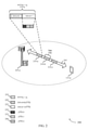
[0039] 図2は、本開示の1つまたは複数の態様をサポートするワイヤレス通信システム200の例を図示する。ワイヤレス通信システム200は、図1に関連して上述されるような、対応するデバイスの態様の例であり得る、基地局105−aおよびUE115−aを含む。図2の例では、ワイヤレス通信システム200は、5GまたはNRなどのRATに従って動作し得るが、本明細書で説明される技法は、いずれのRATにも適用されることができ、かつ2つ以上の異なるRATを同時に使用し得るシステムに適用されることができる。
[0039] FIG. 2 illustrates an example of a
[0040] 基地局105−aは、キャリア205上でUE115−aと通信し得る。いくつかの例では、基地局105−aは、キャリア205上でUE115と通信するためにリソースを割り振り得る。例えば、基地局105−aは、UE115−aと通信するためにサブフレーム210を割り振り、1つまたは複数のサブフレーム210は、1ミリ秒のTTI長を有するレガシLTE TTIに対応し得る。この例では、サブフレーム210は、第1のサブフレーム210−a、第2のサブフレーム210−b、および第3のサブフレーム210−cを含み得る。サブフレーム210の各々は、2つのスロットを含み得、各スロットは、通常のサイクリックプレフィックスのための7つのシンボルを有し得る。この例では、第1のサブフレーム210−aは、sTTI送信のための(例えば、sTTIを使用する低レイテンシサービスの送信のための)リソースを含み得、第2のサブフレーム210−bは、1ミリ秒TTIのための(例えば、レガシLTE送信または1ミリ秒TTIを使用する別の送信のための)リソースを含み得る。
[0040] Base station 105-a may communicate with UE 115-a on
[0041] この例の第1のサブフレーム210−aは、第1のスロット(スロット0)220および第2のスロット(スロット1)225を含む。上述されるように、低レイテンシシステムのアップリンクでは、異なるsTTI長は、キャリア205上の送信のために使用され得る。例えば、2シンボルsTTI、3シンボルsTTI、および1スロットsTTIの持続期間は、物理アップリンク制御チャネル(PUCCH)および物理アップリンク共有チャネル(PUSCH)送信(または短縮されたPUCCH(sPUCCH)および短縮されたPUSCH(sPUSCH)送信)に関してサポートされ得る。よって、第1のスロット220または第2のスロット225内に、各々が2つまたは3つのOFDMシンボル持続期間を有し得る第1のsTTI(TTI−0)230、第2のsTTI(TTI−1)235、および第3のsTTI(TTI−2)240などの複数のsTTIが存在し得る。
[0041] The first subframe 210-a of this example includes a first slot (slot 0) 220 and a second slot (slot 1) 225. As mentioned above, in the uplinks of low latency systems, different sTTI lengths can be used for transmission on
[0042] 2シンボルまたは3シンボルsTTIが使用されるとき、いくつかのケースでは、sTTI境界は、スロット境界内に位置するか、またはスロットアライン型sTTI(slot-aligned sTTIs)とも呼ばれ得る、第1のスロット220または第2のスロット225の境界のようなスロット境界にアラインされた、固定されたsTTI構造を有することが望ましい。上述されるように、通常のCPを使用しているとき、各スロット220、225に7つのシンボルが含まれ、各スロットは、スロットアライン型sTTIの場合3つのsTTIを含み得る。
[0042] When a two-symbol or three-symbol sTTI is used, in some cases the sTTI boundaries may be located within the slot boundaries or may also be referred to as slot-aligned sTTIs (slot-aligned sTTIs). It is desirable to have a fixed sTTI structure aligned to a slot boundary, such as the boundary of
[0043] 本明細書で説明されるように、タイムマスクは、SRSを用いて連続的に送信されるsTTIに対して、異なって適用され得る。いくつかのワイヤレス通信システム(例えば、LTE)では、SRSおよびPUSCHが(例えば、同じTTI内で)連続的に送信されたときの過渡領域は、完全に、TTI(例えば、サブフレーム210−bまたは1ミリ秒TTI)のPUSCH部分内で発生し得る。従って、SRSは完全に保護されるものとみなされ得る。すなわち、SRSは、過渡期間とオーバーラップするTTIのPUSCH部分よりも受信機(例えば、基地局105)で成功裏に受信される可能性がより高くなり得る。しかしながら、sTTIのより短い持続期間のために、このような実装は問題があり得る。例えば、1ミリ秒TTIが使用されるいくつかの実装では、オン−オフまたはオフ−オンの遷移の間、20マイクロ秒(μs)の過渡時間(transient time)が存在し得る。1ミリ秒TTI内にこのような過渡期間を有すると、1ミリ秒TTI持続期間のうちの最大で2%がこれらの過渡期間によって影響を受け得る。しかしながら、送信機がsTTIを送信しているとき、このような過渡期間の影響は、より大きくなり得る。例えば、2シンボルsTTIが使用されている場合に、20μsの過渡期間が存在すると、sTTI持続期間のうちの10%超がこのような過渡期間によって影響を受け得る。これらの持続期間は、例示のためだけに使用されるものであり、他の過渡期間の持続期間もまた考慮される。 [0043] As described herein, time masks may be applied differently to sTTI transmitted continuously using SRS. In some wireless communication systems (eg LTE), the transient region when SRS and PUSCH are transmitted continuously (eg, within the same TTI) is completely TTI (eg, subframe 210-b or). It can occur within the PUSCH portion of 1 millisecond TTI). Therefore, SRS can be considered to be fully protected. That is, the SRS may be more likely to be successfully received by the receiver (eg, base station 105) than the PUSCH portion of the TTI that overlaps the transient period. However, due to the shorter duration of sTTI, such implementations can be problematic. For example, in some implementations where 1 millisecond TTI is used, there may be 20 microseconds (μs) of transient time between on-off or off-on transitions. Having such transients within a 1 ms TTI, up to 2% of the 1 ms TTI duration can be affected by these transients. However, when the transmitter is transmitting sTTI, the effect of such transients can be greater. For example, if a two-symbol sTTI is used and a transient period of 20 μs is present, more than 10% of the sTTI duration can be affected by such a transient period. These durations are used for illustration purposes only and the durations of other transitional periods are also considered.
[0044] 本開示の態様では、過渡期間のためのタイムマスクは、(例えば、各領域または何らかのそのようなファクタにおける情報のセンシティビティに応じて)このような過渡期間がsTTIまたはSRSの持続期間外に発生することを保証するために、(例えば、動的に)適用され得る。すなわち、sTTIのコンテンツは、過渡期間が送信の特定の部分のみに影響を与えるように考慮され得、それは、送信デバイスによってコヒーレントに決定され得る。このようなケースでは、sTTIおよび/またはSRS送信上の過渡期間の影響が低減され得、それは、受信機におけるsTTIおよび/またはSRSの成功裏の受信の可能性を高め得る。 [0044] In aspects of the present disclosure, the timemask for a transient period (eg, depending on the sensitivity of the information in each region or some such factor) is that such a transient period is the duration of the sTTI or SRS. It can be applied (eg, dynamically) to ensure that it occurs outside. That is, the content of the sTTI can be considered such that the transient period affects only certain parts of the transmission, which can be coherently determined by the transmitting device. In such cases, the effect of transient periods on the sTTI and / or SRS transmission may be reduced, which may increase the chances of successful reception of the sTTI and / or SRS at the receiver.
[0045] 下記で説明されるように、タイムマスク(例えば、本明細書では代替的にパワーマスク(power mask)と呼ばれ得る)を決定するときに、様々なファクタが考慮され得る。例えば、sTTI内のPUSCH送信の復調基準信号(DMRS)部分がSRSの隣にある(例えば、時間的に隣接する)場合、タイムマスクを決定するために複数のオプションが存在し得、UE115は、以下に説明されるファクタのうちの1つまたは複数に基づいて、これらのオプション間で動的に選択することが可能であり得る。例えば、いくつかのケースでは、UE115は、DMRSを常に保護するように構成され得る(すなわち、それにより、SRS送信内に過渡期間が発生し得、それは、単一のOFDMシンボルを表し得る)。いくつかのケースでは、追加的にまたは代替的に、UE115は、非周期的なSRS送信を保護するように(すなわち、過渡期間がDMRSおよび/またはPUSCH sTTIのデータ部分内で発生し得るように)構成され得る。別の例では、周期的なSRS送信に関して、過渡期間(transient times)は、(例えば、このようなSRS送信の周期性が、過渡領域に関連付けられたエラーを送信するために、それらをよりロバストにし得るため)SRSシンボル内に収容され得る。一般に、パワーマスクは、SRSタイプ(例えば、周期的または非周期的な)、データ領域のMCS、またはいくつかの他の同様のファクタに従って、特定のケースごとに調整され(tailored)得る。さらに、いくつかのケースでは、隣接するシンボルは、過渡期間の負の効果(negative effect)のバランスをとるために、全体の過渡時間(transient time)を共有し得る。
[0045] As described below, various factors may be considered when determining the time mask (eg, which may be referred to herein as an alternative power mask). For example, if the demodulation reference signal (DMRS) portion of the PUSCH transmission in the sTTI is next to the SRS (eg, temporally adjacent), there may be multiple options for determining the time mask, the
[0046] いくつかの例では、タイムマスクは、アプリケーションに依存し得る。例えば、DMRSおよびデータは、高信頼性低レイテンシ通信(URLLC:ultra-reliable, low latency communications)のために十分に保護され得る。追加的にまたは代替的に、マスクは、LTE超低レイテンシ(ULL:ultra-low latency)通信のために、DMRSとSRSとの間で分割され得る。様々な例では、UE115が過渡期間(すなわち、タイムマスク)を適宜適応させることができるように、UE115は、URLLCトラフィックのためにスケジュールされるか、またはULLのためにスケジュールされるかを、(例えば、アップリンク許可から)決定し得る。
[0046] In some examples, the time mask may be application dependent. For example, DMRS and data may be well protected for high reliability and low latency communications (URLLC). Additional or alternative, the mask may be split between DMRS and SRS for LTE ultra-low latency (ULL) communication. In various examples, the
[0047] これらケースはまた、1つのUE115のためのSRSが第2のUE115のsTTIに連続すると見なされる。すなわち、本明細書で説明される動的なタイムマスキング技法は、連続的なSRSおよびPUSCH sTTIが、同じUE115に関連付けられる、または異なるUE115に関連付けられるシナリオに適用可能であり得る。例えば、サブフレームの最後のsTTI(例えば、サブフレーム210−aのsTTI240などの時間的に最後のsTTI)では、第1のUE115は、sTTI240の最後のシンボル中でSRSを送り得るが、一方、第2のUE115は、データ/DMRS送信のための後続のサブフレーム(例えば、サブフレーム210−b)の最初の2つのシンボルを使用し得る。
[0047] In these cases, the SRS for one
[0048] 代替的に、サブフレームの時間的に最後のsTTI(例えば、sTTI240)が3シンボルsTTIである場合には、過渡時間は、(例えば、DMRSが既に保護されているため)第1のUE115のSRSと第2のUE115のデータシンボルとの間で分割され得る。このようなケースでは、sTTIが、(例えば、異なるサブバンド中で、または異なるユーザによって送られるSRSを含む)DMRS、データ、および別の信号、またはヌル(例えば、対応するOFDMシンボル上で送られる信号が存在しない)のために使用されるシンボルを含み得る。追加的にまたは代替的に、タイムマスクは、データシンボルのコンテンツに基づき得る。例えば、確認応答/否定確認応答(ACK/NACK)ビットを搬送するデータシンボルは、DMRSおよび/またはSRSよりも優先され(例えば、保護され)得る。これらの例はまた、UE115のためのsTTIがセル固有のSRS送信機会に隣接しているときのケースにも適用され得る(すなわち、UE115によるSRS送信は存在しないが、他のUE115は、セル固有のSRSシンボル中に送信し得る)。
[0048] Alternatively, if the temporally last sTTI (eg, sTTI240) of the subframe is the three-symbol sTTI, then the transient time is the first (eg, because the DMRS is already protected). It may be split between the SRS of the
[0049] 図3は、ワイヤレスリソース300、オフ−オン過渡タイムマスクおよびオン−オフ過渡タイムマスクの例を図示する。ワイヤレスリソース300は、例えば、図1および図2に関して上述されたような、UE115と基地局105との間の低レイテンシ通信のためのsTTI送信で使用され得る。図3の例では、送信機の電力は、公称(nominal)オフ電力レベル305を有するオフ状態から、公称オン電力レベル310を有するオン状態へと変化し得る。第1の過渡期間315は、オフ電力レベル305からオン電力レベル310に送信機が切り替わるための期間に対応し得る。第2の過渡期間320は、オン電力レベル310からオフ電力レベル305に送信機が切り替わるための期間に対応し得る。
[0049] FIG. 3 illustrates examples of
[0050] 上述されるように、これらの過渡期間は、送信電力および/またはRB割り振りが変化する領域(すなわち、周波数ホッピング)を指し得る。SRS送信が比較的広い帯域幅上で発生するため、SRSおよびPUSCH送信の並列(juxtaposition)がこのような過渡領域をもたらし得る。さらに上述されるように、このような過渡領域中に発生する送信は、成功裏の受信のより低い可能性(lower likelihood of successful reception)に関連付けられ得る。従って、デバイスは、過渡領域の負の効果が軽減され得るように送信をフォーマットするために、本明細書で説明される技法を使用するように構成され得る。 [0050] As mentioned above, these transients can refer to regions where transmit power and / or RB allocation varies (ie, frequency hopping). Since SRS transmissions occur over a relatively wide bandwidth, juxtaposition of SRS and PUSCH transmissions can result in such transient regions. Further, as described above, transmissions that occur during such transient regions can be associated with a lower likelihood of successful reception. Thus, the device may be configured to use the techniques described herein to format the transmission so that the negative effects of the transient region can be mitigated.
[0051] 例えば、また上で示されるように、いくつかのケースでは、過渡期間は、送信のエラーセンシティブな部分の持続期間外の過渡期間を提供するためにマスキングされ得る。図3の例では、保護された期間の開始325は、第1の過渡期間315の終わりに対応し得る。これに対応して、保護された期間の終わり330は、第2の過渡期間320の開始に対応し得る。以下で説明される様々な例では、UE115は、保護された期間内の信号(または時間/周波数リソースの領域)が第1の過渡期間315および第2の過渡期間320に関して比較的影響されないように、保護された期間中、(例えば、異なるコンテンツを有する)信号の異なるタイプを送信するように構成され得る。
[0051] For example, as also shown above, in some cases the transient period may be masked to provide a transient period outside the duration of the error-sensitive portion of the transmission. In the example of FIG. 3, the
[0052] 図4Aおよび図4Bは、本開示の1つまたは複数の態様をサポートするそれぞれのタイムマスク構成400および450の例を図示する。UE115は、これらのタイムマスク構成と、本開示の様々な態様において説明される多様なファクタ(例えば、データのMCS、SRSの周期性など)に基づいて起こるタイムマスク構成との間で動的に選択されるように構成され得る。
[0052] FIGS. 4A and 4B illustrate examples of
[0053] タイムマスク構成400は、持続期間405−aを有するsTTIの直前に発生するSRSシンボル410−a(例えば、sTTI内で発生し得るか、または発生し得ない)を図示する。図示されているように、sTTI持続期間405−aは、DMRS領域415−a(例えば、OFDMシンボルであり得る)と、データ領域420−aに分割され得る。いくつかのケースでは(例えば、タイムマスク構成450を参照して図示されるように)、データ領域420は、(例えば、DMRS領域415とSRS領域410が隣接するように)DMRS領域415の前に発生し得る。この例および以下に続く複数の例は、2シンボルsTTI持続期間を用いて図示されているが、他の持続期間(例えば、3つのシンボル)もまた考慮されることを理解されたい。
[0053] The
[0054] タイムマスク構成400はさらに、最初の過渡領域425−aと最後の過渡領域435−aとを含み、それは、図3を参照して説明される第1のおよび第2の過渡期間315および320の例であり得る。タイムマスク構成400において過渡領域(transient region)430−aもまた図示されており、それは、(例えば、異なる電力要求および/またはそれぞれの領域の周波数リソースのために)SRS領域410−aとDMRS領域415−aとの境界で発生し得る。図示されるように、過渡領域430−aは、全体がDMRS領域415−a内に含まれ得る。例えば、このような構成は、SRS領域410−aが非周期的なSRSを含み、および/またはデータ領域420−aが(例えば、他の情報のMCSと比較して)高いMCSを用いて符号化された情報を含むときに用いられ得る。
[0054] The
[0055] 図4Bを参照すると、タイムマスク構成450は、sTTI持続期間405−bの直後にSRS領域410−bが発生し得ることを除いて、タイムマスク構成400の態様に似ている。タイムマスク構成450の他のコンポーネントは、タイムマスク構成400に関して説明された対応する特徴に類似し得る。
[0055] Referring to FIG. 4B, the
[0056] 図5Aおよび図5Bは、本開示の1つまたは複数の態様をサポートするそれぞれのタイムマスク500および550の例を図示する。UE115は、これらのタイムマスク構成と、様々なファクタ(例えば、データのMCS、SRSの周期性など)に基づいて本明細書で説明される他のタイムマスク構成との間で動的に選択するように構成され得る。
[0056] FIGS. 5A and 5B illustrate examples of
[0057] タイムマスク構成500は、sTTI持続期間505−aを有するsTTIの直前に発生する、SRSシンボル510−a(例えば、sTTI内で発生し得るまたは発生し得ない)を図示する。図示されるように、sTTI持続期間505−aは、DMRS領域515−a(例えば、OFDMシンボルであり得る)と、データ領域520−aとに分割され得る。いくつかのケースでは(例えば、タイムマスク構成550を参照して図示されるように)、データ領域520は、(例えば、データ領域520とSRS領域510とが隣接するように)DMRS領域515の後に発生し得る。
[0057]
[0058] タイムマスク構成500はさらに、最初の過渡領域525−aと最後の過渡領域535−aとを含み、それは、図3を参照して説明される第1のおよび第2の過渡期間315および320の例であり得る。タイムマスク構成500において過渡領域530−aもまた図示されており、それは、(例えば、異なる電力要求および/またはそれぞれの領域の周波数リソースのために)SRS領域510−aとデータ領域520−aとの境界で発生し得る。図示されるように、過渡領域530−aは、全体がデータ領域520−a内に含まれ得る。例えば、このような構成は、SRS領域510−aが非周期的なSRSを含み、および/またはデータ領域520−aが比較的低いMCSと符号化された情報を含む(例えば、それにより、DMRS領域515−aおよびSRS領域510−aがデータ領域520−aよりも優先され得る)ときに用いられ得る。
[0058] The
[0059] 図5Bを参照すると、タイムマスク構成550は、sTTI持続期間505−bの直後に(に続いて)SRS領域510−bが発生し得ることを除いて、タイムマスク構成500の態様に似ている。タイムマスク構成550の他のコンポーネントは、タイムマスク構成500に関して説明された対応する特徴に類似し得る。
[0059] Referring to FIG. 5B, the
[0060] 図6Aおよび図6Bは、本開示の1つまたは複数の態様をサポートするそれぞれのタイムマスク構成600および650の例を図示する。UE115は、これらのタイムマスク構成と、様々なファクタ(例えば、データのMCS、SRSの周期性など)に基づいて本明細書で説明される他のタイムマスク構成との間で動的に選択するように構成され得る。
[0060] FIGS. 6A and 6B illustrate examples of
[0061] タイムマスク構成600は、sTTI持続期間605−aを有するsTTIの直前に発生するSRSシンボル610−a(例えば、sTTI内で発生し得るまたは発生し得ない)を図示する。図示されるように、sTTI持続期間605−aは、DMRS領域615−a(例えば、OFDMシンボルであり得る)と、データ領域620−aとに分割され得る。いくつかのケースでは(例えば、タイムマスク構成650を参照して図示されるように)、データ領域620は、sTTI持続期間605−b内のDMRS領域615の前に発生し得る。
[0061] The
[0062] タイムマスク構成600はさらに、最初の過渡領域625−aと最後の過渡領域635−aとを含み、それは、図3を参照して説明される第1のおよび第2の過渡期間315および320の例であり得る。タイムマスク構成600において過渡領域630−aもまた図示されており、それは、(例えば、異なる電力要求および/またはそれぞれの領域の周波数リソースのために)SRS領域610−aとsTTI持続期間605−aを有するsTTIとの境界で発生し得る。図示されるように、過渡領域630−aは、全体がSRS領域610−a内に含まれ得る。例えば、このような構成は、SRS領域610−aが周期的なSRSを含み、および/またはデータ領域620−aが高いMCSを用いて符号化された情報を含む(例えば、それにより、DMRS領域615−aおよびデータ領域620−aがSRS領域610−aよりも優先され得る)ときに用いられ得る。
[0062] The
[0063] 図6Bを参照すると、タイムマスク構成650は、DMRS領域615−bの前にデータ領域620−bが発生し得ることを除いて、タイムマスク構成600の態様に似ている。タイムマスク構成650の他のコンポーネントは、タイムマスク構成600に関して説明された対応する特徴に類似し得る。
[0063] Referring to FIG. 6B, the
[0064] 図7Aおよび図7Bは、本開示の1つまたは複数の態様をサポートするそれぞれのタイムマスク構成700および750の例を図示する。UE115は、これらのタイムマスク構成と、様々なファクタ(例えば、データのMCS、SRSの周期性など)に基づいて本明細書で説明される他のタイムマスク構成との間で動的に選択するように構成され得る。
[0064] FIGS. 7A and 7B illustrate examples of
[0065] タイムマスク構成700は、この例では、持続期間705−aを有するsTTIの後にSRS領域710−aが発生することを除いて、図6Aを参照して説明されるようなタイムマスク構成600の態様に似ている。しかしながら、図示されるように、この例では、SRS領域710−aとDMRS領域715−aとが未だ隣接している。同様に、タイムマスク構成750は、図6BAに関連して説明されるように、この例では、持続期間705−bを有するsTTIの後にSRS領域710−bが発生することを除いて、タイムマスク構成650の態様に似ている。しかしながら、図示されるように、この例では、SRS領域710−bとデータ領域720−bとが未だ隣接している。タイムマスク構成700、750の様々なコンポーネントは、そうでない場合には、タイムマスク構成600、650を参照して説明される対応するコンポーネントに類似し得る。上述されるように、(例えば、過渡領域730がSRS領域710内で発生する)このようなタイムマスク構成は、SRS領域710が周期的なSRSを含み、および/またはデータ領域720が高いMCSを用いて符号化された情報を含む(例えば、それにより、DMRS領域715およびデータ領域720がSRS領域710よりも優先され得る)ときに用いられ得る。
[0065] The
[0066] 図8Aおよび図8Bは、本開示の1つまたは複数の態様をサポートするそれぞれのタイムマスク構成800および850の例を図示する。UE115は、これらのタイムマスク構成と、様々なファクタ(例えば、データのMCS、SRSの周期性など)に基づいて本明細書で説明される他のタイムマスク構成との間で動的に選択するように構成され得る。
[0066] FIGS. 8A and 8B illustrate examples of
[0067] タイムマスク構成800、850は、それぞれ、図4Aおよび図4Bを参照して上述される、タイムマスク構成400、450に似ている。しかしながら、本開示の様々な態様によると、この例では、SRS領域およびDMRS領域の境界で発生する過渡領域は、2つの領域間で共有され得る(例えば、最初の過渡部分805がSRS領域内で発生し、第2の過渡部分810がDMRS領域内で発生する)。SRS領域とDMRS領域との間で過渡領域を分割することは、(例えば、SRS領域もDMRS領域も、他のものより優先されないケースでは)過渡領域の負の影響を低減し得る。
[0067]
[0068] タイムマスク構成850は、SRS領域が、DMRS領域の後に(すなわち、それら2つが未だ隣接するように)発生することを除いて、タイムマスク構成800に似ている。図示されるように、およびタイムマスク構成800を参照して上述されるように、過渡領域は、第1の過渡部分815と第2の過渡部分820とに分割され得る。これらの過渡部分は、持続期間に等しくなり得るが、他の持続期間セグメンテーションもまた考慮される(すなわち、それにより、第1の過渡部分815および第2の過渡部分820の持続期間が全てのケースにおいて等しくなるわけではない)。
[0068] The
[0069] 図9は、本開示の1つまたは複数の態様をサポートするタイムマスク構成900の例を図示する。UE115は、このタイムマスク構成と、様々なファクタ(例えば、データのMCS、SRSの周期性など)に基づいて本明細書で説明される他のタイムマスク構成との間で動的に選択するように構成され得る。
[0069] FIG. 9 illustrates an example of a
[0070] タイムマスク構成900は、図8Aを参照して説明されるタイムマスク構成800の態様に似ている。しかしながら、タイムマスク構成800は、SRS領域とDMRS領域との間で過渡期間をセグメント化したが、一方、タイムマスク構成900は、SRS領域とデータ領域との間での同様のセグメント化を図示している。従って、第1の過渡部分905は、SRS領域内で発生し、第2の過渡部分910は、データ領域内で発生する。例えば、このようなタイムマスク構成は、DMRS領域がデータ領域およびSRS領域よりも優先されるときに用いられ得るが、データ領域とSRS領域との間にそれら自体の実質的な優先順位は存在しない。
[0070] The
[0071] 図10は、本開示の1つまたは複数の態様をサポートするタイムマスク構成1000の例を図示する。UE115は、このタイムマスク構成と、様々なファクタ(例えば、データのMCS、SRSの周期性など)に基づいて本明細書で説明される他のタイムマスク構成との間で動的に選択するように構成され得る。
[0071] FIG. 10 illustrates an example of a
[0072] タイムマスク構成1000は、この例では、SRS領域が、データ領域の後に(例えば、SRS領域およびデータ領域が未だ隣接するように)発生することを除いて、図9を参照して説明されるタイムマスク構成900の態様に似ている。従って、第1の過渡部分1005は、データ領域内で発生し、第2の過渡部分1010は、SRS領域内で発生する。例えば、タイムマスク構成1000は、DMRS領域がデータ領域およびSRS領域よりも優先されるときに用いられ得るが、データ領域とSRS領域との間にそれら自体の実質的な優先順位は存在しない。上述されるように、第1および第2の過渡部分1005、1010は、同じ持続期間を有する;代替的に、過渡領域の何らかの他の適切なセグメンテーションが用いられ得る(例えば、それにより、高優先度を有する領域が、対応するより短い過渡部分を有し得る)。
[0072] The
[0073] 図11は、本開示の1つまたは複数の態様に従った、sTTIのための動的な過渡期間構成をサポートするワイヤレスデバイス1105のブロック図1100を示す。ワイヤレスデバイス1105は、図1を参照して説明されたようなUE115の態様の例であり得る。ワイヤレスデバイス1105は、受信機1110、通信マネージャ1115、および送信機1120を含み得る。ワイヤレスデバイス1105はまた、プロセッサを含み得る。これらのコンポーネントの各々は、(例えば、1つまたは複数のバスを介して)互いと通信状態にあり得る。
[0073] FIG. 11 shows a block diagram 1100 of a
[0074] 受信機1110は、様々な情報チャネルに関連付けられた、パケット、ユーザデータ、または制御情報など(例えば、sTTIのための動的な過渡期間構成に関する制御チャネル、データチャネル、および情報など)の情報を受信し得る。情報は、デバイスの他のコンポーネントにわたされ得る。受信機1110は、図14を参照して説明されたトランシーバ1435の態様の例であり得る。受信機1110は、単一のアンテナまたはアンテナのセットを利用し得る。
[0074]
[0075] 通信マネージャ1115は、図14を参照して説明される通信マネージャ1415の態様の例であり得る。通信マネージャ1115および/またはその様々なサブコンポーネントのうちの少なくともいくつかは、ハードウェア、プロセッサによって実行されるソフトウェア、ファームウェア、またはこれらの任意の組み合わせで実装され得る。プロセッサによって実行されるソフトウェアで実装される場合、通信マネージャ1115および/またはその様々なサブコンポーネントのうちの少なくともいくつかの機能は、汎用プロセッサ、デジタルシグナルプロセッサ(DSP)、特定用途向け集積回路(ASIC)、フィールドプログラマブルゲートアレイ(FPGA)または他のプログラマブルロジックデバイス、ディスクリートゲートまたはトランジスタロジック、ディスクリートハードウェアコンポーネント、あるいは本開示で説明される機能を実行するように設計されたこれらの任意の組み合わせによって実行され得る。
[0075]
[0076] 通信マネージャ1115および/またはその様々なサブコンポーネントのうちの少なくともいくつかは、様々な位置に物理的に位置し得、機能の部分が、1つまたは複数の物理的デバイスによって異なる物理的なロケーションにおいて実装されるように分散されていることを含む。いくつかの例では、通信マネージャ1115および/またはその様々なサブコンポーネントのうちの少なくともいくつかは、本開示の様々な態様による、別個のおよび異なるコンポーネントであり得る。他の例では、通信マネージャ1115および/またはその様々なサブコンポーネントのうちの少なくともいくつかは、それに限定されるものではないが、本開示の様々な態様に従った、I/Oコンポーネント、トランシーバ、ネットワークサーバ、別のコンピューティングデバイス、本開示で説明される1つまたは複数の他のコンポーネント、またはこれらの組み合わせを含む、1つまたは複数の他のハードウェアコンポーネントと組み合わせられ得る。
[0076] At least some of the
[0077] 通信マネージャ1115は、アップリンク送信のためのリソース許可を識別すること、ここで、アップリンク送信は、第1のRSと、少なくとも第2のRSおよびデータを含むTTIとを含み、と、第1のRSのタイプ、第2のRSのタイプ、およびデータのタイプを識別することと、を行い得る。いくつかのケースでは、通信マネージャ1115は、第1のRSのタイプ、第2のRSのタイプ、データのタイプに少なくとも部分的に基づいて、第1のRS、第2のRS、およびデータに関連付けられた優先順位を決定することと、決定された優先順位に基づいて、第1のRS、またはTTI、または両方とオーバーラップする過渡期間を動的に構成することと、構成された過渡期間を含むアップリンク送信を送信することと、を行い得る。
[0077]
[0078] 送信機1120は、デバイスの他のコンポーネントによって生成された信号を送信し得る。いくつかの例では、送信機1120は、トランシーバモジュール中で受信機1110とコロケートされ得る。例えば、送信機1120は、図14を参照して説明されたトランシーバ1435の態様の例であり得る。送信機1120は、単一のアンテナまたはアンテナのセットを利用し得る。
[0079] 図12は、本開示の1つまたは複数の態様に従った、sTTIのための動的な過渡期間構成をサポートする、ワイヤレスデバイス1205のブロック図1200を示す。ワイヤレスデバイス1205は、図1および図11を参照して説明されたようなワイヤレスデバイス1105またはUE115の態様の例であり得る。ワイヤレスデバイス1205は、受信機1210、通信マネージャ1215、および送信機1220を含み得る。ワイヤレスデバイス1205はまた、プロセッサを含み得る。これらのコンポーネントの各々は、(例えば、1つまたは複数のバスを介して)互いと通信状態にあり得る。
[0079] FIG. 12 shows a block diagram 1200 of a
[0080] 受信機1210は、様々な情報チャネル(例えば、sTTIのための動的な過渡期間構成に関する制御チャネル、データチャネル、および情報など)に関連付けられた、パケット、ユーザデータ、または制御情報などの情報を受信し得る。情報は、デバイスの他のコンポーネントにわたされ得る。受信機1210は、図14を参照して説明されたトランシーバ1435の態様の例であり得る。受信機1210は、単一のアンテナまたはアンテナのセットを利用し得る。
[0080]
[0081] 通信マネージャ1215は、図14を参照して説明される通信マネージャ1415の態様の例であり得る。通信マネージャ1215はまた、アップリンク送信マネージャ1225、信号タイプコンポーネント1230、優先順位マネージャ1235、および過渡期間コンポーネント1240を含み得る。
[0081]
[0082] アップリンク送信マネージャ1225は、アップリンク送信のためのリソース許可を識別すること、ここで、アップリンク送信は、第1のRSと、少なくとも第2のRSおよびデータを含むTTIとを含み、と、構成された過渡期間を含むアップリンク送信を送信することと、を行い得る。いくつかのケースでは、TTIまたは第1のRSは、別のワイヤレスデバイスに関連付けられる。いくつかのケースでは、第1のRSは、SRSを含む。いくつかのケースでは、第2のRSは、DMRSを含む。
[0082] The
[0083] 信号タイプコンポーネント1230は、第1のRSのタイプ、第2のRSのタイプ、およびデータのタイプを識別し得る。例えば、信号タイプコンポーネント1230は、タイプを識別するためにこれらの信号のコンテンツを決定し得る。いくつかのケースでは、データのコンテンツは、確認応答または否定確認応答を含む。優先順位マネージャ1235は、第1のRSのタイプ、第2のRSのタイプ、データのタイプに少なくとも部分的に基づいて、第1のRS、第2のRS、およびデータに関連付けられた優先順位を決定し得る。過渡期間コンポーネント1240は、決定された優先順位に基づいて、第1のRS、またはTTI、または両方とオーバーラップする過渡期間を動的に構成し得る。
[0083] The
[0084] 送信機1220は、デバイスの他のコンポーネントによって生成された信号を送信し得る。いくつかの例では、送信機1220は、トランシーバモジュール中で受信機1210とコロケートされ得る。例えば、送信機1220は、図14を参照して説明されたトランシーバ1435の態様の例であり得る。送信機1220は、単一のアンテナまたはアンテナのセットを利用し得る。
[0084]
[0085] 図13は、本開示の1つまたは複数の態様に従った、sTTIのための動的な過渡期間構成をサポートする通信マネージャ1315のブロック図1300を示す。通信マネージャ1315は、図11、図12、および図14を参照して説明される通信マネージャ1115、通信マネージャ1215、または通信マネージャ1415の態様の例であり得る。通信マネージャ1315は、アップリンク送信マネージャ1320、信号タイプコンポーネント1325、優先順位マネージャ1330、過渡期間コンポーネント1335、送信シーケンスコンポーネント1340、RSコンポーネント1345、およびデータタイプコンポーネント1350を含み得る。これらのモジュールの各々は、互いと(例えば、1つまたは複数のバスを介して)直接または間接的に通信し得る。
[0085] FIG. 13 shows a block diagram 1300 of a
[0086] アップリンク送信マネージャ1320は、アップリンク送信のためのリソース許可を識別すること、ここで、アップリンク送信は、第1のRSと、少なくとも第2のRSおよびデータを含むTTIとを含み、と、構成された過渡期間を含むアップリンク送信を送信することと、を行い得る。いくつかのケースでは、TTIまたは第1のRSは、別のワイヤレスデバイスに関連付けられる。いくつかのケースでは、第1のRSは、SRSを含む。いくつかのケースでは、第2のRSは、DMRSを含む。
[0086] The
[0087] 信号タイプコンポーネント1325は、第1のRSのタイプ、第2のRSのタイプ、およびデータのタイプを識別し得る。いくつかのケースでは、データのコンテンツは、確認応答または否定確認応答を含む。優先順位マネージャ1330は、第1のRSのタイプ、第2のRSのタイプ、データのタイプに少なくとも部分的に基づいて、第1のRS、第2のRS、およびデータに関連付けられた優先順位を決定し得る。過渡期間コンポーネント1335は、決定された優先順位に基づいて、第1のRS、またはTTI、または両方とオーバーラップする過渡期間を動的に構成し得る。
[0087] The
[0088] 送信シーケンスコンポーネント1340は、第1のRSがアップリンク送信内で第2のRSに隣接すると決定し得、ここで、過渡期間は、第1のRSが第2のRSに隣接するとの決定に基づいて、第1のRS、第2のRS、または両方とオーバーラップするように構成される。例えば、送信シーケンスコンポーネント1340は、第1のRSがアップリンク送信内で第2のRSに隣接すると決定し得、過渡期間は、第1のRSが第2のRSに隣接するとの決定に基づいて、第1のRSおよび第2のRSとオーバーラップするように構成され得る。追加的にまたは代替的に、過渡期間は、第1のRSが第2のRSに隣接するとの決定に基づいて、第2のRSとオーバーラップするように構成され得る。
[0088] The
[0089] いくつかの例では、送信シーケンスコンポーネント1340は、第1のRSがアップリンク送信内でTTIのデータに隣接すると決定し得、ここで、過渡期間は、第1のRSがデータに隣接するとの決定に基づいて、第1のRS、データ、または両方とオーバーラップするように構成される。例えば、送信シーケンスコンポーネント1340は、第1のRSがアップリンク送信内のTTIのデータに隣接すると決定し得、過渡期間は、第1のRSがデータに隣接するとの決定に基づいて、データとオーバーラップするように構成され得る。他の例では、過渡期間は、第1のRSがデータに隣接するとの決定に少なくとも部分的に基づいて、第1のRSとオーバーラップするように構成され得る。RSコンポーネント1345は、アップリンク送信のアップリンク構成に基づいて、RSの周期性を識別し得る。データタイプコンポーネント1350は、データ、またはデータのコンテンツ、または両方に関連付けられたMCSを識別し得る。いくつかの例では、データのコンテンツは、HARQ処理のためのACK/NACKを含み得る。
[0089] In some examples, the transmit
[0090] 図14は、本開示の1つまたは複数の態様に従った、sTTIのための動的な過渡期間構成をサポートするデバイス1405を含むシステム1400の図を示す。デバイス1405は、例えば、図1、図11、および図12を参照して上述されるような、ワイヤレスデバイス1105、ワイヤレスデバイス1205、またはUE115のコンポーネントの例であるか、またはそれらを含み得る。デバイス1405は、通信マネージャ1415、プロセッサ1420、メモリ1425、ソフトウェア1430、トランシーバ1435、アンテナ1440、およびI/Oコントローラ1445を含む、通信を送信および受信するためのコンポーネントを含む双方向音声およびデータ通信のためのコンポーネントを含み得る。これらのコンポーネントは、1つまたは複数のバス(例えば、バス1410)を介して電子通信状態にあり得る。デバイス1405は、1つまたは複数の基地局105とワイヤレスに通信し得る。
[0090] FIG. 14 shows a diagram of a
[0091] プロセッサ1420は、インテリジェントハードウェアデバイス(例えば、汎用プロセッサ、DSP、中央処理ユニット(CPU)、マイクロコントローラ、ASIC、FPGA、プログラマブルロジックデバイス、ディスクリートゲートまたはトランジスタロジックコンポーネント、ディスクリートハードウェアコンポーネント、またはこれらの任意の組み合わせ)を含み得る。いくつかのケースでは、プロセッサ1420は、メモリコントローラを使用してメモリアレイを動作させるように構成され得る。他のケースでは、メモリコントローラは、プロセッサ1420に一体化され得る。プロセッサ1420は、様々な構成(例えば、sTTIのための動的な過渡期間構成をサポートする機能またはタスク)を行うためのメモリに記憶されたコンピュータ可読命令を実行するように構成され得る。
[0091] The
[0092] メモリ1425は、ランダムアクセスメモリ(RAM)および読み取り専用メモリ(ROM)を含み得る。メモリ1425は、実行されると、プロセッサに、本明細書で説明される様々な機能を行わせる命令を含むコンピュータ読み取り可能なコンピュータ実行可能ソフトウェア1430を記憶し得る。いくつかのケースでは、メモリ1425は、特に、周辺コンポーネントまたはデバイスとの相互作用のような基本ハードウェアおよび/またはソフトウェア動作を制御し得る基本入力/出力システム(BIOS)を含み得る。
[0092]
[0093] ソフトウェア1430は、sTTIのための動的な過渡期間構成をサポートするためのコードを含む、本開示の態様を実装するためのコードを含み得る。ソフトウェア1430は、システムメモリまたは他のメモリなどの、非一時的コンピュータ可読媒体に記憶され得る。いくつかのケースでは、ソフトウェア1430は、プロセッサによって直接実行可能ではないことがあり得るが、(例えば、コンパイルおよび実行されたときに)コンピュータに、本明細書で説明される機能を行わせ得る。
[0093]
[0094] トランシーバ1435は、上述されるように、1つまたは複数のアンテナ、ワイヤードまたはワイヤレスリンクを介して双方向に通信し得る。例えば、トランシーバ1435は、ワイヤレストランシーバを表し、別のワイヤレストランシーバと双方向に通信し得る。トランシーバ1435はまた、パケットを変調し、変調されたパケットを送信のためにアンテナに提供し、アンテナから受信されたパケットを復調するためのモデムを含み得る。いくつかのケースでは、ワイヤレスデバイスは、単一のアンテナ1440を含み得る。しかしながら、いくつかのケースでは、デバイスは、1より多いアンテナ1440を有し得、それは、複数のワイヤレス送信を同時に送信または受信することが可能であり得る。
[0094] Transceiver 1435 may communicate bidirectionally via one or more antennas, wired or wireless links, as described above. For example,
[0095] I/Oコントローラ1445は、デバイス1405のための入力および出力信号を管理し得る。I/Oコントローラ1445はまた、デバイス1405に一体化されていない周辺機器を管理し得る。いくつかのケースでは、I/Oコントローラ1445は、外部周辺機器への物理的接続またはポートを表し得る。いくつかのケースでは、I/Oコントローラ1445は、iOS(登録商標)、ANDROID(登録商標)、MS−DOS(登録商標)、MS−WINDOWS(登録商標)、OS/2(登録商標)、UNIX(登録商標)、LINUX(登録商標)、または別の知られているオペレーティングシステムなどのオペレーティングシステムを利用し得る。他のケースでは、I/Oコントローラ1445は、モデム、キーボード、マウス、タッチスクリーン、または類似するデバイスを表すか、またはそれらと相互作用する。いくつかのケースでは、I/Oコントローラ1445は、プロセッサの一部として実装され得る。いくつかのケースでは、ユーザは、I/Oコントローラ1445を介して、またはI/Oコントローラ1445によって制御されたハードウェアコンポーネントを介して、デバイス1405と相互作用し得る。
[0095] The I /
[0096] 図15は、本開示の1つまたは複数の態様に従った、sTTIのための動的な過渡期間構成のための方法1500を図示するフローチャートを示す。方法1500の動作は、本明細書で説明されるように、UE115またはそのコンポーネントによって実施され得る。例えば、方法1500の動作は、図11〜14を参照して説明されたような通信マネージャによって行われ得る。いくつかの例では、UE115は、以下で説明される機能を行うために、デバイスの機能的な要素を制御するためのコードのセットを実行し得る。追加的にまたは代替的に、UE115は、専用ハードウェアを使用して、以下で説明される機能の態様を行い得る。
[0096] FIG. 15 shows a flow
[0097] 1505において、UE115は、アップリンク送信のためのリソース許可を識別し得、アップリンク送信は、第1のRSと、少なくとも第2のRSおよびデータを含むTTIとを備える。1505の動作は、図1〜図10を参照して説明された方法に従って行われ得る。ある特定の例では、1505の動作の態様は、図11〜14を参照して説明されたようなアップリンク送信マネージャによって行われ得る。
[0097] In 1505, the
[0098] 1510において、UE115は、第1のRSのタイプ、第2のRSのタイプ、およびデータのタイプを識別し得る。1510の動作は、図1〜図10を参照して説明された方法に従って行われ得る。ある特定の例では、1510の動作の態様は、図11〜14を参照して説明されたような単一タイプのコンポーネントによって行われ得る。
[0098] At 1510, the
[0099] 1515において、UE115は、第1のRSのタイプ、第2のRSのタイプ、およびデータのタイプに少なくとも部分的に基づいて、第1のRS、第2のRS、およびデータに関連付けられた優先順位を決定し得る。1515の動作は、図1〜図10を参照して説明された方法に従って行われ得る。ある特定の例では、1515の動作の態様は、図11〜14を参照して説明されたような優先順位マネージャによって行われ得る。
[0099] In 1515, the
[0100] 1520において、UE115は、決定された優先順位に少なくとも部分的に基づいて、第1のRS、またはTTI、または両方とオーバーラップする過渡期間を動的に構成し得る。1520の動作は、図1〜図10を参照して説明された方法に従って行われ得る。ある特定の例では、1520の動作の態様は、図11〜14を参照して説明されたような過渡期間コンポーネントによって行われ得る。
[0100] At 1520, the
[0101] 1525において、UE115は、構成された過渡期間を備えるアップリンク送信を送信し得る。1525の動作は、図1〜図10を参照して説明された方法に従って行われ得る。ある特定の例では、1525の動作の態様は、図11〜14を参照して説明されたようなアップリンク送信マネージャによって行われ得る。
[0101] At 1525, the
[0102] 図16は、本開示の1つまたは複数の態様に従った、sTTIのための動的な過渡期間構成のための方法1600を図示するフローチャートを示す。方法1600の動作は、本明細書で説明されるように、UE115またはそのコンポーネントによって実施され得る。例えば、方法1600の動作は、図11〜14を参照して説明されたような通信マネージャによって行われ得る。いくつかの例では、UE115は、以下で説明される機能を行うために、デバイスの機能的な要素を制御するためのコードのセットを実行し得る。追加的にまたは代替的に、UE115は、専用ハードウェアを使用して、以下で説明される機能の態様を行い得る。
[0102] FIG. 16 shows a flow
[0103] 1605において、UE115は、アップリンク送信のためのリソース許可を識別し得、アップリンク送信は、第1のRSと、少なくとも第2のRSおよびデータを含むTTIとを備える。1605の動作は、図1〜図10を参照して説明された方法に従って行われ得る。ある特定の例では、1605の動作の態様は、図11〜14を参照して説明されたようなアップリンク送信マネージャによって行われ得る。
[0103] In 1605, the
[0104] 1610において、UE115は、第1のRSがアップリンク送信内の第2のRSに隣接すると決定し得る。1610の動作は、図1〜図10を参照して説明された方法に従って行われ得る。ある特定の例では、1610の動作の態様は、図11〜14を参照して説明されたような送信シーケンスコンポーネントによって行われ得る。
[0104] At 1610, the
[0105] 1615において、UE115は、第1のRSのタイプ、第2のRSのタイプ、およびデータのタイプを識別し得る。1615の動作は、図1〜図10を参照して説明された方法に従って行われ得る。ある特定の例では、1615の動作の態様は、図11〜14を参照して説明されたような単一タイプのコンポーネントによって行われ得る。
[0105] At 1615, the
[0106] 1620において、UE115は、第1のRSのタイプ、第2のRSのタイプ、およびデータのタイプに少なくとも部分的に基づいて、第1のRS、第2のRS、およびデータに関連付けられた優先順位を決定し得る。1620の動作は、図1〜図10を参照して説明された方法に従って行われ得る。ある特定の例では、1620の動作の態様は、図11〜14を参照して説明されたような優先順位マネージャによって行われ得る。
[0106] In 1620, the
[0107] 1625において、UE115は、決定された優先順位に少なくとも部分的に基づいて、第1のRS、またはTTI、または両方とオーバーラップする過渡期間を動的に構成し得る。いくつかのケースでは、過渡期間は、第1のRSが第2のRSに隣接するとの決定に少なくとも部分的に基づいて、第1のRS、第2のRS、または両方とオーバーラップするように構成され得る。1625の動作は、図1〜図10を参照して説明された方法に従って行われ得る。ある特定の例では、1625の動作の態様は、図11〜14を参照して説明されたような過渡期間コンポーネントによって行われ得る。
[0107] At 1625, the
[0108] 1630において、UE115は、構成された過渡期間を備えるアップリンク送信を送信し得る。1630の動作は、図1〜図10を参照して説明された方法に従って行われ得る。ある特定の例では、1630の動作の態様は、図11〜14を参照して説明されたようなアップリンク送信マネージャによって行われ得る。
[0108] At 1630, the
[0109] 図17は、本開示の1つまたは複数の態様に従った、sTTIのための動的な過渡期間構成のための方法1700を図示するフローチャートを示す。方法1700の動作は、本明細書で説明されるように、UE115またはそのコンポーネントによって実施され得る。例えば、方法1700の動作は、図11〜14を参照して説明されたような通信マネージャによって行われ得る。いくつかの例では、UE115は、以下で説明される機能を行うために、デバイスの機能的な要素を制御するためのコードのセットを実行し得る。追加的にまたは代替的に、UE115は、専用ハードウェアを使用して、以下で説明される機能の態様を行い得る。
[0109] FIG. 17 shows a flow
[0110] 1705において、UE115は、アップリンク送信のためのリソース許可を識別し得、アップリンク送信は、第1のRSと、少なくとも第2のRSおよびデータを含むTTIとを備える。1705の動作は、図1〜図10を参照して説明された方法に従って行われ得る。ある特定の例では、1705の動作の態様は、図11〜14を参照して説明されたようなアップリンク送信マネージャによって行われ得る。
[0110] At 1705, the
[0111] 1710において、UE115は、第1のRSがアップリンク送信内のTTIのデータに隣接すると決定し得る。1710の動作は、図1〜図10を参照して説明された方法に従って行われ得る。ある特定の例では、1710の動作の態様は、図11〜14を参照して説明されたような送信シーケンスコンポーネントによって行われ得る。
[0111] At 1710, the
[0112] 1715において、UE115は、第1のRSのタイプ、第2のRSのタイプ、およびデータのタイプを識別し得る。1715の動作は、図1〜図10を参照して説明された方法に従って行われ得る。ある特定の例では、1715の動作の態様は、図11〜14を参照して説明されたような単一タイプのコンポーネントによって行われ得る。
[0112] In 1715, the
[0113] 1720において、UE115は、第1のRSのタイプ、第2のRSのタイプ、およびデータのタイプに少なくとも部分的に基づいて、第1のRS、第2のRS、およびデータに関連付けられた優先順位を決定し得る。1720の動作は、図1〜図10を参照して説明された方法に従って行われ得る。ある特定の例では、1720の動作の態様は、図11〜14を参照して説明されたような優先順位マネージャによって行われ得る。
[0113] In 1720, the
[0114] 1725において、UE115は、決定された優先順位に少なくとも部分的に基づいて、第1のRS、またはTTI、または両方とオーバーラップする過渡期間を動的に構成し得る。いくつかの例では、過渡期間は、第1のRSがデータに隣接するとの決定に少なくとも部分的に基づいて、第1のRS、データ、または両方とオーバーラップするように構成され得る。1725の動作は、図1〜図10を参照して説明された方法に従って行われ得る。ある特定の例では、1725の動作の態様は、図11〜14を参照して説明されたような過渡期間コンポーネントによって行われ得る。
[0114] At 1725, the
[0115] 1730において、UE115は、構成された過渡期間を備えるアップリンク送信を送信し得る。1730の動作は、図1〜図10を参照して説明された方法に従って行われ得る。ある特定の例では、1730の動作の態様は、図11〜14を参照して説明されたようなアップリンク送信マネージャによって行われ得る。
[0115] At 1730, the
[0116] 上述された方法は、起こり得る実装を説明しており、動作は、再構成されるかまたは他の方法で変更され得、他の実装が可能であることに留意されたい。さらに、これら方法のうちの2つ以上からの態様が組み合わせられ得る。 [0116] Note that the methods described above describe possible implementations, the behavior can be reconfigured or otherwise modified, and other implementations are possible. Further, aspects from two or more of these methods can be combined.
[0117] 本明細書で説明された技法は、符号分割多元接続(CDMA)、時分割多元接続(TDMA)、周波数分割多元接続(FDMA)、直交周波数分割多元接続(OFDMA)、シングルキャリア周波数分割多元接続(SC−FDMA)、および他のシステムなどの様々なワイヤレス通信システムのために使用され得る。「システム」および「ネットワーク」という用語は、しばしば互換的に使用される。符号分割多元接続(CDMA)システムは、CDMA2000、ユニバーサル地上無線アクセス(UTRA)などのような無線技術を実装し得る。CDMA2000は、IS−2000、IS−95、およびIS−856規格をカバーする。IS−2000リリースは、一般に、CDMA2000 1X、1Xなどと呼ばれ得る。IS−856(TIA−856)は、一般に、CDMA2000 1xEV−DO、高速パケットデータ(HRPD)などと呼ばれる。UTRAは、ワイドバンドCDMA(WCDMA(登録商標))およびCDMAの他の変形を含む。TDMAシステムは、モバイル通信用グローバルシステム(GSM(登録商標):Global System for Mobile Communications)などの無線技術を実装し得る。 [0117] The techniques described herein are code division multiple access (CDMA), time division multiple access (TDMA), frequency division multiple access (FDMA), orthogonal frequency division multiple access (OFDMA), and single carrier frequency division. It can be used for various wireless communication systems such as multiple access (SC-FDMA), and other systems. The terms "system" and "network" are often used interchangeably. Code division multiple access (CDMA) systems may implement radio technologies such as CDMA2000, Universal Terrestrial Radio Access (UTRA), and the like. CDMA2000 covers IS-2000, IS-95, and IS-856 standards. The IS-2000 release may be commonly referred to as CDMA2000 1X, 1X and the like. IS-856 (TIA-856) is generally referred to as CDMA2000 1xEV-DO, high speed packet data (HRPD), or the like. UTRA includes wideband CDMA (WCDMA®) and other variants of CDMA. The TDMA system may implement wireless technology such as a global system for mobile communications (GSM®: Global System for Mobile Communications).
[0118] OFDMAシステムは、ウルトラモバイルブロードバンド(UMB)、発展型UTRA(E−UTRA)、電気電子技術者協会(IEEE)802.11(Wi−Fi)、IEEE802.16(WiMAX)、IEEE802.20、フラッシュOFDMなどのような無線技術を実装し得る。UTRAおよびE−UTRAは、ユニバーサルモバイル電気通信システム(UMTS)の一部である。LTEおよびLTE−Aは、E−UTRAを使用するUMTSの新しいリリースである。UTRA、E−UTRA、UMTS、LTE、LTE−A、NR、およびGSMは、「第3世代パートナーシッププロジェクト」(3GPP)という名称の組織からの文書に記載されている。CDMA2000およびUMBは、「第3世代パートナーシッププロジェクト2」(3GPP2)という名称の組織からの文書に記載されている。本明細書で説明される技法は、上述されたシステムおよび無線技術にも、他のシステムおよび無線技術にも使用され得る。LTEまたはNRシステムの態様が、例示の目的で説明され得、LTEまたはNR用語が、説明の大部分において使用され得る一方で、本明細書で説明される技法は、LTEまたはNRアプリケーションを超えて適用可能である。
[0118] OFDMA systems include Ultra Mobile Broadband (UMB), Advanced UTRA (E-UTRA), Institute of Electrical and Electronics Engineers (IEEE) 802.11 (Wi-Fi), IEEE 802.16 (WiMAX), IEEE 802.16 (WiMAX), IEEE 802.20. , Flash OFDM, etc. may be implemented. UTRA and E-UTRA are part of the Universal Mobile Telecommunications System (UMTS). LTE and LTE-A are new releases of UMTS using E-UTRA. UTRA, E-UTRA, UMTS, LTE, LTE-A, NR, and GSM are described in a document from an organization named "Third Generation Partnership Project" (3GPP). CDMA2000 and UMB are described in a document from an organization named "3rd
[0119] 本明細書で説明されたそのようなネットワークを含むLTE/LTE−Aネットワークでは、発展型ノードB(eNB)という用語は概して、基地局を説明するために使用され得る。本明細書で説明される1つまたは複数のワイヤレス通信システムは、異なるタイプのeNBが様々な地理的領域に対してカバレッジを提供する異種LTE/LTE−AまたはNRネットワークを含み得る。例えば、各eNB、次世代ノードB(gNB)または基地局は、マクロセル、スモールセル、または他のタイプのセルに対して通信カバレッジを提供し得る。「セル」という用語は、コンテキストに応じて、基地局、基地局に関連付けられたキャリアまたはコンポーネントキャリア、あるいはキャリアまたは基地局のカバレッジエリア(例えば、セクタなど)を説明するために使用され得る。 [0119] In LTE / LTE-A networks that include such networks as described herein, the term advanced node B (eNB) can generally be used to describe a base station. The wireless communication system described herein may include heterogeneous LTE / LTE-A or NR networks in which different types of eNBs provide coverage for different geographic areas. For example, each eNB, next generation node B (gNB) or base station may provide communication coverage for macrocells, small cells, or other types of cells. The term "cell" may be used to describe a base station, a carrier or component carrier associated with a base station, or a coverage area (eg, sector, etc.) of a carrier or base station, depending on the context.
[0120] 基地局は、ベーストランシーバ局、無線基地局、アクセスポイント、無線トランシーバ、ノードB、eノードB(eNB)、gNB、ホームノードB、ホームeノードB、または何らかの他の適切な専門用語で当業者によって呼ばれ得るか、あるいはそれらを含み得る。基地局に対する地理的カバレッジエリアは、カバレッジエリアの一部分のみを構成するセクタへと分割され得る。本明細書で説明される1つまたは複数のワイヤレス通信システムは、異なるタイプの基地局(例えば、マクロまたはスモールセル基地局)を含み得る。本明細書で説明されるUEは、マクロeNB、スモールセルeNB、gNB、中継基地局などを含む様々なタイプの基地局およびネットワーク機器と通信することが可能であり得る。異なる技術のためにオーバーラップしている地理的カバレッジエリアが存在し得る。 [0120] A base station is a base transceiver station, radio base station, access point, radio transceiver, node B, enode B (eNB), gNB, home node B, home enode B, or any other suitable technical term. Can be called by those skilled in the art or may include them. The geographic coverage area for a base station can be divided into sectors that make up only part of the coverage area. The one or more wireless communication systems described herein may include different types of base stations (eg, macro or small cell base stations). The UE described herein may be capable of communicating with various types of base stations and network equipment, including macro eNBs, small cell eNBs, gNBs, relay base stations, and the like. There may be overlapping geographic coverage areas due to different technologies.
[0121] マクロセルは概して、比較的大きい地理的エリア(例えば、半径数キロメートル)をカバーし、サービスに加入しているUEによるネットワークプロバイダとの無制限アクセスを可能にし得る。スモールセルは、マクロセルと同じまたは異なる(例えば、ラインセンス、アンライセンスなどの)周波数バンドで動作し得る、マクロセルと比較してより低い電力の基地局である。スモールセルは、様々な例によると、ピコセル、フェムトセル、およびマイクロセルを含み得る。ピコセルは、例えば、小さい地理的エリアをカバーし、ネットワークプロバイダにサービス加入しているUEによる無制限アクセスを可能にし得る。フェムトセルもまた、小さい地理的エリア(例えば、家)をカバーし、フェムトセルとの関連付けを有するUE(例えば、クローズド加入者グループ(CSG)中のUE、家の中にいるユーザのためのUEなど)による制限されたアクセスを提供し得る。マクロセルのためのeNBはマクロeNBと呼ばれ得る。スモールセルのためのeNBは、スモールセルeNB、ピコeNB、フェムトeNB、またはホームeNBと呼ばれ得る。eNBは、1つまたは複数(例えば、2つ、3つ、4つなど)のセル(例えば、コンポーネントキャリア)をサポートし得る。 [0121] Macrocells can generally cover relatively large geographic areas (eg, a few kilometers in radius) and allow unlimited access to network providers by UEs subscribing to the service. Small cells are base stations with lower power than macro cells that can operate in the same or different frequency bands as macro cells (eg, licenses, unlicensed, etc.). Small cells can include picocells, femtocells, and microcells, according to various examples. The picocell may cover a small geographic area, for example, and allow unlimited access by UEs servicing a network provider. The femtocell also covers a small geographic area (eg, a house) and has a UE associated with the femtocell (eg, a UE in a closed subscriber group (CSG), a UE for a user in the house). Etc.) may provide restricted access. The eNB for a macro cell can be called a macro eNB. The eNB for a small cell may be referred to as a small cell eNB, pico eNB, femto eNB, or home eNB. The eNB may support one or more (eg, 2, 3, 4, etc.) cells (eg, component carriers).
[0122] 本明細書で説明される1つまたは複数のワイヤレス通信システムは、同期または非同期動作をサポートし得る。同期動作の場合、基地局は、同様のフレームタイミングを有し、異なる基地局からの送信は、時間で大まかにアラインされ得る。非同期動作について、基地局は、異なるフレームタイミングを有し得、また異なる基地局からの送信は、時間でアラインされない可能性がある。本明細書で説明する技法は、同期動作または非同期動作のいずれかのために使用され得る。 [0122] The one or more wireless communication systems described herein may support synchronous or asynchronous operation. For synchronous operation, the base stations have similar frame timings, and transmissions from different base stations can be roughly aligned in time. For asynchronous operation, base stations may have different frame timings, and transmissions from different base stations may not be aligned in time. The techniques described herein can be used for either synchronous or asynchronous operation.
[0123] 本明細書で説明されるダウンリンク送信は順方向リンク送信とも呼ばれ、一方アップリンク送信は逆方向リンク送信とも呼ばれ得る。例えば、図1および図2のワイヤレス通信システム100および200を含む、本明細書で説明される各通信リンクは、1つまたは複数のキャリアを含み得、ここで、各キャリアは、複数のサブキャリア(例えば、異なる周波数の波形信号)から成る信号であり得る。
[0123] The downlink transmission described herein may also be referred to as a forward link transmission, while an uplink transmission may also be referred to as a reverse link transmission. For example, each communication link described herein, including the
[0124] 添付された図面に関連して本明細書に記載された説明は、例となる構成を説明しており、実装され得るまたは特許請求の範囲内にある全ての例を表してはいない。本明細書で使用される「例示的な」という用語は、「好ましい」または「他の例より有利である」ということではなく、「例、事例、または例示としての役割を果たすこと」を意味する。詳細な説明は、説明される技法の理解を提供する目的で、特定の詳細を含む。しかしながら、これらの技法は、これらの特定の詳細がなくとも実施され得る。いくつかの事例では、周知の構造およびデバイスは、説明された例の概念を曖昧にすることを避けるために、ブロック図形式で示されている。 [0124] The description described herein in connection with the accompanying drawings illustrates an exemplary configuration and does not represent all examples that can be implemented or are within the scope of the claims. .. As used herein, the term "exemplary" does not mean "favorable" or "advantageous over other examples", but "to serve as an example, case, or example." do. The detailed description includes specific details for the purpose of providing an understanding of the technique being described. However, these techniques can be performed without these specific details. In some cases, well-known structures and devices are shown in block diagram format to avoid obscuring the concepts of the examples described.
[0125] 添付された図面では、同様のコンポーネントまたは特徴は、同じ参照ラベルを有し得る。さらに、同じタイプの様々なコンポーネントは、参照ラベルの後に、ダッシュと、それらの同様のコンポーネント間を区別する第2のラベルとを続けることによって区別され得る。第1の参照ラベルだけが明細書で使用されている場合、その説明は、第2の参照ラベルに関係なく、同じ第1の参照ラベルを有する同様のコンポーネントのうちの任意の1つに適用可能である。 [0125] In the attached drawings, similar components or features may have the same reference label. Further, various components of the same type can be distinguished by a reference label followed by a dash followed by a second label that distinguishes between those similar components. If only the first reference label is used in the specification, the description is applicable to any one of the similar components having the same first reference label, regardless of the second reference label. Is.
[0126] 本明細書で説明された情報および信号は、多様な異なる技術および技法のうちの任意のものを使用して表わされ得る。例えば、上記の説明全体にわたって言及され得るデータ、命令、コマンド、情報、信号、ビット、シンボル、およびチップは、電圧、電流、電磁波、磁界または磁性粒子、光場または光学粒子、あるいはそれらの任意の組み合わせによって表され得る。 [0126] The information and signals described herein may be represented using any of a wide variety of different techniques and techniques. For example, data, instructions, commands, information, signals, bits, symbols, and chips that may be mentioned throughout the above description may be voltage, current, electromagnetic waves, magnetic or magnetic particles, light fields or optical particles, or any of them. Can be represented by a combination.
[0127] 本明細書での開示に関連して説明された様々な例示的なブロックおよびモジュールは、汎用プロセッサ、DSP、ASIC、FPGAまたは他のプログラマブルロジックデバイス、ディスクリートゲートまたはトランジスタ論理、ディスクリートハードウェアコンポーネント、あるいは本明細書で説明された機能を行うように設計されたそれらの任意の組み合わせを用いて実装されるか、または行われ得る。汎用プロセッサはマイクロプロセッサであり得るが、代替として、プロセッサは、任意の従来のプロセッサ、コントローラ、マイクロコントローラ、またはステートマシンであり得る。プロセッサは、コンピューティングデバイスの組み合わせ(例えば、DSPとマイクロプロセッサとの組み合わせ、複数のマイクロプロセッサ、DSPコアと連携する1つまたは複数のマイクロプロセッサ、あるいは任意の他のそのような構成)として実装され得る。 [0127] The various exemplary blocks and modules described in connection with the disclosure herein are general purpose processors, DSPs, ASICs, FPGAs or other programmable logic devices, discrete gates or transistor logic, discrete hardware. It can be implemented or can be implemented using components, or any combination thereof designed to perform the functions described herein. The general purpose processor can be a microprocessor, but in the alternative, the processor can be any conventional processor, controller, microcontroller, or state machine. Processors are implemented as a combination of computing devices (eg, a combination of DSP and microprocessor, multiple microprocessors, one or more microprocessors working with a DSP core, or any other such configuration). obtain.
[0128] 本明細書で説明される機能は、ハードウェア、プロセッサによって実行されるソフトウェア、ファームウェア、またはそれらの任意の組み合わせで実装され得る。プロセッサによって実行されるソフトウェアで実装される場合、機能は、1つまたは複数の命令またはコードとしてコンピュータ可読媒体上で記憶されるか、またはそれを介して送信され得る。他の例および実装は、本開示のおよび添付された請求項の範囲内にある。例えば、ソフトウェアの性質により、上述される機能は、プロセッサによって実行されるソフトウェア、ハードウェア、ファームウェア、ハードワイヤリング、またはこれらの任意の組み合わせを使用して実装され得る。機能を実装する特徴はまた、機能の部分が、異なる物理的ロケーションで実装されるように分散されることを含む、様々な場所に物理的に位置付けられ得る。また、請求項を含めて、本明細書で使用されるように、項目のリストにおいて使用される「または」(例えば、「〜のうちの少なくとも1つ」あるいは「〜のうちの1つまたは複数」などのフレーズによって前置きされる項目のリスト)は、例えばA、B、またはCのうちの少なくとも1つのリストが、AまたはBまたはCまたはABまたはACまたはBCまたはABC(すなわち、AおよびBおよびC)を意味するように、包括的なリスト(inclusive list)を示す。また、本明細書で使用される場合、「〜に基づいて」という表現は、条件の閉集合への参照として解釈されないものとする。例えば、「条件Aに基づく」と説明される例示的な動作は、本開示の範囲から逸脱することなく、条件Aおよび条件Bの両方に基づき得る。言い換えると、本明細書で使用される場合、「〜に基づく」という句は、「〜に少なくとも部分的に基づく」という句と同じ方法で解釈されることとなる。 [0128] The functionality described herein may be implemented in hardware, software executed by a processor, firmware, or any combination thereof. When implemented in software executed by a processor, the function may be stored on or transmitted on a computer-readable medium as one or more instructions or codes. Other examples and implementations are within the scope of this disclosure and the accompanying claims. For example, due to the nature of the software, the functions described above may be implemented using software, hardware, firmware, hard wiring, or any combination thereof performed by the processor. Features that implement a function can also be physically located in various locations, including the parts of the function being distributed so that they are implemented in different physical locations. Also, as used herein, including claims, "or" (eg, "at least one of" or "one or more of" as used in the list of items. A list of items prefixed by a phrase such as "), for example, a list of at least one of A, B, or C is A or B or C or AB or AC or BC or ABC (ie, A and B and). An inclusive list is shown to mean C). Also, as used herein, the expression "based on" shall not be construed as a reference to a closed set of conditions. For example, the exemplary operation described as "based on condition A" may be based on both condition A and condition B without departing from the scope of the present disclosure. In other words, as used herein, the phrase "based on" will be construed in the same way as the phrase "at least partially based on".
[0129] コンピュータ可読媒体は、ある場所から別の場所へのコンピュータプログラムの転送を容易にする任意の媒体を含む通信媒体と非一時的コンピュータ記憶媒体との両方を含む。非一時的記憶媒体は、汎用または特殊用途コンピュータによってアクセスされることができる任意の利用可能な媒体であり得る。限定はされないが、例として、非一時的コンピュータ可読媒体は、RAM、ROM、電気的消去可能プログラマブル読取専用メモリ(EEPROM(登録商標))、コンパクトディスク(CD)ROMまたは他の光ディスク記憶装置、磁気ディスク記憶装置または他の磁気記憶デバイス、あるいは命令またはデータ構造の形態で所望のプログラムコード手段を搬送または記憶するために使用されることができ、汎用または特殊用途コンピュータ、あるいは汎用または特殊用途プロセッサによってアクセスされることができる、任意の他の非一時的な媒体を備え得る。また、いかなる接続もコンピュータ可読媒体と適切に呼ばれる。例えば、ソフトウェアが、同軸ケーブル、光ファイバーケーブル、ツイストペア、デジタル加入者回線(DSL)、または赤外線、無線、およびマイクロ波などのワイヤレス技術を使用して、ウェブサイト、サーバ、または他のリモートソースから送信される場合、同軸ケーブル、光ファイバーケーブル、ツイストペア、DSL、または赤外線、無線、およびマイクロ波などのワイヤレス技術は、媒体の定義に含まれる。本明細書で使用されるような、ディスク(disk)およびディスク(disc)は、CD、レーザーディスク(登録商標)、光ディスク、デジタル多目的ディスク(DVD)、フロッピー(登録商標)ディスクおよびブルーレイ(登録商標)ディスクを含み、ここで、ディスク(disks)は、通常磁気的にデータを再生し、一方ディスク(discs)は、レーザーを用いて光学的にデータを再生する。上記の組み合わせもまた、コンピュータ可読媒体の範囲内に含まれる。 [0129] Computer-readable media include both communication media and non-temporary computer storage media, including any medium that facilitates the transfer of computer programs from one location to another. The non-temporary storage medium can be any available medium that can be accessed by a general purpose or special purpose computer. For example, but not limited to, non-temporary computer-readable media include RAM, ROM, electrically erasable programmable read-only memory (EEPROM®), compact disk (CD) ROM or other optical disk storage, magnetic. It can be used to carry or store desired program code means in the form of disk storage devices or other magnetic storage devices, or instructions or data structures, by general-purpose or special-purpose computers, or general-purpose or special-purpose processors. It may be equipped with any other non-temporary medium that can be accessed. Also, any connection is properly referred to as a computer-readable medium. For example, software sends from a website, server, or other remote source using coaxial cable, fiber optic cable, twist pair, digital subscriber line (DSL), or wireless technology such as infrared, wireless, and microwave. Where so, coaxial cables, fiber optic cables, twisted pairs, DSLs, or wireless technologies such as infrared, wireless, and microwave are included in the definition of medium. As used herein, discs and discs are CDs, laser discs (registered trademarks), optical discs, digital multipurpose discs (DVDs), floppy (registered trademarks) discs and Blu-ray (registered trademarks). ) Includes discs, where the discs usually regenerate data magnetically, while the discs replay data optically using a laser. The above combinations are also included within the scope of computer-readable media.
[0130] 本明細書における説明は、当業者が本開示を製造または使用することを可能にするために提供される。本開示への様々な修正は当業者には容易に明らかであり、本明細書で定義した一般的な原理は、本開示の趣旨または範囲から逸脱することなく他の変形に適用できる。よって、本開示は、本明細書に説明される例および設計に制限されるものではなく、本明細書に開示された原理および新規な特徴に合致する最も広い範囲が与えられるべきものである。
以下に本願の出願当初の特許請求の範囲に記載された発明を付記する。
[C1] ワイヤレス通信のための方法であって、
アップリンク送信のためのリソース許可を識別することと、前記アップリンク送信は、第1の基準信号(RS)と、少なくとも第2のRSおよびデータを含む送信時間間隔(TTI)とを備え、
前記第1のRSのタイプ、前記第2のRSのタイプ、および前記データのタイプを識別することと、
前記第1のRSの前記タイプ、前記第2のRSの前記タイプ、および前記データの前記タイプに少なくとも部分的に基づいて、前記第1のRS、前記第2のRS、および前記データに関連付けられた優先順位を決定することと、
前記決定された優先順位に少なくとも部分的に基づいて、前記第1のRS、または前記TTI、または両方とオーバーラップする過渡期間を動的に構成することと、
前記構成された過渡期間を備える前記アップリンク送信を送信することと、
を備える、方法。
[C2] 前記第1のRSが前記アップリンク送信内で前記第2のRSに隣接すると決定すること、
をさらに備える、C1に記載の方法。
[C3] 前記過渡期間は、前記第1のRSが前記第2のRSに隣接するとの前記決定に少なくとも部分的に基づいて、前記第1のRSおよび前記第2のRSとオーバーラップするように構成される、C2に記載の方法。
[C4] 前記過渡期間は、前記第1のRSが前記第2のRSに隣接するとの前記決定に少なくとも部分的に基づいて、前記第2のRSとオーバーラップするように構成される、C2に記載の方法。
[C5] 前記第1のRSが前記アップリンク送信内で前記TTIの前記データに隣接すると決定すること、
をさらに備える、C1に記載の方法。
[C6] 前記過渡期間は、前記第1のRSが前記データに隣接するとの前記決定に少なくとも部分的に基づいて、前記データとオーバーラップするように構成される、C5に記載の方法。
[C7] 前記過渡期間は、前記第1のRSが前記データに隣接するとの前記決定に少なくとも部分的に基づいて、前記第1のRSとオーバーラップするように構成される、C5に記載の方法。
[C8] 前記過渡期間は、前記第1のRSが前記データに隣接するとの前記決定に少なくとも部分的に基づいて、前記第1のRSおよび前記データとオーバーラップするように構成される、C5に記載の方法。
[C9] 前記第1のRSの前記タイプを識別することは、
前記アップリンク送信のアップリンク構成に少なくとも部分的に基づいて、前記第1のRSの周期性を識別すること、
を備える、C1に記載の方法。
[C10] 前記データの前記タイプを識別することは、
前記データ、または前記データのコンテンツ、または両方に関連付けられた変調および符号化方式(MCS)を識別すること、
を備える、C1に記載の方法。
[C11] 前記データの前記コンテンツは、確認応答または否定確認応答を備える、C10に記載の方法。
[C12] 前記TTIまたは前記第1のRSは、別のワイヤレスデバイスに関連付けられる、C1に記載の方法。
[C13] 前記第1のRSは、サウンディング基準信号(SRS)を備える、C1に記載の方法。
[C14] 前記第2のRSは、復調基準信号(DMRS)を備える、C1に記載の方法。
[C15] ワイヤレス通信のための装置であって、
アップリンク送信のためのリソース許可を識別するための手段と、前記アップリンク送信は、第1の基準信号(RS)と、少なくとも第2のRSおよびデータを含む送信時間間隔(TTI)とを備え、
前記第1のRSのタイプ、前記第2のRSのタイプ、および前記データのタイプを識別するための手段と、
前記第1のRSの前記タイプ、前記第2のRSの前記タイプ、および前記データの前記タイプに少なくとも部分的に基づいて、前記第1のRS、前記第2のRS、および前記データに関連付けられた優先順位を決定するための手段と、
前記決定された優先順位に少なくとも部分的に基づいて、前記第1のRS、または前記TTI、または両方とオーバーラップする過渡期間を動的に構成するための手段と、
前記構成された過渡期間を備える前記アップリンク送信を送信するための手段と、
を備える、装置。
[C16] 前記第1のRSが前記アップリンク送信内で前記第2のRSに隣接すると決定するための手段、
をさらに備える、C15に記載の装置。
[C17] 前記過渡期間は、前記第1のRSが前記第2のRSに隣接するとの前記決定に少なくとも部分的に基づいて、前記第1のRSおよび前記第2のRSとオーバーラップするように構成される、C16に記載の装置。
[C18] 前記過渡期間は、前記第1のRSが前記第2のRSに隣接するとの前記決定に少なくとも部分的に基づいて、前記第2のRSとオーバーラップするように構成される、C16に記載の装置。
[C19] 前記第1のRSが前記アップリンク送信内で前記TTIの前記データに隣接すると決定するための手段、
をさらに備える、C15に記載の装置。
[C20] 前記過渡期間は、前記第1のRSが前記データに隣接するとの前記決定に少なくとも部分的に基づいて、前記データとオーバーラップするように構成される、C19に記載の装置。
[C21] 前記過渡期間は、前記第1のRSが前記データに隣接するとの前記決定に少なくとも部分的に基づいて、前記第1のRSとオーバーラップするように構成される、C19に記載の装置。
[C22] 前記過渡期間は、前記第1のRSが前記データに隣接するとの前記決定に少なくとも部分的に基づいて、前記第1のRSおよび前記データとオーバーラップするように構成される、C19に記載の装置。
[C23] 前記第1のRSの前記タイプを識別するための前記手段は、
前記アップリンク送信のアップリンク構成に少なくとも部分的に基づいて、前記第1のRSの周期性を識別するための手段、
を備える、C15に記載の装置。
[C24] 前記データの前記タイプを識別するための前記手段は、
前記データ、または前記データのコンテンツ、または両方に関連付けられた変調および符号化方式(MCS)を識別するための手段、
を備える、C15に記載の装置。
[C25] 前記データの前記コンテンツは、確認応答または否定確認応答を備える、C24に記載の装置。
[C26] 前記TTIまたは前記第1のRSは、別のワイヤレスデバイスに関連付けられる、C15に記載の装置。
[C27] 前記第1のRSは、サウンディング基準信号(SRS)を備える、C15に記載の装置。
[C28] 前記第2のRSは、復調基準信号(DMRS)を備える、C15に記載の装置。
[C29] ワイヤレス通信のための装置であって、
プロセッサと、
前記プロセッサと電子通信するメモリと、
を備え、前記プロセッサおよびメモリは、
アップリンク送信のためのリソース許可を識別することと、前記アップリンク送信は、第1の基準信号(RS)と、少なくとも第2のRSおよびデータを含む送信時間間隔(TTI)とを備え、
前記第1のRSのタイプ、前記第2のRSのタイプ、および前記データのタイプを識別することと、
前記第1のRSの前記タイプ、前記第2のRSの前記タイプ、および前記データの前記タイプに少なくとも部分的に基づいて、前記第1のRS、前記第2のRS、および前記データに関連付けられた優先順位を決定することと、
前記決定された優先順位に少なくとも部分的に基づいて、前記第1のRS、または前記TTI、または両方とオーバーラップする過渡期間を動的に構成することと、
前記構成された過渡期間を備える前記アップリンク送信を送信することと、
を行うように構成された、装置。
[C30] 前記プロセッサおよびメモリは、
前記第1のRSが前記アップリンク送信内で前記第2のRSに隣接すると決定すること、
を行うように構成される、C29に記載の装置。
[C31] 前記過渡期間は、前記第1のRSが前記第2のRSに隣接するとの前記決定に少なくとも部分的に基づいて、前記第1のRSおよび前記第2のRSとオーバーラップするように構成される、C30に記載の装置。
[C32] 前記過渡期間は、前記第1のRSが前記第2のRSに隣接するとの前記決定に少なくとも部分的に基づいて、前記第2のRSとオーバーラップするように構成される、C30に記載の装置。
[C33] 前記プロセッサおよびメモリは、
前記第1のRSが前記アップリンク送信内で前記TTIの前記データに隣接すると決定すること、
を行うように構成される、C29に記載の装置。
[C34] 前記過渡期間は、前記第1のRSが前記データに隣接するとの前記決定に少なくとも部分的に基づいて、前記データとオーバーラップするように構成される、C33に記載の装置。
[C35] 前記過渡期間は、前記第1のRSが前記データに隣接するとの前記決定に少なくとも部分的に基づいて、前記第1のRSとオーバーラップするように構成される、C33に記載の装置。
[C36] 前記過渡期間は、前記第1のRSが前記データに隣接するとの前記決定に少なくとも部分的に基づいて、前記第1のRSおよび前記データとオーバーラップするように構成される、C33に記載の装置。
[C37] 前記第1のRSの前記タイプを識別するように構成された前記プロセッサおよびメモリは、
前記アップリンク送信のアップリンク構成に少なくとも部分的に基づいて、前記第1のRSの周期性を識別すること、
を行うように構成された前記プロセッサおよびメモリを備える、C29に記載の装置。
[C38] 前記データの前記タイプを識別するように構成された前記プロセッサおよびメモリは、 前記データ、または前記データのコンテンツ、または両方に関連付けられた変調および符号化方式(MCS)を識別すること、
を行うように構成された前記プロセッサおよびメモリを備える、C29に記載の装置。
[C39] 前記データの前記コンテンツは、確認応答または否定確認応答を備える、C38に記載の装置。
[C40] 前記TTIまたは前記第1のRSは、別のワイヤレスデバイスに関連付けられる、C29に記載の装置。
[C41] 前記第1のRSは、サウンディング基準信号(SRS)を備える、C29に記載の装置。
[C42] 前記第2のRSは、復調基準信号(DMRS)を備える、C29に記載の装置。
[C43] ワイヤレス通信のためのコードを記憶する非一時的コンピュータ可読媒体であって、前記コードは、
アップリンク送信のためのリソース許可を識別することと、前記アップリンク送信は、第1の基準信号(RS)と、少なくとも第2のRSおよびデータを含む送信時間間隔(TTI)とを備え、
前記第1のRSのタイプ、前記第2のRSのタイプ、および前記データのタイプを識別することと、
前記第1のRSの前記タイプ、前記第2のRSの前記タイプ、および前記データの前記タイプに少なくとも部分的に基づいて、前記第1のRS、前記第2のRS、および前記データに関連付けられた優先順位を決定することと、
前記決定された優先順位に少なくとも部分的に基づいて、前記第1のRS、または前記TTI、または両方とオーバーラップする過渡期間を動的に構成することと、
前記構成された過渡期間を備える前記アップリンク送信を送信することと、
を行うようにプロセッサによって実行可能な命令を備える、非一時的コンピュータ可読媒体。
[0130] The description herein is provided to allow one of ordinary skill in the art to manufacture or use the present disclosure. Various amendments to this disclosure will be readily apparent to those of skill in the art and the general principles defined herein can be applied to other modifications without departing from the spirit or scope of this disclosure. Accordingly, this disclosure is not limited to the examples and designs described herein, but should be given the broadest scope consistent with the principles and novel features disclosed herein.
The inventions described in the claims at the time of filing the application of the present application are described below.
[C1] A method for wireless communication,
Identifying a resource permit for an uplink transmission and said uplink transmission comprises a first reference signal (RS) and a transmission time interval (TTI) containing at least a second RS and data.
Identifying the type of the first RS, the type of the second RS, and the type of data.
Associated with said first RS, said second RS, and said data, at least in part based on said type of said first RS, said type of said second RS, and said type of said data. To determine priorities and
Dynamically configuring a transient period that overlaps the first RS, or TTI, or both, at least in part based on the determined priority.
To transmit the uplink transmission with the configured transient period and
How to prepare.
[C2] Determining that the first RS is adjacent to the second RS in the uplink transmission.
The method according to C1, further comprising.
[C3] The transient period overlaps the first RS and the second RS, at least in part, based on the determination that the first RS is adjacent to the second RS. The method according to C2, which is configured.
[C4] The transient period is configured to overlap the second RS, at least in part, based on the determination that the first RS is adjacent to the second RS. The method described.
[C5] Determining that the first RS is adjacent to the data of the TTI in the uplink transmission.
The method according to C1, further comprising.
[C6] The method of C5, wherein the transient period is configured to overlap the data, at least in part, based on the determination that the first RS is adjacent to the data.
[C7] The method of C5, wherein the transient period is configured to overlap the first RS, at least in part, based on the determination that the first RS is adjacent to the data. ..
[C8] The transient period is configured to overlap the first RS and the data, at least in part, based on the determination that the first RS is adjacent to the data. The method described.
[C9] Identifying the type of the first RS is
Identifying the periodicity of the first RS, at least partially based on the uplink configuration of the uplink transmission.
The method according to C1.
[C10] Identifying the type of data is
Identifying the modulation and coding scheme (MCS) associated with the data, or the content of the data, or both.
The method according to C1.
[C11] The method of C10, wherein the content of the data comprises an acknowledgment or a negative acknowledgment.
[C12] The method of C1, wherein the TTI or the first RS is associated with another wireless device.
[C13] The method according to C1, wherein the first RS comprises a sounding reference signal (SRS).
[C14] The method according to C1, wherein the second RS comprises a demodulation reference signal (DMRS).
[C15] A device for wireless communication,
A means for identifying a resource permission for an uplink transmission, said uplink transmission comprising a first reference signal (RS) and a transmission time interval (TTI) containing at least a second RS and data. ,
A means for identifying the type of the first RS, the type of the second RS, and the type of data, and
Associated with said first RS, said second RS, and said data, at least in part based on said type of said first RS, said type of said second RS, and said type of said data. Means for determining priorities and
A means for dynamically constructing a transient period that overlaps the first RS, or the TTI, or both, at least in part based on the determined priority.
The means for transmitting the uplink transmission with the configured transient period and
The device.
[C16] A means for determining that the first RS is adjacent to the second RS in the uplink transmission,
The device according to C15.
[C17] The transient period overlaps the first RS and the second RS, at least in part, based on the determination that the first RS is adjacent to the second RS. The device according to C16, which is configured.
[C18] The transient period is configured to overlap with the second RS, at least in part, based on the determination that the first RS is adjacent to the second RS. The device described.
[C19] A means for determining that the first RS is adjacent to the data of the TTI in the uplink transmission,
The device according to C15.
[C20] The apparatus of C19, wherein the transient period is configured to overlap the data, at least in part, based on the determination that the first RS is adjacent to the data.
[C21] The apparatus of C19, wherein the transient period is configured to overlap the first RS, at least in part, based on the determination that the first RS is adjacent to the data. ..
[C22] The transient period is configured to overlap the first RS and the data, at least in part, based on the determination that the first RS is adjacent to the data. The device described.
[C23] The means for identifying the type of the first RS is
A means for identifying the periodicity of the first RS, at least partially based on the uplink configuration of the uplink transmission.
The device according to C15.
[C24] The means for identifying the type of data is
A means for identifying the modulation and coding scheme (MCS) associated with said data, or the content of said data, or both.
The device according to C15.
[C25] The device of C24, wherein the content of the data comprises an acknowledgment or a negative acknowledgment.
[C26] The device of C15, wherein the TTI or the first RS is associated with another wireless device.
[C27] The device according to C15, wherein the first RS comprises a sounding reference signal (SRS).
[C28] The device according to C15, wherein the second RS comprises a demodulation reference signal (DMRS).
[C29] A device for wireless communication,
With the processor
A memory that electronically communicates with the processor,
The processor and memory are
Identifying a resource permit for an uplink transmission and said uplink transmission comprises a first reference signal (RS) and a transmission time interval (TTI) containing at least a second RS and data.
Identifying the type of the first RS, the type of the second RS, and the type of data.
Associated with said first RS, said second RS, and said data, at least in part based on said type of said first RS, said type of said second RS, and said type of said data. To determine priorities and
Dynamically configuring a transient period that overlaps the first RS, or TTI, or both, at least in part based on the determined priority.
To transmit the uplink transmission with the configured transient period and
A device configured to do.
[C30] The processor and memory are
Determining that the first RS is adjacent to the second RS in the uplink transmission.
The device according to C29, which is configured to perform the above.
[C31] The transient period overlaps the first RS and the second RS, at least in part, based on the determination that the first RS is adjacent to the second RS. The device according to C30, which is configured.
[C32] The transient period is configured to overlap with the second RS, at least in part, based on the determination that the first RS is adjacent to the second RS. The device described.
[C33] The processor and memory are
Determining that the first RS is adjacent to the data in the TTI within the uplink transmission.
The device according to C29, which is configured to perform the above.
[C34] The apparatus of C33, wherein the transient period is configured to overlap the data, at least in part, based on the determination that the first RS is adjacent to the data.
[C35] The apparatus of C33, wherein the transient period is configured to overlap the first RS, at least in part, based on the determination that the first RS is adjacent to the data. ..
[C36] The transient period is configured to overlap the first RS and the data, at least in part, based on the determination that the first RS is adjacent to the data. The device described.
[C37] The processor and memory configured to identify the type of the first RS
Identifying the periodicity of the first RS, at least partially based on the uplink configuration of the uplink transmission.
29. The apparatus of C29, comprising said processor and memory configured to do so.
[C38] The processor and memory configured to identify the type of the data identify the modulation and coding scheme (MCS) associated with the data, or the content of the data, or both.
29. The apparatus of C29, comprising said processor and memory configured to do so.
[C39] The device of C38, wherein the content of the data comprises an acknowledgment or a negative acknowledgment.
[C40] The device of C29, wherein the TTI or the first RS is associated with another wireless device.
[C41] The device according to C29, wherein the first RS comprises a sounding reference signal (SRS).
[C42] The device according to C29, wherein the second RS comprises a demodulation reference signal (DMRS).
[C43] A non-temporary computer-readable medium that stores a code for wireless communication, wherein the code is.
Identifying a resource permit for an uplink transmission and said uplink transmission comprises a first reference signal (RS) and a transmission time interval (TTI) containing at least a second RS and data.
Identifying the type of the first RS, the type of the second RS, and the type of data.
Associated with said first RS, said second RS, and said data, at least in part based on said type of said first RS, said type of said second RS, and said type of said data. To determine priorities and
Dynamically configuring a transient period that overlaps the first RS, or TTI, or both, at least in part based on the determined priority.
To transmit the uplink transmission with the configured transient period and
A non-transient computer-readable medium with instructions that can be executed by the processor to do so.
Claims (15)
アップリンク送信のためのリソース許可を識別することと、前記アップリンク送信は、第1の基準信号(RS)と、少なくとも第2のRSおよびデータを含む送信時間間隔(TTI)とを備え、
前記第1のRSのタイプ、前記第2のRSのタイプ、および前記データのタイプを識別することと、
前記第1のRSの前記タイプ、前記第2のRSの前記タイプ、および前記データの前記タイプに少なくとも部分的に基づいて、前記第1のRS、前記第2のRS、および前記データに関連付けられた優先順位を決定することと、
前記決定された優先順位に少なくとも部分的に基づいて、前記第1のRS、または前記TTI、または両方とオーバーラップする過渡期間を動的に構成することと、
前記構成された過渡期間を備える前記アップリンク送信を送信することと、
を備え、
前記過渡期間は、送信電力またはRB割り振りのうちの少なくとも1つが変化する領域である、方法。 It ’s a method for wireless communication.
Identifying a resource permit for an uplink transmission and said uplink transmission comprises a first reference signal (RS) and a transmission time interval (TTI) containing at least a second RS and data.
Identifying the type of the first RS, the type of the second RS, and the type of data.
Associated with said first RS, said second RS, and said data, at least in part based on said type of said first RS, said type of said second RS, and said type of said data. To determine priorities and
Dynamically configuring a transient period that overlaps the first RS, or TTI, or both, at least in part based on the determined priority.
To transmit the uplink transmission with the configured transient period and
Bei to give a,
The method, wherein the transient period is a region in which at least one of the transmit power or the RB allocation changes .
をさらに備える、請求項1に記載の方法。 Determining that the first RS is adjacent to the second RS in the uplink transmission.
The method according to claim 1, further comprising.
をさらに備え、
前記過渡期間は、前記第1のRSが前記データに隣接するとの前記決定に少なくとも部分的に基づいて、前記第1のRSおよび前記データのうちの少なくとも1つとオーバーラップするように構成される、請求項1に記載の方法。 Determining that the first RS is adjacent to the data in the TTI within the uplink transmission.
Further comprising a,
The transient period is configured to overlap at least one of the first RS and the data, at least in part, based on the determination that the first RS is adjacent to the data. The method according to claim 1.
前記アップリンク送信のアップリンク構成に少なくとも部分的に基づいて、前記第1のRSの周期性を識別すること、
を備える、請求項1に記載の方法。 Identifying the type of the first RS is
Identifying the periodicity of the first RS, at least partially based on the uplink configuration of the uplink transmission.
The method according to claim 1.
前記データ、または前記データのコンテンツ、または両方に関連付けられた変調および符号化方式(MCS)を識別すること、
を備え、
前記データの前記コンテンツは、確認応答または否定確認応答を備える、または、
前記TTIまたは前記第1のRSは、別のワイヤレスデバイスに関連付けられる、または、
前記第1のRSは、サウンディング基準信号(SRS)を備える、または、
前記第2のRSは、復調基準信号(DMRS)を備える、請求項1に記載の方法。 Identifying the type of data is
Identifying the modulation and coding scheme (MCS) associated with the data, or the content of the data, or both.
Equipped with
The content of the data comprises an acknowledgment or a negative acknowledgment, or
The TTI or the first RS is associated with another wireless device, or
The first RS comprises a sounding reference signal (SRS) or
The method of claim 1, wherein the second RS comprises a demodulation reference signal (DMRS).
アップリンク送信のためのリソース許可を識別するための手段と、前記アップリンク送信は、第1の基準信号(RS)と、少なくとも第2のRSおよびデータを含む送信時間間隔(TTI)とを備え、
前記第1のRSのタイプ、前記第2のRSのタイプ、および前記データのタイプを識別するための手段と、
前記第1のRSの前記タイプ、前記第2のRSの前記タイプ、および前記データの前記タイプに少なくとも部分的に基づいて、前記第1のRS、前記第2のRS、および前記データに関連付けられた優先順位を決定するための手段と、
前記決定された優先順位に少なくとも部分的に基づいて、前記第1のRS、または前記TTI、または両方とオーバーラップする過渡期間を動的に構成するための手段と、
前記構成された過渡期間を備える前記アップリンク送信を送信するための手段と、
を備え、
前記過渡期間は、送信電力またはRB割り振りのうちの少なくとも1つが変化する領域である、装置。 A device for wireless communication
A means for identifying a resource permission for an uplink transmission, said uplink transmission comprising a first reference signal (RS) and a transmission time interval (TTI) containing at least a second RS and data. ,
A means for identifying the type of the first RS, the type of the second RS, and the type of data, and
Associated with said first RS, said second RS, and said data, at least in part based on said type of said first RS, said type of said second RS, and said type of said data. Means for determining priorities and
A means for dynamically constructing a transient period that overlaps the first RS, or the TTI, or both, at least in part based on the determined priority.
The means for transmitting the uplink transmission with the configured transient period and
Bei to give a,
The transient period is a region in which at least one of the transmit power or the RB allocation changes .
をさらに備える、請求項8に記載の装置。 A means for determining that the first RS is adjacent to the second RS in the uplink transmission,
8. The apparatus according to claim 8.
をさらに備える、請求項8に記載の装置。 A means for determining that the first RS is adjacent to the data of the TTI in the uplink transmission,
8. The apparatus according to claim 8.
前記アップリンク送信のアップリンク構成に少なくとも部分的に基づいて、前記第1のRSの周期性を識別するための手段、
を備える、請求項8に記載の装置。 The means for identifying the type of the first RS
A means for identifying the periodicity of the first RS, at least partially based on the uplink configuration of the uplink transmission.
8. The apparatus according to claim 8.
前記データ、または前記データのコンテンツ、または両方に関連付けられた変調および符号化方式(MCS)を識別するための手段、
を備え、ここにおいて、
前記データの前記コンテンツは、確認応答または否定確認応答を備える、または、
前記TTIまたは前記第1のRSは、別のワイヤレスデバイスに関連付けられる、または、
前記第1のRSは、サウンディング基準信号(SRS)を備える、または、
前記第2のRSは、復調基準信号(DMRS)を備える、請求項8に記載の装置。 The means for identifying the type of data is
A means for identifying the modulation and coding scheme (MCS) associated with said data, or the content of said data, or both.
And here,
The content of the data comprises an acknowledgment or a negative acknowledgment, or
The TTI or the first RS is associated with another wireless device, or
The first RS comprises a sounding reference signal (SRS) or
The device according to claim 8, wherein the second RS includes a demodulation reference signal (DMRS).
アップリンク送信のためのリソース許可を識別することと、前記アップリンク送信は、第1の基準信号(RS)と、少なくとも第2のRSおよびデータを含む送信時間間隔(TTI)とを備え、
前記第1のRSのタイプ、前記第2のRSのタイプ、および前記データのタイプを識別することと、
前記第1のRSの前記タイプ、前記第2のRSの前記タイプ、および前記データの前記タイプに少なくとも部分的に基づいて、前記第1のRS、前記第2のRS、および前記データに関連付けられた優先順位を決定することと、
前記決定された優先順位に少なくとも部分的に基づいて、前記第1のRS、または前記TTI、または両方とオーバーラップする過渡期間を動的に構成することと、
前記構成された過渡期間を備える前記アップリンク送信を送信することと、
を行うようにプロセッサによって実行可能な命令を備え、
前記過渡期間は、送信電力またはRB割り振りのうちの少なくとも1つが変化する領域である、非一時的コンピュータ可読媒体。 A non-transitory computer-readable medium that stores a code for wireless communication, said code.
Identifying a resource permit for an uplink transmission and said uplink transmission comprises a first reference signal (RS) and a transmission time interval (TTI) containing at least a second RS and data.
Identifying the type of the first RS, the type of the second RS, and the type of data.
Associated with said first RS, said second RS, and said data, at least in part based on said type of said first RS, said type of said second RS, and said type of said data. To determine priorities and
Dynamically configuring a transient period that overlaps the first RS, or TTI, or both, at least in part based on the determined priority.
To transmit the uplink transmission with the configured transient period and
Bei example instructions executable by the processor to perform,
The transient period is a non-transient computer-readable medium in which at least one of the transmit power or the RB allocation changes.
Applications Claiming Priority (5)
| Application Number | Priority Date | Filing Date | Title |
|---|---|---|---|
| US201762476485P | 2017-03-24 | 2017-03-24 | |
| US62/476,485 | 2017-03-24 | ||
| US15/922,616 US10862640B2 (en) | 2017-03-24 | 2018-03-15 | Dynamic transient period configurations for shortened transmission time intervals |
| US15/922,616 | 2018-03-15 | ||
| PCT/US2018/022899 WO2018175242A1 (en) | 2017-03-24 | 2018-03-16 | Dynamic transient period configurations for shortened transmission time intervals |
Publications (3)
| Publication Number | Publication Date |
|---|---|
| JP2020511854A JP2020511854A (en) | 2020-04-16 |
| JP2020511854A5 JP2020511854A5 (en) | 2021-04-08 |
| JP6987879B2 true JP6987879B2 (en) | 2022-01-05 |
Family
ID=63583062
Family Applications (1)
| Application Number | Title | Priority Date | Filing Date |
|---|---|---|---|
| JP2019551594A Active JP6987879B2 (en) | 2017-03-24 | 2018-03-16 | Dynamic transient period configuration for shortened transmission time intervals |
Country Status (10)
| Country | Link |
|---|---|
| US (1) | US10862640B2 (en) |
| EP (1) | EP3596875B1 (en) |
| JP (1) | JP6987879B2 (en) |
| KR (1) | KR102641364B1 (en) |
| CN (1) | CN110463123B (en) |
| BR (1) | BR112019019571A2 (en) |
| ES (1) | ES2835179T3 (en) |
| SG (1) | SG11201907536PA (en) |
| TW (1) | TWI772385B (en) |
| WO (1) | WO2018175242A1 (en) |
Families Citing this family (11)
| Publication number | Priority date | Publication date | Assignee | Title |
|---|---|---|---|---|
| US10602454B2 (en) * | 2016-05-10 | 2020-03-24 | Lg Electronics Inc. | Method for controlling uplink transmission power in wireless communication system and device therefor |
| KR102161007B1 (en) * | 2016-08-12 | 2020-09-29 | 후아웨이 테크놀러지 컴퍼니 리미티드 | Uplink channel transmission method and apparatus |
| US11005638B2 (en) * | 2016-09-29 | 2021-05-11 | Panasonic Intellectual Property Corporation Of America | Communication method, communication apparatus and communication system configured to determine whether a reserved period is between two data or signals |
| US10368365B2 (en) * | 2017-02-02 | 2019-07-30 | Qualcomm Incorporated | Time mask techniques for shortened transmission time intervals |
| CN110419190A (en) * | 2017-08-10 | 2019-11-05 | Lg电子株式会社 | The method of uplink signal is sent by terminal in a wireless communication system and supports the device of this method |
| WO2020202388A1 (en) * | 2019-03-29 | 2020-10-08 | 本田技研工業株式会社 | Control device, terminal device, control method, and program |
| EP3734885A1 (en) * | 2019-05-02 | 2020-11-04 | Panasonic Intellectual Property Corporation of America | User equipment and network node involved in communication |
| CN112153740A (en) * | 2019-06-28 | 2020-12-29 | 华为技术有限公司 | Communication method and device |
| EP4013145A4 (en) * | 2019-08-08 | 2023-03-22 | Ntt Docomo, Inc. | Terminal and wireless communication method |
| CN114499714B (en) * | 2020-11-11 | 2023-06-09 | 大唐移动通信设备有限公司 | Information determining and configuring method and device |
| WO2024087122A1 (en) * | 2022-10-27 | 2024-05-02 | Nokia Shanghai Bell Co., Ltd. | Positioning |
Family Cites Families (20)
| Publication number | Priority date | Publication date | Assignee | Title |
|---|---|---|---|---|
| BRPI0808395A2 (en) * | 2007-03-01 | 2014-07-08 | Ntt Docomo Inc | BASE STATION APPARATUS AND COMMUNICATION CONTROL METHOD. |
| JP5132723B2 (en) * | 2010-02-15 | 2013-01-30 | 株式会社エヌ・ティ・ティ・ドコモ | Reference signal transmission method, mobile station apparatus and base station apparatus |
| CN109327893B (en) * | 2011-11-04 | 2022-03-18 | 交互数字专利控股公司 | Method and apparatus for power control for wireless transmissions on multiple component carriers associated with multiple timing advances |
| WO2013114799A1 (en) * | 2012-01-30 | 2013-08-08 | パナソニック株式会社 | Wireless communication terminal device and method for controlling transmission power |
| KR20140140548A (en) * | 2012-03-22 | 2014-12-09 | 엘지전자 주식회사 | Method and device for controlling uplink transmit power in wireless access system |
| US9210664B2 (en) * | 2012-04-17 | 2015-12-08 | Ofinno Technologies. LLC | Preamble transmission in a wireless device |
| EP2938142B1 (en) * | 2012-12-21 | 2018-11-07 | LG Electronics Inc. | Method and apparatus for device-to-device communication in wireless communication system |
| US9392639B2 (en) * | 2013-02-27 | 2016-07-12 | Samsung Electronics Co., Ltd. | Methods and apparatus for channel sounding in beamformed massive MIMO systems |
| CN104468030B (en) * | 2014-08-26 | 2018-06-05 | 上海华为技术有限公司 | A kind of data transmission method, user equipment and base station |
| CN106605435B (en) * | 2014-09-02 | 2021-02-26 | Lg 电子株式会社 | Method and apparatus for synchronization signal transmission from device to device terminal in wireless communication system |
| CN107432020B (en) * | 2015-03-12 | 2021-06-08 | Lg 电子株式会社 | Method and apparatus for reducing transmission resources for control channel in short TTI |
| WO2017008840A1 (en) * | 2015-07-14 | 2017-01-19 | Telefonaktiebolaget Lm Ericsson (Publ) | Reference signal in a communications network |
| JP2019033304A (en) * | 2015-12-25 | 2019-02-28 | シャープ株式会社 | Base station device, terminal device, and communication method |
| US10841907B2 (en) * | 2016-02-02 | 2020-11-17 | Nec Corporation | Method and apparatus for communication based on short transmission time intervals in wireless communication system |
| US10673579B2 (en) * | 2016-03-03 | 2020-06-02 | Lg Electronics Inc. | Method and apparatus for transreceiving wireless signal in wireless communication system based on downlink scheduling information including different time unit types |
| JP6651650B2 (en) * | 2016-04-01 | 2020-02-19 | 華為技術有限公司Huawei Technologies Co.,Ltd. | System and method for SRS switching, transmission and extension |
| CN105933100B (en) * | 2016-06-27 | 2019-09-17 | 珠海市魅族科技有限公司 | HARQ feedback method and device, base station and terminal |
| WO2018027540A1 (en) | 2016-08-09 | 2018-02-15 | Panasonic Intellectual Property Corporation Of America | Terminal and communication method |
| WO2018083659A1 (en) * | 2016-11-04 | 2018-05-11 | Telefonaktiebolaget L M Ericsson (Publ) | On/off time mask for short tti |
| WO2018143882A1 (en) * | 2017-02-06 | 2018-08-09 | Telefonaktiebolaget Lm Ericsson (Publ) | Methods and apparatuses for determining a placement and duration of a transient period of an on/off time mask for uplink transmission |
-
2018
- 2018-03-15 US US15/922,616 patent/US10862640B2/en active Active
- 2018-03-16 SG SG11201907536P patent/SG11201907536PA/en unknown
- 2018-03-16 WO PCT/US2018/022899 patent/WO2018175242A1/en unknown
- 2018-03-16 TW TW107109061A patent/TWI772385B/en active
- 2018-03-16 ES ES18716719T patent/ES2835179T3/en active Active
- 2018-03-16 CN CN201880019791.9A patent/CN110463123B/en active Active
- 2018-03-16 EP EP18716719.2A patent/EP3596875B1/en active Active
- 2018-03-16 BR BR112019019571A patent/BR112019019571A2/en unknown
- 2018-03-16 KR KR1020197031063A patent/KR102641364B1/en active IP Right Grant
- 2018-03-16 JP JP2019551594A patent/JP6987879B2/en active Active
Also Published As
| Publication number | Publication date |
|---|---|
| KR102641364B1 (en) | 2024-02-26 |
| JP2020511854A (en) | 2020-04-16 |
| EP3596875A1 (en) | 2020-01-22 |
| CN110463123A (en) | 2019-11-15 |
| US20180278393A1 (en) | 2018-09-27 |
| TWI772385B (en) | 2022-08-01 |
| WO2018175242A1 (en) | 2018-09-27 |
| EP3596875B1 (en) | 2020-08-19 |
| US10862640B2 (en) | 2020-12-08 |
| TW201840223A (en) | 2018-11-01 |
| BR112019019571A2 (en) | 2020-04-14 |
| ES2835179T3 (en) | 2021-06-22 |
| SG11201907536PA (en) | 2019-10-30 |
| KR20190127905A (en) | 2019-11-13 |
| CN110463123B (en) | 2021-11-19 |
Similar Documents
| Publication | Publication Date | Title |
|---|---|---|
| JP6987879B2 (en) | Dynamic transient period configuration for shortened transmission time intervals | |
| JP7150757B2 (en) | Data transmission within the physical downlink control channel | |
| JP7270705B2 (en) | Uplink Transmission Techniques in Low Latency Wireless Communication Systems | |
| JP7015307B2 (en) | Short transmission time Wireless transmission timing based on the timing advance value in interval transmission | |
| TWI811057B (en) | Sounding reference signal transmission in low latency wireless transmissions | |
| JP6728330B2 (en) | Semi-persistent scheduling for extended machine type communication | |
| JP7233369B2 (en) | Resource management for low-latency wireless communication | |
| JP6797297B2 (en) | Short transmission time interval Reference signal pattern and pilot sharing for wireless communication | |
| JP2021521711A (en) | Exploration space configuration for random access messaging | |
| TW202033014A (en) | Bandwidth configuration techniques in wireless communications | |
| JP7100671B2 (en) | Transmission power and frequency hopping configuration for control information transmission | |
| JP2020532202A (en) | Control and data multiplexing in uplink wireless transmission | |
| JP7066730B2 (en) | Feedback-based retransmission using transmission time interval of mixed duration | |
| JP2021506170A (en) | Techniques for uplink channel multiplexing in the shared radio frequency spectrum band | |
| JP2021513258A (en) | Avoiding collisions for scheduling requests and uplink control information | |
| JP2023134440A (en) | Semi-persistent scheduling for low-latency communications | |
| JP6975232B2 (en) | Configuration for data and reference signal transmission with shortened transmission time interval | |
| CN113632575B (en) | Uplink configuration grant validation | |
| JP7145882B2 (en) | Downlink control allocation using carrier aggregation resource group | |
| TW201832591A (en) | Indication channel techniques for low latency wireless communications | |
| JP7027456B2 (en) | Transmission time interval bundling for wireless communication systems | |
| TW202126096A (en) | Relaxed control channel element and blind decoding overbooking and dropping for new radio ultra-reliable low-latency communications | |
| JP2021521707A (en) | Iteration-based transmission for uplink ultra-reliable, low-latency communication | |
| TW202105950A (en) | Low overhead component carrier selection for multi-component carrier communication |
Legal Events
| Date | Code | Title | Description |
|---|---|---|---|
| A521 | Request for written amendment filed |
Free format text: JAPANESE INTERMEDIATE CODE: A523 Effective date: 20210222 |
|
| A621 | Written request for application examination |
Free format text: JAPANESE INTERMEDIATE CODE: A621 Effective date: 20210222 |
|
| TRDD | Decision of grant or rejection written | ||
| A977 | Report on retrieval |
Free format text: JAPANESE INTERMEDIATE CODE: A971007 Effective date: 20211027 |
|
| A01 | Written decision to grant a patent or to grant a registration (utility model) |
Free format text: JAPANESE INTERMEDIATE CODE: A01 Effective date: 20211102 |
|
| A61 | First payment of annual fees (during grant procedure) |
Free format text: JAPANESE INTERMEDIATE CODE: A61 Effective date: 20211201 |
|
| R150 | Certificate of patent or registration of utility model |
Ref document number: 6987879 Country of ref document: JP Free format text: JAPANESE INTERMEDIATE CODE: R150 |