JP6984899B2 - Plasma speaker - Google Patents
Plasma speaker Download PDFInfo
- Publication number
- JP6984899B2 JP6984899B2 JP2018560488A JP2018560488A JP6984899B2 JP 6984899 B2 JP6984899 B2 JP 6984899B2 JP 2018560488 A JP2018560488 A JP 2018560488A JP 2018560488 A JP2018560488 A JP 2018560488A JP 6984899 B2 JP6984899 B2 JP 6984899B2
- Authority
- JP
- Japan
- Prior art keywords
- electrode
- speaker
- plasma
- air
- ventilation conduit
- Prior art date
- Legal status (The legal status is an assumption and is not a legal conclusion. Google has not performed a legal analysis and makes no representation as to the accuracy of the status listed.)
- Active
Links
- 238000009423 ventilation Methods 0.000 claims description 64
- 230000005684 electric field Effects 0.000 claims description 54
- 230000005236 sound signal Effects 0.000 claims description 21
- 230000004044 response Effects 0.000 claims description 4
- 239000003570 air Substances 0.000 description 134
- 210000002381 plasma Anatomy 0.000 description 87
- 150000002500 ions Chemical class 0.000 description 28
- 238000012546 transfer Methods 0.000 description 11
- 230000000694 effects Effects 0.000 description 8
- 239000007789 gas Substances 0.000 description 7
- 239000011810 insulating material Substances 0.000 description 6
- 239000012212 insulator Substances 0.000 description 6
- 239000002245 particle Substances 0.000 description 6
- 239000012528 membrane Substances 0.000 description 5
- 238000001228 spectrum Methods 0.000 description 5
- CBENFWSGALASAD-UHFFFAOYSA-N Ozone Chemical compound [O-][O+]=O CBENFWSGALASAD-UHFFFAOYSA-N 0.000 description 3
- 238000013016 damping Methods 0.000 description 3
- 230000007423 decrease Effects 0.000 description 3
- 238000013461 design Methods 0.000 description 3
- 239000000463 material Substances 0.000 description 3
- 238000004381 surface treatment Methods 0.000 description 3
- XKRFYHLGVUSROY-UHFFFAOYSA-N Argon Chemical compound [Ar] XKRFYHLGVUSROY-UHFFFAOYSA-N 0.000 description 2
- 239000000443 aerosol Substances 0.000 description 2
- 230000004888 barrier function Effects 0.000 description 2
- 230000005540 biological transmission Effects 0.000 description 2
- 238000010586 diagram Methods 0.000 description 2
- 239000003989 dielectric material Substances 0.000 description 2
- 239000000428 dust Substances 0.000 description 2
- 238000000034 method Methods 0.000 description 2
- 230000003287 optical effect Effects 0.000 description 2
- 230000036470 plasma concentration Effects 0.000 description 2
- 239000004065 semiconductor Substances 0.000 description 2
- RYGMFSIKBFXOCR-UHFFFAOYSA-N Copper Chemical compound [Cu] RYGMFSIKBFXOCR-UHFFFAOYSA-N 0.000 description 1
- 239000004642 Polyimide Substances 0.000 description 1
- 230000001133 acceleration Effects 0.000 description 1
- 230000009471 action Effects 0.000 description 1
- 239000012080 ambient air Substances 0.000 description 1
- 238000013459 approach Methods 0.000 description 1
- 229910052786 argon Inorganic materials 0.000 description 1
- 230000015572 biosynthetic process Effects 0.000 description 1
- 230000003197 catalytic effect Effects 0.000 description 1
- 239000000919 ceramic Substances 0.000 description 1
- 239000004020 conductor Substances 0.000 description 1
- 229910052802 copper Inorganic materials 0.000 description 1
- 239000010949 copper Substances 0.000 description 1
- 230000006378 damage Effects 0.000 description 1
- 238000010891 electric arc Methods 0.000 description 1
- 230000003628 erosive effect Effects 0.000 description 1
- 239000012530 fluid Substances 0.000 description 1
- 238000010438 heat treatment Methods 0.000 description 1
- 239000001307 helium Substances 0.000 description 1
- 229910052734 helium Inorganic materials 0.000 description 1
- SWQJXJOGLNCZEY-UHFFFAOYSA-N helium atom Chemical compound [He] SWQJXJOGLNCZEY-UHFFFAOYSA-N 0.000 description 1
- 238000007373 indentation Methods 0.000 description 1
- 238000009413 insulation Methods 0.000 description 1
- 230000003993 interaction Effects 0.000 description 1
- 239000002184 metal Substances 0.000 description 1
- 229910052751 metal Inorganic materials 0.000 description 1
- 238000012986 modification Methods 0.000 description 1
- 230000004048 modification Effects 0.000 description 1
- 230000007935 neutral effect Effects 0.000 description 1
- 239000012811 non-conductive material Substances 0.000 description 1
- 229920003223 poly(pyromellitimide-1,4-diphenyl ether) Polymers 0.000 description 1
- 229920001721 polyimide Polymers 0.000 description 1
- 238000011160 research Methods 0.000 description 1
- 238000000926 separation method Methods 0.000 description 1
- 238000004088 simulation Methods 0.000 description 1
- 230000000087 stabilizing effect Effects 0.000 description 1
- 230000001954 sterilising effect Effects 0.000 description 1
- 238000004659 sterilization and disinfection Methods 0.000 description 1
- 239000000725 suspension Substances 0.000 description 1
- 238000013022 venting Methods 0.000 description 1
- 239000011800 void material Substances 0.000 description 1
Images


Classifications
-
- H—ELECTRICITY
- H04—ELECTRIC COMMUNICATION TECHNIQUE
- H04R—LOUDSPEAKERS, MICROPHONES, GRAMOPHONE PICK-UPS OR LIKE ACOUSTIC ELECTROMECHANICAL TRANSDUCERS; DEAF-AID SETS; PUBLIC ADDRESS SYSTEMS
- H04R23/00—Transducers other than those covered by groups H04R9/00 - H04R21/00
- H04R23/004—Transducers other than those covered by groups H04R9/00 - H04R21/00 using ionised gas
-
- B—PERFORMING OPERATIONS; TRANSPORTING
- B03—SEPARATION OF SOLID MATERIALS USING LIQUIDS OR USING PNEUMATIC TABLES OR JIGS; MAGNETIC OR ELECTROSTATIC SEPARATION OF SOLID MATERIALS FROM SOLID MATERIALS OR FLUIDS; SEPARATION BY HIGH-VOLTAGE ELECTRIC FIELDS
- B03C—MAGNETIC OR ELECTROSTATIC SEPARATION OF SOLID MATERIALS FROM SOLID MATERIALS OR FLUIDS; SEPARATION BY HIGH-VOLTAGE ELECTRIC FIELDS
- B03C3/00—Separating dispersed particles from gases or vapour, e.g. air, by electrostatic effect
- B03C3/34—Constructional details or accessories or operation thereof
- B03C3/38—Particle charging or ionising stations, e.g. using electric discharge, radioactive radiation or flames
-
- H—ELECTRICITY
- H04—ELECTRIC COMMUNICATION TECHNIQUE
- H04R—LOUDSPEAKERS, MICROPHONES, GRAMOPHONE PICK-UPS OR LIKE ACOUSTIC ELECTROMECHANICAL TRANSDUCERS; DEAF-AID SETS; PUBLIC ADDRESS SYSTEMS
- H04R1/00—Details of transducers, loudspeakers or microphones
- H04R1/20—Arrangements for obtaining desired frequency or directional characteristics
- H04R1/22—Arrangements for obtaining desired frequency or directional characteristics for obtaining desired frequency characteristic only
- H04R1/30—Combinations of transducers with horns, e.g. with mechanical matching means, i.e. front-loaded horns
-
- H—ELECTRICITY
- H04—ELECTRIC COMMUNICATION TECHNIQUE
- H04R—LOUDSPEAKERS, MICROPHONES, GRAMOPHONE PICK-UPS OR LIKE ACOUSTIC ELECTROMECHANICAL TRANSDUCERS; DEAF-AID SETS; PUBLIC ADDRESS SYSTEMS
- H04R2201/00—Details of transducers, loudspeakers or microphones covered by H04R1/00 but not provided for in any of its subgroups
- H04R2201/003—Mems transducers or their use
Landscapes
- Physics & Mathematics (AREA)
- Engineering & Computer Science (AREA)
- Acoustics & Sound (AREA)
- Signal Processing (AREA)
- Health & Medical Sciences (AREA)
- Otolaryngology (AREA)
- Electrostatic, Electromagnetic, Magneto- Strictive, And Variable-Resistance Transducers (AREA)
- Plasma Technology (AREA)
- Obtaining Desirable Characteristics In Audible-Bandwidth Transducers (AREA)
Description
本発明は、電気信号を対応する音声信号に変換するプラズマスピーカに関する。 The present invention relates to a plasma speaker that converts an electrical signal into a corresponding audio signal.
現在利用可能なスピーカまたは電気音響トランスデューサの大多数は、周囲の空気に音エネルギーを伝達するための振動膜を含む。振動膜の質量は、他の非線形性(例えば、磁気特性の非線形性およびサスペンション特性の非線形性)に加えて、音に歪みや音色をもたらす。 The majority of speakers or electroacoustic transducers currently available include a vibrating membrane to transfer sound energy to the surrounding air. The mass of the vibrating membrane causes distortion and timbre in the sound, in addition to other non-linearities (eg, non-linearity of magnetic properties and non-linearity of suspension properties).
さらに、振動膜の力学上の理由から、現在利用可能なスピーカ単体では、オーディオスペクトル全体を十分かつ効率的にカバーすることができない。したがって、オーディオスペクトル全体(ウーファー、ミッドレンジ、ツイーター)をカバーするには、複数のスピーカを並行して使用する必要がある。複数のスピーカを使用すると、異なる周波数帯で重大なオーバーラップが発生し、意図した音が歪む可能性がある。 Moreover, due to the mechanical reasons of the vibrating membrane, currently available speakers alone cannot adequately and efficiently cover the entire audio spectrum. Therefore, in order to cover the entire audio spectrum (woofer, midrange, tweeter), it is necessary to use multiple speakers in parallel. Using multiple speakers can cause significant overlap in different frequency bands and distort the intended sound.
これらの既知のスピーカにおける問題を克服するために、有効質量(振動する空気の質量は除く)がゼロであるスピーカを達成するためのいくつかの試みがなされている。質量がゼロであるスピーカを製作する1つの方法には、大気プラズマを使用して空気を振動させる方法がある。 To overcome the problems with these known loudspeakers, several attempts have been made to achieve a loudspeaker with zero effective mass (excluding the mass of vibrating air). One way to make a speaker with zero mass is to use atmospheric plasma to vibrate the air.
大気プラズマは、大容量の空気に大きな電界を課すことによって最も容易に生成される。電界は、空気分子の破壊をもたらす。空気分子は、いったん破壊されるとイオン化されて、印加された電界勾配の方向に移動する。移動イオンは、その運動量を周囲の空気に伝達する。電界を変調することによって、空気をオーディオ信号に時間的に移動させることができ、それによって音波を生成することができる。 Atmospheric plasma is most easily generated by imposing a large electric field on a large volume of air. The electric field causes the destruction of air molecules. Once destroyed, air molecules are ionized and move in the direction of the applied electric field gradient. Mobile ions transfer their momentum to the surrounding air. By modulating the electric field, air can be temporally moved to the audio signal, thereby producing sound waves.
3つのタイプの既知のプラズマスピーカがある。 There are three types of known plasma speakers.
・プラズマアーク:これらのスピーカは、オーディオ信号を使って変調された電気アークを使用する。電気アークは、関与する高電界によって引き起こされる接点の浸食に起因して最終的に破壊される。さらに、電気アークの使用は非常に危険である。 Plasma arcs: These speakers use electric arcs that are modulated with audio signals. The electric arc is ultimately destroyed due to contact erosion caused by the high electric fields involved. Moreover, the use of electric arcs is very dangerous.
・テスラコイル:これらのスピーカは、テスラコイルをベースにしているため、多くの電気的干渉が引き起こされ、商品化には非常に非実用的である。 -Tesla coil: Since these speakers are based on the Tesla coil, they cause a lot of electrical interference and are very impractical for commercialization.
・フレーム(火炎):これらのスピーカは、火炎(ブンゼンバーナー)を使用して音を生成する。印加された高電圧を使用して火炎内のイオンを変調することにより、音を発生させることができる。同様に、このような装置の商業化は非常に困難であり、火炎の使用は非常に危険である。 -Frame (flame): These speakers use a flame (Bunsen burner) to generate sound. Sound can be generated by modulating the ions in the flame using the applied high voltage. Similarly, commercialization of such devices is very difficult and the use of flames is very dangerous.
これらのアプローチは異なるものの、概して、これらの種類のプラズマスピーカは実用的であるとは到底言えず、例えば、生成された音の周波数範囲および音量などにおいて、重要な性能限界を有すると考えられている。 Although these approaches are different, in general these types of plasma speakers are far from practical and are considered to have important performance limits, such as in the frequency range and volume of the generated sound. There is.
例えば、既知のプラズマスピーカのいずれも、オーディオスペクトルの下端(2.5Hz未満)で十分な音量を生成することができない。したがって、これらのプラズマスピーカは、ツイーター(高周波スピーカ)としての使用に制限されている。 For example, none of the known plasma speakers can produce sufficient volume at the bottom edge of the audio spectrum (less than 2.5 Hz). Therefore, these plasma speakers are limited to use as tweeters (high frequency speakers).
DBD(誘電体バリア放電)は、電極間にプラズマを生成するための既知の装置である。プラズマは、典型的には、(空気破壊電界を超える)大きな電圧が印加される2つの平行なプレート電極間の絶縁表面上に形成される。DBDは、主に、材料の前処理または医療用途における表面滅菌の濡れ性を高めるための表面処理を目的としている。DBDは、空気中、他の気体中または低圧で形成され得る。DBDに関する研究の多くは、プラズマ形成を安定化(例えば、微小放電を除去)させて、正確な表面処理に必要とされる均一なプラズマを形成することに関係している。 DBD (Dielectric Barrier Discharge) is a known device for generating plasma between electrodes. The plasma is typically formed on an insulating surface between two parallel plate electrodes to which a large voltage (above the air breaking electric field) is applied. DBDs are primarily intended for pretreatment of materials or surface treatments to enhance the wettability of surface sterilization in medical applications. The DBD can be formed in air, in other gases or at low pressure. Much of the research on DBD involves stabilizing plasma formation (eg, removing microdischarges) to form the uniform plasma required for accurate surface treatment.
DBDに由来するプラズマアクチュエータも知られている。プラズマアクチュエータは、絶縁されているか、または封入されている1つの電極と、空気に曝された1つの電極と、を含む一対の電極を使用して空気流を操作するための装置である。2つの電極間に電界が発生し、この電界が、アクチュエータの表面上の電界勾配の方向に(一般に、絶縁された電極に向かって)空気の動きを引き起こす。この空気流は、一種のウォールジェットである。 Plasma actuators derived from DBD are also known. A plasma actuator is a device for manipulating an air flow using a pair of electrodes, including one electrode that is insulated or encapsulated and one electrode that has been exposed to air. An electric field is generated between the two electrodes, which causes the movement of air in the direction of the electric field gradient on the surface of the actuator (generally towards the isolated electrode). This air flow is a kind of wall jet.
空気流は、電界線に沿ってアクチュエータ近傍の空気へ移動する、プラズマイオンからの運動量の伝達によって発生する。 The air flow is generated by the transfer of momentum from the plasma ions, which travels along the lines of electric field to the air near the actuator.
Suzenによる電気浸透型フローモデル(Numerical Simulations of Flow Separation Control in Low- Pressure Turbines using Plasma Actuators,Suzen, Y B, Huang, P G, Ashpis, D E,第45回AIAA航空宇宙科学会議および展示会,2007年1月8日〜11日,ネバダ州リノ)、Rothによる常誘電性フローモデル(The physics and phenomenology of paraelectric one atmosphere uniform glow discharge plasma(oaugdp(商標))actuators for aerodynamic flow control,Roth, J Reece, Dai, Xin, Rahel, Jozef, Sherman, Daniel M,AIAA紙 2005−0781)、およびAlonso Chirayathによるモデル(Plasma Actuated Unmanned Aerial Vehicle,Chirayath, V, Alonso, Dr J. スタンフォード大学,物理学科,2010,2011,NASA Grant資金提供)は、正負電圧の異なる種のイオン化速度に関係し、移動イオンがどのように運動量を空気に伝達するのかを説明する理論の例である。 Numerical Simulations of Flow Separation Control in Low-Pressure Turbines using Plasma Actuators, Suzen, YB, Huang, PG, Ashpis, DE, 45th AIAA Aerospace Science Conference and Exhibition, 2007 1 The physics and phenomenology of paraelectric one atmosphere uniform glow discharge plasma (oaugdp ™) actuators for aerodynamic flow control, Roth, J Reece, Dai , Xin, Rahel, Jozef, Sherman, Daniel M, AIAA, 2005-0781), and a model by Alonso Chirayath (Plasma Actuated Unmanned Aerial Vehicle, Chirayath, V, Alonso, Dr J. Stanford University, Department of Physics, 2010, 2011, NASA Grant (funded) is an example of a theory that describes how mobile ions transfer momentum to the air, related to the ionization rates of different species of positive and negative voltages.
Susenのモデルによれば、電子は、絶縁体/空気暴露電極の表面に達するまで(極性に応じて)電界線に沿って流れる。電子が絶縁体表面に到達すると、それらは印加された電界を打ち消すように分布する。イオンは非常に遅く、ACサイクルあたりそれほど遠くまでは移動しない。この理論によれば、絶縁体の表面電荷とイオンとの間の相互作用が空気への運動量の伝達を引き起こす。全体的なプラズマ量は、ナノ秒のタイムスケール内で中性である。 According to Susen's model, electrons flow along the lines of force (depending on the polarity) until they reach the surface of the insulator / air exposure electrode. When the electrons reach the surface of the insulator, they are distributed so as to cancel the applied electric field. Ions are very slow and do not travel that far per AC cycle. According to this theory, the interaction between the surface charge of the insulator and the ions causes the transfer of momentum to the air. The overall plasma volume is neutral within the nanosecond timescale.
空気暴露電極(空気に曝された電極)が負の場合、電子は、絶縁体表面に移動して表面電荷を構築する。この表面電荷は、空気暴露電極から離れた正味の運動量(イオンによって引き起こされる)を作り出すような方法で再分布する。 If the air-exposed electrode (the electrode exposed to air) is negative, the electrons travel to the surface of the insulator and build a surface charge. This surface charge is redistributed in such a way as to create a net momentum (caused by ions) away from the air-exposed electrode.
空気暴露電極が正の場合、電子は、絶縁体表面から空気暴露電極に(電界線をたどって)移動し、イオンは、空気暴露電極を離れて絶縁体表面に向かって(電界線にほぼ接して)移動する。
イオンはほとんどすべての運動量伝達に関与している。運動量は、通常、両方のサイクルで等しいわけではなく、これによって、空気に対する押し込み/より小さな押し込み動作が生じる。
If the air-exposed electrode is positive, electrons move from the insulator surface to the air-exposed electrode (following the electric field line), and ions leave the air-exposed electrode toward the insulator surface (nearly in contact with the electric field line). To move.
Ions are involved in almost all momentum transmission. Momentum is usually not equal in both cycles, which results in a push / smaller push action against the air.
プラズマアクチュエータは、主に航空宇宙科学(例えば、航空機の翼)における流量制御の用途に関係している。大気圧プラズマを横切る電界の非線形性を利用することにより、周囲の空気に流れが付与される。この空気流は、プラズマ表面上に吸引/吹き出し効果を引き起こすことによって、アクチュエータ上の気流の乱れを低減するために使用することができる。 Plasma actuators are primarily related to flow control applications in aerospace science (eg, aircraft wings). By utilizing the non-linearity of the electric field across the atmospheric pressure plasma, a flow is imparted to the surrounding air. This airflow can be used to reduce airflow turbulence on the actuator by causing a suction / blow effect on the plasma surface.
流量制御の用途におけるプラズマアクチュエータの主な制限の1つは、発生する空気流の速度が遅いことである。大部分の研究は、主に、電極の隙間のサイズ、電極のサイズ、誘電体の種類、金属の種類、鋸歯状電極、アクチュエータの電圧および周波数、AC電圧波形(正弦波、三角波、のこぎり波など)を変更することによって、空気流の速度を向上させることを目指している。 One of the main limitations of plasma actuators in flow control applications is the slow velocity of the generated airflow. Most studies have mainly focused on electrode clearance size, electrode size, dielectric type, metal type, serrated electrodes, actuator voltage and frequency, AC voltage waveforms (sine wave, triangle wave, sawtooth wave, etc.) ) Is changed to improve the speed of the air flow.
プラズマアクチュエータには、いくつかの名称が関連づけられており、SDBD(単誘電体バリア放電)、スライドSDBD(追加のACまたはDC電圧を使用して、少なくとも僅かに力を増加させる)、OAUGDP(One Atmosphere Uniform Glow Discharge Plasma、例えば、表面処理に使用される)、マイクロDBD(MEMsスケールデバイス)がある。空気暴露電極のSDBD設計には、いくつかの修正版があり、例えば、サーペンタイン形または三角形の設計(主に、空気流制御のためのマイクロボルテックスの生成を対象としている)がある。 Plasma actuators are associated with several names: SDBD (single dielectric barrier discharge), slide SDBD (using additional AC or DC voltage to increase force at least slightly), OAUGDP (One). There are Atmosphere Uniform Glow Discharge Plasmas (used for surface treatments, for example), Micro DBDs (MEMs Scale Devices). There are several modified versions of the SDBD design for air-exposed electrodes, such as serpentine-shaped or triangular designs (mainly intended for the generation of microvortexes for airflow control).
本発明の第1の態様によれば、請求項1に記載のスピーカが提供される。
According to the first aspect of the present invention, the speaker according to
本発明の第2の態様によれば、ヘッドフォンが提供される。
According to a second aspect of the present invention, f Ddofon it is provided.
第1の態様によるスピーカは、質量ゼロのスピーカ、すなわち、生成されたプラズマ以外に可動部を有しないスピーカである。
このスピーカは、質量がないため、機械的可動膜を有する既知のスピーカよりも音を正確に再現することができる。
The speaker according to the first aspect is a speaker having zero mass, that is, a speaker having no moving part other than the generated plasma.
Since this speaker has no mass, it can reproduce sound more accurately than a known speaker having a mechanically movable membrane.
さらに、第1の態様によるスピーカは、オーディオスペクトル全体を(その下端が2.5kHz未満であっても)カバーすることができる。したがって、このスピーカによれば、ウーファ、ミッドレンジおよびツイーターの既存のスピーカの組合せを、単一のより小さなユニットに置き換えることができる。また、生成される音の音量範囲も改善される。 Further, the speaker according to the first aspect can cover the entire audio spectrum (even if its lower end is less than 2.5 kHz). Therefore, according to this speaker, the combination of existing speakers of the woofer, midrange and tweeter can be replaced with a single smaller unit. It also improves the volume range of the generated sound.
既存のプラズマツイーターと比較して、本発明によるスピーカは、通気導管内の大量の空気を押し出すことができる。例えば、50mm2の面積を有する導管の場合、空気を1〜10m/sで押し出して、1mあたり75dB、場合によっては84dBのSPL(音圧レベル)を発生させることができる。これと比較して、既存のプラズマツイーターは、僅かな量の空気を放電部の先端(数mm2)の周りに移動させるだけであり、2.5kHzオーディオの低音量では問題ないが、より低い周波数で可聴音を生成するのに十分な空気を押し込むことができない。スピーカの動作を超音波領域にまで拡張することも可能である。 Compared with existing plasma tweeters, the speaker according to the invention can push out a large amount of air in the ventilation conduit. For example, in the case of a conduit having an area of 50 mm 2 , air can be pushed out at 1 to 10 m / s to generate an SPL (sound pressure level) of 75 dB per m, and in some cases 84 dB. In comparison, existing plasma tweeters only move a small amount of air around the tip of the discharge (several mm 2 ), which is fine at low volumes of 2.5 kHz audio, but lower. Not enough air to produce audible sound at the frequency. It is also possible to extend the operation of the speaker to the ultrasonic region.
さらに、第1の態様によるスピーカの構造は、容易に大きさを変更することができ、また、既知の大半のスピーカと比較して非常に小さい。このサイズは、MEMs(微小電気機械システム)レベル以下にまで縮小することもでき、マイクロサイズのデザインやヘッドフォンを可能にするだけでなく、スピーカの動作電圧を下げることもできる。 Moreover, the structure of the speaker according to the first aspect can be easily resized and is very small compared to most known speakers. This size can be reduced to below the MEMS (Micro Electro Mechanical Systems) level, allowing for micro-sized designs and headphones, as well as lowering the operating voltage of the speaker.
本発明によるスピーカの小型化によれば、指向性のある音のような音響効果を作りやすくすることも可能となる。 According to the miniaturization of the speaker according to the present invention, it is possible to easily create an acoustic effect such as a directional sound.
第1の態様によるスピーカは、また、既知のプラズマツイーターと比較して格段に安全である。 The speaker according to the first aspect is also much safer as compared to known plasma tweeters.
一般に、第1の態様によるスピーカは、使用部品が削減されており、構成が大幅に簡素化され、小型であり、構築が容易および安価であり、また、既知のスピーカと比較してより信頼性が高くかつ安全であると同時に、オーディオスペクトルのより低い周波数においても、質の高い音の伝達と音量を提供できることが理解されよう。 In general, the loudspeaker according to the first aspect uses fewer parts, is significantly simplified in configuration, is compact, is easy and cheap to build, and is more reliable than known loudspeakers. It will be appreciated that while being high and safe, it can provide high quality sound transmission and volume even at lower frequencies in the audio spectrum.
本発明の実施形態を、添付の図面を参照して例示する。 An embodiment of the present invention will be illustrated with reference to the accompanying drawings.
以下の詳細な説明では、構造的および/または機能的観点から同一または類似の構成要素には、本開示の異なる実施形態で示されているかどうかに関わらず、同じ参照番号を付している場合がある点に留意されたい。また、本発明を明瞭かつ簡潔に説明するために、図面は必ずしも一定の縮尺ではなく、本開示の特定の特徴は幾分概略的な形で示されている場合があることに留意されたい。 In the following detailed description, structural and / or functionally identical or similar components are given the same reference number, whether or not they are shown in different embodiments of the present disclosure. Please note that there is. It should also be noted that in order to illustrate the invention clearly and concisely, the drawings are not necessarily to a constant scale and certain features of the present disclosure may be shown in somewhat schematic form.
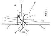
添付の図面を参照して、本開示は、内部容積11を画定するエンクロージャ8を備える、スピーカ10に関する。内部容積11は、空気などの気体で満たされていることが好ましいが、他の流体で満たされていてもよい。
With reference to the accompanying drawings, the present disclosure relates to a
スピーカ10は、少なくとも1つの音発生装置7をさらに備える。音発生装置7は、内部容積11を出入りする空気が動作可能に通過することができる通気導管15を画定する1つ以上の表面を含む。
The
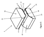
図1〜6に示す例示的な実施形態において、音発生装置7は、互いに隔てられた第1のブロック31と第2のブロック32とを備える。ブロック31は、ブロック32の表面13,22から隔てられた表面12,21を備え、これらの間に通気導管15が画定されている。
In the exemplary embodiment shown in FIGS. 1-6, the
特に、(空気が、エンクロージャ8の外部から通気導管15に入るように)内部容積1に向かう通気導管15への入口16を画定するように、表面21および22は、互いに隔てられて対向している。表面13および12は、それらの間に通気導管15の隙間18を画定するように、互いに隔てられて対向している。
In particular, the
好ましくは、表面21は、ブロック31の隣接する表面12に対して傾斜し、また、表面22は、ブロック32の隣接する表面13に対して傾斜している。より好ましくは、表面21,22は、隙間18に向かう方向に沿って、それらの間の距離が減少するように傾斜している。
Preferably, the
本明細書において、ある表面に対して「傾斜している」という用語は、リースやスロープを有するか、またはそのような表面に対して角度を形成していることを意味する。したがって、「傾斜している」という用語は、表面に対して「傾けられている」、「傾いている」、「角度がつけられている」、「傾斜している」、「横向きである」、「曲げられている」、「湾曲している」ことを包含する。 As used herein, the term "inclined" with respect to a surface means having a wreath or slope, or forming an angle with respect to such a surface. Therefore, the term "tilted" is "tilted", "tilted", "angled", "tilted", "sideways" with respect to the surface. , "Bent", "curved".
図1〜2および4〜5に示す例示的な実施形態において、表面21は、ブロック31の隣接する表面12に対して傾いており、表面22は、ブロック32の隣接する表面13に対して傾いている。
In the exemplary embodiments shown in FIGS. 1-2 and 4-5, the
図3に示す例示的な実施形態において、表面21は、内部容積11に向かって湾曲しており、表面22は、表面13に対して傾いている。
In the exemplary embodiment shown in FIG. 3, the
図6に示す例示的な実施形態において、表面21および22は、それぞれの表面12および13に対して湾曲している。
In the exemplary embodiment shown in FIG. 6, the
図1〜2および3に示す例示的な実施形態において、ブロック32の表面13は、ブロック31の対向面12に対して横方向に、それらの間の距離がエンクロージャ8の内部容積11に向かう方向に沿って増加するように配置されている。このようにして、隙間18は、そのような方向に沿って拡大している。
In the exemplary embodiments shown in FIGS. Arranged to increase along. In this way, the
図4〜5および6に示す例示的な実施形態において、表面12および13は、平行かつ平坦なトラクト部と、内部容積11に向かって湾曲した端部41と、を備える。特には、端部41は、内部容積11に向かって隙間18の端部が拡大するように湾曲している。
In the exemplary embodiments shown in FIGS. 4-5 and 6, surfaces 12 and 13 include parallel and flat tract portions and end
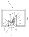
図9および10に示す実施形態において、音発生装置7は、互いに隔てられた、第1のブロック61と第2のブロック62とを備える。音発生装置7は、第1および第2のブロック62,63の間に配置されているがこれらとは隔てられた、第3のブロック63をさらに備える。
In the embodiments shown in FIGS. 9 and 10, the
ブロック61,62,63の隔てられた表面が、通気導管15を画定している。具体的に、ブロック63は、対向面64および65を含む。ブロック61は、表面64とは隔てられた表面66および67を含み、ブロック62は、表面65とは隔てられた表面68および69を含む。表面66および64は、それらの間に通気導管15の第1の隙間180を画定し、また、表面68および65は、それらの間に通気導管15の第2の隙間181を画定している。
Separated surfaces of
内部容積11に向かう通気導管15への入口16を画定するように、表面67および69は、互いに、かつ表面64および65と隔てられている。
The
図9〜10に示す例示的な実施形態において、ブロック63は、楕円形であるが、球形または長方形のような他の適切な形状を有していてもよい。
In the exemplary embodiment shown in FIGS. 9-10, the
表面67および69は、表面66および68に対してそれぞれ傾いており、具体的には、入口16から隙間180,181に向かってそれらの間の距離が減少するように傾けられている。このようにして、通気導管15は、入口16から隙間180および181に向かって減少している。
The
あるいは、表面67および69は、入口16から隙間180および181に向かってそれらの間の距離を減少させるように、湾曲していてもよい。
Alternatively, the
表面66および68は、ブロック63の対応する表面64,65からの距離が、内部容積11に向かう方向に沿って増加するように配置されている。このようにして、隙間180,181は、そのような方向に沿って拡大している。
The
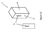
図13は、例えば、先に説明した実施形態の1つによる音発生装置7が取り付け可能であるエンクロージャ8を示しており、ここでは、空気流導管15への入口16が、エンクロージャ8の壁において利用可能となっている。図示のエンクロージャ8は、例えば、密封ボックス8とすることができる。
FIG. 13 shows, for example, an
図7〜8に示す例示的な実施形態において、音発生装置7は、ブロック33を備える。ブロック33は、円筒面24と、該円筒面24の対向する端部に配置された曲面35および36と、を含む。
In the exemplary embodiment shown in FIGS. 7-8, the
これらの表面24,35,36は、通気導管15を画定している。具体的に、曲面25は、内部容積11に向かう通気導管15への入口16を画定し、円筒面24は、通気導管15の中央の円筒孔19を画定し、曲面36は、内部容積11に向かう通気導管15の端部を画定している。
These
好ましくは、表面35は、円筒孔19から入口16に向かって通気導管15が拡大するように湾曲している。
Preferably, the
好ましくは、表面36は、円筒孔19から内部容積11に向かって通気導管15が拡大するように湾曲している。
Preferably, the
添付の図面を参照して、音発生装置7は、少なくとも1つの空気暴露電極(空気に曝された電極)1、4と、少なくとも1つの絶縁電極(絶縁された電極)2,3,70と、を含む複数の電極をさらに備える。電極2,3および70は、任意の適切な非導電性材料で絶縁することができる。
With reference to the accompanying drawings, the
好ましくは、各電極は、それ自体の延長された導電性表面を有する。電極は、任意の適切な形状を有することができる。例えば、これらに限定しないが、電極は、平坦な、直線状の、板状の、鋸歯状の、ストリップ状の、または細いワイヤ状の電極とすることができる。 Preferably, each electrode has its own extended conductive surface. The electrodes can have any suitable shape. For example, but not limited to these, the electrode can be a flat, linear, plate-like, serrated, strip-like, or thin wire-like electrode.
例えば、これらに限定しないが、空気暴露電極1〜4は、銅または他の導電体/半導体で作られていてもよく、絶縁電極2,3は、ポリイミド(例えば、カプトン)またはセラミックまたは任意の他の絶縁材料もしくは半導体材料に封入することができる。
For example, but not limited to these, the
スピーカ10は、少なくとも1つの空気暴露電極1,4と、少なくとも1つの絶縁電極2,3,70と、の間に電界を発生させ、該複数の電極に近接して通気導管15内にプラズマ100を動作可能に生成するように構成された、電圧源手段6をさらに備えている。
The
音発生装置7の複数の電極は、通気導管15内にプラズマ100を生成することに加えて、生成されたプラズマ100の、電界の変調に従う移動(エンクロージャ8の内部容積11に向かう移動または該内部容積11から離れる移動)を誘導するように、互いに、かつ通気導管15に対して配置されている。
In addition to generating
このようにして、移動イオンは、内部容積11に向かってまたは内部容積11から離れる向きに向けられた、通気導管15を通る空気流を強制的に流すように、周囲空気の粒子に運動量を伝達することができる。
In this way, the moving ions transfer momentum to the particles of ambient air so as to force an air flow through the
好ましくは、少なくとも1つの絶縁電極2,3,70は、通気導管15を画定する表面の対応する1つの下に配置され、少なくとも1つの空気暴露電極1,4は、少なくとも1つの絶縁電極2,3に対してオフセットして通気導管15内に配置されて、それらの間の電界が、プラズマのイオンの内部容積11への移動を誘導するようになっている。
Preferably, at least one insulating
図1〜6に示す例示的な実施形態において、音発生装置7は、ブロック31の表面12の下に配置された第1の絶縁電極2と、ブロック32の表面13の下に配置された第2の絶縁電極3と、を備える。
In the exemplary embodiment shown in FIGS. 1-6, the
絶縁電極2および3は、絶縁材料、例えば、誘電材料によって、対応する表面12および13から分離されている。例えば、図示の実施形態において、絶縁電極2および3は、対応するブロック31および32の絶縁材料内に封入されている。
The insulating
好ましくは、絶縁電極2および3は、それらが下に配置されている対応する表面12および13と平行である。それにも関わらず、このような実施形態の変形例において、絶縁電極は、空気暴露電極からより遠く離れた電界勾配を増加させるように傾斜していてもよい。
Preferably, the insulating
図1〜3に示す例示的な実施形態において、音発生装置7は、ブロック31の表面21上に配置された1つの空気暴露電極1をさらに備える。
In the exemplary embodiment shown in FIGS. 1-3, the
このようにして、空気暴露電極1は、絶縁電極2に対してオフセットして通気導管15内に配置されており、特に、空気暴露電極1は、通気導管15への入口16と、その下に絶縁電極2が配置されている表面12と、の間に配置されている。
In this way, the
図1〜2では、表面21が隣接する表面12に対して傾斜しているので、空気暴露電極1もまた、このような表面12に対して傾斜している。
In FIGS. 1 and 2, since the
図3では、表面21が表面12に対して湾曲しているので、該表面21上に配置された空気暴露電極1もまた、このような表面12に対して湾曲している。
In FIG. 3, since the
電圧源手段6は、空気暴露電極1と絶縁電極2、3との間に電界を発生させるように構成されている。
The voltage source means 6 is configured to generate an electric field between the
空気暴露電極1が絶縁電極2,3に対してオフセットされているので、電界線は、空気暴露電極1から離れて隙間18に入る。
Since the
このような電界線に続いて、生成されたプラズマ100は、少なくとも部分的に、その下に絶縁電極2が配置されている表面12に沿って延びる。絶縁電極3は、プラズマ100を上方に持ち上げ、プラズマ100が表面13にも少なくとも部分に沿って延びるようにする。電界の強さに応じて、絶縁電極3はまた、空気暴露電極1と組み合わせてプラズマ100の生成に寄与する。
Following such lines of electric field, the generated
プラズマ100のイオンは、最大の電界地点で、すなわち、空気暴露電極で生成される。電界線は、生成されたイオンが空気暴露電極1から離れて隙間18に向かうように、当該イオンの移動を誘導する。
The ions of the
移動イオンは、通気導管15を介して内部容積11に向けられた空気流を生成するような方法で、それらの運動量を周囲の空気粒子に移動させる。
The mobile ions transfer their momentum to the surrounding air particles in such a way as to generate an air flow directed at the
実際には、電界線に沿って移動している間、イオンは、隙間18に、したがって隙間18それ自体によってアクセス可能な内部容積11に向けて接線力成分を有する。したがって、プラズマ100は、空気流を、通気導管15を通過させて内部容積11に向けて送るように周囲の空気を押し出す。
In practice, while traveling along the lines of electric field, the ions have a tangential component in the
図4〜6に示す例示的な音発生装置7は、空気暴露電極1に加えて、空気暴露電極4を備える。
The
この追加の空気暴露電極4は、ブロック32の表面22に配置されている。
The additional
このように、空気暴露電極4は、絶縁電極3とオフセットして配置されている。特に、空気暴露電極4は、入口16と、その下に絶縁電極3が配置されている表面13と、の間に配置されている。
In this way, the
図4〜5では、表面22が隣接する表面13に対して傾斜しているので、空気暴露電極4もまたそのような表面13に対して傾斜している。
In FIGS. 4-5, since the
図6では、表面22が隣接する表面13に対して湾曲しているので、その上に配置された空気暴露電極4もまたそのような表面13に対して湾曲している。
In FIG. 6, since the
電圧源手段6は、空気暴露電極1,4の各々から絶縁電極2,3に向けられた電界を発生させるように構成されている。空気暴露電極1,4が絶縁電極2,3に対してオフセットされているので、電界線は、空気暴露電極1,4から離れて隙間18に入る。
The voltage source means 6 is configured to generate an electric field directed from each of the
これらの電界線に続いて、生成されたプラズマ100は、少なくとも部分的に、表面12および13に沿って延びる。さらに、絶縁電極3は、表面12に沿って生成されたプラズマ100を上方にリフトし、絶縁電極2は、表面13に沿って生成されたプラズマ100を下方にリフトする。このようにして、プラズマ100は、表面12,13に沿って広がり、これらの表面12,13の間の隙間18の残りの空間にも広がる。
Following these lines of electric field, the generated
プラズマ100のイオンは、最大の電界地点で、すなわち、空気暴露電極1および4で生成される。電界線は、生成されたイオンが空気暴露電極1,4から離れて隙間18に向かうように、該イオンの移動を誘導する。
The ions of the
移動イオンは、通気導管15を介して内部容積11に向けられた空気流を生成するように、それらの運動量を周囲の空気粒子に移動させる。
The mobile ions transfer their momentum to the surrounding air particles so as to generate an air flow directed to the
図9〜10に示す例示的な実施形態において、音発生装置7は、ブロック61の表面66の下に配置された第1の絶縁電極2と、ブロック62の表面68の下に配置された第2の絶縁電極3と、楕円形ブロック63の対向面64,65の下に配置された第3の絶縁電極70と、を備える。
In the exemplary embodiment shown in FIGS. 9-10, the
絶縁電極2,3および70は、対応するブロック61,62および63の絶縁材料内に封入されている。
The insulating
音発生装置7は、隙間180および181に隣接する通気導管15内に、入口16と、隙間180,181を画定する表面と、の間に配置された、1つの空気暴露電極1をさらに備える。
The
図9において、空気暴露電極1は、楕円形ブロック63上に配置された湾曲した電極である一方で、図10において、空気暴露電極1は、ブロック63の前に配置されたワイヤ状の電極である。
In FIG. 9, the
このように、空気にさらされた電極1は、絶縁電極2,3,70に対してオフセットして、通気導管15内に配置されている。
As described above, the
電圧源手段6は、空気暴露電極1と、絶縁電極2,3,70と、の間に電界を生成するように構成されている。
The voltage source means 6 is configured to generate an electric field between the
空気暴露電極1は、絶縁電極2,3,70に対してオフセットされているので、電界線は、空気暴露電極1から遠ざかる方向に向けられて隙間180および181に入る。
Since the
これらの電界線に続いて、生成されたプラズマ100は、少なくとも部分的に、その下に絶縁電極70が配置されている表面64および65に沿って延びる。絶縁電極2は、ププラズマ100が少なくとも部分的に表面66に沿って延びるように、プラズマ100を表面64から上方にリフトする。
Following these lines of electric field, the generated
絶縁電極3は、プラズマ100が少なくとも部分的に表面68に沿って延びるように、プラズマ100を表面65から下方にリフトする。電界の強さに応じて、絶縁電極2,3もまた、空気暴露電極1と組み合わせてプラズマ100の生成に寄与する。
The insulating
プラズマ100のイオンは、最大の電界地点で、すなわち、空気暴露電極1で生成される。電界線は、生成されたイオンが空気暴露電極1から遠ざかって隙間180,181に向かうように、該イオンの移動を誘発する。
The ions of the
移動イオンは、通気導管15を通過する空気流を生成するような方法で、それらの運動量を周囲の空気粒子に移動させる。
Mobile ions transfer their momentum to surrounding air particles in such a way as to generate airflow through the
実際には、電界線に沿って移動している間、イオンは、隙間180,181に、したがって隙間180,181それら自体によってアクセス可能な内部容積11に向けて接線力成分を有する。したがって、プラズマ100は、空気流を、通気導管15を通過させて内部容積11に向けて送るように周囲の空気を押し出す。
In practice, while traveling along the lines of electric field, the ions have a tangential component in the gaps 180,181, and thus towards the
図7〜8に示す例示的な実施形態において、音発生装置7は、円筒孔19を画定する表面14の下に配置された、円筒形の絶縁電極2を備える。具体的に、円筒形の電極2は、絶縁材料、例えば、誘電材料によって、対応する表面14と隔てられている。例えば、図示の実施形態において、電極2は、ブロック33の絶縁材料内に封入されている。
In the exemplary embodiment shown in FIGS. 7-8, the
音発生装置7は、曲面35上に配置された円形の空気暴露電極1をさらに備え、該円形の電極1は、円形の電極1の延長された導電面が円筒面14に対して湾曲して配置されている。
The
電圧源手段6は、円形の空気暴露電極1から円筒形の絶縁電極2に向けられた電界を発生させるように構成されている。円形の暴露電極1は、円筒形の電極2に対してオフセットされているので、電界線は、円形の空気暴露電極1から離れて円筒孔19に入る。
The voltage source means 6 is configured to generate an electric field directed from the circular
これらの電界線に続いて、生成されたプラズマ100は、少なくとも部分的に、その下に円筒形の絶縁電極2が配置されている表面14に沿って延びる。プラズマ100のイオンは、最大の電界地点で、すなわち、空気暴露電極1で生成される。電界線は、生成されたイオンが空気暴露電極1から離れて孔19に向かうように、該イオンの移動を誘発する。
Following these lines of electric field, the generated
移動イオンは、通気導管15を通過する空気流を発生させ、該空気流を内部容積11に向けるように、それらの運動量を周囲の空気粒子に移動させる。
The mobile ions generate airflows through the
実際には、電界線に沿って移動している間、イオンは、孔19に、したがって孔19それ自体によってアクセス可能な内部容積11に向けて接線力成分を有する。したがって、プラズマ100は、空気流を、通気導管15を通過させて内部容積11に向けて送るように周囲の空気を押し出す。
In practice, while traveling along the lines of electric field, the ions have a tangential component towards the
本発明に従うスピーカ10の電圧源手段6は、提供された電気音声信号25に応じて発生した電界を変調して、スピーカ10から対応する音声信号40を生成するようにさらに構成されている。
The voltage source means 6 of the
電界を変調するために使用される電気オーディオ信号25は、例えば、20Hz〜20kHzの間のオーディオ範囲内の周波数を有して、オーディオ信号40を生成してもよい。
The
電気オーディオ信号25は、20kHzを超える周波数を有して、少なくとも3MHzまでの周波数で超音波信号40を生成してもよい。
The
電界の大きさを変調することにより、生成されたプラズマ100が振動する。
By modulating the magnitude of the electric field, the generated
具体的には、変調された電界の大きさが増すと、プラズマ100の移動イオンが加速されるので、プラズマ100によって加えられた力が増大されて、周囲の空気が内部容積11に押し込まれる。
Specifically, as the magnitude of the modulated electric field increases, the moving ions of the
理解されるように、空隙導管15を通って内部容積11に向けられる空気流が加速することによって、エンクロージャ8の内部容積11を満たすガスが圧縮される。
As will be appreciated, the acceleration of the air flow directed at the
圧縮ガスは、プラズマ100によって内部容積11に押し込まれた空気に復元力を及ぼす(その逆も同様である)。
The compressed gas exerts a restoring force on the air pushed into the
変調された電界の大きさが減少すると、プラズマ100によって空気に及ぼされる押し込み力も、復元力によって克服されるまで減少する。
したがって、内部容積11に向かう空気流は、復元力がエンクロージャ8からその方向を逆転するまで減速し始める。
As the magnitude of the modulated electric field decreases, the pushing force exerted on the air by the
Therefore, the airflow towards the
スピーカ10からの音声信号40は、(図中の二重矢印によって示されるように)通気導管15を通って内部容積11を出入りする空気流のこのような変調から生じる。
The
エンクロージャ8の壁は、空気流の変調によって内部容積11内に生成され得る圧力波を相殺/吸収するのに適している。制振材料が、エンクロージャ8の壁の内部表面上に配置されていてもよい。
The walls of the
実際には、エンクロージャ8を満たすガスがばねのように作用し、通気導管15を通る変調された空気が移動する振動塊のように作用する。
In practice, the gas filling the
したがって、ホイッスル効果のように、通気導管15およびエンクロージャ8は、同調周波数が通気導管15のサイズ(長さ/幅)およびエンクロージャ8のサイズによって決まるオーディオ同調回路のように作用する。
Thus, like the whistle effect, the
同調周波数は、所望の動作周波数における利得を最大にするように選択することができる。実際には、エンクロージャ8および通気導管15それ自体によって実現されるオーディオ同調回路のQファクタを最大にするように、通気導管15および/またはエンクロージャ8のサイズを選択することができる。理解されるように、オーディオでは、Qファクタが低いほどよい。
The tuning frequency can be selected to maximize the gain at the desired operating frequency. In practice, the size of the
これは、例えば、通気導管15のサイズを小さく寸法決定する(その中の空気量を減少させることを意味する)ことによって達成することができる。
This can be achieved, for example, by resizing the
例えば、図1〜6に示す音発生装置7の寸法は、幅約6mm×高さ約45mmであり、隙間18が約約0.5〜3mm、好ましくは、2mm〜3mmである。この場合、エンクロージャ8は、約120×70×60mmであり得る。図13を参照すると、アクセススロット16の長さは、約45mmである。
For example, the dimensions of the
図7〜8に示す例示的な音発生装置7を参照すると、円筒孔19のサイズは、非常に小さく寸法決めされ得るので、プラズマ100は、孔19内のすべての空気を一度に移動させることができ、該孔19の中心を通って出てくるいかなる背圧波(生成された音声信号40を相殺し得る)を止めることができる。この音発生装置7は、特に、MEMsサイズで実現されるのに適している。したがって、その寸法は非常に小さく、大きくても数ミリメートルである。
With reference to the
超音波オーディオ信号40を生成する場合、エンクロージャ8はまた、オーディオQファクタを最大にするように、より小さい寸法とすることができる。
When generating the
図1〜6および9〜10に示す例示的な音発生装置7を参照すると、絶縁電極2に加えて絶縁電極3を使用することによって、隙間18,180,181内に生成されたプラズマは、少なくとも部分的に、このような隙間を画定する両対向面に沿って延びる。
Referring to the
このようにして、プラズマは、隙間18,180,181を通る空気流を円滑にガイドすることができ、これはすなわち、渦または乱気流を回避または少なくとも大幅に減少させることができる。
音声信号40は、通気導管15を通る空気流の変調によって生成されるので、空気流を改善することは、音圧/音量および音質が改善されることを意味する。
In this way, the plasma can smoothly guide the airflow through the
Since the
通気導管15を通る空気流は、空気暴露電極1を、隙間18を画定する表面12に対して傾斜させることによってさらに改善される。これは、面を横切って空気を引っ張る/押すことに一般に関連する乱流または加速減衰効果または境界層効果を回避または少なくとも大幅に低減する。
The air flow through the
同様の理由から、図1〜3に示すブロック32の表面13は、隙間18の延長線に沿って傾斜しており、これは、空気流を層状に保つのを助けることができる。
For the same reason, the
図4〜6に示す音発生装置7を参照すると、追加の空気暴露電極4は、図1〜3に示す音発生装置7と比較してプラズマ量を倍増させる(または、音発生装置7は、同じプラズマ量を発生させるがサイズが縮小される)。
Referring to the
追加の空気暴露電極4はまた、隙間18を通って空気流を流すために、移動イオンによって周囲の空気に及ぼされる押し込み力を増加させる。
The additional
空気暴露電極4は、表面13に対して傾斜している。これにより、通気導管15を通る空気流に対する乱流または加速減衰効果が回避されるか、または少なくとも大幅に低減される。
The
表面12,13の湾曲した端部41もまた、境界層効果の影響による減速を回避するか、または少なくとも低減することによって、隙間18を通る空気流を改善する。
The curved ends 41 of the
図9〜10に示す例示的な音発生装置7を参照すると、2つの隙間180,181の存在により、生成されるプラズマ100の量が増加する。
Referring to the
図7〜8に示す例示的な音発生装置7を参照すると、プラズマは、円筒形の孔19を通る空気流を円滑にガイドすることができるが、これは、プラズマが少なくとも部分的に円筒形の表面14に沿って延びているからである。
With reference to the
円形の空気暴露電極1を円筒形の表面14に対して傾斜させ、かつ曲面36を設けることによって、通気導管15を通る空気流がさらに改善される。
By inclining the circular
本発明によるスピーカ10の電圧源手段10は、通気導管15内にプラズマを動作可能に生成するのに十分なレベルの電界を発生させるように構成されている。空気をイオン化するために、電界は、空気(または通気導管15内の他のガス)の破壊電界よりも大きくなければならない。いったんイオン化されると、空気は、電界勾配の方向に移動する。
The voltage source means 10 of the
図11および12に示す例示的な実施形態を参照すると、電圧源手段6は、音発生装置7の1つ以上の空気暴露電極1,4と1つ以上の絶縁電極2,3との間に、供給電圧26を印加するように構成されている。
Referring to the exemplary embodiments shown in FIGS. 11 and 12, the voltage source means 6 is located between one or more
例えば、空気の破壊電界が約3kV/mmで誘電率が0.5mmであることを考慮すると、プラズマを生成するのに必要な供給電圧26の最小値は、約1.5kVである。最大電圧値は、誘電体の飽和を避けるために設定することができ、例えば、約30kVである。
For example, considering that the breaking electric field of air is about 3 kV / mm and the dielectric constant is 0.5 mm, the minimum value of the
図11に示す電圧源手段6は、キャリア周波数を有する源信号40を生成するように構成されている。
The voltage source means 6 shown in FIG. 11 is configured to generate a
電圧源手段6は、変圧器5(例えば、フライバックトランス5)をさらに含む。これは、源信号40を増幅し、プラズマ100を生成するのに必要な最小の電圧レベルよりも高い供給電圧26を生成するためのものである。
The voltage source means 6 further includes a transformer 5 (eg, a flyback transformer 5). This is to amplify the
好ましくは、発生音40の歪みを低減するためには、プラズマを最小レベルに維持するようにバイアスレベルを設定する必要がある。バイアスレベルは、音発生装置7の形状および電気的特性によって決定される。オーディオ電気信号25が存在しない場合、バイアスレベルはゼロになり得る。なお、ウォームアップ時間は必要としない。
Preferably, in order to reduce the distortion of the generated
バイアスレベルは、プッシュプル増幅器における中点のように、プラズマ力とエンクロージャ復元力とのバランス点を設定するので、プラズマがプッシュプルサイクル全体を通して力を直線的に制御することが保証される。プラズマは、空気の破壊点に達するまで点火しないので、最小レベル(上記の例では、1.5kV)は、押し込みを開始するための空気の破壊点を超えている。バイアス点は、最小電圧と最大電圧との中間にあり得る。言うなれば、0.5*(0kVmin−5kVmax)+1.5kV=4kVの範囲である。 The bias level sets the balance between the plasma force and the enclosure restoring force, much like the midpoint in a push-pull amplifier, ensuring that the plasma controls the force linearly throughout the push-pull cycle. Since the plasma does not ignite until the air break point is reached, the minimum level (1.5 kV in the above example) exceeds the air break point to initiate the indentation. The bias point can be between the minimum voltage and the maximum voltage. So to speak, it is in the range of 0.5 * (0 kVmin-5 kVmax) + 1.5 kV = 4 kV.
また、予め設定されたレベルに固定するのではなく、入来する音楽ストリームレベルに基づいてバイアスポイントを効果的に設定するプレディストーションアルゴリズム(Hammerstein Weiner)に基づいて、バイアスポイントを設定することが可能であり、かつより効率的である。そのようなアルゴリズムは、入力信号を取り込み、これが(スピーカのモデルに基づいて)どれだけのオーディオ歪を生成するのかを決定し、歪の逆を生成してそれを効果的に相殺する。 It is also possible to set the bias point based on the pre-distortion algorithm (Hammerstein Weiner), which effectively sets the bias point based on the incoming music stream level, rather than fixing it to a preset level. And more efficient. Such an algorithm captures the input signal, determines how much audio distortion it produces (based on the speaker model), and produces the reverse of the distortion to effectively offset it.
歪は、電圧、電流または光フィードバックなどの方法を利用して低減することもできる。プラズマ光強度レベルから光フィードバックを使用することにより、現在利用可能なスピーカに使用されているマイクロフォンフィードバックと比較してより迅速な応答時間が得られる。 Distortion can also be reduced by utilizing methods such as voltage, current or optical feedback. The use of optical feedback from plasma light intensity levels provides faster response times compared to the microphone feedback currently used in available speakers.
図11に示すように、源信号40は、変圧器5の一次側で、電気音声信号25によって変調され得る。あるいは、源信号40は、変圧器5の二次側で、電気音声信号25によって変調され得る。
As shown in FIG. 11, the
源信号40は、AC信号とすることができる。この場合、電圧源手段6は、電気音声信号25を用いて、このような信号40の振幅を変調するように構成されていることが好ましい。
The
源信号40は、パルス信号とすることができる。例えば、源信号40は、PWM信号であってもよいし、フライバックトランス5の共振点の周りで周波数を変化させるPFM(パルス周波数変調)によって生成されてもよい。実際に、変圧器5の勾配は、変圧器5の二次側でPWM信号のような信号を生成するために使用される。
The
源信号40はまた、直流高電圧を直接切り替えることによっても生成されるので、変圧器5の使用が回避される。これは、MWMsサイズにより適している。
Since the
パルス源信号40の場合、電圧源手段6は、電気音声信号25を使用することによって、このような信号40に対してパルス幅変調を実行するように構成されていることが好ましい。
In the case of the
好ましくは、源信号40のキャリア周波数は、15kHzを超え、好ましくは、18kHを超える。このように、源信号40は、可聴ノイズをもたらさない。
Preferably, the carrier frequency of the
キャリア周波数は、1または数百kHzであってもよい。例えば、キャリア周波数は、変圧器5の一次回路に対して共振することができ、例えば、約100kHzである。これは、共振点の一方側で他方側よりも押し込み力を大きくすることができ、より良好な低音応答が可能となる。 The carrier frequency may be one or several hundred kHz. For example, the carrier frequency can resonate with respect to the primary circuit of transformer 5, eg, about 100 kHz. This makes it possible to increase the pushing force on one side of the resonance point as compared to the other side, and a better bass response is possible.
例えば、キャリア周波数は、典型的には3MHzの値を有する場合があるプラズマのスパイク周波数(プラズママイクロ放電によって生じる)に一致するように選択することができる。このようにして、プラズマ100に影響を及ぼす電流スパイクを低減することができる。
For example, the carrier frequency can be selected to match the spike frequency of the plasma (caused by plasma microdischarge), which may typically have a value of 3 MHz. In this way, the current spikes that affect the
実際のスパイクプラズマ周波数でキャリア周波数を設定するために、スピーカ10は、キャリア周波数を、生成されたプラズマ100のスパイクの実際の周波数に対応する測定値に調整するように構成された制御手段30を備えることができる。
In order to set the carrier frequency at the actual spike plasma frequency, the
スピーカ10が超音波信号40を生成するために使用される場合、源信号40が超音波電気信号25によって変調されるように、対応するより高いキャリア周波数が選択される。あるいは、超音波電気信号25は、電源電圧信号40として直接使用され得る。
When the
通気導管15を介して空気を押し込むためにプラズマ100によって及ぼされる力は、源信号40の振幅/持続時間に依存する。
The force exerted by the
電圧源手段6は、供給電圧26に加えて、音発生装置7の複数の電極に直流電圧27を加えるようにさらに構成されている。このようにして押し込み力を増加させると、それによって生成される音声信号40の振幅が増加する。この場合、高電圧DCは、変圧器5の二次側にある必要があるため、個別のDC電源が必要となる。
The voltage source means 6 is further configured to apply a
押し込み力は、さらに、プラズマ濃度に依存する。プラズマ濃度を増加させるために、通気導管15内の空気に適切な粉塵/エアゾルをまくことができる。エアゾル/粉塵は、課せられた電界によって運ばれるイオン化粒子として作用し、これに沿って周囲の空気を引きずり込む。
The pushing force further depends on the plasma concentration. Appropriate dust / aerosol can be sprinkled on the air in the
図12に示す電圧源手段6は、通気導管15内にプラズマ100を生成するために、まず、複数の電極1〜4に電源電圧50を加えるように構成されている。プラズマ100の生成後、電圧源手段6は、電源電圧50から、例えば、PWM信号51に切り替えるように構成されている。
The voltage source means 6 shown in FIG. 12 is configured to first apply a
複数の電極1〜4に加えられたPWM信号51は、音声信号40を生成するために、電気音声信号25で変調される。
The
好ましくは、この場合、電源電圧50は、一連のナノ秒パルスを含む。プラズマの密度は、ナノ秒パルスエネルギーによって決定され、プラズマの押し込み力は、プラズマ密度およびPWM信号サイクルの両方に依存する。
Preferably, in this case, the
本発明によるスピーカ10は、複数の音発生装置7を備えることができる。
The
例えば、音発生装置7を直列に配置することによって、空気に及ぼされる全体的な力を増加させることができる。また、異なるプラズマ段階を位相化して波効果を生成することによって、力を増加するか、または音声信号40を導くことも可能である。
For example, by arranging the
例えば、図15は、直列に配置された、図10に示す例示的な実施形態に従う2つの音発生装置7を示す。
For example, FIG. 15 shows two
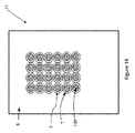
さらに、音発生装置7は、メッシュ/ハニカム構造となるように相互に配置されてもよい。例えば、図14は、図7〜8に示す例示的な実施形態に従う複数の音発生装置7を備えるスピーカ10を示す。
Further, the
ここで、図16を参照すると、さらに他の実施形態では、図14および15のそれぞれのように並列または直列に動作する複数の音発生装置の代わりに、音発生器を逆位相で動作させるように構成することができる。したがって、図16の例に示すように、空気暴露電極1および背面電極2’,3’との間の駆動信号は、空気暴露電極1と背面電極2’’,3’’との間の駆動信号と逆相であり得るので、上述の実施形態のように、空気が単に動的に押し込まれたり引っ張られたりするのではなく、空気が音発生装置を通って動的に空気押し込まれたり引っ張られたりする。図16には、単一の共通の電極1のみが示されているが、複数の電極が使用され得ることを理解されたい。同様に、電極2’,3’および2’’,3’’は、円筒形であってもよく、駆動信号に対して1つの接続のみを必要とする。
Here, referring to FIG. 16, in still another embodiment, the sound generators are operated in anti-phase instead of the plurality of sound generators operating in parallel or in series as in FIGS. 14 and 15, respectively. Can be configured in. Therefore, as shown in the example of FIG. 16, the drive signal between the
図示され上述された実施形態において、空気暴露電極は、エンクロージャの外面に向かって示されている。代替的な実施形態では、空気暴露電極および絶縁電極の位置を逆転させることができる、空気暴露電極がエンクロージャ内に配置されて接触から保護されていてもよい。このような実施形態では、スピーカがエンクロージャから空気を引き出し、エンクロージャが復元力を提供する。 In the embodiments illustrated and described above, the air exposure electrodes are shown towards the outer surface of the enclosure. In an alternative embodiment, air-exposed electrodes may be located within the enclosure to protect them from contact, which can reverse the positions of the air-exposed and insulated electrodes. In such an embodiment, the speaker draws air from the enclosure and the enclosure provides restoring force.
ブロック31,32,33および61,62は、図示された実施形態に示されているよりも多くエンクロージャ内に陥没していてもよく、場合によっては、発生したオゾンがエンクロージャから排出されないように、また、電極を接触から保護するように、隙間18または入口16を膜で覆うことができる。同様に、空気暴露電極を接地させ、かつ絶縁電極を高電圧に接続することも可能(その逆よりも)である。
スピーカは、オゾンを発生させること、およびいくつかの実施形態ではエンクロージャを気密にシールして放電を防止できることが理解されよう。しかしながら、オゾンを分散させるための他の技術、例えば、空気層の隙間18を100℃を超えて加熱すること、触媒層を使用すること、または、エンクロージャ内でヘリウムもしくはアルゴンなどのガスを使用することなどを利用することができる。
It will be appreciated that the speaker can generate ozone and, in some embodiments, airtightly seal the enclosure to prevent discharge. However, other techniques for dispersing ozone, such as heating the
Claims (12)
・内部容積(11)を画定する、エンクロージャ(8)と;
・少なくとも1つ音発生装置(7)であって、前記内部容積(11)を出入りする空気が動作可能に通過する通気導管(15)を画定する1つ以上の表面(12,13,21,22,14,35,36,64,65,66,67,68,69)を備え、さらに、少なくとも1つの空気暴露電極(1,4)および少なくとも1つの絶縁電極(2,3)を備える、音発生装置(7)と;
・前記少なくとも1つの空気暴露電極(1,4)と、前記少なくとも1つの絶縁電極(2,3,70)と、の間に電界を発生させ、前記複数の電極に近接して前記通気導管(15)内にプラズマ(100)を動作可能に生成するように構成された、電圧源手段(6)と;を備え、
・前記複数の電極は、前記発生した電界が前記生成されたプラズマ(100)を動作可能に誘導して、前記通気導管(15)を通る空気流を生じされるように、互いに、かつ前記通気導管(15)に対して配置されており;かつ
・前記電圧源手段(6)は、提供された電気音声信号(25)に応じて前記電界を変調することにより、前記通気導管(15)を通る空気流を変調して前記スピーカ(10)から対応する音声信号(40)を生成するように構成されている、スピーカ(10)。 The speaker (10):
• With the enclosure (8), which defines the internal volume (11);
At least one sound generator (7) having one or more surfaces (12, 13, 21,; 22,14,35,36,64,65,66,67,68,69), further comprising at least one air exposure electrode (1,4) and at least one insulating electrode (2,3). With sound generator (7);
An electric field is generated between the at least one air exposure electrode (1,4) and the at least one insulating electrode (2,3,70), and the ventilation conduit (the ventilation conduit (1,4) is close to the plurality of electrodes. The voltage source means (6) and; configured to operably generate the plasma (100) within 15) are provided.
The plurality of electrodes ventilate each other so that the generated electric field operably induces the generated plasma (100) to generate an air flow through the vent conduit (15). Arranged with respect to the conduit (15); and-the voltage source means (6) provides the vent conduit (15) by modulating the electric field in response to the provided electrical audio signal (25). A speaker (10) configured to modulate the airflow through it to generate a corresponding audio signal (40) from the speaker (10).
・前記少なくとも1つの空気暴露電極(1,4)は、前記少なくとも1つの絶縁電極(2,3,70)に対してオフセットして前記通気導管(15)内に配置されている、請求項1に記載のスピーカ(10)。 The at least one insulating electrode (2,3,70) corresponds to one or more surfaces (12,13,14,64,65,66,68) defining the ventilation conduit (15). Located under one;
1. The air exposure electrode (1,4) is arranged in the ventilation conduit (15) at an offset with respect to the at least one insulating electrode (2,3,70). The speaker (10) according to the above.
・前記少なくとも1つの絶縁電極は、前記第1の表面(12,64)の下に配置された第1の絶縁電極(2,70)と、前記第2の表面(13,66)の下に配置された第2の絶縁電極(3)と、を少なくとも含み、かつ
・前記少なくとも1つの空気暴露電極は、前記通気導管(15)内に前記第1の隙間(18,180)に隣接して配置された、第1の空気暴露電極(1)を少なくとも含む、請求項1に記載のスピーカ(10)。 The one or more surfaces defining the ventilation conduit (15) include a first surface (12,64) and a second surface (13,66), the first surface and the second surface. The surfaces of the are separated from each other so as to define a first gap (18,180) between them.
The at least one insulating electrode is placed under the first insulating electrode (2,70) arranged under the first surface (12,64) and under the second surface (13,66). Containing at least a second insulating electrode (3) arranged, and: • The at least one air exposure electrode is adjacent to the first gap (18,180) in the ventilation conduit (15). The speaker (10) according to claim 1, wherein the arranged speaker (10) includes at least a first air exposure electrode (1).
・前記少なくとも第1の空気暴露電極(1)は、前記通気導管(15)内に、前記第2の隙間(181)に隣接して配置されている、請求項5に記載のスピーカ(100)。 The one or more surfaces further include a third surface (65) and a fourth surface (68), the third surface and the fourth surface having a second gap between them. They are separated from each other so as to demarcate (181);
The speaker (100) according to claim 5, wherein at least the first air exposure electrode (1) is arranged in the ventilation conduit (15) adjacent to the second gap (181). ..
・前記複数の電極に電源電圧(50)を加えて、前記プラズマ(100)を動作可能に生成し;
・前記プラズマの生成後に、前記電源電圧(50)から直流電圧(51)に切り替え;かつ
・前記電気音声信号(25)で前記直流電圧(51)を変調するように構成されている、請求項1に記載のスピーカ(10)。 The voltage source means (6) is:
A power supply voltage (50) is applied to the plurality of electrodes to operably generate the plasma (100);
The power supply voltage (50) is switched to the DC voltage (51) after the plasma is generated; and the electric voice signal (25) is configured to modulate the DC voltage (51). The speaker (10) according to 1.
Applications Claiming Priority (3)
| Application Number | Priority Date | Filing Date | Title |
|---|---|---|---|
| GB1615702.6 | 2016-09-15 | ||
| GBGB1615702.6A GB201615702D0 (en) | 2016-09-15 | 2016-09-15 | Plasma speaker |
| PCT/EP2017/065309 WO2018050304A1 (en) | 2016-09-15 | 2017-06-21 | Plasma speaker |
Publications (3)
| Publication Number | Publication Date |
|---|---|
| JP2019533319A JP2019533319A (en) | 2019-11-14 |
| JP2019533319A5 JP2019533319A5 (en) | 2020-07-16 |
| JP6984899B2 true JP6984899B2 (en) | 2021-12-22 |
Family
ID=57288736
Family Applications (1)
| Application Number | Title | Priority Date | Filing Date |
|---|---|---|---|
| JP2018560488A Active JP6984899B2 (en) | 2016-09-15 | 2017-06-21 | Plasma speaker |
Country Status (6)
| Country | Link |
|---|---|
| US (1) | US10567887B2 (en) |
| EP (1) | EP3513576B1 (en) |
| JP (1) | JP6984899B2 (en) |
| CN (1) | CN109716791B (en) |
| GB (1) | GB201615702D0 (en) |
| WO (1) | WO2018050304A1 (en) |
Families Citing this family (5)
| Publication number | Priority date | Publication date | Assignee | Title |
|---|---|---|---|---|
| DE102017105401B4 (en) * | 2017-03-14 | 2019-01-31 | Tdk Electronics Ag | Apparatus for generating a non-thermal atmospheric pressure plasma |
| CN110381429B (en) * | 2019-08-23 | 2021-06-04 | 胡振强 | Directional plasma loudspeaker |
| CN110430515B (en) * | 2019-08-23 | 2021-03-23 | 苏州锐丰建声灯光音响器材工程安装有限公司 | Improved plasma loudspeaker |
| CN111988900A (en) * | 2020-07-21 | 2020-11-24 | 中国空气动力研究与发展中心低速空气动力研究所 | Application of plasma exciter and infrasonic wave generating method and device |
| CN117202058B (en) * | 2023-11-03 | 2024-03-26 | 地球山(苏州)微电子科技有限公司 | Pixel sounding unit, sounding method and digital loudspeaker |
Family Cites Families (11)
| Publication number | Priority date | Publication date | Assignee | Title |
|---|---|---|---|---|
| JPS5092755U (en) * | 1973-12-25 | 1975-08-05 | ||
| FR2506551A1 (en) * | 1981-05-21 | 1982-11-26 | Bondar Henri | METHOD AND DEVICE FOR TRANSFORMING A PERIODIC BF ELECTRICAL VOLTAGE INTO ACOUSTIC WAVES OR REVERSE |
| US5966452A (en) * | 1997-03-07 | 1999-10-12 | American Technology Corporation | Sound reduction method and system for jet engines |
| CN101232770A (en) * | 2008-01-25 | 2008-07-30 | 华中科技大学 | Device for medium to block discharging plasma body jet current |
| US8172547B2 (en) | 2008-01-31 | 2012-05-08 | The Boeing Company | Dielectric barrier discharge pump apparatus and method |
| JP2010141858A (en) * | 2008-12-15 | 2010-06-24 | Sony Corp | Sound generator |
| CN101778327B (en) * | 2010-01-07 | 2012-12-26 | 姚宗栋 | Electricity and sound conversion method and device |
| CN101820573B (en) * | 2010-04-30 | 2013-07-10 | 卢驭龙 | Control device for plasma loudspeaker and plasma loudspeaker |
| CN202218397U (en) * | 2011-09-27 | 2012-05-09 | 赵舸 | Plasma loudspeaker |
| JP5777540B2 (en) * | 2012-02-24 | 2015-09-09 | 株式会社オーディオテクニカ | Electroacoustic transducer |
| JP6099143B2 (en) * | 2013-06-12 | 2017-03-22 | 株式会社オーディオテクニカ | Electroacoustic transducer |
-
2016
- 2016-09-15 GB GBGB1615702.6A patent/GB201615702D0/en not_active Ceased
-
2017
- 2017-06-21 EP EP17732410.0A patent/EP3513576B1/en active Active
- 2017-06-21 WO PCT/EP2017/065309 patent/WO2018050304A1/en unknown
- 2017-06-21 JP JP2018560488A patent/JP6984899B2/en active Active
- 2017-06-21 CN CN201780029887.9A patent/CN109716791B/en active Active
- 2017-06-21 US US16/304,594 patent/US10567887B2/en active Active
Also Published As
| Publication number | Publication date |
|---|---|
| EP3513576A1 (en) | 2019-07-24 |
| EP3513576B1 (en) | 2020-10-21 |
| JP2019533319A (en) | 2019-11-14 |
| CN109716791B (en) | 2020-11-06 |
| WO2018050304A1 (en) | 2018-03-22 |
| CN109716791A (en) | 2019-05-03 |
| GB201615702D0 (en) | 2016-11-02 |
| US10567887B2 (en) | 2020-02-18 |
| US20190215616A1 (en) | 2019-07-11 |
Similar Documents
| Publication | Publication Date | Title |
|---|---|---|
| JP6984899B2 (en) | Plasma speaker | |
| US9558918B2 (en) | Cold plasma treatment devices and associated methods | |
| JP5011393B2 (en) | Ion transfer device | |
| US9100754B1 (en) | Electrically conductive membrane pump/transducer and methods to make and use same | |
| US20090022340A1 (en) | Method of Acoustic Wave Generation | |
| US20150208174A1 (en) | Electrically conductive membrane pump/transducer and methods to make and use same | |
| Bastien | Acoustics and gas discharges: applications to loudspeakers | |
| CN110741736A (en) | Apparatus for generating a non-thermal atmospheric pressure plasma | |
| US7889877B2 (en) | Device for generating a medium stream | |
| JP2019533319A5 (en) | ||
| US4460809A (en) | Process and device for converting a periodic LF electric voltage into sound waves | |
| JP5456531B2 (en) | Electroacoustic transducer and manufacturing method thereof | |
| US20220080459A1 (en) | Tunable electrostatic ion and fluid flow generator and electroacoustic transducer | |
| US10687148B2 (en) | Assembly comprising an electrostatic sound generator and a transformer | |
| EP3158774A1 (en) | Electrically conductive membrane pump/transducer and methods to make and use same | |
| EP3113582B1 (en) | Stabilized and homogenized source of non-thermal plasma | |
| Rodriguez | A review of the Plasma Loudspeaker (Ionic Loudspeaker): Principles of operation, general model and parts | |
| Jovic | A comparison between dynamic loudspeakers and plasma loudspeakers | |
| CN104507017A (en) | Optically controlled plasma loudspeaking system | |
| Krichtafovitch et al. | Efa loudspeakers | |
| Sergeev | Plasma-based Electroacoustic Actuator for Broadband Sound Absorption | |
| WO2012002924A1 (en) | Method for generating acoustic waves and device for carrying out said method | |
| Zeng et al. | Design and optimization of low frequency high power transducer | |
| Sergeev et al. | PLASMA-BASED ACOUSTIC METALAYER FOR SOUND CONTROL | |
| JP2009289561A (en) | Method and device for negative ion wind |
Legal Events
| Date | Code | Title | Description |
|---|---|---|---|
| A521 | Written amendment |
Free format text: JAPANESE INTERMEDIATE CODE: A523 Effective date: 20200604 |
|
| A621 | Written request for application examination |
Free format text: JAPANESE INTERMEDIATE CODE: A621 Effective date: 20200604 |
|
| A977 | Report on retrieval |
Free format text: JAPANESE INTERMEDIATE CODE: A971007 Effective date: 20210428 |
|
| A131 | Notification of reasons for refusal |
Free format text: JAPANESE INTERMEDIATE CODE: A131 Effective date: 20210511 |
|
| A521 | Written amendment |
Free format text: JAPANESE INTERMEDIATE CODE: A523 Effective date: 20210804 |
|
| TRDD | Decision of grant or rejection written | ||
| A01 | Written decision to grant a patent or to grant a registration (utility model) |
Free format text: JAPANESE INTERMEDIATE CODE: A01 Effective date: 20211116 |
|
| A61 | First payment of annual fees (during grant procedure) |
Free format text: JAPANESE INTERMEDIATE CODE: A61 Effective date: 20211117 |
|
| R150 | Certificate of patent or registration of utility model |
Ref document number: 6984899 Country of ref document: JP Free format text: JAPANESE INTERMEDIATE CODE: R150 |