JP6984632B2 - Pachinko machine - Google Patents
Pachinko machine Download PDFInfo
- Publication number
- JP6984632B2 JP6984632B2 JP2019082418A JP2019082418A JP6984632B2 JP 6984632 B2 JP6984632 B2 JP 6984632B2 JP 2019082418 A JP2019082418 A JP 2019082418A JP 2019082418 A JP2019082418 A JP 2019082418A JP 6984632 B2 JP6984632 B2 JP 6984632B2
- Authority
- JP
- Japan
- Prior art keywords
- effect
- display
- time
- symbol
- displayed
- Prior art date
- Legal status (The legal status is an assumption and is not a legal conclusion. Google has not performed a legal analysis and makes no representation as to the accuracy of the status listed.)
- Active
Links
Images


Description
本発明は、パチンコ機に代表される遊技機に関するものである。 The present invention relates to a gaming machine represented by a pachinko machine.
パチンコ機等の遊技機には、液晶表示装置等の表示装置が設けられた遊技機が知られている。この従来型の遊技機では、表示装置において図柄の変動表示が行われ、予め定められた図柄が停止表示されることで、遊技者に有利な当たり遊技が付与される。また、表示装置には、図柄以外にもキャラクタや風景等の様々な画像が表示され、多種多様な興趣演出を実行することで遊技の興趣向上を図っていた。 The gaming machine pachinko machine, a game machine display device such as a liquid crystal display device is provided that is known. In this conventional gaming machine, a variable display of a symbol is performed on a display device, and a predetermined symbol is stopped and displayed, so that a winning game advantageous to the player is given. In addition to the symbols, various images such as characters and landscapes are displayed on the display device, and a wide variety of hobby effects are performed to improve the hobby of the game.
しかしながら、さらなる興趣向上が求められている。 However , further improvement in interest is required.
本発明は、上記例示した問題点等を解決するためになされたものであり、遊技者の遊技に対する興趣を向上させることができる遊技機を提供することを目的としている。 The present invention has been made to solve the above-exemplified problems and the like, and an object of the present invention is to provide a gaming machine capable of improving a player's interest in playing a game.
この目的を達成するために請求項1記載の遊技機は、遊技者が操作可能な操作手段を有し、1の演出期間において、前記操作手段に対して予め定められた特定の操作内容の操作を行うことを促す演出態様を含む第1の演出態様を少なくとも含んで構成される所定の演出態様が複数回表示される特定演出を実行する特定演出実行手段と、前記第1の演出態様の表示中に前記操作手段に対して前記特定の操作内容の操作が行われたかを判別する判別手段と、その判別手段の判別結果に応じて、前記第1の演出態様の表示時間を少なくとも決定する表示時間決定手段と、前記所定の演出態様の表示中に前記第1の演出態様の表示時間が終了したことに基づいて、当該所定の演出態様の一部として第2の演出態様を表示させることが可能な第2演出態様表示手段と、を備え、前記表示時間決定手段は、前記特定演出における所定のタイミングで実行された前記第1の演出態様の表示中に前記判別手段により前記特定の操作内容の操作が行われたと判別された状況下において、新たに表示させる前記第1の演出態様の表示時間として予め定められた第1表示時間を設定可能な手段と、前記特定演出における所定のタイミングで実行された前記第1の演出態様の表示中に前記判別手段により前記特定の操作内容の操作が行われたと判別されなかった状況下において、新たに表示させる前記第1の演出態様の表示時間として前記第1表示時間よりも長い第2表示時間を設定可能な手段と、を備えたものであり、前記所定の演出態様は、当該所定の演出態様に含まれる前記第1の演出態様の表示中に前記特定の操作内容の操作が行われたか否かによらず、表示時間が共通となるように構成されており、前記特定演出は、前記特定演出の開始後における経過時間が予め定められた上限時間になったことに基づいて終了されるように構成されており、前記遊技機は、少なくとも前記所定の演出態様が表示され得る回数が予め定められた特定回数に設定された前記特定演出の実行中に表示される全ての前記第1の演出態様の表示中に前記特定の操作内容の操作が行われた場合に、前記上限時間が経過するよりも前に前記特定回数の前記所定の演出態様を表示させることが可能な構成である。
In order to achieve this object, the gaming machine according to
本発明の遊技機によれば、遊技者が操作可能な操作手段を有し、1の演出期間において、前記操作手段に対して予め定められた特定の操作内容の操作を行うことを促す演出態様を含む第1の演出態様を少なくとも含んで構成される所定の演出態様が複数回表示される特定演出を実行する特定演出実行手段と、前記第1の演出態様の表示中に前記操作手段に対して前記特定の操作内容の操作が行われたかを判別する判別手段と、その判別手段の判別結果に応じて、前記第1の演出態様の表示時間を少なくとも決定する表示時間決定手段と、前記所定の演出態様の表示中に前記第1の演出態様の表示時間が終了したことに基づいて、当該所定の演出態様の一部として第2の演出態様を表示させることが可能な第2演出態様表示手段と、を備え、前記表示時間決定手段は、前記特定演出における所定のタイミングで実行された前記第1の演出態様の表示中に前記判別手段により前記特定の操作内容の操作が行われたと判別された状況下において、新たに表示させる前記第1の演出態様の表示時間として予め定められた第1表示時間を設定可能な手段と、前記特定演出における所定のタイミングで実行された前記第1の演出態様の表示中に前記判別手段により前記特定の操作内容の操作が行われたと判別されなかった状況下において、新たに表示させる前記第1の演出態様の表示時間として前記第1表示時間よりも長い第2表示時間を設定可能な手段と、を備えたものであり、前記所定の演出態様は、当該所定の演出態様に含まれる前記第1の演出態様の表示中に前記特定の操作内容の操作が行われたか否かによらず、表示時間が共通となるように構成されており、前記特定演出は、前記特定演出の開始後における経過時間が予め定められた上限時間になったことに基づいて終了されるように構成されており、前記遊技機は、少なくとも前記所定の演出態様が表示され得る回数が予め定められた特定回数に設定された前記特定演出の実行中に表示される全ての前記第1の演出態様の表示中に前記特定の操作内容の操作が行われた場合に、前記上限時間が経過するよりも前に前記特定回数の前記所定の演出態様を表示させることが可能な構成である。 According to the gaming machine of the present invention, an effect mode in which a player has an operation means that can be operated and encourages the operation means to perform an operation of a predetermined specific operation content in one effect period. The specific effect executing means for executing the specific effect in which the predetermined effect mode including at least the first effect mode including the above is displayed a plurality of times, and the operation means during the display of the first effect mode. The predetermined means for determining whether or not the operation of the specific operation content has been performed, the display time determining means for determining at least the display time of the first effect mode according to the determination result of the determining means, and the predetermined means. A second effect mode display capable of displaying the second effect mode as a part of the predetermined effect mode based on the end of the display time of the first effect mode during the display of the effect mode. The display time determining means comprises means, and the display time determining means determines that the operation of the specific operation content is performed by the discriminating means during the display of the first effect mode executed at a predetermined timing in the specific effect. A means capable of setting a predetermined first display time as a display time of the first effect mode to be newly displayed under the above-mentioned situation, and the first one executed at a predetermined timing in the specific effect. In a situation where it is not determined by the discriminating means that the operation of the specific operation content has been performed during the display of the effect mode, the display time of the first effect mode to be newly displayed is longer than the first display time. long means capable of setting a second display time, which was equipped with the predetermined effect aspect, the specific operation contents in the display of the first representation embodiment included in the predetermined representation embodiment It is configured so that the display time is common regardless of whether or not the operation is performed, and the specific effect has reached a predetermined upper limit time after the start of the specific effect. The gaming machine is configured to be terminated based on the above, and the gaming machine is displayed during the execution of the specific effect in which at least the number of times the predetermined effect mode can be displayed is set to a predetermined specific number of times. When the operation of the specific operation content is performed during the display of the first effect mode, it is possible to display the predetermined effect mode a specific number of times before the upper limit time elapses. Ru Do configuration der.
これにより、遊技者の遊技に対する興趣を向上させることができるという効果がある。 This has the effect of improving the interest of the player in the game.
<第1実施形態>
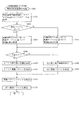
以下、本発明の第1の実施形態について、添付図面を参照して説明する。図1は、第1の実施形態におけるパチンコ機10の正面図であり、図2はパチンコ機10の遊技盤13の正面図であり、図3はパチンコ機10の背面図である。
<First Embodiment>
Hereinafter, the first embodiment of the present invention will be described with reference to the accompanying drawings. 1 is a front view of the
パチンコ機10は、図1に示すように、略矩形状に組み合わせた木枠により外殻が形成される外枠11と、その外枠11と略同一の外形形状に形成され外枠11に対して開閉可能に支持された内枠12とを備えている。外枠11には、内枠12を支持するために正面視(図1参照)左側の上下2カ所に金属製のヒンジ18が取り付けられ、そのヒンジ18が設けられた側を開閉の軸として内枠12が正面手前側へ開閉可能に支持されている。
As shown in FIG. 1, the
内枠12には、多数の釘や入賞口63,64等を有する遊技盤13(図2参照)が裏面側から着脱可能に装着される。この遊技盤13の前面を球が流下することにより弾球遊技が行われる。なお、内枠12には、球を遊技盤13の前面領域に発射する球発射ユニット112a(図12参照)やその球発射ユニット112aから発射された球を遊技盤13の前面領域まで誘導する発射レール(図示せず)等が取り付けられている。
A game board 13 (see FIG. 2) having a large number of nails, winning
内枠12の前面側には、その前面上側を覆う前面枠14と、その下側を覆う下皿ユニット15とが設けられている。前面枠14及び下皿ユニット15を支持するために正面視(図1参照)左側の上下2カ所に金属製のヒンジ19が取り付けられ、そのヒンジ19が設けられた側を開閉の軸として前面枠14及び下皿ユニット15が正面手前側へ開閉可能に支持されている。なお、内枠12の施錠と前面枠14の施錠とは、シリンダ錠20の鍵穴21に専用の鍵を差し込んで所定の操作を行うことでそれぞれ解除される。
On the front side of the
前面枠14は、装飾用の樹脂部品や電気部品等を組み付けたものであり、その略中央部には略楕円形状に開口形成された窓部14cが設けられている。前面枠14の裏面側には2枚の板ガラスを有するガラスユニット16が配設され、そのガラスユニット16を介して遊技盤13の前面がパチンコ機10の正面側に視認可能となっている。
The
前面枠14には、球を貯留する上皿17が前方へ張り出して上面を開放した略箱状に形成されており、この上皿17に賞球や貸出球などが排出される。上皿17の底面は正面視(図1参照)右側に下降傾斜して形成され、その傾斜により上皿17に投入された球が球発射ユニット112aへと案内される。また、上皿17の上方には、枠ボタン22が設けられている。この枠ボタン22は、例えば、後述する第3図柄表示装置81(図2参照)で表示される演出のステージを変更したり、スーパーリーチの演出内容を変更したりする場合などに、遊技者により操作される。
In the
ステージとは、第3図柄表示装置81に表示される各種演出に統一性を持たせた演出モードのことで、本パチンコ機10では「砂浜ステージ」,「深海ステージ」の2つのステージが設けられている。そして、後述する第1入球口64への入球(始動入賞)に伴って行われる変動演出やリーチ演出などの各種演出は、それぞれのステージに与えられたテーマに合わせて行われるように設計されている。ステージの変更は、変動演出が行われていない期間や高速変動中に遊技者によって枠ボタン22が操作された場合に行われ、枠ボタン22が操作される度に「砂浜ステージ」→「深海ステージ」→「砂浜ステージ」→・・・の順で繰り返し変更される。また、電源投入後の直後は、初期ステージとして「砂浜ステージ」が設定される。
The stage is an effect mode in which various effects displayed on the third
一方、第3図柄表示装置81には、ノーマルリーチ演出が開始された場合に、ノーマルリーチからスーパーリーチに発展させるときは、ノーマルリーチ中にスーパーリーチの演出態様の選択画面が表示されるように構成されており、その選択画面が表示されている間に、枠ボタン22が遊技者に操作されると、スーパーリーチ時の演出内容が変更される。
On the other hand, the third
前面枠14には、その周囲(例えばコーナー部分)に各種ランプ等の発光手段が設けられている。これら発光手段は、大当たり時や所定のリーチ時等における遊技状態の変化に応じて、点灯又は点滅することにより発光態様が変更制御され、遊技中の演出効果を高める役割を果たす。窓部14cの周縁には、LED等の発光手段を内蔵した電飾部29〜33が設けられている。パチンコ機10においては、これら電飾部29〜33が大当たりランプ等の演出ランプとして機能し、大当たり時やリーチ演出時等には内蔵するLEDの点灯や点滅によって各電飾部29〜33が点灯または点滅して、大当たり中である旨、或いは大当たり一歩手前のリーチ中である旨が報知される。また、前面枠14の正面視(図1参照)左上部には、LED等の発光手段が内蔵され賞球の払い出し中とエラー発生時とを表示可能な表示ランプ34が設けられている。
The
また、右側の電飾部32下側には、前面枠14の裏面側を視認できるように裏面側より透明樹脂を取り付けて小窓35が形成され、遊技盤13前面の貼着スペースK1(図2参照)に貼付される証紙等はパチンコ機10の前面から視認可能とされている。また、パチンコ機10においては、より煌びやかさを醸し出すために、電飾部29〜33の周りの領域にクロムメッキを施したABS樹脂製のメッキ部材36が取り付けられている。
Further, on the lower side of the illuminated
窓部14cの下方には、貸球操作部40が配設されている。貸球操作部40には度数表示部41と、球貸しボタン42と、返却ボタン43とが設けられている。パチンコ機10の側方に配置されるカードユニット(球貸しユニット)(図示せず)に紙幣やカード等を投入した状態で貸球操作部40が操作されると、その操作に応じて球の貸出が行われる。具体的には、度数表示部41はカード等の残額情報が表示される領域であり、内蔵されたLEDが点灯して残額情報として残額が数字で表示される。球貸しボタン42は、カード等(記録媒体)に記録された情報に基づいて貸出球を得るために操作されるものであり、カード等に残額が存在する限りにおいて貸出球が上皿17に供給される。返却ボタン43は、カードユニットに挿入されたカード等の返却を求める際に操作される。なお、カードユニットを介さずに球貸し装置等から上皿17に球が直接貸し出されるパチンコ機、いわゆる現金機では貸球操作部40が不要となるが、この場合には、貸球操作部40の設置部分に飾りシール等を付加して部品構成は共通のものとしても良い。カードユニットを用いたパチンコ機と現金機との共通化を図ることができる。
A ball
上皿17の下側に位置する下皿ユニット15には、その中央部に上皿17に貯留しきれなかった球を貯留するための下皿50が上面を開放した略箱状に形成されている。下皿50の右側には、球を遊技盤13の前面へ打ち込むために遊技者によって操作される操作ハンドル51が配設され、かかる操作ハンドル51の内部には球発射ユニット112aの駆動を許可するためのタッチセンサ51aと、押下操作している期間中には球の発射を停止する押しボタン式の打ち止めスイッチ51bと、操作ハンドル51の回動操作量を電気抵抗の変化により検出する可変抵抗器(図示せず)とが内蔵されている。操作ハンドル51が遊技者によって右回りに回転操作されると、タッチセンサ51aがオンされると共に可変抵抗器の抵抗値が操作量に対応して変化し、操作ハンドル51の回動操作量に応じて変化する可変抵抗器の抵抗値に対応した強さで球が発射され、これにより遊技者の操作に対応した飛び量で遊技盤13の前面へ球が打ち込まれる。また、操作ハンドル51が遊技者により操作されていない状態においては、タッチセンサ51aおよび打ち止めスイッチ51bがオフとなっている。
In the
下皿50の正面視下方部には、下皿50に貯留された球を下方へ排出する際に操作するための球抜きレバー52が設けられている。この球抜きレバー52は、常時、右方向に付勢されており、その付勢に抗して左方向へスライドさせることにより、下皿50の底面に形成された底面口が開口して、その底面口から球が自然落下して排出される。かかる球抜きレバー52の操作は、通常、下皿50の下方に下皿50から排出された球を受け取る箱(一般に「千両箱」と称される)を置いた状態で行われる。下皿50の右方には、上述したように操作ハンドル51が配設され、下皿50の左方には灰皿53が取り付けられている。
A
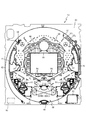
図2に示すように、遊技盤13は、正面視略正方形状に切削加工した木製のベース板60に、球案内用の多数の釘や風車およびレール61,62、一般入賞口63、第1入球口64、可変入賞装置65、可変表示装置ユニット80等を組み付けて構成され、その周縁部が内枠12の裏面側に取り付けられる。一般入賞口63、第1入球口64、可変入賞装置65、可変表示装置ユニット80は、ルータ加工によってベース板60に形成された貫通穴に配設され、遊技盤13の前面側から木ネジ等により固定されている。また、遊技盤13の前面中央部分は、前面枠14の窓部14c(図1参照)を通じて内枠12の前面側から視認することができる。以下に、主に図2を参照して、遊技盤13の構成について説明する。
As shown in FIG. 2, the
遊技盤13の前面には、帯状の金属板を略円弧状に屈曲加工して形成した外レール62が植立され、その外レール62の内側位置には外レール62と同様に帯状の金属板で形成した円弧状の内レール61が植立される。この内レール61と外レール62とにより遊技盤13の前面外周が囲まれ、遊技盤13とガラスユニット16(図1参照)とにより前後が囲まれることにより、遊技盤13の前面には、球の挙動により遊技が行われる遊技領域が形成される。遊技領域は、遊技盤13の前面であって2本のレール61,62と円弧部材70とにより区画して形成される略円形状の領域(入賞口等が配設され、発射された球が流下する領域)である。
An
2本のレール61,62は、球発射ユニット112a(図12参照)から発射された球を遊技盤13上部へ案内するために設けられたものである。内レール61の先端部分(図2の左上部)には戻り球防止部材68が取り付けられ、一旦、遊技盤13の上部へ案内された球が再度球案内通路内に戻ってしまうといった事態が防止される。外レール62の先端部(図2の右上部)には、球の最大飛翔部分に対応する位置に返しゴム69が取り付けられ、所定以上の勢いで発射された球は、返しゴム69に当たって、勢いが減衰されつつ中央部側へ跳ね返される。また、内レール61の右下側の先端部と外レール62の右上側の先端部との間には、レール間を繋ぐ円弧を内面側に設けて形成された樹脂製の円弧部材70がベース板60に打ち込んで固定されている。
The two
本パチンコ機10では、球が第1入球口64へ入球した場合に特別図柄(第1図柄)の抽選が行われ、球が普通入球口67を通過した場合に普通図柄(第2図柄)の抽選が行われる。第1入球口64への入球に対して行われる特別図柄の抽選では、特別図柄の大当たりか否かの当否判定が行われると共に、特別図柄の大当たりと判定された場合にはその大当たり種別の判定も行われる。特別図柄の大当たりになると、パチンコ機10が特別遊技状態へ移行すると共に、通常時には閉鎖されている特定入賞口65aが所定時間(例えば、30秒経過するまで、或いは、球が10個入賞するまで)開放され、その開放が16回(16ラウンド)繰り返される。その結果、その特定入賞口65aに多量の球が入賞するので、通常時より多量の賞球の払い出しが行われる。特別図柄の大当たり種別としては、「大当たりA」、「大当たりB」の2種類が設けられており、特別遊技状態の終了後には大当たり終了後の付加価値として、これらの大当たり種別に応じた遊技上の価値(遊技価値)が遊技者に付与される。
In the
また、特別図柄(第1図柄)の抽選が行われると、第1図柄表示装置37において特別図柄の変動表示が開始されて、所定時間(例えば、7秒〜90秒など)が経過した後に、抽選結果を示す特別図柄が停止表示される。第1図柄表示装置37において変動表示が行われている間に球が第1入球口64へ入球すると、その入球回数は最大4回まで保留され、その保留球数が第1図柄表示装置37により示されると共に、第3図柄表示装置81においても示される。第1図柄表示装置37において変動表示が終了した場合に、第1入球口64についての保留球数が残っていれば、次の特別図柄の抽選が行われると共に、その抽選に応じた変動表示が開始される。なお、パチンコ機10が特別遊技状態へ移行すると開閉される特定入賞口65aは、第1入球口64の直ぐ下に設けられている。よって、特別遊技状態中は、遊技者が特定入賞口65aに入賞させようとして球を打つので、第1入球口64にも球が多く入球する。従って、殆どの場合、パチンコ機10が特別遊技状態に移行している間に、第1入球口64についての保留球数は最大(4回)になる。
Further, when the special symbol (first symbol) is drawn, the variable display of the special symbol is started on the first
一方、普通入球口67における球の通過に対して行われる普通図柄の抽選では、普通図柄の当たりか否かの当否判定が行われる。普通図柄の当たりになると、所定時間(例えば、0.2秒または1秒)だけ第1入球口64に付随する電動役物64aが開放され、第1入球口64へ球が入球し易い状態になる。つまり、普通図柄の当たりになると、球が第1入球口64へ入球し易くなり、その結果、特別図柄の抽選が行われ易くなる。
On the other hand, in the lottery of the normal symbol performed for the passage of the ball at the
また、普通図柄(第2図柄)の抽選が行われると、第2図柄表示装置83において普通図柄の変動表示が開始されて、所定時間(例えば、3秒や30秒など)が経過した後に、抽選結果を示す普通図柄が停止表示される。第2図柄表示装置83において変動表示が行われている間に球が普通入球口67を通過すると、その通過回数は最大4回まで保留され、その保留球数が第1図柄表示装置37により表示されると共に、第2図柄保留ランプ84においても示される。第2図柄表示装置83において変動表示が終了した場合に、普通入球口67についての保留球数が残っていれば、次の普通図柄の抽選が行われると共に、その抽選に応じた変動表示が開始される。
Further, when the lottery of the normal symbol (second symbol) is performed, the variable display of the normal symbol is started on the second
上述したように、特別図柄の大当たり種別としては、「大当たりA」、「大当たりB」の2種類が設けられている。 As described above, there are two types of special symbols, "big hit A" and "big hit B".
「大当たりA」、及び「大当たりB」になるといずれも、ラウンド数が16ラウンドの特別遊技状態(16R大当たり)となる。また、大当たり種別が「大当たりA」の場合は、大当たり終了後の付加価値としてパチンコ機10が特別図柄の高確率状態(特別図柄の確変中)へ移行する。この特別図柄の高確率状態は次に特別図柄の大当たりとなるまで継続する。一方、「大当たりB」の終了後は付加価値として特別図柄の抽選が100回終了するまで普通図柄の当たり確率がアップする。
In both cases of "big hit A" and "big hit B", the number of rounds is 16 rounds in a special gaming state (16R big hit). When the jackpot type is "big hit A", the
ここで、「特別図柄の高確率状態」とは、特別図柄の大当たり確率がアップした状態、いわゆる特別図柄の確率状態(特別図柄の確変中)をいい、換言すれば、特別遊技状態(16R大当たり)へ移行し易い遊技の状態のことである。対して、「特別図柄の高確率状態」でない場合を「特別図柄の低確率状態」といい、これは特別図柄の確変状態よりも大当たり確率が低い状態、即ち、特別図柄の大当たり確率が通常の状態(特別図柄の通常状態)のことを示す。また、「普通図柄の時短状態」(普通図柄の時短中)とは、普通図柄の当たり確率がアップして、第1入球口64へ球が入球し易い遊技の状態のことをいう。対して、「普通図柄の時短状態」でない時を「普通図柄の通常状態」といい、これは普通図柄の当たり確率が通常の状態(時短中よりも当たり確率が低い状態)のことを示す。
Here, the "high probability state of the special symbol" means a state in which the jackpot probability of the special symbol is increased, that is, the probability state of the so-called special symbol (during the probability change of the special symbol), in other words, the special gaming state (16R jackpot). ) Is a state of the game that is easy to shift to. On the other hand, the case where it is not the "high probability state of the special symbol" is called the "low probability state of the special symbol", which means that the jackpot probability is lower than the probability variation state of the special symbol, that is, the jackpot probability of the special symbol is normal. Indicates a state (normal state of a special symbol). Further, the "normal symbol time reduction state" (during the normal symbol time reduction) refers to a game state in which the probability of hitting the normal symbol is increased and the ball can easily enter the
上述したように、本実施形態における特別図柄の大当たりでは、大当たりの種別に関わらず大当たり時のラウンド数を共通とし、大当たりの種別に応じて大当たりの終了後に「特別図柄の高確率状態」となるか「普通図柄の時短状態」となるかを変えている。これに対して、大当たりの種別に応じてラウンド数を変えても良いし、大当たりの種別の一部のみラウンド数を変えても良い。また、例えば、大当たりの種別に応じて「普通図柄の時短状態」となる期間を変えてもよい。また、普通図柄の時短状態として、第1入球口64に付随する電動役物64aを開放する時間を長くしたり、1回の普通図柄の当たりで電動役物64aを開放する回数を増やしても良い。
As described above, in the jackpot of the special symbol in the present embodiment, the number of rounds at the time of the jackpot is common regardless of the type of the jackpot, and the "high probability state of the special symbol" is obtained after the end of the jackpot according to the type of the jackpot. It is changing whether it becomes "normal symbol time saving state". On the other hand, the number of rounds may be changed according to the type of jackpot, or the number of rounds may be changed only for a part of the type of jackpot. Further, for example, the period during which the "normal symbol time reduction state" may be obtained may be changed according to the type of jackpot. In addition, as a time saving state of the normal symbol, the time for opening the
遊技領域の正面視右側上部(図2の右側上部)には、発光手段である複数の発光ダイオード(以下、「LED」と略す。)37aと7セグメント表示器37bとが設けられた第1図柄表示装置37が配設されている。第1図柄表示装置37は、後述する主制御装置110で行われる各制御に応じた表示がなされるものであり、主にパチンコ機10の遊技状態の表示が行われる。複数のLED37aは、第1入球口64への入球(始動入賞)に伴って行われる特別図柄の抽選が実行中であるか否かを点灯状態により示すことによって変動表示を行ったり、変動終了後の停止図柄として、その特別図柄の抽選結果に応じた特別図柄(第1図柄)を点灯状態により示したり、第1入球口64に入球された球のうち変動が未実行である球(保留球)の数である保留球数を点灯状態により示すものである。
A first symbol provided with a plurality of light emitting diodes (hereinafter abbreviated as "LED") 37a and a 7-
この第1図柄表示装置37において特別図柄(第1図柄)の変動表示が行われている間に球が第1入球口64へ入球した場合、その入球回数は最大4回まで保留され、その保留球数は第1図柄表示装置37により示されると共に、第3図柄表示装置81においても示される。なお、本実施形態においては、第1入球口64への入球は、最大4回まで保留されるように構成したが、最大保留回数は4回に限定されるものでなく、3回以下、又は、5回以上の回数(例えば、8回)に設定しても良い。
If a ball enters the
7セグメント表示器37bは、大当たり中のラウンド数やエラー表示を行うものである。なお、LED37aは、それぞれのLEDの発光色(例えば、赤、緑、青)が異なるよう構成され、その発光色の組み合わせにより、少ないLEDでパチンコ機10の各種遊技状態(特別図柄の高確率状態や、普通図柄の時短中など)を表示することができる。また、LED37aには、変動終了後の停止図柄として特別図柄の抽選結果が大当たりであるか否かが示されるだけでなく、大当たりである場合はその大当たり種別(大当たりA、大当たりB)に応じた特別図柄(第1図柄)が示される。
The 7-
また、遊技領域には、球が入賞することにより5個から15個の球が賞球として払い出される複数の一般入賞口63が配設されている。また、遊技領域の中央部分には、可変表示装置ユニット80が配設されている。可変表示装置ユニット80には、液晶ディスプレイ(以下単に「表示装置」と略す。)で構成された第3図柄表示装置81と、LEDで構成された第2図柄表示装置83とが設けられている。この可変表示装置ユニット80には、第3図柄表示装置81の外周を囲むようにして、センターフレーム86が配設されている。
Further, in the game area, a plurality of general winning
第3図柄表示装置81は、第1図柄表示装置37の表示に応じた装飾的な表示を行うものである。例えば、第1入球口64へ球が入球(始動入賞)すると、それをトリガとして、第1図柄表示装置37において特別図柄(第1図柄)の変動表示が実行される。更に、第3図柄表示装置81では、その特別図柄の変動表示に同期して、その特別図柄の変動表示に対応する第3図柄の変動表示が行われる。
The third
第3図柄表示装置81は、8インチの液晶ディスプレイで構成されるものであり、後述する表示制御装置114によって表示内容が制御されることにより、例えば左、中及び右の3つの図柄列が表示される。各図柄列は複数の図柄によって構成され、これらの図柄が図柄列毎に縦スクロールして第3図柄表示装置81の表示画面上にて第3図柄が可変表示されるようになっている。本実施形態では、主制御装置110の制御に伴った遊技状態の表示が第1図柄表示装置37で行われるのに対して、第3図柄表示装置81はその第1図柄表示装置37の表示に応じた装飾的な表示が行われる。なお、表示装置に代えて、例えば、リール等を用いて第3図柄表示装置81を構成するようにしても良い。
The third
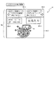
ここで、図4を参照して、第3図柄表示装置81の表示内容について説明する。第3図柄(第1特別図柄または第2特別図柄)は、「0」から「9」の数字を模した10種類の特別図柄によりそれぞれ構成されている。また、本実施形態のパチンコ機10においては、後述する主制御装置110による抽選結果が大当たりであった場合に、同一の主図柄が揃う(例えば「777」)変動表示が行われ、その変動表示が終わった後に大当たりが発生するよう構成されている。
Here, the display contents of the third
具体的には、主表示領域Dmは、左・中・右のそれぞれ3つの図柄列Z1,Z2,Z3が表示される。各図柄列Z1〜Z3には、上述した第3図柄が規定の順序で表示される。即ち、各図柄列Z1〜Z3には、数字の昇順または降順に主図柄が配列され、図柄列Z1〜Z3毎に周期性をもって上から下へとスクロールして変動表示が行われる。 Specifically, in the main display area Dm, three symbol columns Z1, Z2, and Z3 on the left, middle, and right are displayed. In each of the symbol rows Z1 to Z3, the above-mentioned third symbols are displayed in a specified order. That is, the main symbols are arranged in the ascending or descending order of the numbers in each of the symbol rows Z1 to Z3, and the variable display is performed by scrolling from top to bottom with periodicity for each of the symbol rows Z1 to Z3.
また、主表示領域Dmには、有効ラインL1上に第3図柄が停止表示される。その第3図柄が有効ライン上に大当たり図柄の組合せ(本実施形態では、同一の主図柄の組合せ)で揃って停止されれば、大当たりとして大当たり動画が表示される。 Further, in the main display area Dm, the third symbol is stopped and displayed on the effective line L1. If the third symbol is aligned and stopped on the effective line with a combination of jackpot symbols (in the present embodiment, the same combination of main symbols), the jackpot moving image is displayed as a jackpot.
本パチンコ機10では、奇数番号(1,3,5,7,9)で構成された主図柄は「確変図柄」に相当する。16R確変大当たりである「大当たりA」が発生する場合に同一の確変図柄の組み合わせが停止表示される可能性がある。また、偶数番号(2,4,6,8)で構成された主図柄は、「通常図柄」に相当する。16R通常大当たりである「大当たりB」が発生する場合には、必ず同一の通常図柄の組み合わせが停止表示される。また、「大当たりA」となった場合の一部でも、同一の通常図柄の組み合わせが停止表示される。これにより、通常図柄が停止表示された場合にも、大当たりAとなったことを期待させることができる。
In the
なお、第3図柄表示装置81における図柄の変動表示の態様は、上記のものに限定されることはなく任意であり、図柄列の数、図柄列における図柄の変動表示の方向、各図柄列の図柄数などは適宜変更可能である。また、第3図柄表示装置81にて変動表示される図柄は上記に限られることはなく、例えば図形やキャラクタ等の画像と数字とを組み合わせた図柄を第3図柄として構成してもよい。
The mode of the variable display of the symbol in the third
主表示領域Dmにおける正面視右上には、小表示領域Dm4が形成されている。この小表示領域Dm4は、第3図柄の変動表示を簡易的に表示させることが可能に構成されている。ここで、小表示領域Dm4において変動表示を実行する場合とは、例えば、主表示領域Dmにおいて、所定のキャラクタがアクションを行う演出や、枠ボタン22の押下を促す演出等の表示演出を実行している場合である。表示演出の実行中は、より大きな主表示領域Dmで演出を表示させることによって、より分かり易い演出を提供することができる。また、表示演出の実行中に、第3図柄の変動表示を小表示領域Dm4に簡易的に表示させておくことで、第3図柄の変動表示が継続していることを遊技者に対して容易に理解させることができる。
A small display area Dm4 is formed in the upper right of the front view in the main display area Dm. The small display area Dm4 is configured so that the variable display of the third symbol can be easily displayed. Here, when the variable display is executed in the small display area Dm4, for example, in the main display area Dm, a display effect such as an effect in which a predetermined character performs an action or an effect in which the
図4(a)に示すように、主表示領域Dmの下方には、副表示領域Dsが形成される。この副表示領域Dsには、図4(b)に示すように、黒色の円形からなる保留図柄が表示される。上述した通り、第1図柄表示装置37において変動表示が行われている間に球が第1入球口64へ入球すると、その入球回数は最大4回まで保留される。副表示領域Dsに対して表示される保留図柄は、保留された入球回数と同一の個数が表示される。本実施形態では、保留球数の最大値が4個に設定されているので、副表表示領域Dsには、保留図柄が最大4個表示される。
As shown in FIG. 4A, a sub-display region Ds is formed below the main display region Dm. As shown in FIG. 4B, a reserved symbol made of a black circle is displayed in the sub-display area Ds. As described above, if a ball enters the first
なお、本実施形態では、保留図柄の個数を保留球数に対応させて可変させていたが、保留球数を表示する方法はこれに限られるものではない。例えば、保留球数を数字で表示させる構成としてもよい。 In the present embodiment, the number of reserved symbols is changed according to the number of reserved balls, but the method of displaying the number of reserved balls is not limited to this. For example, the number of reserved balls may be displayed as a numerical value.
次に、図5から図7を参照して、本実施形態のパチンコ機10における表示演出の1種である連続変身演出について説明を行う。連続変身演出は、第3図柄の変動表示中にリーチ状態が発生した場合に実行される可能性がある表示演出である。ここで、リーチ状態とは、左図柄列Z1および右図柄列Z3が同一の数字からなる主図柄で停止表示され、中図柄列Z2のみが変動表示中である状態を指す。リーチ状態になると、中図柄列Z2が停止表示されることにより同一の図柄が3個揃う可能性があることを遊技者に認識させることができるので、遊技者の大当たりに対する期待感を向上させることができる。
Next, with reference to FIGS. 5 to 7, a continuous transformation effect, which is one of the display effects in the
連続変身演出は、リーチ状態が発生した後で、遊技者の大当たりに対する期待感をさらに向上させるために実行される演出であり、詳細については後述するが、主表示領域Dmに表示される男の子のキャラクタ811(図5(a)参照)が、時間の経過、又は遊技者の枠ボタン22に対する操作(押下)に応じて0〜n回(nは1以上の自然数)変身する(態様が変更される)演出である。この連続変身演出では、基本的にキャラクタ811の変身回数が多くなるほど大当たりとなる期待度が高くなる構成となっており、最大でキャラクタ811が5回変身する可能性がある演出である。
The continuous transformation effect is an effect performed to further improve the player's expectation for a big hit after the reach state occurs, and the details will be described later, but the boy's displayed in the main display area Dm. Character 811 (see FIG. 5A) transforms 0 to n times (n is a natural number of 1 or more) according to the passage of time or the operation (pressing) of the player's frame button 22 (the mode is changed). It is a production. In this continuous transformation effect, basically, the higher the number of transformations of the
なお、1の連続変身演出における最大の変身回数(連続変身演出の演出種別)は、連続変身演出を開始するよりも前に予め決定される。より具体的には、後述する変身演出選択テーブル222b(図15(a)参照)を用いた抽選により、1〜5回のいずれかの回数が決定される。この連続変身演出は、予め決定された上限回数の変身に成功するか、上限回数に到達するよりも前に、連続変身演出の演出種別毎に定められている演出時間となった場合に終了される。なお、本第1実施形態では、連続変身演出の最大の変身回数を、変身演出選択テーブル222bを用いた抽選により決定する構成としていた。即ち、連続変身演出の演出種別に応じて最大の変身回数が決定される構成としていたが、これに限られるものではなく、連続変身演出を開始する前に最大の変身回数を決定できる構成であればよい。具体的には例えば、前回の大当たりが終了した後の変動回数に応じて連続変身演出の上限回数を設定しても良い。変動回数が多いほど上限回数が多くなる構成とした場合は、特別図柄の抽選に外れ続けることに対して遊技者にメリットを感じさせることができるので、特別図柄の抽選に多くの回数連続して外れ続ける状態(所謂ハマり)が発生したとしても、遊技者の遊技に対するモチベーションが低下してしまうことを抑制できる。また、変動回数が少ないほど上限回数が多くなる構成とした場合は、短い間隔で大当たりに当選した(所謂連荘状態となった)場合に、賞球を獲得すること以外にもメリットを感じさせることができるので、遊技者をより楽しませることができる。更に、特定の範囲(例えば、変動回数が100〜200の範囲)で上限回数が多くなる構成とすれば、当該特定の範囲におけるパチンコ機10の稼働率を向上させることができる。
The maximum number of transformations (effect type of the continuous transformation effect) in the continuous transformation effect of 1 is determined in advance before the start of the continuous transformation effect. More specifically, any number of 1 to 5 times is determined by a lottery using the transformation effect selection table 222b (see FIG. 15A) described later. This continuous transformation effect ends when the transformation of the predetermined upper limit number of times is successful, or when the effect time specified for each effect type of the continuous transformation effect is reached before reaching the upper limit number of times. To. In the first embodiment, the maximum number of transformations of the continuous transformation effect is determined by lottery using the transformation effect selection table 222b. That is, the maximum number of transformations is determined according to the production type of the continuous transformation effect, but the configuration is not limited to this, and the maximum number of transformations can be determined before the continuous transformation effect is started. Just do it. Specifically, for example, the upper limit number of continuous transformation effects may be set according to the number of fluctuations after the end of the previous jackpot. If the upper limit is increased as the number of fluctuations increases, the player can feel the merit of continuing to be out of the special symbol lottery, so the special symbol lottery can be performed many times in a row. Even if a state of continuous disengagement (so-called addiction) occurs, it is possible to prevent the player's motivation for the game from being lowered. In addition, if the upper limit is increased as the number of fluctuations is smaller, if the jackpot is won at short intervals (so-called consecutive villa state), there are merits other than winning the prize ball. Because it can be done, the player can be more entertained. Further, if the upper limit number of times is increased in a specific range (for example, the number of fluctuations is in the range of 100 to 200), the operating rate of the
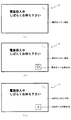
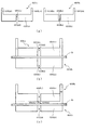
図5(a)は、この連続変身演出が開始される(連続変身演出に発展する)ことを示す変身発展態様が表示されている場合における第3図柄表示装置81の表示内容を示した図である。図5(a)に示した通り、変身発展態様が表示されると、主表示領域Dmの中央下部に男の子のキャラクタ811が表示されると共に、キャラクタ811の上方に、横長略長方形形状の表示領域HR1が表示される。この表示領域HR1には、「連続変身チャンス」という文字と、「変身回数が多い程期待度UP!」という文字とが表示される。なお、「連続変身チャンス」とは、連続変身演出を示す演出名である。表示領域HR1に表示されたこれらの文字により、遊技者に対して連続変身チャンス(連続変身演出)が開始されることを容易に理解させることができる。この変身発展態様は、1秒間表示され続け、1秒間が経過すると、連続変身演出が開始される。
FIG. 5A is a diagram showing the display contents of the third
なお、図5(a)に示した通り、変身発展態様が表示されると、主表示領域Dmにおける右上部分に、第3図柄の変動表示を簡易的に表示させるための小表示領域Dm4が形成される。これにより、変動表示が継続されていることを遊技者に対して容易に理解させることができる。この第3図柄の簡易表示は、連続変身演出、およびその後の発展演出の演出時間の間、継続する。 As shown in FIG. 5A, when the transformation development mode is displayed, a small display area Dm4 for simply displaying the variation display of the third symbol is formed in the upper right portion of the main display area Dm. Will be done. As a result, the player can easily understand that the variable display is continued. This simple display of the third symbol continues during the continuous transformation effect and the subsequent development effect.
変身発展態様の表示時間が経過した後で設定される連続変身演出では、枠ボタン22(図1参照)の押下を促す演出が表示される。具体的には、図5(b)に示した通り、主表示領域Dmにおけるキャラクタ811の左側に、横長略長方形形状の表示領域HR2が表示され、その表示領域HR2の内側に枠ボタン22を模した画像(PUSHボタンPB)が表示される。また、表示領域HR2の内部におけるPUSHボタンPBの下方には、時間の経過に応じて長さが短くなっていく、斜線が付されたスクロールバーSBが表示される。このスクロールバーSBは、枠ボタン22に対する操作を有効とする操作有効期間の残り時間を示したものである。本実施形態において、操作有効期間は5秒間が設定されるので、スクロールバーSBは、操作有効期間が開始されてから5秒間を掛けて長さが0になる。このスクロールバーSBを表示させることにより、遊技者に対して操作有効期間の残り時間を容易に認識させることができる。
In the continuous transformation effect set after the display time of the transformation development mode has elapsed, an effect urging the frame button 22 (see FIG. 1) to be pressed is displayed. Specifically, as shown in FIG. 5B, a horizontally long rectangular display area HR2 is displayed on the left side of the
なお、本実施形態では、操作有効期間が終了するまでの残り時間を、スクロールバーSBの長さによって表示(示唆)する構成としていたが、これに限られるものではない。例えば、残りの秒数をそのまま数字で表示させ、時間経過に応じてカウントダウンしていく構成とすることにより、残りの操作有効期間が遊技者にとって認識可能となるように構成してもよい。また、例えば、枠ボタン22を模したPUSHボタンPBの彩色を残りの操作有効期間に応じて可変させていくことにより、残り時間を遊技者に示唆する構成としてもよい。具体的には、例えば、残り時間が4秒以上の場合には、PUSHボタンPBの色を青色で表示し、残り時間が3秒以上、4秒未満の場合には、PUSHボタンPBの色を緑色で表示し、残り時間が2秒以上、3秒未満の場合には、PUSHボタンPBの色を黄色で表示し、残り時間が1秒以上、2秒未満の場合には、PUSHボタンPBの色をオレンジ色で表示し、残り時間が1秒未満の場合には、PUSHボタンPBの色を赤色で表示する構成としてもよい。また、操作有効期間が終了するまでの残り時間は、遊技者に必ずしも示唆する必要はない。操作有効期間の残り時間の示唆表示を省略することにより、表示制御を簡素化することができるので、パチンコ機10の処理負荷を軽減することができる。
In the present embodiment, the remaining time until the end of the operation valid period is displayed (suggested) by the length of the scroll bar SB, but the present invention is not limited to this. For example, the remaining number of seconds may be displayed as a numerical value as it is, and the countdown may be performed according to the passage of time so that the remaining operation valid period can be recognized by the player. Further, for example, the coloring of the PUSH button PB imitating the
表示領域HR2に加えて、キャラクタ811に対して正面視右側には、「PUSHで変身だ!」という文字が付された吹き出し型の表示領域HR3が表示される。これらの表示領域HR2、および表示領域HR3の表示内容により、遊技者に対して枠ボタン22を押下することでキャラクタ811が変身する(キャラクタ811の態様が変わる)可能性があることを認識させることができる。
In addition to the display area HR2, a balloon-type display area HR3 with the characters "Transformed by PUSH!" Is displayed on the right side of the front view with respect to the
また、表示領域HR3の右下側には、今回の連続変身演出においてキャラクタ811が変身した合計回数を示すための横長略長方形形状の表示領域HR4が形成される。この表示領域HR4には、例えば、図5(b)に示した通り、「変身×0」という文字が表示される。この文字は、変身が成功した回数に応じて更新されていく。具体的には、キャラクタ811が変身に1回成功すると、「変身×1」という文字に更新され、変身に2回成功すると、「変身×2」という文字に更新される。以下同様に、変身回数が3回となった場合に、「変身×3」という文字に更新され、変身回数が4回となった場合に、「変身×4回」という文字に更新され、変身回数が5回となった場合に、「変身×5回」という文字に更新される。この表示領域HR4に表示された文字を確認することで、遊技者は今回の連続変身演出における変身回数を容易に理解することができる。
Further, on the lower right side of the display area HR3, a horizontally long substantially rectangular display area HR4 for showing the total number of times the
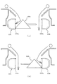
図6(a)は、設定された操作有効期間内に遊技者が枠ボタン22を押下し、キャラクタ811が変身に成功した場合における第3図柄表示装置81の表示態様の一例を示した図である。図6(a)に示した通り、枠ボタン22を操作有効期間内に押下すると、表示領域HR2において、PUSHボタンPBが押し込まれたような見た目の態様に変更され、操作有効期間が終了される。また、キャラクタ811の態様が、例えば、剣と盾を所持した冒険者を模した態様に変更される。また、表示領域HR4において、変身回数を示す文字に1が加算されて更新される。図6(a)では、「変身×1」に更新された場合を例示している。この変身に成功したことを報知する態様(成功報知態様)は1秒間継続し、当該成功報知態様が終了した後は、操作有効期間が再度設定される。そして、以降は、変身回数が上限に達するか、演出期間が経過するまで操作有効期間と、成功報知態様とが繰り返される。
FIG. 6A is a diagram showing an example of the display mode of the third
一方、図6(b)は、設定された有効期間内に枠ボタン22を遊技者が押下せず、且つ、変身に成功した場合を示した図である。図6(b)に示した通り、枠ボタン22を押下しなかった場合にも、最大の変身回数に達していなく、且つ、演出時間が所定期間以上残っている(残りの変動時間が所定の下限時間以上となっている)と判別された場合には、操作有効期間が経過したことを契機として成功報知態様が実行される。なお、詳細については後述するが、所定の下限時間は、連続変身演出の演出種別(最大の変身回数)に対応付けて変身演出選択テーブル222bに規定されている。
On the other hand, FIG. 6B is a diagram showing a case where the player does not press the
枠ボタン22を操作有効期間の間に押下した場合も、操作有効期間が経過するまで枠ボタン22の押下をしなかった場合も、最大の変身回数に達していなく、且つ、残りの変動時間が所定の下限時間以上となっていれば、成功報知態様が実行される。しかしながら、本実施形態では、全ての変身が、操作有効期間の経過を契機として実行された場合に、上限回数の変身(成功報知態様)が実行されるよりも前に、演出期間が経過する長さとなるように演出期間が設定されている。言い換えれば、上限回数分の操作有効期間(および上限回数分の成功報知態様の演出期間)の総和が、連続変身演出の演出期間よりも長くなるように操作有効期間が設定される。
Even if the
このように構成することで、1の連続変身演出において設定される各操作有効期間において、枠ボタン22を押下して操作有効期間が経過するよりも前にキャラクタ811を変身させなければ、演出種別毎に設定されている最大回数の変身を実行させることが不可能となる。また、操作有効期間が開始されてから、枠ボタン22が押下されるまでの期間が短いほど、その後に設定される操作有効期間の開始タイミングを早めることができるので、実行可能な変身の回数を、上限値の範囲内で増加させていくことができる。よって、上限回数の変身を行わせたい(なるべく多くの変身を行わせたい)と考える遊技者に対して、各操作有効期間において、積極的に枠ボタン22を押下させることができる。従って、遊技者の連続変身演出に対する参加意欲を向上させることができる。また、連続変身演出に参加しない(枠ボタン22を押下しない)遊技者が本パチンコ機10で遊技を行った場合には、本来は期待度が高い(変身の上限回数が多い)連続変身演出の場合にも、比較的少ない変身回数で連続変身演出の演出期間が経過してしまうことになる。これにより、少ない変身回数となる場合として、上限回数が多い(即ち、大当たりの期待度が高い)連続変身演出であるにもかかわらず演出期間が経過することにより少ない変身回数で終了してしまうケースを発生させることができる。これにより、少ない変身回数で連続変身演出が終了した場合でも、大当たりに対する期待感を高めることができる。
With this configuration, in each operation valid period set in 1 continuous transformation effect, if the
図7(a)は、成功報知態様において冒険者とは異なる態様に変身した場合の例を示した図である。図7(a)の例では、変身回数が3回目において、キャラクタ811がガンマンを模した態様に変身した場合を例示している。本第1実施形態では、このガンマンを模した態様や、上述した冒険者を模した態様等、変身回数に応じた複数の態様が用意されている。
FIG. 7A is a diagram showing an example in which the success notification mode is transformed into a mode different from that of the adventurer. In the example of FIG. 7A, the case where the
なお、本第1実施形態では、変身に成功した場合の態様を変身回数に応じて固定としていたが、これに限られるものではない。例えば、成功報知態様を行う毎に、キャラクタ811の態様を抽選等により決定してもよい。これにより、連続変身演出のバリエーションを多様化することができるので、遊技者の連続変身演出に対する興趣を向上させることができる。また、抽選等で成功報知態様の態様を決定する場合には、特別図柄の大当たりとなる変動表示の場合にのみ決定され得る態様や、特別図柄の大当たりとなる変動表示の場合に決定され易くなる態様、特別図柄の外れとなる変動表示の場合に決定され易くなる態様等を設ける構成としてもよい。このように構成することで、変身回数だけでなく、変身が成功した場合におけるキャラクタ811の表示態様にも注目して連続変身演出中の遊技を行わせることができる。
In the first embodiment, the mode when the transformation is successful is fixed according to the number of transformations, but the present invention is not limited to this. For example, the mode of the
図7(b)は、連続変身演出において、変身に失敗したことを報知する態様(失敗報知態様)が表示された場合における、第3図柄表示装置81の表示内容を示した図である。図7(b)に示した通り、変身に失敗した場合は、表示領域HR2のPUSHボタンPBが真っ二つに割れた態様で表示されると共に、キャラクタ811が落胆した表情で表示される。また、キャラクタ811の右上側には、「終了・・・」という文字が表示された表示領域HR5が表示される。これらの表示により、連続変身演出が終了した(変身回数が確定した)ことを認識させることができる。
FIG. 7B is a diagram showing the display contents of the third
なお、本第1実施形態では、連続変身演出が終了した後で、大当たりか否かの報知を行うための発展演出に移行する。発展演出には複数の種別が設けられており、残りの変動時間、および今回の特別図柄の抽選の当否に応じて1の発展演出の種別が選択され、実行される。この発展演出の詳細について、図8(a),(b)を参照して説明する。 In the first embodiment, after the continuous transformation effect is completed, the process shifts to the development effect for notifying whether or not the jackpot is a big hit. A plurality of types of development effects are provided, and one type of development effects is selected and executed according to the remaining fluctuation time and the success or failure of the lottery of the special symbol this time. The details of this development effect will be described with reference to FIGS. 8A and 8B.
まず、図8(a)は、連続変身演出から発展演出へと移行することを示す移行演出の表示態様を示した図である。図8(a)に示した通り、移行演出が実行されると、主表示領域Dmにキャラクタ811と、怪獣812とが睨み合う画像が表示されると共に、キャラクタ811と怪獣812との中間に、「VS」という文字が付された表示領域HR6が表示される。また、表示領域HR1に、「敵を倒せ!!」という文字が表示される。これらの表示内容により、キャラクタ811が敵(即ち、怪獣812)を倒すことにより、大当たりとなることを遊技者に対して容易に認識させることができる。
First, FIG. 8A is a diagram showing a display mode of a transition effect showing a transition from a continuous transformation effect to a development effect. As shown in FIG. 8A, when the transition effect is executed, an image in which the
また、図8(a)に示した通り、移行演出が実行されると、怪獣812の下方に表示領域HR7が表示される。この表示領域には、当該移行演出の終了後に実行される発展演出の期待度を示す1または複数の星印が表示される。図8(a)は、星印が2つ表示されている場合を例示している。この星印の個数は、連続変身演出における変身回数と同一の個数になる。図示については省略したが、星印の個数に連動して(即ち、連続変身演出における変身回数に連動して)、怪獣812の態様も可変される。即ち、星印の数が多いほど、怪獣812が弱そうな見た目(即ち、キャラクタ811が勝利し易そうな見た目)で表示され、星印の数が少ないほど、怪獣812が強そうな見た目(即ち、キャラクタ811が勝利し易そうな見た目)で表示される。このように構成することで、連続変身演出の結果(成功報知態様の表示回数)と、その後の発展演出とがリンクしているかのような印象を遊技者に対して抱かせることができる。よって、連続変身演出における変身回数(成功報知態様の表示回数)が大当たりとなる期待度を示唆していることを、遊技者に対してより容易に理解させることができる。
Further, as shown in FIG. 8A, when the transition effect is executed, the display area HR7 is displayed below the
なお、この移行演出、および上述の失敗報知態様(図7(b)参照)は、失敗報知態様が実行された時点における残りの変動時間に応じて表示期間の長さが可変される。これは、各発展演出の演出期間が固定(30秒、33秒、36秒、39秒、42秒、および45秒のいずれか)であるのに対して、連続変身演出が開始されてから最後の操作有効期間が終了するまでに要する期間は、遊技者が枠ボタン22を押下するタイミングに応じて可変するためである。よって、本実施形態では、操作有効期間が終了するタイミング(即ち、失敗報知態様の開始タイミング)において残りの変動時間を判別し、残りの変動時間で実行可能な最長の演出期間の発展演出を選択する。そして、残りの変動時間と、選択した発展演出の演出期間との差分の期間を用いて失敗報知態様、および移行演出を実行する構成としている。これにより、発展演出の演出時間のバリエーションを少なくすることができるので、発展演出を表示させるための各種データの容量を削減することができる。また、失敗報知態様、および移行演出の表示期間を、残りの変動時間に応じて動的に可変させることにより、発展演出の開始時点における残りの変動時間と、発展演出の演出時間とに齟齬が生じてしまうことを抑制することができる。即ち、残りの変動時間の方が長くなることで、発展演出が終了したにも拘わらず第3図柄の変動が停止しなかったり、逆に、発展演出の演出期間の方が長くなることで、第3図柄の変動が終了した時点で発展演出が終了しないという事態が生じてしまうことを防止することができる。従って、発展演出の終了タイミングと、第3図柄の変動表示の終了タイミングとを一致させることができるので、違和感の無い表示演出を提供することができる。なお、移行演出の演出時間が何秒に設定されたとしても、発展演出への切り替わりが不自然とならないように、移行演出が設定された期間の間は、図8(a)に示した態様に対して、大きな態様の変化が起こらないように構成している。即ち、図8(a)に例示した画像を静止画で表示させるか、または、キャラクタ811、およびキャラクタ812が自己の呼吸等に合わせて周期的に肩を上下させる程度の態様の変化に留まる(特別なアクションを行わない)ように構成される。これにより、移行演出の実行期間によらず、発展演出に切り替わる際の表示態様を同等とすることができるので、移行演出から発展演出に切り替わる際に、遊技者に対して見た目に違和感を抱かせてしまうことを抑制することができる。
In this transition effect and the above-mentioned failure notification mode (see FIG. 7B), the length of the display period is changed according to the remaining fluctuation time at the time when the failure notification mode is executed. This is the last time since the continuous transformation effect is started, while the effect period of each development effect is fixed (any of 30 seconds, 33 seconds, 36 seconds, 39 seconds, 42 seconds, and 45 seconds). This is because the period required for the operation valid period to end is variable according to the timing at which the player presses the
次に、図8(b)を参照して、発展演出の演出態様の経時変化について説明する。ここで、本第1実施形態では、発展演出として、当たり発展演出A〜F、および外れ発展演出A〜Fの12種類が設けられている。当たり、及び外れ発展演出Aは、共に演出期間が30秒の表示演出であり、当たり、及び外れ発展演出Bは、共に演出期間が33秒の表示演出である。以下同様に、当たり、および外れ発展演出C〜Fは、それぞれ36秒、39秒、42秒、および45秒の演出期間の表示演出として構成されている。連続変身演出における最後の操作有効期間の終了時には、残りの変動時間を超えない範囲で最も長い演出期間の発展演出が選択される。 Next, with reference to FIG. 8B, changes over time in the production mode of the development effect will be described. Here, in the first embodiment, 12 types of hit development effects A to F and off-development development effects A to F are provided as development effects. Both the hit and miss development effects A are display effects with an effect period of 30 seconds, and the hit and miss development effects B are both display effects with an effect period of 33 seconds. Similarly, the hit and miss development effects C to F are configured as display effects for the effect periods of 36 seconds, 39 seconds, 42 seconds, and 45 seconds, respectively. At the end of the last operation valid period in the continuous transformation effect, the development effect of the longest effect period is selected within the range not exceeding the remaining fluctuation time.
図8(b)に示した通り、本第1実施形態では、発展演出を実行するための元となる表示演出(ベース演出)のデータが用意されている。この元となる表示演出(ベース演出)は、表示期間が45秒間で構成されており、この元となる表示演出(ベース演出)の最初から、または途中から演出を実行することにより、対応する演出期間の発展演出を実行可能に構成されている。即ち、発展演出は、演出期間毎に別個の演出が用意されているのではなく、1のベース演出のデータを用いて各表示期間の発展演出のデータを生成する構成としている。このように構成することで、発展演出を実行するためのデータを削減することができるので、パチンコ機10の記憶容量を削減することができる。
As shown in FIG. 8B, in the first embodiment, the data of the display effect (base effect) which is the basis for executing the development effect is prepared. This original display effect (base effect) has a display period of 45 seconds, and by executing the effect from the beginning or in the middle of this original display effect (base effect), the corresponding effect is achieved. It is configured to be feasible for the development of the period. That is, the development effect is not prepared as a separate effect for each effect period, but is configured to generate the development effect data for each display period using the data of the base effect of 1. With such a configuration, it is possible to reduce the data for executing the development effect, so that the storage capacity of the
図8(b)に示した通り、ベース演出の最初の3秒間は、キャラクタ811がズーム表示された表示態様となる。そして、次の3秒間で、キャラクタ811が怪獣812に対して攻撃を行う演出が実行される。次いで、敵である怪獣812がズーム表示された表示態様が3秒間表示され、その後、怪獣812がキャラクタ811に対して攻撃を行う表示態様が3秒間に渡って表示される。その後、キャラクタ811の顔と、怪獣812の顔とがズーム表示される表示態様を3秒間に渡って表示させた後、キャラクタ811と怪獣812とが互いに激しく攻防を繰り広げる演出、および当該バトルの勝敗(結果)を報知する演出が30秒間に渡って表示される。このように、ベース演出は、大きく分けて、3秒間の表示態様5つと、30秒間の表示態様1つとに区切って構成されている。これらのいずれかの表示態様の区切り位置から表示演出を開始させることにより、発展演出を違和感なく表示させることができる。
As shown in FIG. 8B, the
より具体的には、図8(b)に示した通り、当たり、及び外れ発展演出Aを実行する場合には、ベース演出における15秒経過時以降の30秒間の表示態様を表示させることにより、演出期間が30秒の発展演出を実行する。同様に、当たり、及び外れ発展演出Bを実行する場合には、ベース演出における12秒経過時以降の33秒間の表示態様を表示させ、当たり、及び外れ発展演出Cを実行する場合には、ベース演出における9秒経過時以降の36秒間の表示態様を表示させる。また、当たり、及び外れ発展演出Dを実行する場合には、ベース演出における6秒経過時以降の39秒間の表示態様を表示させ、当たり、及び外れ発展演出Eを実行する場合には、ベース演出における3秒経過時以降の42秒間の表示態様を表示させる。一方、当たり、及び外れ発展演出Fを実行する場合には、ベース演出を最初から最後まで表示させることにより、45秒間の発展演出を実行する。 More specifically, as shown in FIG. 8B, when the hit and miss development effect A is executed, the display mode for 30 seconds after the lapse of 15 seconds in the base effect is displayed. A development production with a production period of 30 seconds is executed. Similarly, when the hit and miss development effect B is executed, the display mode for 33 seconds after the lapse of 12 seconds in the base effect is displayed, and when the hit and miss development effect C is executed, the base is displayed. The display mode for 36 seconds after the lapse of 9 seconds in the production is displayed. Further, when the hit and miss development effect D is executed, the display mode for 39 seconds after the lapse of 6 seconds in the base effect is displayed, and when the hit and miss development effect E is executed, the base effect is displayed. The display mode for 42 seconds after the lapse of 3 seconds in is displayed. On the other hand, when the hit and miss development effects F are executed, the development effects for 45 seconds are executed by displaying the base effects from the beginning to the end.
なお、ベース演出は、上述した怪獣812とバトルする態様のもの以外にも、複数の表示演出が用意されている。いずれの表示演出を元にして発展演出を実行するかについては、抽選により決定される。また、元となる各表示演出には、大当たり用の態様と、外れ用の態様とがそれぞれ用意されている。
In addition to the above-mentioned
また、本第1実施形態では、ベース演出を、連続変身演出の実行後以外でも転用可能に構成している。即ち、リーチ状態が発生した後、連続変身演出を介さずに、直接、または他の予告演出を介して、ベース演出を実行することにより、大当たりとなるか否かを報知可能に構成している。これにより、ベース演出の汎用性を高めることができるので、演出を実行するために必要なデータを削減することができる。また、連続変身演出を介さずにベース演出を実行する場合にも、実行する変動表示の変動時間に合わせてベース演出の最初から、あるいは途中から演出を実行可能に構成されている。これにより、異なる変動時間の変動表示に対しても、ベース演出を用いた演出を実行することができる。 Further, in the first embodiment, the base effect can be diverted even after the continuous transformation effect is executed. That is, after the reach state occurs, it is possible to notify whether or not it will be a big hit by executing the base effect directly or through another notice effect without going through the continuous transformation effect. .. As a result, the versatility of the base effect can be increased, and the data required to execute the effect can be reduced. Further, even when the base effect is executed without going through the continuous transformation effect, the effect can be executed from the beginning or the middle of the base effect according to the fluctuation time of the variable display to be executed. As a result, it is possible to execute an effect using the base effect even for the variable display of different variable times.
このように、本第1実施形態では、発展演出を表示させるためのベース演出を用意しておき、当該ベース演出に、演出の区切りが良い箇所を、発展演出の個数分だけ設定している。各区切り箇所は、残りの演出時間が各発展演出の演出時間に一致するように設定されている。これにより、各発展演出の演出時間に渡る、自然な見た目の表示演出を提供することができる。また、元となる1の演出態様から複数の演出時間が異なる発展演出を実行可能に構成することにより、発展演出の種別(演出時間)毎に、別々の演出データを用意する場合に比較して、各発展演出を表示させるために必要なデータを削減することができる。よって、パチンコ機10の記憶容量を削減することができる。
As described above, in the first embodiment, a base effect for displaying the development effect is prepared, and the number of places where the effect is well separated is set in the base effect for the number of the development effect. Each division point is set so that the remaining production time matches the production time of each development production. As a result, it is possible to provide a display effect having a natural appearance over the effect time of each development effect. Further, by configuring a plurality of development effects having different production times from the original one production mode so as to be feasible, as compared with the case where different production data are prepared for each type (production time) of the development production. , It is possible to reduce the data required to display each development effect. Therefore, the storage capacity of the
なお、本第1実施形態では、ベース演出を元にして、演出時間が異なる複数の発展演出を実行可能に構成していたが、これに限られるものではない。発展演出の演出時間に応じて、表示態様が全く異なる表示演出を実行する構成としてもよい。このように構成することで、発展演出を多様化させることができるので、遊技者の遊技に対する興趣を向上させることができる。 In the first embodiment, a plurality of development effects having different production times can be executed based on the base effect, but the present invention is not limited to this. A display effect having a completely different display mode may be executed according to the effect time of the development effect. With such a configuration, the development and production can be diversified, so that the player's interest in the game can be improved.
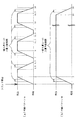
次に、図9(a),(b)を参照して、表示演出として連続変身演出が設定された場合における表示態様の経時変化について具体的に説明する。図9(a),(b)では、変身の上限回数が3回の連続変身演出が設定された場合を例にとって説明を行う。まず、図9(a)は、連続変身演出の実行中に枠ボタン22を遊技者が一度も押下しなかった場合における演出態様の計時変化を示した図である。
Next, with reference to FIGS. 9A and 9B, the change over time in the display mode when the continuous transformation effect is set as the display effect will be specifically described. In FIGS. 9A and 9B, a case where a continuous transformation effect in which the maximum number of transformations is 3 times is set will be described as an example. First, FIG. 9A is a diagram showing a timekeeping change of the effect mode when the player never presses the
図9(a)に示した通り、連続変身演出は、変動時間が60秒の変動演出(スーパーリーチ)の実行期間中に設定される。この連続変身演出が設定された変動表示において、変動開始から10秒間の間は、主表示領域Dmにおいて第3図柄の変動表示が実行される(図4(b)参照)。そして、変動開始から10秒が経過した時点で、リーチ状態が発生すると共に、連続変身演出に発展することを遊技者に示唆する変身発展態様(図5(a)参照)が1秒間に渡って表示される。 As shown in FIG. 9A, the continuous transformation effect is set during the execution period of the variation effect (super reach) with a variation time of 60 seconds. In the variation display in which the continuous transformation effect is set, the variation display of the third symbol is executed in the main display area Dm for 10 seconds from the start of the variation (see FIG. 4B). Then, when 10 seconds have passed from the start of the fluctuation, the reach state is generated and the transformation development mode (see FIG. 5A) that suggests to the player that the continuous transformation effect is developed is over 1 second. Is displayed.
変身発展演出の表示期間が経過すると、1回目の変身に対応する操作有効期間が設定される。枠ボタン22を遊技者が押下しない場合、この操作有効期間は5秒間に渡って(変動開始から16秒経過時まで)継続する。そして、操作有効期間が経過したことを契機として、1回目の成功報知態様が表示される。この成功報知態様は1秒間の間継続し、1秒が経過した時点(変動開始から17秒の時点)で、成功報知態様が終了すると共に、2回目の変身に対応する操作有効期間が設定される。この2回目の操作有効期間も、枠ボタン22の押下がなければ5秒間(変動開始後17秒〜22秒に渡って)継続する。そして、1秒間の成功報知態様が設定された後で、3回目の操作有効期間が設定される。この3回目の操作有効期間も、枠ボタン22の操作がなければ5秒間(変動開始後23秒〜28秒に渡って)継続する。そして、操作有効期間が終了する変動開始後28秒(残りの変動時間が32秒)のタイミングで、残りの変動時間が少ない(残りの変動時間が下限値として設定されている38秒未満である)と判別されて、変身の上限回数に到達していなくても、1秒間の失敗報知態様が設定される。即ち、変身の上限回数として3回が設定されていたにも拘わらず、変身回数が2回で連続変身演出が終了する。
When the display period of the transformation development effect elapses, the operation valid period corresponding to the first transformation is set. If the player does not press the
なお、成功報知態様を設定するのに十分な演出時間が残っているか否か判別するための条件は、後述する変身演出選択テーブル222b(図15(a)参照)によって規定されている。具体的には、最大(上限)の変身回数に応じて(即ち、連続変身演出の演出種別に応じて)、成功報知態様を設定可能な残りの変動時間の下限値(閾値)が規定されている。残りの変動時間が下限値を上回っている状態で操作有効期間が終了された場合は、変身の上限回数に到達していないことを条件として、成功報知態様を設定する。一方、残りの変動時間が下限値未満となってから操作有効期間が終了された場合には、変身の上限回数に到達しているか否かに拘らず、失敗報知態様を設定する。 The conditions for determining whether or not there is sufficient effect time remaining to set the success notification mode are defined by the transformation effect selection table 222b (see FIG. 15A), which will be described later. Specifically, the lower limit (threshold value) of the remaining fluctuation time in which the success notification mode can be set is defined according to the maximum (upper limit) number of transformations (that is, according to the production type of the continuous transformation effect). There is. If the operation valid period ends with the remaining fluctuation time exceeding the lower limit, the success notification mode is set on condition that the upper limit of the number of transformations has not been reached. On the other hand, when the operation valid period ends after the remaining fluctuation time becomes less than the lower limit value, the failure notification mode is set regardless of whether or not the upper limit number of transformations has been reached.
次に、図9(b)を参照して、変身の上限回数が3回の連続変身演出が設定され、遊技者が操作有効期間において積極的に枠ボタン22を押下した場合の演出態様の経時変化について説明する。
Next, with reference to FIG. 9B, a continuous transformation effect in which the maximum number of transformations is 3 is set, and the time lapse of the effect mode when the player positively presses the
図9(b)に示した通り、1回目の変身に対応する操作有効期間において、1秒経過時点(変動開始から12秒時点)で遊技者の枠ボタン22に対する押下を検出した場合には、操作有効期間が打ち切られて、1回目の成功報知態様が表示される。成功報知態様の表示期間である1秒が経過すると、2回目の変身に対応する操作有効期間が設定される(変動開始から13秒時点)。この2回目の操作有効期間において、1秒が経過した時点(変動開始から14秒時点)で再度、枠ボタン22に対する押下を検出した場合には、同様に操作有効期間が打ち切られて、2回目の成功報知態様が表示される。そして、成功報知態様の表示期間である1秒間が経過すると(変動開始から15秒時点)、3回目の操作有効期間が設定される。この3回目の操作有効期間が開始されてから2秒間が経過した時点(変動開始から17秒時点)で枠ボタン22に対する押下を検出した場合には、残りの変動時間が十分に(43秒間)残っているので、3回目の成功報知態様を表示させる。その後、3回目の成功報知態様の表示期間が経過したことを契機として、4回目の操作有効期間が設定される。この4回目の操作有効期間において、2秒が経過した時点(変動開始から20秒時点)で再度、枠ボタン22に対する押下を検出した場合には、既に今回の連続変身演出の上限の変身回数を実行済みであるため、失敗報知態様が設定される。
As shown in FIG. 9B, when the player's pressing on the
失敗報知態様(および失敗報知態様後の移行演出)の表示期間は、残りの変動時間である40秒間と、移行演出後に実行される発展演出の演出時間との差分に基づいて決定される。上述した通り、発展演出の種別は、残りの変動時間を超えない範囲で最も長い演出時間の種別が選択される。残りの変動時間が40秒の場合、失敗報知態様および移行演出の最短の表示期間である2秒間を加味すると、最長で38秒間を発展演出に用いることができる。しかしながら、上述した通り、発展演出の演出時間としては、30秒間、33秒間、36秒間、39秒間、42秒間、45秒間の6通りのみが用意されている。よって、38秒間よりも演出期間が短い36秒間の発展演出(発展演出C)が、今回の発展演出として設定される。そして、残りの変動時間である40秒と、発展演出Cの演出期間である36秒との差分の4秒間が、失敗報知態様、および移行演出の表示期間に設定される。具体的には、4秒間を等分して、失敗報知態様の表示期間、及び移行演出の表示期間としてそれぞれ2秒間が設定される。 The display period of the failure notification mode (and the transition effect after the failure notification mode) is determined based on the difference between the remaining fluctuation time of 40 seconds and the effect time of the development effect executed after the transition effect. As described above, as the type of development effect, the type of the longest effect time is selected within the range not exceeding the remaining fluctuation time. When the remaining fluctuation time is 40 seconds, a maximum of 38 seconds can be used for the development effect by adding the failure notification mode and the shortest display period of the transition effect of 2 seconds. However, as described above, as the production time of the development effect, only 6 types of 30 seconds, 33 seconds, 36 seconds, 39 seconds, 42 seconds, and 45 seconds are prepared. Therefore, the development effect (development effect C) for 36 seconds, which has a shorter effect period than 38 seconds, is set as the development effect this time. Then, 4 seconds, which is the difference between the remaining fluctuation time of 40 seconds and the effect period of the development effect C of 36 seconds, is set as the failure notification mode and the display period of the transition effect. Specifically, 4 seconds are equally divided, and 2 seconds are set as the display period of the failure notification mode and the display period of the transition effect.
このように、残りの変動時間と、発展演出の演出時間との差分を、失敗報知態様の表示期間と、移行演出の演出期間とにより吸収する構成とすることで、発展演出の演出時間のバリエーションが少なくても、変動停止のタイミングと発展演出の終了タイミングとを確実に一致させることができる。これにより、発展演出の演出時間のバリエーションを少なくすることができるので、発展演出を表示させるための各種データの容量を削減することができる。また、失敗報知態様、および移行演出の表示期間を、残りの変動時間に応じて動的に可変させることにより、発展演出の開始時点における残りの変動時間と、発展演出の演出時間とに齟齬が生じてしまうことを抑制することができる。即ち、残りの変動時間の方が長くなることで、発展演出が終了したにも拘わらず第3図柄の変動が停止しなかったり、逆に、発展演出の演出期間の方が長くなることで、第3図柄の変動が終了した時点で発展演出が終了しないという事態が生じてしまうことを防止することができる。従って、発展演出の終了タイミングと、第3図柄の変動表示の終了タイミングとを一致させることができるので、違和感の無い表示演出を提供することができる。 In this way, by absorbing the difference between the remaining fluctuation time and the production time of the development production by the display period of the failure notification mode and the production period of the transition production, the variation of the production time of the development production is made. Even if the number is small, the timing of the fluctuation stop and the timing of the end of the development effect can be surely matched. As a result, it is possible to reduce the variation in the production time of the development effect, and thus it is possible to reduce the capacity of various data for displaying the development effect. In addition, by dynamically changing the failure notification mode and the display period of the transition effect according to the remaining variation time, there is a discrepancy between the remaining variation time at the start time of the development effect and the effect time of the development effect. It is possible to suppress the occurrence. That is, since the remaining fluctuation time is longer, the fluctuation of the third symbol does not stop even though the development production is completed, or conversely, the production period of the development production is longer. It is possible to prevent a situation in which the development effect does not end when the change of the third symbol ends. Therefore, since the end timing of the development effect and the end timing of the variable display of the third symbol can be matched, it is possible to provide a display effect without a sense of discomfort.
図9(b)に示した通り、残りの変動時間が40秒の状態で失敗報知態様の開始タイミングとなった場合は、失敗報知態様、および移行演出の表示時間として各2秒間が設定される。そして、移行演出の終了後は、演出時間が36秒の発展演出Cが実行される。これにより、第3図柄の変動が停止されるタイミング(変動開始から60秒が経過したタイミング)と、発展演出の終了タイミングとを丁度一致させることができる。 As shown in FIG. 9B, when the start timing of the failure notification mode is reached with the remaining fluctuation time of 40 seconds, 2 seconds each is set as the display time of the failure notification mode and the transition effect. .. Then, after the transition effect is completed, the development effect C having an effect time of 36 seconds is executed. As a result, the timing at which the fluctuation of the third symbol is stopped (the timing at which 60 seconds have elapsed from the start of the fluctuation) and the end timing of the development effect can be exactly matched.
このように、遊技者が操作有効期間において枠ボタン22を積極的に押下することで、操作有効期間を短縮し、より多くの成功報知態様を表示させることができる。即ち、連続変身演出において、設定されている上限の変身回数まで変身を行わせ易くなるので、変身回数から演出の期待度をより正確に予測させることができる。よって、遊技者に対して積極的に枠ボタン22を押下させることができるので、連続変身演出に対する参加意欲を向上させることができる。また、連続変身演出に参加しない(枠ボタン22を押下しない)遊技者が本パチンコ機10で遊技を行った場合には、本来は期待度が高い(変身の上限回数が多い)連続変身演出の場合にも、比較的少ない変身回数で連続変身演出の演出期間が経過してしまうことになる。これにより、少ない変身回数となる場合として、上限回数が多い(即ち、大当たりの期待度が高い)連続変身演出であるにもかかわらず演出期間が経過することにより少ない変身回数で終了してしまうケースを発生させることができる。これにより、少ない変身回数で連続変身演出が終了した場合でも、大当たりに対する期待感を高めることができる。
In this way, by the player positively pressing the
なお、本実施形態では、失敗報知態様の表示時間と、移行演出の表示時間とを可変させることにより、残りの変動時間と、発展演出の演出時間とのギャップを吸収可能に構成していたが、これに限られるものではない。例えば、失敗報知態様の演出期間は固定とし、移行演出の表示時間のみを可変させる構成としてもよいし、逆に、失敗報知態様の演出期間のみを可変させる構成としてもよい。また、失敗報知態様、および移行演出の表示期間は固定とし、発展演出の一部の演出期間(例えば、第3図柄が確定表示されている期間等)を可変させる構成としてもよい。 In the present embodiment, by varying the display time of the failure notification mode and the display time of the transition effect, the gap between the remaining fluctuation time and the effect time of the development effect can be absorbed. , Not limited to this. For example, the effect period of the failure notification mode may be fixed and only the display time of the transition effect may be changed, or conversely, only the effect period of the failure notification mode may be changed. Further, the failure notification mode and the display period of the transition effect may be fixed, and a part of the effect period of the development effect (for example, the period in which the third symbol is definitely displayed) may be changed.
図2に戻って、説明を続ける。第2図柄表示装置83は、球が普通入球口67を通過することに伴って行われる普通図柄の抽選が実行中であるか否かを点灯状態により示すことによって変動表示を行ったり、変動終了後の停止図柄として、その普通図柄の抽選結果に応じた普通図柄(第2図柄)を点灯状態により示すものである。
Returning to FIG. 2, the explanation will be continued. The second
より具体的には、第2図柄表示装置83では、球が普通入球口67を通過する毎に、第2図柄としての「○」の図柄と「×」の図柄とを交互に点灯させる変動表示が行われる。パチンコ機10は、第2図柄表示装置83における変動表示が所定図柄(本実施形態においては「○」の図柄)で停止すると、第1入球口64に付随する電動役物64aが所定時間だけ作動状態となり(開放される)、その結果、第1入球口64に球が入り易い状態となるように構成されている。球が普通入球口67を通過した通過回数は最大4回まで保留され、その保留球数が上述した第1図柄表示装置37により表示されると共に第2図柄保留ランプ84においても点灯表示される。第2図柄保留ランプ84は、最大保留数分の4つ設けられ、第3図柄表示装置81の下方に左右対称に配設されている。
More specifically, in the second
なお、普通図柄(第2図柄)の変動表示は、本実施形態のように、第2図柄表示装置83において複数のランプの点灯と非点灯を切り換えることにより行うものの他、第1図柄表示装置37及び第3図柄表示装置81の一部を使用して行うようにしても良い。同様に、第2図柄保留ランプ84の点灯を第3図柄表示装置81の一部で行うようにしても良い。また、普通入球口67における球の通過は、第1入球口64と同様に、最大保留球数は4回に限定されるものでなく、3回以下、又は、5回以上の回数(例えば、8回)に設定しても良い。また、第1図柄表示装置37により保留球数が示されるので、第2図柄保留ランプ84により点灯表示を行わないものとしても良い。
It should be noted that the variable display of the normal symbol (second symbol) is performed by switching between lighting and non-lighting of a plurality of lamps in the second
可変表示装置ユニット80の下方には、球が入球し得る第1入球口64が配設されている。この第1入球口64へ球が入球すると遊技盤13の裏面側に設けられる第1入球口スイッチ(図示せず)がオンとなり、その第1入球口スイッチのオンに起因して主制御装置110で特別図柄の抽選がなされ、その抽選結果に応じた表示が第1図柄表示装置37のLED37aで示される。また、第1入球口64は、球が入球すると5個の球が賞球として払い出される入賞口の1つにもなっている。
Below the variable
第1入球口64の下方には可変入賞装置65が配設されており、その略中央部分に横長矩形状の特定入賞口(大開放口)65aが設けられている。パチンコ機10においては、主制御装置110で行われる特別図柄の抽選が大当たりとなると、所定時間(変動時間)が経過した後に、大当たりの停止図柄となるよう第1図柄表示装置37のLED37aを点灯させると共に、その大当たりに対応した第3図柄の停止図柄を第3図柄表示装置81に表示させて、大当たりの発生が示される。その後、通常時より多量の賞球の払い出しが行われる特別遊技状態(16ラウンドの大当たり)に遊技状態が遷移する。この特別遊技状態として、通常時には閉鎖されている特定入賞口65aが、所定時間(例えば、30秒経過するまで、或いは、球が10個入賞するまで)開放される。
A variable winning
この特定入賞口65aは、所定時間が経過すると閉鎖され、その閉鎖後、再度、その特定入賞口65aが所定時間開放される。この特定入賞口65aの開閉動作は、16回(16ラウンド)繰り返し可能にされている。この開閉動作が行われている状態が、遊技者にとって有利な特別遊技状態の一形態であり、遊技者には、遊技上の価値(遊技価値)の付与として通常時より多量の賞球の払い出しが行われる。
The
可変入賞装置65は、具体的には、特定入賞口65aを覆う横長矩形状の開閉板と、その開閉板の下辺を軸として前方側に開閉駆動するための大開放口ソレノイド(図示せず)とを備えている。特定入賞口65aは、通常時は、球が入賞できないか又は入賞し難い閉状態になっている。大当たりの際には大開放口ソレノイドを駆動して開閉板を前面下側に傾倒し、球が特定入賞口65aに入賞しやすい開状態を一時的に形成し、その開状態と通常時の閉状態との状態を交互に繰り返すように作動する。
Specifically, the variable winning
なお、特別遊技状態は上記した形態に限定されるものではない。特定入賞口65aとは別に開閉される大開放口を遊技領域に設け、第1図柄表示装置37において大当たりに対応したLED37aが点灯した場合に、特定入賞口65aが所定時間開放され、その特定入賞口65aの開放中に、球が特定入賞口65a内へ入賞することを契機として特定入賞口65aとは別に設けられた大開放口が所定時間、所定回数開放される遊技状態を特別遊技状態として形成するようにしても良い。
The special gaming state is not limited to the above-mentioned form. A large opening that opens and closes separately from the specific winning
遊技盤13の下側における左右の隅部には、証紙や識別ラベル等を貼着するための貼着スペースK1,K2が設けられ、貼着スペースK1に貼られた証紙等は、前面枠14の小窓35(図1参照)を通じて視認することができる。
Attachment spaces K1 and K2 for attaching a certificate stamp, an identification label, etc. are provided at the left and right corners on the lower side of the
更に、遊技盤13には、アウト口66が設けられている。いずれの入賞口63,64,65aにも入球しなかった球はアウト口66を通って図示しない球排出路へと案内される。遊技盤13には、球の落下方向を適宜分散、調整等するために多数の釘が植設されているとともに、風車等の各種部材(役物)が配設されている。
Further, the
図3に示すように、パチンコ機10の背面側には、制御基板ユニット90,91と、裏パックユニット94とが主に備えられている。制御基板ユニット90は、主基板(主制御装置110)と音声ランプ制御基板(音声ランプ制御装置113)と表示制御基板(表示制御装置114)とが搭載されてユニット化されている。制御基板ユニット91は、払出制御基板(払出制御装置111)と発射制御基板(発射制御装置112)と電源基板(電源装置115)とカードユニット接続基板116とが搭載されてユニット化されている。
As shown in FIG. 3, the
裏パックユニット94は、保護カバー部を形成する裏パック92と払出ユニット93とがユニット化されている。また、各制御基板には、各制御を司る1チップマイコンとしてのMPU、各種機器との連絡をとるポート、各種抽選の際に用いられる乱数発生器、時間計数や同期を図る場合などに使用されるクロックパルス発生回路等が、必要に応じて搭載されている。
In the
なお、主制御装置110、音声ランプ制御装置113及び表示制御装置114、払出制御装置111及び発射制御装置112、電源装置115、カードユニット接続基板116は、それぞれ基板ボックス100〜104に収納されている。基板ボックス100〜104は、ボックスベースと該ボックスベースの開口部を覆うボックスカバーとを備えており、そのボックスベースとボックスカバーとが互いに連結されて、各制御装置や各基板が収納される。
The
また、基板ボックス100(主制御装置110)及び基板ボックス102(払出制御装置111及び発射制御装置112)は、ボックスベースとボックスカバーとを封印ユニット(図示せず)によって開封不能に連結(かしめ構造による連結)している。また、ボックスベースとボックスカバーとの連結部には、ボックスベースとボックスカバーとに亘って封印シール(図示せず)が貼着されている。この封印シールは、脆性な素材で構成されており、基板ボックス100,102を開封するために封印シールを剥がそうとしたり、基板ボックス100,102を無理に開封しようとすると、ボックスベース側とボックスカバー側とに切断される。よって、封印ユニット又は封印シールを確認することで、基板ボックス100,102が開封されたかどうかを知ることができる。
Further, in the board box 100 (main control device 110) and the board box 102 (
払出ユニット93は、裏パックユニット94の最上部に位置して上方に開口したタンク130と、タンク130の下方に連結され下流側に向けて緩やかに傾斜するタンクレール131と、タンクレール131の下流側に縦向きに連結されるケースレール132と、ケースレール132の最下流部に設けられ、払出モータ216(図10参照)の所定の電気的構成により球の払出を行う払出装置133とを備えている。タンク130には、遊技ホールの島設備から供給される球が逐次補給され、払出装置133により必要個数の球の払い出しが適宜行われる。タンクレール131には、当該タンクレール131に振動を付加するためのバイブレータ134が取り付けられている。
The
また、払出制御装置111には状態復帰スイッチ120が設けられ、発射制御装置112には可変抵抗器の操作つまみ121が設けられ、電源装置115にはRAM消去スイッチ122が設けられている。状態復帰スイッチ120は、例えば、払出モータ216(図12参照)部の球詰まり等、払出エラーの発生時に球詰まりを解消(正常状態への復帰)するために操作される。操作つまみ121は、発射ソレノイドの発射力を調整するために操作される。RAM消去スイッチ122は、パチンコ機10を初期状態に戻したい場合に電源投入時に操作される。
Further, the
<第1実施形態における電気的構成について>
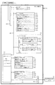
次に、図10を参照して、本パチンコ機10の電気的構成について説明する。図10は、パチンコ機10の電気的構成を示すブロック図である。
<Regarding the electrical configuration in the first embodiment>
Next, with reference to FIG. 10, the electrical configuration of the
主制御装置110には、演算装置である1チップマイコンとしてのMPU201が搭載されている。MPU201には、該MPU201により実行される各種の制御プログラムや固定値データを記憶したROM202と、そのROM202内に記憶される制御プログラムの実行に際して各種のデータ等を一時的に記憶するためのメモリであるRAM203と、そのほか、割込回路やタイマ回路、データ送受信回路などの各種回路が内蔵されている。なお、払出制御装置111や音声ランプ制御装置113などのサブ制御装置に対して動作を指示するために、主制御装置110から該サブ制御装置へ各種のコマンドがデータ送受信回路によって送信されるが、かかるコマンドは、主制御装置110からサブ制御装置へ一方向にのみ送信される。
The
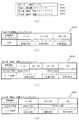
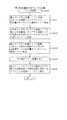
まず、ROM202の内容について、図11,12を参照して説明する。図11(a)に示すように、主制御装置110のROM202には、上記した固定値データの一部として、第1当たり乱数テーブル202a、第1当たり種別選択テーブル202b、第2当たり乱数テーブル202c、および変動パターン選択テーブル202dが少なくとも記憶されている。
First, the contents of the
第1当たり乱数テーブル202a(図示せず)は、後述する第1当たり乱数カウンタC1の大当たり判定値が記憶されているデータテーブルである。詳細については、第1当たり乱数カウンタC1の説明と共に後述するが、始動入賞に基づいて取得した第1当たり乱数カウンタC1の値が、第1当たり乱数テーブル202aに規定されているいずれかの判定値と一致した場合に、特別図柄の大当たりであると判別される。 The first hit random number table 202a (not shown) is a data table in which the jackpot determination value of the first hit random number counter C1 described later is stored. The details will be described later together with the description of the first random number counter C1, but the value of the first random number counter C1 acquired based on the start winning is any determination value specified in the first random number table 202a. If it matches with, it is determined that it is a big hit of a special symbol.
第1当たり種別選択テーブル202b(図11(b))は、大当たり種別を決定するための判定値が記憶されているデータテーブルであり、第1当たり種別カウンタC2の判定値が、各大当たり種別に対応付けて規定されている。具体的には、第1当たり種別カウンタC2の値が「0〜49」の範囲には、大当たりAが対応付けられて規定されている(図11(b)の202b1参照)。また、第1当たり種別カウンタC2の値が「50〜99」の範囲には、大当たりBが対応付けられて規定されている(図11(b)の202b2参照)。本実施形態のパチンコ機10では特別図柄の大当たりと判定された場合に、始動入賞に基づいて取得した第1当たり種別カウンタC2の値と、第1当たり種別選択テーブル202bとが比較され、第1当たり種別カウンタC2の値に対応する大当たり種別が選択される。
The first hit type selection table 202b (FIG. 11 (b)) is a data table in which determination values for determining the jackpot type are stored, and the determination value of the first hit type counter C2 is set to each jackpot type. It is specified in association with each other. Specifically, the jackpot A is associated with the range in which the value of the first hit type counter C2 is "0 to 49" (see 202b1 in FIG. 11B). Further, in the range where the value of the first hit type counter C2 is "50 to 99", the jackpot B is associated and defined (see 202b2 in FIG. 11B). In the
第2当たり乱数テーブル202c(図11(c)参照)は、普通図柄の当たり判定値が記憶されているデータテーブルである。具体的には、普通図柄の通常状態において、普通図柄の当たりとなる判定値として、「5〜28」が規定されている(図11(c)の202c1参照)。また、普通図柄の高確率状態において、普通図柄の当たりとなる判定値として、「5〜204」が規定されている(図11(c)の202c2参照)。本実施形態のパチンコ機10では、普通入球口67を球が通過することに基づいて取得される第2当たり乱数カウンタC4の値と、第2当たり乱数テーブル202cとを参照し、普通図柄の当たりであるか否かを判定している。
The second hit random number table 202c (see FIG. 11C) is a data table in which the hit determination value of the normal symbol is stored. Specifically, "5-28" is defined as a determination value for hitting the normal symbol in the normal state of the normal symbol (see 202c1 in FIG. 11 (c)). Further, in the high probability state of the normal symbol, "5-204" is defined as the determination value that is a hit of the normal symbol (see 202c2 in FIG. 11 (c)). In the
変動パターン選択テーブル202d(図12参照)は、変動パターンの表示態様を決定するための変動種別カウンタCS1の判定値が表示態様毎にそれぞれ規定されているデータテーブルである。なお、変動パターン選択テーブル202dの詳細については、変動種別カウンタCS1の説明と共に後述する。 The variation pattern selection table 202d (see FIG. 12) is a data table in which the determination value of the variation type counter CS1 for determining the display mode of the variation pattern is defined for each display mode. The details of the fluctuation pattern selection table 202d will be described later together with the description of the fluctuation type counter CS1.
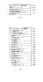
主制御装置110では、特別図柄の抽選、普通図柄の抽選、第1図柄表示装置37における表示の設定、第2図柄表示装置83における表示の設定、および、第3図柄表示装置81における表示の設定といったパチンコ機10の主要な処理を実行する。そして、RAM203には、これらの処理を制御するための各種カウンタが設けられている。ここで、図13を参照して、主制御装置110のRAM203内に設けられるカウンタ等について説明する。これらのカウンタ等は、特別図柄の抽選、普通図柄の抽選、第1図柄表示装置37における表示の設定、第2図柄表示装置83における表示の設定、および、第3図柄表示装置81における表示の設定などを行うために、主制御装置110のMPU201で使用される。
In the
特別図柄の抽選や、第1図柄表示装置37および第3図柄表示装置81の表示の設定には、特別図柄の抽選に使用する第1当たり乱数カウンタC1と、特別図柄の大当たり種別を選択するために使用する第1当たり種別カウンタC2と、特別図柄における外れの停止種別を選択するために使用する停止種別選択カウンタC3と、第1当たり乱数カウンタC1の初期値設定に使用する第1初期値乱数カウンタCINI1と、変動パターン選択に使用する変動種別カウンタCS1とが用いられる。また、普通図柄の抽選には、第2当たり乱数カウンタC4が用いられ、第2当たり乱数カウンタC4の初期値設定には第2初期値乱数カウンタCINI2が用いられる。これら各カウンタは、更新の都度、前回値に1が加算され、最大値に達した後0に戻るループカウンタとなっている。
To set the display of the special symbol lottery and the display of the first
各カウンタは、例えば、タイマ割込処理(図22参照)の実行間隔である2ミリ秒間隔で更新され、また、一部のカウンタは、メイン処理(図30参照)の中で不定期に更新されて、その更新値がRAM203の所定領域に設定されたカウンタ用バッファに適宜格納される。RAM203には、1つの実行エリアと4つの保留エリア(保留第1〜第4エリア)とからなる特別図柄保留球格納エリア203aが設けられており、これらの各エリアには、第1入球口64への入球タイミングに合わせて、第1当たり乱数カウンタC1、第1当たり種別カウンタC2及び停止種別選択カウンタC3の各値がそれぞれ格納される。また、RAM203には、1つの実行エリアと4つの保留エリア(保留第1〜第4エリア)とからなる普通図柄保留球格納エリア203bが設けられており、これらの各エリアには、球が左右何れかの普通入球口(スルーゲート)67を通過したタイミングに合わせて、第2当たり乱数カウンタC4の値が格納される。
Each counter is updated, for example, at intervals of 2 milliseconds, which is the execution interval of the timer interrupt process (see FIG. 22), and some counters are updated irregularly in the main process (see FIG. 30). Then, the updated value is appropriately stored in the counter buffer set in the predetermined area of the
各カウンタについて詳しく説明する。第1当たり乱数カウンタC1は、所定の範囲(例えば、0〜399)内で順に1ずつ加算され、最大値(例えば、0〜399の値を取り得るカウンタの場合は399)に達した後0に戻る構成となっている。特に、第1当たり乱数カウンタC1が1周した場合、その時点の第1初期値乱数カウンタCINI1の値が当該第1当たり乱数カウンタC1の初期値として読み込まれる。 Each counter will be described in detail. The first random number counter C1 is incremented by 1 in order within a predetermined range (for example, 0 to 399), reaches the maximum value (for example, 399 in the case of a counter that can take a value of 0 to 399), and then becomes 0. It is configured to return to. In particular, when the first random number counter C1 makes one round, the value of the first initial value random number counter CINI1 at that time is read as the initial value of the first random number counter C1.
また、第1初期値乱数カウンタCINI1は、第1当たり乱数カウンタC1と同一範囲で更新されるループカウンタとして構成される。即ち、例えば、第1当たり乱数カウンタC1が0〜399の値を取り得るループカウンタである場合には、第1初期値乱数カウンタCINI1もまた、0〜399の範囲のループカウンタである。この第1初期値乱数カウンタCINI1は、タイマ割込処理(図22参照)の実行毎に1回更新されると共に、メイン処理(図30参照)の残余時間内で繰り返し更新される。 Further, the first initial value random number counter CINI1 is configured as a loop counter updated in the same range as the first random number counter C1. That is, for example, when the first random number counter C1 is a loop counter that can take a value of 0 to 399, the first initial value random number counter CINI1 is also a loop counter in the range of 0 to 399. The first initial value random number counter CINI1 is updated once for each execution of the timer interrupt process (see FIG. 22), and is repeatedly updated within the remaining time of the main process (see FIG. 30).
第1当たり乱数カウンタC1の値は、例えば定期的に(本実施形態ではタイマ割込処理毎に1回)更新され、球が第1入球口64に入賞したタイミングでRAM203の特別図柄保留球格納エリア203aに格納される。そして、特別図柄の大当たりとなる乱数の値は、主制御装置110のROM202に格納される第1当たり乱数テーブル202a(図示せず)によって設定されており、第1当たり乱数カウンタC1の値が、第1当たり乱数テーブルによって設定された大当たりとなる乱数の値と一致する場合に、特別図柄の大当たりと判定する。また、この第1当たり乱数テーブル202aは、特別図柄の低確率時(特別図柄の低確率状態である期間)用と、その低確率時より特別図柄の大当たりとなる確率の高い高確率時(特別図柄の高確率状態である期間)用との2種類に分けられ、それぞれに含まれる大当たりとなる乱数の個数が異なって設定されている。このように、大当たりとなる乱数の個数を異ならせることにより、特別図柄の低確率時と特別図柄の高確率時とで、大当たりとなる確率が変更される。
The value of the first random number counter C1 is updated periodically (once for each timer interrupt process in this embodiment), and the special symbol holding ball of the
ここで、第1当たり乱数テーブル202aについて説明する。第1当たり乱数テーブル202aは、特別図柄の抽選において、各遊技状態で当たりと判定される乱数値(判定値)が設定されたテーブルである。具体的には、特別図柄の確変状態である場合には、特別図柄の抽選において、取得した第1当たり乱数カウンタC1の値が「0〜9」のいずれであるか判別されて、「0〜9」のいずれかであれば、大当たりであると判別される。第1当たり乱数カウンタC1の取り得る値が「0〜399」の400個ある中で、大当たりとなる判定値が「0〜9」の10個なので、特別図柄の確変中に特別図柄の大当たりとなる確率は、1/40(10/400)となる。また、特別図柄の低確率状態である場合には、取得した第1当たり乱数カウンタC1の値が「200」であるか判別されて、「200」であれば大当たりであると判別される。第1当たり乱数カウンタC1の取り得る値が「0〜399」の400個ある中で、大当たりとなる判定値が「200」の1個のみなので、特別図柄の低確率状態おいてに特別図柄の大当たりとなる確率は、1/400となる。 Here, the first random number table 202a will be described. The first hit random number table 202a is a table in which a random number value (determination value) determined to be a hit in each game state is set in a special symbol lottery. Specifically, in the case of the probability variation state of the special symbol, in the special symbol lottery, it is determined whether the value of the acquired first random number counter C1 is "0 to 9", and "0 to 9". If it is any of 9 ”, it is determined that it is a big hit. The first hit random number counter C1 has 400 possible values of "0 to 399", and the judgment value that becomes a big hit is 10 of "0 to 9". The probability of becoming 1/40 (10/400). Further, in the case of the low probability state of the special symbol, it is determined whether the value of the acquired first random number counter C1 is "200", and if it is "200", it is determined to be a big hit. Of the 400 possible values of the random number counter C1 per first, there is only one judgment value of "200" that is a big hit, so the special symbol is placed in the low probability state of the special symbol. The probability of winning a jackpot is 1/400.
なお、本実施形態では、低確率時用の第1当たり乱数テーブルに格納されている大当たりとなる乱数値と、高確率時用の第1当たり乱数テーブルに格納されている大当たりとなる乱数値とで、重複した値とならないように、それぞれの大当たりとなる乱数値を設定している。ここで、大当たりとなる乱数値としてパチンコ機10の状況にかかわらず常に用いられる値が存在すれば、その乱数値が外部より入力されて、不正に大当たりを引き当てられやすくなるおそれがある。これに対して、本実施形態のように、状況に応じて(即ち、パチンコ機10が特別図柄の高確率状態か、特別図柄の低確率状態かに応じて)、大当たりとなる乱数値を変えることで、特別図柄の大当たりとなる乱数値が予測され難くすることができるので、不正に対する抑制を図ることができる。
In the present embodiment, the random number value that is the jackpot stored in the first hit random number table for the low probability time and the random number value that is the jackpot stored in the first hit random number table for the high probability time. So, the random number values that are the big hits are set so that the values do not overlap. Here, if there is a value that is always used as a random value that becomes a big hit regardless of the situation of the
第1当たり種別カウンタC2は、特別図柄の大当たりとなった場合に、第1図柄表示装置37の表示態様を決定するものであり、所定の範囲(例えば、0〜99)内で順に1ずつ加算され、最大値(例えば、0〜99の値を取り得るカウンタの場合は99)に達した後0に戻る構成となっている。第1当たり種別カウンタC2の値は、例えば、定期的に(本実施形態ではタイマ割込処理毎に1回)更新され、球が第1入球口64に入賞したタイミングでRAM203の特別図柄保留球格納エリア203aに格納される。
The first hit type counter C2 determines the display mode of the first
ここで、特別図柄保留球格納エリア203aに格納された第1当たり乱数カウンタC1の値が、特別図柄の大当たりとなる乱数でなければ、即ち、特別図柄の外れとなる乱数であれば、第1図柄表示装置37に表示される停止図柄に対応した表示態様は、特別図柄の外れ時のものとなる。
Here, if the value of the first hit random number counter C1 stored in the special symbol holding
一方で、特別図柄保留球格納エリア203aに格納された第1当たり乱数カウンタC1の値が、特別図柄の大当たりとなる乱数であれば、第1図柄表示装置37に表示される停止図柄に対応した表示態様は、特別図柄の大当たり時のものとなる。この場合、その大当たり時の具体的な表示態様は、同じ特別図柄保留球格納エリア203aに格納されている第1当たり種別カウンタC2の値が示す表示態様となる。
On the other hand, if the value of the first hit random number counter C1 stored in the special symbol holding
また、本実施形態のパチンコ機10における第1当たり種別カウンタC2の値は、0〜99の範囲のループカウンタとして構成されている。そして、図11(b)を参照して上述したように、この第1当たり種別カウンタC2において、乱数値が「0〜49」であった場合の大当たり種別は「大当たりA」となる(図11(b)の202b1参照)。また、値が「50〜99」であった場合の大当たり種別は「大当たりB」となる(図11(c)の202b2参照)。このように、本実施形態のパチンコ機10は、第1当たり種別カウンタC2が示す乱数の値によって、2種類の当たり種別(大当たりA、大当たりB)が決定されるように構成されている。
Further, the value of the first type counter C2 in the
停止種別選択カウンタC3は、例えば0〜99の範囲内で順に1ずつ加算され、最大値(つまり99)に達した後0に戻る構成となっている。本実施形態では、停止種別選択カウンタC3によって、第3図柄表示装置81で表示される外れ時の停止種別が選択され、リーチが発生した後、最終停止図柄がリーチ図柄の前後に1つだけずれて停止する「前後外れリーチ」(例えば98,99)と、同じくリーチ発生した後、最終停止図柄がリーチ図柄の前後以外で停止する「前後外れ以外リーチ」(例えば90〜97の範囲)と、リーチ発生しない「完全外れ」(例えば0〜89の範囲)との3つの停止(演出)パターンが選択される。停止種別選択カウンタC3の値は、例えば定期的に(本実施形態ではタイマ割込処理毎に1回)更新され、球が第1入球口64に入賞したタイミングでRAM203の特別図柄保留球格納エリア203aに格納される。
The stop type selection counter C3 is configured to be incremented by 1 in order within the range of 0 to 99, and returns to 0 after reaching the maximum value (that is, 99). In the present embodiment, the stop type selection counter C3 selects the stop type at the time of disconnection displayed on the third
なお、停止種別選択カウンタC3の値(乱数値)から、特別図柄の停止種別を決定するための乱数値は、停止種別選択テーブル(図示せず)により設定されており、このテーブルは、主制御装置110のROM202内に設けられている。また、本実施形態ではこのテーブルを、特別図柄の高確率時用と、特別図柄の低確率時用とに分けており、テーブルに応じて、外れの停止種別ごとに設定される乱数値の範囲を変えている。これは、パチンコ機10が特別図柄の高確率状態であるか、特別図柄の低確率状態であるか等に応じて、停止種別の選択比率を変更するためである。
From the value (random value) of the stop type selection counter C3, the random number value for determining the stop type of the special symbol is set by the stop type selection table (not shown), and this table is the main control. It is provided in the
例えば、高確率状態では、大当たりが発生し易いため必要以上にリーチ演出が選択されないように、「完全外れ」の停止種別に対応した乱数値の範囲が0〜89と広い高確率時用のテーブルが選択され、「完全外れ」が選択され易くなる。このテーブルは、「前後外れリーチ」が98,99と狭くなると共に「前後外れ以外リーチ」も90〜97と狭くなり、「前後外れリーチ」や「前後外れ以外リーチ」が選択され難くなる。また、低確率状態であれば、第1入球口64への球の入球時間を確保するために「完全外れ」の停止種別に対応した乱数値の範囲が0〜79と狭い低確率時用のテーブルが選択され、「完全外れ」が選択され難くなる。
For example, in a high-probability state, a table for high-probability times where the range of random value corresponding to the stop type of "completely off" is wide, 0 to 89, so that the reach effect is not selected more than necessary because a big hit is likely to occur. Is selected, and "completely off" is easily selected. In this table, the "reach outside the front and rear" is narrowed to 98,99 and the "reach other than the front and rear" is also narrowed to 90 to 97, making it difficult to select "reach outside the front and back" or "reach other than the front and rear". Further, in the low probability state, the range of the random number value corresponding to the stop type of "completely off" is narrow as 0 to 79 in order to secure the ball entry time to the
この停止種別選択テーブルは、「前後外れ以外リーチ」の停止種別に対応した乱数値の範囲が80〜97と広くなり、「前後外れ以外リーチ」が選択され易くなっている。よって、低確率状態では、演出時間の長いリーチ表示を多く行うことできるので、第1入球口64への球の入球時間を確保でき、第3図柄表示装置81による変動表示が継続して行われ易くなる。なお、後者のテーブルにおいても、「前後外れリーチ」の停止種別に対応した乱数値の範囲は98,99に設定される。
In this stop type selection table, the range of random value corresponding to the stop type of "reach other than front and rear deviation" is widened to 80 to 97, and "reach other than front and rear deviation" is easily selected. Therefore, in the low probability state, it is possible to perform many reach displays with a long effect time, so that the ball entry time to the
変動種別カウンタCS1は、例えば0〜198の範囲内で順に1ずつ加算され、最大値(つまり198)に達した後0に戻る構成となっている。変動種別カウンタCS1によって、いわゆるノーマルリーチ、スーパーリーチ等の大まかな表示態様が決定される。表示態様の決定は、具体的には、図柄変動の変動時間の決定である。変動種別カウンタCS1により決定された変動時間に基づいて、音声ランプ制御装置113や表示制御装置114により第3図柄表示装置81で表示される第3図柄のリーチ種別や細かな図柄変動態様が決定される。変動種別カウンタCS1の値は、後述するメイン処理(図30参照)が1回実行される毎に1回更新され、当該メイン処理内の残余時間内でも繰り返し更新される。なお、変動種別カウンタCS1の値(乱数値)から、図柄変動の変動時間を一つ決定する乱数値を格納した変動パターン選択テーブル202d(図12参照)は、上述した通り、主制御装置110のROM202内に設けられている。
The variation type counter CS1 is configured to be incremented by 1 in order within the range of 0 to 198, and returns to 0 after reaching the maximum value (that is, 198). The variation type counter CS1 determines a rough display mode such as so-called normal reach and super reach. Specifically, the determination of the display mode is the determination of the fluctuation time of the symbol variation. Based on the fluctuation time determined by the variation type counter CS1, the reach type and the fine symbol variation mode of the third symbol displayed by the third
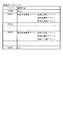
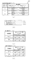
ここで、図12(a)〜(d)を参照して変動パターン選択テーブル202dの詳細について説明する。この変動パターン選択テーブル202dは、図12(a)に示すように、大当たり用変動パターンテーブル202d1(図12(b)参照)と、外れ用(通常)変動パターンテーブル202d2(図12(c)参照)と、外れ用(確変)変動パターンテーブル202d3(図12(d)参照)とが少なくとも設定されている。 Here, the details of the variation pattern selection table 202d will be described with reference to FIGS. 12 (a) to 12 (d). As shown in FIG. 12 (a), the fluctuation pattern selection table 202d includes a jackpot fluctuation pattern table 202d1 (see FIG. 12 (b)) and a deviation (normal) fluctuation pattern table 202d2 (see FIG. 12 (c)). ) And the deviation pattern table 202d3 (see FIG. 12 (d)) are set at least.
まず、図12(b)を参照して、大当たり用変動パターンテーブル202d1について説明する。図12(b)は、この大当たり用変動パターンテーブル202d1の内容を模式的に示した模式図である。大当たり用変動パターンテーブル202d1は、特別図柄の抽選結果が大当たりである場合に、選択される変動パターンの種別(変動時間)が規定されたデータテーブルである。大当たりの変動パターンとしては、ノーマルリーチ各種(30秒)、スーパーリーチ各種(60秒)、スペシャルリーチ(90秒)がそれぞれ規定されている。大当たり用変動パターンテーブル202d1には、変動種別カウンタCS1の値毎に、各変動パターンが対応付けられている。 First, the jackpot variation pattern table 202d1 will be described with reference to FIG. 12 (b). FIG. 12B is a schematic diagram schematically showing the contents of the jackpot variation pattern table 202d1. The jackpot variation pattern table 202d1 is a data table in which the type (variation time) of the variation pattern to be selected is defined when the lottery result of the special symbol is a jackpot. As the fluctuation pattern of the jackpot, various normal reach (30 seconds), various super reach (60 seconds), and special reach (90 seconds) are defined respectively. In the jackpot variation pattern table 202d1, each variation pattern is associated with each value of the variation type counter CS1.
具体的には、変動種別カウンタCS1の値の判定値として「0〜50」の範囲にはノーマルリーチ各種(30秒)の変動パターンが対応付けられ、「51〜179」の範囲にはスーパーリーチ各種(60秒)の変動パターンが対応付けられ、「180〜198」の範囲にはスペシャルリーチ各種(90秒)の変動パターンが対応付けられている。主制御装置110のMPU201は、特別図柄の抽選結果が大当たりとなる場合の変動パターンを選択する場合に、取得している変動種別カウンタCS1の値に対応する判定値が設定されている変動パターンを大当たり用変動パターンテーブル202d1より選択する。
Specifically, as a judgment value of the value of the fluctuation type counter CS1, various fluctuation patterns of normal reach (30 seconds) are associated with the range of "0 to 50", and various super reach are associated with the range of "51 to 179". Fluctuation patterns of (60 seconds) are associated, and variation patterns of various special reach (90 seconds) are associated with the range of "180 to 198". The
図12(c)は、外れ用(通常)変動パターンテーブル202d2の内容を模式的に示した模式図である。外れ用(通常)変動パターンテーブル202d2は、特別図柄の低確率状態において、特別図柄の抽選結果が外れであった場合に選択される変動パターンの種別(変動時間)が規定されたデータテーブルである。特別図柄の抽選結果が外れである場合には、上述したように、図示しない停止種別選択テーブルより停止種別が完全外れ(非リーチ)であるか、リーチ外れ(リーチ共通)であるかが停止種別選択カウンタC3の値によって決定される。具体的には、例えば、特別図柄の低確率状態において停止種別選択カウンタC3の値が「0〜79」の範囲にあれば完全外れを設定し、「80〜99」の範囲にあれば外れリーチ(前後外れリーチ、前後外れ以外リーチ)を設定する。 FIG. 12 (c) is a schematic diagram schematically showing the contents of the deviation pattern table 202d2. The out-of-order (normal) variation pattern table 202d2 is a data table in which the type (variation time) of the variation pattern selected when the lottery result of the special symbol is out of order in the low probability state of the special symbol is defined. .. If the lottery result of the special symbol is out of order, as described above, the stop type is completely out of reach (non-reach) or out of reach (common to reach) from the stop type selection table (not shown). It is determined by the value of the selection counter C3. Specifically, for example, in the low probability state of a special symbol, if the value of the stop type selection counter C3 is in the range of "0 to 79", a complete deviation is set, and if it is in the range of "80 to 99", the deviation reach is set. Set (reach out of front and back, reach other than out of front and back).
ここで、変動パターン種別が、完全外れである場合には、変動時間が比較的短い短外れ(7秒)と、変動時間が比較的長い長外れ(10秒)のいずれかが設定される。短外れ(7秒)に対しては、「0〜98」が、長外れ(10秒)に対しては、「99〜198」が変動種別カウンタCS1の判定値として設定されている。 Here, when the fluctuation pattern type is a complete deviation, either a short deviation (7 seconds) in which the fluctuation time is relatively short or a long deviation (10 seconds) in which the fluctuation time is relatively long is set. For a short deviation (7 seconds), "0 to 98" is set as a determination value, and for a long deviation (10 seconds), "99 to 198" is set as a determination value of the variation type counter CS1.
また、外れリーチに対しては、変動種別カウンタCS1の判定値が「0〜149」の範囲には外れのノーマルリーチ各種(30秒)が、「150〜197」の範囲には外れのスーパーリーチ各種(60秒)が、「198」には外れのスペシャルリーチ各種(90秒)がそれぞれ設定されている。 In addition, for the out-of-reach, various out-of-normal reach (30 seconds) are in the range where the judgment value of the fluctuation type counter CS1 is "0 to 149", and various out-of-range super reach are in the range of "150 to 197". (60 seconds), but "198" is set with various special reach (90 seconds).
このように、主制御装置110のMPU201は、通常遊技状態時に特別図柄の抽選結果が外れである場合には、停止種別が決定され、外れ用(通常)変動パターンテーブル202d2より取得している変動種別カウンタCS1の値に基づいて、外れ用(通常)変動パターンテーブル202d2より変動パターンを選択する。
As described above, in the
図12(d)は、外れ用(確変)変動パターンテーブル202d3の内容を模式的に示した模式図である。この外れ用(確変)変動パターンテーブル202d3は、特別図柄の確変状態において、特別図柄の抽選が外れとなった場合に選択される変動パターンの種別(変動時間)が規定されたデータテーブルである。この外れ用(確変)変動パターンテーブル202d3では、設定されている変動種別カウンタCS1の値が、上述した外れ用(通常)変動パターンテーブル202d2とは異なっている。 FIG. 12D is a schematic diagram schematically showing the contents of the deviation pattern table 202d3 for deviation (probability variation). The deviation pattern table 202d3 is a data table in which the type (variation time) of the variation pattern selected when the lottery of the special symbol is out of order in the probability variation state of the special symbol is defined. In this deviation (probability variation) variation pattern table 202d3, the value of the variation type counter CS1 set is different from the deviation (normal) variation pattern table 202d2 described above.
なお、上述したように、遊技状態が確変遊技状態である場合には、図示しない停止種別選択テーブルにより停止種別選択カウンタC3の値が「0〜89」の範囲にあれば、完全外れが決定され、「90〜99」の範囲にあれば外れリーチ(前後外れリーチ、前後外れ以外リーチ)が決定される。 As described above, when the gaming state is the probabilistic gaming state, if the value of the stop type selection counter C3 is in the range of "0 to 89" by the stop type selection table (not shown), complete deviation is determined. , If it is in the range of "90 to 99", the out-of-bounds reach (front-back out-of-front reach, non-front-back out-of-reach reach) is determined.
このように、通常遊技状態よりも確変遊技状態である場合には、外れである場合にリーチとなる確率が低く設定されている。よって、確変時に外れの変動時間が長くなってしまい、大当たりとなるまでの期間が長くなってしまうことを抑制できる。よって、大当たりし易い確変遊技状態時に遊技が間延びしてしまい、遊技者が退屈に感じる不具合を抑制できる。 As described above, in the case of the probabilistic gaming state than in the normal gaming state, the probability of reaching is set lower when the game is out of the game. Therefore, it is possible to suppress that the fluctuation time of the deviation becomes long at the time of the probability change and the period until the big hit becomes long. Therefore, it is possible to suppress a problem that the player feels bored because the game is delayed in the probabilistic game state where a big hit is likely to occur.
図13に戻って説明を続ける。第2当たり乱数カウンタC4は、例えば0〜239の範囲内で順に1ずつ加算され、最大値(つまり239)に達した後0に戻るループカウンタとして構成されている。また、第2当たり乱数カウンタC4が1周した場合、その時点の第2初期値乱数カウンタCINI2の値が当該第2当たり乱数カウンタC4の初期値として読み込まれる。第2当たり乱数カウンタC4の値は、本実施形態ではタイマ割込処理毎に、例えば定期的に更新され、球が左右何れかの普通入球口(スルーゲート)67を通過したことが検知された時に取得され、RAM203の普通図柄保留球格納エリア203bに格納される。
The explanation will be continued by returning to FIG. The second random number counter C4 is configured as a loop counter in which, for example, 1 is sequentially added in the range of 0 to 239, the maximum value (that is, 239) is reached, and then the value returns to 0. Further, when the second random number counter C4 makes one round, the value of the second initial value random number counter CINI2 at that time is read as the initial value of the second random number counter C4. In the present embodiment, the value of the second random number counter C4 is updated periodically, for example, every time the timer is interrupted, and it is detected that the ball has passed through the normal entry port (through gate) 67 on either the left or right side. At that time, it is acquired and stored in the normal symbol holding
そして、普通図柄の当たりとなる乱数の値は、主制御装置のROM202に格納される第2当たり乱数テーブル202c(図11(c)参照)によって設定されており、第2当たり乱数カウンタC4の値が、第2当たり乱数テーブルによって設定された当たりとなる乱数の値と一致する場合に、普通図柄の当たりと判定する。また、この第2当たり乱数テーブルは、普通図柄の低確率時(普通図柄の通常状態である期間)用と、その低確率時より普通図柄の当たりとなる確率の高い高確率時(普通図柄の時短状態である期間)用との2種類に分けられ、それぞれに含まれる大当たりとなる乱数の個数が異なって設定されている。このように、当たりとなる乱数の個数を異ならせることにより、普通図柄の低確率時と普通図柄の高確率時とで、当たりとなる確率が変更される。
The value of the random number that is a hit of the normal symbol is set by the second hit random number table 202c (see FIG. 11C) stored in the
図11(c)を参照して上述した通り、普通図柄の低確率時に、普通図柄の当たりとなる乱数値は24個あり、その範囲は「5〜28」となっている(図11(c)の202c1参照)。これら乱数値は、低確率時用の第2当たり乱数テーブルに格納されている。このように普通図柄の低確率時には、乱数値の総数が240ある中で、大当たりとなる乱数値の総数が24なので、特別図柄の大当たりとなる確率は、「1/10」となる。 As described above with reference to FIG. 11 (c), when the probability of the normal symbol is low, there are 24 random values that can be hit by the normal symbol, and the range is "5-28" (FIG. 11 (c). ) 202c1). These random number values are stored in the second random number table for low probability. As described above, when the probability of a normal symbol is low, the total number of random numbers that become a jackpot is 24 while the total number of random numbers is 240, so the probability of a jackpot of a special symbol is "1/10".
パチンコ機10が普通図柄の低確率時である場合に、球が普通入球口67を通過すると、第2当たり乱数カウンタC4の値が取得されると共に、第2図柄表示装置83において普通図柄の変動表示が30秒間実行される。そして、取得された第2当たり乱数カウンタC4の値が「5〜28」の範囲であれば当選と判定されて、第2図柄表示装置83における変動表示が終了した後に、停止図柄(第2図柄)として「○」の図柄が点灯表示されると共に、第1入球口64が「0.2秒間×1回」だけ開放される。なお、本実施形態では、パチンコ機10が普通図柄の低確率時である場合に、普通図柄の当たりとなったら第1入球口64が「0.2秒間×1回」だけ開放されるが、開放時間や回数は任意に設定すれば良い。例えば、「0.5秒間×2回」に設定しても良い。
When the ball passes through the
一方で、普通図柄の高確率時に、普通図柄の大当たりとなる乱数値は200個あり、その範囲は「5〜204」となっている(図11(c)の202c2参照)。これらの乱数値は、高確率時用の第2当たり乱数テーブルに格納されている。このように特別図柄の低確率時には、乱数値の総数が240ある中で、大当たりとなる乱数値の総数が200なので、特別図柄の大当たりとなる確率は、「1/1.2」となる。 On the other hand, when there is a high probability of a normal symbol, there are 200 random values that are big hits of the normal symbol, and the range is "5-204" (see 202c2 in FIG. 11 (c)). These random number values are stored in the second random number table for high probability. As described above, when the probability of the special symbol is low, the total number of random random values is 200 while the total number of random numbers is 240, so the probability of the special symbol being a jackpot is "1 / 1.2".
パチンコ機10が普通図柄の高確率時である場合に、球が普通入球口67を通過すると、第2当たり乱数カウンタC4の値が取得されると共に、第2図柄表示装置83において普通図柄の変動表示が3秒間実行される。そして、取得された第2当たり乱数カウンタC4の値が「5〜204」の範囲であれば当選と判定されて、第2図柄表示装置83における変動表示が終了した後に、停止図柄(第2図柄)として「○」の図柄が点灯表示されると共に、第1入球口64が「1秒間×2回」開放される。このように、普通図柄の高確率時には、普通図柄の低確率時と比較して、変動表示の時間が「30秒→3秒」と非常に短くなり、更に、第1入球口64の開放期間が「0.2秒×1回→1秒間×2回」と非常に長くなるので、第1入球口64へ球が入球し易い状態となる。なお、本実施形態では、パチンコ機10が普通図柄の高確率時である場合に、普通図柄の当たりとなったら第1入球口64が「1秒間×2回」だけ開放されるが、開放時間や回数は任意に設定すれば良い。例えば、「3秒間×3回」開放しても良い。
When the ball passes through the
第2初期値乱数カウンタCINI2は、第2当たり乱数カウンタC4と同一範囲で更新されるループカウンタとして構成され(値=0〜239)、タイマ割込処理(図22参照)毎に1回更新されると共に、メイン処理(図30参照)の残余時間内で繰り返し更新される。 The second initial value random number counter CINI2 is configured as a loop counter that is updated in the same range as the second random number counter C4 (value = 0 to 239), and is updated once for each timer interruption process (see FIG. 22). At the same time, it is repeatedly updated within the remaining time of the main process (see FIG. 30).
このように、RAM203には種々のカウンタ等が設けられており、主制御装置110では、このカウンタ等の値に応じて大当たり抽選や第1図柄表示装置37および第3図柄表示装置81における表示の設定、第2図柄表示装置83における表示結果の抽選といったパチンコ機10の主要な処理を実行することができる。
As described above, the
図10に戻り、説明を続ける。RAM203は、図13に図示した各種カウンタのほか、MPU201の内部レジスタの内容やMPU201により実行される制御プログラムの戻り先番地などが記憶されるスタックエリアと、各種のフラグおよびカウンタ、I/O等の値が記憶される作業エリア(作業領域)とを有している。
Returning to FIG. 10, the description will be continued. In addition to the various counters shown in FIG. 13, the
なお、RAM203は、パチンコ機10の電源の遮断後においても電源装置115からバックアップ電圧が供給されてデータを保持(バックアップ)できる構成となっており、RAM203に記憶されるデータは、すべてバックアップされる。
The
停電などの発生により電源が遮断されると、その電源遮断時(停電発生時を含む。以下同様)のスタックポインタや、各レジスタの値がRAM203に記憶される。一方、電源投入時(停電解消による電源投入を含む。以下同様)には、RAM203に記憶される情報に基づいて、パチンコ機10の状態が電源遮断前の状態に復帰される。RAM203への書き込みはメイン処理(図30参照)によって電源遮断時に実行され、RAM203に書き込まれた各値の復帰は電源投入時の立ち上げ処理(図29参照)において実行される。なお、MPU201のNMI端子(ノンマスカブル割込端子)には、停電等の発生による電源遮断時に、停電監視回路252からの停電信号SG1が入力されるように構成されており、その停電信号SG1がMPU201へ入力されると、停電時処理としてのNMI割込処理(図28参照)が即座に実行される。
When the power is cut off due to the occurrence of a power failure or the like, the stack pointer at the time of the power failure (including the time when a power failure occurs; the same applies hereinafter) and the value of each register are stored in the
また、RAM203は、図10に示すように、特別図柄保留球格納エリア203aと、普通図柄保留球格納エリア203bと、特別図柄保留球数カウンタ203cと、普通図柄保留球数カウンタ203dと、確変フラグ203eと、時短中カウンタ203fとを少なくとも有している。
Further, as shown in FIG. 10, the
特別図柄保留球格納エリア203aは、1つの実行エリアと、4つの保留エリア(保留第1エリア〜保留第4エリア)とを有しており、これらの各エリアには、第1当たり乱数カウンタC1、第1当たり種別カウンタC2、及び停止種別選択カウンタC3の各値がそれぞれ格納される。
The special symbol holding
より具体的には、球が第1入球口64へ入賞(始動入賞)したタイミングで、各カウンタC1〜C3の各値が取得され、その取得されたデータが、4つの保留エリア(保留第1エリア〜保留第4エリア)の空いているエリアの中で、エリア番号(第1〜第4)の小さいエリアから順番に記憶される。つまり、エリア番号の小さいエリアほど、時間的に古い入賞に対応するデータが記憶され、保留第1エリアには、時間的に最も古い入賞に対応するデータが記憶される。なお、4つの保留エリアの全てにデータが記憶されている場合には、新たに何も記憶されない。 More specifically, at the timing when the ball wins the first ball opening 64 (starting winning), each value of each counter C1 to C3 is acquired, and the acquired data is stored in four holding areas (holding first). Among the vacant areas (1st area to 4th area on hold), the areas with the smallest area numbers (1st to 4th) are stored in order. That is, the smaller the area number, the data corresponding to the oldest prize in time is stored, and the data corresponding to the oldest prize in time is stored in the reserved first area. If data is stored in all four holding areas, nothing is newly stored.
その後、主制御装置110において、特別図柄の抽選が行われる場合には、特別図柄保留球格納エリア203aの保留第1エリアに記憶されている各カウンタC1〜C3の各値が、実行エリアへシフトされ(移動させられ)、その実行エリアに記憶された各カウンタC1〜C3の各値に基づいて、特別図柄の抽選などの判定が行われる。
After that, when the special symbol lottery is performed in the
なお、保留第1エリアから実行エリアへデータをシフトすると、保留第1エリアが空き状態となる。そこで、他の保留エリア(保留第2エリア〜保留第4エリア)に記憶されている入賞のデータを、エリア番号の1小さい保留エリア(保留第1エリア〜保留第3エリア)に詰めるシフト処理が行われる。本実施形態では、特別図柄保留球格納エリア203aにおいて、入賞のデータが記憶されている保留エリア(第2保留エリア〜第4保留エリア)についてのみデータのシフトが行われる。
When the data is shifted from the hold 1st area to the execution area, the hold 1st area becomes empty. Therefore, a shift process is performed in which the winning data stored in the other holding areas (holding 2nd area to holding 4th area) is packed into the holding area (holding 1st area to holding 3rd area) having a smaller area number. Will be done. In the present embodiment, in the special symbol holding
本パチンコ機10では、球が第1入球口64へ入賞(始動入賞)し、その始動入賞に応じて各カウンタC1〜C3の各値が取得されると直ちに、本来の特別図柄の大当たり抽選とは別に、その取得された各カウンタC1〜C3の各値から、本来の抽選が行われた場合に得られる各種情報が予測(推定)される。このように、本来の特別図柄の抽選が行われる前に、始動入賞に対応するデータ(各カウンタC1〜C3の各値)に基づいて、本来の抽選が行われた場合に得られる各種情報を予測することを、以後、特別図柄の抽選結果を先読みすると記載する。なお、各種情報としては、当否、停止種別、変動パターンなどが該当する。
In this
そして、先読みが終了すると、先読みにより得られた各種情報(当否、停止種別、変動パターン)を含む入賞情報コマンドが音声ランプ制御装置113へ送信される。入賞情報コマンドが音声ランプ制御装置113によって受信されると、音声ランプ制御装置113は、入賞情報コマンドから、当否、停止種別、および変動パターンを抽出し、それらを入賞情報としてRAM223の入賞情報格納エリア223aに格納する。
Then, when the look-ahead is completed, a winning information command including various information (whether or not, stop type, fluctuation pattern) obtained by the look-ahead is transmitted to the voice
普通図柄保留球格納エリア203bは、特別図柄保留球格納エリア203aと同様に、1つの実行エリアと、4つの保留エリア(保留第1エリア〜保留第4エリア)とを有している。これらの各エリアには、第2当たり乱数カウンタC4が格納される。
The normal symbol holding
より具体的には、球が左右何れかの普通入球口67を通過したタイミングで、カウンタC4の値が取得され、その取得されたデータが、4つの保留エリア(保留第1エリア〜保留第4エリア)の空いているエリアの中で、エリア番号(第1〜第4)の小さいエリアから順番に記憶される。つまり、特別図柄保留球格納エリア203aと同様に、入賞した順序が保持されつつ、入賞に対応するデータが格納される。なお、4つの保留エリアの全てにデータが記憶されている場合には、新たに何も記憶されない。
More specifically, the value of the counter C4 is acquired at the timing when the ball passes through either the left or right
その後、主制御装置110において、普通図柄の当たりの抽選が行われる場合には、普通図柄保留球格納エリア203bの保留第1エリアに記憶されているカウンタC4の値が、実行エリアへシフトされ(移動させられ)、その実行エリアに記憶されたカウンタC4の値に基づいて、普通図柄の当たりの抽選などの判定が行われる。
After that, when the lottery for winning the normal symbol is performed in the
なお、保留第1エリアから実行エリアへデータをシフトすると、保留第1エリアが空き状態となるので、特別図柄保留球格納エリア203aの場合と同様に、他の保留エリアに記憶されている入賞のデータを、エリア番号の1小さい保留エリアに詰めるシフト処理が行われる。また、データのシフトも、入賞のデータが記憶されている保留エリアについてのみ行われる。
When the data is shifted from the hold 1st area to the execution area, the hold 1st area becomes empty. Therefore, as in the case of the special symbol hold
特別図柄保留球数カウンタ203cは、第1入球口64への入球(始動入賞)に基づいて第1図柄表示装置37で行われる特別図柄(第1図柄)の変動表示(第3図柄表示装置81で行われる変動表示)の保留球数(待機回数)を最大4回まで計数するカウンタである。この特別図柄保留球数カウンタ203cは、初期値がゼロに設定されており、第1入球口64へ球が入球して変動表示の保留球数が増加する毎に、最大値4まで1加算される(図25のS404参照)。一方、特別図柄保留球数カウンタ203cは、新たに特別図柄の変動表示が実行される毎に、1減算される(図23のS205参照)。
The special symbol reserved
この特別図柄保留球数カウンタ203cの値(特別図柄における変動表示の保留回数N)は、保留球数コマンドによって音声ランプ制御装置113に通知される(図23のS206、図25のS405参照)。保留球数コマンドは、特別図柄保留球数カウンタ203cの値が変更される度に、主制御装置110から音声ランプ制御装置113に対して送信されるコマンドである。
The value of the special symbol reserved
音声ランプ制御装置113は、特別図柄保留球数カウンタ203cの値が変更される度に、主制御装置110より送信される保留球数コマンドによって、主制御装置110に保留された変動表示の保留球数そのものの値を取得することができる。これにより、音声ランプ制御装置113の特別図柄保留球数カウンタ223bによって管理される変動表示の保留球数が、ノイズ等の影響によって、主制御装置110に保留された実際の変動表示の保留球数からずれてしまった場合であっても、次に受信する保留球数コマンドによって、そのずれを修正することができる。
The voice
なお、音声ランプ制御装置113は、保留球数コマンドに基づいて保留球数を管理し、保留球数が変化する度に表示制御装置114に対して、保留球数を通知するための表示用保留球数コマンドを送信する。表示制御装置114は、この表示用保留球数コマンドによって通知された保留球数を基に、第3図柄表示装置81の小領域Ds1に保留球数図柄を表示する。
The voice
普通図柄保留球数カウンタ203dは、普通入球口67における球の通過に基づいて第2図柄表示装置83で行われる普通図柄(第2図柄)の変動表示の保留球数(待機回数)を最大4回まで計数するカウンタである。この普通図柄保留球数カウンタ203dは、初期値がゼロに設定されており、球が普通入球口67を通過して変動表示の保留球数が増加する毎に、最大値4まで1加算される(図27のS604参照)。一方、普通図柄保留球数カウンタ203dは、新たに普通図柄(第2図柄)の変動表示が実行される毎に、1減算される(図26のS505参照)。
The normal symbol reserved
球が左右何れかの普通入球口67を通過した場合に、この普通図柄保留球数カウンタ203dの値(普通図柄における変動表示の保留回数M)が4未満であれば、第2当たり乱数カウンタC4の値が取得され、その取得されたデータが、普通図柄保留球格納エリア203bに記憶される(図27のS605)。一方、球が左右何れかの普通入球口67を通過した場合に、この普通図柄保留球数カウンタ203dの値が4であれば、普通図柄保留球格納エリア203bには新たに何も記憶されない(図27のS603:No)。
If the value of the normal symbol hold
確変フラグ203eは、パチンコ機10が特別図柄の確変状態(特別図柄の高確率状態)であるか否かを示すフラグであり、確変フラグ203eの値が1以上であれば、パチンコ機10が特別図柄の確変状態であることを示し、確変フラグ203eの値が0であれば、パチンコ機10が特別図柄の通常状態(特別図柄の低確率状態)であることを示す。この確変フラグ203eは、初期状態がオフに設定されており、特別図柄の大当たりAの終了時にオンに設定される(図31のS1014参照)。一方、特別図柄の抽選において大当たりとなった場合には、その大当たりの開始を設定する際にオフに設定される(図23のS213参照)。
The
MPU201によって特別図柄変動開始処理(図24参照)が実行されると、特別図柄の抽選が行われる。特別図柄変動開始処理では、確変フラグ203eが参照され、その状態がオンであれば、高確率時用の第1当たり乱数テーブルに基づいて、特別図柄の抽選が行われる一方、確変フラグ203eの状態がオフであれば、低確率時用の第1当たり乱数テーブルに基づいて、特別図柄の抽選が行われる(図24のS303,S304参照)。
When the special symbol change start process (see FIG. 24) is executed by the
時短中カウンタ203fは、パチンコ機10が普通図柄の時短状態であるか否かを示すカウンタであり、時短中カウンタ203fの値が1以上であれば、パチンコ機10が普通図柄の時短状態であることを示し、時短中カウンタ203fの値が0であれば、パチンコ機10が普通図柄の通常状態であることを示す。この時短中カウンタ203fは、初期値がゼロに設定されており、主制御装置110において特別図柄の抽選が行われ、大当たりBとなる度に、その大当たりBの終了時に値が100にセットされる(図31のS1013参照)。また、大当たり種別に関わらず、特別図柄の抽選により大当たりとなった場合は、その大当たりの開始を設定する中で値が0に設定される。
The time saving
普通図柄の当たりの抽選が行われる場合には、時短中カウンタ203fの値、および確変フラグ203eの状態が参照され、時短中カウンタ203fの値が1以上であるか、確変フラグ203eの状態がオンであれば、普通図柄の時短中と判別される。この場合、高確率時用の第2当たり乱数テーブルに基づいて、普通図柄の抽選が行われる(図26のS509参照)。一方、時短中カウンタ203fの値が0であり、且つ、確変フラグ203eの状態がオフであれば、普通図柄の通常状態と判別されて、低確率時用の第2当たり乱数テーブルに基づいて、普通図柄の抽選が行われる(図26のS510参照)。
When a lottery for winning a normal symbol is performed, the value of the time-saving / medium-
主制御装置110のMPU201には、アドレスバス及びデータバスで構成されるバスライン204を介して入出力ポート205が接続されている。入出力ポート205には、払出制御装置111、音声ランプ制御装置113、第1図柄表示装置37、第2図柄表示装置83、第2図柄保留ランプ84、特定入賞口65aの開閉板の下辺を軸として前方側に開閉駆動するための大開放口ソレノイドや電動役物64aを駆動するためのソレノイドなどからなるソレノイド209が接続され、MPU201は、入出力ポート205を介してこれらに対し各種コマンドや制御信号を送信する。
The input /
また、入出力ポート205には、図示しないスイッチ群やセンサ群などからなる各種スイッチ208や、電源装置115に設けられた後述のRAM消去スイッチ回路253が接続され、MPU201は各種スイッチ208から出力される信号や、RAM消去スイッチ回路253より出力されるRAM消去信号SG2に基づいて各種処理を実行する。
Further,
払出制御装置111は、払出モータ216を駆動させて賞球や貸出球の払出制御を行うものである。演算装置であるMPU211は、そのMPU211により実行される制御プログラムや固定値データ等を記憶したROM212と、ワークメモリ等として使用されるRAM213とを有している。
The
払出制御装置111のRAM213は、主制御装置110のRAM203と同様に、MPU211の内部レジスタの内容やMPU211により実行される制御プログラムの戻り先番地などが記憶されるスタックエリアと、各種のフラグおよびカウンタ、I/O等の値が記憶される作業エリア(作業領域)とを有している。RAM213は、パチンコ機10の電源の遮断後においても電源装置115からバックアップ電圧が供給されてデータを保持(バックアップ)できる構成となっており、RAM213に記憶されるデータは、すべてバックアップされる。なお、主制御装置110のMPU201と同様、MPU211のNMI端子にも、停電等の発生による電源遮断時に停電監視回路252から停電信号SG1が入力されるように構成されており、その停電信号SG1がMPU211へ入力されると、停電時処理としてのNMI割込処理が即座に実行される。
The
払出制御装置111のMPU211には、アドレスバス及びデータバスで構成されるバスライン214を介して入出力ポート215が接続されている。入出力ポート215には、主制御装置110や払出モータ216、発射制御装置112などがそれぞれ接続されている。また、図示はしないが、払出制御装置111には、払い出された賞球を検出するための賞球検出スイッチが接続されている。なお、該賞球検出スイッチは、払出制御装置111に接続されるが、主制御装置110には接続されていない。
An input /
発射制御装置112は、主制御装置110により球の発射の指示がなされた場合に、操作ハンドル51の回転操作量に応じた球の打ち出し強さとなるよう球発射ユニット112aを制御するものである。球発射ユニット112aは、図示しない発射ソレノイドおよび電磁石を備えており、その発射ソレノイドおよび電磁石は、所定条件が整っている場合に駆動が許可される。具体的には、遊技者が操作ハンドル51に触れていることをタッチセンサ51aにより検出し、球の発射を停止させるための打ち止めスイッチ51bがオフ(操作されていないこと)を条件に、操作ハンドル51の回動量に対応して発射ソレノイドが励磁され、操作ハンドル51の操作量に応じた強さで球が発射される。
The
音声ランプ制御装置113は、音声出力装置(図示しないスピーカなど)226における音声の出力、ランプ表示装置(電飾部29〜33、表示ランプ34など)227における点灯および消灯の出力、変動演出(変動表示)や連続予告演出といった表示制御装置114で行われる第3図柄表示装置81の表示態様の設定などを制御するものである。演算装置であるMPU221は、そのMPU221により実行される制御プログラムや固定値データ等を記憶したROM222と、ワークメモリ等として使用されるRAM223とを有している。
The audio
音声ランプ制御装置113のMPU221には、アドレスバス及びデータバスで構成されるバスライン224を介して入出力ポート225が接続されている。入出力ポート225には、主制御装置110、表示制御装置114、音声出力装置226、ランプ表示装置227、枠ボタン22などがそれぞれ接続されている。
An input /
音声ランプ制御装置113は、枠ボタン22からの入力を監視し、遊技者によって枠ボタン22が操作された場合は、第3図柄表示装置81で表示されるステージを変更したり、スーパーリーチ時の演出内容を変更したりするように、音声出力装置226、ランプ表示装置227を制御し、また、表示制御装置114へ指示する。ステージが変更される場合は、変更後のステージに応じた背面画像を第3図柄表示装置81に表示させるべく、変更後のステージに関する情報を含めた背面画像変更コマンドを表示制御装置114へ送信する。ここで、背面画像とは、第3図柄表示装置81に表示させる主要な画像である第3図柄の背面側に表示される画像のことである。
The voice
音声ランプ制御装置113は、主制御装置110からのコマンドや、音声ランプ制御装置113に接続された各種装置等の状況に応じてエラーを判定し、そのエラーの種別を含めてエラーコマンドを表示制御装置114へ送信する。表示制御装置114では、受信したエラーコマンドによって示されるエラー種別(例えば、振動エラー)に応じたエラーメッセージ画像を第3図柄表示装置81に遅滞無く表示させる制御が行われる。
The voice
ここで、図14、及び図15を参照して、音声ランプ制御装置113のMPU221が有するROM222、及びRAM223の詳細について説明する。まず、図14(a)は、ROM222の構成を示したブロック図である。図14(a)に示した通り、ROM222には、変動パターンテーブル222aと、変身演出選択テーブル222bと、発展演出態様選択テーブル222cとが少なくとも設けられている。
Here, the details of the
変動パターンテーブル222aは、主制御装置110において変動パターン選択テーブル202dを参照して選択された変動演出の大まかな表示態様(変動時間)に基づき、変動演出の詳細な表示態様を特定するために用いられる。より具体的には、主制御装置110により選択された表示態様を通知するための変動パターンコマンドを受信した場合に、変動パターンテーブル222aに規定されている変動パターンの中から1の変動パターン(変動演出の詳細な表示態様)を抽出(特定)する(図42のS5003参照)。この変動パターンテーブル222aに規定された変動パターンのうち、少なくとも変動時間が60秒のスーパーリーチに対応する変動パターンには、上述した連続変身演出(図5〜7参照)を実行するか否かを示す情報も含まれている。
The variation pattern table 222a is used to specify a detailed display mode of the variation effect based on a rough display mode (variation time) of the variation effect selected by referring to the variation pattern selection table 202d in the
変身演出選択テーブル222bは、変動パターンテーブル222aから、連続変身演出を伴う変動パターンが選択された場合に、当該連続変身演出の演出態様を決定するために参照されるデータテーブルである。この変身演出選択テーブル222bの詳細について、図15(a)を参照して説明する。 The transformation effect selection table 222b is a data table referred to for determining the effect mode of the continuous transformation effect when the variation pattern accompanied by the continuous transformation effect is selected from the variation pattern table 222a. The details of the transformation effect selection table 222b will be described with reference to FIG. 15 (a).
図15(a)は、変身演出選択テーブル222bの規定内容を示した図である。図15(a)に示した通り、この変身演出選択テーブル222bは、変動パターンの種別(当否)、およびRAM223に設けられた演出カウンタ223nの値毎に、連続変身演出の演出態様が規定されている。図15(a)に示した通り、連続変身演出の演出態様には、連続変身演出A〜Eの5種類が設定されている。
FIG. 15A is a diagram showing the specified contents of the transformation effect selection table 222b. As shown in FIG. 15A, in the transformation effect selection table 222b, the effect mode of the continuous transformation effect is defined for each type (whether or not) of the fluctuation pattern and the value of the
連続変身演出Aは、変身(成功報知態様)の最大(上限)回数が1回の連続変身演出であり、変身が可能な残変動時間の下限値は設定されていない。このため、連続変身演出Aが実行されると、遊技者が操作有効期間中に枠ボタン22を押下したか否かとは無関係に、成功報知態様が1回表示された後で、失敗報知態様が表示される。なお、図15(a)に示した通り、連続変身演出Aは、当たりスーパーリーチの場合で、且つ、演出カウンタ223nの値が「0」であった場合にのみ、選択される可能性がある。即ち、最大の変身回数が1回であれば、当該連続変身演出Aが設定された変動表示で大当たりとなることが確定する。上述した通り、連続変身演出では、基本的に変身回数(成功報知態様の表示回数)が多くなるほどに大当たりの期待度が高くなるが、連続変身演出Aの場合(最大回数が1回の場合)のみ、例外的に大当たりが確定する構成としている。これにより、意外性のある演出を提供することができる。
The continuous transformation effect A is a continuous transformation effect in which the maximum (upper limit) number of transformations (success notification mode) is one, and the lower limit of the residual fluctuation time during which transformation is possible is not set. Therefore, when the continuous transformation effect A is executed, the failure notification mode is displayed once after the success notification mode is displayed, regardless of whether or not the player presses the
連続変身演出Bは、変身(成功報知態様)の最大(上限)回数が2回の連続変身演出であり、当たりスーパーリーチでは、演出カウンタ223nの値が「1〜19」の範囲だった場合に選択される。一方、外れスーパーリーチの場合には、演出カウンタ223nの値が「0〜44」の範囲だった場合に選択される。演出カウンタ223nは、「0〜99」の範囲で更新されるループカウンタであるので、連続変身演出Bは、連続変身演出が決定された当たりスーパーリーチの場合の19%(19/100)の割合で決定される一方、連続変身演出が決定された外れスーパーリーチの場合の45%(45/100)の割合で決定される。このため、外れスーパーリーチの方が、連続変身演出Bが決定される割合が高くなる(大当たりの期待度が低い)。
The continuous transformation effect B is a continuous transformation effect in which the maximum (upper limit) number of transformations (success notification mode) is two, and in the hit super reach, when the value of the
また、連続変身演出Bでは、変身が可能な残変動時間の下限値が41秒に設定される。ここで、連続変身演出の1回目の操作有効期間が開始するのは、残変動時間が49秒の時点(変動開始から11秒経過時点、図9(a),(b)参照)である。よって、連続変身演出の1回目の操作有効期間が設定されてから、2回目の操作有効期間が終了するまでの期間を8秒(49秒−41秒)以内に抑えなければ、成功報知態様の表示回数が1回止まりとなってしまう。即ち、枠ボタン22を押下することで1回目、および2回目に設定される操作有効期間を途中で打ち切らなければ、2回目の操作有効期間の途中で変身が可能な残変動時間の下限値を下回ることとなる。これにより、積極的に枠ボタン22を押下することで操作有効期間を打ち切らなければ、連続変身演出Aが設定されたことにより変身回数が1回となったのか、連続変身演出Bが設定されて変身回数が1回となったのかを見分けることが遊技者にとって不可能となる。上述した通り、連続変身演出Aは、大当たりが確定する演出である一方で、連続変身演出Bは、大当たりの期待度が低い演出である。よって、連続変身演出Aであるか、連続変身演出Bであるかを見分けることで、大当たりの期待度を正確に知ることができるので、操作有効期間において、遊技者に対して積極的に枠ボタン22を押下させることができる。
Further, in the continuous transformation effect B, the lower limit of the residual fluctuation time during which transformation is possible is set to 41 seconds. Here, the first operation valid period of the continuous transformation effect starts at the time when the remaining fluctuation time is 49 seconds (when 11 seconds have passed from the start of the fluctuation, see FIGS. 9A and 9B). Therefore, unless the period from the setting of the first operation valid period of the continuous transformation effect to the end of the second operation valid period is suppressed within 8 seconds (49 seconds-41 seconds), the success notification mode is used. The number of impressions is stopped once. That is, if the operation valid period set for the first and second operations is not terminated in the middle by pressing the
連続変身演出Cは、変身(成功報知態様)の最大(上限)回数が3回の連続変身演出であり、当たりスーパーリーチでは、演出カウンタ223nの値が「20〜44」の範囲だった場合に選択される。一方、外れスーパーリーチの場合には、演出カウンタ223nの値が「45〜89」の範囲だった場合に選択される。よって、連続変身演出Cは、連続変身演出が決定された当たりスーパーリーチの場合の25%(25/100)の割合で決定される一方、連続変身演出が決定された外れスーパーリーチの場合の45%(45/100)の割合で決定される。このため、外れスーパーリーチの方が、連続変身演出Cが決定される割合が高くなる(大当たりの期待度が低い)。また、連続変身演出Bに比べると、当たりスーパーリーチの場合に決定される割合が高くなっているので、連続変身演出Bに比べると連続変身演出Cの方が大当たりとなる期待度が高くなる。
The continuous transformation effect C is a continuous transformation effect in which the maximum (upper limit) number of transformations (success notification mode) is 3 times, and in the hit super reach, when the value of the
また、連続変身演出Cでは、変身が可能な残変動時間の下限値が38秒に設定される。よって、連続変身演出の1回目の操作有効期間が設定されてから、3回目の操作有効期間が終了するまでの期間を11秒(49秒−38秒)以内に抑えなければ、成功報知態様の表示回数が2回止まりとなってしまう。枠ボタン22に対する押下を行わず、各操作有効期間を満了させた場合には、11秒経過時点で丁度、2回目の操作有効期間が終了するためである(1回目の操作有効期間5秒+1回目の成功報知態様1秒+2回目の操作有効期間5秒)。これにより、積極的に枠ボタン22を押下することで操作有効期間を打ち切らなければ、連続変身演出Cであるか、後述の連続変身演出Cよりも大当たり期待度が高い連続変身演出D,Eであるのかを見分けることが遊技者にとって不可能となる。よって、変身回数(成功報知態様の表示回数)から、今回の変動表示の期待度を正確に予測したいと考える遊技者に対して、積極的に枠ボタン22を押下させることができる。
Further, in the continuous transformation effect C, the lower limit of the residual fluctuation time during which transformation is possible is set to 38 seconds. Therefore, unless the period from the setting of the first operation valid period of the continuous transformation effect to the end of the third operation valid period is suppressed within 11 seconds (49 seconds-38 seconds), the success notification mode is used. The number of impressions stops at 2 times. This is because if each operation valid period is expired without pressing the
連続変身演出Dは、変身(成功報知態様)の最大(上限)回数が4回の連続変身演出であり、当たりスーパーリーチでは、演出カウンタ223nの値が「45〜79」の範囲だった場合に選択される。一方、外れスーパーリーチの場合には、演出カウンタ223nの値が「90〜98」の範囲だった場合に選択される。よって、連続変身演出Dは、連続変身演出が決定された当たりスーパーリーチの場合の35%(35/100)の割合で決定される一方、連続変身演出が決定された外れスーパーリーチの場合の9%(9/100)の割合で決定される。このため、当たりスーパーリーチの方が、連続変身演出Dが決定される割合が高くなる(大当たりの期待度が高い)。また、連続変身演出B,Cに比べると、当たりスーパーリーチの場合に決定される割合が高くなり、且つ、外れスーパーリーチの場合に決定される割合が低くなっているので、連続変身演出B,Cに比べると大当たりとなる期待度が高くなる。
The continuous transformation effect D is a continuous transformation effect in which the maximum (upper limit) number of transformations (success notification mode) is 4 times, and in the hit super reach, when the value of the
また、連続変身演出Dでは、変身が可能な残変動時間の下限値が連続変身演出Cと同一の38秒に設定される。よって、連続変身演出の1回目の操作有効期間が設定されてから、3回目の操作有効期間が終了するまでの期間を11秒(49秒−38秒)以内に抑えなければ、成功報知態様の表示回数が2回止まりとなってしまう。また、3回目の操作有効期間が終了するまでの期間を11秒以内に抑えられたとしても、4回目の操作有効期間が終了するまでの期間が11秒を超えてしまった場合、成功報知態様の表示回数が3回止まりとなってしまう。これにより、積極的に枠ボタン22を押下することで操作有効期間を打ち切らなければ、連続変身演出C〜Eの何れであるのかを見分けることが遊技者にとって不可能(困難)となる。よって、変身回数(成功報知態様の表示回数)から、今回の変動表示の期待度を正確に予測したいと考える遊技者に対して、積極的に枠ボタン22を押下させることができる。
Further, in the continuous transformation effect D, the lower limit of the residual variation time during which transformation is possible is set to 38 seconds, which is the same as the continuous transformation effect C. Therefore, unless the period from the setting of the first operation valid period of the continuous transformation effect to the end of the third operation valid period is suppressed within 11 seconds (49 seconds-38 seconds), the success notification mode is used. The number of impressions stops at 2 times. Further, even if the period until the end of the third operation valid period is suppressed to 11 seconds or less, if the period until the end of the fourth operation valid period exceeds 11 seconds, the success notification mode. The number of times of display of is stopped at 3 times. As a result, it becomes impossible (difficult) for the player to distinguish which of the continuous transformation effects C to E is, unless the operation valid period is terminated by positively pressing the
連続変身演出Eは、変身(成功報知態様)の最大(上限)回数が5回の連続変身演出であり、当たりスーパーリーチでは、演出カウンタ223nの値が「80〜99」の範囲だった場合に選択される。一方、外れスーパーリーチの場合には、演出カウンタ223nの値が「99」の場合にのみ選択される。よって、連続変身演出Eは、連続変身演出が決定された当たりスーパーリーチの場合の20%(20/100)の割合で決定される一方、連続変身演出が決定された外れスーパーリーチの場合の1%(1/100)の割合で決定される。このため、当たりスーパーリーチの方が、連続変身演出Eが決定される割合が高くなる(大当たりの期待度が高い)。また、外れスーパーリーチの場合に決定される割合が、連続変身演出B〜Dに比較して極端に低いので、連続変身演出B〜Dに比べて大当たりとなる期待度が高くなる。
The continuous transformation effect E is a continuous transformation effect in which the maximum (upper limit) number of transformations (success notification mode) is 5 times, and in the hit super reach, when the value of the
この連続変身演出Eは、連続変身演出の演出種別の中で最も多くの回数の変身が実行され得る種別である。連続変身演出Eにおいて、5回の変身に成功した場合には、その後に失敗報知態様が表示されることはなく、5回目の成功報知態様の表示期間が経過した後で直接移行演出(図8(a)参照)が開始される。 This continuous transformation effect E is a type in which the transformation can be executed the largest number of times among the effect types of the continuous transformation effect. In the continuous transformation effect E, if the transformation is successful five times, the failure notification mode is not displayed after that, and the direct transition effect is performed after the display period of the fifth success notification mode has elapsed (FIG. 8). (See)) is started.
また、連続変身演出Eでは、変身が可能な残変動時間の下限値が連続変身演出C,Dと同一の38秒に設定される。よって、連続変身演出の1回目の操作有効期間が設定されてから、3回目の操作有効期間が終了するまでの期間を11秒(49秒−38秒)以内に抑えなければ、成功報知態様の表示回数が2回止まりとなってしまう。また、3回目の操作有効期間が終了するまでの期間を11秒以内に抑えられたとしても、4回目の操作有効期間が終了するまでの期間が11秒を超えてしまった場合、成功報知態様の表示回数が3回止まりとなってしまう。更に、4回目までの操作有効期間の終了タイミングを11秒以内に抑えられたとしても、5回目の操作有効期間の終了タイミングが11秒を超えてしまった場合、成功報知態様の表示回数が4回止まりとなってしまう。これにより、積極的に枠ボタン22を押下することで操作有効期間を打ち切らなければ、連続変身演出C〜Eの何れであるのかを見分けることが遊技者にとって不可能(困難)となる。よって、変身回数(成功報知態様の表示回数)から、今回の変動表示の期待度を正確に予測したいと考える遊技者に対して、積極的に枠ボタン22を押下させることができる。
Further, in the continuous transformation effect E, the lower limit of the residual variation time during which transformation is possible is set to 38 seconds, which is the same as the continuous transformation effects C and D. Therefore, unless the period from the setting of the first operation valid period of the continuous transformation effect to the end of the third operation valid period is suppressed within 11 seconds (49 seconds-38 seconds), the success notification mode is used. The number of impressions stops at 2 times. Further, even if the period until the end of the third operation valid period is suppressed to 11 seconds or less, if the period until the end of the fourth operation valid period exceeds 11 seconds, the success notification mode. The number of times of display of is stopped at 3 times. Furthermore, even if the end timing of the operation valid period up to the 4th time is suppressed within 11 seconds, if the end timing of the 5th operation valid period exceeds 11 seconds, the number of times the success notification mode is displayed is 4 It will stop. As a result, it becomes impossible (difficult) for the player to distinguish which of the continuous transformation effects C to E is, unless the operation valid period is terminated by positively pressing the
このように、本実施形態の連続変身演出には、5種類の演出種別が設けられている。各演出種別は、変身の上限回数が異なって構成されており、キャラクタ811が変身した回数(成功報知態様の表示回数)で大当たり期待度を示唆可能に構成されている。また、連続変身演出B〜Eに関しては、遊技者が操作有効期間の間に積極的に枠ボタン22を押下して操作有効期間を打ち切らなければ、上限回数の変身を表示させることができないように構成されている。これにより、連続変身演出の期待度を正確に知りたいと希望する遊技者に対して、操作有効期間の間に積極的に枠ボタン22を押下させることができるので、遊技者の遊技に対する参加意欲を向上させることができる。
As described above, the continuous transformation effect of the present embodiment is provided with five types of effect. Each effect type is configured to have a different upper limit of the number of transformations, and is configured to be able to suggest a jackpot expectation degree by the number of transformations of the character 811 (the number of times the
また、連続変身演出に参加しない(枠ボタン22を押下しない)遊技者が本パチンコ機10で遊技を行った場合には、本来は期待度が高い(変身の上限回数が多い)連続変身演出の場合にも、比較的少ない変身回数で連続変身演出の演出期間が経過してしまうことになる。これにより、少ない変身回数となる場合として、上限回数が多い(即ち、大当たりの期待度が高い)連続変身演出であるにもかかわらず演出期間が経過することにより少ない変身回数で終了してしまうケースを発生させることができる。よって、少ない変身回数で連続変身演出が終了した場合でも、大当たりに対する期待感を高めることができる。
In addition, when a player who does not participate in the continuous transformation effect (does not press the frame button 22) plays a game with the
図14(a)に戻って説明を続ける。発展演出態様選択テーブル222cは、発展演出の演出態様が規定されたデータテーブルである。この発展演出態様選択テーブル222cは、連続変身演出における最後の操作有効期間が終了した場合に参照され、残りの変動時間に基づいて発展演出の態様を決定するために用いられる。この発展演出態様選択テーブル222cの詳細について、図15(b)を参照して説明する。 The explanation will be continued by returning to FIG. 14 (a). The development effect mode selection table 222c is a data table in which the development effect mode is defined. This development effect mode selection table 222c is referred to when the last operation valid period in the continuous transformation effect ends, and is used to determine the mode of the development effect based on the remaining fluctuation time. The details of the development effect mode selection table 222c will be described with reference to FIG. 15 (b).
図15(b)は、発展演出態様選択テーブル222cの規定内容を示した図である。図15(b)に示した通り、この発展演出態様選択テーブル222cには、残りの変動時間(残変動時間T)、および今回の変動表示の種別(外れスーパーリーチであるか、当たりスーパーリーチであるか)毎に、選択すべき発展演出の演出種別が規定されている。 FIG. 15B is a diagram showing the defined contents of the development effect mode selection table 222c. As shown in FIG. 15B, in this development effect mode selection table 222c, the remaining fluctuation time (remaining fluctuation time T) and the type of the current fluctuation display (outside super reach or hit super reach) are displayed. For each), the type of development effect to be selected is specified.
具体的には、最後の操作有効期間の終了時点において、残変動時間Tが、32秒≦T<35秒の範囲であれば、演出時間が30秒間の発展演出が選択される。即ち、今回の変動表示が当たりスーパーリーチであれば、演出時間が30秒間の当たり発展演出Aが選択され、外れスーパーリーチであれば、演出時間が30秒間の外れ発展演出Aが選択される。 Specifically, if the residual variation time T is in the range of 32 seconds ≦ T <35 seconds at the end of the last operation valid period, the development effect with an effect time of 30 seconds is selected. That is, if the variation display this time is a hit super reach, the hit development effect A with an effect time of 30 seconds is selected, and if the effect time is 30 seconds, the out-of-development effect A is selected.
また、残変動時間Tが、35秒≦T<38秒の範囲であり、今回の変動表示が当たりスーパーリーチであれば、演出時間が33秒の当たり発展演出Bが選択され、外れスーパーリーチであれば、演出時間が33秒の外れ発展演出Bが選択される。残変動時間Tが、38秒≦T<41秒の範囲であり、今回の変動表示が当たりスーパーリーチであれば、演出時間が36秒の当たり発展演出Cが選択され、外れスーパーリーチであれば、演出時間が36秒の外れ発展演出Cが選択される。 Further, if the remaining fluctuation time T is in the range of 35 seconds ≤ T <38 seconds and the fluctuation display this time is a hit super reach, the hit development effect B with a production time of 33 seconds is selected, and the deviation super reach. If so, the development effect B with an effect time of 33 seconds is selected. If the remaining fluctuation time T is in the range of 38 seconds ≤ T <41 seconds and the fluctuation display this time is a hit super reach, the hit development effect C with a production time of 36 seconds is selected, and if it is out of the super reach. , The development effect C with an effect time of 36 seconds is selected.
同様に、残変動時間Tが、41秒≦T<44秒の範囲であり、今回の変動表示が当たりスーパーリーチであれば、演出時間が39秒の当たり発展演出Dが選択され、外れスーパーリーチであれば、演出時間が39秒の外れ発展演出Dが選択される。残変動時間Tが、44秒≦T<47秒の範囲であり、今回の変動表示が当たりスーパーリーチであれば、演出時間が42秒の当たり発展演出Eが選択され、外れスーパーリーチであれば、演出時間が42秒の外れ発展演出Eが選択される。残変動時間Tが、47秒≦T<48秒の範囲であり、今回の変動表示が当たりスーパーリーチであれば、演出時間が45秒の当たり発展演出Fが選択され、外れスーパーリーチであれば、演出時間が45秒の外れ発展演出Fが選択される。 Similarly, if the remaining variation time T is in the range of 41 seconds ≤ T <44 seconds and the variation display this time is a hit super reach, the development effect D with an effect time of 39 seconds is selected, and the out-of-order super reach is selected. If so, the development effect D with an effect time of 39 seconds is selected. If the remaining fluctuation time T is in the range of 44 seconds ≤ T <47 seconds and the fluctuation display this time is a hit super reach, the hit development effect E with a production time of 42 seconds is selected, and if it is out of the super reach. , The development production E with a production time of 42 seconds is selected. If the remaining fluctuation time T is in the range of 47 seconds ≤ T <48 seconds and the fluctuation display this time is a hit super reach, the development effect F with a hit time of 45 seconds is selected, and if it is out of the super reach. , The development effect F with an effect time of 45 seconds is selected.
なお、上述した通り、変動表示の終了タイミングと、発展演出の終了タイミングとがずれてしまうことを防止するために、残変動時間Tと、発展演出態様選択テーブル222cから選択した発展演出の演出時間との差分に応じて、失敗報知態様の表示時間と、移行演出の表示時間とを可変させる構成としている。これにより、残変動時間Tの長さに関係なく、発展演出の終了タイミングを変動表示の終了タイミングに一致させることができる。よって、遊技者にとって違和感の無い演出を提供することができる。 As described above, in order to prevent the end timing of the variation display from being different from the end timing of the development effect, the remaining variation time T and the effect time of the development effect selected from the development effect mode selection table 222c. The display time of the failure notification mode and the display time of the transition effect are changed according to the difference between the two. Thereby, the end timing of the development effect can be matched with the end timing of the variation display regardless of the length of the remaining variation time T. Therefore, it is possible to provide a production that does not give a sense of discomfort to the player.
次に、図14(b)を参照して、音声ランプ制御装置113のMPU221が有するRAM223の詳細について説明する。図14(b)は、RAM223の規定内容を示したブロック図である。
Next, the details of the
図14(b)に示した通り、音声ランプ制御装置113のRAM223には、入賞情報格納エリア223aと、特別図柄保留球数カウンタ223bと、変動開始フラグ223cと、停止種別選択フラグ223dと、有効期間フラグ223eと、有効期間タイマ223fと、変身回数カウンタ223gと、変身演出中フラグ223hと、成功報知態様タイマ223iと、失敗報知態様タイマ223jと、移行演出時間タイマ223kと、発展演出格納エリア223mと、演出カウンタ223nとが少なくとも設けられている。
As shown in FIG. 14B, the
入賞情報格納エリア223aは、1つの実行エリアと、4つのエリア(第1エリア〜第4エリア)とを有しており、これらの各エリアには、入賞情報がそれぞれ格納される。本パチンコ機10では、主制御装置110において始動入賞を検出した場合に、その始動入賞に応じて取得された第1当たり乱数カウンタC1、第1当たり種別カウンタC2及び停止種別選択カウンタC3の各値から、その始動入賞に対応する特別図柄の抽選が行われた場合に得られる各種情報(当否、停止種別、変動パターン)が主制御装置110において予測(推定)され、その予測された各種情報が、主制御装置110から音声ランプ制御装置113へ入賞情報コマンドによって通知される。
The winning
音声ランプ制御装置113では、入賞情報コマンドが受信されると、その入賞情報コマンドにより通知された各種情報(当否、停止種別、変動パターン)が入賞情報として抽出されて、その入賞情報が、入賞情報格納エリア223aに記憶される。より具体的には、抽出された入賞情報が、4つのエリア(第1エリア〜第4エリア)の空いているエリアの中で、エリア番号(第1〜第4)の小さいエリアから順番に記憶される。つまり、エリア番号の小さいエリアほど、時間的に古い入賞に対応するデータが記憶され、第1エリアには、時間的に最も古い入賞に対応するデータが記憶される。
When the winning information command is received, the voice
特別図柄保留球数カウンタ223bは、主制御装置110の特別図柄保留球数カウンタ203cと同様に、第1図柄表示装置37(および第3図柄表示装置81)で行われる変動演出(変動表示)であって、主制御装置110において保留されている変動演出の保留球数(待機回数)を最大4回まで計数するカウンタである。
The special symbol reserved
上述したように、音声ランプ制御装置113は、主制御装置110に直接アクセスして、主制御装置110のRAM203に格納されている特別図柄保留球数カウンタ203cの値を取得することができない。よって、音声ランプ制御装置113では、主制御装置110から送信される保留球数コマンドに基づいて保留球数をカウントし、特別図柄保留球数カウンタ223bにて、その保留球数を管理するようになっている。
As described above, the voice
具体的には、主制御装置110では、第1入球口64への入球によって変動表示の保留球数が加算された場合、又は、主制御装置110において特別図柄における変動表示が実行されて保留球数が減算された場合に、加算後または減算後の特別図柄保留球数カウンタ203cの値を示す保留球数コマンドを、音声ランプ制御装置113へ送信する。
Specifically, in the
音声ランプ制御装置113は、主制御装置110より送信される保留球数コマンドを受信すると、その保留球数コマンドから、主制御装置110の特別図柄保留球数カウンタ203cの値を取得して、特別図柄保留球数カウンタ223bに格納する(図41のS4908参照)。このように、音声ランプ制御装置113では、主制御装置110より送信される保留球数コマンドに従って、特別図柄保留球数カウンタ223bの値を更新するので、主制御装置110の特別図柄保留球数カウンタ203cと同期させながら、その値を更新することができる。
When the voice
特別図柄保留球数カウンタ223bの値は、第3図柄表示装置81における保留球数図柄の表示に用いられる。即ち、音声ランプ制御装置113は、保留球数コマンドの受信に応じて、そのコマンドにより示される保留球数を特別図柄保留球数カウンタ223bに格納すると共に、格納後の特別図柄保留球数カウンタ223bの値を表示制御装置114に通知するべく、表示用保留球数コマンドを表示制御装置114に対して送信する。
The value of the special symbol reserved
表示制御装置114では、この表示用保留球数コマンドを受信すると、そのコマンドにより示される保留球数の値、即ち、音声ランプ制御装置113の特別図柄保留球数カウンタ223bの値分の保留球数図柄を第3図柄表示装置81の小領域Ds1に表示するように、画像の描画を制御する。上述したように、特別図柄保留球数カウンタ223bは、主制御装置110の特別図柄保留球数カウンタ203cと同期しながら、その値が変更される。従って、第3図柄表示装置81の小領域Ds1に表示される保留球数図柄の数も、主制御装置110の特別図柄保留球数カウンタ203cの値に同期させながら、変化させることができる。よって、第3図柄表示装置81には、変動表示が保留されている保留球の数を正確に表示させることができる。
When the
変動開始フラグ223cは、主制御装置110から送信される変動パターンコマンドを受信した場合にオンされ(図41のS4902参照)、第3図柄表示装置81における変動表示の設定がなされるときにオフされる(図42のS5002参照)。変動開始フラグ223cがオンになると、受信した変動パターンコマンドから抽出された変動パターンに基づいて、表示用変動パターンコマンドが設定される。
The
ここで設定された表示用変動パターンコマンドは、RAM223に設けられたコマンド送信用のリングバッファに記憶され、MPU221により実行されるメイン処理のコマンド出力処理(図33のS4002参照)の中で、表示制御装置114に送信される。表示制御装置114では、この表示用変動パターンコマンドを受信することによって、この表示用変動パターンコマンドによって示される変動パターンで、第3図柄表示装置81において第3図柄の変動表示が行われるように、その変動演出の表示制御が開始される。
The display variation pattern command set here is stored in the command transmission ring buffer provided in the
停止種別選択フラグ223dは、主制御装置110から送信される停止種別コマンドを受信した場合にオンされ(図41のS4905参照)、第3図柄表示装置81における停止種別の設定がなされるときにオフされる(図42のS5009参照)。停止種別選択フラグ223dがオンになると、受信した停止種別コマンドから抽出された停止種別(大当たりの場合には大当たり種別)に基づいて、停止種別が設定される(図42のS5011参照)。
The stop
有効期間フラグ223eは、連続変身演出における操作有効期間の期間内であるか否かを示すフラグである。この有効期間フラグ223eがオンであれば、操作有効期間中であることを意味し、オフであれば、操作有効期間ではないことを意味する。この有効期間フラグ223eは、連続変身演出の開始タイミングになったと判別された場合にオンに設定される(図37の(a)のS4403参照)。また、成功報知態様の表示期間が経過し、且つ、成功報知態様の表示回数(変身回数)が5未満であると判別された場合にもオンに設定される(図38のS4605参照)。一方、操作有効期間の間に枠ボタン22に対する押下を検出した場合、及び、枠ボタン22の押下を検出することなく、操作有効期間として設定された5秒間が経過した場合にオフに設定される(図35のS4201参照)。この有効期間フラグ223eがオンの間は、枠ボタン22に対する押下(操作)を有効として取り扱う。即ち、有効期間フラグ223eがオンの状態で枠ボタン22が押下された場合には、成功報知態様、または失敗報知態様を表示させるための変身設定処理(図35参照)が実行される。
The
有効期間タイマ223fは、連続変身演出における操作有効期間の残り時間をカウントするためのタイマである。有効期間の開始条件が成立した場合(連続変身演出の開始タイミングとなるか、成功報知態様の終了タイミングとなった場合)に、この有効期間タイマ223fに対して5秒に対応するタイマ値(5000)が設定される(図37のS4403、図38のS4605参照)。この有効期間タイマ223fのタイマ値が1以上の場合には、音声ランプ制御装置113のMPU221により実行されるメイン処理の中で、1ミリ秒毎に実行される有効期間中処理(図37(b)参照)により、値が1ずつ減算(更新)される。この有効期間タイマ223fの値によって、操作有効期間が経過したか否か判別され、操作有効期間が経過したと判別された場合には、成功報知態様、または失敗報知態様を表示させるための変身設定処理(図35参照)が実行される。
The
変身回数カウンタ223gは、1の連続変身演出において成功報知態様(図6、図7(a)参照)が表示された(キャラクタ811が変身に成功した)回数をカウントするためのカウンタである。この変身回数カウンタ223gのカウンタ値は、成功報知態様の表示が決定される毎に1ずつ加算(更新)される。本第1実施形態における連続変身演出では、この変身回数カウンタ223gの値が、連続変身演出の演出種別毎に定められている上限値(図15(a)参照)となった否かによって、変身の上限回数に到達したか否かが判別される(図35のS4203参照)。上述した通り、変身の上限回数分の成功報知態様が表示され、その後に操作有効期間が終了した場合は、終了時点で残変動時間の下限値に到達しているか否かに拘らず、失敗報知態様が表示される。これにより、連続変身演出の各演出種別における変身の最大(上限)回数に差をつけることができるので、最大(上限)の変身回数によって大当たりとなる期待度を示唆することができる。
The
変身演出中フラグ223hは、連続変身演出の実行中であるか否かを示すフラグであり、オンであれば連続変身演出の実行中であることを意味し、オフであれば連続変身演出の実行中でないことを意味する。ここで、連続変身演出の実行中とは、変身発展態様の終了(1回目の操作有効期間の開始)タイミングから、移行演出の終了(発展演出の開始)タイミングまでの間を意味する。この変身演出中フラグ223hは、連続変身演出の実行が決定された変動表示において、変身演出の開始タイミングである変動開始から11秒経過時点になったと判別された場合に、オンに設定される(図37のS4404参照)。一方、この変身演出中フラグ223hは、移行演出の表示期間が経過したと判別された場合にオフに設定される(図40のS4804参照)。
The transformation effect in
成功報知態様タイマ223iは、成功報知態様の表示時間を計時するためのタイマである。成功報知態様の表示条件が成立した場合は、この成功報知態様タイマ223iに対して、成功報知態様の表示期間に対応するタイマ値が設定される。なお、成功報知態様が表示される条件は、上述した通り、成功報知態様の表示回数が、連続変身演出の演出種別毎に定められた上限回数未満であり、且つ、操作有効期間の終了時点の残変動時間が、連続変身演出の種別毎に定められた下限時間以上となっていることである。この成功報知態様タイマ223iは、成功報知態様の表示タイミングになったと判別された場合に、1秒間に対応するタイマ値(1000)が設定される(図35のS4212)。そして、メイン処理の演出更新処理(図33のS4012参照)において、1ミリ秒毎に実行される成功報知態様中処理の中で値が1ずつ減算(更新)される(図38のS4601参照)。 The success notification mode timer 223i is a timer for measuring the display time of the success notification mode. When the display condition of the success notification mode is satisfied, a timer value corresponding to the display period of the success notification mode is set for the success notification mode timer 223i. As described above, the condition for displaying the success notification mode is that the number of times the success notification mode is displayed is less than the upper limit number of times set for each effect type of the continuous transformation effect, and at the end of the operation valid period. The remaining fluctuation time is equal to or longer than the lower limit time set for each type of continuous transformation effect. When it is determined that the display timing of the success notification mode has come, the timer value (1000) corresponding to one second is set in the success notification mode timer 223i (S4212 in FIG. 35). Then, in the effect update process of the main process (see S4012 in FIG. 33), the value is subtracted (updated) by 1 in the process in the success notification mode executed every 1 millisecond (see S4601 in FIG. 38). ..
失敗報知態様タイマ223jは、失敗報知態様の表示時間を計時するためのタイマである。失敗報知態様の表示条件が成立した場合は、この失敗報知態様タイマ223jに対して、失敗報知態様の表示期間に対応するタイマ値が設定される。なお、失敗報知態様が表示される条件は、上述した通り、成功報知態様の表示回数が、連続変身演出の演出種別毎に定められた上限回数以上となっているか、又は、操作有効期間の終了時点の残変動時間が、連続変身演出の種別毎に定められた下限時間未満となっていることである。この失敗報知態様タイマ223jは、失敗報知態様の表示タイミングになったと判別され、発展演出の演出態様が選択された場合に、残りの変動時間と、発展演出の演出時間とに応じた表示時間に対応するタイマ値が設定される(図35のS4208参照)。そして、メイン処理の演出更新処理(図33のS4012参照)において、1ミリ秒毎に実行される失敗報知態様中処理の中で値が1ずつ減算(更新)される(図39のS4701参照)。
The failure
移行演出時間タイマ223kは、移行演出の表示時間を計時するためのタイマである。移行演出の表示条件が成立した場合は、この移行演出時間タイマ223kに対して、移行演出の表示期間に対応するタイマ値が設定される。なお、移行演出は、失敗報知態様の表示時間が経過するか、または、連続変身演出Eにおいて5回目の成功報知態様の表示時間が経過した場合に表示が開始される。この移行演出時間タイマ223kは、移行演出の開始時に、残りの変動時間と、移行演出後に実行する発展演出の演出時間との差分時間に対応するタイマ値が設定される(図38のS4610、図39のS4704参照)。そして、メイン処理の演出更新処理(図33のS4012参照)において、1ミリ秒毎に実行される移行演出中処理の中で値が1ずつ減算(更新)される(図40のS4801参照)。
The transition
発展演出格納エリア223mは、発展演出の種別を示す情報を格納するための記憶領域である。この発展演出格納エリア223mには、連続変身演出の最後の操作有効期間が終了したことに基づいて、残りの変動時間に応じて発展演出態様選択テーブル222c(図15(b)参照)から発展演出の演出態様が選択された場合に、当該演出態様に対応するデータが格納される。移行演出の開始時には、この発展演出格納エリア223mに記憶されたデータから発展演出の態様(演出時間)を判別して、残りの変動時間と発展演出の演出時間との差分時間が移行演出の表示時間として設定される。また、移行演出の終了時には、この発展演出格納エリア223mに記憶されたデータに基づいて、開始させる発展演出の種別を特定する。
The development
なお、発展演出の種別に対応するデータは、例えば4ビットのデータで構成され、例えば、1〜3ビット目が変動時間を示すデータ、4ビット目が当否を示すデータを格納するエリアとして用いられる。具体的には、1〜3ビット目が「001B」であれば、演出時間が30秒の発展演出を示し、「010B」であれば演出時間が33秒の発展演出を示し、「011B」であれば、演出時間が36秒の発展演出を示す。また、「100B」であれば、演出時間が39秒の発展演出を示し、「101B」であれば演出時間が42秒の発展演出を示し、「111B」であれば、演出時間が36秒の発展演出を示す。そして、最上位ビット(4ビット目)が1(ハイ)であれば、当たりに対応する発展演出であることを意味し、最上位ビット(4ビット目)が0(ロー)であれば、外れに対応する発展演出であることを意味する。よって、例えば、発展演出格納エリア223mに「1010B」というデータが格納されていれば、今回の発展演出が、33秒の演出時間で当たりとなる発展演出(即ち、当たり発展演出B)であることを意味する。
The data corresponding to the type of development effect is composed of, for example, 4-bit data, and for example, the 1st to 3rd bits are used as an area for storing data indicating the fluctuation time, and the 4th bit is used as an area for storing data indicating whether or not the result is correct. .. Specifically, if the 1st to 3rd bits are "001B", the production time is 30 seconds, and if it is "010B", the production time is 33 seconds. If so, it indicates a developmental production with a production time of 36 seconds. Further, "100B" indicates a development effect with an effect time of 39 seconds, "101B" indicates an development effect with an effect time of 42 seconds, and "111B" indicates an development time with an effect time of 36 seconds. Show the development production. If the most significant bit (4th bit) is 1 (high), it means that the development effect corresponds to the hit, and if the most significant bit (4th bit) is 0 (low), it is out. It means that it is a development production corresponding to. Therefore, for example, if the data "1010B" is stored in the development
演出カウンタ223nは、変動パターンの選択や、各種演出の選択等に使用されるカウンタである。この演出カウンタ223nは、0から99の範囲で更新される1バイトのループカウンタで構成されており、メイン処理(図33参照)が実行される毎に、値が1ずつ加算されて更新される。なお、演出カウンタ223nは、演出の種別毎に別々のカウンタを有している。
The
RAM223は、その他、主制御装置110より受信したコマンドを、そのコマンドに対応した処理が行われるまで一時的に記憶するコマンド記憶領域(図示せず)などを有している。なお、コマンド記憶領域はリングバッファで構成され、FIFO(First In First Out)方式によってデータの読み書きが行われる。音声ランプ処理装置113のコマンド判定処理(図41参照)が実行されると、コマンド記憶領域に記憶された未処理のコマンドのうち、最初に格納されたコマンドが読み出され、コマンド判定処理によって、そのコマンドが解析されて、そのコマンドに応じた処理が行われる。
The
表示制御装置114は、音声ランプ制御装置113及び第3図柄表示装置81が接続され、音声ランプ制御装置113より受信したコマンドに基づいて、第3図柄表示装置81における第3図柄の変動表示(変動演出)や連続予告演出を制御するものである。この表示制御装置114の詳細については、図16を参照して後述する。
The
電源装置115は、パチンコ機10の各部に電源を供給するための電源部251と、停電等による電源遮断を監視する停電監視回路252と、RAM消去スイッチ122(図3参照)が設けられたRAM消去スイッチ回路253とを有している。電源部251は、図示しない電源経路を通じて、各制御装置110〜114等に対して各々に必要な動作電圧を供給する装置である。その概要としては、電源部251は、外部より供給される交流24ボルトの電圧を取り込み、各種スイッチ208などの各種スイッチや、ソレノイド209などのソレノイド、モータ等を駆動するための12ボルトの電圧、ロジック用の5ボルトの電圧、RAMバックアップ用のバックアップ電圧などを生成し、これら12ボルトの電圧、5ボルトの電圧及びバックアップ電圧を各制御装置110〜114等に対して必要な電圧を供給する。
The
停電監視回路252は、停電等の発生による電源遮断時に、主制御装置110のMPU201及び払出制御装置111のMPU211の各NMI端子へ停電信号SG1を出力するための回路である。停電監視回路252は、電源部251から出力される最大電圧である直流安定24ボルトの電圧を監視し、この電圧が22ボルト未満になった場合に停電(電源断、電源遮断)の発生と判断して、停電信号SG1を主制御装置110及び払出制御装置111へ出力する。停電信号SG1の出力によって、主制御装置110及び払出制御装置111は、停電の発生を認識し、NMI割込処理を実行する。なお、電源部251は、直流安定24ボルトの電圧が22ボルト未満になった後においても、NMI割込処理の実行に充分な時間の間、制御系の駆動電圧である5ボルトの電圧の出力を正常値に維持するように構成されている。よって、主制御装置110及び払出制御装置111は、NMI割込処理(図28参照)を正常に実行し完了することができる。
The power failure monitoring circuit 252 is a circuit for outputting a power failure signal SG1 to each NMI terminal of the
RAM消去スイッチ回路253は、RAM消去スイッチ122(図3参照)が押下された場合に、主制御装置110へ、バックアップデータをクリアさせるためのRAM消去信号SG2を出力するための回路である。主制御装置110は、パチンコ機10の電源投入時に、RAM消去信号SG2を入力した場合に、バックアップデータをクリアすると共に、払出制御装置111においてバックアップデータをクリアさせるための払出初期化コマンドを払出制御装置111に対して送信する。
The RAM erase switch circuit 253 is a circuit for outputting the RAM erase signal SG2 for clearing the backup data to the
次に、図16を参照して、表示制御装置114の電気的構成について説明する。図16は、表示制御装置114の電気的構成を示すブロック図である。表示制御装置114は、MPU231と、ワークRAM233と、キャラクタROM234と、常駐用ビデオRAM235と、通常用ビデオRAM236と、画像コントローラ237と、入力ポート238と、出力ポート239と、バスライン240,241とを有している。
Next, with reference to FIG. 16, the electrical configuration of the
入力ポート238の入力側には音声ランプ制御装置113の出力側が接続され、入力ポート238の出力側には、MPU231、ワークRAM233、キャラクタROM234、画像コントローラ237がバスライン240を介して接続されている。画像コントローラ237には、常駐用ビデオRAM235及び通常用ビデオRAM236が接続されると共に、バスライン241を介して出力ポート239が接続されている。また、出力ポート239の出力側には、第3図柄表示装置81が接続されている。
The output side of the voice
なお、パチンコ機10は、特別図柄の大当たりとなる抽選確率や、1回の特別図柄の大当たりで払い出される賞球数が異なる別機種であっても、第3図柄表示装置81で表示される図柄構成が全く同じ仕様の機種があるので、表示制御装置114は共通部品化されコスト低減が図られている。
Even if the
以下では、先にMPU231、キャラクタROM234、画像コントローラ237、常駐用ビデオRAM235、通常用ビデオRAM236について説明し、次いで、ワークRAM233について説明する。
In the following, the
まず、MPU231は、主制御装置110の変動パターンコマンドに基づく音声ランプ制御装置113から出力された表示用変動パターンコマンドに基づいて、第3図柄表示装置81の表示内容を制御するものである。MPU231は、命令ポインタ231aを内蔵しており、命令ポインタ231aで示されるアドレスに格納された命令コードを読み出してフェッチし、その命令コードに従って各種処理を実行する。MPU231には、電源投入(停電からの復電を含む。以下、同じ。)直後に、電源装置115からシステムリセットがかけられるようになっており、そのシステムリセットが解除されると、命令ポインタ231aは、MPU231のハードウェアによって自動的に「0000H」に設定される。そして、命令コードがフェッチされる度に、命令ポインタ231aは、その値が1ずつ加算される。また、MPU231が命令ポインタの設定命令を実行した場合は、その設定命令により指示されたポインタの値が命令ポインタ231aにセットされる。
First, the
なお、詳細については後述するが、本実施形態において、MPU231によって実行される制御プログラムや、その制御プログラムで使用される各種の固定値データは、従来の遊技機のように専用のプログラムROMを設けて記憶させるのではなく、第3図柄表示装置81に表示させる画像のデータを記憶させるために設けられたキャラクタROM234に記憶させている。
Although details will be described later, in the present embodiment, the control program executed by the
詳細については後述するが、キャラクタROM234は、小面積で大容量化を図ることが可能なNAND型フラッシュメモリ234aによって構成されている。これにより、画像データだけでなく制御プログラム等を十分に記憶させておくことができる。そして、キャラクタROM234に制御プログラム等を記憶させておけば、制御プログラム等を記憶する専用のプログラムROMを設ける必要がない。よって、表示制御装置114における部品点数を削減することができ、製造コストを削減できるほか、部品数増加による故障発生率の増加を抑制することができる。
Although the details will be described later, the
一方で、NAND型フラッシュメモリは、特にランダムアクセスを行う場合において読み出し速度が遅くなるという問題点がある。例えば、複数のページに連続して並んだデータの読み出しを行う場合において、2ページ目以降のデータは高速読み出しが可能であるが、最初の1ページ目のデータの読み出しには、アドレスが指定されてからデータが出力されるまでに大きな時間を要する。また、連続していないデータを読み出す場合は、そのデータを読み出す度に大きな時間を要する。このように、NAND型フラッシュメモリは、その読み出しに係る速度が遅いため、MPU231が直接キャラクタROM234から制御プログラムを読み出して各種処理を実行するように構成すると、制御プログラムを構成する命令の読み出しに時間がかかる場合が発生し、MPU231として高性能のプロセッサを用いても、表示制御装置114の処理性能を悪化させてしまうおそれがある。
On the other hand, the NAND flash memory has a problem that the read speed becomes slow, especially when performing random access. For example, when reading data that is continuously arranged on a plurality of pages, high-speed reading is possible for the data on the second and subsequent pages, but an address is specified for reading the data on the first page. It takes a long time to output the data. Further, when reading non-consecutive data, it takes a long time to read the data. As described above, since the speed of reading the NAND flash memory is slow, if the
そこで、本実施形態では、MPU231のシステムリセットが解除されると、まず、キャラクタROM234のNAND型フラッシュメモリ234aに記憶されている制御プログラムを、各種データの一時記憶用に設けたワークRAM233に転送して格納する。そして、MPU231はワークRAM233に格納された制御プログラムに従って、各種処理を実行する。ワークRAM233は、後述するようにDRAM(Dynamic RAM)によって構成され、高速でデータの読み書きが行われるので、MPU231は遅滞なく制御プログラムを構成する命令の読み出しを行うことができる。よって、表示制御装置114において高い処理性能を保つことができ、第3図柄表示装置81を用いて、多様化、複雑化させた演出を容易に実行することができる。
Therefore, in the present embodiment, when the system reset of the
キャラクタROM234は、MPU231において実行される制御プログラムや、第3図柄表示装置81に表示される画像のデータを記憶したメモリであり、MPU231とバスライン240を介して接続されている。MPU231は、バスライン240を介してシステムリセット解除後にキャラクタROM234に直接アクセスし、そのキャラクタROM234の後述する第2プログラム記憶エリア234a1に記憶された制御プログラムを、ワークRAM233のプログラム格納エリア233aへ転送する。また、バスライン240には画像コントローラ237も接続されており、画像コントローラ237はキャラクタROM234の後述するキャラクタ記憶エリア234a2に格納された画像データを、画像コントローラ237に接続されている常駐用ビデオRAM235や通常用ビデオRAM236へ転送する。
The
このキャラクタROM234は、NAND型フラッシュメモリ234a、ROMコントローラ234b、バッファRAM234c、NOR型フラッシュメモリ234dをモジュール化して構成されている。
The
NAND型フラッシュメモリ234aは、キャラクタROM234におけるメインの記憶部として設けられる不揮発性のメモリであり、MPU231によって実行される制御プログラムの大部分や第3図柄表示装置81を駆動させるための固定値データを記憶する第2プログラム記憶エリア234a1と、第3図柄表示装置81に表示させる画像(キャラクタ等)のデータを格納するキャラクタ記憶エリア234a2とを少なくとも有している。
The NAND flash memory 234a is a non-volatile memory provided as a main storage unit in the
ここで、NAND型フラッシュメモリは、小さな面積で大きな記憶容量が得られる特徴を有しており、キャラクタROM234を容易に大容量化することができる。これにより、本パチンコ機において、例えば2ギガバイトの容量を持つNAND型フラッシュメモリ234aを用いることにより、第3図柄表示装置81に表示させる画像として、多くの画像をキャラクタ記憶エリア234a2に記憶させることができる。よって、遊技者の興趣をより高めるために、第3図柄表示装置81に表示される画像を多様化、複雑化することができる。
Here, the NAND flash memory has a feature that a large storage capacity can be obtained in a small area, and the
また、NAND型フラッシュメモリ234aは、多くの画像データをキャラクタ記憶エリア234a2に記憶させた状態で、更に、制御プログラムや固定値データも第2プログラム記憶エリア234a1に記憶させることができる。このように、制御プログラムや固定値データを、従来の遊技機のように専用のプログラムROMを設けて記憶させることなく、第3図柄表示装置81に表示させる画像のデータを記憶させるために設けられたキャラクタROM234に記憶させることができるので、表示制御装置114における部品点数を削減することができ、製造コストを削減できるほか、部品数増加による故障発生率の増加を抑制することができる。
Further, the NAND flash memory 234a can store a large amount of image data in the character storage area 234a2, and further, the control program and fixed value data can be stored in the second program storage area 234a1. As described above, it is provided to store the image data to be displayed on the third
ROMコントローラ234bは、キャラクタROM234の動作を制御するためのコントローラであり、例えば、バスライン240を介してMPU231や画像コントローラ237から伝達されたアドレスに基づいて、NAND型フラッシュメモリ234a等から該当するデータを読み出し、バスライン240を介してMPU231又は画像コントローラ237へ出力する。
The
ここで、NAND型フラッシュメモリ234aは、その性質上、データの書き込み時にエラービット(誤ったデータが書き込まれたビット)が比較的多く発生したり、データを書き込むことができない不良データブロックが発生したりする。そこで、ROMコントローラ234bは、NAND型フラッシュメモリ234aから読み出したデータに対して公知の誤り訂正を施し、また、不良データブロックを避けてNAND型フラッシュメモリ234aへのデータの読み書きが行われるように公知のデータアドレスの変換を実行する。
Here, due to the nature of the NAND flash memory 234a, a relatively large number of error bits (bits in which erroneous data is written) are generated when writing data, or a defective data block in which data cannot be written occurs. Or something. Therefore, the
このROMコントローラ234bにより、エラービットを含むNAND型フラッシュメモリ234aから読み出されたデータに対して誤り訂正が行われるので、キャラクタROM234としてNAND型フラッシュメモリ234aを用いたとしても、誤ったデータに基づいてMPU231が処理を行ったり、画像コントローラ237が各種画像を生成したりすることを抑制することができる。
Since the
また、ROMコントローラ234bによってNAND型フラッシュメモリ234aの不良データブロックが解析され、その不良データブロックへのアクセスが回避されるので、MPU231や画像コントローラ237は、個々のNAND型フラッシュメモリ234aで異なる不良データブロックのアドレス位置を考慮することなく、キャラクタROM234へのアクセスを容易に行うことができる。よって、キャラクタROM234にNAND型フラッシュメモリ234aを用いても、キャラクタROM234へのアクセス制御が複雑化することを抑制することができる。
Further, since the defective data block of the NAND flash memory 234a is analyzed by the
バッファRAM234cは、NAND型フラッシュメモリ234aから読み出したデータを一時的に記憶するバッファとして用いられるメモリである。MPU231や画像コントローラ237からバスライン240を介してキャラクタROM234に割り振られたアドレスが指定されると、ROMコントローラ234bは、その指定されたアドレスに対応するデータを含む1ページ分(例えば、2キロバイト)のデータがバッファRAM234cにセットされているか否かを判断する。そして、セットされていなければ、その指定されたアドレスに対応するデータを含む1ページ分(例えば、2キロバイト)のデータをNAND型フラッシュメモリ234a(またはNOR型フラッシュメモリ234d)より読み出してバッファRAM234cに一旦セットする。そして、ROMコントローラ234bは、公知の誤り訂正処理を施した上で、指定されたアドレスに対応するデータを、バスライン240を介してMPU231や画像コントローラ237に出力する。
The
このバッファRAM234cは、2バンクで構成されており、1バンク当たりNAND型フラッシュメモリ234aの1ページ分のデータがセットできるようになっている。これにより、ROMコントローラ234bは、例えば、一方のバンクにデータをセットした状態のまま他方のバンクを使用して、NAND型フラッシュメモリ234aのデータを外部に出力したり、MPU231や画像コントローラ237より指定されたアドレスに対応するデータを含む1ページ分のデータをNAND型フラッシュメモリ234aから一方のバンクに転送してセットする処理と、MPU231や画像コントローラ237によって指定されたアドレスに対応するデータを他方のバンクから読み出してMPU231や画像コントローラ237に対して出力する処理とを、並列して処理したりすることができる。よって、キャラクタROM234の読み出しにおける応答性を向上させることができる。
The
NOR型フラッシュメモリ234dは、キャラクタROM234におけるサブの記憶部として設けられる不揮発性のメモリであり、NAND型フラッシュメモリ234aを補完することを目的にそのNAND型フラッシュメモリ234aよりも極めて小容量(例えば、2キロバイト)に構成されている。このNOR型フラッシュメモリ234dには、キャラクタROM234に記憶される制御プログラムのうち、NAND型フラッシュメモリ234aの第2プログラム記憶エリア234a1に記憶されていないプログラム、具体的には、MPU231においてシステムリセット解除後に最初に実行されるブートプログラムの一部を格納する第1プログラム記憶エリア234d1が少なくとも設けられている。
The NOR
ブートプログラムは、第3図柄表示装置81に対する各種制御が実行可能となるように表示制御装置114を起動するための制御プログラムであり、システムリセット解除後にMPU231が先ずこのブートプログラムを実行する。これにより、表示制御装置114において各種制御が実行可能に状態とすることができる。第1プログラム記憶エリア234d1は、このブートプログラムのうち、バッファRAM234cの1バンク分(即ち、NAND型フラッシュメモリ234aの1ページ分)の容量の範囲で、システムリセット解除後にMPU231によって最初に処理すべき命令から所定数の命令(例えば、1ページの容量が2キロバイトであれば、1024ワード(1ワード=2バイト)分の命令)を格納する。なお、第1プログラム記憶エリア234d1に格納されるブートプログラムの命令数は、バッファRAM234cの1バンク分の容量以下に収まっていればよく、表示制御装置114の仕様に合わせて適宜設定されるものであってもよい。
The boot program is a control program for starting the
MPU231は、システムリセットが解除されると、ハードウェアによって命令ポインタ231aの値を「0000H」に設定すると共に、バスライン240に対して命令ポインタ231aにて示されるアドレス「0000H」を指定するように構成されている。一方、キャラクタROM234のROMコントローラ234bは、バスライン240にアドレス「0000H」が指定されたことを検知すると、NOR型フラッシュメモリ234dの第1プログラム記憶エリア234d1に記憶されたブートプログラムをバッファRAM234cの一方のバンクにセットして、対応するデータ(命令コード)をMPU231へ出力する。
When the system reset is released, the
MPU231は、キャラクタROM234から受け取った命令コードをフェッチすると、そのフェッチした命令コードに従って各種処理を実行するとともに、命令ポインタ231aを1だけ加算し、命令ポインタ231aにて示されるアドレスをバスライン240に対して指定する。そして、キャラクタROM234のROMコントローラ234bは、バスライン240によって指定されたアドレスがNOR型フラッシュメモリ234dに記憶されたプログラムを指し示すアドレスである間、先にNOR型フラッシュメモリ234dからバッファRAM234cにセットされたプログラムの中から、対応するアドレスの命令コードをバッファRAM234cより読み出して、MPU231に対して出力する。
When the
ここで、本実施形態において、制御プログラムを全てNAND型フラッシュメモリ234aに格納するのではなく、ブートプログラムのうち、システムリセット解除後にMPU231によって最初に処理すべき命令から所定数の命令をNOR型フラッシュメモリ234dに格納するのは、次の理由による。即ち、NAND型フラッシュメモリ234aは、上述したように、最初の1ページ目のデータの読み出しにおいて、アドレスを指定してからデータが出力されるまでに大きな時間を要する、というNAND型フラッシュメモリ特有の問題がある。
Here, in the present embodiment, instead of storing all the control programs in the NAND flash memory 234a, among the boot programs, a predetermined number of instructions from the instruction to be processed first by the
このようなNAND型フラッシュメモリ234aに対して制御プログラムを全て格納すると、システムリセット解除後にMPU231が最初に実行すべき命令コードをフェッチするためにMPU231からバスライン240を介してアドレス「0000H」が指定された場合、キャラクタROM234はアドレス「0000H」に対応するデータ(命令コード)を含む1ページ分のデータをNAND型フラッシュメモリ234aから読み出してバッファRAM234cにセットしなければならい。そして、NAND型フラッシュメモリ234aの性質上、その読み出しからバッファRAM234cへのセットに多大な時間を要することになるので、MPU231は、アドレス「0000H」を指定してからアドレス「0000H」に対応する命令コードを受け取るまでに多くの待ち時間を消費する。よって、MPU231の起動にかかる時間が長くなるので、結果として、表示制御装置114における第3図柄表示装置81の制御が即座に開始されないおそれがあるという問題点が生じる。
When all the control programs are stored in such a NAND flash memory 234a, the address "0000H" is specified from the
これに対し、NOR型フラッシュメモリ234dは高速にデータを読み出すことが可能なメモリであるので、ブートプログラムのうち、システムリセット解除後にMPU231によって最初に処理すべき命令から所定数の命令をNOR型フラッシュメモリ234dに格納することによって、システムリセット解除後にMPU231からバスライン240を介してアドレス「0000H」が指定されると、キャラクタROM234は即座にNOR型フラッシュメモリ234dの第1プログラム記憶エリア234d1に記憶されたブートプログラムをバッファRAM234cにセットして、対応するデータ(命令コード)をMPU231へ出力することができる。よって、MPU231は、アドレス「0000H」を指定してから短い時間でアドレス「0000H」に対応する命令コードを受け取ることができ、MPU231の起動を短時間で行うことができる。従って、読み出し速度の遅いNAND型フラッシュメモリ234aで構成されたキャラクタROM234に制御プログラムを格納しても、表示制御装置114における第3図柄表示装置81の制御を即座に開始することができる。
On the other hand, since the NOR
さて、ブートプログラムは、NAND型フラッシュメモリ234aの第2プログラム記憶エリア234a1に記憶されている制御プログラム、即ち、NOR型フラッシュメモリ234dの第1プログラム記憶エリア234d1に記憶されているブートプログラムを除く制御プログラムや、その制御プログラムで用いられる固定値データ(例えば、後述する表示データテーブル、転送データテーブルなど)を、所定量(例えば、NAND型フラッシュメモリ234aの1ページ分の容量)ずつワークRAM233のプログラム格納エリア233aやデータテーブル格納エリア233bへ転送するようにプログラミングされている。そして、MPU231は、まず、システムリセット解除後に第1プログラム記憶エリア234d1から読み出したブートプログラムに従って、第2プログラム記憶エリア234a1に記憶されている制御プログラムを、第1プログラム記憶エリア234d1のブートプログラムがセットされているバッファRAM234cのバンクとは異なるバンクを使用しながら、所定量だけプログラム格納エリア233aに転送し、格納する。
The boot program is a control program excluding the control program stored in the second program storage area 234a1 of the NAND flash memory 234a, that is, the boot program stored in the first program storage area 234d1 of the NOR
ここで、第1プログラム記憶エリア234d1に記憶されているブートプログラムは、上述したように、バッファRAM234cの1バンク分に相当する容量で構成されているので、内部バスのアドレスが「0000H」に指定されたことを受けて第1プログラム記憶エリア234d1のブートプログラムがバッファRAM234cにセットされる場合、そのブートプログラムはバッファRAM234cの一方のバンクにのみセットされる。よって、第1プログラム記憶エリア234d1のブートプログラムに従って、第2プログラム記憶エリア234a1に記憶されている制御プログラムをプログラム格納エリア233aに転送する場合は、バッファRAM234cの一方のバンクにセットされた第1プログラム記憶エリア234d1のブートプログラムを残したまま、他方のバンクを使用してその転送処理を実行することができる。従って、その転送処理後に、第1プログラム記憶エリア234d1のブートプログラムを再度バッファRAM234cにセットし直すといった処理が不要であるので、ブート処理に係る時間を短くすることができる。
Here, since the boot program stored in the first program storage area 234d1 has a capacity corresponding to one bank of the
第1プログラム記憶エリア234d1に記憶されているブートプログラムは、第2プログラム記憶エリア234a1に記憶されている制御プログラムを所定量だけプログラム格納エリア233aに転送すると、命令ポインタ231aをプログラム格納エリア233a内の第1の所定番地に設定するようにプログラミングされている。これにより、システムリセット解除後、MPU231によって第2プログラム記憶エリア234a1に記憶されている制御プログラムが所定量だけプログラム格納エリア233aに転送されると、命令ポインタ231aがプログラム格納エリア233aの第1の所定番地に設定される。
When the boot program stored in the first program storage area 234d1 transfers the control program stored in the second program storage area 234a1 to the
よって、第2プログラム記憶エリア234a1に記憶されている制御プログラムのうち所定量のプログラムがプログラム格納エリア233aに格納されると、MPU231は、そのプログラム格納エリア233aに格納された制御プログラムを読み出して、各種処理を実行することができる。即ち、MPU231は、第2プログラム記憶エリア234a1を有するNAND型フラッシュメモリ234aから制御プログラムを読み出して命令フェッチするのではなく、プログラム格納エリア233aを有するワークRAM233に転送された制御プログラムを読み出して命令フェッチし、各種処理を実行することになる。後述するように、ワークRAM233はDRAMによって構成されるため、高速に読み出し動作が行われる。よって、制御プログラムの殆どを読み出し速度の遅いNAND型フラッシュメモリ234aに記憶させた場合であっても、MPU231は高速に命令をフェッチし、その命令に対する処理を実行することができる。
Therefore, when a predetermined amount of programs among the control programs stored in the second program storage area 234a1 are stored in the
ここで、第2プログラム記憶エリア234a1に記憶されている制御プログラムには、第1プログラム記憶エリア234d1に記憶されていない残りのブートプログラムが含まれている。一方、第1プログラム記憶エリア234d1に記憶されているブートプログラムは、ワークRAM233のプログラム格納エリア233aに所定量だけ第2プログラム記憶エリア234a1から転送される制御プログラムの中に、その残りのブートプログラムが含まれるようにプログラミングされていると共に、プログラム格納エリア233aに格納されたその残りのブートプログラムの先頭アドレスを第1の所定番地として命令ポインタ231aを設定するようにプログラミングされている。
Here, the control program stored in the second program storage area 234a1 includes the remaining boot programs that are not stored in the first program storage area 234d1. On the other hand, the boot program stored in the first program storage area 234d1 has the remaining boot programs in the control program transferred from the second program storage area 234a1 by a predetermined amount to the
これにより、MPU231は、第1プログラム記憶エリア234d1に記憶されているブートプログラムによって、第2プログラム記憶エリア234a1に記憶されている制御プログラムを所定量だけプログラム格納エリア233aに転送した後、その転送した制御プログラムに含まれる残りのブートプログラムを実行する。
As a result, the
この残りのブートプログラムでは、プログラム格納エリア233aに転送されていない残りの制御プログラムやその制御プログラムで用いられる固定値データ(例えば、後述する表示データテーブル、転送データテーブルなど)を全て第2プログラム記憶エリア234a1から所定量ずつプログラム格納エリア233a又はデータテーブル格納エリア233bに転送する処理を実行する。また、ブートプログラムの最後で、命令ポインタ231aをプログラム格納エリア233a内の第2の所定番地に設定する。具体的には、この第2の所定番地として、プログラム格納エリア233aに格納された、ブートプログラムによるブート処理(図43のS6001参照)の終了後に実行される初期設定処理(図43のS6002参照)に対応するプログラムの先頭アドレスを設定する。
In this remaining boot program, the remaining control program that has not been transferred to the
MPU231は、この残りのブートプログラムを実行することによって、第2プログラム記憶エリア234a1に記憶されている制御プログラムや固定値データが全てプログラム格納エリア233a又はデータテーブル格納エリア233bに転送される。そして、ブートプログラムがMPU231により最後まで実行されると、命令ポインタ231aが第2の所定番地に設定され、以後、MPU231は、NAND型フラッシュメモリ234aを参照することなく、プログラム格納エリア233aに転送された制御プログラムを用いて各種処理を実行する。
By executing the remaining boot program, the
よって、制御プログラムの殆どを読み出し速度の遅いNAND型フラッシュメモリ234aによって構成されるキャラクタROM234に記憶させた場合であっても、システムリセット解除後にその制御プログラムをワークRAM233のプログラム格納エリア233aに転送することで、MPU231は、読み出し速度が高速なDRAMによって構成されるワークRAMから制御プログラムを読み出して各種制御を行うことができる。従って、表示制御装置114において高い処理性能を保つことができ、第3図柄表示装置81を用いて、多様化、複雑化させた演出を容易に実行することができる。
Therefore, even when most of the control program is stored in the
また、上述したように、NOR型フラッシュメモリ234dにブートプログラムを全て格納せずに、システムリセット解除後にMPU231によって最初に処理すべき命令から所定数の命令を格納しておき、残りのブートプログラムについては、NAND型フラッシュメモリ234aの第2プログラム記憶エリア234a1に記憶させても、第2プログラム記憶エリア234a1に記憶されている制御プログラムを確実にプログラム格納エリア233aに転送することができる。よって、キャラクタROM234は、極めて小容量のNOR型フラッシュメモリ234dを追加するだけで、MPU231の起動を短時間で行うことができるようになるので、その短時間化に伴うキャラクタROM234のコスト増加を抑制することができる。
Further, as described above, instead of storing all the boot programs in the NOR
画像コントローラ237は、画像を描画し、その描画した画像を所定のタイミングで第3図柄表示装置81に表示させるデジタル信号プロセッサ(DSP)である。画像コントローラ237は、MPU231から送信される後述の描画リスト(図21参照)に基づき1フレーム分の画像を描画して、後述する第1フレームバッファ236bおよび第2フレームバッファ236cのいずれか一方のフレームバッファに描画した画像を展開すると共に、他方のフレームバッファにおいて先に展開された1フレーム分の画像情報を第3図柄表示装置81へ出力することによって、第3図柄表示装置81に画像を表示させる。画像コントローラ237は、この1フレーム分の画像の描画処理と1フレーム分の画像の表示処理とを、第3図柄表示装置81における1フレーム分の画像表示時間(本実施形態では、20ミリ秒)の中で並列処理する。
The
画像コントローラ237は、1フレーム分の画像の描画処理が完了する20ミリ秒毎に、MPU231に対して垂直同期割込信号(以下、「V割込信号」と称す)を送信する。MPU231は、このV割込信号を検出する度に、V割込処理(図45(b)参照)を実行し、画像コントローラ237に対して、次の1フレーム分の画像の描画を指示する。この指示により、画像コントローラ237は、次の1フレーム分の画像の描画処理を実行すると共に、先に描画によって展開された画像を第3図柄表示装置81に表示させる処理を実行する。
The
このように、MPU231は、画像コントローラ237からのV割込信号に伴ってV割込処理を実行し、画像コントローラ237に対して描画指示を行うので、画像コントローラ237は、画像の描画処理および表示処理間隔(20ミリ秒)毎に、画像の描画指示をMPU231より受け取ることができる。よって、画像コントローラ237では、画像の描画処理や表示処理が終了していない段階で、次の画像の描画指示を受け取ることがないので、画像の描画途中で新たな画像の描画を開始したり、表示中の画像情報が格納されているフレームバッファに、新たな描画指示に伴って画像が展開されたりすることを防止することができる。
In this way, the
画像コントローラ237は、また、MPU231からの転送指示や、描画リストに含まれる転送データ情報に基づいて、画像データをキャラクタROM234から常駐用ビデオRAM235や通常用ビデオRAM236に転送する処理も実行する。
The
なお、画像の描画は、常駐用ビデオRAM235および通常用ビデオRAM236に格納された画像データを用いて行われる。即ち、描画の際に必要となる画像データは、その描画が行われる前に、MPU231からの指示に基づき、キャラクタROM234から常駐用ビデオRAM235または通常用ビデオRAM236へ転送される。
The image is drawn using the image data stored in the
ここで、NAND型フラッシュメモリは、ROMの大容量化を容易にする一方、読み出し速度がその他のROM(マスクROMやEEPROMなど)と比して遅い。これに対し、表示制御装置114では、MPU231が、キャラクタROM234に格納されている画像データのうち一部の画像データを電源投入後に常駐用ビデオRAM235に転送するように、画像コントローラ237に対して指示するよう構成されている。そして、後述するように、常駐用ビデオRAM235に格納された画像データは、上書きされることなく常駐されるように制御される。
Here, the NAND flash memory facilitates a large capacity of the ROM, but the read speed is slower than that of other ROMs (mask ROM, EEPROM, etc.). On the other hand, in the
これにより、電源が投入されてから常駐用ビデオRAM235に常駐すべき画像データの転送が終了した後は、常駐用ビデオRAM235に常駐された画像データを使用しながら、画像コントローラ237にて画像の描画処理を行うことができる。よって、描画処理に使用する画像データが常駐用ビデオRAM235に常駐されていれば、画像描画時に読み出し速度の遅いNAND型フラッシュメモリ234aで構成されたキャラクタROM234から対応する画像データを読み出す必要がないため、その読み出しにかかる時間を省略でき、画像の描画を即座に行って第3図柄表示装置81に描画した画像を表示することができる。
As a result, after the transfer of the image data to be resident in the
特に、常駐用ビデオRAM235には、頻繁に表示される画像の画像データや、主制御装置110または表示制御装置114によって表示が決定された後、即座に表示すべき画像の画像データを常駐させるので、キャラクタROM234をNAND型フラッシュメモリ234aで構成しても、第3図柄表示装置81に何らかの画像を表示させるまでの応答性を高く保つことができる。
In particular, since the
また、表示制御装置114は、常駐用ビデオRAM235に非常駐の画像データを用いて画像の描画を行う場合は、その描画が行われる前に、キャラクタROM234から通常用ビデオRAM236に対して描画に必要な画像データを転送するように、MPU231が画像コントローラ237に対して指示するよう構成されている。後述するように、通常用ビデオRAM236に転送された画像データは、画像の描画に用いられた後、上書きによって削除される可能性はあるものの、画像描画時には、読み出し速度の遅いNAND型フラッシュメモリ234aで構成されたキャラクタROM234から対応する画像データを読み出す必要がなく、その読み出しにかかる時間を省略できるので、画像の描画を即座に行って第3図柄表示装置81に描画した画像を表示することができる。
Further, when drawing an image using non-resident image data in the
また、通常用ビデオRAM236にも画像データを格納することによって、全ての画像データを常駐用ビデオRAM235に常駐させておく必要がないため、大容量の常駐用ビデオRAM235を用意する必要がない。よって、常駐用ビデオRAM235を設けたことによるコスト増大を抑えることができる。
Further, by storing the image data in the
画像コントローラ237は、NAND型フラッシュメモリ234aの1ブロック分の容量である132キロバイトのSRAMによって構成されたバッファRAM237aを有している。
The
MPU231が、転送指示や描画リストの転送データ情報によって画像コントローラ237に対して行う画像データの転送指示には、転送すべき画像データが格納されているキャラクタROM234の先頭アドレス(格納元先頭アドレス)と最終アドレス(格納元最終アドレス)、転送先の情報(常駐用ビデオRAM235及び通常用ビデオRAM236のいずれに転送するかを示す情報)、及び転送先(常駐用ビデオRAM235又は通常用ビデオRAM236)の先頭アドレスが含まれる。なお、格納元最終アドレスに代えて、転送すべき画像データのデータサイズを含めてもよい。
The image data transfer instruction given by the
画像コントローラ237は、この転送指示の各種情報に従って、キャラクタROM234の所定アドレスから1ブロック分のデータを読み出して一旦バッファRAM237aに格納し、常駐用ビデオRAM235または通常用ビデオRAM236の未使用時に、バッファRAM237aに格納された画像データを常駐RAM235または通常用ビデオRAM236に転送する。そして、転送指示により示された格納元先頭アドレスから格納元最終アドレスに格納された画像データが全て転送されるまで、その処理を繰り返し実行する。
The
これにより、キャラクタROM234から時間をかけて読み出された画像データを一旦そのバッファRAM237aに格納し、その後、その画像データをバッファRAM237aから常駐用ビデオRAM235又は通常用ビデオRAM236へ短時間で転送することができる。よって、キャラクタROM234から画像データが常駐用ビデオRAM235又は通常用ビデオRAM236へ転送される間に、常駐用ビデオRAM235又は通常用ビデオRAM236が、その画像データの転送で長時間占有されるのを防止することができる。従って、画像データの転送により常駐用ビデオRAM235や通常用ビデオRAM236が占有されることで、画像の描画処理にそれらのビデオRAM235,236が使用できず、結果として必要な時間までに画像の描画や、第3図柄表示装置81への表示が間に合わないことを防止することができる。
As a result, the image data read from the
また、バッファRAM234cから常駐用ビデオRAM235又は通常用ビデオRAM236への画像データへの転送は、画像コントローラ237によって行われるので、常駐用ビデオRAM235及び通常用ビデオRAM236が画像の描画処理や第3図柄表示装置81への表示処理に未使用である期間を容易に判定することができ、処理の単純化を図ることができる。
Further, since the transfer of the image data from the
常駐用ビデオRAM235は、キャラクタROM234より転送された画像データが、電源投入中、上書きされることがなく保持され続けるように用いられ、電源投入時主画像エリア235a、背面画像エリア235c、キャラクタ図柄エリア235e、エラーメッセージ画像エリア235fが設けられているほか、電源投入時変動画像エリア235b、第3図柄エリア235dが少なくとも設けられている。
The
電源投入時主画像エリア235aは、電源が投入されてから常駐用ビデオRAM235に常駐すべき全ての画像データが格納されるまでの間に第3図柄表示装置81に表示する電源投入時主画像に対応するデータを格納する領域である。また、電源投入時変動画像エリア235bは、第3図柄表示装置81に電源投入時主画像が表示されている間に遊技者によって遊技が開始され、第1入球口64への入球が検出された場合に、主制御装置110において行われた抽選結果を変動演出によって表示する電源投入時変動画像に対応する画像データを格納する領域である。
The
MPU231は、電源部251から電源供給が開始されたときに、キャラクタROM234から電源投入時主画像および電源投入時変動画像に対応する画像データを電源投入時主画像エリア235aへ転送するように、画像コントローラ237へ転送指示を送信する(図43のS6003,S6004参照)。
When the power supply from the power supply unit 251 is started, the
ここで、図17を参照して、電源投入時変動画像について説明する。図17は、表示制御装置114が電源投入直後において、常駐用ビデオRAM235に対して格納すべき画像データをキャラクタROM234から転送している間に、第3図柄表示装置81にて表示される電源投入時画像を説明する説明図である。
Here, a variation image when the power is turned on will be described with reference to FIG. In FIG. 17, immediately after the power is turned on by the
表示制御装置114は、電源投入直後に、キャラクタROM234から電源投入時主画像および電源投入時変動画像に対応する画像データを、電源投入時主画像エリア235aおよび電源投入時変動画像エリア235bへ転送すると、続いて、常駐用ビデオRAM235に格納すべき残りの画像データを、キャラクタROM234から常駐用ビデオRAM235に対して転送する。この残りの画像データの転送が行われている間、表示制御装置114は、先に電源投入時主画像エリア235aに格納された画像データを用いて、図17(a)に示す電源投入時主画像を第3図柄表示装置81に表示させる。
Immediately after the power is turned on, the
このとき、変動開始の指示コマンドである主制御装置110からの変動パターンコマンドに基づき音声ランプ制御装置113から送信される表示用変動パターンコマンドを受信すると、表示制御装置114は、図17(b)に示すように、電源投入時主画像の表示画面上に、画面に向かって右下の位置に「○」図柄の電源投入時変動画像と、図17(c)に示すように、「○」図柄と同位置に「×」図柄の電源投入時変動画像とを、変動期間中、交互に繰り返して表示する。そして、主制御装置110からの変動パターンコマンドや停止種別コマンドに基づき音声ランプ制御装置113から送信される表示用変動パターンコマンドおよび表示用停止種別コマンドから、主制御装置110にて行われた抽選の結果を判断し、「特別図柄の大当たり」である場合は図17(b)に示す画像を変動演出の停止後に一定期間表示させ、「特別図柄の外れ」である場合は図17(c)に示す画像を変動演出の停止後に一定期間表示させる。
At this time, when the display variation pattern command transmitted from the voice
MPU231は、常駐用ビデオRAM235に常駐すべき全ての画像データが常駐用ビデオRAM235に対して転送されるまで、画像コントローラ237に対し、電源投入時主画像エリア235aに格納された画像データを用いて電源投入時主画像の描画を行うよう指示する。これにより、残りの常駐すべき画像データが常駐用ビデオRAM235に転送されている間、遊技者やホール関係者は、第3図柄表示装置81に表示された電源投入時主画像を確認することができる。よって、表示制御装置114は、電源投入時主画像を第3図柄表示装置81に表示させている間に、時間をかけて残りの常駐すべき画像データをキャラクタROM234から常駐用ビデオRAM235に転送することができる。また、遊技者等は、電源投入時主画像が第3図柄表示装置81に表示されている間、何らかの処理が行われていることを認識できるので、残りの常駐用ビデオRAM235に常駐すべき画像データが、キャラクタROM234から常駐用ビデオRAM235に転送されるまでの間、動作が停止していないか、といった不安を持つことなく、常駐用ビデオRAM235への画像データの転送が完了するまで待機することができる。
The
また、製造時の工場等における動作チェックにおいても、電源投入時主画像がすぐに第3図柄表示装置81に表示されることによって、第3図柄表示装置81が電源投入によって問題なく動作が開始されていることをすぐに確認することができ、更に、キャラクタROM234に読み出し速度の遅いNAND型フラッシュメモリ234aを用いることにより動作チェックの効率が悪化することを抑制できる。
Further, even in the operation check in the factory or the like at the time of manufacturing, the main image at the time of turning on the power is immediately displayed on the third
また、電源投入時主画像が第3図柄表示装置81に表示されている間に遊技者が遊技を開始し、第1入口球64に入球が検出された場合は、電源投入時変動画像エリア235bに常駐された電源投入時変動画像に対応する画像データを用いて電源投入時変動画像が描画され、図17(b)及び(c)に示す画像が交互に第3図柄表示装置81に表示されるように、MPU231から画像コントローラ237に対して指示される。これにより、電源投入時変動画像を用いて簡単な変動演出を行うことができる。よって、遊技者は、電源投入時主画像が第3図柄表示装置81に表示されている間であっても、その簡単な変動演出によって確実に抽選が行われたことを確認することができる。
Further, when the player starts the game while the main image at power-on is displayed on the third
また、電源投入時主画像が第3図柄表示装置81に表示される段階で、すでに電源投入時変動演出画像に対応する画像データが電源投入時変動画像エリア235bに常駐されているので、電源投入時主画像が第3図柄表示装置81に表示されている間に第1入口球64に入球が検出された場合は、対応する変動演出を第3図柄表示装置81に即座に表示させることができる。
Further, since the image data corresponding to the power-on fluctuation effect image is already resident in the power-on fluctuation image area 235b at the stage when the power-on main image is displayed on the third
図16に戻って、説明を続ける。背面画像エリア235cは、第3図柄表示装置81に表示される背面画像に対応する画像データを格納する領域である。ここで、図18を参照して、背面画像と、その背面画像のうち、背面画像エリア235cに格納される背面画像の範囲について説明する。図18は、2種類の背面画像と、各背面画像に対して常駐用ビデオRAM235の背面画像エリア235cに格納される背面画像の範囲を説明する説明図であり、図18(a)は、「砂浜ステージ」に対応する背面Aに対して、図18(b)は、「深海ステージ」に対応する背面Bに対してそれぞれ示したものである。
Returning to FIG. 16, the description will be continued. The
各背面A,Bに対応する背面画像は、図18に示すように、いずれも第3図柄表示装置81において表示される表示領域よりも水平方向に長い画像が、キャラクタROM234に用意されている。画像コントローラ237は、その画像を水平方向に左から右へスクロールさせながら背面画像が第3図柄表示装置81に表示されるように、画像の描画をおこなう。
As shown in FIG. 18, as the rear image corresponding to each of the rear surfaces A and B, an image that is horizontally longer than the display area displayed on the third
各背面A及びBに用意された画像(以下、「スクロール用画像」と称す。)は、いずれも位置aおよび位置cのところで背面画像が連続するように画像が構成されている。そして、位置cから位置dの間の画像および位置aから位置a’の間の画像は、表示領域の水平方向の幅分の画像によって構成されており、位置cから位置dの間にある画像が表示領域として第3図柄表示装置81に表示された後に、位置aから位置a’の間にある画像を表示領域として第3図柄表示装置81に表示させると、第3図柄表示装置81にスムーズなつながりで背面画像がスクロール表示されるようになっている。
The images prepared on the back surfaces A and B (hereinafter referred to as "scrolling images") are configured so that the back image is continuous at the positions a and c. The image between the position c and the position d and the image between the position a and the position a'are composed of an image corresponding to the horizontal width of the display area, and the image between the position c and the position d. Is displayed on the third
遊技者によって枠ボタン22が操作されてステージが「砂浜ステージ」または「深海ステージ」に変更されると、MPU231は、対応する背面画像のまず位置aから位置a’の間を表示領域の初期位置として設定し、その初期位置の画像が第3図柄表示装置81に表示されるように、画像コントローラ237を制御する。そして、時間の経過とともに、表示領域をスクロール用画像に対して左から右に移動させ、順次その表示領域が第3図柄表示装置81に表示されるように画像コントローラ237を制御し、更に、表示領域が位置cから位置dの間の画像に到達した場合、再び表示領域を位置aから位置a’の画像として第3図柄表示装置81に表示されるように画像コントローラ237を制御する。よって、第3図柄表示装置81には、位置a〜位置cの間の画像を、左方向に向かって流れるように、スムーズなつながりで繰り返しスクロールされて表示させることができる。
When the
次いで、各背面画像において、背面画像エリア235cに格納される背面画像の範囲について説明する。初期ステージである砂浜ステージに対応する背面Aは、図18(a)に示すように、その背面Aの全範囲、即ち、位置aから位置dに対応する画像データが全て常駐用ビデオRAM235の背面画像エリア235cに格納される。通常、初期ステージである砂浜ステージを表示させたまま、ステージを変更せずに遊技が行われる場合が多いので、多頻度で表示される砂浜ステージに対応する背面Aの画像データを全て背面画像エリア235cに常駐させておくことで、キャラクタROM234へのデータアクセス回数を減らすことができ、表示制御装置114にかかる負荷を軽減することができる。
Next, in each back image, the range of the back image stored in the
一方、深海ステージに対応する背面Bは、図18(b)に示すように、その背面の一部領域、即ち、位置aから位置bの間の画像に対応する画像データだけを常駐用ビデオRAM235の背面画像エリア235cに格納する。
On the other hand, as shown in FIG. 18B, the back surface B corresponding to the deep sea stage has a
ここで、ステージを変更するために遊技者による行われる枠ボタン22の操作は、遊技者の意思に基づき任意のタイミングで行われるものであるので、任意のタイミングで枠ボタン22が操作されても即座に背面画像を変更するためには、全ての背面画像について全範囲の画像データを常駐用ビデオRAM235に常駐させておくことが理想的であるが、そのようにすると常駐用ビデオRAM235として非常に大きな容量のRAMを用いなければならず、コストの増大につながるおそれがある。
Here, since the operation of the
これに対し、本パチンコ機10では、ステージが変更された場合に最初に表示される背面画像の初期位置を、位置aから位置a’の範囲に固定し、その初期位置を含む位置aから位置bの間の画像に対応する画像データを常駐用ビデオRAM235の背面画像エリア235cに格納しておくので、キャラクタROM234を読み出し速度の遅いNAND型フラッシュメモリ234aで構成しても、遊技者による枠ボタン22の操作によって任意のタイミングでステージが変更された場合に、常駐用ビデオRAM235の背面画像エリア235cに常駐されている画像データを用いることによって、即座にその背面Bの初期位置を第3図柄表示装置81に表示させることができ、また、時間経過とともにスクロール表示または色調を変化させながら表示させることができる。また、背面Bについては、一部範囲の画像に対応する画像データだけを格納するので、常駐用ビデオRAM235の記憶容量の増大を抑制でき、コストの増大を抑えることができる。
On the other hand, in the
また、背面Bは、初期位置の画像が表示された後、常駐用ビデオRAM235の背面画像エリア235cに常駐された画像データを用いて位置aから位置bの範囲を左から右に向けてスクロールさせている間に、位置b’から位置dの画像に対応する画像データをキャラクタROM234から通常用RAM236へ転送完了できるように、その位置aから位置bの範囲が設定されている。これにより、位置aから位置bの範囲をスクロールさせる間に位置b’から位置dの画像データを通常用ビデオRAM236へ転送できるので、常駐用ビデオRAM235の背面画像エリア235cに格納された画像データを用いて位置aから位置bの範囲をスクロールさせた後、遅滞なく通常用ビデオRAM236に格納された背面画像に対応する画像データを用いて、位置b’から位置dの範囲をスクロールさせて第3図柄表示装置81に表示させることができる。
Further, on the back surface B, after the image at the initial position is displayed, the range from the position a to the position b is scrolled from left to right using the image data resident in the
なお、背面Bにおいて、通常用ビデオRAM236に格納される画像データは、通常用ビデオRAM236の画像格納エリア236a(図16参照)に設けられた背面画像専用のサブエリアに格納される。これにより、背面画像専用のサブエリアに格納された背面画像データが、他の画像データによって上書きされることがないので、背面画像を確実に表示させることができる。
In the back surface B, the image data stored in the
また、背面Bにおいて、常駐用ビデオRAM235の背面画像エリア235cに格納される画像データと、通常用ビデオRAM236に格納される画像データとでは、位置b’から位置bの間の画像に対応する画像データが重複して格納される。そして、MPU231による画像コントローラ237の制御により、常駐用ビデオRAM235の背面画像エリア235cに格納された画像データを用いて位置bまでの画像を第3図柄表示装置81に表示させ、次いで、通常用ビデオRAM236に格納された画像データを用いて位置b’からの画像を第3図柄表示装置81に表示させることで、第3図柄表示装置81にスムーズなつながりで背面画像がスクロール表示されるようになっている。
Further, on the rear surface B, the image data stored in the
更に、MPU231は、通常用ビデオRAM236の画像データを用いて、位置cから位置dの間の画像を表示領域として第3図柄表示装置81に表示されるように画像コントローラ237を制御すると、次いで、MPU231は、常駐用ビデオRAM235の背面画像エリア235cの画像データを用いて、位置aから位置a’の間の画像を表示領域として第3図柄表示装置81に表示されるように画像コントローラ237を制御する。これにより、第3図柄表示装置81には、位置a〜位置cの間の画像が、左方向に向かって流れるように、スムーズなつながりで繰り返しスクロールされて表示させることができる。
Further, the
図16に戻って、説明を続ける。第3図柄エリア235dは、第3図柄表示装置81に表示される変動演出において使用される第3図柄を常駐するためのエリアである。即ち、第3図柄エリア235dには、第3図柄である「0」から「9」の数字を模した上述の10種類の主図柄(図4参照)に対応する画像データが常駐される。これにより、第3図柄表示装置81にて変動演出を行う場合、逐一キャラクタROM234から画像データを読み出す必要がないので、キャラクタROM234にNAND型フラッシュメモリ234aを用いても、第3図柄表示装置81において素早く変動演出を開始することができる。よって、第1入球口64への入球が発生してから、第1図柄表示装置37では変動演出が開始されているにも関わらず、第3図柄表示装置81において変動演出が即座に開始されないような状態が発生するのを抑制することができる。
Returning to FIG. 16, the description will be continued. The
キャラクタ図柄エリア235eは、第3図柄表示装置81に表示される各種演出で使用されるキャラクタ図柄に対応する画像データを格納する領域である。本パチンコ機10では、魚のキャラクタ311、女性のキャラクタ312、男性のキャラクタ313等の様々なキャラクタが各種演出にあわせて表示されるようになっており、これらに対応するデータがキャラクタ図柄エリア235eに常駐されることにより、表示制御装置114は、音声ランプ制御装置113より受信したコマンドの内容に基づいてキャラクタ図柄を変更する場合、キャラクタROM234から対応の画像データを新たに読み出すのではなく、常駐用ビデオRAM235のキャラクタ図柄エリア235eに予め常駐されている画像データを読み出すことによって、画像コントローラ237にて所定の画像を描画できるようになっている。これにより、キャラクタROM234から対応の画像データを読み出す必要がないので、キャラクタROM234に読み出し速度の遅いNAND型フラッシュメモリ234aを用いても、キャラクタ図柄を即座に変更することができる。
The
エラーメッセージ画像エリア235fは、パチンコ機10内にエラーが発生した場合に表示されるエラーメッセージに対応する画像データを格納する領域である。本パチンコ機10では、例えば、遊技盤13の裏面に取り付けられた振動センサ(図示せず)の出力から、音声ランプ制御装置113によって振動を検出すると、音声ランプ制御装置113は振動エラーの発生をエラーコマンドによって表示制御装置114に通知する。また、音声ランプ制御装置113により、その他のエラーの発生が検出された場合にも、音声ランプ制御装置113は、エラーコマンドによって、そのエラーの発生をそのエラー種別と共に表示制御装置114へ通知する。表示制御装置114では、エラーコマンドを受信すると、その受信したエラーに対応するエラーメッセージを第3図柄表示装置81に表示させるように構成されている。
The error
ここで、エラーメッセージは、遊技者の不正防止やエラーに対する遊技者の保護の観点から、エラーの発生とほぼ同時に表示されることが求められる。本パチンコ機10では、エラーメッセージ画像エリア235fに、各種エラーメッセージに対応する画像データが予め常駐されているので、表示制御装置114は、受信したエラーコマンドに基づいて、常駐用ビデオRAM235のエラーメッセージ画像エリア235fに予め常駐されている画像データを読み出すことによって、画像コントローラ237にて各エラーメッセージ画像を即座に描画できるようになっている。これにより、キャラクタROM234から逐次エラーメッセージに対応する画像データを読み出す必要がないので、キャラクタROM234に読み出し速度の遅いNAND型フラッシュメモリ234aを用いても、エラーコマンドを受信してから対応するエラーメッセージを即座に表示させることができる。
Here, from the viewpoint of preventing fraud of the player and protecting the player against the error, the error message is required to be displayed almost at the same time as the occurrence of the error. In the
通常用ビデオRAM236は、データが随時上書きされ更新されるように用いられるもので、画像格納エリア236a、第1フレームバッファ236b、第2フレームバッファ236cが少なくとも設けられている。
The
画像格納エリア236aは、第3図柄表示装置81に表示させる画像の描画に必要な画像データのうち、常駐用ビデオRAM235に常駐されていない画像データを格納するためのエリアである。画像格納エリア236aは、複数のサブエリアに分割されており、サブエリア毎に、そのサブエリアに格納される画像データの種別が予め定められている。
The
MPU231は、常駐用ビデオRAM235に常駐されていない画像データのうち、その後の画像の描画で必要となる画像データを、キャラクタROM234から通常用ビデオRAM236の画像格納エリア236aに設けられたサブエリアのうち、その画像データの種別を格納すべき所定のサブエリアに転送するように、画像コントローラ237に対して指示をする。これにより画像コントローラ237は、MPU231により指示された画像データをキャラクタROM234から読み出し、バッファRAM237aを介して、画像格納エリア236aの指定された所定のサブエリアにその読み出した画像データを転送する。
Of the image data that is not resident in the
なお、画像データの転送指示は、MPU231が画像コントローラ237に対して画像の描画を指示する後述の描画リストの中に、転送データ情報を含めることによって行われる。これにより、MPU231は、画像の描画指示と、画像データの転送指示とを、描画リストを画像コントローラ237に送信するだけで行うことができるので、処理負荷を低減することができる。
The transfer instruction of the image data is performed by including the transfer data information in the drawing list described later in which the
第1フレームバッファ236bおよび第2フレームバッファ236cは、第3図柄表示装置81に表示すべき画像を展開するためのバッファである。画像コントローラ237は、MPU231からの指示に従って描画した1フレーム分の画像を、第1フレームバッファ236bおよび第2フレームバッファ236cのいずれか一方のフレームバッファに書き込むことによって、そのフレームバッファに1フレーム分の画像を展開すると共に、その一方のフレームバッファに画像を展開している間、他方のフレームバッファから先に展開された1フレーム分の画像情報を読み出し、駆動信号と共に第3図柄表示装置81に対してその画像情報を送信することによって、第3図柄表示装置81に、その1フレーム分の画像を表示させる処理を実行する。
The
このように、フレームバッファとして、第1フレームバッファ236bおよび第2フレームバッファ236cの2つを設けることによって、画像コントローラ237は、一方のフレームバッファに描画した1フレーム分の画像を展開しながら、同時に、他方のフレームバッファから先に展開された1フレーム分の画像を読み出して、第3図柄表示装置81にその読み出した1フレーム分の画像を表示させることができる。
In this way, by providing two frame buffers, the
そして、1フレーム分の画像を展開するフレームバッファと、第3図柄表示装置81に画像を表示させるために1フレーム分の画像情報が読み出されるフレームバッファとは、1フレーム分の画像の描画処理が完了する20ミリ秒毎に、MPU231によって、それぞれ第1フレームバッファ236bおよび第2フレームバッファ236cのいずれかが交互に入れ替えて指定される。
The frame buffer that expands the image for one frame and the frame buffer for reading the image information for one frame in order to display the image on the third
即ち、あるタイミングで、1フレーム分の画像を展開するフレームバッファとして第1フレームバッファ236bが指定され、1フレーム分の画像情報が読み出されるフレームバッファとして第2フレームバッファ236cが指定されて、画像の描画処理および表示処理が実行されると、1フレーム分の画像の描画処理が完了する20ミリ秒後に、1フレーム分の画像を展開するフレームバッファとして第2フレームバッファ236cが指定され、1フレーム分の画像情報が読み出されるフレームバッファとして第1フレームバッファ236bが指定される。これにより、先に第1フレームバッファ236bに展開された画像の画像情報が読み出されて第3図柄表示装置81に表示させることができると同時に、第2フレームバッファ236cに新たな画像が展開される。
That is, at a certain timing, the
そして、更に次の20ミリ秒後には、1フレーム分の画像を展開するフレームバッファとして第1フレームバッファ236bが指定され、1フレーム分の画像情報が読み出されるフレームバッファとして第2フレームバッファ236cが指定される。これにより、先に第2フレームバッファ236cに展開された画像の画像情報が読み出されて第3図柄表示装置81に表示させることができると同時に、第1フレームバッファ236bに新たな画像が展開される。以後、1フレーム分の画像を展開するフレームバッファと、1フレーム分の画像情報が読み出されるフレームバッファとを、20ミリ秒毎に、それぞれ第1フレームバッファ236bおよび第2フレームバッファ236cのいずれかを交互に入れ替えて指定することによって、1フレーム分の画像の描画処理を行いながら、1フレーム分の画像の表示処理を20ミリ秒単位で連続的に行わせることができる。
Then, after the next 20 milliseconds, the
ワークRAM233は、キャラクタROM234に記憶された制御プログラムや固定値データを格納したり、MPU231による各種制御プログラムの実行時に使用されるワークデータやフラグを一時的に記憶するためのメモリであり、DRAMによって構成されている。このワークRAM233は、プログラム格納エリア233a、データテーブル格納エリア233b、簡易画像表示フラグ233c、表示データテーブルバッファ233d、転送データテーブルバッファ233e、ポインタ233f、描画リストエリア233g、計時カウンタ233h、格納画像データ判別フラグ233i、描画対象バッファフラグ233jを少なくとも有している。
The
プログラム格納エリア233aは、MPU231によって実行される制御プログラムを格納するためのエリアである。MPU231は、システムリセットが解除されると、キャラクタROM234から制御プログラムを読み出してワークRAM233へ転送し、このプログラム格納エリア233aに格納する。そして、全ての制御プログラムをプログラム格納エリア233aに格納すると、以後、MPU231はプログラム格納エリア233aに格納された制御プログラムを用いて各種制御を実行する。上述したように、ワークRAM233はDRAMによって構成されるため、高速に読み出し動作が行われる。よって、制御プログラムを読み出し速度の遅いNAND型フラッシュメモリ234aによって構成されるキャラクタROM234に記憶させた場合であっても、表示制御装置114において高い処理性能を保つことができ、第3図柄表示装置81を用いて、多様化、複雑化させた演出を容易に実行することができる。
The
データテーブル格納エリア233bは、主制御装置110からのコマンドに基づき表示させる一の演出に対し、時間経過に伴い第3図柄表示装置81に表示すべき表示内容を記載した表示データテーブルと、表示データテーブルにより表示される一の演出において使用される画像データのうち常駐用ビデオRAM235に常駐されていない画像データの転送データ情報ならびに転送タイミングを規定した転送データテーブルとが格納される領域である。
The data
これらのデータテーブルは、通常、キャラクタROM234のNAND型フラッシュメモリ234aに設けられた第2プログラム記憶エリア234a1に固定値データの一種として記憶されており、システムリセット解除後にMPU231によって実行されるブートプログラムに従って、これらのデータテーブルがキャラクタROM234からワークRAM233へ転送され、このデータテーブル格納エリア233bに格納される。そして、全てのデータテーブルがデータテーブル格納エリア233bに格納されると、以後、MPU231は、データテーブル格納エリア233bに格納されたデータテーブルを用いて第3図柄表示装置81の表示を制御する。上述したように、ワークRAM233はDRAMによって構成されるため、高速に読み出し動作が行われる。よって、各種データテーブルを読み出し速度の遅いNAND型フラッシュメモリ234aによって構成されるキャラクタROM234に記憶させた場合であっても、表示制御装置114において高い処理性能を保つことができ、第3図柄表示装置81を用いて、多様化、複雑化させた演出を容易に実行することができる。
These data tables are usually stored as a kind of fixed value data in the second program storage area 234a1 provided in the NAND flash memory 234a of the
ここで、各種データテーブルの詳細について説明する。まず、表示データテーブルは、主制御装置110からのコマンドに基づいて第3図柄表示装置81に表示される各演出の演出態様毎に1つずつ用意されるもので、例えば、変動演出、オープニング演出、ラウンド演出、エンディング演出、デモ演出に対応する表示データテーブルが用意されている。
Here, the details of various data tables will be described. First, the display data table is prepared one by one for each effect mode displayed on the third
変動演出は、音声ランプ制御装置113からの表示用変動パターンコマンドを受信した場合に、第3図柄表示装置81おいて開始される演出である。なお、表示用変動パターンコマンドが受信される場合には、変動演出の停止種別を示す表示用停止種別コマンドも受信される。例えば、変動演出が開始された場合に、その変動演出の停止種別が外れであれば、外れを示す停止図柄が最終的に停止表示される一方、その変動演出の停止種別が大当たりA、大当たりBのいずれかであれば、それぞれの大当たりを示す停止図柄が最終的に停止表示される。遊技者は、この変動演出における停止図柄を視認することで大当たり種別を認識でき、大当たり種別に応じて付与される遊技価値を容易に判断することができる。
The variation effect is an effect started by the third
オープニング演出は、これからパチンコ機10が特別遊技状態へ移行して、通常時には閉鎖されている特定入賞口65aが繰り返し開放されることを遊技者に報知するための演出であり、ラウンド演出は、これから開始されるラウンド数を遊技者に報知するための演出である。エンディング演出は、特別遊技状態の終了を遊技者に報知すると共に、大当たり終了後に遊技者に付与される遊技価値(普通図柄の時短期間)を遊技者に報知する、または、保留されている特別図柄の抽選において抽選結果が大当たりとなることを遊技者に報知するための演出である。
The opening effect is an effect for notifying the player that the
エンディング演出において普通図柄の時短期間を報知することによって、遊技者は、普通図柄の時短期間を容易に認識することができる。この普通図柄の時短期間が長ければ長い程、球が普通入球口67を通過する機会が多くなるので、普通図柄の抽選が行われる機会が多くなり、普通図柄の当たりになる機会も多くなる。よって、普通図柄の大当たりとなって電動役物64aが開放される機会も多くなるので、球が第1入球口64へ入球し易くなり、特別図柄の抽選が行われ易くなる。従って、表示される普通図柄の時短期間が長いほど、特別図柄の大当たりになるという期待感を強く、遊技者に対して持たせることができるので、遊技者の遊技への参加意欲を高めることができる。故に、遊技者に遊技への参加意欲を継続して持たせることができる。
By notifying the reduced working hours of the normal symbol in the ending effect, the player can easily recognize the reduced working hours of the ordinary symbol. The longer the time reduction period of this normal symbol, the more chances that the ball will pass through the
また、第1入球口64は、球が入球すると5個の球が賞球として払い出される入賞口であるので、普通図柄の大当たりとなって電動役物64aが開放され、球が第1入球口64へ入り易くなると賞球が多くなる。これにより、パチンコ機10は、遊技を行っても、持ち玉が減りにくい状態、又は、持ち玉が減らない状態になるので、遊技者は、持ち玉が減りにくい状態、又は、持ち玉が減らない状態で特別図柄の大当たりを得られるという期待感を得ることができる。従って、遊技者の遊技への参加意欲を高めることができるので、遊技者に遊技への参加意欲を継続して持たせることができる。
Further, since the
なお、デモ演出は、上述したように、一の変動演出が停止してから所定時間経過しても、始動入賞に伴う次の変動演出が開始されない場合に、第3図柄表示装置81に表示される演出であり、「0」から「9」の数字が付されていない副図柄からなる第3図柄が停止表示されると共に、背面画像のみが変化する。第3図柄表示装置81にデモ演出が表示されていれば、遊技者やホール関係者が、当該パチンコ機10において遊技が行われていないことを認識することができる。
As described above, the demo effect is displayed on the third
データテーブル格納エリア233bには、オープニング演出、ラウンド演出、エンディング演出、デモ演出に対応する表示データテーブルをそれぞれ1つずつ格納する。また、変動演出用の表示データテーブルである変動表示データテーブルは、設定される変動演出パターンが32パターンあれば、1変動演出パターンに1テーブル、合計で32テーブルが用意される。また、各遊技メニュー画面に対応する表示データテーブルについてもこのデータテーブル格納エリア233bに格納されている。
In the data
ここで、図19を参照して、表示データテーブルの詳細について説明する。図19は、表示データテーブルのうち、変動演出用の表示データテーブル(変動表示データテーブル)の一例を模式的に示した模式図である。変動表示データテーブル等の表示データテーブルは、第3図柄表示装置81において1フレーム分の画像が表示される時間(本実施形態では、20ミリ秒)を1単位として表したアドレスに対応させて、その時間に表示すべき1フレーム分の画像の内容(描画内容)を詳細に規定したものである。
Here, the details of the display data table will be described with reference to FIG. FIG. 19 is a schematic diagram schematically showing an example of a display data table (variation display data table) for variable effect among the display data tables. The display data table such as the variable display data table corresponds to the address represented by the time (20 milliseconds in this embodiment) in which the image for one frame is displayed on the third
描画内容には、1フレーム分の画像を構成する表示物であるスプライト毎に、そのスプライトの種別を規定すると共に、そのスプライトの種別に応じて、表示位置座標、拡大率、回転角度、半透明値、αブレンディング情報、色情報、フィルタ指定情報といった、スプライトを第3図柄表示装置81に描画させるための描画情報が規定されている。
In the drawing content, the type of sprite is specified for each sprite that is a display object that constitutes an image for one frame, and the display position coordinates, enlargement ratio, rotation angle, and translucency are specified according to the type of sprite. Drawing information for causing the third
スプライトの種別は、表示すべきスプライトを特定するための情報である。表示位置座標は、そのスプライトを表示すべき第3図柄表示装置81上の座標を特定するための情報である。拡大率は、そのスプライトに対して予め設定された標準的な表示サイズに対する拡大率を指定するための情報で、その拡大率に従って表示されるスプライトの大きさが特定される。なお、拡大率が100%より大きい場合は、そのスプライトが標準的な大きさよりも拡大されて表示され、拡大率が100%未満の場合は、そのスプライトが標準的な大きさもよりも縮小されて表示される。
The type of sprite is information for specifying the sprite to be displayed. The display position coordinates are information for specifying the coordinates on the third
回転角度は、スプライトを回転させて表示させる場合の回転角度を特定するための情報である。半透明値は、スプライト全体の透明度を特定するためのものであり、半透明値が高いほど、スプライトの背面側に表示される画像が透けて見えるように画像が表示される。αブレンディング情報は、他のスプライトとの重ね合わせ処理を行う場合に用いられる既知のαブレンディング係数を特定するための情報である。色情報は、表示すべきスプライトの色調を指定するための情報である。そして、フィルタ指定情報は、指定されたスプライトを描画する場合に、そのスプライトに対して施すべき画像フィルタを指定するための情報である。 The rotation angle is information for specifying the rotation angle when the sprite is rotated and displayed. The translucency value is for specifying the transparency of the entire sprite, and the higher the translucency value, the more the image displayed on the back side of the sprite can be seen through. The α-blending information is information for specifying a known α-blending coefficient used when performing a superposition process with another sprite. The color information is information for designating the color tone of the sprite to be displayed. Then, the filter designation information is information for designating an image filter to be applied to the sprite when drawing the designated sprite.
変動表示データテーブルでは、各アドレスに対応して規定される1フレーム分の描画内容として、1つの背面画像、9個の第3図柄(図柄1,図柄2,・・・)、その画像において光の差し込みなどを表現するエフェクト、各種演出に用いられるキャラクタといった各スプライトに対する描画情報が、アドレス毎に規定されている。なお、エフェクトやキャラクタに関する情報は、そのフレームに表示すべき内容に合わせて、1つ又は複数規定される。
In the variable display data table, one back image, nine third symbols (
ここで、背面画像は、表示位置は第3図柄表示装置81の画面全体に固定され、拡大率、回転角度、半透明値、αブレンディング情報、色情報およびフィルタ指定情報は、時間経過に対して一定とされるので、変動表示データテーブルでは、背面画像の種別を特定するための情報である背面種別のみが規定されている。この背面種別は、遊技者によって選択されているステージ(「砂浜ステージ」、「深海ステージ」のいずれか)に対応する背面A,Bのいずれかを表示させるか、背面A,Bとは異なる背面画像を表示させるかを特定する情報が記載されている。また、背面種別は、背面A,Bとは異なる背面画像を表示させることを特定する場合、どの背面画像を表示させるかを特定する情報も合わせて記載されている。
Here, the display position of the rear image is fixed to the entire screen of the third
MPU231は、この背面種別によって、背面A,Bのいずれかを表示させることが特定される場合は、背面A,Bのうち遊技者によって指定されたステージに対応する背面画像を描画対象として特定し、また、そのフレームに対して表示すべき背面画像の範囲を時間経過に合わせて特定する。一方、背面A,Bとは異なる背面画像を表示させることが特定される場合は、背面種別から表示させるべき背面画像を特定する。
When it is specified that either the back surface A or the back surface A or B is to be displayed by the back surface type, the
なお、本実施形態では、表示データテーブルにおいて、背面画像の描画内容として背面種別のみを規定する場合について説明するが、これに代えて、背面種別と、その背面種別に対応する背面画像のどの範囲を表示すべきかを示す位置情報とを規定するようにしてもよい。この位置情報は、例えば、初期位置に対応する範囲の背面画像が表示されてからの経過時間を示す情報であってもよい。この場合、MPU231は、そのフレームに対して表示すべき背面画像の範囲を、位置情報により示される初期位置に対応する範囲の背面画像が表示されてからの経過時間に基づいて特定する。
In this embodiment, a case where only the back type is specified as the drawing content of the back image in the display data table will be described. Instead, the back type and the range of the back image corresponding to the back type are described. It may be specified as the position information indicating whether or not the display should be performed. This position information may be, for example, information indicating the elapsed time since the rear image of the range corresponding to the initial position is displayed. In this case, the
また、位置情報は、この表示データテーブルに基づく画像の描画(もしくは、第3図柄表示装置81の表示)が開始されてからの経過時間を示す情報であってもよい。この場合、MPU231は、そのフレームに対して表示すべき背面画像の範囲を、表示用データベースに基づき画像の描画(もしくは、第3図柄表示装置81の表示)が開始された段階で表示されていた背面画像の位置と、位置情報により示される該画像の描画(もしくは、第3図柄表示装置81の表示)が開始されてからの経過時間とに基づいて特定する。
Further, the position information may be information indicating the elapsed time from the start of drawing the image (or the display of the third symbol display device 81) based on the display data table. In this case, the
更に、位置情報は、背面種別に応じて、初期位置に対応する範囲の背面画像が表示されてからの経過時間を示す情報および表示データテーブルに基づく画像の描画(もしくは、第3図柄表示装置81の表示)が開始されてからの経過時間を示す情報のいずれかを示すものであってもよいし、背面種別および位置情報とともに、その位置情報の種別情報(例えば、初期位置に対応する範囲の背面画像が表示されてからの経過時間を示す情報であるか、表示用データベースに基づく画像の描画(もしくは、第3図柄表示装置81の表示)が開始されてからの経過時間を示す情報であるかを示す情報)を、背面画像の描画内容として規定してもよい。その他、位置情報は、経過時間を示す情報ではなく、表示すべき背面画像の範囲が格納されたアドレスを示す情報であってもよい。 Further, the position information is information indicating the elapsed time since the rear image of the range corresponding to the initial position is displayed and the drawing of the image based on the display data table (or the third symbol display device 81) according to the rear type. It may indicate any of the information indicating the elapsed time since the start of the display), and the type information of the position information (for example, the range corresponding to the initial position) together with the back type and the position information. It is information indicating the elapsed time since the rear image is displayed, or information indicating the elapsed time since the drawing of the image based on the display database (or the display of the third symbol display device 81) is started. Information indicating that) may be specified as the drawing content of the back image. In addition, the position information may not be information indicating the elapsed time, but may be information indicating an address in which the range of the rear image to be displayed is stored.
第3図柄(図柄1,図柄2,・・・)は、表示すべき第3図柄を特定するための図柄種別情報として、図柄種別オフセット情報が記載されている。このオフセット情報は、各第3図柄に付された数字の差分を表す情報である。第3図柄の種別を直接特定するのではなく、オフセット情報を特定するのは、変動演出における第3図柄の表示は、1つ前に行われた変動演出の停止図柄および今回行われる変動演出の停止図柄に応じて変わるためであり、変動が開始されてから所定時間経過するまでの図柄オフセット情報では、1つ前に行われた変動演出の停止図柄からのオフセット情報を記載する。これにより、1つ前の変動演出における停止図柄から変動演出が開始される。
In the third symbol (
一方、変動が開始されてから所定時間経過後は、音声ランプ制御装置113を介して主制御装置110より受信した停止種別コマンド(表示用停止種別コマンド)に応じて設定される停止図柄からのオフセット情報を記載する。これにより、変動演出を、主制御装置110より指定された停止種別に応じた停止図柄で停止させることができる。
On the other hand, after a predetermined time has elapsed from the start of the fluctuation, the offset from the stop symbol set according to the stop type command (display stop type command) received from the
なお、各第3図柄には固有の数字が付されているので、1つ前の変動演出における変動図柄や、主制御装置110より指定された停止種別に応じた停止図柄を、その第3図柄に付された数字で管理し、また、オフセット情報を、各第3図柄に付された数字の差分で表すことにより、そのオフセット情報から容易に表示すべき第3図柄を特定することができる。
Since each third symbol has a unique number, the third symbol can be the variation symbol in the previous variation effect or the stop symbol according to the stop type specified by the
また、図柄オフセット情報において、1つ前に行われた変動演出の停止図柄のオフセット情報から今回行われている変動演出の停止図柄のオフセット情報に切り替えられる所定時間は、第3図柄が高速に変動表示されている時間となるように設定されている。第3図柄が高速に変動表示されている間は、その第3図柄が遊技者に視認不能な状態であるので、その間に、図柄オフセット情報を1つ前に行われた変動演出の停止図柄のオフセット情報から今回行われている変動演出の停止図柄のオフセット情報に切り替えることによって、第3図柄の数字の連続性が途切れても、その数字の連続性の途切れを遊技者に認識させないようにすることができる。 Further, in the symbol offset information, the third symbol fluctuates at high speed for a predetermined time during which the offset information of the stop symbol of the fluctuation effect performed immediately before is switched to the offset information of the stop symbol of the variation effect performed this time. It is set to be the displayed time. While the third symbol is variablely displayed at high speed, the third symbol is invisible to the player. Therefore, during that time, the stop symbol of the variable effect performed immediately before the symbol offset information is displayed. By switching from the offset information to the offset information of the stop symbol of the fluctuation effect performed this time, even if the continuity of the numbers of the third symbol is interrupted, the player is prevented from recognizing the interruption of the continuity of the numbers. be able to.
表示データテーブルの先頭アドレスである「0000H」には、データテーブルの開始を示す「Start」情報が記載され、表示データテーブルの最終アドレス(図19の例では、「02F0H」)には、データテーブルの終了を示す「End」情報が記載されている。そして、「Start」情報が記載されたアドレス「0000H」と「End」情報が記載されたアドレスとの間の各アドレスに対して、その表示データテーブルで規定すべき演出態様に対応させた描画内容が記載されている。 "Start" information indicating the start of the data table is described in "0000H" which is the start address of the display data table, and the data table is described in the final address of the display data table ("02F0H" in the example of FIG. 19). "End" information indicating the end of is described. Then, for each address between the address "0000H" in which the "Start" information is described and the address in which the "End" information is described, the drawing content corresponding to the effect mode to be specified in the display data table is obtained. Is described.
MPU231は、主制御装置110からのコマンド等に基づき音声ランプ制御装置113から送信されるコマンド(例えば、表示用変動パターンコマンド)等に応じて、使用する表示データテーブルを選定し、その選定した表示データテーブルをデータテーブル格納エリア233bから読み出して、表示データテーブルバッファ233dに格納すると共に、ポインタ233fを初期化する。そして、1フレーム分の描画処理が完了する度にポインタ233fを1加算し、表示データテーブルバッファ233dに格納された表示データテーブルにおいて、ポインタ233fが示すアドレスに規定された描画内容に基づき、次に描画すべき画像内容を特定して後述する描画リスト(図21参照)を作成する。この描画リストを画像コントローラ237に送信することで、その画像の描画指示を行う。これにより、ポインタ233fの更新に従って、表示データテーブルで規定された順に描画内容が特定されるので、その表示データテーブルで規定された通りの画像が第3図柄表示装置81に表示される。
The
このように、本パチンコ機10では、表示制御装置114において、主制御装置110からのコマンド等に基づき音声ランプ制御装置113から送信されるコマンド(例えば、表示用変動パターンコマンド)等に応じて、MPU231により実行すべきプログラムを変更するのではなく、表示データテーブルを表示データテーブルバッファ233dに適宜置き換えるという単純な操作だけで、第3図柄表示装置81に表示すべき演出画像を変更することができる。
As described above, in the
ここで、従来のパチンコ機のように、第3図柄表示装置81に表示させる演出画像を変更する度にMPU231で実行されるプログラムを起動するように構成した場合、演出画像の多種多様化に伴って複雑かつ膨大化するプログラムの起動や実行の処理に多大な負荷がかかるため、表示制御装置114における処理能力が制限となって、制御可能な演出画像の多様化に限界が生じてしまうおそれがあった。これに対し、本パチンコ機10では、表示データテーブルを表示データテーブルバッファ233dに適宜置き換えるという単純な操作だけで、第3図柄表示装置81に表示すべき演出画像を変更することができるので、表示制御装置114の処理能力に関係なく、多種多様な演出画像を第3図柄表示81に表示させることができる。
Here, when the program executed by the
また、このように各演出態様に対応して表示データテーブルを用意し、表示すべき演出態様に応じた表示データテーブルバッファを設定して、その設定されたデータテーブルに従い、1フレームずつ描画リストを作成することができるのは、パチンコ機10では、始動入賞に基づいて行われる抽選の結果に基づいて、予め第3図柄表示装置81に表示させる演出が決定されるためである。これに対し、パチンコ機といった遊技機を除くゲーム機などでは、ユーザーの操作に基づいてその場その場で表示内容が変わるため、表示内容を予測することができず、よって、上述したような各演出態様に対応する表示データテーブルを持たせることはできない。このように、各演出態様に対応して表示データテーブルを用意し、表示すべき演出態様に応じた表示データテーブルバッファを設定して、その設定されたデータテーブルに従い、1フレームずつ描画リストを作成する構成は、パチンコ機10が、始動入賞に基づいて行われる抽選の結果に基づき予め第3図柄表示装置81に表示させる演出態様を決定する構成であることに基づいて初めて実現できるものである。
Further, in this way, a display data table is prepared corresponding to each effect mode, a display data table buffer is set according to the effect mode to be displayed, and a drawing list is drawn frame by frame according to the set data table. This can be created because, in the
次いで、図20を参照して、転送データテーブルの詳細について説明する。図20は、転送データテーブルの一例を模式的に示した模式図である。転送データテーブルは、演出毎に用意された表示データテーブルに対応して用意されるもので、上述したように、表示データテーブルで規定されている演出において使用されるスプライトの画像データのうち、常駐用ビデオRAM235に常駐されていない画像データをキャラクタROM234から通常用ビデオRAM236の画像格納エリア236aに転送するための転送データ情報ならびにその転送タイミングが規定されている。
Next, the details of the transfer data table will be described with reference to FIG. FIG. 20 is a schematic diagram schematically showing an example of a transfer data table. The transfer data table is prepared corresponding to the display data table prepared for each effect, and as described above, it is resident among the sprite image data used in the effect specified by the display data table. The transfer data information for transferring the image data not resident in the
なお、表示データテーブルに規定された演出において使用されるスプライトの画像データが、全て常駐用ビデオRAM235に格納されていれば、その表示データテーブルに対応する転送データテーブルは用意されていない。これにより、データテーブル格納エリア233bの容量増大を抑制することができる。
If all the sprite image data used in the effect specified in the display data table is stored in the
転送データテーブルは、表示データテーブルにおいて規定されるアドレスに対応させて、そのアドレスで示される時間に転送を開始すべきスプライトの画像データ(以下、「転送対象画像データ」と称す)の転送データ情報が記載されている(図20のアドレス「0001H」及び「0097H」が該当)。ここで、表示データテーブルに従って所定のスプライトの描画が開始されるまでに、その所定のスプライトに対応する画像データが画像格納エリア236aに格納されるように、その転送対象画像データの転送開始タイミングが設定されており、転送データテーブルでは、その転送開始タイミングに対応するアドレスに対応させて、転送対象画像データの転送データ情報が規定される。
The transfer data table corresponds to the address specified in the display data table, and the transfer data information of the sprite image data (hereinafter referred to as "transfer target image data") to start the transfer at the time indicated by the address. Is described (corresponding to the addresses "0001H" and "097H" in FIG. 20). Here, the transfer start timing of the transfer target image data is set so that the image data corresponding to the predetermined sprite is stored in the
一方、表示データテーブルにおいて規定されるアドレスで示される時間に、転送を開始すべき転送対象画像データが存在しない場合は、そのアドレスに対応して転送を開始すべき転送対象画像データが存在しないことを意味するNullデータが規定される(図20のアドレス「0002H」が該当)。 On the other hand, if the transfer target image data for which the transfer should be started does not exist at the time indicated by the address specified in the display data table, the transfer target image data for which the transfer should be started does not exist corresponding to the address. Null data is defined (corresponding to the address "0002H" in FIG. 20).
転送データ情報としては、その転送対象画像データが格納されているキャラクタROM234の先頭アドレス(格納元先頭アドレス)と最終アドレス(格納元最終アドレス)、及び、転送先(通常用ビデオRAM236)の先頭アドレスが含まれる。
The transfer data information includes the start address (storage source start address) and final address (storage source final address) of the
なお、転送データテーブルの先頭アドレスである「0000H」には、表示データテーブルと同様に、データテーブルの開始を示す「Start」情報が記載され、転送データテーブルの最終アドレス(図20の例では、「02F0H」)には、データテーブルの終了を示す「End」情報が記載されている。そして、「Start」情報が記載されたアドレス「0000H」と「End」情報が記載されたアドレスとの間の各アドレスに対して、その転送データテーブルで規定すべき転送対象画像データの転送データ情報が記載されている。 As with the display data table, "Start" information indicating the start of the data table is described in "0000H", which is the start address of the transfer data table, and the final address of the transfer data table (in the example of FIG. 20, in the example of FIG. 20). In "02F0H"), "End" information indicating the end of the data table is described. Then, for each address between the address "0000H" in which the "Start" information is described and the address in which the "End" information is described, the transfer data information of the image data to be transferred that should be specified in the transfer data table. Is described.
MPU231は、主制御装置110からのコマンド等に基づき音声ランプ制御装置113から送信されるコマンド(例えば、表示用変動パターンコマンド)等に応じて、使用する表示データテーブルを選定すると、その表示データテーブルに対応する転送データテーブルが存在する場合は、その転送データテーブルをデータテーブル格納エリア233bから読み出して、後述するワークRAM233の転送データテーブルバッファ233eに格納する。そして、ポインタ233fの更新毎に、表示データテーブルバッファ233dに格納された表示データテーブルから、ポインタ233fが示すアドレスに規定された描画内容を特定して、後述する描画リスト(図21参照)を作成すると共に、転送データテーブルバッファ233eに格納された転送データテーブルから、その時点において転送を開始すべき所定のスプライトの画像データの転送データ情報を取得して、その転送データ情報を作成した描画リストに追加する。
When the
例えば、図20の例では、ポインタ233fが「0001H」や「0097H」となった場合に、MPU231は、転送データテーブルの当該アドレスに規定された転送データ情報を、表示データテーブルに基づいて作成した描画リストに追加して、その追加後の描画リストを画像コントローラ237へ送信する。一方、ポインタ233fが「0002H」である場合、転送データテーブルのアドレス「0002H」には、Nullデータが規定されているので、転送を開始すべき転送対象画像データが存在しないと判断し、生成した描画リストに転送データ情報を追加せずに、描画リストを画像コントローラ237へ送信する。
For example, in the example of FIG. 20, when the
そして、画像コントローラ237は、MPU231より受信した描画リストに転送データ情報が記載されていた場合、その転送データ情報に従って、転送対象画像データを、キャラクタROM234から画像格納エリア236aの所定のサブエリアに転送する処理を実行する。
Then, when the transfer data information is described in the drawing list received from the
ここで、上述したように、表示データテーブルに従って所定のスプライトの描画が開始されるまでに、その所定のスプライトに対応する画像データが画像格納エリア236aに格納されるように、転送データテーブルでは、転送対象画像データの転送データ情報が所定のアドレスに対して規定されているので、この転送データテーブルに規定された転送データ情報に従って、画像データをキャラクタROM234から画像格納エリア236aに転送することにより、表示データテーブルに従って所定のスプライトを描画する場合に、そのスプライトの描画に必要な常駐用ビデオRAM235に常駐されていない画像データを、必ず画像格納エリア236aに格納させておくことができる。そして、その画像格納エリア236aに格納された画像データを用いて、表示データテーブルに基づき、所定のスプライトの描画を行うことができる。
Here, as described above, in the transfer data table, the image data corresponding to the predetermined sprite is stored in the
これにより、読み出し速度の遅いNAND型フラッシュメモリ234aによってキャラクタROM234を構成しても、遅滞なく表示に必要な画像を予めキャラクタROM234から読み出し、通常用ビデオRAM236へ転送しておくことができるので、表示データテーブルで指定された各スプライトの画像を描画しながら、対応する演出を第3図柄表示装置81に表示させることができる。また、転送データテーブルの記載によって、常駐用ビデオRAM235に非常駐の画像データだけを容易に且つ確実にキャラクタROM234から通常用ビデオRAM236へ転送することができる。
As a result, even if the
また、本パチンコ機10では、表示制御装置114において、主制御装置110からのコマンド等に基づき音声ランプ制御装置113から送信されるコマンド(例えば、表示用変動パターンコマンド)等に応じて、表示データテーブルを表示データテーブルバッファ233dに設定するのに合わせて、その表示データテーブルに対応する転送データテーブルが転送データテーブルバッファ233eに設定されるので、その表示データテーブルで用いられるスプライトの画像データを、所望のタイミングで確実にキャラクタROM234から通常用ビデオRAM236へ転送することができる。
Further, in the
また、転送データテーブルでは、スプライトに対応する画像データ毎にキャラクタROM234から通常用ビデオRAM236へ画像データが転送されるように、その転送データ情報を規定する。これにより、その画像データの転送をスプライト毎に管理し、また、制御することができるので、その転送に係る処理を容易に行うことができる。そして、スプライト単位でキャラクタROM234から通常用ビデオRAM236への画像データの転送を制御することにより、その処理を容易にしつつ、詳細に画像データの転送を制御できる。よって、転送にかかる負荷の増大を効率よく抑制することができる。
Further, in the transfer data table, the transfer data information is defined so that the image data is transferred from the
また、転送データテーブルは、表示データテーブルと同様のデータ構造を有し、表示データテーブルにおいて規定されるアドレスに対応させて、そのアドレスで示される時間に転送を開始すべき転送対象画像データの転送データ情報が規定されているので、表示データテーブルバッファ233dに設定された表示データテーブルに基づいて所定のスプライトの画像データが用いられる前に、確実にその画像データが通常用ビデオRAM236へ格納されるように、転送開始のタイミングを指示することができるので、読み出し速度の遅いNAND型フラッシュメモリ234aによってキャラクタROM234を構成しても、多種多様な演出画像を容易に第3図柄表示装置81に表示させることができる。
Further, the transfer data table has the same data structure as the display data table, and is associated with the address specified in the display data table, and the transfer of the transfer target image data to be started at the time indicated by the address is transferred. Since the data information is specified, the image data of a predetermined sprite is surely stored in the
簡易画像表示フラグ233cは、第3図柄表示装置81に、図17(a)〜(c)に示す電源投入時画像(電源投入時主画像および電源投入時変動画像)を表示するか否かを示すフラグである。この簡易画像表示フラグ233cは、電源投入時主画像および電源投入時変動画像に対応する画像データが常駐用ビデオRAMの電源投入時主画像エリア235a又は電源投入時変動画像エリア235bに転送された後に、MPU231により実行されるメイン処理(図43参照)の中でオンに設定される(図43のS6005参照)。そして、画像転送処理の常駐画像転送処理によって、全ての常駐対象画像データが常駐用ビデオRAM235に格納された段階で、第3図柄表示装置81に電源投入時画像以外の画像を表示させるために、オフに設定される(図55(b)のS7605参照)。
The simple
この簡易画像表示フラグ233cは、画像コントローラ237から送信されるV割込信号を検出する毎にMPU231によって実行されるV割込処理の中で参照され(図45(b)のS6301参照)、簡易画像表示フラグ233cがオンである場合は、電源投入時画像が第3図柄表示装置81に表示されるように、簡易コマンド判定処理(図45(b)のS6308参照)および簡易表示設定処理(図45(b)のS6309参照)が実行される。一方、簡易画像表示フラグ233cがオフである場合は、主制御装置110からのコマンド等に基づき音声ランプ制御装置113から送信されるコマンドに応じて、種々の画像が表示されるように、コマンド判定処理(図46〜図51参照)および表示設定処理(図52〜図54参照)が実行される。
This simple
また、簡易画像表示フラグ233cは、V割込処理の中でMPU231により実行される転送設定処理の中で参照され(図55(a)のS7501参照)、簡易画像表示フラグ233cがオンである場合は、常駐用ビデオRAM235に格納されていない常駐対象画像データが存在するため、常駐対象画像データをキャラクタROM234から常駐用ビデオRAM235へ転送する常駐画像転送設定処理(図55(b)参照)を実行し、簡易画像表示フラグ233cがオフである場合は、描画処理に必要な画像データをキャラクタROM234から通常用ビデオRAM236へ転送する通常画像転送設定処理(図56参照)を実行する。
Further, the simple
表示データテーブルバッファ233dは、主制御装置110からのコマンド等に基づき音声ランプ制御装置113から送信されるコマンド等に応じて第3図柄表示装置81に表示させる演出態様に対応する表示データテーブルを格納するためのバッファである。MPU231は、その音声ランプ制御装置113から送信されるコマンド等に基づいて、第3図柄表示装置81に表示させる演出態様を判断し、その演出態様に対応する表示データテーブルをデータテーブル格納エリア233bから選定して、その選定された表示データテーブルを表示データテーブルバッファ233dに格納する。そして、MPU231は、ポインタ233fを1ずつ加算しながら、表示データテーブルバッファ233dに格納された表示データテーブルにおいてそのポインタ233fで示されるアドレスに規定された描画内容に基づき、1フレーム毎に画像コントローラ237に対する画像描画の指示内容を記載した後述の描画リスト(図21参照)を生成する。これにより、第3図柄表示装置81には、表示データテーブルバッファ233dに格納された表示データテーブルに対応する演出が表示される。
The display
MPU231は、ポインタ233fを1ずつ加算しながら、表示データテーブルバッファ233dに格納された表示データテーブルにおいてそのポインタ233fで示されるアドレスに規定された描画内容に基づき、1フレーム毎に画像コントローラ237に対する画像描画の指示内容を記載した後述の描画リスト(図21参照)を生成する。これにより、第3図柄表示装置81には、表示データテーブルに対応する演出が表示される。
The
転送データテーブルバッファ233eは、主制御装置110からのコマンド等に基づき音声ランプ制御装置113から送信されるコマンド等に応じて、表示データテーブルバッファ233dに格納された表示データテーブルに対応する転送データテーブルを格納するためのバッファである。MPU231は、表示データテーブルバッファ233dに表示データテーブルを格納するのに合わせて、その表示データテーブルに対応する転送データテーブルをデータテーブル格納エリア233bから選定して、その選定された転送データテーブルを転送データテーブルバッファ233eに格納する。なお、表示データテーブルバッファ233dに格納される表示データテーブルにおいて用いられるスプライトの画像データが全て常駐用ビデオRAM235に格納されている場合は、その表示データテーブルに対応する転送データテーブルが用意されていないので、MPU231は、転送データテーブルバッファ233eに転送対象画像データが存在しないことを意味するNullデータを書き込むことで、その内容をクリアする。
The transfer data table buffer 233e is a transfer data table corresponding to the display data table stored in the display
そして、MPU231は、ポインタ233fを1ずつ加算しながら、転送データテーブルバッファ233eに格納された転送データテーブルにおいてそのポインタ233fで示されるアドレスに規定された転送対象画像データの転送データ情報が規定されていれば(即ち、Nullデータが記載されていなければ)、1フレーム毎に生成される画像コントローラ237に対する画像描画の指示内容を記載した後述の描画リスト(図21参照)に、その転送データ情報を追加する。
Then, the
これにより、画像コントローラ237は、MPU231より受信した描画リストに転送データ情報が記載されていた場合、その転送データ情報に従って、転送対象画像データを、キャラクタROM234から画像格納エリア236aの所定のサブエリアに転送する処理を実行する。ここで、上述したように、表示データテーブルに従って所定のスプライトの描画が開始されるまでに、その所定のスプライトに対応する画像データが画像格納エリア236aに格納されるように、転送データテーブルでは、転送対象画像データの転送データ情報が所定のアドレスに対して規定されている。よって、この転送データテーブルに規定された転送データ情報に従って、画像データをキャラクタROM234から画像格納エリア236aに転送することにより、表示データテーブルに従って所定のスプライトを描画する場合に、そのスプライトの描画に必要な常駐用ビデオRAM235に常駐されていない画像データを、必ず画像格納エリア236aに格納させておくことができる。
As a result, when the transfer data information is described in the drawing list received from the
これにより、読み出し速度の遅いNAND型フラッシュメモリ234aによってキャラクタROM234を構成しても、遅滞なく表示に必要な画像を予めキャラクタROM234から読み出し、通常用ビデオRAM236へ転送しておくことができるので、表示データテーブルで指定された各スプライトの画像を描画しながら、対応する演出を第3図柄表示装置81に表示させることができる。また、転送データテーブルの記載によって、常駐用ビデオRAM235に非常駐の画像データだけを容易に且つ確実にキャラクタROM234から通常用ビデオRAM236へ転送することができる。
As a result, even if the
ポインタ233fは、表示データテーブルバッファ233dおよび転送データテーブルバッファ233eの各バッファにそれぞれ格納された表示データテーブルおよび転送データテーブルから、対応する描画内容もしくは転送対象画像データの転送データ情報を取得すべきアドレスを指定するためのものである。MPU231は、表示データテーブルバッファ233dに表示データテーブルが格納されるのに合わせて、ポインタ233fを一旦0に初期化する。そして、画像コントローラ237から1フレーム分の画像の描画処理が完了する20ミリ秒ごとに送信されるV割込信号に基づいてMPU231により実行されるV割込処理の表示設定処理(図45(b)のS6303参照)の中で、ポインタ更新処理(図52のS7205参照)が実行され、ポインタ233fの値が1ずつ加算される。
The
MPU231は、このようなポインタ233fの更新が行われる毎に、表示データテーブルバッファ233dに格納された表示データテーブルから、ポインタ233fが示すアドレスに規定された描画内容を特定して、後述する描画リスト(図21参照)を作成すると共に、転送データテーブルバッファ233eに格納された転送データテーブルから、その時点において転送を開始すべき所定のスプライトの画像データの転送データ情報を取得して、その転送データ情報を作成した描画リストに追加する。
Each time the
これにより、表示データテーブルバッファ233dに格納された表示データテーブルに対応する演出が第3図柄表示装置81に表示される。よって、表示データテーブルバッファ233dに格納する表示データテーブルを変更するだけで、容易に第3図柄表示装置81に表示させる演出を変更することができる。従って、表示制御装置341の処理能力に関わらず、多種多様な演出を表示させることができる。
As a result, the effect corresponding to the display data table stored in the display
また、転送データテーブルバッファ233eに格納された転送データテーブルが格納されている場合は、その転送データテーブルに基づいて、対応する表示データテーブルによって所定のスプライトの描画が開始されるまでに、そのスプライトの描画で用いられる常駐用ビデオRAM235に常駐されていない画像データを、必ず画像格納エリア236aに格納させておくことができる。これにより、読み出し速度の遅いNAND型フラッシュメモリ234aによってキャラクタROM234を構成しても、遅滞なく表示に必要な画像を予めキャラクタROM234から読み出し、通常用ビデオRAM236へ転送しておくことができるので、表示データテーブルで指定された各スプライトの画像を描画しながら、対応する演出を第3図柄表示装置81に表示させることができる。また、転送データテーブルの記載によって、常駐用ビデオRAM235に非常駐の画像データだけを容易に且つ確実にキャラクタROM234から通常用ビデオRAM236へ転送することができる。
If the transfer data table stored in the transfer data table buffer 233e is stored, the sprite is drawn by the corresponding display data table based on the transfer data table. Image data that is not resident in the
描画リストエリア233gは、表示データテーブルバッファ233dに格納された表示データテーブル、及び、転送データテーブルバッファ233eに格納された転送データテーブルに基づいて生成される、1フレーム分の画像の描画を画像コントローラ237に指示する描画リストを格納するためのエリアである。
The
ここで、図21を参照して、描画リストの詳細について説明する。図21は、描画リストの内容を模式的に示した模式図である。描画リストは、画像コントローラ237に対して、1フレーム分の画像の描画を指示する指示表であり、図21に示すように、1フレームの画像で使用する背面画像、第3図柄(図柄1,図柄2,・・・)、エフェクト(エフェクト1,エフェクト2,・・・)、キャラクタ(キャラクタ1,キャラクタ2,・・・,保留球数図柄1,保留球数図柄2,・・・,エラー図柄)といったスプライト毎に、そのスプライトの詳細な描画情報(詳細情報)を記述したものである。また、描画リストには、画像コントローラ237に対して所定の画像データをキャラクタROM234から通常用ビデオRAM236へ転送させるための転送データ情報もあわせて記述される。
Here, the details of the drawing list will be described with reference to FIG. FIG. 21 is a schematic diagram schematically showing the contents of the drawing list. The drawing list is an instruction table instructing the
各スプライトの詳細な描画情報(詳細情報)には、対応するスプライト(表示物)の画像データが格納されているRAM種別(常駐用ビデオRAM235か、通常用ビデオRAM236か)を示す情報と、そのアドレスとが記述されており、画像コントローラ237は、そのRAM種別およびアドレスによって指定されるメモリ領域から、当該スプライトの画像データを取得する。また、その詳細な描画情報(詳細情報)には、表示位置座標、拡大率、回転角度、半透明値、αブレンディング情報、色情報およびフィルタ指定情報が含まれており、画像コントローラ237は、各種ビデオRAMより読み出した当該スプライトの画像データにより生成される標準的な画像に対し、拡大率に応じて拡大縮小処理を施し、回転角度に応じて回転処理を施し、半透明値に応じて半透明化処理を施し、αブレンディング情報に応じて他のスプライトとの合成処理を施し、色情報に応じて色調補正処理を施し、フィルタ指定情報に応じてその情報により指定された方法でフィルタリング処理を施した上で、表示位置座標に示される表示位置に各種処理を施して得られた画像を描画する。そして、描画した画像は、画像コントローラ237によって、描画対象バッファフラグ233jで指定される第1フレームバッファ236b又は第2フレームバッファ236cのいずれかに展開される。
The detailed drawing information (detailed information) of each sprite includes information indicating the RAM type (
MPU231は、表示データテーブルバッファ233dに格納された表示データテーブルにおいて、ポインタ233fによって示されるアドレスに規定された描画内容と、その他の描画すべき画像の内容(例えば、保留球数図柄を表示する保留画像や、エラーの発生を通知する警告画像など)とに基づき、1フレーム分の画像の描画に用いられる全スプライトに対する詳細な描画情報(詳細情報)を生成すると共に、その詳細情報をスプライト毎に並び替えることによって描画リストを作成する。
In the display data table stored in the display
ここで、各スプライトの詳細情報のうち、スプライト(表示物)のデータの格納RAM種別とアドレスとは、表示データテーブルに規定されるスプライト種別や、その他の画像の内容から特定されるスプライト種別に応じて生成される。即ち、スプライト毎に、そのスプライトの画像データが格納される常駐用ビデオRAM235のエリア、又は、通常用ビデオRAM236の画像格納エリア236aのサブエリアが固定されているので、MPU231は、スプライト種別に応じて、そのスプライトの画像データが格納されている格納RAM種別とアドレスとを即座に特定し、それらの情報を描画リストの詳細情報に容易に含めることができる。
Here, among the detailed information of each sprite, the storage RAM type and address of the sprite (display object) are set to the sprite type specified in the display data table and the sprite type specified from the contents of other images. Generated accordingly. That is, since the area of the
また、MPU231は、各スプライトの詳細情報のうち、その他の情報(表示位置座標、拡大率、回転角度、半透明値、αブレンディング情報、色情報およびフィルタ指定情報)について、表示データテーブルに規定されるそれらの情報をそのままコピーする。
Further, the
また、MPU231は、描画リストを生成するにあたり、1フレーム分の画像の中で、最も背面側に配置すべきスプライトから前面側に配置すべきスプライト順に並び替えて、それぞれのスプライトに対する詳細な描画情報(詳細情報)を記述する。即ち、描画リストでは、最初に背面画像に対応する詳細情報が記述され、次いで、第3図柄(図柄1,図柄2,・・・)、エフェクト(エフェクト1,エフェクト2,・・・)、キャラクタ(キャラクタ1,キャラクタ2,・・・,保留球数図柄1,保留球数図柄2,・・・,エラー図柄)、各種コメントの順に、それぞれのスプライトに対応する詳細情報が記述される。
Further, in generating the drawing list, the
画像コントローラ237では、描画リストに記述された順番に従って、各スプライトの描画処理を実行し、フレームバッファにその描画されたスプライトを上書きによって展開していく。従って、描画リストによって生成した1フレーム分の画像において、最初に描画したスプライトを最も背面側(最背面の描画階層)に配置し、最後に描画したスプライトが最も前面側(最前面の描画階層)に配置することができるのである。なお、コメント表示機能がオンである場合に最も前面側(最前面の描画階層)に配置される画像は、コメントを構成する文字画像である。コメントを最も前面側(最前面の描画階層)に配置することにより、遊技者に対してコメントをより明瞭に視認させることができる。
The
また、MPU231は、転送データテーブルバッファ233eに格納された転送データテーブルにおいて、ポインタ233fによって示されるアドレスに転送データ情報が記載されている場合、その転送データ情報(転送対象画像データが格納されたキャラクタROM234における格納元先頭アドレスおよび格納元最終アドレスと、その転送対象画像データを格納すべき画像格納エリア236aに設けられたサブエリアの格納先先頭アドレス)を、描画リストの最後に追加する。画像コントローラ237は、描画リストにこの転送データ情報が含まれていれば、その転送データ情報に基づいて、キャラクタROM234の所定の領域(格納元先頭アドレスおよび格納元最終アドレスによって示される領域)から画像データを読み出して、通常用ビデオRAM236の画像格納エリア236aに設けられた所定のサブエリア(格納先アドレス)に、転送対象となる画像データを転送する。
Further, when the transfer data information is described in the transfer data table stored in the transfer data table buffer 233e at the address indicated by the
計時カウンタ233hは、表示データテーブルバッファ233dに格納された表示データテーブルにより第3図柄表示装置81にて表示される演出の演出時間をカウントするカウンタである。MPU231は、表示データテーブルバッファ233dに一の表示データテーブルを格納するのに合わせて、その表示データテーブルに基づいて表示される演出の演出時間を示す時間データを設定する。この時間データは、演出時間を第3図柄表示装置81における1フレーム分の画像表示時間(本実施形態では、20ミリ秒)で割った値である。
The
そして、1フレーム分の画像の描画処理および表示処理が完了する20ミリ秒毎に画像コントローラ237から送信されるV割込信号に基づいて、MPU231により実行されるV割込処理(図45(b)参照)の表示設定処理が実行される度に、計時カウンタ233hが1ずつ減算される(図52のS7207参照)。その結果、計時カウンタ233hの値が0以下となった場合、MPU231は、表示データテーブルバッファ233dに格納された表示データテーブルにより表示される演出が終了したことを判断し、演出終了に合わせて行うべき種々の処理を実行する。
Then, the V interrupt process executed by the
格納画像データ判別フラグ233iは、対応する画像データが常駐用ビデオRAM235に常駐されない全てのスプライトに対して、それぞれ、そのスプライトに対応する画像データが通常用ビデオRAM236の画像格納エリア236aに格納されているか否かを表す格納状態を示すフラグである。
The stored image data discrimination flag 233i stores the image data corresponding to the sprite in the
この格納画像データ判別フラグ233iは、電源投入時にメイン処理の中でMPU231により実行される初期設定処理(図43のS6002参照)によって生成される。ここで生成される格納画像データ判別フラグ233iは、全てのスプライトに対する格納状態が、画像格納エリア236aに格納されていないことを示す「オフ」に設定される。
The stored image data discrimination flag 233i is generated by the initial setting process (see S6002 in FIG. 43) executed by the
そして、格納画像データ判別フラグ233iの更新は、MPU231により実行される通常画像転送設定処理(図56参照)の中で、一のスプライトに対応する転送対象画像データの転送指示を設定した場合に行われる。この更新では、転送指示が設定された一のスプライトに対応する格納状態を、対応する画像データが画像格納エリア236aに格納されていることを示す「オン」に設定する。また、その一のスプライトと同じ画像格納エリア236aのサブエリアに格納されることになっているその他のスプライトの画像データは、一のスプライトの画像データが格納されることによって必ず未格納状態となるので、その他のスプライトに対応する格納状態を「オフ」に設定する。
Then, the stored image data discrimination flag 233i is updated when a transfer instruction of the transfer target image data corresponding to one sprite is set in the normal image transfer setting process (see FIG. 56) executed by the
また、MPU231は、常駐用ビデオRAM235に画像データが常駐されていないスプライトの画像データをキャラクタROM234から通常用ビデオRAM236へ転送する際に、格納画像データ判別フラグ233iを参照し、転送対象のスプライトの画像データが、既に通常用ビデオRAM236の画像格納エリア236aに格納されているか否かを判断する(図56のS7713参照)。そして、転送対象のスプライトに対応する格納状態が「オフ」であり、対応する画像データが画像格納エリア236aに格納されていなければ、その画像データの転送指示を設定し(図56のS7714参照)、画像コントローラ237に対して、その画像データをキャラクタROM234から画像格納エリア236aの所定サブエリアに転送させる。一方、転送対象のスプライトに対応する格納状態が「オン」であれば、既に対応する画像データが画像格納エリア236aに格納されているので、その画像データの転送処理を中止する。これにより、無駄にキャラクタROM234から通常用ビデオRAM236に対して転送されるのを抑制することができ、表示制御装置114の各部における処理負担の軽減や、バスライン240におけるトラフィックの軽減を図ることができる。
Further, the
描画対象バッファフラグ233jは、2つのフレームバッファ(第1フレームバッファ236bおよび第2フレームバッファ236c)の中から、画像コントローラ237によって描画された画像を展開するフレームバッファ(以下、「描画対象バッファ」と称す)を指定するためのフラグで、描画対象バッファフラグ233jが0である場合は描画対象バッファとして第1フレームバッファ236bを指定し、1である場合は第2フレームバッファ236cを指定する。そして、この指定された描画対象バッファの情報は、描画リストと共に画像コントローラ237に送信される(図57のS7802参照)。
The drawing
これにより、画像コントローラ237は、描画リストに基づいて描画した画像を、指定された描画対象バッファ上に展開する描画処理を実行する。また、画像コントローラ237は、描画処理と同時並列的に、描画対象バッファとは異なるフレームバッファから先に展開済みの描画画像情報を読み出し、駆動信号と共に第3図柄表示装置81に対して、その画像情報を転送することで、第3図柄表示装置81に画像を表示させる表示処理を実行する。
As a result, the
描画対象バッファフラグ233jは、描画対象バッファ情報が描画リストと共に画像コントローラ237に対して送信されるのに合わせて、更新される。この更新は、描画対象バッファフラグ233jの値を反転させることにより、即ち、その値が「0」であった場合は「1」に、「1」であった場合は「0」に設定することによって行われる。これにより、描画対象バッファは、描画リストが送信される度に、第1フレームバッファ236bと第2フレームバッファ236cとの間で交互に設定される。また、描画リストの送信は、1フレーム分の画像の描画処理および表示処理が完了する20ミリ秒毎に画像コントローラ237から送信されるV割込信号に基づいて、MPU231により実行されるV割込処理(図45(b)参照)の描画処理が実行される度に、行われる(図57のS7802参照)。
The drawing
即ち、あるタイミングで、1フレーム分の画像を展開するフレームバッファとして第1フレームバッファ236bが指定され、1フレーム分の画像情報が読み出されるフレームバッファとして第2フレームバッファ236cが指定されて、画像の描画処理および表示処理が実行されると、1フレーム分の画像の描画処理が完了する20ミリ秒後に、1フレーム分の画像を展開するフレームバッファとして第2フレームバッファ236cが指定され、1フレーム分の画像情報が読み出されるフレームバッファとして第1フレームバッファ236bが指定される。これにより、先に第1フレームバッファ236bに展開された画像の画像情報が読み出されて第3図柄表示装置81に表示させることができると同時に、第2フレームバッファ236cに新たな画像が展開される。
That is, at a certain timing, the
そして、更に次の20ミリ秒後には、1フレーム分の画像を展開するフレームバッファとして第1フレームバッファ236bが指定され、1フレーム分の画像情報が読み出されるフレームバッファとして第2フレームバッファ236cが指定される。これにより、先に第2フレームバッファ236cに展開された画像の画像情報が読み出されて第3図柄表示装置81に表示させることができると同時に、第1フレームバッファ236bに新たな画像が展開される。以後、1フレーム分の画像を展開するフレームバッファと、1フレーム分の画像情報が読み出されるフレームバッファとを、20ミリ秒毎に、それぞれ第1フレームバッファ236bおよび第2フレームバッファ236cのいずれかを交互に入れ替えて指定することによって、1フレーム分の画像の描画処理を行いながら、1フレーム分の画像の表示処理を20ミリ秒単位で連続的に行わせることができる。
Then, after the next 20 milliseconds, the
<第1実施形態における主制御装置の制御処理について>
次に、図22から図31のフローチャートを参照して、主制御装置110内のMPU201により実行される各制御処理を説明する。かかるMPU201の処理としては大別して、電源投入に伴い起動される立ち上げ処理と、その立ち上げ処理後に実行されるメイン処理と、定期的に(本実施形態では2m秒間隔で)起動されるタイマ割込処理と、NMI端子への停電信号SG1の入力により起動されるNMI割込処理とがあり、説明の便宜上、はじめにタイマ割込処理とNMI割込処理とを説明し、その後、立ち上げ処理とメイン処理とを説明する。
<Regarding the control process of the main control device in the first embodiment>
Next, each control process executed by the
図22は、主制御装置110内のMPU201により実行されるタイマ割込処理を示すフローチャートである。タイマ割込処理は、例えば2ミリ秒毎に実行される定期処理である。タイマ割込処理では、まず、各種入賞スイッチの読み込み処理を実行する(S101)。即ち、主制御装置110に接続されている各種スイッチの状態を読み込むと共に、当該スイッチの状態を判定して検出情報(入賞検知情報)を保存する。
FIG. 22 is a flowchart showing a timer interrupt process executed by the
次に、第1初期値乱数カウンタCINI1と第2初期値乱数カウンタCINI2の更新を実行する(S102)。具体的には、第1初期値乱数カウンタCINI1を1加算すると共に、そのカウンタ値が最大値(本実施形態では399)に達した場合に0にクリアする。そして、第1初期値乱数カウンタCINI1の更新値を、RAM203の該当するバッファ領域に格納する。同様に、第2初期値乱数カウンタCINI2を1加算すると共に、そのカウンタ値が最大値(本実施形態では239)に達した際、0にクリアし、その第2初期値乱数カウンタCINI2の更新値をRAM203の該当するバッファ領域に格納する。
Next, the first initial value random number counter CINI1 and the second initial value random number counter CINI2 are updated (S102). Specifically, the first initial value random number counter CINI1 is added by 1, and when the counter value reaches the maximum value (399 in the present embodiment), it is cleared to 0. Then, the updated value of the first initial value random number counter CINI1 is stored in the corresponding buffer area of the
更に、第1当たり乱数カウンタC1、第1当たり種別カウンタC2、停止種別選択カウンタC3及び第2当たり乱数カウンタC4の更新を実行する(S103)。具体的には、第1当たり乱数カウンタC1、第1当たり種別カウンタC2、停止種別選択カウンタC3及び第2当たり乱数カウンタC4をそれぞれ1加算すると共に、それらのカウンタ値が最大値(本実施形態ではそれぞれ、399,99,99,239)に達した際、それぞれ0にクリアする。そして、各カウンタC1〜C4の更新値を、RAM203の該当するバッファ領域に格納する。
Further, the first random number counter C1, the first type counter C2, the stop type selection counter C3, and the second random number counter C4 are updated (S103). Specifically, the first random number counter C1, the first type counter C2, the stop type selection counter C3, and the second random number counter C4 are each added by 1, and their counter values are the maximum values (in the present embodiment). When it reaches 399, 99, 99, 239, respectively, it clears to 0 respectively. Then, the updated values of the counters C1 to C4 are stored in the corresponding buffer area of the
次に、第1図柄表示装置37において表示を行うための処理であると共に、第3図柄表示装置81による第3図柄の変動パターンなどを設定する特別図柄変動処理を実行し(S104)、第1入球口64への入賞(始動入賞)に伴う始動入賞処理を実行する(S105)。なお、特別図柄変動処理、及び始動入賞処理の詳細は、図23〜図25を参照して後述する。
Next, in addition to the process for displaying on the first
始動入賞処理を実行した後は、第2図柄表示装置83において表示を行うための処理である普通図柄変動処理を実行し(S106)、普通入球口67における球の通過に伴うスルーゲート通過処理を実行する(S107)。なお、普通図柄変動処理、及び、スルーゲート通過処理の詳細は、図26および図27を参照して後述する。スルーゲート通過処理を実行した後は、発射制御処理を実行し(S108)、更に、定期的に実行すべきその他の処理を実行して(S109)、タイマ割込処理を終了する。なお、発射制御処理は、遊技者が操作ハンドル51に触れていることをタッチセンサ51aにより検出し、且つ、発射を停止させるための打ち止めスイッチ51bが操作されていないことを条件に、球の発射のオン/オフを決定する処理である。主制御装置110は、球の発射がオンである場合に、発射制御装置112に対して球の発射指示をする。
After the start winning process is executed, the normal symbol variation process, which is a process for displaying on the second
次に、図23を参照して、主制御装置110内のMPU201により実行される特別図柄変動処理(S104)について説明する。図23は、この特別図柄変動処理(S104)を示すフローチャートである。この特別図柄変動処理(S104)は、タイマ割込処理(図22参照)の中で実行され、第1図柄表示装置37において行う特別図柄(第1図柄)の変動表示や、第3図柄表示装置81において行う第3図柄の変動表示などを制御するための処理である。
Next, with reference to FIG. 23, the special symbol variation processing (S104) executed by the
この特別図柄変動処理では、まず、今現在が、特別図柄の大当たり中であるか否かを判定する(S201)。特別図柄の大当たり中としては、第1図柄表示装置37及び第3図柄表示装置81において特別図柄の大当たり(特別図柄の大当たり遊技中も含む)を示す表示がなされている最中と、特別図柄の大当たり遊技終了後の所定時間の最中とが含まれる。判定の結果、特別図柄の大当たり中であれば(S201:Yes)、そのまま本処理を終了する。
In this special symbol variation processing, first, it is determined whether or not the special symbol is currently being a big hit (S201). As for the special symbol jackpot, the first
特別図柄の大当たり中でなければ(S201:No)、第1図柄表示装置37の表示態様が変動中であるか否かを判定し(S202)、第1図柄表示装置37の表示態様が変動中でなければ(S202:No)、特別図柄保留球数カウンタ203cの値(特別図柄における変動表示の保留回数N)を取得する(S203)。次に、特別図柄保留球数カウンタ203cの値(N)が0よりも大きいか否かを判別し(S204)、特別図柄保留球数カウンタ203cの値(N)が0であると判別した場合は(S204:No)、そのまま本処理を終了する。
If it is not during the big hit of the special symbol (S201: No), it is determined whether or not the display mode of the first
一方、特別図柄保留球数カウンタ203cの値(N)が0でなければ(S204:Yes)、特別図柄保留球数カウンタ203cの値(N)を1減算し(S205)、演算により変更された特別図柄保留球数カウンタ203cの値を示す保留球数コマンドを設定する(S206)。ここで設定された保留球数コマンドは、RAM203に設けられたコマンド送信用のリングバッファに記憶され、MPU201により実行される後述のメイン処理(図30参照)の外部出力処理(S901)の中で、音声ランプ制御装置113に向けて送信される。音声ランプ制御装置113は、保留球数コマンドを受信すると、その保留球数コマンドから特別図柄保留球数カウンタ203cの値を抽出し、抽出した値をRAM223の特別図柄保留球数カウンタ223bに格納する。
On the other hand, if the value (N) of the special symbol reserved
S206の処理により保留球数コマンドを設定した後は、特別図柄保留球格納エリア203aに格納されたデータをシフトする(S207)。S207の処理では、特別図柄保留球格納エリア203aの保留第1エリア〜保留第4エリアに格納されているデータを、実行エリア側に順にシフトさせる処理を行う。より具体的には、保留第1エリア→実行エリア、保留第2エリア→保留第1エリア、保留第3エリア→保留第2エリア、保留第4エリア→保留第3エリアといった具合に各エリア内のデータをシフトする。データをシフトした後は、第1図柄表示装置37において変動表示を開始するための特別図柄変動開始処理を実行する(S208)。なお、特別図柄変動開始処理については、図24を参照して後述する。
After the reserved ball number command is set by the process of S206, the data stored in the special symbol reserved
S202の処理において、第1図柄表示装置37の表示態様が変動中であれば(S202:Yes)、第1図柄表示装置37において実行している変動表示の変動時間が経過したか否かを判別する(S209)。第1図柄表示装置37において実行される変動表示の変動時間は、変動種別カウンタCS1により選択された変動パターンに応じて決められており(変動パターンコマンドに応じて決められており)、この変動時間が経過していなければ(S209:No)、第1図柄表示装置37の表示態様を更新して(S210)、本処理を終了する。
In the process of S202, if the display mode of the first
一方、S209の処理において、実行している変動表示の変動時間が経過していれば(S209:Yes)、第1図柄表示装置37の停止図柄に対応した表示態様を設定する(S211)。停止図柄の設定は、図24を参照して後述する特別図柄変動開始処理(S208)によって予め行われる。この特別図柄変動開始処理が実行されると、特別図柄保留球格納エリア203aの実行エリアに格納された各種カウンタの値に基づいて、特別図柄の抽選が行われる。より具体的には、第1当たり乱数カウンタC1の値に応じて特別図柄の大当たりか否かが決定されると共に、特別図柄の大当たりである場合には、第1当たり種別カウンタC2の値に応じて大当たりAとなるか、大当たりBとなるかが決定される。
On the other hand, in the process of S209, if the fluctuation time of the fluctuation display being executed has elapsed (S209: Yes), the display mode corresponding to the stopped symbol of the first
なお、本実施形態では、大当たりAになる場合には、第1図柄表示装置37において青色のLEDを点灯させ、大当たりBになる場合には赤色のLEDを点灯させる。また、外れである場合には赤色のLEDと緑色のLEDとを点灯させる。なお、各LEDの表示は、次の変動表示が開始される場合に点灯が解除されるが、変動の停止後数秒間のみ点灯させるものとしても良い。
In the present embodiment, when the jackpot A is reached, the blue LED is turned on in the first
S211の処理が終了した後は、第1図柄表示装置37において実行中の変動表示が開始されたときに、特別図柄変動開始処理によって行われた特別図柄の抽選結果(今回の抽選結果)が、特別図柄の大当たりであるかを判定する(S212)。今回の抽選結果が特別図柄の大当たりであれば(S212:Yes)、確変フラグ203eをオフにリセットすると共に、時短中カウンタ203fの値を0にリセットして(S213)、大当たりの開始を設定する(S214)。S214の処理によって、特別図柄の大当たりの開始が設定されると、メイン処理(図30参照)の大当たり制御処理(S904)が実行された場合に、S1001:Yesへ分岐して、オープニングコマンドが設定される。その結果、第3図柄表示装置81において、大当たり演出が開始される。
After the processing of S211 is completed, when the variation display being executed by the first
S212の処理において、今回の抽選結果が特別図柄の外れであれば(S212:No)、時短中カウンタ203fの値が0より大きい値(1以上の値)であるかを判定し(S215)、時短中カウンタ203fの値が1以上であれば(S215:Yes)、時短中カウンタ203fの値を1減算して(S216)、処理をS217へと移行する。一方、時短中カウンタ203fの値が0であれば(S215:No)、S216の処理をスキップして、処理をS217へと移行する。S217の処理では、特別図柄の変動停止を示す停止コマンドを設定して(S217)、本処理を終了する。
In the process of S212, if the result of the lottery this time is out of the special symbol (S212: No), it is determined whether the value of the time saving /
次に、図24を参照して、主制御装置110内のMPU201により実行される特別図柄変動開始処理(S208)について説明する。図24は、特別図柄変動開始処理(S208)を示したフローチャートである。この特別図柄変動開始処理(S208)は、タイマ割込処理(図22参照)の特別図柄変動処理(図23参照)の中で実行される処理であり、特別図柄保留球格納エリア203aの実行エリアに格納された各種カウンタの値に基づいて、「特別図柄の大当たり」又は「特別図柄の外れ」の抽選(当否判定)を行うと共に、第1図柄表示装置37および第3図柄表示装置81で行われる変動演出の演出パターン(変動演出パターン)を決定するための処理である。
Next, with reference to FIG. 24, the special symbol variation start processing (S208) executed by the
特別図柄変動開始処理では、まず、特別図柄保留球格納エリア203aの実行エリアに格納されている第1当たり乱数カウンタC1、第1当たり種別カウンタC2、及び、停止種別選択カウンタC3の各値を取得する(S301)。
In the special symbol change start process, first, the values of the first random number counter C1, the first hit type counter C2, and the stop type selection counter C3 stored in the execution area of the special symbol hold
次に、RAM203の確変フラグ203eがオンであるかを判定する(S302)。確変フラグ203eは、パチンコ機10が特別図柄の確変状態であるか否かを示すフラグであり、確変フラグ203eがオンであれば、パチンコ機10が特別図柄の確変状態であることを示し、確変フラグ203eがオフであれば、パチンコ機10が特別図柄の通常状態(低確率状態)であることを示す。
Next, it is determined whether the
確変フラグ203eがオンである場合は(S302:Yes)、パチンコ機10が特別図柄の確変状態であるので、S301の処理で取得した第1当たり乱数カウンタC1の値と、高確率時用の第1当たり乱数テーブルとに基づいて、特別図柄の大当たりか否かの抽選結果を取得する(S303)。具体的には、第1当たり乱数カウンタC1の値を、高確率時用の第1当たり乱数テーブルに格納されている10の乱数値と1つ1つ比較する。上述したように、特別図柄の大当たりとなる乱数値としては、「0〜9」の10個が設定されており、第1当たり乱数カウンタC1の値と、これらの当たりとなる乱数値とが一致する場合に、特別図柄の大当たりであると判定する。特別図柄の抽選結果を取得したら、S305の処理へ移行する。
When the
一方、S302の処理において、確変フラグ203eがオフである場合は(S302:No)、パチンコ機10が特別図柄の通常状態(低確率状態)であるので、S301の処理で取得した第1当たり乱数カウンタC1の値と、低確率時用の第1当たり乱数テーブルとに基づいて、特別図柄の大当たりか否かの抽選結果を取得する(S304)。具体的には、第1当たり乱数カウンタC1の値を、低確率時用の第1当たり乱数テーブルに格納されている1の乱数値と比較する。特別図柄の大当たりとなる乱数値としては、「200」のみが設定されており、第1当たり乱数カウンタC1の値が「200」に一致する場合に、特別図柄の大当たりであると判定する。特別図柄の抽選結果を取得したら、S305の処理へ移行する。
On the other hand, in the processing of S302, when the
S305の処理では、S303またはS304の処理によって取得した特別図柄の抽選結果が、特別図柄の大当たりであるかを判定し(S305)、特別図柄の大当たりであると判定された場合には(S305:Yes)、S301の処理で取得した第1当たり種別カウンタC2の値に基づいて、大当たり時の表示態様を設定する(S306)。より具体的には、S301の処理で取得した第1当たり種別カウンタC2の値と、第1当たり種別選択テーブルに格納されている乱数値とを比較し、2種類ある特別図柄の大当たり(大当たりA、大当たりB)のうち、大当たり種別が何であるかを判定する。上述したように、第1当たり種別カウンタC2の値が「0〜49」の範囲にあれば、大当たりA(16R確変大当たり)であると判定し(図11(b)の202b1参照)、「50〜99」の範囲にあれば、大当たりB(16R時短大当たり)であると判定する(図11(b)の202b2参照)。 In the processing of S305, it is determined whether the lottery result of the special symbol acquired by the processing of S303 or S304 is a jackpot of the special symbol (S305), and if it is determined to be a jackpot of the special symbol (S305: Yes), the display mode at the time of a big hit is set based on the value of the first hit type counter C2 acquired in the process of S301 (S306). More specifically, the value of the first hit type counter C2 acquired in the process of S301 is compared with the random number value stored in the first hit type selection table, and the jackpot of two types of special symbols (big hit A). , The jackpot B), it is determined what the jackpot type is. As described above, if the value of the first hit type counter C2 is in the range of "0 to 49", it is determined that it is a jackpot A (16R probability variation jackpot) (see 202b1 in FIG. 11B), and "50". If it is in the range of "~ 99", it is determined that it is a jackpot B (16R time-saving jackpot) (see 202b2 in FIG. 11B).
このS306の処理では、判定された大当たり種別(大当たりA、大当たりB)に応じて、第1図柄表示装置37の表示態様(LED37aの点灯状態)が設定される。また、大当たり種別に対応した停止図柄を、第3図柄表示装置81において停止表示させるべく、大当たり種別(大当たりA、大当たりB)が停止種別として設定される。
In the process of S306, the display mode (lighting state of the
次に、大当たり時の変動パターンを決定する(S307)。S307の処理で変動パターンが設定されると、第1図柄表示装置37における変動演出の変動時間(表示時間)が設定されると共に、第3図柄表示装置81において大当たり図柄で停止するまでの第3図柄の変動時間が決定される。このとき、RAM203のカウンタ用バッファに格納されている変動種別カウンタCS1の値を確認し、変動種別カウンタCS1の値に基づいてノーマルリーチ、スーパーリーチ等の図柄変動の変動時間を決定する。なお、変動種別カウンタCS1の数値と変動時間との関係は、上述した通り、変動パターン選択テーブル202d(図12参照)に規定されている。S307の処理が終了すると、処理をS310へと移行する。
Next, the fluctuation pattern at the time of big hit is determined (S307). When the variation pattern is set in the process of S307, the variation time (display time) of the variation effect in the first
一方、S305の処理において、特別図柄の外れであると判定された場合には(S305:No)、外れ時の表示態様を設定する(S308)。S308の処理では、第1図柄表示装置37の表示態様を外れ図柄に対応した表示態様に設定すると共に、特別図柄保留球格納エリア203aの実行エリアに格納されている停止種別選択カウンタC3の値に基づいて、第3図柄表示装置81において表示させる停止種別として、前後外れリーチであるか、前後外れ以外リーチであるか、完全外れであるかを設定する。
On the other hand, in the process of S305, when it is determined that the special symbol is out of alignment (S305: No), the display mode at the time of out of alignment is set (S308). In the process of S308, the display mode of the first
ここでは、パチンコ機10が特別図柄の確変状態であれば、S301の処理で取得した停止種別選択カウンタC3の値と、高確率時用の停止種別選択テーブルに格納されている乱数値とを比較して、停止種別を設定する。具体的には、停止種別選択カウンタC3の値が「0〜89」の範囲にあれば、完全外れを設定し、「90〜97」の範囲にあれば前後外れ以外リーチを設定し、「98,99」であれば前後外れリーチを設定する。一方、パチンコ機10が特別図柄の通常状態であれば、停止種別選択カウンタC3の値と、低確率時用の停止種別選択テーブルに格納されている乱数値とを比較して、停止種別を設定する。具体的には、停止種別選択カウンタC3の値が「0〜79」の範囲にあれば、完全外れを設定し、「80〜97」の範囲にあれば前後外れ以外リーチを設定し、「98,99」であれば前後外れリーチを設定する。
Here, if the
次に、外れ時の変動パターンを決定する(S309)。ここでは、第1図柄表示装置37の表示時間が設定されると共に、第3図柄表示装置81において外れ図柄で停止するまでの第3図柄の変動時間が決定される。このとき、S308の処理と同様に、RAM203のカウンタ用バッファに格納されている変動種別カウンタCS1の値と、変動パターン選択テーブル202d(図12参照)の規定内容とを比較することにより、ノーマルリーチ、スーパーリーチ等の図柄変動の変動時間を決定する。S309の処理が終了すると、処理をS310へと移行する。
Next, the fluctuation pattern at the time of disconnection is determined (S309). Here, the display time of the first
S307の処理またはS309の処理が終了した後で実行されるS310の処理では、S307の処理またはS309の処理で決定した変動パターンを表示制御装置114へ通知するための変動パターンコマンドを設定する(S310)。次いで、S306又はS308の処理で設定された停止種別を表示制御装置114へ通知するための停止種別コマンドを設定する(S311)。これらの変動パターンコマンドおよび停止種別コマンドは、RAM203に設けられたコマンド送信用のリングバッファに記憶され、メイン処理(図30参照)のS901の処理で、これらのコマンドが音声ランプ制御装置113に送信される。音声ランプ制御装置113は、停止種別コマンドをそのまま表示制御装置114へ送信する。S311の処理が終わると、特別図柄変動処理へ戻る。
In the process of S310 executed after the process of S307 or the process of S309 is completed, a variation pattern command for notifying the
次に、図25のフローチャートを参照して、主制御装置110内のMPU201により実行される始動入賞処理(S105)を説明する。図25は、この始動入賞処理(S105)を示すフローチャートである。この始動入賞処理(S105)は、タイマ割込処理(図22参照)の中で実行され、第1入球口64への入賞(始動入賞)の有無を判断し、始動入賞があった場合に、各種乱数カウンタが示す値の保留処理と、その保留された各種乱数カウンタが示す値から、特別図柄における抽選結果の先読みを実行するための処理である。
Next, the start winning process (S105) executed by the
始動入賞処理が実行されると、まず、球が第1入球口64に入賞(始動入賞)したか否かを判定する(S401)。ここでは、第1入球口64への入球(入賞)を3回のタイマ割込処理にわたって検出する。そして、球が第1入球口64に入球(入賞)したと判別されると(S401:Yes)、特別図柄保留球数カウンタ203cの値(特別図柄における変動表示の保留回数N)を取得する(S402)。そして、特別図柄保留球数カウンタ203cの値(N)が上限値(本実施形態では4)未満であるか否かを判定する(S403)。
When the start winning process is executed, first, it is determined whether or not the ball has won a prize (starting prize) in the first ball opening 64 (S401). Here, the ball entering (winning) into the first
そして、第1入球口64への入賞がないか(S401:No)、或いは、第1入球口64への入賞があっても特別図柄保留球数カウンタ203cの値(N)が4未満でなければ(S403:No)、そのまま本処理を終了する。一方、第1入球口64への入賞があり(S401:Yes)、且つ、特別図柄保留球数カウンタ203cの値(N)が4未満であれば(S403:Yes)、特別図柄保留球数カウンタ203cの値(N)を1加算する(S404)。そして、演算により変更された特別図柄保留球数カウンタ203cの値を示す保留球数コマンドを設定する(S405)。
Then, whether or not there is a prize in the first ball opening 64 (S401: No), or even if there is a prize in the first ball opening 64, the value (N) of the special symbol reserved
ここで設定された保留球数コマンドは、RAM203に設けられたコマンド送信用のリングバッファに記憶され、MPU201により実行される後述のメイン処理(図30参照)の外部出力処理(S901)の中で、音声ランプ制御装置113に向けて送信される。音声ランプ制御装置113は、保留球数コマンドを受信すると、その保留球数コマンドから特別図柄保留球数カウンタ203cの値を抽出し、抽出した値をRAM223の特別図柄保留球数カウンタ223bに格納する。
The reserved ball count command set here is stored in the ring buffer for command transmission provided in the
S405の処理により保留球数コマンドを設定した後は、上述したタイマ割込処理のS103で更新した第1当たり乱数カウンタC1、第1当たり種別カウンタC2、停止種別選択カウンタC3、及び変動種別カウンタCS1の各値を、RAM203の特別図柄保留球格納エリア203aの空き保留エリア(保留第1エリア〜保留第4エリア)のうち最初のエリアに格納する(S406)。なお、S406の処理では、特別図柄保留球カウンタ203cの値を参照し、その値が0であれば、保留第1エリアを最初のエリアとする。同様に、その値が1であれば保留第2エリアを、その値が2であれば保留第3エリアを、その値が3であれば保留第4エリアを、それぞれ最初のエリアとする。
After setting the hold ball number command by the processing of S405, the first random number counter C1, the first hit type counter C2, the stop type selection counter C3, and the variation type counter CS1 updated in S103 of the timer interrupt processing described above. Each value of is stored in the first area of the empty holding area (holding first area to holding fourth area) of the special symbol holding
次いで、S406の処理で格納された各種カウンタ値に基づいて、特別図柄における抽選の当否(大当たりか否か)と、その停止種別(大当たりの場合には大当たり種別)と、その変動パターンとを予測する(S407)。 Next, based on the various counter values stored in the processing of S406, the winning / failing (whether or not a big hit) of the lottery in the special symbol, the stop type (in the case of a big hit, the big hit type), and the fluctuation pattern are predicted. (S407).
S407の処理によって、特別図柄における抽選の当否と、停止種別(大当たりの場合には大当たり種別)と、変動パターンとが予測されたら、次に、予測した抽選の当否と、予測した停止種別と、予測した変動パターンとを含む入賞情報コマンドを設定し(S408)、本処理を終了する。 If the winning / failing of the lottery in the special symbol, the stop type (in the case of a big hit, the big hit type), and the fluctuation pattern are predicted by the processing of S407, then the predicted winning / failing of the lottery, the predicted stop type, and A winning information command including the predicted fluctuation pattern is set (S408), and this process is terminated.
ここで設定された入賞情報コマンドは、RAM203に設けられたコマンド送信用のリングバッファに記憶され、MPU201により実行される後述のメイン処理(図30参照)の外部出力処理(S901)の中で、音声ランプ制御装置113に向けて送信される。音声ランプ制御装置113は、入賞情報コマンドを受信すると、その入賞情報コマンドから、当否と、停止種別と、変動パターンとを抽出し、それらの情報を入賞情報として入賞情報格納エリア223aに格納する。
The winning information command set here is stored in the ring buffer for command transmission provided in the
次に、図26を参照して、主制御装置110内のMPU201により実行される普通図柄変動処理(S106)について説明する。図26は、この普通図柄変動処理(S106)を示すフローチャートである。この普通図柄変動処理(S106)は、タイマ割込処理(図22参照)の中で実行され、第2図柄表示装置83において行う第2図柄の変動表示や、第1入球口64に付随する電動役物64aの開放時間などを制御するための処理である。
Next, with reference to FIG. 26, the normal symbol variation processing (S106) executed by the
この普通図柄変動処理では、まず、今現在が、普通図柄(第2図柄)の当たり中であるか否かを判定する(S501)。普通図柄(第2図柄)の当たり中としては、第2図柄表示装置83において当たりを示す表示がなされている最中と、第1入球口64に付随する電動役物64aの開閉制御がなされている最中とが含まれる。判定の結果、普通図柄(第2図柄)の当たり中であれば(S501:Yes)、そのまま本処理を終了する。
In this normal symbol variation processing, first, it is determined whether or not the normal symbol (second symbol) is currently being hit (S501). As for the hitting of the normal symbol (second symbol), while the display indicating the hit is being made on the second
一方、普通図柄(第2図柄)の当たり中でなければ(S501:No)、第2図柄表示装置83の表示態様が変動中であるか否かを判定し(S502)、第2図柄表示装置83の表示態様が変動中でなければ(S502:No)、普通図柄保留球数カウンタ203dの値(普通図柄における変動表示の保留回数M)を取得する(S503)。次に、普通図柄保留球数カウンタ203dの値(M)が0よりも大きいか否かを判別し(S504)、普通図柄保留球数カウンタ203dの値(M)が0であれば(S504:No)、そのまま本処理を終了する。一方、普通図柄保留球数カウンタ203dの値(M)が0でなければ(S504:Yes)、普通図柄保留球数カウンタ203dの値(M)を1減算する(S505)。
On the other hand, if the normal symbol (second symbol) is not hit (S501: No), it is determined whether or not the display mode of the second
次に、普通図柄保留球格納エリア203bに格納されたデータをシフトする(S506)。S506の処理では、普通図柄保留球格納エリア203bの保留第1エリア〜保留第4エリアに格納されているデータを、実行エリア側に順にシフトさせる処理を行う。より具体的には、保留第1エリア→実行エリア、保留第2エリア→保留第1エリア、保留第3エリア→保留第2エリア、保留第4エリア→保留第3エリアといった具合に各エリア内のデータをシフトする。データをシフトした後は、普通図柄保留球格納エリア203bの実行エリアに格納されている第2当たり乱数カウンタC4の値を取得する(S507)。
Next, the data stored in the normal symbol holding
次に、現在が普通図柄の時短状態中であるかを判別する(S508)。具体的には、RAM203の時短中カウンタ203fの値が1以上であるか、または、確変フラグ203eがオンの場合に普通図柄の時短状態であると判別し、時短中カウンタ203fの値が0、且つ、確変フラグ203eがオフであれば、普通図柄の通常状態である(時短状態でない)と判別する。
Next, it is determined whether or not the current state is in the time saving state of the normal symbol (S508). Specifically, when the value of the
S508の処理において、普通図柄の時短状態であると判別した場合は(S508:Yes)、S507の処理で取得した第2当たり乱数カウンタC4の値と、高確率時用の第2当たり乱数テーブルと基づいて、普通図柄の当たりか否かの抽選結果を取得する(S509)。具体的には、第2当たり乱数カウンタC4の値と、高確率時用の第2当たり乱数テーブルに格納されている乱数値と比較する。上述したように、第2当たり種別カウンタC4の値が「5〜204」の範囲にあれば、普通図柄の当たりであると判定し、「0〜4,205〜239」の範囲にあれば、普通図柄の外れであると判定する(図11(c)の202c2参照)。 In the processing of S508, when it is determined that the normal symbol is in the time saving state (S508: Yes), the value of the second random number counter C4 acquired in the processing of S507 and the second random number table for high probability time are used. Based on this, the lottery result of whether or not the normal symbol is a hit is acquired (S509). Specifically, the value of the second random number counter C4 is compared with the random number value stored in the second random number table for high probability. As described above, if the value of the second hit type counter C4 is in the range of "5-204", it is determined that the hit is a normal symbol, and if it is in the range of "0-4,205-239", it is determined. It is determined that the normal symbol is out of alignment (see 202c2 in FIG. 11 (c)).
一方、S508の処理において、普通図柄の時短状態中ではないと判別した場合は(S508:No)、S507の処理で取得した第2当たり乱数カウンタC4の値と、低確率時用の第2当たり乱数テーブルとに基づいて、普通図柄の当たりか否かの抽選結果を取得する(S510)。具体的には、第2当たり乱数カウンタC4の値と、低確率時用の第2当たり乱数テーブルに格納されている乱数値と比較する。上述したように、第2当たり種別カウンタC4の値が「5〜28」の範囲にあれば、普通図柄の当たりであると判定し、「0〜4,29〜239」の範囲にあれば、普通図柄の外れであると判定する(図11(c)の202c1参照)。 On the other hand, in the processing of S508, when it is determined that the normal symbol is not in the time saving state (S508: No), the value of the second random number counter C4 acquired in the processing of S507 and the second hit for the low probability time. Based on the random number table, the lottery result of whether or not the normal symbol is a hit is acquired (S510). Specifically, the value of the second random number counter C4 is compared with the random number value stored in the second random number table for low probability. As described above, if the value of the second hit type counter C4 is in the range of "5-28", it is determined that the hit is a normal symbol, and if it is in the range of "0-4, 29-239", it is determined. It is determined that the normal symbol is out of alignment (see 202c1 in FIG. 11 (c)).
次に、S509またはS510の処理によって取得した普通図柄の抽選結果が、普通図柄の当たりであるかを判定し(S511)、普通図柄の当たりであると判定された場合には(S511:Yes)、当たり時の表示態様を設定する(S512)。このS512の処理では、第2図柄表示装置83における変動表示が終了した後に、停止図柄(第2図柄)として「○」の図柄が点灯表示されるように設定し、処理をS514へと移行する。
Next, it is determined whether the lottery result of the normal symbol acquired by the processing of S509 or S510 is a hit of the normal symbol (S511), and if it is determined to be a hit of the normal symbol (S511: Yes). , The display mode at the time of hit is set (S512). In the process of S512, after the variation display in the second
一方、S511の処理において、普通図柄の外れであると判定された場合には(S511:No)、外れ時の表示態様を設定する(S513)。このS513の処理では、第2図柄表示装置83における変動表示が終了した後に、停止図柄(第2図柄)として「×」の図柄が点灯表示されるように設定する。外れ時の表示態様の設定が終了したら、S514の処理へ移行する。
On the other hand, in the process of S511, when it is determined that the normal symbol is out of alignment (S511: No), the display mode at the time of deviation is set (S513). In the process of S513, after the variation display in the second
S514の処理では、普通図柄の時短状態中であるか否かを判別し(S514)、普通図柄の時短状態中であれば(S514:Yes)、第2図柄表示装置83における変動表示の変動時間を3秒間に設定して(S515)、本処理を終了する。一方、S514の処理において、普通図柄の通常状態であると判別した場合は(S514:No)、第2図柄表示装置83における変動表示の変動時間を30秒間に設定して(S516)、本処理を終了する。このように、特別図柄の大当たり中を除き、普通図柄の高確率時には、普通図柄の低確率時と比較して、変動表示の時間が「30秒→3秒」と非常に短くなるので、普通図柄の抽選頻度が高くなる。よって、普通図柄の抽選で当たりとなる頻度が高くなることにより、第1入球口64に付随する電動役物64aが開放され易くなるので、第1入球口64へ球が入球し易い状態となる。
In the process of S514, it is determined whether or not the normal symbol is in the time saving state (S514), and if it is in the normal symbol time saving state (S514: Yes), the fluctuation time of the fluctuation display in the second
S502の処理において、第2図柄表示装置83の表示態様が変動中であれば(S502:Yes)、第2図柄表示装置83において実行している変動表示の変動時間が経過したか否かを判別する(S517)。なお、ここでの変動時間は、第2図柄表示装置83において変動表示が開始される前に、S515の処理またはS516の処理によって予め設定された時間である。
In the process of S502, if the display mode of the second
S517の処理において、変動時間が経過していないと判別した場合は(S517:No)、本処理を終了する。一方、S517の処理において、実行している変動表示の変動時間が経過したと判別した場合は(S517:Yes)、第2図柄表示装置83の停止表示を設定する(S518)。S518の処理では、普通図柄の抽選が当たりとなって、S512の処理により表示態様が設定されていれば、第2図柄としての「○」図柄が、第2図柄表示装置83において停止表示(点灯表示)されるように設定される。一方、普通図柄の抽選が外れとなって、S513の処理により表示態様が設定されていれば、第2図柄としての「×」図柄が、第2図柄表示装置83において停止表示(点灯表示)されるように設定される。S518の処理により、停止表示が設定されると、次にメイン処理(図30参照)の第2図柄表示更新処理(S907参照)が実行された場合に、第2図柄表示装置83における変動表示が終了し、S512の処理またはS513の処理で設定された表示態様で、停止図柄(普通図柄)が第2図柄表示装置83に停止表示される。
If it is determined in the process of S517 that the fluctuation time has not elapsed (S517: No), this process is terminated. On the other hand, in the process of S517, when it is determined that the fluctuation time of the fluctuation display being executed has elapsed (S517: Yes), the stop display of the second
次に、第2図柄表示装置83において実行中の変動表示が開始されたときに、普通図柄変動処理によって行われた普通図柄の抽選結果(今回の抽選結果)が、普通図柄の当たりであるかを判定する(S519)。今回の抽選結果が普通図柄の当たりであれば(S519:Yes)、次に、現在が普通図柄の時短状態中であるか否かを判別し(S520)、時短状態中であると判別した場合は(S520:Yes)、第1入球口64に付随する電動役物64aの開放時間、および開放回数として、「1秒間×2回」を設定し、S523の処理へと移行する。一方、S520の処理において、普通図柄の通常状態である(時短状態でない)と判別した場合は(S520:No)、第1入球口64に付随する電動役物64aの開放時間、および開放回数として、「0.2秒間×1回」を設定し、S523の処理へと移行する。
Next, when the variation display being executed in the second
S523の処理では、S521、又はS522の処理で設定された時間および開放回数の、電動役物64aの開閉制御開始を設定し(S523)、本処理を終了する。S523の処理によって、電動役物64aの開閉制御開始が設定されると、次にメイン処理(図30参照)の電動役物開閉処理(S905参照)が実行された場合に、電動役物64aの開閉制御が開始され、S521の処理またはS522の処理で設定された開放時間および開放回数が終了するまで電動役物64aの開閉制御が継続される。一方、S519の処理において、今回の抽選結果が普通図柄の外れであると判別した場合は(S519:No)、S520〜S523の処理をスキップして、本処理を終了する。
In the process of S523, the opening / closing control start of the
次に、図27のフローチャートを参照して、主制御装置110内のMPU201により実行されるスルーゲート通過処理(S107)を説明する。図27は、このスルーゲート通過処理(S107)を示すフローチャートである。このスルーゲート通過処理(S107)は、タイマ割込処理(図22参照)の中で実行され、普通入球口(スルーゲート)67における球の通過の有無を判断し、球の通過があった場合に、第2当たり乱数カウンタC4が示す値を取得し保留するための処理である。
Next, the through-gate passage process (S107) executed by the
スルーゲート通過処理では、まず、球が普通入球口(スルーゲート)67を通過したか否かを判定する(S601)。ここでは、普通入球口(スルーゲート)67における球の通過を3回のタイマ割込処理にわたって検出する。そして、球が普通入球口67を通過したと判定した場合は(S601:Yes)、普通図柄保留球数カウンタ203dの値(普通図柄における変動表示の保留回数M)を取得する(S602)。そして、普通図柄保留球数カウンタ203dの値(M)が上限値(本実施形態では4)未満であるか否かを判定する(S603)。
In the through gate passing process, first, it is determined whether or not the ball has passed through the normal entry port (through gate) 67 (S601). Here, the passage of the ball at the normal entry port (through gate) 67 is detected over three timer interrupt processes. Then, when it is determined that the ball has passed through the normal entry port 67 (S601: Yes), the value of the normal symbol hold
球が普通入球口67を通過していないか(S601:No)、或いは、球が普通入球口(スルーゲート)67を通過していても普通図柄保留球数カウンタ203dの値(M)が4未満でなければ(S603:No)、そのまま本処理を終了する。一方、球が普通入球口(スルーゲート)67を通過し(S601:Yes)、且つ、普通図柄保留球数カウンタ203dの値(M)が4未満であれば(S603:Yes)、普通図柄保留球数カウンタ203dの値(M)を1加算する(S604)。そして、上述したタイマ割込処理のS103で更新した第2当たり乱数カウンタC4の値を、RAM203の普通図柄保留球格納エリア203bの空き保留エリア(保留第1エリア〜保留第4エリア)のうち最初のエリアに格納して(S605)、本処理を終了する。なお、S605の処理では、普通図柄保留球カウンタ203dの値を参照し、その値が0であれば、保留第1エリアを最初のエリアとする。同様に、その値が1であれば保留第2エリアを、その値が2であれば保留第3エリアを、その値が3であれば保留第4エリアを、それぞれ最初のエリアとする。
Whether the ball has passed through the normal entry port 67 (S601: No), or even if the ball has passed through the normal entry port (through gate) 67, the value (M) of the normal symbol reserved
次に、図28を参照して、主制御装置110内のMPU201により実行されるNMI割込処理について説明する。図28は、NMI割込処理を示すフローチャートである。NMI割込処理は、停電の発生等によるパチンコ機10の電源遮断時に、主制御装置110のMPU201により実行される処理である。このNMI割込処理により、電源断の発生情報がRAM203に記憶される。即ち、停電の発生等によりパチンコ機10の電源が遮断されると、停電信号SG1が停電監視回路252から主制御装置110内のMPU201のNMI端子に出力される。すると、MPU201は、実行中の制御を中断してNMI割込処理を開始し、電源断の発生情報の設定として、電源断の発生情報をRAM203に記憶し(S701)、NMI割込処理を終了する。
Next, the NMI interrupt process executed by the
なお、上記のNMI割込処理は、払出発射制御装置111でも同様に実行され、かかるNMI割込処理により、電源断の発生情報がRAM213に記憶される。即ち、停電の発生等によりパチンコ機10の電源が遮断されると、停電信号SG1が停電監視回路252から払出制御装置111内のMPU211のNMI端子に出力され、MPU211は実行中の制御を中断して、NMI割込処理を開始するのである。
The above NMI interrupt process is also executed in the payout
次に、図29を参照して、主制御装置110に電源が投入された場合に主制御装置110内のMPU201により実行される立ち上げ処理について説明する。図29は、この立ち上げ処理を示すフローチャートである。この立ち上げ処理は電源投入時のリセットにより起動される。立ち上げ処理では、まず、電源投入に伴う初期設定処理を実行する(S801)。例えば、スタックポインタに予め決められた所定値を設定する。次いで、サブ側の制御装置(音声ランプ制御装置113、払出制御装置111等の周辺制御装置)が動作可能な状態になるのを待つために、ウエイト処理(本実施形態では1秒)を実行する(S802)。そして、RAM203のアクセスを許可する(S803)。
Next, with reference to FIG. 29, a start-up process executed by the
その後は、電源装置115に設けたRAM消去スイッチ122(図3参照)がオンされているか否かを判別し(S804)、オンされていれば(S804:Yes)、処理をS812へ移行する。一方、RAM消去スイッチ122がオンされていなければ(S804:No)、更にRAM203に電源断の発生情報が記憶されているか否かを判別し(S805)、記憶されていなければ(S805:No)、前回の電源遮断時の処理が正常に終了しなかった可能性があるので、この場合も、処理をS812へ移行する。
After that, it is determined whether or not the RAM erasing switch 122 (see FIG. 3) provided in the
RAM203に電源断の発生情報が記憶されていれば(S805:Yes)、RAM判定値を算出し(S806)、算出したRAM判定値が正常でなければ(S807:No)、即ち、算出したRAM判定値が電源遮断時に保存したRAM判定値と一致しなければ、バックアップされたデータは破壊されているので、かかる場合にも処理をS812へ移行する。なお、図30のS914の処理で後述する通り、RAM判定値は、例えばRAM203の作業領域アドレスにおけるチェックサム値である。このRAM判定値に代えて、RAM203の所定のエリアに書き込まれたキーワードが正しく保存されているか否かによりバックアップの有効性を判断するようにしても良い。
If the power cutoff occurrence information is stored in the RAM 203 (S805: Yes), the RAM determination value is calculated (S806), and if the calculated RAM determination value is not normal (S807: No), that is, the calculated RAM. If the determination value does not match the RAM determination value saved when the power is cut off, the backed up data has been destroyed, and even in such a case, the process is transferred to S812. As will be described later in the process of S914 in FIG. 30, the RAM determination value is, for example, a checksum value at the work area address of the
S812の処理では、サブ側の制御装置(周辺制御装置)となる払出制御装置111を初期化するために払出初期化コマンドを送信する(S812)。払出制御装置111は、この払出初期化コマンドを受信すると、RAM213のスタックエリア以外のエリア(作業領域)をクリアし、初期値を設定して、遊技球の払い出し制御を開始可能な状態となる。主制御装置110は、払出初期化コマンドの送信後は、RAM203の初期化処理(S813,S814)を実行する。
In the process of S812, a payout initialization command is transmitted in order to initialize the
上述したように、本パチンコ機10では、例えばホールの営業開始時など、電源投入時にRAMデータを初期化する場合にはRAM消去スイッチ122を押しながら電源が投入される。従って、立ち上げ処理の実行時にRAM消去スイッチ122が押されていれば、RAMの初期化処理(S813,S814)を実行する。また、電源断の発生情報が設定されていない場合や、RAM判定値(チェックサム値等)によりバックアップの異常が確認された場合も同様に、RAM203の初期化処理(S813,S814)を実行する。RAMの初期化処理(S813,S814)では、RAM203の使用領域を0クリアし(S813)、その後、RAM203の初期値を設定する(S814)。RAM203の初期化処理の実行後は、S810の処理へ移行する。
As described above, in the
一方、RAM消去スイッチ122がオンされておらず(S804:No)、電源断の発生情報が記憶されており(S805:Yes)、更にRAM判定値(チェックサム値等)が正常であれば(S807:Yes)、RAM203にバックアップされたデータを保持したまま、電源断の発生情報をクリアする(S808)。次に、サブ側の制御装置(周辺制御装置)を駆動電源遮断時の遊技状態に復帰させるための復電時の払出復帰コマンドを送信し(S809)、S810の処理へ移行する。払出制御装置111は、この払出復帰コマンドを受信すると、RAM213に記憶されたデータを保持したまま、遊技球の払い出し制御を開始可能な状態となる。
On the other hand, if the RAM erase
S810の処理では、演出許可コマンドを音声ランプ制御装置113へ送信し、音声ランプ制御装置113および表示制御装置114に対して各種演出の実行を許可する。次いで、割込みを許可して(S811)、後述するメイン処理に移行する。
In the process of S810, the effect permission command is transmitted to the voice
次に、図30を参照して、上記した立ち上げ処理後に主制御装置110内のMPU201により実行されるメイン処理について説明する。図30は、このメイン処理を示すフローチャートである。このメイン処理では遊技の主要な処理が実行される。その概要として、4m秒周期の定期処理としてS901〜S907の各処理が実行され、その残余時間でS910,S911のカウンタ更新処理が実行される構成となっている。
Next, with reference to FIG. 30, the main process executed by the
メイン処理においては、まず、タイマ割込処理(図22参照)の実行中に、RAM203に設けられたコマンド送信用のリングバッファに記憶されたコマンド等の出力データをサブ側の各制御装置(周辺制御装置)に送信する外部出力処理を実行する(S901)。具体的には、タイマ割込処理(図22参照)におけるS101のスイッチ読み込み処理で検出した入賞検知情報の有無を判別し、入賞検知情報があれば払出制御装置111に対して獲得球数に対応する賞球コマンドを送信する。また、特別図柄変動処理(図23参照)や始動入賞処理(図25参照)で設定された保留球数コマンドを音声ランプ制御装置113に送信する。また、始動入賞処理(図25参照)で設定された入賞情報コマンドを音声ランプ制御装置113に送信する。更に、この外部出力処理により、第3図柄表示装置81による第3図柄の変動表示に必要な変動パターンコマンド、停止種別コマンド等を音声ランプ制御装置113に送信する。また、大当たり制御処理(図31参照)で設定されたオープニングコマンド、ラウンド数コマンド、エンディングコマンドを音声ランプ制御装置113へ送信する。加えて、球の発射を行う場合には、発射制御装置112へ球発射信号を送信する。
In the main processing, first, during the execution of the timer interrupt processing (see FIG. 22), the output data such as commands stored in the ring buffer for command transmission provided in the
次に、変動種別カウンタCS1の値を更新する(S902)。具体的には、変動種別カウンタCS1を1加算すると共に、そのカウンタ値が最大値(本実施形態では198)に達した際、0にクリアする。そして、変動種別カウンタCS1の更新値を、RAM203の該当するバッファ領域に格納する。
Next, the value of the variation type counter CS1 is updated (S902). Specifically, the variation type counter CS1 is added by 1, and when the counter value reaches the maximum value (198 in the present embodiment), it is cleared to 0. Then, the update value of the variation type counter CS1 is stored in the corresponding buffer area of the
変動種別カウンタCS1の更新が終わると、払出制御装置111より受信した賞球計数信号や払出異常信号を読み込み(S903)、次いで、特別図柄の大当たり状態である場合に、大当たり演出の実行や、可変入賞装置65の特定入賞口(大開放口)65aを開放又は閉鎖するための大当たり制御処理を実行する(S904)。大当たり制御処理では、大当たり状態のラウンド毎に特定入賞口65aを開放し、特定入賞口65aの最大開放時間が経過したか、又は特定入賞口65aに球が規定数入賞したかを判定する。そして、これら何れかの条件が成立すると特定入賞口65aを閉鎖する。この特定入賞口65aの開放と閉鎖とを所定ラウンド数繰り返し実行する。なお、本実施形態では、大当たり制御処理(S904)をメイン処理において実行しているが、タイマ割込処理において実行しても良い。
When the update of the variation type counter CS1 is completed, the prize ball counting signal and the payout abnormality signal received from the
次に、第1入球口64に付随する電動役物64aの開閉制御を行う電動役物開閉処理を実行する(S905)。電動役物開閉処理では、普通図柄変動処理(図26参照)のS523の処理によって電動役物64aの開閉制御開始が設定された場合に、電動役物64aの開閉制御を開始する。なお、この電動役物64aの開閉制御は、普通図柄変動処理におけるS521の処理またはS522の処理で設定された開放時間および開放回数が終了するまで継続される。
Next, the electric accessory opening / closing process for controlling the opening / closing of the
次に、第1図柄表示装置37の表示を更新する第1図柄表示更新処理を実行する(S906)。第1図柄表示更新処理では、特別図柄変動開始処理(図24参照)のS307の処理またはS309の処理によって変動パターンが設定された場合に、その変動パターンに応じた変動表示を、第1図柄表示装置37において開始する。本実施形態では、第1図柄表示装置37のLED37aの内、変動が開始されてから変動時間が経過するまでは、例えば、現在点灯しているLEDが赤であれば、その赤のLEDを消灯すると共に緑のLEDを点灯させ、緑のLEDが点灯していれば、その緑のLEDを消灯すると共に青のLEDを点灯させ、青のLEDが点灯していれば、その青のLEDを消灯すると共に赤のLEDを点灯させる。
Next, the first symbol display update process for updating the display of the first
なお、メイン処理は4ミリ秒毎に実行されるが、そのメイン処理の実行毎にLEDの点灯色を変更すると、LEDの点灯色の変化を遊技者が確認することができない。そこで、遊技者がLEDの点灯色の変化を確認することができるように、メイン処理が実行される毎にカウンタ(図示せず)を1カウントし、そのカウンタが100に達した場合に、LEDの点灯色の変更を行う。即ち、0.4s毎にLEDの点灯色の変更を行う。なお、カウンタの値は、LEDの点灯色が変更されたら、0にリセットされる。 The main process is executed every 4 milliseconds, but if the LED lighting color is changed each time the main process is executed, the player cannot confirm the change in the LED lighting color. Therefore, a counter (not shown) is counted by 1 each time the main process is executed so that the player can confirm the change in the lighting color of the LED, and when the counter reaches 100, the LED is displayed. Change the lighting color of. That is, the lighting color of the LED is changed every 0.4 s. The value of the counter is reset to 0 when the lighting color of the LED is changed.
また、第1図柄表示更新処理では、特別図柄変動開始処理(図24参照)のS307の処理またはS309の処理によって設定された変動パターンに対応する変動時間が終了した場合に、第1図柄表示装置37において実行されている変動表示を終了し、特別図柄変動開始処理(図24参照)のS306の処理またはS308の処理によって設定された表示態様で、停止図柄(第1図柄)を第1図柄表示装置37に停止表示(点灯表示)する。
Further, in the first symbol display update process, when the variation time corresponding to the variation pattern set by the process of S307 or the process of S309 of the special symbol variation start process (see FIG. 24) ends, the first symbol display device is used. The stop symbol (first symbol) is displayed as the first symbol in the display mode set by the process of S306 or the process of S308 of the special symbol variation start process (see FIG. 24) after ending the variation display executed in 37. A stop display (lighting display) is displayed on the
次に、第2図柄表示装置83の表示を更新する第2図柄表示更新処理を実行する(S907)。第2図柄表示更新処理では、普通図柄変動処理(図26参照)のS515の処理またはS516の処理によって普通図柄(第2図柄)の変動時間が設定された場合に、第2図柄表示装置83において変動表示を開始する。これにより、第2図柄表示装置83では、第2図柄としての「○」の図柄と「×」の図柄とを交互に点灯させる変動表示が行われる。また、第2図柄表示更新処理では、普通図柄変動処理(図26参照)のS518の処理によって第2図柄表示装置83の停止表示が設定された場合に、第2図柄表示装置83において実行されている変動表示を終了し、普通図柄変動処理(図26参照)のS512の処理またはS513の処理によって設定された表示態様で、停止図柄(第2図柄)を第2図柄表示装置83に停止表示(点灯表示)する。
Next, the second symbol display update process for updating the display of the second
その後は、RAM203に電源断の発生情報が記憶されているか否かを判別し(S908)、RAM203に電源断の発生情報が記憶されていなければ(S908:No)、停電監視回路252から停電信号SG1は出力されておらず、電源は遮断されていない。よって、かかる場合には、次のメイン処理の実行タイミングに至ったか否か、即ち今回のメイン処理の開始から所定時間(本実施形態では4m秒)が経過したか否かを判別し(S909)、既に所定時間が経過していれば(S909:Yes)、処理をS901へ移行し、上述したS901以降の各処理を繰り返し実行する。 After that, it is determined whether or not the power outage occurrence information is stored in the RAM 203 (S908), and if the power outage occurrence information is not stored in the RAM 203 (S908: No), the power failure signal from the power failure monitoring circuit 252 SG1 is not output and the power supply is not cut off. Therefore, in such a case, it is determined whether or not the execution timing of the next main process has been reached, that is, whether or not a predetermined time (4 msec in the present embodiment) has elapsed from the start of the main process this time (S909). If the predetermined time has already passed (S909: Yes), the process is shifted to S901, and each process after S901 described above is repeatedly executed.
一方、今回のメイン処理の開始から未だ所定時間が経過していなければ(S909:No)、所定時間に至るまで間、即ち、次のメイン処理の実行タイミングに至るまでの残余時間内において、第1初期値乱数カウンタCINI1、第2初期値乱数カウンタCINI2及び変動種別カウンタCS1の更新を繰り返し実行する(S910,S911)。 On the other hand, if the predetermined time has not yet elapsed from the start of the main process this time (S909: No), the first is within the period until the predetermined time is reached, that is, within the remaining time until the execution timing of the next main process is reached. 1 The initial value random number counter CINI1, the second initial value random number counter CINI2, and the variation type counter CS1 are repeatedly updated (S910, S911).
まず、第1初期値乱数カウンタCINI1と第2初期値乱数カウンタCINI2との更新を実行する(S910)。具体的には、第1初期値乱数カウンタCINI1と第2初期値乱数カウンタCINI2を1加算すると共に、そのカウンタ値が最大値(本実施形態では399、239)に達した際、0にクリアする。そして、第1初期値乱数カウンタCINI1と第2初期値乱数カウンタCINI2の更新値を、RAM203の該当するバッファ領域にそれぞれ格納する。次に、変動種別カウンタCS1の更新を、S902の処理と同一の方法によって実行する(S911)。
First, the first initial value random number counter CINI1 and the second initial value random number counter CINI2 are updated (S910). Specifically, the first initial value random number counter CINI1 and the second initial value random number counter CINI2 are added by 1, and when the counter value reaches the maximum value (399, 239 in this embodiment), it is cleared to 0. .. Then, the updated values of the first initial value random number counter CINI1 and the second initial value random number counter CINI2 are stored in the corresponding buffer areas of the
ここで、S901〜S907の各処理の実行時間は遊技の状態に応じて変化するため、次のメイン処理の実行タイミングに至るまでの残余時間は一定でなく変動する。故に、かかる残余時間を使用して第1初期値乱数カウンタCINI1と第2初期値乱数カウンタCINI2の更新を繰り返し実行することにより、第1初期値乱数カウンタCINI1と第2初期値乱数カウンタCINI2(即ち、第1当たり乱数カウンタC1の初期値、第2当たり乱数カウンタC4の初期値)をランダムに更新することができ、同様に変動種別カウンタCS1についてもランダムに更新することができる。 Here, since the execution time of each process of S901 to S907 changes according to the state of the game, the remaining time until the execution timing of the next main process is not constant and fluctuates. Therefore, by repeatedly updating the first initial value random number counter CINI1 and the second initial value random number counter CINI2 using the remaining time, the first initial value random number counter CINI1 and the second initial value random number counter CINI2 (that is, , The initial value of the first random number counter C1 and the initial value of the second random number counter C4) can be updated at random, and similarly, the variation type counter CS1 can also be updated at random.
また、S908の処理において、RAM203に電源断の発生情報が記憶されていれば(S908:Yes)、停電の発生または電源のオフにより電源が遮断され、停電監視回路252から停電信号SG1が出力された結果、図28のNMI割込処理が実行されたということなので、S912以降の電源遮断時の処理が実行される。まず、各割込処理の発生を禁止し(S912)、電源が遮断されたことを示す電源断コマンドを他の制御装置(払出制御装置111や音声ランプ制御装置113等の周辺制御装置)に対して送信する(S913)。そして、RAM判定値を算出して、その値を保存し(S914)、RAM203のアクセスを禁止して(S915)、電源が完全に遮断して処理が実行できなくなるまで無限ループを継続する。ここで、RAM判定値は、例えば、RAM203のバックアップされるスタックエリア及び作業エリアにおけるチェックサム値である。
Further, in the processing of S908, if the power off occurrence information is stored in the RAM 203 (S908: Yes), the power is cut off due to the occurrence of a power failure or the power is turned off, and the power failure signal SG1 is output from the power failure monitoring circuit 252. As a result, since the NMI interrupt process shown in FIG. 28 has been executed, the process when the power is cut off after S912 is executed. First, the occurrence of each interrupt process is prohibited (S912), and a power off command indicating that the power is cut off is issued to other control devices (peripheral control devices such as the
なお、S908の処理は、S901〜S907で行われる遊技の状態変化に対応した一連の処理の終了時、又は、残余時間内に行われるS910とS911の処理の1サイクルの終了時となるタイミングで実行されている。よって、主制御装置110のメイン処理において、各設定が終わったタイミングで電源断の発生情報を確認しているので、電源遮断の状態から復帰する場合には、立ち上げ処理の終了後、処理をS901の処理から開始することができる。即ち、立ち上げ処理において初期化された場合と同様に、処理をS901の処理から開始することができる。よって、電源遮断時の処理において、MPU201が使用している各レジスタの内容をスタックエリアへ退避したり、スタックポインタの値を保存しなくても、初期設定の処理(図29のS801参照)において、スタックポインタが所定値(初期値)に設定されることで、S901の処理から開始することができる。従って、主制御装置110の制御負担を軽減することができると共に、主制御装置110が誤動作したり暴走することなく正確な制御を行うことができる。
The processing of S908 is performed at the end of a series of processing corresponding to the state change of the game performed in S901 to S907, or at the end of one cycle of the processing of S910 and S911 performed within the remaining time. It is running. Therefore, in the main process of the
次に、図31のフローチャートを参照して、主制御装置110内のMPU201により実行される大当たり制御処理(S904)を説明する。図31は、この大当たり制御処理(S904)を示すフローチャートである。この大当たり制御処理(S904)は、メイン処理(図30参照)の中で実行され、パチンコ機10が特別図柄の大当たり状態である場合に、大当たりに応じた各種演出の実行や、特定入賞口(大開放口)65aを開放又は閉鎖するための処理である。
Next, the jackpot control process (S904) executed by the
大当たり制御処理では、まず、特別図柄の大当たりが開始されるかを判定する(S1001)。具体的には、特別図柄変動処理(図23参照)のS214の処理が実行され、特別図柄の大当たりの開始が設定されていれば、特別図柄の大当たりが開始されると判定する。S1001の処理において、特別図柄の大当たりが開始される場合には(S1001:Yes)、オープニングコマンドを設定して(S1002)、本処理を終了する。 In the jackpot control process, first, it is determined whether or not the jackpot of the special symbol is started (S1001). Specifically, if the processing of S214 of the special symbol variation processing (see FIG. 23) is executed and the start of the jackpot of the special symbol is set, it is determined that the jackpot of the special symbol is started. In the process of S1001, when the big hit of the special symbol is started (S1001: Yes), the opening command is set (S1002), and this process is terminated.
ここで設定されたオープニングコマンドは、RAM203に設けられたコマンド送信用のリングバッファに記憶され、MPU201により実行されるメイン処理(図30参照)の外部出力処理(S901)の中で、音声ランプ制御装置113に向けて送信される。音声ランプ制御装置113は、オープニングコマンドを受信すると、表示用オープニングコマンドを表示制御装置114へ送信する。表示制御装置114によって表示用オープニングコマンドが受信されると、第3図柄表示装置81においてオープニング演出が開始される。
The opening command set here is stored in the ring buffer for command transmission provided in the
一方、S1001の処理において、特別図柄の大当たりが開始されない場合には(S1001:No)、特別図柄の大当たり中であるかを判定する(S1003)。特別図柄の大当たり中としては、第1図柄表示装置37及び第3図柄表示装置81において特別図柄の大当たり(特別図柄の大当たり遊技中も含む)を示す表示がなされている最中と、特別図柄の大当たり遊技終了後の所定時間の最中とが含まれる。S1003の処理において、特別図柄の大当たり中でなければ(S1003:No)、そのまま本処理を終了する。
On the other hand, if the jackpot of the special symbol is not started in the process of S1001 (S1001: No), it is determined whether the jackpot of the special symbol is in progress (S1003). As for the special symbol jackpot, the first
一方、S1003の処理において、特別図柄の大当たり中であれば(1003:Yes)、新たなラウンドの開始タイミングであるかを判定する(S1004)。新たなラウンドの開始タイミングであれば(S1004:Yes)、特定入賞口(大開放口)65aを開放し(S1005)、新たに開始するラウンド数を示すラウンド数コマンドを設定する(S1006)。ラウンド数コマンドを設定した後は、本処理を終了する。ここで設定されたラウンド数コマンドは、RAM203に設けられたコマンド送信用のリングバッファに記憶され、MPU201により実行されるメイン処理(図30参照)の外部出力処理(S901)の中で、音声ランプ制御装置113に向けて送信される。音声ランプ制御装置113は、ラウンド数コマンドを受信すると、そのラウンド数コマンドからラウンド数を抽出する。そして、抽出したラウンド数に応じた表示用ラウンド数コマンドを表示制御装置114へ送信する。表示制御装置114によって表示用ラウンド数コマンドが受信されると、第3図柄表示装置81において新たなラウンド演出が開始される。
On the other hand, in the processing of S1003, if the special symbol is in the big hit (1003: Yes), it is determined whether it is the start timing of a new round (S1004). If it is the start timing of a new round (S1004: Yes), the specific winning opening (large opening opening) 65a is opened (S1005), and a round number command indicating the number of newly started rounds is set (S1006). After setting the round number command, this process ends. The round number command set here is stored in the ring buffer for command transmission provided in the
一方、S1004の処理において、新たなラウンドの開始タイミングでないと判定した場合は(S1004:No)、特定入賞口(大開放口)65aの閉鎖条件が成立したかを判定する(S1007)。具体的には、特定入賞口(大開放口)65aを開放した後に所定時間(例えば、30秒)が経過した場合、または、特定入賞口(大開放口)65aを開放した後に球が所定数(例えば、10個)入賞した場合に、閉鎖条件が成立したと判定する。 On the other hand, in the process of S1004, when it is determined that it is not the start timing of a new round (S1004: No), it is determined whether the closing condition of the specific winning opening (large opening opening) 65a is satisfied (S1007). Specifically, when a predetermined time (for example, 30 seconds) has elapsed after opening the specific winning opening (large opening) 65a, or after opening the specific winning opening (large opening) 65a, a predetermined number of balls are played. When a prize is won (for example, 10 pieces), it is determined that the closing condition is satisfied.
S1007の処理において、特定入賞口(大開放口)65aの閉鎖条件が成立した場合には(S1007:Yes)、特定入賞口(大開放口)65aを閉鎖して(S1008)、本処理を終了する。一方、特定入賞口(大開放口)65aの閉鎖条件が成立していない場合には(S1007:No)、エンディング演出の開始タイミングであるかを判定する(S1009)。具体的には、通常時より多量の賞球の払い出しが行われる特別遊技状態(16ラウンド全て)が終了した場合に、エンディング演出の開始タイミングであると判定する。 In the process of S1007, if the closing condition of the specific winning opening (large opening) 65a is satisfied (S1007: Yes), the specific winning opening (large opening) 65a is closed (S1008), and this processing is terminated. do. On the other hand, when the closing condition of the specific winning opening (large opening opening) 65a is not satisfied (S1007: No), it is determined whether it is the start timing of the ending effect (S1009). Specifically, when the special gaming state (all 16 rounds) in which a larger amount of prize balls is paid out than in the normal time is completed, it is determined that the ending effect is started.
S1009の処理において、エンディング演出の開始タイミングである場合には(S1009:Yes)、エンディングコマンドを設定し(S1010)、本処理を終了する。ここで設定されたエンディングコマンドは、RAM203に設けられたコマンド送信用のリングバッファに記憶され、MPU201により実行されるメイン処理(図30参照)の外部出力処理(S901)の中で、音声ランプ制御装置113に向けて送信される。音声ランプ制御装置113は、エンディングコマンドを受信すると表示用エンディングコマンドを表示制御装置114へ送信する。表示制御装置114によって表示用エンディングコマンドが受信されると、第3図柄表示装置81においてエンディング演出が開始される。
In the process of S1009, if it is the start timing of the ending effect (S1009: Yes), the ending command is set (S1010), and this process is terminated. The ending command set here is stored in the ring buffer for command transmission provided in the
S1009の処理において、エンディングの演出の開始タイミングでないと判定した場合は(S1009:No)、次いで、エンディング演出の終了タイミングであるか否かを判別し(S1011)、エンディング演出の終了タイミングで内と判別した場合は(S1011:No)、そのまま本処理を終了する。一方、S1011の処理において、エンディング演出の終了タイミングであると判別した場合は(S1011:Yes)、今回の大当たりが大当たりAであるか否かを判別する(S1012)。 In the process of S1009, if it is determined that it is not the start timing of the ending effect (S1009: No), then it is determined whether or not it is the end timing of the ending effect (S1011), and the end timing of the ending effect is inside. If it is determined (S1011: No), this process is terminated as it is. On the other hand, in the process of S1011 when it is determined that it is the end timing of the ending effect (S1011: Yes), it is determined whether or not the current jackpot is the jackpot A (S1012).
S1012の処理において、大当たりAでない(即ち、大当たりBである)と判別した場合は(S1012:No)、時短中カウンタ203fの値に100を上書きすることにより、大当たり終了後に100回の普通図柄の時短期間が付与されるように設定して(S1013)、処理をS1015へと移行する。一方、S1012の処理において、今回の大当たりが大当たりAであると判別した場合は(S1012:Yes)、確変フラグ203eをオンとすることで、大当たりの終了後に特別図柄の確変状態が付与されるように設定し(S1014)、処理をS1015へと移行する。
In the processing of S1012, if it is determined that the jackpot is not A (that is, the jackpot is B) (S1012: No), 100 is overwritten on the value of the time reduction /
S1013の処理、又はS1014の処理後に実行されるS1015の処理では、大当たりが終了した後の特別図柄の抽選状態(特別図柄の確変状態であるか、特別図柄の低確率状態であるか)を音声ランプ制御装置113に対して通知するための状態コマンドを設定し(S1015)、大当たりの終了を設定して(S1016)、本処理を終了する。
In the processing of S1013 or the processing of S1015 executed after the processing of S1014, the lottery state of the special symbol (whether it is the probabilistic state of the special symbol or the low probability state of the special symbol) after the jackpot is completed is voiced. A status command for notifying the
<第1実施形態における音声ランプ制御装置の制御処理について>
次に、図32から図42を参照して、音声ランプ制御装置113内のMPU221により実行される各制御処理を説明する。かかるMPU221の処理としては大別して、電源投入に伴い起動される立ち上げ処理と、その立ち上げ処理後に実行されるメイン処理とがある。
<Regarding the control process of the audio lamp control device in the first embodiment>
Next, with reference to FIGS. 32 to 42, each control process executed by the
まず、図32を参照して、音声ランプ制御装置113内のMPU221により実行される立ち上げ処理について説明する。図32は、この立ち上げ処理を示したフローチャートである。この立ち上げ処理は電源投入時に起動される。
First, with reference to FIG. 32, the start-up process executed by the
立ち上げ処理が実行されると、まず、電源投入に伴う初期設定処理を実行する(S3901)。具体的には、スタックポインタに予め決められた所定値を設定する。その後、電源断処理中フラグがオンしているか否かによって、今回の立ち上げ処理が瞬間的な電圧降下(瞬間的な停電、所謂「瞬停」)によって、S4018の電源断処理(図33参照)の実行途中に開始されたものであるか否かが判断される(S3902)。図33を参照して後述する通り、音声ランプ制御装置113は、主制御装置110から電源断コマンドを受信すると(図33のS4015:Yes参照)、S4018の電源断処理を実行する。かかる電源断処理の実行前に、電源断処理中フラグがオンされ、該電源断処理の終了後に、電源断処理中フラグはオフされる。よって、S4017の電源断処理が実行途中であるか否かは、電源断処理中フラグの状態によって判断できる。
When the start-up process is executed, first, the initial setting process associated with turning on the power is executed (S3901). Specifically, a predetermined predetermined value is set in the stack pointer. After that, depending on whether or not the power cutoff processing flag is turned on, the power cutoff process of S4018 (see FIG. 33) is caused by a momentary voltage drop (momentary power failure, so-called "momentary power failure") in this start-up process. ) Is started in the middle of execution (S3902). As will be described later with reference to FIG. 33, when the voice
S3902の処理において、電源断処理中フラグがオフであれば(S3902:No)、今回の立ち上げ処理は、電源が完全に遮断された後に開始されたか、瞬間的な停電が生じた後であってS4018の電源断処理の実行を完了した後に開始されたか、或いは、ノイズなどによって音声ランプ制御装置113のMPU221にのみリセットがかかって(主制御装置110からの電源断コマンドを受信することなく)開始されたものである。よって、これらの場合には、RAM223のデータが破壊されているか否かを確認する(S3903)。
In the process of S3902, if the power off processing flag is off (S3902: No), the start-up process this time is started after the power is completely cut off, or after a momentary power failure occurs. It was started after the execution of the power cutoff process of S4018 was completed, or only the MPU221 of the voice
RAM223のデータ破壊の確認は、次のように行われる。即ち、RAM223の特定の領域には、S3906の処理によって「55AAh」のキーワードとしてのデータが書き込まれている。よって、その特定領域に記憶されるデータをチェックし、該データが「55AAh」であればRAM223のデータ破壊は無く、逆に「55AAh」でなければRAM223のデータ破壊を確認することができる。RAM223のデータ破壊が確認されれば(S3903:Yes)、S3904へ移行して、RAM223の初期化を開始する。一方、RAM223のデータ破壊が確認されなければ(S3903:No)、S3908へ移行する。
Confirmation of data corruption in
なお、今回の立ち上げ処理が、電源が完全に遮断された後に開始された場合には、RAM223の特定領域に「55AAh」のキーワードは記憶されていないので(電源断によってRAM223の記憶は喪失するから)、RAM223のデータ破壊と判断され(S3903:Yes)、S3904へ移行する。一方、今回の立ち上げ処理が、瞬間的な停電が生じた後であってS4018の電源断処理の実行を完了した後に開始されたか、或いは、ノイズなどによって音声ランプ制御装置113のMPU221にのみリセットがかかって開始された場合には、RAM223の特定領域には「55AAh」のキーワードが記憶されているので、RAM223のデータは正常と判断されて(S3903:No)、S3908へ移行する。
If the start-up process is started after the power is completely cut off, the keyword "55AAh" is not stored in the specific area of the RAM 223 (the memory of the
電源断処理中フラグがオンであれば(S3902:Yes)、今回の立ち上げ処理は、瞬間的な停電が生じた後であって、S4018の電源断処理の実行途中に、音声ランプ制御装置113のMPU221にリセットがかかって開始されたものである。かかる場合は電源断処理の実行途中なので、RAM223の記憶状態は必ずしも正しくない。よって、かかる場合には制御を継続することはできないので、処理をS3904へ移行して、RAM223の初期化を開始する。
If the power-off processing flag is on (S3902: Yes), the start-up processing this time is after a momentary power failure occurs, and the voice
S3904の処理では、RAM223の全範囲の記憶領域をチェックする(S3904)。チェック方法としては、まず、1バイト毎に「0FFh」を書き込み、それを1バイト毎に読み出して「0FFh」であるか否かを確認し、「0FFh」であれば正常と判別する。かかる1バイト毎の書き込み及び確認を、「0FFh」に次いで、「55h」、「0AAh」、「00h」の順に行う。このRAM223の読み書きチェックにより、RAM223のすべての記憶領域が0クリアされる。
In the process of S3904, the storage area of the entire range of the
RAM223のすべての記憶領域について、読み書きチェックが正常と判別されれば(S3905:Yes)、RAM223の特定領域に「55AAh」のキーワードを書き込んで、RAM破壊チェックデータを設定する(S3906)。この特定領域に書き込まれた「55AAh」のキーワードを確認することにより、RAM223にデータ破壊があるか否かがチェックされる。一方、RAM223のいずれかの記憶領域で読み書きチェックの異常が検出されれば(S3905:No)、RAM223の異常を報知して(S3907)、電源が遮断されるまで無限ループする。RAM223の異常は、表示ランプ34により報知される。なお、音声出力装置226により音声を出力してRAM223の異常報知を行うようにしても良いし、表示制御装置114にエラーコマンドを送信して、第3図柄表示装置81にエラーメッセージを表示させるようにしてもよい。
If the read / write check is determined to be normal for all the storage areas of the RAM 223 (S3905: Yes), the keyword "55AAh" is written in the specific area of the
S3908の処理では、電源断フラグがオンされているか否かを判別する(S3908)。電源断フラグはS4018の電源断処理の実行時にオンされる(図33のS4017参照)。つまり、電源断フラグは、S4018の電源断処理が実行される前にオンされるので、電源断フラグがオンされた状態でS3908の処理に至るのは、今回の立ち上げ処理が、瞬間的な停電が生じた後であってS4018の電源断処理の実行を完了した状態で開始された場合である。従って、かかる場合には(S3908:Yes)、音声ランプ制御装置113の各処理を初期化するためにRAMの作業エリアをクリアし(S3909)、RAM223の初期値を設定した後(S3910)、割込み許可を設定して(S3911)、メイン処理へ移行する。なお、RAM223の作業エリアとしては、主制御装置110から受信したコマンド等を記憶する領域以外の領域をいう。
In the process of S3908, it is determined whether or not the power off flag is turned on (S3908). The power-off flag is turned on when the power-off process of S4018 is executed (see S4017 in FIG. 33). That is, since the power-off flag is turned on before the power-off process of S4018 is executed, the process of S3908 is reached with the power-off flag turned on because the start-up process is instantaneous. This is a case where the power is started after the power failure has occurred and the execution of the power cutoff process of S4018 has been completed. Therefore, in such a case (S3908: Yes), the work area of the RAM is cleared in order to initialize each process of the voice lamp control device 113 (S3909), the initial value of the
一方、電源断フラグがオフされた状態でS3908の処理に至るのは、今回の立ち上げ処理が、例えば電源が完全に遮断された後に開始されたためにS3904からS3906の処理を経由してS3908の処理へ至ったか、或いは、ノイズなどによって音声ランプ制御装置113のMPU221にのみリセットがかかって(主制御装置110からの電源断コマンドを受信することなく)開始された場合である。よって、かかる場合には(S3908:No)、RAM223の作業領域のクリア処理であるS3909をスキップして、処理をS3910へ移行し、RAM223の初期値を設定した後(S3910)、割込み許可を設定して(S3911)、メイン処理へ移行する。
On the other hand, the reason why the processing of S3908 is reached with the power off flag turned off is that the startup processing of this time is started after, for example, the power is completely cut off, so that the processing of S3908 is performed via the processing of S3904 to S3906. This is the case where the process is reached, or the
なお、S3909のクリア処理をスキップするのは、S3904からS3906の処理を経由してS3908の処理へ至った場合には、S3904の処理によって、既にRAM223のすべての記憶領域はクリアされているし、ノイズなどによって音声ランプ制御装置113のMPU221にのみリセットがかかって、立ち上げ処理が開始された場合には、RAM223の作業領域のデータをクリアせず保存しておくことにより、音声ランプ制御装置113の制御を継続できるからである。
The reason for skipping the clear processing of S3909 is that when the processing of S3908 is reached from S3904 via the processing of S3906, all the storage areas of the
次に、図33を参照して、音声ランプ制御装置113の立ち上げ処理後に音声ランプ制御装置113内のMPU221により実行されるメイン処理について説明する。図33は、このメイン処理を示したフローチャートである。メイン処理が実行されると、まず、メイン処理が開始されてから、又は、今回のS4001の処理が実行されてから1m秒以上が経過したか否かが判別され(S4001)、1m秒以上経過していなければ(S4001:No)、S4002〜S4012の処理を行わずにS4013の処理へ移行する。S4001の処理で、1m秒経過したか否かを判別するのは、S4002〜S4012が主に表示(演出)に関する処理であり、短い周期(1m秒以内)で編集する必要がないのに対して、S4013のコマンド判定処理や、S4014の変動表示設定処理を更新する処理を短い周期で実行する方が好ましいからである。S4013の処理が短い周期で実行されることにより、主制御装置110から送信されるコマンドの受信洩れを防止でき、S4014の処理が短い周期で実行されることにより、コマンド判定処理によって受信されたコマンドに基づき、変動演出に関する設定を遅滞なく行うことができる。
Next, with reference to FIG. 33, the main process executed by the
S4001の処理で1m秒以上経過していれば(S4001:Yes)、まず、S4003〜S4014の各処理によって設定された、表示制御装置114に対する各種コマンドを表示制御装置114に対して送信する(S4002)。次いで、表示ランプ34の点灯態様の設定や後述するS4008の処理で編集されるランプの点灯態様となるよう各ランプの出力を設定し(S4003)、その後、電源投入報知処理を実行する(S4004)。電源投入報知処理は、電源が投入された場合に所定の時間(例えば30秒)電源が投入されたことを知らせる報知を行うものであり、その報知は音声出力装置226やランプ表示装置227により行われる。また、第3図柄表示装置81の画面において電源が供給されたことを報知するようコマンドを表示制御装置114に送信するものとしても良い。なお、電源投入時でなければ、電源投入報知処理による報知は行わずにS4005の処理へ移行する。
If 1 msec or more has elapsed in the process of S4001 (S4001: Yes), first, various commands for the
S4005の処理では客待ち演出処理が実行され、その後、保留個数表示更新処理が実行される(S4006)。客待ち演出処理では、パチンコ機10が遊技者により遊技されない時間が所定時間経過した場合に、第3図柄表示装置81の表示をタイトル画面に切り替える設定などが行われ、その設定がコマンドとして表示制御装置114に送信される。保留個数表示更新処理では、特別図柄保留球数カウンタ223bの値に応じて保留ランプ(図示せず)を点灯させる処理が行われる。
In the process of S4005, the customer waiting effect process is executed, and then the hold quantity display update process is executed (S4006). In the customer waiting effect processing, when a predetermined time elapses when the
その後、枠ボタン入力監視・演出処理が実行される(S4007)。この枠ボタン入力監視・演出処理では、枠ボタン22が押下されたか否かの入力を監視し、枠ボタン22の入力が確認された場合に対応した演出を設定する処理である。即ち、連続変身演出の操作有効期間において枠ボタン22が押下された場合に、成功報知態様、または失敗報知態様を表示させるための処理である。この枠ボタン入力監視・演出処理の詳細については、図34を参照して後述する。
After that, the frame button input monitoring / effect processing is executed (S4007). In this frame button input monitoring / effect processing, the input of whether or not the
枠ボタン入力監視・演出処理が終わると、ランプ編集処理を実行し(S4008)、その後音編集・出力処理を実行する(S4009)。ランプ編集処理では、第3図柄表示装置81で行われる表示に対応するよう電飾部29〜33の点灯パターンなどが設定される。音編集・出力処理では、第3図柄表示装置81で行われる表示に対応するよう音声出力装置226の出力パターンなどが設定され、その設定に応じて音声出力装置226から音が出力される。
When the frame button input monitoring / effect processing is completed, the lamp editing process is executed (S4008), and then the sound editing / output processing is executed (S4009). In the lamp editing process, the lighting patterns of the
S4009の処理後、液晶演出実行管理処理が実行され(S4010)、その後メニュー設定処理が実行される(S4011)。液晶演出実行管理処理では、主制御装置110から送信される変動パターンコマンドに基づいて第3図柄表示装置81で行われる変動表示に要する時間と同期した時間が設定される。この液晶演出実行監視処理で設定された時間に基づいてS4008のランプ編集処理が実行される。なお、S4009の音編集・出力処理も第3図柄表示装置81で行われる変動表示に要する時間と同期した時間で実行される。メニュー設定処理では、遊技メニュー画面が表示されている場合における遊技者の操作内容に応じた処理が実行される。
After the process of S4009, the liquid crystal display effect execution management process is executed (S4010), and then the menu setting process is executed (S4011). In the liquid crystal display execution management process, a time synchronized with the time required for the fluctuation display performed by the third
S4011の処理後は、変動表示の実行中において、残りの変動時間や各種タイマの値等に応じて演出態様を可変させるための演出更新処理を実行し(S4012)、処理をS4013へと移行する。なお、この演出更新処理(S4012)の詳細については、図36を参照して後述する。 After the processing of S4011, during the execution of the variation display, the effect update process for changing the effect mode according to the remaining fluctuation time, the values of various timers, etc. is executed (S4012), and the process shifts to S4013. .. The details of this effect update process (S4012) will be described later with reference to FIG. 36.
S4013の処理では、主制御装置110より受信したコマンドに応じた処理を行うコマンド判定処理を行う(S4013)。このコマンド判定処理の詳細については、図41を参照して後述する。そして、コマンド判定処理が終了すると、変動表示設定処理が実行される(S4014)。変動表示設定処理では、第3図柄表示装置81において変動演出を実行させるために、主制御装置110より受信した変動パターンコマンドに基づいて表示用変動パターンコマンドが生成されて設定される。その結果、そのコマンドが表示制御装置114に送信される。なお、この変動表示設定処理の詳細については、図42を参照して後述する。
In the process of S4013, a command determination process of performing a process according to a command received from the
S4014の処理が終わると、ワークRAM233に電源断の発生情報が記憶されているか否かを判別する(S4015)。電源断の発生情報は、主制御装置110から電源断コマンドを受信した場合に記憶される。S4015の処理で電源断の発生情報が記憶されていれば(S4015:Yes)、電源断フラグ及び電源断処理中フラグを共にオンして(S4017)、電源断処理を実行する(S4018)。電源断処理の実行後は、電源断処理中フラグをオフし(S4019)、その後、処理を、無限ループする。電源断処理では、割込処理の発生を禁止すると共に、各出力ポートをオフして、音声出力装置226およびランプ表示装置227からの出力をオフする。また、電源断の発生情報の記憶も消去する。
When the processing of S4014 is completed, it is determined whether or not the power cutoff occurrence information is stored in the work RAM 233 (S4015). The power-off occurrence information is stored when a power-off command is received from the
一方、S4015の処理で電源断の発生情報が記憶されていなければ(S4015:No)、RAM223に記憶されるキーワードに基づき、RAM223が破壊されているか否かが判別され(S4016)、RAM223が破壊されていなければ(S4016:No)、S4001の処理へ戻り、繰り返しメイン処理が実行される。一方、RAM223が破壊されていれば(S4016:Yes)、以降の処理の実行を停止させるために、処理を無限ループする。ここで、RAM破壊と判別されて無限ループするとメイン処理が実行されないので、その後、第3図柄表示装置81による表示が変化しない。よって、遊技者は、異常が発生したことを知ることができるので、ホールの店員などを呼びパチンコ機10の修復などを頼むことができる。また、RAM223が破壊されていると確認された場合に、音声出力装置226やランプ表示装置227によりRAM破壊の報知を行うものとしても良い。
On the other hand, if the power-off occurrence information is not stored in the process of S4015 (S4015: No), it is determined whether or not the
次に、図34を参照して、音声ランプ制御装置113内のMPUにより実行される枠ボタン入力監視・演出処理(S4007)について説明する。図34は、この枠ボタン入力監視・演出処理を示すフローチャートである。この枠ボタン入力監視・演出処理(図34参照)は、上述した通り、枠ボタン22の入力を監視し、枠ボタン22の入力が確認された場合に対応した演出を設定する処理である。
Next, with reference to FIG. 34, the frame button input monitoring / effect processing (S4007) executed by the MPU in the voice
枠ボタン入力監視・演出処理(図34参照)では、まず、有効期間フラグ223eがオンであるか否かを判別し(S4101)、オフであれば(S4101:No)、操作有効期間ではないことを意味するので、そのまま本処理を終了する。操作有効期間でなければ、枠ボタン22の押下を検出したとしても、失敗報知態様、または成功報知態様を表示させる可能性がないためである。
In the frame button input monitoring / effect processing (see FIG. 34), first, it is determined whether or not the
一方、S4101の処理において、有効期間フラグ223eがオンであると判別された場合は(S4101:Yes)、現在が操作有効期間であることを意味するので、次に、枠ボタン22の押下を検出したか判別する(S4102)。S4102の処理において、枠ボタン22の押下を検出したと判別した場合は(S4102:Yes)、成功報知態様、または失敗報知態様を設定するための変身設定処理を実行して(S4103)、本処理を終了する。この変身設定処理(S4103)の詳細については、図35を参照して後述する。一方、S4102の処理において、枠ボタン22の押下を検出していないと判別した場合は(S4102:No)、S4103の処理をスキップして、そのまま本処理を終了する。
On the other hand, in the process of S4101, when it is determined that the
次に、図35を参照して、上述した変身設定処理(S4103)の詳細について説明する。この変身設定処理では、まず、有効期間フラグ223eをオフに設定すると共に、有効期間タイマ223fを0にリセットする(S4201)。これにより、連続変身演出における操作有効期間の終了を設定する。
Next, with reference to FIG. 35, the details of the transformation setting process (S4103) described above will be described. In this transformation setting process, first, the
S4201の処理が終了すると、次に、変身回数カウンタ223gの値を読み出して(S4202)、読み出した変身回数(成功報知態様の表示回数)が、今回実行している連続変身演出の変身の上限回数に一致しているか否かを判別する(S4203)。S4203の処理において、変身回数カウンタ223gの値が上限値に一致していると判別した場合は(S4203:Yes)、変動表示における残りの変動時間を特定し(S4204)、その特定した残りの変動時間(T)に対応する発展演出の演出態様を、発展演出態様選択テーブル222c(図15(b)参照)から選択する(S4205)。
When the processing of S4201 is completed, next, the value of the
S4205の処理が終了すると、選択した発展演出の演出態様に対応するデータを発展演出格納エリア223mに記憶し(S4206)、S4204の処理で特定した残りの変動時間と、S4205の処理で選択した発展演出の演出時間との差分から、今回の失敗報知態様の表示時間を算出する(S4207)。具体的には、残変動時間Tから発展演出の演出時間を減じた時間の半分の時間を失敗報知態様の表示時間として特定する。次に、特定した失敗報知態様の表示時間に対応するタイマ値を失敗報知態様タイマ223jに設定して(S4208)、本処理を終了する。
When the processing of S4205 is completed, the data corresponding to the effect mode of the selected development effect is stored in the development
一方、S4203の処理において、変身回数カウンタ223gの値が上限回数未満であると判別した場合は(S4203:No)、残りの変動時間(T)が、成功報知態様を表示可能な期間内であるか(今回の演出種別に対応する下限値以上の値であるか)を判別する(S4209)。S4209の処理において、成功報知態様を表示可能と判別した場合は(S4209:Yes)、成功報知態様の表示を設定するためのS4210〜S4212の各処理を実行する。即ち、変身回数カウンタ223gの値に1を加算して更新し(S4210)、変身回数カウンタ223gの値に応じた成功報知態様を設定し(S4211)、成功報知態様タイマ223iの値に1秒に対応するタイマ値を設定して(S4212)、本処理を終了する。
On the other hand, in the process of S4203, when it is determined that the value of the
これに対し、S4209の処理において、成功報知態様を表示することができない(残変動時間Tが、変身演出選択テーブル222bに規定された下限値未満である)と判別した場合は(S4209:No)、失敗報知態様の表示を設定するための、上述したS4204〜S4208の処理を実行して、本処理を終了する。 On the other hand, in the process of S4209, when it is determined that the success notification mode cannot be displayed (the remaining variation time T is less than the lower limit value specified in the transformation effect selection table 222b) (S4209: No). , The process of S4204 to S4208 described above for setting the display of the failure notification mode is executed, and this process is terminated.
この変身設定処理(図35参照)により、演出種別毎に設定されている下限の残変動時間を下回らない範囲で枠ボタン22を押下することで、変身の上限回数を限度として、成功報知態様を表示させることができる。また、下限の残変動時間未満で枠ボタン22を押下した場合には、変身の上限回数に到達しているか否かに拘わらず、失敗報知態様を表示させることができる。これにより、遊技者に対して、下限の残変動時間を下回らない範囲でより多くの成功報知態様を表示させたいと思わせることができるので、積極的に枠ボタン22を押下させることができる。よって、連続変身演出に対する参加意欲を向上させることができる。また、連続変身演出に参加しない(枠ボタン22を押下しない)遊技者が本パチンコ機10で遊技を行った場合には、本来は期待度が高い(変身の上限回数が多い)連続変身演出の場合にも、比較的少ない変身回数で連続変身演出の演出期間が経過してしまうことになる。これにより、少ない変身回数となる場合として、上限回数が多い(即ち、大当たりの期待度が高い)連続変身演出であるにもかかわらず演出期間が経過することにより少ない変身回数で終了してしまうケースを発生させることができる。これにより、少ない変身回数で連続変身演出が終了した場合でも、大当たりに対する期待感を高めることができる。
By this transformation setting process (see FIG. 35), by pressing the
次に、図36を参照して、上述した演出更新処理(S4012)の詳細について説明する。この演出更新処理(S4012)は、音声ランプ制御装置113のメイン処理(図33参照)の中で実行され、上述した通り、変動表示の実行中において、残りの変動時間や各種タイマの値等に応じて演出態様を可変させるための処理である。図36は、この演出更新処理を示すフローチャートである。
Next, with reference to FIG. 36, the details of the above-mentioned effect update process (S4012) will be described. This effect update process (S4012) is executed in the main process (see FIG. 33) of the voice
この演出更新処理(図36参照)では、まず、変動表示の実行中であるか否かを判別し(S4301)、変動表示中でないと判別した場合は(S4301:No)、そのまま本処理終了してメイン処理(図33参照)に戻る。一方、S4301の処理において、変動表示中であると判別した場合は(S4301:Yes)、次に、変身演出中フラグ223hがオンであるか(即ち、連続変身演出の実行中であるか)否かを判別する(S4302)。S4302の処理において、変身演出中フラグ223hがオフであると判別した場合は(S4302:No)、残りの変動時間に基づいて連続変身演出を開始するか否かの判定を行うための変身演出開始判定処理を実行して(S4303)、本処理を終了する。この変身演出開始判定処理(S4303)の詳細については、図37(a)を参照して後述する。
In this effect update process (see FIG. 36), first, it is determined whether or not the variation display is being executed (S4301), and if it is determined that the variation display is not being executed (S4301: No), the present process is terminated as it is. Return to the main process (see FIG. 33). On the other hand, if it is determined in the process of S4301 that the variable display is in progress (S4301: Yes), then whether or not the
また、S4302の処理において、変身演出中フラグ223hがオンであると判別した場合は(S4302:Yes)、連続変身演出の実行中であるので、まず、有効期間フラグ223eがオンであるか否かを判別し(S4304)、オンであれば(S4304:Yes)、操作有効期間が終了したか否かを判別するための有効期間中処理を実行して(S4305)、本処理を終了する。この有効期間中処理(S4305)の詳細については、図37(b)を参照して後述する。
Further, in the process of S4302, if it is determined that the
一方、S4304の処理において、有効期間中フラグ223eがオフである(即ち、操作有効期間中ではない)と判別した場合は(S4304:No)、次いで、成功報知態様タイマ223iの値が0より大きいか(成功報知態様の表示中か)否かを判別し、(S4306)、0より大きい値であれば(S4306:Yes)、成功報知態様の終了タイミングかを判別するための成功報知態様中処理を実行して(S4307)、本処理を終了する。この成功報知態様中処理(S4307)の詳細については、図38を参照して後述する。
On the other hand, in the process of S4304, when it is determined that the
S4306の処理において、成功報知態様タイマ223iの値が0である(即ち、成功報知態様の表示中ではない)と判別した場合は(S4306:No)、次に、失敗報知態様タイマ223jの値が0より大きいか(失敗報知態様の表示中か)否かを判別し(S4308)、0より大きい値であると判別した場合は(S4308:Yes)、失敗報知態様の終了タイミングを判別するための失敗報知態様中処理を実行して(S4309)、本処理を終了する。この失敗報知態様中処理(S4309)の詳細については、図39を参照して後述する。
If it is determined in the process of S4306 that the value of the success notification mode timer 223i is 0 (that is, the success notification mode is not being displayed) (S4306: No), then the value of the failure
S4308の処理において、失敗報知態様タイマ223jの値が0である(即ち、失敗報知態様の表示中ではない)と判別した場合は(S4308:No)、移行演出時間タイマ223kの値が0より大きいか(即ち、移行演出の実行中であるか)否かを判別し(S4310)、0より大きいと判別した場合は(S4310:Yes)、移行演出から発展演出に切り替えるか否かの判定を行うための移行演出中処理を実行して(S4311)、本処理を終了する。なお、この移行演出中処理(S4311)の詳細については、図40を参照して後述する。一方、S4310の処理において、移行演出時間タイマ223kの値が0であると判別した場合は(S4310:No)、そのまま本処理を終了してメイン処理(図33参照)に戻る。
In the process of S4308, when it is determined that the value of the failure
この演出更新処理(図36参照)を実行することにより、連続変身演出の進行状況に応じて適切な制御を実行することができるので、連続変身演出における演出態様の更新を好適に実行することができる。 By executing this effect update process (see FIG. 36), appropriate control can be executed according to the progress of the continuous transformation effect, so that it is possible to preferably update the effect mode in the continuous transformation effect. can.
次に、図37(a)のフローチャートを参照して、上述した変身演出開始判定処理(S4303)の詳細について説明する。この変身演出開始判定処理(S4303)は、上述した通り、残りの変動時間に基づいて連続変身演出を開始するか否かの判定を行うための処理である。 Next, the details of the transformation effect start determination process (S4303) described above will be described with reference to the flowchart of FIG. 37 (a). As described above, this transformation effect start determination process (S4303) is a process for determining whether or not to start the continuous transformation effect based on the remaining fluctuation time.
変身演出開始判定処理(図37(a)参照)では、まず、連続変身演出の開始タイミング(変動開始から11秒が経過したタイミング)であるか否かを判別し(S4401)、連続変身演出の開始タイミングでないと判別した場合は(S4401:No)、そのまま本処理を終了する。 In the transformation effect start determination process (see FIG. 37 (a)), first, it is determined whether or not it is the start timing of the continuous transformation effect (the timing when 11 seconds have elapsed from the start of the fluctuation) (S4401), and the continuous transformation effect is performed. If it is determined that it is not the start timing (S4401: No), this process is terminated as it is.
一方、連続変身演出の開始タイミングであると判別した場合は(S4401:Yes)、まず、連続変身演出を開始するための表示用コマンドを設定する(S4402)。次いで、有効期間タイマ223fに対して5秒間に対応するタイマ値(5000)を設定し、有効期間フラグ223eをオンに設定する(S4403)。そして、変身演出中フラグ223hをオンに設定して(S4404)、本処理を終了する。
On the other hand, when it is determined that it is the start timing of the continuous transformation effect (S4401: Yes), first, a display command for starting the continuous transformation effect is set (S4402). Next, a timer value (5000) corresponding to 5 seconds is set for the
この変身演出開始判定処理(図37(a)参照)を実行することにより、連続変身演出の実行が設定された変動表示が実行される毎に、同一のタイミングで連続変身演出を正確に実行することができる。 By executing this transformation effect start determination process (see FIG. 37 (a)), the continuous transformation effect is accurately executed at the same timing each time the variable display set to execute the continuous transformation effect is executed. be able to.
次に、図37(b)のフローチャートを参照して、上述した有効期間中処理(S4305)の詳細について説明する。この有効期間中処理(S4305)は、上述した通り、操作有効期間が終了したか否かを判別するための処理である。 Next, the details of the above-mentioned in-valid period processing (S4305) will be described with reference to the flowchart of FIG. 37 (b). As described above, the process during the valid period (S4305) is a process for determining whether or not the operation valid period has expired.
有効期間中処理(図37(b)参照)では、まず、有効期間タイマ223fの値を1減算することにより更新する(S4501)。なお、有効期間中処理(図37(b)参照)は、1ミリ秒毎に実行されるので、有効期間タイマ223fは、1ミリ秒毎に値が1ずつ減算される。
In the valid period processing (see FIG. 37 (b)), first, the value of the
S4501の処理が終了すると、次に、S4501の処理で減算した後の有効期間タイマ223fの値が0になったか否かを判別し(S4502)、有効期間タイマ223fの値が0でなければ(S4502:No)、操作有効期間の終了タイミングではないため、そのまま本処理を終了する。
When the processing of S4501 is completed, it is next determined whether or not the value of the
これに対し、S4502の処理において、減算後の有効期間タイマ223fの値が0になったと判別した場合は(S4502:Yes)、変身回数(成功報知態様の表示回数)、および残りの変動時間(T)に応じて、表示させる表示態様を判定するための、上述した変身設定処理(S4503、図35参照)を実行して、本処理を終了する。なお、変身設定処理(S4503)の詳細については、既に図35を参照して上述しているので、その詳細な説明については省略する。
On the other hand, in the processing of S4502, when it is determined that the value of the
次に、図38のフローチャートを参照して、上述した成功報知態様中処理(S4307)の詳細について説明する。この成功報知態様中処理(S4307)は、上述した通り、成功報知態様の終了タイミングを判別するための処理である。 Next, the details of the above-mentioned success notification mode processing (S4307) will be described with reference to the flowchart of FIG. 38. As described above, the process during the success notification mode (S4307) is a process for determining the end timing of the success notification mode.
この成功報知態様中処理(図38参照)では、まず、成功報知態様タイマ223iの値を1減算することで更新し(S4601)、減算後の成功報知態様タイマ223iの値が0になったかを判別する(S4602)。S4602の処理において、成功報知態様タイマ223iの値が0でないと判別した場合は(S4602:No)、成功報知態様の終了タイミングではない(成功報知態様が継続する)ので、そのまま本処理を終了する。 In this process during the success notification mode (see FIG. 38), first, the value of the success notification mode timer 223i is updated by subtracting 1 (S4601), and it is determined whether the value of the success notification mode timer 223i after the subtraction becomes 0. Determine (S4602). If it is determined in the process of S4602 that the value of the success notification mode timer 223i is not 0 (S4602: No), it is not the end timing of the success notification mode (the success notification mode continues), so this processing is terminated as it is. ..
一方、S4602の処理において、減算後の成功報知態様タイマ223iの値が0であると判別した場合は(S4602:Yes)、成功報知態様の表示時間(5秒間)が経過したことを意味するので、表示期間が終了した後の演出態様を設定するためのS4603〜S4611の処理を実行する。具体的には、まず、変身回数カウンタ223gの値が5であるか否かを判別する(S4603)。
On the other hand, in the process of S4602, when it is determined that the value of the success notification mode timer 223i after subtraction is 0 (S4602: Yes), it means that the display time (5 seconds) of the success notification mode has elapsed. , The processing of S4603 to S4611 for setting the effect mode after the display period ends is executed. Specifically, first, it is determined whether or not the value of the
S4603の処理において、変身回数カウンタ223gの値が5でないと判別した場合は(S4603:No)、操作有効期間の開始を通知するための表示用コマンドを設定する(S4604)。ここで設定された表示用コマンドは、RAM223に設けられたコマンド送信用のリングバッファに記憶され、MPU221により実行されるメイン処理(図33参照)のコマンド出力処理(S4002)の中で、表示制御装置114に向けて送信される。表示制御装置114は、操作有効期間の開始を通知するための表示用コマンドを受信すると、第3図柄表示装置81において操作有効期間に対応する表示態様(図5(b)参照)を実行する。
If it is determined in the process of S4603 that the value of the
S4604の処理の終了後は、有効期間タイマ223fに対して5秒に対応するタイマ値を設定すると共に、有効期間フラグ223eをオンに設定することで操作有効期間の開始を設定し(S4605)、本処理を終了する。これにより、新たな操作有効期間を開始させることができる。
After the processing of S4604 is completed, a timer value corresponding to 5 seconds is set for the
一方、S4603の処理において、変身回数カウンタ223gの値が5であると判別した場合は(S4603:Yes)、既に5回の成功報知態様を表示済みであり、これ以上操作有効期間を設定する必要が無いことを意味するので、残りの変動時間(T)に応じた態様の発展演出、および移行演出の決定を行う。具体的には、変動表示の残りの変動時間(T)を特定し(S4606)、特定した残りの変動時間(T)に対応する発展演出の演出態様を、発展演出態様選択テーブル222c(図15(b)参照)から選択する(S4607)。
On the other hand, in the process of S4603, when it is determined that the value of the
S4607の処理が終了すると、次に、選択した発展演出の演出態様に対応するデータを発展演出格納エリア223mに記憶し(S4608)、残りの変動時間(T)と、S4607の処理で選択した発展演出の演出時間との差分を、移行演出の演出時間として特定する(S4609)。そして、特定した演出時間に対応するタイマ値を移行演出時間タイマ223kに設定し(S4610)、移行演出の開始を示す表示用コマンドを設定して(S4611)、本処理を終了する。
When the processing of S4607 is completed, next, the data corresponding to the effect mode of the selected development effect is stored in the development
ここで設定された表示用コマンドは、RAM223に設けられたコマンド送信用のリングバッファに記憶され、MPU221により実行されるメイン処理(図33参照)のコマンド出力処理(S4002)の中で、表示制御装置114に向けて送信される。表示制御装置114は、移行演出の開始を通知するための表示用コマンドを受信すると、第3図柄表示装置81において移行演出(図8(a)参照)を開始する。
The display command set here is stored in the command transmission ring buffer provided in the
次に、図39のフローチャートを参照して、上述した失敗報知態様中処理(S4309)の詳細について説明する。この失敗報知態様中処理(S4309)は、上述した通り、失敗報知態様の終了タイミングを判別するための処理である。 Next, the details of the above-mentioned failure notification mode processing (S4309) will be described with reference to the flowchart of FIG. 39. As described above, the process in the failure notification mode (S4309) is a process for determining the end timing of the failure notification mode.
失敗報知態様中処理(図39参照)では、まず、失敗報知態様タイマ223jの値を1減算し(S4701)、減算後の失敗報知態様タイマ223jの値が0になったか否かを判別する(S4702)。S4702の処理において、失敗報知態様タイマ223jの値が0になっていない判別した場合は(S4702:No)、失敗報知態様の終了タイミングでは無いことを意味するので、そのまま本処理を終了する。
In the process during the failure notification mode (see FIG. 39), first, the value of the failure
一方、S4702の処理において、失敗報知態様タイマ223jの値が0になったと判別した場合は(S4702:Yes)、失敗報知態様の終了タイミングになったことを意味するので、残りの変動時間(T)と、発展演出格納エリア223mに格納されているデータが示す態様の発展演出の演出時間との差分を取り、当該差分時間を移行演出の演出時間として特定する(S4703)。そして、特定した演出時間を移行演出時間タイマ223kに設定し(S4704)、移行演出の開始を示す表示用コマンドを設定して(S4705)、本処理を終了する。
On the other hand, in the process of S4702, when it is determined that the value of the failure
ここで設定された表示用コマンドは、RAM223に設けられたコマンド送信用のリングバッファに記憶され、MPU221により実行されるメイン処理(図33参照)のコマンド出力処理(S4002)の中で、表示制御装置114に向けて送信される。表示制御装置114は、移行演出の開始を通知するための表示用コマンドを受信すると、第3図柄表示装置81において移行演出(図8(a)参照)を開始する。
The display command set here is stored in the command transmission ring buffer provided in the
次に、図40のフローチャートを参照して、移行演出中処理(S4311)の詳細について説明する。この移行演出中処理(S4311)は、上述した通り、移行演出の終了タイミングを判別するための処理である。 Next, the details of the transition effect in-process (S4311) will be described with reference to the flowchart of FIG. 40. As described above, the process during the transition effect (S4311) is a process for determining the end timing of the transition effect.
移行演出中処理(図40参照)では、まず、移行演出時間タイマ223kの値を1減算して(S4801)、減算後のタイマ値が0になったかを判別する(S4802)。S4802の処理において、移行演出時間タイマ223kの値が0になっていないと判別した場合は(S4802:No)、移行演出の終了タイミングでは無いことを意味するので、そのまま本処理を終了する。
In the transition effect in-process (see FIG. 40), first, the value of the transition
一方、S4802の処理において、移行演出タイマ223kの値が0である(即ち、移行演出の終了タイミングである)と判別した場合は(S4802:Yes)、次いで、発展演出格納エリア223mに格納されているデータに対応する発展演出の開始を設定する(S4803)。そして、変身演出中フラグ223hをオフに設定し(S4804)、変身回数カウンタ223gの値を0にリセットして(S4805)、本処理を終了する。なお、上述した通り、失敗報知態様、および移行演出の表示時間は、発展演出の終了タイミングと変動表示の終了タイミングとが丁度一致するように設定されている。よって、S4803の処理で設定した発展演出を、変動の終了タイミングで終了させることができる。従って、演出態様を好適に実行することができる。
On the other hand, if it is determined in the process of S4802 that the value of the
次に、図41を参照して、音声ランプ制御装置113内のMPU221により実行されるコマンド判定処理(S4013)について説明する。図41は、このコマンド判定処理(S4013)を示したフローチャートである。コマンド判定処理(S4013)は、音声ランプ制御装置113内のMPU221により実行されるメイン処理(図33参照)の中で実行され、上述したように、主制御装置110から受信したコマンドを判定する。
Next, the command determination process (S4013) executed by the
コマンド判定処理では、まず、RAM223に設けられたコマンド記憶領域から、未処理のコマンドのうち主制御装置110より受信した最初のコマンドを読み出し、解析して、主制御装置110より変動パターンコマンドを受信したか否かを判別する(S4901)。変動パターンコマンドを受信したと判別した場合には(S4901:Yes)、RAM223に設けられた変動開始フラグ223cをオンに設定し(S4902)、受信した変動パターンコマンドから変動パターン種別を抽出して(S4903)、メイン処理に戻る。ここで抽出された変動パターン種別は、RAM223に記憶され、後述の変動表示設定処理(図42参照)が実行される場合に参照される。そして、表示制御装置114に対して変動演出の開始とその変動パターン種別を通知する表示用変動パターンコマンドを設定するために用いられる。
In the command determination process, first, the first unprocessed command received from the
一方、変動パターンコマンドを受信していないと判別した場合には(S4901:No)、次いで、主制御装置110より停止種別コマンドを受信したか否かを判定する(S4904)。そして、停止種別コマンドを受信した場合には(S4904:Yes)、RAM223の停止種別選択フラグ223dをオンに設定し(S4905)、受信した停止種別コマンドから停止種別を抽出して(S4906)、メイン処理に戻る。ここで抽出された停止種別は、RAM223に記憶され、後述の変動表示設定処理(図42参照)が実行される場合に参照される。そして、表示制御装置114に対して変動演出の停止種別を通知する表示用停止種別コマンドを設定するために用いられる。
On the other hand, if it is determined that the variation pattern command has not been received (S4901: No), then it is determined whether or not the stop type command has been received from the main control device 110 (S4904). Then, when the stop type command is received (S4904: Yes), the stop
一方、停止種別コマンドを受信していない場合には(S4904:No)、次いで、主制御装置110より保留球数コマンドを受信したか否かを判定する(S4907)。そして、保留球数コマンドを受信した場合には(S4907:Yes)、受信した保留球数コマンドに含まれている値、即ち、主制御装置110の特別図柄保留球数カウンタ203cの値(特別図柄における変動表示の保留回数N)を抽出し、これを音声ランプ制御装置113の特別図柄保留球数カウンタ223bに格納する(S4908)。また、S4908の処理では、更新された特別図柄保留球数カウンタ223bの値を表示制御装置114へ通知するための表示用保留球数コマンドを設定する。S4908の処理の終了後は、メイン処理に戻る。
On the other hand, if the stop type command has not been received (S4904: No), then it is determined whether or not the hold ball number command has been received from the main control device 110 (S4907). When the reserved ball number command is received (S4907: Yes), the value included in the received reserved ball number command, that is, the value of the special symbol reserved
ここで、保留球数コマンドは、球が第1入球口64に入賞(始動入賞)したとき、又は、特別図柄の抽選が行われたときに主制御装置110から送信されるので、始動入賞が検出される毎に、又は、特別図柄の抽選が行われる毎に、S4908の処理によって音声ランプ制御装置113の特別図柄保留球数カウンタ223bの値を主制御装置110の特別図柄保留球数カウンタ203cの値に合わせることができる。よって、ノイズなどの影響により、音声ランプ制御装置113の特別図柄保留球数カウンタ223bの値が主制御装置110の特別図柄保留球数カウンタ203cの値とずれても、始動入賞の検出時や特別図柄の抽選時に、音声ランプ制御装置113の特別図柄保留球数カウンタ223bの値を修正し、主制御装置110の特別図柄保留球数カウンタ203cの値に合わせることができる。なお、S4908の処理が実行されると、更新された特別図柄保留球数カウンタ223bの値を表示制御装置114へ通知する表示用保留球数コマンドが設定される。これにより、表示制御装置114では、保留球数に応じた保留球数図柄が第3図柄表示装置81に表示される。
Here, the hold ball number command is transmitted from the
S4907の処理において、保留球数コマンドを受信していないと判別した場合には(S4907:No)、次いで、主制御装置110より入賞情報コマンドを受信したか否かを判定する(S4909)。そして、入賞情報コマンドを受信したと判定した場合には(S4909:Yes)、受信した入賞コマンドの情報を、対応する入賞情報格納エリア223aに設定して(S4910)、メイン処理に戻る。
In the process of S4907, if it is determined that the reserved ball number command has not been received (S4907: No), then it is determined whether or not the winning information command has been received from the main control device 110 (S4909). Then, when it is determined that the winning information command has been received (S4909: Yes), the information of the received winning command is set in the corresponding winning
S4909の処理において、入賞情報コマンドを受信していないと判定した場合は(S4909:No)、次いで、オープニングコマンドを受信したか否かを判定する(S4911)。そして、オープニングコマンドを受信したと判定した場合には(S4911:Yes)、表示用オープニングコマンドを設定して(S4912)、メイン処理に戻る。ここで設定された表示用オープニングコマンドは、RAM223に設けられたコマンド送信用のリングバッファに記憶され、MPU221により実行されるメイン処理(図33参照)のコマンド出力処理(S4002)の中で、表示制御装置114に向けて送信される。表示制御装置114は、表示用オープニングコマンドを受信すると、第3図柄表示装置81においてオープニング演出を開始する。
In the process of S4909, if it is determined that the winning information command has not been received (S4909: No), then it is determined whether or not the opening command has been received (S4911). Then, when it is determined that the opening command has been received (S4911: Yes), the display opening command is set (S4912), and the process returns to the main process. The display opening command set here is stored in the command transmission ring buffer provided in the
S4911の処理において、オープニングコマンドを受信していないと判定した場合には(S4911:No)、次いで、主制御装置110よりラウンド数コマンドを受信したか否か判定する(S4913)。そして、ラウンド数コマンドを受信したと判定した場合には(S4913:Yes)、受信したラウンド数コマンドから、大当たりのラウンド数を抽出する(S4914)。そして、抽出したラウンド数を第3図柄表示装置81に対して表示させるように表示制御装置114に指示するための表示用ラウンド数コマンドを設定して(S4915)、本処理を終了する。ここで設定された表示用ラウンド数コマンドは、RAM223に設けられたコマンド送信用のリングバッファに記憶され、MPU221により実行されるメイン処理(図33参照)のコマンド出力処理(S4002)の中で、表示制御装置114に向けて送信される。表示制御装置114は、表示用ラウンド数コマンドを受信すると、第3図柄表示装置81においてラウンド演出を開始する。
In the process of S4911, if it is determined that the opening command has not been received (S4911: No), then it is determined whether or not the round number command has been received from the main controller 110 (S4913). Then, when it is determined that the round number command has been received (S4913: Yes), the number of jackpot rounds is extracted from the received round number command (S4914). Then, a display round number command for instructing the
S4913の処理において、ラウンド数コマンドを受信していないと判別した場合は(S4913:No)、次いで、主制御装置110よりエンディングコマンドを受信したか否かを判定する(S4916)。そして、エンディングコマンドを受信した場合には(S4916:Yes)、エンディング演出の表示態様などを設定するエンディング設定処理を実行して(S4917)、本処理を終了する。ここで設定された表示用エンディングコマンドは、RAM223に設けられたコマンド送信用のリングバッファに記憶され、MPU221により実行されるメイン処理(図33参照)のコマンド出力処理(S4002)の中で、表示制御装置114に向けて送信される。表示制御装置114は、表示用エンディングコマンドを受信すると、第3図柄表示装置81においてエンディング演出を開始する。
In the process of S4913, when it is determined that the round number command has not been received (S4913: No), then it is determined whether or not the ending command has been received from the main control device 110 (S4916). Then, when the ending command is received (S4916: Yes), the ending setting process for setting the display mode of the ending effect and the like is executed (S4917), and this process is terminated. The display ending command set here is stored in the command transmission ring buffer provided in the
一方、S4916の処理において、エンディングコマンドを受信していない場合には(S4916:No)、その他のコマンドを受信したか否かを判定し、その受信したコマンドに応じた処理を実行して(S4918)、メイン処理に戻る。例えば、その他のコマンドが、音声ランプ制御装置113で用いるコマンドであればそのコマンドに対応した処理を行い、処理結果をRAM223に記憶し、表示制御装置114で用いるコマンドであればそのコマンドを表示制御装置114に送信するように、コマンドの設定を行う。
On the other hand, in the processing of S4916, if the ending command is not received (S4916: No), it is determined whether or not another command has been received, and the processing corresponding to the received command is executed (S4918). ), Return to the main process. For example, if the other command is a command used by the voice
このコマンド判定処理を実行することにより、主制御装置110から出力されたコマンドに応じて適切な処理を実行することができる。
By executing this command determination process, it is possible to execute an appropriate process according to the command output from the
次に、図42を参照して、音声ランプ制御装置113内のMPU221により実行される変動表示設定処理(S4014)について説明する。図42は、この変動表示設定処理(S4014)を示したフローチャートである。この変動表示設定処理(S4014)は、音声ランプ制御装置113内のMPU221により実行されるメイン処理(図33参照)の中で実行され、第3図柄表示装置81において変動演出を実行させるために、主制御装置110より受信した変動パターンコマンドに基づいて表示用変動パターンコマンドを生成し設定する処理である。
Next, with reference to FIG. 42, the variation display setting process (S4014) executed by the
変動表示設定処理では、まず、RAM223に設けられた変動開始フラグ223cがオンか否かを判別する(S5001)。そして、変動開始フラグ223cがオンではない(即ち、オフである)と判別された場合(S5001:No)、主制御装置110より変動パターンコマンドを受信していない状態であるので、S5008の処理へ移行する。一方、変動開始フラグ223cがオンであると判別された場合(S5001:Yes)、変動開始フラグ223cをオフし(S5002)、次いで、コマンド判定処理(図41参照)のS4903の処理において、変動パターンコマンドから抽出した変動演出における変動パターン種別に基づいて、変動パターンテーブル222aから今回の変動表示の変動表示態様を決定する(S5003)。
In the variation display setting process, first, it is determined whether or not the
そして、決定した変動パターン種別が、連続変身演出を伴う態様であるか否かを判別し(S5004)、連続変身演出を伴う態様であると判別した場合は(S5004:Yes)、変身演出選択テーブル222b(図15(a)参照)と、演出カウンタ223nの値とに基づいて連続変身演出の態様を決定し(S5005)、処理をS5006へと移行する。一方、S5004の処理において決定した変動パターン種別が、連続変身演出を伴わない態様であると判別した場合は(S5004:No)、S5005の処理をスキップして、処理をS5006へと移行する。
Then, it is determined whether or not the determined variation pattern type is an aspect accompanied by a continuous transformation effect (S5004), and if it is determined to be an aspect accompanied by a continuous transformation effect (S5004: Yes), the transformation effect selection table. The mode of the continuous transformation effect is determined based on 222b (see FIG. 15A) and the value of the
S5006の処理では、S5003の処理で決定した変動表示の態様を表示制御装置114に対して通知するための表示用変動パターンコマンドを生成して、そのコマンドを表示制御装置114へ送信するために設定する(S5006)。表示制御装置114では、この表示用変動パターンコマンドを受信することによって、この表示用変動パターンコマンドによって示される変動パターンで、第3図柄表示装置81において第3図柄の変動表示が行われるように、その変動演出の表示制御が開始される。
In the process of S5006, a display variation pattern command for notifying the
次いで、入賞情報格納エリア223aに格納されたデータをシフトする(S5007)。S5007の処理では、入賞情報格納エリア223aの第1エリア〜第4エリアに格納されているデータを、実行エリア側に順にシフトさせる処理を行う。より具体的には、第1エリア→実行エリア、第2エリア→第1エリア、第3エリア→第2エリア、第4エリア→第3エリアといった具合に各エリア内のデータをシフトする。データをシフトした後は、S5008の処理へ移行する。
Next, the data stored in the winning
S5008の処理では、RAM233に設けられた停止種別選択フラグ223dがオンか否かを判別する(S5008)。そして、停止種別選択フラグ223dがオンではない(即ち、オフである)と判別された場合(S5008:No)、主制御装置110より停止種別コマンドを受信していない状態であるので、この変動表示設定処理を終了し、メイン処理に戻る。一方、停止種別選択フラグ223dがオンであると判別された場合(S5009:Yes)、停止種別選択フラグ223dをオフし(S5009)、次いで、コマンド判定処理(図41参照)のS4906の処理において、停止種別コマンドから抽出された変動演出における停止種別を、RAM223より取得する(S5010)。
In the process of S5008, it is determined whether or not the stop
次に、主制御装置110からの停止種別コマンドによって指示された停止種別を第3図柄表示装置81における変動演出の停止種別として設定し(S5011)、設定された停止種別に基づいて、表示制御装置114へ通知するための表示用停止種別コマンドを生成して、そのコマンドを表示制御装置114へ送信するために設定し(S5012)、本処理を終了する。表示制御装置114では、この表示用停止種別コマンドを受信することによって、この表示用停止種別コマンドによって示される停止種別に応じた停止図柄が、第3図柄表示装置81で停止表示されるように、変動演出の停止表示が制御される。
Next, the stop type instructed by the stop type command from the
<第1実施形態における表示制御装置の制御処理について>
次に、図43から図57を参照して、表示制御装置114のMPU231により実行される各制御について説明する。かかるMPU231の処理としては大別して、電源投入後から繰り返し実行されるメイン処理と、音声ランプ制御装置113よりコマンドを受信した場合に実行されるコマンド割込処理と、画像コントローラ237より1フレーム分の画像の描画処理が完了する20ミリ秒毎に送信されるV割込信号をMPU231が検出した場合に実行されるV割込処理とがある。MPU231は、通常、メイン処理を実行し、コマンドの受信やV割込信号の検出に合わせてコマンド割込処理やV割込処理を実行する。なお、コマンドの受信とV割込信号の検出とが同時に行われた場合は、コマンド受信処理を優先的に実行する。これにより、音声ランプ制御装置113より受信したコマンドの内容を素早く反映して、V割込処理を実行させることができる。
<Regarding the control process of the display control device in the first embodiment>
Next, with reference to FIGS. 43 to 57, each control executed by the
まず、図43を参照して、表示制御装置114内のMPU231により実行されるメイン処理について説明する。図43は、このメイン処理を示したフローチャートである。メイン処理は、電源投入時の初期化処理を実行するものである。
First, with reference to FIG. 43, the main process executed by the
このメイン処理の起動は、具体的には、以下の流れに従って行われる。電源回路115から表示制御装置114に対して電源が投入され、システムリセットが解除されると、MPU231は、そのハードウェア構成によって、MPU231内に設けられた命令ポインタ231aを「0000H」に設定すると共に、命令ポインタ231aにて示されるアドレス「0000H」をバスライン240に対して指定する。キャラクタROM234のROMコントローラ234bは、バスライン240に指定されたアドレスが「0000H」であることを検知すると、NOR型フラッシュメモリ234dの第1プログラム記憶エリア234d1に記憶されたブートプログラムをバッファRAM234cにセットして、対応するデータ(命令コード)をMPU231へ出力する。そして、MPU231は、キャラクタROM234から受け取った命令コードをフェッチし、そのフェッチした命令に応じた処理の実行を開始することで、メイン処理を起動する。
Specifically, the activation of this main process is performed according to the following flow. When the power is turned on from the
ここで、仮にシステムリセット解除後にMPU231によって最初に処理されるブートプログラムを全てNAND型フラッシュメモリ234aに記憶させた場合、キャラクタROM234は、バスライン240に指定されたアドレスが「0000H」であることを検知すると、アドレス「0000H」に対応するデータ(命令コード)を含む1ページ分のデータをNAND型フラッシュメモリ234aから読み出してバッファRAM234cにセットしなければならない。そして、NAND型フラッシュメモリ234aの性質上、その読み出しからバッファRAM234cへのセットに多大な時間を要するので、MPU231は、アドレス「0000H」を指定してからアドレス「0000H」に対応する命令コードを受け取るまでに多くの待ち時間を消費することとなる。よって、MPU231の起動にかかる時間が長くなるので、結果として、表示制御装置114における第3図柄表示装置81の制御が即座に開始されないおそれがあるという問題点が生じる。
Here, if all the boot programs initially processed by the
これに対し、本実施形態のように、ブートプログラムのうち、システムリセット解除後にMPU231によって最初に処理すべき命令から所定数の命令がNOR型フラッシュメモリ234dに格納されることにより、NOR型フラッシュメモリは高速にデータを読み出すことが可能なメモリであるため、システムリセット解除後にMPU231からバスライン240を介してアドレス「0000H」が指定されると、キャラクタROM234は即座にNOR型フラッシュメモリ234dの第1プログラム記憶エリア234d1に記憶されたブートプログラムをバッファRAM234cにセットして、対応するデータ(命令コード)をMPU231へ出力することができる。よって、MPU231は、アドレス「0000H」を指定してから短い時間でアドレス「0000H」に対応する命令コードを受け取ることができるので、MPU231においてメイン処理の起動を短時間で行うことができる。従って、読み出し速度の遅いNAND型フラッシュメモリ234aで構成されたキャラクタROM234に制御プログラムを格納しても、表示制御装置114における第3図柄表示装置81の制御を即座に開始することができる。
On the other hand, as in the present embodiment, among the boot programs, a predetermined number of instructions from the instruction to be processed first by the MPU 231 after the system reset is released are stored in the NOR
以上のようにしてメイン処理が実行されると、まず、ブートプログラムによって実行されるブート処理を実行し(S6001)、第3図柄表示装置81に対する各種制御が実行可能となるように表示制御装置114を起動する。
When the main process is executed as described above, first, the boot process executed by the boot program is executed (S6001), and the
ここで、図44を参照して、ブート処理(S6001)について説明する。図44は、表示制御装置114のMPU231において、メイン処理の中で実行されるブート処理(S6001)を示すフローチャートである。
Here, the boot process (S6001) will be described with reference to FIG. 44. FIG. 44 is a flowchart showing a boot process (S6001) executed in the main process in the
上述したように、本実施形態では、MPU231によって実行される制御プログラムや固定値データは、従来の遊技機のように専用のプログラムROMを設けて記憶させるのではなく、第3図柄表示装置81に表示させる画像のデータを記憶させるために設けられたキャラクタROM234に記憶させている。そしてキャラクタROM234は、小面積で大容量化を図ることが可能なNAND型フラッシュメモリ234aによって構成されているため、画像データだけでなく制御プログラム等を十分に記憶させておくことができる一方、制御プログラム等を記憶する専用のプログラムROMを設ける必要がない。よって、表示制御装置114における部品点数を削減することができ、製造コストを削減できるほか、部品数増加による故障発生率の増加を抑制することができる。
As described above, in the present embodiment, the control program and the fixed value data executed by the MPU 231 are stored in the third
一方、NAND型フラッシュメモリは、特にランダムアクセスを行う場合において読み出し速度が遅いため、MPU231がNAND型フラッシュメモリ234aに格納された制御プログラムや固定値データを直接読み出して処理していては、MPU231として高性能のプロセッサを用いても、表示制御装置114の処理性能を悪化させてしまうおそれがある。そこで、本ブート処理では、NAND型フラッシュメモリ234aの第2プログラム記憶エリア234a1に記憶されている制御プログラム及び固定値データを、DRAMによって構成されるワークRAM233に設けられたプログラム格納エリア233aやデータテーブル格納エリア233bへ転送し格納する処理を実行する。
On the other hand, since the NAND flash memory has a slow read speed especially when performing random access, if the MPU 231 directly reads and processes the control program and fixed value data stored in the NAND flash memory 234a, the MPU 231 is used. Even if a high-performance processor is used, the processing performance of the
具体的には、まず、上述のMPU231及びキャラクタROM234のハードウェアによる動作に基づき、システムリセット解除後にNOR型フラッシュメモリ234dの第1プログラム記憶エリア234d1より読み出されバッファRAM234cにセットされたブートプログラムに従い、第2プログラム記憶エリア234a1に記憶されている制御プログラムのうち、所定量だけプログラム格納エリア233aへ転送する(S6101)。ここで転送される所定量の制御プログラムには、第1プログラム記憶エリア234d1に記憶されていない残りのブートプログラムが含まれる。
Specifically, first, based on the above-mentioned operation by the hardware of the
そして、命令ポインタ231aをプログラム格納エリア233aの第1の所定番地、即ち、プログラム格納エリア233aに格納されたその残りのブートプログラムの先頭アドレスを設定する(S6102)。これにより、MPU231は、S6101の処理によってプログラム格納エリア233aに転送され格納された制御プログラムに含まれる残りのブートプログラムの実行を開始する。
Then, the
また、S6102の処理により命令ポインタ231aをプログラム格納エリア233aの所定番地に設定することで、MPU231は、そのワークRAM233のプログラム格納エリア233aに格納された制御プログラムを読み出しながら、各種処理を実行することになる。即ち、MPU231は、第2プログラム記憶エリア234a1を有するNAND型フラッシュメモリ234aから制御プログラムを読み出して命令フェッチするのではなく、プログラム格納エリア233aを有するワークRAM233に転送された制御プログラムを読み出して命令フェッチし、各種処理を実行する。上述したように、ワークRAM233はDRAMによって構成されるため、高速に読み出し動作が行われる。よって、制御プログラムを読み出し速度の遅いNAND型フラッシュメモリ234aによって構成されるキャラクタROM234に記憶させた場合であっても、MPU231は高速に命令をフェッチし、その命令に対する処理を実行することができる。
Further, by setting the
S6102の処理により命令ポインタ231aが設定されると、続いて、その設定された命令ポインタ231aによって実行が開始される残りのブートプログラムに従って、NAND型フラッシュメモリ234aの第2プログラム記憶エリア234a1に記憶されている制御プログラムのうちプログラム格納エリア233aに未転送である残りの制御プログラムと固定値データとを、所定量ずつプログラム格納エリア233a又はデータテーブル格納エリア233bへ転送する(S6103)。具体的には、制御プログラムおよび一部の固定データを、ワークRAM233のプログラム格納エリア233aに格納し、また、固定値データのうち上述の各種データテーブル(表示データテーブル、転送データテーブル)をデータテーブル格納エリア233bに転送する。
When the
そして、ブート処理に必要なその他の処理を実行(S6104)した後、命令ポインタ231aをプログラム格納エリア233aの第2の所定番地、即ち、このブート処理(図43のS6001参照)の終了後に実行すべき初期化処理(図43のS6002参照)に対応するプログラムの先頭アドレスを設定することで(S6105)、ブートプログラムの実行を終え、本ブート処理を終了する。
Then, after executing other processing necessary for the boot processing (S6104), the
このように、ブート処理(S6001)が実行されることによって、NAND型フラッシュメモリ234aの第2プログラム記憶エリア234a1に記憶されている制御プログラム及び固定値データは、全てDRAMによって構成されたワークRAM233のプログラム格納エリア233a、およびデータテーブル格納エリア233bに転送され、格納される。そして、ブート処理の終了時に、命令ポインタ231aが上述の第2の所定番地に設定され、以後、MPU231は、NAND型フラッシュメモリ234aを参照することなく、プログラム格納エリア233aに転送された制御プログラムを用いて各種処理を実行する。
By executing the boot process (S6001) in this way, the control program and the fixed value data stored in the second program storage area 234a1 of the NAND flash memory 234a are all stored in the
よって、制御プログラムを読み出し速度の遅いNAND型フラッシュメモリ234aによって構成されるキャラクタROM234に記憶させた場合であっても、システムリセット解除後にその制御プログラムや固定値データをワークRAM233のプログラム格納エリア233a及びデータテーブル格納エリア233bに転送することで、MPU231は、読み出し速度が高速なDRAMによって構成されるワークRAMから制御プログラムや固定値データを読み出して各種制御を行うことができるので、表示制御装置114において高い処理性能を保つことができる。従って、第3図柄表示装置81を用いて、多様化、複雑化させた演出を容易に実行することができる。
Therefore, even when the control program is stored in the
一方、NOR型フラッシュメモリ234dにブートプログラムを全て格納せずに、システムリセット解除後にMPU231によって最初に処理すべき命令から所定数の命令を格納しておき、残りのブートプログラムについては、NAND型フラッシュメモリ234aの第2プログラム記憶エリア234a1に記憶させても、第2プログラム記憶エリア234a1に記憶されている制御プログラムを確実にプログラム格納エリア233aに転送することができる。よって、キャラクタROM234は、極めて小容量のNOR型フラッシュメモリ234dを追加するだけで、MPU231の起動を短時間で行うことができるようになるので、その短時間化に伴うキャラクタROM234のコスト増加を抑制することができる。
On the other hand, instead of storing all the boot programs in the NOR
なお、図44に示すブート処理では、S6101の処理によってプログラム格納エリア233aに転送される所定量の制御プログラムに、第1プログラム記憶エリア234d1に記憶されていない残りのブートプログラムが全て含まれるように構成されているが、必ずしもこれに限られるものではなく、S6101の処理によってプログラム格納エリア233aに転送される所定量の制御プログラムは、S6102の処理に続いて処理すべきブート処理を実行するブートプログラムの一部としてもよい。ここで転送されるブートプログラムは、残りのブートプログラムを全て含む制御プログラムを所定量だけプログラム格納エリア233aに転送し、更に、これによりプログラム格納エリア233aに格納されたブートプログラムの先頭アドレスを命令ポインタ231aに設定する処理を実行するものであってもよい。そして、プログラム格納エリア233aに格納された残り全てのブートプログラムによって、S6103〜S6105の処理を実行するようにしてもよい。
In the boot process shown in FIG. 44, the predetermined amount of control programs transferred to the
また、S6101の処理によって転送されるブートプログラムは、残りのブートプログラムの一部を更に所定量だけプログラム格納エリア233aに転送し、続いて、これによりプログラム格納エリア233aに格納されたブートプログラムの先頭アドレスを命令ポインタ231aに設定する処理を実行するものであってもよい。また、この処理によってプログラム格納エリア233aに格納された一部のブートプログラムは、更に残りのブートプログラムの一部を所定量だけプログラム格納エリア233aに転送し、続いて、これによりプログラム格納エリア233aに格納されたブートプログラムの先頭アドレスを命令ポインタ231aに設定する処理を実行するものであってもよい。そして、残りのブートプログラムの一部を所定量だけプログラム格納エリア233aに転送し、続いて、これによりプログラム格納エリア233aに格納されたブートプログラムの先頭アドレスを命令ポインタ231aに設定する処理を、S6101及びS6102の処理を含めて複数回繰り返した後、S6103〜S6105の処理を実行するようにしてもよい。
Further, the boot program transferred by the process of S6101 further transfers a part of the remaining boot program to the
これにより、ブートプログラムのプログラムサイズが大きく、第1プログラム記憶エリア234d1に記憶されていない残りのブートプログラムが一度にプログラム格納エリア233aへ転送できなくても、MPU231はプログラム格納エリア233aに既に格納されたブートプログラムを使用して、所定量ずつプログラム格納エリア233aに転送することができる。
As a result, even if the program size of the boot program is large and the remaining boot programs not stored in the first program storage area 234d1 cannot be transferred to the
また、本実施形態では、第1プログラム記憶エリア234d1に、ブートプログラムのうち、システムリセット解除時にまずMPU231によって実行されるブートプログラムの一部を記憶させる場合について説明したが、全てのブートプログラムを第1プログラム記憶エリア234d1に記憶させてもよい。この場合、MPU231は、ブート処理を開始すると、S6101、およびS6102の処理を行わずに、S6103〜S6105の処理を実行してもよい。これにより、ブートプログラムをプログラム格納エリア233aへ転送する処理が不要となるので、キャラクタROM234かプログラム格納エリア233aへのプログラムの転送処理回数が減るため、ブート処理の処理時間を減らすことができる。よって、ブート処理後に可能となるMPU231における補助演出部の制御の開始をより早く行うことができる。
Further, in the present embodiment, a case has been described in which a part of the boot program executed by the
ここで、図43の説明に戻る。ブート処理を終了すると、次いで、ワークRAM233のプログラム格納エリア233aに転送され格納された制御プログラムに従って、初期設定処理を実行する(S6002)。具体的には、スタックポインタの値をMPU231内に設定すると共に、MPU231内のレジスタ群や、I/O装置等に対する各種の設定などを行う。また、ワークRAM233、常駐用ビデオRAM235、通常用ビデオRAM236の記憶をクリアする処理などが行われる。更に、ワークRAM233に各種フラグを設け、それぞれのフラグに初期値を設定する。なお、各フラグの初期値として、特に明示した場合を除き、「オフ」又は「0」が設定される。
Here, the explanation returns to FIG. 43. When the boot process is completed, the initial setting process is then executed according to the control program transferred and stored in the
更に、初期設定処理では、画像コントローラ237の初期設定を行った後、第3図柄表示装置81に特定の色の画像が画面全体に表示されるように、画像コントローラ237に対して、画像の描画および表示処理の実行を指示する。これにより、電源投入直後において、第3図柄表示装置81には、まず、特定の色の画像が画面全体に表示される。ここで、電源投入直後に第3図柄表示装置81の画面全体に表示される画像の色が、パチンコ機の機種に応じて異なる色となるように設定されている。これにより、製造時の工場等における動作チェックにおいて、電源投入直後に、その機種に応じた色の画像が第3図柄表示装置81に表示されるか否かを検査することで、パチンコ機10が正常に起動開始できるか否かを簡易かつ即座に判断することができる。
Further, in the initial setting process, after the initial setting of the
次いで、電源投入時主画像に対応する画像データを常駐用ビデオRAM235の電源投入時主画像エリア235aへ転送するように、画像コントローラ237に対して転送指示を送信する(S6003)。この転送指示には、電源投入時主画像に対応する画像データが格納されているキャラクタROM234の先頭アドレスおよび最終アドレスと、転送先の情報(ここでは、常駐用ビデオRAM235)と、転送先である電源投入時主画像エリア235aの先頭アドレスとが含まれており、画像コントローラ237は、この転送指示に従って、電源投入時主画像に対応する画像データがキャラクタROM234から常駐用ビデオRAM235の電源投入時主画像エリア235aに転送される。
Next, a transfer instruction is transmitted to the
そして、転送指示により示された画像データの転送が全て完了すると、画像コントローラ237は、MPU231に対して転送終了を示す転送終了信号を送信する。MPU231はこの転送終了信号を受信することにより、転送指示で指定した画像データの転送が終了したことを把握することができる。なお、画像コントローラ237は、転送指示により示された画像データの転送を全て完了した場合、画像コントローラ237の内部に設けられたレジスタまたは内蔵メモリの一部領域に、転送終了を示す転送終了情報を書き込むようにしてもよい。そして、MPU231は随時このレジスタまたは内蔵メモリの一部領域の情報を読み出し、画像コントローラ237による転送終了情報の書き込みを検出することによって、転送指示で指定した画像データの転送が終了したことを把握するようにしてもよい。
Then, when all the transfer of the image data indicated by the transfer instruction is completed, the
電源投入時主画像エリア235aに転送された画像データは、電源が遮断されるまで上書きされないように保持される。S6003の処理により画像コントローラ237に対して送信された転送指示に基づき、電源投入時主画像に対応する画像データの電源投入時主画像エリア235aへの転送が終了すると、次いで、電源投入時変動画像に対応する画像データを常駐用ビデオRAM235の電源投入時変動画像エリア235bへ転送するように、画像コントローラに対して転送指示を送信する(S6004)。この転送指示には、電源投入時変動画像に対応する画像データが格納されているキャラクタROM234の先頭アドレスと、その画像データのデータサイズと、転送先の情報(ここでは、常駐用ビデオRAM235)と、転送先である電源投入時変動画像エリア235bの先頭アドレスとが含まれており、画像コントローラは、この転送指示に従って、電源投入時変動画像に対応する画像データがキャラクタROM234から常駐用ビデオRAM235の電源投入時変動画像エリア235bに転送される。そして、電源投入時変動画像エリア235bに転送された画像データは、電源が遮断されるまで上書きされないように保持される。
The image data transferred to the
S6004の処理により画像コントローラ237に対して送信された転送指示に基づき、電源投入時変動画像に対応する画像データの電源投入時変動画像エリア235bへの転送が終了すると、次いで、簡易画像表示フラグ233cをオンする(S6005)。これにより、簡易画像表示フラグ233cがオンの間は、後述する転送設定処理(図55(a)参照)において、常駐用ビデオRAM235に常駐すべき全ての画像データをキャラクタROM234から常駐用ビデオRAM235へ転送するように画像コントローラ237へ転送を指示するための常駐画像転送設定処理が実行される(図55(a)のS7602参照)。
When the transfer of the image data corresponding to the power-on variable image to the power-on variable image area 235b is completed based on the transfer instruction transmitted to the
また、簡易画像表示フラグ233cは、この常駐画像転送設定処理による画像コントローラ237への転送指示に基づき、常駐用ビデオRAM235に常駐すべき全ての画像データのキャラクタROM234から常駐用ビデオRAM235への転送が終了するまでの間、オンに維持される。これにより、その間は、V割込処理(図45(b)参照)において、図17に示す電源投入時画像(電源投入時主画像や電源投入時変動画像)が描画されるように、簡易コマンド判定処理(図45(b)のS6308参照)および簡易表示設定処理(図45(b)のS6309参照)が実行される。
Further, the simple
上述したように、本パチンコ機10では、キャラクタROM234にNAND型フラッシュメモリ234aを用いているため、その読み出し速度が遅いことに起因して、常駐用ビデオRAM235に格納すべき全ての画像データが、キャラクタROM234から常駐用ビデオRAM235に転送されるまでに多くの時間を要する。そこで、本メイン処理のように、電源が投入された後、まず先に電源投入時主画像および電源投入時変動画像をキャラクタROM234から常駐用ビデオRAM235へ転送し、電源投入時主画像を第3図柄表示装置81に表示することで、残りの常駐すべき画像データが常駐用ビデオRAM235に転送されている間、遊技者やホール関係者は、第3図柄表示装置81に表示された電源投入時主画像を確認することができる。よって、表示制御装置114は、電源投入時主画像を第3図柄表示装置114に表示させている間に、時間をかけて残りの常駐すべき画像データをキャラクタROM234から常駐用ビデオRAM235に転送することができる。一方、遊技者等は、電源投入時主画像が第3図柄表示装置81に表示されている間、何らかの初期化処理が行われていることを認識できるので、残りの常駐用ビデオRAM235に常駐すべき画像データがキャラクタROM234から常駐用ビデオRAM235に転送されるまでの間、動作が停止していないか、といった不安を持つことなく、初期化が完了するまで待機することができる。
As described above, in the
また、製造時の工場等における動作チェックにおいても、電源投入時主画像がすぐに第3図柄表示装置81に表示されることによって、第3図柄表示装置81が電源投入によって問題なく動作が開始されていることをすぐに確認することができ、キャラクタROM234に読み出し速度の遅いNAND型フラッシュメモリ234aを用いることにより動作チェックの効率が悪化することを抑制できる。
Further, even in the operation check in the factory or the like at the time of manufacturing, the main image at the time of turning on the power is immediately displayed on the third
また、パチンコ機10の表示制御装置114では、電源投入後に電源投入時主画像とあわせて電源投入時変動画像もキャラクタROM234から常駐用ビデオRAM235へ転送するので、電源投入時主画像が第3図柄表示装置81に表示されている間に遊技者が遊技を開始したことにより、第1入球口64へ入球(始動入賞)があり、変動演出の開始指示が主制御装置110より音声ランプ制御装置113を介してあった場合、即ち、表示用変動パターンコマンドを受信した場合は、図17(b),(c)に示す電源投入時変動画像をその変動演出期間中に即座に表示させ、簡単な変動演出を行うことができる。よって、遊技者は、電源投入時主画像が第3図柄表示装置81に表示されている間であっても、その簡単な変動演出によって確実に抽選が行われたことを確認することができる。
Further, in the
また、上述したように、残りの常駐すべき画像データがキャラクタROM234から常駐用ビデオRAM235に転送されている間は、第3図柄表示装置81に電源投入時主画像が表示され続けるが、キャラクタROM234は読み出し速度の遅いNAND型フラッシュメモリ234aによって構成されているので、その転送に時間がかかるので、電源投入後、電源投入時主画像が表示され続ける時間も長くなる。しかしながら、本パチンコ機10では、電源投入後に常駐用ビデオRAM235に転送された電源投入時変動画像を用いて簡易的な変動演出を行うことができるので、電源が投入された直後、例えば、停電復帰直後などにおいて、電源投入時主画像が表示されている間であっても、遊技者に安心して遊技を行わせることができる。
Further, as described above, while the remaining image data to be resident is transferred from the
S6005の処理の後、割込許可を設定し(S6006)、以後、メイン処理は電源が切断されるまで、無限ループ処理を実行する。これにより、S6006の処理によって割込許可が設定されて以降、コマンドの受信およびV割込信号の検出に従って、コマンド割込処理およびV割込処理を実行する。 After the process of S6005, the interrupt permission is set (S6006), and thereafter, the main process executes an infinite loop process until the power is turned off. As a result, after the interrupt permission is set by the process of S6006, the command interrupt process and the V interrupt process are executed according to the reception of the command and the detection of the V interrupt signal.
次いで、図45(a)を参照して、表示制御装置114のMPU231で実行されるコマンド割込処理について説明する。図45(a)は、そのコマンド割込処理を示すフローチャートである。上述したように、音声ランプ制御装置113からコマンドを受信すると、MPU231によってコマンド割込処理が実行される。
Next, the command interrupt process executed by the
このコマンド割込処理では、受信したコマンドデータを抽出し、ワークRAM233に設けられたコマンドバッファ領域に、その抽出したコマンドデータを順次格納して(S6201)、終了する。このコマンド割込処理によってコマンドバッファ領域に格納された各種コマンドは、後述するV割込処理のコマンド判定処理または簡易コマンド判定処理によって読み出され、そのコマンドに応じた処理が行われる。 In this command interrupt process, the received command data is extracted, the extracted command data is sequentially stored in the command buffer area provided in the work RAM 233 (S6201), and the process is terminated. Various commands stored in the command buffer area by this command interrupt process are read by the command determination process or the simple command determination process of the V interrupt process described later, and the process corresponding to the command is performed.
次いで、図45(b)を参照して、表示制御装置114のMPU231で実行されるV割込処理について説明する。図45(b)は、そのV割込処理を示すフローチャートである。このV割込処理では、コマンド割込処理によってコマンドバッファ領域に格納されたコマンドに対応する各種処理を実行すると共に、第3図柄表示装置81に表示させる画像を特定した上で、その画像の描画リスト(図21参照)を作成し、その描画リストを画像コントローラ237に送信することで、画像コントローラ237に対し、その画像の描画処理および表示処理の実行を指示するものである。
Next, the V interrupt process executed by the
上述したように、このV割込処理は、画像コントローラ237からのV割込信号が検出されることによって実行が開始される。このV割込信号は、画像コントローラ237において、1フレーム分の画像の描画処理が完了する20ミリ秒毎に生成され、MPU231に対して送信される信号である。よって、このV割込信号に同期させてV割込処理を実行することにより、画像コントローラ237に対して描画指示が、1フレーム分の画像の描画処理が完了する20ミリ秒毎に行われることになる。よって、画像コントローラ237では、画像の描画処理や表示処理が終了していない段階で、次の画像の描画指示を受け取ることがないので、画像の描画途中で新たな画像の描画を開始したり、表示中の画像情報が格納されているフレームバッファに、新たな描画指示に伴って画像が展開されたりすることを防止することができる。
As described above, the execution of this V interrupt process is started when the V interrupt signal from the
ここでは、まず、V割込処理のフローの概略について説明し、次いで、各処理の詳細について他の図面を参照して説明する。このV割込処理では、図45(b)に示すように、まず、簡易画像表示フラグ233cがオンであるか否かを判別し(S6301)、簡易画像表示フラグ233cがオンではない、即ち、オフであれば(S6301:No)、常駐用ビデオRAM235に常駐すべき全ての画像データの転送が完了していることを意味するので、図17に示した電源投入時画像ではなく、通常の演出画像を第3図柄表示装置81に表示させるべく、コマンド判定処理(S6302)を実行し、次いで、表示設定処理(S6303)を実行する。
Here, first, the outline of the flow of the V interrupt processing will be described, and then the details of each processing will be described with reference to other drawings. In this V-interruption process, as shown in FIG. 45 (b), first, it is determined whether or not the simple
コマンド判定処理(S6302)では、コマンド割込処理によってコマンドバッファ領域に格納された音声ランプ制御装置113からのコマンドの内容を解析し、そのコマンドに応じた処理を実行すると共に、表示用デモコマンドや表示用変動パターンコマンドが格納されていた場合は、デモ表示データテーブル又は変動パターン種別に応じた変動表示データテーブルを表示データテーブルバッファ233dに設定すると共に、設定された表示データテーブルに対応する転送データテーブルを転送データテーブルバッファ233eに設定する。
In the command determination process (S6302), the content of the command from the voice
このコマンド判定処理では、その時点でコマンドバッファ領域に格納されている全てのコマンドを解析して、処理を実行する。これは、コマンド判定処理が、V割込処理の実行される20ミリ秒間隔で行われるため、その20ミリ秒の間に複数のコマンドがコマンドバッファ領域に格納されている可能性が高いためである。特に、主制御装置110において、変動演出の開始が決定された場合、表示用変動パターンコマンドや表示用停止種別コマンドなどが同時にコマンドバッファ領域に格納されている可能性が高い。従って、これらのコマンドを一度に解析して実行することによって、主制御装置110や音声ランプ制御装置113によって選定された変動演出の態様や停止種別を素早く把握し、その態様に応じた演出画像を第3図柄表示装置81に表示させるように、画像の描画を制御することができる。なお、このコマンド判定処理の詳細については、図46〜図51を参照して後述する。
In this command determination process, all commands stored in the command buffer area at that time are analyzed and the process is executed. This is because the command determination process is performed at intervals of 20 milliseconds when the V interrupt process is executed, so there is a high possibility that multiple commands are stored in the command buffer area during that 20 milliseconds. be. In particular, when the start of the variation effect is determined in the
表示設定処理(S6303)では、コマンド判定処理(S6302)等によって表示データテーブルバッファ233dに設定された表示データテーブルの内容に基づき、第3図柄表示装置81において次に表示すべき1フレーム分の画像の内容を具体的に特定する。また、処理の状況などに応じて、第3図柄表示装置81に表示すべき演出態様を決定し、その決定した演出態様に対応する表示データテーブルを表示データテーブルバッファ233dに設定する。なお、この表示設定処理の詳細については、図52〜図54を参照して後述する。
In the display setting process (S6303), an image for one frame to be displayed next on the third
表示設定処理が実行された後、次いで、タスク処理を実行する(S6304)。このタスク処理では、表示設定処理(S6303)もしくは簡易表示設定処理(S6309)によって特定された、第3図柄表示装置81に表示すべき次の1フレーム分の画像の内容に基づき、その画像を構成するスプライト(表示物)の種別を特定すると共に、スプライト毎に表示座標位置や拡大率、回転角度といった描画に必要な各種パラメータを決定する。
After the display setting process is executed, the task process is then executed (S6304). In this task process, the image is configured based on the content of the image for the next frame to be displayed on the third
次に、転送設定処理を実行する(S6305)。この転送設定処理では、簡易画像表示フラグ233cがオンである間は、画像コントローラ237に対して、常駐用ビデオRAM235に常駐すべき画像データをキャラクタROM234から常駐用ビデオRAM235の所定エリアへ転送させる転送指示を設定する。また、簡易画像表示フラグ233cがオフである間は、転送データテーブルバッファ233eに設定される転送データテーブルの転送データ情報に基づき、画像コントローラ237に対して、所定の画像データをキャラクタROM234から通常用ビデオRAM236の画像格納エリア236aの所定サブエリアへ転送させる転送指示を設定すると共に、音声ランプ制御装置113から連続予告コマンドや背面画像変更コマンドを受信した場合にも、画像コントローラ237に対して、連続予告演出で使用する連続予告画像の画像データや変更後の背面画像の画像データをキャラクタROM234から通常用ビデオRAM236の画像格納エリア236aの所定サブエリアへ転送させる転送指示を設定する。なお、転送設定処理の詳細については、図55および図56を参照して後述する。
Next, the transfer setting process is executed (S6305). In this transfer setting process, while the simple
次いで、描画処理を実行する(S6306)。この描画処理では、タスク処理(S6304)で決定された、1フレームを構成する各種スプライトの種別やそれぞれのスプライトの描画に必要なパラメータと、転送設定処理(S6305)により設定された転送指示とから、図21に示す描画リストを生成し、描画対象バッファ情報と共に、その描画リストを画像コントローラ237に対して送信する。これにより、画像コントローラ237では、描画リストに従って、画像の描画処理を実行する。なお、描画処理の詳細については、図57を参照して後述する。
Next, the drawing process is executed (S6306). In this drawing process, the types of various sprites constituting one frame, the parameters required for drawing each sprite, and the transfer instruction set by the transfer setting process (S6305), which are determined by the task process (S6304), are used. , The drawing list shown in FIG. 21 is generated, and the drawing list is transmitted to the
次いで、表示制御装置114に設けられた各種カウンタの更新処理を実行する(S6307)。そして、V割込処理を終了する。S6307の処理によって更新されるカウンタとしては、例えば、停止図柄を決定するための停止図柄カウンタ(図示せず)がある。この停止図柄カウンタの値は、ワークRAM233に格納され、V割込処理が実行される度に、更新処理が行われる。そして、コマンド判定処理において、表示用停止種別コマンドの受信が検出されると、表示用停止種別コマンドにより示される停止種別(大当たりA、大当たりB、前後外れリーチ、前後外れ以外リーチ、完全外れ)に対応する停止種別テーブルと停止種別カウンタとが比較され、第3図柄表示装置81に表示される変動演出後の停止図柄が最終的に設定される。
Next, update processing of various counters provided in the
一方、S6301の処理において、簡易画像表示フラグ233cがオンであると判別されると(S6301:Yes)、常駐用ビデオRAM235に常駐すべき全ての画像データの転送が完了していないことを意味するので、図17に示した電源投入時画像を第3図柄表示装置81に表示させるべく、簡易コマンド判定処理(S6308)を実行し、次いで、簡易表示設定処理(S6309)を実行して、S6304の処理へ移行する。
On the other hand, if it is determined in the process of S6301 that the simple
次いで、図46〜図51を参照して、表示制御装置114のMPU231で実行されるV割込処理の一処理である上述のコマンド判定処理(S6302)の詳細について説明する。まず、図46は、このコマンド判定処理を示すフローチャートである。
Next, with reference to FIGS. 46 to 51, the details of the above-mentioned command determination process (S6302), which is one of the V interrupt processes executed by the
このコマンド判定処理では、図46に示すように、まず、コマンドバッファ領域に未処理の新規コマンドがあるか否かを判別し(S6401)、未処理の新規コマンドがなければ(S6401:No)、コマンド判定処理を終了してV割込処理に戻る。一方、未処理の新規コマンドがあれば(S6401:Yes)、オン状態で新規コマンドを処理したことを表示設定処理(S6303)に通知する新規コマンドフラグをオンに設定し(S6402)、次いで、コマンドバッファ領域に格納されている未処理のコマンドすべてについて、そのコマンドの種別を解析する(S6403)。 In this command determination process, as shown in FIG. 46, first, it is determined whether or not there is an unprocessed new command in the command buffer area (S6401), and if there is no unprocessed new command (S6401: No), The command judgment process is terminated and the process returns to the V interrupt process. On the other hand, if there is an unprocessed new command (S6401: Yes), the new command flag that notifies the display setting process (S6303) that the new command has been processed in the ON state is set to ON (S6402), and then the command. For all unprocessed commands stored in the buffer area, the command type is analyzed (S6403).
そして、未処理のコマンドの中に、まず、表示用変動パターンコマンドがあるか否かを判別し(S6404)、表示用変動パターンコマンドがあれば(S6404:Yes)、変動パターンコマンド処理を実行して(S6405)、S6401の処理へ戻る。 Then, first, it is determined whether or not there is a display variation pattern command among the unprocessed commands (S6404), and if there is a display variation pattern command (S6404: Yes), the variation pattern command processing is executed. (S6405), the process returns to the process of S6401.
ここで、図47(a)を参照して、変動パターンコマンド処理(S6405)の詳細について説明する。図47(a)は、変動パターンコマンド処理を示すフローチャートである。この変動パターンコマンド処理は、音声ランプ制御装置113より受信した表示用変動パターンコマンドに対応する処理を実行するものである。
Here, the details of the variation pattern command processing (S6405) will be described with reference to FIG. 47 (a). FIG. 47A is a flowchart showing the variation pattern command processing. This variation pattern command processing executes the processing corresponding to the display variation pattern command received from the voice
変動パターンコマンド処理では、まず、表示用変動パターンコマンドによって示される変動演出パターンに対応した変動表示データテーブルを決定し、その決定した変動表示データテーブルをデータテーブル格納エリア233bから読み出して、表示データテーブルバッファ233dに設定する(S6501)。
In the variation pattern command processing, first, a variation display data table corresponding to the variation effect pattern indicated by the variation pattern command for display is determined, and the determined variation display data table is read from the data
ここで、主制御装置110において変動の開始の判断は、必ず数秒以上離れて行われるので、20ミリ秒以内に2以上の表示用変動パターンコマンドを受信することはなく、したがって、コマンド判定処理を実行する場合に、コマンドバッファ領域に2以上の表示用変動パターンコマンドが格納されている場合はあり得ないが、ノイズ等の影響によってコマンドの一部が変化し、別のコマンドが誤って表示用変動パターンコマンドとして解釈されるおそれもあり得る。S6501の処理では、このような場合に備え、2以上の表示用変動パターンコマンドがコマンドバッファ領域に格納されていると判断される場合は、変動時間が最も短い変動パターンに対応する変動表示データテーブルを表示データテーブルバッファ233dに設定する。
Here, since the determination of the start of fluctuation is always performed in the
仮に、変動時間の長い変動パターンに対応する変動表示データテーブルを表示データテーブルバッファ233dに設定してしまうと、実際には、設定した表示データテーブルよりも短い変動時間を有する変動演出が主制御装置110によって指示されていた場合に、設定された変動表示データテーブルに従った変動演出を第3図柄表示装置81に表示させている最中に主制御装置110から次の表示用変動パターンコマンドを受信することとなり、別の変動表示が急に開始されてしまうので、遊技者に対して違和感を持たせるおそれがあった。
If a variation display data table corresponding to a variation pattern having a long variation time is set in the display
これに対し、本実施形態のように、変動時間が最も短い変動パターンに対応する変動表示データテーブルを表示データテーブルバッファ233dに設定することで、実際には、設定した表示データテーブルよりも長い変動時間を有する変動演出が主制御装置110によって指示されていた場合であっても、後述するように、表示データテーブルバッファ233dに従った変動演出が終了したのち、主制御装置110から次の表示用パターンコマンドを受信するまでの間、デモ演出が表示されるように、表示設定処理によって、第3図柄表示装置81の表示が制御されるので、遊技者は違和感なく第3図柄表示装置81における第3図柄の変動を見続けることができる。
On the other hand, by setting the variation display data table corresponding to the variation pattern having the shortest variation time in the display
S6502の処理では、S6501の処理で設定された表示データテーブルに対応する転送データテーブルを決定してデータテーブル格納エリア233bから読み出し、それを転送データテーブルバッファ233eに設定する(S6502)。
In the process of S6502, the transfer data table corresponding to the display data table set in the process of S6501 is determined, read from the data
次いで、S6501の処理によって表示データテーブルバッファ233dに設定された変動表示データテーブルに対応する変動パターンの変動時間を基に、その変動時間を表す時間データを計時カウンタ233hに設定し(S6503)、ポインタ233fを0に初期化する(S6504)。そして、デモ表示フラグ、確定表示フラグをいずれもオフに設定して(S6505)、変動パターンコマンド処理を終了し、コマンド判定処理に戻る。
Next, based on the fluctuation time of the fluctuation pattern corresponding to the fluctuation display data table set in the display
この変動パターンコマンド処理が実行されることにより、表示設定処理(図52参照)では、S6504の処理によって初期化されたポインタ233fを更新しながら、S6501の処理によって表示データテーブルバッファ233dに設定された変動表示データテーブルから、ポインタ233fに示されるアドレスに規定された描画内容を抽出し、第3図柄表示装置81において次に表示すべき1フレーム分の画像の内容を特定すると同時に、S6502の処理によって転送データテーブルバッファ233eに設定された転送データテーブルから、ポインタ233fに示されるアドレスに規定された転送データ情報を抽出し、設定された変動表示データテーブルにおいて必要なスプライトの画像データが、予めキャラクタROM234から通常用ビデオRAM236の画像格納エリア236aに転送されるように、画像コントローラ237を制御する。
By executing this variation pattern command process, in the display setting process (see FIG. 52), the
また、表示設定処理(図52参照)では、S6503の処理によって時間データが設定された計時カウンタ233hを用いて、変動表示データテーブルで規定された変動演出の時間を計時し、変動表示データテーブルにおける変動演出が終了すると判断された場合、主制御装置110からの表示用停止種別コマンドに応じた停止図柄を第3図柄表示装置81に表示するように、その停止表示の設定を制御する。
Further, in the display setting process (see FIG. 52), the time of the variation effect specified in the variation display data table is clocked by using the
ここで、図46の説明に戻る。S6404の処理において、表示用変動パターンコマンドがないと判別されると(S6404:No)、次いで、未処理のコマンドの中に、表示用停止種別コマンドがあるか否かを判別し(S6406)、表示用変動種別コマンドがあれば(S6406:Yes)、停止種別コマンド処理を実行して(S6407)、S6401の処理へ戻る。 Here, the explanation returns to FIG. 46. In the processing of S6404, if it is determined that there is no display variation pattern command (S6404: No), then it is determined whether or not there is a display stop type command among the unprocessed commands (S6406). If there is a display variable type command (S6406: Yes), the stop type command process is executed (S6407), and the process returns to the process of S6401.
ここで、図47(b)を参照して、停止種別コマンド処理(S6407)の詳細について説明する。図47(b)は、停止種別コマンド処理を示すフローチャートである。この停止種別コマンド処理は、音声ランプ制御装置113より受信した表示用変動種別コマンドに対応する処理を実行するものである。
Here, the details of the stop type command processing (S6407) will be described with reference to FIG. 47 (b). FIG. 47B is a flowchart showing the stop type command processing. This stop type command process executes the process corresponding to the display variation type command received from the voice
停止種別コマンド処理(S6407)では、まず、表示用停止種別コマンドによって示される停止種別情報(大当たりA、大当たりB、前後外れリーチ、前後外れ以外リーチ、完全外れのいずれか)に対応する停止種別テーブルを決定し(S6601)、その停止種別テーブルと、V割込処理(図45(b)参照)が実行されるたびに更新される停止図柄カウンタの値とを比較して、第3図柄表示装置81に表示される変動演出後の停止図柄を最終的に設定する(S6602)。 In the stop type command processing (S6407), first, the stop type table corresponding to the stop type information (big hit A, big hit B, front-back off reach, non-front-back off reach, or complete off) indicated by the display stop type command. (S6601), the stop type table is compared with the value of the stop symbol counter updated every time the V interrupt process (see FIG. 45B) is executed, and the third symbol display device is used. The stop symbol after the variation effect displayed on 81 is finally set (S6602).
そして、停止図柄毎に設けられた停止図柄判別フラグのうち、S6602の処理によって設定された停止図柄に対応する停止図柄判別フラグをオンすると共に、その他の停止図柄に対応する停止図柄判別フラグをオンに設定し(S6603)、コマンド判定処理に戻る。 Then, among the stop symbol discrimination flags provided for each stop symbol, the stop symbol discrimination flag corresponding to the stop symbol set by the process of S6602 is turned on, and the stop symbol discrimination flag corresponding to other stop symbols is turned on. Is set to (S6603), and the process returns to the command determination process.
ここで、上述したように、変動表示データテーブルでは、そのデータテーブルに基づく変動が開始されてから所定時間経過後において、第3図柄表示装置81に表示すべき第3図柄を特定する種別情報として、S6602の処理によって設定された停止図柄からのオフセット情報(図柄オフセット情報)が記載されている。上述のタスク処理(S6304)では、変動が開始されてから所定時間が経過した後、S6603の処理によって設定された停止図柄判別フラグからS6602の処理によって設定された停止図柄を特定すると共に、その特定した停止図柄に対して表示設定処理により取得された図柄オフセット情報を加算することによって、実際に表示すべき第3図柄を特定する。そして、この特定された第3図柄に対応する画像データが格納されたアドレスを特定する。なお、第3図柄に対応する画像データは、上述したように、常駐用ビデオRAM235の第3図柄エリア235dに格納されている。
Here, as described above, in the variation display data table, as the type information for specifying the third symbol to be displayed on the third
なお、主制御装置110において変動の開始の判断は、必ず数秒以上離れて行われるので、20ミリ秒以内に2以上の表示用停止種別コマンドを受信することはなく、したがって、コマンド判定処理を実行する場合に、コマンドバッファ領域に2以上の表示用停止種別コマンドが格納されている場合はあり得ないが、ノイズ等の影響によってコマンドの一部が変化し、別のコマンドが誤って表示用停止種別コマンドとして解釈されるおそれもあり得る。S6601の処理では、このような場合に備え、2以上の表示用停止種別コマンドがコマンドバッファ領域に格納されていると判断される場合は、停止種別が完全外れであると仮定して、停止種別テーブルを決定する。これにより、完全外れに対応する停止図柄がS6602の処理によって設定される。
Since the determination of the start of fluctuation is always made at a distance of several seconds or more in the
仮に、「特別図柄の大当たり」に対応する停止図柄が設定されてしまうと、実際には、「特別図柄の外れ」であった場合であっても、第3図柄表示装置81には「特別図柄の大当たり」に対応する停止図柄が表示されることとなり、遊技者にパチンコ機10が「特別図柄の大当たり」となったと勘違いさせてしまい、パチンコ機10の信頼性を低下させるおそれがあった。これに対し、本実施形態のように、完全外れに対応する停止図柄が設定されることで、実際には、「特別図柄の大当たり」であれば、第3図柄表示装置81に完全外れの停止図柄が表示されても、パチンコ機10が「特別図柄の大当たり」になるので、遊技者を喜ばせることができる。
If a stop symbol corresponding to the "big hit of the special symbol" is set, the third
図46に戻り、説明を続ける。S6406の処理において、表示用停止種別コマンドがないと判別されると(S6406:No)、次いで、未処理のコマンドの中に、表示用オープニングコマンドがあるか否かを判別し(S6408)、表示用オープニングコマンドがあれば(S6408:Yes)、オープニングコマンド処理を実行して(S6409)、S6401の処理へ戻る。 Returning to FIG. 46, the description will be continued. In the processing of S6406, if it is determined that there is no display stop type command (S6406: No), then it is determined whether or not there is a display opening command among the unprocessed commands (S6408), and the display is performed. If there is an opening command for (S6408: Yes), the opening command process is executed (S6409), and the process returns to the process of S6401.
ここで、図48(a)を参照して、オープニングコマンド処理(S6409)の詳細について説明する。図48(a)は、オープニングコマンド処理を示すフローチャートである。このオープニングコマンド処理は、音声ランプ制御装置113より受信した表示用オープニングコマンドに対応する処理を実行するものである。
Here, the details of the opening command processing (S6409) will be described with reference to FIG. 48 (a). FIG. 48A is a flowchart showing the opening command processing. This opening command process executes the process corresponding to the display opening command received from the voice
オープニングコマンド処理では、まず、オープニング表示データテーブルをデータテーブル格納エリア233bから読み出して、表示データテーブルバッファ233dに設定する(S6701)。次いで、S6701の処理で設定された表示データテーブルに対応する転送データテーブルを決定してデータテーブル格納エリア233bから読み出し、それを転送データテーブルバッファ233eに設定する(S6702)。
In the opening command processing, first, the opening display data table is read from the data
そして、S6701の処理によって表示データテーブルバッファ233dに設定されたオープニング表示データテーブルを基に、その演出時間を表す時間データを計時カウンタ233hに設定し(S6703)、ポインタ233fを0に初期化する(S6704)。そして、デモ表示フラグ、確定表示フラグをいずれもオフに設定して(S6705)、本処理を終了し、コマンド判定処理に戻る。
Then, based on the opening display data table set in the display
このオープニングコマンド処理が実行されることにより、表示設定処理では、S6704の処理によって初期化されたポインタ233fを更新しながら、S6701の処理によって表示データテーブルバッファ233dに設定されたオープニング表示データテーブルから、ポインタ233fに示されるアドレスに規定された描画内容を抽出し、第3図柄表示装置81において次に表示すべき1フレーム分の画像の内容を特定すると同時に、S6702の処理によって転送データテーブルバッファ233eに設定された転送データテーブルから、ポインタ233fに示されるアドレスに規定された転送データ情報を抽出し、設定されたオープニング表示データテーブルにおいて必要なスプライトの画像データが、予めキャラクタROM234から通常用ビデオRAM236の画像格納エリア236aに転送されるように、画像コントローラ237を制御する。
By executing this opening command processing, in the display setting processing, while updating the
図46に戻り、説明を続ける。S6408の処理において、表示用オープニングコマンドがないと判別されると(S6408:No)、次いで、未処理のコマンドの中に、表示用ラウンド数コマンドがあるか否かを判別し(S6410)、表示用ラウンド数コマンドがあれば(S6410:Yes)、ラウンド数コマンド処理を実行して(S6411)、S6401の処理へ戻る。 Returning to FIG. 46, the description will be continued. In the processing of S6408, if it is determined that there is no display opening command (S6408: No), then it is determined whether or not there is a display round number command among the unprocessed commands (S6410), and the display is performed. If there is a round number command (S6410: Yes), the round number command process is executed (S6411), and the process returns to the process of S6401.
ここで、図48(b)を参照して、ラウンド数コマンド処理(S6411)の詳細について説明する。図48(b)は、ラウンド数コマンド処理を示すフローチャートである。このラウンド数コマンド処理は、音声ランプ制御装置113より受信した表示用ラウンド数コマンドに対応する処理を実行するものである。
Here, the details of the round number command processing (S6411) will be described with reference to FIG. 48 (b). FIG. 48B is a flowchart showing the round number command processing. This round number command process executes the process corresponding to the display round number command received from the voice
ラウンド数コマンド処理では、まず、表示用ラウンド数コマンドによって示されるラウンド数に対応したラウンド数表示データテーブルを決定し、その決定したラウンド数表示データテーブルをデータテーブル格納エリア233bから読み出して、表示データテーブルバッファ233dに設定する(S6801)。次いで、転送データテーブルバッファ233eにNullデータを書き込むことで、その内容をクリアする(S6802)。
In the round number command processing, first, the round number display data table corresponding to the round number indicated by the display round number command is determined, the determined round number display data table is read from the data
そして、S6801の処理によって表示データテーブルバッファ233dに設定されたラウンド数表示データテーブルを基に、その演出時間を表す時間データを計時カウンタ233hに設定し(S6803)、ポインタ233fを0に初期化する(S6804)。そして、デモ表示フラグ、確定表示フラグをいずれもオフに設定して(S6805)、ラウンド数コマンド処理を終了し、コマンド判定処理に戻る。
Then, based on the round number display data table set in the display
ここで、図46の説明に戻る。S6410の処理において、表示用ラウンド数コマンドがないと判別されると(S6410:No)、次いで、未処理のコマンドの中に、表示用エンディングコマンドがあるか否かを判別し(S6412)、表示用エンディングコマンドがあれば(S6412:Yes)、エンディングコマンド処理を実行して(S6413)、S6401の処理へ戻る。 Here, the explanation returns to FIG. 46. In the processing of S6410, if it is determined that there is no display round number command (S6410: No), then it is determined whether or not there is a display ending command among the unprocessed commands (S6412), and the display is performed. If there is an ending command for (S6412: Yes), the ending command process is executed (S6413), and the process returns to the process of S6401.
ここで、図49を参照して、エンディングコマンド処理(S6413)の詳細について説明する。図49は、エンディングコマンド処理を示すフローチャートである。このエンディングコマンド処理は、音声ランプ制御装置113より受信した表示用エンディングコマンドに対応する処理を実行するものである。
Here, the details of the ending command processing (S6413) will be described with reference to FIG. 49. FIG. 49 is a flowchart showing the ending command processing. This ending command process executes the process corresponding to the display ending command received from the voice
エンディングコマンド処理では、まず、表示用エンディングコマンドによって示されるエンディング演出の表示態様に対応したエンディング表示データテーブルを決定し、その決定したエンディング表示データテーブルをデータテーブル格納エリア233bから読み出して、表示データテーブルバッファ233dに設定する(S6901)。次いで、転送データテーブルバッファ233eにNullデータを書き込むことで、その内容をクリアする(S6902)。
In the ending command processing, first, an ending display data table corresponding to the display mode of the ending effect indicated by the display ending command is determined, and the determined ending display data table is read from the data
次いで、S6901の処理によって表示データテーブルバッファ233dに設定されたエンディング表示データテーブルを基に、その演出時間を表す時間データを計時カウンタ233hに設定し(S6903)、ポインタ233fを0に初期化する(S6904)。そして、デモ表示フラグ、確定表示フラグをいずれもオフに設定して(S6905)、エンディングコマンド処理を終了し、コマンド判定処理に戻る。
Next, based on the ending display data table set in the display
ここで、図46の説明に戻る。S6412の処理において、表示用エンディングコマンドがないと判別されると(S6412:No)、次いで、未処理のコマンドの中に、背面画像変更コマンドがあるか否かを判別し(S6414)、背面画像変更コマンドがあれば(S6414:Yes)、背面画像変更コマンド処理を実行して(S6415)、S6401の処理へ戻る。 Here, the explanation returns to FIG. 46. In the processing of S6412, if it is determined that there is no display ending command (S6412: No), then it is determined whether or not there is a rear image change command among the unprocessed commands (S6414), and the rear image is determined. If there is a change command (S6414: Yes), the rear image change command process is executed (S6415), and the process returns to the process of S6401.
ここで、図50(a)を参照して、背面画像変更コマンド処理(S6415)の詳細について説明する。図50(a)は、背面画像変更コマンド処理を示すフローチャートである。この背面画像変更コマンド処理は、音声ランプ制御装置113より受信した背面画像変更コマンドに対応する処理を実行するものである。
Here, the details of the rear image change command process (S6415) will be described with reference to FIG. 50 (a). FIG. 50A is a flowchart showing the rear image change command process. This rear image change command process executes the process corresponding to the rear image change command received from the voice
背面画像変更コマンド処理では、まず、オン状態で背面画像変更コマンドを受信したことに伴う背面画像の変更を通常画像転送設定処理(S7603)に通知する背面画像変更フラグをオンに設定する(S7001)。そして、背面画像種別(背面A,B)毎に設けられた背面画像判別フラグのうち、背面画像変更コマンドによって示された背面画像種別に対応する背面画像判別フラグをオンすると共に、その他の背面画像種別に対応する背面画像判別フラグをオフに設定して(S7002)、この背面画像変更コマンド処理を終了し、コマンド判定処理に戻る。 In the rear image change command process, first, the rear image change flag for notifying the normal image transfer setting process (S7603) of the change of the rear image due to the reception of the rear image change command in the on state is set to on (S7001). .. Then, among the rear image discrimination flags provided for each rear image type (back A, B), the rear image discrimination flag corresponding to the rear image type indicated by the rear image change command is turned on, and other rear images are turned on. The rear image discrimination flag corresponding to the type is set to off (S7002), the rear image change command process is terminated, and the process returns to the command determination process.
通常画像転送設定処理では、S7001の処理により設定される背面画像変更フラグがオンされていることを検出すると、S7002の処理によって設定される背面画像判別フラグから、変更後の背面画像種別を特定する。そして、その特定された背面画像種別が背面B又は背面Cである場合は、上述したように、それらの背面画像に対応する画像データの一部が常駐用ビデオRAM235の背面画像エリア235cに常駐されていないので、所定の範囲の背面画像に対応する画像データをキャラクタROM234から通常用ビデオRAM236の画像格納エリア236aの所定のサブエリアに転送するよう、画像コントローラ237に対する転送指示の設定を行う。
In the normal image transfer setting process, when it is detected that the rear image change flag set by the process of S7001 is turned on, the rear image type after the change is specified from the rear image discrimination flag set by the process of S7002. .. When the specified back image type is back B or back C, as described above, a part of the image data corresponding to those back images is resident in the
また、タスク処理では、表示データテーブルに規定された背面画像の背面種別によって、背面A,Bのいずれかを表示させることが規定されていた場合、S7002の処理によって設定された背面画像判別フラグから、その時点において表示すべき背面画像種別を特定し、更に、表示すべき背面画像の範囲を時間経過に合わせて特定して、その背面画像の範囲に対応する画像データが格納されているRAM種別(常駐用ビデオRAM235か、通常用ビデオRAM236か)と、そのRAMのアドレスを特定する。
Further, in the task processing, when it is specified to display either the back surface A or B according to the back surface type of the back image specified in the display data table, the back image discrimination flag set by the processing of S7002 is used. , The back image type to be displayed at that time is specified, and the range of the back image to be displayed is specified according to the passage of time, and the RAM type in which the image data corresponding to the range of the back image is stored. (Whether it is a
なお、遊技者が枠ボタン22を20ミリ秒以下で連続して操作することはないので、20ミリ秒以内に2以上の背面画像変更コマンドを受信することはなく、したがって、コマンド判定処理を実行する場合に、コマンドバッファ領域に2以上の背面画像変更コマンドが格納されている場合はないはずであるが、ノイズ等の影響によってコマンドの一部が変化し、別のコマンドが誤って背面画像変更コマンドとして解釈されるおそれもあり得る。S7002の処理では、2以上の背面画像コマンドがコマンドバッファ領域に格納されていると判断される場合、先に受信した背面画像コマンドによって示される背面画像種別に対応する背面画像判別フラグをオンしてもよいし、後に受信した背面画像コマンドによって示される背面画像種別に対応する背面画像判別フラグをオンしてもよい。また、任意の1の背面画像変更コマンドを抽出し、そのコマンドによって示される背面画像種別に対応する背面画像判別フラグをオンしてもよい。この背面画像の変更は、パチンコ機10における遊技価値に直接影響を与えるものではないので、パチンコ機10の特性や操作性に応じて、適宜設定するのが好ましい。
Since the player does not continuously operate the
ここで、図46の説明に戻る。S6414の処理において、背面画像変更コマンドがないと判別されると(S6414:No)、次いで、未処理のコマンドの中に、エラーコマンドがあるか否かを判別し(S6416)、エラーコマンドがあれば(S6416:Yes)、エラーコマンド処理を実行して(S6417)、S6401の処理へ戻る。 Here, the explanation returns to FIG. 46. In the processing of S6414, if it is determined that there is no rear image change command (S6414: No), then it is determined whether or not there is an error command among the unprocessed commands (S6416), and there is an error command. If (S6416: Yes), error command processing is executed (S6417), and the process returns to S6401 processing.
ここで、図50(b)を参照して、エラーコマンド処理(S6417)の詳細について説明する。図50(b)は、エラーコマンド処理を示すフローチャートである。このエラーコマンド処理は、音声ランプ制御装置113より受信したエラーコマンドに対応する処理を実行するものである。
Here, the details of the error command processing (S6417) will be described with reference to FIG. 50 (b). FIG. 50B is a flowchart showing error command processing. This error command processing executes the processing corresponding to the error command received from the voice
エラーコマンド処理では、まず、オン状態でエラーが発生していることを示すエラー発生フラグをオンに設定する(S7101)。そして、エラー種別毎に設けられたエラー判別フラグのうち、エラーコマンドによって示されるエラー種別に対応するエラー判別フラグをオンすると共に、その他のエラー判別フラグをオフに設定して(S7102)、エラーコマンド処理を終了し、コマンド判定処理に戻る。 In the error command processing, first, the error occurrence flag indicating that an error has occurred in the ON state is set to ON (S7101). Then, among the error discrimination flags provided for each error type, the error discrimination flag corresponding to the error type indicated by the error command is turned on, and the other error discrimination flags are set to off (S7102). Ends the process and returns to the command judgment process.
表示設定処理では、S7101の処理によって設定されたエラー発生フラグに基づいて、エラーの発生を検出すると、S7102の処理によって設定されたエラー判別フラグから発生したエラー種別を判断し、そのエラー種別に対応する警告画像を第3図柄表示装置81に表示させるように処理を実行する。
In the display setting process, when an error is detected based on the error occurrence flag set by the process of S7101, the error type generated from the error discrimination flag set by the process of S7102 is determined and the error type is dealt with. The process is executed so that the warning image to be displayed is displayed on the third
なお、2以上のエラーコマンドがコマンドバッファ領域に格納されていると判断される場合、S7102に処理では、それぞれのエラーコマンドによって示される全てのエラー種別に対応するエラー判別フラグをオンに設定する。これにより、全てのエラー種別に対応する警告画像が第3図柄表示装置81に表示されるので、遊技者やホール関係者が、エラーの発生状況を正しく把握することができる。
When it is determined that two or more error commands are stored in the command buffer area, the error discrimination flag corresponding to all the error types indicated by each error command is set to ON in the process in S7102. As a result, the warning images corresponding to all the error types are displayed on the third
ここで、図46の説明に戻る。S6416の処理において、エラーコマンドがないと判別されると(S6416:No)、次いで、連続変身演出に関連するコマンドがあるかを判別し(S6418)、連続変身演出に関連するコマンドがあれば(S6418:Yes)、変身演出関連コマンド処理を実行して(S6419)、S6401の処理へ戻る。 Here, the explanation returns to FIG. 46. In the process of S6416, if it is determined that there is no error command (S6416: No), then it is determined whether there is a command related to the continuous transformation effect (S6418), and if there is a command related to the continuous transformation effect (S6418). S6418: Yes), the transformation effect related command processing is executed (S6419), and the process returns to the processing of S6401.
なお、連続変身演出に関連するコマンドとは、例えば、操作有効期間の開始を示す表示コマンドや、各報知態様(成功報知態様、失敗報知態様)の表示開始を示す表示コマンドや、移行演出の開始を示す表示コマンドや、発展演出の開始を示す表示コマンド等が挙げられる。これらの表示態様を表示させるための表示データテーブルは、変動表示データテーブル等と同様に、データテーブル格納エリア223bに格納されている。変身演出関連コマンド処理(S6419)を実行することにより、連続変身演出に関連するコマンドから、表示開始が指示された表示態様の種別や、表示時間等を判別して、対応する表示データテーブルが表示データテーブルバッファ233dに設定される。
The commands related to the continuous transformation effect are, for example, a display command indicating the start of the operation valid period, a display command indicating the start of display of each notification mode (success notification mode, failure notification mode), and the start of the transition effect. A display command indicating the start of the development effect, a display command indicating the start of the development effect, and the like can be mentioned. The display data table for displaying these display modes is stored in the data
ここで、図51を参照して、変身演出関連コマンド処理(S6419)の詳細について説明する。図51は、変身演出関連コマンド処理を示すフローチャートである。この変身演出関連コマンド処理は、音声ランプ制御装置113より受信した連続変身演出関連コマンドに対応する処理を実行するものである。
Here, the details of the transformation effect-related command processing (S6419) will be described with reference to FIG. 51. FIG. 51 is a flowchart showing a command process related to the transformation effect. This transformation effect-related command process executes the process corresponding to the continuous transformation effect-related command received from the voice
変身演出関連コマンド処理では、コマンドが示す演出に対応する表示データテーブルを表示データテーブルバッファ233dに設定し(S7201)、設定した表示データテーブルに対応する転送データテーブルを転送データテーブルバッファ233eに設定する(S7202)。次に、コマンドが示す演出時間に対応する時間データを計時カウンタ233hに設定し(S7203)、ポインタ233fを初期化して(S7204)、本処理を終了し、コマンド判定処理に戻る。なお、連続変身演出は、変動表示の実行中に設定される演出態様の一種であり、連続変身演出が実行されたということは、変動パターンコマンドが設定された(変動パターンコマンド処理(図47(a)参照)を実行した)後、変動パターンが終了する前に実行される。よって、デモ表示フラグ、確定表示フラグは、変動パターンコマンド処理(図47(a)参照)の中で既にオフに設定されているので、変身演出関連コマンド処理(図51参照)では、これらのフラグを改めてオフにする必要が無い。
In the transformation effect-related command processing, the display data table corresponding to the effect indicated by the command is set in the display
図46に戻って説明を続ける。S6418の処理において、連続変身演出に関連するコマンドが無いと判別されると(S6418:No)、次いでその他の未処理のコマンドに対応する処理を実行し(S6420)、S6401の処理へ移行する。 Returning to FIG. 46, the description will be continued. In the process of S6418, if it is determined that there is no command related to the continuous transformation effect (S6418: No), then the process corresponding to the other unprocessed command is executed (S6420), and the process proceeds to the process of S6401.
各コマンドの処理が実行された後に再び実行されるS6401の処理では、再度、コマンドバッファ領域に未処理の新規コマンドがあるか否かを判別し、未処理の新規コマンドがあれば(S6401:Yes)、再びS6402〜S6420の処理を実行する。そして、コマンドバッファ領域に未処理の新規コマンドがなくなるまで、S6401〜S6420の処理が繰り返し実行され、S6401の処理で、コマンドバッファ領域に未処理の新規コマンドがないと判別されると、このコマンド判定処理を終了する。 In the processing of S6401 that is executed again after the processing of each command is executed, it is determined again whether or not there is an unprocessed new command in the command buffer area, and if there is an unprocessed new command (S6401: Yes). ), The processing of S6402 to S6420 is executed again. Then, the processes of S6401 to S6420 are repeatedly executed until there are no unprocessed new commands in the command buffer area, and when it is determined in the process of S6401 that there are no unprocessed new commands in the command buffer area, this command determination is made. End the process.
なお、V割込処理(図45(b)参照)において簡易画像表示フラグ233cがオンの場合に実行される簡易コマンド判定処理(S6308)も、コマンド判定処理と同様の処理が行われる。ただし、簡易コマンド判定処理では、コマンドバッファ領域に格納されている未処理のコマンドから、図17に示す電源投入時画像を表示するのに必要なコマンド、即ち、表示用変動パターンコマンドおよび表示用停止種別コマンドだけを抽出して、それぞれのコマンドに対応する処理である、変動パターンコマンド処理(図47(a)参照)および停止種別コマンド処理(図47(b)参照)を実行すると共に、その他のコマンドについては、そのコマンドに対応する処理を実行せずに破棄する処理を行う。
The simple command determination process (S6308) executed when the simple
ここで、この場合に実行される、変動パターンコマンド処理(図47(a)参照)では、S6501の処理で、電源投入時変動画像の表示に対応した表示データテーブルバッファが表示データテーブルバッファ233dに設定され、また、その場合に必要となる電源投入時主画像および電源投入時変動画像の画像データは常駐用ビデオRAM235の電源投入時主動画像エリア235aおよび電源投入時変動画像エリア235bに格納されているので、S6502の処理では、転送データテーブルバッファ233eにはNullデータを書き込み、その内容をクリアする処理が行われる。
Here, in the variation pattern command process (see FIG. 47 (a)) executed in this case, the display data table buffer corresponding to the display of the variation image at power-on is changed to the display
次いで、図52〜図54を参照して、表示制御装置114のMPU231で実行されるV割込処理の一処理である上述の表示設定処理(S6303)の詳細について説明する。図52は、この表示設定処理を示すフローチャートである。
Next, with reference to FIGS. 52 to 54, the details of the above-mentioned display setting process (S6303), which is one process of the V interrupt process executed by the
この表示設定処理では、図52に示すように、新規コマンドフラグがオンであるか否かを判別し(S7301)、新規コマンドフラグがオンではない、即ち、オフであれば(S7301:No)、先に実行されるコマンド判定処理において新規コマンドが処理されていないと判断して、S7302〜S7304の処理をスキップし、S7305の処理へ移行する。一方、新規コマンドフラグがオンであれば(S7301:Yes)、先に実行されるコマンド判定処理において新規コマンドが処理されたと判断し、新規コマンドフラグをオフに設定した後(S7302)、S7303,S7304の処理によって、新規コマンドに対応する処理を実行する。 In this display setting process, as shown in FIG. 52, it is determined whether or not the new command flag is on (S7301), and if the new command flag is not on, that is, it is off (S7301: No). It is determined that the new command has not been processed in the command determination process executed earlier, the processes of S7302 to S7304 are skipped, and the process proceeds to the process of S7305. On the other hand, if the new command flag is on (S7301: Yes), it is determined that the new command has been processed in the command determination process executed first, and after the new command flag is set to off (S7302), S7303 and S7304 Executes the process corresponding to the new command by the process of.
S7303の処理では、エラー発生フラグがオンであるか否かを判別する(S7303)。そして、エラー発生フラグがオンであれば(S7303:Yes)、警告画像設定処理を実行する(S7304)。 In the process of S7303, it is determined whether or not the error occurrence flag is on (S7303). Then, if the error occurrence flag is on (S7303: Yes), the warning image setting process is executed (S7304).
ここで、図53を参照して、警告画像設定処理の詳細について説明する。図53は、警告画像設定処理を示すフローチャートである。この処理は、発生したエラーに対応する警告画像を第3図柄表示装置81に表示させる画像データを展開するための処理で、まず、エラー判別フラグを参照し、オンが設定された全てのエラー判別フラグに対応したエラーの警告画像を第3図柄表示装置81に表示させる警告画像データを展開する(S7401)。
Here, the details of the warning image setting process will be described with reference to FIG. 53. FIG. 53 is a flowchart showing the warning image setting process. This process is a process for expanding the image data for displaying the warning image corresponding to the generated error on the third
タスク処理(図45(b)のS6304参照)では、この展開された警告画像データを元に、その警告画像を構成するスプライト(表示物)の種別を特定すると共に、スプライト毎に、表示座標位置や拡大率、回転角度といった描画に必要な各種パラメータを決定する。 In the task processing (see S6304 in FIG. 45B), the type of sprite (display object) constituting the expanded warning image is specified based on the expanded warning image data, and the display coordinate position is specified for each sprite. Determine various parameters required for drawing, such as magnification, magnification, and rotation angle.
そして、警告画像設定処理では、S7401の処理の後、エラー発生フラグをオフに設定して(S7402)、表示設定処理に戻る。 Then, in the warning image setting process, after the process of S7401, the error occurrence flag is set to off (S7402), and the process returns to the display setting process.
ここで、図52の説明に戻る。警告画像設定処理(S7304)の後、又は、S7303の処理において、エラー発生フラグがオンではない、即ち、オフであると判別されると(S7303:No)、次いで、S7305の処理へ移行する。 Here, the explanation returns to FIG. 52. After the warning image setting process (S7304) or in the process of S7303, when it is determined that the error occurrence flag is not on, that is, it is turned off (S7303: No), the process proceeds to the process of S7305.
S7305では、ポインタ更新処理を実行する(S7305)。ここで、図54を参照して、ポインタ更新処理の詳細について説明する。図54は、ポインタ更新処理を示すフローチャートである。このポインタ更新処理は、表示データテーブルバッファ233dおよび転送データテーブルバッファ233eの各バッファにそれぞれ格納された表示データテーブルおよび転送データテーブルから、対応する描画内容もしくは転送対象画像データの転送データ情報を取得すべきアドレスを指定するポインタ233fの更新を行う処理である。
In S7305, the pointer update process is executed (S7305). Here, the details of the pointer update process will be described with reference to FIG. 54. FIG. 54 is a flowchart showing the pointer update process. This pointer update process acquires the transfer data information of the corresponding drawing contents or transfer target image data from the display data table and transfer data table stored in the display
このポインタ更新処理では、まず、ポインタ233fに1を加算する(S7501)。即ち、ポインタ233fは、原則、V割込処理が実行される度に1だけ加算されるように更新処理が行われる。また、上述したように、各種データテーブルは、アドレス「0000H」には、Start情報が記載されており、それぞれのデータの実体はアドレス「0001H」以降に規定されているところ、表示データテーブルが表示データテーブルバッファ233dに格納されるのに合わせてポインタ233fの値が0に初期化された場合は、このポインタ更新処理によってその値が1に更新されるので、アドレス「0001H」から順に、それぞれのデータテーブルから実体的なデータを読み出すことができる。
In this pointer update process, first, 1 is added to the
S7501の処理によって、ポインタ233fの値を更新した後、次いで、表示データテーブルバッファ233dに設定された表示データテーブルにおいて、その更新後のポインタ233fで示されるアドレスのデータがEnd情報であるか否かを判別する(S7502)。その結果、End情報であれば(S7502:Yes)、表示データテーブルバッファ233dに設定された表示データテーブルにおいて、その実体データが記載されたアドレスを過ぎてポインタ233fが更新されたことを意味する。
After updating the value of the
そこで、表示データテーブルバッファ233dに格納されている表示データテーブルがデモ表示データテーブルであるか否かを判別して(S7503)、デモ表示データテーブルであれば(S7503:Yes)、表示データテーブルバッファ233dに設定されているデモ表示データテーブルの演出時間に対応する時間データを計時カウンタ233hに設定し(S7504)、ポインタ233fを1に設定して初期化し(S7505)、本処理を終了して表示設定処理に戻る。これにより、表示設定処理では、デモ表示データテーブルの先頭から順に描画内容を展開することができるので、第3図柄表示装置81には、デモ演出を繰り返し表示させることができる。
Therefore, it is determined whether or not the display data table stored in the display
一方、S7503の処理において、表示データテーブルバッファ233dに格納されている表示データテーブルがデモ表示データテーブルでないと判別された場合は(S7503:No)、ポインタ233fの値を1だけ減算して(S7506)、本処理を終了し、表示設定処理に戻る。これにより、表示設定処理では、表示データテーブルバッファ233dにデモ表示データテーブル、メニュー表示データテーブル、および二次元コード表示データテーブル以外の表示データテーブル、例えば、変動表示データテーブルが設定されている場合は、End情報が記載された1つ前のアドレスの描画内容が常に展開されるので、第3図柄表示装置81には、その表示データテーブルで規定される最後の画像を停止させた状態で表示させることができる。一方、S7502の処理において、更新後のポインタ233fで示されるアドレスのデータがEnd情報でなければ(S7502:No)、本処理を終了し、表示設定処理に戻る。
On the other hand, in the process of S7503, when it is determined that the display data table stored in the display
ここで、図52に戻り説明を続ける。ポインタ更新処理の後、表示データテーブルバッファ233dに設定されている表示データテーブルから、ポインタ更新処理によって更新されたポインタ233fで示されるアドレスの描画内容を展開する(S7306)。タスク処理では、先に展開された警告画像などと共に、S7306の処理で展開された描画内容を元に、画像を構成するスプライト(表示物)の種別を特定すると共に、スプライト毎に、表示座標位置や拡大率、回転角度といった描画に必要な各種パラメータを決定する。
Here, the process returns to FIG. 52 to continue the description. After the pointer update process, the drawing content of the address indicated by the
次いで、計時カウンタ233hの値を1だけ減算し(S7307)、減算後の計時カウンタ233hの値が0以下であるか否かを判別する(S7308)。そして、計時カウンタ233hの値が1以上である場合は(S7308:No)、そのまま表示設定処理を終了してV割込処理に戻る。一方、計時カウンタ233hの値が0以下である場合は(S7308:Yes)、表示データテーブルバッファ233dに設定されている表示データテーブルに対応する演出の演出時間が経過したことを意味する。このとき、表示データテーブルバッファ233dに変動表示データテーブルが設定されている場合は、その変動表示を終了すると共に停止表示を行うタイミングであるので、確定表示フラグがオンであるか否かを確認する(S7309)。
Next, the value of the
その結果、確定表示フラグがオフであれば(S7309:No)、まだ確定表示の演出を行っておらず、確定表示の演出を行うタイミングなので、まず、確定表示データテーブルを表示データテーブルバッファ233dに設定し(S7310)、次いで、転送データテーブルバッファ233eにNullデータを書き込むことで、その内容をクリアする(S7311)。そして、確定表示データテーブルの演出時間に対応する時間データを計時カウンタ233hに設定し(S7312)、更に、ポインタ233fの値を0に初期化する(S7313)。そして、オン状態で確定表示演出中であることを示す確定表示フラグをオンに設定した後(S7314)、停止図柄判別フラグの内容をそのままワークRAM233に設けられた前回停止図柄判別フラグにコピーして(S7315)、V割込処理に戻る。
As a result, if the definite display flag is off (S7309: No), the definite display effect has not been performed yet, and it is the timing to perform the definite display effect. Therefore, first, the definite display data table is set in the display
これにより、表示データテーブルバッファ233dに変動表示データテーブルが設定されている場合などにおいて、その演出の終了に合わせて、変動演出における停止図柄の確定表示演出が第3図柄表示装置81に表示されるように、その描画内容を設定することができる。また、表示データテーブルバッファ233dに設定される表示データテーブルを確定表示データテーブルに変更するだけで、容易に、第3図柄表示装置81に表示させる演出を確定表示演出に変更することができる。そして、従来のように、別のプログラムを起動させることによって表示内容を変更する場合と比較して、プログラムが複雑かつ肥大化することなく、よって、MPU231に多大な負荷がかかることがないので、表示制御装置114の処理能力に関係なく、多種多様な演出画像を第3図柄表示81に表示させることができる。
As a result, when the variable display data table is set in the display
なお、S7315の処理によって設定された前回停止図柄判別フラグは、次に行われる変動演出において第3図柄表示装置81に表示すべき第3図柄を特定するために用いられる。即ち、上述したように、変動演出における第3図柄の表示は、1つ前に行われた変動演出の停止図柄に応じて変わるためであり、変動表示データテーブルでは、そのデータテーブルに基づく変動が開始されてから所定時間経過するまでは、1つ前に行われた変動演出の停止図柄からの図柄オフセット情報が記載されている。タスク処理(S6304)では、変動が開始されてから所定時間が経過するまで、S7315によって設定された前回停止図柄判別フラグから、1つ前に行われた変動演出の停止図柄を特定すると共に、その特定した停止図柄に対して表示設定処理により取得された図柄オフセット情報を加算することによって、実際に表示すべき第3図柄を特定する。これにより、1つ前の変動演出における停止図柄から変動演出が開始される。
The previous stop symbol determination flag set by the process of S7315 is used to specify the third symbol to be displayed on the third
一方、S7309の処理において、確定表示フラグがオンであれば(S7309:Yes)、デモ表示フラグがオンであるか否かを判別する(S7316)。そして、デモ表示フラグがオフであれば(S7316:No)、確定表示演出の終了に伴って計時カウンタ233hの値が0以下になったことを意味するので、デモ表示データテーブルを表示データテーブルバッファ233dに設定し(S7317)、次いで、転送データテーブルバッファ233eにNullデータを書き込むことで、その内容をクリアする(S7318)。そして、デモ表示データテーブルの演出時間に対応する時間データを計時カウンタ233hに設定する(S7319)。そして、ポインタ233fを0に初期化し(S7320)、オン状態でデモ演出中であることを示すデモ表示フラグをオンに設定して(S7321)、本処理を終了し、V割込処理に戻る。
On the other hand, in the process of S7309, if the definite display flag is on (S7309: Yes), it is determined whether or not the demo display flag is on (S7316). If the demo display flag is off (S7316: No), it means that the value of the
これにより、確定表示演出が終了した後に、次の変動演出開始を示す表示用変動パターンコマンド、または、オープニングコマンドを受信しなかった場合には、自動的に第3図柄表示装置81にデモ演出が表示されるように、その描画内容を設定することができる。
As a result, if the display variation pattern command indicating the start of the next variation effect or the opening command is not received after the final display effect is completed, the demo effect is automatically displayed on the third
S7316の処理において、デモ表示フラグがオンであれば(S7316:Yes)、確定表示演出が終了した後にデモ演出が行われ、そのデモ演出が終了したことを意味するので、そのまま表示設定処理を終了し、V割込処理に戻る。そして、この場合、次回のV割込処理の中で実行されるポインタ更新処理によって、上述したように、再びデモ演出が開始されるように、各種設定が行われるので、音声ランプ制御装置113より新たな表示用変動パターンコマンドを受信するまでは、デモ演出を繰り返し第3図柄表示装置81に表示させることができる。
In the process of S7316, if the demo display flag is on (S7316: Yes), it means that the demo effect is performed after the final display effect is completed, and the demo effect is completed. Therefore, the display setting process is terminated as it is. Then, the process returns to the V interrupt process. Then, in this case, as described above, various settings are made so that the demo effect is started again by the pointer update process executed in the next V interrupt process, so that the voice
なお、V割込処理(図45(b)参照)において簡易画像表示フラグ233cがオンの場合に実行される簡易表示設定処理(S6309)でも、表示設定処理と同様の処理が行われる。ただし、簡易表示設定処理では、電源投入時変動画像による変動演出の演出時間が終了した後、所定時間、表示用停止種別コマンドに基づいて設定された停止図柄に応じた電源投入時変動画像の一方の画像(図17(b)および(c)のいずれか)を停止表示させることを規定した表示データテーブルを、表示データテーブルバッファ233dに設定する処理が行われる。
The simple display setting process (S6309) executed when the simple
次いで、図55、及び図56を参照して、表示制御装置114のMPU231で実行されるV割込処理の一処理である上述の転送設定処理(S6305)の詳細について説明する。まず、図55(a)は、この転送設定処理を示すフローチャートである。
Next, with reference to FIGS. 55 and 56, the details of the above-mentioned transfer setting process (S6305), which is one of the V interrupt processes executed by the
この転送設定処理では、まず、簡易画像表示フラグ233cがオンか否かを判別する(S7601)。そして、簡易画像表示フラグ233cがオンであれば、(S7601:Yes)、常駐用ビデオRAM235に常駐すべき全ての画像データがキャラクタROM234から常駐用ビデオRAM235に転送されていないので、常駐画像転送設定処理を実行して(S7602)、転送設定処理を終了し、V割込処理へ戻る。これにより、画像コントローラ237に対して、常駐用ビデオRAM235に常駐すべき画像データをキャラクタROM234から常駐用ビデオRAM235へ転送させるための転送指示が設定される。なお、常駐画像転送設定処理の詳細については、図55(b)を参照して後述する。
In this transfer setting process, first, it is determined whether or not the simple
一方、S7601の処理の結果、簡易画像表示フラグ233cがオンではない、即ち、オフであれば、(S7601:No)、常駐用ビデオRAM235に常駐すべき全ての画像データがキャラクタROM234から常駐用ビデオRAM235に転送されている。この場合は、通常画像転送設定処理を実行し(S7603)、転送設定処理を終了して、V割込処理へ戻る。これにより、以後のキャラクタROM234からの画像データの転送は、通常用ビデオRAM236に対して行われるように転送指示が設定される。なお、通常画像転送設定処理の詳細については、図56を参照して後述する。
On the other hand, if the simple
次いで、図55(b)を参照して、表示制御装置114のMPU231で実行される転送設定処理(S6305)の一処理である常駐画像転送設定処理(S7602)について説明する。図55(b)は、この常駐画像転送設定処理(S7602)を示すフローチャートである。
Next, the resident image transfer setting process (S7602), which is one of the transfer setting processes (S6305) executed by the
この常駐画像転送設定処理では、まず、画像コントローラ237に対して、未転送の画像データの転送指示をしているか否かを判別し(S7701)、転送指示を送信していれば(S7701:Yes)、更に、その転送指示に基づき画像コントローラ237により行われる画像データの転送処理が終了したか否かを判別する(S7702)。このS7702の処理では、画像コントローラ237に対して画像データの転送指示を行った後、画像コントローラ237から、転送処理の終了を示す転送終了信号を受信した場合に、転送処理が終了したと判断する。そして、S7702の処理により、転送処理が終了していないと判別される場合(S7702:No)、画像コントローラ237において画像の転送処理が継続して行われているので、この常駐画像転送設定処理を終了する。一方、転送処理が終了したと判別される場合(S7702:Yes)、S7703の処理へ移行する。また、S7701の処理の結果、画像コントローラ237に対して未転送の画像データの転送指示を送信していない場合も(S7701:No)、S7703の処理へ移行する。
In this resident image transfer setting process, first, it is determined whether or not the
S7703の処理では、常駐用ビデオRAM235に常駐すべき全ての常駐対象画像データを転送したか否かを判別し(S7703)、未転送の常駐対象画像データがあれば(S7703:No)、その未転送の常駐対象画像データをキャラクタROM234から常駐用ビデオRAM235へ転送するように、画像コントローラ237に対する転送指示を設定し(S7704)、常駐画像転送設定処理を終了する。
In the process of S7703, it is determined whether or not all the resident target image data to be resident in the
これにより、描画処理において画像コントローラ237に対して送信される描画リストに、未転送の常駐対象画像データに関する転送データ情報が含められることになり、画像コントローラ237は、その描画リストに記載された転送データ情報を基に、常駐対象画像データをキャラクタROM234から常駐用ビデオRAM236へ転送することができる。なお、転送データ情報には、常駐対象画像データが格納されているキャラクタROM234の先頭アドレスと最終アドレス、転送先の情報(この場合は、常駐用ビデオRAM235)、及び転送先(ここで転送される常駐対象画像データを格納すべき常駐用ビデオRAM235に設けられたエリア)の先頭アドレスが含められる。画像コントローラ237は、この転送データ情報に基づいて画像転送処理を実行し、転送処理で指定された画像データをキャラクタROM234から読み出して一旦バッファRAM237aに格納した後、常駐用ビデオRAM235の未使用期間中に、常駐用ビデオRAM235の指定されたアドレスに転送する。そして、転送が完了すると、MPU231に対して、転送終了信号を送信する。
As a result, the drawing list transmitted to the
S7703の処理の結果、全ての常駐対象画像データが転送されていれば(S7703:Yes)、簡易画像表示フラグ233cをオフに設定して(S7705)、常駐画像転送設定処理を終了する。これにより、V割込処理(図45(b)参照)において、簡易コマンド判定処理(図45(b)のS6308参照)および簡易表示設定処理(図45(b)のS6309参照)ではなく、コマンド判定処理(図46〜図51参照)および表示設定処理(図52〜図54参照)が実行されるので、通常時の画像の描画が設定されることになり、第3図柄表示装置81には通常時の画像が表示される。また、以後のキャラクタROM234からの画像データの転送は、通常画像転送設定処理(図56参照)により、通常用ビデオRAM236に対して行われる(図55(a)のS7601:No参照)。
If all the resident image data has been transferred as a result of the process of S7703 (S7703: Yes), the simple
MPU231は、この常駐画像転送設定処理を実行することにより、既にメイン処理の中で転送されている電源投入時主画像および電源投入時変動画像を除く、常駐用ビデオRAM235に常駐すべき全ての常駐対象画像データをキャラクタROM234から常駐用ビデオRAM235に対して転送することができる。そして、MPU231は、常駐用ビデオRAM235に転送された画像データを、電源投入中、上書きすることなく保持され続けるよう制御する。これにより、常駐画像転送設定処理によって常駐用ビデオRAM235に転送された画像データは、電源投入中、常駐用ビデオRAM235に常駐されることになる。
By executing this resident image transfer setting process, the
よって、常駐用ビデオRAM235に常駐すべき全ての画像データが常駐用ビデオRAM235に転送された後、表示制御装置114は、この常駐用ビデオRAM235に常駐された画像データを使用しながら、画像コントローラ237にて画像の描画処理を行うことができる。これにより、描画処理に使用する画像データが常駐用ビデオRAM235に常駐されていれば、画像描画時に読み出し速度の遅いNAND型フラッシュメモリ234aで構成されたキャラクタROM234から対応する画像データを読み出す必要がないため、その読み出しにかかる時間を省略でき、画像の描画を即座に行って第3図柄表示装置81に描画した画像を表示することができる。
Therefore, after all the image data that should be resident in the
特に、常駐用ビデオRAM235には、背面画像や、第3図柄、キャラクタ図柄、エラーメッセージといった、頻繁に表示される画像の画像データや、主制御装置110、音声ランプ制御装置113や表示制御装置114などによって表示が決定された後、即座に表示すべき画像の画像データを常駐させるので、キャラクタROM234をNAND型フラッシュメモリ234aで構成しても、遊技者によって任意のタイミングで行われる種々の操作から、第3図柄表示装置81に何らかの画像を表示させるまでの応答性を高く保つことができる。
In particular, the
次いで、図56を参照して、表示制御装置114のMPU231で実行される転送設定処理(S6305)の一処理である通常画像転送設定処理(S7603)について説明する。図56は、この通常画像転送設定処理(S7603)を示すフローチャートである。
Next, with reference to FIG. 56, a normal image transfer setting process (S7603), which is one process of the transfer setting process (S6305) executed by the
この通常画像転送設定処理では、まず、転送データテーブルバッファ233eに設定されている転送データテーブルから、先に実行された表示設定処理(S6303)のポインタ更新処理(S7305)によって更新されたポインタ233fで示されるアドレスに記載された情報を取得する(S7801)。そして、取得した情報が転送データ情報であるか否かを判別し(S7802)、転送データ情報であれば(S7802:Yes)、その転送データ情報から、転送対象画像データが格納されているキャラクタROM234の先頭アドレス(格納元先頭アドレス)と最終アドレス(格納元最終アドレス)、及び、転送先(通常用ビデオRAM236)の先頭アドレスを抽出して、ワークRAM233に設けられた転送データバッファに格納し(S7803)、更に、ワークRAM233に設けられ、オン状態で転送開始すべき画像データが存在することを示す転送開始フラグをオンに設定して(S7804)、S7805の処理へ移行する。
In this normal image transfer setting process, first, from the transfer data table set in the transfer data table buffer 233e, the
また、S7802の処理において、取得した情報が転送データ情報ではなく、Nullデータであれば(S7802:No)、S7803及びS7804の処理をスキップして、S7805の処理へ移行する。S7805の処理では、画像コントローラ237に対して、前回行われた画像データの転送が終了した後に、新たに画像データの転送指示を設定したか否かを判別し(S7805)、転送指示を設定していれば(S7805:Yes)、更に、その転送指示に基づき画像コントローラ237により行われる画像データの転送が終了したか否かを判別する(S7806)。
Further, in the process of S7802, if the acquired information is not the transfer data information but the Null data (S7802: No), the processes of S7803 and S7804 are skipped, and the process proceeds to the process of S7805. In the process of S7805, it is determined whether or not a new image data transfer instruction has been set for the
このS7806の処理では、画像コントローラ237に対して画像データの転送指示を設定した後、画像コントローラ237から、転送処理の終了を示す転送終了信号を受信した場合に、転送処理が終了したと判断する。そして、S7806の処理により、転送処理が終了していないと判別される場合(S7806:No)、画像コントローラ237において画像の転送処理が継続して行われているので、本処理を終了する。一方、転送処理が終了したと判別される場合は(S7806:Yes)、S7807の処理へ移行する。また、S7805の処理の結果、前回の転送処理の終了後に、画像コントローラ237に対して画像データの転送指示を設定していない場合も(S7805:No)、S7807の処理へ移行する。
In the process of S7806, after setting the image data transfer instruction to the
S7807の処理では、転送開始フラグがオンか否かを判別し(S7807)、転送開始フラグがオンであれば(S7807:Yes)、転送開始すべき画像データが存在しているので、転送開始フラグをオフにし(S7808)、S7803の処理によって転送データバッファに格納した各種情報によって示されるスプライトの画像データを転送対象画像データに設定した上で、S7813の処理へ移行する。一方、転送開始フラグがオンではなく、オフであれば(S7807:No)、次いで、背面画像変更フラグはオンか否かを判別する(S7809)。そして、背面画像変更フラグがオンではなく、オフであれば(S7809:No)、転送開始すべき画像データが存在していないので、そのまま通常画像転送設定処理を終了する。 In the process of S7807, it is determined whether or not the transfer start flag is on (S7807), and if the transfer start flag is on (S7807: Yes), the image data to be transferred exists, so that the transfer start flag is present. Is turned off (S7808), the image data of the sprite indicated by various information stored in the transfer data buffer by the process of S7803 is set as the image data to be transferred, and then the process proceeds to the process of S7813. On the other hand, if the transfer start flag is not on but off (S7807: No), then it is determined whether or not the rear image change flag is on (S7809). If the rear image change flag is not on but off (S7809: No), the image data to be transferred does not exist, so the normal image transfer setting process is terminated as it is.
一方、背面画像変更フラグがオンであれば(S7809:Yes)、背面画像の変更を意味するので、背面画像変更フラグをオフに設定した後(S7810)、背面画像種別毎に設けられた背面画像判別フラグのうち、オン状態にある背面画像判別フラグに対応する背面画像の画像データを特定し、その画像データを転送対象画像データに設定する(S7811)。更に、オン状態にある背面画像判別フラグに対応する背面画像の画像データが格納されているキャラクタROM234の先頭アドレス(格納元先頭アドレス)と最終アドレス(格納元最終アドレス)、及び、転送先(通常用ビデオRAM236)の先頭アドレスを取得し(S7812)、S7813の処理へ移行する。
On the other hand, if the rear image change flag is on (S7809: Yes), it means that the rear image is changed. Therefore, after the rear image change flag is set to off (S7810), the rear image provided for each rear image type. Among the discrimination flags, the image data of the rear image corresponding to the rear image discrimination flag in the on state is specified, and the image data is set as the transfer target image data (S7811). Further, the start address (storage source start address), the final address (storage source final address), and the transfer destination (normally) of the
なお、オン状態にある背面画像判別フラグが背面Aのものである場合、対応する画像データは全て常駐用ビデオRAM235の背面画像エリア235cに常駐されているので、通常用ビデオRAM236に転送すべき画像データが存在しない。よって、S7812の処理では、オン状態にある背面画像判別フラグが背面Aのものであれば、そのまま通常画像転送処理を終了する。
When the rear image discrimination flag in the ON state is that of the rear A, all the corresponding image data is resident in the
S7813の処理では、転送対象画像データが通常用ビデオRAM236に既に格納されているか否かを判別する(S7813)。このS7813の処理における判別では、格納画像データ判別フラグ233iを参照することによって行われる。即ち、転送対象画像データとされたスプライトに対応する格納状態を格納画像データ判別フラグ233iより読み出して、その格納状態が「オン」であれば、転送対象となったスプライトの画像データが通常用ビデオRAM236に格納されていると判断し、格納状態が「オフ」であれば、転送対象となったスプライトの画像データが通常用ビデオRAM236に格納されていないと判断する。
In the process of S7813, it is determined whether or not the image data to be transferred is already stored in the normal video RAM 236 (S7813). The discrimination in the process of S7813 is performed by referring to the stored image data discrimination flag 233i. That is, the stored state corresponding to the sprite as the transfer target image data is read from the stored image data discrimination flag 233i, and if the stored state is "on", the image data of the sprite to be transferred is a normal video. It is determined that the data is stored in the
そして、S7813の処理の結果、転送対象画像データが通常用ビデオRAM236に格納されていれば(S7813:Yes)、キャラクタROM234から通常用ビデオRAM236に対して、その画像データを転送する必要がないので、そのまま通常画像転送設定処理を終了する。これにより、無駄に画像データがキャラクタROM234から通常用ビデオRAM236に対して転送されるのを抑制することができ、表示制御装置114の各部における処理負担の軽減や、バスライン240におけるトラフィックの軽減を図ることができる。
Then, if the image data to be transferred is stored in the
一方、S7813の処理の結果、転送対象画像データが通常用ビデオRAM236に格納されていなければ(S7813:No)、その転送対象画像データの転送指示を設定する(S7814)。これにより、描画処理において画像コントローラ237に対して送信される描画リストに、転送対象画像データの転送データ情報が含められることになり、画像コントローラ237は、その描画リストに記載された転送データ情報を基に、転送対象画像の画像データをキャラクタROM234から通常用ビデオRAM236へ転送することができる。なお、転送データ情報には、転送対象画像の画像データが格納されているキャラクタROM234の先頭アドレスと最終アドレス、転送先の情報(この場合は、通常用ビデオRAM236)、及び転送先(ここで転送される転送対象画像の画像データを格納すべき通常用ビデオRAM236の画像格納エリア236aに設けられたサブエリア)の先頭アドレスが含められる。画像コントローラ237は、この転送データ情報に基づいて画像転送処理を実行し、転送処理で指定された画像データをキャラクタROM234から読み出して、指定されたビデオRAM(ここでは、通常用ビデオRAM236)の指定されたアドレスに転送する。そして、転送が完了すると、MPU231に対して、転送終了信号を送信する。
On the other hand, if the transfer target image data is not stored in the
S7814の処理の後、格納画像データ判別フラグ233iを更新し(S7815)、この通常用転送設定処理を終了する。格納画像データ判別フラグ233iの更新は、上述したように、転送対象画像データとなったスプライトに対応する格納状態を「オン」に設定し、また、その一のスプライトと同じ画像格納エリア236aのサブエリアに格納されることになっているその他のスプライトに対応する格納状態を「オフ」に設定することによって行われる。
After the processing of S7814, the stored image data discrimination flag 233i is updated (S7815), and this normal transfer setting processing is terminated. To update the stored image data discrimination flag 233i, as described above, the storage state corresponding to the sprite that became the transfer target image data is set to "on", and the sub of the same
このように、この通常用画像転送処理を実行することによって、先に実行されたコマンド判定処理の中で、表示用停止種別コマンドに対応する処理が実行され、その結果、表示用停止種別コマンドによって示される停止種別情報が大当たりの停止種別であると判別された場合は、オープニング演出において使用する画像データを遅滞なくキャラクタROM234から通常用ビデオRAM236に転送させることができる。また、先に実行されたコマンド判定処理の中で背面画像変更コマンドの受信に基づいて背面画像の変更が行われた場合は、その背面画像で用いられる画像データのうち、常駐用ビデオRAM235の背面画像エリア235cに格納されていない画像データを、遅滞なく、キャラクタROM234から通常用ビデオRAM236に転送させることができる。
In this way, by executing this normal image transfer process, the process corresponding to the display stop type command is executed in the command determination process executed earlier, and as a result, the display stop type command is used. When it is determined that the stop type information shown is the stop type of the jackpot, the image data used in the opening effect can be transferred from the
また、本実施形態では、主制御装置110からのコマンド等に基づき音声ランプ制御装置113から送信されるコマンド(例えば、表示用変動パターンコマンド)等に応じて、表示データテーブルが表示データテーブルバッファ233dに設定されるのに合わせて、その表示データテーブルに対応する転送データテーブルが転送データテーブルバッファ233eに設定される。そして、MPU231は、通常画像転送設定処理を実行することにより、転送データテーブルバッファ233eに設定された転送データテーブルのポインタ233fで示されるエリアに記載されている転送データ情報に従って、画像コントローラ237に対し転送対象画像データの転送指示を設定するので、表示データテーブルバッファ233dに設定された表示データテーブルで用いられるスプライトの画像データを、所望のタイミングで確実にキャラクタROM234から通常用ビデオRAM236へ転送することができる。
Further, in the present embodiment, the display data table is displayed as the display
ここで、表示データテーブルに従って所定のスプライトの描画が開始されるまでに、その所定のスプライトに対応する画像データが画像格納エリア236aに格納されるように、転送データテーブルでは、転送対象画像データの転送データ情報が所定のアドレスに対して規定されているので、この転送データテーブルに規定された転送データ情報に従って、画像データをキャラクタROM234から画像格納エリア236aに転送することにより、表示データテーブルに従って所定のスプライトを描画する場合に、そのスプライトの描画に必要な常駐用ビデオRAM235に常駐されていない画像データを、必ず画像格納エリア236aに格納させておくことができる。
Here, in the transfer data table, the image data to be transferred is stored in the
これにより、読み出し速度の遅いNAND型フラッシュメモリ234aによってキャラクタROM234を構成しても、遅滞なく表示に必要な画像を予めキャラクタROM234から読み出し、通常用ビデオRAM236へ転送しておくことができるので、表示データテーブルで指定された各スプライトの画像を描画しながら、対応する演出を第3図柄表示装置81に表示させることができる。また、転送データテーブルの記載によって、常駐用ビデオRAM235に非常駐の画像データだけを容易に且つ確実にキャラクタROM234から通常用ビデオRAM236へ転送することができる。
As a result, even if the
また、転送データテーブルでは、スプライトに対応する画像データ毎にキャラクタROM234から通常用ビデオRAM236へ画像データが転送されるように、その転送データ情報を規定する。これにより、その画像データの転送をスプライト毎に管理し、また、制御することができるので、その転送に係る処理を容易に行うことができる。そして、スプライト単位でキャラクタROM234から通常用ビデオRAM236への画像データの転送を制御することにより、その処理を容易にしつつ、詳細に画像データの転送を制御できる。よって、転送にかかる負荷の増大を効率よく抑制することができる。
Further, in the transfer data table, the transfer data information is defined so that the image data is transferred from the
次いで、図57を参照して、表示制御装置114のMPU231で実行されるV割込処理の一処理である上述の描画処理(S6306)の詳細について説明する。図57は、この描画処理を示すフローチャートである。
Next, with reference to FIG. 57, the details of the above-mentioned drawing process (S6306), which is one of the V interrupt processes executed by the
描画処理では、タスク処理(S6304)で決定された1フレームを構成する各種スプライトの種別ならびにそれぞれのスプライトの描画に必要なパラメータ(表示位置座標、拡大率、回転角度、半透明値、αブレンディング情報、色情報、フィルタ指定情報)、及び、転送設定処理(S6305)により設定された転送指示から、図21に示す描画リストを生成する(S7901)。即ち、S7901の処理では、タスク処理(S6304)で決定された1フレームを構成する各種スプライトの種別から、スプライト毎に、そのスプライトの画像データが格納されている格納RAM種別とアドレスとを特定し、その特定された格納RAM種別とアドレスとに対して、タスク処理で決定されたそのスプライトに必要なパラメータを対応付ける。そして、各スプライトを、1フレーム分の画像の中で最も背面側に配置すべきスプライトから前面側に配置すべきスプライト順に並び替えた上で、その並び替え後のスプライト順に、それぞれのスプライトに対する詳細な描画情報(詳細情報)として、スプライトの画像データが格納されている格納RAM種別ならびにアドレスおよびそのスプライトの描画に必要なパラメータを記述することで、描画リストを生成する。また、転送設定処理(S6305)により転送指示が設定された場合は、その描画リストの末尾に、転送データ情報として、転送対象画像データが格納されているキャラクタROM234の先頭アドレス(格納元先頭アドレス)と最終アドレス(格納元最終アドレス)、及び、転送先(通常用ビデオRAM236)の先頭アドレスを追記する。
In the drawing process, the types of various sprites constituting one frame determined by the task process (S6304) and the parameters required for drawing each sprite (display position coordinates, enlargement ratio, rotation angle, translucent value, α blending information). , Color information, filter designation information), and the transfer instruction set by the transfer setting process (S6305) to generate the drawing list shown in FIG. 21 (S7901). That is, in the processing of S7901, the storage RAM type and address in which the image data of the sprite is stored are specified for each sprite from the types of various sprites constituting one frame determined in the task processing (S6304). , The specified storage RAM type and address are associated with the parameters required for the sprite determined by the task process. Then, after rearranging each sprite in the order of the sprites to be arranged on the front side from the sprites to be arranged on the back side in the image for one frame, the details for each sprite in the order of the sprites after the rearrangement. A drawing list is generated by describing the storage RAM type in which the image data of the sprite is stored, the address, and the parameters necessary for drawing the sprite as various drawing information (detailed information). When a transfer instruction is set by the transfer setting process (S6305), the start address (storage source start address) of the
なお、上述したように、スプライト毎に、そのスプライトの画像データが格納される常駐用ビデオRAM235のエリア、又は、通常用ビデオRAM236の画像格納エリア236aのサブエリアが固定されているので、MPU231は、スプライト種別に応じて、そのスプライトの画像データが格納されている格納RAM種別とアドレスとを即座に特定し、それらの情報を描画リストの詳細情報に容易に含めることができる。
As described above, since the area of the
描画リストを生成すると、その生成した描画リストと、描画対象バッファフラグ233jによって特定される描画対象バッファ情報とを画像コントローラへ送信する(S7902)。ここでは、描画対象バッファフラグ233jが0である場合は、描画対象バッファ情報として第1フレームバッファ236bに描画された画像を展開するよう指示する情報を含める。また、描画対象バッファフラグ233jが1である場合は、描画対象バッファ情報として第2フレームバッファ236cに描画された画像を展開するよう指示する情報を含める。
When the drawing list is generated, the generated drawing list and the drawing target buffer information specified by the drawing
画像コントローラ237は、MPU231より受信した描画リストに基づいて、その描画リストの先頭に記述されたスプライトから順に画像を描画し、それを描画対象バッファ情報によって指示されたフレームバッファに上書きによって展開する。これにより、描画リストによって生成された1フレーム分の画像において、最初に描画したスプライトを最も背面側に配置させることができ、最後に描画したスプライトを最も前面側に配置させることができる。
The
また、描画リストに転送データ情報が含まれている場合は、その転送データ情報から、転送対象画像データが格納されているキャラクタROM234の先頭アドレス(格納元先頭アドレス)と最終アドレス(格納元最終アドレス)、及び、転送先(通常用ビデオRAM236)の先頭アドレスを抽出し、その格納元先頭アドレスから格納元最終アドレスまでに格納された画像データを順にキャラクタROM234から読み出してバッファRAM237aに一時的に格納した後、通常用ビデオRAM236が未使用状態にあるときを見計らって、バッファRAM237aに格納した画像データを通常用ビデオRAM236の転送先先頭アドレスによって示されるエリアに順次転送する。そして、この通常用ビデオRAM236に格納された画像データは、その後にMPU231より送信される描画リストに基づいて使用され、描画リストに従った画像の描画が行われる。
If the drawing list contains transfer data information, the transfer data information is used to obtain the start address (storage source start address) and final address (storage source final address) of the
なお、画像コントローラ237は、描画対象バッファ情報によって指示されたフレームバッファとは異なるフレームバッファから、先に展開された画像の画像情報を読み出して、駆動信号と共にその画像情報を第3図柄表示装置81に送信する。これにより、第3図柄表示装置81に対して、フレームバッファに展開した画像を表示させることができる。また、一方のフレームバッファに描画した画像を展開しながら、一方のフレームバッファから展開した画像を第3図柄表示81に表示させることができ、描画処理と表示処理とを同時並列的に処理することができる。
The
描画処理は、S7902の処理の後、描画対象バッファフラグ233jを更新する(S7903)。そして、描画処理を終了して、V割込処理に戻る。描画対象バッファフラグ233jの更新は、その値を反転させることにより、即ち、値が「0」であった場合は「1」に、「1」であった場合は「0」に設定することによって行われる。これにより、描画対象バッファは、描画リストが送信される度に、第1フレームバッファ236bと第2フレームバッファ236cとの間で交互に設定される。
The drawing process updates the drawing
ここで、描画リストの送信は、1フレーム分の画像の描画処理および表示処理が完了する20ミリ秒毎に画像コントローラ237から送信されるV割込信号に基づいて、MPU231により実行されるV割込処理(図45(b)参照)の描画処理が実行される度に、行われることになる。これにより、あるタイミングで、1フレーム分の画像を展開するフレームバッファとして第1フレームバッファ236bが指定され、1フレーム分の画像情報が読み出されるフレームバッファとして第2フレームバッファ236cが指定されて、画像の描画処理および表示処理が実行されると、1フレーム分の画像の描画処理が完了する20ミリ秒後に、1フレーム分の画像を展開するフレームバッファとして第2フレームバッファ236cが指定され、1フレーム分の画像情報が読み出されるフレームバッファとして第1フレームバッファ236bが指定される。よって、先に第1フレームバッファ236bに展開された画像の画像情報が読み出されて第3図柄表示装置81に表示させることができると同時に、第2フレームバッファ236cに新たな画像が展開される。
Here, the transmission of the drawing list is performed by the
そして、更に次の20ミリ秒後には、1フレーム分の画像を展開するフレームバッファとして第1フレームバッファ236bが指定され、1フレーム分の画像情報が読み出されるフレームバッファとして第2フレームバッファ236cが指定される。よって、先に第2フレームバッファ236cに展開された画像の画像情報が読み出されて第3図柄表示装置81に表示させることができると同時に、第1フレームバッファ236bに新たな画像が展開される。以後、1フレーム分の画像を展開するフレームバッファと、1フレーム分の画像情報が読み出されるフレームバッファとを、20ミリ秒毎に、それぞれ第1フレームバッファ236bおよび第2フレームバッファ236cのいずれかを交互に指定することによって、1フレーム分の画像の描画処理を行いながら、1フレーム分の画像の表示処理を20ミリ秒単位で連続的に行わせることができる。
Then, after the next 20 milliseconds, the
以上説明した通り、本第1実施形態のパチンコ機10では、遊技者の興趣を向上させるための演出態様の一つとして、連続変身演出を実行可能に構成している。この連続変身演出は、第3図柄表示装置81において、キャラクタ811が1〜5回変身する態様の演出であり、基本的に、変身回数が多いほど大当たりの期待度が高いことを示唆する演出である。この連続変身演出の実行中には、枠ボタン22に対する押下(操作)を有効とする操作有効期間が複数回設定される。この操作有効期間の間に枠ボタン22に対する押下を検出するか、または、操作有効期間(5秒間)が経過した場合に、キャラクタ811が変身に成功する態様の演出(成功報知態様)が実行される可能性がある。より具体的には、上記2種類のいずれかの条件が成立した場合に、連続変身演出の演出種別毎に予め定められている変身の上限回数に到達していなく、且つ、残りの変動時間が、演出種別毎に予め定められている下限値以上となっていれば、キャラクタ811が変身に成功する(成功報知態様が表示される)。一方、変身の上限回数に到達しているか、または、残りの変動時間が下限値未満となっていれば、変身に失敗する態様の演出(失敗報知態様)が実行されて連続変身演出が終了する。
As described above, the
操作有効期間は、遊技者の遊技方法に応じて長さが可変する。即ち、操作有効期間の間に枠ボタン22に対する押下を検出した場合には、その時点で操作有効期間が打ち切られて報知態様(成功報知態様、または失敗報知態様)が表示される。また、各操作有効期間は、操作有効期間の経過を契機に全ての成功報知態様が表示された場合に、上限回数分の成功報知態様が表示されるよりも前に連続変身演出の演出期間が経過するように設定される。言い換えれば、全ての変身が、操作有効期間の経過を契機として実行された場合に、上限回数の変身(成功報知態様)が実行されるよりも前に、演出期間が経過する長さとなるように演出時間(演出種別毎に定められている下限の残変動時間)が設定されている。これにより、操作有効期間が開始された場合に、積極的に枠ボタン22を押下して操作有効期間を早い段階で終了させなければ、上限回数まで変身させることができない。よって、連続変身演出において上限回数の変身を確認したいと考える遊技者に対し、積極的に枠ボタン22を押下させることができるので、遊技者の連続変身演出に対する参加意欲を向上させることができる。
The length of the operation valid period varies depending on the game method of the player. That is, when the pressing of the
また、連続変身演出の実行中における遊技者の遊技方法(枠ボタン22を操作有効期間中に積極的に押下するか否か)に応じて、その後の演出態様(成功報知態様の表示タイミングや、表示回数)を可変させることができるので、遊技が単調となってしまうことを抑制することができる。
Further, depending on the player's game method (whether or not the
また、連続変身演出に参加しない(枠ボタン22を押下しない)遊技者が本パチンコ機10で遊技を行った場合には、本来は期待度が高い(変身の上限回数が多い)連続変身演出の場合にも、比較的少ない変身回数で連続変身演出の演出期間が経過してしまうことになる。つまり、期待度が低い(変身の上限回数が少ない)演出種別と、期待度が高い(変身の上限回数が多い)演出種別とを区別し難くし、比較的低い期待度に対応する態様で連続変身演出を実行することができる。よって、見かけ上、低い期待度に対応する態様であっても、大当たりに繋がる場合を増加させることができるので、少ない変身回数で連続変身演出が終了した場合でも、大当たりに対する期待感を高めることができる。
In addition, when a player who does not participate in the continuous transformation effect (does not press the frame button 22) plays a game with the
また、本第1実施形態では、連続変身演出が終了した後に、特別図柄の抽選結果を報知するための発展演出を実行する構成としている。この発展演出は、演出時間が異なる複数の種別が設けられている。ここで、連続変身演出の演出時間は、遊技者が各操作有効期間に枠ボタン22を押下するタイミングに応じて可変する。このため、連続変身演出が終了するタイミングも一定とはならず、連続変身演出が終了した時点における残りの変動時間が可変する。よって、本実施形態では、連続変身演出の最後の操作有効期間が終了するタイミングにおいて、残りの変動時間を判別し、残りの変動時間で実行可能な演出期間の発展演出を選択する。そして、残りの変動時間と、選択した発展演出の演出期間との差分の期間を用いて失敗報知態様、および移行演出を実行する構成としている。これにより、発展演出の演出時間のバリエーションを少なくすることができるので、発展演出を表示させるための各種データの容量を削減することができる。また、失敗報知態様、および移行演出の表示期間を、残りの変動時間に応じて動的に可変させることにより、発展演出の開始時点における残りの変動時間と、発展演出の演出時間とに齟齬が生じてしまうことを抑制することができる。即ち、残りの変動時間の方が長くなることで、発展演出が終了したにも拘わらず第3図柄の変動が停止しなかったり、逆に、発展演出の演出期間の方が長くなることで、第3図柄の変動が終了した時点で発展演出が終了しないという事態が生じてしまうことを防止することができる。従って、発展演出の終了タイミングと、第3図柄の変動表示の終了タイミングとを一致させることができるので、違和感の無い表示演出を提供することができる。
Further, in the first embodiment, after the continuous transformation effect is completed, the development effect for notifying the lottery result of the special symbol is executed. This development production is provided with a plurality of types having different production times. Here, the effect time of the continuous transformation effect is variable according to the timing at which the player presses the
なお、本第1実施形態では、操作有効期間の間に枠ボタン22の押下を検出すると、操作有効期間を打ち切って、成功報知態様、または失敗報知態様を表示させる構成としていたが、操作有効期間を打ち切る(短縮する)条件は、これに限られるものではない。例えば、第1入球口64に対する新たな入球を検出した場合に、操作有効期間を打ち切って、成功報知態様、または失敗報知態様を表示させる構成としてもよい。
In the first embodiment, when the pressing of the
本第1実施形態では、操作有効期間の間に枠ボタン22の押下を検出した場合は必ず操作有効期間を打ち切って(短縮して)成功報知態様、または失敗報知態様を表示させる構成としていたが、これに限られるものではない。例えば、操作有効期間の間に所定回数の枠ボタン22の押下を検出したことに基づいて、操作有効期間を終了させる構成としてもよい。また、この場合において、操作有効期間を打ち切るのに必要な押下回数として、毎回同一の回数を設定する構成としてもよいし、操作有効期間の開始タイミングとなる毎に、抽選により押下回数をランダムに定める構成としてもよい。このように構成することで、変身の最大回数を正確に判別したいと考える遊技者に対して、より積極的に枠ボタン22を押下させることができる。よって、遊技者の連続変身演出に対する参加意欲をより向上させることができる。更に、操作有効期間を打ち切るのに必要な押下回数を決定する場合に、実行している連続変身演出の演出種別や変身の上限回数に到達しているか否か、特別図柄の抽選結果等、操作有効期間を設定する際の状況に応じて、選択され易い押下回数を可変させる構成としてもよい。具体的には、例えば、外れとなる変動表示よりも、大当たりとなる変動表示の方が、少ない押下回数が選択され易くなるように構成してもよい。また、例えば、変身の上限回数が多い連続変身演出の方が、少ない押下回数が選択され易くなるように構成してもよいし、変身の上限回数に到達している場合よりも、変身の上限回数に到達していない場合の方が、少ない押下回数が選択され易くなるように構成してもよい。このように構成することで、操作有効期間が終了するまでの押下回数にも注目して枠ボタン22を押下させることができるので、連続変身演出の実行中における遊技者の遊技に対する興趣をより向上させることができる。
In the first embodiment, when the pressing of the
本第1実施形態では、操作有効期間の間に枠ボタン22の押下(操作)を検出した場合に、必ず操作有効期間を打ち切って報知態様(成功報知態様、または失敗報知態様)を表示させる構成としていたが、これに限られるものではない。例えば、枠ボタン22の押下を検出した場合に、操作有効期間を打ち切るか否かを抽選により決定しても良い。また、例えば、枠ボタン22を複数設ける構成とし、操作有効期間毎に、押下を検出した場合に操作有効期間を打ち切って報知態様を表示させる(または表示させるか否かの抽選を行う)ものと、押下を検出しても操作有効期間が打ち切られない(または、低確率でしか操作有効期間が打ち切られない)ものとに振り分ける(区分する)構成としてもよい。このように構成することで、いずれの枠ボタン22を押下すれば操作有効期間を打ち切らせることができるのかを考えながら連続変身演出中の遊技を行わせることができるので、遊技者の遊技に対する興趣を向上させることができる。
In the first embodiment, when the pressing (operation) of the
本第1実施形態では、操作有効期間が設定されると、枠ボタン22の押下を検出しない限り、操作有効期間が終了するまで報知態様が表示されない構成としていたが、本構成に限定されるものではなく、枠ボタン22の押下を検出しなくても、操作有効期間が打ち切られる場合を設けてもよい。具体的には、例えば、操作有効期間が設定される毎に、期間の途中で打ち切るか否かを抽選により決定する構成としてもよい。また、例えば、連続変身演出の種別に対応させて、枠ボタン22の押下を検出しなければ操作有効期間が途中で打ち切られない種別と、枠ボタン22の押下を検出しなくても操作有効期間が途中で打ち切られる種別とを設ける構成としてもよい。
In the first embodiment, when the operation valid period is set, the notification mode is not displayed until the operation valid period ends unless the pressing of the
本第1実施形態では、連続変身演出における変身の上限回数として、1〜5回の範囲の値が設定され得る構成としていたが、上限回数は任意に定めてもよい。設定され得る上限回数の範囲を狭くする(例えば、1〜3回にする)ことにより、各変身回数に対する大当たり期待度の差を少なくすることができるので、連続変身演出が少ない変身回数で終了した場合にも、遊技者に大当たりに対する期待感を抱かせることができる。また、逆に、設定され得る上限回数の範囲を広くする(例えば、1〜10回にする)ことによって、遊技者に枠ボタン22を押下(操作)させる機会をより多くの回数与えることができる。よって、遊技者の連続変身演出に対する参加意欲をより向上させることができる。また、本第1実施形態では、連続変身演出において、最低でも1回変身に成功する(成功報知態様が表示される)構成としていたが、少なくとも一部の演出種別において、変身の上限回数が0回に設定される(変身に1回も成功しない)構成としてもよい。また、変身の上限回数だけでなく、操作有効期間の長さ、成功報知態様、失敗報知態様、および移行演出の表示期間等も、任意に定めてよい。
In the first embodiment, a value in the range of 1 to 5 times can be set as the upper limit number of transformations in the continuous transformation effect, but the upper limit number may be arbitrarily set. By narrowing the range of the maximum number of times that can be set (for example, 1 to 3 times), the difference in the expectation of big hits for each transformation number can be reduced, so that the continuous transformation effect is completed with a small number of transformations. Even in this case, the player can have a feeling of expectation for a big hit. On the contrary, by widening the range of the upper limit number of times that can be set (for example, setting it to 1 to 10 times), it is possible to give the player a chance to press (operate) the
本第1実施形態では、全ての連続変身演出の種別において、枠ボタン22を一度も操作しなかった(即ち、途中で打ち切られた操作有効期間が無かった)場合に、種別に対応する上限回数の成功報知態様が表示される(キャラクタ811が変身に成功する)よりも前に連続変身演出が終了する長さの操作有効期間を設定する構成としていたが、これに限られるものではない。一部の連続変身演出の種別では、枠ボタン22を全く押下しなかった場合でも、種別に対応する上限回数まで成功報知態様を表示可能に構成してもよい。このように構成することで、枠ボタン22を押下したくない遊技者が遊技を行っている場合にも、上限回数まで成功報知態様が表示される場合を設けることができる。よって、枠ボタン22を押下したくないと考えてパチンコ機10で遊技を行う遊技者に対しても、連続変身演出を楽しませることができる。
In the first embodiment, in all the types of continuous transformation effects, when the
本第1実施形態では、操作有効期間の終了条件に関係なく、成功報知態様の表示回数(変身回数)が上限に到達していなく、且つ、操作有効期間の終了時点における残りの変動時間が下限の時間以上となっていれば、変身に成功する(成功報知態様を表示させる)構成としていたが、これに限られるものではない。操作有効期間の終了条件(操作有効期間として設定された時間が経過したのか、枠ボタン22の押下を検出したのか)に応じて、成功報知態様が表示される割合を可変させる構成としてもよい。
In the first embodiment, the number of times the success notification mode is displayed (the number of transformations) has not reached the upper limit regardless of the end condition of the operation valid period, and the remaining fluctuation time at the end of the operation valid period is the lower limit. If it is longer than the above time, the transformation is successful (the success notification mode is displayed), but the present invention is not limited to this. The rate at which the success notification mode is displayed may be changed according to the end condition of the operation valid period (whether the time set as the operation valid period has elapsed or whether the pressing of the
本第1実施形態では、1の連続変身演出における1〜4回目の成功報知態様の表示時間が経過した場合に、新たに5秒間の操作有効期間を設定する構成としていたが、これに限られるものではない。連続変身演出の開始時に、1の操作有効期間を設定する構成とし、枠ボタン22に対する押下を検出した場合には、操作有効期間を中断させる(有効期間タイマ223fの減算をストップさせる)構成としてもよい。そして、成功報知態様の表示回数が上限回数に満たない場合には、表示時間が経過した後で、中断させていた操作有効期間を再開する(有効期間タイマ223fの減算を再開させる)構成としてもよい。また、操作有効期間の長さは、最大の成功報知態様の表示回数に応じて可変させる構成としてもよい。このように構成することで、枠ボタン22に対する押下を検出する毎に、有効期間タイマ223fの値をリセットする必要がなくなるので、処理負荷を軽減することができる。この場合において、枠ボタン22に対する押下を検出しない期間が所定期間継続した場合にも、上限回数に到達しない範囲で成功報知態様を表示させる構成としてもよい。このように構成することで、上述した第1実施形態におけるパチンコ機10と同一の動作を実現することができる。なお、有効期間タイマ223fの減算を中断させるのではなく、成功報知態様の表示時間中も有効期間タイマ223fの減算は継続させてもよい。そして、成功報知態様の表示時間中は、枠ボタン22に対する押下を検出しても、当該押下を無効として扱う構成としてもよい。このように構成した場合にも、上記第1実施形態と同一の動作を実現できる。
In the first embodiment, when the display time of the 1st to 4th success notification modes in the continuous transformation effect of 1 has elapsed, the operation valid period of 5 seconds is newly set, but the configuration is limited to this. It's not a thing. At the start of the continuous transformation effect, the operation valid period of 1 is set, and when the pressing of the
本第1実施形態では、移行演出の表示時間を可変させることで、その後の発展演出の終了タイミングと変動時間の終了タイミングとを一致させる構成としていたが、これに限られるものではない。例えば、移行演出の表示時間は1秒間に固定化する構成とし、発展演出の終了後に(または発展演出の一部として)、設定した発展演出の演出時間と、残りの変動時間との差分を埋め合わせるための演出を実行する構成としてもよい。このように、演出の最後で時間を調節する構成とすることで、単に残変動時間を演出時間に設定するというより単純な制御で演出の終了タイミングと変動表示の終了タイミングとを一致させることができる。 In the first embodiment, the display time of the transition effect is changed so that the end timing of the subsequent development effect and the end timing of the variable time are matched, but the present invention is not limited to this. For example, the display time of the transition effect is fixed to 1 second, and after the end of the development effect (or as a part of the development effect), the difference between the set effect time of the development effect and the remaining fluctuation time is compensated. It may be configured to execute the effect for the purpose. In this way, by adjusting the time at the end of the effect, it is possible to match the end timing of the effect with the end timing of the variation display with simpler control than simply setting the remaining variation time to the effect time. can.
本第1実施形態では、操作有効期間の間に枠ボタン22に対する押下(操作)を検出した場合、即座に(操作有効期間が経過するよりも前に)報知態様(成功報知態様、又は失敗報知態様)を表示させる構成としていたが、これに限られるものではない。例えば、枠ボタン22に対する押下を検出した場合には、所定期間(例えば、1秒間)を経て、報知態様が表示されるように構成してもよい。この場合において、所定期間(例えば、1秒間)の間に、枠ボタン22の押下を受け付けたことを遊技者に報知する演出を実行する構成としてもよい。枠ボタン22に対する押下を検出してから、報知態様を表示させるまでの間に所定期間を設定することにより、当該所定期間の間、いずれの報知態様が表示されるのかを遊技者に想像させる機会を与えることができる。よって、遊技者の遊技に対する興趣を向上させることができる。この場合において、所定期間(枠ボタン22が押下されてから報知態様が表示されるまでの間の期間)を固定としてもよいし、遊技者が枠ボタン22を押下するタイミングに応じて所定期間を可変させる構成としてもよい。所定期間を可変させる場合の具体例としては、例えば、操作有効期間の終了タイミングまで1秒以上の余裕がある場合に1秒間を設定し、操作有効期間の終了タイミングまで1秒未満の状態で枠ボタン22に対する押下を検出した場合には操作有効期間の終了タイミングで報知態様を表示させる構成としてもよい。これにより、操作有効期間が設定されてから報知態様が表示されるまでの期間が、枠ボタン22を押下しなかった場合よりも長くなってしまうことを防止することができる。また、例えば、枠ボタン22の押下タイミングによらず、操作有効期間の終了タイミングで報知態様を表示させる構成としてもよい。
In the first embodiment, when the pressing (operation) of the
本第1実施形態では、操作有効期間が経過する前に枠ボタン22を押下せずに操作有効期間を経過させた場合よりも、枠ボタン22を押下して操作有効期間を打ち切った方が報知態様の表示タイミングが早くなる構成としていたが、これに限られるものではない。連続変身演出の種別の一部又は全部において、枠ボタン22を押下した方が、報知態様の表示タイミングが遅くなる構成としてもよい。即ち、枠ボタン22の押下を検出した場合に、押下を検出したことを示す所定の押下演出が所定期間(例えば、5秒間)設定されるように構成してもよい。言い換えると、元々設定されていた操作有効期間が終了するタイミングよりも後で押下演出が終了するように押下演出の演出期間を設定する構成としてもよい。このように構成することで、枠ボタン22を押下した場合に、必ず報知態様が即座に表示される訳ではなく、むしろ報知態様の表示タイミングが遅れてしまう場合も設けることができるので、枠ボタン22を押下した方がよいのかどうかを遊技者に毎回予測させることができる。よって、遊技者の遊技に対する興趣を向上させることができる。
In the first embodiment, it is better to press the
<第1実施形態の変形例>
次に、図83を参照して、第1実施形態の変形例について説明する。上述した第1実施形態では、失敗報知態様が実行された時点における残りの変動時間に応じた長さの移行演出を実行する構成としていた。また、移行演出の態様として、発展演出の開始タイミングとなるまで、所定の静止画(または態様が大きく変化しない動画)を表示しておく構成とし、移行演出の終了タイミング(実行期間の長さ)によらず、発展演出への切り替わり時に表示態様が不自然となってしまうことを防止できる構成としていた。
<Modified example of the first embodiment>
Next, a modified example of the first embodiment will be described with reference to FIG. 83. In the first embodiment described above, the transition effect of the length corresponding to the remaining fluctuation time at the time when the failure notification mode is executed is executed. In addition, as a mode of the transition effect, a predetermined still image (or a moving image whose mode does not change significantly) is displayed until the start timing of the development effect is reached, and the end timing of the transition effect (length of the execution period). Regardless of this, the configuration was such that it was possible to prevent the display mode from becoming unnatural when switching to the development effect.
これに対して本変形例では、移行演出を、比較的態様の変化が大きい演出態様と、態様の変化が少ない(無い)演出態様とで構成した。そして、移行演出の終了タイミングが、比較的態様の変化が少ない演出態様が表示されている期間内となるように構成した。これにより、移行演出の実行中における表示態様の自由度を高めることができる。なお、移行演出の自由度を高めたことにより、移行演出の演出時間のみで、発展演出の演出時間と、残りの変動時間との差分の時間をカバーする構成とした。即ち、本変形例では、失敗報知態様の表示期間をを1秒間に固定化している。 On the other hand, in this modification, the transition effect is composed of an effect mode in which the change in mode is relatively large and an effect mode in which the change in mode is small (no). Then, the end timing of the transition effect is configured to be within the period in which the effect mode with relatively little change in mode is displayed. This makes it possible to increase the degree of freedom in the display mode during the execution of the transition effect. By increasing the degree of freedom of the transition effect, the configuration is such that only the effect time of the transition effect covers the difference time between the effect time of the development effect and the remaining fluctuation time. That is, in this modification, the display period of the failure notification mode is fixed to 1 second.
図83を参照して、本変形例における移行演出について説明する。なお、本変形例では、上述した第1実施形態における発展演出と同様に、移行演出を実行するための元となるベース演出のデータが用意されている。ベース演出は、表示期間が4秒間で構成されており、ベース演出の最初から、または途中から演出を実行することにより、対応する演出期間の移行演出を実行可能に構成されている。 The transition effect in this modification will be described with reference to FIG. 83. In this modification, the data of the base effect which is the basis for executing the transition effect is prepared as in the development effect in the first embodiment described above. The display period of the base effect is 4 seconds, and the transition effect of the corresponding effect period can be executed by executing the effect from the beginning or the middle of the base effect.
図83に示した通り、本変形例の移行演出を実行するためのベース演出のデータは、1のデータの中に大別して4種類の表示態様のデータが含まれている。具体的には、図83に示した通り、ベース演出の冒頭の1秒間(第1区間)のデータは、キャラクタ811が発展演出において戦う対象(怪獣812)を探し回る演出に対応するデータで構成されている。また、ベース演出の1秒経過時点〜2秒経過時点(第2区間)に対応するデータは、敵である怪獣812のシルエットがキャラクタ811の前に現れる演出に対応するデータで構成されている。即ち、遊技者にとって、今回キャラクタ811と戦う怪獣812が、いずれの種別であるのかが不明となる態様の演出に対応するデータで構成されている。この演出により、遊技者に対して何れの種別の怪獣812と戦うのかを想像させることができる。
As shown in FIG. 83, the data of the base effect for executing the transition effect of this modification includes data of four types of display modes in one data. Specifically, as shown in FIG. 83, the data for one second (first section) at the beginning of the base production is composed of data corresponding to the production in which the
また、ベース演出の2秒経過時点〜3秒経過時点(第3区間)に対応するデータは、今回の発展演出においてキャラクタ811と戦う怪獣812の種別が明らかとなる演出に対応するデータで構成されている。即ち、シルエットで表示されていた怪獣812のシルエットが外れ、キャラクタ811と戦う怪獣812の態様が表示される演出に対応するデータで構成されている。この演出により、その後に実行される発展演出の期待度を、怪獣812の種別によって遊技者に示唆することができる。
In addition, the data corresponding to the time when 2 seconds have passed to the time when 3 seconds have passed (third section) of the base production is composed of the data corresponding to the production in which the type of the
このように、冒頭〜1秒経過時点(第1区間)に対応する演出と、1秒経過時点〜2秒経過時点(第2区間)に対応する演出と、2秒経過時点〜3秒経過時点(第3区間)に対応する演出とは、第3図柄表示装置81における表示態様の変化が比較的大きい演出で構成されている。即ち、キャラクタ811が様々な場所に移動したり、キャラクタ811の前に、突然怪獣812のシルエットが出現したり、シルエットで表示されていた怪獣812のシルエットが解消されたりといった、表示内容の一部が全く異なる内容に変更される演出が実行される。
In this way, the effect corresponding to the beginning to the time when 1 second elapses (first section), the effect corresponding to the time when 1 second elapses to 2 seconds (the second section), and the time when 2 seconds elapses to 3 seconds elapses. The effect corresponding to (third section) is composed of an effect in which the change in the display mode in the third
これらに対して、ベース演出の3秒経過時点〜4秒経過時点(第4区間)に対応するデータは、キャラクタ811と、第2区間の演出で報知された種別の怪獣812とが対峙する静止画(図8(a)参照)が表示される演出に対応するデータで構成されている。即ち、時間が経過しても表示態様の変化が無い(比較的小さい)態様の演出に対応するデータで構成されている。この第3区間の範囲内に、発展演出への切り替わりのタイミングが来るように移行演出を実行することにより、発展演出へと切り替わる際の見た目が不自然となってしまうことを防止することができる。
On the other hand, the data corresponding to the time when 3 seconds have passed to the time when 4 seconds have passed (4th section) of the base effect is the stillness in which the
また、図83に示すように、本変形例では、ベース演出において3種類の開始タイミング(第1〜第3区間の先頭位置)が設定されている。移行演出の演出期間に応じて、3種類の開始タイミングの何れを開始タイミングに設定するかが選択される。これらの開始タイミングは、いずれも演出の区切りが良い箇所に設定されているので、いずれの開始タイミングから移行演出が開始されたとしても、遊技者に違和感を抱かせることなく移行演出を確認させることができる。ここで、本変形例では、第1実施形態と同様に、失敗報知態様の表示開始タイミングにおける残りの変動時間と、発展演出の演出時間との差分が2秒〜5秒の範囲内となるように発展演出の演出時間(演出種別)が決定される。本変形例では、上述した通り、失敗報知態様の表示期間が1秒に固定化されているので、移行演出の演出期間は1秒〜4秒の範囲内となる。本変形例では、この移行演出の演出期間に基づいて、移行演出のベース演出をいずれの開始タイミングから開始させるのか決定する構成としている。 Further, as shown in FIG. 83, in this modification, three types of start timings (start positions of the first to third sections) are set in the base effect. Which of the three types of start timings is set as the start timing is selected according to the effect period of the transition effect. Since all of these start timings are set in places where the division of the production is good, even if the transition production is started from any start timing, the player should confirm the transition production without making the player feel uncomfortable. Can be done. Here, in the present modification, as in the first embodiment, the difference between the remaining fluctuation time at the display start timing of the failure notification mode and the production time of the development effect is within the range of 2 seconds to 5 seconds. The production time (production type) of the development production is determined. In this modification, as described above, since the display period of the failure notification mode is fixed to 1 second, the effect period of the transition effect is within the range of 1 second to 4 seconds. In this modification, the base effect of the transition effect is determined from which start timing based on the effect period of the transition effect.
より具体的には、移行演出の演出期間が1秒以上、2秒未満の場合には、ベース演出のデータのうち、3つめの開始タイミング(第3区間の冒頭)から先のデータを、今回の移行演出を実行するためのデータとして設定する。これにより、移行演出の終了タイミング(移行演出時間タイマ223kの値が0となるタイミング)を、第4区間内にすることができる。つまり、1秒以上、2秒未満の演出期間の中で、まず、第3区間の1秒間の演出を実行し、次いで、移行演出の終了タイミングまで第4区間の演出(静止画)を表示させる。これにより、発展演出へと切り替わるタイミング(移行演出の終了タイミング)を第4区間の範囲内とすることができるので、遊技者にとって自然な見た目で演出を切り替えることができる。
More specifically, when the effect period of the transition effect is 1 second or more and less than 2 seconds, the data from the third start timing (the beginning of the third section) of the base effect data is used this time. It is set as data for executing the transition effect of. As a result, the end timing of the transition effect (timing when the value of the transition
また、移行演出の演出期間が2秒以上、3秒未満の場合には、ベース演出のデータのうち、2つめの開始タイミング(第2区間の冒頭)から先のデータを、今回の移行演出を実行するためのデータとして設定する。これにより、演出期間が1秒以上、2秒未満の場合と同様に、移行演出の終了タイミング(移行演出時間タイマ223kの値が0となるタイミング)を、第4区間の範囲内にすることができる。つまり、2秒以上、3秒未満の演出期間の中で、第2区間の1秒間の演出と、第3区間の1秒間の演出とを実行し、次いで、移行演出の終了タイミングまで第4区間の演出(静止画)を表示させる。これにより、発展演出へと切り替わるタイミング(移行演出の終了タイミング)を第4区間の範囲内とすることができるので、遊技者にとって自然な見た目で演出を切り替えることができる。
If the effect period of the transition effect is 2 seconds or more and less than 3 seconds, the data from the second start timing (the beginning of the second section) of the base effect data will be used for this transition effect. Set as data to be executed. As a result, the end timing of the transition effect (timing when the value of the transition
更に、移行演出の演出期間が3秒以上、4秒未満の場合には、ベース演出のデータのうち、1つめの開始タイミング(第1区間の冒頭)から先のデータを、今回の移行演出を実行するためのデータとして設定する。これにより、他の場合と同様に、移行演出の終了タイミング(移行演出時間タイマ223kの値が0となるタイミング)を、第4区間の範囲内にすることができる。つまり、3秒以上、4秒未満の演出期間の中で、第1区間〜第3区間それぞれの1秒間の演出を実行し、次いで、移行演出の終了タイミングまで第4区間の演出(静止画)を表示させる。これにより、発展演出へと切り替わるタイミング(移行演出の終了タイミング)を第4区間の範囲内とすることができるので、遊技者にとって自然な見た目で演出を切り替えることができる。
Furthermore, if the effect period of the transition effect is 3 seconds or more and less than 4 seconds, the data from the first start timing (the beginning of the first section) of the base effect data will be used for this transition effect. Set as data to be executed. Thereby, as in the other cases, the end timing of the transition effect (the timing when the value of the transition
以上説明した通り、本変形例では、連続変身演出と、発展演出との繋ぎの演出である移行演出を実行する場合に、表示態様が比較的大きく変化する態様に対応する演出データ(第1区間〜第3区間の演出データ)と、表示態様が変化しない(変化が比較的少ない)態様に対応する演出データとを含んで構成されたベース演出のデータを用いて移行演出を実行する構成とした。また、移行演出の演出時間に応じて、ベース演出に対して予め設定されている複数の開始タイミングのうち、いずれか1の開始タイミングから移行演出の開始を設定する構成としている。言い換えれば、移行演出の演出時間に応じて、当該移行演出の実行に用いるデータの範囲を選択する構成としている。このように、1のベース演出を用いて演出時間の異なる移行演出を実行可能に構成することで、移行演出を実行するための表示データを削減することができるので、パチンコ機10の記憶容量を削減できる。
As described above, in this modification, the effect data (first section) corresponding to the mode in which the display mode changes relatively significantly when the transition effect, which is the effect of connecting the continuous transformation effect and the development effect, is executed. The transition effect is executed using the base effect data composed of the effect data of the third section) and the effect data corresponding to the aspect in which the display mode does not change (the change is relatively small). .. Further, the start of the transition effect is set from the start timing of any one of the plurality of start timings preset for the base effect according to the effect time of the transition effect. In other words, the range of data used to execute the transition effect is selected according to the effect time of the transition effect. In this way, by configuring the transition effects having different production times by using the base effect of 1, the display data for executing the transition effects can be reduced, so that the storage capacity of the
また、本変形例では、移行演出の演出時間によらず、表示態様が変化しない(変化が比較的少ない)態様に対応する演出データに基づく演出の表示中に移行演出の終了タイミングとなるように、開始タイミングを選択する構成としている。このように構成することで、移行演出を終了して発展演出に切り替える際に、遊技者にとって自然な見た目とすることができる。 Further, in this modification, the end timing of the transition effect is set during the display of the effect based on the effect data corresponding to the mode in which the display mode does not change (the change is relatively small) regardless of the effect time of the transition effect. , It is configured to select the start timing. With such a configuration, when the transition effect is ended and the development effect is switched to, the player can have a natural appearance.
なお、本変形例では、ベース演出に対して3つの開始タイミングを設定していたが、これに限られるものではなく、任意に定めてもよい。 In this modification, three start timings are set for the base effect, but the present timing is not limited to this, and may be arbitrarily set.
本変形例では、移行演出の演出時間を調節することにより、残りの変動時間と、発展演出の演出時間との差分の時間を埋める構成としていたが、これに限られるものではない。上記第1実施形態と同様に、失敗報知態様と移行演出とで残りの演出時間を調節する構成としてもよい。この場合において、失敗報知態様に対しても、移行演出と同様にベース演出を設ける構成としてもよい。そして、ベース演出の演出データのうち、失敗報知態様の表示期間に応じた範囲の演出データを用いて失敗報知態様を表示させる構成としてもよい。このように構成することにより、失敗報知態様と移行演出とのバリエーションを多様化させることができる。 In this modification, by adjusting the production time of the transition effect, the time difference between the remaining fluctuation time and the production time of the development effect is filled, but the present invention is not limited to this. Similar to the first embodiment, the remaining effect time may be adjusted between the failure notification mode and the transition effect. In this case, the failure notification mode may be configured to provide a base effect as in the transition effect. Then, among the effect data of the base effect, the effect data in the range corresponding to the display period of the failure notification mode may be used to display the failure notification mode. With such a configuration, it is possible to diversify the variation between the failure notification mode and the transition effect.
<第2実施形態>
次に、図58から図64を参照して、第2実施形態におけるパチンコ機10について説明する。上述した第1実施形態では、1の連続変身演出において操作有効期間中に一度も枠ボタン22を押下しなかったと仮定した場合に、上限回数の成功報知態様が表示されるよりも前に、連続変身演出が終了する長さの操作有効期間を設定する構成としていた。言い換えると、全ての変身が、操作有効期間の経過を契機として実行された場合に、上限回数の変身(成功報知態様)が実行されるよりも前に、演出期間が経過する長さとなる演出期間を設定する構成としていた。また、操作有効期間において、枠ボタン22を押下した場合に、操作有効期間を打ち切る構成とすることにより、枠ボタン22を積極的に押下して操作有効期間を打ち切る遊技方法を行った場合にのみ、上限回数の成功報知態様が表示され得る構成としていた。
<Second Embodiment>
Next, the
これに対して本第2実施形態では、操作有効期間の間に枠ボタン22を押下したか否かに拘わらず、操作有効期間の開始時に設定された期間が経過するまでは、成功報知態様、または失敗報知態様が表示されない構成としている。即ち、操作有効期間が設定されてから、成功報知態様、または失敗報知態様が表示されるまでの期間を短縮することが不可能に構成している。また、各操作有効期間において遊技者が枠ボタン22を押下したか否かを判別し、枠ボタン22に対する押下が行われなかった操作有効期間が連続しているほど、設定される操作有効期間が長くなる構成としている。このように構成することで、上記第1実施形態と同様に、遊技者が枠ボタン22を積極的に押下した場合にのみ、変身回数を演出種別毎に設定された上限回数に到達させることが可能としている。
On the other hand, in the second embodiment, regardless of whether or not the
この第2実施形態におけるパチンコ機10が、第1実施形態におけるパチンコ機10と構成上において相違する点は、音声ランプ制御装置113におけるROM222、およびRAM223の構成が一部変更となっている点、および音声ランプ制御装置113のMPU221により実行される制御処理が一部変更となっている点である。その他の構成や、主制御装置110のMPU201によって実行される各種処理、音声ランプ制御装置113のMPU221によって実行されるその他の処理、表示制御装置114のMPU231によって実行される各種処理については、第1実施形態におけるパチンコ機10と同一である。以下、第1実施形態と同一の要素には同一の符号を付し、その図示と説明とを省略する。
The difference in configuration between the
まず、図58を参照して、本第2実施形態の連続変身演出の実行中における演出態様の経時変化について説明する。図58(a)は、変身の最大回数が4回であり、各操作有効期間の間に遊技者が枠ボタン22を押下しなかった場合における演出態様の経時変化を示した図である。また、図58(b)は、変身の最大回数が4回であり、各操作有効期間の間に遊技者が枠ボタン22を積極的に押下した場合における演出態様の経時変化を示した図である。
First, with reference to FIG. 58, the time-dependent change of the effect mode during the execution of the continuous transformation effect of the second embodiment will be described. FIG. 58A is a diagram showing changes over time in the effect mode when the maximum number of transformations is four and the player does not press the
本第2実施形態でも、第1実施形態と同様に、連続変身演出が設定されているスーパーリーチ変動が実行された場合は、変動開始から11秒経過時点で1回目の操作有効期間が設定される。なお、本第2実施形態では、操作有効期間が途中で打ち切られることがないので、操作有効期間の開始時に、操作有効期間後に表示される報知態様(成功報知態様、または失敗報知態様)まで含めた態様を予め決定する。即ち、操作有効期間の開始時に、操作有効期間中の演出態様と、報知態様とをまとめた一連の演出態様の表示開始を設定する構成としている。以下、1の操作有効期間と、当該有効期間後に設定される1の報知態様とで構成される演出態様のことを、変身演出態様と称する。 Also in the second embodiment, as in the first embodiment, when the super reach fluctuation in which the continuous transformation effect is set is executed, the first operation valid period is set 11 seconds after the start of the fluctuation. To. In the second embodiment, since the operation valid period is not terminated in the middle, the notification mode (success notification mode or failure notification mode) displayed after the operation valid period at the start of the operation valid period is included. The mode is determined in advance. That is, at the start of the operation valid period, the display start of a series of effect modes that summarizes the effect mode during the operation valid period and the notification mode is set. Hereinafter, the effect mode composed of 1 operation valid period and 1 notification mode set after the valid period is referred to as a transformation effect mode.
なお、何れの報知態様(成功報知態様、または失敗報知態様)が表示される変身演出態様を設定するかについては、変身演出態様の開始時(操作有効期間の開始時)に、変身演出態様が終了する時点(報知態様が終了する時点)での残りの変動時間を予め判別することにより決定する。具体的には、まず、後述する期間選択テーブル222d(図60参照)を用いて、変身演出態様の表示期間を決定する。次いで、決定した表示期間から予測される、変身演出態様の終了時点での残変動時間(T)と、連続変身演出の演出種別毎に規定されている残変動時間の下限値とを比較する。そして、変身演出態様が終了する時点の残変動時間(T)の予測値が、下限値に対して5秒以上大きい値の場合に、操作有効期間の経過後に表示される報知態様として、成功報知態様が表示される変身演出態様を選択する構成としている。一方、その他の場合には、失敗報知態様を設定する。なお、5秒とは、操作有効期間が開始されてから、報知態様の表示が終了するまでの最短時間(変身演出態様の表示期間の最小値)である。即ち、報知態様の終了後、5秒以上余裕があると判別される場合は、少なくとも失敗報知態様を伴う新たな変身演出態様を新たに1回表示させるだけの表示時間を確保できるので、成功報知態様を表示させる。一方、変身演出態様の終了後、下限値に対する余裕が5秒未満と予測された場合は、新たな変身演出態様を表示させるだけの表示期間を確保することができないため、失敗報知態様を伴う変身演出態様を設定することにより、連続変身演出を終了させる。これにより、残りの変動時間に応じて臨機応変に変身演出態様の種別を可変させることができる。 As for which notification mode (success notification mode or failure notification mode) is to be set, the transformation effect mode is set at the start of the transformation effect mode (at the start of the operation valid period). It is determined by determining in advance the remaining fluctuation time at the time when the notification mode ends (the time when the notification mode ends). Specifically, first, the display period of the transformation effect mode is determined by using the period selection table 222d (see FIG. 60) described later. Next, the remaining variation time (T) at the end of the transformation effect mode predicted from the determined display period is compared with the lower limit of the residual variation time defined for each effect type of the continuous transformation effect. Then, when the predicted value of the remaining fluctuation time (T) at the end of the transformation effect mode is a value that is 5 seconds or more larger than the lower limit value, the success notification is displayed as the notification mode displayed after the operation valid period has elapsed. The configuration is such that the transformation effect mode in which the mode is displayed is selected. On the other hand, in other cases, the failure notification mode is set. Note that 5 seconds is the shortest time from the start of the operation valid period to the end of the display of the notification mode (minimum value of the display period of the transformation effect mode). That is, if it is determined that there is a margin of 5 seconds or more after the end of the notification mode, it is possible to secure a display time for displaying at least one new transformation effect mode accompanied by the failure notification mode, so that the success notification can be performed. Display the aspect. On the other hand, if it is predicted that the margin for the lower limit value is less than 5 seconds after the end of the transformation effect mode, it is not possible to secure a display period sufficient to display the new transformation effect mode, so that the transformation accompanied by the failure notification mode is performed. By setting the effect mode, the continuous transformation effect is terminated. As a result, the type of transformation effect mode can be changed flexibly according to the remaining fluctuation time.
図58(a)に示した通り、1回目の変身演出態様として、表示期間が5秒間(操作有効期間が4秒間)の変身演出態様が設定される。これにより、1回目の変身演出態様の表示期間が経過した時点における残変動時間の予測値は44秒となる。詳細については図60を参照して後述するが、今回の連続変身演出(変身の最大回数が4回の連続変身演出D2)では、下限の残変動時間が24秒に設定されており、予測した残変動時間は下限値に対して5秒以上大きい値となっている。よって、1回目の変身演出態様として成功報知態様を伴う変身演出態様が設定される。 As shown in FIG. 58 (a), as the first transformation effect mode, a transformation effect mode in which the display period is 5 seconds (operation valid period is 4 seconds) is set. As a result, the predicted value of the residual fluctuation time at the time when the display period of the first transformation effect mode has elapsed is 44 seconds. The details will be described later with reference to FIG. 60, but in this continuous transformation effect (continuous transformation effect D2 in which the maximum number of transformations is 4 times), the lower limit remaining variation time is set to 24 seconds, which is predicted. The remaining fluctuation time is a value that is 5 seconds or more larger than the lower limit. Therefore, as the first transformation effect mode, a transformation effect mode accompanied by a success notification mode is set.
図58(a)に示した通り、操作有効期間として設定された4秒間が経過したことを契機として、1回目の成功報知態様が表示される。なお、詳細については後述するが、1の連続変身演出において、枠ボタン22が一度も押下されなかった操作有効期間の連続回数が、後述する非押下回数カウンタ223rによってカウントされる。この非押下回数カウンタ223rのカウンタ値に応じて、設定される操作有効期間の長さ(変身演出態様の表示期間の長さ)が可変される(カウンタ値が多いほど、長い期間が設定される、図60(c)参照)。今回は、1回目の操作有効期間であるため、非押下回数カウンタ223rに対して1が設定される。
As shown in FIG. 58 (a), the first success notification mode is displayed when the 4 seconds set as the operation valid period have elapsed. Although the details will be described later, in the continuous transformation effect of 1, the continuous number of operation valid periods in which the
1回目の成功報知態様の表示期間(変身演出態様の表示期間)が経過すると(変動開始から16秒経過時点)、2回目の変身演出態様が設定される。この2回目の変身演出態様の表示期間は、非押下回数カウンタ223rの値である1に対応する7秒間(うち、操作有効期間が6秒間)が設定される。2回目の変身演出態様が終了する時点での残変動時間は37秒であり、下限値に対して5秒以上の余裕があるので、2回目の変身演出態様も成功報知態様を伴う態様が設定される。これにより、図58(a)に示した通り、6秒間の操作有効期間が経過した後、1秒間の成功報知態様が表示される。
When the display period of the first success notification mode (display period of the transformation effect mode) has elapsed (16 seconds after the start of the fluctuation), the second transformation effect mode is set. The display period of this second transformation effect mode is set to 7 seconds (of which the operation valid period is 6 seconds) corresponding to 1 which is the value of the
2回目の変身演出態様の終了タイミング(変動開始から23秒時点)になると、3回目の変身演出態様が設定される。この3回目の変身演出態様の表示期間としては、非押下回数カウンタ223rの値である2に対応する9秒間(うち、操作有効期間が8秒間)が選択される。3回目の変身演出態様が終了した時点の残りの変動時間は28秒になり、下限値である24秒に対する余裕が5秒未満であるので、3回目の変身演出態様は、失敗報知態様を伴う態様に設定する。これにより、図58(a)に示す通り、8秒間の操作有効期間と、1秒間の失敗報知態様とが表示され、その後に移行演出が実行される。即ち、上限回数である4回の変身(成功報知態様の表示)を行わずに、2回の変身を行っただけで連続変身演出を終了させる。なお、本第2実施形態では、連続変身演出の演出種別毎に、発展演出の演出時間が予め定められている。移行演出は、残りの変動時間と、発展演出の演出時間との差分の時間が設定される。図58(a)の例では、5秒間の演出時間の移行演出が設定された後、23秒間の発展演出(当たり発展演出D2)が実行される。
At the end timing of the second transformation effect mode (23 seconds after the start of fluctuation), the third transformation effect mode is set. As the display period of the third transformation effect mode, 9 seconds corresponding to 2 which is the value of the
また、図58(b)に示した通り、連続変身演出において、遊技者が毎回の操作有効期間で枠ボタン22を押下した場合には、1〜5回目の各変身演出態様の演出期間が、それぞれ最も短い5秒間に設定される。これにより、最大回数である4回の変身を連続変身演出の演出期間内に収めることができる。
Further, as shown in FIG. 58 (b), in the continuous transformation effect, when the player presses the
このように、遊技者が操作有効期間において枠ボタン22を積極的に押下することで、短い操作有効期間を設定させることにより、より多くの成功報知態様を表示させることができる。即ち、連続変身演出において、設定されている上限の変身回数まで変身を行わせ易くなるので、変身回数から演出の期待度をより正確に予測させることができる。よって、遊技者に対して積極的に枠ボタン22を押下させることができるので、連続変身演出に対する参加意欲を向上させることができる。また、連続変身演出に参加しない(枠ボタン22を押下しない)遊技者が本パチンコ機10で遊技を行った場合には、本来は期待度が高い(変身の上限回数が多い)連続変身演出の場合にも、比較的少ない変身回数で連続変身演出の演出期間が経過してしまうことになる。これにより、少ない変身回数となる場合として、上限回数が多い(即ち、大当たりの期待度が高い)連続変身演出であるにもかかわらず演出期間が経過することにより少ない変身回数で終了してしまうケースを発生させることができる。これにより、少ない変身回数で連続変身演出が終了した場合でも、大当たりに対する期待感を高めることができる。
In this way, the player can positively press the
<第2実施形態における電気的構成>
次に、図59、および図60を参照して、本第2実施形態における電気的構成について説明する。まず、図59(a)は、本第2実施形態における音声ランプ制御装置113のROM222の構成を示したブロック図である。
<Electrical configuration in the second embodiment>
Next, the electrical configuration in the second embodiment will be described with reference to FIGS. 59 and 60. First, FIG. 59 (a) is a block diagram showing the configuration of
図59(a)に示した通り、本第2実施形態におけるROM222は、第1実施形態におけるROM222の構成(図14(a)参照)に対して、期間選択テーブル222dが新たに追加されている点で相違している。また、変身演出選択テーブル222b、および発展演出態様選択テーブル222cの内容が一部変更となっている。
As shown in FIG. 59 (a), the
期間選択テーブル222dは、新たな変身演出態様を設定する際に参照されるデータテーブルであり、非押下回数カウンタ223rの値毎に、変身演出態様の表示期間の長さと、操作有効期間の長さとを規定したデータテーブルである。
The period selection table 222d is a data table referred to when setting a new transformation effect mode, and the length of the display period of the transformation effect mode and the length of the operation valid period are determined for each value of the
図60(c)に示した通り、非押下回数カウンタ223rの値「0」に対しては、変身演出態様の表示期間として「5秒」、操作有効期間として「4秒」が対応付けて規定されている。このため、非押下回数カウンタ223rの値が0の状態で新たに変身演出態様を設定する場合には、4秒間の操作有効期間を含む5秒間の変身演出態様が選択される。なお、非押下回数カウンタ223rが0となるのは、連続変身演出における最初の操作有効期間の開始時か、または、1回前の操作有効期間において枠ボタン22に対する押下を検出している場合である。
As shown in FIG. 60 (c), the value "0" of the
また、非押下回数カウンタ223rの値「1」に対しては、変身演出態様の表示期間として「7秒」、操作有効期間として「6秒」が対応付けて規定されている。このため、非押下回数カウンタ223rの値が1の状態で新たに変身演出態様を設定する場合には、6秒の操作有効期間を含む7秒間の変身演出態様が選択される。なお、非押下回数カウンタ223rの値が1になるのは、1の連続変身演出において、2回前の操作有効期間において枠ボタン22の押下を検出し、且つ、1回前の操作有効期間において枠ボタン22の押下を検出しなかった場合か、または、連続変身演出の最初の操作有効期間において枠ボタン22の押下を検出しなかった場合である。
Further, with respect to the value "1" of the
また、非押下回数カウンタ223rの値「2以上」に対しては、変身演出態様の表示期間として「9秒」、操作有効期間として「8秒」が対応付けて規定されている。これにより、1の連続変身演出において、枠ボタン22に対する押下が検出されなかった操作有効期間が2回以上連続し、非押下回数カウンタ223rの値が2以上となっている場合は、8秒間の操作有効期間を含む、9秒間の表示期間の変身演出態様が設定される。なお、変身演出態様を設定する際には、当該設定しようとしている変身演出態様が終了した時点における残変動時間が判別(予測)される。そして、残変動時間が演出種別毎に設定されている下限値未満になると判別された場合には、期間選択テーブル222dの規定内容に拘わらず、最短の操作有効期間を設定するように変更される。これにより、発展演出の演出期間を確保することができる。
Further, for the value "2 or more" of the
このように、本第2実施形態では、変身演出態様の表示期間(操作有効期間)を設定する場合に、1の連続変身演出において当該設定しようとしている操作有効期間よりも前に設定された操作有効期間における、枠ボタン22に対する操作状況を加味して、変身演出態様の表示期間(操作有効期間)の長さを決定する構成とし、過去に枠ボタン22の押下が検出されなかった操作有効期間が存在すると、設定される操作有効期間が長くなり易くなる構成としている。より具体的には、枠ボタン22の押下が検出されなかった操作有効期間の連続回数が多いほど、長い時間の表示期間(操作有効期間)が設定される構成としている。これにより、遊技者が枠ボタン22を積極的に押下しなければ、変身演出態様の表示期間が長くなっていき、成功報知態様を表示させる機会が少なくなる。よって、成功報知態様をより多く表示させたいと考える遊技者に対して、連続変身演出の実行中に積極的に枠ボタン22を押下させることができる。
As described above, in the second embodiment, when the display period (operation valid period) of the transformation effect mode is set, the operation set before the operation valid period to be set in the continuous transformation effect of 1. The length of the display period (operation valid period) of the transformation effect mode is determined in consideration of the operation status of the
なお、本第2実施形態では、枠ボタン22に対する操作を検出すると、非押下回数カウンタ223rの値を0にリセットする構成としていたが、これに限られるものではない。例えば、枠ボタン22に対する操作を検出した場合に、非押下回数カウンタ223rの値から1を減算する構成としてもよい。このように構成することで、非押下回数カウンタ223rの値が多くなる程に、その後の操作有効期間を短くすることが困難となるので、遊技者に対して毎回の操作有効期間において枠ボタン22を押下しようというモチベーションを抱かせることができる。よって、遊技者の連続変身演出に対する参加意欲を向上させることができる。
In the second embodiment, when the operation for the
本第2実施形態では、非押下回数カウンタ223rの値が2以上となっている場合に、同一の長さ(9秒間)の変身演出態様が表示される構成としていたが、これに限られず、非押下回数カウンタ223rの値が2より大きい範囲でも、カウンタ値が増加する程、変身演出態様の表示期間を長くする構成してもよい。
In the second embodiment, when the value of the
次に、図60(a)を参照して、本第2実施形態における変身演出選択テーブル222bの詳細について説明する。この変身演出選択テーブル222bは、第1実施形態における変身演出選択テーブル222bと同様に、変動パターンテーブル222aから、連続変身演出を伴う変動パターンが選択された場合に、当該連続変身演出の演出態様を決定するために参照されるデータテーブルである。 Next, the details of the transformation effect selection table 222b in the second embodiment will be described with reference to FIG. 60 (a). Similar to the transformation effect selection table 222b in the first embodiment, the transformation effect selection table 222b provides an effect mode of the continuous transformation effect when a variation pattern accompanied by a continuous transformation effect is selected from the variation pattern table 222a. A data table referenced to determine.
図60(a)に示した通り、本第2実施形態における変身演出選択テーブル222bには、連続変身演出A2〜E2の5種類の演出種別が規定されている。連続変身演出A2は、第1実施形態における連続変身演出Aに対応する演出種別であり、最大(上限)の変身回数、および対応付けられている演出カウンタ223nの値については、連続変身演出Aと同一である。同様に、連続変身演出B2は、第1実施形態における連続変身演出Bに対応し、連続変身演出C2は、第1実施形態における連続変身演出Cに対応し、連続変身演出D2は、第1実施形態における連続変身演出Dに対応し、連続変身演出E2は、第1実施形態における連続変身演出Eに対応しており、最大(上限)の変身回数と、対応付けられている演出カウンタ223nの値とが同一になっている。
As shown in FIG. 60A, the transformation effect selection table 222b in the second embodiment defines five types of effects, continuous transformation effects A2 to E2. The continuous transformation effect A2 is an effect type corresponding to the continuous transformation effect A in the first embodiment, and the maximum (upper limit) number of transformations and the value of the associated
また、図60(a)に示した通り、連続変身演出A2は、残変動時間の下限が39秒に設定されている。つまり、連続変身演出A2の最後の報知態様が終了するタイミングにおける残変動時間が39秒以上となるように、各変身演出態様(操作有効期間、報知態様)が設定される。同様に、連続変身演出B2は、残変動時間の下限が34秒に設定され、連続変身演出C2は、残変動時間の下限が29秒に設定され、連続変身演出D2は、残変動時間の下限が24秒に設定され、連続変身演出E2は、残変動時間の下限が19秒に設定されている。これらの残変動時間の下限値は、各演出種別に対応する発展演出の演出時間に対して1秒を加算した値が設定されている。即ち、連続変身演出の終了後に、少なくとも1秒間の移行演出を経て、対応する発展演出を実行可能な時間が設定されている。なお、1の連続変身演出における全ての操作有効期間において枠ボタン22を押下した場合には、上限回数の成功報知態様を表示させることができるのに加え、残変動時間が変身演出選択テーブル222bに規定されている下限値に一致したタイミングで、連続変身演出が終了するように、構成されている。
Further, as shown in FIG. 60 (a), in the continuous transformation effect A2, the lower limit of the remaining fluctuation time is set to 39 seconds. That is, each transformation effect mode (operation valid period, notification mode) is set so that the remaining variation time at the timing when the final notification mode of the continuous transformation effect A2 ends is 39 seconds or more. Similarly, in the continuous transformation effect B2, the lower limit of the residual fluctuation time is set to 34 seconds, in the continuous transformation effect C2, the lower limit of the residual fluctuation time is set to 29 seconds, and in the continuous transformation effect D2, the lower limit of the residual variation time is set. Is set to 24 seconds, and the lower limit of the remaining fluctuation time of the continuous transformation effect E2 is set to 19 seconds. The lower limit of these residual fluctuation times is set to a value obtained by adding 1 second to the effect time of the development effect corresponding to each effect type. That is, after the end of the continuous transformation effect, a transition effect of at least 1 second is performed, and a time during which the corresponding development effect can be executed is set. When the
次に、図60(b)を参照して、本第2実施形態における発展演出態様選択テーブル222cの詳細について説明する。この発展演出態様選択テーブル222cは、第1実施形態における発展演出態様選択テーブル222cと同様に、連続変身演出が終了した後に実行される発展演出の演出態様を選択する際に参照されるデータテーブルである。 Next, with reference to FIG. 60 (b), the details of the development effect mode selection table 222c in the second embodiment will be described. The development effect mode selection table 222c is a data table referred to when selecting an effect mode of the development effect to be executed after the continuous transformation effect is completed, similarly to the development effect mode selection table 222c in the first embodiment. be.
図60(b)に示した通り、本第2実施形態における発展演出態様選択テーブル222cは、連続変身演出の種別、および特別図柄の抽選結果と、発展演出の演出態様(演出時間)とが一対一対応となっている。具体的には、演出種別として連続変身演出A2が実行された場合には、演出時間が38秒間の発展演出が選択される。即ち、今回の変動表示が当たりスーパーリーチであれば、演出時間が38秒間の当たり発展演出A2が選択され、外れスーパーリーチであれば、演出時間が38秒間の外れ発展演出A2が選択される。 As shown in FIG. 60 (b), in the development effect mode selection table 222c in the second embodiment, the type of continuous transformation effect, the lottery result of the special symbol, and the effect mode (effect time) of the development effect are paired. It is one correspondence. Specifically, when the continuous transformation effect A2 is executed as the effect type, the development effect with an effect time of 38 seconds is selected. That is, if the variation display this time is a hit super reach, the hit development effect A2 with an effect time of 38 seconds is selected, and if the effect time is 38 seconds, the out-of-development effect A2 is selected.
同様に、演出種別として連続変身演出B2が実行された場合には、演出時間が33秒間の当たり発展演出B2、または外れ発展演出B2が選択され、連続変身演出C2が実行された場合には、演出時間が28秒の当たり発展演出C2、または外れ発展演出C2が選択される。また、演出種別として連続変身演出D2が実行された場合には、演出時間が23秒間の当たり発展演出D2、または外れ発展演出B2が選択され、連続変身演出E2が実行された場合には、演出時間が18秒の当たり発展演出E2、または外れ発展演出E2が選択される。このように、連続変身演出の演出種別と、発展演出の演出態様とを対応付けて規定しておくことにより、発展演出の演出種別を選択する際の処理負荷を軽減することができる。 Similarly, when the continuous transformation effect B2 is executed as the effect type, the hit development effect B2 or the out-of-development effect B2 is selected for the effect time of 33 seconds, and when the continuous transformation effect C2 is executed, the continuous transformation effect C2 is executed. A development effect C2 with an effect time of 28 seconds or an out-of-development effect C2 is selected. Further, when the continuous transformation effect D2 is executed as the effect type, the hit development effect D2 or the out-of-development effect B2 is selected for the effect time of 23 seconds, and when the continuous transformation effect E2 is executed, the effect is produced. The development effect E2 with a time of 18 seconds or the out-of-development effect E2 is selected. In this way, by defining the effect type of the continuous transformation effect and the effect mode of the development effect in association with each other, the processing load when selecting the effect type of the development effect can be reduced.
次に、図59(b)を参照して、本第2実施形態におけるRAM223について説明する。図59(b)は、RAM223の構成を示したブロック図である。図59(b)に示した通り、本第2実施形態におけるRAM223は、第1実施形態におけるRAM223の構成(図14(b)参照)に対して、表示期間中タイマ223pと、非押下回数カウンタ223rと、押下済フラグ223sと、移行演出フラグ223tとが追加されている点で相違している。また、成功報知態様タイマ223iと、失敗報知態様タイマ223jとが削除されている点でも相違している。
Next, the
表示期間中タイマ223pは、1の変身演出態様が開始されてから、当該変身演出態様の表示期間が終了するまでの期間を計時するタイマである。この表示期間中タイマ223pは、メイン処理(図33参照)の中で1ミリ秒毎に実行される有効期間中処理2の中で値が1ずつ更新される(図63のS4511参照)。
The
非押下回数カウンタ223rは、1の連続変身演出において、枠ボタン22の押下が検出されなかった操作有効期間の連続回数をカウントするためのカウンタである。この非押下回数カウンタ223rは、操作有効期間において枠ボタン22が1回も押下されていない場合に、値に1が加算される(図63のS4514参照)。この非押下回数カウンタ223rの値と、期間選択テーブル222dの規定内容とに基づいて、変身演出態様の表示期間(および操作有効期間)の長さが決定される。
The
押下済フラグ223sは、1の操作有効期間において、枠ボタン22に対する押下を検出したか否かを示すフラグであり、オンであれば枠ボタン22に対する押下を検出済みであることを意味する。一方、オフであれば、当該操作有効期間の間に一度も枠ボタン22が押下されていないことを意味する。この押下済フラグ223sは、枠ボタン入力監視・演出処理2において、操作有効期間の間に枠ボタン22の押下を最初に検出した場合にオンに設定される(図61のS4112参照)。また、操作有効期間の終了時に非押下回数カウンタ223rの値を更新した後でオフに設定される(図63のS4515参照)。
The pressed
移行演出フラグ223tは、実行中の変身演出態様の表示期間が終了するタイミングとなった場合に、移行演出を設定すべきか否かを示すフラグである。この移行演出フラグ223tがオンであれば、変身演出態様の表示期間が終了するタイミングで移行演出の開始を設定すべきであることを意味し、オフであれば、新たな変身演出態様を設定すべきであることを意味する。この移行演出フラグ223tは、新たな変身演出態様を設定する場合に、当該変身演出態様が今回の連続変身演出における最後の変身演出態様であると判別された場合にオンに設定される。即ち、変身演出態様の表示期間の終了タイミングが、演出種別毎に規定されている残変動時間の下限値から5秒以内になると判別した場合に、オンに設定される(図64のS5116参照)。 The transition effect flag 223t is a flag indicating whether or not the transition effect should be set when the display period of the transformation effect mode being executed ends. If this transition effect flag 223t is on, it means that the start of the transition effect should be set at the timing when the display period of the transformation effect mode ends, and if it is off, a new transformation effect mode is set. Means that it should be. This transition effect flag 223t is set to ON when it is determined that the transformation effect mode is the last transformation effect mode in the continuous transformation effect this time when setting a new transformation effect mode. That is, it is set to ON when it is determined that the end timing of the display period of the transformation effect mode is within 5 seconds from the lower limit of the residual fluctuation time specified for each effect type (see S5116 in FIG. 64). ..
<第2実施形態における音声ランプ制御装置の制御処理について>
次に、図61から図64を参照して、第2実施形態における音声ランプ制御装置113のMPU221により実行される各種制御処理について説明する。まず、図61を参照して、枠ボタン入力監視・演出処理2(S4021)の詳細について説明する。この枠ボタン入力監視・演出処理2(S4021)は、第1実施形態における枠ボタン入力監視・演出処理(図34参照)に代えて実行される処理であり、枠ボタン22の押下を監視して、押下された状況に応じた制御を行うための処理である。
<Regarding the control process of the voice lamp control device in the second embodiment>
Next, with reference to FIGS. 61 to 64, various control processes executed by the
この第2実施形態における枠ボタン入力監視・演出処理2(図61参照)のうち、S4101,S4102の各処理では、それぞれ第1実施形態における枠ボタン入力監視・演出処理(図34参照)のS4101,S4102の各処理と同一の処理が実行される。 Of the frame button input monitoring / effect processing 2 (see FIG. 61) in the second embodiment, in each process of S4101 and S4102, S4101 of the frame button input monitoring / effect process (see FIG. 34) in the first embodiment, respectively. , The same process as each process of S4102 is executed.
また、第2実施形態における枠ボタン入力監視・演出処理2(図61参照)では、S4102の処理において、枠ボタン22の押下を検出したと判別した場合は(S4102:Yes)、次に、押下済フラグ223sがオンであるか否か判別する(S4111)。S4111の処理において、押下済フラグ223sがオンであると判別した場合は(S4111:Yes)、今回検出した押下が、操作有効期間における初回の押下ではないことを意味するので、そのまま本処理を終了する。
Further, in the frame button input monitoring / effect processing 2 (see FIG. 61) in the second embodiment, when it is determined that the pressing of the
一方、S4111の処理において、押下済フラグ223sがオフであると判別した場合は(S4111:No)、操作有効期間における最初の押下を検出したことを意味するので、まず、押下済フラグ223sをオンに設定する(S4112)。そして、非押下回数カウンタ223rの値を0にリセットし(S4113)、押下に対応する押下演出を設定して(S4114)、本処理を終了する。なお、押下演出とは、枠ボタン22が押下されたことを遊技者に対して報知するための演出であり、例えば、枠ボタン22を模した画像が押し込まれた態様の画像を表示させたり、所定の効果音を発生させる演出のことである。
On the other hand, in the process of S4111, when it is determined that the pressed
次に、図62を参照して、演出更新処理2(S4022)について説明する。この演出更新処理2(S4022)は、第1実施形態における演出更新処理(図36参照)に代えて実行される処理であり、演出更新処理(図36参照)と同様に、変動表示の実行中において、残りの変動時間や各種タイマの値等に応じて演出態様を可変させるための処理である。 Next, the effect update process 2 (S4022) will be described with reference to FIG. 62. The effect update process 2 (S4022) is a process executed in place of the effect update process (see FIG. 36) in the first embodiment, and like the effect update process (see FIG. 36), the variable display is being executed. In this process, the effect mode is changed according to the remaining fluctuation time, the values of various timers, and the like.
この第2実施形態における演出更新処理2(図62参照)のうち、S4301〜S4304,S4310、およびS4311の各処理では、それぞれ第1実施形態における演出更新処理(図36参照)のS4301〜S4304,S4310、およびS4311の各処理と同一の処理が実行される。 Of the effect update processes 2 (see FIG. 62) in the second embodiment, in each of the processes S4301 to S4304, S4310, and S4311, the effect update processes (see FIG. 36) S4301 to S4304 in the first embodiment, respectively, The same processing as each processing of S4310 and S4311 is executed.
また、第2実施形態における演出更新処理2(図62参照)では、S4304の処理において、有効期間フラグ223eがオンであると判別した場合に(S4304:Yes)、第1実施形態における有効期間中処理(図37(b)参照)に代えて、有効期間中処理2を実行し(S4321)、本処理を終了する。この有効期間中処理2(S4321)は、第1実施形態における有効期間中処理(図37(b)参照)と同様に、操作有効期間の終了タイミングを判別するための処理である。この有効期間中処理2(S4321)の詳細については、図63を参照して後述する。
Further, in the effect update process 2 (see FIG. 62) in the second embodiment, when it is determined that the
また、演出更新処理2(図62参照)では、S4304の処理において有効期間フラグ223eがオフであると判別した場合に(S4304:No)、次いで、表示期間中タイマ223pの値が0より大きい値であるかを判別し(S4322)、0であると判別した場合は(S4322:No)、処理をS4310へと移行する。一方、S4322の処理において、表示期間中タイマ223pの値が0より大きいと判別した場合は(S4322:Yes)、表示期間中処理を実行して(S4323)、本処理を終了する。この表示期間中処理(S4323)は、変身演出態様の表示期間が終了するタイミングを判別するための処理であり、その詳細については図64を参照して後述する。
Further, in the effect update process 2 (see FIG. 62), when it is determined that the
次に、図63を参照して、上述した有効期間中処理2(S4321)の詳細について説明する。この有効期間中処理2(S4321)は、上述した通り、操作有効期間の終了タイミングを判別するための処理である。 Next, with reference to FIG. 63, the details of the above-mentioned in-valid period processing 2 (S4321) will be described. As described above, the process 2 (S4321) during the valid period is a process for determining the end timing of the operation valid period.
有効期間中処理2(図63参照)では、まず、有効期間タイマ223fの値と、表示期間中タイマ223pの値とを共に1ずつ減算して更新する(S4511)。次いで、減算後の有効期間タイマ223fの値が0になったか(操作有効期間の終了タイミングになったか)否かを判別し(S4512)、0になっていなければ(S4512:No)、そのまま本処理を終了する。
In the valid period processing 2 (see FIG. 63), first, the value of the
一方、S4512の処理において、有効期間タイマ223fの値が0になったと判別した場合は(S4512:Yes)、押下済フラグ223sがオンであるか否かを判別する(S4513)。S4513の処理において、押下済フラグ223sがオフであると判別した場合は(S4513:No)、今回の操作有効期間の間に、枠ボタン22に対する押下が検出されなかったことを意味するので、非押下回数カウンタ223rの値に1を加算して更新し(S4514)、処理をS4515へと移行する。
On the other hand, in the process of S4512, when it is determined that the value of the
これに対して、S4513の処理において、押下済フラグ223sがオンであると判別した場合は(S4513:Yes)、操作有効期間の間に少なくとも1回、枠ボタン22に対する押下を検出しているので、S4514の処理をスキップして、処理をS4515へと移行する。S4515の処理では、有効期間フラグ223eをオフに設定することで操作有効期間の終了を設定すると共に、押下済フラグ223sをオフに設定して(S4515)、本処理を終了する。
On the other hand, in the process of S4513, when it is determined that the pressed
この有効期間中処理2(図63参照)を実行することにより、枠ボタン22に対する押下が検出されなかった操作有効期間の連続回数を示す非押下回数カウンタ223rの値を適切に更新することができる。よって、その後の操作有効期間を、適切な長さに設定することができる。
By executing the
次に、図64を参照して、上述した表示期間中処理(S4323)の詳細について説明する。図64は、この表示期間中処理(S4323)を示すフローチャートである。 Next, with reference to FIG. 64, the details of the above-mentioned display period processing (S4323) will be described. FIG. 64 is a flowchart showing the processing during the display period (S4323).
表示期間中処理(図64参照)では、まず、表示期間中タイマ223pの値を1減算し(S5101)、次いで、減算後の表示期間中タイマ223pの値が0であるか否かを判別する(S5102)。S5102の処理において、減算後の表示期間中タイマ223pの値が0でないと判別した場合は(S5102:No)、そのまま本処理を終了する。
In the display period processing (see FIG. 64), first, the value of the
一方、S5102の処理において、減算後の表示期間中タイマ223pの値が0になったと判別した場合は(S5102:Yes)、変身演出態様の表示期間が終了するタイミングであることを意味するので、新たな変身演出態様、または移行演出のいずれかを設定するための処理を実行する。
On the other hand, in the process of S5102, when it is determined that the value of the
具体的には、まず、移行演出フラグ223tがオンであるか否かを判別し(S5103)、オンであると判別した場合は(S5103:Yes)、移行演出を設定すべきであることを意味するため、まず、今回の演出種別に対応する発展演出の態様を、発展演出態様選択テーブル222c(図60(b)参照)から選択して、その読み出した発展演出の態様に対応するデータを発展演出格納エリア223mに格納する(S5104)。次いで、残りの変動時間と、S5104の処理で発展演出態様選択テーブル222cから選択した発展演出の演出時間との差分を、今回設定する移行演出の演出時間に設定して(S5105)、本処理を終了する。このS5105の処理を実行することにより、発展演出の演出時間と、残りの変動時間との差分を移行演出の演出時間によりカバーすることができるので、変動表示の終了タイミングと、発展演出の終了タイミングとを一致させることができる。
Specifically, first, it is determined whether or not the transition effect flag 223t is on (S5103), and if it is determined to be on (S5103: Yes), it means that the transition effect should be set. Therefore, first, the mode of the development effect corresponding to the current effect type is selected from the development effect mode selection table 222c (see FIG. 60B), and the data corresponding to the read development effect mode is developed. It is stored in the
一方、S5103の処理において、移行演出フラグ223tがオフであると判別した場合は(S5103:No)、新たに変身演出態様を設定すべきであることを意味するため、まず、非押下回数カウンタ223rの値に対応する変身演出態様の表示期間、および操作有効期間を、期間選択テーブル222dから読み出す(S5106)。次いで、読み出した表示期間は、今回設定されている連続変身演出の演出期間の範囲内であるかを判別する(S5107)。より具体的には、現時点の残変動時間から、読み出した表示期間を減じた時間が、演出種別毎に予め定められている下限値以上となるか否かを判別する。
On the other hand, in the process of S5103, when it is determined that the transition effect flag 223t is off (S5103: No), it means that a new transformation effect mode should be set. Therefore, first, the
S5107の処理において、変身演出態様の表示期間が連続変身演出の演出期間の範囲を超えると判別した場合は(S5107:No)、変身演出態様の表示期間を、連続変身演出の演出期間に収めるために、最も短い5秒間の表示期間を設定する。即ち、表示期間中タイマ223pに対して5秒に対応するタイマ値を設定すると共に、有効期間タイマ223fに4秒に対応するタイマ値を設定する(S5108)。次いで、設定した表示期間で失敗報知態様が表示される種別の変身演出態様を設定し(S5109)、移行演出フラグ223t、および有効期間フラグ223eを共にオンに設定して(S5110)、本処理を終了する。即ち、長い操作有効期間が選択され、変身演出態様の終了タイミングが連続変身演出の演出期間を超えてしまうと判別された場合には、最短の表示期間に切り替えられると共に、連続変身演出が打ち切られる。
In the process of S5107, if it is determined that the display period of the transformation effect mode exceeds the range of the effect period of the continuous transformation effect (S5107: No), the display period of the transformation effect mode is included in the effect period of the continuous transformation effect. Set the shortest display period of 5 seconds. That is, a timer value corresponding to 5 seconds is set for the
S5107の処理において、変身演出態様の終了タイミングが、連続変身演出の演出期間の範囲内であると判別した場合は(S5107:Yes)、S5106の処理で読み出した表示期間に対応するタイマ値を表示期間中タイマ223pに設定すると共に、読み出した操作有効期間に対応するタイマ値を有効期間タイマ223fに設定する(S5111)。次いで、有効期間フラグ223eをオンに設定することで操作有効期間を開始させる(S5112)。
If it is determined in the process of S5107 that the end timing of the transformation effect mode is within the range of the effect period of the continuous transformation effect (S5107: Yes), the timer value corresponding to the display period read in the process of S5106 is displayed. In addition to setting the
S5112の処理が終了すると、次に、S5106の処理で読み出した表示期間が経過するタイミング(変身演出態様の終了タイミング)が、連続変身演出の演出時間が終了する5秒前以降であるか(下限の残変動時間に対して5秒以内であるか)否かを判別し(S5113)、表示期間が経過する時点で演出期間に対して5秒以上の余裕があると判別した場合は(S5113:No)、変身回数カウンタ223gの値に1を加算して更新し(S5114)、S5111の処理で設定した表示期間で終了する、成功報知態様を伴う変身演出態様の実行を設定して(S5115)、本処理を終了する。
When the processing of S5112 is completed, next, is the timing at which the display period read in the processing of S5106 elapses (the end timing of the transformation effect mode) is 5 seconds or later before the end of the effect time of the continuous transformation effect (lower limit). (S5113), and if it is determined that there is a margin of 5 seconds or more for the production period when the display period elapses (S5113:). No), the value of the
一方、S5113の処理において、表示期間の終了タイミングが、演出期間が終了する5秒前以降であると判別した場合は(S5113:Yes)、今回設定する操作有効期間で連続変身演出を終了させるために、移行演出フラグ223tをオンに設定する(S5116)。そして、変身回数カウンタ223gの値が4であるか否かを判別し(S5117)、値が4であると判別した場合は(S5117:Yes)、処理をS5114へと移行して5回目の成功報知態様の実行を設定する。本第2実施形態でも、第1実施形態と同様に、成功報知態様の最大回数は5回であり、5回目の成功報知態様を設定した後は、直接移行演出を実行する構成としている。
On the other hand, in the process of S5113, if it is determined that the end timing of the display period is 5 seconds or later before the end of the effect period (S5113: Yes), the continuous transformation effect is ended in the operation valid period set this time. The transition effect flag 223t is set to ON (S5116). Then, it is determined whether or not the value of the
これに対し、S5117の処理において、変身回数カウンタ223gの値が4でない(3以下である)と判別した場合は(S5117:No)、S5111の処理で設定した表示期間の経過時に終了する、失敗報知態様を伴う変身演出態様の実行を設定して(S5118)、本処理を終了する。
On the other hand, if it is determined in the processing of S5117 that the value of the
この表示期間中処理を実行することにより、枠ボタン22に対する押下を検出しなかった操作有効期間の連続回数に応じて操作有効期間の長さを可変させることができる。
By executing the process during the display period, the length of the operation valid period can be changed according to the number of consecutive operation valid periods in which the pressing of the
以上説明した通り、本第2実施形態におけるパチンコ機10では、連続変身演出の各操作有効期間において遊技者が枠ボタン22を押下したか否かを判別し、枠ボタン22に対する押下が行われなかった操作有効期間が連続しているほど、設定される操作有効期間が長くなる構成としている。このように構成することで、上記第1実施形態と同様に、遊技者が枠ボタン22を積極的に押下した場合にのみ、変身回数(成功報知態様の表示回数)を演出種別毎に設定された上限回数に到達させることが可能としている。よって、上限回数まで変身を行わせたいと考える遊技者に対して、枠ボタン22を積極的に押下させることができるので、遊技者の連続変身演出に対する参加意欲を向上させることができる。
As described above, in the
なお、本第2実施形態では、非押下回数カウンタ223rの各値に対して、1の変身演出態様の表示期間が対応付けられていたが、これに限られるものではない。枠ボタン22の押下を検出しなかった操作有効期間の連続回数によって、選択される表示期間の傾向を異ならせることができればよく、例えば、非押下回数カウンタ223rの各値に対して、選択すべき表示期間の候補を複数対応付けて規定する構成としてもよい。そして、候補の中から抽選により1の表示期間を選択する構成としてもよい。また、表示期間の抽選においては、非押下回数カウンタ223rの値が大きいほど、長い表示期間が選択される割合を高くする構成としてもよい。このように構成することで、設定される表示期間の長さにランダム性を付与することができる。更に、この場合において、特別図柄の抽選結果に応じて、選択され易い表示期間を異ならせる構成としても良い。このように構成することで、成功報知態様の表示回数だけでなく、変身演出態様の表示期間の長さにも注目して遊技を行わせることができるので、連続変身演出の実行中における遊技者の遊技に対する興趣をより向上させることができる。
In the second embodiment, the display period of the transformation effect mode of 1 is associated with each value of the
本第2実施形態では、枠ボタン22の押下を検出しなかった操作有効期間の連続回数に応じて、設定する操作有効期間の長さを可変させる構成としていたが、これに限られるものではない。遊技者が枠ボタン22を押下した方が、より多くの成功報知態様の表示回数となり易く設定できればよく、例えば、枠ボタン22の押下を検出した操作有効期間の連続回数をカウントする構成としてもよい。そして、カウントした連続回数が多いほど、設定される操作有効期間の長さが短くなるように構成してもよい。そして、枠ボタン22を積極的に押下して連続回数のカウント値を多くし、より短い操作有効期間が設定されなければ、演出種別毎に設定されている上限の変身回数に到達する前に連続変身演出が終了するように構成してもよい。このように構成することで、上述した第2実施形態と同様に、より多くの成功報知態様を表示させたい遊技者に対して、積極的に枠ボタン22を押下させることができる。即ち、連続変身演出に対する参加意欲を向上させることができる。
In the second embodiment, the length of the operation valid period to be set is changed according to the number of consecutive operation valid periods in which the pressing of the
本第2実施形態では、枠ボタン22に対する押下が検出されなかった連続回数を、1の連続変身演出内でカウントする構成としていたが、これに限られるものではなく、過去の連続変身演出における連続回数を引き継いでカウントする構成としてもよい。即ち、前回の連続変身演出の終了時における非押下回数カウンタ223rのカウンタ値を保持しておき、次の連続変身演出では、保持しておいた非押下回数カウンタ223rの値からカウントを開始する構成としてもよい。この場合において、非押下回数カウンタ223rそのものを前回の連続変身演出の終了時における状態のまま保持してもよいし、連続変身演出の終了時に、非押下回数カウンタ223rの値をRAM223の所定の記憶領域に退避させておき、連続変身演出の開始時に、退避させておいたカウンタ値を再度、非押下回数カウンタ223rに対してセットする構成としてもよい。このように構成することで、1の連続変身演出における遊技者の操作状況を、次回以降にも引き継ぐことができるので、操作を行わなかった場合の影響をより大きくすることができる。よって、遊技者に対してより積極的に枠ボタン22を押下させることができる。
In the second embodiment, the number of consecutive times in which the pressing of the
<第3実施形態>
次いで、図65から図67を参照して、第3実施形態におけるパチンコ機10について説明する。上述した第1実施形態では、連続変身演出の演出種別毎に、変身の上限回数が定められており、変身回数が上限回数未満で、且つ、残変動時間が下限値以上となっている状態で操作有効期間が終了した場合には、必ず変身に成功する(成功報知態様が表示される)構成としていた。
<Third Embodiment>
Next, the
これに対して本第3実施形態では、変身回数が上限回数未満の場合に、成功報知態様を表示させるか否かを抽選により決定する構成としている。また、成功報知態様が表示される割合は、大当たりとなる変動表示の方が、外れとなる変動表示よりも高くなるように構成している。これにより、成功報知態様の表示回数が多くなった場合における、大当たりに対する期待度を第1実施形態よりも更に向上させている。更に、操作有効期間が経過することにより実行される抽選よりも、枠ボタン22を押下することで実行される抽選の方が、成功報知態様が表示される割合が高くなる構成としている。
On the other hand, in the third embodiment, when the number of transformations is less than the upper limit, it is determined by lottery whether or not to display the success notification mode. In addition, the rate at which the success notification mode is displayed is configured so that the variable display that is a big hit is higher than the variable display that is out of order. As a result, when the number of times the success notification mode is displayed increases, the degree of expectation for the jackpot is further improved as compared with the first embodiment. Further, the lottery executed by pressing the
この第3実施形態におけるパチンコ機10が、第1実施形態におけるパチンコ機10と構成上において相違する点は、音声ランプ制御装置113におけるROM222の構成が一部変更となっている点、および音声ランプ制御装置113のMPU221により実行される制御処理が一部変更となっている点である。その他の構成や、主制御装置110のMPU201によって実行される各種処理、音声ランプ制御装置113のMPU221によって実行されるその他の処理、表示制御装置114のMPU231によって実行される各種処理については、第1実施形態におけるパチンコ機10と同一である。以下、第1実施形態と同一の要素には同一の符号を付し、その図示と説明とを省略する。
The difference in configuration between the
<第3実施形態における電気的構成>
まず、図65を参照して、本第3実施形態における音声ランプ制御装置113のROM222について説明する。図65(a)は、第3実施形態におけるROM222の構成を示したブロック図である、図65(a)に示した通り、本第3実施形態におけるROM222は、第1実施形態におけるROM222の構成(図14(a)参照)に対して、変身可否判定テーブル222eが追加されている点で相違している。
<Electrical configuration in the third embodiment>
First, the
変身可否判定テーブル222eは、報知態様(成功報知態様、または失敗報知態様)の表示条件が成立した場合に、成功報知態様を表示させるか、失敗報知態様を表示させるかを判定するために参照されるデータテーブルである。この変身可否判定テーブル222eの詳細について、図65(b)を参照して説明する。 The transformation possibility determination table 222e is referred to for determining whether to display the success notification mode or the failure notification mode when the display condition of the notification mode (success notification mode or failure notification mode) is satisfied. Data table. The details of the transformation possibility determination table 222e will be described with reference to FIG. 65 (b).
図65(b)は、この変身可否判定テーブル222eの規定内容を示した図である。図65(b)に示した通り、変身可否判定テーブル222eには、連続変身演出が設定されている変動表示の変動種別(当たりスーパーリーチであるか、外れスーパーリーチであるか)、および操作有効期間の終了条件毎に、成功報知態様の表示が決定される演出カウンタ223nのカウンタ値(乱数値)の範囲が対応付けて規定されている。
FIG. 65B is a diagram showing the specified contents of the transformation possibility determination table 222e. As shown in FIG. 65 (b), in the transformation possibility determination table 222e, the variation type (whether it is a hit super reach or a missed super reach) of the variation display in which the continuous transformation effect is set, and the operation is valid. The range of the counter value (random value) of the
具体的には、図65(b)に示した通り、変動種別が当たりスーパーリーチであり、且つ、枠ボタン22の押下を検出したことにより操作有効期間が終了した場合、演出カウンタ223nの値として「0〜79」の範囲が対応付けて規定されている。演出カウンタ223nの取り得る100個のカウンタ値(乱数値)のうち、成功報知態様を表示させると判別されるカウンタ値(乱数値)の個数が80個なので、当たりスーパーリーチの実行中において、操作有効期間が終了した場合に成功報知態様が表示される割合は80%(80/100)である。
Specifically, as shown in FIG. 65 (b), when the variation type is a hit super reach and the operation valid period ends by detecting the pressing of the
一方、変動種別が外れスーパーリーチであり、且つ、枠ボタン22の押下を検出したことにより操作有効期間が終了した場合、演出カウンタ223nの値として「50〜99」の範囲が対応付けて規定されている。演出カウンタ223nの取り得る100個のカウンタ値(乱数値)のうち、成功報知態様を表示させると判別されるカウンタ値(乱数値)の個数が50個なので、外れスーパーリーチの実行中において、操作有効期間が終了した場合に成功報知態様が表示される割合は50%(50/100)である。
On the other hand, when the variation type is out of range and the super reach is detected and the operation valid period ends by detecting the pressing of the
このように、当たりスーパーリーチの実行中に操作有効期間が終了すると、80%の割合で成功報知態様が表示されるのに対し、外れスーパーリーチの実行中に操作有効期間が終了しても、50%の割合でしか成功報知態様が表示されないので、成功報知態様の表示回数が増加するほど、当たりスーパーリーチが実行されている可能性が高くなる。よって、成功報知態様がより多くの回数継続することを願って連続変身演出中における遊技を行わせることができる。 In this way, when the operation valid period ends during the execution of the winning super reach, the success notification mode is displayed at a rate of 80%, whereas even if the operation valid period ends during the execution of the off-super reach, the success notification mode is displayed. Since the success notification mode is displayed only at a rate of 50%, the higher the number of times the success notification mode is displayed, the higher the possibility that the hit super reach is being executed. Therefore, it is possible to play the game during the continuous transformation effect in the hope that the success notification mode will continue more times.
また、図65(b)に示した通り、変動種別が当たりスーパーリーチであり、且つ、枠ボタン22の押下を検出せずに操作有効期間終了した場合、演出カウンタ223nの値として「0〜49」の範囲が規定されている。演出カウンタ223nの取り得る100個のカウンタ値(乱数値)のうち、成功報知態様を表示させると判別されるカウンタ値(乱数値)の個数が50個なので、当たりスーパーリーチの実行中において、操作有効期間が終了した場合に成功報知態様が表示される割合は50%(50/100)である。
Further, as shown in FIG. 65 (b), when the variation type is a hit super reach and the operation valid period ends without detecting the pressing of the
一方、変動種別が外れスーパーリーチであり、且つ、ボタン22の押下を検出せずに操作有効期間終了した場合、演出カウンタ223nの値として「60〜99」の範囲が対応付けて規定されている。演出カウンタ223nの取り得る100個のカウンタ値(乱数値)のうち、成功報知態様を表示させると判別されるカウンタ値(乱数値)の個数が40個なので、外れスーパーリーチの実行中において、操作有効期間が終了した場合に成功報知態様が表示される割合は40%(40/100)である。
On the other hand, when the variation type is out of range and the operation valid period ends without detecting the pressing of the
このように、当たりスーパーリーチの実行中に操作有効期間が終了すると、50%の割合で成功報知態様が表示されるのに対し、外れスーパーリーチの実行中に操作有効期間が終了しても、40%の割合で成功報知態様が表示される。即ち、枠ボタン22の押下を検出したことにより操作有効期間が終了した場合に比較して、当たりスーパーリーチの場合と、外れスーパーリーチの場合とで成功報知態様の表示が決定される割合の差が少なくなっている。よって、枠ボタン22を押下せずに操作有効期間を経過させた場合は、成功報知態様が表示されても、大当たり期待度がそれほど高くならない。このため、連続変身演出の実行中に大当たり期待度をより正確に推測したいと考える遊技者に対して、積極的に枠ボタン22を押下させることができる。
In this way, when the operation valid period ends during the execution of the winning super reach, the success notification mode is displayed at a rate of 50%, whereas even if the operation valid period ends during the execution of the off-super reach, the success notification mode is displayed. The success notification mode is displayed at a rate of 40%. That is, the difference in the ratio at which the display of the success notification mode is determined between the case of the hit super reach and the case of the off super reach, as compared with the case where the operation valid period ends by detecting the pressing of the
また、枠ボタン22を押下せずに操作有効期間を経過させた場合には、当たりスーパーリーチの実行中であっても、50%の割合でしか成功報知態様が表示されない構成としている。即ち、枠ボタン22の押下を検出して操作有効期間が終了した場合よりも、成功報知態様が表示され難い構成となっている。言い換えれば、枠ボタン22をあまり押下しない遊技者が遊技を行うと、大当たりとなる場合にも、比較的少ない成功報知態様の表示回数で、連続変身演出が終了し易くなる。よって、少ない成功報知態様の表示回数で大当たりとなる場合を増加させることができるので、少ない成功報知態様の表示回数で連続変身演出が終了したとしても、大当たりに対する期待感を抱かせることができる。
Further, when the operation valid period is elapsed without pressing the
<第3実施形態における音声ランプ制御装置の制御処理について>
次に、図66、および図67を参照して、第3実施形態における音声ランプ制御装置113のMPU221により実行される各種制御処理について説明する。まず、図66は、枠ボタン入力監視・演出処理3(S4031)を示すフローチャートである。
<Regarding the control process of the voice lamp control device in the third embodiment>
Next, with reference to FIGS. 66 and 67, various control processes executed by the
枠ボタン入力監視・演出処理3(図66参照)は、第1実施形態における枠ボタン入力監視・演出処理(図34参照)に代えてメイン処理の中で実行される処理であり、操作有効期間の間に枠ボタン22に対する押下を検出した場合に、対応する演出を設定するための処理である。
The frame button input monitoring / effect processing 3 (see FIG. 66) is a process executed in the main process instead of the frame button input monitoring / effect process (see FIG. 34) in the first embodiment, and is an operation valid period. This is a process for setting a corresponding effect when a press on the
この枠ボタン入力監視・演出処理3(図66参照)のうち、S4101、およびS4102の各処理では、それぞれ第1実施形態における枠ボタン入力監視・演出処理(図34参照)のS4101、およびS4102の各処理と同一の処理が実行される。また、本第3実施形態における枠ボタン入力監視・演出処理3(図66参照)では、S4102の処理において、枠ボタン22の押下を検出したと判別した場合に(S4102:Yes)、第1実施形態における変身設定処理(図35参照)に代えて、変身設定処理3を実行し(S4121)、本処理を終了してメイン処理(図33参照)に戻る。この変身設定処理3(S4121)の詳細について、図67を参照して説明する。
Of the frame button input monitoring / effect processing 3 (see FIG. 66), in each of the processes S4101 and S4102, the frame button input monitoring / effect processing (see FIG. 34) S4101 and S4102 in the first embodiment, respectively. The same process as each process is executed. Further, in the frame button input monitoring / effect processing 3 (see FIG. 66) in the third embodiment, when it is determined that the pressing of the
図67は、変身設定処理3(S4121)を示すフローチャートである。この変身設定処理3(S4121)は、第1実施形態における変身設定処理(図35参照)と同様に、残変動時間や変身回数等に応じて対応する報知態様の表示を設定するための処理である。 FIG. 67 is a flowchart showing the transformation setting process 3 (S4121). This transformation setting process 3 (S4121) is a process for setting the display of the corresponding notification mode according to the remaining fluctuation time, the number of transformations, and the like, as in the transformation setting process (see FIG. 35) in the first embodiment. be.
この変身設定処理3(図67参照)のうち、S4201〜S4208、およびS4210〜S4212の各処理では、それぞれ第1実施形態における変身設定処理(図35参照)のS4201〜S4208、およびS4210〜S4212の各処理と同一の処理が実行される。 Of the transformation setting processes 3 (see FIG. 67), in each of the processes S4201 to S4208 and S421-S4212, the transformation setting processes (see FIG. 35) S4201 to S4208 and S421-S4212 in the first embodiment, respectively. The same process as each process is executed.
また、本第3実施形態における変身設定処理3(図67参照)では、S4203の処理において、変身回数カウンタ223gの値が、今回の連続変身演出の演出種別に対応する上限の変身回数未満であると判別した場合に(S4203:No)、残りの変動時間が成功報知態様を表示可能(変身が可能)な期間内であるか否かを判別する(S4221)。即ち、残りの変動時間が、演出種別毎に規定されている下限値以上となっているかを判別する。
Further, in the transformation setting process 3 (see FIG. 67) in the third embodiment, in the process of S4203, the value of the
S4221の処理において、成功報知態様の表示(変身)が可能な期間ではないと判別した場合は(S4221:No)、失敗報知態様の設定、および発展演出の演出種別の選択を行うために、処理をS4204へと移行する。一方、S4221の処理において、現在が成功報知態様の表示を設定可能な期間内であると判別した場合は(S4221:Yes)、まず、変身可否判定テーブル222e(図66(b)参照)と、演出カウンタ223nの値とを読み出す(S4222)。次いで、演出カウンタ223nの値が、変身可否判定テーブル222eに規定されている、成功報知態様の表示決定(変身の成功)に対応するカウンタ値に一致するかを判別する(S4223)。
In the process of S4221, when it is determined that the period during which the success notification mode can be displayed (transformed) is not possible (S4221: No), the process is performed to set the failure notification mode and select the effect type of the development effect. To S4204. On the other hand, when it is determined in the process of S4221 that the display of the success notification mode is within the settable period (S4221: Yes), first, the transformation possibility determination table 222e (see FIG. 66 (b)) is displayed. The value of the
S4223の処理において、成功報知態様の表示決定に対応するカウンタ値であると判別した場合は(S4223:Yes)、成功報知態様を表示させるために、S4210へと処理を移行する。一方、S4223の処理において、成功報知態様の表示決定に対応するカウンタ値でないと判別した場合は(S4223:No)、失敗報知態様を表示させるために、処理をS4204へと移行する。 In the process of S4223, if it is determined that the counter value corresponds to the display determination of the success notification mode (S4223: Yes), the process shifts to S4210 in order to display the success notification mode. On the other hand, in the process of S4223, when it is determined that the counter value does not correspond to the display determination of the success notification mode (S4223: No), the process shifts to S4204 in order to display the failure notification mode.
この変身設定処理3により、成功報知態様を表示するか否かを変動表示の種別、および操作有効期間の終了条件に応じた抽選確率で抽選することができるので、成功報知態様の表示回数に基づいて、遊技者に対して今回の変動表示の結果が当たりとなるのかどうかを予測させることができる。よって、操作有効期間が終了した後に表示される報知態様の種別により注目して遊技を行わせることができる。
By this
以上説明した通り、本第3実施形態におけるパチンコ機10では、連続変身演出が設定された変動表示の変動種別に応じて、成功報知態様の表示が決定される割合を異ならせ、大当たりとなる場合の方が、外れの場合よりも高い割合で成功報知態様の表示が決定される構成としている。このように構成することで、成功報知態様が表示されるか否かにより注目して遊技を行わせることができる。また、少しでも多くの回数、成功報知態様が表示されるのか否かを確認して、大当たりの期待度をより正確に判定したいと考える遊技者に対して、積極的に枠ボタン22を押下させることができる。よって、連続変身演出に対する参加意欲を向上させることができる。
As described above, in the
また、本第3実施形態でも、上述した第1実施形態と同様に、枠ボタン22を押下して操作有効期間を打ち切ることにより、演出種別毎に設定されている上限回数まで成功報知態様が表示され得る構成としている。即ち、本第3実施形態では、遊技者が枠ボタン22を積極的に押下して操作有効期間を途中で打ち切り、且つ、成功報知態様を表示させるか否かの抽選に当選し続けた場合に、上限回数まで成功報知態様が表示され得る構成としている。このため、第1実施形態に比べると、成功報知態様が表示される回数が少なくなり易い。つまり、当たりとなる場合も、外れとなる場合も、成功報知態様の表示回数が比較的少なくなり易いので、少ない回数で連続変身演出が終了したとしても、当たりとなることに対して期待感を抱かせることができる。よって、遊技者の連続変身演出に対する興趣をより向上させることができる。
Further, also in the third embodiment, as in the first embodiment described above, by pressing the
また、本第3実施形態では、枠ボタン22の押下を検出したことに基づいて操作有効期間が終了した場合と、枠ボタン22の押下を検出せずに操作有効期間が終了した場合とで、成功報知態様を表示させるか否かの抽選確率を異ならせている。そして、枠ボタン22の押下を検出せずに操作有効期間が終了した場合には、当たりスーパーリーチの場合と外れスーパーリーチの場合とで、成功報知態様の表示が決定される抽選確率の差が少なくなるように構成している。このように構成することで、枠ボタン22を押下せずに操作有効期間を経過させた場合は、成功報知態様が表示されても、大当たり期待度がそれほど高くならないので、連続変身演出の実行中に大当たり期待度をより正確に推測したいと考える遊技者に対して、積極的に枠ボタン22を押下させることができる。
Further, in the third embodiment, the operation valid period ends based on the detection of the pressing of the
なお、本第3実施形態では、成功報知態様を表示するか否かの抽選に漏れた場合に、失敗報知態様を表示させて連続変身演出を終了させる構成としていたが、必ずしも連続変身演出を終了させる必要はない。例えば、成功報知態様を表示させる回数でなく、操作有効期間を設定する回数の上限値を定めておき、当該上限値に到達するまでは、失敗報知態様が表示されたとしても連続変身演出を継続させる(失敗報知態様の終了後に新たな操作有効期間を設定する)構成としても良い。このように構成することで、成功報知態様の表示抽選を、より多くの回数に渡って行わせることができる。また、積極的に枠ボタン22を押下して操作有効期間を打ち切ることにより、更に多くの回数に渡って成功報知態様の表示抽選を行わせることができる。よって、成功報知態様が表示された割合から、当たりとなるのか、外れとなるのかを遊技者により正確に予測させることができる。従って、連続変身演出においてより積極的に枠ボタン22を押下させることができる。
In the third embodiment, if the lottery for whether or not to display the success notification mode is missed, the failure notification mode is displayed and the continuous transformation effect is terminated, but the continuous transformation effect is not necessarily terminated. You don't have to. For example, instead of setting the number of times to display the success notification mode, the upper limit of the number of times to set the operation validity period is set, and the continuous transformation effect is continued even if the failure notification mode is displayed until the upper limit is reached. It may be configured to be set (a new operation validity period is set after the end of the failure notification mode). With this configuration, the lottery for displaying the success notification mode can be performed more times. Further, by positively pressing the
本第3実施形態では、特別図柄の抽選結果によらず、枠ボタン22を押下した場合の方が、枠ボタン22の押下を検出せずに操作有効期間が経過した場合よりも成功報知態様を表示するか否かの抽選における当選確率を高く構成していたが、これに限られるものではない。例えば、特別図柄の抽選が大当たりとなった場合には、枠ボタン22を押下した方が、成功報知態様の表示抽選の当選確率を高くする一方で、特別図柄の抽選が外れとなった場合には、枠ボタン22を押下してもしなくても当選確率が同一となるように構成してもよい。このように構成することで、枠ボタン22を押下して成功報知態様が表示された場合における、大当たり期待度をより高めることができるので、遊技者に対してより積極的に枠ボタン22を押下させることができる。また、例えば、枠ボタン22を押下した方が、成功報知態様の表示抽選の当選確率を高くする一方で、特別図柄の抽選が外れとなった場合には、枠ボタン22を押下した場合に当選確率が低くなるように構成してもよい。このように構成することで、枠ボタン22を押下して成功報知態様が表示された場合に、大当たり期待度をより高くすることができる。また、成功報知態様を表示させるか否かの抽選確率を、特別図柄の抽選結果のみに依存させる構成としてもよい。つまり、操作有効期間中に枠ボタン22の押下を検出した場合も、枠ボタン22の押下を検出せずに操作有効期間が経過した場合も、同一の確率で成功報知態様を表示させるか否かの抽選を行う構成としてもよい。
In the third embodiment, regardless of the lottery result of the special symbol, the success notification mode is performed when the
<第4実施形態>
次に、図68から図72を参照して、第4実施形態におけるパチンコ機10について説明する。上述した第3実施形態では、成功報知態様を表示させるか否かを抽選により決定し、抽選に当選した場合に成功報知態様を表示させる構成としていた。また、当たりスーパーリーチの実行中の方が、外れスーパーリーチの実行中よりも成功報知態様の表示決定がなされる抽選確率を高く設定していた。これにより、成功報知態様の表示回数が増加するほど、遊技者の大当たりに対する期待感をより向上きる構成としていた。
<Fourth Embodiment>
Next, the
これに対して本第4実施形態では、1の連続変身演出における所定期間(前半2回の操作有効期間)の間に、枠ボタン22に対する押下状況(遊技者の操作状況)を判別し、当該判別結果に応じて成功報知態様が設定される割合を可変させる構成としている。つまり、連続変身演出において、操作有効期間が設定された場合に積極的に枠ボタン22を押下する遊技者であるか否かを判別し、判別結果に応じて当たりか否かの期待度を示唆する方式(報知態様を選択する際の選択率)を異ならせる構成としている。
On the other hand, in the fourth embodiment, during the predetermined period (operation valid period of the first half two times) in the continuous transformation effect of 1, the pressing state (player's operation state) for the
この第4実施形態におけるパチンコ機10が、第3実施形態におけるパチンコ機10と構成上において相違する点は、音声ランプ制御装置113におけるROM222、およびRAM223の構成が一部変更となっている点、および音声ランプ制御装置113のMPU221により実行される制御処理が一部変更となっている点である。その他の構成や、主制御装置110のMPU201によって実行される各種処理、音声ランプ制御装置113のMPU221によって実行されるその他の処理、表示制御装置114のMPU231によって実行される各種処理については、第3実施形態におけるパチンコ機10と同一である。以下、第3実施形態と同一の要素には同一の符号を付し、その図示と説明とを省略する。
The difference in configuration between the
<第4実施形態における電気的構成>
まず、図68、および図69を参照して、本第4実施形態における音声ランプ制御装置113のROM222、およびRAM223の構成について説明する。まず、図68を参照し、ROM222の詳細について説明する。まず、図68(a)は、第4実施形態における発展演出態様選択テーブル222cを示すブロック図である。
<Electrical configuration in the fourth embodiment>
First, the configurations of the
図68(a)に示した通り、本第4実施形態の発展演出態様選択テーブル222cは、変身回数カウンタ223gの値、および変動表示の変動種別毎に、選択すべき発展演出の演出態様が対応付けて規定されている。 As shown in FIG. 68 (a), the development effect mode selection table 222c of the fourth embodiment corresponds to the effect mode of the development effect to be selected for each value of the transformation number counter 223 g and the variation type of the variation display. It is specified with.
なお、変身回数カウンタ223gの値に応じて発展演出の演出態様を決定できるのは、上述した第2実施形態と同様に、本第4実施形態では操作有効期間が途中で打ち切られることがない構成としているためである。更に、本第4実施形態では、第1実施形態や第3実施形態と同様に、操作有効期間として必ず5秒間が設定される構成となっている。このため、失敗報知態様の表示を設定する時点における変身回数カウンタ223gの値と、残変動時間との関係が一対一対応となる。例えば、変身回数カウンタ223gの値が2であれば、5秒間の操作有効期間が3回と、1秒間の成功報知態様が2回とが表示されたことを意味するので、失敗報知態様の表示を設定する時点での経過時間は必ず28秒となる(連続変身演出が開始されるまでの11秒+5秒×3+1秒×2)。つまり、残変動時間が32秒となる。よって、失敗報知態様の表示期間である1秒間と、移行演出の表示期間である1秒を加味すると、発展演出として30秒間の演出を実行すれば、変動表示の終了タイミングと発展演出の終了タイミングとを一致させることができる。
It should be noted that the effect mode of the development effect can be determined according to the value of the transformation number counter 223 g, as in the above-described second embodiment, in the fourth embodiment, the operation valid period is not interrupted in the middle. This is because it is said. Further, in the fourth embodiment, as in the first embodiment and the third embodiment, the operation valid period is always set to 5 seconds. Therefore, there is a one-to-one correspondence between the value of the
同様に、変身回数カウンタ223gの値が4であれば、5秒間の操作有効期間が5回と、1秒間の成功報知態様が4回とが表示されたことを意味するので、失敗報知態様の表示を設定する時点での経過時間は必ず40秒となる(11秒+5秒×5+1秒×4)。つまり、残変動時間が20秒となる。よって、失敗報知態様、および移行演出の演出時間を減じた18秒の発展演出を実行すれば、発展演出の終了タイミングを変動表示の終了タイミングに合わせることができる。
Similarly, if the value of the
図68(a)に示した通り、発展演出態様選択テーブル222cにおいて、変身回数カウンタ223gの値「2」に対しては、演出時間が30秒間の発展演出が対応付けて規定されている。即ち、当たりスーパーリーチに対して、演出時間が30秒間の当たり発展演出A4が、外れスーパーリーチに対して、演出時間が30秒間の外れ発展演出A4が対応付けて規定されている。 As shown in FIG. 68 (a), in the development effect mode selection table 222c, the development effect with an effect time of 30 seconds is defined in association with the value “2” of the transformation number counter 223 g. That is, the hit development effect A4 having an effect time of 30 seconds is defined in association with the hit super reach, and the out-of-development effect A4 having an effect time of 30 seconds is defined with respect to the out-of-super reach.
同様に、変身回数カウンタ223gの値「3」に対しては、演出時間が24秒間の発展演出が対応付けて規定されている。即ち、当たりスーパーリーチに対して、演出時間が24秒間の当たり発展演出B4が、外れスーパーリーチに対して、演出時間が24秒間の外れ発展演出B4が対応付けて規定されている。また、変身回数カウンタ223gの値「4,5」に対しては、演出時間が18秒間の発展演出が対応付けて規定されている。即ち、当たりスーパーリーチに対して、演出時間が18秒間の当たり発展演C4が、外れスーパーリーチに対して、演出時間が18秒間の外れ発展演出C4が対応付けて規定されている。 Similarly, with respect to the value "3" of the transformation number counter 223 g, a development effect with an effect time of 24 seconds is defined in association with the value "3". That is, the hit development effect B4 having an effect time of 24 seconds is defined in association with the hit super reach, and the out-of-development effect B4 having an effect time of 24 seconds is associated with the out-of-super reach. Further, the development effect with an effect time of 18 seconds is defined in association with the value "4,5" of the transformation number counter 223 g. That is, the hit development performance C4 having an effect time of 18 seconds is defined in association with the hit super reach, and the out-of-development effect C4 having an effect time of 18 seconds is defined with respect to the out-of-super reach.
このように、発展演出態様選択テーブル222cを参照することにより、変身回数カウンタ223gの値に応じて、残りの変動時間にマッチする発展演出の種別を決定することができるので、発展演出の終了タイミングと、変動表示の終了タイミングとを一致させることができる。 In this way, by referring to the development effect mode selection table 222c, the type of development effect that matches the remaining fluctuation time can be determined according to the value of the transformation number counter 223 g, so that the end timing of the development effect can be determined. And the end timing of the variable display can be matched.
次に、図68(b)〜(d)を参照して、本第4実施形態における変身可否判定テーブル222eの詳細について説明する。まず、図68(b)は、本第4実施形態における変身可否判定テーブル222eの構成を示したブロック図である。図68(b)に示した通り、本第4実施形態における変身可否判定テーブル222eは、連続変身演出において枠ボタン22を押下する傾向にある遊技者が遊技を行っていると判別された場合に、成功報知態様を表示させるか否かを判別するために用いられる押下傾向用テーブル222e1と、枠ボタン22を押下しない傾向にある遊技者が遊技を行っていると判別された場合に、成功報知態様を表示させるか否かを判別するために用いられる非押下傾向用テーブル222e2とで少なくとも構成されている。
Next, the details of the transformation possibility determination table 222e in the fourth embodiment will be described with reference to FIGS. 68 (b) to 68 (d). First, FIG. 68B is a block diagram showing the configuration of the transformation possibility determination table 222e in the fourth embodiment. As shown in FIG. 68 (b), the transformation possibility determination table 222e in the fourth embodiment is determined when it is determined that the player who tends to press the
なお、本第4実施形態では、連続変身演出の開始後、2回の操作有効期間に渡って、遊技者の傾向を判別する構成としている。即ち、最初の2回の操作有効期間で2回とも枠ボタン22の押下を検出した場合は、積極的に枠ボタン22を押下する傾向の遊技者が遊技を行っていると判別する。一方、それ以外の場合は、枠ボタン22を押下しない傾向の遊技者が遊技を行っていると判別する。なお、遊技者の傾向を判別するために、最初の2回の操作有効期間では、終了後の報知態様として必ず成功報知態様を設定する構成としている。即ち、遊技者の傾向を判別する前に失敗報知態様を表示させ、連続変身演出を終了させてしまうことが無いように構成されている。
In the fourth embodiment, after the start of the continuous transformation effect, the tendency of the player is determined over the two operation valid periods. That is, when the pressing of the
図68(c)は、押下傾向用テーブル222e1の規定内容を示した図である。図68(c)に示した通り、押下傾向用テーブル222e1には、1の連続変身演出における操作有効期間の設定回数、および変動種別毎に、成功報知態様を表示させると判断される演出カウンタ223nの値が対応付けて規定されている。
FIG. 68 (c) is a diagram showing the specified contents of the pressing tendency table 222e1. As shown in FIG. 68 (c), the pressing tendency table 222e1 is determined to display the success notification mode for each set number of operation valid periods in the continuous transformation effect of 1 and the variation type, the
具体的には、変動種別が当たりスーパーリーチの場合、連続変身演出における3〜5回目の操作有効期間に対して、演出カウンタ223nの値の範囲として「0〜79」が対応付けて規定されている。これにより、連続変身演出の3〜5回目の操作有効期間が終了した場合には、80%の割合で成功報知態様が表示される。
Specifically, when the variation type is a hit super reach, "0 to 79" is defined in association with the value range of the
一方、変動種別が外れスーパーリーチの場合、連続変身演出における3回目の操作有効期間に対して、演出カウンタ223nの値の範囲として「0〜59」が対応付けて規定され、4回目の操作有効期間に対して、演出カウンタ223nの値の範囲として「0〜39」が対応付けて規定され、5回目の操作有効期間に対して、演出カウンタ223nの値の範囲として「0〜19」が対応付けて規定されている。
On the other hand, when the variation type is out of the range and the super reach is specified, "0 to 59" is defined in association with the value range of the
このため、外れスーパーリーチが実行されている場合には、当たりスーパーリーチに比較して成功報知態様の表示が決定され難くなる。更に、操作有効期間が多くなるほど、成功報知態様の表示が決定され難くなる。このため、成功報知態様の表示回数が多くなるほど、大当たりとなる期待度が高まる。よって、枠ボタン22を押下する傾向にある遊技者に対して、成功報知態様がより多くの回数、表示されることを期待して遊技を行わせることができる。
Therefore, when the out-of-order super reach is executed, it becomes difficult to determine the display of the success notification mode as compared with the hit super reach. Further, as the operation validity period increases, it becomes more difficult to determine the display of the success notification mode. Therefore, as the number of times the success notification mode is displayed increases, the degree of expectation of a big hit increases. Therefore, it is possible to have the player who tends to press the
図68(d)は、非押下傾向用テーブル222e2の規定内容を示した図である。この非押下傾向用テーブル222e2は、押下傾向用テーブル222e1(図68(c)参照)と同様の構成となっている。即ち、図68(d)に示した通り、1の連続変身演出における操作有効期間の設定回数、および変動種別毎に、成功報知態様を表示させると判断される演出カウンタ223nの値が対応付けて規定されている。
FIG. 68 (d) is a diagram showing the specified contents of the non-pressing tendency table 222e2. The non-pressing tendency table 222e2 has the same configuration as the pressing tendency table 222e1 (see FIG. 68 (c)). That is, as shown in FIG. 68 (d), the value of the
具体的には、変動種別が当たりスーパーリーチの場合、連続変身演出における3回目の操作有効期間に対して、演出カウンタ223nの値の範囲として「0〜39」が対応付けて規定され、4回目の操作有効期間に対して、演出カウンタ223nの値の範囲として「0〜79」が対応付けて規定され、5回目の操作有効期間に対して、演出カウンタ223nの値の範囲として「0〜39」が対応付けて規定されている。即ち、当たりスーパーリーチの実行中は、奇数回目(3回目、および5回目)の操作有効期間の終了時に成功報知態様が設定され難くなる一方で、偶数回目(4回目)の操作有効期間の終了時に成功報知態様が設定され易くなる。
Specifically, when the variation type is a hit super reach, "0 to 39" is defined in association with the value range of the
一方、変動種別が外れスーパーリーチの場合、連続変身演出における3回目の操作有効期間に対して、演出カウンタ223nの値の範囲として「0〜69」が対応付けて規定され、4回目の操作有効期間に対して、演出カウンタ223nの値の範囲として「0〜49」が対応付けて規定され、5回目の操作有効期間に対して、演出カウンタ223nの値の範囲として「0〜69」が対応付けて規定されている。即ち、外れスーパーリーチの実行中は、当たりスーパーリーチの場合とは逆に、奇数回目(3回目、および5回目)の操作有効期間の終了時に成功報知態様が設定され易くなる一方で、偶数回目(4回目)の操作有効期間の終了時に成功報知態様が設定され難くなる。
On the other hand, when the variation type is out of the range and the super reach is specified, "0 to 69" is defined in association with the value range of the
よって、奇数回目の操作有効期間が終了した後は、失敗報知態様が表示された方が大当たりとなる期待度が高まる一方で、偶数回目の操作有効期間が終了した後は、成功報知態様が表示された方が大当たりとなる期待度が高まる。よって、奇数回目の操作有効期間においては、期間の終了後に失敗報知態様が表示されることを期待して遊技を行わせることができる一方で、偶数回目の操作有効期間においては、期間の終了後に成功報知態様が表示されることを期待して遊技を行わせることができる。 Therefore, after the odd-numbered operation valid period ends, the expectation that the failure notification mode is displayed will be a big hit, while the success notification mode will be displayed after the even-numbered operation valid period ends. The expectation that it will be a big hit will increase. Therefore, in the odd-numbered operation valid period, the game can be played with the expectation that the failure notification mode will be displayed after the end of the period, while in the even-numbered operation valid period, after the end of the period. The game can be played with the expectation that the success notification mode will be displayed.
このように、枠ボタン22を押下する傾向の遊技者と、押下し難い傾向の遊技者とで、成功報知態様を表示させるか否かの抽選方法(抽選に用いるテーブル)を異ならせている。これにより、枠ボタン22を押下する傾向の遊技者が遊技を行っている場合には、成功報知態様の表示回数が多くなるほど大当たり期待度が高くなる遊技性を提供することができる。一方で、枠ボタン22を押下し難い傾向の遊技者が遊技を行っている場合には、奇数回目に成功報知態様が表示されると大当たり期待度が低下し、偶数回目に成功報知態様が表示されると大当たり期待度が向上する遊技性を提供することができる。
As described above, the lottery method (table used for the lottery) for displaying the success notification mode is different between the player who tends to press the
また、1の連続変身演出における最初の2回の操作有効期間において、枠ボタン22を押下するかしないかで、成功報知態様を表示させるか否かの判定に用いるテーブルを切り替えることができる。即ち、大当たりの期待度を示唆する方法(遊技性)を切り替えることができるので、遊技者に対して好みの示唆方法を選択させることができる。よって、遊技者毎の趣向に合わせた示唆方法を実現することができる。また、1の示唆方法に飽きてしまっても、他方の示唆方法に切り替えることができるので、遊技が単調となってしまうことを防止(抑制)できる。
Further, during the first two operation valid periods in the continuous transformation effect of 1, the table used for determining whether or not to display the success notification mode can be switched depending on whether or not the
なお、本第4実施形態では、大当たりとなる期待度を成功報知態様の表示タイミングからより正確に判別できるように、連続変身演出の種別として、最大の変身回数が5回の連続変身演出のみが設定される構成としている。このように構成することで、失敗報知態様が表示される場合を、変身可否判定テーブル222eに基づく成功報知態様の表示抽選に漏れた場合に限定することができる。よって、大当たりとなる期待度を遊技者により正確に予測させることができる。 In the fourth embodiment, only the continuous transformation effect having a maximum number of transformations of 5 is used as the type of continuous transformation effect so that the expectation of a big hit can be more accurately determined from the display timing of the success notification mode. It is configured to be set. With this configuration, the case where the failure notification mode is displayed can be limited to the case where the success notification mode display lottery based on the transformation possibility determination table 222e is missed. Therefore, it is possible for the player to accurately predict the degree of expectation that will be a big hit.
次に、図69を参照して、本第4実施形態における音声ランプ制御装置113のRAM223について説明する。図69は、RAM223の構成を示したブロック図である。図69に示した通り、本第4実施形態におけるRAM223は、第3実施形態(および第1実施形態)におけるRAM223の構成(図14(b)参照)に対して、押下済フラグ223sと、押下回数カウンタ223uとが設けられている点で相違する。
Next, with reference to FIG. 69, the
押下済フラグ223sは、第2実施形態と同様に、1の操作有効期間において枠ボタン22に対する押下を検出したか否かを示すフラグである。また、押下回数カウンタ223uは、連続変身演出における前半2回の操作有効期間のうち、枠ボタン22に対する押下を検出した操作有効期間の回数をカウントするためのカウンタである。この押下回数カウンタ223uのカウンタ値に基づいて、遊技者の傾向(枠ボタン22を押下する傾向の遊技者が遊技を行っているのか否か)が判別される。
The pressed
<第4実施形態における音声ランプ制御装置の制御処理について>
次に、図70から図72を参照して、第4実施形態における音声ランプ制御装置113のMPU221により実行される各種制御処理について説明する。まず、図70を参照して、枠ボタン入力監視・演出処理4(S4041)について説明する。この枠ボタン入力監視・演出処理4(S4041)は、第3実施形態における枠ボタン入力監視・演出処理3(図66参照)に代えて実行され、枠ボタン22に対する押下を監視して、押下を検出した場合に対応する演出を表示させるための処理である。
<Regarding the control process of the voice lamp control device in the fourth embodiment>
Next, with reference to FIGS. 70 to 72, various control processes executed by the
この第4実施形態における枠ボタン入力監視・演出処理4(図70参照)のうち、S4101,S4102の各処理では、それぞれ第3実施形態における枠ボタン入力監視・演出処理3(図66参照)のS4101,S4102の各処理と同一の処理が実行される。 Of the frame button input monitoring / effect processing 4 (see FIG. 70) in the fourth embodiment, in each of the processes S4101 and S4102, the frame button input monitoring / effect process 3 (see FIG. 66) in the third embodiment, respectively. The same processing as each processing of S4101 and S4102 is executed.
また、第4実施形態における枠ボタン入力監視・演出処理4では、S4102の処理において、枠ボタン22に対する押下を検出したと判別した場合に(S4102:Yes)、押下済フラグ223sがオンであるか否かを判別し(S4131)、押下済フラグ223sがオンであれば(S4131:Yes)、そのまま本処理を終了する。
Further, in the frame button input monitoring /
一方、S4131の処理において、押下済フラグ223sがオフであると判別した場合は(S4131:No)、押下済フラグ223sをオンに設定し(S4132)、次いで、押下回数カウンタ223uの値に1を加算して更新する(S4133)。そして、押下を検出したことを遊技者に報知する押下演出を設定して(S4134)、本処理を終了する。この第4実施形態における枠ボタン入力監視・演出処理4(図70参照)では、押下回数カウンタ223uを枠ボタン22に対する押下に応じて更新できるので、遊技者の枠ボタン22に対する押下の傾向を、押下回数カウンタ223uの値に応じて判別することができる。
On the other hand, in the process of S4131, if it is determined that the pressed
次に、図71を参照して、有効期間中処理4(S4331)について説明する。この有効期間中処理4(S4331)は、第3実施形態(および第1実施形態)における有効期間中処理(図37(b)参照)に代えて実行される処理であり、操作有効期間の終了タイミングで対応する制御を行うため処理である。 Next, the process 4 (S4331) during the valid period will be described with reference to FIG. 71. This valid period processing 4 (S4331) is a process executed in place of the valid period processing (see FIG. 37 (b)) in the third embodiment (and the first embodiment), and is the end of the operation valid period. This is a process for performing the corresponding control at the timing.
この第4実施形態における有効期間中処理4(図71参照)のうち、S4501,S4502の各処理では、それぞれ第3実施形態における有効期間中処理(図37(b)参照)と同一の処理が実行される。また、本第4実施形態における有効期間中処理4(図71参照)では、S4502の処理において、減算後の有効期間タイマ223fの値が0であると判別した場合に(S4502:Yes)、次いで、押下済フラグ223sをオフに設定し(S4531)、変身設定処理4を実行する(S4532)。この変身設定処理4は、第3実施形態における変身設定処理3(図67参照)と同様に、連続変身演出における報知態様を選択するための処理である。この変身設定処理4(S4532)の詳細については、図72を参照して後述する。
Of the treatments during the valid period 4 (see FIG. 71) in the fourth embodiment, the treatments of S4501 and S4502 are the same as the treatments during the valid period (see FIG. 37B) in the third embodiment, respectively. Will be executed. Further, in the
S4532の処理が終了すると、次に、変身回数カウンタ223gの値が2であるか否かを判別する(S4533)。即ち、上述した通り、本第4実施形態では、1回目、および2回目の操作有効期間が終了した後は、必ず成功報知態様が表示される(変身に成功する)。そして、2回の操作有効期間において、遊技者が枠ボタン22を押下した回数により、遊技者の傾向を判別する。このS4533の処理では、遊技者の押下の傾向を判別するタイミングとなったか(前半2回の操作有効期間が終了したタイミングであるか)否かを判別している。
When the processing of S4532 is completed, it is next determined whether or not the value of the
S4533の処理において、変身回数カウンタ223gの値が2ではないと判別した場合は(S4533:No)、遊技者の押下の傾向を判別するタイミングではないので、そのまま本処理を終了する。一方、S4533の処理において、変身回数カウンタ223gの値が2であると判別した場合には(S4533:Yes)、遊技者の押下の傾向を判別して、成功報知態様を表示させるか否かの抽選に用いるテーブルを設定するためのS4534〜S4536の処理を実行する。
If it is determined in the process of S4533 that the value of the
具体的には、押下回数カウンタ223uの値が2であるか否かを判別し(S4534)、押下回数カウンタ223uの値が2であると判別した場合は(S4534:Yes)、成功報知態様を表示させるか否かの抽選(変身可否の判定)に用いるテーブルとして、押下傾向用テーブル222e1(図68(c)参照)を設定し(S4535)、本処理を終了する。押下回数カウンタ223uの値が2ということは、連続変身演出における前半2回の操作有効期間において、2回とも遊技者が枠ボタン22を押下していることを意味するため、積極的に枠ボタン22を押下する遊技者が遊技を行っている可能性が高いからである。
Specifically, it is determined whether or not the value of the
一方、S4534の処理において、押下回数カウンタ223uの値が1以下であると判別した場合は(S4534:No)、枠ボタン22を押下し難い傾向の遊技者が遊技を行っている可能性が高いと判別して、成功報知態様を表示させるか否かの抽選に用いるテーブルとして、非押下傾向用テーブル222e2(図68(d)参照)を設定し(S4536)、本処理を終了する。
On the other hand, if it is determined in the process of S4534 that the value of the
次に、図72を参照して、上述した変身設定処理4(S4532)の詳細について説明する。図72は、この変身設定処理4(S4532)を示すフローチャートである。この変身設定処理4(S4532)のうち、S4201,S4202,S4206、およびS4210〜S4212の各処理では、それぞれ第3実施形態における変身設定処理3(図67参照)のS4201,S4202,S4206、およびS4210〜S4212の各処理と同一の処理が実行される。 Next, with reference to FIG. 72, the details of the transformation setting process 4 (S4532) described above will be described. FIG. 72 is a flowchart showing the transformation setting process 4 (S4532). In each of the transformation setting processes 4 (S4532), S4201, S4202, S4206, and S421-S4212, S4201, S4202, S4206, and S4210 of the transformation setting process 3 (see FIG. 67) in the third embodiment, respectively. The same process as each process of ~ S4212 is executed.
また、本第4実施形態における変身設定処理4(図72参照)では、S4202の処理が終了すると、S4202の処理で読み出した変身回数カウンタ223gの値が2以上であるか否かを判別する(S4231)。S4231の処理において、変身回数カウンタ223gの値が2未満であると判別した場合は(S4231:No)、今回の変身設定処理4が、連続変身演出の前半2回の操作有効期間のどちらかが終了したタイミングで実行されたことを意味する。上述した通り、前半2回の操作有効期間が終了した後は、必ず成功報知態様を表示させるので、この場合は、成功報知態様を設定するためのS4210〜S4212の処理を実行して、本処理を終了する。
Further, in the transformation setting process 4 (see FIG. 72) in the fourth embodiment, when the process of S4202 is completed, it is determined whether or not the value of the transformation count counter 223 g read in the process of S4202 is 2 or more (see FIG. 72). S4231). If it is determined in the process of S4231 that the value of the
一方、S4231の処理において、変身回数カウンタ223gの値が2以上であると判別した場合は(S4231:Yes)、変身可否判定テーブル222eのうち、有効期間中処理4(図71参照)において設定されたテーブル(押下傾向用テーブル222e1、または非押下傾向用テーブル222e2のいずれか)と、演出カウンタ223nの値とを読み出す(S4222)。なお、上述した通り、押下傾向用テーブル222e1を参照して成功報知態様の表示可否を判定することにより、成功報知態様の表示回数が多くなる程大当たり期待度が高くなる遊技性(期待度の示唆方法)を実現することができる。一方、非押下傾向用テーブル222e2を参照して成功報知態様の表示可否を判定することにより、奇数回目の操作有効期間後に成功報知態様が表示されると大当たり期待度が低くなり、偶数回目の操作有効期間後に成功報知態様が表示されると大当たり期待度が高くなる遊技性(期待度の示唆方法)を実現することができる。
On the other hand, when it is determined in the process of S4231 that the value of the
S4222の処理が終了すると、次に、読み出した演出カウンタ223nの値が、テーブルに規定された成功報知態様の表示(変身の成功)に対応するカウンタ値であるかを判別し(S4223)、成功報知態様の表示(変身の成功)に対応するカウンタ値であれば(S4223:Yes)、成功報知態様を表示させるためのS4210〜S4212の処理を実行して、本処理を終了する。
When the processing of S4222 is completed, it is next determined whether the value of the read
一方、S4223の処理において、演出カウンタ223nの値が、テーブルに規定された成功報知態様の表示に対応するカウンタ値の範囲外であると判別した場合は(S4223:No)、発展演出態様選択テーブル222cから、変身回数カウンタ223gの値、および今回の変動表示の変動種別に対応する発展演出の態様を読み出す(S4232)。次いで、選択した発展演出の対応に対応するデータを、発展演出格納エリア223mに格納し(S4206)、失敗報知態様を設定する(S4233)。次いで、失敗報知態様タイマ223jの値に対して1秒に対応するタイマ値を設定して(S4234)、本処理を終了する。
On the other hand, in the process of S4223, when it is determined that the value of the
この変身設定処理4(図72参照)を実行することにより、遊技者の枠ボタン22に対する押下の傾向に応じて大当たりとなる期待度の示唆方法を可変させることができるので、遊技が単調となってしまうことを防止(抑制)することができる。
By executing this transformation setting process 4 (see FIG. 72), the method of suggesting the degree of expectation that is a big hit can be changed according to the tendency of the player to press the
以上説明した通り、第4実施形態におけるパチンコ機10では、連続変身演出における所定期間の間に、現在遊技を行っている遊技者が枠ボタン22を押下する傾向にある遊技者であるか否かを判別(識別)可能に構成している。そして、操作有効期間において枠ボタン22を積極的に押下する傾向の遊技者と、そうでない遊技者とで、連続予告演出における期待度の示唆方法(遊技性)を異ならせる構成としている。即ち、枠ボタン22を積極的に押下する傾向の遊技者が遊技を行っていると判別された場合には、成功報知態様の表示回数(変身に成功する回数)が多くなる程、大当たりとなる期待度が高くなる示唆方法を設定する構成としている。一方、枠ボタン22を押下しない傾向の遊技者が遊技を行っていると判別された場合には、奇数回目の操作有効期間後に成功報知態様が表示されると、大当たりとなる期待度が低下し、偶数回目の操作有効期間後に成功報知態様が表示されると、大当たりとなる期待度が向上する示唆方法を設定する構成としている。
As described above, in the
このように構成することで、多様な示唆方法を実現することができるので、遊技者の遊技に対する興趣を向上させることができる。また、1の連続変身演出における最初の2回の操作有効期間において、枠ボタン22を押下するかしないかで、成功報知態様を表示させるか否かの判定に用いるテーブルを切り替えることができる。即ち、大当たりの期待度を示唆する方法(遊技性)を切り替えることができるので、遊技者に対して好みの示唆方法を選択させることができる。よって、遊技者毎の趣向に合わせた示唆方法を実現することができる。また、1の示唆方法に飽きてしまっても、他方の示唆方法に切り替えることができるので、遊技が単調となってしまうことを防止(抑制)できる。
With such a configuration, various suggestion methods can be realized, so that the player's interest in the game can be improved. Further, during the first two operation valid periods in the continuous transformation effect of 1, the table used for determining whether or not to display the success notification mode can be switched depending on whether or not the
なお、本第4実施形態では、連続変身演出における前半2回の操作有効期間において遊技者の傾向を判別する構成としていたが、遊技者の傾向を判別する方法はこれに限られるものではない。遊技者の傾向を、最初の1回の操作有効期間における押下状況で判別する構成としてもよい。これにより、連続変身演出において、より多くの回数の時間、遊技者毎の傾向に合わせた示唆方法を実行することができる。また、逆に、3回以上の操作有効期間に渡る押下状況に応じて、遊技者の傾向を判別する構成としてもよい。このように構成することで、遊技者の傾向をより正確に判別することができる。また、連続変身演出において設定される操作有効期間とは別に、遊技者の傾向を判別するための期間を設ける構成としても良い。具体的には、例えば、連続変身演出を開始する前に、枠ボタン22に対する押下を促す演出(押下演出)を1又は複数回表示させ、当該1又は複数の押下演出における押下状況に基づいて、遊技者の傾向を判別する構成としてもよい。このように構成することで、連続変身演出の全ての報知態様を、遊技者の傾向に応じた示唆方法に設定することができる。
In the fourth embodiment, the player's tendency is determined during the first half of the two operation valid periods in the continuous transformation effect, but the method for determining the player's tendency is not limited to this. The tendency of the player may be determined by the pressing state in the first operation valid period. Thereby, in the continuous transformation effect, it is possible to execute the suggestion method according to the tendency of each player for a larger number of times. Further, conversely, the configuration may be such that the tendency of the player is determined according to the pressing state over the operation valid period of three times or more. With such a configuration, the tendency of the player can be determined more accurately. Further, a period for determining the tendency of the player may be provided separately from the operation valid period set in the continuous transformation effect. Specifically, for example, before starting the continuous transformation effect, an effect (pressing effect) for prompting the
本第4実施形態では、連続変身演出における変身の上限回数として、必ず5回が設定される構成としていた。即ち、失敗報知態様が表示されるのは、変身可否判定テーブル222eに基づいて実行された、成功報知態様を表示させるか否かの抽選に漏れた場合に限定する構成としていたが、これに限られるものではない。上記各実施形態と同様に、変身の上限回数が異なる複数の種別を設ける構成としても良い。このように構成することで、失敗報知態様が表示された場合に、変身可否判定テーブル222eに基づく抽選で失敗報知態様が選択されたのではなく、今回の連続変身演出における変身の上限回数に到達したために失敗報知態様が表示された可能性があると遊技者に思わせることができる。よって、変身可否判定テーブル222eに基づく抽選で失敗報知態様が決定されたと仮定した場合に、大当たりの期待度が低くなるタイミングで失敗報知態様が表示されたとしても、大当たりに対する遊技者の期待度が低下してしまうことを抑制することができる。 In the fourth embodiment, the upper limit of the number of transformations in the continuous transformation effect is always set to 5 times. That is, the failure notification mode is displayed only when the lottery for whether or not to display the success notification mode, which is executed based on the transformation possibility determination table 222e, is missed. It is not something that can be done. Similar to each of the above embodiments, a plurality of types having different maximum number of transformations may be provided. With this configuration, when the failure notification mode is displayed, the failure notification mode is not selected by the lottery based on the transformation possibility determination table 222e, but the maximum number of transformations in the continuous transformation effect is reached. Therefore, it is possible to make the player think that the failure notification mode may be displayed. Therefore, assuming that the failure notification mode is determined by the lottery based on the transformation possibility determination table 222e, even if the failure notification mode is displayed at the timing when the expectation of the jackpot becomes low, the player's expectation for the jackpot is high. It is possible to suppress the decrease.
本第4実施形態では、枠ボタン22を積極的に押下する遊技者に対しては、成功報知態様の表示回数が多くなるほど大当たりとなる期待度が高くなるように構成する一方で、枠ボタン22をあまり押下しない傾向の遊技者に対しては、奇数回目に連続変身演出が終了すると大当たりとなる期待度が高くなるように構成したが、これに限られるものではない。枠ボタン22を積極的に押下する遊技者であるか、あまり押下しない遊技者であるかによって期待度の示唆方法が異なっていればよく、例えば、枠ボタン22を積極的に押下する遊技者に対しては、偶数回目で連続変身演出が終了すると大当たりとなる期待度が高くなる一方、枠ボタン22を押下しない遊技者に対しては、連続変身演出が少ない変身回数で終了するほど大当たり期待度が高くなる構成としてもよい。また、例えば、変身の回数の傾向を異ならせるのに代えて、又は加えて、変身に成功した(成功報知態様が表示された)場合において大当たり期待度がアップする表示態様の法則を、遊技者の傾向に応じて異ならせる構成としてもよい。具体的には、例えば、枠ボタン22を押下する傾向の遊技者の場合は、キャラクタ811の背面に表示される背面画像の種別によって期待度を示唆する構成としてもよい。即ち、背面画像が荒野→山→海の順で期待度が高くなっていく構成としてもよい。これに対し、枠ボタン22を押下しない傾向の遊技者の場合は、背面画像はランダムに設定する代わりに、キャラクタ811の表情により期待度を示唆する構成としてもよい。即ち、キャラクタ811の表情が、無表情→笑顔→怒り顔の順で期待度が高くなっていく構成としてもよい。また、例えば、連続変身演出の実行中における示唆方法を遊技者の傾向に応じて変更するのに代えて、または加えて、発展演出の内容を傾向に応じて異ならせる構成としてもよい。具体的には、例えば、枠ボタン22を積極的に押下する遊技者の場合は、発展演出においてキャラクタ811が怪獣812に対して攻撃を加えるほど、大当たりとなる期待度が高くなる一方で、枠ボタン22を押下しない遊技者の場合には、キャラクタ811が怪獣812から攻撃されるほど、大当たりとなる期待度が高くなる構成としてもよい。
In the fourth embodiment, the player who positively presses the
<第5実施形態>
次に、図73から図82を参照して、第5実施形態におけるパチンコ機10について説明する。上述した第4実施形態では、1の連続変身演出において、遊技者の枠ボタン22に対する押下の傾向を判別して、当該判別結果に応じて大当たり期待度の報知方法を異ならせる構成としていた。
<Fifth Embodiment>
Next, the
これに対して本第5実施形態では、過去の連続変身演出における遊技者の枠ボタン22に対する押下の状況から、連続変身演出の態様を異ならせる構成とした。具体的には、枠ボタン22を積極的に押下する遊技者に対しては、操作有効期間の設定回数が比較的多い演出態様を実行する構成とした。一方で、枠ボタン22を押下し難い傾向にある遊技者に対しては、操作有効期間の設定回数を少なくする代わりに、長い発展演出を設定する構成とした。これにより、積極的に枠ボタン22を押下する遊技者に対しては、より多くの回数、枠ボタン22を押下する機会を与える一方で、押下を行いたくない遊技者には、押下の機会を減らす代わりに、発展演出をより長い時間、楽しませることができる。よって、遊技者毎の趣向に合わせた演出を実行することができる。
On the other hand, in the fifth embodiment, the mode of the continuous transformation effect is changed from the situation where the player presses the
また、本第5実施形態では、連続変身演出において失敗報知態様が表示された場合にも、操作有効期間の設定回数(2回、または5回)が残っていれば、連続変身演出を終了させずに再度、操作有効期間を設定する構成としている。即ち、枠ボタン22を積極的に押下する傾向の遊技者が遊技を行っているにも拘わらず、操作有効期間が少ない回数で終了してしまうことを防止(抑制)している。
Further, in the fifth embodiment, even when the failure notification mode is displayed in the continuous transformation effect, if the set number of times (2 times or 5 times) of the operation valid period remains, the continuous transformation effect is terminated. The configuration is such that the operation validity period is set again without doing so. That is, it is prevented (suppressed) that the operation valid period ends in a small number of times even though the player who tends to positively press the
この第5実施形態におけるパチンコ機10が、第4実施形態におけるパチンコ機10と構成上において相違する点は、音声ランプ制御装置113におけるROM222、およびRAM223の構成が一部変更となっている点、および音声ランプ制御装置113のMPU221により実行される制御処理が一部変更となっている点である。その他の構成や、主制御装置110のMPU201によって実行される各種処理、音声ランプ制御装置113のMPU221によって実行されるその他の処理、表示制御装置114のMPU231によって実行される各種処理については、第4実施形態におけるパチンコ機10と同一である。以下、第4実施形態と同一の要素には同一の符号を付し、その図示と説明とを省略する。
The difference in configuration between the
まず、図73を参照して、本第5実施形態における発展演出について説明する。本第5実施形態では、上述した通り、枠ボタン22を押下する傾向の遊技者であるか否かを判別し、判別結果に応じて枠ボタン22を積極的に押下する傾向(参加頻度が高い傾向)の遊技者に対しては、より多くの操作有効期間を設定する構成としている。また、枠ボタン22をあまり押下しない傾向(参加頻度が低い傾向)の遊技者に対しては、操作有効期間の設定回数を少なくする一方で、発展演出の演出時間を延ばす構成としている。なお、詳細については後述するが、本第5実施形態では、この演出時間を延ばした発展演出(低参加頻度用の発展演出)の前半において、キャラクタ811が洞窟を探索してアイテムを収集する演出を実行する構成としている。発見したアイテムは、その後に行われる怪獣812とのバトルにおいて、キャラクタ811を有利とするものである。この洞窟を探索する演出(探索演出)は、キャラクタ811が発見したアイテムの個数により、大当たりとなる期待度を示唆する構成となっている(アイテムが多いほど、怪獣812に勝利し易いことを示唆している)。即ち、参加頻度が低い遊技者に対して、少ない回数の操作有効期間とした場合には、キャラクタ811が変身するか否かによって期待度を示唆する演出の実行回数が減少する代わりに、探索演出によりキャラクタ811が発見するアイテムの個数で期待度を示唆可能に構成している。これにより、操作有効期間の設定回数が少ない場合にも、設定回数が多い場合と同等の期待度示唆の機会を与えることができる。
First, with reference to FIG. 73, the development effect in the fifth embodiment will be described. In the fifth embodiment, as described above, it is determined whether or not the player has a tendency to press the
図73(a)は、上述した探索演出における表示内容の一例を示した図である。図73(a)に示した通り、探索演出が開始されると、キャラクタ811が洞窟の奥へと向かって進行する演出が表示される。また、主表示領域Dmの上方に表示された表示領域HR1には、「探索モード」という文字と、「アイテムをGETする程期待度UP!」という文字とが表示される。更に、主表示領域Dmの右下に表示された表示領域HR4には、「アイテム×0」という文字が表示される。この表示領域HR4に表示された文字は、キャラクタ811が発見したアイテムの個数に応じて更新される。なお、キャラクタ811は、1の探索演出で最大3個のアイテムを発見することができる。
FIG. 73A is a diagram showing an example of the display contents in the above-mentioned search effect. As shown in FIG. 73A, when the search effect is started, the effect that the
図73(b)は、探索演出の実行中にキャラクタ811がアイテムを発見した場合における表示態様の一例を示した図である。この場合、主表示領域Dmの中央に表示された宝箱をキャラクタ811が開ける演出が実行され、宝箱の中からアイテムが出現する。また、宝箱の右側には、獲得したアイテムの種類を報知するための表示領域HR5が表示される。図73(b)の例では、表示領域HR5に対して、「パワーアップドリンクGET!!」という文字が表示される。また、表示領域HR4に表示される文字が、「アイテム×1」に更新される。この表示領域HR4に表示される数字によって、遊技者に対して大当たりとなる期待度を示唆することができる。なお、探索演出では、宝箱をキャラクタ811が発見したものの、アイテムが出現しない演出も実行される可能性がある。即ち、探索演出では、基本的に宝箱を3回発見し、3回のうち、何回アイテムを発見するかによって期待度を示唆する構成となっている。
FIG. 73B is a diagram showing an example of a display mode when the
このように、本第5実施形態では、遊技者の連続変身演出に対する参加頻度が低い場合に、連続変身演出における操作有効期間の設定回数を少なくする代わりに、探索演出を実行する構成としている。この探索演出では、キャラクタ811が発見したアイテムの個数により大当たりとなる期待度を示唆することができる。これにより、操作有効期間の設定回数が少ない場合にも、設定回数が多い場合と同等の期待度示唆の機会を与えることができる。
As described above, in the fifth embodiment, when the player's participation frequency in the continuous transformation effect is low, the search effect is executed instead of reducing the number of times the operation valid period is set in the continuous transformation effect. In this search effect, it is possible to suggest the degree of expectation that will be a big hit depending on the number of items discovered by the
次に、図74を参照して、連続変身演出に対する参加頻度が低いと判別した場合、および参加頻度が高いと判別した場合における、演出態様の経時変化について説明する。まず、図74(a)を参照して、遊技者の参加頻度が低い場合における演出態様の経時変化について説明する。 Next, with reference to FIG. 74, the time course of the effect mode will be described when it is determined that the participation frequency for the continuous transformation effect is low and when it is determined that the participation frequency is high. First, with reference to FIG. 74 (a), a change with time of the effect mode when the participation frequency of the player is low will be described.
図74(a)に示した通り、参加頻度が低いと判別された場合には、操作有効期間が2回のみ設定される。即ち、4秒間の操作有効期間と、1秒間の報知態様とが2回ずつ設定される。図74(a)の例では、1回目の報知態様として失敗報知態様が設定され、2回目の報知態様として成功報知態様が設定される。なお、図74(a)に示した通り、本第5実施形態では、失敗報知態様が表示されても、規定回数の操作有効期間が設定されるまでは、連続変身演出を終了しない構成としている。これにより、大当たりとなる期待度を、成功報知態様の表示回数に応じてより正確に推測させることができる。 As shown in FIG. 74 (a), when it is determined that the participation frequency is low, the operation valid period is set only twice. That is, the operation valid period of 4 seconds and the notification mode of 1 second are set twice. In the example of FIG. 74 (a), the failure notification mode is set as the first notification mode, and the success notification mode is set as the second notification mode. As shown in FIG. 74 (a), in the fifth embodiment, even if the failure notification mode is displayed, the continuous transformation effect is not completed until the operation valid period of the specified number of times is set. .. This makes it possible to more accurately estimate the degree of expectation that will be a big hit according to the number of times the success notification mode is displayed.
2回目の報知態様の表示期間が終了すると、次いで、1秒間の移行演出が設定される。移行演出が終了すると、発展演出が開始される。この参加頻度が低い場合の発展演出では、まず、15秒間の探索演出(図73(b)参照)が実行される。この探索演出では、上述した通り、キャラクタ811が発見したアイテムの個数によって大当たりとなる期待度を示唆する演出が実行される。そして、15秒間の演出期間が経過すると、怪獣812とバトルする態様の演出が実行される。図74(a)の例では、23秒間の演出期間の間に怪獣812に勝利する態様の当たり発展演出A5が実行される。
When the display period of the second notification mode ends, a one-second transition effect is then set. When the transition production is completed, the development production is started. In the development effect when the participation frequency is low, first, a search effect for 15 seconds (see FIG. 73 (b)) is executed. In this search effect, as described above, an effect suggesting the degree of expectation to be a big hit is executed depending on the number of items discovered by the
このように、参加頻度が低い場合には、連続変身演出において設定される2回の操作有効期間により、大当たり期待度を示唆する機会が2回与えられる。加えて、探索演出により大当たり期待度を示唆する機会が3回与えられる。よって、大当たり期待度を示唆する機会が合計5回与えられる。 In this way, when the participation frequency is low, the two operation validity periods set in the continuous transformation effect give two opportunities to suggest the jackpot expectation. In addition, the search effect gives three chances to suggest the degree of expectation of a big hit. Therefore, a total of 5 opportunities are given to suggest the degree of expectation of a big hit.
次に、図74(b)を参照して、遊技者の参加頻度が高いと判別された場合における演出態様の経時変化について説明する。図74(b)に示した通り、遊技者の参加頻度が高い場合には、4秒間の操作有効期間と、1秒間の報知態様とが5回ずつ表示される。即ち、図74(b)に示した通り、1回目の報知態様として失敗報知態様が表示され、2回目の報知態様として成功報知態様が表示され、3回目の報知態様として失敗報知態様が表示され、4回目、及び5回目の報知態様として成功報知態様が表示される。なお、図74(b)に示した通り、本第5実施形態では、操作有効期間において枠ボタン22に対する押下を検出した場合にも、操作有効期間が打ち切られない構成としている。これにより、連続変身演出の演出時間を固定化することができるので、その後に実行される発展演出の演出時間も固定化することができる。よって、発展演出の演出時間毎に様々な態様を用意しておく必要が無いので、発展演出を表示させるための記憶容量を削減することができる。
Next, with reference to FIG. 74 (b), the change with time of the effect mode when it is determined that the participation frequency of the player is high will be described. As shown in FIG. 74 (b), when the player frequently participates, the operation valid period of 4 seconds and the notification mode of 1 second are displayed 5 times each. That is, as shown in FIG. 74 (b), the failure notification mode is displayed as the first notification mode, the success notification mode is displayed as the second notification mode, and the failure notification mode is displayed as the third notification mode. The success notification mode is displayed as the fourth and fifth notification modes. As shown in FIG. 74 (b), in the fifth embodiment, the operation valid period is not terminated even when the pressing of the
5回目の報知態様の表示期間が終了すると、移行演出が表示され、その後、演出時間が23秒の当たり発展演出A5が表示される。このように、遊技者の参加頻度が高い場合には、連続変身演出において必ず5回の操作有効期間が設定されるので、参加頻度が低い場合と同様に、大当たり期待度を示唆する機会が5回与えられる。 When the display period of the fifth notification mode ends, the transition effect is displayed, and then the development effect A5 with an effect time of 23 seconds is displayed. In this way, when the player's participation frequency is high, the operation validity period is always set 5 times in the continuous transformation effect, so there is an opportunity to suggest the jackpot expectation as in the case where the participation frequency is low. Given times.
<第5実施形態における電気的構成>
次に、図75、および図76を参照して、本第5実施形態における音声ランプ制御装置113のROM222、およびRAM223の構成について説明する。まず、図75(a)は、ROM222の構成を示したブロック図である。図75(a)に示した通り、本第5実施形態におけるROM222は、第4実施形態におけるROM222の構成に対して、有効期間回数テーブル222fが追加されている点で相違している。
<Electrical configuration in the fifth embodiment>
Next, the configurations of the
有効期間回数テーブル222fは、連続変身演出において設定する操作有効期間の回数を、押下傾向フラグ223yの状態毎に規定したデータテーブルである。なお、押下傾向フラグ223yは、遊技者の連続変身演出に対する参加度合い(操作有効期間中に枠ボタン22を積極的に押下する遊技者であるか否か)を示すフラグである。この押下傾向フラグ223yがオンであれば、積極的に連続変身演出に参加する遊技者であることを意味し、オフであれば、連続変身演出に対する参加頻度が低い遊技者であることを意味する。
The valid period number table 222f is a data table in which the number of operation valid periods set in the continuous transformation effect is defined for each state of the
この有効期間回数テーブル222fの詳細について、図75(b)を参照して説明を行う。図75(b)は、有効期間回数テーブル222fの規定内容を示した図である。図75(b)に示した通り、押下傾向フラグ223yの状態「オン」に対しては、操作有効期間の設定回数として「5回」が対応付けて規定されている。このため、連続変身演出に対して積極的に参加する(枠ボタン22を積極的に押下する)遊技者が遊技を行っている場合には、連続変身演出において操作有効期間が5回設定される。設定された5回の操作有効期間が終了した後で表示される報知態様のうち、成功報知態様が表示される回数(割合)によって、遊技者に対して大当たりに対する期待度を示唆することができる。
The details of the valid period number table 222f will be described with reference to FIG. 75 (b). FIG. 75B is a diagram showing the specified contents of the valid period number table 222f. As shown in FIG. 75 (b), "5 times" is defined as the number of times the operation valid period is set for the state "on" of the
なお、本実施形態では、上述した第3実施形態と同様に、大当たりとなる場合には、各操作有効期間が終了した後に80%の割合で成功報知態様が表示される一方で、外れとなる場合には、50%の割合で成功報知態様が表示されるように、変身可否判定テーブル222eが設定されている。よって、成功報知態様の表示回数が多くなる程、遊技者の大当たりに対する期待感を高めることができる。 In this embodiment, as in the third embodiment described above, in the case of a big hit, the success notification mode is displayed at a rate of 80% after each operation valid period ends, but it is out of the question. In this case, the transformation possibility determination table 222e is set so that the success notification mode is displayed at a rate of 50%. Therefore, as the number of times the success notification mode is displayed increases, the player's expectation for a big hit can be increased.
また、図75(b)に示した通り、押下傾向フラグ223yの状態「オフ」に対しては、操作有効期間の設定回数として「2回」が対応付けて規定されている。このため、連続変身演出に対する参加頻度が低い(枠ボタン22を押下する頻度が低い)遊技者が遊技を行っている場合には、連続変身演出において操作有効期間が2回設定される。設定された2回の操作有効期間が終了した後で表示される報知態様のうち、成功報知態様が表示される回数(割合)によって、遊技者に対して大当たりに対する期待度を示唆することができる。
Further, as shown in FIG. 75 (b), the state “off” of the
なお、連続変身演出に対する参加頻度が遊技を行っている場合には、参加頻度が高い遊技者の場合に比較して操作有効期間の設定回数が3回分少なくなる。即ち、連続変身演出において大当たり期待度を示唆する回数が減ってしまう。この示唆回数の減少をカバーするために、本第5実施形態では、発展演出において期待度を示唆する演出(探索演出)を実行する構成としている。これにより、参加頻度が低い遊技者に対しても、参加頻度が高い遊技者と同等の大当たり期待度の示唆回数を担保することができる。また、操作有効期間の設定回数を少なくする代わりに発展演出の演出時間を長くすることにより、枠ボタン22を押下したくないと考える遊技者の趣向に合った演出態様を提供することができる。
When the participation frequency for the continuous transformation effect is playing a game, the number of times the operation valid period is set is reduced by 3 times as compared with the case of a player who participates frequently. That is, the number of times the jackpot expectation is suggested in the continuous transformation effect is reduced. In order to cover this decrease in the number of suggestions, the fifth embodiment is configured to execute an effect (search effect) that suggests the degree of expectation in the development effect. As a result, even for a player who participates infrequently, it is possible to guarantee the number of suggested jackpot expectations equivalent to that of a player who participates frequently. Further, by lengthening the effect time of the development effect instead of reducing the number of times the operation valid period is set, it is possible to provide an effect mode that suits the taste of the player who does not want to press the
次に、図76を参照して、本第5実施形態における音声ランプ制御装置113のRAM223について説明する。図76は、RAM223の構成を示したブロック図である。図76に示した通り、本第5実施形態におけるRAM223は、第4実施形態におけるRAM223の構成(図69参照)に対して、有効期間回数カウンタ223wと、報知態様タイマ223xと、押下傾向フラグ223yと、総押下回数カウンタ223aaと、総有効期間回数カウンタ223abとが少なくとも追加されている。また、成功報知態様タイマ223iと、失敗報知態様タイマ223jとが削除されている。
Next, with reference to FIG. 76, the
有効期間回数カウンタ223wは、1の連続変身演出において操作有効期間が設定された回数をカウントするためのカウンタである。この有効期間回数カウンタ223wの値は、連続変身演出における1回目の操作有効期間を設定する際に値に1が設定される(図78のS4412参照)。また、新たな操作有効期間を設定する毎に、値が1ずつ加算される(図80のS5209参照)。この有効期間回数カウンタ223wの値は、報知態様の表示期間が経過する毎に、新たに操作有効期間を設定するか、移行演出を設定するかの判別に用いられる。即ち、有効期間回数カウンタ223wの値が有効期間回数テーブル222fに規定する操作有効期間の設定回数未満であれば、新たな操作有効期間を設定する。一方、有効期間回数カウンタ223wの値が有効期間回数テーブル222fに規定する設定回数に一致した場合は、移行演出の開始を設定する。
The valid
報知態様タイマ223xは、操作有効期間が終了した後に設定される報知態様の表示期間をカウントするためのカウンタである。この報知態様タイマ223xは、成功報知態様、または失敗報知態様の表示を設定する毎に、1秒に対応するタイマ値が設定される(図79のS4241参照)。この報知態様タイマ223xの値が0になった場合に、成功報知態様、または失敗報知態様が終了したと判別され、新たな操作有効期間を設定するか、移行演出を設定するかが判別される。
The
押下傾向フラグ223yは、遊技者が積極的に連続変身演出に参加する傾向であるか否かを示すフラグである。この押下傾向フラグ223yがオンであれば、遊技者が積極的に連続変身演出に参加する(枠ボタン22を積極的に押下する)傾向であることを意味し、オフであれば、遊技者の連続変身演出に対する参加頻度が低いことを意味する。なお、参加頻度は、トータルの操作有効期間の設定回数に対する、遊技者が枠ボタン22を押下した(参加した)操作有効期間の回数の割合によって判別される。具体的には、遊技者が枠ボタン22を押下した操作有効期間が、全体の8割を上回っている場合に、積極的に連続変身演出に参加する傾向の遊技者が遊技を行っていると判別する。この押下傾向フラグ223yは、1の連続変身演出が終了する毎に、当該連続変身演出における遊技者の参加状況(枠ボタン22を押下した回数)に応じて更新される(図82のS5305,S5306参照)。
The
総押下回数カウンタ223aaは、枠ボタン22の押下を検出した操作有効期間の総回数をカウントするためのカウンタである。即ち、パチンコ機10に対して電源が投入されてからの、全ての枠ボタン22に対する押下を伴う操作有効期間の回数が、この総押下回数カウンタ223aaによってカウントされる。この総押下回数カウンタ223aaのカウンタ値と、電源が投入後に設定された全ての操作有効期間の回数(後述する総有効期間回数カウンタ223abのカウンタ値)とに基づいて、枠ボタン22を押下する割合(遊技者の傾向)が判別される。この総押下回数カウンタ223aaは、1の連続変身演出が終了する毎に、当該連続変身演出における遊技者の参加状況(枠ボタン22を押下した回数)に応じて更新される(図82のS5302参照)。
The total number of times of pressing counter 223aa is a counter for counting the total number of times of the operation valid period in which the pressing of the
総有効期間回数カウンタ223abは、操作有効期間の総回数をカウントするためのカウンタである。即ち、パチンコ機10に対して電源が投入されてからの、全ての操作有効期間の回数が、この総有効期間回数カウンタ223abによってカウントされる。この総有効期間回数カウンタ223abの値と、総押下回数カウンタ223aaの値とに基づいて、枠ボタン22を押下する割合(遊技者の傾向)が判別される。この総有効期間回数カウンタ223abは、総押下回数カウンタ223aaと同様に、1の連続変身演出が終了する毎に、当該連続変身演出における遊技者の参加状況(枠ボタン22を押下した回数)に応じて更新される(図82のS5301参照)。
The total valid period count counter 223ab is a counter for counting the total number of operation valid periods. That is, the number of times of all operation valid periods after the power is turned on to the
<第5実施形態における音声ランプ制御装置の制御処理について>
次に、図77から図82を参照して、本第5実施形態における音声ランプ制御装置113のMPU221により実行される各種制御処理について説明する。まず、図77のフローチャートを参照して、本第5実施形態における演出更新処理5(S4051)について説明する。この演出更新処理5(S4051)は、第4実施形態(および第1実施形態)における演出更新処理(図36参照)と同様に、変動表示の実行中において、残りの変動時間や各種タイマの値等に応じて演出態様を可変させるための処理である。
<Regarding the control process of the voice lamp control device in the fifth embodiment>
Next, with reference to FIGS. 77 to 82, various control processes executed by the
この第5実施形態における演出更新処理5(図77参照)のうち、S4301,S4302,S4304、およびS4310の各処理では、それぞれ第4実施形態における演出更新処理(図36参照)のS4301,S4302,S4304、およびS4310の各処理と同一の処理が実行される。 Of the effect update processes 5 (see FIG. 77) in the fifth embodiment, in each of the processes S4301, S4302, S4304, and S4310, the effect update processes (see FIG. 36) S4301, S4302, respectively, in the fourth embodiment. The same processing as each processing of S4304 and S4310 is executed.
また、第5実施形態における演出更新処理5(図77参照)では、S4302の処理において、変身演出中フラグ223hがオンであると判別した場合は(S4302:Yes)、連続変身演出の開始タイミングを判別するための変身演出開始判定処理5を実行して(S4341)、本処理を終了する。この変身演出開始判定処理5(S4341)の詳細については、図78(a)を参照して後述する。
Further, in the effect update process 5 (see FIG. 77) in the fifth embodiment, when it is determined in the process of S4302 that the transformation effect in-
また、本第5実施形態における演出更新処理5(図77参照)では、S4304の処理において、有効期間フラグ223eがオンであると判別した場合に(S4304:Yes)、有効期間の終了タイミングを判別するための有効期間中処理5を実行して(S4342)、本処理を終了する。この有効期間中処理5(S4342)の詳細については、図78(b)を参照して後述する。
Further, in the effect update process 5 (see FIG. 77) in the fifth embodiment, when it is determined that the
一方、S4304の処理において、有効期間フラグ223eがオフであると判別した場合は(S4304:No)、次に、報知態様タイマ223xの値が0より大きい値であるかを判別し(S4343)、0より大きい値であれば(S4343:Yes)、報知態様の表示期間中であることを意味するので、報知態様の終了タイミングを判別するための報知態様中処理を実行して(S4344)、本処理を終了する。この報知態様中処理の詳細については、図80を参照して後述する。
On the other hand, in the process of S4304, when it is determined that the
S4343の処理において、報知態様タイマ223xの値が0であると判別した場合は(S4343:No)、移行演出時間タイマ223kの値が0より大きい値であるか(移行演出の表示時間中であるか)を判別し(S4310)、移行演出時間タイマ223kの値が0であれば(S4310:No)、そのまま本処理を終了する。これに対して、S4310の処理において、移行演出時間タイマ223xの値が0より大きい値であれば(S4310:Yes)、移行演出の終了タイミングを判別するための移行演出中処理5を実行して(S4345)、本処理を終了する。この移行演出中処理5(S4345)の詳細については、図81を参照して後述する。
If it is determined in the process of S4343 that the value of the
次に、図78(a)を参照して、変身演出開始判定処理5(S4341)の詳細について説明する。この変身演出開始判定処理5(S4341)は、第4実施形態(および第1実施形態)における変身演出開始判定処理(図37(a)参照)と同様に、連続変身演出の開始タイミングを判別するための処理である。 Next, the details of the transformation effect start determination process 5 (S4341) will be described with reference to FIG. 78 (a). The transformation effect start determination process 5 (S4341) determines the start timing of the continuous transformation effect, as in the transformation effect start determination process (see FIG. 37 (a)) in the fourth embodiment (and the first embodiment). It is a process for.
この第5実施形態における変身演出開始判定処理5(図78(a)参照)のうち、S4401,S4402、およびS4404の各処理では、それぞれ第4実施形態における変身演出開始判定処理(図37(a)参照)のS4401,S4402、およびS4404の各処理と同一の処理が実行される。 Of the transformation effect start determination process 5 (see FIG. 78 (a)) in the fifth embodiment, in each of the processes S4401, S4402, and S4404, the transformation effect start determination process (FIG. 37 (a)) in the fourth embodiment, respectively. )) The same processes as those of S4401, S4402, and S4404 are executed.
また、本第5実施形態における変身演出開始判定処理5(図78(a)参照)では、S4402の処理が終了すると、次に、有効期間タイマ223fに対して4秒間に対応するタイマ値を設定すると共に、有効期間フラグ223eをオンに設定する(S4411)。次に、有効期間回数カウンタ223wの値に1を設定して(S4412)、処理をS4404へと移行する。
Further, in the transformation effect start determination process 5 (see FIG. 78 (a)) in the fifth embodiment, when the process of S4402 is completed, a timer value corresponding to 4 seconds is set for the
この第5実施形態における変身演出開始判定処理5(図78(a)参照)を実行することにより、毎回同一のタイミング(変動開始から11秒経過時点)で連続変身演出の開始を設定できると共に、有効期間回数カウンタ223wのカウントを開始させることができる。
By executing the transformation effect start determination process 5 (see FIG. 78 (a)) in the fifth embodiment, the start of the continuous transformation effect can be set at the same timing each time (at the time when 11 seconds have elapsed from the start of the fluctuation), and the start of the continuous transformation effect can be set. The count of the valid
次に、図78(b)を参照して、上述した有効期間中処理5(S4342)の詳細について説明する。この有効期間中処理5(S4342)は、第4実施形態における有効期間中処理4(図71参照)と同様に、操作有効期間の終了タイミングを判定し、操作有効期間が終了した場合には、対応する報知態様を表示させるための処理である。 Next, with reference to FIG. 78 (b), the details of the above-mentioned in-valid period processing 5 (S4342) will be described. Similar to the valid period processing 4 (see FIG. 71) in the fourth embodiment, the valid period processing 5 (S4342) determines the end timing of the operation valid period, and when the operation valid period ends, the operation valid period ends. This is a process for displaying the corresponding notification mode.
この第5実施形態における有効期間中処理5(図78(b)参照)のうち、S4501,S4502、およびS4531の各処理では、それぞれ第4実施形態における有効期間中処理4(図71参照)のS4501,S4502、およびS4531の各処理と同一の処理が実行される。また、第5実施形態における有効期間中処理5(図78(b)参照)では、S4502の処理が終了すると、成功報知態様、または失敗報知態様の何れかの表示を設定するために、第4実施形態における変身設定処理4(図72参照)に代えて、変身設定処理5を実行して(S4541)、本処理を終了する。この変身設定処理5(S4541)の詳細について、図79を参照して説明する。
Of the effective period treatment 5 (see FIG. 78 (b)) in the fifth embodiment, in each of the processes S4501, S4502, and S4531, the effective period process 4 (see FIG. 71) in the fourth embodiment, respectively. The same processing as each processing of S4501, S4502, and S4531 is executed. Further, in the
図79は、この変身設定処理5(S4541)を示すフローチャートである。この変身設定処理5(S4541)のうち、S4201,S4202,S4210,S4211,S4222,S4223、S4233の各処理では、それぞれ第4実施形態における変身設定処理4(図72参照)のS4201,S4202,S4210,S4211,S4222,S4223、S4233の各処理と同一の処理が実行される。 FIG. 79 is a flowchart showing the transformation setting process 5 (S4541). In each of the transformation setting processes 5 (S4541), S4201, S4202, S4210, S4211, S4222, S4223, and S4233, S4201, S4202, and S4210 of the transformation setting process 4 (see FIG. 72) in the fourth embodiment, respectively. , S4211, S4222, S4223, S4233, and the same processing as each processing is executed.
また、本第5実施形態における変身設定処理5(図79参照)では、S4233、またはS4211の処理が終了すると、報知態様タイマ223xの値に対して、1秒に対応するタイマ値を設定し(S4241)、本処理を終了する。
Further, in the transformation setting process 5 (see FIG. 79) in the fifth embodiment, when the process of S4233 or S4211 is completed, a timer value corresponding to 1 second is set for the value of the
次に、図80を参照して、上述した報知態様中処理(S4344)の詳細について説明する。この報知態様中処理(S4344)は、上述した通り、報知態様(成功報知態様、または失敗報知態様)の表示時間の終了タイミングを判別する処理である。 Next, with reference to FIG. 80, the details of the above-mentioned processing in the notification mode (S4344) will be described. As described above, the processing in the notification mode (S4344) is a processing for determining the end timing of the display time of the notification mode (success notification mode or failure notification mode).
この報知態様中処理(図80参照)では、まず、報知態様タイマ223xの値を1減算し(S5201)、減算後のタイマ値が0になったか否かを判別する(S5202)。S5202の処理において、報知態様タイマ223xの値が0になっていないと判別した場合は(S5202:No)、報知態様の表示時間(1秒間)が経過していないことを意味するので、そのまま本処理を終了する。
In this notification mode processing (see FIG. 80), first, the value of the
一方、S5202の処理において、減算後の報知態様タイマ223xの値が0になったと判別した場合は(S5202:Yes)、新たな操作有効期間、または移行演出の何れかを設定するための処理を実行する。具体的には、押下傾向フラグ223yと、有効期間回数カウンタ223wの値とを読み出して(S5203)、これらと有効期間回数テーブル222fの規定内容とを比較する(S5204)。
On the other hand, in the process of S5202, when it is determined that the value of the
S5204の処理による比較を行った結果、有効期間回数カウンタ223wの値が、押下傾向フラグ223yの状態に対応する上限値に一致するか否かを判別し(S5205)、上限値に一致すると判別した場合には(S5205:Yes)、移行演出を設定する。より具体的には、1秒に対応するタイマ値を移行演出時間タイマ223kに設定し(S5206)、移行演出の開始を示す表示用コマンドを設定して(S5207)、本処理を終了する。
As a result of comparison by the processing of S5204, it was determined whether or not the value of the valid
一方、S5205の処理において有効期間回数カウンタ223wの値が、押下傾向フラグ223yの状態に対応する上限値に一致しないと判別した場合には(S5205:No)、新たな操作有効期間を設定する。具体的には、有効期間タイマ223fの値に対して4秒間に対応するタイマ値を設定し、有効期間フラグ223eをオンに設定する(S5208)。次いで、有効期間回数カウンタ223wの値に対して1を加算して(S5209)、本処理を終了する。
On the other hand, when it is determined in the process of S5205 that the value of the
この報知態様中処理(図80参照)を実行することにより、報知態様(成功報知態様、または失敗報知態様)の終了タイミングを正確に判別し、対応する制御(移行演出の開始設定、または新たな操作有効期間の設定)を行うことができる。 By executing this processing in the notification mode (see FIG. 80), the end timing of the notification mode (success notification mode or failure notification mode) is accurately determined, and the corresponding control (start setting of transition effect or new mode) is performed. Operation validity period can be set).
次に、図81を参照して、上述した移行演出中処理5(S4345)の詳細について説明する。この移行演出中処理5(S4345)は第4実施形態(および第1実施形態)における移行演出中処理(図40参照)に代えて実行される。 Next, with reference to FIG. 81, the details of the above-mentioned transition effect processing 5 (S4345) will be described. This transition effect in-process 5 (S4345) is executed in place of the transition effect in-process (see FIG. 40) in the fourth embodiment (and the first embodiment).
この移行演出中処理5(図81参照)のうち、S4801、およびS4802の各処理では、それぞれ第4実施形態における移行演出中処理(図40参照)のS4801、およびS4802の各処理と同一の処理が実行される。 Of the transition effect processing 5 (see FIG. 81), the processes S4801 and S4802 are the same as the processes S4801 and S4802 of the transition effect process (see FIG. 40) in the fourth embodiment, respectively. Is executed.
また、本第5実施形態における移行演出中処理5(図81参照)では、S4802の処理において、減算後の移行演出時間タイマ223kの値が0になったと判別した場合に(S4802:Yes)、次いで、押下傾向フラグ223yがオンであるかを判別する(S4811)。S4811の処理において、押下傾向フラグ223yがオンであると判別した場合は(S4811:Yes)、今回の抽選結果に対応する発展演出を、探索演出(探索モード)が終了した後の演出時間から開始させるように設定して(S4812)、処理をS4814へと移行する。
Further, in the transition effect in-process 5 (see FIG. 81) in the fifth embodiment, when it is determined in the process of S4802 that the value of the transition
一方、S4811の処理において、押下傾向フラグ223yがオフであると判別した場合は(S4811:No)、今回の抽選結果に対応する発展演出を、探索演出(探索モード)から開始させるように設定して(S4813)、処理をS4814へと移行する。
On the other hand, in the process of S4811, when it is determined that the
このように、本実施形態では、押下傾向フラグ223yの状態(遊技者の傾向)に応じて、発展演出を探索演出から開始させるか、探索演出の終了後から開始させるのかを切り替えることができる。これにより、残りの変動時間にマッチした発展演出を実行することができる。
As described above, in the present embodiment, it is possible to switch whether to start the development effect from the search effect or after the end of the search effect, depending on the state of the
S4812、またはS4813の処理後は、今回の連続変身演出における遊技者の参加頻度に応じて遊技者の傾向(押下傾向フラグ223yの状態)を更新するための、押下傾向更新処理を実行する(S4814)。この押下傾向更新処理(S4814)の詳細については、図82を参照して後述する。S4814の処理後は、変身演出中フラグ223hをオフに設定し(S4815)、変身回数カウンタ223gの値と、有効期間回数カウンタ223wの値とを共に0にリセットして(S4816)、本処理を終了する。
After the processing of S4812 or S4813, the pressing tendency updating process for updating the player's tendency (state of pressing
次に、図82を参照して、上述した押下傾向更新処理(S4814)の詳細について説明する。図82は、この押下傾向更新処理(S4814)を示すフローチャートである。押下傾向更新処理(S4814)では、まず、有効期間回数カウンタ223wの値を、総有効期間回数カウンタ223abの値に加算することにより、今回の連続変身演出において設定された操作有効期間の回数を、トータルの操作有効期間の設定回数に反映させる(S5301)。次に、押下回数カウンタ223uの値を、総押下回数カウンタ223aaの値に加算することにより、今回の連続変身演出において枠ボタン22に対する押下を検出した操作有効期間の回数を、枠ボタン22に対する押下を検出した操作有効期間のトータル回数に反映させる(S5302)。
Next, with reference to FIG. 82, the details of the above-mentioned pressing tendency updating process (S4814) will be described. FIG. 82 is a flowchart showing this pressing tendency update process (S4814). In the pressing tendency update process (S4814), first, by adding the value of the valid
S5302の処理が終了すると、次に、更新後の総押下回数カウンタ223aaの値を、更新後の総有効期間回数カウンタ223abの値で除した値を算出し(S5303)、当該算出した値が0.8よりも大きい値かを判別する(S5304:Yes)。S5304の処理において、算出した値が0.8よりも大きい値であると判別した場合は(S5304)、操作有効期間が設定された場合に、8割以上の割合で枠ボタン22を押下している(即ち、積極的に連続変身演出に対して参加する遊技者が遊技を行っている)ことを意味するので、押下傾向フラグ223yをオンに設定して(S5305)、本処理を終了する。
When the processing of S5302 is completed, next, a value obtained by dividing the value of the updated total number of presses counter 223aa by the value of the updated total valid period counter 223ab is calculated (S5303), and the calculated value is 0. It is determined whether the value is larger than .8 (S5304: Yes). In the process of S5304, if it is determined that the calculated value is larger than 0.8 (S5304), when the operation valid period is set, the
これに対して、S5304の処理において、算出値が0.8以下であると判別した場合は(S5304:No)、操作有効期間中に枠ボタン22を押下する頻度が比較的低い遊技者が遊技を行っていることを意味するので、押下傾向フラグ223yをオフに設定して(S5306)、本処理を終了する。
On the other hand, when it is determined in the process of S5304 that the calculated value is 0.8 or less (S5304: No), the player who presses the
この押下傾向更新処理(図82参照)を実行することにより、連続変身演出が終了する毎に、当該連続変身演出における遊技者の参加状況を加味して、遊技者の傾向を更新することができる。 By executing this pressing tendency update process (see FIG. 82), each time the continuous transformation effect is completed, the player's tendency can be updated in consideration of the participation status of the player in the continuous transformation effect. ..
以上説明した通り、本第5実施形態におけるパチンコ機10では、連続変身演出に対する遊技者の参加状況(操作有効期間の総回数に占める、枠ボタン22が押下された操作有効期間の割合)に基づいて、連続変身演出における演出態様を異ならせる構成とした。即ち、連続変身演出に積極的に参加する(操作有効期間の間に枠ボタン22を積極的に押下する)遊技者が遊技を行っている場合には、連続変身演出において比較的多い回数(5回)の操作有効期間を設定する代わりに、発展演出の演出時間を短くする構成としている。一方、連続変身演出にあまり参加しない(操作有効期間の間に枠ボタン22をあまり押下しない)遊技者が遊技を行っている場合には、連続変身演出において比較的少ない回数(2回)の操作有効期間を設定する代わりに、発展演出の演出時間を長くする構成としている。このように構成することで、連続変身演出に積極的に参加する傾向の遊技者に対しては、連続変身演出に参加するより多くの機会を与えることができる。一方、連続変身演出にあまり参加しない傾向の遊技者に対しては、連続変身演出に参加する機会を少なくし、発展演出をより長い時間、楽しませることができる。よって、遊技者の傾向に合わせて演出を好適に設定することができる。
As described above, in the
なお、本第5実施形態では、電源が投入されてから設定された全ての操作有効期間の回数に対する、枠ボタン22の押下を検出した操作有効期間の割合によって、遊技者の傾向を判別する構成としていたが、これに限られるものではない。例えば、遊技を行っている遊技者を識別する機能をパチンコ機10に設けておき、それまでとは異なる遊技者が遊技を開始したと判別(認証)される毎に、遊技者の傾向を新たに判別する構成としても良い。即ち、異なる遊技者が遊技を開始したことを検出した場合に、総押下回数カウンタ223aaの値と、総有効期間回数カウンタ223abの値とを0にリセットする構成としてもよい。これにより、遊技者毎の傾向をより正確に判別することができるので、より遊技者の傾向に即した演出を実現することができる。なお、遊技を行っている遊技者を識別する機能としては、例えば、公知の顔認証機能や、指紋認証機能や、声紋認証機能等が挙げられる。また、パチンコ機10の側方に配置されるカードユニット(球貸しユニット)から、現在遊技を行っている遊技者の情報を取得可能に構成してもよい。即ち、カードユニットに投入されているカードの種別を示す情報(例えば、カードのシリアルナンバーや、会員ナンバー)をカードユニットからパチンコ機10に対して出力可能に構成する一方で、パチンコ機10側では、カードユニットから出力された情報からカードの種別を識別可能に構成する。そして、カードユニットから出力された情報に基づいて、同一のカードが投入されている間は同一の遊技者が遊技を行っていると判別する構成としてもよい。
In the fifth embodiment, the tendency of the player is determined by the ratio of the operation valid period in which the pressing of the
更に、遊技者の所持する携帯端末(携帯電話、スマートフォン、タブレット等)と、その携帯端末と通信可能なサーバーと、そのサーバーと通信可能なパチンコ機10とで構成された公知の遊技システムに対して適用してもよい。即ち、サーバーにおいて、遊技者毎の個別の情報(遊技履歴、発生させた演出の種別や回数等)を蓄積しておき、当該サーバーに蓄積された情報を、対応する携帯端末(遊技者毎に付与されたログインIDとパスワードでサーバーにアクセスした携帯端末)を介して閲覧したり、蓄積された情報に基づいてパチンコ機10の設定を変更したりすることが可能に構成された遊技システムに対して適用してもよい。より具体的には、サーバー側で蓄積する遊技履歴の情報に、上述した総押下回数カウンタ223aaの値と、総有効期間回数カウンタ223abの値とを含めておく。そして、パチンコ機10で遊技を開始する際には、サーバーに蓄積(記憶)されている総押下回数カウンタ223aaの値と、総有効期間回数カウンタ223abの値とを、遊技を開始するパチンコ機10に対して反映させることにより、異なる日や、異なる台で遊技者が連続変身演出に参加した割合を反映させることができる。よって、遊技を行う日時や、遊技を行う台(ホール)を変わったとしても、遊技者毎の傾向を正確に判別して、遊技者の傾向にあった演出態様を設定することができる。
Further, for a known gaming system composed of a mobile terminal (mobile phone, smartphone, tablet, etc.) possessed by a player, a server capable of communicating with the mobile terminal, and a
なお、遊技システムにおいて、サーバーの情報をパチンコ機10に反映させる方法としては、例えば、サーバーとパチンコ機10とで共通の符号化規則に基づいて生成されるパスワードをパチンコ機10またはサーバーに設定する方法が挙げられる。即ち、遊技を開始する場合には、サーバーに接続した携帯端末から、サーバーに対して遊技開始を行うためのパスワードを要求する。サーバーは、接続している携帯端末に対応する遊技履歴等を上述した符号化規則に基づいてパスワードに変換する。当該パスワードを遊技者がパチンコ機10に入力すると、上述した符号化規則に基づいて、パスワードを総押下回数カウンタ223aaの値や、総有効期間回数カウンタ223abの値等に変換し、RAM223等に設定する。これにより、携帯端末の操作者が前回遊技を終了した直後の遊技履歴の状態から、遊技を開始させることができる。また、遊技を終了する場合には、パチンコ機10に対して遊技終了に対応するパスワードを生成させるための所定の操作(例えば、パチンコ機10のメニュー画面で遊技終了に対応する選択肢を選択する、等)を行う。所定の操作に基づいて、現在の総押下回数カウンタ223aaの値や、総有効期間回数カウンタ223abの値を含む遊技履歴を上述した符号化規則に基づいてパスワードに変換し、第3図柄表示装置81に対して表示させる。表示されたパスワードを、サーバーに接続した携帯端末により、サーバーに対して出力する。サーバー側では、パスワードを遊技履歴に対応する情報に変換して、接続している携帯端末の操作者に対応する情報を更新する。これにより、パチンコ機10と、サーバーとで、遊技者毎の個別の情報を共有、および更新していくことができる。
In the gaming system, as a method of reflecting the server information on the
本第5実施形態では、枠ボタン22の押下を検出した操作有効期間の回数が、トータルの操作有効期間の回数に対して8割を超えているか否かで、連続変身演出が設定された変動表示における演出態様(操作有効期間の設定回数や、発展演出の態様)を可変させる構成としていたが、演出態様を可変させる閾値は、8割に限られず、任意に定めてもよい。また、本第5実施形態では、連続変身演出枠ボタン22の押下を検出した操作有効期間の割合が8割を超えている場合に設定する(設定され易い)演出態様と、8割以下の場合に設定する(設定され易い)演出態様とを切り替える構成としていたが、遊技者の傾向をより細かく判別し、演出態様もより細分化させる構成としてもよい。具体的には、例えば、枠ボタン22の押下を検出した操作有効期間の割合が2割以下の場合に、操作有効期間の設定回数が1回の連続変身演出を設定し、枠ボタン22の押下を検出した操作有効期間の割合が2割を上回り、且つ、4割以下の場合に、操作有効期間の設定回数が2回の連続変身演出を設定し、枠ボタン22の押下を検出した操作有効期間の割合が4割を上回り、且つ、6割以下の場合に、操作有効期間の設定回数が3回の連続変身演出を設定し、枠ボタン22の押下を検出した操作有効期間の割合が6割を上回り、且つ、8割以下の場合に、操作有効期間の設定回数が4回の連続変身演出を設定し、枠ボタン22の押下を検出した操作有効期間の割合が8割を上回っている場合に、操作有効期間の設定回数が5回の連続変身演出を設定する構成としてもよい。即ち、遊技者の傾向(連続変身演出に対する参加頻度)に応じて、操作有効期間の回数や、発展演出の演出時間が異なる5種類の演出態様の種別から1の種別を設定する構成としてもよい。このように構成することで、遊技者毎の傾向によりマッチした演出態様を提供することができる。
In the fifth embodiment, the continuous transformation effect is set depending on whether or not the number of operation valid periods in which the pressing of the
本第5実施形態では、枠ボタン22に対する押下(操作)を検出した操作有効期間の割合によって遊技者の傾向を判別する構成としていたが、遊技者の傾向を判別する方法は、これに限られるものではない。例えば、連続変身演出のほかにも、枠ボタン22の押下を促す他の演出を搭載しているパチンコ機10の場合には、当該他の演出において枠ボタン22を遊技者が押下した割合も加味して、枠ボタン22を押下する傾向(連続変身演出に参加する傾向)の遊技者であるか否かを判別する構成としてもよい。
In the fifth embodiment, the player's tendency is determined by the ratio of the operation valid period in which the pressing (operation) of the
<第6実施形態>
次に、図84から図89を参照して、第6実施形態におけるパチンコ機10について説明する。上述した第1から第5実施形態では、大当たり遊技(特典遊技)の実行中に開放される特定入賞口(大開放口)として、第1入球口64の直下に単一の特定入賞口65aを設ける構成としていた。特定入賞口65aは、遊技盤13における正面視中央下部に横長矩形状に設けられていたので、特定入賞口65aには、可変表示装置ユニット80に対して正面視左側に設けられた流路に向けて発射された(左打ちされた)遊技球も、可変表示装置ユニット80に対して正面視右側に設けられた流路に向けて発射された(右打ちされた)遊技球も入球し得る構成となっていた。
<Sixth Embodiment>
Next, the
これに対して本第6実施形態では、遊技球が入球した場合に付与される特典(賞球の個数)が異なる2種類の特定入賞口を設ける構成とした。具体的には、遊技球が入球する毎に7個の賞球が付与される左特定入賞口650Laを、第1入球口64の下方の領域のうち左側に設けると共に、10個の賞球が付与される右特定入賞口650Raを、第1入球口64の下方の領域のうち右側に設ける構成とした。つまり、遊技盤13における正面視中央下部において左特定入賞口650Laと右特定入賞口650Raとを左右対称となる配置に設ける構成とした。これら2つの特定入賞口(左特定入賞口650La、右特定入賞口650Ra)は、通常時は遊技球が入球困難な状態に設定され、大当たりのラウンドが開始されると、どちらか一方の特定入賞口が入球可能な状態になる。また、詳細については後述するが、各特定入賞口(左特定入賞口650La、右特定入賞口650Ra)が入球可能な状態に設定されると、左打ちされた遊技球も、右打ちされた遊技球も共に入球可能となる構造となっている。これにより、大当たり中に遊技者に対して好みの発射方向を自由に選択させることができるので、遊技者の大当たり遊技に対する興趣を向上させることができる。
On the other hand, in the sixth embodiment, two types of specific winning openings having different benefits (number of prize balls) given when a game ball enters are provided. Specifically, a left specific winning opening 650La, in which seven prize balls are given each time a game ball enters, is provided on the left side of the area below the first entry opening 64, and ten prizes are awarded. The right specific winning opening 650Ra to which the ball is given is provided on the right side of the area below the
この第6実施形態におけるパチンコ機10が、第1実施形態におけるパチンコ機10と構成上において相違する点は、遊技盤13の盤面構成が一部変更となっている点、主制御装置110におけるROM202、およびRAM203の構成が一部変更となっている点、および主制御装置110のMPU201により実行される制御処理が一部変更となっている点である。その他の構成や、主制御装置110のMPU201によって実行されるその他の処理、音声ランプ制御装置113のMPU221によって実行される各種処理、表示制御装置114のMPU231によって実行される各種処理については、第1実施形態におけるパチンコ機10と同一である。以下、第1実施形態と同一の要素には同一の符号を付し、その図示と説明とを省略する。
The difference in configuration between the
まず、図84を参照して、本第6実施形態におけるパチンコ機10の遊技盤13の盤面構成について説明する。図84は、本第6実施形態における遊技盤13の正面図である。図84に示した通り、本第6実施形態では、第1実施形態における可変入賞装置65が削除されている。また、第1入球口64に対して正面視左下側に左可変入賞装置650Lが設けられていると共に、第1入球口64に対して正面視右下側には右可変入賞装置650Rが設けられている。
First, with reference to FIG. 84, the board surface configuration of the
図84に示した通り、左可変入賞装置650Lは、正面視左側面に遊技球が入球可能な左特定入賞口650Laが設けられている。この左特定入賞口650Laを介して遊技球が左可変入賞装置650Lへと入球することにより、遊技者に対して7個の賞球が払い出される。左特定入賞口650Laは、常時開放されている状態となっており、正面視右方向から左可変入賞装置650Lへと到達した遊技球が常に入球可能となる。しかしながら、左可変入賞装置正面視右下方向へ下る向きの傾斜を形成する複数の釘が配置されており、左打ちされた遊技球のほとんどは当該傾斜を介して第1入球口64の下方の領域に到達するので、遊技球は第1入球口64の下方の領域において右下方向へと流下する。即ち、左特定入賞口650Laから離れる向きに流下していくこととなるため、通常時においては遊技球が左特定入賞口650Laに入球することができない。また、遊技盤13の釘等の配置は左右対称となっており、右可変入賞装置650Rの上方には左下方向に下る向きの傾斜が形成されているが、左可変入賞装置650Lと右可変入賞装置650Rとは十分距離が離れているので、右打ちされて右可変入賞装置650Rの上方の釘が成す傾斜を流下した遊技球が直接左特定入賞口650Laへと入球する可能性もない。更に、図84に示した通り、左可変入賞装置650Lの右側面(開口部が設けられている面)は、下側よりも上側の方が正面視右方向にせり出して構成されている。これにより、遊技球が上方からほぼ垂直に流下してきたとしても、せり出した部分に阻害されることにより左特定入賞口650Raへと入球することをより確実に防止(抑制)することができる。なお、右可変入賞装置650Rは、配置が左可変入賞装置650Lと左右対称になっている点、および遊技球が入球すると10個の賞球が払い出される点以外は左可変入賞装置650Lと同一であるため、その詳細な説明については省略する。
As shown in FIG. 84, the left variable winning
図84に示した通り、左可変入賞装置650Lと、右可変入賞装置650Rとの間には、正面視手前側と奥側とに出没動作(可変動作)が可能な2つの可変部材650Lb,650Rbが設けられている。これらの可変部材650Lb,650Rbは、通常時は正面視奥側に埋没した(即ち、ベース板60の奥側に埋没した)状態となっているので、第1入球口64の下方の領域へと流下した遊技球の進行が可変部材650Lb,650Rbによって妨げられることはない。
As shown in FIG. 84, between the left variable winning
詳細については図85を参照して後述するが、可変部材650Lbは、正面視手前側へと突出動作を行うことにより、正面視左下方向に下る向きの傾斜を形成する。この傾斜は、左可変入賞装置650Lの右側面における下端付近まで続いているので、可変部材650Lbが成す傾斜を流下した遊技球は、左特定入賞口650Laへと誘導される。また、可変部材650Rbは、正面視手前側へと突出動作を行うことにより、正面視右下方向に下る向きの傾斜を形成する。この傾斜は、右可変入賞装置650Rの左側面における下端付近まで続いているので、可変部材650Rbが成す傾斜を流下した遊技球は、右特定入賞口650Raへと誘導される。
Although the details will be described later with reference to FIG. 85, the variable member 650Lb forms an inclination in the downward direction in the lower left direction of the front view by performing a projecting motion toward the front side of the front view. Since this inclination continues to the vicinity of the lower end on the right side surface of the left variable winning
大当たりの各ラウンドでは、大当たり種別に応じた可変部材が正面視手前側へと突出した状態になるので、大当たり種別に応じて異なる可変入賞口へと遊技球が入球し易くなる。より具体的には、大当たりA6(16ラウンド確変大当たり)の各ラウンドでは可変部材650Rbが突出することにより、比較的賞球が多い(即ち、10個の)右特定入賞口650Raへと遊技球が入球し易くなる。これに対し、大当たりB6(7ラウンド確変大当たり)、および大当たりC6(7ラウンド時短大当たり)の各ラウンドでは、可変部材650Lbが突出することにより、比較的賞球が少ない(即ち、7個の)左特定入賞口650Laへと遊技球が入球し易くなる。 In each round of the jackpot, the variable member according to the jackpot type protrudes toward the front side of the front view, so that the game ball can easily enter the variable winning opening different according to the jackpot type. More specifically, in each round of the jackpot A6 (16 rounds probability variable jackpot), the variable member 650Rb protrudes, so that the game ball moves to the right specific winning opening 650Ra, which has a relatively large number of prize balls (that is, 10). It becomes easier to enter the ball. On the other hand, in each round of the jackpot B6 (7 rounds probability variable jackpot) and the jackpot C6 (7 rounds time saving jackpot), the variable member 650Lb protrudes, so that the prize balls are relatively few (that is, 7) left. It becomes easier for the game ball to enter the specific winning opening 650La.
図84に示した通り、可動部材650Lb,650Rbは、いずれも突出した状態(突出位置に配置されている状態)において、上方より第1入球口64の下方へと到達したほぼ全ての遊技球を受け止めることが可能な構成となっている。これにより、可動部材650Lb,650Rbのどちらかが突出位置に配置されている状態においては、左打ちされた遊技球も、右打ちされた遊技球も共に突出した状態の可動部材650Lb,650Rbによって受け止められて、可動部材が成す傾斜より対応する特定入賞口(可動部材650Lbに対応する左特定入賞口650La、または可動部材650Rbに対応する右特定入賞口650Raのいずれか)へと誘導される。よって、左可動部材650Lbが出没動作(可変動作)を行う大当たり種別になった場合も、右可動部材650Rbが出没動作(可変動作)を行う大当たり種別になった場合も、遊技球の発射方向によらず好みの発射方向へと遊技球を発射し続けるだけで、対応する特定入賞口(左特定入賞口650La、または右特定入賞口650Raのいずれか)へと遊技球を入球させることができる。よって、大当たりになる毎に、遊技者に対して好みの発射方向を選んで大当たり中の遊技を行わせることができる。
As shown in FIG. 84, the movable members 650Lb and 650Rb are almost all game balls that reach below the
このように、本第6実施形態では、大当たり種別に応じて大当たり遊技中に遊技球が入球可能となる特定入賞口を可変させる構成としている。そして、遊技球が入球可能となっている特定入賞口の種別に拘わらず、左打ちされた遊技球も右打ちされた遊技球も、入球可能となっている特定入賞口へと誘導される。即ち、左打ちされた遊技球も右打ちされた遊技球も到達可能な領域(第1入球口64の下方の領域)に対して2つの特定入賞口(左特定入賞口650La、右特定入賞口650Ra)を設ける構成としている。そして、各特定入賞口へと遊技球を誘導するための各可動部材が、第1入球口64の下方の領域(特定領域)に到達したほぼ全ての遊技球を対応する特定入賞口へと誘導可能となるように可変動作するように構成している。これにより、大当たり遊技の実行中における遊技球の発射方向によらず、遊技球を特定入賞口へと入球させることができる。言い換えれば、いずれかの可動部材が突出位置に配置されている間は、遊技領域に到達可能な発射強度(少なくとも戻り球防止部材68を越えて遊技球を飛翔させることが可能な発射強度)で発射された遊技球の大半(第1入球口64や一般入賞口63に入球せずに特定領域に到達した遊技球)を特定入賞口へと入球させることができる。よって、大当たり遊技の実行中において、特定入賞口へと入賞(入球)できずにアウト口66へと流下してしまう遊技球をより少なくすることができるので、大当たり遊技の実行中における遊技効率を向上させることができる。よって、遊技者の大当たり遊技に対する興趣を向上させることができる。
As described above, in the sixth embodiment, the specific winning opening in which the game ball can be entered during the jackpot game is changed according to the jackpot type. Then, regardless of the type of the specific winning opening where the game ball can be entered, both the left-handed game ball and the right-handed game ball are guided to the specific winning opening where the ball can be entered. To. That is, there are two specific winning openings (left specific winning opening 650La, right specific winning opening) for the area that can be reached by both the left-handed game ball and the right-handed game ball (the area below the first entry opening 64). The mouth 650Ra) is provided. Then, each movable member for guiding the game ball to each specific winning opening moves to the corresponding specific winning opening for almost all the game balls that have reached the area (specific area) below the
また、2つの特定入賞口は、互いに遊技球が入球した場合に付与される特典(払い出される賞球の個数)が異なって構成されている。そして、大当たり種別に応じて大当たり遊技の実行中に遊技球が入球可能となる特定入賞口の種別を異ならせている。このように構成することで、大当たり種別毎の有利度合いの差をより大きくすることができる。即ち、大当たりのラウンド数や、大当たり遊技の実行が終了した後で移行する遊技状態の種別に加え、特定入賞口に入球する毎に付与される特典(払い出される賞球数)も、大当たり種別に応じて異ならせることができるので、大当たり種別により注目して遊技を行わせることができる。特に、大当たりのラウンド数は、任意の値を無制限に定めることができるものではなく、上限値(例えば、16ラウンド)以下の範囲内で設定しなければならないものである。このため、ラウンド数のみで、払い出される賞球面に差をつけるのには限界がある。また、上限値(16ラウンド)の範囲内で大当たり種別毎の有利度合いの差を大きくしようとすると、比較的不利な種別の大当たりのラウンド数を少なくするしかないので、有利度合いの差を大きくするほど、不利な種別の大当たりの期間が短くなってしまう。よって、特に、大当たり遊技の実行中に所定の表示演出(大当たり遊技専用の特定のキャラクタの表示等)や音声演出(特定の楽曲の再生等)を実行する場合は、不利な種別の大当たりとなった場合に遊技者が大当たり遊技中に実行される演出(表示演出や音声演出)を十分に楽しむよりも前に大当たり遊技の実行が終了してしまう可能性がある。 Further, the two specific prize openings are configured to have different benefits (number of prize balls to be paid out) given when the game balls enter each other. Then, the type of the specific winning opening that allows the game ball to enter during the execution of the jackpot game is different depending on the jackpot type. With this configuration, the difference in the degree of advantage for each jackpot type can be further increased. That is, in addition to the number of rounds of the jackpot and the type of the game state that shifts after the execution of the jackpot game is completed, the privilege (the number of prize balls to be paid out) given each time the ball is entered into the specific winning opening is also the type of the jackpot. Since it can be made different according to the type of jackpot, it is possible to pay attention to the type of jackpot and play the game. In particular, the number of rounds of the jackpot cannot be set to an arbitrary value indefinitely, and must be set within the range of the upper limit value (for example, 16 rounds) or less. For this reason, there is a limit to the difference in the prize spherical surface to be paid out only by the number of rounds. Also, if you try to increase the difference in the degree of advantage for each jackpot type within the range of the upper limit (16 rounds), you have to reduce the number of rounds of the jackpot of the relatively disadvantageous type, so the difference in the degree of advantage is increased. The more disadvantageous types of jackpots are, the shorter the period. Therefore, in particular, when performing a predetermined display effect (display of a specific character dedicated to the jackpot game, etc.) or voice effect (playback of a specific song, etc.) during the execution of the jackpot game, it becomes a disadvantageous type of jackpot. In such a case, there is a possibility that the execution of the jackpot game ends before the player fully enjoys the effect (display effect or voice effect) executed during the jackpot game.
これに対し、付与される特典(払い出される賞球の数)が異なる複数の特定入賞口を設け、大当たり種別に応じて入球可能となる特定入賞口を異ならせる構成とすることにより、ラウンド数を少なくしすぎることなく(即ち、大当たり遊技中に実行される各種演出の実行期間を十分に確保しつつ)、大当たり種別毎の有利度合いに差をつけることが可能となる。詳述すると、有利な種別の大当たりにおいては、大当たりの各ラウンドで、付与される特典(賞球数)が多い特定入賞口(即ち、右特定入賞口650Ra)を入球可能に設定する一方で、不利な種別の大当たりにおいては、大当たりの各ラウンドで、付与される特典(賞球数)が少ない特定入賞口(即ち、左特定入賞口650La)を入球可能に設定する。これにより、不利な種別の大当たりのラウンド数を少なくし過ぎることなく、大当たり種別毎の有利度合いに差をつけることができる。よって、大当たり遊技中に実行される各種演出の実行期間を十分に確保しつつ、大当たり種別毎にメリハリをつけることができる。従って、遊技者の遊技に対する興趣を向上させることができる。 On the other hand, the number of rounds is set by providing a plurality of specific winning openings with different benefits (number of prize balls to be paid out) and different specific winning openings that can be entered according to the jackpot type. (That is, while sufficiently securing the execution period of various effects executed during the jackpot game), it is possible to make a difference in the degree of advantage for each jackpot type. More specifically, in an advantageous type of jackpot, in each round of the jackpot, a specific winning opening (that is, the right specific winning opening 650Ra) having a large number of benefits (number of prize balls) is set to be able to enter. In the case of a jackpot of an unfavorable type, in each round of the jackpot, a specific winning opening (that is, the left specific winning opening 650La) having a small privilege (number of prize balls) is set to be able to enter. As a result, it is possible to make a difference in the degree of advantage for each jackpot type without reducing the number of rounds of the jackpot of the disadvantageous type too much. Therefore, it is possible to give a sharpness to each jackpot type while sufficiently securing the execution period of various effects executed during the jackpot game. Therefore, it is possible to improve the interest of the player in the game.
次に、図85を参照して、本第6実施形態における2つの可変入賞装置(左可変入賞装置650L,右可変入賞装置650R)の構成について、より詳細に説明する。図85(a)は、左可変入賞装置650Lの左特定入賞口650Laが入球(入賞)可能な状態となっている場合における正面斜視図であり、図85(b)は、右可変入賞装置650Rの右特定入賞口650Raが入球可能な状態になっている場合の正面斜視図である。
Next, with reference to FIG. 85, the configuration of the two variable winning devices (left variable winning
図85(a)に示した通り、左特定入賞口650Laが入球可能な状態では、可動部材650Lbが正面視手前側に突出した状態となる。これにより、図85(a)に示した通り、可動部材650Lbのうちベース板60よりも正面視手前側に突出した部分は、右上方向から左下方向に向かって下る向きの傾斜を形成するので、第1入球口64の下方の領域(特定領域)に到達した遊技球を、左特定入賞口650Laが設けられている正面視左下方向へと誘導して左特定入賞口650Laに入球させることができる。また、右特定入賞口650Raの左上側が可動部材650Lbによって塞がれた状態となるため、右特定入賞口650Raへと遊技球を入球させることが不可能(困難)になる。よって、左特定入賞口650Laが入球可能な状態になっている場合においては、特定領域(第1入球口64の下方の領域)に到達した遊技球を、確実に左特定入賞口650Laのみへと入球させることができる。
As shown in FIG. 85A, in the state where the left specific winning opening 650La can enter the ball, the movable member 650Lb is in a state of protruding toward the front side of the front view. As a result, as shown in FIG. 85A, the portion of the movable member 650Lb protruding toward the front side of the front view from the
これに対し、右特定入賞口650Raが入球可能な状態においては、図85(b)に示した通り、可動部材650Rbが正面視手前側に突出した状態となる。これにより、図85(b)に示した通り、可動部材650Rbのうちベース板60よりも正面視手前側に突出した部分は、左上方向から右下方向に向かって下る向きの傾斜を形成するので、第1入球口64の下方の領域(特定領域)に到達した遊技球を、右特定入賞口650Raが設けられている正面視右下方向へと誘導して右特定入賞口650Raに入球させることができる。また、左特定入賞口650Laの右上側が可動部材650Rbによって塞がれた状態となるため、左特定入賞口650Laへと遊技球を入球させることが不可能(困難)になる。よって、右特定入賞口650Raが入球可能な状態になっている場合においては、特定領域(第1入球口64の下方の領域)に到達した遊技球を、確実に右特定入賞口650Raのみへと入球させることができる。
On the other hand, in the state where the right specific winning opening 650Ra can enter the ball, as shown in FIG. 85 (b), the movable member 650Rb is in a state of protruding toward the front side of the front view. As a result, as shown in FIG. 85 (b), the portion of the movable member 650Rb protruding toward the front side of the front view from the
次に、図86を参照して、上述した可動部材650Lb,650Rbの詳細な構成について説明する。図86の説明において、図の下側が遊技盤13の手前側方向を示し、上側が遊技盤13の奥側方向を示す。まず、図86(a)は、可動部材650Lb、および650Rbの上面図である。図86(a)の左側に示した通り、可動部材650Lbは、横長略長方形形状のベース部材650Lb1と、そのベース部材650Lb1の左右の端部から遊技盤13の奥側に向かって突出する形で、突出部650Lb3,650Lb4がそれぞれ設けられている。図示については省略したが、これらの突出部650Lb3,650Lb4は、それぞれベース部材650Lb1に対して逆側の端部が左可変入賞装置用ソレノイド(図示せず)に接続されている。左可変入賞装置用ソレノイドを駆動する(ソレノイドをオンに設定する)ことで、突出部650Lb3,650Lb4を介してベース部材650Lb1が正面視手前向きに可動され、ベース板60の奥側に埋没した状態からベース板60の手前側へと突出した状態に可変する。一方で、左可変入賞装置用ソレノイドがオフになると、ベース部材650Lb1が正面視奥向きに可動され、ベース板60の奥側に埋没した状態となる。
Next, with reference to FIG. 86, the detailed configuration of the movable members 650Lb and 650Rb described above will be described. In the description of FIG. 86, the lower side of the figure shows the front side direction of the
図86(a)に示した通り、ベース部材650Lb1の中央には、正面視手前側から奥側に向かう切欠き部650Lb5が設けられており、正面視奥側に設けられている接続部650Lb2のみによってベース部材650Lb1の左側と右側とが離反せずに接続されている。切欠き部650Lb5の幅は、少なくとも可動部材650Rbの厚みよりも広い幅で構成されている。詳細については後述するが、この切欠き部650Lb2に可動部材650Rbを係合させることにより、各可動部材650Lb,650Rbを互いに干渉せずに独立して出没動作させることができる。 As shown in FIG. 86A, a notch portion 650Lb5 is provided in the center of the base member 650Lb1 from the front side of the front view toward the back side, and only the connection portion 650Lb2 provided on the back side of the front view is provided. The left side and the right side of the base member 650Lb1 are connected to each other without being separated from each other. The width of the notch portion 650Lb5 is at least wider than the thickness of the movable member 650Rb. Although the details will be described later, by engaging the movable member 650Rb with the notch portion 650Lb2, the movable members 650Lb and 650Rb can be independently moved to appear and disappear without interfering with each other.
図86(a)に示した通り、可動部材650Rbは、切欠き部650Rb5の向き(配置)が可動部材650Lbと逆向きになっている以外、可動部材650Lbと同一の形状で構成されている。可動部材650Rbの切欠き部650Rb5は、ベース部材650Rb1において、正面視奥側から手前側に向かって設けられており、正面視手前側に設けられている接続部650Rb2のみによってベース部材650Lb1の左側と右側とが離反せずに接続されている。通常状態においては、図85に示した通り、可動部材650Lbと、可動部材Rbとが互いに交差した状態でベース板60よりも奥側に収納された状態となる。このとき、可動部材650Lbと、可動部材650Rbとは、切欠き部分650Lb5と切欠き部650とが係合した状態となる。即ち、可動部材650Lbの接続部650Lb5と、可動部材650Rbの接続部650R5とが対向した状態で収納される。このように収納すること、2つの可動部材650Lb,650Rbを、比較的少ないスペースに収納することができるので、パチンコ機10の限られたスペースを有効活用することができる。
As shown in FIG. 86A, the movable member 650Rb has the same shape as the movable member 650Lb except that the orientation (arrangement) of the notch portion 650Rb5 is opposite to that of the movable member 650Lb. The notch portion 650Rb5 of the movable member 650Rb is provided in the base member 650Rb1 from the back side of the front view toward the front side, and is provided on the left side of the base member 650Lb1 only by the connection portion 650Rb2 provided on the front side of the front view. It is connected to the right side without separating. In the normal state, as shown in FIG. 85, the movable member 650Lb and the movable member Rb are in a state of being housed behind the
図86(b)は、可動部材650Rbが突出動作を行った場合における各可動部材650Lb,650Rbの上面図である。図86(b)に示した通り、可動部材650Rbが突出動作を行うと、ベース板60よりも手前側に可動部材650Rbのベース部材650Rb1のほぼ全体が露出する。これにより、ベース部材650Rb1は、右特定入賞口650Raに向かって下る向きの傾斜を形成するので、第1入球口64の下方の領域(特定領域)に到達した遊技球は、傾斜に沿って右特定入賞口650Raへと誘導される。
FIG. 86B is a top view of the movable members 650Lb and 650Rb when the movable member 650Rb performs a protruding operation. As shown in FIG. 86B, when the movable member 650Rb performs a protruding operation, almost the entire base member 650Rb1 of the movable member 650Rb is exposed on the front side of the
図86(c)は、可動部材650Lbが突出動作を行った場合における各可動部材650Lb,650Rbの上面図である。図86(c)に示した通り、可動部材650Lbが突出動作すると、動作が進むにつれて、可動部材650Lbの接続部650Lb2が可動部材650Rbの接続部650Rb2に近接していく。この突出動作は、接続部650Lbが接続部650Rb2に接触する継続し、各接続部が互いに接触することにより、可動部材650Lbの突出動作が妨げられて動作停止する。このため、可動部材650Lbは、図86(c)に示した通り、突出位置において少なくとも接続部650Lb2がベース板60よりも奥側に収納された状態となる。なお、ベース部分のうち奥側の一部(接続部650Lb2を少なくとも含む範囲)が収納された状態になっていても、ベース板60よりも手前側に突出している範囲は遊技球が十分に通過可能となる幅が露出した状態となる。よって、可動部材650Lbが突出位置に配置されている場合に、特定領域(第1入球口64の下方の領域)に到達した遊技球を、ベース部材650Lb1の成す傾斜によって確実に左特定入賞口650Laへと誘導することができる。
FIG. 86 (c) is a top view of each movable member 650Lb, 650Rb when the movable member 650Lb performs a protruding operation. As shown in FIG. 86 (c), when the movable member 650Lb protrudes, the connecting portion 650Lb2 of the movable member 650Lb approaches the connecting portion 650Rb2 of the movable member 650Rb as the operation progresses. In this protruding operation, the connecting portion 650Lb continues to come into contact with the connecting portion 650Rb2, and the connecting portions come into contact with each other, so that the protruding operation of the movable member 650Lb is hindered and the operation is stopped. Therefore, as shown in FIG. 86 (c), the movable member 650Lb is in a state in which at least the connecting portion 650Lb2 is housed behind the
<第6実施形態における電気的構成>
次に、図87を参照して、本第6実施形態における主制御装置110に設けられているROM202、およびRAM203の構成について説明する。まず、図87を参照して、本第6実施形態における第1当たり種別選択テーブル202bについて説明する。図87(a)は、第1当たり種別選択テーブル202bの規定内容を示した図である。図87(a)に示した通り、本第6実施形態の第1当たり種別選択テーブル202bには、大当たりA6,B6,C6の3種類の大当たり種別が規定されている。
<Electrical configuration in the sixth embodiment>
Next, with reference to FIG. 87, the configurations of the
図87に示した通り、第1当たり種別カウンタC2の値が「0〜4」の範囲に対しては、「大当たりA6」が対応付けて規定されている。「大当たりA6」は、ラウンド数が16ラウンドであり、大当たり終了後に特別図柄の確変状態が付与される大当たり種別である。更に、「大当たりA6」になると、大当たりの各ラウンドで右特定入賞口650Raが入球可能な状態になる(即ち、可動部材650Rbが突出位置に可変する)。このため、「大当たりA6」は、ラウンド数が最も多く、大当たり終了後の遊技状態が有利となり(即ち、普通図柄の時短状態よりも有利な特別図柄の高確率状態が設定され)、大当たり中に入球毎に付与される特典(払い出される賞球数)も多く(10個に)なる。よって、「大当たりA6」は、最も遊技者に有利となる大当たり種別である。第1当たり種別カウンタC2の取り得る「0〜99」の100個の乱数値(カウンタ値)のうち、「大当たりA6」に対応付けられている乱数値(カウンタ値)は「0〜4」の5個であるので、大当たりに当選した場合に「大当たりA6」が決定される割合は5%(5/100)である。 As shown in FIG. 87, "big hit A6" is defined in association with the range where the value of the first hit type counter C2 is "0 to 4". "Big hit A6" is a big hit type in which the number of rounds is 16 and a probable change state of a special symbol is given after the big hit is completed. Further, when the "big hit A6" is reached, the right specific winning opening 650Ra can be entered in each round of the big hit (that is, the movable member 650Rb is variable to the protruding position). For this reason, the "big hit A6" has the largest number of rounds, and the game state after the big hit is advantageous (that is, a high probability state of the special symbol which is more advantageous than the time saving state of the normal symbol is set), and during the big hit. The benefits (number of prize balls to be paid out) given for each ball entered will also increase (to 10). Therefore, "big hit A6" is a big hit type that is most advantageous to the player. Of the 100 random values (counter values) of "0 to 99" that can be taken by the first hit type counter C2, the random number values (counter values) associated with "big hit A6" are "0 to 4". Since there are five, the rate at which "big hit A6" is determined when a big hit is won is 5% (5/100).
また、第1当たり種別カウンタC2の値が「5〜49」の範囲に対しては、「大当たりB6」が対応付けて規定されている。「大当たりB6」は、ラウンド数が7ラウンドであり、大当たり終了後に特別図柄の確変状態が付与される大当たり種別である。更に、「大当たりB6」になると、大当たりの各ラウンドで左特定入賞口650Laが入球可能な状態になる(即ち、可動部材650Lbが突出位置に可変する)。このため、「大当たりB6」は、ラウンド数が比較的少なく、大当たり終了後の遊技状態が有利となり(即ち、普通図柄の時短状態よりも有利な特別図柄の高確率状態が設定され)、大当たり中に入球毎に付与される特典(払い出される賞球数)が比較的少なく(7個に)なる。よって、「大当たりB6」は、大当たり後の遊技状態の面では最も有利な大当たり種別の一種であるが、大当たりにおいて獲得可能な賞球数の面では少なくとも「大当たりA6」よりも遊技者に不利となる。第1当たり種別カウンタC2の取り得る「0〜99」の100個の乱数値(カウンタ値)のうち、「大当たりB6」に対応付けられている乱数値(カウンタ値)は「5〜49」の45個であるので、大当たりに当選した場合に「大当たりB6」が決定される割合は45%(45/100)である。 Further, "big hit B6" is defined in association with the range in which the value of the first hit type counter C2 is "5 to 49". "Big hit B6" is a big hit type in which the number of rounds is 7 and a probable change state of a special symbol is given after the big hit is completed. Further, when the "big hit B6" is reached, the left specific winning opening 650La is in a state where the ball can be entered in each round of the big hit (that is, the movable member 650Lb is variable to the protruding position). For this reason, the "big hit B6" has a relatively small number of rounds, and the game state after the big hit is advantageous (that is, a high probability state of the special symbol which is more advantageous than the time saving state of the normal symbol is set), and the big hit is in progress. The privilege (the number of prize balls to be paid out) given to each ball is relatively small (to 7). Therefore, "big hit B6" is one of the most advantageous jackpot types in terms of the game state after the jackpot, but at least in terms of the number of prize balls that can be obtained in the jackpot, it is more disadvantageous to the player than "big hit A6". Become. Of the 100 random values (counter values) of "0 to 99" that can be taken by the first hit type counter C2, the random number values (counter values) associated with "big hit B6" are "5 to 49". Since there are 45 pieces, the ratio at which "big hit B6" is determined when a big hit is won is 45% (45/100).
また、第1当たり種別カウンタC2の値が「50〜99」の範囲に対しては、「大当たりC6」が対応付けて規定されている。「大当たりC6」は、ラウンド数が7ラウンドであり、大当たり終了後100回の特別図柄の変動表示が終了するまでの間に限り、普通図柄の時短状態が付与される大当たり種別である。更に、「大当たりC6」になると、大当たりの各ラウンドで左特定入賞口650Laが入球可能な状態になる(即ち、可動部材650Lbが突出位置に可変する)。このため、「大当たりC6」は、ラウンド数が比較的少なく、大当たり終了後の遊技状態が不利となり、大当たり中に入球毎に付与される特典(払い出される賞球数)が比較的少なく(7個に)なる。よって、「大当たりC6」は、大当たり後の遊技状態の面でも、大当たりにおいて獲得可能な賞球数の面でも最も不利となる。第1当たり種別カウンタC2の取り得る「0〜99」の100個の乱数値(カウンタ値)のうち、「大当たりC6」に対応付けられている乱数値(カウンタ値)は「50〜99」の50個であるので、大当たりに当選した場合に「大当たりC6」が決定される割合は50%(50/100)である。 Further, "big hit C6" is defined in association with the range in which the value of the first hit type counter C2 is "50 to 99". "Big hit C6" is a big hit type in which the number of rounds is 7 and a time saving state of a normal symbol is given only until the variable display of 100 special symbols is completed after the end of the big hit. Further, in the case of "big hit C6", the left specific winning opening 650La is in a state where the ball can be entered in each round of the big hit (that is, the movable member 650Lb is variable to the protruding position). For this reason, the number of rounds of "Big hit C6" is relatively small, the game state after the big hit is disadvantageous, and the privilege (number of prize balls to be paid out) given for each entry during the big hit is relatively small (7). (Individually). Therefore, the "big hit C6" is the most disadvantageous in terms of the game state after the big hit and the number of prize balls that can be obtained in the big hit. Of the 100 random values (counter values) of "0 to 99" that can be taken by the first hit type counter C2, the random number values (counter values) associated with "big hit C6" are "50 to 99". Since there are 50 pieces, the ratio at which "big hit C6" is determined when a big hit is won is 50% (50/100).
なお、本第6実施形態におけるROM202の構成は、第1当たり種別選択テーブル202bの内容以外変更されていないため、ROM202のその他の構成の説明については省略する。
Since the configuration of the
次に、図87(b)を参照して、本第6実施形態における主制御装置110のRAM203の構成について説明する。図87(b)は、本第6実施形態におけるRAM203の構成を示したブロック図である。図87に示した通り、本第6実施形態におけるRAM203の構成は、第1実施形態におけるRAM203の構成(図10参照)に対して、可動種別格納エリア203aaが追加されている点で相違している。
Next, the configuration of the
可動種別格納エリア203aaは、大当たりの各ラウンドにおいて可動(突出)させる可動部材の種別を示すデータを格納するための記憶領域である。大当たりになると、この可動種別に対して大当たり種別に応じた可動部材を示すデータが格納される。より具体的には、大当たりに当選し、大当たりA6が決定された場合には、可動種別格納エリア203aaに対して可動部材650Rbを示す「01H」が格納される一方で、大当たりB6,C6のどちらかが決定された場合には、可動種別格納エリア203aaに対して可動部材650Lbを示す「02H」が格納される(図88のS322,S323参照)。大当たり遊技の実行中は、新たなラウンドの開始タイミングとなる毎に、可動種別格納エリア203aaに格納されているデータが識別されて、データに対応する可動部材の突出動作が設定される(図89のS1021参照)。また、この可動種別格納エリア203aaに格納されるデータは、初期値が「00H」に設定されており、大当たり終了時にも初期値にリセットされる(図89のS1024参照)。初期値である「00H」は、大当たり遊技の実行中ではない(即ち、可動部材の種別が特定されていない)状態であることを意味する。 The movable type storage area 203aa is a storage area for storing data indicating the type of the movable member to be moved (protruded) in each round of the jackpot. When a big hit occurs, data indicating a movable member according to the big hit type is stored for this movable type. More specifically, when the jackpot is won and the jackpot A6 is determined, "01H" indicating the movable member 650Rb is stored in the movable type storage area 203aa, while either the jackpot B6 or C6 is stored. When it is determined, "02H" indicating the movable member 650Lb is stored in the movable type storage area 203aa (see S322 and S323 in FIG. 88). During the execution of the jackpot game, the data stored in the movable type storage area 203aa is identified every time the start timing of a new round is reached, and the protruding operation of the movable member corresponding to the data is set (FIG. 89). See S1021). Further, the initial value of the data stored in the movable type storage area 203aa is set to "00H", and the data is reset to the initial value even at the end of the big hit (see S1024 in FIG. 89). The initial value "00H" means that the jackpot game is not being executed (that is, the type of the movable member is not specified).
<第6実施形態における主制御装置の制御処理について>
次に、図88、および図89を参照して、本第6実施形態における主制御装置110のMPU201により実行される各種制御処理について説明する。まず、図88を参照して、本第6実施形態における特別図柄変動開始処理6(S221)について説明する。この特別図柄変動開始処理6(S221)は、第1実施形態における特別図柄変動開始処理(図24参照)に代えて特別図柄変動処理(図23参照)の中で実行される処理であり、特別図柄変動開始処理(図24参照)と同様に、特別図柄保留球格納エリア203aの実行エリアに格納された各種カウンタの値に基づいて、「特別図柄の大当たり」又は「特別図柄の外れ」の抽選(当否判定)を行うと共に、第1図柄表示装置37および第3図柄表示装置81で行われる変動演出の演出パターン(変動演出パターン)を決定するための処理である。
<Regarding the control process of the main control device in the sixth embodiment>
Next, with reference to FIGS. 88 and 89, various control processes executed by the
この第6実施形態における特別図柄変動開始処理6(図88参照)のうち、S301〜S311の各処理では、それぞれ第1実施形態における特別図柄変動開始処理(図24参照)のS301〜S311の各処理と同一の処理が実行される。また、本第6実施形態における特別図柄変動開始処理6(図88参照)では、S306の処理において大当たり種別に応じた表示態様を設定した後は(S306)、今回の大当たり種別が大当たりA6であるか否かを判別し(S321)、今回の大当たり種別が大当たりA6でないと判別した場合は(S321:No)、可動種別格納エリア203aaに対して可動部材650Lbを示す「02H」を格納して(S322)、処理をS307に移行する。 Of the special symbol variation start processing 6 (see FIG. 88) in the sixth embodiment, in each process of S301 to S311, each of S301 to S311 of the special symbol variation start process (see FIG. 24) in the first embodiment, respectively. The same process as the process is executed. Further, in the special symbol variation start processing 6 (see FIG. 88) in the sixth embodiment, after setting the display mode according to the jackpot type in the processing of S306 (S306), the jackpot type this time is the jackpot A6. If it is determined whether or not (S321) and it is determined that the current jackpot type is not the jackpot A6 (S321: No), "02H" indicating the movable member 650Lb is stored in the movable type storage area 203aa (S321). S322), the process shifts to S307.
一方、S321の処理において、今回の大当たり種別が大当たりA6であると判別した場合は(S321:Yes)、可動種別格納エリア203aaに対して可動部材650Rbを示す「01H」を格納して(S323)、処理をS307に移行する。S322,S323の各処理で可動種別格納エリア203aaに対して格納したデータは、大当たりにおいて新たなラウンドが開始される際に参照され、格納されているデータに対応する可動部材が突出位置に可動される。 On the other hand, in the process of S321, when it is determined that the jackpot type this time is the jackpot A6 (S321: Yes), "01H" indicating the movable member 650Rb is stored in the movable type storage area 203aa (S323). , The process shifts to S307. The data stored in the movable type storage area 203aa in each process of S322 and S323 is referred to when a new round is started in the jackpot, and the movable member corresponding to the stored data is moved to the protruding position. To.
次に、図89を参照して、本第6実施形態における大当たり制御処理6(S921)の詳細について説明する。図89は、この大当たり制御処理6(S921)を示したフローチャートである。この大当たり制御処理6(S921)は、第1実施形態における大当たり制御処理(図31参照)に代えてメイン処理(図30参照)の中で実行される処理であり、大当たり制御処理(図31参照)と同様に、パチンコ機10が特別図柄の大当たり状態である場合に、大当たりに応じた各種演出の実行や、特定入賞口の状態の設定を行うための処理である。
Next, with reference to FIG. 89, the details of the jackpot control process 6 (S921) in the sixth embodiment will be described. FIG. 89 is a flowchart showing the jackpot control process 6 (S921). The jackpot control process 6 (S921) is a process executed in the main process (see FIG. 30) instead of the jackpot control process (see FIG. 31) in the first embodiment, and is a process executed in the jackpot control process (see FIG. 31). ), This is a process for executing various effects according to the jackpot and setting the state of the specific winning opening when the
この第6実施形態における大当たり制御処理6(図89参照)のうち、S1001〜S1004,S1006,S1007,S1009〜S1011、およびS1013〜S1016の各処理では、それぞれ第1実施形態における大当たり制御処理(図31参照)のS1001〜S1004,S1006,S1007,S1009〜S1011、およびS1013〜S1016の各処理と同一の処理が実行される。 Of the jackpot control processes 6 (see FIG. 89) in the sixth embodiment, in each of the processes S1001 to S1004, S1006, S1007, S1009 to S1011, and S1013 to S1016, the jackpot control processes in the first embodiment (FIG. 31) The same processes as those of S1001 to S1004, S1006, S1007, S1009 to S1011, and S1013 to S1016 are executed.
また、本第6実施形態における大当たり制御処理6(図89参照)では、S1004の処理において、新たなラウンドの開始タイミングになったと判別された場合に(S1004:Yes)、可動種別格納エリア203aaに格納されているデータに対応する可動部材の突出動作を設定する(S1021)。より具体的には、可動種別格納エリア203aaに「01H」が格納されている場合には、可動部材650Rbの突出動作を設定することで右特定入賞口650Raに入球可能となるように設定する。一方、可動種別格納エリア203aaに「02H」が格納されている場合には、可動部材650Lbの突出動作を設定することで左特定入賞口650Laに入球可能となるように設定する。S1021の処理が終了すると、処理をS1006へと移行する。 Further, in the jackpot control process 6 (see FIG. 89) in the sixth embodiment, when it is determined in the process of S1004 that the start timing of a new round has come (S1004: Yes), the movable type storage area 203aa is set. The projecting motion of the movable member corresponding to the stored data is set (S1021). More specifically, when "01H" is stored in the movable type storage area 203aa, it is set so that the ball can be entered into the right specific winning opening 650Ra by setting the protruding operation of the movable member 650Rb. .. On the other hand, when "02H" is stored in the movable type storage area 203aa, it is set so that the ball can enter the left specific winning opening 650La by setting the protruding operation of the movable member 650Lb. When the processing of S1021 is completed, the processing is transferred to S1006.
また、本第6実施形態における大当たり制御処理6(図89参照)では、S1007の処理において、大開放口(特定入賞口)の閉鎖条件が成立したと判別した場合に(S1007:Yes)、可動種別格納エリア203aaに格納されているデータに対応する可動部材の埋没動作を設定して(S1022)、本処理を終了する。即ち、可動種別格納エリア203aaに「01H」が格納されている場合には、可動部材650Rbの没入動作を設定することで右特定入賞口650Raに入球不可能となるように設定する。一方、可動種別格納エリア203aaに「02H」が格納されている場合には、可動部材650Lbの没入動作を設定することで左特定入賞口650Laに入球不可能となるように設定する。 Further, in the jackpot control process 6 (see FIG. 89) in the sixth embodiment, when it is determined that the closing condition of the large opening opening (specific winning opening) is satisfied in the processing of S1007 (S1007: Yes), it is movable. The burial operation of the movable member corresponding to the data stored in the type storage area 203aa is set (S1022), and this process is terminated. That is, when "01H" is stored in the movable type storage area 203aa, the immersive operation of the movable member 650Rb is set so that the ball cannot enter the right specific winning opening 650Ra. On the other hand, when "02H" is stored in the movable type storage area 203aa, the immersive operation of the movable member 650Lb is set so that the ball cannot enter the left specific winning opening 650La.
また、本第6実施形態における大当たり制御処理6(図89参照)では、S1015の処理が終了すると、次に、可動種別格納エリア203aaに格納されているデータを「00H」にリセットして(S1024)、処理をS1016に移行する。この大当たり制御処理6(図89参照)により、左特定入賞口650Laと右特定入賞口650Raとのうち、大当たり種別に対応する特定入賞口が入球可能となるように、各可動部材の可変動作を適切に制御することができる。 Further, in the jackpot control process 6 (see FIG. 89) in the sixth embodiment, when the process of S1015 is completed, the data stored in the movable type storage area 203aa is then reset to "00H" (S1024). ), The process is transferred to S1016. By this jackpot control process 6 (see FIG. 89), the variable operation of each movable member is possible so that the specific winning opening corresponding to the jackpot type can be entered among the left specific winning opening 650La and the right specific winning opening 650Ra. Can be controlled appropriately.
以上説明した通り、本第6実施形態におけるパチンコ機10では、特定領域に対して付与される特典が異なる2つの特定入賞口(左特定入賞口650La、および右特定入賞口650Ra)を設ける構成とし、大当たり種別に応じて入球可能となる特定入賞口を可変させる構成とした。より具体的には、突出動作を行うことにより、特定領域へと流下した遊技球を左特定入賞口650Laへと誘導する傾斜を形成する可動部材650Lbと、特定領域へと流下した遊技球を右特定入賞口650Raへと誘導する傾斜を形成する可動部材650Rbとが、左特定入賞口650Laと、右特定入賞口650Raとの間に設けられている。左特定入賞口650Laが入球可能となる大当たり種別(大当たりB6,C6)では、大当たりの各ラウンドで可動部材650Lbが突出動作を行うように制御される。一方で、右特定入賞口650Raが入球可能となる大当たり種別(大当たりA6)では、大当たりの各ラウンドで可動部材650Rbが突出動作を行うように制御される。
As described above, the
可動部材650Lb、および可動部材650Rbは、いずれも、突出位置に配置された状態において、特定領域へと流下したほぼ全ての遊技球を受け止めることが可能な幅で構成されている。このため、いずれかの可動部材が突出位置に配置されている状態においては、特定領域へと流下した遊技球をほぼ確実に、対応する特定入賞口へと入球させることができる。ここで、特定領域(第1入球口64の下方の領域)は、発射方向によらず、一般入賞口63や第1入球口64に入球しなかったほぼ全ての遊技球が到達可能に構成されている。つまり、左打ちされた遊技球も、右打ちされた遊技球も、そのほとんど(9割以上)が特定領域へと到達する構成となっている。よって、左可動部材650Lbが突出位置に配置される大当たり種別になった場合も、右可動部材650Rbが突出位置に配置される大当たり種別になった場合も、遊技球の発射方向によらず、対応する特定入賞口(左特定入賞口650La、または右特定入賞口650Raのいずれか)へと遊技球を入球させることができる。従って、大当たりになる毎に、遊技者に対して好みの発射方向を選んで大当たり中の遊技を行わせることができる。
Both the movable member 650Lb and the movable member 650Rb are configured to have a width capable of receiving almost all game balls that have flowed down to a specific region in a state of being arranged at a protruding position. Therefore, in a state where any of the movable members is arranged at the protruding position, the game ball that has flowed down to the specific area can almost certainly be entered into the corresponding specific winning opening. Here, the specific area (the area below the first entry port 64) can be reached by almost all game balls that did not enter the general winning
また、本第6実施形態では、左可変入賞装置650Lと、右可変入賞装置650Rとを左右方向に並べて配置する構成とし、且つ、遊技球が入球可能となる面(左特定入賞口650La、右特定入賞口650Ra)を対向させて配置する構成としている。そして、各可動部材により、各特定入賞口へと向けて下る向きの傾斜を形成することで各特定入賞口へと遊技球が入球可能となる状態を構成している。言い換えれば、遊技球が通常時には進行しない方向に各特定入賞口を設けておき、各可動部材により遊技球の進行方向を通常とは異なる方向に可変させることで各特定入賞口へと入球可能な状態としている。これにより、上述した第1実施形態等の特定入賞口65aの構成(通常時にも遊技球が進行する流路の途上に設けられ、当該流路を流下した遊技球の大部分を流入させるように開放される構造)に比較して、各特定入賞口をコンパクト化することができる。即ち、各特定入賞口を、遊技球1個分以上2個分未満の面積で構成することができるので、特定入賞口の小面積化を実現することができる。よって、各可変入賞装置をコンパクト化することができるので、2つの可変入賞装置が盤面上において示す面積を小さくすることができるので、盤面構成の自由度を高めることができる。ここで、大当たり遊技の実行中に開閉される大入賞口(特定入賞口)が盤面上に複数設けられている遊技機では、それぞれの大入賞口を、大入賞口が設けられている流路と略同一の幅で開放可能に構成するのが一般的である。また、複数の大入賞口は、1の流路において正面視上下方向に並べて配置させ、大当たり中に同一の流路へと遊技球を発射し続けるだけでいずれの大入賞口にも遊技球を入球可能に構成しているものが一般的である。しかしながら、この構成では大入賞口の個数が増加するほど設置面積が増大するので、盤面構成の自由度が低減してしまうという問題点がある。これに対して本第6実施形態では、上述した通り、各可変入賞装置をコンパクトに構成することができるので、盤面構成の自由度を向上させることが可能となる。
Further, in the sixth embodiment, the left variable winning
また、本第6実施形態では、2つの特定入賞口(左特定入賞口650La、右特定入賞口650Ra)は、互いに遊技球が入球した場合に付与される特典(払い出される賞球の個数)が異なって構成されている。そして、大当たり種別に応じて大当たり遊技の実行中に遊技球が入球可能となる特定入賞口の種別を異ならせている。このように構成することで、大当たり種別毎の有利度合いの差をより大きくすることができる。即ち、大当たりのラウンド数や、大当たり遊技の実行が終了した後で移行する遊技状態の種別に加え、特定入賞口に入球する毎に付与される特典(払い出される賞球数)も、大当たり種別に応じて異ならせることができるので、大当たり種別により注目して遊技を行わせることができる。特に、大当たりのラウンド数は、任意の値を無制限に定めることができるものではなく、上限値(例えば、16ラウンド)以下の範囲内で設定しなければならないものである。このため、ラウンド数のみで、払い出される賞球面に差をつけるのには限界がある。また、上限値(16ラウンド)の範囲内で大当たり種別毎の有利度合いの差を大きくしようとすると、比較的不利な種別の大当たりのラウンド数を少なくするしかないので、有利度合いの差を大きくするほど、不利な種別の大当たりの期間が短くなってしまう。よって、特に、大当たり遊技の実行中に所定の表示演出(大当たり遊技専用の特定のキャラクタの表示等)や音声演出(特定の楽曲の再生等)を実行する場合は、不利な種別の大当たりとなった場合に遊技者が大当たり遊技中に実行される演出(表示演出や音声演出)を十分に楽しむよりも前に大当たり遊技の実行が終了してしまう可能性がある。 Further, in the sixth embodiment, the two specific winning openings (left specific winning opening 650La, right specific winning opening 650Ra) are given benefits (the number of prize balls to be paid out) when the game balls enter each other. Is configured differently. Then, the type of the specific winning opening that allows the game ball to enter during the execution of the jackpot game is different depending on the jackpot type. With this configuration, the difference in the degree of advantage for each jackpot type can be further increased. That is, in addition to the number of rounds of the jackpot and the type of the game state that shifts after the execution of the jackpot game is completed, the privilege (the number of prize balls to be paid out) given each time the ball is entered into the specific winning opening is also the type of the jackpot. Since it can be made different according to the type of jackpot, it is possible to pay attention to the type of jackpot and play the game. In particular, the number of rounds of the jackpot cannot be set to an arbitrary value indefinitely, and must be set within the range of the upper limit value (for example, 16 rounds) or less. For this reason, there is a limit to the difference in the prize spherical surface to be paid out only by the number of rounds. Also, if you try to increase the difference in the degree of advantage for each jackpot type within the range of the upper limit (16 rounds), you have to reduce the number of rounds of the jackpot of the relatively disadvantageous type, so the difference in the degree of advantage is increased. The more disadvantageous types of jackpots are, the shorter the period. Therefore, in particular, when performing a predetermined display effect (display of a specific character dedicated to the jackpot game, etc.) or voice effect (playback of a specific song, etc.) during the execution of the jackpot game, it becomes a disadvantageous type of jackpot. In such a case, there is a possibility that the execution of the jackpot game ends before the player fully enjoys the effect (display effect or voice effect) executed during the jackpot game.
これに対し、付与される特典(払い出される賞球の数)が異なる複数の特定入賞口を設け、大当たり種別に応じて入球可能となる特定入賞口を異ならせる構成とすることにより、ラウンド数を少なくしすぎることなく(即ち、大当たり遊技中に実行される各種演出の実行期間を十分に確保しつつ)、大当たり種別毎の有利度合いに差をつけることが可能となる。詳述すると、有利な種別の大当たりにおいては、大当たりの各ラウンドで、付与される特典(賞球数)が多い特定入賞口(即ち、右特定入賞口650Ra)を入球可能に設定する一方で、不利な種別の大当たりにおいては、大当たりの各ラウンドで、付与される特典(賞球数)が少ない特定入賞口(即ち、左特定入賞口650La)を入球可能に設定する。これにより、不利な種別の大当たりのラウンド数を少なくし過ぎることなく、大当たり種別毎の有利度合いに差をつけることができる。よって、大当たり遊技中に実行される各種演出の実行期間を十分に確保しつつ、大当たり種別毎にメリハリをつけることができる。従って、遊技者の遊技に対する興趣を向上させることができる。 On the other hand, the number of rounds is set by providing a plurality of specific winning openings with different benefits (number of prize balls to be paid out) and different specific winning openings that can be entered according to the jackpot type. (That is, while sufficiently securing the execution period of various effects executed during the jackpot game), it is possible to make a difference in the degree of advantage for each jackpot type. More specifically, in an advantageous type of jackpot, in each round of the jackpot, a specific winning opening (that is, the right specific winning opening 650Ra) having a large number of benefits (number of prize balls) is set to be able to enter. In the case of a jackpot of an unfavorable type, in each round of the jackpot, a specific winning opening (that is, the left specific winning opening 650La) having a small privilege (number of prize balls) is set to be able to enter. As a result, it is possible to make a difference in the degree of advantage for each jackpot type without reducing the number of rounds of the jackpot of the disadvantageous type too much. Therefore, it is possible to give a sharpness to each jackpot type while sufficiently securing the execution period of various effects executed during the jackpot game. Therefore, it is possible to improve the interest of the player in the game.
なお、本第6実施形態では、可動部材毎に独立した駆動源を設ける構成としていたが、1の駆動源で2つの可動部材650Lb,650Rbを制御可能に構成してもよい。より具体的には、例えば、駆動源として1のモータのみを設ける構成とし、各可動部材650Lbが没入位置(埋没位置)に配置されている状態でモータを正方向(第1の方向)に駆動させることにより、可動部材650Lbのみが突出位置に向けて可動する一方で、モータを負方向(第2の方向)に駆動させることにより、可動部材650Rbのみが突出位置に向けて可動するように構成してもよい。即ち、1のモータの回転軸に対して、可動部材650Lbに駆動力を伝達するための左傾斜用ギアと、可動部材650Rbに駆動力を伝達するための右傾斜用ギアとの2種類を設けておき、左傾斜用ギアは、各可動部材の没入位置において、モータが正方向に回転した場合にのみ可動部材650Lbを駆動できるような歯の配置にしておく。つまり、可動部材650Lb側のギアと、左傾斜用ギアとが、モータの正回転時にのみ係合するような範囲に歯を配置しておく。また、右傾斜用ギアは、各可動部材の没入位置において、モータが負方向に回転した場合にのみ可動部材650Rbを駆動できるような歯の配置にしておく。つまり、可動部材650Rb側のギアと、右傾斜用ギアとが、モータの負回転時にのみ係合するような範囲に歯を配置しておく。このように構成することで、1の駆動源で2つの可動部材650Lb,650Rbを別個に可動させることができるので、部品点数を削減することができる。よって、パチンコ機10の原価率を低減させることができる。
In the sixth embodiment, an independent drive source is provided for each movable member, but two movable members 650Lb and 650Rb may be configured to be controllable by one drive source. More specifically, for example, a configuration is provided in which only one motor is provided as a drive source, and the motor is driven in the forward direction (first direction) with each movable member 650 Lb arranged at the immersion position (buried position). By driving the motor in the negative direction (second direction), only the movable member 650Rb can move toward the protruding position, while only the movable member 650Lb can move toward the protruding position. You may. That is, two types of a left tilting gear for transmitting the driving force to the movable member 650Lb and a right tilting gear for transmitting the driving force to the movable member 650Rb are provided for the rotation axis of one motor. The left tilt gear is arranged so that the movable member 650Lb can be driven only when the motor rotates in the positive direction at the immersion position of each movable member. That is, the teeth are arranged in a range in which the gear on the movable member 650Lb side and the gear for tilting to the left engage only when the motor rotates in the normal direction. Further, the gear for tilting to the right has teeth arranged so that the movable member 650Rb can be driven only when the motor rotates in the negative direction at the immersion position of each movable member. That is, the teeth are arranged in a range in which the gear on the movable member 650Rb side and the gear for tilting to the right engage only when the motor rotates negatively. With this configuration, the two movable members 650Lb and 650Rb can be moved separately with one drive source, so that the number of parts can be reduced. Therefore, the cost rate of the
本第6実施形態では、各可変入賞装置を第1入球口64の下方に配置させる構成としていたが、これに限られるものではない。例えば、可変表示装置ユニット80の右側に設けられている流路の途中に各可変入賞装置を設ける構成とし、いずれかの可動部材が突出位置に配置されている状態で右打ちされた遊技球が、ほぼ全て特定入賞口へと誘導されるように構成してもよい。また、逆に、可変表示装置ユニット80の左側に設けられている流路の途中に各可変入賞装置を設ける構成とし、いずれかの可動部材が突出位置に配置されている状態で左打ちされた遊技球が、ほぼ全て特定入賞口へと誘導されるように構成してもよい。可変表示装置ユニット80の右側の流路や、左側の流路は、第1入球口64の下方の領域に比較してスペースが狭いので、各可変入賞装置と各可動部材とが盤面上において占める面積をより小さくすることができる。なお、この場合は、流路の幅に合わせて各可動部材の幅および傾斜角度を調節すればよい。
In the sixth embodiment, each variable winning device is arranged below the
<第6実施形態の変形例>
次に、図90から図92を参照して、第6実施形態の変形例におけるパチンコ機10について説明する。上述した第6実施形態では、2つの特定入賞口(左特定入賞口650La、および右特定入賞口650Ra)を設ける構成とし、各特定入賞口に対応する可動部材を突出させることにより、特定入賞口へと向かう傾斜を形成させて、特定領域(第1入球口64の下方の領域)に到達した遊技球が当該特定入賞口へと誘導される構成としていた。
<Modified example of the sixth embodiment>
Next, the
これに対して本変形例では、2つの可動部材に代えて、特定領域における2つの特定入賞口の間において正面視左右方向に平行移動が可能な単一の移動部材650bを設ける構成としている。この移動部材650bは、詳細については後述するが、その左側が正面視左下方向に向かう向きの傾斜を形成する一方で、その右側が正面視右下方向に向かう向きの傾斜を形成している。左特定入賞口650Laを入球可能な状態とする場合は、移動部材650bを正面視左方向へと平行移動させて左特定入賞口650Laへと隣接させることにより、移動部材650bの左側の傾斜によって左特定入賞口650Laへと遊技球を誘導可能に構成する。逆に、右特定入賞口650Raを入球可能な状態とする場合は、移動部材650bを正面視右方向へと平行移動させることにより、移動部材650bの右側の傾斜によって右特定入賞口650Raへと遊技球を移動可能に構成する。このように、単一の移動部材650bを左右に平行移動させることにより各種可動部材を駆動するためのソレノイドの個数を削減することができるので、パチンコ機10の原価を低減することができる。
On the other hand, in this modification, instead of the two movable members, a single moving
この第6実施形態の変形例におけるパチンコ機10の遊技盤13の盤面構成について、図90を参照して説明する。図90は、本変形例における遊技盤13の盤面構成を示した図である。図90に示した通り、本変形例における遊技盤13は、上述した第6実施形態における遊技盤13の盤面構成(図84参照)に対して、可動部材650Lb,650Rbに代えて移動部材650bが設けられている点で相違する。
The board surface configuration of the
この移動部材650bは、図90に示した通り、略三角形形状で構成され、通常時(大当たり遊技の実行中でない場合)は、各特定入賞口の中間位置で静止した状態となる。この状態(図90参照)では、移動部材650bと、各特定入賞口との間に遊技球1個分以上のスペースが生じた状態となる。よって、通常時において特定領域(第1入球口64の下方の領域)に到達した遊技球は、移動部材650bと左特定入賞口650Laとの間の流路、または移動部材650bと右特定入賞口650Raとの間の流路を流下してアウト口66へと誘導される。
As shown in FIG. 90, the moving
次に、図91を参照して、移動部材650bの詳細な構造について説明する、図91(a)は、移動部材650bの上面図であり、図91(b)は、移動部材650bの正面図であり、図91(c)は、図91(b)に示すXCI−XCI断面図である。図91(a)〜図91(c)に示した通り、移動部材650bは、略三角柱形状の部材の背面側に、横長略長方形形状の平板状の突出部650bbが突出して構成されている。図示については省略したが、突出部650bbは移動部材用モータ(図示せず)に接続されており、移動部材用モータが正方向に駆動することで突出部650bbに対して正面視左方向への駆動力が伝達されて、移動部材650bが正面視左方向へと平行移動する。また、移動部材用モータが負方向に駆動することで突出部650bbに対して正面視右方向への駆動力が伝達されて、移動部材650bが正面視右方向へと平行移動する。
Next, with reference to FIG. 91, a detailed structure of the moving
図91(a)〜(c)に示した通り、移動部材650bの正面視右側、および正面視左側には、それぞれ遊技球1個分以上の幅の右斜面650b1、左斜面650b2が設けられている。上方から移動部材650bに到達した遊技球は、右斜面650b1、または左斜面650b2のいずれかに沿って下方へと流下する。
As shown in FIGS. 91 (a) to 91 (c), a right slope 650b1 and a left slope 650b2 having a width of one game ball or more are provided on the right side of the moving
図91(d)は、移動部材650bの正面斜視図である。図91(d)に示した通り、移動部材650bの突出部650bbは、ベース板60に空けられている左右移動用孔650baを介してベース板60よりも奥側に内包されている。突出部650bbのうち正面視奥側の端部は、上述した通り移動部材用モータに接続されている。移動部材用モータによって移動部材650bに対して左右方向の駆動力が働くと、突出部650bbは、左右移動孔650baに沿って左右方向に移動する結果、移動部材650bが左右方向に平行移動する。
FIG. 91 (d) is a front perspective view of the moving
次に、図92を参照して、移動部材650bの配置毎の遊技球の流下方向について説明する。図92(a)は、移動部材650bが正面視左方向に平行移動した状態における遊技球の流下方向を示した図である。図92(a)に示した通り、移動部材650bが正面視左方向に平行移動し、左特定入賞口650Laに隣接した状態となっている場合は、左方向から特定領域へと到達した遊技球(即ち、左打ちされた遊技球)が、移動部材650bにおける正面視左側の斜面へと落下し、斜面に沿って流下することにより左特定入賞口650Laへと入球する。一方で、右方向から特定領域へと到達した遊技球(即ち、右打ちされた遊技球)は、移動部材650bと右可変入賞装置650Rとの間のスペースを通過してアウト口66の方向に流下する。これにより、移動部材650bが左方向に平行移動した状態においては、遊技球を左特定入賞口650Laに対してのみ入球させることができる。
Next, with reference to FIG. 92, the flow direction of the game ball for each arrangement of the moving
図92(b)は、移動部材650bが正面視右方向に平行移動した状態における遊技球の流下方向を示した図である。図92(b)に示した通り、移動部材650bが正面視右方向に平行移動し、右特定入賞口650Raに隣接した状態となっている場合は、右方向から特定領域へと到達した遊技球(即ち、右打ちされた遊技球)が、移動部材650bにおける正面視右側の斜面へと落下し、斜面に沿って流下することにより右特定入賞口650Raへと入球する。一方で、左方向から特定領域へと到達した遊技球(即ち、左打ちされた遊技球)は、移動部材650bと左可変入賞装置650Lとの間のスペースを通過してアウト口66の方向に流下する。これにより、移動部材650bが右方向に平行移動した状態においては、遊技球を右特定入賞口650Raに対してのみ入球させることができる。
FIG. 92B is a diagram showing the flow direction of the game ball in a state where the moving
このように、第6実施形態の変形例におけるパチンコ機10では、可動部材650Lb,650Rbに代えて、単一の移動部材650bを左右方向に平行移動させることにより移動方向に対応する特定入賞口(左特定入賞口650La、および右特定入賞口650Raのいずれか)へと遊技球が入球可能な状態を形成する構成としている。このように構成することで、1の駆動源(移動部材用モータ)で2つの特定入賞口の状態を切り替える(入球可能な状態と入球困難な状態とを切り替える)ことができる。よって、上述した第6実施形態に比較して、駆動源の個数を削減することができるので、パチンコ機10の原価を低減することができる。
As described above, in the
また、大当たり遊技の実行中は、移動部材650bの左右両側に設けられている傾斜によって、移動部材650bに近接している側の特定入賞口へと遊技球が誘導されるので、移動部材650bの左右方向の配置を視認するだけで、遊技球を入球させ易い発射方向を遊技者に対して容易に理解させることができる。即ち、移動部材650bが正面視右側に可動され、右特定入賞口650Raに近接した状態となっている場合には、右打ちを行うことにより、遊技球を容易に右特定入賞口650Raへと入球させることができる。一方、移動部材650bが正面視左側に可動され、左特定入賞口650Laに近接した状態となっている場合には、左打ちを行うことにより、遊技球を容易に左特定入賞口650Laへと入球させることができる。
Further, during the execution of the jackpot game, the game ball is guided to the specific winning opening on the side close to the moving
また、本変形例では、上述した第6実施形態と同様に、左可変入賞装置650Lと、右可変入賞装置650Rとを左右方向に並べて配置する構成とし、且つ、遊技球が入球可能となる面(左特定入賞口650La、右特定入賞口650Ra)を対向させて配置する構成としている。これにより、第6実施形態と同様に、各特定入賞口の面積としては、遊技球1個分以上の面積を確保すればよく、特定入賞口の小面積化を実現することができる。即ち、各可変入賞装置をコンパクト化することができるので、2つの可変入賞装置が盤面上において示す面積を小さくすることができる。よって、盤面構成の自由度を高めることができる。
Further, in the present modification, as in the sixth embodiment described above, the left variable winning
なお、第6実施形態の変形例では、各特定入賞口を左右方向に配置すると共に、移動部材650bを各特定入賞口の間で左右方向に可動可能に構成していたが、これに限られるものではない。例えば、各特定入賞口を上下方向に配置すると共に、移動部材650bを一方の特定入賞口に近接した位置から他方の特定入賞口に近接した位置まで上下方向に可動可能に構成してもよい。また、この場合において、移動部材650bのうち、特定入賞口が配置されている側の側面とは逆側の側面の傾斜を削除してもよい。このように構成することで、各可変入賞装置と、移動部材650bとが盤面上において占める面積を小さくすることができるので、パチンコ機10の盤面構成の自由度をより高めることができる。
In the modified example of the sixth embodiment, each specific winning opening is arranged in the left-right direction, and the moving
第6実施形態、およびその変形例では、左特定入賞口650La、および右特定入賞口650Raが常時開放された状態とし、各特定入賞口を遊技球の流下方向(正面視上下方向)に対して直交した向きとなるように配置することにより、通常時(大当たり遊技の実行中以外の状態)に遊技球が各特定入賞口へと入球してしまうことを防止(抑制)する構成としていたが、これに限られるものではない。例えば、各特定入賞口を開閉するための開閉扉を可動部材とは別に設ける構成としてもよい。そして、大当たり遊技状態においては、大当たり種別に対応する開閉板(可動部材によって特定領域に到達した遊技球が誘導され易くなる特定入賞口に付随する開閉板)のみを開放させる構成としてもよい。このように構成することで、通常時に遊技球が特定入賞口へと入球して大当たり遊技状態でないにもかかわらず賞球が払い出されてしまうことを防止(抑制)することができる。よって、ホールに対して不測の不利益を与えてしまうことを防止できる。また、この場合において、可動部材を大当たり種別とは無関係に周期的に、またはランダムに可動させる構成としてもよい。このように構成することで、開閉扉が開放された状態の特定入賞口に対して、可動部材により遊技球が誘導され易くなっているタイミングを狙って遊技球を発射する遊技性を実現することができるので、遊技者の遊技に対する興趣を向上させることができる。なお、この遊技性を実現する場合は、第6実施形態の変形例における移動部材650bを用いた方が、いずれの特定入賞口へと遊技球が誘導され易くなっているかが遊技者にとって理解し易くなるため、より効果的である。なお、可動部材を周期的に、またはランダムに可動させる期間は、大当たり遊技の実行中のみでもよいし、パチンコ機10に対して電源が投入されている間は常時可動し続けるように構成してもよい。なお、上述した第6実施形態の変形例における各特定入賞口に対して開閉扉を設ける変形を施す場合において、移動部材650bの配置を左特定入賞口650Laと右特定入賞口650Rbとの中間位置に固定しておくと共に、各開閉扉が移動部材650bの方向に向けて傾倒することで、移動部材650bの側面と傾倒した開閉扉とで特定入賞口へと向かう流路を形成することにより、各特定入賞口が入球可能な状態となる構成としてもよい。このように構成することで、各特定入賞口へと入球可能な状態において、遊技球を対応する特定入賞口へと誘導可能となる幅が広くなるので、無駄球が発生する可能性を低減することができる。よって、遊技者の利益をより多くすることができる。
In the sixth embodiment and its modified example, the left specific winning opening 650La and the right specific winning opening 650Ra are always open, and each specific winning opening is set with respect to the flow direction (vertical direction in the front view) of the game ball. By arranging them in orthogonal directions, it was configured to prevent (suppress) the game ball from entering each specific winning opening during normal times (a state other than when the jackpot game is being executed). , Not limited to this. For example, an opening / closing door for opening / closing each specific winning opening may be provided separately from the movable member. Then, in the jackpot gaming state, only the opening / closing plate corresponding to the jackpot type (the opening / closing plate attached to the specific winning opening that facilitates the guidance of the game ball that has reached the specific area by the movable member) may be opened. With such a configuration, it is possible to prevent (suppress) the prize ball from being paid out even though the game ball enters the specific winning opening and is not in the big hit game state at normal times. Therefore, it is possible to prevent an unexpected disadvantage from being given to the hall. Further, in this case, the movable member may be configured to be moved periodically or randomly regardless of the jackpot type. With this configuration, it is possible to realize the playability of launching the game ball at the timing when the game ball is easily guided by the movable member to the specific winning opening with the opening / closing door open. Therefore, it is possible to improve the interest of the player in the game. In order to realize this game playability, the player understands to which specific winning opening the game ball is more likely to be guided by using the moving
上記第6実施形態、およびその変形例では、遊技球が右特定入賞口650Raへと入球した場合に10個の賞球が払い出される一方で、左特定入賞口650Laに入球した場合には7個の賞球が払い出される構成としたが、各特定入賞口へと遊技球が入球した場合に付与される特典の量は任意に定めることができる。この場合に、必ずしも右特定入賞口650Raへと入球した場合に付与される賞球数を、左特定入賞口650Laへと入球した場合に付与される賞球数よりも多くする必要は無い。例えば、付与される賞球数を一致させても良いし、左特定入賞口650Laに入球した方が右特定入賞口650Raに入球するよりも付与される賞球数を多くする構成としてもよい。また、各特定入賞口へと入球した場合に付与される特典は賞球に限られるものでもない。例えば、大当たり遊技の実行中に一方の特定入賞口へと遊技球が入球した場合は、賞球のみが払い出される一方で、他方の特定入賞口へと遊技球が入球した場合は、賞球が払い出されるのに代えて、又は加えて、大当たりの終了後に特別図柄の確変状態が特典として付与される構成としてもよい。 In the sixth embodiment and its modification, 10 prize balls are paid out when the game ball enters the right specific winning opening 650Ra, while 10 prize balls are paid out when the game ball enters the left specific winning opening 650La. Although the configuration is such that seven prize balls are paid out, the amount of benefits given when a game ball enters each specific winning opening can be arbitrarily determined. In this case, it is not always necessary to increase the number of prize balls given when the ball enters the right specific winning opening 650Ra to be larger than the number of prize balls given when the ball enters the left specific winning opening 650La. .. For example, the number of prize balls to be given may be matched, or the number of prize balls given to the left specific winning opening 650La may be larger than that of the right specific winning opening 650Ra. good. In addition, the benefits given when a ball is entered into each specific prize opening are not limited to the prize ball. For example, if a game ball enters one of the specific winning openings during the execution of a jackpot game, only the winning ball is paid out, while if the game ball enters the other specific winning opening, the prize is awarded. Instead of paying out the ball, or in addition, the probability change state of the special symbol may be given as a privilege after the end of the jackpot.
上記第6実施形態、およびその変形例では、特定領域に2つの特定入賞口を設ける構成とし、大当たり種別に応じて入球可能な状態となる特定入賞口を切り替える構成としていたが、これに限られるものではない。例えば、特定領域に設けられている2つの特定入賞口のうち、一方又は両方を、特別図柄の抽選の契機となる入球口(第2入球口)としてもよい。即ち、2つの特定入賞口のうち少なくとも1つを、第1入球口64と同一の機能を有した第2入球口で構成してもよい。この場合において、普通図柄の抽選で当たりとなった場合に可動部材650Lb,可動部材650Rb(移動部材650b)を所定の可動パターンで可動させる構成としてもよい。なお、特定入賞口と、第2入球口との組み合わせに変形する場合は、各入賞口(特定入賞口、および第2入球口)が入球可能となる条件が同時に成立し得るため、第6実施形態における可動部材のように、各入賞口へと入球可能な状態を形成するための可動部材が独立して動作可能になっているものの方が望ましい。スルーゲート67は遊技球が常時通過可能な状態とされ、且つ、普通図柄の抽選は大当たり遊技の実行中も通常時と同様に実行される。よって、大当たりの各ラウンドのラウンド遊技中(特定入賞口に対応する可動部材が突出位置に配置されている間)に普通図柄の抽選で当たりとなり、第2入球口に対応する可動部材が突出位置に可動する条件が成立する可能性がある。このため、第6実施形態の変形例における移動部材650bのように、一方の入球口のみにしか入球可能な状態を形成することができない可動部材を採用してしまうと、少なくとも一方の入賞口へと入球可能となる条件が成立したにもかかわらず、入球可能となる状態にすることができなくなってしまうという不具合が発生し得る。よって、第6実施形態で例示したように、各入賞口に対応する別個の可動部材をそれぞれ独立して可動制御させることが可能な構成を採用することにより、各入賞口が入球可能となる条件が重複して成立したとしても、各入賞口に対応する可動部材を同時に可動させることができる。少なくとも一方の入賞口へと入球可能となる条件が成立したにもかかわらず、入球可能となる状態にできなくなってしまうという不具合を抑制できる。
In the sixth embodiment and the modified example thereof, two specific winning openings are provided in a specific area, and the specific winning openings that are in a state where the ball can be entered are switched according to the jackpot type, but this is limited to this. It is not something that can be done. For example, one or both of the two specific winning openings provided in the specific area may be used as an entry opening (second entry opening) that triggers a lottery of special symbols. That is, at least one of the two specific winning openings may be configured by a second entrance opening having the same function as the
上記第6実施形態、およびその変形例では、特定領域(第1入球口64の下方の領域)において2つの特定入賞口を左右に対向させて配置させる構成とし、各特定入賞口へと向かう傾斜を形成することにより特定領域へと到達した遊技球を対応する特定入賞口へと誘導する構成としていたが、特定入賞口の配置および特定入賞口へと遊技球を入球させるための構成は、これらに限られるものではない。例えば、第1実施形態における可変入賞装置65と同様の構成で、付与される賞球数が互いに異なる2つの可変入賞装置を特定領域において縦に並べて構成してもよい。そして、大当たり種別に応じて開放される特定入賞口を異ならせる構成としてもよい。
In the sixth embodiment and the modified example thereof, the two specific winning openings are arranged to face each other on the left and right in the specific area (the area below the first entry opening 64), and the two specific winning openings are directed toward each specific winning opening. The configuration was such that the game ball that reached the specific area was guided to the corresponding specific winning opening by forming an inclination, but the arrangement of the specific winning opening and the configuration for allowing the game ball to enter the specific winning opening are , Not limited to these. For example, in the same configuration as the variable winning
上記第6実施形態、およびその変形例では、大当たり種別に応じて入球可能となる特定入賞口を異ならせる構成としていたが、これに限られるものではない。例えば、大当たり種別に代えて、又は加えて、大当たりのラウンド数に応じて入球可能となる特定入賞口を異ならせる構成としてもよい。これにより、制御の自由度をより高めることができる。 In the sixth embodiment and the modified example thereof, the specific winning openings that can be entered are different depending on the jackpot type, but the present invention is not limited to this. For example, instead of or in addition to the jackpot type, the specific winning openings that can be entered may be different depending on the number of rounds of the jackpot. As a result, the degree of freedom of control can be further increased.
上記第6実施形態、およびその変形例では、左特定入賞口650Laと、右特定入賞口650Raとを対向させて構成していた。即ち、左特定入賞口650Laと、右特定入賞口Laとを左右に並べて配置させると共に、左特定入賞口650Laを正面視右向き、右特定入賞口650Raを正面視左向きに構成していたが、必ずしも各特定入賞口を対向させる必要はない。可動部材650Lbが突出位置に配置されている間に入球可能(入球容易)となり、且つ、可動部材650Rbが突出位置に配置されている間、および各可動部材が埋没位置(没入位置)に配置されている間に入球不可能(入球困難)となる位置に左特定入賞口650Laが設けられていると共に、可動部材650Rbが突出位置に配置されている間に入球可能(入球容易)となり、且つ、可動部材650Lbが突出位置に配置されている間、および各可動部材が埋没位置(没入位置)に配置されている間に入球不可能(入球困難)となる位置に右特定入賞口650Raが設けられているのであればどのような構造であってもよい。具体的例としては、例えば、図136に示したように、左特定入賞口650Laの入球面と、右特定入賞口650Raの入球面とが平行となるように配置してもよい。即ち、図136に示した通り、可動部材650Lbの左下側に対して、ベース板60を貫通した貫通穴で構成されている左特定入賞口650Laを設けると共に、可動部材650Rbの右下側に対してベース板60を貫通した貫通穴で構成されている右特定入賞口650Raを設ける構成としてもよい。また、各特定入賞口の周囲に対して、対応する可動部材が突出位置に配置されている状態において可動部材を流下してきた遊技球を特定入賞口へと誘導する人共に、対応する可動部材が没入位置(埋没位置)に配置されている状態において流下してきた遊技球が特定入賞口に到達することを防止(抑制)するための外縁部650La1,650Ra1を設ける構成としてもよい。即ち、図136に示した通り、左特定入賞口650Laの周囲に対して、略逆「コ」の字型の周縁部650La1を設ける構成とする。通常時に流下してきた遊技球は、周縁部650La1の上側の辺、および左側の辺によって左特定入賞口650Laに到達することが防止される。また、可動部材650Lbが突出位置に配置されている状態においては、可動部材650Lbを介して左下方向へと流下してきた遊技球が、周縁部650La1の下側の辺が成す正面視右上側から左下側に下る向きの傾斜によって、左特定入賞口650Laへと誘導される。また、図136に示した通り、右特定入賞口650Raの周囲に対して、略「コ」の字型の周縁部650Ra1を設ける構成とする。通常時に流下してきた遊技球は、周縁部650Ra1の上側の辺、および右側の辺によって右特定入賞口650Raに到達することが防止される。また、可動部材650Rbが突出位置に配置されている状態においては、可動部材650Rbを介して右下方向へと流下してきた遊技球が、周縁部650Ra1の下側の辺が成す正面視左上側から右下側に下る向きの傾斜によって、右特定入賞口650Raへと誘導される。このように、右特定入賞口650Laと左特定入賞口650Raとを対向させて構成しなかったとしても、上述した第6実施形態と同様の遊技性を実現することができる。
In the sixth embodiment and its modification, the left specific winning opening 650La and the right specific winning opening 650Ra are configured to face each other. That is, the left specific winning opening 650La and the right specific winning opening La were arranged side by side, the left specific winning opening 650La was configured to face right in the front view, and the right specific winning opening 650Ra was configured to face left in the front view. It is not necessary to face each specific winning opening. It is possible to enter the ball while the movable member 650Lb is arranged in the protruding position (easy to enter the ball), and while the movable member 650Rb is arranged in the protruding position, and each movable member is in the buried position (immersion position). The left specific winning opening 650La is provided at a position where it is impossible to enter the ball while it is arranged (it is difficult to enter the ball), and it is possible to enter the ball while the movable member 650Rb is arranged at the protruding position (entry). (Easy), and while the movable member 650Lb is placed in the protruding position and while each movable member is placed in the buried position (immersion position), the ball cannot enter (difficult to enter). Any structure may be used as long as the right specific winning opening 650Ra is provided. As a specific example, for example, as shown in FIG. 136, the entry spherical surface of the left specific winning opening 650La and the entrance spherical surface of the right specific winning opening 650Ra may be arranged so as to be parallel to each other. That is, as shown in FIG. 136, a left specific winning opening 650La composed of a through hole penetrating the
上述した第6実施形態、およびその変形例では、大当たりの各ラウンドにおいて、対応する可動部材を突出位置に可動させることにより、左特定入賞口650Laに入球可能となる状態と、右特定入賞口650Raに入球可能となる状態とを形成する構成としていたが、これに限られるものではない。例えば、左特定入賞口650Laに入球可能となる状態と、右特定入賞口650Raに入球可能となる状態とが、遊技球の通過に応じて切り替わる構成としてもよい。この場合において、遊技球が通過する毎に構造的に状態(配置)が切り替わる可動部材を採用する構成としてもよいし、遊技球の通過を検出するためのセンサを設けておくことにより、制御的に実現する構成としてもよい。 In the sixth embodiment described above and its modified example, in each round of the jackpot, by moving the corresponding movable member to the protruding position, the ball can be entered into the left specific winning opening 650La and the right specific winning opening. It was configured to form a state in which a ball can enter 650Ra, but the present invention is not limited to this. For example, a state in which the ball can be entered in the left specific winning opening 650La and a state in which the ball can be entered in the right specific winning opening 650Ra may be switched according to the passage of the game ball. In this case, a movable member whose state (arrangement) is structurally switched each time the game ball passes may be adopted, or a sensor for detecting the passage of the game ball may be provided for controllability. It may be configured to be realized.
<第7実施形態>
次に、図93から図108を参照して、第7実施形態におけるパチンコ機10について説明する。上述した第6実施形態では、特定領域(第1入球口64の下方の領域)に対して、遊技球が入球した場合に払い出される賞球の個数が互いに異なる2つの特定入賞口(左特定入賞口650La、および右特定入賞口650Ra)を設ける構成とし、大当たり種別に応じて、大当たりの各ラウンドで入球可能となる特定入賞口の種別を可変させる構成としていた。
<7th Embodiment>
Next, the
これに対して本第7実施形態では、第6実施形態における左特定入賞口650La、右特定入賞口650Raに代えて、大当たり遊技の実行中に遊技球が入球することで大当たり終了後に確変遊技状態(特別図柄の確変状態、且つ、普通図柄の時短状態)が付与される契機となる2つの確変入賞口(左確変入賞口655La、右確変入賞口655Ra)を設ける構成としている。大当たりの1ラウンド目においては、2つの確変入賞口のうちいずれか一方が、所定期間(例えば、1秒間)入球可能な状態に設定される。即ち、1の可動部材が突出位置に可動することで、一方の確変入賞口に向けて下る向きの傾斜を形成する。詳細については図95を参照して後述するが、この1ラウンド目において一方の確変入賞口が入球可能となる所定期間(1秒間)は、右打ちされて特定領域に到達した遊技球と、左打ちされて特定領域に到達した遊技球とのうち、一方が確変入賞口に入球可能となり、他方が入球困難となる期間で構成されている。このため、大当たりの1ラウンド目においては、遊技者に対して、確変入賞口へと入球可能となる発射方向を予測して遊技球を発射させるという斬新な遊技性を実現することができる。
On the other hand, in the seventh embodiment, instead of the left specific winning opening 650La and the right specific winning opening 650Ra in the sixth embodiment, the game ball enters during the execution of the big hit game, so that the probability change game is performed after the big hit is completed. It is configured to provide two probabilistic winning openings (left probabilistic winning opening 655La, right probabilistic winning opening 655Ra) that trigger a state (probability changing state of a special symbol and time saving state of a normal symbol). In the first round of the jackpot, one of the two probable winning openings is set so that the ball can be entered for a predetermined period (for example, 1 second). That is, by moving the
この第7実施形態におけるパチンコ機10が、第6実施形態におけるパチンコ機10と構成上において相違する点は、遊技盤13の盤面構成が一部変更となっている点、主制御装置110におけるROM202、およびRAM203の構成が一部変更となっている点、音声ランプ制御装置113におけるRAM223の構成が一部変更となっている点、主制御装置110のMPU201により実行される制御処理が一部変更となっている点、および音声ランプ制御装置113のMPU221により実行される制御処理が一部変更となっている点である。その他の構成や、主制御装置110のMPU201によって実行されるその他の処理、音声ランプ制御装置113のMPU221によって実行されるその他の処理、表示制御装置114のMPU231によって実行される各種処理については、第6実施形態におけるパチンコ機10と同一である。以下、第1実施形態と同一の要素には同一の符号を付し、その図示と説明とを省略する。
The difference in configuration between the
まず、図93を参照して、本第7実施形態における遊技盤13の盤面構成について説明する。図93は、本第7実施形態における遊技盤13の正面図である。図93に示した通り、本第7実施形態における遊技盤13の盤面構成は、第6実施形態における遊技盤13の盤面構成(図84参照)に対して、左可変入賞装置650Lに代えて左確変入賞装置655Lが設けられている点、右可変入賞装置650Rに代えて右確変入賞装置655Rが設けられている点、2つの可動部材650Lb,650Rbが設けられている領域の下方に、可変入賞装置65が設けられている点でのみ相違している。
First, with reference to FIG. 93, the board surface configuration of the
左確変入賞装置655L、右確変入賞装置655Rには、それぞれ第6実施形態における左特定入賞口650La、右特定入賞口650Raと同一形状の左確変入賞口655La、右確変入賞口655Raが設けられている。このため、通常時(大当たり遊技の実行中以外の状態)において特定領域へと到達した遊技球は、左確変入賞口655Laにも、右確変入賞口655Raにも入球することなく、アウト口66の方向へと流下する。また、可動部材650Lbが突出した状態においては、可動部材650Lbにより左確変入賞口655Laへと向かう向きの傾斜(正面視右上方向から左下方向に下る向きの傾斜)を形成するので、特定領域へと到達した遊技球は左確変入賞口655Laへと誘導される。一方で、可動部材650Rbが突出した状態においては、可動部材650Rbにより右確変入賞口655Raへと向かう向きの傾斜(正面視左上方向から右下方向に下る向きの傾斜)を形成するので、特定領域へと到達した遊技球は右確変入賞口655Raへと誘導される。なお、上述した通り、可動部材650Lbまたは可動部材650Rbが突出位置に配置されるのは1ラウンドにおける1秒間(所定期間)のみであるので、いずれかの可動部材が突出位置に配置されている間に遊技球が特定領域に到達したとしても、突出位置に配置されてから1秒間が経過するまでの間に対応する確変入賞口まで到達することができなかった場合は、可動部材が没入することにより遊技球がアウト口66の方向へと流下する。
The left probability
可変入賞装置65は、第1実施形態等の遊技盤13に設けられていた可変入賞装置65と同一の構成である。即ち、遊技球が入球可能な特定入賞口65aと、その特定入賞口65aを覆う横長矩形状の開閉板と、その開閉板の下辺を軸として前方側に開閉駆動するための大開放口ソレノイド(図示せず)とで構成されている。本第7実施形態における特定入賞口65aは、大当たりの2ラウンド目以降の各ラウンドで遊技球が入球可能な開状態に設定される。より詳述すると、大当たりの1ラウンド目においては、大当たり種別に応じて可動部材650Lb、または可動部材650Rbのうちいずれかが、1秒間だけ突出位置に可変される。一方で、大当たりの2ラウンド目以降の各ラウンドでは、各可動部材650Lb,650Rbが没入した状態のまま維持されると共に、特定入賞口65aの開閉板が前方側に開放されて特定入賞口65aへと遊技球が入球可能な開状態を形成する。この開状態は、ラウンドが開始してから30秒間が経過するか、或いは、遊技球が特定入賞口65aへと10個以上入球するまで継続する。大当たりの1ラウンド目にいずれかの確変入賞口(左確変入賞口655La、または右確変入賞口655Ra)へと遊技球が入球することにより、大当たり終了後に確変遊技状態(特別図柄の確変状態、且つ、普通図柄の時短状態)が付与される一方で、大当たり遊技の実行中に1度も確変入賞口に遊技球が入球しなかった場合は、大当たり終了後に100回の時短遊技状態(特別図柄の低確率状態、且つ、普通図柄の時短状態)が付与される。よって、確変入賞口に遊技球が入球するか否かに応じて大当たり終了後の有利度合いが可変するので、遊技者に対して1ラウンド目に確変入球口へと遊技球が入球するか否かにより注目させることができる。よって、遊技者の遊技に対する興趣を向上させることができる。
The
次に、図94を参照して、左確変入賞装置655L、右確変入賞装置655Rの詳細について説明する。図94(a)は、本第7実施形態の遊技盤13における特定領域部分の拡大正面図であり、図94(b)は、図94(a)に示すXCIV−XCIV断面図である。図94(b)に示した通り、左確変入賞装置655Lと、右確変入賞装置655Rとは、ベース板60の奥側において繋がっている。より具体的には、図94(b)に示した通り、左確変入賞装置655Lの内部に設けられ、左確変入賞口655Laに入球した遊技球をベース板60の背面側に誘導して排出するための左確変流路655Ldと、右確変入賞口655Raに入球した遊技球をベース板60の背面側に誘導して排出するための右確変流路655Rdとが、ベース板60の背面側において合流している。また、左確変流路655Ldと、右確変流路655Rdとが合流する位置には、入球した遊技球をパチンコ機10の外部へと排出するための排出口656が設けられている。なお、図示については省略したが、この排出口656には、遊技球の通過を検出可能な球通過スイッチ(確変スイッチ)が設けられている。確変スイッチの通過を検出することにより、いずれかの確変入賞口へと遊技球が入球したと判別されて、大当たり終了後の遊技状態が確変遊技状態に設定される。
Next, with reference to FIG. 94, the details of the left probability
このように、各確変入賞装置を内部で合流させ、いずれかの確変入賞口へと入球した遊技球を1の排出口656により排出させる構成とし、更に、当該1の排出口の通過を監視することによりいずれかの確変入賞口へと遊技球が入球したか否かを判別する構成とすることにより、確変スイッチの個数を最小限に限ることができる。即ち、確変入賞装置毎に確変スイッチを設けた場合、最低でも2つの確変スイッチを設ける必要があるが、本第7実施形態の構成とすることにより、1の確変スイッチのみで2つの確変入賞口のどちらかに遊技球が入球したということを正確に判別することができる。よって、確変スイッチの個数の低減により、パチンコ機10の原価を低減することができる。また、各確変入賞装置を内部で合流させることにより、1の入賞装置として取り扱うことができる。ここで、遊技規則において、大当たり遊技の実行中に入球可能となる入賞装置の個数には上限(例えば、2個)が設定されている。よって、本第7実施形態のように、2つの確変入賞装置を1の入賞装置として取り扱う構成とすることにより、遊技規則上の入賞装置の数を減らすことができるので、遊技規則をより満たしやすいパチンコ機10を提供することができる。
In this way, the probabilistic winning devices are merged internally, and the game ball that has entered one of the probabilistic winning openings is discharged by the
次に、図95を参照して、本第7実施形態において大当たりの1ラウンド目に可動部材650Rbが突出位置に配置される大当たり種別となった場合の、1ラウンド目の遊技球の流下方向について説明する。なお、説明の簡略化のため、以降の説明では、可動部材650Lbが突出位置に配置される可動パターン(開放パターン)を、左確変入賞口655Laに入賞し易い開放パターンという意味で、「左Vの開放パターン」と称する。一方で、可動部材650Rbが突出位置に配置される可動パターン(開放パターン)のこと、右確変入賞口655Raに入賞し易い開放パターンという意味で、「右Vの開放パターン」と称する。 Next, with reference to FIG. 95, regarding the flow direction of the game ball in the first round when the movable member 650Rb is arranged at the protruding position in the first round of the jackpot in the seventh embodiment. explain. For the sake of simplification of the explanation, in the following description, the movable pattern (opening pattern) in which the movable member 650Lb is arranged at the protruding position is defined as an open pattern in which the left probability variation winning opening 655La is easily won. Opening pattern ". On the other hand, a movable pattern (opening pattern) in which the movable member 650Rb is arranged at a protruding position is referred to as an "opening pattern of the right V" in the sense of an opening pattern that makes it easy to win a prize in the right probability variation winning opening 655Ra.
図95(a)は、右Vの開放パターン(可動部材650Rbが突出位置に配置される可動パターン)が決定され、遊技者が左打ちを行った場合における遊技球の流下方向を示した図である。図95(a)に示した通り、左打ちされた遊技球は、特定領域に対して正面視左方向から可動部材650Rb上に落下する。可動部材650Rbは、正面視左上方向から右下方向に向かって下る向きの傾斜を形成しているので、遊技球の流下の勢い(左下方向への運動量)が削がれることはない。よって、可動部材650Rbが突出位置に配置されている1秒間の間に、右確変入賞口655Raへと比較的容易に入球させることができる。 FIG. 95A is a diagram showing the flow direction of the game ball when the opening pattern of the right V (movable pattern in which the movable member 650Rb is arranged at the protruding position) is determined and the player strikes left. be. As shown in FIG. 95 (a), the left-handed game ball falls on the movable member 650Rb from the left direction when viewed from the front with respect to the specific area. Since the movable member 650Rb is inclined downward from the upper left direction to the lower right direction in the front view, the momentum of the flow of the game ball (momentum in the lower left direction) is not reduced. Therefore, the ball can be relatively easily entered into the right probability change winning opening 655Ra within 1 second when the movable member 650Rb is arranged at the protruding position.
図95(b),(c)は、右Vの開放パターンが決定され、遊技者が右打ちを行った場合における遊技球の流下方向を示した図である。図95(b)に示した通り、右打ちされた遊技球は、特定領域に対して正面視右方向から可動部材650Rb上に落下する。この場合、図95(b)に示した通り、遊技球は正面視左方向へと向かう勢い(運動量)を有しているので、当該勢いが削がれる(運動量が0になる)までの間、可動部材650Rb上を正面視左上方向に転動する。そして、可動部材650Rbが成す傾斜により左上方向への転動の勢いがなくなる(運動量が0になる)と、遊技球は可動部材650Rbが成す傾斜に沿って、正面視右下方向への転動を開始する。しかしながら、遊技球の運動量が0になるまでには比較的長い時間(例えば、0.5秒間)を要するため、その後、運動量が0の状態から徐々に加速して右確変入賞口655Raに到達するだけの時間が残らない。よって、図95(c)に示した通り、遊技球が可動部材650Rb上を正面視右下方向に向かって転動する途中で1秒間が経過してしまい、可動部材650Rbが没入されてしまう。即ち、右確変入賞口655Raへと向かう向きの傾斜が無くなってしまうため、可動部材650Rb上を転動していた遊技球は下方へと落下し、アウト口66を介して排出される。このため、右Vの開放パターンが決定された場合に、遊技者が右打ちを行ってしまうと、可動部材650Rbが突出位置に配置されている1秒間の間に右確変入賞口655Raへと到達させることは極めて困難になる。
FIGS. 95 (b) and 95 (c) are views showing the flow direction of the game ball when the opening pattern of the right V is determined and the player hits the right. As shown in FIG. 95 (b), the game ball hit to the right falls on the movable member 650Rb from the right direction in the front view with respect to the specific area. In this case, as shown in FIG. 95 (b), since the game ball has a momentum (momentum) toward the left side of the front view, until the momentum is reduced (the momentum becomes 0). , Rolls on the movable member 650Rb in the upper left direction of the front view. Then, when the momentum of rolling in the upper left direction is lost due to the inclination formed by the movable member 650Rb (the momentum becomes 0), the game ball rolls in the lower right direction in the front view along the inclination formed by the movable member 650Rb. To start. However, since it takes a relatively long time (for example, 0.5 seconds) for the momentum of the game ball to become 0, after that, the momentum gradually accelerates from the state of 0 to reach the right probability variation winning opening 655Ra. There is no time left. Therefore, as shown in FIG. 95 (c), one second elapses while the game ball is rolling on the movable member 650Rb toward the lower right of the front view, and the movable member 650Rb is immersed. That is, since the inclination in the direction toward the right probability change winning opening 655Ra disappears, the game ball rolling on the movable member 650Rb falls downward and is discharged through the
なお、左Vの開放パターンが決定された場合については、右Vの開放パターンとは左右が逆の動作になるだけで、本質的には右Vの開放パターンと同一である。よって、図示については省略して簡単に説明するが、左Vの開放パターンが決定された場合に右打ちを行うと、遊技球が特定領域に対して正面視右方向から左向きの運動量を有した状態で進行するので、当該運動量を保持したまま、可動部材650Lbの傾斜に沿って左確変入賞口655Laへと入球(入賞)する。一方で、左Vの開放パターンが決定された場合に左打ちを行うと、遊技球が特定領域に対して正面視左方向から右向きの運動量を有した状態で進行する。よって、可動部材650Lbに落下した遊技球は、0.5秒程度、可動部材650Lbが成す傾斜において右上方向に転動した後、傾斜に沿って正面視左下方向へと流下する。よって、右Vの開放パターンが決定されて右打ちした場合(図95(b),(c)参照)と同様に、左確変入賞口655Laへと到達するよりも前に可動部材650Lbが没入して、遊技球がアウト口66へと流下する。
When the opening pattern of the left V is determined, the operation is essentially the same as the opening pattern of the right V, only the left and right operations are opposite to the opening pattern of the right V. Therefore, although the illustration is omitted and briefly described, when the right-handed hit is performed when the open pattern of the left V is determined, the game ball has a momentum from the right direction to the left in the front view with respect to the specific area. Since the ball progresses in this state, the ball is entered (winning) into the left probability variation winning opening 655La along the inclination of the movable member 650Lb while maintaining the momentum. On the other hand, if a left-handed strike is performed when the open pattern of the left V is determined, the game ball proceeds in a state of having a momentum from the left direction to the right direction in the front view with respect to the specific area. Therefore, the game ball that has fallen on the movable member 650Lb rolls in the upper right direction in the inclination formed by the movable member 650Lb for about 0.5 seconds, and then flows down in the lower left direction in the front view along the inclination. Therefore, as in the case where the opening pattern of the right V is determined and the player hits the right (see FIGS. 95 (b) and 95 (c)), the movable member 650 Lb is immersed before reaching the left probability change winning opening 655 La. Then, the game ball flows down to the
ここで、本第7実施形態の遊技盤13は、左打ちを行った場合も、右打ちを行った場合も、発射された遊技球が特定領域へと到達するまでに1秒程度の期間を要する。よって、大当たりの1ラウンド目において突出位置に配置される可動部材の種別を確認してから遊技球を発射する方法では、特定領域へと遊技球が到達する前、若しくは特定領域に到達した直後に1秒間が経過して可動部材が没入位置に戻されてしまう。つまり、可動部材の種別を確認してから遊技球を発射したとしても確変入賞口へと遊技球を入球させることが不可能となるように構成されている。よって、確変入賞口へと遊技球を入球させたいと考える遊技者に対して、大当たりの1ラウンド目において、いずれかの可動部材が突出位置に可動するよりも前に、突出位置に可動される可動部材の種別を予測して、その予測した発射方向に遊技球を発射させることができる。これにより、遊技者が突出位置に配置されると予測した可動部材と、実際に突出位置に配置された可動部材とが一致していれば、遊技球を確変入賞口へと入球させることが可能となる一方で、予測と逆の可動部材が突出位置に配置された場合には、遊技球を確変入賞口へと入球させることが困難になる。従って、毎回の大当たりの1ラウンド目において、突出位置に配置される可動部材の種別(確変入球口に対して入球し易くなる発射方向)をより真剣に予測して遊技球を発射させるという斬新な遊技性を提供することができるので、遊技者の遊技に対する興趣を向上させることができる。
Here, the
なお、詳細については図98(b)を参照して後述するが、本第7実施形態では、1ラウンド目において左Vの開放パターン(可動部材650Lbが突出位置に可動される開放パターン)の大当たり種別が決定される割合の方が、右Vの開放パターン(可動部材650Rbが突出位置に可動される開放パターン)の大当たり種別が決定される割合よりも高くなるように構成されている。一方で、左Vの開放パターンが設定される各大当たり種別の平均のラウンド数は、右Vの開放パターンが設定される各大当たり種別の平均のラウンド数よりも少なくなるように構成されている。よって、大当たりの1ラウンド目において、毎回右打ちを行うことにより、高い割合(70%の割合)で大当たり終了後に確変遊技状態が付与されるものの、比較的多いラウンド数(10ラウンド以上)の大当たり種別が決定された場合に、確変遊技状態が高い割合で終了してしまうこととなる。一方で、毎回、開放パターンを予測して、発射方向を可変させる遊技方法を行うと、確変遊技状態への移行を確定させ、更に多いラウンド数(10ラウンドや16ラウンド)の大当たり遊技を行わせるという遊技者にとって非常に有利な状況が発生する可能性があるが、遊技者の予測の精度によっては、確変遊技状態へと移行する割合が大幅に低くなってしまう(例えば、50%以下の割合となってしまう)虞がある。 The details will be described later with reference to FIG. 98 (b), but in the seventh embodiment, the jackpot of the left V opening pattern (opening pattern in which the movable member 650Lb is moved to the protruding position) in the first round. The ratio at which the type is determined is configured to be higher than the ratio at which the jackpot type of the right V opening pattern (opening pattern in which the movable member 650Rb is moved to the protruding position) is determined. On the other hand, the average number of rounds of each jackpot type in which the left V opening pattern is set is smaller than the average number of rounds of each jackpot type in which the right V opening pattern is set. Therefore, in the first round of the jackpot, by hitting right every time, a probable change game state is given after the jackpot ends at a high rate (70% rate), but the jackpot with a relatively large number of rounds (10 rounds or more). When the type is decided, the probabilistic game state ends at a high rate. On the other hand, if a game method is performed in which the opening pattern is predicted and the firing direction is changed each time, the transition to the probabilistic game state is confirmed, and a larger number of rounds (10 rounds or 16 rounds) of jackpot games are performed. However, depending on the accuracy of the player's prediction, the rate of transition to the probabilistic gaming state will be significantly reduced (for example, the rate of 50% or less). ) There is a risk.
このように構成することで、遊技者が大当たりにおける何の要素を優先するかに応じて、大当たりの1ラウンド目における遊技方法を切り替えさせることができる。より具体的には、確変遊技状態が設定される割合を最も重要視する(優先させる)遊技者に対しては、大当たりの1ラウンド目において毎回右打ちを行うことで、約70%という高い割合で確変状態が付与される遊技方法を選択させることができる。一方で、16ラウンドや10ラウンドという比較的多いラウンド数の大当たりをより有利にしたい(ラウンド数が多く、且つ、大当たり終了後の遊技状態も有利にしたい)と考える遊技者に対して、今回の大当たりが多いラウンド数の大当たりであるか否かを予測し、予測結果に応じて遊技球の発射方向を異ならせるという遊技方法を選択させることができる。また、例えば、通常状態で当選した大当たり(所謂、初当たり)については、確変遊技状態の設定割合を重視して右打ちを行う一方で、確変遊技状態の間に当選した大当たり(所謂、連荘当たり)については大当たり種別を予測して発射方向を切り替える遊技方法や、初当たりについては大当たり種別を予測して発射方向を切り替える一方で、連荘当たりでは確変遊技状態の設定割合(即ち、連荘する割合)を重視して右打ちを行うという遊技方法等、様々な遊技方法を遊技者に選択させることができる。よって、遊技者毎の好みの遊技性を選択して遊技を行わせることができるので、遊技者毎に異なる趣向に合わせた幅広い遊技性を実現することができる。よって、万人受けするパチンコ機10を実現できるので、パチンコ機10の稼働率を向上させることができる。
With this configuration, it is possible to switch the game method in the first round of the jackpot according to what element the player prioritizes in the jackpot. More specifically, for players who place the highest priority (priority) on the rate at which the probabilistic game state is set, a high rate of about 70% is achieved by hitting right each time in the first round of the jackpot. You can select the game method to which the probability change state is given. On the other hand, for players who want to make the jackpot with a relatively large number of rounds such as 16 rounds and 10 rounds more advantageous (the number of rounds is large and the gaming state after the jackpot is also advantageous), this time. It is possible to predict whether or not the number of rounds has a large number of big hits, and to select a game method in which the firing direction of the game ball is different according to the prediction result. In addition, for example, for the jackpot won in the normal state (so-called first hit), while emphasizing the setting ratio of the probabilistic gaming state, the jackpot won during the probabilistic gaming state (so-called consecutive villa). For the hit), the game method that predicts the jackpot type and switches the launch direction, and for the first hit, predicts the jackpot type and switches the launch direction, while for the consecutive villas, the setting ratio of the probabilistic game state (that is, the consecutive villas) It is possible to let the player select various game methods, such as a game method in which the player strikes right with an emphasis on (ratio). Therefore, since it is possible to select and play a game according to each player's favorite playability, it is possible to realize a wide range of playability according to different tastes for each player. Therefore, since the
次に、図96を参照して、本第7実施形態における大当たりの1ラウンド目の間に第3図柄表示装置81において表示される表示態様について説明する。図96は、大当たりの1ラウンド目における第3図柄表示装置81の表示態様の一例を示した図である。図96に示した通り、大当たりになると、主表示領域Dmにおける左上部分、および右上部分に対して、それぞれ横長略長方形形状の表示領域HR8、および表示領域HR9が形成される。表示領域HR9の内側には、現在が大当たり遊技の実行中であることを示す「大当たり」という文字が表示される。これにより、大当たり遊技の実行中であることを遊技者に対して理解させることができる。
Next, with reference to FIG. 96, a display mode displayed on the third
また、表示領域HR8の内側には、大当たりの進行状況を示す各種情報(現在のラウンド数と、最大のラウンド数と示す表示、および1の大当たりにおいて獲得した累計の賞球数と、獲得可能な最大の賞球数とを示す表示)が表示される。なお、1ラウンド目の間は、最大のラウンド数や獲得可能な最大の賞球数は、遊技者に対して秘匿される。即ち、図96に示した通り、ラウンド数を示す表示として、「ROUND:01/???」と表示されると共に、賞球数を示す表示として、「GET:0000/???」と表示される。これは、最大のラウンド数や最大の賞球数を先に表示させてしまうと、その表示内容を視認した遊技者に対して大当たり種別を認識されてしまい、可動する可動部材の種別(確変入賞口へと入球可能になる発射方向)も特定されてしまう虞があるためである。よって、本第7実施形態では、少なくとも1ラウンドが終了するまでの間、ラウンド数や最大の賞球数等、大当たり種別を特定可能となる情報を秘匿する構成としている。これにより、突出位置に可動される可動部材の種別を遊技者が特定するための手掛かりを無くすことができるので、より真剣に、突出位置に可動される可動部材の種別(確変入賞口へと入球可能となる発射方向)を選択させることができる。よって、遊技者の遊技に対する興趣を向上させることができる。 In addition, inside the display area HR8, various information indicating the progress of the jackpot (the current number of rounds, the display indicating the maximum number of rounds, and the cumulative number of prize balls acquired in one jackpot can be obtained. Display indicating the maximum number of prize balls) is displayed. During the first round, the maximum number of rounds and the maximum number of prize balls that can be obtained are kept secret from the player. That is, as shown in FIG. 96, "ROUND: 01 / ???" is displayed as a display showing the number of rounds, and "GET: 0000 / ???" is displayed as a display showing the number of prize balls. Will be done. This is because if the maximum number of rounds and the maximum number of prize balls are displayed first, the jackpot type will be recognized by the player who visually recognizes the displayed contents, and the type of movable member (probability change prize). This is because there is a risk that the launch direction in which the ball can enter the mouth) will also be specified. Therefore, in the seventh embodiment, information that can specify the jackpot type, such as the number of rounds and the maximum number of prize balls, is concealed until at least one round is completed. This eliminates the clue for the player to identify the type of movable member that can be moved to the protruding position, so more seriously, the type of movable member that can be moved to the protruding position (entering the probable change winning opening). It is possible to select the launch direction in which the ball is possible. Therefore, it is possible to improve the interest of the player in the game.
また、表示領域HR8,HR9の下方には、左打ちを行うか、右打ちを行うかを遊技者に対して選択するように促すための表示態様(選択演出)が表示される。より具体的には、図96に示した通り、主表示領域Dmにおける略中央部分に表示領域HR10が形成されると共に、その内側に「選べ!!」という文字が表示される。また、主表示領域Dmのうち表示領域HR8の下方(主表示領域Dmのうち左半分)には、「期待度 Low」という文字が表示された横長略楕円形の表示領域HR11と、「ラウンド数 High」という文字が表示された横長略楕円形の表示領域12と、「左打ち」という文字が表示され、左向きの矢印を模した左向き矢印画像YG1とが表示される。一方で、主表示領域Dmのうち表示領域HR9の下方(主表示領域Dmのうち右半分)には、「期待度 High」という文字が表示された横長略楕円形の表示領域HR13と、「ラウンド数 Low」という文字が表示された横長略楕円形の表示領域HR14と、「右打ち」という文字が表示され、右向きの矢印を模した右向き矢印画像YG2とが表示される。
Further, below the display areas HR8 and HR9, a display mode (selection effect) for urging the player to select whether to perform left-handed or right-handed is displayed. More specifically, as shown in FIG. 96, the display area HR10 is formed in the substantially central portion of the main display area Dm, and the characters "Choose !!" are displayed inside the display area HR10. Further, in the lower part of the display area HR8 in the main display area Dm (the left half of the main display area Dm), a horizontally long substantially elliptical display area HR11 in which the characters "Expected degree Low" are displayed and "the number of rounds" are displayed. A horizontally long substantially
これらの表示内容により、左打ちを行った場合、確変入賞口へと遊技球が入球する期待度は低いものの、遊技球が入球した場合にはラウンド数が多い種別の大当たりである可能性が高いということを遊技者に対して理解させることができる。また、右打ちを行った場合、確変入賞口へと遊技球が入球する期待度は高いものの、遊技球が入球した場合にはラウンド数が少ない種別の大当たりである可能性が高いということを遊技者に対して理解させることができる。よって、各発射方向の意味を理解した上で、確変入賞口へと入球可能になる発射方向を予測して遊技球を発射させることができるので、遊技者の遊技に対する興趣を向上させることができる。 According to these display contents, if you hit left, the expectation that the game ball will enter the probable change winning opening is low, but if the game ball enters, it may be a big hit of a type with a large number of rounds. Can be made to understand to the player that is high. Also, if you hit right, there is a high expectation that the game ball will enter the probable change winning opening, but if the game ball enters, there is a high possibility that it is a big hit of a type with a small number of rounds. Can be understood by the player. Therefore, after understanding the meaning of each launch direction, it is possible to predict the launch direction in which the ball can enter the probabilistic winning opening and launch the game ball, so that the player's interest in the game can be improved. can.
次に、図97を参照して、大当たりの1ラウンド目において各可動部材に設定され得る開放パターンについて説明する。図97(a)は、右Vの開放パターンが設定された場合における各可動部材の可動位置の経時変化を示した図であり、図97(b)は、左Vの開放パターンが設定された場合における各可動部材の可動位置の経時変化を示した図である。 Next, with reference to FIG. 97, an opening pattern that can be set for each movable member in the first round of the jackpot will be described. FIG. 97A is a diagram showing the time course of the movable position of each movable member when the opening pattern of the right V is set, and FIG. 97B is a diagram showing the time course of the movable position of each movable member, and FIG. 97B is a diagram showing the time course of the opening pattern of the left V. It is a figure which showed the time-dependent change of the movable position of each movable member in the case.
図97(a)に示した通り、右Vの開放パターンが設定されると、1ラウンドが開始されてから1秒経過時点において、可動部材650Rbが突出位置に可動される。この可動部材650Rbが突出した状態は1秒間継続し、突出位置に可動されてから1秒間が経過すると、可動部材650Rbがベース板60の内部に埋没する。以降は大当たりが終了するまで可動部材650Rbが埋没したままの状態に維持される。一方で、可動部材650Lbは、図97(a)に示した通り、大当たり中一貫して埋没した状態に維持される。なお、図97(a)に示した通り、1ラウンドが開始されると、選択演出(図96参照)が開始される。より具体的には、1ラウンドの開始タイミングとなり、主制御装置110から音声ランプ制御装置113に対して1ラウンド目の開始を示すラウンド数コマンドが出力されると、主制御装置113から、表示制御装置114に対して、選択演出の実行開始が指示される。この選択演出を視認した遊技者が左打ちを行った場合は、突出位置に可動された可動部材650Rbが形成する傾斜を介して右確変入賞口655Raへと遊技球が入球可能となる。一方、選択演出を視認した遊技者が右打ちを行った場合は、右確変入賞口655Raへと遊技球が誘導されるよりも前に可動部材650Rbが没入するので、遊技球を右確変入賞口655Raへと入球させることができない。
As shown in FIG. 97A, when the opening pattern of the right V is set, the movable member 650Rb is moved to the protruding position one second after the start of one round. The protruding state of the movable member 650Rb continues for 1 second, and when 1 second has elapsed after being moved to the protruding position, the movable member 650Rb is buried inside the
図97(b)に示した通り、左Vの開放パターンが設定されると、1ラウンドが開始されてから1秒経過時点において、可動部材650Lbが突出位置に可動される。この可動部材650Lbが突出した状態は1秒間継続し、突出位置に可動されてから1秒間が経過すると、可動部材650Lbがベース板60の内部に埋没する。以降は大当たりが終了するまで可動部材650Lbが埋没したままの状態に維持される。一方で、可動部材650Rbは、図97(b)に示した通り、大当たり中一貫して埋没した状態に維持される。1ラウンドの開始時から表示される選択演出を視認した遊技者が、右打ちを行った場合は、突出位置に可動された可動部材650Lbが形成する傾斜を介して左確変入賞口655Laへと遊技球が入球可能となる。一方、選択演出を視認した遊技者が左打ちを行った場合は、左確変入賞口655Laへと遊技球が誘導されるよりも前に可動部材650Lbが没入するので、遊技球を左確変入賞口655Laへと入球させることができない。
As shown in FIG. 97B, when the opening pattern of the left V is set, the movable member 650Lb is moved to the protruding position one second after the start of one round. The protruding state of the movable member 650Lb continues for 1 second, and when 1 second has elapsed after being moved to the protruding position, the movable member 650Lb is buried inside the
<第7実施形態における電気的構成>
次に、図98(a)を参照して、本第7実施形態における主制御装置110に設けられているROM202の構成について説明する。図98(a)は、ROM202の構成を示したブロック図である。図98(a)に示した通り、本第7実施形態におけるROM202の構成は、第6実施形態(および第1実施形態)におけるROM202の構成(図11(a)参照)に対して、開放パターンテーブル202aaが追加されている点で相違している。また、第1当たり種別選択テーブル202bの内容が変更となっている点でも相違している。その他の構成については、上述した第6実施形態におけるROM202の構成と同一であるため、その詳細な説明については省略する。
<Electrical configuration in the 7th embodiment>
Next, the configuration of the
開放パターンテーブル202aaは、各開放パターン(右Vの開放パターン、および左Vの開放パターン)において可動部材に対して設定すべき可変動作を規定したデータテーブルである。大当たりの1ラウンド目の開始時には、この開放パターンテーブル202aaから今回の大当たり種別に対応する開放パターン用のデータが読み出されて、可動部材の可変動作として設定される(図101のS1103,S1104参照)。 The open pattern table 202aa is a data table that defines variable operations to be set for the movable member in each open pattern (open pattern of right V and open pattern of left V). At the start of the first round of the jackpot, the data for the opening pattern corresponding to the current jackpot type is read from the opening pattern table 202aa and set as the variable operation of the movable member (see S1103 and S1104 in FIG. 101). ).
次に、図98(b)を参照して、本第7実施形態における第1当たり種別選択テーブル202bについて説明する。図98(b)は、第1当たり種別選択テーブル202bの規定内容を示した図である。図98(b)に示した通り、第1当たり種別カウンタC2の値が「0〜4」の範囲に対しては、「大当たりA7」が対応付けて規定されている(図98(b)の202b1参照)。この「大当たりA7」は、ラウンド数が16ラウンドと最も多く、大当たりの1ラウンド目に右Vの開放パターンが設定される大当たり種別である。第1当たり種別カウンタC2の値が取り得る「0〜99」の100個の乱数値(カウンタ値)のうち、「大当たりA7」に対して5個の乱数値(カウンタ値)が対応付けて規定されているので、大当たりとなった場合に「大当たりA7」が大当たり種別として決定される割合は5%(5/100)である。 Next, the first type selection table 202b in the seventh embodiment will be described with reference to FIG. 98 (b). FIG. 98 (b) is a diagram showing the specified contents of the first type selection table 202b. As shown in FIG. 98 (b), "big hit A7" is associated with the range in which the value of the first hit type counter C2 is "0 to 4" (FIG. 98 (b). See 202b1). This "big hit A7" has the largest number of rounds, 16 rounds, and is a big hit type in which the right V opening pattern is set in the first round of the big hit. Of the 100 random values (counter values) of "0 to 99" that the value of the first hit type counter C2 can take, 5 random values (counter values) are associated with "big hit A7". Therefore, in the case of a big hit, the ratio of "big hit A7" being determined as a big hit type is 5% (5/100).
また、第1当たり種別カウンタC2の値が「5〜29」の範囲に対しては、「大当たりB7」が対応付けて規定されている(図98(b)の202b2参照)。この「大当たりB7」は、ラウンド数が10ラウンドと「大当たりA7」に次いで多く、大当たりの1ラウンド目に右Vの開放パターンが設定される大当たり種別である。第1当たり種別カウンタC2の値が取り得る100個の乱数値(カウンタ値)のうち、「大当たりB7」に対して25個の乱数値(カウンタ値)が対応付けて規定されているので、大当たりとなった場合に「大当たりB7」が大当たり種別として決定される割合は25%(25/100)である。 Further, "big hit B7" is defined in association with the range in which the value of the first hit type counter C2 is "5 to 29" (see 202b2 in FIG. 98 (b)). This "big hit B7" has 10 rounds, which is the second largest after "big hit A7", and is a big hit type in which the right V opening pattern is set in the first round of the big hit. Of the 100 random values (counter values) that the value of the first hit type counter C2 can take, 25 random values (counter values) are associated with the "big hit B7", so the jackpot is specified. In the case of, the ratio of "big hit B7" determined as the big hit type is 25% (25/100).
また、第1当たり種別カウンタC2の値が「30〜69」の範囲に対しては、「大当たりC7」が対応付けて規定されている(図98(b)の202b3参照)。この「大当たりC7」は、ラウンド数が7ラウンドと「大当たりA7」や「大当たりB7」よりも少なく、大当たりの1ラウンド目に左Vの開放パターンが設定される大当たり種別である。第1当たり種別カウンタC2の値が取り得る100個の乱数値(カウンタ値)のうち、「大当たりC7」に対して40個の乱数値(カウンタ値)が対応付けて規定されているので、大当たりとなった場合に「大当たりC7」が大当たり種別として決定される割合は40%(40/100)である。 Further, "big hit C7" is associated with the range where the value of the first hit type counter C2 is "30 to 69" (see 202b3 in FIG. 98 (b)). This "big hit C7" has 7 rounds, which is less than "big hit A7" and "big hit B7", and is a big hit type in which the opening pattern of the left V is set in the first round of the big hit. Of the 100 random values (counter values) that the value of the first hit type counter C2 can take, 40 random values (counter values) are associated with the "big hit C7", so the jackpot is specified. In the case of, the ratio of "big hit C7" determined as the big hit type is 40% (40/100).
また、第1当たり種別カウンタC2の値が「70〜89」の範囲に対しては、「大当たりD7」が対応付けて規定されている(図98(b)の202b4参照)。この「大当たりD7」は、ラウンド数が5ラウンドであり、全ての大当たり種別の中で2番目にラウンド数が少ない大当たり種別である。また、「大当たりD7」は、1ラウンド目に左Vの開放パターンが設定される大当たり種別である。第1当たり種別カウンタC2の値が取り得る100個の乱数値(カウンタ値)のうち、「大当たりD7」に対して20個の乱数値(カウンタ値)が対応付けて規定されているので、大当たりとなった場合に「大当たりD7」が大当たり種別として決定される割合は20%(20/100)である。 Further, "big hit D7" is associated with the range where the value of the first hit type counter C2 is "70 to 89" (see 202b4 in FIG. 98 (b)). This "big hit D7" has 5 rounds, and is the jackpot type with the second smallest number of rounds among all the jackpot types. Further, "big hit D7" is a big hit type in which the opening pattern of the left V is set in the first round. Of the 100 random values (counter values) that the value of the first hit type counter C2 can take, 20 random values (counter values) are associated with the "big hit D7", so the jackpot is specified. In the case of, the ratio of "big hit D7" determined as the big hit type is 20% (20/100).
また、第1当たり種別カウンタC2の値が「90〜99」の範囲に対しては、「大当たりE7」が対応付けて規定されている(図98(b)の202b5参照)。この「大当たりE7」は、ラウンド数が2ラウンドと最も少なく、1ラウンド目に左Vの開放パターンが設定される大当たり種別である。第1当たり種別カウンタC2の値が取り得る100個の乱数値(カウンタ値)のうち、「大当たりE7」に対して10個の乱数値(カウンタ値)が対応付けて規定されているので、大当たりとなった場合に「大当たりE7」が大当たり種別として決定される割合は10%(10/100)である。 Further, for the value of the first hit type counter C2 in the range of "90 to 99", "big hit E7" is defined in association with it (see 202b5 in FIG. 98 (b)). This "big hit E7" is a big hit type in which the number of rounds is the smallest, 2 rounds, and the open pattern of the left V is set in the first round. Of the 100 random values (counter values) that the value of the first hit type counter C2 can take, 10 random values (counter values) are associated with the "big hit E7", so the jackpot is specified. In the case of, the ratio of "big hit E7" determined as the big hit type is 10% (10/100).
このように、本第7実施形態では、「大当たりA7」、又は「大当たりB7」となった場合に右Vの開放パターンが設定される一方で、「大当たりC7」〜「大当たりE7」となった場合に左Vの開放パターンが設定される構成としている。「大当たりA7」(振り分け5%)と「大当たりB7」(振り分け25%)とのどちらかが決定される割合は30%であるので、右Vの開放パターンが設定される割合(30%)は、左Vの開放パターンが設定される割合(70%)よりも低く構成されている。よって、確変遊技状態が設定される割合を最も重要視する(優先させる)遊技者に対しては、大当たりの1ラウンド目において毎回右打ちを行うことで、約70%という高い割合で確変状態が付与される遊技方法を選択させることができる。一方で、16ラウンドや10ラウンドという比較的多いラウンド数の大当たりをより有利にしたい(ラウンド数が多く、且つ、大当たり終了後の遊技状態も有利にしたい)と考える遊技者に対して、今回の大当たりが多いラウンド数の大当たりであるか否かを予測し、予測結果に応じて遊技球の発射方向を異ならせるという遊技方法を選択させることができる。また、例えば、通常状態で当選した大当たり(所謂、初当たり)については、確変遊技状態の設定割合を重視して右打ちを行う一方で、確変遊技状態の間に当選した大当たり(所謂、連荘当たり)については大当たり種別を予測して発射方向を切り替える遊技方法や、初当たりについては大当たり種別を予測して発射方向を切り替える一方で、連荘当たりでは確変遊技状態の設定割合(即ち、連荘する割合)を重視して右打ちを行うという遊技方法等、様々な遊技方法を遊技者に選択させることができる。よって、遊技者毎の好みの遊技性を選択して遊技を行わせることができるので、遊技者毎に異なる趣向に合わせた幅広い遊技性を実現することができる。よって、万人受けするパチンコ機10を実現できるので、パチンコ機10の稼働率を向上させることができる。
As described above, in the seventh embodiment, the right V opening pattern is set when "big hit A7" or "big hit B7" is obtained, while "big hit C7" to "big hit E7" are obtained. In this case, the left V opening pattern is set. Since the ratio of determining either "big hit A7" (
次に、図98(c)を参照して、本第7実施形態における主制御装置110に設けられているRAM203の構成について説明する。図98(c)は、RAM203の構成を示したブロック図である。図98(c)に示した通り、本第7実施形態におけるRAM203は、上述した第6実施形態におけるRAM203の構成(図87(b)参照)に対して、確変設定フラグ203baと、確変通過カウンタ203bbと、入賞個数カウンタ203bcと、残球タイマフラグ203bdと、残球タイマ203beと、排出個数カウンタ203bfとが追加されている点で相違している。
Next, the configuration of the
確変設定フラグ203baは、大当たり遊技後に遊技状態を確変状態に移行させるか否かを示すフラグである。本パチンコ機10では、遊技状態が確変状態に設定されるか否かは、大当たり遊技中に確変入賞口に遊技球が入球したか否かにより決定される。より具体的には、排出口656に設けられている上述した確変スイッチを遊技球が通過した場合に、この確変設定フラグ203baがオンに設定される(図103のS1305参照)。一方、この確変設定フラグ203baは、大当たりの終了時にオフに設定される(図102のS1205参照)。なお、この確変設定フラグ203baは、電源断時にはバックアップされ、復帰時(電源投入時)には電源断直前の状態に設定される。また、パチンコ機10が初期化された状態ではオフに設定される。
The probability change setting flag 203ba is a flag indicating whether or not to shift the game state to the probability change state after the big hit game. In the
なお、電源投入時に確変設定フラグ203baがオンに設定されている場合には、電源断が遮断される前に遊技球が確変スイッチを通過していたかを判別し、通過していたと判別できた場合にのみ、確変設定フラグ203baを正式にオンに設定して復帰するように構成してもよい。この場合、電源断前に確変スイッチを通過しているかの判別は、後述する確変通過カウンタ203bbが0より大きい値であるかにより判別できる。このように構成することで、電源断されている状態で、確変設定フラグ203baのみをオンに書き換えて電源を再投入されるような不正を判別して、ホールの被害を低減することができる。 When the probability change setting flag 203ba is set to on when the power is turned on, it is determined whether the game ball has passed the probability change switch before the power off is cut off, and it can be determined that the game ball has passed. The probability variation setting flag 203ba may be officially set to on and restored. In this case, it can be determined whether or not the probability change switch has passed before the power is turned off by checking whether the probability change passage counter 203bb, which will be described later, has a value larger than 0. With this configuration, it is possible to reduce the damage to the hall by rewriting only the probability change setting flag 203ba to be turned on and determining an illegality in which the power is turned on again in the state where the power is turned off.
確変通過カウンタ203bbは、大当たり遊技中の1つのラウンド(本実施形態では、大当たりの1ラウンド)の終了後に確変スイッチを通過した遊技球の数をカウントするためのカウンタである。なお、この確変通過カウンタ203bbと後述する排出個数カウンタ203bfとの合計により、1ラウンド目において確変入賞口に入賞した遊技球が全て排出されたかを判別することができる。この確変通過カウンタ203bbは、1ラウンドが終了した後の所定期間(所謂、球はけ期間)において、確変スイッチの通過を検出する毎に値が1ずつ加算されて更新される(図104のS1409)。また、確変入賞口に入賞した遊技球の数と排出個数が一致するかの処理を実行した後に、初期値である「0」にリセットされる(図104のS1415)。なお、この確変通過カウンタ203bbは、電源断時にはバックアップされる。また、初期化された状態では、0に設定される。 The probability variation passage counter 203bb is a counter for counting the number of game balls that have passed through the probability variation switch after the end of one round (in this embodiment, one round of jackpot) during the jackpot game. It should be noted that it is possible to determine whether or not all the game balls that have won in the probabilistic winning opening in the first round have been discharged by the total of the probability variation passing counter 203bb and the discharge number counter 203bf described later. The probability variation passage counter 203bb is updated by adding one value each time it detects the passage of the probability variation switch in a predetermined period (so-called ball brushing period) after the end of one round (S1409 in FIG. 104). ). Further, after executing the process of checking whether the number of game balls won in the probabilistic winning opening and the number of ejected balls match, the initial value is reset to "0" (S1415 in FIG. 104). The probability variation pass counter 203bb is backed up when the power is turned off. In the initialized state, it is set to 0.
入賞個数カウンタ203bcは、大当たり遊技における各ラウンドにおいて、確変入賞口655La,655Ra、または特定入賞口65aに入賞した遊技球の数をカウントするためのカウンタである。具体的には、可変入賞装置65に設けられた入球検出スイッチ(図示せず)、または確変入賞装置に設けられた上述した確変スイッチを遊技球が通過したと検出されたことに基づいて、1ずつ加算されて更新される(図103のS1303)。一方、1のラウンドが終了した場合に、可変入賞装置65、および確変入賞装置に入賞した個数(入賞個数カウンタ203bcの値と確変通過カウンタ203bbとの合計値)と、排出された個数(排出個数カウンタ203bfの値)とが一致しているか判別された後に、初期値である「0」にリセットされる(図104のS1415参照)。なお、この入賞個数カウンタ203bcの値は、電源断時にはバックアップされる。また、初期化された状態では、0に設定される。
The winning number counter 203bc is a counter for counting the number of game balls that have won in the probabilistic winning openings 655La, 655Ra or the
残球タイマフラグ203bdは、ラウンドが終了した時点において可変入賞装置65、または確変入賞装置の内部に遊技球が残存している場合に、残存している遊技球を排出させるための球はけ期間であるか否かを示すフラグである。この残球タイマフラグ203bdがオンに設定されている場合は、球はけ期間であることを意味する。この残球タイマフラグ203bdがオンに設定されている間は、後述する残球タイマ203beが1ずつ加算されて更新される(図104のS1405参照)。
The remaining ball timer flag 203bd is a ball brushing period for ejecting the remaining game balls when the game balls remain inside the variable winning
残球タイマ203beは、1のラウンドが終了して特定入賞口65aまたは確変入賞口655La,655Raが入球困難な状態に可変した時点において、可変入賞装置65、または確変入賞装置(左確変入賞装置655L、右確変入賞装置655R)の内部に遊技球が残存していた場合に、当該残存していた遊技球が排出されるのに必要な時間が経過したかを判別するためのカウンタである。遊技球が排出されるまでに必要な時間は0.5秒であり、本第7実施形態では、予め0.8秒に対応するカウンタ値が残球タイマ203beの上限値として設定されている。この残球タイマ203beの上限値(本実施形態では、0.8秒)となったことに基づいて、可変入賞装置65、または確変入賞装置への入賞個数と、排出個数とが一致しているかの判別が実行される(図104のS1411)。一致しない場合には、エラーコマンドが設定されて、その旨が報知される。よって、可変入賞装置65、または確変入賞装置内で遊技球が球詰まりしていることを早期に知らせることができる。また、不正に確変入賞装置内に遊技球を残存させておき、大当たりの1ラウンド目となったタイミングを見計らって遊技球を確変スイッチに流下させる不正行為を抑制できる。
The remaining ball timer 203be is a variable winning
なお、入賞個数と排出個数が一致しない場合には、専用のフラグをオンに設定しておき、そのフラグがオンである場合には確変スイッチを遊技球が通過しても確変設定フラグ203baをオンに設定しない構成にしてもよい。このように構成することで、不正に確変状態が付与されることを抑制できる。 If the number of winnings and the number of ejects do not match, a dedicated flag is set to on, and if that flag is on, the probability change setting flag 203ba is turned on even if the game ball passes through the probability change switch. It may be configured not to be set to. With such a configuration, it is possible to prevent an illegally assigned probabilistic state.
排出個数カウンタ203bfは、大当たりの各ラウンドにおいて、可変入賞装置65、または確変入賞装置から外部に排出された遊技球の数をカウントするためのカウンタである。この排出個数カウンタ203bfは、各可変入賞装置(可変入賞装置65、または確変入賞装置)から遊技球を排出するための球排出口を遊技球が通過する(球排出口に設けられている球排出口スイッチが遊技球の通過によりオンになる)毎に、値が1ずつ加算されて更新される(図104のS1403参照)この排出個数カウンタ203bfは、可変入賞装置65、または確変入賞装置に入賞した遊技球の数と排出個数との一致が判別された後に、初期値である0にリセットされる(図104のS1415)。
The discharge number counter 203bf is a counter for counting the number of game balls discharged to the outside from the variable winning
次に、図99を参照して、本第7実施形態における音声ランプ制御装置113に設けられているRAM223の構成について説明する。図99は、RAM223の構成を示したブロック図である。図99に示した通り、本第7実施形態におけるRAM223の構成は、上述した第6実施形態(および第1実施形態)におけるRAM223の構成(図14(b)参照)に対して、V入賞済フラグ223aaが追加されている点で相違している。
Next, with reference to FIG. 99, the configuration of the
V入賞済フラグ223aaは、大当たりの1ラウンド目において、既に確変スイッチを遊技球が通過したことを検出済みであるか否かを示すフラグである。このV入賞済フラグ223aaがオンであれば、確変スイッチの通過を検出済みであることを意味し、オフであれば、確変スイッチの通過を未検出であることを意味する。このV入賞済フラグ223aaは、大当たりの1ラウンド目において、確変スイッチの通過を検出する毎に主制御装置110から出力される確変入賞コマンドを最初に受信したことに基づいてオンに設定される(図108のS5503参照)。また、このV入賞済フラグ223aaは、1ラウンド目の終了タイミングにおいて、V入賞済フラグ223aaがオンであると判別された場合にオフに設定される(図107のS5404参照)。このV入賞済フラグ223aaがオンに設定されるタイミングで、確変入賞口へと入賞したことを遊技者に対して報知するV入賞成功演出が実行される。このV入賞成功演出を実行することで、遊技者に対して自己の選択(発射方向)が合っていたこと、および大当たりの終了後に確変遊技状態に移行することを認識させることができるので、遊技者に対してより大きな満足感を抱かせることができる。
The V winning flag 223aa is a flag indicating whether or not it has already been detected that the game ball has already passed through the probability change switch in the first round of the jackpot. If the V winning flag 223aa is on, it means that the passage of the probability change switch has been detected, and if it is off, it means that the passage of the probability change switch has not been detected. This V-winning flag 223aa is set to ON based on the first reception of the probability-change winning command output from the
<第7実施形態における主制御装置の制御処理について>
次に、図100から図104を参照して、本第7実施形態における主制御装置110のMPU201により実行される各種制御処理について説明する。まず、図100を参照して、本第7実施形態における大当たり制御処理7(S931)について説明する。この大当たり制御処理7(S931)は、主制御装置110のメイン処理(図30参照)において、第6実施形態における大当たり制御処理6(図89参照)に代えて実行される処理である。
<Regarding the control process of the main control device in the seventh embodiment>
Next, with reference to FIGS. 100 to 104, various control processes executed by the
この第7実施形態における大当たり制御処理7(図100参照)のうち、S1001〜S1004、およびS1009〜S1011の各処理では、それぞれ第6実施形態における大当たり制御処理6(図89参照)のS1001〜S1004、およびS1009〜S1011の各処理と同一の処理が実行される。また、本第7実施形態における大当たり制御処理7(図100参照)では、S1004の処理において新たなラウンドの開始タイミングであると判別した場合に(S1004:Yes)、ラウンドおよび大当たり種別に応じた開放動作を設定するための大当たり動作設定処理を実行して(S1031)、本処理を終了する。この大当たり動作設定処理(S1031)の詳細については、図101を参照して後述する。 Of the jackpot control processes 7 (see FIG. 100) in the seventh embodiment, in each of the processes S1001 to S1004 and S1009 to S1011, the jackpot control processes 6 (see FIG. 89) in the sixth embodiment are S1001 to S1004, respectively. , And the same processing as each processing of S1009 to S1011 is executed. Further, in the jackpot control process 7 (see FIG. 100) in the seventh embodiment, when it is determined in the process of S1004 that it is the start timing of a new round (S1004: Yes), opening according to the round and the jackpot type. The jackpot operation setting process for setting the operation is executed (S1031), and this process is terminated. The details of this jackpot operation setting process (S1031) will be described later with reference to FIG. 101.
また、本第7実施形態における大当たり制御処理7(図100参照)では、S1011の処理において、エンディング演出の終了タイミングであると判別した場合に(S1011:Yes)、大当たり終了後の遊技状態を設定するための大当たり終了処理を実行して(S1032)、本処理を終了する。この大当たり終了処理(S1032)の詳細については、図102を参照して後述する。 Further, in the jackpot control process 7 (see FIG. 100) in the seventh embodiment, when it is determined in the process of S1011 that it is the end timing of the ending effect (S1011: Yes), the gaming state after the jackpot ends is set. The jackpot end process for this is executed (S1032), and this process is terminated. The details of this jackpot end processing (S1032) will be described later with reference to FIG. 102.
また、本第7実施形態における大当たり制御処理7(図100参照)では、S1011の処理において、エンディング演出の終了タイミングでないと判定した場合には(S1011:No)、特定入賞口65a、および確変入賞口への入賞に応じた処理を行うための入賞処理を実行する(S1033)。尚、この入賞処理(S1033)の詳細については、図103を参照して後述する。入賞処理(S1033)の終了後は、特定入賞口65a、および確変入賞口に対して入球した遊技球が正常に排出されたかを判別するための異常処理を実行して(S1034)、本処理を終了する。これらの入賞処理(S1033)、および異常処理(S1034)の詳細については、それぞれ図103、および図104を参照して後述する。
Further, in the jackpot control process 7 (see FIG. 100) in the seventh embodiment, when it is determined in the process of S1011 that it is not the end timing of the ending effect (S1011: No), the specific winning
次に、図101を参照して、上述した大当たり動作設定処理(S1031)の詳細について説明する。図101は、大当たり動作設定処理(S1031)を示したフローチャートである。この大当たり動作設定処理(S1031)は、上述した通り、ラウンドおよび大当たり種別に応じた開放動作を設定するための処理である。 Next, with reference to FIG. 101, the details of the jackpot operation setting process (S1031) described above will be described. FIG. 101 is a flowchart showing the jackpot operation setting process (S1031). As described above, this jackpot operation setting process (S1031) is a process for setting an opening operation according to the round and the jackpot type.
大当たり動作設定処理(図101参照)では、まず、1ラウンド目の開始タイミングであるか否かを判別し(S1101)、大当たりの1ラウンド目の開始タイミングではないと判別した場合は(S1101:No)、特定入賞口65aの開放を設定して(S1102)、処理をS1105に移行する。
In the jackpot operation setting process (see FIG. 101), first, it is determined whether or not it is the start timing of the first round (S1101), and when it is determined that it is not the start timing of the first round of the jackpot (S1101: No). ), The opening of the specific winning
一方、S1101の処理において、1ラウンド目の開始タイミングであると判別した場合は(S1101:Yes)、今回の大当たり種別に対応する開放パターンを、開放パターンテーブル202aaから読み出す(S1103)。このS1103の処理では、今回の大当たり種別が大当たりA7または大当たりB7であれば、右Vの開放パターン(図97(a)参照)で可変動作を行うためのデータを読み出す一方で、今回の大当たり種別が大当たりC7からE7のいずれかであれば、左Vの開放パターン(図97(b)参照)で可変動作を行うためのデータを読み出す。 On the other hand, when it is determined in the process of S1101 that it is the start timing of the first round (S1101: Yes), the opening pattern corresponding to the current jackpot type is read from the opening pattern table 202aa (S1103). In the processing of S1103, if the jackpot type this time is jackpot A7 or jackpot B7, the data for performing the variable operation with the opening pattern of the right V (see FIG. 97A) is read, while the jackpot type this time. If is any of the jackpots C7 to E7, the data for performing the variable operation is read out in the open pattern of the left V (see FIG. 97 (b)).
S1103の処理が終了すると、次いで、S1103の処理で読み出された開放パターンの開始を設定して(S1104)、処理をS1105に移行する。S1102、またはS1104の処理後に実行されるS1105の処理では、新たに開始するラウンド数を示すラウンド数コマンドを設定して(S1105)、本処理を終了する。この大当たり動作設定処理(図101参照)を実行することにより、大当たり種別に応じて、可動部材650Lb,650Rbを適切な開放パターンで可変制御することができる。 When the process of S1103 is completed, the start of the open pattern read in the process of S1103 is set (S1104), and the process is transferred to S1105. In the process of S1105 executed after the process of S1102 or S1104, a round number command indicating the number of newly started rounds is set (S1105), and this process is terminated. By executing this jackpot operation setting process (see FIG. 101), the movable members 650Lb and 650Rb can be variably controlled with an appropriate opening pattern according to the jackpot type.
次に、図102を参照して、大当たり終了処理(S1032)の詳細について説明する。この大当たり終了処理(S1032)は、上述した通り、大当たり終了後の遊技状態を設定するための処理である。この大当たり終了処理(S1032)では、まず、確変設定フラグ203baがオンであるか否かを判別し(S1201)、確変設定フラグ203baがオフであると判別した場合は(S1202:No)、今回の大当たりの間に確変入賞口(左確変入賞口655La、および右確変入賞口655Ra)へと遊技球が1個も入球(入賞)しなかったことを意味するので、時短中カウンタ203fの値に100を設定することで大当たり終了後の遊技状態を時短遊技状態(特別図柄の低確率状態、且つ、普通図柄の時短状態)に設定して(S1202)、処理をS1204に移行する。
Next, the details of the jackpot end processing (S1032) will be described with reference to FIG. 102. As described above, this jackpot end process (S1032) is a process for setting the gaming state after the jackpot ends. In this jackpot end process (S1032), first, it is determined whether or not the probability variation setting flag 203ba is on (S1201), and when it is determined that the probability variation setting flag 203ba is off (S1202: No), this time. Since it means that no game ball has entered (winned) into the probability variation winning opening (left probability variation winning opening 655La and right probability variation winning opening 655Ra) during the jackpot, the value of the time saving
一方、S1201の処理において、確変設定フラグ203baがオンであると判別した場合は(S1201:Yes)、今回の大当たりの間に確変入賞口へと遊技球が入球したことを意味するので、確変フラグ203eをオンに設定することで大当たり終了後の遊技状態を確変遊技状態(特別図柄の確変状態、且つ、普通図柄の時短状態)に設定して(S1203)、処理をS1204へ移行する。
On the other hand, in the process of S1201, when it is determined that the probability change setting flag 203ba is on (S1201: Yes), it means that the game ball has entered the probability change winning opening during this big hit, so the probability change. By setting the
S1202、又はS1203の処理後に実行されるS1204の処理では、S1202、又はS1203の処理によって設定した大当たり後の状態を音声ランプ制御装置113に対して通知するための状態コマンドを設定し(S1204)、確変設定フラグ203baをオフに設定して(S1205)、本処理を終了する。この大当たり終了処理(図102参照)を実行することにより、確変設定フラグ203baの状態に応じて適切な遊技状態を設定することができる。
In the processing of S1204 executed after the processing of S1202 or S1203, a status command for notifying the voice
次に、図103を参照して、入賞処理(S1033)の詳細について説明する。この入賞処理(S1033)は、上述した通り、特定入賞口65a、および確変入賞口への入賞に応じた処理を行うための処理である。この入賞処理(S1033)では、まず、現在がラウンド有効期間であるかを判別する(S1301)。ここで、ラウンド有効期間とは、ラウンド遊技が設定されている期間、即ち、特定入賞口65a、または確変入賞口が入球可能な状態になってからインターバル期間が終了するまでの期間である。S1301の処理において、ラウンド有効期間でなければ(S1301:No)、そのまま本処理を終了する。
Next, the details of the winning process (S1033) will be described with reference to FIG. 103. As described above, this winning process (S1033) is a process for performing processing according to winning in the specific winning
一方、S1301の処理において、現在がラウンド有効期間であると判別した場合は(S1301:Yes)、次いで、いずれかの特定入賞口(特定入賞口65a、または確変入賞口)への入賞を検出したかを判別し(S1302)、特定入賞口(特定入賞口65a、または確変入賞口)への入賞を検出していないと判別した場合は(S1302:No)、処理をS1304へと移行する。一方、特定入賞口に対する入賞を検出したと判別した場合は(S1302:Yes)、入賞個数カウンタ203bcの値に1を加算して更新して(S1303)、処理をS1304へと移行する。
On the other hand, in the process of S1301, when it is determined that the current round validity period is (S1301: Yes), then, winning to any specific winning opening (specific winning
S1304の処理では、確変スイッチを遊技球が通過したか否かを判別して(S1304)、確変スイッチを通過したと判別した場合は(S1304:Yes)、確変設定フラグ203baをオンに設定し(S1305)、確変スイッチを遊技球が通過したことを音声ランプ制御装置113に通知するための確変入賞コマンドを設定して(S1306)、処理をS1307に移行する。これに対し、S1304の処理において確変スイッチを遊技球が通過していないと判別した場合は(S1304:No)、S1305,S1306の各処理をスキップして、処理をS1307に移行する。
In the process of S1304, it is determined whether or not the game ball has passed through the probability change switch (S1304), and if it is determined that the game ball has passed through the probability change switch (S1304: Yes), the probability change setting flag 203ba is set to ON (S1304). S1305), a probability change winning command for notifying the voice
S1307の処理では、入賞個数カウンタ203bcの値が10以上の値となったか否かを判別して(S1307)、入賞個数カウンタ203bcの値が10以上の値になったと判別した場合は(S1307:Yes)、S1309の処理へと移行して、今回のラウンドの終了を設定する。一方、S1307の処理において、入賞個数カウンタ203bcの値が10未満であると判別した場合は(S1307:Yes)、次に、ラウンド時間が経過したか否かを判別し(S1308)、ラウンド時間が経過していれば(S1308:Yes)、S1309の処理へと移行して、今回のラウンドの終了を設定する。一方、ラウンド期間が経過していないと判別した場合は(S1308:No)、ラウンドを終了する必要がないため、そのまま本処理を終了する。なお、S1308の処理では、今回のラウンドが1ラウンド目の場合、設定されている開放パターンの終了タイミングとなっていればラウンド時間が経過したと判別する一方で、2ラウンド目以降の場合は、ラウンドの開始から30秒間が経過した場合にラウンド時間が経過したと判別する。 In the process of S1307, it is determined whether or not the value of the winning number counter 203bc is 10 or more (S1307), and when it is determined that the value of the winning number counter 203bc is 10 or more (S1307: Yes), move to the process of S1309 and set the end of this round. On the other hand, in the process of S1307, when it is determined that the value of the winning number counter 203bc is less than 10 (S1307: Yes), then it is determined whether or not the round time has elapsed (S1308), and the round time is determined. If it has passed (S1308: Yes), the process proceeds to S1309 and the end of this round is set. On the other hand, if it is determined that the round period has not elapsed (S1308: No), it is not necessary to end the round, so this process is terminated as it is. In the processing of S1308, when the current round is the first round, it is determined that the round time has elapsed if the end timing of the set open pattern is reached, while in the case of the second and subsequent rounds, it is determined. When 30 seconds have elapsed from the start of the round, it is determined that the round time has elapsed.
S1309の処理では、特定入賞口(特定入賞口65a、または確変入賞口)の閉鎖を設定し(S1309)、特定入賞口が閉鎖されたことを示す閉鎖コマンドを設定する(S1310)。次いで、残球タイマフラグ203bdをオンに設定することで球はけ期間を設定して(S1311)、本処理を終了する。
In the process of S1309, the closure of the specific winning opening (specific winning
次いで、図104を参照して、異常処理(S1034)の詳細について説明する。この異常処理(S1034)は、上述した通り、特定入賞口65a、および確変入賞口に対して入球した遊技球が正常に排出されたかを判別するための処理である。この異常処理(S1034)では、まず、現在がラウンド有効期間であるかを判別し(S1401)、ラウンド有効期間でなければ(S1401:No)、そのまま本処理を終了する。一方、ラウンド有効期間であると判別した場合は(S1401:Yes)、次いで、遊技球が球排出口スイッチを通過したか(各可変入賞装置から遊技球を排出するための排出口から遊技球が排出されたか)を判別する(S1402)。
Next, the details of the abnormality handling (S1034) will be described with reference to FIG. 104. As described above, this abnormal processing (S1034) is a processing for determining whether or not the game ball that has entered the specific winning
S1402の処理において、遊技球が球排出口スイッチを通過したと判別した場合は(S1402:Yes)、排出個数カウンタ203bfの値に1を加算し(S1403)、S1404の処理へ移行する。一方、S1402の処理において、遊技球が球排出口スイッチを通過していなければ(S1402:No)、S1403の処理をスキップしS1404の処理へ移行する。 In the process of S1402, when it is determined that the game ball has passed the ball ejection port switch (S1402: Yes), 1 is added to the value of the ejected number counter 203bf (S1403), and the process proceeds to the process of S1404. On the other hand, in the process of S1402, if the game ball has not passed through the ball discharge port switch (S1402: No), the process of S1403 is skipped and the process proceeds to the process of S1404.
S1404の処理では、残球タイマフラグ203bdがオンであるかを判別し(S1404)、残球タイマフラグ203bdがオフであると判別した場合は(S1404:No)、そのまま本処理を終了する。一方、S1404の処理において、残球タイマフラグ203bdがオンであると判別した場合は(S1404:Yes)、現在が球はけ期間中であることを意味するので、残球タイマ203beの値に1を加算して更新する(S1405)。次に、残球タイマ203beの値が上限値であるか(即ち、球はけ期間の終了タイミング(ラウンド終了から0.8秒経過時)であるか)を判別し(S1406)、残球タイマ203beの値が上限値でない(球はけ期間の終了タイミングではない)と判別した場合は(S1406:No)、現在が1ラウンド目の終了後の球はけ期間であるか否かを判別し(S1407)、1ラウンドが終了した後の球はけ期間であると判別した場合は(S1407:Yes)、次いで、確変スイッチを遊技球が通過したか否か判別し(S1408)、確変スイッチを遊技球が通過していないと判別した場合は(S1408:No)、そのまま本処理を終了する。一方、S1408の処理において、確変スイッチを遊技球が通過したと判別した場合は(S1408:Yes)、確変通過カウンタ203bbの値に1を加算し(S1409)、確変設定フラグ203baをオンに設定して(S1410)、本処理を終了する。これに対し、S1407の処理において、今回の球はけ期間が、2ラウンド目以降のラウンドが終了した後の球はけ期間であると判別した場合は(S1407:No)、S1408〜S1410の各処理をスキップして、そのまま本処理を終了する。 In the process of S1404, it is determined whether the remaining ball timer flag 203bd is on (S1404), and if it is determined that the remaining ball timer flag 203bd is off (S1404: No), the present process is terminated as it is. On the other hand, when it is determined in the processing of S1404 that the remaining ball timer flag 203bd is on (S1404: Yes), it means that the ball is currently in the ball brushing period, so the value of the remaining ball timer 203be is 1. Is added and updated (S1405). Next, it is determined whether the value of the remaining ball timer 203be is the upper limit value (that is, whether it is the end timing of the ball brushing period (when 0.8 seconds have passed from the end of the round)) (S1406), and the remaining ball timer If it is determined that the value of 203be is not the upper limit value (it is not the end timing of the ball brushing period) (S1406: No), it is determined whether or not the present is the ball brushing period after the end of the first round. (S1407) If it is determined that the ball brushing period is after the end of one round (S1407: Yes), then it is determined whether or not the game ball has passed through the probability change switch (S1408), and the probability change switch is pressed. If it is determined that the game ball has not passed (S1408: No), this process ends as it is. On the other hand, in the process of S1408, when it is determined that the game ball has passed through the probability change switch (S1408: Yes), 1 is added to the value of the probability change passage counter 203bb (S1409), and the probability change setting flag 203ba is set to ON. (S1410), this process is terminated. On the other hand, in the processing of S1407, if it is determined that the current ball brushing period is the ball brushing period after the second and subsequent rounds are completed (S1407: No), each of S1408 to S1410. This process is skipped and this process ends as it is.
また、S1406の処理において、残球タイマ203beの値が上限値である(球はけ期間の終了タイミングである)と判別した場合は(S1406:Yes)、次いで、排出個数(排出個数カウンタ203bfの値)が、入賞個数(入賞個数カウンタ203bcの値と、確変通過カウンタ203bbの値との合計値)と一致しているかを判別する(S1411)。 Further, in the processing of S1406, when it is determined that the value of the remaining ball timer 203be is the upper limit value (the end timing of the ball brushing period) (S1406: Yes), then the number of discharged balls (the number of discharged balls counter 203bf) is determined. It is determined whether the number of winnings (value) matches the number of winnings (the total value of the value of the winning number counter 203bb and the value of the probability variation passing counter 203bb) (S1411).
S1411の処理において、排出個数と入賞個数とが一致していないと判別した場合は(S1411:No)、エラーコマンドを設定し(S1412)、S1413の処理へ移行する。エラーコマンドを音声ランプ制御装置113が受信することにより、エラー表示(例えば、入賞個数不一致エラーの文字を表示)がされ、ホールコンピュータに対して、エラー信号の出力がされる。よって、確変入賞口が入球困難な状態となっている間に確変スイッチに遊技球を通過させる不正行為を抑制できる。
If it is determined in the process of S1411 that the number of ejected items and the number of winning items do not match (S1411: No), an error command is set (S1412), and the process proceeds to the process of S1413. When the voice
一方、S1411の処理において、排出個数と入賞個数とが一致したと判別した場合は(S1411:Yes)、S1412の処理をスキップし、S1413の処理へと移行する。S1413の処理では、残球タイマフラグ203bdをオフに設定し(S1413)、次いで、残球タイマ203beの値をリセットする(S1414)。その後、入賞個数カウンタ203bc、排出個数カウンタ203bf、確変通過カウンタ203bbの値をそれぞれリセットし(S1415)、本処理を終了する。 On the other hand, in the process of S1411, if it is determined that the number of discharged items and the number of winnings match (S1411: Yes), the process of S1412 is skipped and the process proceeds to the process of S1413. In the process of S1413, the remaining ball timer flag 203bd is set to off (S1413), and then the value of the remaining ball timer 203be is reset (S1414). After that, the values of the winning number counter 203bc, the discharging number counter 203bf, and the probability variation passing counter 203bb are reset (S1415), and the present processing is terminated.
この異常処理(図104参照)を実行することにより、各可変入賞装置(可変入賞装置65、および確変入賞装置)の内部で球詰まりが生じる等により、各特定入賞口(特定入賞口65a、および各確変入賞口)へと入球した遊技球が正常に排出されなくなってしまう不具合の発生を早期に検出し、報知することができる。
By executing this abnormality processing (see FIG. 104), ball clogging occurs inside each variable winning device (variable winning
<第7実施形態における音声ランプ制御装置の制御処理について>
次に、図105から図108を参照して、本第7実施形態における音声ランプ制御装置113のMPU221により実行される各種制御処理について説明する。まず、図105を参照して、本第7実施形態におけるコマンド判定処理7(S4021)について説明する。このコマンド判定処理7(S4021)は、第6実施形態(および第1実施形態)におけるコマンド判定処理(図41参照)に代えて実行される処理であり、第6実施形態(および第1実施形態)におけるコマンド判定処理(図41参照)と同様に、コマンド記憶領域に記憶された未処理のコマンドを解析し、その未処理のコマンドの種別に応じた制御を行うための処理である。
<Regarding the control process of the voice lamp control device in the seventh embodiment>
Next, with reference to FIGS. 105 to 108, various control processes executed by the
この第7実施形態におけるコマンド判定処理7(図105参照)のうち、S4901〜S4910、およびS4918の各処理では、それぞれ第6実施形態(および第1実施形態)におけるコマンド判定処理(図41参照)のS4901〜S4910、およびS4918の各処理と同一の処理が実行される。また、本第7実施形態におけるコマンド判定処理7(図105参照)では、S4909の処理において、未処理のコマンドの中に入賞情報コマンドが含まれていないと判別した場合に(S4909:No)、次いで、当たりに関連するコマンドを受信したか否かを判別する(S4921)。ここで、当たりに関連するコマンドとは、具体的には、オープニングコマンド、ラウンド数コマンド、閉鎖コマンド、確変入賞コマンド、エンディングコマンド等である。 Of the command determination processes 7 (see FIG. 105) in the seventh embodiment, in each of the processes S4901 to S4910 and S4918, the command determination process (see FIG. 41) in the sixth embodiment (and the first embodiment), respectively. The same processes as those of S4901 to S4910 and S4918 are executed. Further, in the command determination process 7 (see FIG. 105) in the seventh embodiment, when it is determined that the winning information command is not included in the unprocessed commands in the process of S4909 (S4909: No), Next, it is determined whether or not a command related to the hit has been received (S4921). Here, the commands related to the hit are, specifically, an opening command, a round number command, a closing command, a probability change winning command, an ending command, and the like.
S4921の処理において、当たりに関連するいずれかのコマンドを主制御装置110から受信していると判別した場合は(S4921:Yes)、当たりに関連する未処理のコマンドの種別を解析して、コマンドの種別に応じた制御を実行するための当たり関連コマンド処理を実行し(S4922)、本処理を終了する。この当たり関連コマンド処理(S4922)の詳細については、図106を参照して後述する。一方、S4921の処理において、主制御装置110から受信した未処理のコマンドの中に当たりに関連するコマンドが含まれていないと判別した場合は(S4921:No)、処理をS4918へと移行する。
In the processing of S4921, if it is determined that any command related to the hit is received from the main control device 110 (S4921: Yes), the type of the unprocessed command related to the hit is analyzed and the command is commanded. The hit-related command process for executing the control according to the type of is executed (S4922), and this process is terminated. The details of this hit-related command processing (S4922) will be described later with reference to FIG. 106. On the other hand, if it is determined in the processing of S4921 that the unprocessed command received from the
次に、図106を参照して、上述した当たり関連コマンド処理(S4922)の詳細について説明する。図106は、この当たり関連コマンド処理(S4922)を示したフローチャートである。この当たり関連コマンド処理(S4922)のうち、S4911〜S4917の各処理は、第6実施形態(および第1実施形態)におけるコマンド判定処理(図41参照)の中で実行していたS4911〜S4917の各処理をそのまま移植しているに過ぎないので、ここではその詳細な説明については省略する。 Next, with reference to FIG. 106, the details of the above-mentioned hit-related command processing (S4922) will be described. FIG. 106 is a flowchart showing this hit-related command processing (S4922). Of the hit-related command processes (S4922), each process of S4911 to S4917 is executed in the command determination process (see FIG. 41) in the sixth embodiment (and the first embodiment) of S4911 to S4917. Since each process is merely ported as it is, detailed description thereof will be omitted here.
第7実施形態における当たり関連コマンド処理(図106参照)では、S4913の処理において、主制御装置110から受信した未処理のコマンドの中にラウンド数コマンドが含まれていないと判別した場合に(S4913:No)、次いで、未処理のコマンドの中に閉鎖コマンドが含まれているか否かを判別する(S4951)。S4951の処理において、主制御装置110から受信した未処理のコマンドの中に閉鎖コマンドが含まれていると判別した場合は(S4951:Yes)、大当たりの1のラウンドの終了タイミングであることを意味するので、ラウンド終了時の演出態様を設定するための閉鎖コマンド処理を実行して(S4952)、本処理を終了する。この閉鎖コマンド処理(S4952)の詳細については、図107を参照して後述する。
In the hit-related command processing (see FIG. 106) in the seventh embodiment, when it is determined in the processing of S4913 that the unprocessed command received from the
一方、S4951の処理において、閉鎖コマンドを受信していないと判別した場合は(S4951:No)、次いで、主制御装置110から受信した未処理のコマンドの中に確変入賞コマンドが含まれているか否かを判別し(S4953)、確変入賞コマンドが含まれていると判別した場合は(S4953:Yes)、確変スイッチを遊技球が通過したことを検出したタイミングであることを意味するので、確変スイッチの通過回数に応じた制御を行うための確変入賞コマンド処理を実行して(S4954)、本処理を終了する。この確変入賞コマンド処理(S4954)の詳細については、図108を参照して後述する。また、S4953の処理において、未処理のコマンドの中に確変入賞コマンドが含まれていないと判別した場合は(S4953:No)、処理をS4916に移行する。
On the other hand, if it is determined in the processing of S4951 that the closing command has not been received (S4951: No), then whether or not the unprocessed command received from the
次に、図107を参照して、上述した閉鎖コマンド処理(S4952)の詳細について説明する。この閉鎖コマンド処理(S4952)は、上述した通り、ラウンド終了時の演出態様を設定するための処理である。この閉鎖コマンド処理(S4952)では、まず、今回終了したのが大当たりの1ラウンド目であるか否かを判別し(S5401)、大当たりの1ラウンド目ではないと判別した場合は(S5401:No)、ラウンド数に応じた態様のインターバル演出の実行を設定して(S5402)、本処理を終了する。一方、S5401の処理において、今回終了したラウンドが1ラウンド目であると判別した場合は(S5401:Yes)、次に、V入賞済フラグ223aaがオンであるか否かを判別する(S5403)。 Next, the details of the above-mentioned closing command processing (S4952) will be described with reference to FIG. 107. As described above, this closing command process (S4952) is a process for setting the effect mode at the end of the round. In this closing command processing (S4952), first, it is determined whether or not it is the first round of the jackpot that has ended this time (S5401), and if it is determined that it is not the first round of the jackpot (S5401: No). , Execution of the interval effect according to the number of rounds is set (S5402), and this process is terminated. On the other hand, in the process of S5401 when it is determined that the round finished this time is the first round (S5401: Yes), then it is determined whether or not the V winning flag 223aa is on (S5403).
S5403の処理において、V入賞済フラグ223aaがオンであると判別した場合は(S5403:No)、1ラウンドの間に確変入賞口(左確変入賞口655La、または右確変入賞口655Raのいずれか)への入賞を検出済みであることを意味するので、V入賞済フラグ223aaをオフに設定して(S5404)、処理をS5402へと移行する。一方、S5403の処理において、V入賞済フラグ223aaがオフであると判別した場合は(S5403:No)、1ラウンドの間に確変入賞口へ遊技球を入球させることができないまま大当たりの1ラウンドが終了したことを意味するので、確変入賞口へと遊技球を入賞させることができなかったことを遊技者に報知するためのV入賞失敗演出を設定して(S5405)、本処理を終了する。このV入賞失敗演出を実行することにより、確変入賞口へと遊技球が入球しなかったこと(遊技者が選択した発射方向と、実際に遊技球が確変入賞口へと入賞し易くなる発射方向とがマッチしていなかったこと)を遊技者に対して容易に理解させることができる。よって、遊技者に対して、次回の大当たりでは遊技球が確変入賞口へと入賞(入球)するように、より真剣に発射方向を予測しようと思わせることができる。従って、次回の大当たりに対する遊技者のモチベーションを向上させることができるので、遊技者の遊技に対する興趣を向上させることができる。 If it is determined in the processing of S5403 that the V winning flag 223aa is on (S5403: No), the probability variation winning opening (either the left probability variation winning slot 655La or the right probability variation winning slot 655Ra) during one round). Since it means that the winning of the winning prize has been detected, the V winning winning flag 223aa is set to off (S5404), and the process shifts to S5402. On the other hand, in the processing of S5403, when it is determined that the V winning flag 223aa is off (S5403: No), one round of big hits without being able to enter the game ball into the probability variation winning opening during one round. Since it means that the game has ended, a V winning failure effect for notifying the player that the game ball could not be won in the probability variation winning opening is set (S5405), and this process is ended. .. By executing this V winning failure effect, the game ball did not enter the probable change winning opening (the launch direction selected by the player and the launch that makes it easier for the game ball to actually win the probable change winning opening. It is possible to easily make the player understand that the direction did not match). Therefore, it is possible to make the player think that the launch direction is predicted more seriously so that the game ball wins (wins) the probable change winning opening at the next big hit. Therefore, since the motivation of the player for the next big hit can be improved, the interest of the player in the game can be improved.
次に、図108を参照して、上述した確変入賞コマンド処理(S4954)の詳細について説明する。図108は、確変入賞コマンド処理(S4954)を示したフローチャートである。この確変入賞コマンド処理(S4954)は、上述した通り、確変スイッチの通過回数に応じた制御を行うための処理である。 Next, with reference to FIG. 108, the details of the above-mentioned probability variation winning command processing (S4954) will be described. FIG. 108 is a flowchart showing the probability variation winning command processing (S4954). As described above, this probability change winning command process (S4954) is a process for performing control according to the number of passes of the probability change switch.
この確変入賞コマンド処理(S4954)では、まず、V入賞済フラグ223aaがオンであるか否かを判別し(S5501)、V入賞済フラグ223aaがオフであると判別した場合は(S5501:No)、今回の確変入賞コマンドが、大当たりの1ラウンド目における最初の確変スイッチの通過に基づいて出力されたコマンドであることを意味するので、確変入賞口へと遊技球が入球したことを報知するためのV入賞成功演出の実行を設定し(S5502)、V入賞済フラグ223aaをオンに設定して(S5503)、本処理を終了する。このV入賞成功演出を実行することにより、確変入賞口へと遊技球が入球したこと(遊技者が選択した発射方向と、実際に遊技球が確変入賞口へと入賞し易くなる発射方向とがマッチしていたこと)を遊技者に対して容易に理解させることができる。よって、遊技者に対してより大きな満足感を抱かせることができるので、遊技者の遊技に対する興趣を向上させることができる。 In this probabilistic winning command processing (S4954), first, it is determined whether or not the V winning flag 223aa is on (S5501), and when it is determined that the V winning flag 223aa is off (S5501: No). , This means that the probability change winning command is a command output based on the passage of the first probability change switch in the first round of the jackpot, so it is notified that the game ball has entered the probability change winning opening. The execution of the V winning success effect for the purpose is set (S5502), the V winning flag 223aa is set to ON (S5503), and this process is terminated. By executing this V winning success effect, the game ball enters the probabilistic winning opening (the launch direction selected by the player and the launch direction that makes it easier for the game ball to actually win the probabilistic winning opening). Was matched) can be easily understood by the player. Therefore, it is possible to give the player a greater sense of satisfaction, and it is possible to improve the player's interest in the game.
一方、S5501の処理において、V入賞済フラグ223aaがオンであると判別した場合は(S5501:Yes)、既にV入賞成功演出を実行済みであることを意味するので、V入賞成功演出を重複して実行することを防止するために、S5502,S5503の各処理をスキップして、そのまま本処理を終了する。 On the other hand, in the process of S5501, when it is determined that the V winning success flag 223aa is on (S5501: Yes), it means that the V winning success effect has already been executed, so that the V winning success effect is duplicated. In order to prevent the process from being executed, each process of S5502 and S5503 is skipped and the present process is terminated as it is.
以上説明した通り、本第7実施形態におけるパチンコ機10では、大当たり遊技の実行中に遊技球が入球することで大当たり終了後に確変遊技状態(特別図柄の確変状態、且つ、普通図柄の時短状態)が付与される契機となる2つの確変入賞口(左確変入賞口655La、右確変入賞口655Ra)を設ける構成としている。大当たりの1ラウンド目においては、2つの確変入賞口のうちいずれか一方が入球可能な状態に設定される。即ち、1の可動部材が突出位置に可動することで、一方の確変入賞口に向けて下る向きの傾斜を形成する。大当たりの1ラウンド目において可動部材が突出位置に配置されている期間は1秒間と短いため、遊技球が可動部材の上面を転動する時間をなるべく短くしなければ、可動部材が形成する傾斜に沿って確変入賞口へと遊技球が入球するよりも前に可動部材が埋没してしまい、遊技球が確変入賞口へと入球できなくなってしまう。本第7実施形態では、可動部材650Lbが突出位置に配置されている場合に左打ちを行うと、右打ちを行った場合よりも可動部材650Lbの上面を転動する時間が長くなるので、左打ちを行うと左確変入賞口655Laに遊技球を入球させることが困難になる一方で、右打ちを行うと左確変入賞口655Laに遊技球を入球させることが容易となる。これに対し、可動部材650Rbが突出位置に配置されている場合に右打ちを行うと、左打ちを行った場合よりも可動部材650Rbの上面を転動する時間が長くなるので、右打ちを行うと右確変入賞口655Raに遊技球を入球させることが困難になる一方で、右打ちを行うと左確変入賞口655Raに遊技球を入球させることが容易となる。ここで、大当たりの1ラウンド目において、突出位置に配置される可動部材の種別を演出態様等から事前に遊技者が察知することが困難となるように構成されているので、遊技球が入球可能となる発射方向(突出位置に配置される可動部材の種別)を遊技者に対して予測させるという斬新な遊技性を実現することができる。よって、遊技者の遊技に対する興趣を向上させることができる。
As described above, in the
なお、本第7実施形態では、大当たりの1ラウンド目にいずれかの確変入賞口が入球可能となる(即ち、いずれかの可動部材が突出位置に可変する)構成としていたが、これに限られず、いずれかの確変入賞口を入球可能な状態に設定するラウンドは任意に定めてもよい。また、確変入賞口を入球可能な状態に設定するラウンドは、1回に限られるものでもなく、1の大当たりにおいて2回以上設定しても良い。この場合において、確変入賞口が入球可能な状態に設定される最初のラウンドで確変入賞口へと遊技球を入球させることができた場合に、次以降に確変入賞口が入球可能な状態に設定されるラウンドで、遊技球が入球可能となる発射方向を遊技者に対して報知(ナビ)する構成としてもよい。 In the seventh embodiment, any of the probabilistic winning openings can be entered in the first round of the jackpot (that is, one of the movable members can be changed to the protruding position), but the configuration is limited to this. However, the round for setting any of the probable winning openings to be in a state where the ball can be entered may be arbitrarily determined. Further, the round for setting the probabilistic winning opening to be in a state where the ball can be entered is not limited to one time, and may be set twice or more in one big hit. In this case, if the game ball can be entered into the probabilistic winning opening in the first round in which the probabilistic winning opening is set to be able to enter, the probabilistic winning opening can be entered from the next time onward. In the round set to the state, the player may be notified (navigated) of the launch direction in which the game ball can enter.
本第7実施形態では、大当たりの1ラウンド目において、遊技球が確変入賞口に到達するまでに要する期間を遊技球の発射方向に応じて異ならせる構成としていた。即ち、可動部材650Lbが突出位置に配置されている場合には、左打ちにより特定領域に到達した遊技球よりも、右打ちにより特定領域に到達した遊技球の方が、短い期間で左確変入賞口655Laへと到達し易くなる構成としていた。また、可動部材650Rbが突出位置に配置されている場合には、右打ちにより特定領域に到達した遊技球よりも、左打ちにより特定領域に到達した遊技球の方が、短い期間で右確変入賞口655Raへと到達し易くなる構成としていたが、これに限られるものではない。確変入賞口が入球可能な状態となるラウンドにおいて、確変入賞口へと到達するまでに要する期間が短くなる打ち出し方向は固定としてもよい。即ち、全ての大当たり種別において、右打ちを行った方が、左打ちを行うよりも、確変入賞口へと到達するまでに要する期間が短くなるように構成してもよいし、逆に、左打ちを行った方が確変入賞口へと到達するまでに要する期間が短くなるように構成してもよい。 In the seventh embodiment, in the first round of the jackpot, the period required for the game ball to reach the probabilistic winning opening is configured to be different depending on the launch direction of the game ball. That is, when the movable member 650Lb is arranged at the protruding position, the game ball that has reached the specific area by right-handed hitting is more likely to win the left-handed change in a short period of time than the game ball that has reached the specific area by right-handed hitting. The configuration was such that it was easy to reach the mouth 655La. Further, when the movable member 650Rb is arranged at the protruding position, the game ball that reaches the specific area by hitting the left side is more likely to win the right change in a short period of time than the game ball that reaches the specific area by hitting the right side. The configuration is such that it is easy to reach the mouth 655Ra, but the configuration is not limited to this. In a round in which the probability variation winning opening is in a state where the ball can be entered, the launch direction in which the period required to reach the probability variation winning opening is shortened may be fixed. That is, in all jackpot types, right-handed hits may be configured so that the time required to reach the probabilistic winning opening is shorter than left-handed hits, or conversely, left. It may be configured so that the time required for hitting to reach the probabilistic winning opening is shorter.
本第7実施形態では、突出位置に配置されている可動部材の種別に応じて、対応する1の確変入賞口へと到達するまでの期間が右打ちと左打ちとで異なる構成としていたが、これに限られるものではない。例えば、左確変入賞口655Laを、左打ちを行った場合にのみ遊技球が入球する可能性がある位置に配置させると共に、右確変入賞口655Raを、右打ちを行った場合にのみ入球する可能性がある位置に配置させる構成とした上で、各確変入賞口へと到達するまでの期間を大当たり種別に応じて異ならせる構成としてもよい。より具体的には、例えば、1の大当たり種別では、右打ちにより発射された遊技球が右確変入賞口655Raへと到達するまでの期間よりも、左打ちにより発射された遊技球が左確変入賞口655Laへと到達するまでの期間の方が短くなるように構成する一方で、他の大当たり種別では、左打ちにより発射された遊技球が左確変入賞口655Laへと到達するまでの期間よりも、右打ちにより発射された遊技球が右確変入賞口655Raへと到達するまでの期間の方が短くなるように構成してもよい。また、この場合において、右打ちにより入球可能な入賞口と、左打ちにより入球可能な入賞口とは、必ずしも共に確変入賞口である必要は無く、一方又は両方を、遊技球が入球することにより単に賞球の払出のみが行われる特定入賞口に置き換える構成としてもよい。また、大当たり種別に応じて右打ちを行った場合に入賞口へと到達するまでの期間と、左打ちを行った場合に入賞口へと到達するまでの期間とを異ならせるのではなく、到達するまでの期間は大当たり種別と無関係に一定であってもよい。つまり、釘や風車等の配置により、右打ち又は左打ちのうち一方で入賞口を狙った方が、他方で入賞口を狙うよりも入賞口へと到達するまでの期間が短くなるように構成しても良い。 In the seventh embodiment, the period until reaching the corresponding probability variation winning opening of 1 is different between right-handed and left-handed depending on the type of the movable member arranged at the protruding position. It is not limited to this. For example, the left probability variation winning opening 655La is placed at a position where a game ball may enter only when a left hit is made, and the right probability variation winning opening 655Ra is entered only when a right hit is made. It may be configured to be arranged at a position where there is a possibility of winning, and then the period until reaching each probability variation winning opening may be different depending on the jackpot type. More specifically, for example, in the jackpot type of 1, the game ball launched by the left-handed hit is the left-probability change prize, rather than the period until the game ball launched by the right-handed hit reaches the right probability change winning opening 655Ra. While the time to reach the mouth 655La is configured to be shorter, in other jackpot types, the time it takes for the game ball fired by left-handed to reach the left probability change winning mouth 655La is shorter than the time to reach the left probability change winning mouth 655La. , The period until the game ball launched by right-handed hit reaches the right probability change winning opening 655Ra may be shorter. Further, in this case, the winning opening that can be entered by hitting right and the winning opening that can be entered by hitting left do not necessarily have to be both probabilistic winning openings, and the game ball can enter one or both of them. By doing so, it may be replaced with a specific winning opening in which only the prize balls are paid out. Also, depending on the type of jackpot, the period until reaching the winning opening when hitting right and the period until reaching the winning opening when hitting left are not different, but reach. The period until the hit may be constant regardless of the jackpot type. In other words, by arranging nails, windmills, etc., it is configured so that the time to reach the winning opening is shorter when aiming at the winning opening on one side of right-handed or left-handing than when aiming at the winning opening on the other side. You may.
<第7実施形態の変形例>
次に、図133から図135を参照して、上述した第7実施形態の変形例におけるパチンコ機10について説明する。上述した第7実施形態におけるパチンコ機10では、大当たり遊技の実行中に入球可能となる入賞装置として、2つの確変入賞装置(左確変入賞装置655L、右確変入賞装置655R)と、1の可変入賞装置65とを設ける構成とし、大当たりのラウンドに応じて入球可能となる入賞装置の種別を可変させる構成としていた。即ち、大当たりの1ラウンド目では、いずれかの確変入賞口(左確変入賞口655La、右確変入賞口655Ra)を入球可能な状態に設定する一方で、大当たりの2ラウンド目以降では、特定入賞口65aを入球可能な状態に設定する構成としていた。
<Modified example of the seventh embodiment>
Next, the
これに対して本変形例では、2つの確変入賞装置(左確変入賞装置655L、右確変入賞装置655R)のみを設ける構成とし、確変入賞装置の内部に複数の流路(確変スイッチが設けられている流路と、確変スイッチが設けられていない流路と)を設けた上で、大当たりのラウンド数に応じていずれかの確変入賞口(左確変入賞口655La、右確変入賞口655Ra)へと入球した遊技球が振り分けられる流路を可変させる構成としている。より具体的には、大当たりの1ラウンド目において確変入賞口へと入球した遊技球は、確変入賞装置の内部に設けられている複数の流路のうち、確変スイッチが設けられている流路に振り分けられる一方で、大当たりの2ラウンド目以降に確変入賞口へと入球した遊技球は、確変スイッチが設けられていない流路に振り分けられるように制御される。このように構成することで、2つの確変入賞装置のみによって、確変入賞口に入球することにより大当たり終了後に確変遊技状態が付与されるラウンド(1ラウンド目)と、遊技球を特定領域に発射し続けることにより多量の賞球を獲得できるラウンド(2ラウンド以降)とを設けることができる。
On the other hand, in this modification, only two probabilistic winning devices (left
この第7実施形態の変形例におけるパチンコ機10が、上述した第7実施形態におけるパチンコ機10と構成上において相違する点は、可変入賞装置65が削除されている点、左確変入賞装置655L、および右確変入賞装置655Rの内部構造が変更となっている点、および各可動部材650Lb,650Rbの動作内容が変更となっている点である。その他の構成や、主制御装置110のMPU201によって実行される各種処理、音声ランプ制御装置113のMPU221によって実行される各種処理、表示制御装置114のMPU231によって実行される各種処理については、第7実施形態におけるパチンコ機10と同一である。
The difference in configuration between the
まず、図133を参照して、第7実施形態の変形例における遊技盤13の盤面構成について説明する。図133は、本変形例における遊技盤13の正面図である。図133に示した通り、本変形例における遊技盤13では、第7実施形態における遊技盤13に対して、可変入賞装置65が削除されている点で相違している。また、詳細については図134を参照して後述するが、各確変入賞装置(左確変入賞装置655L、および右確変入賞装置655R)の内部構造も上述した第7実施形態から一部変更となっている。その他の盤面構成については、第7実施形態におけるパチンコ機10と同一であるので、その詳細な説明については省略する。
First, with reference to FIG. 133, the board surface configuration of the
次いで、図134を参照して、本変形例における各確変入賞装置の内部構造について説明する。図134は、本変形例の遊技盤13のうち、特定領域付近の拡大正面図である。図134に示した通り、本変形例では、左確変入賞装置655L、および右確変入賞装置655Rの内部、且つ、ベース板60の背面側において、左確変入賞口655La、および右確変入賞口655Raに入球した遊技球が流下する複数の流路が設けられている。より具体的には、左確変入賞装置655Lの下流側は、2つの流路(確変誘導流路655Ld1、通常誘導流路655Ld2)に分岐しており、確変誘導流路655Ld1の下流には、確変スイッチが設けられている確変入球口656aが配設されている。大当たり遊技の実行中に遊技球が確変誘導流路655Ld1を流下することにより遊技球が確変入球口656aへと誘導された場合には、当該遊技球が必ず確変スイッチを通過するので、大当たりの終了後の遊技状態が確変遊技状態に設定される。なお、確変入球口656aへと入球して確変スイッチを通過した遊技球は、そのまま外部へと排出される。
Next, with reference to FIG. 134, the internal structure of each probability variation winning device in this modification will be described. FIG. 134 is an enlarged front view of the vicinity of a specific area in the
一方、通常誘導流路655Ld2の下流には、遊技球を外部へと排出するための球排出口656b1が設けられている。この球排出口656b1には、確変スイッチが設けられていないので、遊技球が球排出口656b1を通過したとしても、大当たり終了後の遊技状態に何ら影響を及ぼさない。言い換えれば、大当たり遊技の実行中における球排出口656b1の通過回数とは無関係に、確変スイッチを遊技球が1回でも通過していれば、大当たり遊技の実行が終了した後の遊技状態として確変遊技状態が設定され、確変スイッチを遊技球が1回も通過していなければ、大当たり遊技の実行が終了した後の遊技状態として時短遊技状態が設定される。 On the other hand, a ball discharge port 656b1 for discharging the game ball to the outside is provided downstream of the normal guide flow path 655Ld2. Since the ball discharge port 656b1 is not provided with a probability change switch, even if the game ball passes through the ball discharge port 656b1, it does not affect the game state after the big hit. In other words, regardless of the number of times the ball ejection port 656b1 has passed during the execution of the jackpot game, if the game ball has passed through the probability change switch even once, the probability change game will be the game state after the execution of the jackpot game is completed. If the state is set and the game ball has not passed through the probability change switch even once, the time-saving game state is set as the game state after the execution of the jackpot game is completed.
また、図134に示した通り、確変誘導流路655Ld1と、通常誘導流路655Ld2とに分岐する位置には、遊技球をいずれかの流路(確変誘導流路655Ld1、通常誘導流路655Ld2のいずれか)に振り分けるための流路振り分け弁655Lcが設けられている。この流路振り分け弁655Lcは、大当たりの1ラウンド目において正面視左方向に傾倒した状態(正面視左上側から右下側へと下る向きの傾斜を形成した状態)となる(図134参照)。即ち、通常誘導流路655Ld2の上流側が流路振り分け弁655Lcによって閉鎖されると共に、確変誘導流路655Ld1の上流側が開放された状態となる。この状態で左確変入賞口655Laへと入球した遊技球は、上流側が開放されている確変誘導流路655Ld1へと振り分けられて、確変入球口656aへと誘導される。このため、大当たりの1ラウンド目に遊技球を左確変入賞口655Laへと入球させることができれば、左確変入賞口655Laへの入球に対する賞球が付与されるのに加えて、確変スイッチに遊技球を通過させることができるので、大当たり終了後の遊技状態として確変遊技状態が付与される。
Further, as shown in FIG. 134, at the position where the probabilistic induction flow path 655Ld1 and the normal induction flow path 655Ld2 are branched, the game ball is placed in one of the flow paths (probability variation induction flow path 655Ld1 and the normal induction flow path 655Ld2). A flow path distribution valve 655 Lc for distribution to any of) is provided. In the first round of the jackpot, the flow path distribution valve 655Lc is tilted to the left in the front view (a state in which a downward tilt is formed from the upper left side to the lower right side in the front view) (see FIG. 134). That is, the upstream side of the normal induction flow path 655Ld2 is closed by the flow path distribution valve 655Lc, and the upstream side of the probabilistic induction flow path 655Ld1 is opened. In this state, the game ball that has entered the left probability variation winning opening 655La is distributed to the probability variation induction flow path 655Ld1 in which the upstream side is open, and is guided to the probability
これに対し、大当たりの1ラウンド目が終了し、球はけ期間が経過すると、流路振り分け弁655Lcは正面視右方向に傾倒動作を行う。これにより、確変誘導流路655Ld1の上流側が流路振り分け弁655Lcによって閉鎖されると共に、通常誘導流路655Ld2の上流側が開放された状態となる。この状態で左確変入賞口655Laへと入球した遊技球は、上流側が開放されている通常誘導流路655Ld2へと振り分けられて、通常誘導流路655Ld2の下流側の球排出口656b1へと誘導される。このため、大当たりの2ラウンド目以降においては、遊技球を左確変入賞口655Laに入球させても、当該入球した遊技球が確変スイッチを通過できないので、単に左確変入賞口655Laへの入球に対する賞球のみが付与される。 On the other hand, when the first round of the jackpot is completed and the ball bleeding period elapses, the flow path distribution valve 655Lc tilts to the right in the front view. As a result, the upstream side of the probabilistic induction flow path 655Ld1 is closed by the flow path distribution valve 655Lc, and the upstream side of the normal induction flow path 655Ld2 is opened. In this state, the game ball that has entered the left probability change winning opening 655La is distributed to the normal guidance flow path 655Ld2 whose upstream side is open, and is guided to the ball discharge port 656b1 on the downstream side of the normal guidance flow path 655Ld2. Will be done. Therefore, in the second and subsequent rounds of the jackpot, even if the game ball is entered into the left probability variation winning opening 655La, the entered game ball cannot pass through the probability variation switch, so that the entry into the left probability variation winning opening 655La is simply entered. Only the prize ball for the ball is given.
なお、図134に示した通り、右確変入賞装置655Rの内部構造は、左確変入賞装置655Lの内部構造を左右対称にしたに過ぎないため、簡単に説明するが、大当たりの1ラウンド目では右確変入賞装置655Rの内部に設けられている流路振り分け弁655Rcが正面視右側に傾倒することで確変誘導流路655Rd1の上流側が開放される(通常誘導流路655Rd2の上流側が閉鎖される)。これにより、大当たりの1ラウンド目に右確変入賞口655Raに入球した遊技球は、確変誘導流路655Rd1へと振り分けられて確変入球口656aへと入球する。一方、大当たりの2ラウンド目以降においては、流路振り分け弁655Rcが正面視左側に傾倒することで通常誘導流路655Rd2の上流側が開放される(確変誘導流路655Rd1の上流側が閉鎖される)。これにより、大当たりの2ラウンド目以降に右確変入賞口655Raへと入球した遊技球は、通常誘導流路655Rd2へと振り分けられて球排出口656b2に入球する。
As shown in FIG. 134, the internal structure of the right probability
次いで、図135を参照して、確変入賞装置内の各流路振り分け弁655Lc,655Rcの動作パターン(流路の切替パターン)について説明する。図135は、可動部材650Lb,655Rbに対して左Vの開放パターンが設定された場合における可動部材650Rbの可変動作の経時変化と、確変入賞装置内の流路の切り替わりの経時変化とを対比して示した図である。 Next, with reference to FIG. 135, the operation patterns (flow path switching patterns) of the flow path distribution valves 655Lc and 655Rc in the probability variation winning device will be described. FIG. 135 compares the change with time of the variable operation of the movable member 650Rb when the opening pattern of the left V is set for the movable members 650Lb and 655Rb, and the change with time of the switching of the flow path in the probability change winning device. It is a figure shown by.
図135に示した通り、大当たりの1ラウンド目において、可動部材650Rbが突出位置に突出される1秒経過時点までは、各流路振り分け弁655Lc,655Rcが各通常誘導流路(通常誘導流路655Ld2、通常誘導流路655Rd2)へと遊技球を振り分ける配置に保持される。そして、大当たりの1ラウンド目が開始されてから1秒間が経過し、可動部材650Rbが突出位置に可動すると、各流路振り分け弁655Lc,655Rcが各確変誘導流路(確変誘導流路655Ld1、確変誘導流路655Rd1)へと遊技球を振り分ける配置(図134参照)に可動する。この確変誘導流路へと遊技球を振り分ける配置は、1ラウンド目が終了して可動部材650Rbが突出位置から没入位置に可動された後も継続し、1ラウンド目の終了から0.5秒間が経過することにより、再び、各流路振り分け弁655Lc,655Rcが各通常誘導流路(通常誘導流路655Ld2、通常誘導流路655Rd2)へと遊技球を振り分ける配置に戻される。この1ラウンドが終了してからの0.5秒間は、所謂球はけ期間である。即ち、1ラウンドの終了間際に確変入賞口へと入球した遊技球が確変入球口656aへと到達するのに十分な期間が設定される。0.5秒間の球はけ期間を設定しておくことにより、1ラウンドの終了間際に確変入賞口へと入球したにもかかわらず大当たり終了後に確変状態が付与されないという状況が発生してしまうことを抑制することができるので、遊技者がパチンコ機10やホールに対して不信感を抱いてしまうことを防止できる。
As shown in FIG. 135, in the first round of the jackpot, until 1 second elapses when the movable member 650Rb is projected to the protruding position, each flow path distribution valve 655Lc, 655Rc is each normal guidance flow path (normal guidance flow path). It is held in an arrangement that distributes the game ball to 655Ld2, a normal induction flow path 655Rd2). Then, when one second has elapsed from the start of the first round of the jackpot and the movable member 650Rb moves to the protruding position, each flow path distribution valve 655Lc, 655Rc changes each probabilistic induction flow path (probability change induction flow path 655Ld1, probability change). It is movable in an arrangement (see FIG. 134) for distributing the game ball to the guide flow path 655Rd1). The arrangement of distributing the game ball to the probabilistic guidance flow path continues even after the first round is completed and the movable member 650Rb is moved from the protruding position to the immersive position, and 0.5 seconds from the end of the first round. After a lapse of time, the flow path distribution valves 655Lc and 655Rc are returned to the arrangement for distributing the game ball to each normal induction flow path (normal guidance flow path 655Ld2, normal guidance flow path 655Rd2). The 0.5 second after the end of this one round is the so-called ball-draining period. That is, a sufficient period is set for the game ball that has entered the probabilistic winning opening just before the end of one round to reach the probabilistic winning
1ラウンド目の終了以降は、大当たりが終了するまでの間、各流路振り分け弁655Lc,655Rcの配置が切り替わることがない。よって、大当たりの2ラウンド目以降に確変入賞口(左確変入賞口655La、右確変入賞口655Raのいずれか)へと入球した遊技球は、球排出口656b1,656b2のいずれかへと誘導される。一方、可動部材650Rbは、2ラウンド目以降も突出位置へと可動される。即ち、1ラウンド目に突出位置へと可動された可動部材が2ラウンド目以降も突出位置へと可動される。即ち、確変入賞口へと入球し易くなる(遊技球を発射してから確変入賞口に入球するまでの期間が短くなる)発射方向が1の大当たりにおいて固定化される。これにより、1ラウンド目に突出位置に可動された可動部材の種別を確認するだけで、大当たりの各ラウンドで確変入賞口に入球し易くなる発射方向を遊技者に容易に認識させることができるので、大当たり遊技をスピーディーに消化したいと考える遊技者に対しては、確変入賞口に入球するまでの期間が短くなり易い発射方向へと遊技球を発射させることができる。一方で、大当たり遊技をより長い時間をかけて消化したい(じっくりと楽しみたい)と考える遊技者に対して、確変入賞口に入球するまでの期間が長くなり易い発射方向へと遊技球を発射させることができる。これにより、遊技者毎の趣向に応じた遊技方法を遊技者自身に選択させることができる。 After the end of the first round, the arrangement of the flow path distribution valves 655Lc and 655Rc does not change until the jackpot ends. Therefore, the game ball that has entered the probability variation winning opening (either the left probability variation winning opening 655La or the right probability variation winning opening 655Ra) after the second round of the jackpot is guided to either the ball discharge port 656b1 or 656b2. To. On the other hand, the movable member 650Rb is moved to the protruding position even after the second round. That is, the movable member that has been moved to the protruding position in the first round is also moved to the protruding position in the second and subsequent rounds. That is, the firing direction is fixed at one jackpot, which makes it easier to enter the probabilistic winning opening (the period from launching the game ball to entering the probabilistic winning opening is shortened). This makes it possible for the player to easily recognize the launch direction that makes it easier to enter the probabilistic winning opening in each round of the jackpot simply by confirming the type of the movable member that has been moved to the protruding position in the first round. Therefore, for a player who wants to quickly digest a jackpot game, the game ball can be launched in a firing direction in which the period until the ball enters the probabilistic winning opening is likely to be shortened. On the other hand, for players who want to spend a longer time digesting the jackpot game (want to enjoy it carefully), launch the game ball in the launch direction where the period until entering the probabilistic winning opening tends to be long. Can be made to. This allows the player to select a game method according to the taste of each player.
なお、左Vの開放パターンが設定される大当たりにおいては、大当たりの各ラウンドで可動部材650Lbが突出位置に可動される以外は全く同一の動作となる。つまり、確変入賞装置の内部における流路の切替パターン(各流路振り分け弁655Lc,655Rcの動作パターン)については、右Vの開放パターンが設定される大当たりと全く同一になる。 In the jackpot where the opening pattern of the left V is set, the operation is exactly the same except that the movable member 650Lb is moved to the protruding position in each round of the jackpot. That is, the flow path switching pattern (operation pattern of each flow path distribution valve 655Lc, 655Rc) inside the probability variation winning device is exactly the same as the jackpot in which the right V opening pattern is set.
このように、本変形例では、盤面に対して2つの確変入賞装置のみを設ける構成とし、確変入賞装置の内部において、大当たりのラウンド毎に確変スイッチを通過可能とするか通過困難とするかを切り替える(流路振り分け弁655Lc,655Rcの配置を可変させる)構成としている。このように構成することで、第7実施形態における可変入賞装置65を削除することができるので、パチンコ機10の部品点数を削減することができる。よって、パチンコ機10の原価を低減することができる。
As described above, in this modification, only two probabilistic winning devices are provided on the board surface, and whether the probabilistic winning switch can be passed or difficult to pass in each big hit round inside the probabilistic winning device. It is configured to switch (variate the arrangement of the flow path distribution valves 655Lc and 655Rc). With this configuration, the variable winning
なお、本第7実施形態、およびその変形例では、大当たりの1ラウンドが開始されてからいずれかの可動部材650Lb,650Rbが突出位置に可動されるまでの間、必ず選択演出を実行する構成としていたが、これに限られるものではない。例えば、所定の割合(例えば、大当たりとなった場合の1%の割合)で、選択演出に代えて確変入賞口へと入球可能となる発射方向を報知する報知演出を実行する構成としてもよい。このように構成することで、報知演出が実行された場合に遊技者を喜ばせることができる。 In the seventh embodiment and its modification, the selection effect is always executed from the start of one round of jackpot until any of the movable members 650Lb and 650Rb are moved to the protruding position. However, it is not limited to this. For example, at a predetermined ratio (for example, a ratio of 1% in the case of a big hit), a notification effect may be executed to notify the launch direction in which the ball can enter the probabilistic winning opening instead of the selection effect. .. With this configuration, the player can be pleased when the notification effect is executed.
本第7実施形態、およびその変形例では、2つの確変入賞口を左右方向に対向させて配置する構成としていたが、これに限られるものではない。少なくとも一方を、第1入球口64と同一の機能を有する(即ち、遊技球が入球することで特別図柄の抽選が実行される)入球口(第2入球口)に置き換えると共に、第1入球口64に付随して設けられている電動役物64aを削除してもよい。そして、普通図柄の抽選で当たりになった場合には第2入球口へと入球可能となる側の可動部材を突出位置に可動させる構成としてもよい。このように構成することで、普通図柄の時短状態において、特定領域に到達した遊技球を第2入球口へと効率良く入球させることができるので、時短状態中の遊技効率をより向上させることができる。この場合において、普通図柄の時短状態が設定される確変遊技状態、および時短遊技状態の間は、第2入球口へと入球し易くなる(遊技球を発射してから第2入球口に入球するまでの期間が短くなり易い)方向を遊技者に対して報知する構成としてもよい。このように構成することで、普通図柄の当たりとなって可動部材が突出位置に配置されている期間の間に、より確実に遊技球を第2入球口に入球させることができる。
In the seventh embodiment and its modified example, the two probabilistic winning openings are arranged so as to face each other in the left-right direction, but the present invention is not limited to this. At least one of them is replaced with an entrance (second entrance) having the same function as the first entrance 64 (that is, a lottery of a special symbol is executed when a game ball enters), and at the same time. The
<第8実施形態>
次に、図109から図113を参照して、第8実施形態におけるパチンコ機10について説明する。上述した第6実施形態におけるパチンコ機10では、2つの特定入賞口(左特定入賞口650La、および右特定入賞口650Ra)を設ける構成とし、各特定入賞口に対応する可動部材を突出させることにより、特定入賞口へと向かう傾斜を形成させて、特定領域(第1入球口64の下方の領域)に到達した遊技球が当該特定入賞口へと誘導される構成としていた。
<8th Embodiment>
Next, the
これに対して本第8実施形態では、第6実施形態における2つの可動部材が組み合わさった形状の1の可動部材657bを設ける構成とし、可動部材657bの可動位置(突出量)に応じて、特定領域(第1入球口64の下方の領域)に到達した遊技球が入球可能となる(即ち、可動部材657bにより誘導される)入賞口の種別を異ならせる構成とした。また、本第8実施形態では、第6実施形態における2つの特定入賞口に代えて、1の特定入賞口657aと、1の一般入賞口630とを設ける構成とした。そして、可動部材657bが完全に突出位置に配置されることにより、特定入賞口657aへと遊技球を誘導可能な傾斜を形成する一方、可動部材657bが埋没位置(没入位置)から突出位置へと可動する途中の中間位置においては、一般入賞口630へと遊技球が誘導され得る構成としている。
On the other hand, in the eighth embodiment, one
この第8実施形態におけるパチンコ機10が、第6実施形態におけるパチンコ機10と構成上において相違する点は、左特定入賞口650Laに代えて一般入賞口630が設けられている点、右特定入賞口650Raに代えて特定入賞口657aが設けられている点、可動部材650Lb,650Rbに代えて可動部材657bが設けられている点、主制御装置110に設けられているROM202の構成が一部変更となっている点、および主制御装置110のMPU201により実行される制御処理が一部変更となっている点である。その他の構成や、主制御装置110のMPU201によって実行されるその他の処理、音声ランプ制御装置113のMPU221によって実行される各種処理、表示制御装置114のMPU231によって実行される各種処理については、第6実施形態におけるパチンコ機10と同一である。以下、第6実施形態と同一の要素には同一の符号を付し、その図示と説明とを省略する。
The difference in configuration between the
まず、図109を参照して、本第8実施形態における可動部材657bについて説明する。図109(a)は、可動部材657bの正面斜視図であり、図109(b)は、可動部材657bの正面図であり、図109(c)は、可動部材657bを正面視左側から見た場合の側面図である。図109(a)〜(c)に示した通り、本第8実施形態における可動部材657bは、正面視手前側に、右上方向から左下方向に向かって下る向きの傾斜を形成する前側傾斜部材657bfが設けられており、正面視奥側に、左上方向から右下方向に向かって下る向きの傾斜を形成する後側傾斜部材657bbが設けられている。図109(a)〜(c)に示した通り、これらの前側傾斜部材657bfと、後側傾斜部材657bbとは、それぞれの側面の略中央部分で接合されて1の部材として構成されている。
First, the
また、図109(a),(c)に示した通り、後側傾斜部材657bbのうち奥側の側面の2箇所が棒状に突出している。図示については省略したが、この突出した部分の先端(後側傾斜部材657bbとは反対側の端部)には、可動部材657bを出没動作(可変動作)させるための可動部材用ソレノイドが接続されている。大当たりの各ラウンドでは、可動部材用ソレノイドが駆動されて可動部材657bが突出位置へと可変される。なお、詳細については図111を参照して後述するが、本第8実施形態では、大当たり種別に応じて各ラウンドにおける可動部材657bの出没動作を異ならせ、大当たり遊技の実行中に一般入賞口630へと入賞する機会が多くなり易い出没動作が設定される大当たり種別と、少なくなり易い出没動作が設定される大当たり種別とを設ける構成としている。大当たり遊技の実行中は、一般入賞口630へと遊技球が入球する程大当たり中に獲得できる賞球数が増加するので、一般入賞口630へと入賞する機会が多くなり易い出没動作の大当たり種別が決定されることを期待して遊技を行わせることができる。よって、遊技者の遊技に対する興趣を向上させることができる。
Further, as shown in FIGS. 109 (a) and 109 (c), two points on the inner side surface of the rear
次に、図110を参照して、本第8実施形態における可動部材657bの動作内容について説明する。図110(a)は、可動部材657bが突出動作を行ってから突出位置に配置されるまでの間に一時的に配置される中間位置に配置されている場合を示した図である。図110に示した通り、可動部材657bが突出動作を行い、前側傾斜部材657bfのみがベース板60よりも手前側に突出した状態(後側傾斜部材657bbのみが埋没した状態)になると、前側傾斜部材657bfが形成する右上側から左下側へと下る傾斜によって、特定領域に到達した遊技球が一般入賞口630へと誘導される状態を一時的に形成する。大当たりの各ラウンドは、特定入賞口657aへと規定個数(10個)以上の遊技球の入球を検出したか、規定個数が入球するよりも前に規定時間(30秒間)が経過した場合に終了するので、一般入賞口630へと遊技球がどれだけ入球したとしても、ラウンドの終了条件に影響することはない。つまり、一般入賞口630へと遊技球を入球させる程、大当たりの賞球が多くなるので、一般入賞口630へと遊技球が入球するほど、遊技者を喜ばせることができる。よって、突出動作を行っている間に配置され得る中間位置(図110(a)参照)となっている間において、遊技者に対して積極的に遊技球を特定領域に向けて発射させることができるので、遊技者の大当たり遊技に対する参加意欲を向上させることができる。
Next, with reference to FIG. 110, the operation contents of the
図110(b)は、可動部材657bが突出位置に配置されている状態を示した図である。図110(b)に示した通り、可動部材657bが突出位置に配置された状態になると、前側傾斜部材657bfに加え、後側傾斜部材657bbもベース板60よりも手前側に突出した状態となる。これにより、特定領域へと到達した遊技球は、後側傾斜部材657bbへと落下して、後側傾斜部材657bbが形成する正面視左上方向から右下方向へと下る向きの傾斜によって特定入賞口657aへと誘導される。即ち、可動部材657bが突出位置(図110(b)参照)に配置されることにより、特定入賞口657aへと入球し易い状態を形成する。
FIG. 110B is a diagram showing a state in which the
このように、本第8実施形態では、可動部材657bの配置(突出量)に応じて、特定領域に到達した遊技球が誘導される入賞口を異ならせる構成としている。可動部材657bが突出位置に到達するまでの間に配置され得る中間位置においては、遊技球が一般入賞口630へと誘導され易い状態(第1誘導状態)を形成し、可動部材657bが突出位置に配置されることにより、特定入賞口657aへと遊技球が誘導され易い状態(第2誘導状態)を形成する。これにより、第1誘導状態の間に遊技球が一般入賞口630へと誘導される程、大当たり遊技状態中に獲得可能な賞球数が増加するので、遊技者に対して第1誘導状態の間に積極的に遊技球を特定領域に向けて発射させることができる。よって、遊技者の大当たり遊技に対する参加意欲を向上させることができるので、遊技者の遊技に対する興趣を向上させることができる。
As described above, in the eighth embodiment, the winning openings for guiding the game ball that has reached the specific region are different depending on the arrangement (protrusion amount) of the
なお、本第8実施形態では、可動部材657bの配置が図110(a)に示した中間位置に完全に一致していなくても、中間位置を含む所定の可動範囲内に可動部材657bが配置されていれば、遊技球が前側傾斜部材657bfによって一般入賞口630へと誘導される状態となる。より具体的には、例えば、可動部材657bのうち前側傾斜部材657bfがベース板60から全体の約7割が突出した配置から、後側傾斜部材657bbがベース板60から全体の約3割が突出した配置となるまでの間は遊技球が一般入賞口630へと誘導され得る状態となる。
In the eighth embodiment, even if the arrangement of the
次に、図111を参照して、本第8実施形態における突出部材657bの可動パターンについて説明する。本第8実施形態では、大当たりの各ラウンドにおいて可動部材657bに対して設定される可動パターンとして、2種類の可動パターン(可動パターンA,B)が設けられている。可動パターンAは、一般入賞口630へと遊技球を入球させる機会が可動パターンBよりも多くなる(即ち、第1誘導状態となる回数が多くなる)可動パターンである。まず、図111(a)を参照して、可動パターンAが設定された場合における可動部材657bの可動位置の経時変化について説明する。
Next, the movable pattern of the projecting
図111に示した通り、可動パターンAが設定されると、大当たりのラウンド開始と同時に可動部材657bが突出位置へと可動開始する。図111に示した通り、ベース板60の内部に埋没していた可動部材657bが突出位置へと突出するまでには、2秒間を要する。この突出位置まで可動する2秒間のうち、約0.7秒間は、一般入賞口630へと遊技球が誘導される状態(第1誘導状態、図110(a)参照)になる。よって、ラウンド開始直後から遊技球を特定領域に向けて発射し続けることにより、第1誘導状態の間に一般入賞口630へと遊技球が入球する可能性がある。大当たりの各ラウンドにおいて、特定入賞口657aに対する入球個数には上限値(10個)が設定されているものの、一般入賞口630に対する入球個数には何ら制限が課されていないため、遊技球が一般入賞口630へと入球するほど、払い出される賞球数が多くなる。よって、遊技者に対して積極的に遊技球を発射させることができる。
As shown in FIG. 111, when the movable pattern A is set, the
図111(a)に示した通り、突出位置に配置された状態(特定入賞口657aへと遊技球が誘導される第2誘導状態)は、2.5秒間継続する。この2.5秒間の間は、遊技球が特定領域に到達する毎に特定入賞口657aへと誘導されるので、特定入賞口657aへの入球毎に賞球を獲得することができる。なお、遊技球は最短で0.6秒間隔で発射することが可能に構成されているので、ラウンド開始時から遊技球を発射示続けることにより、2.5秒間の間に4個から5個程度の遊技球を特定入賞口657aに入球させることができる。
As shown in FIG. 111A, the state of being arranged at the protruding position (the second guiding state in which the game ball is guided to the specific winning opening 657a) continues for 2.5 seconds. During this 2.5 seconds, each time the game ball reaches the specific area, it is guided to the specific winning
図111(a)に示した通り、可動部材657bが突出位置に配置されてから2.5秒間が経過すると(即ち、ラウンドの開始から4.5秒間が経過すると)、可動部材657bが埋没位置(没入位置)へ可動開始する。この埋没位置への可変動作は、突出位置への可変動作と同様に2秒間かけて行われる。即ち、突出位置への可変動作と全く逆の動作が実行されるので、埋没位置への可変動作の間も、約0.7秒間、第1誘導状態となる。よって、埋没位置への可変動作の間も、遊技球を特定領域へと発射し続けることにより1個から2個程度の遊技球を、一般入賞口630へと入球させることが可能となる。これ以降も、図111(a)に示した通り、埋没位置から2秒間かけて突出位置へと可動し、突出位置に配置された状態が2.5秒間維持され、突出位置から2秒間かけて埋没位置へと可動する動作が0.5秒間間隔で2回繰り返される。このため、可動パターンAで可動部材657bが可動された場合、第1誘導状態は最大で6回設定される。なお、可動パターンAは、特定入賞口657aへと遊技球が10個入球した時点で、図111(a)に示す全ての可変動作が完了していなくても強制的に終了される。なお、可動部材657bが突出位置に配置される期間は、合計で7.5秒間(2.5秒間×3回)となるので、0.6秒間隔で遊技球を発射し続けることにより、12〜13個程度の遊技球を到達させることが可能となる。よって、遊技球を発射し続けるだけで、規定個数(10個)の遊技球を特定入賞口657aへと確実に入球させることができる上に、最大6回の第1誘導状態を設定させることができる。よって、特定入賞口657aへの規定個数分の入球に対する賞球に加え、第1誘導状態に最大6回設定されることによる一般入賞口630への入賞に基づく賞球を獲得することができる。従って、規定個数分の賞球を上回る個数の賞球を毎回のラウンドで容易に獲得することができるので、遊技者の満足感をより大きなものにすることができる。よって、遊技者の大当たり遊技に対する興趣を向上させることができる。
As shown in FIG. 111A, when 2.5 seconds have passed since the
図111(b)は、可動パターンBで可動部材657bが可動された場合における可動部材657bの可動位置の経時変化を示した図である。図111(b)に示した通り、可動パターンBが設定されると、ラウンドの開始直後に2秒間かけて可動部材657bが突出位置へと可動し、突出位置に配置された状態が最大で26秒間(ラウンド開始から28秒間が経過するまで)継続し、26秒間が経過した時点で埋没位置(没入位置)へと2秒間かけて可動される。このため、可動パターンBが設定された場合に一般入賞口630へと入球可能となる第1誘導状態になるのはラウンド開始直後とラウンド終了時の2回のみである。
FIG. 111B is a diagram showing changes over time in the movable position of the
このように、本第8実施形態では、可動部材657bに設定される可動パターンに応じて、可動部材657bが第1誘導状態(一般入賞口630へと遊技球が誘導され易い状態)となる回数が異なって構成されている。第1誘導状態となる回数が多ければ、大当たり遊技の実行中に獲得可能な賞球数も多くなるので、第1誘導状態が多く設定され易い可動パターンAとなることにより、遊技者に対してより大きな喜びを抱かせることができる。よって、設定される可動パターンにより注目して遊技を行わせることができるので、遊技者の大当たり遊技に対する興趣をより向上させることができる。
As described above, in the eighth embodiment, the number of times that the
<第8実施形態における電気的構成>
次に、図112を参照して、本第8実施形態における主制御装置110のROM202に設けられている第1当たり種別選択テーブル202bについて説明する、図112は、本第8実施形態における第1当たり種別選択テーブル202bの規定内容を示した図である。なお、本第8実施形態におけるROM202の構成は、第6実施形態におけるROM202の構成に対して第1当たり種別選択テーブル202bの規定内容が変更となっている点以外は同一であるため、第1当たり種別選択テーブル202b以外の説明については省略する。図112に示した通り、本第8実施形態の第1当たり種別選択テーブル202bには、大当たりA8〜E8の5種類の大当たり種別が規定されている。
<Electrical configuration in the eighth embodiment>
Next, with reference to FIG. 112, the first type selection table 202b provided in the
図112に示した通り、第1当たり種別カウンタC2の値が「0〜4」の範囲に対しては、「大当たりA8」が対応付けて規定されている(図112の202b1参照)。「大当たりA8」は、ラウンド数が16ラウンドであり、大当たり終了後に確変遊技状態(特別図柄の確変状態、且つ、普通図柄の時短状態)が付与される大当たり種別である。更に、「大当たりA8」になると、大当たりの各ラウンドで、可動部材657bが可動パターンA(第1誘導状態となる回数が多くなり易い可動パターン)で可動される。このため、「大当たりA8」は、ラウンド数が最も多く、大当たり終了後の遊技状態が有利となり(即ち、時短遊技状態よりも有利な確変遊技状態が設定され)、大当たり中に一般入賞口630へと入球する機会が多くなる(大当たりの各ラウンドに払い出される賞球数が多くなる)。よって、「大当たりA8」は、最も遊技者に有利となる大当たり種別である。第1当たり種別カウンタC2の取り得る「0〜99」の100個の乱数値(カウンタ値)のうち、「大当たりA8」に対応付けられている乱数値(カウンタ値)は「0〜4」の5個であるので、大当たりに当選した場合に「大当たりA8」が決定される割合は5%(5/100)である。
As shown in FIG. 112, “big hit A8” is associated with the range in which the value of the first hit type counter C2 is “0 to 4” (see 202b1 in FIG. 112). The "big hit A8" is a jackpot type in which the number of rounds is 16 and a probability variation game state (probability variation state of a special symbol and a time saving state of a normal symbol) is given after the jackpot ends. Further, in the case of "big hit A8", in each round of the big hit, the
また、第1当たり種別カウンタC2の値が「5〜29」の範囲に対しては、「大当たりB8」が対応付けて規定されている(図112の202b2参照)。「大当たりB8」は、ラウンド数が10ラウンドであり、大当たり終了後に確変遊技状態が付与される大当たり種別である。更に、「大当たりB8」になると、大当たりの各ラウンドで、可動部材657bが可動パターンA(第1誘導状態となる回数が多くなり易い可動パターン)で可動される。このため、「大当たりB8」は、ラウンド数が「大当たりA8」に次いで多く、大当たり終了後の遊技状態が有利となり(即ち、時短遊技状態よりも有利な確変遊技状態が設定され)、大当たり中に一般入賞口630へと入球する機会が多くなる(大当たりの各ラウンドに払い出される賞球数が多くなる)。よって、「大当たりB8」は、「大当たりA8」に次いで遊技者に有利となる大当たり種別である。第1当たり種別カウンタC2の取り得る「0〜99」の100個の乱数値(カウンタ値)のうち、「大当たりB8」に対応付けられている乱数値(カウンタ値)は「5〜29」の25個であるので、大当たりに当選した場合に「大当たりB8」が決定される割合は25%(25/100)である。
Further, "big hit B8" is defined in association with the range in which the value of the first hit type counter C2 is "5 to 29" (see 202b2 in FIG. 112). "Big hit B8" is a big hit type in which the number of rounds is 10 and a probabilistic game state is given after the big hit is completed. Further, in the case of "big hit B8", in each round of the big hit, the
また、第1当たり種別カウンタC2の値が「30〜54」の範囲に対しては、「大当たりC8」が対応付けて規定されている(図112の202b3参照)。「大当たりC8」は、ラウンド数が10ラウンドであり、大当たり終了後に確変遊技状態が付与される大当たり種別である。更に、「大当たりC8」になると、大当たりの各ラウンドで、可動部材657bが可動パターンB(第1誘導状態となる回数が少ない可動パターン)で可動される。このため、「大当たりC8」は、ラウンド数が「大当たりA8」に次いで多く、大当たり終了後の遊技状態が有利となるが、大当たり中に一般入賞口630へと入球する機会が少なくなる(大当たりの各ラウンドに払い出される賞球数が比較的少なくなる)。よって、「大当たりC8」は、「大当たりA8」や「大当たりB8」に比べて賞球面で遊技者に不利となる大当たり種別である。第1当たり種別カウンタC2の取り得る「0〜99」の100個の乱数値(カウンタ値)のうち、「大当たりC8」に対応付けられている乱数値(カウンタ値)は「30〜54」の25個であるので、大当たりに当選した場合に「大当たりC8」が決定される割合は25%(25/100)である。
Further, "big hit C8" is associated with the range where the value of the first hit type counter C2 is "30 to 54" (see 202b3 in FIG. 112). "Big hit C8" is a big hit type in which the number of rounds is 10 and a probabilistic game state is given after the big hit is completed. Further, in the case of "big hit C8", in each round of the big hit, the
また、第1当たり種別カウンタC2の値が「55〜69」の範囲に対しては、「大当たりD8」が対応付けて規定されている(図112の202b4参照)。「大当たりD8」は、ラウンド数が7ラウンドであり、大当たり終了後に確変遊技状態が付与される大当たり種別である。更に、「大当たりD8」になると、大当たりの各ラウンドで、可動部材657bが可動パターンB(第1誘導状態となる回数が少ない可動パターン)で可動される。このため、「大当たりD8」は、大当たり終了後の遊技状態が有利となるが、ラウンド数が最も少ない上に、大当たり中に一般入賞口630へと入球する機会も少なくなる(大当たりの各ラウンドに払い出される賞球数が比較的少なくなる)。よって、「大当たりD8」は、大当たり終了後の遊技状態の面では有利であるものの、賞球面で遊技者に最も不利となる大当たり種別である。第1当たり種別カウンタC2の取り得る「0〜99」の100個の乱数値(カウンタ値)のうち、「大当たりD8」に対応付けられている乱数値(カウンタ値)は「55〜69」の15個であるので、大当たりに当選した場合に「大当たりD8」が決定される割合は15%(15/100)である。
Further, "big hit D8" is associated with the range in which the value of the first hit type counter C2 is "55-69" (see 202b4 in FIG. 112). "Big hit D8" is a big hit type in which the number of rounds is 7 and a probabilistic gaming state is given after the big hit is completed. Further, in the case of "big hit D8", the
また、第1当たり種別カウンタC2の値が「70〜99」の範囲に対しては、「大当たりE8」が対応付けて規定されている(図112の202b5参照)。「大当たりE8」は、ラウンド数が7ラウンドであり、大当たり終了後に100回の時短遊技状態が付与される大当たり種別である。更に、「大当たりE8」になると、大当たりの各ラウンドで、可動部材657bが可動パターンB(第1誘導状態となる回数が少ない可動パターン)で可動される。このため、「大当たりE8」は、大当たり終了後の遊技状態が不利となり、ラウンド数が最も少なく、更に大当たり中に一般入賞口630へと入球する機会も少なくなる(大当たりの各ラウンドに払い出される賞球数が比較的少なくなる)。よって、「大当たりE8」は、大当たり終了後の遊技状態の面でも、賞球面でも遊技者に最も不利となる大当たり種別である。第1当たり種別カウンタC2の取り得る「0〜99」の100個の乱数値(カウンタ値)のうち、「大当たりE8」に対応付けられている乱数値(カウンタ値)は「70〜99」の30個であるので、大当たりに当選した場合に「大当たりE8」が決定される割合は30%(30/100)である。
Further, "big hit E8" is associated with the range where the value of the first hit type counter C2 is "70 to 99" (see 202b5 in FIG. 112). "Big hit E8" is a big hit type in which the number of rounds is 7 and 100 times of time-saving gaming states are given after the big hit is completed. Further, in the case of "big hit E8", the
このように、本第8実施形態では、大当たり種別に応じて大当たり遊技の各ラウンドで可動部材657bに設定される可動パターンを異ならせて構成している。これにより、一般入賞口630に入球する機会が多く与えられる可動パターンAが設定される大当たり種別(大当たりA,Bのいずれか)になることを期待して遊技を行わせることができる。よって、遊技者の遊技に対する興趣を向上させることができる。
As described above, in the eighth embodiment, the movable patterns set in the
<第8実施形態における主制御装置の制御処理について>
次に、図113を参照して、本第8実施形態における主制御装置110のMPU201により実行される大当たり制御処理8(S941)について説明する。この大当たり制御処理8(S941)は、第6実施形態における大当たり制御処理6(図89参照)に代えて実行される処理であり、第6実施形態における大当たり制御処理6(図89参照)と同様に、パチンコ機10が特別図柄の大当たり状態である場合に、大当たりに応じた各種演出の実行や、特定入賞口の状態の設定を行うための処理である。
<Regarding the control process of the main control device in the eighth embodiment>
Next, the jackpot control process 8 (S941) executed by the
この第8実施形態における大当たり制御処理8(図113参照)のうち、S1001〜S1004,S1006,S1007,S1009〜S1011,S1013〜S1016、およびS1022の各処理では、それぞれ第6実施形態における大当たり制御処理6(図89参照)のS1001〜S1004,S1006,S1007,S1009〜S1011,S1013〜S1016、およびS1022の各処理と同一の処理が実行される。 Of the jackpot control processes 8 (see FIG. 113) in the eighth embodiment, in each of the processes S1001 to S1004, S1006, S1007, S1009 to S1011, S1013 to S1016, and S1022, the jackpot control process in the sixth embodiment, respectively. The same processes as those of S1001 to S1004, S1006, S1007, S1009 to S1011, S1013 to S1016, and S1022 of 6 (see FIG. 89) are executed.
また、本第8実施形態における大当たり制御処理8(図113参照)では、S1004の処理において新たなラウンドの開始タイミングであると判別した場合(S1004:Yes)、大当たり種別に対応する可動パターン(可動パターンA,Bのいずれか)の開始を設定して(S1041)、処理をS1006へと移行する。より具体的には、今回の大当たりが大当たりA8,B8のいずれかであれば、可動部材657bの可動パターンとして可動パターンAを設定する一方、大当たりC8〜E8のいずれかであれば、可動部材657bの可動パターンとして可動パターンBを設定する。
Further, in the jackpot control process 8 (see FIG. 113) in the eighth embodiment, when it is determined in the process of S1004 that it is the start timing of a new round (S1004: Yes), the movable pattern (movable) corresponding to the jackpot type. The start of any of patterns A and B) is set (S1041), and the process shifts to S1006. More specifically, if the jackpot this time is either jackpot A8 or B8, the movable pattern A is set as the movable pattern of the
また、本第8実施形態における大当たり制御処理8(図113参照)では、S1011の処理において、エンディング演出の終了タイミングになったと判別した場合に(S1011:Yes)、今回の大当たり種別が大当たりE8であるか否かを判別し(S1042)、大当たりE8であると判別した場合は(S1042:Yes)、大当たり終了後の遊技状態を時短遊技状態に設定して大当たりを終了するために処理をS1013へと移行する。一方、S1042の処理において、今回の大当たり種別が大当たりE8ではない(大当たりA8〜D8のいずれかである)と判別した場合は(S1042:No)、大当たり終了後の遊技状態を確変遊技状態に設定して大当たりを終了するために処理をS1014へと移行する。 Further, in the jackpot control process 8 (see FIG. 113) in the eighth embodiment, when it is determined in the process of S1011 that the end timing of the ending effect has come (S1011: Yes), the jackpot type this time is the jackpot E8. It is determined whether or not there is (S1042), and if it is determined that the jackpot is E8 (S1042: Yes), the game state after the jackpot ends is set to the time-saving gaming state, and the process is performed to S1013 to end the jackpot. And migrate. On the other hand, in the processing of S1042, if it is determined that the jackpot type this time is not the jackpot E8 (one of the jackpots A8 to D8) (S1042: No), the gaming state after the jackpot ends is set to the probabilistic gaming state. Then, the process is shifted to S1014 in order to end the jackpot.
以上説明した通り、本第8実施形態におけるパチンコ機10では、正面視右上方向から左下方向へと下る向きの傾斜を形成する前側傾斜部材657bfと、正面視左上方向から右下方向へと下る向きの傾斜を形成する後側傾斜部材657bbとが前後方向に組み合わさった形状の1の可動部材657bを設ける構成とし、可動部材657bの可動位置(突出量)に応じて、特定領域(第1入球口64の下方の領域)に到達した遊技球が入球可能となる(即ち、可動部材657bにより誘導される)入賞口の種別を異ならせる構成としている。より具体的には、前側傾斜部材657bfのみがベース板60よりも手前側に突出し、後側傾斜部材657bbがベース板60の内側に収納された配置では、前側傾斜部材657bfが形成する正面視右上方向から左下方向へと下る向きの傾斜により、特定領域に到達した遊技球が可動部材657bに対して正面視左側に配置されている一般入賞口630へと誘導され易い状態を形成する。これに対し、可動部材657bが完全に突出した状態(突出位置に配置された状態)においては、後側傾斜部材657bbが形成する正面視左上方向から右下方向へと下る向きの傾斜により、特定領域に到達した遊技球が可動部材657bに対して正面視右側に配置されている特定入賞口657aへと誘導され易い状態を形成する。一般入賞口630は、大当たり遊技の実行中に遊技球がどれだけ入球したとしても、ラウンドの終了条件に影響を及ぼさないので、大当たり遊技の実行中に一般入賞口630へと遊技球が入球するほど獲得できる賞球数が多くなる。よって、可動部材657bが突出位置へと到達するまでの間の中間位置(前側傾斜部材657bfにより一般入賞口630へと遊技球が誘導され易くなる第1誘導状態)において、積極的に遊技球を特定領域へと発射させることができるので、遊技者の大当たり遊技に対する参加意欲を向上させることができる。よって、遊技者の遊技に対する興趣を向上させることができる。
As described above, in the
また、本第8実施形態におけるパチンコ機10では、大当たりの各ラウンドにおいて可動部材657bに対して設定される可動パターンとして、1のラウンドの間に第1誘導状態となる回数が多くなり易い可動パターンAと、第1誘導状態となる回数が少なくなり易い可動パターンBとの2つの可動パターンのいずれかが設定される構成としている。より具体的には、大当たりA8,B8のいずれかになると、大当たりの各ラウンドにおいて可動部材657bが可動パターンAで可動されるのに対し、大当たりC8〜E8のいずれかになると、可動部材657bが可動パターンBで可動される構成としている。これにより、第1誘導状態となる回数が多くなる大当たりA8,B8のどちらかとなることをより強く期待して遊技を行わせることができるので、遊技者の遊技に対する興趣を向上させることができる。
Further, in the
なお、本第8実施形態では、可動パターンAと可動パターンBとの2種類の可動パターンを設ける構成としていたが、可動パターンは2種類に限定されるものではなく、2種類よりも多くてもよいし、少なくてもよい。可動パターンの種類を1種類に減らすことにより、新たなラウンドの開始時に大当たり種別に応じて可動パターンを選択する制御処理を行わなくて済むようになるので、大当たり遊技の実行中における処理負荷を軽減することができる。また、可動パターンの種別を2種類よりも増加させ(例えば、5種類)、第1誘導状態となる回数をより多様化させることにより、設定される可動パターンに対してより注目して遊技を行わせることができる。よって、遊技者の大当たり遊技に対する興趣を向上させることができる。 In the eighth embodiment, two types of movable patterns, a movable pattern A and a movable pattern B, are provided, but the movable pattern is not limited to two types, and may be more than two types. It may be good or small. By reducing the number of types of movable patterns to one, it is not necessary to perform control processing to select a movable pattern according to the jackpot type at the start of a new round, reducing the processing load during execution of the jackpot game. can do. In addition, by increasing the types of movable patterns more than two types (for example, five types) and diversifying the number of times the first induction state is reached, the game is played with more attention to the set movable patterns. Can be made. Therefore, it is possible to improve the interest of the player in the jackpot game.
本第8実施形態では、大当たり種別に応じて大当たりの各ラウンドで可動部材657bに設定する可動パターンを可変させる構成としていたが、これに限られるものではない。例えば、大当たり種別に代えて、又は加えて、ラウンド数に応じて可動パターンを切り替える構成としてもよい。これにより、可動部材657bの動作を更に多様化させることができるので、新たなラウンドが開始される毎に、可動部材657bに対して設定される可動パターンに注目して遊技を行わせることができる。
In the eighth embodiment, the movable pattern set in the
本第8実施形態では、大当たりA8,B8のどちらかになった場合に可動パターンAが設定され、大当たりC8〜E8のいずれかになった場合に可動パターンBが設定される構成としていたが、これに限られるものではなく、可動パターンの種別と大当たり種別との対応関係は任意に定めることができる。例えば、本第8実施形態とは逆に、ラウンド数が少ない大当たり種別(例えば、7ラウンドの大当たり)となった場合に可動パターンAを設定する構成としてもよい。このように構成することで、ラウンド数が少ない大当たり種別になった場合に、大当たりの各ラウンドで獲得可能な賞球数が多くなり易くなるため、少ないラウンド数の大当たりが決定されたことに対して遊技者が落胆してしまうことを抑制することができる。 In the eighth embodiment, the movable pattern A is set when the jackpot is A8 or B8, and the movable pattern B is set when the jackpot is C8 to E8. Not limited to this, the correspondence between the type of movable pattern and the type of jackpot can be arbitrarily determined. For example, contrary to the eighth embodiment, the movable pattern A may be set when the number of rounds is a small number of jackpot types (for example, a jackpot of 7 rounds). With this configuration, if the jackpot type has a small number of rounds, the number of prize balls that can be obtained in each round of the jackpot tends to increase, so the jackpot with a small number of rounds was decided. It is possible to prevent the player from being discouraged.
<第8実施形態の変形例>
次に、図114を参照して、上述した第8実施形態の変形例について説明する。この第8実施形態の変形例では、上述した第8実施形態における可動部材657bに代えて、回動部材658が設けられている点で相違している。この回動部材658は、図114(a)〜(c)に示した通り、回転軸658aを回転軸として正面視時計回り方向に回転動作が可能に構成されている。この回動部材658の上端が特定入賞口657aの下端に再近接する状態(図114(c)参照)まで回動することにより、特定入賞口657aへと入球し易い状態を形成する。即ち、回動部材658が形成する正面視左上側から右下側へと下る向きの傾斜によって、特定領域に到達した遊技球が特定入賞口657aへと誘導される状態を形成する。大当たりの各ラウンドでは、回動部材658が所定の回動パターンで回転動作するように制御されることで、特定入賞口657aへと遊技球が入球可能な状態となる。なお、詳細については後述するが、回動部材658が特定入賞口657aに入球可能な配置(図114(c)参照)となるまでの間の回動位置(回転角度)に応じて、入球可能な入賞口が可変する構成となっている。即ち、上述した第8実施形態と同様の動作を実現することができる。
<Modified example of the eighth embodiment>
Next, a modification of the eighth embodiment described above will be described with reference to FIG. 114. The modified example of the eighth embodiment is different in that the rotating
回動部材658は、通常時においては、図114(a)に示したように、鉛直方向に起立した状態となる。この状態で特定領域に到達した遊技球は、回動部材658と一般入賞口630との間のスペース(回動部材658の正面視左側)、または回動部材658と特定入賞口657aとの間のスペース(回動部材658の正面視右側)を通過してアウト口66へと流下する。
In the normal state, the rotating
図114(b)は、回動部材658が特定入賞口657aへと遊技球を誘導可能となる状態に回動するまでの間に一時的に配置される中間位置を示した図である。図114(b)に示した通り、中間位置では、回動部材658が正面視右上側から左下側に下る向きの傾斜を形成するので、特定領域に到達した遊技球が一般入賞口630へと誘導され易い状態を形成する。この状態で更に回動部材658が回動されると、図114(c)に示した特定入賞口657aに入球し易い状態となる。特定入賞口657aへと遊技球が入球し易い状態を解除する場合は、回転軸658aを回転軸として回動部材658を正面視反時計回りに回転動作させることにより図114(a)に示した状態に戻される。
FIG. 114 (b) is a diagram showing an intermediate position temporarily arranged until the rotating
このように、第8実施形態の変形例では、一般入賞口630と特定入賞口657aとの間に回転動作する回動部材658を設ける構成とした。この回動部材658は、回転位置(回転角度)に応じて、一般入賞口630へと遊技球を誘導可能な傾斜を形成する配置(図114(b)参照)と、特定入賞口657aへと遊技球を誘導可能な傾斜を形成する配置(図114(c)参照)とを少なくとも取り得る。より具体的には、大当たりの各ラウンドにおいて、特定入賞口657aに遊技球が入球可能な状態まで回動部材658が回動する途中の中間位置において、一時的に一般入賞口630へと遊技球が入球可能な状態に配置される。これにより、第8実施形態と同様に、大当たり遊技中に一般入賞口630へと遊技球が入球するほど大当たりにおいて獲得可能な賞球数が増加する遊技性を実現することができる。よって、遊技者の大当たり遊技に対する興趣を向上させることができる。
As described above, in the modified example of the eighth embodiment, the rotating
なお、この第8実施形態の変形例における回動部材658を、上述した第6実施形態、および第7実施形態に転用することもできる。より具体的には、可動部材650Lb,650Rbに代えて回動部材658を設ける構成とし、第6実施形態における左特定入賞口650La、第7実施形態における左確変入賞口655Laを入球可能とする場合には、回動部材658を反時計回りに回転動作させて正面視右上側から左下側に下る向きの傾斜を形成すればよい。また、第6実施形態における右特定入賞口650Ra、第7実施形態における右確変入賞口655Raを入球可能とする場合には、回動部材658を時計回りに回転動作させて正面視左上側から右下側に下る向きの傾斜を形成すればよい。
The rotating
本第8実施形態では、中間位置に配置されている状態において、一般入賞口630へと遊技球が誘導され易くなるように構成していたが、一般入賞口630へと誘導され易くなる状態は中間位置に限られるものではなく、開放位置、または閉鎖位置を含む可動範囲で一般入賞口630へと遊技球が誘導され易くなるように構成してもよい。また、遊技球が誘導され易くなるのは一般入賞口630に限られるものではない。例えば、特別図柄の抽選の契機となる入賞口であっても良いし、大当たり終了後に確変状態が付与される契機となる確変入賞口であっても良いし、大当たりの開始の契機となる入賞口(所謂、2種タイプのV入賞口)であっても良い。また、遊技者に特典が付与されなくても良い(例えば、アウト口)。
In the eighth embodiment, the game ball is configured to be easily guided to the general winning
<第9実施形態>
次に、図115から図123を参照して、第9実施形態におけるパチンコ機10について説明する。上述した第8実施形態におけるパチンコ機10では、大当たり遊技の実行中に所定の可動パターン(可動パターンA,Bのいずれか)で可動される可動部材657bの可動位置(突出量)に応じて、入賞可能となる入賞口を可変させる構成としていた。これにより、特定領域へと遊技球が到達するタイミングに応じて遊技球が誘導される入賞口を可変させ、大当たり遊技の実行中に獲得可能な賞球の個数を可変することが可能に構成していた。
<9th embodiment>
Next, the
これに対して本第9実施形態では、普通図柄の抽選で当たりとなった場合に可動される電動役物640aの可動位置に応じて、入球し易い入球口の種別が可変する構成とした。これにより、普通図柄の抽選で当たりとなる確率が高い時短遊技状態において、遊技球が入球する入球口の種別に注目して遊技を行わせることができる。
On the other hand, in the ninth embodiment, the type of the ball entry port that is easy to enter can be changed according to the movable position of the
この第9実施形態におけるパチンコ機10が、第8実施形態におけるパチンコ機10と構成上において相違する点は、遊技盤13の盤面構成が一部変更となっている点、主制御装置110に設けられているROM202、およびRAM203の構成が一部変更となっている点、主制御装置110のMPU201により実行される制御処理が一部変更となっている点、および音声ランプ制御装置113のMPU221により実行される制御処理が一部変更となっている点である。その他の構成や、主制御装置110のMPU201によって実行されるその他の処理、音声ランプ制御装置113のMPU221によって実行されるその他の処理、表示制御装置114のMPU231によって実行される各種処理については、第8実施形態におけるパチンコ機10と同一である。以下、第8実施形態と同一の要素には同一の符号を付し、その図示と説明とを省略する。
The difference in configuration between the
まず、図115を参照して、本第9実施形態における遊技盤13の盤面構成について説明する。図115は、本第9実施形態における遊技盤13の正面図である。なお、上述した第8実施形態の説明では、遊技盤13の盤面構成の説明を省略して第6実施形態における遊技盤13から入れ替えられた構成(一般入賞口630、特定入賞口657a、可動部材657b)についてのみ説明したので、本第9実施形態における遊技盤13の説明においては、説明を分かり易くするために、第6実施形態における遊技盤13(図84参照)との差異について説明する。
First, with reference to FIG. 115, the board surface configuration of the
図115に示した通り、本第9実施形態における遊技盤13は、第6実施形態における遊技盤13(図84参照)に対して、第1入球口64に付随して設けられていた電動役物64aが削除されている点、左可変入賞装置650L、右可変入賞装置650Rが削除されて可変入賞装置65が設けられている点、可変表示装置ユニット80に対して正面視右側に設けられている流路に対して、遊技球が入球可能な第2入球口640と、その第2入球口640に付随した電動役物640aと、第2入球口640に対して正面視左側に設けられ、遊技球が入球可能な一般入賞口63と、が設けられている点で相違する。第2入球口640は、遊技球が入球することで特別図柄の抽選が行われる契機となる入球口である。即ち、第1入球口64と同等の性能を有している。なお、第1図柄表示装置37において変動表示が行われている間に遊技球が第2入球口640へ入球すると、その入球回数は、第1入球口64に対する入球回数とは別個に最大4回まで保留される。また、第1入球口64への入球に対する保留球と、第2入球口640への入球に対する保留球とが同時に存在する場合は、第2入球口640への入球に対する保留球に基づく特別図柄の抽選が優先的に実行される。
As shown in FIG. 115, the
なお、詳細については図116を参照して後述するが、本第9実施形態では、第2入球口640に付随して設けられ、普通図柄の抽選で当たりとなった場合に第2入球口640へと遊技球が入球可能な開状態に可動する電動役物640aの可動位置に応じて、電動役物640aへと到達した遊技球の進行方向が可変する構成となっている。この電動役物640aの可動位置毎の遊技球の進行方向について、図116を参照して説明する。
The details will be described later with reference to FIG. 116, but in the ninth embodiment, the second ball is provided along with the second
図116は、右打ちにより可変表示装置ユニット80に対して正面視右方向に設けられている流路へと打ち込まれた遊技球が電動役物640aに到達した場合における遊技球の流下経路を、電動役物640aの可動位置毎に示した図である。図116(a)は、電動役物640aが第2入球口640を閉鎖している状態(電動役物640aが閉鎖位置に配置されている状態)を示しており、図116(b)は、電動役物640aが第2入球口640を開放する開放位置に可動する途中の中間位置に配置されている状態を示しており、図116(c)は、電動役物640aが開放位置に配置されている状態を示している。
FIG. 116 shows the flow path of the game ball when the game ball driven into the flow path provided in the right direction of the front view with respect to the variable
図116(a)に示した通り、電動役物640aが閉鎖位置に配置された状態では、右打ちにより可変表示装置ユニット80の右側に向けて発射された遊技球は、閉鎖されている第2入球口640と、一般入賞口63との間のスペースを流下する。図116(a)に示した通り、一般入賞口63の上方に配置されている、正面視左上方向から右下方向へと下る向きの傾斜を構成する複数の釘は、一般入賞口63の右上に配置されている、正面視右上方向から左下方向へと下る向きの傾斜を構成する複数の釘よりも右方向に突出している。よって、電動役物640aが閉鎖位置に配置されている状態において、右打ちされた遊技球が一般入賞口63へ向けて流下する可能性は極めて低くなる。
As shown in FIG. 116 (a), in the state where the
図116(b)に示した通り、電動役物640aが開放位置に可動する途中の中間位置においては、右打ちされた遊技球が電動役物640aの先端部分に衝突し易くなる。遊技球が電動役物640aの先端部分に衝突することにより、当該衝突した遊技球が正面視左方向に反射されて一般入賞口63が設けられている方向へと誘導され易くなる。これにより、一般入賞口63への入球に基づいて所定個数の賞球(例えば、10個)を獲得し易くなる。
As shown in FIG. 116 (b), in the intermediate position while the
なお、本第9実施形態では、図116(b)に示した配置に完全に一致していなくても、中間位置を含む所定の可動範囲内(例えば図116(b)に示した配置の前後約1割の可動範囲)にあれば、一般入賞口63へと遊技球が誘導可能となる構成となっている。このため、一般入賞口63へと遊技球が誘導される可能性をより高めることができる。
In the ninth embodiment, even if the arrangement does not completely match the arrangement shown in FIG. 116 (b), it is within a predetermined movable range including the intermediate position (for example, before and after the arrangement shown in FIG. 116 (b)). If it is within a movable range of about 10%), the game ball can be guided to the general winning
図116(c)に示した通り、電動役物640aが開放位置に配置された状態(第2入球口640が開放された状態)においては、右打ちされた遊技球は、基本的に電動役物640aにより第2入球口640へと誘導される。なお、電動役物640aが完全に開放された状態においては、電動役物640aの先端部分の高さよりも、一般入賞口63の右上に配置されている、正面視右上方向から左下方向へと下る向きの傾斜を構成する複数の釘のうち上端の釘が配置されている高さの方が高くなる。よって、例え遊技球が電動役物640aの形成する経路に沿って第2入球口640へと入球せず、電動役物640aに衝突して正面視左方向に反射されたとしても、複数の釘の上方を通過して一般入賞口63へと到達することは困難となる。従って、電動役物640aに衝突して左方向に反射された遊技球は、図116(c)に示した通り、電動役物640aの先端よりも左側のスペースを通過して下方へと流下する。
As shown in FIG. 116 (c), in the state where the
このように、本第9実施形態では、電動役物640aの可動位置に応じて、遊技球が一般入賞口63に誘導され易い状態を形成したり、第2入球口640へと誘導され易い状態を形成したり、いずれの入球口へも入球し難い状態を形成したりする。よって、普通図柄の抽選で当たりとなった場合には、遊技球が電動役物640aに到達した際の電動役物640aの可動位置に注目して遊技を行わせることができる。なお、本第9実施形態では、一般入賞口63に入球した方が、第2入球口640に入球するよりも付与される賞球が多くなるように構成されている。よって、電動役物640aが開放位置に可動する途中の中間位置において遊技球が電動役物640aに到達する程、遊技者にとって有利となる。従って、電動役物640aの可動位置により注目させる遊技性を実現できるので、遊技者の遊技に対する興趣を向上させることができる。
As described above, in the ninth embodiment, the game ball is likely to be guided to the general winning
<第9実施形態における電気的構成>
次に、図117(a)を参照して、本第9実施形態における主制御装置110に設けられているROM202の構成について説明する。図117(a)は、本第9実施形態におけるROM202の構成を示したブロック図である。図117(a)に示した通り、本第9実施形態におけるROM202の構成は、第8実施形態(および第1実施形態)におけるROM202の構成(図11(a)参照)に対して、第2当たり種別選択テーブル202baが追加されている点で相違している。
<Electrical configuration in the ninth embodiment>
Next, the configuration of the
第2当たり種別選択テーブル202baは、普通図柄の抽選で当たりとなった場合に、電動役物640aの開放パターンを決定するために参照されるデータテーブルである。この第2当たり種別選択テーブル202baの詳細について、図117(b)を参照して説明する。
The second hit type selection table 202ba is a data table referred to for determining the opening pattern of the
図117(b)は、第2当たり種別選択テーブル202baの規定内容を示した図である。図117(b)に示した通り、第2当たり種別選択テーブル202baには、普通図柄の状態毎に、電動役物640aに設定される開放パターンの種別と、各開放パターンが決定される第2当たり種別カウンタの値とが対応付けて規定されている。より具体的には、図117(b)に示した通り、普通図柄の低確率状態において、第2当たり種別カウンタの値が「0〜94」の範囲に対しては、電動役物640aが「0.1秒間×5回」開放される開放パターンが対応付けて規定されている(図117(b)の202c1参照)。第2当たり種別カウンタが取り得る「0〜99」の100個の乱数値(カウンタ値)のうち、電動役物640aが「0.1秒間×5回」開放される開放パターンに対して対応付けられている乱数値(カウンタ値)は「0〜94」の95個なので、普通図柄の低確率状態において、電動役物640aが「0.1秒間×5回」開放される開放パターンが決定される割合は95%(95/100)である。電動役物640aが開放される0.1秒間の間に遊技球を第2入球口640へと入球させることは極めて困難になるので、例え5回開放されたとしても、「0.1秒間×5回」の開放パターンが設定されている間に遊技球を第2入球口640へと入球させることはほぼ不可能となる。
FIG. 117 (b) is a diagram showing the specified contents of the second type selection table 202ba. As shown in FIG. 117 (b), in the second hit type selection table 202ba, the type of the opening pattern set in the
また、普通図柄の低確率状態において、第2当たり種別カウンタの値が「95〜99」の範囲に対しては、電動役物640aが「2秒間×1回」開放される開放パターンが対応付けて規定されている(図117(b)の202c2参照)。第2当たり種別カウンタが取り得る「0〜99」の100個の乱数値(カウンタ値)のうち、電動役物640aが「2秒間×1回」開放される開放パターンに対して対応付けられている乱数値(カウンタ値)は「95〜99」の5個なので、普通図柄の低確率状態において、電動役物640aが「2秒間×1回」開放される開放パターンが決定される割合は5%(5/100)である。2秒間の間に第2入球口640へと遊技球を入球させることは容易となるので、「2秒間×1回」の開放パターンは、第2入球口640へと遊技球が入球し易い開放パターンである。
Further, in the low probability state of the normal symbol, the opening pattern in which the
このように、普通図柄の低確率状態においては、普通図柄の当たり確率が低い上に、普通図柄の当たりになったとしても、その大半が「0.1秒間×5回」の開放パターンとなるため、普通図柄の低確率状態において右打ちを行っても第2入球口640へと遊技球を入球させることが極めて困難になる。一方で、電動役物640aが「0.1秒間×5回」開放される開放パターンで可動されると、短い期間の間に連続して、電動役物640aが閉鎖位置と開放位置との間の中間位置(図116(b)参照)に配置される。よって、電動役物640aが「0.1秒間×5回」の開放パターンで開放動作が行われている間は、右打ちを行うことにより比較的払い出される賞球数が多い一般入賞口63へと高い割合で入球する。よって、「0.1秒間×5回」の開放パターンで開放動作が行われている間に右打ちを行うことで遊技者にとって有利になる。
In this way, in the low probability state of the normal symbol, the probability of hitting the normal symbol is low, and even if the normal symbol hits, most of them have an open pattern of "0.1 seconds x 5 times". Therefore, even if a right-handed hit is made in a low-probability state of a normal symbol, it becomes extremely difficult to allow the game ball to enter the
加えて、図示については省略したが、本第9実施形態では、普通図柄の低確率状態において第2入球口640へと入球したことに基づいて特別図柄の抽選が実行された場合に、特別図柄の変動時間として極めて長い変動時間(例えば、300秒間)が設定される構成となっている。つまり、特別図柄の低確率状態において第2特別図柄の抽選が実行されると、その後5分間に渡って特別図柄の抽選が実行されない不利な状態となる。よって、普通図柄の低確率状態においては、「2秒間×1回」の開放パターン(第2入球口640へと入球し易い開放パターン)が行われている間に右打ちを行うと遊技者にとって不利となる。このため、本第9実施形態では、普通図柄の低確率状態において第2入球口640へと入球させることがほぼ不可能な「0.1秒間×5回」の開放パターンが決定された場合には遊技者に右打ちを促す報知(右打ちナビ演出)を行う一方、第2入球口640へと入球容易となる「2秒間×1回」の開放パターンが決定された場合には、右打ちナビ演出を行わない構成としている。これにより、一般入賞口63へと入球させる機会を遊技者に対して最大限与えつつ、普通図柄の低確率状態において遊技者に過剰に不利となる(特別図柄の抽選が5分以上行われない不利な状態となる)ことを防止することができる。
In addition, although the illustration is omitted, in the ninth embodiment, when the lottery of the special symbol is executed based on the fact that the ball has entered the
なお、以降の説明では、簡略化のため、第1入球口64へと入球したことに基づいて実行される特別図柄の抽選、および変動表示を「第1特別図柄の抽選」、および「第1特別図柄の変動表示」と称し、第2入球口640へと入球したことに基づいて実行される特別図柄の抽選、および変動表示を「第2特別図柄の抽選」、および「第2特別図柄の変動表示」と称する。
In the following description, for the sake of simplification, the lottery of special symbols executed based on entering the ball into the
図117(b)に示した通り、普通図柄の時短状態においては、第2当たり種別カウンタの値が「0〜29」の範囲に対しては、電動役物640aが「0.1秒間×5回」開放される開放パターンが対応付けて規定されている(図117(b)の202c3参照)。第2当たり種別カウンタが取り得る「0〜99」の100個の乱数値(カウンタ値)のうち、電動役物640aが「0.1秒間×5回」開放される開放パターンに対して対応付けられている乱数値(カウンタ値)は「0〜29」の30個なので、普通図柄の時短状態において、電動役物640aが「0.1秒間×5回」開放される開放パターンが決定される割合は30%(30/100)である。
As shown in FIG. 117 (b), in the time saving state of the normal symbol, the
また、第2当たり種別カウンタの値が「30〜99」の範囲に対しては、電動役物640aが「2秒間×1回」開放される開放パターンが対応付けて規定されている(図117(b)の202c4参照)。第2当たり種別カウンタが取り得る「0〜99」の100個の乱数値(カウンタ値)のうち、電動役物640aが「2秒間×1回」開放される開放パターンに対して対応付けられている乱数値(カウンタ値)は「30〜99」の70個なので、普通図柄の時短状態において、電動役物640aが「2秒間×1回」開放される開放パターンが決定される割合は70%(70/100)である。
Further, for the value of the second hit type counter in the range of "30 to 99", an opening pattern in which the
このように、普通図柄の時短状態においては、普通図柄の当たり確率が高くなる上に、普通図柄の当たりになると、70%の割合で「2秒間×1回」の開放パターンとなるため、普通図柄の時短状態において右打ちを行い続けることにより、第2入球口640へとコンスタントに遊技球を入球させ続けることができる。また、「0.1秒間×5回」の開放パターンが選択されると、一般入賞口63へと遊技球が入球し易くなるので、賞球をより多く獲得することができる。更に、普通図柄の時短状態では、第2特別図柄の変動表示の変動時間が短くなる(第1特別図柄の変動時間と同等になる)ので、短い間隔で多くの回数の第2特別図柄の抽選を行わせることができる。これらにより、普通図柄の時短状態が設定されている間は、右打ちを行った方が遊技者に有利となるので、普通図柄の時短状態が設定されている間は、右打ちナビ演出が実行され続ける。
In this way, in the time-saving state of the normal symbol, the probability of hitting the normal symbol is high, and when it hits the normal symbol, the opening pattern is "2 seconds x 1 time" at a rate of 70%, so it is normal. By continuing to hit right in the time-saving state of the symbol, it is possible to constantly enter the game ball into the
時短遊技状態において右打ちを行い続け、「2秒間×1回」の開放パターンが連続して実行されることにより、持ち球を減らさずに第2特別図柄の抽選を連続して実行させることができる。また、時短状態において、運良く「0.1秒間×5回」の開放パターンが多く選択されると、時短回数を減らさずに一般入賞口63への入球による賞球を獲得することができる。このため、遊技者に対して、時短遊技状態の間に、開放位置に配置される期間が短い開放パターン(即ち、第2入球口640へと入球させる機会が比較的少ない開放パターン)が決定されることを期待して遊技を行わせることができるという斬新な遊技性を実現できる。よって、遊技者の遊技に対する興趣を向上させることができる。
By continuing to hit right in the short-time game state and continuously executing the opening pattern of "2 seconds x 1 time", it is possible to continuously execute the lottery of the second special symbol without reducing the number of balls held. can. In addition, if a lot of open patterns of "0.1 seconds x 5 times" are selected fortunately in the time saving state, the prize ball by entering the general winning
次に、図117(c)を参照して、本第9実施形態における主制御装置110に設けられているRAM203の構成について説明する、図117(c)は、本第9実施形態におけるRAM203の構成を示したブロック図である。図117(c)に示した通り、本第9実施形態におけるRAM203の構成は、第8実施形態(および第6実施形態)におけるRAM203の構成(図87(b)参照)に対して、特別図柄保留球格納エリア203aに代えて、第1特別図柄保留球格納エリア203a1と、第2特別図柄保留球格納エリア203a2とが設けられている点、および特別図柄保留球数カウンタ203cに代えて、第1特別図柄保留球数カウンタ203c1と、第2特別図柄保留球数カウンタ203c2とが設けられている点で相違している。また、可動種別格納エリア203aaが削除されている点でも相違している。
Next, with reference to FIG. 117 (c), the configuration of the
第1特別図柄保留球格納エリア203a1は、第1入球口64へ入球したタイミングで取得された各種カウンタ値を格納するための記憶領域であり、第2特別図柄保留球格納エリア203a2は、第2入球口640へ入球したタイミングで取得された各種カウンタ値を格納するための記憶領域である。第1特別図柄保留球格納エリア203a1と、第2特別図柄保留球格納エリア203a2とは、それぞれ第8実施形態(および第1実施形態)における特別図柄保留球格納エリア203aと同様の構成となっている。即ち、4つの保留エリア(保留第1エリア〜保留第4エリア)を有しており、これらの各エリアには、第1当たり乱数カウンタC1、第1当たり種別カウンタC2、及び停止種別選択カウンタC3の各値がそれぞれ格納される。特別図柄の抽選が行われる場合には、第2特別図柄保留球格納エリア203a2の保留第1エリアに記憶されている各カウンタC1〜C3の値が、実行エリアへシフトされ(移動させられ)、その実行エリアに記憶された各カウンタC1〜C3の各値に基づいて、特別図柄の抽選などの判定が行われる。一方、第2特別図柄保留球格納エリア203a2の保留第1エリアに各カウンタ値が格納されていない場合(第2特別図柄の保留球が0の場合)は、第1特別図柄保留球格納エリア203a1の保留第1エリアに記憶されている各カウンタC1〜C3の値が、実行エリアへシフトされ(移動させられ)、その実行エリアに記憶された各カウンタC1〜C3の各値に基づいて、特別図柄の抽選などの判定が行われる。即ち、本第9実施形態では、第2特別図柄の抽選の方が、第1特別図柄の抽選よりも優先して実行される。
The first special symbol holding ball storage area 203a1 is a storage area for storing various counter values acquired at the timing of entering the first
第1特別図柄保留球数カウンタ203c1は、第1入球口64への入球(始動入賞)に基づいて第1図柄表示装置37で行われる特別図柄(第1図柄)の変動表示(第3図柄表示装置81で行われる変動表示)の保留球数(待機回数)を最大4回まで計数するカウンタであり、第2特別図柄保留球数カウンタ203c2は、第2入球口640への入球(始動入賞)に基づいて第1図柄表示装置37で行われる特別図柄(第1図柄)の変動表示(第3図柄表示装置81で行われる変動表示)の保留球数(待機回数)を最大4回まで計数するカウンタである。第1特別図柄保留球数カウンタ203c1は、初期値がゼロに設定されており、第1入球口64へ球が入球して変動表示の保留球数が増加する毎に、最大値4まで1ずつ加算される(図119のS424参照)。一方、第1特別図柄保留球数カウンタ203c1は、新たに特別図柄の変動表示が実行される毎に、1減算される(図118のS228参照)。第2特別図柄保留球数カウンタ203c2は、初期値がゼロに設定されており、第2入球口640へ球が入球して変動表示の保留球数が増加する毎に、最大値4まで1ずつ加算される(図119のS430参照)。一方、第2特別図柄保留球数カウンタ203c2は、新たに特別図柄の変動表示が実行される毎に、1減算される(図118のS223参照)。
The first special symbol reserved ball number counter 203c1 displays fluctuations (third) of the special symbol (first symbol) performed by the first
<第9実施形態における主制御装置の制御処理について>
次に、図118から図122を参照して、本第9実施形態における主制御装置110のMPU201により実行される各種制御処理について説明する。まず、図118を参照して、本第9実施形態における特別図柄変動処理9(S141)について説明する。この特別図柄変動処理9(S141)は、タイマ割込処理(図22参照)の中で、第8実施形態(および第1実施形態)における特別図柄変動処理(図23参照)に代えて実行される処理であり、特別図柄変動処理(図23参照)と同様に、第1図柄表示装置37における変動表示、および第3図柄表示装置81による第3図柄の変動パターン等を設定するための処理である。
<Regarding the control process of the main control device in the ninth embodiment>
Next, with reference to FIGS. 118 to 122, various control processes executed by the
この第9実施形態における特別図柄変動処理9(図118参照)のうち、S201,S202、およびS208〜S217の各処理では、それぞれ第8実施形態(第1実施形態)における特別図柄変動処理(図23参照)のS201,S202、およびS208〜S217の各処理と同一の処理が実行される。また、本第9実施形態における特別図柄変動処理9(図118参照)では、S202の処理において、特別図柄の変動中ではないと判別した場合に(S202:No)、第2特別図柄保留球数カウンタ203c2の値(N2)を取得して(S221)、取得した第2特別図柄保留球数カウンタ203c2の値(N2)が0より大きい値であるか否かを判別する(S222)。 Of the special symbol variation processing 9 (see FIG. 118) in the ninth embodiment, in each of the processes S201, S202, and S208 to S217, the special symbol variation processing (FIG. 23) The same processes as those of S201, S202, and S208 to S217 are executed. Further, in the special symbol variation processing 9 (see FIG. 118) in the ninth embodiment, when it is determined in the processing of S202 that the special symbol is not changing (S202: No), the number of second special symbol reserved balls is determined. The value (N2) of the counter 203c2 is acquired (S221), and it is determined whether or not the acquired value (N2) of the second special symbol reserved ball number counter 203c2 is a value larger than 0 (S222).
S222の処理において、第2特別図柄保留球数カウンタ203c2の値(N2)が0より大きい値(1以上の値)であると判別した場合は(S222:Yes)、次いで、第2特別図柄保留球数カウンタ203c2の値(N2)から1を減算して更新し(S223)、更新後の第2特別図柄保留球数カウンタ203c2の値を示す特図2保留球数コマンドを設定する(S224)。ここで設定された保留球数コマンドは、RAM203に設けられたコマンド送信用のリングバッファに記憶され、MPU201により実行されるメイン処理(図30参照)の外部出力処理(S901)の中で、音声ランプ制御装置113に向けて送信される。音声ランプ制御装置113は、保留球数コマンドを受信すると、その保留球数コマンドから特別図柄保留球数カウンタ203cの値を抽出し、抽出した値をRAM223の特別図柄保留球数カウンタ223bに格納する。
In the process of S222, when it is determined that the value (N2) of the second special symbol reserved ball counter 203c2 is a value larger than 0 (value of 1 or more) (S222: Yes), then the second special symbol is reserved. Update by subtracting 1 from the value (N2) of the ball count counter 203c2 (S223), and set the special figure 2 hold ball count command indicating the value of the second special symbol reserved ball counter 203c2 after the update (S224). .. The reserved ball count command set here is stored in the ring buffer for command transmission provided in the
S224の処理により特図2保留球数コマンドを設定した後は、第2特別図柄保留球格納エリア203a2に格納されたデータをシフトする(S225)。S225の処理では、第2特別図柄保留球格納エリア203a2の保留第1エリア〜保留第4エリアに格納されているデータを、実行エリア側に順にシフトさせる処理を行う。より具体的には、保留第1エリア→実行エリア、保留第2エリア→保留第1エリア、保留第3エリア→保留第2エリア、保留第4エリア→保留第3エリアといった具合に各エリア内のデータをシフトする。データをシフトした後は、処理をS208へと移行する。 After the special figure 2 reserved ball number command is set by the process of S224, the data stored in the second special symbol reserved ball storage area 203a2 is shifted (S225). In the process of S225, the data stored in the reserved first area to the reserved fourth area of the second special symbol reserved ball storage area 203a2 is sequentially shifted to the execution area side. More specifically, in each area, such as hold 1st area → execution area, hold 2nd area → hold 1st area, hold 3rd area → hold 2nd area, hold 4th area → hold 3rd area, and so on. Shift the data. After shifting the data, the process shifts to S208.
一方、S222の処理において、第2特別図柄保留球数カウンタ203c2の値(N2)が0より大きい値(1以上の値)でない(即ち、0である)と判別した場合は(S222:No)、次いで、第1特別図柄保留球数カウンタ203c1の値(N1)を取得して(S226)、取得した第1特別図柄保留球数カウンタ203c1の値(N1)が0より大きい値であるか否かを判別する(S227)。 On the other hand, in the process of S222, when it is determined that the value (N2) of the second special symbol reserved ball number counter 203c2 is not a value larger than 0 (value of 1 or more) (that is, 0), (S222: No). Then, the value (N1) of the first special symbol reserved ball counter 203c1 is acquired (S226), and whether or not the acquired value (N1) of the first special symbol reserved ball counter 203c1 is larger than 0. (S227).
S227の処理において、第1特別図柄保留球数カウンタ203c1の値(N1)が0より大きい値(1以上の値)でない(即ち、0である)と判別した場合は(S227:No)、第1特別図柄の保留球も、第2特別図柄の保留球も存在せず、特別図柄の変動表示を新たに開始させることができないことを意味するため、そのまま本処理を終了する。 In the process of S227, when it is determined that the value (N1) of the first special symbol reserved ball number counter 203c1 is not a value larger than 0 (value of 1 or more) (that is, 0) (S227: No), the first Since neither the reserved ball of the 1 special symbol nor the reserved ball of the 2nd special symbol exists, which means that the variable display of the special symbol cannot be newly started, this process is terminated as it is.
一方、S227の処理において、第1特別図柄保留球数カウンタ203c1の値(N1)が0より大きい値(1以上の値)であると判別した場合は(S227:Yes)、次いで、第1特別図柄保留球数カウンタ203c1の値(N1)から1を減算して更新し(S228)、更新後の第1特別図柄保留球数カウンタ203c1の値を示す特図1保留球数コマンドを設定する(S229)。ここで設定された保留球数コマンドは、特図1保留球数コマンドと同様に、RAM203に設けられたコマンド送信用のリングバッファに記憶され、MPU201により実行されるメイン処理(図30参照)の外部出力処理(S901)の中で、音声ランプ制御装置113に向けて送信される。
On the other hand, in the process of S227, when it is determined that the value (N1) of the first special symbol reserved ball number counter 203c1 is a value larger than 0 (value of 1 or more) (S227: Yes), then the first special Update by subtracting 1 from the value (N1) of the symbol reserved ball number counter 203c1 (S228), and set the special figure 1 reserved ball number command indicating the value of the first special symbol reserved ball counter 203c1 after the update (S228). S229). The reserved ball number command set here is stored in the ring buffer for command transmission provided in the
S229の処理により特図1保留球数コマンドを設定した後は、第1特別図柄保留球格納エリア203a1に格納されたデータを、S225の処理と同様の方法によりシフトして(S230)、処理をS208へと移行する。 After setting the special figure 1 reserved ball number command by the process of S229, the data stored in the first special symbol reserved ball storage area 203a1 is shifted by the same method as the process of S225 (S230), and the process is performed. Move to S208.
次に、図119を参照して、本第9実施形態における始動入賞処理9(S142)の詳細について説明する。この始動入賞処理9(S142)は、タイマ割込処理(図22参照)の中で、第8実施形態(および第1実施形態)における始動入賞処理(図25参照)に代えて実行される処理であり、第1入球口64、および第2入球口640への入球を検出した場合に、対応する制御を実行するための処理である。
Next, with reference to FIG. 119, the details of the start winning process 9 (S142) in the ninth embodiment will be described. This start winning process 9 (S142) is a process executed in place of the start winning process (see FIG. 25) in the eighth embodiment (and the first embodiment) in the timer interrupt process (see FIG. 22). This is a process for executing the corresponding control when the ball entering the first
この始動入賞処理9(S142)では、まず、遊技球が第1入球口64に入賞(始動入賞)したか否かを判別する(S421)。ここでは、第1入球口64への入球を3回のタイマ割込処理にわたって検出する。そして、S421の処理において、遊技球が第1入球口64に入賞したと判別した場合は(S421:Yes)、第1特別図柄保留球数カウンタ203c1の値(第1特別図柄の抽選に対応する変動表示の保留回数N1)を取得する(S422)。そして、第1特別図柄保留球数カウンタ203c1の値(N1)が上限値(本実施形態では4)未満であるか否かを判定する(S423)。
In the start winning process 9 (S142), first, it is determined whether or not the game ball has won a prize (starting prize) in the first ball opening 64 (S421). Here, the ball entering the first
そして、S421の処理において、第1入球口64へ入賞していないと判別した場合(S421:No)、或いは、第1入球口64への遊技球の入賞があっても、S423の処理において、第1特別図柄保留球数カウンタ203c1の値(N1)が4未満でない(即ち、4である)と判別した場合は(S423:No)、処理をS427へと移行する。一方、第1入球口64への入賞があり(S421:Yes)、且つ、第1特別図柄保留球数カウンタ203c1の値(N1)が4未満であれば(S423:Yes)、第1特別図柄保留球数カウンタ203c1の値(N1)を1加算する(S424)。そして、演算により変更された第1特別図柄保留球数カウンタ203c1の値を示す特図1保留球数コマンドを設定する(S425)。 Then, in the process of S421, when it is determined that the first ball opening 64 has not won a prize (S421: No), or even if the game ball has won a prize in the first ball opening 64, the process of S423 When it is determined that the value (N1) of the first special symbol reserved ball number counter 203c1 is not less than 4 (that is, 4) (S423: No), the process shifts to S427. On the other hand, if there is a prize in the first ball opening 64 (S421: Yes) and the value (N1) of the first special symbol reserved ball number counter 203c1 is less than 4 (S423: Yes), the first special The value (N1) of the symbol reserved ball number counter 203c1 is added by 1 (S424). Then, a special figure 1 reserved ball number command indicating the value of the first special symbol reserved ball number counter 203c1 changed by the calculation is set (S425).
ここで設定された特図1保留球数コマンドは、RAM203に設けられたコマンド送信用のリングバッファに記憶され、MPU201により実行される後述のメイン処理(図30参照)の外部出力処理(S901)の中で、音声ランプ制御装置113に向けて送信される。音声ランプ制御装置113は、保留球数コマンドを受信すると、その保留球数コマンドから第1特別図柄保留球数カウンタ203c1の値を抽出し、抽出した値をRAM223の特別図柄保留球数カウンタ223bに格納する。
The special figure 1 reserved ball count command set here is stored in the ring buffer for command transmission provided in the
S425の処理により特図1保留球数コマンドを設定した後は、上述したタイマ割込処理(図22参照)のS103の処理で更新した第1当たり乱数カウンタC1、第1当たり種別カウンタC2及び停止種別選択カウンタC3の各値を、RAM203の第1特別図柄保留球格納エリア203a1の空き保留エリア(保留第1エリア〜保留第4エリア)のうち最初のエリアに格納して(S426)、処理をS427へと移行する。尚、S426の処理では、第1特別図柄保留球数カウンタ203c1の値を参照し、その値が0であれば、保留第1エリアを最初のエリアとする。同様に、その値が1であれば保留第2エリアを、その値が2であれば保留第3エリアを、その値が3であれば保留第4エリアを、それぞれ最初のエリアとする。 After setting the special figure 1 hold ball number command by the process of S425, the first random number counter C1, the first type counter C2, and the stop updated by the process of S103 of the timer interrupt process (see FIG. 22) described above. Each value of the type selection counter C3 is stored in the first free holding area (holding first area to holding fourth area) of the first special symbol holding ball storage area 203a1 of the RAM 203 (S426), and processing is performed. Move to S427. In the process of S426, the value of the first special symbol reserved ball number counter 203c1 is referred to, and if the value is 0, the reserved first area is set as the first area. Similarly, if the value is 1, the reserved second area is set as the first area, if the value is 2, the reserved third area is set, and if the value is 3, the reserved fourth area is set as the first area.
S427の処理では、遊技球が第2入球口640に入賞(始動入賞)したか否かを判別する(S427)。本処理でも、S421の処理と同様に、第2入球口640への入球を3回のタイマ割込処理に渡って検出する。そして、S427の処理において、遊技球が第2入球口640に入賞したと判別された場合は(S427:Yes)、第2特別図柄保留球数カウンタ203c2の値(第2特別図柄の抽選に対応する変動表示の保留回数N2)を取得し(S428)、第2特別図柄保留球数カウンタ203c2の値(N2)が上限値(本実施形態では4)未満であるか否かを判定する(S429)。
In the process of S427, it is determined whether or not the game ball has won a prize (starting prize) in the second entrance 640 (S427). Also in this process, similar to the process of S421, the ball entering the second
そして、第2入球口640への入賞がないか(S427:No)、或いは、第2入球口640への入賞があっても第2特別図柄保留球数カウンタ203c2の値(N2)が4未満でない(即ち、4である)と判定した場合は(S429:No)、処理をS433へと移行する。一方、第2入球口640への入賞があり(S427:Yes)、且つ、第2特別図柄保留球数カウンタ203c2の値(N2)が4未満であれば(S429:Yes)、第2特別図柄保留球数カウンタ203c2の値(N2)に1を加算する(S430)。そして、演算により変更された第2特別図柄保留球数カウンタ203c2の値を示す特図2保留球数コマンドを設定する(S431)。
Then, whether or not there is a prize in the second entrance 640 (S427: No), or even if there is a prize in the
ここで設定された保留球数コマンドは、RAM203に設けられたコマンド送信用のリングバッファに記憶され、MPU201により実行される後述のメイン処理(図30参照)の外部出力処理(S901)の中で、音声ランプ制御装置113に向けて送信される。音声ランプ制御装置113は、特図2保留球数コマンドを受信すると、その特図2保留球数コマンドから第2特別図柄保留球数カウンタ203c2の値を抽出し、抽出した値をRAM223の特別図柄保留球数カウンタ223bに格納する。
The reserved ball count command set here is stored in the ring buffer for command transmission provided in the
S431の処理により特図2保留球数コマンドを設定した後は、上述したタイマ割込処理(図22参照)のS103の処理で更新した第1当たり乱数カウンタC1、第1当たり種別カウンタC2及び変動種別選択カウンタC3の各値を、RAM203の第2特別図柄保留球格納エリア203a2の空き保留エリア(保留第1エリア〜保留第4エリア)のうち最初のエリアに格納し(S432)、S433の処理へ移行する。尚、S432の処理では、S426の処理と同様に、第2特別図柄保留球数カウンタ203c2の値を参照し、その値が0であれば、保留第1エリアを最初のエリアとする。同様に、その値が1であれば保留第2エリアを、その値が2であれば保留第3エリアを、その値が3であれば保留第4エリアを、それぞれ最初のエリアとする。 After setting the special figure 2 hold ball number command by the process of S431, the first random number counter C1, the first type counter C2, and the variation updated by the process of S103 of the timer interrupt process (see FIG. 22) described above. Each value of the type selection counter C3 is stored in the first area of the free hold area (hold 1st area to hold 4th area) of the second special symbol hold ball storage area 203a2 of the RAM 203 (S432), and the processing of S433. Move to. In the process of S432, as in the process of S426, the value of the second special symbol reserved ball number counter 203c2 is referred to, and if the value is 0, the reserved first area is set as the first area. Similarly, if the value is 1, the reserved second area is set as the first area, if the value is 2, the reserved third area is set, and if the value is 3, the reserved fourth area is set as the first area.
S433の処理では、始動入賞に基づいて取得した各種カウンタ値から当否を先読みするための先読み処理を実行して(S433)、本処理を終了する。この先読み処理の詳細について、図120を参照して説明する。 In the process of S433, a pre-reading process for pre-reading whether or not the result is obtained from various counter values acquired based on the start winning is executed (S433), and this process is terminated. The details of this look-ahead process will be described with reference to FIG. 120.
図120は、先読み処理(S433)を示すフローチャートである。この先読み処理(S433)では、まず、今回の始動入賞処理9(図119参照)において第1入球口64、または第2入球口640に対する新たな入球を検出していたか否かを判別し(S1501)、新たな入球を検出していないと判別した場合は(S1501:No)、そのまま本処理を終了する。
FIG. 120 is a flowchart showing the look-ahead process (S433). In this look-ahead process (S433), first, it is determined whether or not a new ball has been detected for the first
一方、S1501の処理において、新たな入球を検出していたと判別した場合は(S1501:Yes)、次に、検出した入球に対応する保留球数が上限値(即ち、4)であるか否かを判別し(S1502)、上限値であると判別した場合は(S1502:Yes)、そのまま本処理を終了する。これに対し、S1502の処理において、保留球数が上限値未満であると判別した場合は(S1502:No)、入球を検出した時点で取得された各種カウンタ値(始動入賞処理9(図119参照)のS426、またはS432の処理で格納された各種カウンタ値)に基づいて、特別図柄における抽選の当否(大当たりか否か)と、その停止種別(大当たりの場合には大当たり種別)と、その変動パターンとを予測する(S1503)。 On the other hand, if it is determined that a new ball has been detected in the process of S1501 (S1501: Yes), then whether the number of reserved balls corresponding to the detected ball is the upper limit value (that is, 4). It is determined whether or not it is (S1502), and if it is determined that it is the upper limit value (S1502: Yes), this process is terminated as it is. On the other hand, in the process of S1502, when it is determined that the number of reserved balls is less than the upper limit value (S1502: No), various counter values acquired at the time when the ball is detected (starting winning process 9 (FIG. 119)). Based on (see) S426 or various counter values stored in the process of S432), whether or not the lottery in the special symbol is successful (whether or not it is a big hit), its stop type (in the case of a big hit, the big hit type), and its Predict the fluctuation pattern (S1503).
S1503の処理によって、特別図柄における抽選の当否と、停止種別(大当たりの場合には大当たり種別)と、変動パターンとが予測されたら、次に、予測した抽選の当否と、予測した停止種別と、予測した変動パターンとを含む入賞情報コマンドを設定し(S1504)、本処理を終了する。 If the winning / failing of the lottery in the special symbol, the stop type (in the case of a big hit, the big hit type), and the fluctuation pattern are predicted by the processing of S1503, then the predicted winning / failing of the lottery, the predicted stop type, and A winning information command including the predicted fluctuation pattern is set (S1504), and this processing is terminated.
ここで設定された入賞情報コマンドは、RAM203に設けられたコマンド送信用のリングバッファに記憶され、MPU201により実行されるメイン処理(図30参照)の外部出力処理(S901)の中で、音声ランプ制御装置113に向けて送信される。音声ランプ制御装置113は、入賞情報コマンドを受信すると、その入賞情報コマンドから、当否と、停止種別と、変動パターンとを抽出し、それらの情報を入賞情報として入賞情報格納エリア223aに格納する。
The winning information command set here is stored in the ring buffer for command transmission provided in the
次に、図121を参照して、本第9実施形態における普通図柄変動処理9(S143)について説明する。この普通図柄変動処理9(S143)は、第8実施形態(および第1実施形態)における普通図柄変動処理(図26参照)に代えて実行される処理であり、第2図柄表示装置83において行う普通図柄の変動表示や、第2入球口640に付随する電動役物640aの開放動作などを制御するための処理である。
Next, the normal symbol variation processing 9 (S143) in the ninth embodiment will be described with reference to FIG. 121. This ordinary symbol variation process 9 (S143) is a process executed in place of the ordinary symbol variation process (see FIG. 26) in the eighth embodiment (and the first embodiment), and is performed by the second
この第9実施形態における普通図柄変動処理9(図121参照)のうち、S501〜S519の各処理では、それぞれ第8実施形態(および第1実施形態)における普通図柄変動処理(図26参照)のS501〜S519の各処理と同一の処理が実行される。また、本代9実施形態における普通図柄変動処理9(図121参照)では、S519の処理において今回の普通図柄の抽選結果が当たりであると判別した場合に(S519:Yes)、第2当たり種別選択テーブル202baを参照して電動役物640aに対して設定する開放パターンを決定して当該決定した開放パターンに基づく開放動作を開始させるための電動役物動作開始処理を実行して(S531)、本処理を終了する。この電動役物動作開始処理(S531)の詳細について、図122を参照して説明する。
Of the ordinary symbol variation processing 9 (see FIG. 121) in the ninth embodiment, in each of the processes S501 to S519, the ordinary symbol variation processing (see FIG. 26) in the eighth embodiment (and the first embodiment), respectively. The same processing as each processing of S501 to S519 is executed. Further, in the normal symbol variation processing 9 (see FIG. 121) in the embodiment of the main generation 9, when it is determined in the processing of S519 that the lottery result of the normal symbol this time is a hit (S519: Yes), the second hit type The opening pattern to be set for the
図122は、上述した電動役物動作開始処理(S531)を示したフローチャートである。この電動役物動作開始処理(S531)では、まず、第2当たり種別選択テーブル202ba(図117(b)参照)を読み出して(S1601)、読み出したテーブルから、現在の普通図柄の状態と、第2当たり種別カウンタの値とに対応する開放パターンを読み出す(S1602)。ここで、現在の普通図柄の状態は、確変フラグ203eがオンであるか、又は時短中カウンタ203fの値が1以上であれば普通図柄の時短状態であると判別される一方で、確変フラグ203eがオフであり、且つ、時短中カウンタ203fの値が0であれば普通図柄の低確率状態であると判別される。上述した通り、普通図柄の低確率状態においては、第2当たり種別選択カウンタの値が「0〜94」の範囲にあれば開放パターンとして「0.1秒×5回」が選択される一方、第2当たり種別選択カウンタの値が「95〜99」の範囲にあれば開放パターンとして「2秒×1回」が選択される。また、普通図柄の時短状態においては、第2当たり種別選択カウンタの値が「0〜29」の範囲にあれば開放パターンとして「0.1秒×5回」が選択される一方、第2当たり種別選択カウンタの値が「30〜99」の範囲にあれば開放パターンとして「2秒×1回」が選択される。
FIG. 122 is a flowchart showing the above-mentioned electric accessory operation start processing (S531). In this electric accessory operation start processing (S531), first, the second hit type selection table 202ba (see FIG. 117 (b)) is read (S1601), and the current normal symbol state and the second are obtained from the read table. The opening pattern corresponding to the value of the type counter per 2 is read out (S1602). Here, the current state of the normal symbol is determined to be the time saving state of the normal symbol if the
S1602の処理が終了すると、次に、S1602の処理で読み出した開放パターンによる電動役物640aの開閉制御の開始を設定する(S1603)。そして、現在が普通図柄の低確率状態であるか(確変フラグ203eがオフ、且つ、時短中カウンタ203fの値が0であるか)否かを判別し(S1604)、普通図柄の低確率状態であれば(S1604:Yes)、次いで、S1603の処理で開始を設定した開放パターンが「0.1秒間×5回」の開放パターンであるか否かを判別する(S1605)。S1605の処理において、今回開始を設定した開放パターンが「0.1秒間×5回」の開放パターンであると判別した場合には(S1605:Yes)、「0.1秒間×5回」の開放パターンが開始されたことを音声ランプ制御装置113に対して通知するための開放開始コマンドを設定して(S1606)、本処理を終了する。音声ランプ制御装置113では、開放開始コマンドを受信することにより、遊技者に対して右打ちを促す右打ちナビ演出を実行する。これにより、一般入賞口63へと入球させる機会を多く得られる「0.1秒×5回」の開放パターンが設定された場合に、一般入賞口63へと入球させる機会を遊技者に確実に与えることができる。よって、最も不利な通常遊技状態(特別図柄の低確率状態、且つ、普通図柄の低確率状態)において、遊技者の遊技に対するモチベーションを維持させることができる。
When the processing of S1602 is completed, next, the start of opening / closing control of the
一方で、S1604の処理において現在が普通図柄の時短状態であると判別した場合(S1604:No)、およびS1605の処理において「2秒×1回」の開放パターンが設定されたと判別された場合は(S1605:No)、S1606の処理をスキップして、そのまま本処理を終了する。 On the other hand, when it is determined in the processing of S1604 that the current state is the time saving state of the normal symbol (S1604: No), and when it is determined that the opening pattern of "2 seconds x 1 time" is set in the processing of S1605. (S1605: No), the process of S1606 is skipped, and the present process is terminated as it is.
<第9実施形態における音声ランプ制御装置の制御処理>
次に、図123を参照して、本第9実施形態における音声ランプ制御装置113のMPU221により実行される各種制御処理について説明する。図123は、本第9実施形態における音声ランプ制御装置113のMPU221により実行されるコマンド判定処理9(S4031)を示したフローチャートである。このコマンド判定処理9(S4031)は、第8実施形態(および第1実施形態)におけるコマンド判定処理(図41参照)に代えて実行され、第8実施形態(および第1実施形態)におけるコマンド判定処理(図41参照)と同様に、コマンド記憶領域に記憶された未処理のコマンドを解析し、その未処理のコマンドの種別に応じた制御を行うための処理である。
<Control processing of the voice lamp control device in the ninth embodiment>
Next, with reference to FIG. 123, various control processes executed by the
この第9実施形態におけるコマンド判定処理9(図123参照)のうち、S4901〜S4918の各処理では、それぞれ第8実施形態(および第1実施形態)におけるコマンド判定処理(図41参照)のS4901〜S4918の各処理と同一の処理が実行される。また、本第9実施形態におけるコマンド判定処理9(図123参照)では、S4909の処理において、主制御装置110から受信した未処理のコマンドの中に入賞情報コマンドが含まれていないと判別した場合は(S4909:No)、次いで、未処理のコマンドの中に開放開始コマンドが含まれているか否かを判別し(S4931)、未処理のコマンドの中に開放開始コマンドが含まれていると判別した場合は(S4931:Yes)、遊技者に対して右打ちを促す演出態様の右打ちナビ演出を設定して(S4932)、本処理を終了する。一方、S4931の処理において、未処理のコマンドの中に開放開始コマンドが含まれていないと判別した場合は(S4931:No)、処理をS4911へと移行する。
Of the command determination processes 9 (see FIG. 123) in the ninth embodiment, in each of the processes S4901 to S4918, S4901 to the command determination process (see FIG. 41) in the eighth embodiment (and the first embodiment), respectively. The same process as each process of S4918 is executed. Further, in the command determination process 9 (see FIG. 123) in the ninth embodiment, when it is determined in the process of S4909 that the unprocessed command received from the
S4932の処理によって右打ちナビ演出を設定することにより、一般入賞口63へと入球させる機会を多く得られる「0.1秒×5回」の開放パターンが設定された場合に、一般入賞口63へと入球させる機会を遊技者に確実に与えることができる。よって、最も不利な通常遊技状態(特別図柄の低確率状態、且つ、普通図柄の低確率状態)において、遊技者の遊技に対するモチベーションを維持させることができる。
By setting the right-handed navigation effect by the processing of S4932, when the opening pattern of "0.1 seconds x 5 times" that gives many chances to enter the general winning
以上説明した通り、第9実施形態におけるパチンコ機10では、普通図柄の抽選で当たりとなった場合に開放位置に可動される電動役物640aが開放位置に可動されるまでの間に一時的に配置され得る中間位置において遊技球が電動役物640aへと到達した場合に、第2入球口640の左側に配設されている一般入賞口63へと遊技球が誘導され易くなる盤面構成とした。これにより、普通図柄の抽選で当たりとなる確率が高い時短遊技状態において、遊技球が入球する入球口の種別に注目して遊技を行わせることができる。また、本第9実施形態では、電動役物640aの開放パターンとして、中間位置に配置され易い(中間位置に配置される回数が多い)が、第2入球口640へと入球し難い(第2入球口640の開放期間が短い)開放パターンと、中間位置に配置され難い(中間位置に配置される回数が少ない)が、第2入球口640へと入球し易い(第2入球口640の開放期間が長い)開放パターンと、が少なくとも設けられている。中間位置に配置され易い(中間位置に配置される回数が多い)開放パターンが設定されることにより、一般入賞口63へと遊技球を入球させて多量の賞球を獲得する機会が得られるので、遊技者に対して第2入球口640へと入球し易い開放パターンよりも、第2入球口640へと入球し難い開放パターン(即ち、一般的な遊技機において不利な開放パターン)となることを期待して時短遊技状態中の遊技を行わせるという斬新な遊技性を実現することができる。更に、本第9実施形態では、通常遊技状態(特別図柄の低確率状態、且つ、普通図柄の低確率状態)において、電動役物640aが中間位置に配置され易い(中間位置に配置される回数が多い)開放パターンの実行が決定された場合に、右打ちナビ演出(第2入球口640に向けて遊技球を発射することを示唆する演出)を実行する構成としている。このように構成することで、遊技者にとって最も不利な遊技状態において、普通図柄の当たりとなる毎に一般入賞口63へと入球させて賞球を獲得する機会を与えることができる。よって、不利な遊技状態において遊技が単調となってしまうことを抑制できる。従って、通常遊技状態における遊技者の遊技に対する興趣を向上させることができる。
As described above, in the
なお、本第9実施形態では、通常遊技状態において、電動役物640aが中間位置に配置され易い(中間位置に配置される回数が多い)開放パターンの実行が決定された場合にのみ、右打ちナビを実行する構成としたが、これに限られるものではない。例えば、普通図柄の当たりとなった場合に開放パターンによらず右打ちナビ演出を実行する構成としてもよいし、中間位置に配置され難い(中間位置に配置される回数が少ない)が、第2入球口640へと入球し易い(第2入球口640の開放期間が長い)開放パターンが開始された場合にのみ右打ちナビ演出を実行する構成としてもよい。このように構成することで、通常遊技状態において第2入球口640への入球機会を増加させることができるので、通常遊技状態における遊技が単調となってしまうことを抑制できる。
In the ninth embodiment, right-handed only when it is determined to execute the opening pattern in which the
本第9実施形態では、中間位置に配置されている状態において、一般入賞口63へと遊技球が誘導(反射)され易くなるように構成していたが、一般入賞口63へと誘導され易くなる状態は中間位置に限られるものではなく、開放位置、または閉鎖位置を含む可動範囲で一般入賞口63へと遊技球が誘導され易くなるように構成してもよい。また、遊技球が誘導され易くなるのは一般入賞口63に限られるものではない。例えば、特別図柄の抽選の契機となる入賞口であっても良いし、大当たりの開始の契機となる入賞口(所謂、2種タイプのV入賞口)であっても良い。また、遊技者に特典が付与されなくても良い(例えば、アウト口)。
In the ninth embodiment, the game ball is easily guided (reflected) to the general winning
本第9実施形態では、普通図柄の時短状態が設定されている間と、普通図柄の低確率状態で、且つ、普通図柄の当たりとなって「0.1秒間×5回」の開放パターンが決定された場合とでのみ右打ちナビ演出を実行する構成としていたが、右打ちナビ演出の実行タイミングはこれに限られるものではない。例えば、時短状態中に普通図柄の当たりとなり、時短状態の終了後に普通図柄の変動が終了して「0.1秒間×5回」の開放パターンが開始される場合には、当該「0.1秒間×5回」の開放パターンが終了するまでの間、時短状態中に実行していた右打ちナビ演出を延長させる構成としてもよい。これにより、遊技者が左打ちに戻した直後に右打ちナビ演出が実行され、遊技者を戸惑わせてしまうことを抑制できる。 In the ninth embodiment, the opening pattern of "0.1 seconds x 5 times" is set while the time saving state of the normal symbol is set, in the low probability state of the normal symbol, and when the normal symbol hits. It was configured to execute the right-handed navigation effect only when it was decided, but the execution timing of the right-handed navigation effect is not limited to this. For example, if the normal symbol hits during the time saving state, the fluctuation of the normal symbol ends after the time saving state ends, and the opening pattern of "0.1 seconds x 5 times" is started, the "0.1 seconds x 5 times" opening pattern is started. It may be configured to extend the right-handed navigation effect that was executed during the time saving state until the opening pattern of "second x 5 times" is completed. As a result, the right-handed navigation effect is executed immediately after the player returns to the left-handed, and it is possible to prevent the player from being confused.
本第9実施形態では、第2入球口640を開放および閉鎖する電動役物640aの可動位置に応じて一般入賞口63に入球し易い状態と、第2入球口640に入球し易い状態と、いずれの入球口にも入球し難い状態とが切り替わる構成としていたが、本構成は第2入球口640に限られるものではない。例えば、特定入賞口を本第9実施形態における第2入球口640および電動役物640aと同様の構成とし、一般入賞口63の配置も本第9実施形態と同様にしてもよい。このように構成することで、大当たり遊技中に一般入賞口63へと入球させる機会を与えることができるので、大当たり遊技中に付与される賞球数を増加させることができる。よって、遊技者の遊技に対する興趣を向上させることができる。
In the ninth embodiment, the ball is easily entered into the general winning
<第10実施形態>
次に、図124から図126を参照して、第10実施形態におけるパチンコ機10について説明する。上述した第1〜第9実施形態では、遊技盤13の盤面構成(釘の配置や風車の配置等)がほぼ左右対称となっており、遊技盤13において可変表示装置ユニット80の右側に設けられている流路に向けて発射された遊技球(右打ちされた遊技球)と、左側に設けられている流路に向けて発射された遊技球(左打ちされた遊技球)とで、遊技球が発射されてから特定領域(第1入球口64の下方の領域)に到達するまでの期間が略同一となるように構成されていた。
<10th Embodiment>
Next, the
これに対して本第10実施形態では、遊技盤13において可変表示装置ユニット80の右側に設けられている流路に向けて発射された遊技球(右打ちされた遊技球)の方が、左側に設けられている流路に向けて発射された遊技球(左打ちされた遊技球)よりも特定領域に到達するまでの期間が長くなるように構成した。加えて、本第10実施形態では、特定入賞口65aが開放されている場合において、可変表示装置ユニット80の右側に設けられている流路を流下した遊技球よりも、可変表示装置ユニット80の左側に設けられている流路を流下した遊技球の方が、特定入賞口65aに入球する割合が高くなるように構成されている。
On the other hand, in the tenth embodiment, the game ball (right-struck game ball) launched toward the flow path provided on the right side of the variable
この第10実施形態におけるパチンコ機10が、第1実施形態におけるパチンコ機10と構成上において相違する点は、遊技盤13の盤面構成が一部変更となっている点である。その他の構成や、主制御装置110のMPU201によって実行される各種処理、音声ランプ制御装置113のMPU221によって実行される各種処理、表示制御装置114のMPU231によって実行される各種処理については、第1実施形態におけるパチンコ機10と同一である。以下、第1実施形態と同一の要素には同一の符号を付し、その図示と説明とを省略する。
The difference in configuration between the
図124は、本第10実施形態における遊技盤13の盤面構成を示した図である。図124に示した通り、第10実施形態における遊技盤13の盤面構成は、上述した第1実施形態における遊技盤13の盤面構成(図2参照)に対して、遊技盤13における可変表示装置ユニット80の右側に、遊球が内部へと入球可能な迂回役物700が設けられている点で相違している。詳細については図125を参照して後述するが、この迂回役物700は、右打ちされた(遊技盤13の右側に打ち出された)遊技球が特定入賞口65aへと到達するまでの時間を長くするために設けられている。言い換えれば、迂回役物700は、左打ちにより発射された遊技球が特定入賞口65aへと到達するまでの期間よりも、右打ちにより発射された遊技球が特定入賞口65aへと到達するまでの時間の方が長くなるように、右打ちされた遊技球の流下時間を長くすることができる。なお、本第10実施形態では、左打ちされた遊技球が特定入賞口65aに到達するまでの期間が1秒間〜2秒間となるのに対して、右打ちされた遊技球が特定入賞口65aに到達するまでの期間は7秒間〜8秒間となるように構成されている。
FIG. 124 is a diagram showing a board surface configuration of the
ここで、図125を参照して、本第10実施形態における迂回役物700の詳細について説明する。図125は、迂回役物700を模式的に示した模式図である。図125に示した通り、迂回役物700は、その上部に開口部710が設けられている。右打ちにより発射された遊技球は、この開口部710を介して迂回役物700の内部へと進入できる。また、迂回役物700の下部には、迂回役物700内を流下した遊技球を迂回役物700の外部へと排出するための開口部720が設けられている。更に、迂回役物700には、内部に進行した球が開口部720を介さずに外部へと排出されることを防止するために、周縁部730によって正面視手前側、奥側、および左右方向の4方向を囲まれている。この周縁部730は、半透明な部材(例えば、PS材)によって構成されているので、球が流下する様子を遊技者が容易に視認することができる。
Here, the details of the
また、周縁部730のうち、正面視奥側の平面は、ベース板60と略同一平面となるように組み付けることができるので、周縁部730とベース板60との間に隙間が生じることで、球がその隙間に挟まってしまうことを抑制することができる。更に、周縁部730のうち、正面視手前側の平面と、ガラスユニット16とは、前面枠14が閉鎖された状態において隙間無く接触するように構成されているので、周縁部730とガラスユニット16との間に隙間が生じることで、球がその隙間に挟まってしまうことを抑制することができる。
Further, since the plane on the back side of the front view of the
図125に示した通り、迂回役物700の内部には、迂回役物700の下方へ向かって傾斜した複数の流路(誘導流路740〜790)が設けられている。各誘導流路740〜790において、球が接触する面は略平板形状となっており、その幅は周縁部730の内側部分の幅(正面視奥側の内壁と、正面視手前側の内壁との間の距離)と略同一となるように構成されている。即ち、周縁部730の内側部分と、各誘導流路740〜790との間に隙間が生じることで、その隙間を球が通過してしまうことを防止できるように構成されている。
As shown in FIG. 125, a plurality of flow paths (
図125に示した通り、誘導流路740,760,780は、正面視右上方向から左下方向へ下る向きに傾斜している。また、誘導流路750,770,790は、正面視左上方向から右下方向へ下る向きに傾斜している。そして、迂回役物700の上側から順番に、誘導流路740,750,760,770,780,790が配置されている。即ち、正面視右上方向から左下方向へ下る向きに傾斜した流路と、正面視左上方向から右下方向へ下る向きに傾斜した流路とが交互に設けられている。
As shown in FIG. 125, the
開口部710へと入球した遊技球は、まず、誘導流路740へと落下し、その誘導流路740の成す傾斜に沿って、正面視左下方向へと流下する。そして、遊技球が誘導流路740の下端まで到達すると、遊技球は誘導流路740から誘導流路750に向けて落下する。そして、落下した遊技球は、誘導流路750に沿って正面視右下方向へと流下する。流下した遊技球が誘導流路750の下端へ到達すると、遊技球は誘導流路760へと落下し、誘導流路760の成す傾斜に沿って、正面視左下方向へと流下する。
The game ball that has entered the
遊技球は、以降も流路に沿って流下する動作と、下側の流路へと落下する動作とを交互に繰り返す。そして、最終的に遊技球は誘導流路790の下端へ到達し、誘導流路790の下端から開口部720に向けて落下する。これにより、迂回役物700へと入球した球が開口部720を介して迂回役物700の外部へと排出される。遊技球の流下する流路が変わる度に、遊技球が流下する向きが変わるので(即ち、右下方向から左下方向、若しくは左下方向から右下方向に変わるので)、流路が変わる度に遊技球の流下する勢い(流下速度)を削ぐことができる。よって、開口部710を介して迂回役物700へと入球した遊技球が、開口部720を介して外部へと排出されるまでの時間を長くすることができる。これにより、遊技盤13の左側へと遊技球を発射するのに比べて、遊技盤13の右側へと球を発射した場合に球が遊技盤13の下部(第1入球口64や可変入賞装置65が配設されている領域)へと到達する時間を長くする(7秒以上にする)ことができる。
After that, the game ball alternately repeats the operation of flowing down along the flow path and the operation of falling down to the lower flow path. Finally, the game ball reaches the lower end of the
また、図125に示した通り、各誘導流路740〜790は、それぞれ流路支持軸741〜791によって軸支されており、各流路支持軸を回転軸として、時計回り、または反時計回りに回動可能に構成されている。また、回動動作は、各誘導流路740〜790の下側に設けられた回動停止部材742a〜792a、又は回動停止部材742b〜792bに対して各誘導流路740〜790の下面が接触することにより停止する。この回動動作について、誘導流路740を例に取って説明する。
Further, as shown in FIG. 125, each of the
上述した通り、誘導流路740は、流路支持軸741を回転軸として回動可能に構成されている。この回動動作は、誘導流路740を流下する遊技球の重みに基づいて行われる。具体的には、遊技球が誘導流路740の上半分を流下する場合に、遊技球の重みによる負荷が誘導流路740の上半分にかかることにより、誘導流路740の上半分を下方向へ回動させる向きの力が生じる。即ち、誘導流路740を正面視で時計回りに回動させる向きの力が働くので、誘導流路740は流路支持軸741を回転軸として時計回りに回動する。回動動作は、誘導流路740の下面が回動停止部材742bに接触することで停止する。この回動停止部材742bにより、誘導流路740が時計回りに回動しすぎてしまい、誘導流路740の傾きが逆向きになってしまうことを抑制できる。
As described above, the
ここで、回動停止部材742bは、略円柱形状の部材であり、周縁部730の手前側の内壁、および奥側の内壁とそれぞれ接合されている。即ち、誘導流路740の下面が接触した際の衝撃で、その位置がずれてしまわないように構成されている。なお、他の回動停止部材742a〜792a、および回動停止部材752b〜792bについても、その構造は回動停止部材742bと同様である。
Here, the
一方、球が誘導流路740の下半分を流下する場合は、遊技球の重みによる負荷が誘導流路740の下半分にかかるので、誘導流路740の下半分を下方向へと回動させる向きの力が生じる。即ち、誘導流路740を正面視で反時計回りに回動させる向きの力が働くので、誘導流路740は流路支持軸741を回転軸として反時計回りに回動する。回動動作は、誘導流路740の下面が回動停止部材742aに接触することで停止する。この回動停止部材742aにより、誘導流路740が反時計回りに回動しすぎてしまうことを抑制することができる。つまり、誘導流路740の傾きが大きくなりすぎて、遊技球の勢いを削げなくなってしまうことを抑制することができる。よって、右打ちにより発射された遊技球を、確実に7秒以上かけて遊技盤13の下方(第1入球口64や特定入賞口65aが配設されている領域)に流下させることができる。なお、各誘導流路740〜790の傾きが最大となった状態で遊技球が流下すると、遊技球が第2入球口640へと到達するまでに7秒となるように、各誘導流路740〜790の経路長、および最大傾斜角度が設定されている。全ての誘導流路740〜790が最大傾斜角を保ったまま遊技球が流下するのは稀であるので、遊技球が第2入球口640へと到達する時間を確実に7秒以上とすることができる。
On the other hand, when the ball flows down the lower half of the
このように、遊技球の重みによる負荷に基づいて各誘導流路740〜790の傾きが変化するように構成することで、各誘導流路740〜790を流下する遊技球の流下速度を可変させることができる。よって、遊技球が迂回役物700を通過し終わるまでの時間をばらつかせることができる。また、上記の説明では1個の球が誘導流路740上を進行した場合について説明したが、実際の遊技中には複数の球が同一の誘導流路上を進行する状態も起こり得る。この場合には、各誘導流路740〜790の回動動作を更に不規則とすることができるので、遊技球が迂回役物700を通過し終わるまでの時間をばらつかせることができる。
In this way, by configuring the slopes of the guided
また、図125に示した通り、各誘導流路740〜790は、上面の左右両端の角に比べて、下面の左右両端の角が丸くなるように加工している。このように構成することで、各誘導流路740〜790が回動する場合に、下面の角と周縁部730の内壁部分とを接触し難くすることができる。よって、各誘導流路740〜790を、周縁部730に対してより近い位置に配置できるので、各誘導流路740〜790と、周縁部730との間に隙間ができ、その隙間に遊技球が挟まってしまったり、その隙間を遊技球が通過してしまったりすることを抑制することができる。なお、各誘導流路740〜790は、遊技球が流下していない状態において、自重により傾きの最も大きい配置へと戻るように構成されている。例えば、球が誘導流路740を流下していない状態においては、誘導流路740の自重により、流路支持軸741を回転軸として正面視反時計回りに回動する。この回動動作は、誘導流路の下面が回動停止部材742aに接触するまで行われ、回動停止部材742aへと接触することにより停止する。同様に、誘導流路750〜790は、遊技球が流下していない状態において、自重により各回動停止部材752a〜792aへと接触するまで回動動作を行うように構成されている。これにより、各誘導流路750〜790が回動動作を行っている途中で遊技球が流下するか、各誘導流路750〜790の回動動作が終了した状態で遊技球が流下するかに応じて球の流下速度を異ならせることができる。
Further, as shown in FIG. 125, each of the
なお、各誘導流路740〜790が自重では回動せず、遊技球の通過によってのみ回動するように構成してもよい。また、例えば、各誘導流路740〜790をモータ等により規則的に、或いは不規則に回動させるように構成してもよい。
It should be noted that each of the guided
図124に戻って説明を続ける。図124に示した通り、迂回役物700の下方には、迂回役物700の下端側の開口部720を介して迂回役物700から流出した遊技球の流下方向を制限するように多数の釘が配置されている。これらの釘によって、迂回役物700から流出した全ての遊技球を、可変入賞装置65に対して正面視左側に設けられている曲面部材800に落下させることができる(第1入球口64の方向へ遊技球が流下してしまうことを抑制できる)。この曲面部材800に落下した遊技球は、曲面部材800の上面を転動し、可変入賞装置65の方向へと誘導される。図124に示した通り、可変入賞装置65と、曲面部材800との間は非常に狭い(遊技球一個分未満の幅しかない)ため、特定入賞口65aが開放されている状態において、曲面部材800の左端まで誘導されたほぼ全ての遊技球を、特定入賞口65aへと入賞(入球)させることができる。これに対し、可変入賞装置65に対して正面視左側には、可変入賞装置65の下方のアウト口66へと遊技球を誘導するための比較的広い(遊技球一個分を上回る幅の)スペース(流路)が設けられている。このため、特定入賞口65aが開放されている場合において、遊技球を左打ちによって発射した場合、多くの遊技球が特定入賞口65aへと入球するものの、一部の遊技球(例えば、10球に1球の割合)が特定入賞口65aへと入球せずに、可変入賞装置65の左側からアウト口66へと誘導される。
The explanation will be continued by returning to FIG. 124. As shown in FIG. 124, a large number of nails below the
このように、本第10実施形態では、遊技盤13における正面視右側の流路に対して迂回役物700と、曲面部材800とを設ける構成としている。これらにより、右打ちされた遊技球が特定入賞口65aに到達するまでの期間を、左打ちされた遊技球が特定入賞口65aに到達するまでの期間よりも長くすることができる。なお、基本的には右打ちの方が特定入賞口65aに到達するまでの期間が長くなるが、遊技球の反射方向や射出状況等に応じては、左打ちの方が特定入賞口65aに到達するまでの期間が長くなる可能性も0ではない(例えば、左方向に発射した遊技球が一時的に静止した場合や、可変表示装置ユニット80の左側の流路で球詰まりが生じた場合等)。このため、可変表示装置ユニット80の右側の流路を流下(通過)した遊技球は、左側の流路を流下(通過)した遊技球に比較して、特定入賞口65aに到達するまでの期間が長くなり易くなる(左側の流路を流下した遊技球の方が、特定入賞口65aに到達するまでの期間が短くなり易くなる)とも言い換えることができる。
As described above, in the tenth embodiment, the
また、本第10実施形態では、特定入賞口65aが開放されている場合において、右打ちされた遊技球が特定入賞口65aに入球する割合を、左打ちされた遊技球が特定入賞口65aに入球する割合よりも高くすることができる。これにより、スピーディーに大当たり遊技を進行させたい(早期に大当たり遊技を終わらせたい)と考える遊技者に対して、大当たり遊技の実行中に、多少の損失(10球に1球程度の割合の無駄球)を覚悟の上で、左打ちにより特定入賞口65aを狙って遊技を行わせることができる。一方で、無駄球(損失)を可能な限り発生させたくないという遊技者に対して、大当たり遊技の期間が長くなることを覚悟の上で、右打ちにより特定入賞口65aを狙って遊技を行わせることができる。よって、遊技者毎に、大当たり遊技の実行中において、好みの遊技性を選択させることができるので、遊技者毎の趣向に合わせた遊技性を実現することができる。なお、大当たりの各ラウンドは、ラウンド開始から30秒間が経過するか、或いは、30秒間が経過する前に10個以上の遊技球が特定入賞口65aへと入球した場合に終了される。大当たりの各ラウンドが開始してから遊技球を右打ちにより発射し始めたとしても、30秒間が経過するよりも前に10個の遊技球を、迂回役物700を通過させて特定入賞口65aへと入球させることができる(13秒〜14秒程度で10個の遊技球を入球させることができる)。よって、右打ちを行った場合に、賞球面で不利となる(規定個数の遊技球が特定入賞口65aに入賞する前にラウンドが終了してしまう)ことを抑制できる。
Further, in the tenth embodiment, when the specific winning
次に、図126を参照して、本第10実施形態における大当たり遊技の実行中の表示態様について説明する。図126は、大当たり中における第3図柄表示装置81の主表示領域Dmの表示態様の一例を示した図である。
Next, with reference to FIG. 126, a display mode during execution of the jackpot game in the tenth embodiment will be described. FIG. 126 is a diagram showing an example of a display mode of the main display area Dm of the third
図126に示した通り、本第10実施形態では、大当たりになると、主表示領域Dmにおける正面視左上側と、正面視右上側とに、略長方形形状の表示領域HR15,HR16が形成されると共に、表示領域HR15、および表示領域HR16の下方に、略長方形形状で表示領域HR15,HR16よりも面積が大きい表示領域HR17が形成される。表示領域HR15に対しては、左向きの矢印を模した画像が表示されると共に、「左打ちで高速モード」という文字と、「大当たりを素早く消化できるよ」という文字とが表示される。これらの表示内容により、大当たり中に左打ちを行うと、大当たりを比較的短い期間で消化することができる(大当たりが比較的高速で進行する)ということを遊技者に対して容易に理解させることができる。 As shown in FIG. 126, in the tenth embodiment, when a big hit occurs, substantially rectangular display areas HR15 and HR16 are formed on the upper left side of the front view and the upper right side of the front view in the main display area Dm. , A display area HR17 having a substantially rectangular shape and a larger area than the display areas HR15 and HR16 is formed below the display area HR15 and the display area HR16. In the display area HR15, an image imitating a left-pointing arrow is displayed, and the characters "left-handed high-speed mode" and "the jackpot can be quickly digested" are displayed. With these display contents, it is easy for the player to understand that if the jackpot is hit to the left during the jackpot, the jackpot can be digested in a relatively short period of time (the jackpot progresses at a relatively high speed). Can be done.
また、図126に示した通り、表示領域HR16に対しては、右向きの矢印を模した画像が表示されると共に、「右打ちで低速モード」という文字と、「大当たりをじっくり消化できるよ」という文字とが表示される。これらの表示内容により、大当たり中に右打ちを行うと、大当たりを比較的長い時間をかけて消化することができる(大当たりが比較的低速で進行する)ということを遊技者に対して容易に理解させることができる。 Further, as shown in FIG. 126, an image imitating a right-pointing arrow is displayed for the display area HR16, and the characters "right-handed low-speed mode" and "the jackpot can be thoroughly digested" are displayed. Characters and characters are displayed. With these display contents, it is easy for the player to understand that if the jackpot is hit right during the jackpot, the jackpot can be digested over a relatively long time (the jackpot progresses at a relatively slow speed). Can be made to.
なお、図126に示した通り、表示領域HR17に対しては、大当たり中であることを示す各種の画像や情報が表示される。具体的には、図126に示した通り、表示領域HR17における中央部分に、金貨が大量に入っている宝箱を模した画像TBが表示されると共に、表示領域HR17の内部における右上側に、「大当たり」という文字が付された表示領域HR19が形成される。これらの表示内容によって、大当たり遊技の実行中であることを遊技者に対して容易に理解させることができる。また、表示領域HR17の内部における左上側には、大当たりの進行状況(ラウンド数や、払い出された賞球数)を示す文字を表示するための表示領域HR18が形成される。図126の例では、「ROUND:01/16」という文字(現在のラウンド数と、最大のラウンド数との対比を示す情報)と、「GET:0000/1600」という文字(現在までの賞球の払い出し個数と、最大の払い出し個数との対比を示す情報)とが表示される。これらの表示領域HR18に表示される表示内容により、大当たりの進行状況を遊技者に対して容易に理解させることができる。
As shown in FIG. 126, various images and information indicating that the jackpot is being hit are displayed in the display area HR17. Specifically, as shown in FIG. 126, an image TB imitating a treasure box containing a large amount of gold coins is displayed in the central portion of the display area HR17, and at the upper right side inside the display area HR17, " A display area HR19 with the characters "big hit" is formed. With these display contents, it is possible to easily make the player understand that the jackpot game is being executed. Further, on the upper left side inside the
以上説明した通り、本第10実施形態では、右打ちされた遊技球が特定入賞口65aに到達するまでの期間が、左打ちされた遊技球が特定入賞口65aに到達するまでの期間よりも長くなるように構成している。加えて、本第10実施形態では、特定入賞口65aが開放されている場合において、右打ちされた遊技球が特定入賞口65aに入球する割合を、左打ちされた遊技球が特定入賞口65aに入球する割合よりも高くする構成としている。これらの構成により、スピーディーに大当たり遊技を進行させたい(より短い時間で多量の賞球を獲得したい)と考える遊技者に対して、大当たり遊技の実行中に、多少の損失(10球に1球程度の割合の無駄球)を覚悟の上で、左打ちにより特定入賞口65aを狙って遊技を行わせることができる。一方で、無駄球(損失)を可能な限り発生させたくないと考える遊技者に対しては、大当たり遊技の期間が長くなることを覚悟の上で、右打ちにより特定入賞口65aを狙って遊技を行わせることができる。よって、遊技者毎に、大当たり遊技の実行中において、好みの遊技性を選択させることができるので、遊技者毎の趣向に合わせた遊技性を実現することができる。
As described above, in the tenth embodiment, the period until the right-handed game ball reaches the specific winning
なお、本第10実施形態では、迂回役物700を可変表示装置ユニット80の右側に設けることで、右打ちにより発射された遊技球が可変入賞装置65へと到達するまでの期間を、左打ちにより発射された遊技球が可変入賞装置65へと到達するまでの期間よりも長くなるように構成していた。即ち、右打ちにより発射された遊技球が流下する際の経路長を、左打ちにより発射された遊技球が流下する際の経路長よりも長くすることにより、右打ちを行った方が、左打ちを行うよりも流下時間が長くなるように構成していたが、これに限られるものではない。例えば、可変表示装置ユニット80に対して正面視右側の流路において、迂回役物700に代えて公知のクルーン手段を設ける構成としてもよい。このように構成することで、クルーン手段に到達してからクルーン手段を通過するまでの期間を長くすることができるので、右打ちにより発射された遊技球の流下時間を長くすることができる。また、例えば、迂回役物700に代えて、遊技球の流下を所定期間停止させる役物を可変表示装置ユニット80の右側に設けられている流路に設ける構成としてもよいし、ベース板60のうち、遊技盤13の右側を、左側よりも摩擦係数が高い物質(例えば、ゴム等の弾性体)で構成することにより、遊技盤13の右側を流下する遊技球の流下速度がベース板60との摩擦によって減速され易く構成してもよい。また、迂回役物700に代えて、可変表示装置ユニット80の左側の流路と、右側の流路とで釘の配置を異ならせることにより、右側の流路を流下した方が、左側の流路を流下した場合よりも遊技盤13における下方の領域(第1入球口64や可変入賞装置65が配置されている領域)に到達するまでの期間が長くなるように構成してもよい。
In the tenth embodiment, by providing the
本第10実施形態では、大当たり中に第3図柄表示装置81において、左打ちを行った場合の遊技性と、右打ちを行った場合の遊技性とをそれぞれ表示領域HR15、および表示領域HR16に対して表示させる構成としていたが、これに限られるものではない。例えば、大当たり中には、左打ちを促す画像のみを表示させる構成としてもよいし、右打ちを促す画像のみを表示させる構成としてもよい。左打ちを促す画像のみを表示させる構成とすることにより、大当たりを短時間で終了させることができるので、多量の賞球を短い時間で獲得させることができる。よって、遊技者の興趣を向上させることができる。また、右打ちを促す画像のみを表示させる構成とすることにより、無駄球(特定入賞口65aに入球せずにアウト口66に入球してしまう遊技球)を減らすことができるので、1の大当たりにおける遊技者の利益をより大きくすることができる。
In the tenth embodiment, in the third
また、大当たり中に遊技者に対して発射方向を報知する場合において、大当たりの種別や、大当たり中に実行される演出の種別等に応じて、報知する発射方向を異ならせる構成としてもよい。より具体的には、例えば、確変大当たりになった場合に、奇数の数字が付された主図柄(確変図柄)が揃う変動表示演出(確変大当たりになった場合のみ実行される演出態様)を実行するか、偶数の数字が付された主図柄(通常図柄)が揃う変動表示演出(通常大当たりとなった場合に必ず実行される演出態様)を実行するかを抽選により決定する構成とする。そして、通常大当たりとなるか、確変大当たりになり、且つ、抽選により通常図柄が揃う演出が決定された場合には、大当たり中に確変大当たりであるか否かを報知する演出を実行する構成とする。この場合において、確変大当たりであるか否かを報知するための演出態様(例えば、大当たりの最終ラウンドまで確変大当たりであるか否かが分からない態様の演出と、1ラウンド目の終了時に即座に報知される演出態様と、大当たりの各ラウンドのどこで報知されるか分からない演出態様とのいずれか)を、遊技者に対して選択させる(即ち、遊技者が操作可能なボタンやレバー等の操作手段を設け、操作内容に対応する演出態様を決定する)構成とした上で、当該演出態様の選択を1ラウンド目に実行してもよい。そして、演出態様を選択させるための時間をより長く確保するために、通常図柄が揃う変動表示演出により報知された大当たり(通常図柄報知の大当たり)の1ラウンド目においては、右打ちを示唆する構成としてもよい。このように構成することで、遊技者に対して演出態様を選択させるための期間をより長く確保することができるので、遊技者に対してより確実に好みの演出態様を選択させることができる。一方で、1ラウンド目において遊技者に何らの選択も促さない場合(例えば、確変図柄が揃う変動表示演出により大当たりが報知された場合)には、大当たり中に左打ちを報知する構成としてもよい。このように構成することで、大当たりが終了するまでの期間を短くすることができるので、比較的短時間で多量の賞球の払出を受けることができる。 Further, in the case of notifying the player of the firing direction during the jackpot, the firing direction to be notified may be different depending on the type of the jackpot, the type of the effect executed during the jackpot, and the like. More specifically, for example, when a probability variation jackpot is reached, a variable display effect (an effect mode that is executed only when a probability variation jackpot is reached) is executed in which the main symbols (probability variation symbols) with odd numbers are aligned. It is configured to decide by lottery whether to execute a variable display effect (an effect mode that is always executed when a normal big hit occurs) in which the main symbols (normal symbols) with even numbers are aligned. Then, when it becomes a normal jackpot or a probability variation jackpot, and the effect of aligning the normal symbols is determined by the lottery, the effect of notifying whether or not the probability variation jackpot is during the jackpot is executed. .. In this case, an effect mode for notifying whether or not it is a probabilistic jackpot (for example, an effect in which it is not known whether or not it is a probabilistic jackpot until the final round of the jackpot, and an immediate notification at the end of the first round. The player is made to select (that is, an operation means such as a button or a lever that can be operated by the player) between the effect mode to be performed and the effect mode in which the player does not know where to be notified in each round of the jackpot. May be provided to determine the effect mode corresponding to the operation content), and then the selection of the effect mode may be executed in the first round. Then, in order to secure a longer time for selecting the effect mode, in the first round of the jackpot (the jackpot of the normal symbol notification) notified by the variable display effect in which the normal symbols are aligned, the configuration suggests right-handed strike. May be. With such a configuration, it is possible to secure a longer period for the player to select the effect mode, so that the player can more reliably select the desired effect mode. On the other hand, if the player is not prompted to make any selection in the first round (for example, when the jackpot is notified by the variable display effect in which the probabilistic symbols are aligned), the left-handed hit may be notified during the jackpot. .. With this configuration, the period until the jackpot ends can be shortened, so that a large number of prize balls can be paid out in a relatively short time.
また、例えば、通常大当たりとなるか、確変大当たりになり、且つ、抽選により通常図柄が揃う演出が決定された場合に、大当たりの1ラウンド目において確変大当たりか否かを報知する演出を実行する構成とし、当該演出の中で、操作手段に対する操作を促す演出(操作演出)を実行する構成としてもよい。より具体的には、例えば、操作手段として遊技者が押下可能なプッシュボタンを設ける構成とし、所定期間内にプッシュボタンを連続して押下するように促す演出を実行する。そして、プッシュボタンに対する押下回数に応じて、表示態様が可変する(例えば、インジケータのゲージが貯まっていく)構成とし、押下に連動して表示態様が特定の表示態様に可変する(例えば、ゲージがインジケータの最大まで貯まる)ことにより確変大当たりであることが報知される構成としてもよい。この場合において、通常大当たりとなるか、確変大当たりになり、且つ、抽選により通常図柄が揃う演出が決定された場合(操作演出が実行される場合)には大当たりの1ラウンド目に右打ちを報知する構成とすることで、1ラウンドのラウンド期間を比較的長くすることができるため、操作演出を行うための期間をより長く確保することができる。よって、操作演出の演出効果をより高めることができる。一方で、確変大当たりになり、且つ、抽選により確変図柄が揃う演出が決定された場合(操作演出が実行されない場合)には、1ラウンド目に左打ちを報知する構成とすることで、大当たりが終了するまでの期間を短くすることができる。よって、比較的短時間で多量の賞球の払出を受けることができる。 Further, for example, when a normal jackpot or a probabilistic jackpot is achieved and a production in which the normal symbols are aligned is determined by lottery, an effect of notifying whether or not the jackpot is a probabilistic jackpot is executed in the first round of the jackpot. However, the effect may be such that an effect (operation effect) for urging an operation on the operating means is executed in the effect. More specifically, for example, a push button that can be pressed by the player is provided as an operation means, and an effect of urging the player to continuously press the push button within a predetermined period is executed. Then, the display mode changes according to the number of times the push button is pressed (for example, the gauge of the indicator accumulates), and the display mode changes to a specific display mode in conjunction with the pressing (for example, the gauge changes). It may be configured to notify that it is a probable change jackpot by accumulating up to the maximum of the indicator). In this case, if it becomes a normal jackpot or a probable variable jackpot, and if the effect that the normal symbols are aligned is determined by the lottery (when the operation effect is executed), the right-handed hit is notified in the first round of the jackpot. Since the round period of one round can be relatively long, it is possible to secure a longer period for performing the operation effect. Therefore, it is possible to further enhance the effect of the operation effect. On the other hand, if it becomes a probable change jackpot and the effect that the probable variation symbols are aligned is decided by lottery (when the operation effect is not executed), the big hit is made by notifying the left-handed hit in the first round. The period until the end can be shortened. Therefore, a large amount of prize balls can be paid out in a relatively short time.
また、確変大当たりであるか否かの報知を行う際の演出態様を選択させるのに代えて、例えば、1ラウンド目において、大当たり遊技の実行中に再生される楽曲(音声による演出)の種別を選択可能に構成し、楽曲を選択するための期間(選曲期間)の間は少なくとも右打ちを報知する構成としてもよい。より具体的には、大当たりの1ラウンド目において、楽曲(音声による演出)の種別を選択するための選曲メニュー画面を第3図柄表示装置81に対して表示させる。この選曲メニュー画面には、パチンコ機10に設定されている複数(例えば、10個)の楽曲のそれぞれに対応する画像が表示される。また、パチンコ機10に対して、枠ボタン22に代えて、又は加えて、遊技者が操作可能なボタン等の操作手段を設ける構成とし、操作手段に対する操作内容に応じて選曲メニュー画面に表示されている1の画像を選択可能に構成する。例えば、選曲メニュー画面において、各楽曲に対応する画像を縦一列に配置させると共に、1の画像(例えば、中央に表示されている画像)が点灯した見た目となり、その他の画像が消灯した見た目となるように構成する。また、操作手段として、上移動に対応するボタン(上ボタン)と、下移動に対応するボタン(下ボタン)と、決定操作に対応するボタン(決定ボタン)との3種のボタンを設ける構成とする。そして、選曲期間中に上ボタンに対する押下を検出することで、押下直前まで点灯した見た目となっていた画像が消灯した見た目に切り替わると共に、1つ上側に配置されていた画像が点灯した見た目に切り替わるように構成する(点灯した見た目の画像が1つ分だけ上側に移動する)。また、下ボタンに対する押下を検出した場合も同様に、点灯した見た目の画像が1つ分だけ下側に移動するように構成する。更に、選曲期間中に決定ボタンに対する押下を検出することで、押下の時点で点灯した見た目となっている画像に対応する楽曲を、今回の大当たり中に再生させる楽曲として決定する構成とする。即ち、1ラウンド目の終了時から大当たりの最終ラウンドの終了まで再生させる楽曲として設定する。このように構成することで、大当たり中に遊技者の好みの楽曲を再生させることができるので、大当たり遊技中における遊技者の遊技に対する興趣をより向上させることができる。
In addition, instead of letting the user select the effect mode when notifying whether or not the jackpot is a probability change jackpot, for example, in the first round, the type of music (voice effect) played during the execution of the jackpot game is selected. It may be configured to be selectable, and at least right-handed may be notified during the period for selecting a song (music selection period). More specifically, in the first round of the jackpot, the music selection menu screen for selecting the type of music (directed by voice) is displayed on the third
係る状況下において、大当たりの1ラウンド目において左打ちを報知する構成とした場合、1ラウンド目が比較的早期に終了してしまうため、選曲期間も短くなってしまう。このため、遊技者が好みの楽曲を上ボタン、および下ボタンに対する操作により選択し、決定ボタンにより再生を設定させるよりも前に選曲期間が終了してしまう可能性がある。これに対して選曲期間が設定される大当たり(楽曲を選択する演出の実行が決定されている大当たり)の1ラウンド目(選曲期間)の間に右打ちを報知する構成とすることにより、1ラウンド目のラウンド期間を比較的長い期間にすることができるので、遊技者が選曲メニュー画面の中から好みの楽曲を探して(対応する画像が点灯した見た目となるように上ボタンや下ボタンを操作して)決定する(決定ボタンを押下する)ための期間をより長く確保することができる。これにより、遊技者を焦らせることなく、好みの楽曲を確実に選択させることができるので、楽曲を選択する際における遊技者の利便性を高めることができる。また、選曲期間が設定されない大当たり(通常の大当たり演出が実行される大当たり)の1ラウンド目の間に左打ちを報知する構成とすることにより、遊技が間延びしてしまうことを防止し、スピーディーに大当たり遊技を消化させることができる。よって、大当たり中に実行される演出態様に応じて適切な発射方向を遊技者に対して報知することができる。 Under such circumstances, if the configuration is such that the left-handed hit is notified in the first round of the jackpot, the first round ends relatively early, so that the song selection period is shortened. Therefore, there is a possibility that the music selection period ends before the player selects a favorite music by operating the up button and the down button and sets the playback by the enter button. On the other hand, one round is configured to notify the right-handed hit during the first round (song selection period) of the jackpot (the jackpot in which the execution of the effect of selecting a song is determined) in which the song selection period is set. Since the round period of the eyes can be relatively long, the player searches for the desired song from the song selection menu screen (operates the up button and down button so that the corresponding image looks lit. It is possible to secure a longer period for making a decision (pressing the enter button). As a result, it is possible to reliably select a favorite song without irritating the player, so that the convenience of the player when selecting a song can be enhanced. In addition, by configuring the configuration to notify the left-handed hit during the first round of the jackpot for which the song selection period is not set (the jackpot in which the normal jackpot effect is executed), it is possible to prevent the game from being delayed and speedily. You can digest the jackpot game. Therefore, it is possible to notify the player of an appropriate firing direction according to the effect mode executed during the jackpot.
更に、1ラウンド目に選曲期間を設定する等、遊技者に対して操作手段に対する操作を促す演出(操作演出)が大当たりとなった場合における所定割合で実行される場合において、遊技者の過去の操作状況(操作履歴)に応じて1ラウンド目に報知する発射方向を可変させる構成としてもよい。より具体的には、例えば、操作演出が設定された大当たりの1ラウンド目において遊技者が操作手段に対する操作を行ったか否かの情報(操作履歴)を記憶しておくことが可能に構成する。そして、操作演出が設定された大当たりを開始する場合には、記憶しておいた過去の操作履歴に基づき、過去の所定回数(例えば、5回)の操作演出が設定された大当たりに渡って遊技者が操作を行っていない場合には、左打ちを報知する構成とする一方で、所定回数以内の大当たりにおいて遊技者が操作を行っていた場合には右打ちを報知する構成としてもよい。即ち、操作演出が実行されても操作を行わない傾向の遊技者に対しては、左打ちを報知することにより大当たりの1ラウンド目をより早期に終了させることで短時間に多量の賞球を獲得できる遊技性を実現する一方、操作演出中に積極的に操作を行う傾向の遊技者に対しては、右打ちを報知することにより操作演出の実行期間を長期化し、操作演出において遊技者が操作手段に対する十分な操作を行うための期間を確保することができる。よって、遊技者の傾向に応じた遊技性を実現することができる。 Further, in the case where the effect (operation effect) for urging the player to operate the operation means, such as setting the song selection period in the first round, is executed at a predetermined ratio in the case of a big hit, the player's past The firing direction to be notified in the first round may be changed according to the operation status (operation history). More specifically, for example, it is possible to store information (operation history) as to whether or not the player has performed an operation on the operation means in the first round of the jackpot in which the operation effect is set. Then, when the jackpot with the operation effect set is started, the game is played over the jackpot with the operation effect set for the past predetermined number of times (for example, 5 times) based on the stored past operation history. If the player is not performing the operation, the left-handed hit may be notified, while if the player is operating within a predetermined number of times, the right-handed hit may be notified. That is, for a player who tends not to perform an operation even if an operation effect is executed, a large amount of prize balls can be awarded in a short time by notifying the player of a left-handed hit and ending the first round of the jackpot earlier. While achieving the gameplay that can be acquired, for the player who tends to actively operate during the operation effect, the execution period of the operation effect is extended by notifying the right-handed hit, and the player can perform the operation effect. It is possible to secure a period for performing sufficient operations on the operating means. Therefore, it is possible to realize playability according to the tendency of the player.
本第10実施形態では、右打ちを行った方が、左打ちを行った場合よりも特定入賞口65aへの入球率が高くなる盤面構成とすることにより、右打ちの方が賞球面で若干有利となる構成としていたが、右打ちを賞球面で有利にするための構成は、これに限られるものではない。例えば、右打ちにより発射された遊技球と、左打ちにより発射された遊技球とで特定入賞口65aに入球する割合は同一としておく代わりに、特定入賞口65の右側(即ち、左打ちされた遊技球が入球困難となり、且つ、右打ちされた遊技球が入球可能となる位置)に、賞球数が比較的多い(例えば、15個)一般入賞口を設ける構成としてもよい。即ち、特定入賞口65aが開放されている状態において、左打ちされた遊技球は基本的に特定入賞口65aに入球し、一部の遊技球は特定入賞口65aへ入球できずにアウト口66に流下する一方で、右打ちされた遊技球は基本的に特定入賞口65aに入球し、一部の遊技球が一般入賞口へ入球する構成としてもよい。このように構成することで、右打ちを行った場合には、一般入賞口に入球して得られる賞球が、大当たりによる賞球(即ち、特定入賞口65aに遊技球が入球したことによる賞球)に加えて付与されるので、大当たり中に右打ちを行った方が賞球面で有利とすることができる。よって、より多くの賞球を獲得したいと考える遊技者に対して、大当たりの期間が長くなることを覚悟の上で、右打ちを行わせることができる。一方で、より短い期間で大当たりの賞球を獲得したいと考える遊技者に対しては、賞球面で右打ちよりも多少不利になることを覚悟の上で、大当たり中に左打ちを行わせることができる。
In the tenth embodiment, the right-handed hit is a prize spherical surface because the board surface configuration is such that the right-handed hit has a higher entry rate to the specific winning
本第10実施形態では、大当たりとなった場合に、単に右打ちした場合の特徴と、左打ちした場合の特徴とを表示領域HR15、およびHR16に対して表示させる構成としていたが(図126参照)、これに限られるものではない。例えば、遊技盤13の所定箇所(例えば、可変表示装置ユニット80の左側の流路、および右側の流路の途中)に、右打ちされているのか、左打ちされているのかを検出可能なセンサ等の検出手段を設ける構成とし、検出手段による検出結果から遊技者が遊技球を発射している方向を判別する構成としてもよい。そして、判別した発射方向に応じて大当たり中の演出を可変させる構成としてもよい。例えば、右打ちを検出した場合には、表示領域HR15が消灯し、表示領域HR16が点灯した見た目とする一方で、左打ちを検出した場合には、表示領域HR15が点灯し、表示領域HR16が消灯した見た目とする構成としてもよい。このように構成することで、遊技者に対して、自己の選択した発射方向によりどのような遊技性になるのかを容易に理解させることができる。
In the tenth embodiment, in the case of a big hit, the feature when hitting right and the feature when hitting left are displayed on the display areas HR15 and HR16 (see FIG. 126). ), Not limited to this. For example, a sensor capable of detecting whether the
<第11実施形態>
次に、図127から図132を参照して、第11実施形態におけるパチンコ機10について説明を行う。上述した第10実施形態におけるパチンコ機10では、遊技盤13において、可変表示装置ユニット80の左側に設けられた流路を遊技球が流下した場合よりも、右側に設けられた流路を遊技球が流下した場合の方が、遊技盤13の下方の領域(第1入球口64や、可変入賞装置65が配置されている領域)に到達するまでの時間が長くなり易くなるように、各流路の経路長や遊技球の流下方向等を構成していた。加えて、第10実施形態におけるパチンコ機10では、特定入賞口65aが開放されている場合(即ち、大当たり遊技の実行中)において、左打ちによって遊技球を発射した場合よりも、右打ちによって遊技球を発射した場合の方が高い割合で特定入賞口65aに入賞(入球)し易くなるような盤面構成の遊技盤13を採用していた。
<11th Embodiment>
Next, the
これに対して第11実施形態におけるパチンコ機10では、大当たり中に開閉される可変入賞装置として、可変入賞装置65に加えて、右確変入賞装置659が設けられている。この右確変入賞装置659の右確変入賞口659aは、大当たりの1ラウンド目において入球可能な開放状態に設定され、上述した第7実施形態における左確変入賞口655La、右確変入賞口655Raと同様に、大当たり中に遊技球が入球することで大当たり終了後に特別図柄の確変状態が付与される。一方、可変入賞装置65の特定入賞口65aは、大当たりの2ラウンド目以降に開放され、遊技球が入球することで所定数の賞球のみが付与される。また、右確変入賞口659aは、左打ちを行った場合も、右打ちを行った場合も遊技球が到達し得る位置に配置されており、詳細については後述するが、1ラウンド目において左打ちをし続けると、右確変入賞口659aが入球可能な状態の間に確変入賞装置659に到達する遊技球の個数は多くなるものの、到達した遊技球が右確変入賞口659a入球する割合は低くなるように構成されている。一方で、1ラウンド目において右打ちをし続けた場合は、右確変入賞口659aが入球可能な状態の間に確変入賞装置659に到達する遊技球の個数は少なくなるものの、到達した遊技球が右確変入賞口659a入球する割合が高くなるように構成されている。これらによって、大当たりの1ラウンド目における遊技性を、遊技球の打ち出し方向に応じて異ならせることができるので、遊技者毎に、好みの遊技性(右確変入賞口659aへの入球率が低い代わりに到達する遊技球数が多くなる遊技性と、到達個数が少ない代わりに入球率が高くなる遊技性とのいずれか)を選択させることができる。
On the other hand, in the
この第11実施形態におけるパチンコ機10が、第10実施形態におけるパチンコ機10と構成上において相違する点は、遊技盤13の盤面構成が一部変更となっている点、主制御装置110におけるROM202、およびRAM203の構成が一部変更となっている点、および主制御装置110のMPU201により実行される制御処理が第7実施形態における各種制御処理と同一になるように変更されている点である。その他の構成や、主制御装置110のMPU201によって実行されるその他の処理、音声ランプ制御装置113のMPU221によって実行される各種処理、表示制御装置114のMPU231によって実行される各種処理については、第10実施形態におけるパチンコ機10と同一である。以下、第10実施形態と同一の要素には同一の符号を付し、その図示と説明とを省略する。
The difference in configuration between the
まず、図127を参照して、本第11実施形態における遊技盤13の構成について説明する。図127は、本第11実施形態における遊技盤13の正面図である。図127に示した通り、本第11実施形態における遊技盤13では、第10実施形態における遊技盤13(図124参照)に設けられていた曲面部材800に代えて、曲面部材810が設けられている点で相違している。この曲面部材810の斜面の一部には、図127に示した通り、確変入賞装置659が配置されている。
First, the configuration of the
確変入賞装置659は、その略中央部分に横長矩形状の右確変入賞口659aが設けられている。この右確変入賞口659aは、通常時には開閉扉659f1によって閉鎖されており(即ち、入球が困難な状態に設定されており)、大当たりの1ラウンド目が開始されると、開閉扉659f1が大当たり種別毎に予め定められている開閉パターンで開閉される。言い換えれば、大当たりの1ラウンド目において右確変入賞口659aに入球可能な状態と、入球困難な状態とが特定の切り替えパターンで切り替えられる。そして、開閉扉659f1が開放されている間(右確変入賞口659aに入球可能な状態の間)に、遊技球が右確変入賞口659aへと入球すると、大当たりの終了後の遊技状態が、特別図柄の確変状態、且つ、普通図柄の時短状態に設定される(大当たり終了時に確変フラグ203eがオンに設定される)。これに対し、1の大当たりにおいて一度も右確変入賞口659aへと遊技球が入球しなかった場合は、大当たり終了後の遊技状態が特別図柄の低確率状態、且つ、普通図柄の時短状態に設定される(時短中カウンタ203fの値に100が設定される)。言い換えれば、大当たり中に右確変入賞口659aへと遊技球が一度も入球しなかった場合よりも、右確変入賞口659aへと遊技球が入球した場合の方が、遊技者にとって有利となる(大当たり終了後の遊技状態が有利となる)。
The probability
図127に示した通り、右確変入賞口659aは、曲面部材810の上面の曲面状の経路に沿って配置されているので、迂回役物700を通過して曲面部材810に落下した遊技球は、曲面部材810の上面に沿って転動することにより、容易に右確変入賞口659aに到達することができる。加えて、図127に示した通り、曲面部材810の上面における左端と、右確変入賞口659aの左端とは、略同一水平面上に配置されている。また、遊技盤13における左側の流路の下方に設けられている曲面部材820は、その上面における右端の高さが、曲面部材810の条件における左端の高さよりも高くなるように構成されている。そして、曲面部材820と曲面部材810の間には、図127に示した通り、曲面部材820から曲面部材810に向かって下る向きの傾斜を形成するように複数の釘が配置されている。これらの構成により、左打ちされて可変表示装置ユニット80の左側の流路を通過した遊技球が曲面部材820の上面に到達した場合は、曲面部材820の上面を転動して曲面部材820の右端に到達する。そして、曲面部材820の右端から正面視右方へと射出された遊技球は、曲面部材820と曲面部材810との間に植立されている釘と干渉しながら正面視右下方向へと流下し、曲面部材810の左端へと到達する。曲面部材810に対して左側から曲面部材810の上面に到達した遊技球は、曲面部材810の上面を正面視右方向に転動していくことにより、右確変入賞口659aまで容易に到達することができる。このため、大当たりの1ラウンド目においては、右打ちを行った場合も、左打ちを行った場合も確変入賞装置659に対して遊技球を到達させることができる。よって、大当たりの1ラウンド目において、好みの方向に遊技球を発射させることができる。
As shown in FIG. 127, since the right probability
次に、図128を参照して、確変入賞装置659の構造についてより詳細に説明する。図128(a)は、確変入賞装置659の開閉扉659f1が閉鎖された状態(右確変入賞口659aに遊技球が入球困難な状態)における確変入賞装置659の正面斜視図であり、図128(b)は、確変入賞装置659の開閉扉659f1が閉鎖状態から開放状態に切り替わる(右確変入賞口659aに遊技球が入球困難な状態から入球可能な状態に切り替わる)途中の状態における確変入賞装置659の正面斜視図である。
Next, the structure of the probability
図128(a)に示した通り、右確変入賞口659aが閉鎖されている状態において、右確変入賞口659aを閉鎖する開閉扉659f1の左端と、曲面部材810の上面のうち、確変入賞装置659よりも左側の部分(左床面810b)とは、ほぼ段差無く滑らかに繋がっている。一方、開閉扉659f1の右端には、正面視左方から転動してきた遊技球が開閉扉659f1の上面を通過して右方向へと転動して行くことを抑制するための凸部659g1が設けられている。この凸部659g1は、開閉扉659f1の上面に対して突出しているため、開閉扉659f1の左方から開閉扉659f1上を転動してきた遊技球は、凸部659g1によって転動を妨げられて転動が停止する。図128(a)に示した通り、開閉扉659f1の上面は正面視右上方向から左下方向に向かって下る向きに傾斜しているので、凸部659g1によって転動が妨げられた遊技球は、開閉扉659f1の上面を正面視左下方向に向けて流下する。そして、左床面810bを正面視左方向に転動して、曲面部材810の左端からアウト口66の方向へと落下する。なお、確変入賞装置659よりも右側から流下してきた(右床面810aに沿って転動してきた)遊技球は、右床面810の傾斜によって流下の勢いが強くなっているため、開閉扉659f1が閉鎖されている状態においては、凸部659g1を乗り越えて、アウト口66の方向まで流下させることができる。このように、確変入賞装置659を傾斜させて配置したことにより、開閉扉659f1が閉鎖されている期間において、遊技球が開閉扉659f1の上部に貯まってしまうことを抑制し、アウト口66へと流下させることができる。
As shown in FIG. 128 (a), in a state where the right probability
図128(b)に示した通り、大当たりの1ラウンド目において、右確変入賞口659aが入球可能な状態に切り替わる場合には、右確変入賞口659aの上方を塞いでいた開閉扉659f1が、正面視左方向にスライド移動することにより、開閉扉659f1が開放される。図128(b)に示した通り、開閉扉659f1の開放途中においては、正面視右側から転動してきた遊技球が右確変入賞口659aへと入球することができるものの、正面視左側から転動してきた遊技球は凸部659g1に阻まれて右特定入賞口659に入球することが困難になる。なお、詳細については図129を参照して後述するが、開閉扉659f1が完全に開放されると、凸部659g1の上端と左床面810bとがほぼ同一の高さとなる(ほぼ滑らかに連結される)ので、確変入賞装置659に対して左側から転動してきた遊技球も凸部659g1を通過して右確変入賞口659aに入球することができるようになる。
As shown in FIG. 128 (b), in the first round of the jackpot, when the right probability
次に、図129を参照して、確変入賞装置659の開閉扉659f1が閉鎖されている場合、および開放されている場合における、確変入賞装置659に到達した遊技球の流下方向について説明する。まず、図129(a)は、開閉扉659f1が完全に開放されている状態における確変入賞装置659、および曲面部材810の断面図である。図129(a)に示した通り、開閉扉659f1が完全に開放された状態では、開閉扉659f1の右端に設けられている凸部659g1の上端と、左床面810bとの高さが略同一となるので、確変入賞装置659に対して正面視左方向から転動してきた遊技球は、凸部659g1を容易に通過することができる。即ち、凸部659g1に妨げられることなく、右確変入賞口659aに対して容易に入球(入賞)することができる。また、確変入賞装置659に対して正面視右方向から転動してきた(右床面810aに沿って流下してきた)遊技球についても、右確変入賞口659aに対する入球(入賞)を妨げるものが存在しないため、容易に右確変入賞口659aに入球(入賞)することができる。
Next, with reference to FIG. 129, the flow direction of the game ball that has reached the
図129(b)は、開閉扉659f1が完全に閉鎖されている状態における確変入賞装置659、および曲面部材810の断面図である。図129(b)に示した通り、開閉扉659f1が閉鎖された状態においては、右確変入賞口659aが開閉扉659f1によって塞がれてしまうため、遊技球が入球不可能となる。この状態において、確変入賞装置659に対して正面視左方向から転動してきた遊技球は、開閉扉659f1が形成する右上方向に登る向きの傾斜により、左下方向に下る向きの重力が作用するため、転動の勢いが削がれる。また、開閉扉659f1の右端には、開閉扉659f1の他の部分よりも上方に突出した凸部659g1が設けられているため、仮に右方向へ向かう転動の勢いが強く、開閉扉659f1をほぼ登りきることができたとしても、凸部659g1によって右床面810a側に到達することが妨げられる。よって、開閉扉659f1の傾斜に沿って左下方向へと流下し、曲面部材810の左端からアウト口66に向けて落下する。
FIG. 129 (b) is a cross-sectional view of the probability
一方で、確変入賞装置659に対して正面視右方向から転動してきた遊技球は、右床面810aが成す傾斜によって凸部659g1を乗り越えるための十分な勢いが付加された状態となっているので、凸部659g1を乗り越えて開閉扉659f1を通過することができる。これにより、曲面部材810の左端からアウト口66に向けて落下させることができる。
On the other hand, the game ball that has rolled from the right side of the front view with respect to the probability
次に、図130、および図131を参照して、大当たりの1ラウンド目における開閉扉659f1(右確変入賞口659a)の開放パターンについて説明する。ここで、本第11実施形態では、大当たりの1ラウンド目において、右確変入賞口659aが比較的長い期間入球可能な状態に設定される大当たり種別(大当たりA11)と、比較的短い期間入球可能な状態に設定される大当たり種別(大当たりB11)とが設けられている。入球可能な状態が長くなると、遊技球を右確変入賞口659aに入球させる機会が多くなるので、大当たり終了後の遊技状態が有利な状態(特別図柄の確変状態、且つ、普通図柄の時短状態)に設定される可能性が高くなる。よって、大当たりA11の方が、大当たりB11よりも遊技者にとって有利な(大当たり終了後の遊技状態が有利な状態になり易い)大当たり種別であると言える。以降、説明の簡略化のため、大当たりA11の1ラウンド目において設定される右確変入賞口659aの開放パターンを、V入賞可能な開放パターンと称し、大当たりB11の1ラウンド目において設定される右確変入賞口659aの開放パターンを、V入賞困難な開放パターンと称する。
Next, with reference to FIGS. 130 and 131, the opening pattern of the opening / closing door 659f1 (right probability
図130(a)は、V入賞可能な開放パターン(大当たりA11の1ラウンド目で設定される開放パターン)が設定された場合における、右確変入賞口659aの状態の経時変化を示した図である。V入賞可能な開放パターンが設定されると、まず、1ラウンド目の開始から1.5秒間の間、右確変入賞口659aが閉鎖された状態に保たれる。そして、1.5秒経過時点において、右確変入賞口659aが閉鎖状態から開放状態に切り替えられる。なお、図130(a)に示した通り、右確変入賞口659aの開放動作が開始されてから右確変入賞口659aが完全に開放された状態となるまでには0.3秒を要する。このため、1ラウンド目の開始から1.8秒経過時点で完全に開放された状態となる。この完全に開放された状態は0.2秒間継続し、0.2秒経過時(即ち、1ラウンド目の開始から2.0秒経過時)に右確変入賞口659aの閉鎖動作が開始される。この閉鎖動作は、開放動作と同様に、0.3秒間で完了する(1ラウンドの開始から2.3秒が経過すると完全に閉鎖される)。そして、右確変入賞口659aが完全に閉鎖されると、右確変入賞口659aが閉鎖された状態が0.5秒間継続する。そして、0.5秒間が経過すると(即ち、1ラウンド目の開始から2.8秒間が経過すると)、再度、右確変入賞口659aが開放される。この開放動作では、1回目の開放動作と同一の動作が繰り返される。即ち、0.3秒間かけて完全に開放され、開放された状態が0.2秒間維持され、0.3秒間かけて閉鎖される。
FIG. 130 (a) is a diagram showing changes over time in the state of the right probability
その後も、0.5秒間の完全に閉鎖された状態と、0.8秒間の開放動作(右確変入賞口659aが0.3秒間かけて完全に開放され、開放された状態が0.2秒間維持され、0.3秒間かけて閉鎖される一連の動作)とが繰り返される。この繰り返し動作により、V入賞可能な開放パターンでは、大当たりの1ラウンド目において、0.8秒間の開放動作が6回繰り返される。また、図130(a)に示した通り、最後の開閉動作は1ラウンド目の開始から8.0秒間が経過した後で実行される。ここで、本第11実施形態では、第10実施形態と同様に、可変表示装置ユニット80の右側の流路に、遊技球の流下時間を長くするための迂回役物700が配設されている。右打ちされた遊技球が迂回役物700を通過することにより、遊技盤13の下方の領域(第1入球口64や可変入賞装置65、確変入賞装置659が等配設されている領域)に到達するまでの期間が、第5実施形態と同様に7秒〜8秒となる。よって、大当たりの1ラウンド目に右打ちを開始した場合は、ラウンドの開始から少なくとも7秒間以上の時間をかけて遊技球が確変入賞装置659に到達する。よって、右打ちを行った場合には、V入賞可能な開放パターンにおける最後の開放期間の開始時(1ラウンド目の開始から8秒間経過時)前後で遊技球が確変入賞装置659に到達する。このため、1ラウンド目に右打ちを行った場合は、6回の開放期間のうち、最後の開放期間でのみ、右確変入賞口659aに対して遊技球を入球させることができる可能性がある。
After that, the state of being completely closed for 0.5 seconds and the opening operation for 0.8 seconds (the right probability
これに対して大当たりの1ラウンド目に左打ちをし続けた場合は、1秒間〜2秒間程度で遊技盤13の下方の領域(第1入球口64や可変入賞装置65、確変入賞装置659が等配設されている領域)に遊技球が到達するので、1ラウンド目の開始時に即座に左打ちをすれば、1回目の開放期間から遊技球を特定入賞口650aに到達させることができる。即ち、右確変入賞口659aへと入球させる機会を最大で6回得ることができる。しかしながら、上述した通り、左側から右確変入賞口659aに向けて転動してきた遊技球は、右側から転動してきた遊技球に比べて1の開放期間(開放が開始されてから完全に閉鎖されるまでの0.8秒間)において、右確変入賞口659aに対して入球可能となる期間が短くなる。更に、左打ちを行った場合には、右打ちを行った場合に比較して確変入賞装置659に到達することができない遊技球が多くなる。即ち、曲面部材820と曲面部材810との間に植立されている複数の釘の間をすり抜けることにより、遊技球が曲面部材810に到達できずにアウト口66へ入球する場合や、第1入球口64に入球する場合がある。よって、V入賞可能な開放パターンが設定された場合には、1ラウンド目に左打ちを行うことにより、右確変入賞口659aが開放されている間に到達する遊技球の個数は多いが、入球する割合が低くなり、且つ、無駄球も多くなる遊技性となる。これに対し、大当たりの1ラウンド目に右打ちを行った場合には、右確変入賞口659aが開放されている間に到達する遊技球の個数は少ないが、入球する割合が高くなる遊技性となる。よって、1ラウンド目の遊技性を、遊技球の発射方向に応じて可変させることができるので、大当たりの1ラウンド目における遊技者の興趣を向上させることができる。なお、大当たりの1ラウンド目において右打ちを行った場合も、左打ちを行った場合も1ラウンドの間に遊技球が入球する可能性は略同一(例えば、約80%の割合)となるように、開放期間や盤面構成等が設定されている。
On the other hand, if the player continues to hit left in the first round of the jackpot, the area below the game board 13 (first ball opening 64, variable winning
図130(b)は、V入賞が困難な開放パターン(大当たりB11の1ラウンド目で設定される開放パターン)が設定された場合における、右確変入賞口659aの状態の経時変化を示した図である。V入賞が困難な開放パターンが設定された場合には、図130(b)に示した通り、1ラウンド目の開始と同時に右確変入賞口659aが開放され、完全に開放された直後に閉鎖される。よって、左打ちを行った場合も、右打ちを行った場合も、右確変入賞口659aが開放されている間に右確変入賞口659aへと遊技球を入球させることは極めて困難になる(1ラウンドの間に遊技球が入球する可能性はほぼ0%となる)。このため、大当たりに当選した場合に、遊技者に対して、大当たり種別が大当たりA11になる(V入賞可能な開放パターンが設定される)ことを期待させることができる。
FIG. 130 (b) is a diagram showing changes over time in the state of the right probability
図131は、V入賞可能な開放パターンが設定された場合における1の開放期間の間の開閉扉659f1の状態をより詳細に示した図である。図131に示した通り、開放動作が開始されるまでの間は、開閉扉659f1によって右確変入賞口659aの上部が塞がれた状態になるので、右確変入賞口659aに対して遊技球が入球不可能となる(図131(a)参照)。そして、開閉扉659f1の開放開始タイミングになると、開閉扉659f1が正面視左方向にスライド移動することにより、曲面部材810の内部へと収納されていく。開放動作の開始から0.1秒間が経過すると、右確変入賞口659aのうち、上方を開閉扉659f1で塞がれていない部分の幅が、遊技球1個分以上の幅となる(図131(b)参照)。これにより、右方向から転動してきた遊技球が右確変入賞口659aへと入球可能となる。一方で、左方向から転動してきた遊技球は、開閉扉659f1のうち、曲面部材810の内部に収納されていない部分が形成する右上方向に上る向きの傾斜と、凸部659g1とにより、右確変入賞口659aへと入球することが妨げられる。即ち、左側から転動してきた遊技球は、開閉扉659f1が完全に閉鎖されている状態と同様に、右確変入賞口659aへの入球が不可能となる。この、右側から転動してきた遊技球が右確変入賞口659aへと入球可能となり、且つ、左側から転動してきた遊技球が入球不可能となる状態は、0.1秒間の間継続し、0.1秒間が経過すると(即ち、開放動作の開始から0.2秒間が経過すると)、開閉扉659f1のほとんどが曲面810の内部に収納される(凸部659g1と左床面810bの右端との間の幅が遊技球1個分未満となる)ことにより、左床面810bの右端に到達した遊技球が、開閉扉659f1の上面を介さずに、直接凸部659g1の上方を通過することが可能となる(図131(c)参照)。よって、確変入賞装置659に対して正面視左側から転動してきた遊技球についても、凸部659g1を通過して右確変入賞口659aに入球可能となる。即ち、右方向から転動してきた遊技球(右打ちにより発射された遊技球)も、左方向から転動してきた遊技球(左打ちにより発射された遊技球)も、共に右確変入賞口659aに入球可能な状態となる。以降は、開閉扉659f1が完全に開放されるまでの間、両方向(右側、および左側の両方)から転動してきた遊技球が右確変入賞口659aに入球可能な状態となる。
FIG. 131 is a diagram showing in more detail the state of the opening / closing door 659f1 during the opening period of 1 when the V winning open pattern is set. As shown in FIG. 131, until the opening operation is started, the upper part of the right probability
図131に示した通り、開放動作が開始されてから0.3秒間が経過すると、開閉扉659f1が曲面部材810の内部に完全に収納され、凸部659g1のみが外部に露出した状態(開閉扉659f1が完全に開放された状態)となる(図131(d)参照)。この完全に開放された状態は、上述した通り0.2秒間継続し、0.2秒間が経過すると、閉鎖動作が開始される。この閉鎖動作は、開放動作と逆の動作が同一の時間(即ち、0.3秒)をかけて実行される。このため、開放動作が開始されてから開閉扉659f1が再度閉鎖されるまでの間において、確変入賞装置659aに対して遊技球が入球可能となる期間は、右打ち時において、開放動作の開始から0.1秒経過時から、開閉扉659f1が完全に閉鎖される0.1秒前までの0.6秒間となる。一方、左打ち時においては、開放動作の開始から0.2秒経過時から、開閉扉659f1が完全に閉鎖される0.2秒前までの0.4秒間となる。即ち、左打ちを行った場合よりも、右打ちを行った方が、確変入賞装置659に到達した遊技球が入球する割合は高くなる。
As shown in FIG. 131, 0.3 seconds after the opening operation is started, the opening / closing door 659f1 is completely housed inside the
このように、本第11実施形態では、右確変入賞口659aに対して遊技球が可能となる期間を、確変入賞装置659に対して右側から到達した遊技球であるか、左側から到達した遊技球であるかに応じて可変させる構成としている。これにより、確変入賞装置659に対して右側から遊技球が到達した場合には、右確変入賞口659aへと入球することをより強く期待させることができる。更に、本第11実施形態では、上述した通り、右打ちを行った場合よりも、左打ちを行った場合の方が、大当たりの1ラウンド目においてより多くの遊技球が確変入賞装置659に対して到達する構成となっている。よって、大当たりの1ラウンド目において左打ちを行った場合には、遊技球が右確変入賞口659aに入球し難いが、入球させる機会が多い遊技性を実現することができる一方で、右打ちを行った場合には、遊技球が左確変入賞口659aに入球し易いが、入球させる機会が少ない遊技性を実現することができる。よって、遊技球の発射方向により大当たりの1ラウンド目における遊技性を変更することができるので、1ラウンド目における遊技者の遊技に対する興趣を向上させることができる。
As described above, in the eleventh embodiment, the period during which the game ball is possible for the right probability
なお、本第11実施形態では、開閉扉659f1の右端に凸部659g1を設けることで、左側から転動してきた遊技球が右確変入賞口659aへと入球可能となる期間を、右側から転動してきた遊技球が入球可能となる期間よりも短くする構成としていたが、必ずしも凸部659g1を設ける必要はない。凸部659g1を削除したとしても、開閉扉659f1が形成する右上方向に登る向きの傾斜によって、開閉扉659f1の開放動作の途中(例えば、図131(b)に示す配置)において左側から転動してきた遊技球が右確変入賞口659aに入球することを抑制することができる。
In the eleventh embodiment, by providing the convex portion 659g1 at the right end of the opening / closing door 659f1, the period during which the game ball that has rolled from the left side can enter the right probability
次に、図132を参照して、本第11実施形態における大当たりA11(V入賞可能な開放パターンが設定される大当たり)の1ラウンド目における表示態様について説明する。図132は、大当たりA11の1ラウンド目において第3図柄表示装置81に表示される表示態様の一例を示した図である。図132に示した通り、大当たりA11の1ラウンド目が開始されると、第3図柄表示装置81の表示画面における表示領域HR15に対して、「左打ちで数打ちゃ当たるモード」という文字と、「到達数は多いけどVに入りにくいよ!」という文字と、左向きの矢印を模した画像とが表示される。これらの表示内容により、左打ちを行うと、確変入賞装置659に対して遊技球をより多く到達させることができる一方で、右確変入賞口659aに遊技球が入球し難くなる(V入賞し難くなる)遊技性になるということを遊技者に対して容易に理解させることができる。
Next, with reference to FIG. 132, the display mode of the jackpot A11 (the jackpot in which the V winning open pattern is set) in the eleventh embodiment will be described. FIG. 132 is a diagram showing an example of a display mode displayed on the third
また、図132に示した通り、表示領域HR16に対して、「右打ちで一撃必殺モード」という文字と、「到達数は少ないけどVに入り易いよ!」という文字と、右向きの矢印を模した画像とが表示される。これらの表示内容により、右打ちを行うと、確変入賞装置659に到達する遊技球が少なくなる一方で、右確変入賞口659aに遊技球が入球し易くなる(V入賞し易くなる)遊技性になるということを遊技者に対して容易に理解させることができる。
In addition, as shown in FIG. 132, for the display area HR16, the characters "Right-handed one-shot deadly mode", "The number of arrivals is small, but it is easy to enter V!" And the arrow pointing to the right are imitated. The image that was created is displayed. According to these display contents, when the right-handed hit is performed, the number of game balls reaching the probability
また、図132に示した通り、第3図柄表示装置81における表示領域HR17には、確変入賞装置659、および曲面部材810を模した画像が表示される。また、右確変入賞装置659の正面視手前側には、アルファベットの「V」を模した装飾が施された状態が表示されると共に、表示領域HR17における正面視左上側には、「Vを狙え!!」という文字が表示された表示領域HR20が表示される。これらの表示内容により、「V」という文字を模した装飾が施されている確変入賞装置659に対して遊技球を入球させることにより、遊技者にとって有利な結果になること(大当たり終了後に特別図柄の確変状態となること)を遊技者に対して容易に理解させることができる。
Further, as shown in FIG. 132, an image imitating the probability
加えて、図132に示した通り、表示領域HR17に対しては、確変入賞装置659を模した画像に対して正面視左側、および右上側に、それぞれ確変入賞装置659の方向を向いた矢印の画像が表示されている。確変入賞装置659を模した画像に対して正面視左側に表示されている矢印の画像には、「数打ちゃ当たる」という文字が付されており、正面視右上側に表示されている矢印の画像には、「一撃必殺」という文字が付されている。これらの表示内容により、遊技者が表示領域HR15の表示内容に従って左打ちを行った(数打ちゃ当たるモードを選択した)場合には、右確変入賞装置659に対して正面視左方向から遊技球が転動してくるということを遊技者に対して容易に理解させることができる。また、遊技者が表示領域HR16の表示内容に従って右打ちを行った(一撃必殺モードを選択した)場合には、右確変入賞装置659に対して正面視右上方向から遊技球が転動してくるということを遊技者に対して容易に理解させることができる。よって、いずれの方向に注目すれば右確変入賞口659aに遊技球が入球するかどうかを確認できるのかということを遊技者に対して容易に理解させることができる。
In addition, as shown in FIG. 132, for the display area HR17, the arrows pointing in the direction of the
以上説明した通り、第11実施形態におけるパチンコ機10では、大当たり遊技の実行中(特別遊技状態中)に遊技球が入球することで遊技者に対して特典(賞球)が付与される可変入賞装置として、可変入賞装置65と、右確変入賞装置659との2種類を設ける構成としている。右確変入賞装置659の右確変入賞口659aは、大当たりの1ラウンド目において入球可能な開放状態に設定され、大当たり中に遊技球が入球することで、賞球に加え、大当たり終了後に特別図柄の確変状態が付与される。よって、右確変入賞口659aに遊技球が入球するか否かによって、大当たり後の遊技状態が遊技者にとって有利となるか否かが変わるので、大当たりの1ラウンド目において右確変入賞口659aへと遊技球が入球するか否かに注目して遊技を行わせることができる。
As described above, in the
右確変入賞口659aは、左打ちを行った場合も、右打ちを行った場合も遊技球が到達し得る位置に配置されており、1ラウンド目において左打ちをし続けると、右確変入賞口659aが入球可能な状態の間に右確変入賞装置659に到達する遊技球の個数は多くなるものの、到達した遊技球が右確変入賞口659a入球する割合は低くなるように構成されている。一方で、1ラウンド目において右打ちをし続けた場合は、右確変入賞口659aが入球可能な状態の間に右確変入賞装置659に到達する遊技球の個数は少なくなるものの、到達した遊技球が右確変入賞口659a入球する割合が高くなるように構成されている。即ち、所定期間(1ラウンドの開放パターンが終了するまでの期間)の間に右確変入賞装置659に到達する遊技球の個数(右確変入賞口659aへと入賞させる機会の多さ)の面(要素)は、右打ちよりも左打ちの方が有利となるように構成している。また、右確変入賞装置659に対する入球し易さ(入球率)の面(要素)は、左打ちよりも右打ちの方が有利となるように構成している。これらによって、大当たりの1ラウンド目における遊技性を、遊技球の打ち出し方向に応じて異ならせることができるので、遊技者毎に、好みの遊技性(右確変入賞口659aへの入球率が低い代わりに到達する遊技球数が多くなる遊技性と、到達個数が少ない代わりに入球率が高くなる遊技性とのいずれか)を選択させることができる。よって、より多くの遊技者の趣向に適合する遊技性を実現できるので、パチンコ機10の稼働率を向上させることができる。
The right probability
なお、本第11実施形態では、大当たりの所定期間(1ラウンド目)において、右打ちを行った場合には、左打ちを行った場合に比較して入球率の面で有利になる(右確変入賞装置659に到達した遊技球が右確変入賞口659aに入球し易くなる)構成とする一方で、左打ちを行った場合には、右打ちを行った場合に比較して到達個数の面で有利になる(より多くの遊技球が右確変入賞装置659に到達し易くなる)構成としていた。これにより、右打ちを行った場合と、左打ちを行った場合とで有利な面、および不利な面を異ならせる構成とすることにより、右打ちを行うか、左打ちを行うかを遊技者に選択させることができる遊技性を実現していたが、右打ちと左打ちとの優位性の違いはこれに限られるものではない。例えば、左打ちを行った場合に遊技球が入球し易い(右打ちを行うと入球困難な)位置に、開放時間が短い(例えば、最大1秒間)が、遊技球の入球を検出した場合に付与される賞球が多い(例えば、入球1回あたり15個)特定入賞口を設け、右打ちを行った場合に遊技球が入球し易い(左打ちを行うと入球困難な)位置に、開放時間が長い(例えば、最大5秒間)が、付与される賞球が少ない(例えば、入球1回あたり3個)特定入賞口を設ける構成としてもよい。そして、ラウンド毎に、開放される特定入賞口を交互に切り替える構成とし、ラウンド間のインターバルを極端に短くする(例えば、0.1秒にする)構成としてもよい。このように構成することで、大当たり中に左打ちをし続けた場合は、特定入賞口へと入球する遊技球の個数が少なくなり易いが、特定入賞口へ入球した場合に付与される賞球が多くなる遊技性を実現することができる。一方、大当たり中に右打ちをし続けた場合には、特定入賞口へとより多くの遊技球が入球し易いが、特定入賞口へ入球した場合に付与される賞球が少なくなる遊技性を実現することができる。よって、遊技者に対して好みの遊技性を選択して遊技を行わせることができる。また、例えば、左打ちを行った場合に遊技球が入球し易い(右打ちを行うと入球困難な)位置に、可変入賞装置65を設け、右打ちを行った場合に遊技球が入球し易い(左打ちを行うと入球困難な)位置に、右確変入賞装置659を設ける構成とし、1の大当たりにおいて右確変入賞装置659が開放される期間を、可変入賞装置65が開放される期間よりも短くなるように構成してもよい。即ち、1の大当たりにおいて右打ちをし続けると、右確変入賞口659aへと入球して大当たり後に確変状態が付与される可能性が高くなる一方で、得られる賞球が少なくなる構成とし、左打ちをし続けると、特定入賞口65aに多くの遊技球が入球することで多量の賞球を獲得可能となる一方で、右確変入賞口659aへと入球させることが困難になることで大当たり後の遊技状態が不利となる構成としてもよい。このように構成した場合も、大当たり中の発射方向毎に、優位性を異ならせることができるので、遊技者の遊技に対する興趣を向上させることができる。なお、この場合において、可変入賞装置65(入球に対して賞球のみが付与される可変入賞装置)と、右確変入賞装置659(入球に対して賞球が付与される上に確変状態も付与される可変入賞装置)との位置関係を逆にしてもよい。また、右打ちの方が有利な面(要素)と、左打ちの方が有利な面(要素)とを設定するのは、大当たりの1ラウンド目に限られるものではない。例えば、通常遊技中において、右打ちよりも左打ちの方が有利となる要素と、左打ちよりも右打ちの方が有利となる要素とを設ける構成としてもよい。より具体的には、例えば、左打ちで発射された遊技球が入球可能な左入球口と、右打ちで発射された遊技球が入球可能な右入球口とを設ける構成とし、いずれかの入球口に遊技球が入球した場合に特別図柄の抽選を実行する構成とする。そして、普通図柄の時短状態では、右打ちで右入球口を狙って遊技を行うことにより、左打ちよりも遊技効率の面で有利となる一方で、左打ちを行うと、遊技効率の面では右打ちよりも不利になるが、大当たりに当選した場合に右打ちよりも有利な大当たり種別(ラウンド数、または有利状態の継続率の面で有利になる種別)が選択され易くなる構成としてもよい。
In the eleventh embodiment, when a right-handed hit is made in a predetermined period (first round) of a big hit, it is more advantageous in terms of the ball entry rate than when a left-handed hit is made (right). The game ball that has reached the probability
本第11実施形態では、大当たりの所定期間(1ラウンド目)において、右打ちを行った場合には、左打ちを行った場合に比較して右確変入賞装置659に到達した遊技球が右確変入賞口659aに入球し易くなる構成とする一方で、左打ちを行った場合には、右打ちを行った場合に比較してより多くの遊技球が右確変入賞装置659に到達し易くなる構成としていた。これに加えて、大当たりの1ラウンド目における遊技球の発射方向を検出可能なセンサ等を遊技盤13に設ける構成としてもよい。そして、センサによって検出した発射方向に応じて、対応する演出を実行する構成としてもよい。より具体的には、例えば、左打ちを検出した場合には、1ラウンド目の表示態様(図132参照)として、表示領域HR15が点灯し、表示領域HR16が消灯した見た目の表示態様とする一方で、右打ちを検出した場合には、表示領域HR16が点灯し、表示領域HR15が消灯した見た目の表示態様となるように設定してもよい。このように構成することで、遊技者に対して自己が選択した遊技性をより容易に理解させることができる。
In the eleventh embodiment, when a right-handed hit is made in a predetermined period (first round) of a big hit, the game ball reaching the right-right probability
本第11実施形態では、右確変入賞装置659の開閉扉659f1が正面視左方向にスライドすることで開放される構成とすることにより、右確変入賞装置659に対して右側から転動してきた遊技球の方が、左側から転動してきた遊技球よりも入球可能となる期間が長くなるように構成していたが、開閉扉659f1の形状および動作内容はこれに限られるものではない。例えば、開閉扉659f1は、正面視手前側から奥側に向けて開放される構成としてもよい。そして、開閉扉659f1における正面視右手前側の長さを、遊技球1個分以上、正面視左手前側の長さよりも短く構成してもよい。即ち、開閉扉659f1が正面視奥側に収納されていく際に、開閉扉659f1における左側よりも右側の方が早く遊技球が入球可能な状態となり、且つ、開閉扉659f1が閉鎖される際は、開閉扉659f1が正面して前側に突出していく際に、開閉扉659f1における左側の方が早く遊技球が入球不可能な状態となるように構成してもよい。このように構成した場合も、上述した第11実施形態と同様に、右確変入賞装置659に対して右側から転動してきた遊技球の方が、左側から転動してきた遊技球よりも入球可能となる期間が長くなるように構成することができる。
In the eleventh embodiment, the opening / closing door 659f1 of the right probability
本第11実施形態では、盤面構成によって物理的に、右打ちよりも左打ちの方が有利となる面(即ち、右確変入賞装置659に到達した遊技球が右確変入賞口659aへと入球する割合)と、左打ちよりも右打ちの方が有利となる面(即ち、1ラウンド中に右確変入賞装置659へと到達可能な遊技球の個数)とを設ける構成としていたが、これに限られるものではない。例えば、制御的に実現しても良い。より具体的には、例えば、右打ちを行っても、左打ちを行っても遊技球の到達割合が同等となる位置に右確変入賞口659aを設ける。そして、大当たりの1ラウンド目において、遊技者が右打ちを行ったか、左打ちを行ったかを検出可能に構成し、右打ちを行っていると検出した場合と、左打ちを行っていると検出した場合とで開放パターンを異ならせる構成としてもよい。即ち、右打ちを検出した場合は、右確変入賞口659aの開放回数は少ないが、各開放の開放期間が比較的長い開放パターンで右確変入賞口659aを開放させる一方で、左打ちを検出した場合は、右確変入賞口659aの開放回数が比較的多い一方で、各開放の開放期間が比較的短い開放パターンで右確変入賞口659aを開放させる構成としてもよい。また、遊技球の発射方向ではなく、ボタン等の操作手段を操作することにより、大当たりの遊技性を遊技者に選択させる構成としてもよい。
In the eleventh embodiment, a surface in which left-handed hitting is physically more advantageous than right-handed hitting due to the board surface configuration (that is, a game ball that has reached the right-handed probability-changing
上記各実施形態では、1の変動表示に対して、連続変身演出を設定する構成としていたが、必ずしも連続変身演出を1の変動表示の変動時間内に収める必要はなく、複数の変動表示の変動時間に渡って、連続変身演出を実行してもよい。即ち、変動開始時に複数の保留球が存在している場合に、各保留球の先読み結果(各保留球の当否や、変動種別等)に基づいて、連続変身演出を設定するか否か、および連続変身演出を設定すると判定した場合に、いずれの保留球に対応する変動表示まで連続変身演出を継続させるかを判定する構成としても良い。また、各保留球の先読み結果から、連続変身演出の演出時間を算出し、当該演出時間に応じて変身の上限回数を設定する構成としてもよい。このように構成することで、連続変身演出の演出時間をより長くすることができるので、成功報知態様の上限回数を増加させることができる。よって、成功報知態様を表示させる機会を遊技者に対してより多く与えることができるので、連続変身演出が実行された場合において、遊技者の遊技に対する興趣をより向上させることができる。また、複数の変動表示に渡って連続変身演出を継続させる構成とすることにより、変身の成功(成功報知態様の表示回数)がどこまで継続するのかを、遊技者に対してより予測し難く構成することができる。よって、意外性のある演出を提供することができる。 In each of the above embodiments, the continuous transformation effect is set for the variation display of 1, but it is not always necessary to keep the continuous transformation effect within the variation time of the variation display of 1, and the variation of a plurality of variation displays. You may perform a continuous transformation effect over time. That is, when there are a plurality of reserved balls at the start of the fluctuation, whether or not to set the continuous transformation effect based on the look-ahead result of each reserved ball (whether or not each reserved ball is correct, the type of fluctuation, etc.), and whether or not to set the continuous transformation effect. When it is determined that the continuous transformation effect is to be set, it may be configured to determine which of the reserved balls the continuous transformation effect is to be continued until the variable display corresponding to the holding ball. Further, the effect time of the continuous transformation effect may be calculated from the look-ahead result of each reserved ball, and the upper limit number of transformations may be set according to the effect time. With such a configuration, the effect time of the continuous transformation effect can be lengthened, so that the upper limit number of success notification modes can be increased. Therefore, since it is possible to give the player more opportunities to display the success notification mode, it is possible to further improve the player's interest in the game when the continuous transformation effect is executed. In addition, by configuring the continuous transformation effect to continue over a plurality of variable displays, it is more difficult for the player to predict how long the success of the transformation (the number of times the success notification mode is displayed) will continue. be able to. Therefore, it is possible to provide an unexpected effect.
また、複数の変動表示の変動時間に渡って連続変身演出を継続させる場合には、連続変身演出の進行状況(成功報知態様の表示回数や、残りの変動回数、保留球の変動時間等)に応じて、連続変身演出が終了するまでの変動回数や、成功報知態様の上限回数等を増減させる構成としても良い。これについて、変動開始時に、当該変動を含めた3回(当該変動+保留球2個分)の変動表示の表示期間に渡って、連続変身演出を実行し、3回目の変動表示で大当たりを報知すると判別した場合を例にとってより具体的に説明する。例えば、遊技者が操作有効期間の開始からほぼ間隔無く枠ボタン22を押下することにより、操作有効期間の大部分が短縮され、2回目の変動表示の途中で上限回数の成功報知態様の表示が終了してしまった場合には、2回目の変動表示の中で、連続変身演出を完結させる構成としてもよい。そして、本来連続変身演出を継続させるはずであった3回目の変動表示では、連続変身演出とは全く異なる演出を実行する構成としてもよい。また、3回目の変動表示の開始直後に連続変身演出の最後の操作有効期間が終了する場合には、例えば、変身の上限回数を増加させることにより、3回目の変動表示の演出時間が余ってしまうことを防止する構成としてもよい。このように、連続変身演出の進行状況に応じて臨機応変に演出態様を可変させることで、演出態様をより多様化させることができる。
In addition, when the continuous transformation effect is continued over the fluctuation time of a plurality of fluctuation displays, the progress status of the continuous transformation effect (the number of times the success notification mode is displayed, the number of remaining fluctuations, the fluctuation time of the reserved ball, etc.) Depending on the configuration, the number of fluctuations until the end of the continuous transformation effect, the upper limit number of success notification modes, and the like may be increased or decreased. Regarding this, at the start of the fluctuation, a continuous transformation effect is executed over the display period of the fluctuation display of 3 times (the fluctuation + 2 holding balls) including the fluctuation, and the jackpot is notified by the 3rd fluctuation display. Then, the case where it is determined will be described more specifically by taking as an example. For example, when the player presses the
上記各実施形態では、変動表示の実行中における演出として、連続変身演出を設定する構成としていたが、これに限られるものではない。例えば、大当たりの実行中(例えば、1〜5ラウンド)に連続変身演出を実行する構成としてもよい。この場合において、例えば、連続変身演出を、同一の通常図柄(偶数の数字を模した主図柄)が停止表示されることにより報知された大当たり(即ち、大当たりAであるか大当たりBであるかを識別困難な場合)において、実行する構成としてもよい。そして、連続変身演出における変身回数(成功報知態様の表示回数)が多いほど、例えば、大当たりの終了後が確変状態となる(今回の大当たりが大当たりAである)期待度が高くなる構成としてもよい。このように構成することで、大当たりが、単に昇級を得るための作業のようになってしまうことを防止(抑制)し、大当たり中の遊技をより楽しませることができる。 In each of the above embodiments, the continuous transformation effect is set as the effect during the execution of the variable display, but the present invention is not limited to this. For example, the continuous transformation effect may be executed during the execution of the jackpot (for example, 1 to 5 rounds). In this case, for example, whether the continuous transformation effect is a jackpot (that is, jackpot A or jackpot B) notified by the stop display of the same normal symbol (main symbol imitating an even number) is displayed. It may be configured to be executed in (when it is difficult to identify). Then, the larger the number of transformations (the number of times the success notification mode is displayed) in the continuous transformation effect, the higher the expectation that the jackpot will be in a probable change state after the end of the jackpot (this jackpot is the jackpot A). .. With such a configuration, it is possible to prevent (suppress) the jackpot from becoming merely a task for obtaining promotion, and to make the game during the jackpot more enjoyable.
なお、この場合において、各操作有効期間を打ち切る条件を、枠ボタン22の押下に代えて、例えば、特定入賞口65aに対する所定個数の遊技球の入球としてもよい。このように構成すれば、大当たり中に賞球を獲得するために特定入賞口65aへと遊技球を発射するだけで、連続変身演出にも参加することができる。よって、遊技者の利便性を高めることができる。
In this case, the condition for terminating each operation valid period may be, for example, a predetermined number of game balls entering the specific winning
上記各実施形態では、キャラクタ811が変身するか否かの演出を1又は複数回実行する連続変身演出を前提として説明を行ったが、上記各実施形態に記載の技術思想は、連続変身演出への適用に限定されるものではない。例えば、2種類の結果(成功、又は失敗、勝利、又は敗北、確定、又は外れ等)のいずれかが単発で報知される演出(単発演出)について適用する構成としてもよい。即ち、単発演出において設定された操作有効期間の間に枠ボタン22に対する押下を検出したか否かに応じて、その後の表示態様や演出期間の選択方法等を可変させる構成としてもよい。また、押下を検出したか否かに応じて、必ずしも表示態様や演出期間の選択方法等を可変させる必要はない。一部、又は全部の操作有効期間において、当該操作有効期間の間に枠ボタン22に対する押下を検出した場合と、押下を検出せずに操作有効期間が終了した場合とで全く同一の報知態様(例えば、成功報知態様)を同一のタイミング(例えば、操作有効期間の終了タイミング等)で表示させる構成としてもよい。即ち、枠ボタン22が押下された場合に、押下を検出したことを報知する点のみを異ならせる構成とし、報知態様の決定タイミング、表示タイミングは共通としてもよい。また、枠ボタン22の押下を検出した場合に、必ずしも押下を検出したことを報知する必要は無い。更に、必ずしも遊技者が操作(押下)可能な枠ボタン22を設ける必要は無い。
In each of the above embodiments, the description has been made on the premise of a continuous transformation effect in which the effect of whether or not the
上記各実施形態では、連続変身演出を、特別図柄の変動表示中に第3図柄表示装置81において実行する興趣演出の1種として実行する構成としていたが、これに限られるものではない。例えば、大当たりの実行中に興趣演出の1種として実行してもよいし、所謂保留予告演出の1種として実行してもよいし、所謂デモ演出中に実行してもよい。
In each of the above embodiments, the continuous transformation effect is executed as one of the hobby effects executed by the third
上記各実施形態では、発展演出の終了タイミングと、第3図柄の変動表示の終了タイミングとが一致するように移行演出等の演出時間を設定する構成としていたが、終了タイミングを完全に一致させる必要はなく、自由度を持たせても良い。具体的には、例えば、発展演出の終了タイミングと、第3図柄の変動表示の終了タイミングとが、所定期間(例えば、0.1秒)の範囲内となるように、移行演出等の演出時間を設定する構成としてもよい。このように構成することで、移行演出等の演出時間の演算をアバウトにすることができるので、演算に要する処理付加を軽減することができる。 In each of the above embodiments, the effect time of the transition effect or the like is set so that the end timing of the development effect and the end timing of the variation display of the third symbol match, but it is necessary to completely match the end timing. However, it may have a degree of freedom. Specifically, for example, the effect time of the transition effect or the like so that the end timing of the development effect and the end timing of the variation display of the third symbol are within a predetermined period (for example, 0.1 second). It may be configured to set. With such a configuration, it is possible to make the calculation of the production time such as the transition effect about, so that it is possible to reduce the processing addition required for the calculation.
本発明を上記各実施形態とは異なるタイプのパチンコ機等に実施してもよい。例えば、一度大当たりすると、それを含めて複数回(例えば2回、3回)大当たり状態が発生するまで、大当たり期待値が高められるようなパチンコ機(通称、2回権利物、3回権利物と称される)として実施してもよい。また、大当たり図柄が表示された後に、所定の領域に球を入賞させることを必要条件として遊技者に所定の遊技価値を付与する特別遊技を発生させるパチンコ機として実施してもよい。また、Vゾーン等の特別領域を有する入賞装置を有し、その特別領域に球を入賞させることを必要条件として特別遊技状態となるパチンコ機に実施してもよい。更に、パチンコ機以外にも、アレパチ、雀球、スロットマシン、いわゆるパチンコ機とスロットマシンとが融合した遊技機などの各種遊技機として実施するようにしても良い。 The present invention may be implemented in a pachinko machine or the like of a type different from each of the above embodiments. For example, once a big hit is made, a pachinko machine (commonly known as a two-time right item or a three-time right item) that raises the expected value of the big hit until multiple (for example, two or three times) big hits occur. It may be carried out as). Further, after the jackpot symbol is displayed, it may be implemented as a pachinko machine that generates a special game that gives a player a predetermined game value on the condition that a ball is won in a predetermined area. Further, it may be carried out on a pachinko machine that has a winning device having a special area such as a V zone and is in a special gaming state on the condition that a ball is won in the special area. Further, in addition to the pachinko machine, it may be implemented as various gaming machines such as a pachinko machine, a sparrow ball, a slot machine, a so-called gaming machine in which a pachinko machine and a slot machine are fused.
なお、スロットマシンは、例えばコインを投入して図柄有効ラインを決定させた状態で操作レバーを操作することにより図柄が変動され、ストップボタンを操作することにより図柄が停止されて確定される周知のものである。従って、スロットマシンの基本概念としては、「複数の識別情報からなる識別情報列を変動表示した後に識別情報を確定表示する表示装置を備え、始動用操作手段(例えば操作レバー)の操作に起因して識別情報の変動表示が開始され、停止用操作手段(例えばストップボタン)の操作に起因して、或いは、所定時間経過することにより、識別情報の変動表示が停止して確定表示され、その停止時の識別情報の組合せが特定のものであることを必要条件として、遊技者に所定の遊技価値を付与する特別遊技を発生させるスロットマシン」となり、この場合、遊技媒体はコイン、メダル等が代表例として挙げられる。 In the slot machine, for example, the symbol is changed by operating the operation lever in a state where a coin is inserted and the symbol effective line is determined, and the symbol is stopped and confirmed by operating the stop button. It is a thing. Therefore, the basic concept of the slot machine is "provided with a display device that displays the identification information in a variable manner after displaying the identification information string composed of a plurality of identification information in a variable manner, and is caused by the operation of the starting operation means (for example, the operation lever). The variable display of the identification information is started, and the variable display of the identification information is stopped and confirmed and displayed due to the operation of the stop operation means (for example, the stop button) or after a predetermined time has elapsed. A slot machine that generates a special game that gives a player a predetermined game value on the condition that the combination of time identification information is specific. In this case, the game medium is represented by coins, medals, etc. Take as an example.
また、パチンコ機とスロットマシンとが融合した遊技機の具体例としては、複数の図柄からなる図柄列を変動表示した後に図柄を確定表示する表示装置を備えており、球打出用のハンドルを備えていないものが挙げられる。この場合、所定の操作(ボタン操作)に基づく所定量の球の投入の後、例えば操作レバーの操作に起因して図柄の変動が開始され、例えばストップボタンの操作に起因して、或いは、所定時間経過することにより、図柄の変動が停止され、その停止時の確定図柄がいわゆる大当たり図柄であることを必要条件として遊技者に所定の遊技価値を付与する特別遊技が発生させられ、遊技者には、下部の受皿に多量の球が払い出されるものである。かかる遊技機をスロットマシンに代えて使用すれば、遊技ホールでは球のみを遊技価値として取り扱うことができるため、パチンコ機とスロットマシンとが混在している現在の遊技ホールにおいてみられる、遊技価値たるメダルと球との別個の取扱による設備上の負担や遊技機設置個所の制約といった問題を解消し得る。 Further, as a specific example of a gaming machine in which a pachinko machine and a slot machine are fused, a display device for variablely displaying a symbol sequence consisting of a plurality of symbols and then confirming the symbol is provided, and a handle for launching a ball is provided. Some are not. In this case, after a predetermined amount of spheres are thrown in based on a predetermined operation (button operation), the symbol variation is started, for example, due to the operation of the operation lever, for example, due to the operation of the stop button, or a predetermined amount. With the passage of time, the fluctuation of the symbol is stopped, and a special game is generated in which the player is given a predetermined game value on the condition that the confirmed symbol at the time of the stop is a so-called jackpot symbol, and the player is given a predetermined game value. Is for paying out a large amount of balls to the lower saucer. If such a gaming machine is used instead of a slot machine, only the ball can be treated as a gaming value in the gaming hall, which is a gaming value seen in the current gaming hall where pachinko machines and slot machines coexist. It is possible to solve problems such as the burden on equipment and restrictions on the location of gaming machines due to the separate handling of medals and balls.
上記した各実施形態についてその全部またはその一部を組み合わせて構成してもよい。 Each of the above-described embodiments may be configured by combining all or a part thereof.
以下に、本発明の遊技機に加えて上述した実施形態に含まれる各種発明の概念を示す。 Hereinafter, the concepts of various inventions included in the above-described embodiments in addition to the gaming machine of the present invention will be shown.
<特徴A群>(有効期間の合計を、演出期間よりも長くする)
1の演出期間において、特定の表示態様を表示可能な特定演出を実行する特定演出実行手段と、1の前記特定演出において表示する前記特定の表示態様の上限回数を設定する上限回数設定手段と、前記演出期間において予め定められた設定条件が成立したことに基づいて、特定期間を設定する特定期間設定手段と、その特定期間設定手段によって設定された前記特定期間において、第1条件が成立したことに基づいて前記特定の表示態様を表示させる第1態様表示手段と、前記特定期間において、前記第1条件が成立するよりも前に、前記第1条件とは異なる第2条件が成立したことに基づいて、前記特定の表示態様を表示させる第2態様表示手段と、を備え、前記特定期間設定手段は、1の前記演出期間において、前記特定の表示態様が前記第1態様表示手段のみによって表示された場合に、前記上限回数の前記特定の表示態様が表示されるよりも前に前記演出期間が終了する長さの前記特定期間を設定するものであることを特徴とする遊技機A1。
<Characteristic A group> (Make the total validity period longer than the production period)
A specific effect executing means for executing a specific effect capable of displaying a specific display mode in the effect period of 1, an upper limit number of times setting means for setting an upper limit number of times of the specific display mode to be displayed in the specific effect of 1. Based on the establishment of the predetermined setting conditions in the effect period, the first condition is satisfied in the specific period setting means for setting the specific period and the specific period set by the specific period setting means. The first aspect display means for displaying the specific display mode based on the above, and the fact that the second condition different from the first condition is satisfied before the first condition is satisfied in the specific period. Based on this, the specific display mode is provided with a second mode display means for displaying the specific display mode, and the specific period setting means displays the specific display mode only by the first mode display means in the production period of 1. When this is done, the gaming machine A1 is characterized in that the specific period of the length at which the effect period ends is set before the specific display mode of the upper limit number of times is displayed.
遊技機A1によれば、特定の表示態様を表示可能な特定演出が特定演出実行手段によって実行される。1の特定演出において表示する特定の表示態様の上限回数が上限回数設定手段によって設定される。演出期間において予め定められた設定条件が成立したことに基づいて、特定期間が特定期間設定手段によって設定され、その特定期間設定手段によって設定された特定期間において、第1条件が成立したことに基づいて第1態様表示手段によって特定の表示態様が表示される。一方、特定期間において、第1条件が成立するよりも前に、第1条件とは異なる第2条件が成立したことに基づいて、第2態様表示手段によって特定の表示態様が表示される。1の演出期間において、特定の表示態様が第1態様表示手段のみによって表示された場合に、上限回数の特定の表示態様が表示されるよりも前に演出期間が終了する長さの特定期間が特定期間設定手段によって設定される。 According to the gaming machine A1, a specific effect capable of displaying a specific display mode is executed by the specific effect executing means. The upper limit of the number of times of the specific display mode to be displayed in the specific effect of 1 is set by the upper limit number of times setting means. Based on the fact that a predetermined setting condition is satisfied in the production period, a specific period is set by the specific period setting means, and the first condition is satisfied in the specific period set by the specific period setting means. A specific display mode is displayed by the first mode display means. On the other hand, in the specific period, the specific display mode is displayed by the second mode display means based on the fact that the second condition different from the first condition is satisfied before the first condition is satisfied. In the production period of 1, when the specific display mode is displayed only by the first mode display means, the specific period of the length at which the effect period ends before the specific display mode of the upper limit number of times is displayed is It is set by a specific period setting means.
これにより、1の演出期間において、特定の表示態様が第1態様表示手段のみによって表示されてしまうと、上限回数の特定の表示態様が表示されるよりも前に特定演出の演出期間が終了してしまうので、第2態様表示手段により特定の表示態様が表示されること願って遊技を行わせることができる。よって、特定期間の間に、第2条件の成立有無に注目して遊技を行わせることができるので、遊技者の遊技に対する興趣を向上させることができるという効果がある。 As a result, if a specific display mode is displayed only by the first mode display means in one effect period, the effect period of the specific effect ends before the specific display mode of the maximum number of times is displayed. Therefore, it is possible to play the game hoping that a specific display mode is displayed by the second mode display means. Therefore, since the game can be played by paying attention to whether or not the second condition is satisfied during the specific period, there is an effect that the player's interest in the game can be improved.
遊技機A1において、前記第1態様表示手段は、前記特定期間が経過したことに基づいて、前記特定の表示態様を表示させるものであり、前記第2態様表示手段は、前記特定期間の間に前記第2条件が成立したことに基づいて、前記特定期間を終了して前記特定の表示態様を表示させるものであることを特徴とする遊技機A2。 In the gaming machine A1, the first aspect display means displays the specific display mode based on the elapse of the specific period, and the second aspect display means during the specific period. The gaming machine A2 is characterized in that the specific display mode is displayed after the specific period is completed based on the satisfaction of the second condition.
遊技機A2によれば、遊技機A1が奏する効果に加え、特定期間が経過したことに基づいて、第1態様表示手段により特定の表示態様が表示される一方で、特定期間の間に第2条件が成立したことに基づいて、第2態様表示手段により特定期間が終了されて特定の表示態様が表示されるので、第2条件が成立するタイミングが早いほど、早期に特定の表示態様を表示させることができると共に、早期に特定期間を終了させることができる。よって、第2条件が成立するタイミングが早いほど、1の演出期間において特定の表示態様の表示回数を増加させやすくなるので、特定の表示態様をより多く表示させたいと考える遊技者に対して、第2条件が早期に成立することを期待して遊技を行わせることができるという効果がある。 According to the gaming machine A2, in addition to the effect played by the gaming machine A1, the specific display mode is displayed by the first mode display means based on the elapse of the specific period, while the second mode is displayed during the specific period. Based on the condition being satisfied, the second aspect display means ends the specific display mode and displays the specific display mode. Therefore, the earlier the timing when the second condition is satisfied, the earlier the specific display mode is displayed. At the same time, it is possible to end a specific period at an early stage. Therefore, the earlier the timing at which the second condition is satisfied, the easier it is to increase the number of times a specific display mode is displayed in one effect period. Therefore, for a player who wants to display a specific display mode more. There is an effect that the game can be played with the expectation that the second condition will be satisfied at an early stage.
遊技機A1又はA2において、遊技者が操作可能な操作手段を備え、前記第2態様表示手段は、1の前記特定期間において前記操作手段に対する所定回数の操作を検出したことに基づいて、前記特定の表示態様を表示させるものであることを特徴とする遊技機A3。 The gaming machine A1 or A2 is provided with an operating means that can be operated by a player, and the second aspect display means is specified based on the fact that a predetermined number of operations with respect to the operating means are detected in the specific period of 1. The gaming machine A3, characterized in that the display mode of the above is displayed.
遊技機A3によれば、遊技機A1又はA2の奏する効果に加え、1の特定期間において遊技者が操作可能な操作手段に対する所定回数の操作が検出されたことに基づいて、第2態様表示手段により特定の表示態様が表示されるので、より多くの特定の表示態様を表示させたいと希望する遊技者に対して、特定期間の間に積極的に操作手段を操作させることができる。よって、遊技者の特定演出に対する参加意欲を向上させることができるという効果がある。 According to the gaming machine A3, in addition to the effect of the gaming machine A1 or A2, the second aspect display means is based on the fact that a predetermined number of operations for the operating means that can be operated by the player are detected in one specific period. Since the specific display mode is displayed, the player who wants to display more specific display modes can positively operate the operating means during the specific period. Therefore, there is an effect that the player's willingness to participate in the specific production can be improved.
遊技機A1からA3のいずれかにおいて、前記特定期間設定手段は、前記特定の表示態様の表示期間が終了したことに基づいて、前記特定期間を設定可能なものであることを特徴とする遊技機A4。 In any of the gaming machines A1 to A3, the specific period setting means can set the specific period based on the end of the display period of the specific display mode. A4.
遊技機A4によれば、遊技機A1からA3のいずれかが奏する効果に加え、特定の表示態様の表示期間が終了したことに基づいて、特定期間設定手段により特定期間が設定されるので、特定期間と特定の表示態様の表示期間とが繰り返される。よって、特定期間が早期に終了する程、特定の表示態様の表示回数を多くすることができるので、より多くの特定の表示態様が表示されることを希望する遊技者に対して、特定期間が設定された場合に、より早く第2条件が成立することを期待して遊技を行わせることができるという効果がある。 According to the gaming machine A4, in addition to the effect of any of the gaming machines A1 to A3, the specific period is set by the specific period setting means based on the end of the display period of the specific display mode. The period and the display period of a specific display mode are repeated. Therefore, as the specific period ends earlier, the number of times the specific display mode is displayed can be increased, so that the specific period can be set for the player who desires to display more specific display modes. When set, there is an effect that the game can be performed with the expectation that the second condition will be satisfied sooner.
遊技機A1からA4のいずれかにおいて、判別条件の成立に基づいて判別を実行する判別手段と、その判別手段による判別で特定の判別結果となったことに基づいて、遊技者に有利な特典遊技を実行する特典遊技実行手段と、を備え、前記上限回数設定手段は、第1回数と、その第1回数とは異なる第2回数とを少なくとも含む複数の回数の中から1の回数を前記上限回数として設定するものであり、前記第1回数は、前記判別手段により前記特定の判別結果となった場合に、前記第2回数よりも、前記上限回数設定手段によって設定される割合が高くなるものであることを特徴とする遊技機A5。 In any of the gaming machines A1 to A4, a discriminant means for executing the discriminant based on the establishment of the discriminant condition and a privileged game advantageous to the player based on the discriminating result obtained by the discriminant means. The upper limit number setting means is provided with a privilege game execution means for executing the above, and the upper limit is one of a plurality of times including at least a first number and a second number different from the first number. The first number of times is set as the number of times, and when the specific determination result is obtained by the determination means, the ratio set by the upper limit number of times setting means is higher than that of the second number of times. A game machine A5 characterized by being.
遊技機A5によれば、遊技機A1からA4の奏する効果に加え、次の効果を奏する。判別手段による判別で特定の判別結果となったことに基づいて、特典遊技実行手段により遊技者に有利な特典遊技が実行される。第1回数と、その第1回数とは異なる第2回数とを少なくとも含む複数の回数の中から1の回数が上限回数設定手段により上限回数として設定される。第1回数は、判別手段により特定の判別結果となった場合に、第2回数よりも上限回数設定手段によって設定される割合が高くなるように構成されている。 According to the gaming machine A5, in addition to the effects played by the gaming machines A1 to A4, the following effects are played. Based on the result of the determination by the determination means, the privilege game execution means executes the privilege game advantageous to the player. The number of times of 1 is set as the maximum number of times by the upper limit number of times setting means from a plurality of times including at least the first number of times and the second number of times different from the first number of times. The first number of times is configured so that when a specific determination result is obtained by the determination means, the ratio set by the upper limit number of times setting means is higher than that of the second number of times.
これにより、判別手段により特定の判別結果となった場合は、上限回数として第1回数の設定割合が高くなるので、上限回数から判別手段による判別結果を遊技者に推測させることができる。よって、上限回数を正確に知りたいと希望する遊技者に対して、第2条件が成立することを強く期待して特定演出中の遊技を行わせることができるという効果がある。 As a result, when a specific discrimination result is obtained by the discrimination means, the setting ratio of the first number of times is increased as the upper limit number of times, so that the player can guess the discrimination result by the discrimination means from the upper limit number of times. Therefore, there is an effect that the player who wants to know the upper limit number of times can play the game during the specific production with a strong expectation that the second condition is satisfied.
遊技機A5において、前記第1回数は、前記第2回数よりも多い回数であることを特徴とする遊技機A6。 In the gaming machine A5, the gaming machine A6 is characterized in that the first number of times is larger than the second number of times.
遊技機A6によれば、遊技機A5の奏する効果に加え、第2回数よりも第1回数の方が多いので、少なくとも第2回数よりも多い回数の特定の表示態様が表示されることを期待して遊技者に遊技を行わせることができる。よって、第2条件がより多くの回数成立することを期待させることができるという効果がある。 According to the gaming machine A6, in addition to the effect of the gaming machine A5, since the first number of times is larger than the second number of times, it is expected that a specific display mode of at least a larger number of times than the second number of times is displayed. Then, the player can be made to play the game. Therefore, there is an effect that it can be expected that the second condition is satisfied more times.
遊技機A1からA6のいずれかにおいて、識別情報を表示する表示手段と、その表示手段に識別情報の動的表示を実行させる動的表示実行手段と、その動的表示実行手段により実行される前記識別情報の動的表示の動的表示時間を決定する動的表示時間決定手段と、を備え、前記特定演出実行手段は、前記動的表示実行手段により前記識別情報の動的表示が実行されている間に、前記特定演出を実行可能なものであることを特徴とする遊技機A7。 In any of the gaming machines A1 to A6, the display means for displaying the identification information, the dynamic display execution means for causing the display means to execute the dynamic display of the identification information, and the above-mentioned dynamic display execution means executed by the dynamic display execution means. The specific effect executing means includes a dynamic display time determining means for determining the dynamic display time of the dynamic display of the identification information, and the specific effect executing means executes the dynamic display of the identification information by the dynamic display executing means. While the game machine A7 is characterized in that the specific effect can be executed.
遊技機A7によれば、遊技機A1からA6の奏する効果に加え、次の効果を奏する。即ち、動的表示実行手段により実行される識別情報の動的表示の動的表示時時間が動的表示時間決定手段によって決定される。動的表示実行手段により識別情報の動的表示が実行されている間に、特定演出実行手段により特定演出が実行される。 According to the gaming machine A7, in addition to the effects played by the gaming machines A1 to A6, the following effects are played. That is, the dynamic display time of the dynamic display of the identification information executed by the dynamic display execution means is determined by the dynamic display time determining means. While the dynamic display execution means is executing the dynamic display of the identification information, the specific effect execution means executes the specific effect.
これにより、識別情報の動的表示が実行されてから、終了するまでの間に遊技者が退屈してしまうことを抑制することができるという効果がある。 This has the effect of suppressing the player from getting bored between the time when the dynamic display of the identification information is executed and the time when the information is dynamically displayed.
遊技機A7において、前記特定演出の終了後に、前記特定演出とは異なる第2演出を実行する第2演出実行手段と、その第2演出実行手段により実行される前記第2演出の演出時間を、残りの前記動的表示時間に基づいて決定する第2演出時間決定手段とを備えることを特徴とする遊技機A8。 In the gaming machine A7, after the end of the specific effect, the second effect execution means for executing the second effect different from the specific effect and the effect time of the second effect executed by the second effect execution means are set. The gaming machine A8 comprising a second effect time determining means for determining based on the remaining dynamic display time.
遊技機A8によれば、遊技機A7の奏する効果に加え、特定演出の終了後に、特定演出とは異なる第2演出が第2演出実行手段によって実行される。第2演出実行手段により実行される第2演出の演出時間が、残りの動的表示時間に基づいて第2演出時間決定手段によって決定される。よって、特定演出が終了しても、残りの動的表示時間で第2演出を実行することができるので、特定演出が終了してから識別情報の動的表示が終了するまでの間に遊技者が退屈してしまうことを抑制することができるという効果がある。 According to the gaming machine A8, in addition to the effect played by the gaming machine A7, a second effect different from the specific effect is executed by the second effect executing means after the end of the specific effect. The effect time of the second effect executed by the second effect execution means is determined by the second effect time determining means based on the remaining dynamic display time. Therefore, even if the specific effect is completed, the second effect can be executed with the remaining dynamic display time, so that the player can execute the second effect from the end of the specific effect to the end of the dynamic display of the identification information. Has the effect of suppressing boredom.
<特徴B群>(1の変身演出中に、ボタンPUSHの回数が少ないほど変身までの期間が長くなっていく制御)
1の演出期間において、所定の演出態様が少なくとも1回表示される特定演出を実行する特定演出実行手段と、1の前記演出期間において、少なくとも前回の前記所定の演出態様の表示中に予め定めた特定条件が成立したかを判別する条件判別手段と、その条件判別手段による判別結果に基づいて、前記所定の演出態様の表示時間を決定して設定する表示時間設定手段と、を備え、前記表示時間設定手段は、前記条件判別手段により前記特定条件が成立したと判別された場合よりも、成立しなかったと判別された場合の方が、長い表示時間を設定する割合が高くなるものであることを特徴とする遊技機B1。
<Characteristic B group> (Control that the period until transformation becomes longer as the number of button PUSHs decreases during the transformation production of 1)
A specific effect executing means for executing a specific effect in which a predetermined effect mode is displayed at least once in the effect period of 1, and predetermined during the display of at least the previous predetermined effect mode in the effect period of 1. The display includes a condition determination means for determining whether a specific condition is satisfied, and a display time setting means for determining and setting a display time of the predetermined effect mode based on the determination result by the condition determination means. In the time setting means, the ratio of setting a long display time is higher when it is determined that the specific condition is not satisfied than when it is determined by the condition determining means that the specific condition is satisfied. The gaming machine B1 characterized by.
遊技機B1によれば、1の演出期間において、所定の演出態様が少なくとも1回表示される特定演出が特定演出実行手段によって実行される。1の演出期間において、少なくとも前回の所定の演出態様の表示中に予め定めた特定条件が成立したかが条件判別手段によって判別され、の条件判別手段による判別結果に基づいて、所定の演出態様の表示時間が表示時間設定手段により決定して設定される。条件判別手段により特定条件が成立したと判別された場合よりも、成立しなかったと判別された場合の方が、表示時間設定手段により長い表示時間が設定される割合が高くなる。 According to the gaming machine B1, a specific effect in which a predetermined effect mode is displayed at least once is executed by the specific effect execution means in one effect period. In the production period of 1, it is determined by the condition determination means whether or not a predetermined specific condition is satisfied at least during the display of the previous predetermined production mode, and based on the determination result by the condition determination means, the predetermined production mode is determined. The display time is determined and set by the display time setting means. When it is determined that the specific condition is not satisfied by the condition determining means, the ratio of setting a long display time by the display time setting means is higher than when it is determined that the specific condition is satisfied.
これにより、特定条件が成立しなければ、所定の演出態様の表示時間が長くなり易くなるので、1の演出期間において実行される所定の演出態様の回数が少なくなる。よって、より多くの回数の所定の演出態様を表示させたいと考える遊技者に対して、所定の演出態様が表示される毎に、特定条件が成立することを期待させることができる。よって、特定条件が成立するか否かに注目して遊技を行わせることができるので、遊技者の遊技に対する興趣を向上させることができるという効果がある。 As a result, if the specific conditions are not satisfied, the display time of the predetermined effect mode tends to be long, so that the number of times of the predetermined effect mode executed in one effect period is reduced. Therefore, it is possible to expect a player who wants to display a predetermined effect mode a larger number of times to satisfy a specific condition each time a predetermined effect mode is displayed. Therefore, since the game can be played by paying attention to whether or not the specific condition is satisfied, there is an effect that the player's interest in the game can be improved.
遊技機B1において、遊技者が操作可能な操作手段を備え、前記条件判別手段は、前記操作手段に対する操作を検出した場合に、前記特定条件が成立したと判別するものであることを特徴とする遊技機B2。 The gaming machine B1 is provided with an operating means that can be operated by a player, and the condition determining means determines that the specific condition is satisfied when an operation on the operating means is detected. Game machine B2.
遊技機B2によれば、遊技機B1の奏する効果に加え、遊技者が操作手段を操作することにより特定条件が成立したと条件判別手段によって判別されるので、所定の演出態様の表示時間を短くしたいと考える遊技者に対して、所定の演出態様が表示される毎に、積極的に操作手段を操作させることができる。よって、遊技者に対して遊技により積極的に参加させることができるという効果がある。 According to the gaming machine B2, in addition to the effect of the gaming machine B1, it is determined by the condition determining means that the specific condition is satisfied by the player operating the operating means, so that the display time of the predetermined effect mode is shortened. It is possible to positively operate the operating means for the player who wants to play the game every time a predetermined effect mode is displayed. Therefore, there is an effect that the player can be made to participate more actively in the game.
遊技機B1又はB2において、前記条件判別手段は、1の前記演出期間において、前記特定条件が成立しなかった前記所定の演出態様の連続回数を判別するものであり、前記表示期間設定手段は、前記条件判別手段により判別された前記連続回数が多いほど、長い表示時間を設定する割合が高くなるものであることを特徴とする遊技機B3。 In the gaming machines B1 or B2, the condition determining means determines the number of consecutive times of the predetermined effect mode in which the specific condition is not satisfied in the effect period of 1, and the display period setting means determines. The gaming machine B3 is characterized in that the larger the number of consecutive times determined by the condition determining means, the higher the ratio of setting a long display time.
遊技機B3によれば、遊技機B1又はB2の奏する効果に加え、次の効果を奏する。即ち、1の演出期間において、特定条件が成立しなかった所定の演出態様の連続回数が条件判別手段によって判別される。条件判別手段により判別された連続回数が多いほど、長い表示時間が表示期間設定手段により設定される割合が高くなる。 According to the gaming machine B3, in addition to the effects of the gaming machines B1 or B2, the following effects are exhibited. That is, in one effect period, the number of consecutive times of the predetermined effect mode in which the specific condition is not satisfied is determined by the condition determination means. The greater the number of consecutive times determined by the condition determination means, the higher the proportion of the long display time set by the display period setting means.
これにより、特定条件が成立しなかった所定の演出態様が連続している程、長い表示時間が設定され易くなるので、1の演出期間において表示可能な所定の演出態様の回数が少なくなる。よって、所定の演出態様をより多く表示させたいと考える遊技者に対して、所定の演出態様が表示される毎に特定条件が成立することを期待して遊技を行わせることができるという効果がある。 As a result, the longer the display time is set easily as the predetermined effect mode in which the specific condition is not satisfied is continuous, the number of times of the predetermined effect mode that can be displayed in one effect period is reduced. Therefore, there is an effect that the player who wants to display more predetermined production modes can play the game with the expectation that a specific condition will be satisfied each time the predetermined production mode is displayed. be.
遊技機B1からB3のいずれかにおいて、1の前記演出期間において前記所定の演出態様を表示させる回数の上限を設定する上限回数設定手段を備えることを特徴とする遊技機B4。 The gaming machine B4 is characterized in that any one of the gaming machines B1 to B3 is provided with an upper limit number of times setting means for setting an upper limit of the number of times that the predetermined effect mode is displayed in the effect period of 1.
遊技機B4によれば、遊技機B1からB3のいずれかが奏する効果に加え、1の演出期間において所定の演出態様を表示させる回数の上限が上限回数設定手段によって設定されるので、上限回数の範囲内でより多くの演出態様を表示させたいと思わせることができる。よって、特定条件が成立したか否かにより注目して遊技を行わせることができるという効果がある。 According to the gaming machine B4, in addition to the effect played by any of the gaming machines B1 to B3, the upper limit of the number of times a predetermined effect mode is displayed in one effect period is set by the upper limit number of times setting means, so that the upper limit of the number of times is set. It is possible to make people want to display more production modes within the range. Therefore, there is an effect that the game can be played by paying attention to whether or not a specific condition is satisfied.
遊技機B1からB4のいずれかにおいて、前記表示時間設定手段により前記表示時間が決定されたことに基づいて、その決定された表示時間の前記所定の演出態様が予め定めた閾値よりも後に終了するかを判別する終期判別手段と、その終期判別手段により前記閾値よりも後に前記所定の演出態様が終了すると判別されたことに基づいて、前記表示時間設定手段により決定された前記表示時間が設定されることを回避する回避手段とを備えることを特徴とする遊技機B5。 In any of the gaming machines B1 to B4, based on the display time being determined by the display time setting means, the predetermined effect mode of the determined display time ends after a predetermined threshold value. The display time determined by the display time setting means is set based on the determination by the terminal determination means for determining whether or not the predetermined effect mode is to be completed after the threshold value. The gaming machine B5, which is provided with an avoidance means for avoiding this.
遊技機B5によれば、遊技機B1からB4の奏する効果に加え、次の効果を奏する。表示時間設定手段により表示時間が決定されたことに基づいて、その決定された表示時間の所定の演出態様が予め定めた閾値よりも後に終了するかが周期判別手段により判別され、その終期判別手段により閾値よりも後に所定の演出態様が終了すると判別されたことに基づいて、表示時間設定手段により決定された表示時間が設定されることが回避手段によって回避される。 According to the gaming machine B5, in addition to the effects played by the gaming machines B1 to B4, the following effects are played. Based on the fact that the display time is determined by the display time setting means, it is determined by the cycle determination means whether or not the predetermined effect mode of the determined display time ends after a predetermined threshold value, and the end determination means thereof. The avoidance means avoids setting the display time determined by the display time setting means based on the determination that the predetermined effect mode ends after the threshold value.
これにより、特定演出の演出時間が長くなりすぎてしまう不具合を抑制できるという効果がある。 This has the effect of suppressing the problem that the production time of the specific production becomes too long.
遊技機B5において、前記回避手段により前記表示時間の設定が回避された場合に、前記設定されることが回避された表示時間よりも短い長さの前記表示時間を設定するかを判別する設定判別手段を備えることを特徴とする遊技機B6。 In the gaming machine B5, when the setting of the display time is avoided by the avoidance means, the setting determination for determining whether to set the display time having a length shorter than the display time in which the setting is avoided is determined. A gaming machine B6 characterized by being provided with means.
遊技機B6によれば、遊技機B5の奏する効果に加え、回避手段により表示時間の設定が回避された場合に、設定されることが回避された表示時間よりも短い長さの表示時間を設定するかが設定判別手段によって判別されるので、特定演出の演出時間が長くなりすぎない範囲で、より多くの所定の演出態様を表示させることができるという効果がある。 According to the gaming machine B6, in addition to the effect of the gaming machine B5, when the setting of the display time is avoided by the avoidance means, the display time is set to be shorter than the display time that was avoided. Since it is determined by the setting determination means, there is an effect that more predetermined effect modes can be displayed within a range in which the effect time of the specific effect does not become too long.
遊技機B6において、前記表示時間設定手段は、前記設定判別手段により前記短い長さの表示時間を設定すると判別されたことに基づいて、設定し得る最も短い長さの前記表示時間を設定するものであることを特徴とする遊技機B7。 In the gaming machine B6, the display time setting means sets the shortest display time that can be set based on the determination that the display time of the short length is set by the setting determination means. The gaming machine B7 characterized by being.
遊技機B7によれば、遊技機B6の奏する効果に加え、設定判別手段により短い長さの表示時間を設定すると判別されたことに基づいて、表示時間設定手段により、設定し得る最も短い長さの表示時間が設定されるので、特定演出の演出時間が長くなりすぎてしまうことをより確実に抑制できるという効果がある。 According to the gaming machine B7, in addition to the effect of the gaming machine B6, the shortest length that can be set by the display time setting means based on the determination that the display time of the short length is set by the setting determining means. Since the display time of is set, there is an effect that it is possible to more reliably suppress the production time of a specific effect from becoming too long.
遊技機B5からB7のいずれかにおいて、前記回避手段により前記表示時間が設定されることが回避された場合に、前記特定演出を終了させるかを判別する終了判別手段を備えることを特徴とする遊技機B8。 A game characterized in that any of the gaming machines B5 to B7 is provided with an end determination means for determining whether to end the specific effect when the avoidance means avoids setting the display time. Machine B8.
遊技機B8によれば、遊技機B5からB7のいずれかが奏する効果に加え、回避手段により表示時間が設定されることが回避された場合に、特定演出を終了させるかが終了判別手段によって判別されるので、予め定めた閾値を超える表示時間が決定されると、終了判別手段により特定演出の終了が判別される可能性がある。よって、なるべく短い表示時間が設定されることを願って遊技を行わせることができるという効果がある。 According to the gaming machine B8, in addition to the effect played by any of the gaming machines B5 to B7, when it is avoided that the display time is set by the avoiding means, it is determined by the ending determining means whether to end the specific effect. Therefore, if the display time exceeding a predetermined threshold value is determined, the end determination means may determine the end of the specific effect. Therefore, there is an effect that the game can be performed in the hope that the display time is set as short as possible.
<特徴C群>(ボタンPUSHを行った方が、PUSHせずに有効期間が経過した場合よりも変身成功率を高くする制御)
特定演出を実行する特定演出実行手段と、1の前記特定演出の演出期間において、所定の判別を実行するための判別期間の設定回数を決定する判別期間回数決定手段と、1の前記特定演出の演出期間において、前記判別期間回数決定手段によって決定された回数の前記判別期間を設定する判別期間設定手段と、前記所定の判別として、前記判別期間の間に予め定められた特定条件が成立したかを判別する条件判別手段と、その条件判別手段により前記特定条件が成立したと判別されたことに基づいて、特定の表示態様を表示させるかを判別する第1態様表示判別手段と、前記条件判別手段により前記特定条件が成立したと判別されずに前記判別期間が経過したことに基づいて、前記特定の表示態様を表示させるかを判別する第2態様表示判別手段と、前記第1態様表示判別手段により前記特定の表示態様を表示させると判別される割合として、前記第2態様表示判別手段により前記特定の表示態様を表示させると判別される割合よりも高い割合を設定する割合設定手段とを備えることを特徴とする遊技機C1。
<Characteristic C group> (Control that makes the transformation success rate higher when the button PUSH is performed than when the effective period has passed without PUSH)
The specific effect executing means for executing the specific effect, the determination period number determination means for determining the number of times the determination period is set for executing the predetermined determination in the effect period of the
遊技機C1によれば、特定演出が特定演出実行手段によって実行される。1の特定演出の演出期間において、所定の判別を実行するための判別期間の設定回数が決定する判別期間回数決定手段によって決定される。1の特定演出の演出期間において、判別期間回数決定手段によって決定された回数の判別期間が判別期間設定手段によって設定される。所定の判別として、判別期間の間に予め定められた特定条件が成立したかが条件判別手段によって判別され、その条件判別手段により特定条件が成立したと判別されたことに基づいて、特定の表示態様を表示させるかが第1態様表示判別手段によって判別される。条件判別手段により特定条件が成立したと判別されずに判別期間が経過したことに基づいて、特定の表示態様を表示させるかが第2態様表示判別手段によって判別される。第1態様表示判別手段により特定の表示態様を表示させると判別される割合として、第2態様表示判別手段により特定の表示態様を表示させると判別される割合よりも高い割合が割合設定手段によって設定される。 According to the gaming machine C1, the specific effect is executed by the specific effect execution means. In the effect period of 1 specific effect, the number of times the determination period is set for executing a predetermined determination is determined by the determination period number determination means. In the effect period of the specific effect of 1, the determination period of the number of times determined by the determination period number determination means is set by the determination period setting means. As a predetermined determination, whether or not a predetermined specific condition is satisfied during the determination period is determined by the condition determination means, and a specific display is made based on the determination that the specific condition is satisfied by the condition determination means. Whether to display the aspect is determined by the first aspect display determining means. The second mode display discriminating means determines whether to display a specific display mode based on the elapse of the discriminating period without determining that the specific condition is satisfied by the condition discriminating means. As the ratio determined to display a specific display mode by the first aspect display determining means, a ratio higher than the ratio determined to display a specific display mode by the second aspect display determining means is set by the ratio setting means. Will be done.
これにより、判別期間の間に特定条件が成立した方が、特定の表示態様が高い割合で表示される。よって、特定の表示態様を表示させたいと考える遊技者に対して、特定条件が成立することを期待して遊技を行わせることができる。また、特定条件が成立した場合には、特定の表示態様が表示されることをより強く期待させることができる。従って、特定演出の実行中における遊技者の遊技に対する興趣を向上させることができるという効果がある。 As a result, when the specific condition is satisfied during the discrimination period, the specific display mode is displayed at a higher rate. Therefore, it is possible to have a player who wants to display a specific display mode play a game with the expectation that a specific condition will be satisfied. Further, when a specific condition is satisfied, it can be expected that a specific display mode is displayed. Therefore, there is an effect that the player's interest in the game during the execution of the specific effect can be improved.
遊技機C1において、遊技者が操作可能な操作手段を備え、前記条件判別手段は、前記操作手段に対する操作が検出された場合に、前記特定条件が成立したと判別するものであることを特徴とする遊技機C2。 The gaming machine C1 is provided with an operating means that can be operated by a player, and the condition determining means determines that the specific condition is satisfied when an operation on the operating means is detected. Pachinko machine C2.
遊技機C2によれば、遊技機C1が奏する効果に加え、遊技者が操作可能な操作手段に対する操作が検出された場合に、条件判別手段により特定条件が成立したと判別されるので、判別期間の間に操作手段を操作することにより、特定の表示態様が表示される割合を高めることができる。よって、遊技者に対して積極的に操作手段を操作させることができるという効果がある。 According to the gaming machine C2, in addition to the effect played by the gaming machine C1, when an operation on an operating means that can be operated by the player is detected, it is determined by the condition determining means that the specific condition is satisfied. By operating the operating means during the period, the ratio of displaying a specific display mode can be increased. Therefore, there is an effect that the player can positively operate the operation means.
遊技機C1又はC2において、判別条件の成立に基づいて判別を実行する判別手段と、その判別手段による判別で特定の判別結果となったことに基づいて遊技者に有利な特典遊技を実行する特典遊技実行手段と、を備え、前記特定演出実行手段は、前記判別手段による判別が実行されたことに基づいて、前記特定演出を実行可能に構成されているものであり、前記割合設定手段は、前記判別手段による判別で前記特定の判別結果とは異なる外れ判別結果となったことに基づいて実行された前記特定演出の実行中よりも、前記特定の判別結果となったことに基づいて実行された前記特定演出の実行中の方が、前記特定の表示態様を表示させると判別される割合を高く設定するものであることを特徴とする遊技機C3。 In the gaming machines C1 or C2, a discriminating means for executing discrimination based on the establishment of a discriminant condition and a privilege for executing a privileged game advantageous to the player based on a specific discriminant result obtained by the discrimination by the discriminating means. The specific effect executing means includes a game executing means, and the specific effect executing means is configured to be able to execute the specific effect based on the execution of the determination by the discriminating means. It is executed based on the specific discrimination result rather than the execution of the specific effect executed based on the deviation discrimination result different from the specific discrimination result in the discrimination by the discrimination means. The gaming machine C3 is characterized in that the ratio of being determined to display the specific display mode is set higher when the specific effect is being executed.
遊技機C3によれば、遊技機C1又はC2の奏する効果に加え、次の効果を奏する。判別条件の成立に基づいて判別手段により判別が実行され、その判別手段による判別で特定の判別結果となったことに基づいて遊技者に有利な特典遊技が特典遊技実行手段によって実行される。判別手段による判別が実行されたことに基づいて、特定演出実行手段により特定演出が実行される。判別手段による判別で特定の判別結果とは異なる外れ判別結果となったことに基づいて実行された特定演出の実行中よりも、特定の判別結果となったことに基づいて実行された特定演出の実行中の方が、割合設定手段により特定の表示態様を表示させると判別される割合が高く設定される。 According to the gaming machine C3, in addition to the effects of the gaming machines C1 or C2, the following effects are exhibited. The discrimination is executed by the discrimination means based on the establishment of the discrimination condition, and the privilege game advantageous to the player is executed by the privilege game execution means based on the fact that the discrimination by the discrimination means results in a specific discrimination result. Based on the fact that the determination by the determination means is executed, the specific effect is executed by the specific effect execution means. The specific effect executed based on the specific judgment result is more than the execution of the specific effect executed based on the fact that the discrimination by the discrimination means results in a deviation judgment result different from the specific judgment result. The rate of execution is set to be higher when it is determined that a specific display mode is displayed by the rate setting means.
これにより、特定の判別結果となった場合に、特定の表示態様が表示され易くなるので、特定の表示態様が表示された場合に、遊技者に対して特典遊技が実行されることに対する期待感を抱かせることができるという効果がある。 As a result, when a specific determination result is obtained, a specific display mode is easily displayed. Therefore, when a specific display mode is displayed, the player is expected to execute the privilege game. It has the effect of being able to embrace.
遊技機C3において、前記割合設定手段は、前記特定の判別結果となったことに基づいて実行された前記特定演出の実行中に、前記第1態様判別手段により前記特定の表示態様を表示させると判別される割合として第1の割合を設定し、前記特定の判別結果となったことに基づいて実行された前記特定演出の実行中に、前記第2態様表示判別手段により前記特定の表示態様を表示させると判別される割合として前記第1の割合よりも低い第2の割合を設定し、前記外れ判別結果となったことに基づいて実行された前記特定演出の実行中に、前記第1態様表示判別手段により前記特定の表示態様を表示させると判別される割合として前記第1の割合よりも低い第3の割合を設定し、前記外れ判別結果となったことに基づいて実行された前記特定演出の実行中に、前記第2態様表示判別手段により前記特定の表示態様を表示させると判別される割合として前記第2の割合よりも低い第4の割合を設定するものであり、前記第1の割合と前記第3の割合との差分は、前記第2の割合と前記第4の割合との差分よりも大きいものであることを特徴とする遊技機C4。 In the game machine C3, when the ratio setting means displays the specific display mode by the first mode discriminating means during the execution of the specific effect executed based on the result of the specific discrimination. The first ratio is set as the ratio to be discriminated, and the specific display mode is displayed by the second mode display discriminating means during the execution of the specific effect executed based on the result of the specific discrimination. The first aspect is set during the execution of the specific effect executed based on the fact that a second ratio lower than the first ratio is set as the ratio determined to be displayed and the result of the deviation determination is obtained. A third ratio lower than the first ratio is set as the ratio determined to display the specific display mode by the display determination means, and the identification executed based on the result of the deviation determination. During the execution of the effect, a fourth ratio lower than the second ratio is set as a ratio determined to display the specific display mode by the second mode display determining means, and the first ratio is set. The gaming machine C4 is characterized in that the difference between the ratio and the third ratio is larger than the difference between the second ratio and the fourth ratio.
遊技機C4によれば、遊技機C3の奏する効果に加え、次の効果を奏する。即ち、特定の判別結果となったことに基づいて実行された特定演出の実行中に、第1態様判別手段により特定の表示態様を表示させると判別される割合として、割合設定手段により第1の割合が設定される。特定の判別結果となったことに基づいて実行された特定演出の実行中に、第2態様表示判別手段により特定の表示態様を表示させると判別される割合として、第1の割合よりも低い第2の割合が割合設定手段によって設定される。外れ判別結果となったことに基づいて実行された特定演出の実行中に、第1態様表示判別手段により特定の表示態様を表示させると判別される割合として、第1の割合よりも低い第3の割合が割合設定手段によって設定される。外れ判別結果となったことに基づいて実行された特定演出の実行中に、第2態様表示判別手段により特定の表示態様を表示させると判別される割合として、第2の割合よりも低い第4の割合が割合設定手段によって設定される。第1の割合と第3の割合との差分は、第2の割合と第4の割合との差分よりも大きく設定されている。 According to the gaming machine C4, in addition to the effect played by the gaming machine C3, the following effects are played. That is, as a ratio determined to display a specific display mode by the first mode discriminating means during execution of the specific effect executed based on the result of the specific discriminating result, the first mode setting means is used. The percentage is set. A ratio lower than the first ratio as a ratio determined to display a specific display mode by the second mode display determining means during execution of the specific effect executed based on the specific determination result. The ratio of 2 is set by the ratio setting means. A third ratio lower than the first ratio as a ratio determined to display a specific display mode by the first mode display determining means during execution of the specific effect executed based on the result of the deviation determination. The ratio of is set by the ratio setting means. The fourth ratio, which is lower than the second ratio, is determined to display a specific display mode by the second mode display discriminating means during the execution of the specific effect executed based on the result of the deviation determination. The ratio of is set by the ratio setting means. The difference between the first ratio and the third ratio is set to be larger than the difference between the second ratio and the fourth ratio.
これにより、第2態様判別手段により特定の表示態様を表示させると判別されるよりも、第1態様表示判別手段により特定の表示態様を表示させると判別された場合の方が特典遊技の期待度が高いと遊技者に認識させることができる。よって、判別期間中に特定条件が成立した上で、特定の表示態様が表示されることを期待して遊技を行わせることができるという効果がある。 As a result, the degree of expectation of the privilege game is higher when it is determined that the specific display mode is to be displayed by the first aspect display determination means than when it is determined that the specific display mode is displayed by the second aspect determination means. Can be made to be recognized by the player when the value is high. Therefore, there is an effect that the game can be performed with the expectation that a specific display mode will be displayed after the specific conditions are satisfied during the determination period.
遊技機C3又はC4において、前記判別期間回数決定手段は、前記外れ判別結果となったことに基づいて実行された前記特定演出よりも、前記特定の判別結果となったことに基づいて実行された前記特定演出の方が、前記判別期間の回数として多い回数を設定しやすくなるものであることを特徴とする遊技機C5。 In the gaming machines C3 or C4, the determination period number determination means is executed based on the specific determination result rather than the specific effect executed based on the deviation determination result. The gaming machine C5 is characterized in that the specific effect makes it easier to set a larger number of times as the number of times of the determination period.
遊技機C5によれば、遊技機C3又はC4の奏する効果に加え、外れ判別結果となったことに基づいて実行された特定演出よりも、特定の判別結果となったことに基づいて実行された特定演出の方が、判別期間回数決定手段によって多い回数が設定され易くなるので、判別期間の回数が多くなるほど、遊技者の特典遊技に対する期待感を高めることができるという効果がある。 According to the gaming machine C5, in addition to the effect played by the gaming machine C3 or C4, it was executed based on the specific discrimination result rather than the specific effect executed based on the deviation discrimination result. Since it is easier to set a larger number of times for the specific effect by the means for determining the number of discriminant periods, there is an effect that the larger the number of discriminant periods, the higher the expectation of the player for the privileged game.
遊技機C1からC5のいずれかにおいて、前記第1態様表示判別手段、または前記第2態様表示判別手段のいずれかにより前記特定の表示態様を表示させないと判別されたことに基づいて、前記特定演出を終了する特定演出終了手段を備えることを特徴とする遊技機C6。 Based on the determination that the specific display mode is not displayed by either the first aspect display determining means or the second aspect display determining means in any of the gaming machines C1 to C5, the specific effect The gaming machine C6, which is provided with a specific effect ending means for ending the game.
遊技機C6によれば、遊技機C1からC5のいずれかが奏する効果に加え、第1態様表示判別手段、または第2態様表示判別手段のいずれかにより特定の表示態様を表示させないと判別されたことに基づいて、特定演出が特定演出終了手段によって終了されるので、より長く特定演出を楽しみたいと考える遊技者に対して、特定の表示態様が表示されることをより強く期待させることができる。よって、判別期間において特定条件が成立することをより強く願って遊技を行わせることができるという効果がある。 According to the gaming machine C6, in addition to the effect of any of the gaming machines C1 to C5, it is determined that the specific display mode is not displayed by either the first aspect display determining means or the second aspect display determining means. Based on this, since the specific effect is terminated by the specific effect end means, it is possible to make the player who wants to enjoy the specific effect for a longer time more strongly expect that the specific display mode is displayed. .. Therefore, there is an effect that the game can be played with a stronger desire that the specific condition is satisfied during the discrimination period.
遊技機C6において、識別情報を表示する表示手段と、その表示手段に前記識別情報の動的表示を実行させる動的表示実行手段と、その動的表示実行手段により実行される前記識別情報の動的表示の動的表示時間を設定する動的表示時間設定手段と、を備え、前記特定演出実行手段は、前記動的表示時間設定手段により設定された前記動的表示時間の範囲内で前記特定演出を実行するものであり、前記第1態様表示判別手段、または前記第2態様表示判別手段のいずれかにより前記特定の表示態様を表示させないと判別されたことに基づいて、残りの前記動的表示時間を判別する残時間判別手段と、その残時間判別手段により判別された前記残りの動的表示時間に基づいて、前記特定演出終了手段により前記特定演出が終了された後に実行する演出の演出時間を決定する演出時間決定手段とを備えることを特徴とする遊技機C7。 In the gaming machine C6, a display means for displaying identification information, a dynamic display execution means for causing the display means to execute the dynamic display of the identification information, and an operation of the identification information executed by the dynamic display execution means. The specific effect executing means includes a dynamic display time setting means for setting the dynamic display time of the target display, and the specific effect executing means is said to be specified within the range of the dynamic display time set by the dynamic display time setting means. The remaining dynamics are based on the determination that the effect is executed and that the specific display mode is not displayed by either the first mode display discriminating means or the second mode display discriminating means. An effect of an effect to be executed after the specific effect is completed by the specific effect end means based on the remaining time determination means for determining the display time and the remaining dynamic display time determined by the remaining time determination means. The gaming machine C7 is characterized by comprising a production time determining means for determining the time.
遊技機C7によれば、遊技機C6の奏する効果に加え、次の効果を奏する。即ち、識別情報の動的表示が動的表示実行手段によって実行され、その動的表示実行手段により実行される識別情報の動的表示の動的表示時間が動的表示時間設定手段によって設定される。動的表示時間設定手段により設定された動的表示時間の範囲内で、特定演出実行手段により特定演出が実行される。第1態様表示判別手段、または第2態様表示判別手段のいずれかにより特定の表示態様を表示させないと判別されたことに基づいて、残りの動的表示時間が残時間判別手段によって判別される。残時間判別手段により判別された残りの動的表示時間に基づいて、特定演出終了手段により特定演出が終了された後に実行する演出の演出時間が演出時間決定手段によって決定される。 According to the gaming machine C7, in addition to the effect of the gaming machine C6, the following effects are exhibited. That is, the dynamic display of the identification information is executed by the dynamic display execution means, and the dynamic display time of the dynamic display of the identification information executed by the dynamic display execution means is set by the dynamic display time setting means. .. Within the range of the dynamic display time set by the dynamic display time setting means, the specific effect is executed by the specific effect executing means. The remaining dynamic display time is determined by the remaining time determination means based on the determination that the specific display mode is not displayed by either the first aspect display determination means or the second aspect display determination means. Based on the remaining dynamic display time determined by the remaining time determining means, the effect time determining means determines the effect time to be executed after the specific effect is completed by the specific effect end means.
これにより、1の識別情報の動的表示において、特定演出の終了タイミングによらず、特定演出が終了した後の残りの動的表示時間で好適に演出を実行することができるという効果がある。 As a result, in the dynamic display of the identification information of 1, there is an effect that the effect can be suitably executed in the remaining dynamic display time after the end of the specific effect, regardless of the end timing of the specific effect.
遊技機C7において、前記演出時間決定手段は、予め規定されている複数の異なる演出時間の中から、前記演出の終了タイミングが前記動的表示時間を超えない範囲で1の演出時間を決定するものであることを特徴とする遊技機C8。 In the gaming machine C7, the effect time determining means determines one effect time from a plurality of predetermined different effect times within a range in which the end timing of the effect does not exceed the dynamic display time. A gaming machine C8 characterized by being.
遊技機C8によれば、遊技機C7が奏する効果に加え、予め規定されている複数の異なる演出時間の中から、演出の終了タイミングが動的表示時間を超えない範囲で、演出時間決定手段により1の演出時間が決定されるので、演出時間を決定する際の処理負荷を軽減することができるという効果がある。 According to the gaming machine C8, in addition to the effect played by the gaming machine C7, the production time determination means is used within a range in which the end timing of the production does not exceed the dynamic display time from among a plurality of predetermined different production times. Since the effect time of 1 is determined, there is an effect that the processing load when determining the effect time can be reduced.
<特徴D群>(ボタンPUSH時の残りの変動時間と変身回数とに応じて変身の可否と、変身演出後の演出態様とを可変させる)
1の演出期間において、特定の演出態様が少なくとも1回表示される第1演出と、その第1演出の終了後に実行される第2演出とで少なくとも構成される特定演出を実行する特定演出実行手段と、1の前記第1演出において表示する前記特定の表示態様の上限回数を設定する上限回数設定手段と、予め定めた特定条件が成立したか判別される特定判別期間を、前記第1演出の実行中に1又は複数回設定する判別期間設定手段と、前記特定判別期間が経過したことに基づいて、前記特定の表示態様を表示させる第1態様表示手段と、前記特定判別期間の間に前記特定条件が成立したことに基づいて、前記特定判別期間を終了して前記特定の表示態様を表示させる第2態様表示手段と、1の前記第1演出の実行中に表示された前記特定の表示態様の表示回数を計数する態様表示回数計数手段と、前記第1演出の実行中に、前記態様回数計数手段により計数された前記表示回数と、残りの前記演出期間との少なくとも一方に基づいて、前記第2演出の演出時間を決定する演出時間決定手段とを備えることを特徴とする遊技機D1。
<Characteristic D group> (The possibility of transformation and the mode of production after the transformation are changed according to the remaining fluctuation time at the time of button PUSH and the number of transformations)
Specific effect execution means for executing a specific effect composed of at least a first effect in which a specific effect mode is displayed at least once in one effect period and a second effect executed after the end of the first effect. And the upper limit number of times setting means for setting the upper limit number of times of the said specific display mode to be displayed in the said first effect of 1, and the specific determination period for determining whether a predetermined specific condition is satisfied, the said first effect. The discriminant period setting means that is set once or a plurality of times during execution, the first aspect display means that displays the specific display mode based on the elapse of the specific discriminant period, and the specific discriminant period. Based on the fact that the specific condition is satisfied, the second aspect display means for ending the specific determination period and displaying the specific display mode, and the specific display displayed during the execution of the first effect of 1. Based on at least one of the aspect display number counting means for counting the display number of the aspect, the display number counted by the aspect number counting means during the execution of the first effect, and the remaining effect period. The gaming machine D1 is provided with an effect time determining means for determining the effect time of the second effect.
遊技機D1によれば、1の演出期間において、特定の演出態様が少なくとも1回表示される第1演出と、その第1演出の終了後に実行される第2演出とで少なくとも構成される特定演出が特定演出実行手段により実行される。1の第1演出において表示する特定の表示態様の上限回数が上限回数設定手段によって設定される。予め定めた特定条件が成立したか判別される特定判別期間が、判別期間設定手段により第1演出の実行中に1又は複数回設定される。特定判別期間が経過したことに基づいて、特定の表示態様が第1態様表示手段によって表示される。特定判別期間の間に特定条件が成立したことに基づいて、第2態様表示手段により特定判別期間が終了されて特定の表示態様が表示される。1の第1演出の実行中に表示された特定の表示態様の表示回数が態様表示回数計数手段によって計数される。第1演出の実行中に、態様回数計数手段により計数された表示回数と、残りの演出期間との少なくとも一方に基づいて、第2演出の演出時間が演出時間決定手段によって決定される。 According to the gaming machine D1, a specific effect composed of at least a first effect in which a specific effect mode is displayed at least once in one effect period and a second effect executed after the end of the first effect. Is executed by the specific effect executing means. The upper limit number of times of the specific display mode to be displayed in the first effect of 1 is set by the upper limit number of times setting means. The specific determination period for determining whether or not the predetermined specific condition is satisfied is set once or a plurality of times during the execution of the first effect by the determination period setting means. Based on the elapse of the specific determination period, the specific display mode is displayed by the first mode display means. Based on the fact that the specific condition is satisfied during the specific determination period, the specific determination period is terminated by the second aspect display means, and the specific display mode is displayed. The display count of the specific display mode displayed during the execution of the first effect of 1 is counted by the mode display count counting means. During the execution of the first effect, the effect time of the second effect is determined by the effect time determining means based on at least one of the display number counted by the mode number counting means and the remaining effect period.
これにより、第2演出の演出時間が、第1演出の状況に応じて可変するので、特定演出のバリエーションを多様化することができるという効果がある。 As a result, the effect time of the second effect is variable according to the situation of the first effect, so that there is an effect that the variation of the specific effect can be diversified.
遊技機D1において、遊技者が操作可能な操作手段を備え、前記判別期間設定手段は、前記特定判別期間として、前記操作手段に対する操作を有効とする期間を設定するものであり、前記特定条件は、前記操作手段に対する操作を検出した場合に成立するものであることを特徴とする遊技機D2。 The gaming machine D1 is provided with an operating means that can be operated by the player, and the discriminating period setting means sets a period during which the operation on the operating means is valid as the specific discriminating period. , The gaming machine D2, which is established when an operation on the operating means is detected.
遊技機D2によれば、遊技機D1の奏する効果に加え、次の効果を奏する。即ち、特定判別期間として、操作手段に対する操作を有効とする期間が判別期間設定手段によって設定される。操作手段に対する操作を検出した場合に特定条件が成立する。 According to the gaming machine D2, in addition to the effect played by the gaming machine D1, the following effects are played. That is, as the specific determination period, the period during which the operation for the operation means is valid is set by the determination period setting means. A specific condition is satisfied when an operation on the operating means is detected.
これにより、より長い演出時間の第2演出を表示させたいと希望する遊技者に対して、積極的に操作手段を操作させることができるという効果がある。 This has the effect that the player who wants to display the second effect with a longer effect time can positively operate the operation means.
遊技機D1又はD2において、識別情報を表示する表示手段と、その表示手段に前記識別情報の動的表示を実行させる動的表示実行手段と、その動的表示実行手段により実行される前記識別情報の動的表示の動的表示時間を決定する動的表示時間決定手段と、を備え、前記特定演出実行手段は、前記動的表示時間決定手段により決定された前記動的表示時間内で、前記特定演出を実行するものであり、前記演出時間決定手段は、前記態様回数計数手段により計数された前記表示回数と、残りの前記動的表示時間との少なくとも一方に基づいて、前記第2演出の演出態様を決定するものであることを特徴とする遊技機D3。 In the gaming machines D1 or D2, the display means for displaying the identification information, the dynamic display execution means for causing the display means to execute the dynamic display of the identification information, and the identification information executed by the dynamic display execution means. The specific effect executing means includes a dynamic display time determining means for determining the dynamic display time of the dynamic display of the above, and the specific effect executing means is within the dynamic display time determined by the dynamic display time determining means. The specific effect is executed, and the effect time determining means of the second effect is based on at least one of the display number counted by the mode number counting means and the remaining dynamic display time. The gaming machine D3, which is characterized in that it determines the production mode.
遊技機D3によれば、遊技機D1又はD2の奏する効果に加え、次の効果を奏する。即ち、識別情報の動的表示が動的表示実行手段によって実行され、その動的表示実行手段により実行される識別情報の動的表示の動的表示時間が動的表示時間決定手段によって決定される。動的表示時間決定手段により決定された動的表示時間内で、特定演出実行手段により特定演出が実行される。態様回数計数手段により計数された表示回数と、残りの動的表示時間との少なくとも一方に基づいて、第2演出の演出態様が演出時間決定手段によって決定される。 According to the gaming machine D3, in addition to the effects played by the gaming machines D1 or D2, the following effects are played. That is, the dynamic display of the identification information is executed by the dynamic display execution means, and the dynamic display time of the dynamic display of the identification information executed by the dynamic display execution means is determined by the dynamic display time determination means. .. Within the dynamic display time determined by the dynamic display time determining means, the specific effect is executed by the specific effect executing means. The effect mode of the second effect is determined by the effect time determination means based on at least one of the display number counted by the mode number counting means and the remaining dynamic display time.
これにより、識別情報の動的表示の実行中に、動的表示時間の範囲内で特定演出を実行することができるので、識別情報の動的表示の実行中における遊技者の興趣を向上させることができるという効果がある。 As a result, it is possible to execute a specific effect within the range of the dynamic display time during the execution of the dynamic display of the identification information, so that the player's interest during the execution of the dynamic display of the identification information can be improved. It has the effect of being able to.
遊技機D1からD3のいずれかにおいて、前記演出時間決定手段は、前記第2演出の演出時間として規定された複数の異なる演出時間の中から、前記特定演出の演出期間が終了するよりも前に前記第2演出が終了する範囲の最も長い演出時間を決定するものであることを特徴とする遊技機D4。 In any of the gaming machines D1 to D3, the effect time determining means has a plurality of different effect times defined as the effect time of the second effect, before the end of the effect period of the specific effect. The gaming machine D4, which determines the longest production time in the range in which the second production ends.
遊技機D4によれば、遊技機D1からD3のいずれかが奏する効果に加え、第2演出の演出時間として規定された複数の異なる演出時間の中から、特定演出の演出期間が終了するよりも前に第2演出が終了する範囲の最も長い演出時間が演出時間決定手段によって決定されるので、第2演出の演出時間をより長くすることができる。よって、遊技者の興趣をより向上させることができるという効果がある。 According to the gaming machine D4, in addition to the effect played by any of the gaming machines D1 to D3, the production period of the specific production is more than the end of the production period of the specific production from among a plurality of different production times defined as the production time of the second production. Since the longest effect time in the range in which the second effect ends before is determined by the effect time determining means, the effect time of the second effect can be made longer. Therefore, there is an effect that the interest of the player can be further improved.
遊技機D1からD4の何れかにおいて、前記特定演出は、前記第1演出、および前記第2演出のいずれとも異なる第3演出を含んで構成されているものであり、前記演出時間決定手段により決定された前記演出時間と、残りの前記演出期間との少なくとも一方に基づいて前記第3演出の演出時間を決定する第3演出時間決定手段を備えるものであることを特徴とする遊技機D5。 In any of the gaming machines D1 to D4, the specific effect is configured to include a third effect different from any of the first effect and the second effect, and is determined by the effect time determining means. The gaming machine D5 is provided with a third effect time determining means for determining the effect time of the third effect based on at least one of the effect time and the remaining effect period.
遊技機D5によれば、遊技機D1からD4のいずれかが奏する効果に加え、次の効果を奏する。即ち、第1演出、および第2演出のいずれとも異なる第3演出が特定演出に含まれる。演出時間決定手段により決定された演出時間と、残りの演出期間との少なくとも一方に基づいて第3演出の演出時間が第3演出時間決定手段によって決定される。 According to the gaming machine D5, in addition to the effect played by any of the gaming machines D1 to D4, the following effects are played. That is, the specific effect includes a third effect that is different from both the first effect and the second effect. The effect time of the third effect is determined by the third effect time determination means based on at least one of the effect time determined by the effect time determining means and the remaining effect period.
これにより、特定演出の実行中に、第1演出とも第2演出とも異なる第3演出を実行することができるので、特定演出の実行中における演出態様を多様化させることができるという効果がある。 As a result, it is possible to execute a third effect different from the first effect and the second effect during the execution of the specific effect, so that there is an effect that the effect modes during the execution of the specific effect can be diversified.
遊技機D5において、前記第3演出は、前記第1演出が終了した後で、且つ、前記第2演出を開始する前に実行されるものであり、前記第3演出時間決定手段は、前記第1演出が終了した時点での残りの前記演出期間と、前記演出時間決定手段により決定された前記演出時間との差分に基づいて前記第3演出の演出時間を決定するものであることを特徴とする遊技機D6。 In the gaming machine D5, the third effect is executed after the first effect is completed and before the second effect is started, and the third effect time determining means is the first effect. The feature is that the effect time of the third effect is determined based on the difference between the remaining effect period at the time when one effect is completed and the effect time determined by the effect time determining means. Amusement machine D6.
遊技機D6によれば、遊技機D5の奏する効果に加え、第1演出が終了した後で、且つ、第2演出を開始する前に第3演出が実行される。第1演出が終了した時点での残りの演出期間と、演出時間決定手段により決定された演出時間との差分に基づいて第3演出時間決定手段により第3演出の演出時間が決定される。 According to the gaming machine D6, in addition to the effect played by the gaming machine D5, the third effect is executed after the first effect is completed and before the second effect is started. The effect time of the third effect is determined by the third effect time determining means based on the difference between the remaining effect period at the time when the first effect is completed and the effect time determined by the effect time determining means.
これにより、特定演出の演出期間に合わせて第1演出、第2演出、および第3演出を実行することができるという効果がある。 This has the effect that the first effect, the second effect, and the third effect can be executed according to the effect period of the specific effect.
遊技機D1からD6のいずれかにおいて、前記第2演出の演出態様を、前記態様回数計数手段により計数された前記表示回数に基づいて決定する演出態様決定手段を備えることを特徴とする遊技機D7。 The gaming machine D7 is characterized in that any one of the gaming machines D1 to D6 is provided with an effect mode determining means for determining the effect mode of the second effect based on the display number of times counted by the aspect number counting means. ..
遊技機D7によれば、遊技機D1からD6のいずれかが奏する効果に加え、第2演出の演出態様が、態様回数計数手段により計数された表示回数に基づいて演出態様決定手段によって決定されるので、第1演出と第2演出とが関連性のある印象を遊技者に抱かせることができる。よって、特定演出における遊技者の遊技に対する興趣を向上させることができるという効果がある。 According to the gaming machine D7, in addition to the effect played by any of the gaming machines D1 to D6, the effect mode of the second effect is determined by the effect mode determining means based on the display number counted by the mode number counting means. Therefore, it is possible to give the player an impression that the first effect and the second effect are related to each other. Therefore, there is an effect that the player's interest in the game in the specific production can be improved.
遊技機D7において、前記第2演出を実行するために用いる実行情報を、前記第2演出の演出態様毎に記憶した記憶手段と、前記演出態様決定手段によって決定された前記演出態様に基づいて、対応する前記実行情報を前記記憶手段から選択する選択手段と、前記演出時間決定手段により決定された前記演出時間に基づいて、前記選択手段により選択された前記実行情報のうち、今回の前記第2演出の実行に用いる範囲を特定する特定手段と、を備え、その特定手段により特定された範囲の前記実行情報に基づいて、前記第2演出を実行する第2演出実行手段とを備えることを特徴とする遊技機D8。 In the gaming machine D7, the execution information used to execute the second effect is stored in the storage means stored for each effect mode of the second effect, and based on the effect mode determined by the effect mode determining means. Of the execution information selected by the selection means based on the selection means for selecting the corresponding execution information from the storage means and the effect time determined by the effect time determination means, the second of the present times. It is characterized by comprising a specific means for specifying a range used for executing the effect, and a second effect execution means for executing the second effect based on the execution information in the range specified by the specific means. The gaming machine D8.
遊技機D8によれば、遊技機D7の奏する効果に加え、次の効果を奏する。即ち、第2演出を実行するために用いる実行情報が、第2演出の演出態様毎に記憶手段に記憶されている。演出態様決定手段によって決定された演出態様に基づいて、対応する実行情報が記憶手段から選択手段により選択される。演出時間決定手段により決定された演出時間に基づいて、選択手段により選択された実行情報のうち、今回の第2演出の実行に用いる範囲が特定手段によって特定される。特定手段により特定された範囲の実行情報に基づいて、第2演出実行手段により第2演出が実行される。 According to the gaming machine D8, in addition to the effects of the gaming machine D7, the following effects are exhibited. That is, the execution information used to execute the second effect is stored in the storage means for each effect mode of the second effect. Based on the effect mode determined by the effect mode determining means, the corresponding execution information is selected from the storage means by the selection means. Based on the effect time determined by the effect time determining means, the range used for the execution of the second effect of this time is specified by the specific means among the execution information selected by the selection means. The second effect is executed by the second effect execution means based on the execution information in the range specified by the specific means.
これにより、それぞれの実行情報から、演出時間が異なる複数の第2演出を実行することができるので、演出時間毎に個別に実行情報を記憶しておく場合に比べて、実行情報を記憶しておくために要する記憶領域を削減することができるという効果がある。 As a result, it is possible to execute a plurality of second effects having different effect times from each execution information, so that the execution information is stored as compared with the case where the execution information is individually stored for each effect time. It has the effect of reducing the storage area required for storage.
<特徴E群>(ボタンPUSHの傾向に応じて期待度の示唆態様を異ならせる)
1の演出期間において、所定の演出態様が複数回表示される特定演出を実行する特定演出実行手段と、その特定演出実行手段による前記特定演出の実行中に所定の表示条件が成立したことに基づいて、前記所定の演出態様として予め定められた複数の態様の中から1の演出態様を決定する演出態様決定手段と、その演出態様決定手段により決定された演出態様の表示を設定する演出態様設定手段と、1の前記演出期間において特定の判別を実行する特定判別手段と、その特定判別手段による判別結果に応じて、前記演出態様決定手段により決定される割合が高い演出態様を、少なくとも1の前記所定の演出態様を決定する場合に可変させる決定割合可変手段とを備えることを特徴とする遊技機E1。
<Characteristic E group> (The suggestion mode of the degree of expectation is different depending on the tendency of the button PUSH)
Based on a specific effect executing means for executing a specific effect in which a predetermined effect mode is displayed a plurality of times in one effect period, and a predetermined display condition being satisfied during the execution of the specific effect by the specific effect executing means. The effect mode setting means for determining one effect mode from a plurality of predetermined effect modes and the display of the effect mode determined by the effect mode determination means. At least one of the means, the specific discriminant means for executing the specific discriminant in the effect period of 1, and the effect mode having a high ratio of being determined by the effect mode determining means according to the discrimination result by the specific discrimination means. The gaming machine E1 is provided with a determination ratio variable means that is variable when the predetermined effect mode is determined.
遊技機E1によれば、1の演出期間において、所定の演出態様が複数回表示される特定演出が特定演出実行手段によって実行される。特定演出実行手段による特定演出の実行中に所定の表示条件が成立したことに基づいて、所定の演出態様として予め定められた複数の態様の中から1の演出態様が演出態様決定手段によって決定される。演出態様決定手段により決定された演出態様の表示が演出態様設定手段によって設定される。1の演出期間において特定判別手段により特定の判別が実行され、その特定判別手段による判別結果に応じて、演出態様決定手段により決定される割合が高い演出態様が、少なくとも1の所定の演出態様を決定する場合に、決定割合可変手段によって可変される。 According to the gaming machine E1, a specific effect in which a predetermined effect mode is displayed a plurality of times is executed by the specific effect execution means in one effect period. Based on the fact that the predetermined display condition is satisfied during the execution of the specific effect by the specific effect executing means, one effect mode is determined by the effect mode determining means from a plurality of modes predetermined as the predetermined effect mode. To. The display of the effect mode determined by the effect mode determining means is set by the effect mode setting means. In the production period of 1, a specific discrimination is executed by the specific discrimination means, and a production mode having a high ratio of being determined by the production mode determination means according to the discrimination result by the specific discrimination means is at least one predetermined production mode. When deciding, it is varied by the determination ratio variable means.
これにより、特定判別手段による判別結果に応じて異なる演出態様が決定され易くなるので、特定の判別の結果に応じて特定演出の印象を異ならせることができる。よって、遊技者に飽きられ難い演出を提供することができるという効果がある。 As a result, it becomes easy to determine a different effect mode according to the determination result by the specific determination means, so that the impression of the specific effect can be changed according to the result of the specific determination. Therefore, there is an effect that it is possible to provide a production that is hard for the player to get bored.
遊技機E1において、前記所定の演出態様が表示されている間に予め定められた特定条件が成立したかを判定する条件判定手段を備え、前記特定判別手段は、前記特定の判別として、1の演出期間において設定される少なくとも1の前記所定の演出態様において実行された前記条件判定手段による判定結果を判別するものであり、前記決定割合可変手段は、1の前記演出期間において、前記特定判別手段による判別の対象となった前記所定の演出態様よりも後に前記演出態様設定手段により設定される前記所定の演出態様について、前記演出態様決定手段により決定される割合が高い演出態様を可変させるものであることを特徴とする遊技機E2。 The gaming machine E1 is provided with a condition determining means for determining whether or not a predetermined specific condition is satisfied while the predetermined effect mode is displayed, and the specific determining means is 1 as the specific determination. The determination result by the condition determination means executed in at least one predetermined effect mode set in the effect period is discriminated, and the determination ratio variable means is the specific determination unit in the effect period of 1. With respect to the predetermined effect mode set by the effect mode setting means after the predetermined effect mode to be discriminated by, the effect mode in which the ratio determined by the effect mode determining means is high is changed. A gaming machine E2 characterized by being present.
遊技機E2によれば、遊技機E1の奏する効果に加え、次の効果を奏する。即ち、所定の演出態様が表示されている間に予め定められた特定条件が成立したかが条件判定手段によって判定される。特定の判別として、1の演出期間において設定される少なくとも1の所定の演出態様において実行された条件判定手段による判定結果が特定判別手段により判別される。1の演出期間において、特定判別手段による判別の対象となった所定の演出態様よりも後に演出態様設定手段により設定される所定の演出態様について、演出態様決定手段により決定される割合が高い演出態様が決定割合可変手段によって可変される。 According to the gaming machine E2, in addition to the effect of the gaming machine E1, the following effects are exhibited. That is, it is determined by the condition determining means whether or not the predetermined specific condition is satisfied while the predetermined effect mode is displayed. As a specific determination, the determination result by the condition determination means executed in at least one predetermined effect mode set in one effect period is determined by the specific determination means. In the production period of 1, the ratio of the predetermined production mode set by the production mode setting means after the predetermined production mode to be discriminated by the specific discrimination means is determined by the effect mode determining means is high. Is variable by the determination ratio variable means.
これにより、特定判別手段による判別の対象となる所定の演出態様が表示されている間は、特定判別手段による判別状況に注目して遊技を行わせることができる一方、その後に設定される所定の演出態様では、いずれの演出態様が表示されるかに注目して遊技を行わせることができる。よって、所定の演出態様が設定されるタイミングに応じて、注目させるポイントを異ならせることができるので、特定演出の実行中における興趣をより向上させることができるという効果がある。 As a result, while the predetermined effect mode to be discriminated by the specific discriminating means is displayed, the game can be performed while paying attention to the discriminating situation by the specific discriminating means, while the predetermined setting is set thereafter. In the effect mode, the game can be performed by paying attention to which effect mode is displayed. Therefore, since the points to be focused on can be changed according to the timing at which the predetermined effect mode is set, there is an effect that the interest during the execution of the specific effect can be further improved.
遊技機E2において、前記特定判別手段は、前記特定の判別として、1の演出期間において設定される少なくとも1の前記所定の演出態様のうち、前記条件判定手段により前記特定条件が成立したと判定された前記所定の演出態様の回数を判別するものであることを特徴とする遊技機E3。 In the gaming machine E2, the specific determination means determines that the specific condition is satisfied by the condition determination means among at least one predetermined effect mode set in one effect period as the specific determination. The gaming machine E3 is characterized in that it determines the number of times of the predetermined effect mode.
遊技機E3によれば、遊技機E2の奏する効果に加え、特定の判別として、1の演出期間において設定される少なくとも1の所定の演出態様のうち、条件判定手段により特定条件が成立したと判定された所定の演出態様の回数が特定判別手段によって判別されるので、特定条件が成立した回数に応じて、設定され易い演出態様を可変させることができる。よって、特定条件が成立した回数に注目して遊技を行わせることができるという効果がある。 According to the gaming machine E3, in addition to the effect played by the gaming machine E2, as a specific determination, it is determined that the specific condition is satisfied by the condition determining means among at least one predetermined effect mode set in one effect period. Since the number of times of the predetermined effect mode is determined by the specific determination means, it is possible to change the effect mode that is easy to set according to the number of times that the specific condition is satisfied. Therefore, there is an effect that the game can be played by paying attention to the number of times that the specific condition is satisfied.
遊技機E1からE3のいずれかにおいて、遊技者が操作可能な操作手段を備え、前記特定条件は、前記所定の演出態様が表示されている間に前記操作手段に対する操作を検出した場合に成立するものであることを特徴とする遊技機E4。 In any of the gaming machines E1 to E3, an operating means that can be operated by the player is provided, and the specific condition is satisfied when an operation on the operating means is detected while the predetermined effect mode is displayed. A gaming machine E4 characterized by being a thing.
遊技機E4によれば、遊技機E1からE3のいずれかが奏する効果に加え、所定の演出態様が表示されている間に操作手段に対する操作を検出した場合に、特定条件が成立するので、遊技者が操作手段を操作するか否かで、演出態様を可変させることができる。よって、遊技者の選択により演出態様を可変できるので、より飽き難い演出を提供することができるという効果がある。 According to the gaming machine E4, in addition to the effect played by any of the gaming machines E1 to E3, a specific condition is satisfied when an operation on the operating means is detected while a predetermined effect mode is displayed. The production mode can be changed depending on whether or not the person operates the operating means. Therefore, since the effect mode can be changed by the player's selection, there is an effect that it is possible to provide an effect that is more difficult to get tired of.
遊技機E1からE4のいずれかにおいて、判別条件の成立に基づいて判別を実行する判別手段と、その判別手段による判別で特定の判別結果となったことに基づいて、遊技者に有利な特典遊技を実行する特典遊技実行手段と、を備え、前記特定演出実行手段は、前記判別手段による判別が実行されたことに基づいて前記特定演出を実行するものであり、前記決定割合可変手段は、前記特定判別手段による判別結果が第1の判別結果となり、且つ、前記特定の判別結果となったことに基づいて実行された前記特定演出の実行中である場合、予め定めた特定回数目に表示される前記所定の演出態様を決定する際に、第1態様を決定する割合が他の演出態様よりも高くなるように可変し、前記特定判別手段による判別結果が前記第1の判別結果とは異なる第2の判別結果となり、且つ、前記特定の判別結果となったことに基づいて実行された前記特定演出の実行中である場合、前記特定回数目に表示される前記所定の演出態様を決定する際に前記第1態様とは異なる第2態様を決定する割合が他の演出態様よりも高くなるように可変し、前記特定判別手段による判別結果が前記第1の判別結果となり、且つ、前記特定の判別結果とは異なる外れ判別結果になったことに基づいて実行された前記特定演出の実行中である場合、前記特定回数目に表示される前記所定の演出態様を決定する際に、前記第2態様を決定する割合が他の演出態様よりも高くなるように可変し、前記特定判別手段による判別結果が前記第2の判別結果となり、且つ、前記外れ判別結果となったことに基づいて実行された前記特定演出の実行中である場合、前記特定回数目に表示される前記所定の演出態様を決定する際に、前記第1態様を決定する割合が他の演出態様よりも高くなるように可変するものであることを特徴とする遊技機E5。 In any of the game machines E1 to E4, a discriminant means for executing the discriminant based on the establishment of the discriminant condition and a privileged game advantageous to the player based on the discrimination by the discriminant means resulting in a specific discriminant result. The specific effect executing means is provided with a privilege game executing means for executing the specific effect, and the specific effect executing means executes the specific effect based on the execution of the determination by the discriminating means, and the determination ratio variable means is described. When the discrimination result by the specific discrimination means becomes the first discrimination result and the specific effect executed based on the specific discrimination result is being executed, it is displayed at a predetermined specific number of times. When determining the predetermined effect mode, the ratio of determining the first aspect is variable so as to be higher than that of the other effect modes, and the discrimination result by the specific discrimination means is different from the first discrimination result. When the specific effect is being executed, which is the second determination result and is executed based on the specific determination result, the predetermined effect mode to be displayed at the specific number of times is determined. At the same time, the ratio of determining the second aspect different from the first aspect is variable so as to be higher than that of the other effect modes, and the discrimination result by the specific discrimination means becomes the first discrimination result and the specification. When the specific effect executed based on the discriminant result different from the determination result of the above is being executed, when the predetermined effect mode to be displayed at the specific number of times is determined, the first The ratio of determining the two modes is variable so as to be higher than that of the other production modes, and the execution is performed based on the fact that the discrimination result by the specific discrimination means is the second discrimination result and the deviation discrimination result is obtained. When the specific effect is being executed, the ratio of determining the first aspect is higher than that of the other effect when determining the predetermined effect mode to be displayed at the specific number of times. The gaming machine E5 characterized by being variable.
遊技機E5によれば、遊技機E1からE4のいずれかが奏する効果に加え、次の効果を奏する。即ち、判別条件の成立に基づいて判別手段によって判別が実行され、その判別手段による判別で特定の判別結果となったことに基づいて、遊技者に有利な特典遊技が特典遊技実行手段によって実行される。判別手段による判別が実行されたことに基づいて特定演出実行手段によって特定演出が実行される。特定判別手段による判別結果が第1の判別結果となり、且つ、特定の判別結果となったことに基づいて実行された特定演出の実行中である場合、予め定めた特定回数目に表示される所定の演出態様を決定する際に第1態様を決定する割合が他の演出態様よりも高くなるように決定割合可変手段によって可変される。特定判別手段による判別結果が第1の判別結果とは異なる第2の判別結果となり、且つ、特定の判別結果となったことに基づいて実行された特定演出の実行中である場合、特定回数目に表示される所定の演出態様を決定する際に、第1態様とは異なる台2態様を決定する割合が他の演出態様よりも高くなるように決定割合可変手段によって可変される。特定判別手段による判別結果が第1の判別結果となり、且つ、特定の判別結果とは異なる外れ判別結果になったことに基づいて実行された特定演出の実行中である場合、特定回数目に表示される所定の演出態様を決定する際に、第2態様を決定する割合が他の演出態様よりも高くなるように決定割合可変手段によって可変される。特定判別手段による判別結果が第2の判別結果となり、且つ、外れ判別結果となったことに基づいて実行された特定演出の実行中である場合、特定回数目に表示される所定の演出態様を決定する際に、第1態様を決定する割合が他の演出態様よりも高くなるように決定割合可変手段によって可変される。 According to the gaming machine E5, in addition to the effect played by any of the gaming machines E1 to E4, the following effects are played. That is, the discrimination is executed by the discrimination means based on the establishment of the discrimination condition, and the privilege game advantageous to the player is executed by the privilege game execution means based on the fact that the discrimination by the discrimination means results in a specific discrimination result. To. The specific effect is executed by the specific effect executing means based on the execution of the determination by the determination means. When the discrimination result by the specific discrimination means is the first discrimination result and the specific effect executed based on the specific discrimination result is being executed, the predetermined number of times to be displayed is predetermined. The determination ratio is variable by the determination ratio variable means so that the ratio of determining the first aspect when determining the effect mode is higher than that of the other effect modes. When the discrimination result by the specific discrimination means is the second discrimination result different from the first discrimination result and the specific effect executed based on the specific discrimination result is being executed, the specific number of times is executed. When determining a predetermined effect mode displayed on the screen, the determination ratio variable means is changed so that the ratio of determining the table 2 aspect different from the first aspect is higher than that of the other effect modes. When the discrimination result by the specific discrimination means is the first discrimination result and the specific effect executed based on the deviation discrimination result different from the specific discrimination result is being executed, it is displayed at the specific number of times. When determining a predetermined effect mode to be performed, the rate of determining the second aspect is varied by the determination ratio variable means so as to be higher than the other effect modes. When the discrimination result by the specific discrimination means is the second discrimination result and the specific effect executed based on the deviation determination result is being executed, the predetermined effect mode displayed at the specific number of times is displayed. At the time of determination, the determination ratio variable means is changed so that the ratio of determining the first aspect is higher than that of the other effect modes.
これにより、特定判別手段による判別結果と、特定回数目の所定の演出態様とに応じて、特典遊技となる期待度を遊技者に推測させることができる。よって、遊技者の遊技に対する興趣を向上させることができるという効果がある。 As a result, the player can be made to estimate the degree of expectation of the privileged game according to the discrimination result by the specific discrimination means and the predetermined production mode of the specific number of times. Therefore, there is an effect that the player's interest in the game can be improved.
遊技機E1において、前記所定の演出態様が表示されている間に予め定められた特定条件が成立したかを判定する条件判定手段を備え、前記特定判別手段は、前記特定の判別として、今回の前記特定演出よりも前に実行された少なくとも1の前記特定演出において実行された前記条件判定手段による判定結果に基づいて判別を実行するものであることを特徴とする遊技機E6。 The gaming machine E1 is provided with a condition determining means for determining whether or not a predetermined specific condition is satisfied while the predetermined effect mode is displayed, and the specific determining means is the present time as the specific determination. The gaming machine E6 is characterized in that the determination is executed based on the determination result by the condition determination means executed in at least one specific effect executed before the specific effect.
遊技機E6によれば、遊技機E1の奏する効果に加え、次の効果を奏する。即ち、所定の演出態様が表示されている間に予め定められた特定条件が成立したかが条件判定手段によって判定される。特定の判別として、今回の特定演出よりも前に実行された少なくとも1の特定演出において実行された条件判定手段による判定結果に基づいて、特定判別手段により判別が実行される。 According to the gaming machine E6, in addition to the effect of the gaming machine E1, the following effects are exhibited. That is, it is determined by the condition determining means whether or not the predetermined specific condition is satisfied while the predetermined effect mode is displayed. As a specific determination, the determination is executed by the specific determination means based on the determination result by the condition determination means executed in at least one specific effect executed before the present specific effect.
これにより、以前に実行された特定演出における条件判定手段の判定結果によって、今回の特定演出における演出態様が可変するので、演出態様を多様化させることができるという効果がある。 As a result, the effect mode in the present specific effect changes depending on the determination result of the condition determination means in the previously executed specific effect, so that there is an effect that the effect mode can be diversified.
遊技機E6において、前記特定判別手段は、今回の前記特定演出よりも前に実行された少なくとも1の前記特定演出において表示された前記所定の演出態様の回数と、前記条件判定手段により前記特定条件が成立したと判定された前記所定の演出態様の回数とに基づいて判別を実行するものであることを特徴とする遊技機E7。 In the gaming machine E6, the specific determination means has the number of times of the predetermined effect mode displayed in at least one specific effect executed before the specific effect of this time, and the specific condition by the condition determination means. The gaming machine E7 is characterized in that the determination is executed based on the number of times of the predetermined effect mode in which it is determined that is satisfied.
遊技機E7によれば、遊技機E6の奏する効果に加え、今回の特定演出よりも前に実行された少なくとも1の特定演出において表示された所定の演出態様の回数と、条件判定手段により特定条件が成立したと判定された所定の演出態様の回数とに基づいて、特定判別手段によって判別が実行されるので、特定条件が成立した所定の演出態様の回数に注目して遊技を行わせることができるという効果がある。 According to the gaming machine E7, in addition to the effect played by the gaming machine E6, the number of predetermined effect modes displayed in at least one specific effect executed before the specific effect this time, and the specific condition by the condition determination means. Since the determination is executed by the specific determination means based on the number of times of the predetermined effect mode in which it is determined that the specific condition is satisfied, it is possible to pay attention to the number of times of the predetermined effect mode in which the specific condition is satisfied. It has the effect of being able to do it.
遊技機E7において、遊技を行っている遊技者を識別する識別手段を備え、前記特定判別手段は、同一の遊技者が遊技を行っていると前記識別手段により識別されている間に表示された前記所定の演出態様の回数と、前記条件判定手段により前記特定条件が成立したと判定された前記所定の演出態様の回数とに基づいて判別を実行するものであることを特徴とする遊技機E8。 The gaming machine E7 includes an identification means for identifying a player playing a game, and the specific determination means is displayed while the same player is identified as playing a game by the identification means. The gaming machine E8 is characterized in that the determination is executed based on the number of times of the predetermined effect mode and the number of times of the predetermined effect mode determined by the condition determination means to satisfy the specific condition. ..
遊技機E8によれば、遊技機E7の奏する効果に加え、次の効果を奏する。即ち、遊技を行っている遊技者が識別手段によって識別される。同一の遊技者が遊技を行っていると識別手段により識別されている間に表示された所定の演出態様の回数と、条件判定手段により特定条件が成立したと判定された所定の演出態様の回数とに基づいて、特定判別手段により判別が実行される。 According to the gaming machine E8, in addition to the effects of the gaming machine E7, the following effects are exhibited. That is, the player playing the game is identified by the identification means. The number of predetermined effect modes displayed while the same player is identified as playing a game by the identification means, and the number of predetermined effect modes determined by the condition determination means that the specific condition is satisfied. Based on the above, the determination is executed by the specific determination means.
これにより、遊技者毎の遊技結果に応じて、設定され易い演出態様の傾向を異ならせることができるので、遊技者に応じた演出を提供することができるという効果がある。 As a result, it is possible to make the tendency of the effect mode that is easy to set different according to the game result for each player, so that there is an effect that the effect according to the player can be provided.
<特徴F群>(前半の演出と後半の演出との繋ぎを調節する)
第1演出と、その第1演出よりも後に実行される第2演出とで少なくとも構成される特定演出を1の演出期間内で実行する特定演出実行手段と、前記第1演出の実行中に、予め定められた終了条件が成立したかを判別する終了条件判別手段と、その終了条件判別手段により前記終了条件が成立したと判別されたことに基づいて、前記第1演出を終了させる第1演出終了手段と、その第1演出終了手段により前記第1演出が終了されてから前記第2演出を開始するまでの間の期間の長さを、少なくとも残りの前記演出期間の長さに基づいて設定する期間設定手段と、その期間設定手段により設定された期間が経過したことに基づいて、前記第2演出を開始させる演出開始手段とを備えることを特徴とする遊技機F1。
<Characteristic F group> (Adjust the connection between the first half of the production and the second half of the production)
During the execution of the specific effect executing means for executing the specific effect composed of at least the first effect and the second effect executed after the first effect within one effect period, and the execution of the first effect, The first effect of terminating the first effect based on the end condition determining means for determining whether or not the predetermined end condition is satisfied and the determination that the end condition is satisfied by the end condition determining means. The length of the period from the end of the first effect to the start of the second effect by the end means and the first effect end means is set based on at least the length of the remaining effect period. The gaming machine F1 is characterized by comprising a period setting means for starting the second effect and an effect starting means for starting the second effect based on the elapse of the period set by the period setting means.
遊技機F1によれば、第1演出と、その第1演出よりも後に実行される第2演出とで少なくとも構成される特定演出が特定演出実行手段により1の演出期間内で実行される。第1演出の実行中に、予め定められた終了条件が成立したかが終了条件判別手段によって判別され、その終了条件判別手段により終了条件が成立したと判別されたことに基づいて、第1演出終了手段によって第1演出が終了される。第1演出終了手段により第1演出が終了されてから第2演出を開始するまでの間の期間の長さが、期間設定手段により、少なくとも残りの演出期間の長さに基づいて設定される。期間設定手段によって設定された期間が経過したことに基づいて、第2演出が演出開始手段によって開始される。 According to the gaming machine F1, at least a specific effect composed of the first effect and the second effect executed after the first effect is executed within one effect period by the specific effect execution means. During the execution of the first effect, it is determined by the end condition determining means whether or not the predetermined end condition is satisfied, and based on the determination that the end condition is satisfied by the end condition determining means, the first effect is performed. The first effect is terminated by the termination means. The length of the period from the end of the first effect to the start of the second effect by the first effect end means is set by the period setting means based on at least the length of the remaining effect period. Based on the elapse of the period set by the period setting means, the second effect is started by the effect starting means.
これにより、第1演出が終了してから第2演出が開始されるまでの期間を、残りの演出時間に応じて可変させることができるので、特定演出を好適に実行することができるという効果がある。 As a result, the period from the end of the first effect to the start of the second effect can be changed according to the remaining effect time, so that there is an effect that the specific effect can be suitably executed. be.
遊技機F1において、前記期間設定手段は、前記第1演出が終了されてから前記第2演出を開始するまでの間の期間の長さとして、前記1の演出期間が終了するまでに前記第2演出が終了する長さを設定するものであることを特徴とする遊技機F2。 In the gaming machine F1, the period setting means sets the length of the period from the end of the first effect to the start of the second effect as the length of the period between the end of the first effect and the end of the second effect. A gaming machine F2 characterized in that the length at which the production ends is set.
遊技機F2によれば、遊技機F1が奏する効果に加え、第1演出が終了されてから第2演出を開始するまでの間の期間の長さとして、1の演出期間が終了するまでに第2演出が終了する長さが期間設定手段により設定されるので、より好適に特定演出を実行することができるという効果がある。 According to the gaming machine F2, in addition to the effect played by the gaming machine F1, the length of the period from the end of the first effect to the start of the second effect is the length of the period from the end of the first effect to the end of the first effect. Since the length at which the 2 effects are completed is set by the period setting means, there is an effect that the specific effects can be more preferably executed.
遊技機F1又はF2において、前記第2演出として、演出時間が少なくとも異なる複数の演出種別の中から1の演出種別を選択する種別選択手段を備え、前記期間設定手段は、前記種別選択手段により選択された演出種別の演出時間に基づいて、前記第1演出が終了されてから前記第2演出を開始するまでの間の期間の長さを設定するものであることを特徴とする遊技機F3。 In the gaming machine F1 or F2, as the second effect, a type selection means for selecting one effect type from a plurality of effect types having at least different effect times is provided, and the period setting means is selected by the type selection means. The gaming machine F3 is characterized in that the length of the period from the end of the first effect to the start of the second effect is set based on the effect time of the effect type.
遊技機F3によれば、遊技機F1又はF2の奏する効果に加え、次の効果を奏する。即ち、第2演出として、演出期間が少なくとも異なる複数の演出種別の中から1の演出種別が種別選択手段により選択される。種別選択手段により選択された演出種別の演出時間に基づいて、第1演出が終了されてから第演出を開始するまでの間の期間の長さが期間設定手段により設定される。 According to the gaming machine F3, in addition to the effects of the gaming machines F1 or F2, the following effects are exhibited. That is, as the second effect, one effect type is selected by the type selection means from a plurality of effect types having at least different effect periods. Based on the effect time of the effect type selected by the type selection means, the length of the period from the end of the first effect to the start of the first effect is set by the period setting means.
これにより、第2演出の演出時間に応じて、第2演出の開始タイミングを設定することができるので、第2演出をより好適に実行することができるという効果がある。 As a result, the start timing of the second effect can be set according to the effect time of the second effect, so that there is an effect that the second effect can be executed more preferably.
遊技機F1からF3のいずれかにおいて、1の前記第1演出において、予め定められた特定条件が成立する回数の上限を設定する上限回数設定手段と、1の前記第1演出の実行中に前記特定条件が成立した回数を計数する回数計数手段と、を備え、前記終了条件は、前記回数計数手段により計数された回数が、前記上限設定手段により設定された上限の回数以上となった場合に少なくとも成立するものであることを特徴とする遊技機F4。 In any of the gaming machines F1 to F3, the upper limit number of times setting means for setting the upper limit of the number of times that a predetermined specific condition is satisfied in the first effect of 1 and the first effect of 1 during execution of the first effect. A number counting means for counting the number of times a specific condition is satisfied is provided, and the end condition is when the number of times counted by the number counting means is equal to or more than the upper limit set by the upper limit setting means. A gaming machine F4 characterized in that it is at least established.
遊技機F4によれば、遊技機F1からF3のいずれかが奏する効果に加え、次の効果を奏する。即ち、1の第1演出において、予め定められた特定条件が成立する回数の上限が上限回数設定手段によって設定される。1の第1演出の実行中に特定条件が成立した回数が回数計数手段によって計数される。回数計数手段により計数された回数が、上限設定手段により設定された上限の回数以上となった場合に少なくとも終了条件が成立する。 According to the gaming machine F4, in addition to the effect played by any of the gaming machines F1 to F3, the following effects are played. That is, in the first effect of 1, the upper limit of the number of times that a predetermined specific condition is satisfied is set by the upper limit number of times setting means. The number of times the specific condition is satisfied during the execution of the first effect of 1 is counted by the number counting means. At least the end condition is satisfied when the number of times counted by the number counting means is equal to or greater than the upper limit set by the upper limit setting means.
これにより、上限設定手段によって設定された上限の回数に応じて第1演出の終了タイミングが可変したとしても、第2演出の開始を好適に設定することができるという効果がある。 This has the effect that even if the end timing of the first effect changes according to the number of times of the upper limit set by the upper limit setting means, the start of the second effect can be preferably set.
遊技機F4において、遊技者が操作可能な操作手段と、その操作手段に対する操作を有効とする操作有効期間を前記第1演出の実行中に1又は複数回設定する操作有効期間設定手段と、その操作有効期間設定手段により設定された前記操作有効期間が経過したことに基づいて、特定の表示態様を表示させる第1態様表示手段と、前記操作有効期間設定手段により設定された1の前記操作有効期間の間に前記操作手段に対する操作を検出したことに基づいて、前記操作有効期間を終了して前記特定の表示態様を表示させる第2態様表示手段と、を備え、前記特定条件は、前記特定の表示態様が表示された場合に成立するものであることを特徴とする遊技機F5。 In the gaming machine F4, an operation means that can be operated by a player, an operation validity period setting means that sets an operation validity period that enables an operation on the operation means once or a plurality of times during the execution of the first effect, and an operation validity period setting means thereof. The first aspect display means for displaying a specific display mode based on the elapse of the operation valid period set by the operation valid period setting means, and the operation valid 1 set by the operation valid period setting means. A second aspect display means for ending the operation valid period and displaying the specific display mode based on the detection of an operation on the operation means during the period is provided, and the specific condition is the specific condition. The gaming machine F5, which is established when the display mode of the above is displayed.
遊技機F5によれば、遊技機F4の奏する効果に加え、次の効果を奏する。即ち、遊技者が操作可能な操作手段に対する操作を有効とする操作有効期間が、第1演出の実行中に1又は複数回、操作有効期間設定手段により設定される。操作有効期間設定手段により設定された操作有効期間が経過したことに基づいて、特定の表示態様が第1態様表示手段により表示される。操作有効期間設定手段により設定された1の操作有効期間の間に操作手段に対する操作を検出したことに基づいて、第2態様表示手段により操作有効期間が終了されて特定の表示態様が表示される。特定の表示態様が表示された場合に特定条件が成立する。 According to the gaming machine F5, in addition to the effects of the gaming machine F4, the following effects are exhibited. That is, the operation validity period for validating the operation for the operation means that can be operated by the player is set once or a plurality of times during the execution of the first effect by the operation validity period setting means. Based on the elapse of the operation validity period set by the operation validity period setting means, a specific display mode is displayed by the first mode display means. Based on the fact that the operation for the operating means is detected during the one operation valid period set by the operation valid period setting means, the operation valid period is terminated by the second mode display means and a specific display mode is displayed. .. A specific condition is satisfied when a specific display mode is displayed.
これにより、遊技者が操作手段に対する操作を行ったタイミングに応じて操作有効期間の終了タイミングが可変することにより、第1演出の終了タイミングが可変したとしても、第2演出の開始を好適に設定することができるという効果がある。 As a result, the end timing of the operation valid period changes according to the timing when the player performs an operation on the operation means, so that even if the end timing of the first effect changes, the start of the second effect is suitably set. It has the effect of being able to.
遊技機F1からF5のいずれかにおいて、前記期間設定手段により設定された長さの前記期間で前記第1演出および前記第2演出のいずれとも異なる第3演出を実行する第3演出実行手段と、前記第3演出を実行するための演出データを記憶した演出データ記憶手段と、前記期間設定手段により前記期間の長さが設定されたことに基づいて、前記演出データ記憶手段から1の前記演出データを読み出すデータ読出手段と、そのデータ読出手段により読み出された前記1の演出データのうち、前記期間設定手段により設定された前記期間の長さに応じた範囲のデータを、前記第3演出を実行するためのデータとして設定するデータ範囲設定手段と、を備えることを特徴とする遊技機F6。 In any of the game machines F1 to F5, a third effect executing means for executing a third effect different from both the first effect and the second effect in the period of the length set by the period setting means, and a third effect executing means. The effect data of 1 from the effect data storage means based on the effect data storage means for storing the effect data for executing the third effect and the length of the period set by the period setting means. Of the data reading means for reading the data and the effect data of 1 read by the data reading means, the data in the range corresponding to the length of the period set by the period setting means is used for the third effect. The gaming machine F6 is provided with a data range setting means for setting data to be executed.
遊技機F6によれば、遊技機F1からF5のいずれかが奏する効果に加え、次の効果を奏する。即ち、期間設定手段により設定された長さの期間で第1演出および第2演出の何れとも異なる第3演出が第3演出実行手段により実行される。第3演出を実行するための演出データが演出データ記憶手段に記憶されている。期間設定手段により期間の長さが設定されたことに基づいて、演出データ記憶手段から1の演出データがデータ読出手段によって読み出される。データ読出手段により読み出された1の演出データのうち、期間設定手段により設定された期間の長さに応じた範囲のデータが、データ範囲設定手段により第3演出を実行するためのデータとして設定される。 According to the gaming machine F6, in addition to the effect played by any of the gaming machines F1 to F5, the following effects are played. That is, a third effect different from any of the first effect and the second effect is executed by the third effect executing means in the period set by the period setting means. The effect data for executing the third effect is stored in the effect data storage means. Based on the fact that the length of the period is set by the period setting means, the effect data of 1 is read out from the effect data storage means by the data reading means. Of the 1 effect data read by the data reading means, the data in the range corresponding to the length of the period set by the period setting means is set as the data for executing the third effect by the data range setting means. Will be done.
これにより、第3演出を実行する場合に、1の演出データに基づいて演出期間が異なるデータを設定することができるので、第3演出を実行するためのデータが増大してしまうことを抑制できるという効果がある。 As a result, when the third effect is executed, it is possible to set data having different effect periods based on the effect data of 1, so that it is possible to suppress an increase in the data for executing the third effect. There is an effect.
遊技機F6において、前記演出データの少なくとも一部は、特定の静止画像を表示させるためのデータで構成されるものであり、前記データ範囲設定手段は、前記期間設定手段により設定された前記期間の長さに応じて前記特定の静止画像の表示時間が可変するように、前記第3演出を実行するためのデータの範囲を設定するものであることを特徴とする遊技機F7。 In the gaming machine F6, at least a part of the effect data is composed of data for displaying a specific still image, and the data range setting means is the period set by the period setting means. The gaming machine F7 is characterized in that the range of data for executing the third effect is set so that the display time of the specific still image is variable according to the length.
遊技機F7によれば、遊技機F6の奏する効果に加え、次の効果を奏する。即ち、演出データの少なくとも一部が、特定の静止画像を表示させるためのデータで構成されている。期間設定手段により設定された期間の長さに応じて特定の静止画像の表示時間が可変するように、第3演出を実行するためのデータ範囲がデータ範囲設定手段によって設定される。 According to the gaming machine F7, in addition to the effects of the gaming machine F6, the following effects are exhibited. That is, at least a part of the effect data is composed of data for displaying a specific still image. The data range for executing the third effect is set by the data range setting means so that the display time of the specific still image changes according to the length of the period set by the period setting means.
これにより、第3演出の演出時間が可変したとしても、特定の静止画像の表示時間が可変するだけなので、遊技者に対して表示内容に違和感を抱かせてしまうことを抑制できるという効果がある。 As a result, even if the production time of the third effect is variable, the display time of a specific still image is only variable, so that there is an effect that it is possible to prevent the player from feeling uncomfortable with the display content. ..
遊技機F1からF7のいずれかにおいて、識別情報を表示可能な表示手段と、その表示手段に前記識別情報の動的表示を実行させる動的表示実行手段と、その動的表示実行手段により実行される前記識別情報の動的表示の動的表示時間を決定する動的表示時間決定手段と、を備え、前記特定演出実行手段は、前記動的表示時間決定手段により前記動的表示時間が決定されたことに基づいて、当該決定された動的表示時間内で前記特定演出を実行するものであることを特徴とする遊技機F8。 It is executed by the display means capable of displaying the identification information, the dynamic display execution means for causing the display means to execute the dynamic display of the identification information, and the dynamic display execution means thereof in any of the gaming machines F1 to F7. A dynamic display time determining means for determining the dynamic display time of the dynamic display of the identification information is provided, and the specific effect executing means determines the dynamic display time by the dynamic display time determining means. Based on the above, the gaming machine F8 is characterized in that the specific effect is executed within the determined dynamic display time.
遊技機F8によれば、遊技機F1からF7のいずれかが奏する効果に加え、次の効果を奏する。即ち、識別情報の動的表示が動的表示実行手段により実行され、その動的表示実行手段により実行される識別情報の動的表示時間が動的表示時間決定手段により決定される。動的表示時間決定手段により動的表示時間が決定されたことに基づいて、決定された動的表示時間内で特定演出実行手段により特定演出が実行される。 According to the gaming machine F8, in addition to the effect played by any of the gaming machines F1 to F7, the following effects are played. That is, the dynamic display of the identification information is executed by the dynamic display execution means, and the dynamic display time of the identification information executed by the dynamic display execution means is determined by the dynamic display time determination means. Based on the fact that the dynamic display time is determined by the dynamic display time determining means, the specific effect is executed by the specific effect executing means within the determined dynamic display time.
これにより、特定演出を動的表示時間内で実行することができるという効果がある。 This has the effect that the specific effect can be executed within the dynamic display time.
<特徴G群>(演出時間が不定の演出が終了した後の態様を調節する)
1の演出期間において、所定の第1演出を少なくとも含む特定演出を実行する特定演出実行手段と、前記第1演出の実行中に、前記演出期間が経過するよりも前に予め定められた終了条件が成立したかを判別する終了条件判別手段と、その終了条件判別手段により前記終了条件が成立したと判別されたことに基づいて、前記第1演出を終了させる演出終了手段と、その演出終了手段により前記第1演出が終了されてから前記演出期間が終了するまでの間の演出態様を、少なくとも残りの前記演出期間の長さに基づいて設定する演出態様設定手段と、を備えることを特徴とする遊技機G1。
<Characteristic G group> (Adjust the mode after the production with an indefinite production time is completed)
A specific effect executing means for executing a specific effect including at least a predetermined first effect in one effect period, and a predetermined end condition before the elapse of the effect period during the execution of the first effect. An effect ending means for terminating the first effect and an effect ending means for terminating the first effect based on the determination that the end condition is satisfied by the end condition determining means for determining whether or not the above is satisfied. The present invention is characterized by comprising an effect mode setting means for setting an effect mode from the end of the first effect to the end of the effect period at least based on the length of the remaining effect period. Game machine G1 to play.
遊技機G1によれば、1の演出期間において、所定の第1演出を少なくとも含む特定演出が特定演出実行手段により実行される。第1演出の実行中に、演出期間が経過するよりも前に予め定められた終了条件が成立したかが終了条件判別手段により判別される。終了条件判別手段により終了条件が成立したと判別されたことに基づいて、第1演出が演出終了手段により終了される。演出終了手段により第1演出が終了されてから演出期間が終了するまでの間の演出態様が、少なくとも残りの演出期間の長さに基づいて演出態様設定手段により設定される。 According to the gaming machine G1, a specific effect including at least a predetermined first effect is executed by the specific effect execution means in one effect period. During the execution of the first effect, it is determined by the end condition determining means whether or not the predetermined end condition is satisfied before the effect period elapses. The first effect is terminated by the effect ending means based on the determination that the end condition is satisfied by the end condition determining means. The effect mode from the end of the first effect to the end of the effect period by the effect end means is set by the effect mode setting means based on at least the length of the remaining effect period.
これにより、残りの演出時間の長さに応じた演出態様を設定することができるので、特定演出を好適に実行することができるという効果がある。 As a result, it is possible to set the effect mode according to the length of the remaining effect time, so that there is an effect that the specific effect can be suitably executed.
遊技機G1において、前記態様設定手段により設定される前記演出態様として、少なくとも演出時間が異なる複数の前記演出態様の種別の中から1の種別を選択する種別選択手段を備えることを特徴とする遊技機G2。 The gaming machine G1 is characterized in that, as the effect mode set by the mode setting means, a type selection means for selecting one type from a plurality of types of the effect mode having at least different effect times is provided. Machine G2.
遊技機G2によれば、遊技機G1の奏する効果に加え、態様設定手段により設定される演出態様として、少なくとも演出じかんが異なる複数の演出態様の種別の中から1の種別が種別選択手段により選択されるので、残りの演出期間の長さに合った演出時間の演出態様を設定することができるという効果がある。 According to the gaming machine G2, in addition to the effect played by the gaming machine G1, as an effect mode set by the mode setting means, at least one type is selected from a plurality of types of effect modes having different production methods by the type selection means. Since it is selected, there is an effect that the production mode of the production time suitable for the length of the remaining production period can be set.
遊技機G2において、前記種別選択手段により選択された前記演出態様の演出時間と、残りの前記演出期間の長さとに基づいて、前記第1演出が終了されてから前記演出態様設定手段により設定される前記演出態様が開始されるまでの間の期間を設定する期間設定手段を備えることを特徴とする遊技機G3。 In the gaming machine G2, the effect time is set by the effect mode setting means after the first effect is completed, based on the effect time of the effect mode selected by the type selection means and the length of the remaining effect period. The gaming machine G3 is provided with a period setting means for setting a period until the effect mode is started.
遊技機G3によれば、遊技機G2の奏する効果に加え、種別選択手段により選択された演出態様の演出時間と、残りの演出期間の長里に基づいて、第1演出が終了されてから演出態様設定手段により設定される演出態様が開始されるまでの間の期間が期間設定手段により設定されるので、第1演出と、演出態様との間隔を好適に設定することができるという効果がある。 According to the gaming machine G3, in addition to the effect played by the gaming machine G2, the production is performed after the first production is completed based on the production time of the production mode selected by the type selection means and the Nagasato of the remaining production period. Since the period until the effect mode set by the mode setting means is started is set by the period setting means, there is an effect that the interval between the first effect and the effect mode can be suitably set. ..
遊技機G3において、前記期間設定手段は、前記演出態様設定手段により設定される前記演出態様が終了するタイミングと、前記演出期間が終了するタイミングとが所定期間の範囲内となるように前記期間を設定するものであることを特徴とする遊技機G4。 In the gaming machine G3, the period setting means sets the period so that the timing at which the effect mode set by the effect mode setting means ends and the timing at which the effect period ends are within a predetermined period. A gaming machine G4 characterized by being set.
遊技機G4によれば、遊技機G3の奏する効果に加え、演出態様設定手段により設定される演出態様が終了するタイミングと、演出期間が終了するタイミングとが所定期間の範囲内となるように、期間設定手段により期間が設定されるので、演出態様の終了タイミングを好適に設定することができるという効果がある。 According to the gaming machine G4, in addition to the effect played by the gaming machine G3, the timing at which the effect mode set by the effect mode setting means ends and the timing at which the effect period ends are within a predetermined period. Since the period is set by the period setting means, there is an effect that the end timing of the effect mode can be appropriately set.
遊技機G3又はG4において、前記期間設定手段は、前記第1演出が終了した時点における残りの前記演出期間の長さと、前記種別選択手段により選択された種別の前記演出態様の演出時間との差分の期間を、前記期間として設定するものであることを特徴とする遊技機G5。 In the gaming machine G3 or G4, the period setting means is the difference between the length of the remaining effect period at the time when the first effect is completed and the effect time of the effect mode of the type selected by the type selection means. The gaming machine G5, characterized in that the period of is set as the period.
遊技機G5によれば、遊技機G3又はG4が奏する効果に加え、第1演出が終了した時点における残りの演出期間の長さと、種別選択手段により選択された種別の演出態様の演出時間との差分の期間が、期間設定手段により設定されるので、演出期間の終了タイミングと、演出態様の終了タイミングとを一致させることができるという効果がある。 According to the gaming machine G5, in addition to the effect played by the gaming machine G3 or G4, the length of the remaining effect period at the time when the first effect is completed and the effect time of the type of effect selected by the type selection means. Since the difference period is set by the period setting means, there is an effect that the end timing of the effect period and the end timing of the effect mode can be matched.
遊技機G1において、前記演出態様を実行するために用いられる演出データを記憶した記憶手段を備え、前記演出態様設定手段は、1の前記演出データのうち、残りの前記演出期間の長さに対応するデータの範囲を選択して設定するものであることを特徴とする遊技機G6。 The gaming machine G1 includes a storage means for storing the effect data used to execute the effect mode, and the effect mode setting means corresponds to the length of the remaining effect period of the effect data of 1. The gaming machine G6 is characterized in that the range of data to be played is selected and set.
遊技機G6によれば、遊技機G1の奏する効果に加え、次の効果を奏する。即ち、演出態様を実行するために用いられる演出データが記憶手段に記憶されている。1の演出データのうち、残りの演出期間の長さに対応するデータの範囲が演出態様設定手段により選択されて設定される。 According to the gaming machine G6, the following effects are exhibited in addition to the effects of the gaming machine G1. That is, the effect data used to execute the effect mode is stored in the storage means. Of the effect data of 1, the range of data corresponding to the length of the remaining effect period is selected and set by the effect mode setting means.
これにより、1の演出データから演出時間が異なる複数の演出態様を設定することができるので、演出態様を表示させるためのデータ量を削減することができるという効果がある。 As a result, it is possible to set a plurality of effect modes having different effect times from one effect data, so that there is an effect that the amount of data for displaying the effect mode can be reduced.
遊技機G6において、前記記憶手段に記憶された複数の前記演出データから、前記演出態様設定手段による前記演出態様の設定に用いる1の前記演出データを選択するデータ選択手段を備え、前記演出態様設定手段は、前記データ選択手段により選択された1の前記演出データのうち、残りの前記演出期間の長さに対応するデータの範囲を選択して設定するものであることを特徴とする遊技機G7。 The gaming machine G6 is provided with a data selection means for selecting one effect data used for setting the effect mode by the effect mode setting means from a plurality of effect data stored in the storage means, and the effect mode setting. The gaming machine G7 is characterized in that the means is to select and set a range of data corresponding to the length of the remaining effect period from among the effect data of 1 selected by the data selection means. ..
遊技機G7によれば、遊技機G6の奏する効果に加え、次の効果を奏する。即ち、記憶手段に記憶された複数の演出データから、演出態様設定手段による演出態様の設定に用いる1の演出データがデータ選択手段によって選択される。データ選択手段により選択された1の演出データのうち、残りの演出期間の長さに対応するデータの範囲が演出態様設定手段により選択されて設定される。 According to the gaming machine G7, in addition to the effects of the gaming machine G6, the following effects are exhibited. That is, one effect data used for setting the effect mode by the effect mode setting means is selected by the data selection means from the plurality of effect data stored in the storage means. Of the 1 effect data selected by the data selection means, the range of data corresponding to the length of the remaining effect period is selected and set by the effect mode setting means.
これにより、演出態様を多様化させることができるという効果がある。 This has the effect that the production mode can be diversified.
遊技機G7において、判別条件の成立に基づいて判別を実行する判別手段と、その判別手段による判別で特定の判別結果となったことに基づいて遊技者に有利な特典遊技を実行する特典遊技実行手段と、を備え、前記データ選択手段は、少なくとも前記判別手段による判別結果に基づいて、前記記憶手段から1の前記演出データを選択するものであることを特徴とする遊技機G8。 In the gaming machine G7, a discriminant means for executing a discriminant based on the establishment of a discriminant condition and a privileged game execution for executing a privileged game advantageous to the player based on a specific discriminant result obtained by the discriminant by the discriminating means. A gaming machine G8 comprising means and means, wherein the data selection means selects the effect data of 1 from the storage means at least based on a discrimination result by the discrimination means.
遊技機G8によれば、遊技機G7の奏する効果に加え、次の効果を奏する。即ち、判別条件の成立に基づいて判別手段により判別が実行され、その判別手段による判別で特定の判別結果となったことに基づいて遊技者に有利な特典遊技が特典遊技実行手段により実行される。少なくとも判別手段による判別結果に基づいて、記憶手段から1の演出データがデータ選択手段によって選択される。 According to the gaming machine G8, in addition to the effects of the gaming machine G7, the following effects are exhibited. That is, the discrimination is executed by the discrimination means based on the establishment of the discrimination condition, and the privilege game advantageous to the player is executed by the privilege game execution means based on the fact that the discrimination by the discrimination means results in a specific discrimination result. .. At least based on the discrimination result by the discrimination means, the effect data of 1 is selected from the storage means by the data selection means.
これにより、演出態様から特典遊技となるか否かを遊技者に予測させることができるので、遊技者に対して演出態様により注目して遊技を行わせることができるという効果がある。 As a result, it is possible to make the player predict whether or not the game will be a privilege game from the production mode, so that there is an effect that the player can pay attention to the production mode and play the game.
<特徴H群>(右打ちされた球がアタッカーに到達するまでの期間を左打ちした場合よりも長くする)
第1方向に発射された遊技球が流下可能な第1流路と、前記第1方向とは異なる第2方向に発射された遊技球が流下可能な第2流路と、前記第1流路を流下した遊技球と、前記第2流路を流下した遊技球とが少なくとも入球可能な位置に設けられた入球手段と、その入球手段に遊技球が入球したことに基づいて所定の特典を付与する特典付与手段と、を備え、前記第2流路は、前記第1方向に発射された遊技球が前記入球手段に到達するまでの期間よりも、前記第2方向に発射された遊技球が前記入球手段に到達するまでの期間の方が長くなるように構成されているものであることを特徴とする遊技機H1。
<Characteristic H group> (The time it takes for a right-handed ball to reach the attacker is longer than when it is left-handed)
A first flow path through which a game ball launched in the first direction can flow down, a second flow path through which a game ball launched in a second direction different from the first direction can flow down, and the first flow path. A ball entering means provided at least at a position where the gaming ball flowing down the second flow path and the gaming ball flowing down the second flow path can enter, and a predetermined ball based on the entry means of the gaming ball. The second flow path is provided with a privilege granting means for granting the privilege of the above, and the second flow path is launched in the second direction rather than the period until the gaming ball launched in the first direction reaches the ball entering means. The gaming machine H1 is characterized in that the period until the gaming ball reaches the ball entry means is longer.
ここで、パチンコ機等の遊技機には、始動入賞口への遊技球の入賞に基づいて行われる抽選の結果が当たりだった場合に、大入賞口が所定回数開閉される当たり状態に移行するものがある。係る従来型の遊技機では当たり状態の間に大入賞口へと遊技球を入賞させる毎に所定個数の賞球が付与されるので、遊技者に対して当たり状態を1つの楽しみに遊技を行わせることができる。 Here, for a gaming machine such as a pachinko machine, if the result of a lottery performed based on the winning of a game ball to the starting winning opening is a hit, the large winning opening is opened and closed a predetermined number of times. There is something. In the conventional gaming machine, a predetermined number of prize balls are given each time a game ball is awarded to the large winning opening during the hit state, so that the player can play the game with one pleasure in the hit state. Can be made.
しかしながら、係る従来型の遊技機において、大入賞口へと遊技球を入賞させるためには、遊技機毎に決まった方向へと遊技球を発射する必要があるため、当たり状態中における遊技が単調となってしまうという問題点があった。 However, in the conventional gaming machine, in order to win the gaming ball to the large winning opening, it is necessary to launch the gaming ball in a direction determined for each gaming machine, so that the game in the hit state is monotonous. There was a problem that it became.
これに対して遊技機H1によれば、第1方向に発射された遊技球が第1流路を流下し、第1方向とは異なる第2方向に発射された遊技球が第2流路を流下する。第1流路を流下した遊技球と、第2流路を流下した遊技球とが少なくとも入球可能な位置に入球手段が設けられている。入球手段に遊技球が入球したことに基づいて所定の特典が特典付与手段によって付与される。第1方向に発射された遊技球が入球手段に到達するまでの期間よりも、第2方向に発射された遊技球が入球手段に到達するまでの期間の方が長くなるように第2流路が構成されている。 On the other hand, according to the gaming machine H1, the gaming ball launched in the first direction flows down the first flow path, and the gaming ball launched in the second direction different from the first direction flows down the second flow path. Flow down. A ball entry means is provided at a position where the game ball flowing down the first flow path and the game ball flowing down the second flow path can enter at least. A predetermined privilege is given by the privilege giving means based on the fact that the game ball enters the ball entering means. Second, the period until the game ball launched in the second direction reaches the entry means is longer than the period until the game ball launched in the first direction reaches the entry means. The flow path is configured.
これにより、少しでも早く遊技球を入球手段に到達させたいと考える遊技者に対して、第1流路を狙って遊技球を発射させることができる一方、比較的長い時間をかけて遊技球を入球手段に到達させたいと考える遊技者に対して、第2流路を狙って遊技球を発射させることができる。よって、遊技者毎の好みの発射方向を選択して遊技を行わせることができるので、遊技が単調となってしまうことを抑制できるという効果がある。 As a result, the player who wants to reach the ball entry means as soon as possible can launch the game ball aiming at the first flow path, while the game ball takes a relatively long time. It is possible to launch a game ball aiming at the second flow path to a player who wants to reach the ball entry means. Therefore, since it is possible to select a preferred firing direction for each player and perform the game, there is an effect that it is possible to suppress the game from becoming monotonous.
遊技機H1において、前記入球手段は、前記第2流路を流下した遊技球が入球する割合の方が、前記第1流路を流下した遊技球が入球する割合よりも高くなる位置に配置されているものであることを特徴とする遊技機H2。 In the gaming machine H1, the ball-entry means is at a position where the rate at which the game ball flowing down the second flow path enters is higher than the rate at which the game ball flowing down the first flow path enters. The gaming machine H2, which is characterized in that it is arranged in.
遊技機H2によれば、遊技機H1の奏する効果に加え、第2流路を流下した遊技球が入球する割合の方が、第1流路を流下した遊技球が入球する割合よりも高くなる位置に入球手段が配置されているので、第1流路を流下すると、入球手段へと到達するまでの期間が短くなる反面、入球手段へと入球し難くなってしまう。一方、第2流路を流下すると、入球手段へ入球し易くなるものの、入球手段へと到達するまでの期間が長くなってしまう。よって、遊技者毎の趣向に合った発射方向を遊技者自身に選択させることができるという効果がある。 According to the gaming machine H2, in addition to the effect of the gaming machine H1, the rate at which the game ball flowing down the second flow path enters is higher than the rate at which the game ball flowing down the first flow path enters. Since the ball entry means is arranged at a higher position, if the ball flows down the first flow path, the period until reaching the ball entry means is shortened, but it becomes difficult to enter the ball entry means. On the other hand, when the ball flows down the second flow path, it becomes easier to enter the ball entry means, but the period until reaching the ball entry means becomes long. Therefore, there is an effect that the player can select the firing direction that suits each player's taste.
遊技機H1又はH2において、前記第2流路を流下する遊技球の流下速度を減速させる減速手段を備えることを特徴とする遊技機H3。 The gaming machine H3 is characterized in that the gaming machine H1 or H2 is provided with a deceleration means for decelerating the flowing speed of the gaming ball flowing down the second flow path.
遊技機H3によれば、遊技機H1又はH2の奏する効果に加え、第2流路を流下する遊技球の流下速度が減速手段によって減速されるので、第2方向に発射された遊技球が入球手段へと到達するまでの期間を、より確実に第1方向に発射された遊技球が入球手段に到達するまでの期間よりも長くすることができるという効果がある。 According to the gaming machine H3, in addition to the effect of the gaming machine H1 or H2, the flowing speed of the gaming ball flowing down the second flow path is decelerated by the deceleration means, so that the gaming ball launched in the second direction enters. There is an effect that the period until the ball means reaches the ball means can be made longer than the period until the game ball launched in the first direction reaches the ball entry means more reliably.
遊技機H1からH3のいずれかにおいて、前記入球手段に遊技球が入球可能となる第1位置と、その第1位置よりも遊技球が入球困難となる第2位置とに可変可能な可変手段と、判別条件の成立に基づいて判別を実行する判別手段と、その判別手段による判別で特定の判別結果となったことに基づいて、前記可変手段が所定回数、前記第2位置から前記第1位置に可変する可変遊技を実行する可変遊技実行手段と、を備えることを特徴とする遊技機H4。 In any of the gaming machines H1 to H3, it can be changed to a first position where the gaming ball can enter the ball entry means and a second position where the gaming ball is more difficult to enter than the first position. Based on the variable means, the discrimination means that executes the discrimination based on the establishment of the discrimination condition, and the discrimination by the discrimination means, a specific discrimination result is obtained, the variable means performs the discrimination from the second position a predetermined number of times. A gaming machine H4 comprising: a variable gaming execution means for executing a variable gaming variable to a first position.
遊技機H4によれば、遊技機H1からH3のいずれかが奏する効果に加え、次の効果を奏する。即ち、入球手段に遊技球が入球可能となる第1位置と、その第1位置よりも遊技球が入球困難となる第2位置とに可変手段が可変される。判別条件の成立に基づいて判別手段により判別が実行される。判別手段による判別で特定の判別結果となったことに基づいて、可変手段が所定回数、第2位置から第1位置に可変する可変遊技が可変遊技実行手段によって実行される。 According to the gaming machine H4, in addition to the effect produced by any of the gaming machines H1 to H3, the following effects are exhibited. That is, the variable means is variable to a first position where the game ball can enter the ball entry means and a second position where the game ball is more difficult to enter than the first position. The discrimination is executed by the discrimination means based on the establishment of the discrimination condition. A variable game in which the variable means changes from the second position to the first position a predetermined number of times is executed by the variable game executing means based on the result of the determination by the determination means.
これにより、判別手段による判別で特定の判別結果となることを期待して遊技を行わせることができるという効果がある。 This has the effect that the game can be performed with the expectation that a specific discrimination result will be obtained by discrimination by the discrimination means.
遊技機H4において、特定の発射間隔以上の発射間隔で遊技球を前記第1方向、および前記第2方向に発射可能な発射手段と、前記可変遊技の実行中において、前記可変手段が前記第2位置から前記第1位置に可変されてから予め定められた特定個数以上の遊技球が前記入球手段へと入球したことに基づいて、前記可変手段を前記第2位置に可変させる第1可変制御手段と、前記可変遊技の実行中において、前記可変手段が前記第2位置から前記第1位置に可変されてから予め定められた特定期間が経過したことに基づいて、前記可変手段を前記第2位置に可変させる第2可変制御手段と、を備え、前記特定期間は、前記第2方向に向けて遊技球の発射を開始してから、前記特定の発射間隔で前記第2方向に発射された前記特定個数の遊技球が前記第2流路を流下し終わるまでの期間よりも少なくとも長いものであることを特徴とする遊技機H5。 In the gaming machine H4, a launching means capable of launching a game ball in the first direction and the second direction at a firing interval equal to or longer than a specific firing interval, and the variable means using the second variable means during execution of the variable game. The first variable that causes the variable means to be changed to the second position based on the fact that a predetermined number or more of game balls have entered the ball entry means after being changed from the position to the first position. The variable means is referred to as the first variable means based on the elapse of a predetermined specific period after the variable means is changed from the second position to the first position during the execution of the control means and the variable game. A second variable control means that is variable to two positions is provided, and during the specific period, the gaming ball is launched in the second direction at the specific firing interval after the gaming ball is started to be launched in the second direction. The gaming machine H5 is characterized in that the specified number of gaming balls is at least longer than the period until the second flow path is completely flowed down.
遊技機H5によれば、遊技機H4の奏する効果に加え、次の効果を奏する。即ち、発射手段が、特定の発射間隔以上の発射間隔で遊技球を第1方向、および第2方向に発射可能に構成されている。可変遊技の実行中において、可変手段が第2位置から第1位置に可変されてから予め定められた特定個数以上の遊技球が入球手段へと入球したことに基づいて、可変手段が第1可変制御手段によって第2位置に可変される。可変遊技の実行中において、可変手段が第2位置から第1位置に可変されてから予め定められた特定期間が経過したことに基づいて、第2可変制御手段により可変手段が第2位置に可変される。第2方向に向けて遊技球の発射を開始してから、特定の発射間隔で第2方向に発射された特定個数の遊技球が第2流路を流下し終わるまでの期間よりも少なくとも特定期間の方が長くなるように構成されている。 According to the gaming machine H5, in addition to the effects of the gaming machine H4, the following effects are exhibited. That is, the launching means is configured to be able to launch the game ball in the first direction and the second direction at a firing interval equal to or longer than a specific firing interval. During the execution of the variable game, the variable means becomes the first based on the fact that after the variable means is changed from the second position to the first position, a predetermined number or more of game balls enter the ball entry means. 1 It is variable to the second position by the variable control means. During the execution of the variable game, the variable means is changed to the second position by the second variable control means based on the elapse of a predetermined specific period after the variable means is changed from the second position to the first position. Will be done. At least a specific period from the start of launching the game balls in the second direction to the end of the specific number of game balls launched in the second direction flowing down the second flow path at specific firing intervals. Is configured to be longer.
これにより、可変遊技の実行中において第2方向へと遊技球を発射した場合に、特定期間が経過するよりも前に特定個数の遊技球を入球手段に入球させることができるので、遊技者が損をしてしまうことを抑制できるという効果がある。 As a result, when the game ball is launched in the second direction during the execution of the variable game, a specific number of game balls can be entered into the ball entry means before the specific period elapses. It has the effect of suppressing the loss of a person.
遊技機H4において、前記可変遊技実行手段は、前記可変遊技の実行中に特定条件が成立したことを契機として、前記可変手段が前記第1位置に可変されてから予め定められた第1期間が経過した後で前記第2位置に可変される第1可変動作を前記所定回数含む特定の可変パターンで、前記可変手段が可変するように制御するものであり、前記特定の可変パターンにおける1又は複数の前記第1可変動作の実行期間は、前記特定の可変パターンが開始されてから前記第1方向に発射された遊技球が到達可能となり、且つ、前記特定の可変パターンが開始されてから前記第2方向に発射された遊技球が到達困難となるものであることを特徴とする遊技機H6。 In the gaming machine H4, the variable game executing means has a predetermined first period after the variable means is changed to the first position when a specific condition is satisfied during the execution of the variable game. The first variable operation that is changed to the second position after elapse is controlled to be variable by the variable means in a specific variable pattern including the predetermined number of times, and one or more in the specific variable pattern. The execution period of the first variable operation is such that the gaming ball launched in the first direction can be reached after the specific variable pattern is started, and the first variable pattern is started. A gaming machine H6 characterized in that a gaming ball launched in two directions is difficult to reach.
遊技機H6によれば、遊技機H4の奏する効果に加え、次の効果を奏する。即ち、可変遊技の実行中に特定条件が成立したことを契機として、可変手段が第1位置に可変されてから予め定められた第1期間が経過した後で第2位置に可変される第1可変動作を所定回数含む特定の可変パターンで、可変遊技実行手段により可変手段が可変するように制御される。特定の可変パターンにおける1又は複数の第1可変動作の実行期間が、特定の可変パターンが開始されてから第1方向に発射された遊技球が到達可能となり、且つ、特定の可変パターンが開始されてから第2方向に発射された遊技球が到達困難となる。 According to the gaming machine H6, in addition to the effects of the gaming machine H4, the following effects are exhibited. That is, when a specific condition is satisfied during the execution of the variable game, the variable means is changed to the first position, and after a predetermined first period elapses, the variable means is changed to the second position. The variable means is controlled to be variable by the variable game executing means in a specific variable pattern including the variable operation a predetermined number of times. The execution period of one or more first variable movements in a specific variable pattern is such that the game ball launched in the first direction after the specific variable pattern is started can be reached, and the specific variable pattern is started. After that, the game ball launched in the second direction becomes difficult to reach.
これにより、第2方向に遊技球を発射すると、第1方向へ発射した場合よりも、入球手段へと遊技球が入球する機会が少なくなるので、第1方向に発射したいと遊技者に思わせることができるという効果がある。 As a result, when the game ball is launched in the second direction, the chance of the game ball entering the ball entry means is reduced as compared with the case where the game ball is launched in the first direction. It has the effect of being able to remind you.
遊技機H6において、前記可変遊技の実行が終了した後の遊技状態として、1の前記可変遊技において前記入球手段へと遊技球が入球しなかった場合に第1遊技状態を設定し、1の前記可変遊技において前記入球手段へと遊技球が入球した場合に前記第1遊技状態よりも遊技者に有利な第2遊技状態を設定する遊技状態設定手段を備えることを特徴とする遊技機H7。 In the gaming machine H6, as the gaming state after the execution of the variable game is completed, the first gaming state is set when the gaming ball does not enter the ball entry means in the variable game of 1. The game is characterized by comprising a game state setting means for setting a second game state that is more advantageous to the player than the first game state when the game ball enters the ball entry means in the variable game. Machine H7.
遊技機H7によれば、遊技機H6の奏する効果に加え、可変遊技の実行が終了した後の遊技状態として、1の可変遊技において入球手段へと遊技球が入球しなかった場合に遊技状態設定手段によって第1遊技状態が設定される一方、1の可変遊技において入球手段へと遊技球が入球した場合に遊技状態設定手段によって第1遊技状態よりも遊技者に有利な第2遊技状態が設定されるので、入球手段へと遊技球が入球するか否かに対してより注目して可変遊技の実行中における遊技を行わせることができるという効果がある。 According to the gaming machine H7, in addition to the effect played by the gaming machine H6, as a gaming state after the execution of the variable game is completed, the game is played when the gaming ball does not enter the ball entering means in the variable game of 1. While the first gaming state is set by the state setting means, when the gaming ball enters the ball entering means in one variable game, the gaming state setting means is more advantageous to the player than the first gaming state. Since the game state is set, there is an effect that the game can be performed during the execution of the variable game by paying more attention to whether or not the game ball enters the ball entry means.
遊技機H6又はH7において、前記第1流路は、流下した遊技球を第3方向から前記入球手段に到達させるものであり、前記第2流路は、流下した遊技球を前記第3方向とは異なる第4方向から前記入球手段に到達させるものであり、前記可変手段は、前記第2位置に可変されている間に、その上面を遊技球が流下可能に構成され、且つ、前記第4方向側の方が前記第3方向側よりも高くなるように傾斜して配置されているものであり、前記入球手段は、前記可変手段が前記第1位置に可変されている状態において、遊技球が上方から入球可能となり、且つ、前記可変手段が前記第2位置に可変されている状態において、上方を前記可変手段により塞がれた状態となるものであり、前記可変手段は、前記第4方向側から前記第3方向側に向かう向きにスライドすることにより前記第2位置から前記第1位置に可変するものであることを特徴とする遊技機H8。 In the gaming machine H6 or H7, the first flow path causes the flowed game ball to reach the ball entry means from the third direction, and the second flow path causes the flowed game ball to reach the third direction. The variable means is configured to allow the gaming ball to flow down the upper surface of the variable means while being variable to the second position, and the pachinko ball is made to reach the ball entry means from a fourth direction different from the above. The fourth direction side is inclined so as to be higher than the third direction side, and the ball entry means is in a state where the variable means is variable to the first position. In a state where the gaming ball can enter from above and the variable means is variable to the second position, the upper portion is closed by the variable means, and the variable means is The gaming machine H8 is characterized in that it can be changed from the second position to the first position by sliding in a direction from the fourth direction side to the third direction side.
遊技機H8によれば、遊技機H6又はH7が奏する効果に加え、次の効果を奏する。即ち、第1流路を流下した遊技球が第3方向から入球手段へと到達する一方で、第2流路を流下した遊技球が第3方向とは異なる第4方向から入球手段へと到達する。可変手段が第2位置に可変されている間に、その上面を遊技球が流下可能に構成され、且つ、第4方向側の方が第3方向側よりも高くなるように可変手段が傾斜して配置されている。可変手段が第1位置に可変されている状態において、遊技球が上方から入球可能となるように入球手段が構成されている。また、可変手段が第2位置に可変されている状態において、入球手段の上方が可変手段によって塞がれた状態となる。第4方向側から第3方向側に向かう向きにスライドすることにより可変手段が第2位置から第1位置に可変する。 According to the gaming machine H8, in addition to the effects produced by the gaming machine H6 or H7, the following effects are exhibited. That is, while the game ball flowing down the first flow path reaches the ball entry means from the third direction, the game ball flowing down the second flow path reaches the ball entry means from the fourth direction different from the third direction. To reach. While the variable means is variable to the second position, the variable means is tilted so that the game ball can flow down the upper surface thereof and the fourth direction side is higher than the third direction side. Are arranged. The ball entry means is configured so that the game ball can enter the ball from above in a state where the variable means is variable to the first position. Further, in the state where the variable means is changed to the second position, the upper part of the ball entering means is blocked by the variable means. The variable means is variable from the second position to the first position by sliding in the direction from the fourth direction side to the third direction side.
これにより、可変手段が第1位置に可変する途中において、第3方向側から到達した遊技球が入球手段へと入球し難くなる一方で、第4方向側から到達した遊技球が入球し易くなる。よって、可変遊技の実行中において第1方向に遊技球を発射するよりも、第2方向に発射した場合の方が入球手段へと到達した遊技球が入球手段に入球する可能性を高くすることができるという効果がある。 As a result, while the variable means is changing to the first position, it becomes difficult for the game ball arriving from the third direction side to enter the ball entry means, while the game ball arriving from the fourth direction side enters the ball. It becomes easier to do. Therefore, there is a possibility that the game ball that has reached the ball entry means will enter the ball entry means when the game ball is launched in the second direction rather than the game ball is launched in the first direction during the execution of the variable game. It has the effect of being able to be raised.
<特徴I群>(大当たり中に右打ちすると、ある面では左打ちよりも有利になるが、別の面では左打ちよりも不利になる)
第1方向と、その第1方向とは異なる第2方向とに少なくとも遊技球を発射可能な発射手段と、判別条件の成立に基づいて判別を実行する判別手段と、その判別手段による判別で特定の判別結果となったことに基づいて遊技者に有利な特典遊技を実行する特典遊技実行手段と、前記特典遊技における遊技者の有利度合いに関する第1要素を、前記特典遊技の実行期間に含まれる特定期間の間に前記第2方向に遊技球が発射され続けるよりも、前記第1方向に遊技球が発射され続けた方が遊技者に有利とする第1要素有利化手段と、前記第1要素とは異なる第2要素を、前記特定期間の間に前記第1方向に遊技球が発射され続けるよりも、前記第2方向に遊技球が発射され続けた方が遊技者に有利とする第2要素有利化手段と、を備えることを特徴とする遊技機I1。
<Characteristic I group> (Right-handed during a big hit is more advantageous than left-handed on one side, but more disadvantageous than left-handed on another side)
Specified by a launching means capable of launching at least a game ball in a first direction and a second direction different from the first direction, a discrimination means for executing discrimination based on the establishment of a discrimination condition, and discrimination by the discrimination means. The privilege game execution means for executing the privilege game advantageous to the player based on the determination result of the above, and the first element regarding the degree of advantage of the player in the privilege game are included in the execution period of the privilege game. The first element advantage means, in which it is more advantageous for the player to keep firing the gaming ball in the first direction than to keep firing the gaming ball in the second direction during a specific period, and the first. It is advantageous for the player that the second element different from the element is continuously fired in the second direction rather than the game ball being continuously fired in the first direction during the specific period. A gaming machine I1 characterized by comprising two-element advantageous means.
ここで、パチンコ機等の遊技機には、始動入賞口への遊技球の入賞に基づいて行われる抽選の結果が当たりだった場合に、大入賞口が所定回数開閉される当たり状態に移行するものがある。係る従来型の遊技機では当たり状態の間に大入賞口へと遊技球を入賞させることにより、賞球等の遊技者に有利となる所定の特典が付与されるので、遊技者に対して当たり状態を1つの楽しみに遊技を行わせることができる。 Here, for a gaming machine such as a pachinko machine, if the result of a lottery performed based on the winning of a game ball to the starting winning opening is a hit, the large winning opening is opened and closed a predetermined number of times. There is something. In the conventional gaming machine, by winning a game ball into the large winning opening during the hitting state, a predetermined privilege such as a prize ball is given to the player, so that the player is hit. The state can be made to play a game in one fun.
しかしながら、係る従来型の遊技機において、大入賞口へと遊技球を入賞させるためには、遊技機毎に決まった方向へと遊技球を発射する必要がある上に、当たり状態における有利度合い(獲得できる所定の特典の量)は予め定まっているので、当たり状態が、単に決まった方向へと遊技球を発射し続けるだけの作業のようになってしまう虞があった。よって、従来型の遊技機では、遊技者の遊技に対する興趣を向上させることが困難になってしまうという問題点があった。 However, in the conventional gaming machine, in order to win the gaming ball to the large winning opening, it is necessary to launch the gaming ball in a direction determined for each gaming machine, and the degree of advantage in the hit state ( Since the amount of predetermined benefits that can be obtained) is predetermined, there is a risk that the hit state will be just like the work of continuously firing the game ball in a fixed direction. Therefore, there is a problem that it becomes difficult for the conventional gaming machine to improve the interest of the player in the game.
これに対して遊技機I1によれば、第1方向と、その第1方向とは異なる第2方向とに少なくとも遊技球を発射可能に発射手段が構成されている。判別条件の成立に基づいて判別手段により判別が実行され、その判別手段による判別で特定の判別結果となったことに基づいて遊技者に有利な特典遊技が特典遊技実行手段によって実行される。特典遊技における遊技者の有利度合いに関する第1要素が、特典遊技の実行期間に含まれる特定期間の間に第2方向に遊技球が発射され続けるよりも、第1方向に遊技球が発射され続けた方が第1要素有利化手段によって有利とされる。特典遊技における遊技者の有利度合いに関する第2要素が、特典遊技の実行期間に含まれる特定期間の間に第1方向に遊技球が発射され続けるよりも、第2方向に遊技球が発射され続けた方が第2要素有利化手段によって有利とされる。 On the other hand, according to the gaming machine I1, the launching means is configured so that at least the gaming ball can be launched in the first direction and the second direction different from the first direction. The discrimination is executed by the discrimination means based on the establishment of the discrimination condition, and the privilege game advantageous to the player is executed by the privilege game execution means based on the fact that the discrimination by the discrimination means results in a specific discrimination result. The first factor regarding the degree of advantage of the player in the award game is that the game ball continues to be fired in the first direction rather than the game ball being continuously fired in the second direction during a specific period included in the execution period of the award game. It is considered to be advantageous by the first element advantageous means. The second factor regarding the degree of advantage of the player in the award game is that the game ball continues to be fired in the second direction rather than the game ball being continuously fired in the first direction during a specific period included in the execution period of the award game. It is considered to be advantageous by the second element advantageous means.
これにより、特典遊技の実行中に第1要素を有利にしたい遊技者に対して第1方向へと遊技球を発射させることができる一方で、第2要素を有利にしたい遊技者に対して第2方向へと遊技球を発射させることができる。よって、遊技者毎の趣向に合った遊技性を提供することができるという効果がある。 As a result, the game ball can be launched in the first direction to the player who wants to make the first element advantageous during the execution of the privilege game, while the second element can be made to be advantageous to the player who wants to make the second element advantageous. The game ball can be fired in two directions. Therefore, there is an effect that it is possible to provide playability that suits the taste of each player.
遊技機I1において、前記第1方向に発射された遊技球と、前記第2方向に発射された遊技球とが少なくとも入球可能な位置に設けられている入球手段と、その入球手段へと遊技球が入球したことに基づいて所定の特典を付与する特典付与手段と、前記入球手段に遊技球が入球可能となる第1位置と、その第1位置よりも前記入球手段に入球困難となる第2位置とに可変可能な可変手段と、前記特典遊技の実行中に、前記可変手段を予め定めた第1回数、前記第2位置から前記第1位置に可変させる可変制御手段と、を備えることを特徴とする遊技機I2。 In the gaming machine I1, the ball entering means provided at least at a position where the gaming ball launched in the first direction and the gaming ball launched in the second direction can enter, and the ball entering means thereof. A privilege granting means for granting a predetermined privilege based on the entry of the gaming ball, a first position at which the gaming ball can enter the entry means, and the entry means rather than the first position. A variable means that can be changed to a second position that makes it difficult to enter the ball, and a variable that changes the variable means from the second position to the first position a predetermined number of times during the execution of the privilege game. A gaming machine I2 comprising a control means.
遊技機I2によれば、遊技機I1の奏する効果に加え、次の効果を奏する。即ち、第1方向に発射された遊技球と、第2方向に発射された遊技球とが少なくとも入球可能な位置に入球手段が設けられている。入球手段へと遊技球が入球したことに基づいて特典付与手段により所定の特典が付与される。入球手段に遊技球が入球可能となる第1位置と、その第1位置よりも入球手段に入球困難となる第2位置とに可変手段が可変される。特典遊技の実行中に、可変手段が予め定めた第1回数、第2位置から第1位置に可変制御手段によって可変される。 According to the gaming machine I2, in addition to the effect of the gaming machine I1, the following effects are exhibited. That is, the ball entry means is provided at a position where the game ball launched in the first direction and the game ball launched in the second direction can enter at least. A predetermined privilege is given by the privilege giving means based on the fact that the game ball enters the ball entering means. The variable means is variable to a first position where the game ball can enter the ball entry means and a second position where the ball entry means is more difficult to enter than the first position. During the execution of the privilege game, the variable means is variable by the variable control means from the second position to the first position a predetermined number of times.
これにより、入球手段へと遊技球が入球するか否かに注目して遊技を行わせることができるので、特典遊技の実行中における興趣をより向上させることができるという効果がある。 As a result, the game can be played by paying attention to whether or not the game ball enters the ball entry means, so that there is an effect that the interest during the execution of the privilege game can be further improved.
遊技機I2において、前記第1要素有利化手段は、前記特典遊技の実行期間の間に前記第2方向に遊技球が発射され続けるよりも、前記第1方向に遊技球が発射され続けた方が前記入球手段へと入球する割合を高くするものであることを特徴とする遊技機I3。 In the gaming machine I2, the first element advantageous means is a method in which the gaming ball is continuously launched in the first direction rather than the gaming ball being continuously launched in the second direction during the execution period of the privilege game. The gaming machine I3 is characterized in that the rate of entering the ball into the ball entry means is increased.
遊技機I3によれば、遊技機I2の奏する効果に加え、特典遊技の実行期間の間に第2方向に遊技球が発射され続けるよりも、第1方向に遊技球が発射され続けた方が入球手段へと入球する割合が第1要素有利化手段によって高くされるので、入球手段へと入球する割合が高い遊技性で特典遊技の実行中における遊技を行いたいと考える遊技者に対して、積極的に第1方向へと遊技球を発射させることができるという効果がある。 According to the gaming machine I3, in addition to the effect of the gaming machine I2, it is better that the gaming ball is continuously launched in the first direction than the gaming ball is continuously launched in the second direction during the execution period of the privilege game. Since the rate of entering the ball into the ball entry means is increased by the first factor advantage means, the player who wants to play a game during the execution of the privilege game with a high rate of entering the ball entry means. On the other hand, there is an effect that the game ball can be positively launched in the first direction.
遊技機I2又はI3において、前記第2要素有利化手段は、前記第1方向に遊技球が発射され続けるよりも、前記第2方向に遊技球が発射され続けた方が、前記特定期間の間に前記入球手段に到達する遊技球の個数を多くするものであることを特徴とする遊技機I4。 In the gaming machine I2 or I3, the second element advantageous means is such that the gaming ball is continuously launched in the second direction rather than the gaming ball being continuously launched in the first direction during the specific period. The gaming machine I4 is characterized in that the number of gaming balls reaching the ball entry means is increased.
遊技機I4によれば、遊技機I2又はI3の奏する効果に加え、第1方向に遊技球が発射され続けるよりも、第2方向に遊技球が発射され続けた方が、特定期間の間に入球手段に到達する遊技球の個数が第2要素有利化手段によって多くされるので、より多くの遊技球を入球手段に到達させたいと考える遊技者に対して、積極的に第2方向に遊技球を発射させることができるという効果がある。 According to the gaming machine I4, in addition to the effect of the gaming machine I2 or I3, it is more likely that the gaming ball is continuously launched in the second direction than that the gaming ball is continuously launched in the first direction during a specific period. Since the number of game balls that reach the ball entry means is increased by the second factor advantage means, the player who wants to make more game balls reach the ball entry means is positively directed to the second direction. It has the effect of being able to fire a game ball.
遊技機I4において、前記可変制御手段は、前記可変手段が前記第1位置に可変されてから予め定められた第1期間が経過した後で前記第2位置に可変される第1可変動作を前記特定期間の間に前記第1回数実行するものであり、前記第2要素有利化手段は、前記特定期間が開始されてから前記第1方向に発射された遊技球が、所定回数の前記第1可変動作の実行期間が終了するまでの間に前記入球手段に到達することを抑制するものであり、前記所定回数の前記第1可変動作の実行期間のうち少なくとも一部は、前記特定期間が開始されてから前記第2方向に発射された遊技球が到達可能となる期間であることを特徴とする遊技機I5。 In the gaming machine I4, the variable control means performs a first variable operation that is changed to the second position after a predetermined first period has elapsed after the variable means is changed to the first position. The first number of times is executed during the specific period, and in the second element advantageous means, the gaming ball launched in the first direction after the start of the specific period is the first number of times. It is intended to suppress the arrival of the ball entry means until the execution period of the variable operation ends, and at least a part of the execution period of the first variable operation of the predetermined number of times is the specific period. The gaming machine I5 is characterized in that it is a period during which the gaming ball launched in the second direction can be reached after the start.
遊技機I5によれば、遊技機I4の奏する効果に加え、次の効果を奏する。即ち、可変手段が第1位置に可変されてから予め定められた第1期間が経過した後で第2位置に可変される第1可変動作が可変制御手段によって特定期間の間に第1回数実行される。特定期間が開始されてから第1方向に発射された遊技球が、所定回数の第1可変動作の実行期間が終了するまでの間に入球手段に到達することが第2要素有利化手段によって抑制される。所定回数の第1可変動作の実行期間のうち少なくとも一部は、特定期間が開始されてから第2方向に発射された遊技球が到達可能となる期間で構成されている。 According to the gaming machine I5, in addition to the effect played by the gaming machine I4, the following effects are played. That is, the first variable operation, which is changed to the second position after the predetermined first period elapses after the variable means is changed to the first position, is executed the first time by the variable control means during the specific period. Will be done. The second factor advantage means means that the game ball launched in the first direction reaches the ball entry means between the start of the specific period and the end of the execution period of the first variable motion of a predetermined number of times. It is suppressed. At least a part of the execution period of the first variable motion of a predetermined number of times is composed of a period during which the game ball launched in the second direction can be reached after the specific period is started.
これにより、第2方向に遊技球を発射した方が、第1方向に遊技球を発射した場合よりも多くの回数の第1可変動作の実行中に入球手段へと遊技球を到達させることができるので、入球手段へと入球させる機会をより多く得ることができるという効果がある。 As a result, when the game ball is launched in the second direction, the game ball reaches the ball entry means during the execution of the first variable motion more times than when the game ball is launched in the first direction. Therefore, there is an effect that more opportunities to enter the ball into the ball entry means can be obtained.
遊技機I5において、前記第2要素有利化手段は、前記第1方向に発射された遊技球が前記入球手段へと到達するまでの期間が、前記第2方向に発射された遊技球が前記入球手段へと到達するまでの期間よりも長くなるように前記第1方向に発射された遊技球の流下速度を抑制するものであることを特徴とする遊技機I6。 In the gaming machine I5, in the second element advantageous means, the period until the gaming ball launched in the first direction reaches the ball entering means is before the gaming ball launched in the second direction. The gaming machine I6 is characterized in that the flow speed of the gaming ball launched in the first direction is suppressed so as to be longer than the period until reaching the entry ball means.
遊技機I6によれば、遊技機I5の奏する効果に加え、第1方向に発射された遊技球が入球手段へと到達するまでの期間が、第2方向に発射された遊技球が入球手段へと到達するまでの期間よりも長くなるように、第2要素有利化手段によって第1方向に発射された遊技球の流下速度が抑制されるので、第1方向に発射された遊技球が、所定回数の第1可変動作が終了するよりも前に入球手段に到達することをより確実に防止できる。よって、第2方向に遊技球を発射した方が、より確実に入球手段へと入球させる機会を多くすることができるという効果がある。 According to the gaming machine I6, in addition to the effect of the gaming machine I5, the game ball launched in the second direction enters the ball during the period until the gaming ball launched in the first direction reaches the entry means. Since the flow speed of the gaming ball launched in the first direction is suppressed by the second element advantageous means so that the period until reaching the means is longer, the gaming ball launched in the first direction is suppressed. , It is possible to more reliably prevent the ball entering means from being reached before the end of the first variable operation a predetermined number of times. Therefore, launching the game ball in the second direction has the effect of increasing the chances of more reliably entering the ball into the ball entry means.
遊技機I5又はI6において、前記第1可変動作は、前記第2位置から前記第1位置への可変が開始されてから、前記第1位置への可変が終了するまでの期間が予め定められた第2期間となるように前記可変手段が可変されるものであり、前記第1要素有利化手段は、前記第2方向に発射された遊技球が前記第2期間の間に前記入球手段へと到達した場合よりも、前記第1方向に発射された遊技球が前記第2期間の間に前記入球手段へと到達した方が前記入球手段に入球し易くするものであることを特徴とする遊技機I7。 In the gaming machine I5 or I6, in the first variable operation, a period from the start of the change from the second position to the first position to the end of the change to the first position is predetermined. The variable means is variable so as to be in the second period, and the first element advantageous means is such that the gaming ball launched in the second direction enters the ball entry means during the second period. It is easier for the gaming ball launched in the first direction to reach the ball entry means during the second period than to reach the ball entry means. Characteristic gaming machine I7.
遊技機I7によれば、遊技機I5又はI6の奏する効果に加え、次の効果を奏する。即ち、第1可変動作では、第2位置から第1位置への可変が開始されてから、第1位置への可変が終了するまでの期間が予め定められた第2期間となるように可変手段が可変される。第2方向に発射された遊技球が第2期間の間に入球手段へと到達した場合よりも、第1方向に発射された遊技球が第2期間の間に入球手段へと到達した方が第1要素有利化手段によって入球手段に入球し易くされる。 According to the gaming machine I7, in addition to the effects of the gaming machine I5 or I6, the following effects are exhibited. That is, in the first variable operation, the variable means so that the period from the start of the variable from the second position to the first position to the end of the variable to the first position is a predetermined second period. Is variable. The game ball launched in the first direction reaches the entry means during the second period than the game ball launched in the second direction reaches the entry means during the second period. It is easier to enter the ball entry means by the first element advantage means.
これにより、第1方向に遊技球を発射した場合は、可変手段が第1位置に可変されている第1期間に加えて、第2位置から第1位置に可変する途中の第2期間においても入球手段へと入球する可能性があるため、第1方向に遊技球を発射した方が、入球手段へと入球可能となる期間を長くすることができる。よって、遊技球を第1方向に発射した方が、第2方向に発射した場合よりも、入球手段に到達した遊技球が入球手段へと入球する可能性を高くすることができるという効果がある。 As a result, when the game ball is launched in the first direction, in addition to the first period in which the variable means is changed to the first position, the second period in the middle of changing from the second position to the first position is also performed. Since there is a possibility of entering the ball into the ball entry means, it is possible to prolong the period during which the ball can enter the ball entry means by launching the game ball in the first direction. Therefore, it is possible to increase the possibility that the game ball that has reached the ball entry means will enter the ball entry means when the game ball is launched in the first direction, as compared with the case where the game ball is launched in the second direction. effective.
遊技機I7において、前記第1方向に発射された遊技球が流下可能であり、且つ、流下した遊技球を第3方向から前記入球手段に到達させる第1流路と、前記第2方向に発射された遊技球が流下可能であり、且つ、流下した遊技球を前記第3方向とは異なる第4方向から前記入球手段に到達させる第2流路と、を備え、前記可変手段は、前記第2位置に可変されている間に、その上面を遊技球が流下可能に構成され、且つ、上面における前記第3方向側の方が前記第4方向側よりも高くなるように傾斜して構成されているものであり、前記入球手段は、前記可変手段が前記第1位置に可変されている状態において、遊技球が上方から入球可能となり、且つ、前記可変手段が前記第2位置に可変されている状態において、上方を前記可変手段により塞がれた状態となるものであり、前記第1要素有利化手段は、前記第3方向側から前記第4方向側に向かう向きに前記可変手段をスライドさせることにより前記可変手段を前記第2位置から前記第1位置に可変させるものであることを特徴とする遊技機I8。 In the gaming machine I7, the gaming ball launched in the first direction can flow down, and the flowing gaming ball can reach the ball entry means from the third direction, and in the second direction. The variable means includes a second flow path in which the launched game ball can flow down and the flowed-down game ball reaches the ball entry means from a fourth direction different from the third direction. While the position is variable to the second position, the game ball is configured to flow down on the upper surface thereof, and the upper surface is inclined so that the third direction side is higher than the fourth direction side. The ball-entry means is configured so that the gaming ball can enter from above in a state where the variable means is variable to the first position, and the variable means is the second position. In the state of being variable to, the upper part is closed by the variable means, and the first element advantageous means is said to be oriented from the third direction side to the fourth direction side. The gaming machine I8 is characterized in that the variable means is changed from the second position to the first position by sliding the variable means.
遊技機I8によれば、遊技機I7の奏する効果に加え、次の効果を奏する。即ち、第1方向に発射された遊技球が、第1流路によって第3方向から入球手段に到達される。第2方向に発射された遊技球が、第2流路によって第3方向とは異なる第4方向から入球手段に到達される。可変手段が第2位置に可変されている間に、その上面を遊技球が可能となる。また、可変手段の上面における第3方向側の方が、第4方向側よりも高くなるように傾斜して構成されている。可変手段が第1位置に可変されている状態において、入球手段に対して遊技球が上方から入球可能となる一方で、可変手段が第2位置に可変されている状態において、入球手段の上方が可変手段によって塞がれた状態となる。可変手段が第2位置から第1位置に可変される際に、第1要素有利化手段によって第3方向側から第4方向側に向かう向きに可変手段がスライドされる。 According to the gaming machine I8, in addition to the effects of the gaming machine I7, the following effects are exhibited. That is, the game ball launched in the first direction reaches the ball entry means from the third direction through the first flow path. The game ball launched in the second direction reaches the ball entry means from a fourth direction different from the third direction by the second flow path. While the variable means is variable to the second position, a game ball can be played on the upper surface thereof. Further, the upper surface of the variable means is inclined so that the third direction side is higher than the fourth direction side. In the state where the variable means is variable to the first position, the game ball can enter the ball from above with respect to the ball entry means, while the variable means is variable to the second position, the ball entry means. The upper part of is blocked by the variable means. When the variable means is changed from the second position to the first position, the variable means is slid in the direction from the third direction side to the fourth direction side by the first element advantageous means.
これにより、第2方向に発射され、第2期間の間に第4方向側から可変手段の上面に到達した遊技球に対して、可変手段の上面の傾斜によって第4方向側へと戻す向きの重力を作用させることができるので、入球手段へと入球し難くすることができる。一方、入球手段の上方における第3方向側は、第4方向側よりも早く上方から入球可能な状態となるため、第1方向に発射され、第2期間の間に第3方向側から入球手段に到達した遊技球を入球し易くすることができる。よって、第2方向に発射された遊技球よりも、第1方向に発射された遊技球の方が、より確実に入球手段へと到達した場合の入球率を高くすることができる。 As a result, the game ball that is launched in the second direction and reaches the upper surface of the variable means from the fourth direction side during the second period is returned to the fourth direction side by the inclination of the upper surface of the variable means. Since gravity can be applied, it is possible to make it difficult to enter the ball entry means. On the other hand, the third direction side above the ball entry means is in a state where the ball can enter from above earlier than the fourth direction side, so that the ball is launched in the first direction and is launched from the third direction side during the second period. It is possible to facilitate the entry of a game ball that has reached the entry means. Therefore, it is possible to increase the ball entry rate when the game ball launched in the first direction reaches the ball entry means more reliably than the game ball launched in the second direction.
遊技機I2からI8のいずれかにおいて、前記特典遊技の実行が終了した後の遊技状態として、1の前記特典遊技の実行中に前記入球手段へと遊技球が入球しなかった場合に第1遊技状態を設定し、1の前記特典遊技の実行中に前記入球手段へと遊技球が入球した場合に前記第1遊技状態よりも有利な第2遊技状態を設定する遊技状態設定手段を備えることを特徴とする遊技機I8。 In any of the gaming machines I2 to I8, as a gaming state after the execution of the privileged game is completed, when the gaming ball does not enter the ball-entry means during the execution of the privileged game of 1. 1 Game state setting means for setting a game state and setting a second game state which is more advantageous than the first game state when a game ball enters the ball entry means during the execution of the privilege game of 1. A gaming machine I8 characterized by being equipped with.
遊技機I8によれば、遊技機I2からI8のいずれかが奏する効果に加え、特典遊技の実行が終了した後の遊技状態として、1の特典遊技の実行中に入球手段へと遊技球が入球しなかった場合に遊技状態設定手段によって第1遊技状態が設定される。一方、1の特典遊技の実行中に入球手段へと遊技球が入球した場合に第1遊技状態よりも有利な第2遊技状態が遊技状態設定手段によって設定される。よって、入球手段へと遊技球が入球することによって、特典遊技の実行が終了した後の遊技状態が有利な第2遊技状態に設定されるので、入球手段へと遊技球が入球するか否かにより注目して特典遊技の実行中における遊技を行わせることができるという効果がある。 According to the gaming machine I8, in addition to the effect played by any of the gaming machines I2 to I8, as a gaming state after the execution of the privileged game is completed, the gaming ball enters the ball entry means during the execution of the privileged game of 1. When the ball is not entered, the first gaming state is set by the gaming state setting means. On the other hand, when the game ball enters the ball entry means during the execution of the privilege game of 1, the second game state, which is more advantageous than the first game state, is set by the game state setting means. Therefore, when the game ball enters the ball entry means, the game state after the execution of the privilege game is completed is set to the advantageous second game state, so that the game ball enters the ball entry means. There is an effect that it is possible to pay attention to whether or not to play the game while the privilege game is being executed.
<特徴J群>(同一の領域に到達した遊技球が入賞し易いアタッカーを可変させる)
遊技球を発射可能な発射手段と、その発射手段により発射された遊技球が到達可能な特定領域と、その特定領域に到達した遊技球が入球可能な位置に設けられている第1入球手段と、第2入球手段と、前記第1入球手段へと遊技球が入球したことに基づいて第1の特典を付与する第1特典付与手段と、前記第2入球手段へと遊技球が入球したことに基づいて前記第1の特典とは異なる第2の特典を付与する第2特典付与手段と、前記特定領域に到達した遊技球が前記第1入球手段に入球可能となり、且つ、前記第2入球手段に入球困難となる第1位置と、前記第1入球手段に入球困難となり、且つ、前記第2入球手段に入球可能となる第2位置と、に少なくとも可変可能な可変手段と、その可変手段を、第1条件の成立に基づいて前記第1位置へと可変させ、前記第1条件とは異なる第2条件の成立に基づいて前記第2位置へと可変させる可変制御手段と、を備えることを特徴とする遊技機J1。
<Characteristic J group> (Variable attacker that makes it easy for a game ball that reaches the same area to win a prize)
A launching means capable of launching a game ball, a specific area where the game ball launched by the launching means can reach, and a first entry ball provided at a position where the game ball that has reached the specific area can enter. To the means, the second ball entry means, the first privilege granting means for granting the first privilege based on the ball entering the first ball entry means, and the second ball entry means. A second privilege granting means that grants a second privilege different from the first privilege based on the ball entering the game ball, and a game ball that has reached the specific area enters the first ball entering means. A first position that makes it possible and difficult to enter the second ball entry means, and a second position that makes it difficult to enter the first ball entry means and allows the ball to enter the second ball entry means. The position, at least the variable means that can be changed, and the variable means are changed to the first position based on the establishment of the first condition, and the variable means is changed to the first position based on the establishment of the second condition different from the first condition. The gaming machine J1 is provided with a variable control means that can be changed to a second position.
遊技機J1によれば、遊技球を発射可能な発射手段により発射された遊技球が到達可能な位置に特定領域が設けられている。特定領域に到達した遊技球が入球可能な位置に第1入球手段と、第2入球手段とが設けられている。第1入球手段へと遊技球が入球したことに基づいて第1特典付与手段により第1の特典が付与され、第2入球手段へと遊技球が入球したことに基づいて第1の特典とは異なる第2の特典が付与される。可変手段が、特定領域に到達した遊技球が第1入球手段に入球可能となり、且つ、第2入球手段に入球困難となる第1位置と、第1入球手段に入球困難となり、且つ、第2入球手段に入球可能となる第2位置と、に少なくとも可変可能に構成されている。第1条件の成立に基づいて可変手段が可変制御手段により第1位置へと可変される一方で、第1条件とは異なる第2条件の成立に基づいて可変手段が可変制御手段により第2位置へと可変される。 According to the gaming machine J1, a specific area is provided at a position where the gaming ball launched by the launching means capable of launching the gaming ball can reach. A first ball entry means and a second ball entry means are provided at positions where a game ball that has reached a specific area can enter. The first privilege is given by the first privilege granting means based on the fact that the game ball enters the first ball entry means, and the first based on the fact that the game ball enters the second entry means. A second benefit that is different from the benefit of is granted. The variable means allows the game ball that has reached the specific area to enter the first ball entry means, and the first position where it is difficult to enter the second ball entry means, and the first ball entry means is difficult to enter. It is configured to be at least variable to a second position where the ball can enter the second ball entry means. While the variable means is variable to the first position by the variable control means based on the establishment of the first condition, the variable means is changed to the second position by the variable control means based on the establishment of the second condition different from the first condition. It is variable to.
これにより、可変手段の可変位置に応じて、特定領域に到達した遊技球が入球可能となる入球手段を異ならせることができるので、可変手段の可変位置に注目して遊技を行わせることができる。よって、遊技者の遊技に対する興趣を向上させることができるという効果がある。 As a result, it is possible to make the ball entry means different so that the game ball that has reached the specific area can enter the ball according to the variable position of the variable means. Can be done. Therefore, there is an effect that the player's interest in the game can be improved.
遊技機J1において、前記第1入球手段と、前記第2入球手段とは、盤面上において所定距離を離間させて配置されているものであり、前記可変手段は、前記第1入球手段と、前記第2入球手段との間に配置されているものであることを特徴とする遊技機J2。 In the gaming machine J1, the first ball entry means and the second ball entry means are arranged on the board surface at a predetermined distance, and the variable means is the first ball entry means. The gaming machine J2 is characterized in that it is arranged between the second ball entry means and the second ball entry means.
遊技機J2によれば、遊技機J1の奏する効果に加え、第1入球手段と、第2入球手段とが、盤面上において所定距離を離間させて配置されている。可変手段が、第1入球手段と、第2入球手段との間に配置されている。 According to the gaming machine J2, in addition to the effect of the gaming machine J1, the first ball-entry means and the second ball-entry means are arranged on the board surface at a predetermined distance. The variable means is arranged between the first ball entry means and the second ball entry means.
これにより、第1入球手段と第2入球手段とに対して別々に可変手段を設けた場合に比較して構成を簡素化することができるという効果がある。 This has the effect that the configuration can be simplified as compared with the case where the variable means are separately provided for the first ball entry means and the second ball entry means.
遊技機J1又はJ2において、前記可変手段は、前記第1位置と、前記第2位置と、前記第1入球手段および前記第2入球手段のいずれにも入球困難となる第3位置と、に少なくとも可変可能に構成されているものであり、前記可変制御手段は、前記可変手段を、前記第1条件の成立に基づいて前記第3位置から前記第1位置へと可変させ、前記第2条件の成立に基づいて前記第3位置から前記第2位置へと可変させるものであることを特徴とする遊技機J3。 In the gaming machine J1 or J2, the variable means has the first position, the second position, and the third position where it is difficult to enter any of the first ball entry means and the second ball entry means. , At least variably configured, the variable control means changes the variable means from the third position to the first position based on the satisfaction of the first condition, and the first position. The gaming machine J3 is characterized in that it is variable from the third position to the second position based on the satisfaction of the two conditions.
遊技機J3によれば、遊技機J1又はJ2の奏する効果に加え、次の効果を奏する。即ち、第1位置と、第2位置と、第1入球手段および第2入球手段のいずれにも入球困難となる第3位置とに少なくとも可変手段が可変可能に構成されている。第1条件の成立に基づいて可変手段が第3位置から第1位置へと可変制御手段により可変される一方で、第2条件の成立に基づいて可変手段が第3位置から第2位置へと可変制御手段により可変される。 According to the gaming machine J3, in addition to the effects of the gaming machines J1 or J2, the following effects are exhibited. That is, at least the variable means is variably configured at the first position, the second position, and the third position where it is difficult to enter the ball in any of the first ball entry means and the second ball entry means. The variable means is variable from the third position to the first position based on the condition of the first condition, while the variable means is changed from the third position to the second position based on the condition of the second condition. It is variable by variable control means.
これにより、第1条件も第2条件も成立していない状態では、第1入球手段へも第2入球手段へも入球困難になるので、第1条件、または第2条件のいずれかが成立することを期待して遊技を行わせることができるという効果がある。 As a result, if neither the first condition nor the second condition is satisfied, it becomes difficult to enter the ball into the first ball entry means or the second ball entry means. Therefore, either the first condition or the second condition is satisfied. There is an effect that the game can be played with the expectation that is established.
遊技機J3において、前記第1入球手段は、前記特定領域に対して第1の方向に設けられているものであり、前記第2入球手段は、前記特定領域に対して前記第1の方向とは異なる第2の方向に設けられているものであり、前記第1位置は、前記特定領域に到達した遊技球の進行方向が前記第1の方向になり易くなる位置であり、前記第2位置は、前記特定領域に到達した遊技球の進行方向が前記第2の方向になり易くなる位置であり、前記第3位置は、前記特定領域に到達した遊技球の進行方向が前記第1の方向および前記第2の方向のいずれとも異なる方向になり易くなる位置であることを特徴とする遊技機J4。 In the gaming machine J3, the first ball entry means is provided in the first direction with respect to the specific area, and the second ball entry means is the first ball entry means with respect to the specific area. The first position is provided in a second direction different from the direction, and the first position is a position where the traveling direction of the gaming ball that has reached the specific region tends to be in the first direction. The second position is a position where the traveling direction of the gaming ball that has reached the specific area is likely to be the second direction, and the third position is the traveling direction of the gaming ball that has reached the specific area. The gaming machine J4 is characterized in that the position tends to be different from any of the direction of the above and the second direction.
遊技機J4によれば、遊技機J3の奏する効果に加え、次の効果を奏する。即ち、第1入球手段が、特定領域に対して第1の方向に設けられている一方で、第2入球手段が、特定領域に対して第1の方向とは異なる第2の方向に設けられている。可変手段が第1位置に配置されると、特定領域に到達した遊技球の進行方向が第1の方向になり易くなる一方で、第2位値に配置されると、特定領域に到達した遊技球の進行方向が第2の方向になり易くなる。これに対し、可変手段が第3位置に配置されると、特定領域に到達した遊技球の進行方向が第1の方向および第2の方向のいずれとも異なる方向になり易くなる。 According to the gaming machine J4, in addition to the effects of the gaming machine J3, the following effects are exhibited. That is, while the first ball entry means is provided in the first direction with respect to the specific area, the second ball entry means is in the second direction different from the first direction with respect to the specific area. It is provided. When the variable means is arranged at the first position, the traveling direction of the game ball that has reached the specific area tends to be the first direction, while when it is arranged at the second position, the game that has reached the specific area. The traveling direction of the sphere tends to be the second direction. On the other hand, when the variable means is arranged at the third position, the traveling direction of the game ball that has reached the specific region tends to be different from both the first direction and the second direction.
これにより、第1の方向や第2の方向は、第1条件又は第2条件が成立していない状態で特定領域に到達した遊技球が進行する可能性が低くなるので、特定領域から第1入球手段までの間の構成や、特定領域から第2入球手段までの間の構成を必要最低限にすることができる。よって、構成をコンパクトにすることができるという効果がある。 As a result, in the first direction and the second direction, it is less likely that the game ball that has reached the specific area advances in the state where the first condition or the second condition is not satisfied. The configuration between the ball entry means and the configuration between the specific area and the second ball entry means can be minimized. Therefore, there is an effect that the configuration can be made compact.
遊技機J4において、前記第1入球手段は、前記特定領域から前記第1の方向以外の進行方向に進行した遊技球が入球し難くなるように構成されており、前記第2入球手段は、前記特定領域から前記第2の方向以外の進行方向に進行した遊技球が入球し難くなるように構成されていることを特徴とする遊技機J5。 In the game machine J4, the first ball entry means is configured so that a game ball traveling in a traveling direction other than the first direction from the specific area is difficult to enter, and the second ball entry means. Is a gaming machine J5 characterized in that it is difficult for a gaming ball traveling in a traveling direction other than the second direction from the specific region to enter.
遊技機J5によれば、遊技機J4の奏する効果に加え、第1入球手段が、特定領域から第1の方向以外の進行方向に進行した遊技球が入球し難く構成されている一方で、第2入球手段が、特定領域から第2の方向以外の進行方向に進行した遊技球が入球し難く構成されているので、第1条件や第2条件が成立していない状態で遊技球が第1入球手段や第2入球手段へと入球することを抑制できるという効果がある。 According to the gaming machine J5, in addition to the effect of the gaming machine J4, the first ball entry means is configured such that it is difficult for a gaming ball traveling from a specific area to a traveling direction other than the first direction to enter the ball. , Since the second ball entry means is configured so that it is difficult for a gaming ball that has traveled from a specific area to a traveling direction other than the second direction to enter the ball, the game is played in a state where the first condition and the second condition are not satisfied. There is an effect that the ball can be suppressed from entering the first ball entry means or the second ball entry means.
遊技機J1からJ5のいずれかにおいて、前記可変手段は、盤面上で出没動作が可能な第1可変部材と、その第1可変部材とは異なる第2可変部材とで構成されているものであり、前記第1位置は、前記第1可変部材が盤面に対して正面視手前側に突出し、且つ、前記第2可変部材が盤面に埋没した配置となるものであり、前記第2位置は、前記第1可変部材が盤面に埋没し、且つ、前記第2可変部材が盤面に対して正面視手前側に突出した配置となるものであり、前記第3位置は、前記第1可変部材と前記第2可変部材とが盤面に埋没した配置となるものであり、前記第1可変部材は、盤面に対して突出することで前記特定領域に到達した遊技球を前記第1入球手段へと誘導可能な流路を構成するものであり、前記第2可変部材は、盤面に対して突出することで前記特定領域に到達した遊技球を前記第2入球手段へと誘導可能な流路を構成するものであることを特徴とする遊技機J6。 In any of the gaming machines J1 to J5, the variable means is composed of a first variable member capable of appearing and disappearing on the board surface and a second variable member different from the first variable member. The first position is such that the first variable member projects toward the front side of the board and the second variable member is buried in the board. The second position is the second position. The first variable member is buried in the board surface, and the second variable member is arranged so as to project toward the front side of the front view with respect to the board surface. The third position is the first variable member and the first variable member. The two variable members are arranged to be buried in the board surface, and the first variable member can guide the gaming ball that has reached the specific area to the first ball entry means by projecting with respect to the board surface. The second variable member constitutes a flow path capable of guiding a gaming ball that has reached the specific region to the second ball entry means by projecting with respect to the board surface. A gaming machine J6 characterized by being a thing.
遊技機Jに6よれば、遊技機J1からJ5のいずれかが奏する効果に加え、次の効果を奏する。即ち、盤面上で出没動作が可能な第1可変部材と、その第1可変部材とは異なる第2可変部材とで可変手段が構成されている。第1位置では、第1可変部材が盤面に対して正面視手前側に突出し、且つ、第2可変部材が盤面に埋没した配置となる。第2位置では、第1可変部材が盤面に埋没し、且つ、第2可変部材が盤面に対して正面視手前側に突出した配置となる。第3位置では、第1可変部材と第2可変部材とが盤面に埋没した配置となる。第1可変部材が盤面に対して突出することで特定領域に到達した遊技球を第1入球手段へと誘導可能な流路が構成される。第2可変部材が盤面に対して突出することで特定領域に到達した遊技球を第2入球手段へと誘導可能な流路が構成される。 According to the gaming machine J, in addition to the effect played by any of the gaming machines J1 to J5, the following effects are played. That is, the variable means is composed of a first variable member capable of appearing and disappearing on the board surface and a second variable member different from the first variable member. In the first position, the first variable member projects toward the front side of the board surface, and the second variable member is buried in the board surface. At the second position, the first variable member is buried in the board surface, and the second variable member is arranged so as to project toward the front side of the front view with respect to the board surface. At the third position, the first variable member and the second variable member are embedded in the board surface. By projecting the first variable member with respect to the board surface, a flow path capable of guiding the game ball that has reached the specific region to the first ball entry means is configured. By projecting the second variable member with respect to the board surface, a flow path capable of guiding the game ball that has reached the specific region to the second ball entry means is configured.
これにより、突出している可変部材の種別によって入球可能となる入球手段を遊技者が容易に識別することができるという効果がある。 This has the effect that the player can easily identify the ball-entry means capable of entering the ball depending on the type of the protruding variable member.
遊技機J6において、前記第1入球手段と、前記第2入球手段とは、盤面において正面視左右方向に所定の距離を空けて配置されているものであり、前記第1入球手段は、前記第2入球手段側の方向から到達した遊技球が入球可能であり、且つ、他の方向から到達した遊技球が入球困難となるように構成されているものであり、前記第2入球手段は、前記第1入球手段側の方向から到達した遊技球が入球可能であり、且つ、他の方向から到達した遊技球が入球困難となるように構成されているものであることを特徴とする遊技機J7。 In the gaming machine J6, the first ball entry means and the second ball entry means are arranged on the board surface at a predetermined distance in the left-right direction in the front view, and the first ball entry means is The game ball arriving from the direction of the second ball entry means can enter the ball, and the game ball arriving from the other direction is difficult to enter. 2 The ball entry means is configured so that a game ball arriving from the direction of the first entry means can enter the ball, and a game ball arriving from the other direction becomes difficult to enter. The gaming machine J7 characterized by being.
遊技機J7によれば、遊技機J6の奏する効果に加え、次の効果を奏する。即ち、第1入球手段と、第2入球手段とが盤面において正面視左右方向に所定の距離を空けて配置されている。第1入球手段は、第2入球手段側の方向から到達した遊技球が入球可能であり、且つ、他の方向から到達した遊技球が入球困難となるように構成されている。第2入球手段は、第1入球手段側の方向から到達した遊技球が入球可能で有り、且つ、他の方向から到達した遊技球が入球困難となるように構成されている。 According to the gaming machine J7, in addition to the effects of the gaming machine J6, the following effects are exhibited. That is, the first ball entry means and the second ball entry means are arranged on the board surface at a predetermined distance in the left-right direction in the front view. The first ball entry means is configured so that a game ball arriving from the direction of the second ball entry means can enter the ball, and a game ball arriving from the other direction becomes difficult to enter. The second ball entry means is configured so that a game ball arriving from the direction of the first ball entry means can enter the ball, and a game ball arriving from the other direction becomes difficult to enter.
これにより、可変手段が第3位置に配置された状態において、遊技球が第1入球手段や第2入球手段へと入球することを抑制できるという効果がある。 This has the effect of suppressing the game ball from entering the first ball entry means or the second ball entry means in the state where the variable means is arranged at the third position.
遊技機J6又はJ7において、判別条件の成立に基づいて判別を実行する判別手段と、その判別手段による判別で特定の判別結果となったことに基づいて前記可変手段が前記第3位置から前記第1位置又は前記第2位置に所定回数可変される可変遊技を実行する可変遊技実行手段と、を備えることを特徴とする遊技機J8。 In the gaming machine J6 or J7, the discriminating means that executes the discriminating based on the establishment of the discriminating condition, and the variable means from the third position to the third position based on the discriminating result obtained by the discriminating means. A gaming machine J8 comprising: a variable game executing means for executing a variable game that is variable a predetermined number of times at one position or the second position.
遊技機J8によれば、遊技機J6又はJ7の奏する効果に加え、次の効果を奏する。即ち、判別条件の成立に基づいて判別手段により判別が実行される。判別手段による判別で特定の判別結果となったことに基づいて可変手段が第3位置から第1位置又は第2位置に所定回数可変される可変遊技が可変遊技実行手段により実行される。 According to the gaming machine J8, in addition to the effects of the gaming machine J6 or J7, the following effects are exhibited. That is, the discrimination is executed by the discrimination means based on the establishment of the discrimination condition. A variable game in which the variable means is changed from the third position to the first position or the second position a predetermined number of times is executed by the variable game executing means based on the result of the determination by the determination means.
これにより、判別手段による判別の結果に注目して遊技を行わせることができるので、遊技者の遊技に対する興趣を向上させることができるという効果がある。 As a result, the game can be performed by paying attention to the result of the discrimination by the discrimination means, so that there is an effect that the player's interest in the game can be improved.
遊技機J8において、前記可変遊技実行手段により実行される前記可変遊技の種別として、前記可変遊技の実行中に前記可変手段が前記第3位置から前記第1位置に所定回数可変される第1可変遊技と、前記可変手段が前記第3位置から前記第2位置に所定回数可変される第2可変遊技と、を少なくとも含む複数の種別の中から1の種別を決定する種別決定手段を備え、前記第1の特典は、前記第2の特典よりも遊技者にとって有利な特典で構成されていることを特徴とする遊技機J9。 In the gaming machine J8, as a type of the variable game executed by the variable game executing means, the variable means is changed a predetermined number of times from the third position to the first position during execution of the variable game. A type determining means for determining one type from a plurality of types including at least a game and a second variable game in which the variable means is changed from the third position to the second position a predetermined number of times. The first privilege is a gaming machine J9 characterized in that it is composed of a privilege that is more advantageous to the player than the second privilege.
遊技機J9によれば、遊技機J8の奏する効果に加え、次の効果を奏する。即ち、可変遊技実行手段により実行される可変遊技の種別として、可変遊技の実行中に可変手段が第3位置から第1位置に所定回数可変される第1可変遊技と、可変手段が第3位置から第2位置に所定回数可変される第2可変遊技と、を少なくとも含む複数の種別の中から種別決定手段により1の種別が決定される。第1の特典は、第2の特典よりも遊技者にとって有利な特典で構成されている。 According to the gaming machine J9, in addition to the effects of the gaming machine J8, the following effects are exhibited. That is, as the types of variable games executed by the variable game execution means, the variable means is changed from the third position to the first position a predetermined number of times during the execution of the variable game, and the variable means is the third position. One type is determined by the type determining means from a plurality of types including at least a second variable game that is variable to the second position a predetermined number of times. The first privilege is composed of a privilege that is more advantageous to the player than the second privilege.
これにより、第1可変遊技が実行された場合に、第2可変遊技が実行されるよりも遊技者に有利となるので、種別決定手段によって決定される可変遊技の種別に注目して遊技を行わせることができる。よって、遊技者の遊技に対する興趣を向上させることができるという効果がある。 As a result, when the first variable game is executed, it is more advantageous to the player than the second variable game is executed. Therefore, the game is performed by paying attention to the type of the variable game determined by the type determination means. Can be made. Therefore, there is an effect that the player's interest in the game can be improved.
遊技機J9において、前記第1可変遊技は、前記可変手段が前記第3位置から前記第1位置に第1の回数可変されるものであり、前記第2可変遊技は、前記可変手段が前記第3位置から前記第2位置に前記第1の回数よりも少ない第2の回数可変されるものであることを特徴とする遊技機J10。 In the gaming machine J9, in the first variable game, the variable means is changed the first number of times from the third position to the first position, and in the second variable game, the variable means is the first. The gaming machine J10 is characterized in that the second number of times is variable from the third position to the second position, which is less than the first number of times.
遊技機J10によれば、遊技機J9の奏する効果に加え、第1可変遊技では、可変手段が第3位置から第1位置に第1の回数可変される一方で、第2可変遊技では、可変手段が第3位置から第2位置に第1の回数よりも少ない第2の回数可変されるので、第1可変遊技が実行されると、第2の特典よりも有利な第1の特典が付与され易くなる上に、可変手段が第1位置に可変される回数も多くなる。よって、第1可変遊技の優位性をより高めることができるという効果がある。 According to the gaming machine J10, in addition to the effect of the gaming machine J9, in the first variable game, the variable means is changed the first number of times from the third position to the first position, while in the second variable game, it is variable. Since the means is variable from the third position to the second position a second number of times less than the first number, when the first variable game is executed, a first privilege that is more advantageous than the second privilege is given. In addition to being easy to do, the number of times the variable means is changed to the first position also increases. Therefore, there is an effect that the superiority of the first variable game can be further enhanced.
遊技機J1からJ5のいずれかにおいて、前記第1入球手段と、前記第2入球手段とは、盤面において正面視左右方向に所定の距離を空けて配置されているものであり、前記可変手段は、前記第1入球手段と、前記第2入球手段との間を正面視左右方向に可変可能に構成されているものであり、前記第1位置は、前記可変手段が前記第1入球手段に近接する位置であり、前記第2位置は、前記可変手段が前記第2入球手段に近接する位置であり、前記第3位置は、前記第1位置と前記第2位置との間の位置であることを特徴とする遊技機J11。 In any of the gaming machines J1 to J5, the first ball entry means and the second ball entry means are arranged on the board surface at a predetermined distance in the left-right direction in the front view, and the variable The means is configured to be variable in the left-right direction in the front view between the first ball-entry means and the second ball-entry means, and the variable means is the first in the first position. The second position is a position close to the ball entry means, the variable means is a position close to the second ball entry means, and the third position is the position of the first position and the second position. The gaming machine J11 characterized by being in the middle position.
遊技機J11によれば、遊技機J1からJ5の奏する効果に加え、次の効果を奏する。即ち、第1入球手段と、第2入球手段とは、盤面において正面視左右方向に所定の距離を空けて配置されている。可変手段が、第1入球手段と、第2入球手段との間を正面視左右方向に可変可能に構成されている。可変手段が第1位置に配置されると、可変手段が第1入球手段に近接する一方で、可変手段が第2位置に配置されると、可変手段が第2入球手段に近接する。可変手段が第3位値に配置されると、可変手段が第1位置と第2位置との間に配置される。 According to the gaming machine J11, in addition to the effects played by the gaming machines J1 to J5, the following effects are played. That is, the first ball entry means and the second ball entry means are arranged on the board surface at a predetermined distance in the left-right direction in the front view. The variable means is configured to be variable in the left-right direction in the front view between the first ball entry means and the second ball entry means. When the variable means is placed in the first position, the variable means is close to the first ball entry means, while when the variable means is placed in the second position, the variable means is close to the second ball entry means. When the variable means is arranged at the third position, the variable means is arranged between the first position and the second position.
これにより、可変手段を左右に移動させるという比較的単純な動作により位置を切り替えることができるので、可変手段の可変動作を簡素な構成で実現することができるという効果がある。 As a result, the position can be switched by a relatively simple operation of moving the variable means to the left or right, so that there is an effect that the variable operation of the variable means can be realized with a simple configuration.
遊技機J11において、前記可変手段は、左側面が正面視右上方向から左下方向に下る向きの傾斜を形成し、且つ、右側面が正面視左上方向から右下方向に下る向きの傾斜を形成しているものであり、前記第1入球手段は、前記第2入球手段側の方向から到達した遊技球が入球可能であり、且つ、他の方向から到達した遊技球が入球困難となるように構成されているものであり、前記第2入球手段は、前記第1入球手段側の方向から到達した遊技球が入球可能であり、且つ、他の方向から到達した遊技球が入球困難となるように構成されているものであり、前記第1位置は、前記可変手段の左側面が形成する傾斜により前記特定領域に到達した遊技球が前記第2入球手段側の方向から前記第1入球手段に到達するように流下可能となるものであり、前記第2位置は、前記可変手段の右側面が形成する傾斜により前記特定領域に到達した遊技球が前記第1入球手段側の方向から前記第2入球手段に到達するように流下可能となるものであることを特徴とする遊技機J12。 In the gaming machine J11, the variable means forms an inclination in the direction in which the left side surface descends from the upper right direction in the front view to the lower left direction, and the right side surface forms an inclination in the direction downward from the upper left direction in the front view to the lower right direction. In the first ball-entry means, a game ball arriving from the direction of the second ball-entry means can enter the ball, and a game ball arriving from the other direction is difficult to enter. The second ball-entry means is such that a game ball arriving from the direction of the first ball-entry means can enter the ball and the game ball arrives from another direction. Is configured to make it difficult to enter the ball, and in the first position, the gaming ball that has reached the specific region due to the inclination formed by the left side surface of the variable means is on the side of the second entry means. It is possible to flow down so as to reach the first ball entry means from the direction, and in the second position, the gaming ball that has reached the specific region due to the inclination formed by the right side surface of the variable means is said to be the first. The gaming machine J12 is characterized in that it can flow down so as to reach the second ball entry means from the direction of the ball entry means side.
遊技機J12によれば、遊技機J11の奏する効果に加え、次の効果を奏する。即ち、可変手段の左側面が正面視右上方向から左下方向に下る向きの傾斜を形成し、且つ、可変手段の→側面が正面視左上方向から右下方向に下る向きの傾斜を形成している。第1入球手段は、第2入球手段側の方向から到達した遊技球が入球可能であり、且つ、他の方向から到達した遊技球が入球困難となるように構成されている。第2入球手段は、第1入球手段側の方向から到達した遊技球が入球可能であり、且つ、他の方向から到達した遊技球が入球困難となるように構成されている。可変手段が第1位置に配置されると、可変手段の左側面が形成する傾斜により特定領域に到達した遊技球が第2入球手段側の方向から第1入球手段に到達するように流下可能となる。可変手段が第2位置に配置されると、可変手段の右側面が形成する傾斜により特定領域に到達した遊技球が第1入球手段側の方向から第2入球手段に到達するように流下可能となる。 According to the gaming machine J12, in addition to the effects of the gaming machine J11, the following effects are exhibited. That is, the left side surface of the variable means forms an inclination in the direction downward from the upper right direction in the front view to the lower left direction, and the → side surface of the variable means forms an inclination in the direction downward from the upper left direction in the front view to the lower right direction. .. The first ball entry means is configured so that a game ball arriving from the direction of the second ball entry means can enter the ball, and a game ball arriving from the other direction becomes difficult to enter. The second ball entry means is configured so that a game ball arriving from the direction of the first ball entry means can enter the ball, and a game ball arriving from the other direction becomes difficult to enter. When the variable means is arranged at the first position, the game ball that has reached the specific area due to the inclination formed by the left side surface of the variable means flows down so as to reach the first ball entry means from the direction of the second entry means side. It will be possible. When the variable means is arranged at the second position, the game ball that has reached the specific region due to the inclination formed by the right side surface of the variable means flows down so as to reach the second entry means from the direction of the first entry means side. It will be possible.
これにより、単に可変手段の側面の傾斜に沿って遊技球を流下させるだけで第1入球手段にも、第2入球手段にも遊技球を入球させることができるので、可変手段の構成をより簡素化することができるという効果がある。 As a result, the game ball can be entered into both the first entry means and the second entry means by simply letting the game ball flow down along the inclination of the side surface of the variable means. Has the effect of being able to be simplified.
遊技機J12において、前記第3位置は、前記可変手段の左端と、前記第1入球手段との間に遊技球1個分の幅以上の距離が空き、且つ、前記可変手段の右端と、前記第2入球手段との間に遊技球1個分の幅以上の距離が空くものであることを特徴とする遊技機J13。 In the gaming machine J12, the third position has a distance of one game ball or more between the left end of the variable means and the first ball entry means, and the right end of the variable means. The gaming machine J13 is characterized in that a distance equal to or greater than the width of one gaming ball is provided between the second ball entry means and the gaming machine J13.
遊技機J13によれば、遊技機J12の奏する効果に加え、可変手段が第3位置に配置されると、可変手段の左端と、第1入球手段との間に遊技球1個分の幅以上の距離が空き、且つ、可変手段の右端と、第2入球手段との間に遊技球1個分の幅以上の距離が空くので、可変手段が第3位置に配置されている状態において、第1入球手段や第2入球手段に遊技球が入球することをより確実に抑制できるという効果がある。 According to the gaming machine J13, in addition to the effect of the gaming machine J12, when the variable means is arranged at the third position, the width of one game ball between the left end of the variable means and the first ball entry means. Since the above distance is vacant and the distance between the right end of the variable means and the second ball entry means is at least the width of one gaming ball, the variable means is arranged at the third position. , There is an effect that it is possible to more reliably suppress the entry of the game ball into the first entry means and the second entry means.
<特徴K群>(特定領域に到達した遊技球がアタッカーに入球するまでの期間を打ち出し方向で可変させる)
遊技球を第1方向と、その第1方向とは異なる第2方向とに少なくとも発射可能な発射手段と、その発射手段により前記第1方向に発射された遊技球と、前記第2方向に発射された遊技球とが到達可能な位置に設けられている特定領域と、その特定領域に到達した遊技球が入球可能な位置に設けられている入球手段と、その入球手段へと遊技球が入球したことに基づいて所定の特典を付与する特典付与手段と、前記入球手段へと入球可能になる第1位置と、その第1位置とは異なり、且つ、前記入球手段へと入球可能になる第2位置と、前記入球手段へと入球困難になる第3位置とに少なくとも可変可能な可変手段と、予め定めた特定条件が成立したことに基づいて、前記可変手段が前記第3位置から前記第1位置に所定期間可変される第1可変動作と、前記可変手段が前記第3位置から前記第2位置に前記所定期間可変される第2可変動作とを少なくとも含む複数の可変動作のうちいずれかの可変動作で前記可変手段が可変するように制御する可変制御手段と、を備え、前記可変手段が前記第1位置に可変している状態では、前記第1方向に発射されて前記可変手段に到達した遊技球の方が、前記第2方向に発射されて前記可変手段に到達した遊技球よりも前記入球手段へと入球するまでの期間が短くなり易いものであることを特徴とする遊技機K1。
<Characteristic K group> (The period until the game ball that has reached a specific area enters the attacker is changed in the launch direction)
A launching means capable of launching a game ball in at least a first direction and a second direction different from the first direction, a gaming ball launched in the first direction by the launching means, and a launching ball in the second direction. A game is provided to a specific area provided at a position where the pachinko ball can be reached, a ball entry means provided at a position where the game ball reaching the specific area can enter, and the ball entry means. The privilege granting means for granting a predetermined privilege based on the ball entering, the first position at which the ball can enter the ball entering means, and the first position different from the first position, and the ball entering means Based on the fact that at least a variable means that can be changed to a second position that allows the ball to enter the ball and a third position that makes it difficult to enter the ball, and a predetermined specific condition are satisfied, the above-mentioned A first variable operation in which the variable means is changed from the third position to the first position for a predetermined period, and a second variable operation in which the variable means is changed from the third position to the second position for a predetermined period. A variable control means for controlling the variable means to be variable by any of a plurality of variable movements including at least a plurality of variable movements is provided, and in a state where the variable means is variable to the first position, the first position is provided. A gaming ball launched in one direction and reaching the variable means has a shorter period of time to enter the ball entry means than a gaming ball launched in the second direction and reaching the variable means. A gaming machine K1 characterized by being easy to become.
遊技機K1によれば、発射手段が、遊技球を第1方向と、その第1方向とは異なる第2方向とに少なくとも発射可能に構成されている。発射手段により第1方向に発射された遊技球と、第2方向に発射された遊技球とが到達可能な位置に特定領域が設けられている。特定領域に到達した遊技球が入球可能な位置に入球手段が設けられており、その入球手段へと遊技球が入球したことに基づいて特典付与手段により所定の特典が付与される。入球手段へと入球可能になる第1位置と、その第1位置とは異なり、且つ、入球手段へと入球可能になる第2位置と、入球手段へと入球困難になる第3位置とに少なくとも可変手段が可変可能に構成されている。予め定めた特定条件が成立したことに基づいて、可変手段が第3位置から第1位置に所定期間可変される第1可変動作と、可変手段が第3位置から第2位置に所定期間可変される第2可変動作とを少なくとも含む複数の可変動作のうちいずれかの可変動作で可変手段が可変するように可変制御手段によって制御される。可変手段が第1位置に可変している状態では、第1方向に発射されて可変手段に到達した遊技球の方が、第2方向に発射されて可変手段に到達した遊技球よりも入球手段へと入球するまでの期間が短くなり易くなるように構成されている。 According to the gaming machine K1, the launching means is configured so that the gaming ball can be launched at least in the first direction and in a second direction different from the first direction. A specific area is provided at a position where the game ball launched in the first direction by the launching means and the game ball launched in the second direction can reach. A ball entry means is provided at a position where a game ball that has reached a specific area can enter, and a predetermined benefit is given by the privilege granting means based on the entry of the game ball into the entry means. .. The first position that allows the ball to enter the ball entry means, the second position that is different from the first position and allows the ball to enter the ball entry means, and the ball entry means become difficult. At least the variable means is variably configured at the third position. The first variable operation in which the variable means is changed from the third position to the first position for a predetermined period and the variable means are changed from the third position to the second position for a predetermined period based on the satisfaction of the predetermined specific conditions. The variable control means is controlled so that the variable means can be changed by any of a plurality of variable movements including at least the second variable movement. In the state where the variable means is variable to the first position, the game ball launched in the first direction and reaching the variable means enters the ball more than the game ball launched in the second direction and reaches the variable means. It is configured so that the period until the ball enters the means is likely to be shortened.
これにより、可変手段が第1位置に可変された場合に、短い期間で入球手段に遊技球を入球させたいと考える遊技者に対して第1方向へと遊技球を発射する遊技方法を選択させることができる一方で、すぐに入球手段へと遊技球を入球させたくないと考える遊技者に対して第2方向へと遊技球を発射する遊技方法を選択させることができる。よって、遊技者の遊技に対する興趣を向上させることができるという効果がある。 As a result, when the variable means is changed to the first position, a game method of launching the game ball in the first direction to a player who wants to put the game ball into the ball entry means in a short period of time is provided. On the other hand, it is possible to let a player who does not want to immediately enter the game ball into the ball entry means select a game method of launching the game ball in the second direction. Therefore, there is an effect that the player's interest in the game can be improved.
遊技機K1において、前記所定期間は、前記第2方向に発射された遊技球が前記第1位置に可変している前記可変手段に到達して前記入球手段へと入球することが困難となる長さの期間であることを特徴とする遊技機K2。 In the gaming machine K1, it is difficult for the gaming ball launched in the second direction to reach the variable means variable to the first position and enter the ball entering means during the predetermined period. A gaming machine K2 characterized by a period of a certain length.
遊技機K2によれば、遊技機K1の奏する効果に加え、所定期間が、第2方向に発射された遊技球が第1位置に可変している可変手段に到達して入球手段へと入球することが困難となる長さの期間で構成されているので、可変手段が第1位置に可変した場合に、第1方向へと遊技球を発射しなければ遊技球を入球手段へと入球させることが困難になるので、第1位置に可変するタイミングを予測して第1方向へと遊技球を発射する遊技性を実現することができる。よって、遊技者の遊技に対する興趣を向上させることができるという効果がある。 According to the gaming machine K2, in addition to the effect of the gaming machine K1, the gaming ball launched in the second direction reaches the variable means variable to the first position and enters the ball entering means for a predetermined period. Since it is composed of a period of length that makes it difficult to ball, when the variable means is changed to the first position, if the game ball is not launched in the first direction, the game ball becomes the entry means. Since it becomes difficult to enter the ball, it is possible to realize the playability of launching the game ball in the first direction by predicting the timing of changing to the first position. Therefore, there is an effect that the player's interest in the game can be improved.
遊技機K2において、前記可変手段が前記第2位置に可変している状態では、前記第2方向に発射されて前記可変手段に到達した遊技球の方が、前記第1方向に発射されて前記可変手段に到達した遊技球よりも前記入球手段へと入球するまでの期間が短くなり易いものであり、前記所定期間は、前記第2方向に発射された遊技球が前記第1位置に可変している前記可変手段に到達して前記入球手段へと入球することが困難となる長さの期間であることを特徴とする遊技機K3。 In the gaming machine K2, in a state where the variable means is variable to the second position, the gaming ball launched in the second direction and reaching the variable means is launched in the first direction and said. The period until the ball enters the ball entry means is likely to be shorter than the game ball that has reached the variable means, and during the predetermined period, the game ball launched in the second direction is in the first position. The gaming machine K3 is characterized in that it is a period of a length that makes it difficult to reach the variable means and enter the ball entry means.
遊技機K3によれば、遊技機K2の奏する効果に加え、次の効果を奏する。即ち、可変手段が第2位置に可変している状態では、第2方向に発射されて可変手段に到達した遊技球の方が、第1方向に発射されて可変手段に到達した遊技球よりも入球手段へと入球するまでの期間が短くなり易くなる。所定期間は、第2方向に発射された遊技球が第1位置に可変している可変手段に到達して入球手段へと入球することが困難になる長さの期間で構成されている。 According to the gaming machine K3, in addition to the effects of the gaming machine K2, the following effects are exhibited. That is, in the state where the variable means is variable to the second position, the game ball launched in the second direction and reaching the variable means is more likely than the game ball launched in the first direction and reached the variable means. The period until the ball enters the ball entry means tends to be shortened. The predetermined period is composed of a period of length in which it becomes difficult for the game ball launched in the second direction to reach the variable means variable to the first position and enter the ball entry means. ..
これにより、入球手段へと入球し易くなる発射方向を遊技者に素早く判断させる遊技性を実現することができる。よって、遊技者の遊技に対する興趣を向上させることができるという効果がある。 As a result, it is possible to realize a playability that allows the player to quickly determine the launch direction that facilitates entry into the ball entry means. Therefore, there is an effect that the player's interest in the game can be improved.
遊技機K1からK3のいずれかにおいて、判別条件の成立に基づいて判別を実行する判別手段と、その判別手段による判別で特定の判別結果となったことに基づいて、前記可変制御手段による前記可変手段の前記可変動作を少なくとも含む可変遊技を実行する可変遊技実行手段と、を備えることを特徴とする遊技機K4。 In any of the gaming machines K1 to K3, the discriminant means for executing the discriminant based on the establishment of the discriminant condition and the variable by the variable control means based on the discriminating result obtained by the discriminant means. A gaming machine K4 comprising: a variable game executing means for executing a variable game including at least the variable operation of the means.
遊技機K4によれば、遊技機K1からK3のいずれかが奏する効果に加え、判別条件の成立に基づいて判別手段により判別が実行され、その判別手段による判別で特定の判別結果となったことに基づいて、可変制御手段による可変手段の可変動作を少なくとも含む可変遊技が可変遊技実行手段により実行されるので、判別手段による判別の結果に注目して遊技を行わせることができるという効果がある。 According to the gaming machine K4, in addition to the effect of any of the gaming machines K1 to K3, the discrimination is executed by the discriminating means based on the establishment of the discriminating condition, and the discriminating by the discriminating means yields a specific discriminant result. Since the variable game including at least the variable operation of the variable means by the variable control means is executed by the variable game executing means, there is an effect that the game can be played by paying attention to the result of the discrimination by the discriminating means. ..
遊技機K4において、1の前記可変遊技の実行中に前記入球手段へと遊技球が入球した場合に、前記可変遊技の実行が終了した後の遊技状態として遊技者に有利な第1遊技状態を設定し、1の前記可変遊技の実行中に前記入球手段へと遊技球が入球しなかった場合に、前記可変遊技の実行が終了した後の遊技状態として前記第1遊技状態よりも遊技者に不利な第2遊技状態を設定する遊技状態設定手段を備えることを特徴とする遊技機K5。 In the gaming machine K4, when a gaming ball enters the ball-entry means during the execution of the variable game of 1, the first game advantageous to the player as a gaming state after the execution of the variable game is completed. When a state is set and the gaming ball does not enter the ball-entry means during the execution of the variable game of 1, the gaming state after the execution of the variable game is completed is from the first gaming state. The gaming machine K5 is provided with a gaming state setting means for setting a second gaming state which is disadvantageous to the player.
遊技機K5によれば、遊技機K4の奏する効果に加え、1の可変遊技の実行中に入球手段へと遊技球が入球した場合に、可変遊技の実行が終了した後の遊技状態として遊技者に有利な第1遊技状態が遊技状態設定手段によって設定される一方で、1の可変遊技の実行中に入球手段へと遊技球が入球しなかった場合に、可変遊技の実行が終了した後の遊技状態として第1遊技状態よりも遊技者に不利な第2遊技状態が遊技状態設定手段によって設定されるので、入球手段へと遊技球が入球するか否かにより注目して可変遊技の実行中における遊技を行わせることができる。よって、可変遊技に対する遊技者の興趣をより向上させることができるという効果がある。 According to the gaming machine K5, in addition to the effect played by the gaming machine K4, when the gaming ball enters the ball entry means during the execution of the variable game of 1, the gaming state after the execution of the variable game is completed. While the first gaming state advantageous to the player is set by the gaming state setting means, when the gaming ball does not enter the ball entering means during the execution of one variable game, the execution of the variable game is performed. As the game state after the end, the second game state, which is more disadvantageous to the player than the first game state, is set by the game state setting means, so pay attention to whether or not the game ball enters the ball entry means. It is possible to play a game while the variable game is being executed. Therefore, there is an effect that the interest of the player for the variable game can be further improved.
遊技機K4又はK5において、前記可変遊技実行手段により実行される前記可変遊技の種別として、前記可変遊技の実行中に前記可変手段が前記第1可変動作で制御される第1可変遊技を第1の割合で決定し、前記可変手段が前記第2可変動作で制御される第2可変遊技を前記第1の割合よりも高い第2の割合で決定する可変遊技種別決定手段を備えるものであることを特徴とする遊技機K6。 In the gaming machine K4 or K5, as the type of the variable game executed by the variable game executing means, the first variable game in which the variable means is controlled by the first variable operation during the execution of the variable game is the first. The variable game type determining means is provided, which is determined by the ratio of the above and the variable means determines the second variable game controlled by the second variable operation at a second ratio higher than the first ratio. The gaming machine K6 featuring.
遊技機K6によれば、遊技機K4又はK5の奏する効果に加え、可変遊技実行手段により実行される可変遊技の種別として、可変遊技の実行中に可変手段が第1可変動作で制御される第1可変遊技が可変遊技種別決定手段により第1の割合で決定される一方、可変手段が第2可変動作で制御される第2可変遊技が可変遊技種別決定手段により第1の割合よりも高い第2の割合で決定されるので、可変遊技が実行された場合に第2方向へと遊技球を発射した方が入球手段へと入球し易いのではないかと遊技者に思わせることができる。即ち、可変遊技種別決定手段により種別が決定される割合を手掛かりに入球手段に入球し易い発射方向を予測する遊技性を提供することができるので、遊技者の遊技に対する興趣を向上させることができるという効果がある。 According to the gaming machine K6, in addition to the effect of the gaming machine K4 or K5, as a type of variable game executed by the variable game executing means, the variable means is controlled by the first variable operation during the execution of the variable game. 1 The variable game is determined by the variable game type determining means at the first ratio, while the second variable game in which the variable means is controlled by the second variable operation is higher than the first ratio by the variable game type determining means. Since it is determined at a ratio of 2, it is possible to make the player think that it is easier to enter the ball entry means by launching the game ball in the second direction when the variable game is executed. .. That is, since it is possible to provide the game property of predicting the launch direction in which it is easy to enter the ball entering means by using the ratio of the type determined by the variable game type determining means as a clue, it is possible to improve the interest of the player in the game. It has the effect of being able to.
遊技機K6において、遊技球が入球可能な第1状態と、その第1状態よりも遊技球が入球困難になる第2状態とに可変可能な可変入球手段と、その可変入球手段へと遊技球が入球したことに基づいて特定の特典を付与する第2特典付与手段と、を備え、前記可変遊技実行手段は、前記可変遊技の実行中に、前記可変入球手段を前記可変遊技の種別に応じて予め定められている回数、前記第2状態から前記第1状態に可変させ、前記可変入球手段が前記第2状態となっている期間のうち前記所定期間において前記第1可変動作、又は前記第2可変動作で前記可変手段が可変動作するように前記可変制御手段に制御させるものであることを特徴とする遊技機K7。 In the gaming machine K6, a variable ball-entry means that can be changed between a first state in which a game ball can enter and a second state in which the game ball becomes more difficult to enter than the first state, and the variable ball-entry means thereof. A second privilege granting means for granting a specific privilege based on the entry of a pachinko ball into the ball is provided, and the variable game executing means obtains the variable ball entering means during execution of the variable game. The number of times predetermined according to the type of the variable game is changed from the second state to the first state, and the first of the periods during which the variable ball-entry means is in the second state. The gaming machine K7 is characterized in that the variable control means is controlled so that the variable means can be variably operated by one variable operation or the second variable operation.
遊技機K7によれば、遊技機K6の奏する効果に加え、次の効果を奏する。即ち、遊技球が入球可能な第1状態と、その第1状態よりも遊技球が入球困難になる第2状態とに可変入球手段が可変可能に構成されている。可変入球手段へと遊技球が入球したことに基づいて第2特典付与手段により特定の特典が付与される。可変遊技の実行中に、可変入球手段が可変遊技の種別に応じて予め定められている回数、第2状態から第1状態に可変されるように可変遊技実行手段が可変制御手段に制御させるとともに、可変入球手段が第2状態となっている期間のうち所定期間において第1可変動作、又は第2可変動作で可変手段が可変動作するように可変遊技実行手段が可変制御手段に制御させるので、可変遊技の実行中に入球手段へと遊技球を入球させることができなかった場合にも、可変入球手段へと遊技球を入球させる機会が与えられる。よって、入球手段へと入球させることができなかった遊技者が落胆してしまうことを抑制できるという効果がある。 According to the gaming machine K7, in addition to the effects of the gaming machine K6, the following effects are exhibited. That is, the variable ball entry means is configured to be variable between the first state in which the game ball can enter and the second state in which the game ball is more difficult to enter than the first state. A specific privilege is given by the second privilege giving means based on the fact that the game ball enters the variable ball entering means. During the execution of the variable game, the variable game executing means causes the variable control means to control the variable ball entry means so that the variable ball entry means is changed from the second state to the first state a predetermined number of times according to the type of the variable game. At the same time, the variable game executing means causes the variable control means to control the variable means so that the variable means operates variably in the first variable operation or the second variable operation in the predetermined period of the period in which the variable ball entry means is in the second state. Therefore, even if the game ball cannot be entered into the variable entry means during the execution of the variable game, the opportunity to enter the game ball into the variable entry means is given. Therefore, there is an effect that it is possible to prevent the player who could not enter the ball into the ball entry means from being discouraged.
遊技機K7において、前記第1可変遊技は、前記第2可変遊技よりも1の前記可変遊技の間に前記可変入球手段が前記第2状態から前記第1状態に可変される回数が多いものであることを特徴とする遊技機K8。 In the gaming machine K7, in the first variable game, the variable ball-entry means is changed from the second state to the first state more frequently during the variable game of 1 than in the second variable game. The gaming machine K8, which is characterized by being.
遊技機K8によれば、遊技機K7の奏する効果に加え、第1可変遊技になると、第2可変遊技よりも1の可変遊技の間に可変入球手段が第2状態から第1状態に可変される回数が多くなるので、第1可変遊技になることをより強く期待して遊技を行わせることができるという効果がある。 According to the gaming machine K8, in addition to the effect of the gaming machine K7, in the first variable game, the variable ball entry means is changed from the second state to the first state during one variable game rather than the second variable game. Since the number of times the game is played increases, there is an effect that the game can be played with a stronger expectation that it will be the first variable game.
<特徴L群>(Vラウンド中に、V入賞し易い方向を予測して遊技球を発射させる演出)
遊技球を第1方向と、その第1方向とは異なる第2方向とに少なくとも発射可能な発射手段と、その発射手段により前記第1方向に発射された遊技球と、前記第2方向に発射された遊技球とが到達可能な位置に設けられている特定領域と、その特定領域に到達した遊技球が入球可能な位置に設けられている入球手段と、所定の可変パターンで可変動作が可能な可変手段と、その可変手段に対して設定する可変パターンとして、予め定められた第1条件が成立したことに基づいて、前記第2方向に発射されて前記特定領域に到達した遊技球よりも前記第1方向に発射されて前記特定領域に到達した遊技球の方が前記入球手段に入球し易くなる第1可変パターンを決定し、前記第1条件とは異なる第2条件が成立したことに基づいて、前記第1方向に発射されて前記特定領域に到達した遊技球よりも前記第2方向に発射されて前記特定領域に到達した遊技球の方が前記入球手段に入球し易くなる第2可変パターンを決定する可変パターン決定手段と、前記第1条件、または前記第2条件が成立したことに基づいて、前記第1条件と前記第2条件とのいずれが成立したのかを識別し難い演出態様の特定演出を実行する特定演出実行手段と、を備えることを特徴とする遊技機L1。
<Characteristic L group> (During the V round, the direction in which the V prize is likely to be won is predicted and the game ball is fired)
A launching means capable of launching a game ball in at least a first direction and a second direction different from the first direction, a gaming ball launched in the first direction by the launching means, and a launching ball in the second direction. A specific area provided at a position where the pachinko ball can be reached, a ball entry means provided at a position where the game ball reaching the specific area can enter, and a variable operation in a predetermined variable pattern. A gaming ball that has been launched in the second direction and reached the specific area based on the fact that a predetermined first condition is satisfied as a variable means capable of and a variable pattern set for the variable means. A first variable pattern is determined in which a gaming ball launched in the first direction and reaching the specific area is more likely to enter the ball entry means, and a second condition different from the first condition is set. Based on the establishment, the game ball launched in the second direction and reached the specific area enters the ball entry means rather than the game ball launched in the first direction and reaches the specific area. Based on the fact that the variable pattern determining means for determining the second variable pattern that facilitates ball formation and the first condition or the second condition are satisfied, either the first condition or the second condition is satisfied. The gaming machine L1 is provided with a specific effect executing means for executing a specific effect of an effect mode in which it is difficult to identify.
遊技機L1によれば、発射手段が、遊技球を第1方向と、その第1方向とは異なる第2方向とに少なくとも発射可能に構成されている。発射手段により第1方向に発射された遊技球と、第2方向に発射された遊技球とが到達可能な位置に特定領域が設けられている。特定領域に到達した遊技球が入球可能な位置に入球手段が設けられている。可変手段が所定の可変パターンで可変動作可能に構成されている。可変手段に対して設定する可変パターンとして、予め定められた第1条件が成立したことに基づいて、可変パターン決定手段により、第2方向に発射されて特定領域に到達した遊技球よりも第1方向に発射されて特定領域に到達した遊技球の方が入球手段に入球し易くなる第1可変パターンが決定される一方で、第1条件とは異なる第2条件が成立したことに基づいて、第1方向に発射されて特定領域に到達した遊技球よりも第2方向に発射されて特定領域に到達した遊技球の方が入球手段に入球し易くなる第2可変パターンが可変パターン決定手段により決定される。第1条件、または第2条件が成立したことに基づいて、第1条件と第2条件とのいずれが成立したのかを認識し難い演出態様の特定演出が特定演出実行手段により実行される。 According to the gaming machine L1, the launching means is configured so that the gaming ball can be launched at least in the first direction and in a second direction different from the first direction. A specific area is provided at a position where the game ball launched in the first direction by the launching means and the game ball launched in the second direction can reach. A ball entry means is provided at a position where a game ball that has reached a specific area can enter. The variable means is configured to be capable of variable operation with a predetermined variable pattern. As a variable pattern to be set for the variable means, the first condition is higher than that of the game ball that has been launched in the second direction and reached the specific area by the variable pattern determining means based on the fact that the predetermined first condition is satisfied. Based on the fact that the first variable pattern, which makes it easier for a game ball launched in a direction to reach a specific area to enter the ball entry means, is determined, while a second condition different from the first condition is satisfied. The second variable pattern is variable, which makes it easier for a game ball launched in the second direction to reach a specific area than a game ball launched in the first direction and reached a specific area. It is determined by the pattern determining means. Based on the fact that the first condition or the second condition is satisfied, the specific effect of the effect mode in which it is difficult to recognize which of the first condition and the second condition is satisfied is executed by the specific effect execution means.
これにより、可変手段が第1可変パターンで可変されるのか第2可変パターンで可変されるのかが演出態様から識別し難くなるので、入球手段に対して入球し易くなる方向を予測して遊技球を発射させる遊技性を実現することができる。よって、遊技者の遊技に対する興趣を向上させることができるという効果がある。 As a result, it becomes difficult to distinguish from the production mode whether the variable means is variable by the first variable pattern or the second variable pattern, so it is possible to predict the direction in which the ball is likely to enter the ball. It is possible to realize the playability of launching a game ball. Therefore, there is an effect that the player's interest in the game can be improved.
遊技機L1において、前記第1可変パターンは、前記第1条件が成立した後の特定期間の間に前記第1方向に発射された遊技球が前記入球手段に入球可能となり、且つ、前記特定期間の間に前記第2方向に発射された遊技球が前記入球手段に入球困難になるものであり、前記第2可変パターンは、前記第2条件が成立した後の前記特定期間の間に前記第1方向に発射された遊技球が前記入球手段に入球困難となり、且つ、前記特定期間の間に前記第2方向に発射された遊技球が前記入球手段に入球可能になるものであり、前記特定演出実行手段は、少なくとも前記特定期間の間に渡って前記特定演出を実行するものであることを特徴とする遊技機L2。 In the gaming machine L1, in the first variable pattern, a gaming ball launched in the first direction can enter the ball entry means during a specific period after the first condition is satisfied, and the first variable pattern is described. A gaming ball launched in the second direction during a specific period makes it difficult to enter the ball entry means, and the second variable pattern is the second variable pattern for the specific period after the second condition is satisfied. In the meantime, the game ball launched in the first direction becomes difficult to enter the ball entry means, and the game ball launched in the second direction during the specific period can enter the ball entry means. The gaming machine L2 is characterized in that the specific effect executing means executes the specific effect for at least the specific period.
遊技機L2によれば、遊技機L1の奏する効果に加え、次の効果を奏する。即ち、第1可変パターンが設定されると、第1条件が成立した後の特定期間の間に第1方向に発射された遊技球が入球手段に入休暇の宇土なり、且つ、特定期間の間に第2方向に発射された遊技球が入球手段に入球困難になる。第2可変パターンが設定されると、第2条件が成立した後の特定期間の間に第1方向に発射された遊技球が入球手段に入球困難となり、且つ、特定期間の間に第2方向に発射された遊技球が入球手段に入球可能となる。少なくとも特定期間の間に渡って、特定演出実行手段により特定演出が実行される。 According to the gaming machine L2, in addition to the effect played by the gaming machine L1, the following effects are played. That is, when the first variable pattern is set, the game ball launched in the first direction during the specific period after the first condition is satisfied becomes Uto for the entry means and the specific period. In the meantime, the game ball launched in the second direction becomes difficult to enter the ball entry means. When the second variable pattern is set, it becomes difficult for the game ball launched in the first direction to enter the ball entry means during the specific period after the second condition is satisfied, and the second variable pattern is set. A game ball launched in two directions can enter the ball entry means. The specific effect is executed by the specific effect executing means for at least a specific period.
これにより、入球し易くなる方向を予測して、その予測した方向に対して特定期間の間に遊技球を発射させるという遊技性を実現することができるので、遊技者の遊技に対する興趣を向上させることができるという効果がある。 As a result, it is possible to predict the direction in which the ball is likely to enter and to launch the game ball in the predicted direction during a specific period, thereby improving the player's interest in the game. It has the effect of being able to make it.
遊技機L1又はL2において、判別条件の成立に基づいて判別を実行する判別手段と、その判別手段による判別で特定の判別結果となったことに基づいて、前記可変パターン決定手段により決定された可変パターンでの前記可変手段の可変動作を少なくとも含む可変遊技を実行する可変遊技実行手段と、を備えることを特徴とする遊技機L3。 In the gaming machines L1 or L2, the discriminant means for executing the discriminant based on the establishment of the discriminant condition and the variable determined by the variable pattern determining means based on the specific discriminant result obtained by the discriminant by the discriminant means. A gaming machine L3 comprising: a variable game executing means for executing a variable game including at least a variable operation of the variable means in a pattern.
遊技機L3によれば、遊技機L1又は2の奏する効果に加え、判別条件の成立に基づいて実行される判別手段による判別で特定の判別結果となったことに基づいて、可変パターン決定手段により決定された可変パターンで可変手段の可変動作を少なくとも含む可変遊技が可変遊技実行手段により実行されるので、判別手段による判別が実行される毎に、特定の判別結果になることを期待して遊技を行わせることができるという効果がある。 According to the gaming machine L3, in addition to the effect of the gaming machine L1 or 2, the variable pattern determining means is used based on the fact that the discrimination by the discrimination means executed based on the establishment of the discrimination condition yields a specific discrimination result. Since a variable game including at least a variable operation of the variable means is executed by the variable game executing means in the determined variable pattern, the game is expected to have a specific discrimination result each time the discrimination by the discrimination means is executed. It has the effect of being able to do.
遊技機L3において、1の前記可変遊技の実行中に前記入球手段へと遊技球が入球した場合に、前記可変遊技の実行が終了した後の遊技状態として遊技者に有利な第1遊技状態を設定し、1の前記可変遊技の実行中に前記入球手段へと遊技球が入球しなかった場合に、前記可変遊技の実行が終了した後の遊技状態として前記第1遊技状態よりも遊技者に不利な第2遊技状態を設定する遊技状態設定手段を備えることを特徴とする遊技機L4。 In the gaming machine L3, when a gaming ball enters the ball-entry means during the execution of the variable game of 1, the first game advantageous to the player as a gaming state after the execution of the variable game is completed. When a state is set and the gaming ball does not enter the ball-entry means during the execution of the variable game of 1, the gaming state after the execution of the variable game is completed is from the first gaming state. The gaming machine L4 is provided with a gaming state setting means for setting a second gaming state which is disadvantageous to the player.
遊技機L4によれば、遊技機L3の奏する効果に加え、1の可変遊技の実行中に入球手段へと遊技球が入球した場合に、可変遊技の実行が終了した後の遊技状態として遊技状態設定手段により遊技者に有利な第1遊技状態が設定される一方で、1の可変遊技の実行中に入球手段へと遊技球が入球しなかった場合に、可変遊技の実行が終了した後の遊技状態として遊技状態設定手段により第1遊技状態よりも遊技者に不利な第2遊技状態が設定されるので、可変遊技の実行中に、入球手段へと遊技球が入球するか否かに注目して遊技を行わせることができる。よって、可変遊技の実行中における遊技者の遊技に対する興趣を向上させることができるという効果がある。 According to the gaming machine L4, in addition to the effect played by the gaming machine L3, when the gaming ball enters the ball entry means during the execution of the variable game of 1, the gaming state after the execution of the variable game is completed. While the game state setting means sets the first game state that is advantageous to the player, when the game ball does not enter the ball entry means during the execution of one variable game, the variable game is executed. Since the second game state, which is more disadvantageous to the player than the first game state, is set as the game state after the end by the game state setting means, the game ball enters the ball entry means during the execution of the variable game. You can play the game by paying attention to whether or not you do it. Therefore, there is an effect that the player's interest in the game can be improved while the variable game is being executed.
遊技機L3又はL4において、前記可変遊技実行手段により実行される前記可変遊技の種別として、前記可変遊技の実行中に前記可変手段に前記第1可変パターンが設定される第1可変遊技を第1の割合で決定し、前記可変手段に前記第2可変パターンが設定される第2可変遊技を前記第1の割合よりも高い第2の割合で決定する可変遊技種別決定手段を備えるものであることを特徴とする遊技機L5。 In the gaming machine L3 or L4, as the type of the variable game executed by the variable game executing means, the first variable game in which the first variable pattern is set in the variable means during the execution of the variable game is the first. The variable game type determining means for determining the second variable game in which the second variable pattern is set in the variable means is provided at a second ratio higher than the first ratio. A game machine L5 characterized by.
遊技機L5によれば、遊技機L3又はL4の奏する効果に加え、可変遊技実行手段により実行される可変遊技の種別として、可変遊技の実行中に可変手段に第1可変パターンが設定される第1可変遊技が可変遊技種別決定手段により第1の割合で決定される一方で、可変手段に第2可変パターンが設定される第2可変遊技が可変遊技種別決定手段により第1の割合よりも高い第2の割合で決定されるので、可変遊技が実行された場合に第2方向へと遊技球を発射した方が入球手段へと入球し易いのではないかと遊技者に思わせることができる。即ち、可変遊技種別決定手段により種別が決定される割合を手掛かりに入球手段に入球し易い発射方向を予測する遊技性を提供することができるので、遊技者の遊技に対する興趣を向上させることができるという効果がある。 According to the gaming machine L5, in addition to the effect of the gaming machine L3 or L4, the first variable pattern is set in the variable means during the execution of the variable game as the type of the variable game executed by the variable game executing means. 1 The variable game is determined by the variable game type determining means at the first ratio, while the second variable game in which the second variable pattern is set in the variable means is higher than the first ratio by the variable game type determining means. Since it is determined by the second ratio, it may make the player think that it is easier to enter the ball entry means by launching the game ball in the second direction when the variable game is executed. can. That is, since it is possible to provide the game property of predicting the launch direction in which it is easy to enter the ball entering means by using the ratio of the type determined by the variable game type determining means as a clue, it is possible to improve the interest of the player in the game. It has the effect of being able to.
遊技機L5において、遊技球が入球可能な第1状態と、その第1状態よりも遊技球が入球困難になる第2状態とに可変可能な可変入球手段と、その可変入球手段へと遊技球が入球したことに基づいて特定の特典を付与する第2特典付与手段と、を備え、前記可変遊技実行手段は、前記可変遊技の実行中に、前記可変入球手段を前記可変遊技の種別に応じて予め定められている回数、前記第2状態から前記第1状態に可変させる可変動作と、前記可変パターン決定手段により決定された可変パターンで前記可変手段が可変される可変動作とを実行するものであることを特徴とする遊技機L6。 In the gaming machine L5, a variable ball-entry means that can be changed between a first state in which a game ball can enter and a second state in which the game ball becomes more difficult to enter than the first state, and the variable ball-entry means thereof. A second privilege granting means for granting a specific privilege based on the entry of a pachinko ball into the ball is provided, and the variable game executing means obtains the variable ball entering means during execution of the variable game. The variable means is variable by a variable operation that changes from the second state to the first state and a variable pattern determined by the variable pattern determining means a predetermined number of times according to the type of the variable game. A gaming machine L6 characterized by performing an operation.
遊技機L6によれば、遊技機L5の奏する効果に加え、次の効果を奏する。即ち、遊技球が入球可能な第1状態と、その第1状態よりも遊技球が入球困難になる第2状態とに可変入球手段が可変可能に構成されている。可変入球手段へと遊技球が入球したことに基づいて第2特典付与手段により特定の特典が付与される。可変遊技の実行中に、可変入球手段を可変遊技の種別に応じて予め定められている回数、第2状態から第1状態に可変させる可変動作と、可変パターン決定手段により決定された可変パターンで可変手段が可変される可変動作とが可変遊技実行手段により実行される。 According to the gaming machine L6, in addition to the effects of the gaming machine L5, the following effects are exhibited. That is, the variable ball entry means is configured to be variable between the first state in which the game ball can enter and the second state in which the game ball is more difficult to enter than the first state. A specific privilege is given by the second privilege giving means based on the fact that the game ball enters the variable ball entering means. During the execution of the variable game, the variable operation for changing the variable ball entry means from the second state to the first state a predetermined number of times according to the type of the variable game, and the variable pattern determined by the variable pattern determining means. The variable operation in which the variable means is changed is executed by the variable game execution means.
これにより、可変遊技の実行中に入球手段へと遊技球を入球させることができなかった場合にも、可変入球手段へと遊技球を入球させる機会が与えられるので、入球手段へと入球させることができなかった遊技者が落胆してしまうことを抑制できるという効果がある。 As a result, even if the game ball cannot be entered into the ball entry means during the execution of the variable game, the opportunity to enter the game ball into the variable entry means is given. It has the effect of suppressing the discouragement of the player who could not get the ball into the ball.
遊技機L1からL6のいずれかにおいて、前記第1条件、または前記第2条件が成立し、且つ、予め定められた特定条件が成立した場合に、前記特定演出実行手段により前記特定演出が実行されることを回避する回避手段と、その回避手段により前記特定演出の実行が回避されたことに基づいて、前記第1条件と、前記第2条件とのいずれが成立したのかを示す情報を報知する報知演出を実行する報知演出実行手段と、を備えることを特徴とする遊技機L7。 In any of the gaming machines L1 to L6, when the first condition or the second condition is satisfied and a predetermined specific condition is satisfied, the specific effect is executed by the specific effect executing means. Based on the avoidance means for avoiding this and the avoidance of the execution of the specific effect by the avoidance means, the information indicating which of the first condition and the second condition is satisfied is notified. A gaming machine L7 comprising: a notification effect execution means for executing a notification effect.
遊技機L7によれば、遊技機L1からL6のいずれかが奏する効果に加え、次の効果を奏する。即ち、第1条件、または第2条件が成立し、且つ、予め定められた特定条件が成立した場合に、特定演出実行手段により特定演出が実行されることが回避手段により回避される。回避手段により特定演出の実行が回避されたことに基づいて、第1条件と、第2条件とのいずれが成立したのかを示す情報を報知する報知演出が報知演出実行手段により実行される。 According to the gaming machine L7, in addition to the effect played by any of the gaming machines L1 to L6, the following effects are played. That is, when the first condition or the second condition is satisfied and the predetermined specific condition is satisfied, the avoidance means avoids the execution of the specific effect by the specific effect executing means. Based on the fact that the execution of the specific effect is avoided by the avoiding means, the notification effect executing means is executed to notify the information indicating which of the first condition and the second condition is satisfied.
これにより、報知演出が実行されることにより入球手段に入球し易くなる発射方向を特定することができるので、報知演出が実行されるこにを期待して遊技を行わせることができるという効果がある。 As a result, it is possible to specify the firing direction in which it is easy to enter the ball entering means by executing the notification effect, so that the game can be performed in anticipation of the notification effect being executed. effective.
<特徴M群>(アタッカーの可動開始から終了までの間の可動位置に応じて入賞し易いアタッカーが可変する)
遊技球が入球可能な第1入球手段と、第2入球手段と、前記第1入球手段へと遊技球が入球可能となる第1位置と、前記第1入球手段に遊技球が入球困難になる第2位置とに可変可能な可変手段と、その可変手段を、予め定められた特定条件が成立したことに基づいて、前記第2位置から前記第1位置へと所定期間可変するように制御する可変制御手段と、を備え、前記第2入球手段は、前記可変手段が前記第2位置から前記第1位置へと可変するまでの間の可変位置に応じて前記可変手段に到達した遊技球の入球し易さが可変するものであることを特徴とする遊技機M1。
<Characteristic M group> (The attacker who can easily win a prize changes according to the movable position from the start to the end of the attacker's movement)
A game is performed in the first ball entry means, the second ball entry means, the first position in which the game ball can enter the first ball entry means, and the first ball entry means. A variable means that can be changed to a second position where the ball becomes difficult to enter, and the variable means are determined from the second position to the first position based on the condition that a predetermined specific condition is satisfied. The second ball entry means includes a variable control means for controlling the period to be variable, and the second ball entry means is described according to a variable position between the second position and the first position. A gaming machine M1 characterized in that the ease of entering a gaming ball that has reached a variable means is variable.
遊技機M1によれば、第1入球手段へと遊技球が入球可能となる第1位置と、第1入球手段に遊技球が入球困難になる第2位置とに可変手段が可変可能に構成されている。予め定められた特定条件が成立したことに基づいて、可変手段が第2位置から第1位置へと所定期間可変するように可変制御手段によって制御される。可変手段が第2位置から第1位置へと可変するまでの間の可変位置に応じて、可変手段に到達した遊技球の第2入球手段に対する入球し易さが可変する。 According to the gaming machine M1, the variable means is variable between the first position where the game ball can enter the first ball entry means and the second position where the game ball becomes difficult to enter the first ball entry means. It is configured to be possible. Based on the condition that a predetermined specific condition is satisfied, the variable control means is controlled so that the variable means is variable from the second position to the first position for a predetermined period. The ease of entering the game ball that has reached the variable means into the second entering means varies according to the variable position until the variable means changes from the second position to the first position.
これにより、可変手段の可変位置に応じて、第1入球手段へ入球し易くなるか、第2入球手段に入球し易くなるかが可変するので、可変手段の可変位置に注目して遊技を行わせることができる。よって、遊技者の遊技に対する興趣を向上させることができるという効果がある。 As a result, it is variable whether it is easy to enter the first ball entry means or the second ball entry means according to the variable position of the variable means, so pay attention to the variable position of the variable means. Can be played. Therefore, there is an effect that the player's interest in the game can be improved.
遊技機M1において、前記第2入球手段は、前記可変手段が前記第2位置から前記第1位置へと可変するまでの間における特定範囲を可変している状態で前記可変手段に到達した遊技球が入球可能となるものであることを特徴とする遊技機M2。 In the gaming machine M1, the second ball-entry means reaches the variable means in a state where the specific range from the second position to the first position is variable. A gaming machine M2 characterized in that a ball can be entered.
遊技機M2によれば、遊技機M1の奏する効果に加え、可変手段が第2位置から第1位置へと可変するまでの間における特定範囲を可変している状態で可変手段に到達した遊技球が第2入球手段へと入球可能になるので、可変手段が特定範囲を可変している間に遊技球を可変手段に到達させようと工夫して遊技を行わせることができる。よって、遊技者の遊技に対する興趣を向上させることができるという効果がある。 According to the gaming machine M2, in addition to the effect of the gaming machine M1, the gaming ball that reaches the variable means in a state where the variable means changes a specific range from the second position to the first position. Is able to enter the second ball entry means, so that the game can be played by devising a way to make the game ball reach the variable means while the variable means is variable in a specific range. Therefore, there is an effect that the player's interest in the game can be improved.
遊技機M2において、前記特定範囲は、少なくとも前記第1位置を含まない範囲で構成され、前記第2入球手段は、前記可変手段の可変位置が前記特定範囲外である場合に、前記可変手段に到達した遊技球が入球困難になるものであることを特徴とする遊技機M3。 In the gaming machine M2, the specific range is configured in a range that does not include at least the first position, and the second ball entry means is the variable means when the variable position of the variable means is outside the specific range. The gaming machine M3, characterized in that the gaming ball that has reached is difficult to enter.
遊技機M3によれば、遊技機M2の奏する効果に加え、特定範囲は、少なくとも第1位置を含まない範囲で構成されており、可変手段の可変位置が特定範囲外である場合に、可変手段に到達した遊技球が第2入球手段へと入球困難になるので、遊技球を発射するタイミングをより工夫させることができるという効果がある。 According to the gaming machine M3, in addition to the effect of the gaming machine M2, the specific range is configured in a range not including at least the first position, and when the variable position of the variable means is outside the specific range, the variable means Since it becomes difficult for the gaming ball that has reached to enter the second ball entry means, there is an effect that the timing of launching the gaming ball can be further devised.
遊技機M1からM3のいずれかにおいて、前記第1入球手段と、前記第2入球手段とは、左右方向に所定距離を空けて配置されているものであり、前記可変手段は、前記第1入球手段と前記第2入球手段との間に設けられ、前記第1入球手段が設けられている方向へと遊技球を流下させることが可能な傾斜を形成する第1傾斜部材と、前記第2入球手段が設けられている方向へと遊技球を流下させることが可能な傾斜を形成する第2傾斜部材とで少なくとも構成されているものであり、前記第1位置は、前記可変手段に到達した遊技球が前記第1傾斜部材を流下し易くなり、且つ、前記第2傾斜部材を流下し難くなる位置であり、前記第2位置は、前記可変手段に到達した遊技球が前記第1傾斜部材、および前記第2傾斜部材を流下し難くなる位置であることを特徴とする遊技機M4。 In any of the gaming machines M1 to M3, the first ball entry means and the second ball entry means are arranged with a predetermined distance in the left-right direction, and the variable means is the first ball entry means. With a first inclined member provided between the first ball entering means and the second ball entering means and forming an inclination capable of causing the game ball to flow down in the direction in which the first ball entering means is provided. The first position is at least composed of a second inclined member that forms an inclination capable of causing the game ball to flow down in the direction in which the second ball entering means is provided. The game ball that has reached the variable means is at a position where it is easy for the game ball that has reached the variable means to flow down the first inclined member and it is difficult for the game ball that has reached the variable means to flow down the second inclined member. The gaming machine M4 is characterized in that it is at a position where it is difficult for the first inclined member and the second inclined member to flow down.
遊技機M4によれば、遊技機M1からM3のいずれかが奏する効果に加え、次の効果を奏する。即ち、第1入球手段と、第2入球手段とが、左右方向に所定距離を空けて配置されている。第1入球手段と第2入球手段との間に設けられ第1入球手段が設けられている方向へと遊技球を流下させることが可能な傾斜を形成する第1傾斜部材と、第2入球手段が設けられている方向へと遊技球を流下させることが可能な傾斜を形成する第2傾斜部材とで少なくとも可変手段が構成されている。可変手段が第1位置に配置されると、可変手段に到達した遊技球が第1傾斜部材を流下し易くなり、且つ、第2傾斜部材を流下しがたくなる一方で、可変手段が第2位置に配置されると、可変手段に到達した遊技球が第1傾斜部材、および第2傾斜部材を流下し難くなる。 According to the gaming machine M4, in addition to the effect played by any of the gaming machines M1 to M3, the following effects are played. That is, the first ball entry means and the second ball entry means are arranged with a predetermined distance in the left-right direction. A first tilting member that is provided between the first ball-entry means and the second ball-entry means and that forms an inclination that allows the game ball to flow down in the direction in which the first ball-entry means is provided, and a first (2) At least the variable means is composed of a second inclined member forming an inclination capable of causing the game ball to flow down in the direction in which the ball entering means is provided. When the variable means is arranged at the first position, the game ball that has reached the variable means tends to flow down the first inclined member, and it becomes difficult for the variable means to flow down the second inclined member, while the variable means has a second. When arranged at the position, it becomes difficult for the game ball that has reached the variable means to flow down the first inclined member and the second inclined member.
これにより、各傾斜部材が形成する傾斜によって各入球手段へと遊技球を流下させることができるので、遊技球を各入球手段へと誘導するための複雑な制御等を要しない。よって、構成を単純化することができるという効果がある。 As a result, the game ball can flow down to each ball entry means by the inclination formed by each inclined member, so that complicated control for guiding the game ball to each ball entry means is not required. Therefore, there is an effect that the configuration can be simplified.
遊技機M4において、前記可変手段は、盤面上で出没動作が可能に構成されているものであり、前記第1位置は、前記第1傾斜部材と、その第1傾斜部材よりも正面視手前側に設けられている前記第2傾斜部材との両方が盤面に対して正面視手前側に突出した配置となるものであり、前記第2位置は、前記第1傾斜部材と、前記第2傾斜部材との両方が盤面に埋没した配置となるものであることを特徴とする遊技機M5。 In the gaming machine M4, the variable means is configured to be able to appear and disappear on the board surface, and the first position is on the front side of the first inclined member and the first inclined member. Both of the second inclined member provided in the machine are arranged so as to project toward the front side of the front view with respect to the board surface, and the second position is the first inclined member and the second inclined member. The gaming machine M5 is characterized in that both of the above and the above are buried in the board.
遊技機M5によれば、遊技機M4の奏する効果に加え、次の効果を奏する。即ち、可変手段が、盤面上を出没動作が可能に構成されている。可変手段が第1位置に配置されると、第1傾斜部材と、その第1傾斜部材よりも正面視手前側に設けられている第2傾斜部材との両方が盤面に対して正面視手前側に突出した配置となる。 According to the gaming machine M5, in addition to the effects of the gaming machine M4, the following effects are exhibited. That is, the variable means is configured to be able to appear and disappear on the board surface. When the variable means is arranged at the first position, both the first tilting member and the second tilting member provided on the front side of the first tilting member are on the front side of the front view with respect to the board surface. It will be a protruding arrangement.
これにより、可変手段を出没動作させるという単純な制御により入球可能となる入球手段を可変させることができるという効果がある。 This has the effect that it is possible to change the ball entry means that allows the ball to enter by a simple control of causing the variable means to appear and disappear.
遊技機M1からM5のいずれかにおいて、前記可変制御手段により前記可変手段に対して設定される可変パターンとして、前記第2位置から前記第1位置に可変する回数が多くなり易い第1可変パターンと、その第1可変パターンよりも前記第2位置から前記第1位置に可変する回数が少なくなり易い第2可変パターンとを少なくとも含む複数の中から1の可変パターンを決定する可変パターン決定手段を備えることを特徴とする遊技機M6。 In any of the gaming machines M1 to M5, as a variable pattern set for the variable means by the variable control means, a first variable pattern in which the number of times of variable from the second position to the first position tends to increase is likely to occur. A variable pattern determining means for determining one variable pattern from a plurality of variables including at least a second variable pattern in which the number of changes from the second position to the first position is likely to be smaller than that of the first variable pattern is provided. A gaming machine M6 characterized by this.
遊技機M6によれば、遊技機M1からM5のいずれかが奏する効果に加え、可変制御手段により可変手段に対して設定される可変パターンとして、第2位置から第1位置に可変する回数が多くなり易い第1可変パターンと、その第1可変パターンよりも第2位置から第1位置に可変する回数が少なくなり易い第2可変パターンとを少なくとも含む複数の中から可変パターン決定手段により1の可変パターンが決定されるので、可変パターン決定手段によって決定される可変パターンに注目して遊技を行わせることができるという効果がある。 According to the gaming machine M6, in addition to the effect of any of the gaming machines M1 to M5, the variable pattern set for the variable means by the variable control means is often changed from the second position to the first position. 1 variable by a variable pattern determining means from a plurality of variables including at least a first variable pattern that tends to be and a second variable pattern that tends to change from the second position to the first position less frequently than the first variable pattern. Since the pattern is determined, there is an effect that the game can be performed by paying attention to the variable pattern determined by the variable pattern determining means.
遊技機M6において、判別条件の成立に基づいて判別を実行する判別手段と、その判別手段による判別で特定の判別結果となったことに基づいて、1の実行期間の間に前記特定条件が所定回数成立する可変遊技を実行する可変遊技実行手段と、を備えることを特徴とする遊技機M7。 In the gaming machine M6, the specific condition is determined during one execution period based on the discrimination means that executes the discrimination based on the establishment of the discrimination condition and the discrimination by the discrimination means that results in a specific discrimination. A gaming machine M7 comprising: a variable game execution means for executing a variable game in which a number of times is established.
遊技機M7によれば、遊技機M6の奏する効果に加え、判別条件の成立に基づいて実行される判別手段による判別で特定の判別結果となったことに基づいて、1の実行期間の間に特定条件が所定回数成立する可変遊技が可変遊技実行手段により実行されるので、判別手段による判別が実行される毎に、特定の判別結果となることを期待して遊技を行わせることができるので、遊技者の遊技に対する興趣を向上させることができるという効果がある。 According to the gaming machine M7, in addition to the effect of the gaming machine M6, the discrimination by the discriminant means executed based on the establishment of the discriminant condition yields a specific discriminant result during the execution period of 1. Since the variable game in which the specific condition is satisfied a predetermined number of times is executed by the variable game execution means, it is possible to play the game with the expectation that a specific determination result will be obtained each time the discrimination by the discrimination means is executed. , There is an effect that the player's interest in the game can be improved.
遊技機M7において、前記可変遊技実行手段により実行される前記可変遊技の種別として、前記特定条件が成立した場合に前記可変パターン決定手段により前記第1可変パターンが決定される第1可変遊技と、前記特定条件が成立した場合に前記可変パターン決定手段により前記第2可変パターンが決定される第2可変遊技と、を少なくとも含む複数の種別の中から1の種別を決定する可変遊技種別決定手段を備えることを特徴とする遊技機M8。 In the gaming machine M7, as the types of the variable game executed by the variable game executing means, a first variable game in which the first variable pattern is determined by the variable pattern determining means when the specific condition is satisfied, and a first variable game. A variable game type determining means for determining one type from a plurality of types including at least a second variable game in which the second variable pattern is determined by the variable pattern determining means when the specific condition is satisfied. A gaming machine M8 characterized by being provided.
遊技機M8によれば、遊技機M7の奏する効果に加え、可変遊技実行手段により実行される可変遊技の種別として、特定条件が成立した場合に可変パターン決定手段により第1可変パターンが決定される第1可変遊技と、特定条件が成立した場合に可変パターン決定手段により第2可変パターンが決定される第2可変遊技と、を少なくとも含む複数の種別の中から可変遊技種別決定手段により1の種別が決定されるので、可変遊技の種別に応じて第2入球手段に入球し易くなる回数が可変するので、可変遊技の種別に注目して遊技を行わせることができるという効果がある。 According to the gaming machine M8, in addition to the effect played by the gaming machine M7, as a type of variable game executed by the variable game executing means, the first variable pattern is determined by the variable pattern determining means when a specific condition is satisfied. One type by the variable game type determining means from a plurality of types including at least a first variable game and a second variable game in which the second variable pattern is determined by the variable pattern determining means when a specific condition is satisfied. Is determined, so that the number of times the ball can easily enter the second ball entry means changes according to the type of the variable game, so that there is an effect that the game can be played by paying attention to the type of the variable game.
遊技機M8において、前記第1可変遊技は、前記第2可変遊技よりも1の前記可変遊技において前記特定条件が成立する回数が少なくなり易いものであることを特徴とする遊技機M9。 In the gaming machine M8, the first variable game is characterized in that the number of times the specific condition is satisfied in the variable game of 1 is more likely to be smaller than that of the second variable game.
遊技機M9によれば、遊技機M8の奏する効果に加え、第1可変遊技では、第2可変遊技よりも1の可変遊技において特定条件が成立する回数が少なくなり易いので、第1可変遊技となった場合に特定条件の成立回数が少ないことに対して遊技者が落胆してしまうことを抑制できるという効果がある。 According to the gaming machine M9, in addition to the effect of the gaming machine M8, in the first variable game, the number of times that the specific condition is satisfied in the variable game of 1 is likely to be smaller than that in the second variable game. In this case, there is an effect that the player can be prevented from being discouraged by the fact that the number of times the specific condition is satisfied is small.
<特徴N群>(電サポ中に、電チュー入賞し易い開放パターンよりも、電チュー入賞し難い開放パターンの方が賞球を多く獲得し易くなる)
遊技球が入球可能な入球手段と、その入球手段へと遊技球が入球したことに基づいて所定の特典を付与する特典付与手段と、前記入球手段に遊技球が入球可能となる第1位置と、その第1位置よりも前記入球手段に遊技球が入球困難となる第2位置とに可変可能な可変手段と、予め定められた第1条件の成立に基づいて、前記可変手段が所定の可変パターンで可変するように制御する可変制御手段と、その可変制御手段により前記可変手段が制御される前記可変パターンとして、第1可変パターンと、その第1可変パターンよりも前記入球手段へと遊技球が入球し易くなる第2可変パターンとを少なくとも含む複数の可変パターンの中から1の可変パターンを決定する可変パターン決定手段と、を備え、前記第1可変パターンで前記可変手段が制御されている間は、遊技者に有利となる第2条件が、前記第2可変パターンで制御されている間よりも成立し易くなるものであることを特徴とする遊技機N1。
<Characteristic N group> (It is easier to win more prize balls in the open pattern where it is difficult to win the electric chew than in the open pattern where it is easy to win the electric chew during the electric support)
A ball entry means on which a game ball can enter, a privilege granting means for granting a predetermined privilege based on the entry of the game ball into the ball entry means, and a game ball can enter the ball entry means. Based on the variable means that can be changed to the first position to be, the second position where the game ball is more difficult to enter the ball entry means than the first position, and the establishment of the predetermined first condition. As the variable control means for controlling the variable means to be variable in a predetermined variable pattern, and the variable pattern for which the variable means is controlled by the variable control means, a first variable pattern and a first variable pattern thereof. Also includes a variable pattern determining means for determining one variable pattern from a plurality of variable patterns including at least a second variable pattern that facilitates the entry of a game ball into the ball entry means, and the first variable. While the variable means is controlled by the pattern, the second condition advantageous to the player is more likely to be satisfied than while the variable means is controlled by the second variable pattern. Machine N1.
遊技機N1によれば、遊技球が入球可能な入球手段へと遊技球が入球したことに基づいて特典付与手段により所定の特典が付与される。入球手段に遊技球が入球可能となる第1位置と、その第1位置よりも入球手段に遊技球が入球困難となる第2位置とに可変手段が可変される。予め定められた第1条件の成立に基づいて、可変手段が所定の可変パターンで可変するように可変制御手段によって制御される。可変制御手段により可変手段が制御される可変パターンとして、第1可変パターンと、その第1可変パターンよりも入球手段へと遊技球が入球し易くなる第2可変パターンとを少なくとも含む複数の可変パターンの中から可変パターン決定手段により1の可変パターンが決定される。第1可変パターンで可変手段が制御されている間は、遊技者に有利となる第2条件が、第2可変パターンで制御されている間よりも成立し易くなる。 According to the gaming machine N1, a predetermined privilege is given by the privilege giving means based on the fact that the gaming ball enters the ball entering means into which the gaming ball can enter. The variable means is variable to a first position where the game ball can enter the ball entry means and a second position where the game ball is more difficult to enter the ball entry means than the first position. Based on the establishment of a predetermined first condition, the variable means is controlled by the variable control means so as to be variable in a predetermined variable pattern. As a variable pattern in which the variable means is controlled by the variable control means, a plurality of variable patterns including at least a first variable pattern and a second variable pattern that makes it easier for the game ball to enter the ball entry means than the first variable pattern. One variable pattern is determined from the variable patterns by the variable pattern determining means. While the variable means is controlled by the first variable pattern, the second condition advantageous to the player is more likely to be satisfied than while the variable means is controlled by the second variable pattern.
これにより、第2条件の成立し易さを優先するか、入球手段への入球し易さを優先するかに応じて遊技者の期待する可変パターンを異ならせることができる。よって、遊技者の遊技に対する興趣を向上させることができるという効果がある。 As a result, the variable pattern expected by the player can be made different depending on whether the ease of satisfying the second condition is prioritized or the ease of entering the ball into the ball entry means is prioritized. Therefore, there is an effect that the player's interest in the game can be improved.
遊技機N1において、前記第1可変パターンは、前記第2可変パターンよりも、1の可変パターンの開始から終了までの間において前記可変手段が前記第1位置に可変される回数が多くなるように構成されているものであり、前記第2可変パターンは、前記第1可変パターンよりも、1の可変パターンの開始から終了までの間において前記可変手段が前記第1位置に可変される期間の合計が長くなるように構成されているものであることを特徴とする遊技機N2。 In the gaming machine N1, the first variable pattern has a larger number of times the variable means is changed to the first position from the start to the end of the first variable pattern than the second variable pattern. The second variable pattern is the total of the periods during which the variable means is changed to the first position from the start to the end of one variable pattern, as compared with the first variable pattern. The gaming machine N2 is characterized in that it is configured to be long.
遊技機N2によれば、遊技機N1の奏する効果に加え、次の効果を奏する。即ち、第1可変パターンは、第2可変パターンよりも、1の可変パターンの開始から終了までの間において可変手段が第1位置に可変される回数が多くなるように構成されている。第2可変パターンは、第1可変パターンよりも、1の可変パターンの開始から終了までの間において可変手段が第1位置に可変される期間の合計が長くなるように構成されている。
According to the gaming machine N2, the following effects are exhibited in addition to the effects of the gaming machine N1. That is, the first variable pattern is configured so that the variable means is changed to the first position more times from the start to the end of the
これにより、第1可変パターンであるか、第2可変パターンであるかを第1位置に可変される回数によって容易に区別することができるという効果がある。 This has the effect that it is possible to easily distinguish between the first variable pattern and the second variable pattern according to the number of times the pattern is changed to the first position.
遊技機N1又はN2において、遊技球が入球可能であり、且つ、前記可変手段が前記第1位置と前記第2位置との間の所定範囲を可変動作している間に前記可変手段に到達した遊技球が前記可変手段によって誘導され易くなる位置に設けられている第2入球手段と、その第2入球手段へと遊技球が入球したことに基づいて前記所定の特典よりも多い第2の特典を付与する第2特典付与手段と、を備えることを特徴とする遊技機N3。 In the gaming machine N1 or N2, the gaming ball can enter the ball, and the variable means reaches the variable means while the variable means variably operates in a predetermined range between the first position and the second position. More than the predetermined privilege based on the second ball entering means provided at a position where the game ball is easily guided by the variable means and the game ball entering the second ball entering means. A gaming machine N3 characterized by comprising a second privilege granting means for granting a second privilege.
遊技機N3によれば、遊技機N1又はN2の奏する効果に加え、次の効果を奏する。即ち、可変手段が第1位置と第2位置との間の所定範囲を可変動作している間に可変手段に到達した遊技球が可変手段によって誘導され易くなる位置に、遊技球が入球可能な第2入球手段が設けられている。第2入球手段へと遊技球が入球したことに基づいて所定の特典よりも多い第2の特典が第2特典付与手段により付与される。 According to the gaming machine N3, in addition to the effects of the gaming machines N1 or N2, the following effects are exhibited. That is, the game ball can enter a position where the game ball that has reached the variable means is easily guided by the variable means while the variable means is variably operating in a predetermined range between the first position and the second position. A second ball entry means is provided. Based on the fact that the game ball has entered the second ball entry means, the second privilege, which is larger than the predetermined privilege, is granted by the second privilege granting means.
これにより、第1可変パターンが設定されることにより第2の特典を獲得する機会をより多く得ることができるので、第1可変パターンが設定されることをより強く期待して遊技を行わせることができる。 As a result, since the first variable pattern can be set to obtain more opportunities to acquire the second privilege, the game can be played with a stronger expectation that the first variable pattern will be set. Can be done.
遊技機N3において、前記第2入球手段は、盤面上の特定領域に到達した遊技球が入球可能な位置に設けられているものであり、可変手段は、前記所定範囲を可変動作している場合に、流下してきた遊技球を前記特定領域へと反射し易くなるものであり、前記特定領域は、少なくとも前記可変手段が第1位置、又は前記第2位置に配置されている状態で前記可変手段へと流下してきた遊技球が到達困難となる領域であることを特徴とする遊技機N4。 In the game machine N3, the second ball entry means is provided at a position where a game ball that has reached a specific area on the board can enter, and the variable means variably operates within the predetermined range. If so, the flowing game ball is likely to be reflected to the specific area, and the specific area is in a state where at least the variable means is arranged at the first position or the second position. The gaming machine N4 is characterized in that the gaming ball flowing down to the variable means is in an area where it is difficult to reach.
遊技機N4によれば、遊技機N3の奏する効果に加え、次の効果を奏する。即ち、盤面上の特定領域に到達した遊技球が入球可能な位置に第2入球手段が設けられている。可変手段が所定範囲を可変動作している場合に、流下した遊技球を特定領域へと反射し易くなる。少なくとも可変手段が第1位置、又は第2位置に配置されている状態で可変手段へと流下してきた遊技球が到達困難になるように特定領域が構成されている。 According to the gaming machine N4, the following effects are exhibited in addition to the effects of the gaming machine N3. That is, the second ball entry means is provided at a position where the game ball that has reached a specific area on the board can enter. When the variable means is variably operating within a predetermined range, the flowing game ball is likely to be reflected to a specific region. A specific area is configured so that a game ball that has flowed down to the variable means at least in a state where the variable means is arranged at the first position or the second position becomes difficult to reach.
これにより、所定範囲を可変動作している間に遊技球を可変手段へと到達させようと工夫して遊技を行わせることができるので、遊技者の遊技に対する興趣を向上させることができるという効果がある。 As a result, it is possible to play the game by devising to reach the variable means while the game ball is variably operating within a predetermined range, so that the effect that the player's interest in the game can be improved. There is.
遊技機N1からN4のいずれかにおいて、前記入球手段へと遊技球が入球したことに基づいて第1の判別を実行可能な第1判別手段と、その第1判別手段による判別で第1の判別結果となったことに基づいて遊技者に有利な特典遊技を実行する特典遊技実行手段と、前記入球手段への入球とは少なくとも異なる所定の判別条件の成立に基づいて第2の判別を実行可能な第2判別手段と、を備え、前記可変制御手段は、前記第2判別手段による判別で第2の判別結果となったことを前記第1条件の成立として、前記可変パターン決定手段により決定された可変パターンで前記可変手段が可変するように制御するものであることを特徴とする遊技機N5。 In any of the gaming machines N1 to N4, the first discriminating means capable of executing the first discriminating based on the fact that the gaming ball has entered the ball entering means, and the first discriminating means by the first discriminating means. The second is based on the establishment of a predetermined determination condition that is at least different from the privileged game execution means for executing the privileged game advantageous to the player based on the determination result of the above and the entry into the ball entry means. The variable control means is provided with a second discrimination means capable of executing the discrimination, and the variable control means determines the variable pattern by assuming that the second discrimination result is obtained by the discrimination by the second discrimination means and the first condition is satisfied. The gaming machine N5 is characterized in that the variable means is controlled to be variable by a variable pattern determined by the means.
遊技機N5によれば、遊技機N1からN4のいずれかが奏する効果に加え、次の効果を奏する。即ち、入球手段へと遊技球が入球したことに基づいて第1判別手段により第1の判別が実行され、第1判別手段による判別で第1の判別結果となったことに基づいて遊技者に有利な特典遊技が特典遊技実行手段により実行される。入球手段への入球とは少なくとも異なる所定の判別条件の成立に基づいて第2判別手段により第2の判別が実行される。第2判別手段による判別で第2の判別結果となったことを第1条件の成立として、可変パターン決定手段により決定された可変パターンで可変手段が可変するように可変制御手段により制御される。 According to the gaming machine N5, in addition to the effect produced by any of the gaming machines N1 to N4, the following effects are exhibited. That is, the game is based on the fact that the first discrimination means is executed by the first discrimination means based on the fact that the game ball has entered the ball entry means, and the first discrimination result is obtained by the discrimination by the first discrimination means. The privileged game that is advantageous to the person is executed by the privileged game execution means. The second determination is executed by the second determination means based on the establishment of a predetermined determination condition that is at least different from the entry into the ball entry means. The variable control means controls the variable means so that the variable pattern is variable according to the variable pattern determined by the variable pattern determining means, assuming that the second determination result is obtained by the discrimination by the second discrimination means.
これにより、入球手段へと入球することで第1の判別が実行されるので、第1可変パターン、又は第2可変パターンで可変手段が可変されている間に入球手段へと遊技球が入球するか否かにより注目して遊技を行わせることができるという効果がある。 As a result, since the first determination is executed by entering the ball entering means, the game ball enters the ball entering means while the variable means is varied in the first variable pattern or the second variable pattern. There is an effect that the game can be played by paying attention to whether or not the ball enters.
遊技機N5において、前記特典遊技実行手段により実行される前記特典遊技の種別として、前記特典遊技の実行が終了した後の遊技状態が第1遊技状態に設定される第1特典遊技と、前記特典遊技の実行が終了した後の遊技状態が前記第1遊技状態とは異なる第2遊技状態に設定される第2特典遊技と、を少なくとも含む複数の中から1の前記特典遊技の種別を決定する特典遊技種別決定手段と、を備え、前記第1遊技状態は、前記第2遊技状態よりも前記第2の判別で前記第2の判別結果になり難いものであることを特徴とする遊技機N6。 In the gaming machine N5, as the types of the privilege games executed by the privilege game execution means, the first privilege game in which the game state after the execution of the privilege game is completed is set to the first game state, and the privilege. The type of the award game is determined from a plurality of a plurality including at least a second privilege game in which the game state after the execution of the game is completed is set to a second game state different from the first game state. A gaming machine N6 comprising a privilege game type determining means, wherein the first gaming state is less likely to be the second determination result in the second determination than the second gaming state. ..
遊技機N6によれば、遊技機N5の奏する効果に加え、次の効果を奏する。即ち、特典遊技実行手段により実行される特典遊技の種別として、特典遊技の実行が終了した後の遊技状態が第1遊技状態に設定される第1特典遊技と、特典遊技の実行が終了した後の遊技状態が第1遊技状態とは異なる第2遊技状態に設定される第2特典遊技と、を少なくとも含む複数の中から1の特典遊技の種別が特典遊技種別決定手段によって決定される。第1遊技状態は、第2遊技状態よりも第2の判別で第2の判別結果になり難くなるように構成されている。 According to the gaming machine N6, in addition to the effects of the gaming machine N5, the following effects are exhibited. That is, as the types of privilege games executed by the privilege game execution means, the first privilege game in which the game state after the execution of the privilege game is completed is set to the first game state, and after the execution of the privilege game is completed. The type of the privileged game is determined by the privileged game type determining means from among a plurality of the second privileged games in which the gamed state is set to the second gaming state different from the first gaming state. The first gaming state is configured so that the second discrimination is less likely to result in the second discrimination than in the second gaming state.
これにより、特典遊技種別決定手段により決定される特典遊技の種別に注目して遊技を行わせることができるという効果がある。 This has the effect that the game can be played by paying attention to the type of the privilege game determined by the privilege game type determination means.
遊技機N6において、前記第1可変パターンは、前記第2可変パターンよりも、1の可変パターンの開始から終了までの間において前記可変手段が前記第1位置に可変される回数が多くなるように構成されているものであり、前記第2可変パターンは、前記第1可変パターンよりも、1の可変パターンの開始から終了までの間において前記可変手段が前記第1位置に可変される期間の合計が長くなるように構成されているものであり、前記第1遊技状態は、前記第2判別手段による判別で前記第2の判別結果となった場合における前記可変パターン決定手段による前記第2可変パターンの決定割合が前記第2遊技状態よりも高くなるものであることを特徴とする遊技機N7。 In the gaming machine N6, the first variable pattern has a larger number of times the variable means is changed to the first position from the start to the end of the first variable pattern than the second variable pattern. The second variable pattern is the total of the periods during which the variable means is changed to the first position from the start to the end of one variable pattern, as compared with the first variable pattern. The first game state is the second variable pattern by the variable pattern determining means when the second discrimination result is obtained by the discrimination by the second discriminating means. The gaming machine N7 is characterized in that the determination ratio of is higher than that of the second gaming state.
遊技機N7によれば、遊技機N6の奏する効果に加え、次の効果を奏する。即ち、第1可変パターンは、第2可変パターンよりも、1の可変パターンの開始から終了までの間において可変手段が第1位置に可変される回数が多くなるように構成されている。第1遊技状態では、第2判別手段による判別で第2の判別結果となった場合における可変パターン決定手段による第2可変パターンの決定割合が第2遊技状態よりも高くなる。
According to the gaming machine N7, in addition to the effects of the gaming machine N6, the following effects are exhibited. That is, the first variable pattern is configured so that the variable means is changed to the first position more times from the start to the end of the
これにより、第1遊技状態では、入球手段へと比較的頻繁に遊技球が入球することにより効率良く第1の判別を実行させることができる。また、第1遊技状態において第1可変パターンが決定された場合には、第2条件が成立し易くなる。よって、可変パターンの種別により注目して遊技を行わせることができるという効果がある。 As a result, in the first game state, the game ball enters the ball entry means relatively frequently, so that the first determination can be efficiently executed. Further, when the first variable pattern is determined in the first gaming state, the second condition is likely to be satisfied. Therefore, there is an effect that the game can be played by paying attention to the type of the variable pattern.
遊技機N7において、遊技球が入球可能であり、且つ、前記可変手段が前記第1位置と前記第2位置との間の所定範囲を可変動作している間に前記可変手段に到達した遊技球が前記可変手段によって誘導され易くなる位置に設けられている第2入球手段と、その第2入球手段へと遊技球が入球したことに基づいて前記所定の特典よりも多い第2の特典を付与する第2特典付与手段と、第1方向に発射された遊技球が入球可能な位置に設けられ、遊技球が入球した場合に前記第1判別手段による前記第1の判別が実行される特定入球手段と、前記第2遊技状態において前記第2の判別結果となり、且つ、前記可変パターン決定手段により前記第1可変パターンが決定されたことに基づいて、前記第1方向とは異なる第2方向に遊技球を発射することを示唆する第2方向示唆演出を実行する示唆演出実行手段と、を備え、前記入球手段は、前記第2方向に発射された遊技球が入球可能な位置に設けられているものであることを特徴とする遊技機N8。 In the gaming machine N7, a game in which a gaming ball can enter and the variable means reaches the variable means while the variable means variably operates in a predetermined range between the first position and the second position. A second ball entering means provided at a position where the ball is easily guided by the variable means, and a second ball having more than the predetermined privilege based on the game ball entering the second ball entering means. The second privilege granting means for granting the privilege of the above and the first discrimination by the first discriminating means when the gaming ball launched in the first direction is provided at a position where the ball can enter and the gaming ball enters. The first direction is based on the specific ball-entry means in which the above is executed, the second discrimination result in the second gaming state, and the first variable pattern being determined by the variable pattern determining means. It is provided with a suggestion effect executing means for executing a second direction suggestion effect suggesting that the game ball is launched in a second direction different from that of the ball entering means. A gaming machine N8 characterized in that it is provided at a position where a ball can enter.
遊技機N8によれば、遊技機N7の奏する効果に加え、次の効果を奏する。即ち、可変手段が第1位置と第2位置との間の所定範囲を可変動作している間に可変手段に到達した遊技球が可変手段によって誘導され易くなる位置に、遊技球が入球可能な第2入球手段が設けられている。第2入球手段へと遊技球が入球したことに基づいて、第2特典付与手段により所定の特典よりも多い第2の特典が付与される。第1方向に発射された遊技球が入球可能な位置に、遊技球が入球した場合に第1判別手段による第1の判別が実行される特定入球手段が設けられている。第2遊技状態において第2の判別結果となり、且つ、可変パターン決定手段により第1可変パターンが決定されたことに基づいて、第1方向とは異なる第2方向に遊技球を発射することを示唆する第2方向示唆演出が示唆演出実行手段によって実行される。第2方向に発射された遊技球が入球可能な位置に入球手段が設けられている。 According to the gaming machine N8, in addition to the effects of the gaming machine N7, the following effects are exhibited. That is, the game ball can enter a position where the game ball that has reached the variable means is easily guided by the variable means while the variable means is variably operating in a predetermined range between the first position and the second position. A second ball entry means is provided. Based on the fact that the game ball has entered the second ball entry means, the second privilege granting means grants a second privilege more than the predetermined privilege. A specific ball entry means is provided at a position where the game ball launched in the first direction can enter, and when the game ball enters, the first determination by the first determination means is executed. It is suggested that the game ball is launched in a second direction different from the first direction based on the second determination result in the second game state and the determination of the first variable pattern by the variable pattern determining means. The second-direction suggestion effect is executed by the suggestion effect execution means. A ball entry means is provided at a position where a game ball launched in the second direction can enter.
これにより、第1可変パターンが決定された場合に、第2の特典を獲得する機会を遊技者に確実に与えることができるという効果がある。 As a result, when the first variable pattern is determined, there is an effect that the player can be surely given an opportunity to acquire the second privilege.
<特徴O群>(不利な電サポ開放パターン時に電サポ方向へのナビを発生させる)
遊技球を発射可能な発射手段と、その発射手段により特定方向に発射された遊技球が入球可能な位置に設けられている入球手段と、その入球手段へと遊技球が入球したことに基づいて所定の特典を付与する特典付与手段と、前記入球手段に遊技球が入球可能となる第1位置と、その第1位置よりも前記入球手段に遊技球が入球困難となる第2位置とに可変可能な可変手段と、予め定められた特定条件の成立に基づいて、前記可変手段が所定の可変パターンで可変するように制御する可変制御手段と、その可変制御手段により前記可変手段が制御される前記可変パターンとして、第1可変パターンと、その第1可変パターンよりも前記入球手段へと遊技球が入球し易くなる第2可変パターンとを少なくとも含む複数の可変パターンの中から1の可変パターンを決定する可変パターン決定手段と、少なくとも前記可変制御手段により前記第1可変パターンで前記可変手段が制御されている間、前記特定方向への遊技球の発射を示唆する示唆演出を実行可能な演出実行手段と、を備えることを特徴とする遊技機O1。
<Characteristic O group> (Navigation in the direction of electric support is generated at the time of unfavorable electric support opening pattern)
A launching means capable of launching a game ball, a ball entering means provided at a position where a gaming ball launched in a specific direction by the launching means can enter, and a gaming ball entering the ball entering means. Based on this, the privilege granting means for granting a predetermined privilege, the first position where the game ball can enter the ball entry means, and the game ball is more difficult to enter the ball entry means than the first position. A variable means that can be changed to a second position, a variable control means that controls the variable means to be variable in a predetermined variable pattern based on the establishment of a predetermined specific condition, and a variable control means thereof. As the variable pattern in which the variable means is controlled by the above, a plurality of variables including at least a first variable pattern and a second variable pattern that makes it easier for the game ball to enter the ball entry means than the first variable pattern. A variable pattern determining means for determining one variable pattern from the variable patterns, and at least while the variable means is controlled by the first variable pattern by the variable control means, the gaming ball is launched in the specific direction. The gaming machine O1 is provided with an effect executing means capable of executing a suggestion effect.
遊技機O1によれば、遊技球を発射可能な発射手段により特定方向に発射された遊技球が入球可能な位置に入球手段が設けられている。入球手段へと遊技球が入球したことに基づいて特典付与手段により所定の特典が付与される。可変手段が、入球手段に遊技球が入球可能となる第1位置と、その第1位置よりも入球手段に遊技球が入球困難となる第2位置とに可変可能に構成されている。予め定められた特定条件の成立に基づいて、可変手段が所定の可変パターンで可変するように可変制御手段により制御される。可変制御手段により可変手段が制御される可変パターンとして、第1可変パターンと、その第1可変パターンよりも入球手段へと遊技球が入球し易くなる第2可変合パターンとを少なくとも含む複数の可変パターンの中から1の可変パターンが可変パターン決定手段により決定される。少なくとも可変制御手段により第1可変パターンで可変手段が制御されている間、特定方向への遊技球の発射を示唆する示唆演出が演出実行手段によって実行される。 According to the gaming machine O1, the ball entering means is provided at a position where the gaming ball launched in a specific direction by the launching means capable of launching the gaming ball can enter. A predetermined privilege is given by the privilege giving means based on the fact that the game ball enters the ball entering means. The variable means is variably configured in a first position where the game ball can enter the ball entry means and a second position where the game ball is more difficult to enter the ball entry means than the first position. There is. Based on the establishment of a predetermined specific condition, the variable means is controlled by the variable control means so as to be variable in a predetermined variable pattern. As a variable pattern in which the variable means is controlled by the variable control means, a plurality of variables including at least a first variable pattern and a second variable combination pattern that makes it easier for the game ball to enter the ball entry means than the first variable pattern. 1 variable pattern is determined by the variable pattern determining means from the variable patterns of. At least while the variable means is controlled by the variable control means in the first variable pattern, a suggestion effect suggesting the launch of the game ball in a specific direction is executed by the effect executing means.
これにより、入球手段へと遊技球を入球させる機会を最大限、遊技者に与えることができるという効果がある。 This has the effect of giving the player the maximum opportunity to enter the game ball into the ball entry means.
遊技機O1において、前記特定方向とは異なる第2方向に発射された遊技球が入球可能な位置に設けられている第2入球手段と、その第2入球手段へと遊技球が入球したことに基づいて第2の特典を付与する第2特典付与手段と、所定の設定条件の成立に基づいて、前記特定条件が成立し易い第1遊技状態と、その第1遊技状態よりも前記特定条件が成立し難い第2遊技状態とを少なくとも含む複数の遊技状態の中から1の遊技状態を設定する遊技状態設定手段と、を備え、前記演出実行手段は、前記第2遊技状態が設定されている状態で前記可変パターン決定手段により前記第1可変パターンが決定されたことに基づいて前記示唆演出を実行するものであることを特徴とする遊技機O2。 In the gaming machine O1, the gaming ball enters the second entry means provided at a position where the gaming ball launched in the second direction different from the specific direction can enter, and the second entry means thereof. A second privilege granting means for granting a second privilege based on a ball, a first gaming state in which the specific condition is likely to be satisfied based on the establishment of a predetermined setting condition, and a first gaming state thereof. The effect executing means includes a game state setting means for setting one game state from a plurality of game states including at least a second game state in which the specific condition is difficult to be satisfied, and the second game state is the second game state. The gaming machine O2 is characterized in that the suggestion effect is executed based on the determination of the first variable pattern by the variable pattern determining means in the set state.
遊技機O2によれば、遊技機O1の奏する効果に加え、次の効果を奏する。即ち、特定方向とは異なる第2方向に発射された遊技球が入球可能な位置に第2入球手段が設けられている。第2入球手段へと遊技球が入球したことに基づいて第2特典付与手段により第2の特典が付与される。所定の設定条件の成立に基づいて、特定条件が成立し易い第1遊技状態と、その第1遊技状態よりも特定条件が成立し難い第2遊技状態とを少なくとも含む複数の遊技状態の中から遊技状態設定手段により1の遊技状態が設定される。第2遊技状態が設定されている状態で可変パターン決定手段により第1可変パターンが決定されたことに基づいて、演出実行手段により示唆演出が実行される。 According to the gaming machine O2, in addition to the effect played by the gaming machine O1, the following effects are played. That is, the second ball entry means is provided at a position where a game ball launched in a second direction different from the specific direction can enter. The second privilege is granted by the second privilege granting means based on the fact that the game ball enters the second ball entry means. From a plurality of gaming states including at least a first gaming state in which a specific condition is likely to be satisfied and a second gaming state in which the specific condition is less likely to be satisfied than the first gaming state, based on the establishment of a predetermined setting condition. The game state of 1 is set by the game state setting means. Based on the fact that the first variable pattern is determined by the variable pattern determining means in the state where the second gaming state is set, the suggestive effect is executed by the effect executing means.
これにより、遊技状態に応じて遊技球の発射方向を異ならせることができるので、遊技球の発射方向を打ち分ける楽しみを遊技者に与えることができるという効果がある。 As a result, the launch direction of the game ball can be changed according to the game state, so that there is an effect that the player can be given the pleasure of striking the launch direction of the game ball.
遊技機O2において、前記入球手段、又は前記第2入球手段へと遊技球が入球したことに基づいて判別を実行可能な判別手段と、その判別手段による判別で特定の判別結果となったことに基づいて遊技者に有利な特典遊技を実行する特典遊技実行手段と、を備えるものであることを特徴とする遊技機O3。 In the gaming machine O2, a specific discrimination result is obtained by the discrimination means capable of executing the discrimination based on the fact that the game ball has entered the ball entry means or the second ball entry means, and the discrimination by the discrimination means. The gaming machine O3 is characterized by comprising a privileged game executing means for executing a privileged game advantageous to the player based on the above.
遊技機O3によれば、遊技機O2の奏する効果に加え、入球手段、又は第2入球手段へと遊技球が入球したことに基づいて実行される判別手段による判別で特定の判別結果となったことに基づいて、特典遊技実行手段により特典遊技が実行されるので、判別手段による判別が実行される毎に、特定の判別結果となることを期待させることができるという効果がある。 According to the gaming machine O3, in addition to the effect of the gaming machine O2, a specific discrimination result is determined by the discrimination means executed based on the ball entering the ball entering means or the second ball entering means. Since the privilege game is executed by the privilege game execution means based on the above, there is an effect that it can be expected that a specific determination result will be obtained each time the determination by the determination means is executed.
遊技機O3において、前記遊技状態設定手段は、前記特典遊技実行手段による前記特典遊技の実行の終了条件が成立したことを前記所定の設定条件の成立として、1の遊技状態を設定するものであることを特徴とする遊技機O4。 In the gaming machine O3, the gaming state setting means sets one gaming state by assuming that the condition for ending the execution of the privileged game by the privileged game executing means is satisfied and the predetermined setting condition is satisfied. A gaming machine O4 characterized by this.
遊技機O4によれば、遊技機O3の奏する効果に加え、特典遊技実行手段による特典遊技の実行の終了条件が成立したことを所定の設定条件の成立として、遊技状態設定手段により1の遊技状態が設定されるので、特典遊技の終了後に設定される遊技状態に注目して遊技を行わせることができるという効果がある。
According to the gaming machine O4, in addition to the effect played by the gaming machine O3, the
遊技機O1からO4のいずれかにおいて、前記可変手段は、前記第2位置から前記第1位置へと可変する間における所定の可変範囲を可変している場合に、前記所定の特典よりも多い第3特典が付与され易い状態を形成するものであることを特徴とする遊技機O5。 In any of the gaming machines O1 to O4, when the variable means changes a predetermined variable range while changing from the second position to the first position, the number is larger than the predetermined privilege. 3 The gaming machine O5 characterized in that it forms a state in which benefits are easily given.
遊技機O5によれば、遊技機O1からO4のいずれかが奏する効果に加え、第2位置から第1位置へと可変する間における所定の可変範囲を可変手段が可変している場合に、所定の特典よりも多い第3得点が付与されやすい状態が形成されるので、所定の可変範囲を可変している間に可変手段へと遊技球を到達させようと工夫して遊技を行わせることができる。よって、遊技者の遊技に対する興趣を向上させることができるという効果がある。 According to the gaming machine O5, in addition to the effect produced by any of the gaming machines O1 to O4, when the variable means changes a predetermined variable range while changing from the second position to the first position, it is predetermined. Since a state is formed in which a third score, which is more than the privilege of, is likely to be given, it is possible to play the game by devising to reach the variable means while changing the predetermined variable range. can. Therefore, there is an effect that the player's interest in the game can be improved.
遊技機O5において、遊技球が入球可能であり、且つ、前記可変手段が前記所定の可動範囲を可変している間に前記可変手段に到達した遊技球が前記可変手段によって誘導され易くなる位置に設けられている第3入球手段と、その第3入球手段へと遊技球が入球したことに基づいて前記第3特典を付与する第3特典付与手段と、を備えることを特徴とする遊技機O6。 In the gaming machine O5, a position where the gaming ball can enter and the gaming ball that reaches the variable means is easily guided by the variable means while the variable means is variable in the predetermined movable range. It is characterized by being provided with a third ball entry means provided in the above, and a third privilege granting means for granting the third privilege based on the ball entering the third ball entry means. Amusement machine O6.
遊技機O6によれば、遊技機O5の奏する効果に加え、次の効果を奏する。即ち、可変手段が所定の可動範囲を可変している間に可変手段に到達した遊技球が可変手段によって誘導され易くなる位置に、遊技球が入球可能な第3可変手段が設けられている。第3入球手段へと遊技球が入球したことに基づいて第3特典付与手段により第3特典が付与される。 According to the gaming machine O6, in addition to the effect of the gaming machine O5, the following effects are exhibited. That is, a third variable means capable of entering the game ball is provided at a position where the game ball that has reached the variable means is easily guided by the variable means while the variable means is changing a predetermined movable range. .. Based on the fact that the game ball has entered the third ball entry means, the third privilege is granted by the third privilege granting means.
これにより、第3入球手段へと遊技球が入球するか否かに注目して遊技を行わせることができるという効果がある。 This has the effect that the game can be performed by paying attention to whether or not the game ball enters the third ball entry means.
遊技機O6において、前記第3入球手段は、盤面上の特定領域に到達した遊技球が入球可能な位置に設けられているものであり、可変手段は、前記所定の可動範囲を可変動作している場合に、流下してきた遊技球を前記特定領域へと反射し易くなるものであり、前記特定領域は、少なくとも前記可変手段が第1位置、又は前記第2位置に配置されている状態で前記可変手段へと流下してきた遊技球が到達困難となる領域であることを特徴とする遊技機O7。 In the game machine O6, the third ball entry means is provided at a position where a game ball that has reached a specific area on the board can enter, and the variable means variably operates the predetermined movable range. In this case, the flowing game ball is easily reflected to the specific area, and the specific area is in a state where at least the variable means is arranged at the first position or the second position. The gaming machine O7 is characterized in that the gaming ball flowing down to the variable means is in a region where it is difficult to reach.
遊技機O7によれば、遊技機O6の奏する効果に加え、次の効果を奏する。即ち、盤面上の特定領域に到達した遊技球が入球可能な位置に第3入球手段が設けられている。所定の可動範囲を可変動作している場合に、流下してきた遊技球が可変手段により特定領域へと反射され易くなる。特定領域は、少なくとも可変手段が第1位置、又は第2位置に配置されている状態で可変手段へと流下してきた遊技球が第1位置、又は第2位置に配置されている状態で可変手段へと流下してきた遊技球が到達困難となる。 According to the gaming machine O7, in addition to the effect of the gaming machine O6, the following effects are exhibited. That is, a third ball entry means is provided at a position where a game ball that has reached a specific area on the board can enter. When the game ball is variably operating in a predetermined movable range, the flowing game ball is likely to be reflected to a specific area by the variable means. In the specific area, at least the variable means is in a state where the game ball flowing down to the variable means is arranged in the first position or the second position while the variable means is arranged in the first position or the second position. It becomes difficult for the game ball that has flowed down to reach.
これにより、遊技球の経路に注目して遊技を行わせることができるので、遊技者の遊技に対する興趣を向上させることができるという効果がある。 As a result, since the game can be performed by paying attention to the path of the game ball, there is an effect that the player's interest in the game can be improved.
遊技機A1からA8、B1からB8、C1からC8、D1からD8、E1からE8、F1からF8、G1からG8、H1からH8、I1からI8、J1からJ13、K1からK8、L1からL7、M1からM9、N1からN8、O1からO7のいずれかにおいて、前記遊技機はパチンコ遊技機であることを特徴とする遊技機Z1。中でも、パチンコ遊技機の基本構成としては操作ハンドルを備え、その操作ハンドルの操作に応じて球を所定の遊技領域へ発射し、球が遊技領域内の所定の位置に配設された作動口に入賞(又は作動口を通過)することを必要条件として、表示装置において動的表示されている識別情報が所定時間後に確定停止されるものが挙げられる。また、特別遊技状態の発生時には、遊技領域内の所定の位置に配設された可変入賞装置(特定入賞口)が所定の態様で開放されて球を入賞可能とし、その入賞個数に応じた有価価値(景品球のみならず、磁気カードへ書き込まれるデータ等も含む)が付与されるものが挙げられる。 A1 to A8, B1 to B8, C1 to C8, D1 to D8, E1 to E8, F1 to F8, G1 to G8, H1 to H8, I1 to I8, J1 to J13, K1 to K8, L1 to L7, A gaming machine Z1 characterized in that the gaming machine is a pachinko gaming machine in any of M1 to M9, N1 to N8, and O1 to O7. Among them, the basic configuration of the pachinko gaming machine is provided with an operation handle, and the ball is launched into a predetermined game area according to the operation of the operation handle, and the ball is placed in a predetermined position in the game area. The identification information dynamically displayed on the display device is fixedly stopped after a predetermined time, provided that the prize is won (or passed through the operating port). Further, when a special gaming state occurs, a variable winning device (specific winning opening) arranged at a predetermined position in the gaming area is opened in a predetermined manner to enable a ball to be won, and is valuable according to the number of winnings. Some are given value (including not only prize balls but also data written on a magnetic card).
遊技機A1からA8、B1からB8、C1からC8、D1からD8、E1からE8、F1からF8、G1からG8、H1からH8、I1からI8、J1からJ13、K1からK8、L1からL7、M1からM9、N1からN8、O1からO7のいずれかにおいて、前記遊技機はスロットマシンであることを特徴とする遊技機Z2。中でも、スロットマシンの基本構成としては、「複数の識別情報からなる識別情報列を動的表示した後に識別情報を確定表示する可変表示手段を備え、始動用操作手段(例えば操作レバー)の操作に起因して識別情報の動的表示が開始され、停止用操作手段(ストップボタン)の操作に起因して、或いは、所定時間経過することにより、識別情報の動的表示が停止され、その停止時の確定識別情報が特定識別情報であることを必要条件として、遊技者に有利な特別遊技状態を発生させる特別遊技状態発生手段とを備えた遊技機」となる。この場合、遊技媒体はコイン、メダル等が代表例として挙げられる。 A1 to A8, B1 to B8, C1 to C8, D1 to D8, E1 to E8, F1 to F8, G1 to G8, H1 to H8, I1 to I8, J1 to J13, K1 to K8, L1 to L7, In any of M1 to M9, N1 to N8, and O1 to O7, the gaming machine Z2 is characterized in that the gaming machine is a slot machine. Among them, the basic configuration of the slot machine is "provided with a variable display means for dynamically displaying an identification information string composed of a plurality of identification information and then confirming the display of the identification information, and for operating a starting operation means (for example, an operation lever). Due to this, the dynamic display of the identification information is started, and the dynamic display of the identification information is stopped due to the operation of the stop operation means (stop button) or after a predetermined time has elapsed, and at the time of the stop. It is a gaming machine provided with a special gaming state generating means for generating a special gaming state advantageous to the player, provided that the definite identification information of the above is the specific identification information. In this case, coins, medals, etc. are typical examples of the game medium.
遊技機A1からA8、B1からB8、C1からC8、D1からD8、E1からE8、F1からF8、G1からG8、H1からH8、I1からI8、J1からJ13、K1からK8、L1からL7、M1からM9、N1からN8、O1からO7のいずれかにおいて、前記遊技機はパチンコ遊技機とスロットマシンとを融合させたものであることを特徴とする遊技機Z3。中でも、融合させた遊技機の基本構成としては、「複数の識別情報からなる識別情報列を動的表示した後に識別情報を確定表示する可変表示手段を備え、始動用操作手段(例えば操作レバー)の操作に起因して識別情報の変動が開始され、停止用操作手段(例えばストップボタン)の操作に起因して、或いは、所定時間経過することにより、識別情報の動的表示が停止され、その停止時の確定識別情報が特定識別情報であることを必要条件として、遊技者に有利な特別遊技状態を発生させる特別遊技状態発生手段とを備え、遊技媒体として球を使用すると共に、前記識別情報の動的表示の開始に際しては所定数の球を必要とし、特別遊技状態の発生に際しては多くの球が払い出されるように構成されている遊技機」となる。
<その他>
パチンコ機等の遊技機には、始動入賞口への遊技球の入賞に基づいて行われる抽選の結果が当たりだった場合に、当たり状態へと移行するものがある。かかる遊技機では、当たり状態の間に開放される大入賞口へと遊技球を入球させることにより所定の遊技価値が遊技者に付与されるので、当たりとなることを1つの楽しみに遊技者に遊技を行わせることができる(例えば、特許文献1:特許第2514417号公報)。
しかしながら、上述した従来の遊技機では、当たり状態の間が、単に大入賞口を狙って決まった方向に遊技球を発射し続けるだけの作業のようになってしまう場合があるため、遊技者の遊技に対する興趣を向上させ難いという問題点があった。
本技術的思想は、上記例示した問題点等を解決するためになされたものであり、遊技者の遊技に対する興趣を向上させることができる遊技機を提供することを目的としている。
<手段>
この目的を達成するために技術的思想1の遊技機は、遊技球を第1方向と、その第1方向とは異なる第2方向とに少なくとも発射可能な発射手段と、その発射手段により前記第1方向に発射された遊技球と、前記第2方向に発射された遊技球とが入球可能な位置に設けられている入球手段と、その入球手段へと遊技球が入球したことに基づいて所定の特典を付与する特典付与手段と、前記入球手段へと入球可能になる第1位置と、その第1位置とは異なり、且つ、前記入球手段へと入球可能になる第2位置と、前記入球手段へと入球困難になる第3位置とに少なくとも可変可能な可変手段と、予め定めた特定条件が成立したことに基づいて、前記可変手段が前記第3位置から前記第1位置に所定期間可変される第1可変動作と、前記可変手段が前記第3位置から前記第2位置に前記所定期間可変される第2可変動作とを少なくとも含む複数の可変動作のうちいずれかの可変動作で前記可変手段が可変するように制御する可変制御手段と、を備え、前記可変手段が前記第1位置に可変している状態では、前記第1方向に発射されて前記可変手段に到達した遊技球の方が、前記第2方向に発射されて前記可変手段に到達した遊技球よりも前記入球手段へと入球するまでの期間が短くなり易いものである。
技術的思想2の遊技機は、技術的思想1記載の遊技機において、前記所定期間は、前記第2方向に発射された遊技球が前記第1位置に可変している前記可変手段に到達して前記入球手段へと入球することが困難となる長さの期間である。
技術的思想3の遊技機は、技術的思想2に記載の遊技機において、前記可変手段が前記第2位置に可変している状態では、前記第2方向に発射されて前記可変手段に到達した遊技球の方が、前記第1方向に発射されて前記可変手段に到達した遊技球よりも前記入球手段へと入球するまでの期間が短くなり易いものであり、前記所定期間は、前記第2方向に発射された遊技球が前記第1位置に可変している前記可変手段に到達して前記入球手段へと入球することが困難となる長さの期間である。
技術的思想4の遊技機は、技術的思想1から3のいずれかに記載の遊技機において、判別条件の成立に基づいて判別を実行する判別手段と、その判別手段による判別で特定の判別結果となったことに基づいて、前記可変制御手段による前記可変手段の前記可変動作を少なくとも含む可変遊技を実行する可変遊技実行手段と、を備える。
技術的思想5の遊技機は、技術的思想4に記載の遊技機において、1の前記可変遊技の実行中に前記入球手段へと遊技球が入球した場合に、前記可変遊技の実行が終了した後の遊技状態として遊技者に有利な第1遊技状態を設定し、1の前記可変遊技の実行中に前記入球手段へと遊技球が入球しなかった場合に、前記可変遊技の実行が終了した後の遊技状態として前記第1遊技状態よりも遊技者に不利な第2遊技状態を設定する遊技状態設定手段を備える。
<効果>
技術的思想1記載の遊技機によれば、遊技球を第1方向と、その第1方向とは異なる第2方向とに少なくとも発射可能な発射手段と、その発射手段により前記第1方向に発射された遊技球と、前記第2方向に発射された遊技球とが入球可能な位置に設けられている入球手段と、その入球手段へと遊技球が入球したことに基づいて所定の特典を付与する特典付与手段と、前記入球手段へと入球可能になる第1位置と、その第1位置とは異なり、且つ、前記入球手段へと入球可能になる第2位置と、前記入球手段へと入球困難になる第3位置とに少なくとも可変可能な可変手段と、予め定めた特定条件が成立したことに基づいて、前記可変手段が前記第3位置から前記第1位置に所定期間可変される第1可変動作と、前記可変手段が前記第3位置から前記第2位置に前記所定期間可変される第2可変動作とを少なくとも含む複数の可変動作のうちいずれかの可変動作で前記可変手段が可変するように制御する可変制御手段と、を備え、前記可変手段が前記第1位置に可変している状態では、前記第1方向に発射されて前記可変手段に到達した遊技球の方が、前記第2方向に発射されて前記可変手段に到達した遊技球よりも前記入球手段へと入球するまでの期間が短くなり易いものである。
これにより、遊技者の遊技に対する興趣を向上させることができるという効果がある。
技術的思想2記載の遊技機によれば、技術的思想1記載の遊技機の奏する効果に加え、前記所定期間は、前記第2方向に発射された遊技球が前記第1位置に可変している前記可変手段に到達して前記入球手段へと入球することが困難となる長さの期間である。
これにより、可変手段が第1位置に可変した場合に、第1方向へと遊技球を発射しなければ遊技球を入球手段へと入球させることが困難になるので、第1位置に可変するタイミングを予測して第1方向へと遊技球を発射する遊技性を実現することができる。よって、遊技者の遊技に対する興趣を向上させることができるという効果がある。
技術的思想3記載の遊技機によれば、技術的思想2に記載の遊技機の奏する効果に加え、前記可変手段が前記第2位置に可変している状態では、前記第2方向に発射されて前記可変手段に到達した遊技球の方が、前記第1方向に発射されて前記可変手段に到達した遊技球よりも前記入球手段へと入球するまでの期間が短くなり易いものであり、前記所定期間は、前記第2方向に発射された遊技球が前記第1位置に可変している前記可変手段に到達して前記入球手段へと入球することが困難となる長さの期間である。
これにより、入球手段へと入球し易くなる発射方向を遊技者に素早く判断させる遊技性を実現することができる。よって、遊技者の遊技に対する興趣を向上させることができるという効果がある。
技術的思想4記載の遊技機によれば、技術的思想1から3のいずれかに記載の遊技機の奏する効果に加え、判別条件の成立に基づいて判別を実行する判別手段と、その判別手段による判別で特定の判別結果となったことに基づいて、前記可変制御手段による前記可変手段の前記可変動作を少なくとも含む可変遊技を実行する可変遊技実行手段と、を備える。
これにより、判別手段による判別の結果に注目して遊技を行わせることができるという効果がある。
技術的思想5記載の遊技機によれば、技術的思想4に記載の遊技機の奏する効果に加え、1の前記可変遊技の実行中に前記入球手段へと遊技球が入球した場合に、前記可変遊技の実行が終了した後の遊技状態として遊技者に有利な第1遊技状態を設定し、1の前記可変遊技の実行中に前記入球手段へと遊技球が入球しなかった場合に、前記可変遊技の実行が終了した後の遊技状態として前記第1遊技状態よりも遊技者に不利な第2遊技状態を設定する遊技状態設定手段を備える。
これにより、入球手段へと遊技球が入球するか否かにより注目して可変遊技の実行中における遊技を行わせることができるので、可変遊技に対する遊技者の興趣をより向上させることができるという効果がある。
A1 to A8, B1 to B8, C1 to C8, D1 to D8, E1 to E8, F1 to F8, G1 to G8, H1 to H8, I1 to I8, J1 to J13, K1 to K8, L1 to L7, In any one of M1 to M9, N1 to N8, and O1 to O7, the gaming machine Z3 is characterized in that the gaming machine is a fusion of a pachinko gaming machine and a slot machine. Among them, as a basic configuration of the fused gaming machine, "a variable display means for dynamically displaying an identification information string composed of a plurality of identification information and then confirming and displaying the identification information is provided, and a starting operation means (for example, an operation lever). The fluctuation of the identification information is started due to the operation of, and the dynamic display of the identification information is stopped due to the operation of the stop operation means (for example, the stop button) or after a predetermined time elapses. A special gaming state generating means for generating a special gaming state advantageous to the player is provided on the condition that the definite identification information at the time of stopping is the specific identification information, the ball is used as the game medium, and the identification information is described. A game machine that requires a predetermined number of balls to start the dynamic display of the game, and is configured to pay out a large number of balls when a special game state occurs. "
<Others>
Some gaming machines such as pachinko machines shift to a winning state when the result of a lottery performed based on the winning of a game ball to the starting winning opening is a hit. In such a gaming machine, a predetermined gaming value is given to the player by inserting the gaming ball into the large winning opening that is opened during the winning state, so that the player is looking forward to winning. (For example, Patent Document 1: Japanese Patent No. 25144417).
However, in the above-mentioned conventional gaming machine, the player's operation may be such that the game ball is continuously fired in a fixed direction aiming at the big winning opening while the hit state is reached. There was a problem that it was difficult to improve the interest in playing games.
The present technical idea is made to solve the above-exemplified problems and the like, and an object thereof is to provide a gaming machine capable of improving a player's interest in playing a game.
<Means>
In order to achieve this purpose, the gaming machine of the
The gaming machine of the
In the gaming machine described in
The gaming machine of the
The gaming machine of the
<Effect>
According to the gaming machine according to the
This has the effect of improving the interest of the player in the game.
According to the gaming machine described in the
As a result, when the variable means is variable to the first position, it is difficult to allow the game ball to enter the entry means unless the game ball is launched in the first direction, so that the variable means can be changed to the first position. It is possible to realize the playability of launching a game ball in the first direction by predicting the timing of the game. Therefore, there is an effect that the player's interest in the game can be improved.
According to the gaming machine described in the
As a result, it is possible to realize a playability that allows the player to quickly determine the launch direction that facilitates entry into the ball entry means. Therefore, there is an effect that the player's interest in the game can be improved.
According to the gaming machine described in the
This has the effect that the game can be played by paying attention to the result of the discrimination by the discrimination means.
According to the gaming machine described in the
As a result, it is possible to play the game during the execution of the variable game by paying attention to whether or not the game ball enters the ball entry means, so that the player's interest in the variable game can be further improved. There is an effect.
10 パチンコ機(遊技機)
22 枠ボタン(第2実施形態における操作手段)
81 第3図柄表示装置(第2実施形態における表示手段)
111 払出制御装置(特典付与手段)
112 発射制御装置(発射手段)
655La 左確変入賞口(入球手段)
655Ra 右確変入賞口(入球手段)
650Lb,650Rb 可動部材(可変手段)
658 回動部材(可変手段)
S214 可変遊技実行手段
S305 判別手段
S1104 可変制御手段
S4102 第2実施形態における判別手段
S4211 第2実施形態における第2演出態様表示手段
S4402 第2実施形態における特定演出実行手段
S5106 第2実施形態における表示時間決定手段の一部
S5109,S5115,S5118 第2実施形態における報知手段
10 Pachinko machine (game machine)
22 frame button (operation means in the second embodiment)
81 Third symbol display device (display means in the second embodiment)
111 Payout control device (privilege granting means)
112 Launch control device (launch means)
655La Left probability change winning opening (ball entry means)
655Ra Right probability change winning opening (ball entry means)
650Lb, 650Rb Movable member (variable means)
658 Rotating member (variable means)
S214 Variable game execution means S305 Discrimination means S1104 Variable control means
S4102 Discrimination means in the second embodiment
S4211 Second effect mode display means in the second embodiment
S4402 Specific effect execution means in the second embodiment
S5106 Part of display time determining means in the second embodiment
S5109, S5115, S5118 Notification means in the second embodiment
Claims (1)
1の演出期間において、前記操作手段に対して予め定められた特定の操作内容の操作を行うことを促す演出態様を含む第1の演出態様を少なくとも含んで構成される所定の演出態様が複数回表示される特定演出を実行する特定演出実行手段と、
前記第1の演出態様の表示中に前記操作手段に対して前記特定の操作内容の操作が行われたかを判別する判別手段と、
その判別手段の判別結果に応じて、前記第1の演出態様の表示時間を少なくとも決定する表示時間決定手段と、
前記所定の演出態様の表示中に前記第1の演出態様の表示時間が終了したことに基づいて、当該所定の演出態様の一部として第2の演出態様を表示させることが可能な第2演出態様表示手段と、を備え、
前記表示時間決定手段は、
前記特定演出における所定のタイミングで実行された前記第1の演出態様の表示中に前記判別手段により前記特定の操作内容の操作が行われたと判別された状況下において、新たに表示させる前記第1の演出態様の表示時間として予め定められた第1表示時間を設定可能な手段と、
前記特定演出における所定のタイミングで実行された前記第1の演出態様の表示中に前記判別手段により前記特定の操作内容の操作が行われたと判別されなかった状況下において、新たに表示させる前記第1の演出態様の表示時間として前記第1表示時間よりも長い第2表示時間を設定可能な手段と、を備えたものであり、
前記所定の演出態様は、当該所定の演出態様に含まれる前記第1の演出態様の表示中に前記特定の操作内容の操作が行われたか否かによらず、表示時間が共通となるように構成されており、
前記特定演出は、前記特定演出の開始後における経過時間が予め定められた上限時間になったことに基づいて終了されるように構成されており、
前記遊技機は、少なくとも前記所定の演出態様が表示され得る回数が予め定められた特定回数に設定された前記特定演出の実行中に表示される全ての前記第1の演出態様の表示中に前記特定の操作内容の操作が行われた場合に、前記上限時間が経過するよりも前に前記特定回数の前記所定の演出態様を表示させることが可能な構成であることを特徴とする遊技機。 In a gaming machine having an operating means that can be operated by a player
In one effect period, a predetermined effect mode including at least a first effect mode including an effect mode for encouraging the operation means to perform an operation of a predetermined specific operation content is performed a plurality of times. Specific effect execution means to execute the displayed specific effect,
A discriminating means for determining whether or not the operation of the specific operation content has been performed on the operating means while the display of the first effect mode is displayed.
A display time determining means that determines at least the display time of the first effect mode according to the discrimination result of the discriminating means.
A second effect capable of displaying the second effect mode as a part of the predetermined effect mode based on the end of the display time of the first effect mode during the display of the predetermined effect mode. comprising a mode display unit, a
The display time determining means is
The first display is newly displayed in a situation where it is determined by the discriminating means that the operation of the specific operation content has been performed during the display of the first effect mode executed at a predetermined timing in the specific effect. A means capable of setting a predetermined first display time as the display time of the effect mode of
The first display is newly displayed in a situation where it is not determined by the discriminating means that the operation of the specific operation content has been performed during the display of the first effect mode executed at a predetermined timing in the specific effect. means capable of setting a long second display time than the first display time as the display time of one of the representation embodiment, which includes a
The predetermined effect mode has a common display time regardless of whether or not the operation of the specific operation content is performed during the display of the first effect mode included in the predetermined effect mode. It is composed and
The specific effect is configured to end based on the elapsed time after the start of the specific effect reaches a predetermined upper limit time .
The gaming machine is said to be displayed during the display of all the first effect modes displayed during the execution of the specific effect in which at least the number of times the predetermined effect mode can be displayed is set to a predetermined specific number of times. If the operation of a specific operation content is performed, the gaming machine characterized by constituting der Rukoto capable of displaying a predetermined representation embodiment of the specific number before the upper limit time has elapsed ..
Priority Applications (2)
| Application Number | Priority Date | Filing Date | Title |
|---|---|---|---|
| JP2019082418A JP6984632B2 (en) | 2017-02-28 | 2019-04-24 | Pachinko machine |
| JP2021190032A JP7238944B2 (en) | 2017-02-28 | 2021-11-24 | game machine |
Applications Claiming Priority (2)
| Application Number | Priority Date | Filing Date | Title |
|---|---|---|---|
| JP2017037629A JP6519602B2 (en) | 2017-02-28 | 2017-02-28 | Gaming machine |
| JP2019082418A JP6984632B2 (en) | 2017-02-28 | 2019-04-24 | Pachinko machine |
Related Parent Applications (1)
| Application Number | Title | Priority Date | Filing Date |
|---|---|---|---|
| JP2017037629A Division JP6519602B2 (en) | 2017-02-28 | 2017-02-28 | Gaming machine |
Related Child Applications (1)
| Application Number | Title | Priority Date | Filing Date |
|---|---|---|---|
| JP2021190032A Division JP7238944B2 (en) | 2017-02-28 | 2021-11-24 | game machine |
Publications (3)
| Publication Number | Publication Date |
|---|---|
| JP2019122836A JP2019122836A (en) | 2019-07-25 |
| JP2019122836A5 JP2019122836A5 (en) | 2020-10-15 |
| JP6984632B2 true JP6984632B2 (en) | 2021-12-22 |
Family
ID=79193360
Family Applications (1)
| Application Number | Title | Priority Date | Filing Date |
|---|---|---|---|
| JP2019082418A Active JP6984632B2 (en) | 2017-02-28 | 2019-04-24 | Pachinko machine |
Country Status (1)
| Country | Link |
|---|---|
| JP (1) | JP6984632B2 (en) |
Family Cites Families (23)
| Publication number | Priority date | Publication date | Assignee | Title |
|---|---|---|---|---|
| JP2005342310A (en) * | 2004-06-04 | 2005-12-15 | Takeya Co Ltd | Game machine |
| JP2009195468A (en) * | 2008-02-21 | 2009-09-03 | Heiwa Corp | Game machine |
| JP5468300B2 (en) * | 2009-05-15 | 2014-04-09 | 株式会社三共 | Game machine |
| JP5870516B2 (en) * | 2011-05-31 | 2016-03-01 | 株式会社三洋物産 | Game machine |
| JP5733242B2 (en) * | 2012-03-09 | 2015-06-10 | タイヨーエレック株式会社 | Game machine |
| JP5824428B2 (en) * | 2012-07-30 | 2015-11-25 | 株式会社ソフイア | Game machine |
| JP5807081B2 (en) * | 2014-02-18 | 2015-11-10 | 京楽産業.株式会社 | Game machine |
| JP2016059414A (en) * | 2014-09-12 | 2016-04-25 | 株式会社平和 | Game machine |
| JP6476745B2 (en) * | 2014-10-24 | 2019-03-06 | 株式会社三洋物産 | Gaming machine |
| JP6192672B2 (en) * | 2015-02-27 | 2017-09-06 | 京楽産業.株式会社 | Game machine |
| JP6527724B2 (en) * | 2015-03-13 | 2019-06-05 | 株式会社三共 | Gaming machine |
| JP6595225B2 (en) * | 2015-06-25 | 2019-10-23 | 株式会社平和 | Game machine |
| JP6116073B1 (en) * | 2015-10-23 | 2017-04-19 | サミー株式会社 | Game machine |
| JP6519602B2 (en) * | 2017-02-28 | 2019-05-29 | 株式会社三洋物産 | Gaming machine |
| JP6862930B2 (en) * | 2017-03-02 | 2021-04-21 | 株式会社三洋物産 | Game machine |
| JP6862929B2 (en) * | 2017-03-02 | 2021-04-21 | 株式会社三洋物産 | Game machine |
| JP6862927B2 (en) * | 2017-03-02 | 2021-04-21 | 株式会社三洋物産 | Game machine |
| JP6862928B2 (en) * | 2017-03-02 | 2021-04-21 | 株式会社三洋物産 | Game machine |
| JP6900746B2 (en) * | 2017-03-31 | 2021-07-07 | 株式会社三洋物産 | Pachinko machine |
| JP6900745B2 (en) * | 2017-03-31 | 2021-07-07 | 株式会社三洋物産 | Pachinko machine |
| JP6900747B2 (en) * | 2017-03-31 | 2021-07-07 | 株式会社三洋物産 | Pachinko machine |
| JP6900743B2 (en) * | 2017-03-31 | 2021-07-07 | 株式会社三洋物産 | Pachinko machine |
| JP6900744B2 (en) * | 2017-03-31 | 2021-07-07 | 株式会社三洋物産 | Pachinko machine |
-
2019
- 2019-04-24 JP JP2019082418A patent/JP6984632B2/en active Active
Also Published As
| Publication number | Publication date |
|---|---|
| JP2019122836A (en) | 2019-07-25 |
Similar Documents
| Publication | Publication Date | Title |
|---|---|---|
| JP6794874B2 (en) | Game machine | |
| JP2021151533A (en) | Game machine | |
| JP2021137648A (en) | Game machine | |
| JP2021137649A (en) | Game machine | |
| JP2021137650A (en) | Game machine | |
| JP2021126540A (en) | Game machine | |
| JP2021126540A5 (en) | ||
| JP2022069682A (en) | Game machine | |
| JP7104286B2 (en) | Pachinko machine | |
| JP2022059075A (en) | Game machine | |
| JP2022019810A (en) | Game machine | |
| JP2022000267A (en) | Game machine | |
| JP2021151534A (en) | Game machine | |
| JP6772898B2 (en) | Game machine | |
| JP6973601B2 (en) | Pachinko machine | |
| JP6958708B2 (en) | Pachinko machine | |
| JP6874813B2 (en) | Pachinko machine | |
| JP6984632B2 (en) | Pachinko machine | |
| JP7052838B2 (en) | Pachinko machine | |
| JP7052839B2 (en) | Pachinko machine | |
| JP6958709B2 (en) | Pachinko machine | |
| JP6958710B2 (en) | Pachinko machine | |
| JP6958688B2 (en) | Pachinko machine | |
| JP6958689B2 (en) | Pachinko machine | |
| JP6881556B2 (en) | Pachinko machine |
Legal Events
| Date | Code | Title | Description |
|---|---|---|---|
| A521 | Written amendment |
Free format text: JAPANESE INTERMEDIATE CODE: A523 Effective date: 20190424 |
|
| A621 | Written request for application examination |
Free format text: JAPANESE INTERMEDIATE CODE: A621 Effective date: 20200227 |
|
| A521 | Written amendment |
Free format text: JAPANESE INTERMEDIATE CODE: A523 Effective date: 20200902 |
|
| A131 | Notification of reasons for refusal |
Free format text: JAPANESE INTERMEDIATE CODE: A131 Effective date: 20210316 |
|
| A521 | Written amendment |
Free format text: JAPANESE INTERMEDIATE CODE: A523 Effective date: 20210514 |
|
| TRDD | Decision of grant or rejection written | ||
| A01 | Written decision to grant a patent or to grant a registration (utility model) |
Free format text: JAPANESE INTERMEDIATE CODE: A01 Effective date: 20211026 |
|
| A61 | First payment of annual fees (during grant procedure) |
Free format text: JAPANESE INTERMEDIATE CODE: A61 Effective date: 20211108 |
|
| R150 | Certificate of patent or registration of utility model |
Ref document number: 6984632 Country of ref document: JP Free format text: JAPANESE INTERMEDIATE CODE: R150 |