JP6984034B2 - Connection arrangement for closed system transfer of fluids - Google Patents
Connection arrangement for closed system transfer of fluids Download PDFInfo
- Publication number
- JP6984034B2 JP6984034B2 JP2020547165A JP2020547165A JP6984034B2 JP 6984034 B2 JP6984034 B2 JP 6984034B2 JP 2020547165 A JP2020547165 A JP 2020547165A JP 2020547165 A JP2020547165 A JP 2020547165A JP 6984034 B2 JP6984034 B2 JP 6984034B2
- Authority
- JP
- Japan
- Prior art keywords
- collet
- housing
- connection
- vial
- adapter
- Prior art date
- Legal status (The legal status is an assumption and is not a legal conclusion. Google has not performed a legal analysis and makes no representation as to the accuracy of the status listed.)
- Active
Links
Images


Classifications
-
- A—HUMAN NECESSITIES
- A61—MEDICAL OR VETERINARY SCIENCE; HYGIENE
- A61J—CONTAINERS SPECIALLY ADAPTED FOR MEDICAL OR PHARMACEUTICAL PURPOSES; DEVICES OR METHODS SPECIALLY ADAPTED FOR BRINGING PHARMACEUTICAL PRODUCTS INTO PARTICULAR PHYSICAL OR ADMINISTERING FORMS; DEVICES FOR ADMINISTERING FOOD OR MEDICINES ORALLY; BABY COMFORTERS; DEVICES FOR RECEIVING SPITTLE
- A61J1/00—Containers specially adapted for medical or pharmaceutical purposes
- A61J1/14—Details; Accessories therefor
- A61J1/20—Arrangements for transferring or mixing fluids, e.g. from vial to syringe
- A61J1/2096—Combination of a vial and a syringe for transferring or mixing their contents
-
- A—HUMAN NECESSITIES
- A61—MEDICAL OR VETERINARY SCIENCE; HYGIENE
- A61J—CONTAINERS SPECIALLY ADAPTED FOR MEDICAL OR PHARMACEUTICAL PURPOSES; DEVICES OR METHODS SPECIALLY ADAPTED FOR BRINGING PHARMACEUTICAL PRODUCTS INTO PARTICULAR PHYSICAL OR ADMINISTERING FORMS; DEVICES FOR ADMINISTERING FOOD OR MEDICINES ORALLY; BABY COMFORTERS; DEVICES FOR RECEIVING SPITTLE
- A61J1/00—Containers specially adapted for medical or pharmaceutical purposes
- A61J1/14—Details; Accessories therefor
- A61J1/1406—Septums, pierceable membranes
-
- A—HUMAN NECESSITIES
- A61—MEDICAL OR VETERINARY SCIENCE; HYGIENE
- A61J—CONTAINERS SPECIALLY ADAPTED FOR MEDICAL OR PHARMACEUTICAL PURPOSES; DEVICES OR METHODS SPECIALLY ADAPTED FOR BRINGING PHARMACEUTICAL PRODUCTS INTO PARTICULAR PHYSICAL OR ADMINISTERING FORMS; DEVICES FOR ADMINISTERING FOOD OR MEDICINES ORALLY; BABY COMFORTERS; DEVICES FOR RECEIVING SPITTLE
- A61J1/00—Containers specially adapted for medical or pharmaceutical purposes
- A61J1/14—Details; Accessories therefor
- A61J1/20—Arrangements for transferring or mixing fluids, e.g. from vial to syringe
- A61J1/2003—Accessories used in combination with means for transfer or mixing of fluids, e.g. for activating fluid flow, separating fluids, filtering fluid or venting
- A61J1/2006—Piercing means
- A61J1/201—Piercing means having one piercing end
-
- A—HUMAN NECESSITIES
- A61—MEDICAL OR VETERINARY SCIENCE; HYGIENE
- A61J—CONTAINERS SPECIALLY ADAPTED FOR MEDICAL OR PHARMACEUTICAL PURPOSES; DEVICES OR METHODS SPECIALLY ADAPTED FOR BRINGING PHARMACEUTICAL PRODUCTS INTO PARTICULAR PHYSICAL OR ADMINISTERING FORMS; DEVICES FOR ADMINISTERING FOOD OR MEDICINES ORALLY; BABY COMFORTERS; DEVICES FOR RECEIVING SPITTLE
- A61J1/00—Containers specially adapted for medical or pharmaceutical purposes
- A61J1/14—Details; Accessories therefor
- A61J1/20—Arrangements for transferring or mixing fluids, e.g. from vial to syringe
- A61J1/2003—Accessories used in combination with means for transfer or mixing of fluids, e.g. for activating fluid flow, separating fluids, filtering fluid or venting
- A61J1/202—Separating means
-
- A—HUMAN NECESSITIES
- A61—MEDICAL OR VETERINARY SCIENCE; HYGIENE
- A61J—CONTAINERS SPECIALLY ADAPTED FOR MEDICAL OR PHARMACEUTICAL PURPOSES; DEVICES OR METHODS SPECIALLY ADAPTED FOR BRINGING PHARMACEUTICAL PRODUCTS INTO PARTICULAR PHYSICAL OR ADMINISTERING FORMS; DEVICES FOR ADMINISTERING FOOD OR MEDICINES ORALLY; BABY COMFORTERS; DEVICES FOR RECEIVING SPITTLE
- A61J1/00—Containers specially adapted for medical or pharmaceutical purposes
- A61J1/14—Details; Accessories therefor
- A61J1/20—Arrangements for transferring or mixing fluids, e.g. from vial to syringe
- A61J1/2003—Accessories used in combination with means for transfer or mixing of fluids, e.g. for activating fluid flow, separating fluids, filtering fluid or venting
- A61J1/2048—Connecting means
Description
関連出願との相互参照
本出願は、2018年3月20日に出願された「流体の閉鎖的なシステム移送のための接続配置」と題する米国仮出願シリアル番号第62/645,279号の優先権を主張し、その開示の全体が参照によりここに組み込まれる。
Cross-reference with related applications This application is the priority of US Provisional Application Serial No. 62 / 645,279 entitled "Connection Arrangement for Closed System Transfer of Fluids" filed March 20, 2018. Claim the right and the entire disclosure is incorporated herein by reference.
発明の背景
開示の分野
本開示は、一般に、流体の閉鎖的な移送のためのシステムに関する。より詳細には、本開示は、第1容器から第2容器への流体の移送中に漏れ防止シールを提供するシステムに関する。
Background of the Invention Disclosures This disclosure generally relates to a system for the closed transfer of a fluid. More specifically, the present disclosure relates to a system that provides a leak-proof seal during the transfer of fluid from a first container to a second container.
関連技術の説明
医療従事者が癌治療などの危険な薬剤を再構成し、輸送し、投与することは、医療従事者をこれらの薬剤への曝露の危険にさらすことになり、医療環境に大きな危険をもたらす可能性がある。例えば、がん患者を治療する看護師は、化学療法薬とその毒性効果にさらされるリスクがある。意図しない化学療法への曝露は、神経系に影響を与え、生殖系に障害を与え、将来的に血液がんを発症するリスクの増加をもたらす可能性がある。医療提供者が有毒な薬剤にさらされるリスクを低減するために、これらの薬剤の閉鎖的な移送が重要になる。
Description of Related Technologies Reconstructing, transporting, and administering dangerous drugs such as cancer treatments puts them at risk of exposure to these drugs, which is significant to the medical environment. May pose a danger. For example, nurses treating cancer patients are at risk of exposure to chemotherapeutic agents and their toxic effects. Unintended exposure to chemotherapy can affect the nervous system, damage the reproductive system, and increase the risk of developing blood cancer in the future. Closed transfer of these drugs is important to reduce the risk of healthcare providers being exposed to toxic drugs.
いくつかの薬物は、投与する前に溶解または希釈されなければならないが、これには、ある容器から粉体または液体の形態で薬物を含む密封されたバイアルに、針を用いて溶媒を移動させることが必要である。薬物は、バイアルから針を引き抜く際に、バイアルの内部と周囲の大気との間に圧力差が存在すると、針がバイアルの内部にある間に、ガスの形でまたはエアロゾル化によって、不注意に大気中に放出されるかもしれない。 Some drugs must be dissolved or diluted prior to administration, which involves transferring the solvent from a container to a sealed vial containing the drug in powder or liquid form using a needle. It is necessary. When the drug is pulled out of the vial, if there is a pressure difference between the inside of the vial and the surrounding atmosphere, the drug is inadvertently in the form of gas or by aerosolization while the needle is inside the vial. May be released into the atmosphere.
一側面において、流体を閉鎖的に移送するためのシステムは、第1端部および第2端部を有する本体と、本体の第2端部から延びるバイアル接続部であって、バイアル接続部が本体をバイアルに固定するように構成されている、バイアル接続部と、本体の第2端部から延びるバイアルスパイクであって、バイアルスパイクが通路を画定する、バイアルスパイクと、本体の第1端部から延びるコレット接続部と、を有するバイアルアダプタを含む。システムはさらに、第1端部および第2端部を有するハウジングと、ハウジング内に配置された膜ハウジングであって、膜ハウジングが第1位置と第2位置との間で移動可能であって少なくとも1つの膜を含む、膜ハウジングと、ハウジング内に配置されたカニューレであって、カニューレが第1端部および第2端部を有する、カニューレと、を有する注射器アダプタを含む。カニューレの第2端部は、膜ハウジングが第1位置にあるときに膜ハウジング内に配置され、膜ハウジングが第2位置にあるときに膜ハウジングの外側に配置される。注射器アダプタはさらに、ハウジングの第1端部から延びる注射器接続部を含み、注射器接続部は注射器バレルに固定されるように構成されている。コレット接続部は、膜ハウジングに固定されるように構成されている。 On one side, the system for closed fluid transfer is a body with first and second ends and a vial connection extending from the second end of the body, where the vial connection is the body. From the vial connection and the vial spike extending from the second end of the body, wherein the vial spike defines the passage, from the vial spike and the first end of the body. Includes a vial adapter with an extending collet connection. The system is further a housing having first and second ends and a membrane housing disposed within the housing, at least the membrane housing is movable between the first and second positions. Includes a membrane housing comprising one membrane and a syringe adapter having a cannula located within the housing, wherein the cannula has a first end and a second end. The second end of the cannula is located inside the membrane housing when the membrane housing is in the first position and outside the membrane housing when the membrane housing is in the second position. The syringe adapter further includes a syringe connection extending from the first end of the housing, the syringe connection being configured to be secured to the syringe barrel. The collet connection is configured to be secured to the membrane housing.
コレット接続部は、コレット接続部が膜ハウジングを受容するように構成された第1位置と、コレット接続部が膜ハウジングに固定されるように構成された第2位置との間で移動可能であってもよい。注射器アダプタのハウジングは、ハウジングの第1端部に隣接して配置された第1部分と、ハウジングの第2端部に隣接して配置された第2部分とを含んでもよく、ハウジングの第1部分は、ハウジングの第2部分の内径に対して小さい内径を有している。コレット接続部は、コレット接続部がハウジングの第1部分内に配置されているときには第1位置にあり、コレット接続部がハウジングの第2部分内に配置されているときには第2位置にあり、コレット接続部は、ハウジングの第2部分内に配置されているときには第2位置にある。コレット接続部は、第1位置から第2位置に移行する際に、半径方向内向きに移動可能であってもよい。 The collet connection is movable between a first position where the collet connection is configured to receive the membrane housing and a second position where the collet connection is configured to be secured to the membrane housing. You may. The housing of the syringe adapter may include a first portion located adjacent to the first end of the housing and a second portion located adjacent to the second end of the housing, the first of the housing. The portion has an inner diameter smaller than the inner diameter of the second portion of the housing. The collet connection is in the first position when the collet connection is located within the first portion of the housing and in the second position when the collet connection is located within the second portion of the housing. The connection is in the second position when located within the second portion of the housing. The collet connection portion may be movable inward in the radial direction when moving from the first position to the second position.
ハウジングは、第1部分と第2部分との間に配置された移行部分を含んでもよく、移行部分は、コレット接続部を係合させるように構成されていて、コレット接続部が注射器アダプタのハウジング内に配置されたときに、コレット接続部を第1位置から第2位置に移動させるようになっている。移行部分は、円錐台形であってもよい。 The housing may include a transition portion located between the first portion and the second portion, the transition portion being configured to engage a collet connection, the collet connection being the housing of the syringe adapter. When placed inside, the collet connection is moved from the first position to the second position. The transition portion may be conical trapezoidal.
コレット接続部は、コレット本体と、バイアルアダプタの本体の第1端部から離れてコレット本体から延びる第1および第2腕部とを含んでもよく、第1および第2腕部は、膜ハウジングを受容するように構成された空間を画定している。第1および第2腕部はそれぞれ、半径方向内向きに延びる突起を含み、突起は、コレット接続部が膜ハウジングを空間内に受容して第2位置にあるときに膜ハウジングと係合するように構成されている。コレット本体は、バイアルスパイクと流体的連通する通路を画定してもよく、コレット本体は、注射器アダプタの膜と係合するように構成されたコレット膜をさらに含む。バイアルアダプタは、本体の第1端部から延びるコレットハウジングを含んでもよく、コレット接続部は、コレットハウジング内に配置され、コレットハウジングは、注射器アダプタのハウジングの一部を受容するように構成されている。 The collet connection may include a collet body and first and second arms extending from the collet body away from the first end of the body of the vial adapter, the first and second arms comprising a membrane housing. It defines a space configured to accept. The first and second arms each include a protrusion that extends inward in the radial direction so that the protrusion engages the membrane housing when the collet connection receives the membrane housing in space and is in the second position. It is configured in. The collet body may define a fluid communication passage with the vial spike, which further comprises a collet membrane configured to engage the membrane of the syringe adapter. The vial adapter may include a collet housing that extends from the first end of the body, the collet connection is located within the collet housing, and the collet housing is configured to receive a portion of the syringe adapter housing. There is.
コレットハウジングはインジケータ開口部を画定してもよく、注射器アダプタのハウジングはインジケータを含んでもよく、インジケータは、コレット接続部が第2位置にあるときにインジケータ開口部を介して視認可能に構成されている。 The collet housing may define an indicator opening, the syringe adapter housing may include an indicator, and the indicator is configured to be visible through the indicator opening when the collet connection is in the second position. There is.
バイアルアダプタは、注射器アダプタのハウジング内の対応する突起と係合してバイアルアダプタを注射器アダプタに固定するように構成された突起を含んでもよい。 The vial adapter may include a protrusion configured to engage the corresponding protrusion in the syringe adapter housing to secure the vial adapter to the syringe adapter.
システムは、第1端部および第2端部を有する本体と、本体を患者ラインに固定するように構成された患者コネクタと、コレット接続部とをさらに含み、患者コネクタのコレット接続部は、注射器アダプタの膜ハウジングに固定されるように構成されている。 The system further includes a body having first and second ends, a patient connector configured to secure the body to the patient line, and a collet connection, where the collet connection of the patient connector is a syringe. It is configured to be secured to the membrane housing of the adapter.
更なる側面において、バイアルアダプタは、第1端部および第2端部を有する本体と、本体の第2端部から延びるバイアル接続部であって、バイアル接続部が本体をバイアルに固定するように構成されている、バイアル接続部と、本体の第2端部から延びるバイアルスパイクであって、バイアルスパイクが通路を画定する、バイアルスパイクと、本体の第1端部から延びるコレット接続部であって、コレット接続部が注射器アダプタに固定されるように構成されたコレット接続部と、を含む。 In a further aspect, the vial adapter is a body having first and second ends and a vial connection extending from the second end of the body so that the vial connection secures the body to the vial. A vial connection that comprises a vial connection and a vial spike that extends from the second end of the body, a vial spike that defines a passage, and a collet connection that extends from the first end of the body. , Includes a collet connection configured such that the collet connection is secured to a syringe adapter.
コレット接続部は、コレット接続部が第1半径方向位置を有する第1位置と、コレット接続部が第2半径方向位置を有する第2位置との間で移動可能であってもよい。コレット接続部は、第1位置から第2位置に移行する際に、半径方向内向きに移動可能であってもよい。コレット接続部は、コレット本体と、コレット本体から離れて延びる第1および第2腕部とを含んでもよく、第1および第2腕部は、注射器アダプタの一部を受容するように構成された空間を画定する。第1および第2腕部は、それぞれ、半径方向内向きに延びる突起を含んでもよい。コレット本体は、バイアルスパイクと流体連通する通路を画定してもよく、コレット本体は、コレット膜をさらに構成する。バイアルアダプタは、本体の第1端部から延びるコレットハウジングを含んでもよく、コレット接続部はコレットハウジング内に配置され、コレットハウジングは注射器アダプタの一部を受容するように構成されている。 The collet connection may be movable between a first position where the collet connection has a first radial position and a second position where the collet connection has a second radial position. The collet connection portion may be movable inward in the radial direction when moving from the first position to the second position. The collet connection may include a collet body and first and second arms extending away from the collet body, the first and second arms configured to receive a portion of the syringe adapter. Define the space. The first and second arms may each include a protrusion extending inward in the radial direction. The collet body may define a passage for fluid communication with the vial spike, which further constitutes the collet membrane. The vial adapter may include a collet housing extending from the first end of the body, the collet connection is located within the collet housing, and the collet housing is configured to receive a portion of the syringe adapter.
本開示の上記および他の特徴および利点、ならびにそれらを達成する方法は、添付の図面と関連して取られた本開示の側面の以下の説明を参照することによって、より明らかになり、本開示自体がよりよく理解されるであろう。 The above and other features and advantages of the present disclosure, as well as how to achieve them, will be further clarified by reference to the following description of aspects of the present disclosure taken in connection with the accompanying drawings, and the present disclosure. It will be better understood in itself.
対応する参照符号は、いくつかの図にわたって対応する部分を示す。ここで説明された例示は、本開示の例示的な側面を例示するものであり、そのような例示は、いかなる方法でも本開示の範囲を限定するものとして解釈されるべきではない。 Corresponding reference numerals indicate corresponding parts across several figures. The illustrations described herein illustrate exemplary aspects of the present disclosure, and such illustrations should not be construed as limiting the scope of the present disclosure in any way.
詳細な説明
以下の説明は、本発明を実施するために企図された記載の面を当業者が作成して使用することを可能にするために提供される。しかしながら、様々な修正、等価物、変形、および代替物は、当業者には容易に明らかなままであろう。そのような修正、変形、等価物、および代替物は、いずれも、本発明の精神および範囲内に収まるように意図されている。
Detailed Description The following description is provided to allow one of ordinary skill in the art to create and use the aspects of the description intended to practice the present invention. However, various modifications, equivalents, variants, and alternatives will remain readily apparent to those of skill in the art. All such modifications, variants, equivalents, and alternatives are intended to fall within the spirit and scope of the invention.
以下の説明の目的のために、用語「上」、「下」、「右」、「左」、「垂直」、「水平」、「頂部」、「底部」、「横」、「縦」、およびそれらの派生語は、図面の中で方向づけられた本発明に関連するものとする。しかしながら、本発明は、反対に明示的に指定されている場合を除き、様々な代替的な変形を想定することができることが理解されるべきである。添付の図面に図示され、以下の明細書に記載された特定の装置は、本発明の単なる例示的側面であることも理解されるべきである。したがって、ここに開示された側面に関連する特定の寸法および他の物理的特性は、限定的なものとして考慮されるべきではない。 For the purposes of the following explanation, the terms "top", "bottom", "right", "left", "vertical", "horizontal", "top", "bottom", "horizontal", "vertical", And their derivatives shall be relevant to the invention directed in the drawings. However, it should be understood that the invention, on the contrary, can envision various alternative variants, unless explicitly specified. It should also be understood that the particular device illustrated in the accompanying drawings and described in the following specification is merely an exemplary aspect of the invention. Therefore, certain dimensions and other physical properties related to the aspects disclosed herein should not be considered as limiting.
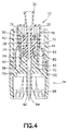
図1〜6を参照すると、流体の閉鎖的な移送のためのシステム10は、注射器アダプタ12、バイアルアダプタ14、および患者コネクタ16を含むが、システムは、IVバッグスパイクおよびIVラインアクセス装置を含むがこれらに限定されない他の構成要素を含んでもよい。システム10は、注射器、バイアル、IVバッグなどの様々な容器間の流体の閉鎖的な移送を容易にする。例えば、注射器アダプタ12は、注射器(図示せず)に固定されてもよく、バイアルアダプタ14は、薬剤を含むバイアル(図示せず)に固定されてもよい。後述するように、注射器アダプタ12は、バイアルアダプタ14に接続されて、システム10からの薬剤の排出およびシステムの使用者による薬剤への起こり得る曝露を防止しつつ、バイアルから注射器への薬剤の移送を行ってもよい。
Referring to FIGS. 1-6, the
図1〜4を参照すると、注射器アダプタ12は、第1端部22および第2端部24を有するハウジング20と、ハウジング20内に配置された膜ハウジング26と、ハウジング20内に配置されたカニューレ28と、ハウジング20の第1端部22から延びる注射器接続部30とを含む。膜ハウジング26は、ハウジング20内の第1位置と第2位置との間で移動可能である。膜ハウジング26の第1位置は、ハウジング20の第1端部22に隣接していてもよく、第2位置は、ハウジング20の第1および第2端部22、24の中間の位置であってもよい。膜ハウジング26は、膜32、34の間の空間を画定するために、第1および第2膜32、34を受容するが、膜ハウジング26は1つ以上の膜を含んでもよい。カニューレ28は、第1端部36と第2端部38とを有し、カニューレ28の第2端部38は、膜ハウジング26内に配置され、膜ハウジング26が第1位置にあるときに第1および第2膜32、34の間に配置され、膜ハウジング26が第2位置にあるときに膜ハウジング26の外側に配置される。カニューレ28の第2端部38は鈍い端部として示されていて、これは予め切れ目を入れられた膜を押し通すように構成されるが、カニューレ28の第2端部38は、膜を貫通するように構成された尖った端部であってもよい。カニューレ28の第1端部36は、注射器接続部30に接続され、かつ、注射器接続部30と流体連通するように構成されている。注射器接続部30は、注射器バレル(図示せず)に固定されるように構成されている。他の好適な接続部が利用されてもよいが、注射器接続部30は、雌のルアー接続部であってもよい。膜ハウジング26は、膜ハウジング26の移動が膜ハウジング26の第1位置と第2位置との間の移動に限定されるように、ハウジング20の内面によって画定されるトラックに沿って移動してもよい。
Referring to FIGS. 1 to 4, the
注射器アダプタ12のハウジング20は、ハウジング20の第1端部22に隣接して配置された第1部分40と、ハウジング20の第2端部24に隣接して配置された第2部分42とを含む。ハウジング20の第1部分40は、ハウジング20の第2部分42の内径に対して小さい内径を有する。ハウジング20は、ハウジング20の第1部分40と第2部分42との間に配置された移行部分44を含む。移行部分44は、他の好適な形状および構成が利用されてもよいが、円錐台形であってもよい。
The
再び図1〜図4を参照すると、バイアルアダプタ14は、第1端部54および第2端部56を有する本体52と、本体52の第2端部56から延びるバイアル接続部58と、本体52の第2端部56から延びるバイアルスパイク60と、本体52の第1端部54から延びるコレット接続部62とを含む。バイアル接続部58は、バイアルアダプタ52の本体52をバイアルまたは他の容器に固定するように構成されている。バイアルスパイク60は、コレット接続部62と流体連通する通路64を画定する。コレット接続部62は、注射器アダプタ12の膜ハウジング26に固定されるように構成されており、コレット接続部62は、コレット接続部62が膜ハウジング26を受容するように構成された第1位置と、コレット接続部62が膜ハウジング26に固定されるように構成された第2位置との間で移動可能である。コレット接続部62は、コレット本体70と、コレット本体70からバイアルアダプタ14の本体52の第1端部54から離れて延びる第1および第2腕部72、74とを含むが、コレット接続部62は、1つ以上の腕部を含んでもよい。図3および図4に示すように、第1および第2腕部72、74は、膜ハウジング26を受容するように構成された空間を画定する。コレット接続部62は、コレット接続部62がハウジング20の第1部分40内に配置されているときには第1位置(図3に示す)にあり、コレット接続部62がハウジング20の第2部分42内に配置されているときには第2位置(図4に示す)にある。コレット接続部62は、第1位置から第2位置に移行する際に、半径方向内向きに移動可能である。図3に示すように、コレット接続部62の腕部72、74は、コレット接続部62が注射器アダプタ12のハウジング20内に位置決めされたときに、腕部72、74を第1位置から第2位置に移動させるために、注射器アダプタ12のハウジング20の移行部分44と係合する。
Referring to FIGS. 1 to 4 again, the
コレット接続部62の第1および第2腕部72、74は、それぞれ、半径方向内向きに延びる突起76を含み、突起76は、コレット接続部62が第2位置にあるときに、脚部72、74によって画定された空間内に膜ハウジング26が受容された状態で、膜ハウジング26に係合するように構成されている。コレット本体70は、バイアルスパイク60と流体連通する通路78を画定している。コレット本体70は、コレット本体70の通路78をシールし、注射器アダプタ26の第2膜34と係合するように構成されたコレット膜80をさらに含む。特に、コレット接続部62が第2位置にあり、膜ハウジング26が第2位置にあるとき、注射器アダプタ12は、コレット接続部62の腕部72、74がハウジング20の第1部分40によって内側に強制的に押し込まれた状態で、バイアルアダプタ14に固定され、これによって第2膜34がコレット膜80に対して圧縮されて密閉された接続を形成する。膜ハウジング26が第2位置にあり、コレット接続部62と係合するとき、カニューレ28の第2端部38は、第2膜34、コレット膜80、およびコレット本体70の通路78内に押し込まれて、カニューレ28をバイアルスパイク60と流体連通するように配置される。
The first and
バイアルアダプタ14はまた、本体52の第1端部54から延びるコレットハウジング82を含み、コレット接続部62はコレットハウジング82内に配置される。コレットハウジング82は、バイアルアダプタ14が注射器アダプタ12に接続されるとき、すなわちコレット接続部62が膜ハウジング26に固定されるときに、注射器アダプタ12のハウジング20の一部を受容する。コレットハウジング82はインジケータ開口部84を画定し、注射器アダプタ12のハウジング20はインジケータ86を含む。インジケータ86は、コレット接続部62が第2位置にあり、かつ膜ハウジング26に固定されるとき、インジケータ開口部84を介して視認可能であり、バイアルアダプタ14が注射器アダプタ12に適切に接続されていることをユーザに示す表示を提供する。
The
図示されていないが、バイアルアダプタ14はまた、バイアルアダプタおよび注射器アダプタを介してバイアルから注射器への流体の移送中にバイアル内の圧力変化を防止するように構成された圧力等化設備を含んでもよい。典型的には、そのような圧力等化設備は、バイアルスパイク60内の別個のベントチャネルを利用し、これはバイアルアダプタ14に取り付けられているかまたはバイアルアダプタと一体的に形成された膨張可能なリザーバと連通する。膨張可能なリザーバは、バイアルからの流体の引出しに先立って空気で満たされてもよく、膨張可能なリザーバからバイアル内に空気が引き込まれ、それによってバイアル内に真空が形成されるのを防ぎ、これがバイアルの首部を変形させてバイアルからの薬剤の脱出を可能にすることができるようになっている。同様に、バイアル内の薬剤が再構成される必要がある場合、バイアルへの希釈剤の注入は、バイアルから膨張可能なリザーバ内に空気を移動させ、バイアルを加圧するというよりも薬剤をエアロゾル化させる。
Although not shown, the
図1、図5および図6を参照すると、患者コネクタ16は、第1端部92および第2端部94を有する本体90と、本体90を患者ライン(図示せず)に固定するように構成された患者接続部96とを含む。図示されていないが、患者コネクタ16は、バイアルアダプタ14と同じコレット接続部62を含む。患者コネクタ16は、上述したバイアルアダプタと同様の方法で注射器アダプタ12に接続される。患者コネクタ16は、他の好適な接続部を利用してもよいが、静脈内患者ラインの雌のルアー接続部に固定されるように構成された雄のルアー接続部であってもよい。バイアルアダプタ14と同様に、患者コネクタ16は、患者コネクタ16の本体90によって画定されるインジケータ開口部84を含む。図5に示すように、注射器アダプタ12のインジケータ86は、インジケータ開口部84を通しては視認可能でない。しかしながら、図6に示すように、注射器アダプタ12が患者接続部16に完全に固定されると、インジケータ86はインジケータ開口部84を通して視認可能である。
Referring to FIGS. 1, 5 and 6, the
図7を参照すると、バイアルアダプタ14は、バイアルアダプタ14を注射器アダプタ12にさらに固定するために、注射器アダプタ12のハウジング20内の対応する突起104と係合するように構成された突起102をさらに含んでもよい。突起102、104は、膜ハウジング26が第2位置にあるときに確実な接続を提供するために、バイアルアダプタ14と注射器アダプタ12との間にスナップフィット接続部を形成してもよい。
Referring to FIG. 7, the
図2〜4を参照すると、コレット接続部62の腕部72、74が注射器アダプタ12のハウジング20内で受容されるように、注射器アダプタ12をコレットハウジング82内に挿入することにより、注射器アダプタ12がバイアルアダプタ14に固定される。図3に示すように、コレット接続部62が注射器アダプタ12のハウジング20内に挿入されると、腕部72、74は第1位置にあり、膜ハウジング26を受容することができる。コレット接続部62の腕部72、74が注射器アダプタ12のハウジング20の移行部分44に達すると、腕部72、74は、コレット接続部62の第1位置からコレット接続部62の第2位置に向けて半径方向内向きに強制的に移動する。バイアルアダプタ14がさらに注射器アダプタ12内に挿入され、注射器アダプタ12のハウジング20の第1端部22に向かって挿入されると、コレット接続部62の腕部72、74の突起76が膜ハウジング26と係合し、第2膜34をコレット膜80に対して圧縮して密閉された接続部を形成し、バイアルアダプタ14および注射器アダプタ12を介した流体の閉鎖的な移送を可能にする。図4に示すように、膜ハウジング26が第2位置にある状態でコレット接続部62が注射器アダプタ12内に完全に挿入されると、カニューレ28は、第2膜34、コレット膜80を通って、バイアルスパイク60の通路64内に延び、それによって、カニューレ28とバイアルスパイク60との間の流体連通を提供する。接続ステップを逆にして、バイアルアダプタ14を注射器アダプタ12から切り離す。
Referring to FIGS. 2-4, the
本開示は、例示的な設計を有するものとして記載されてきたが、本開示は、本開示の精神および範囲をさらに修正することができる。したがって、本願は、その一般的な原理を用いた本開示の任意の変形、使用、または適応をカバーすることを意図している。さらに、本願は、本開示が属する技術において既知または慣例の範囲内にあり、かつ添付の特許請求の範囲の範囲内に収まるような、本開示からのそのような逸脱をカバーすることを意図している。 Although the present disclosure has been described as having an exemplary design, the present disclosure may further modify the spirit and scope of the present disclosure. Accordingly, the present application is intended to cover any modification, use, or adaptation of the present disclosure using that general principle. Further, the present application is intended to cover such deviations from the present disclosure that are within the scope of known or customary in the art to which the present disclosure belongs and within the scope of the appended claims. ing.
Claims (17)
バイアルアダプタであって、
第1端部および第2端部を有する本体、
前記本体の前記第2端部から延びるバイアル接続部であって、前記バイアル接続部が前記本体をバイアルに固定するように構成されている、バイアル接続部、
前記本体の前記第2端部から延びるバイアルスパイクであって、前記バイアルスパイクが通路を画定している、バイアルスパイク、および
前記本体の前記第1端部から延びるコレット接続部、
を備えたバイアルアダプタと、
注射器アダプタであって、
第1端部および第2端部を有するハウジング、
前記ハウジング内に配置された膜ハウジングであって、前記膜ハウジングが第1位置と第2位置との間で移動可能であり、前記膜ハウジングは少なくとも1つの膜を含む、膜ハウジング、
前記ハウジング内に配置されたカニューレであって、前記カニューレは第1端部および第2端部を有し、前記カニューレの前記第2端部は、前記膜ハウジングが第1位置にあるときに前記膜ハウジング内に配置され、前記膜ハウジングが第2位置にあるときに前記膜ハウジングの外側に配置される、カニューレ;および
前記ハウジングの前記第1端部から延びる注射器接続部であって、前記注射器接続部は、注射器バレルに固定されるように構成されている、注射器接続部、
を備えた注射器アダプタと、を備え、
前記コレット接続部が、前記コレット接続部が前記膜ハウジングを受容するように構成された第1位置と、前記コレット接続部が前記膜ハウジングに固定されるように構成された第2位置との間で移動可能である、システム。 A system for the closed transfer of liquids,
It ’s a vial adapter,
A body having a first end and a second end,
A vial connecting portion extending from the second end of the main body, wherein the vial connecting portion is configured to fix the main body to the vial.
A vial spike extending from the second end of the body, the vial spike defining a passage, and a collet connection extending from the first end of the body.
With vial adapter and
It ’s a syringe adapter,
A housing with a first end and a second end,
A membrane housing disposed within the housing, wherein the membrane housing is movable between a first position and a second position, wherein the membrane housing comprises at least one membrane.
A cannula located within the housing, wherein the cannula has a first end and a second end, the second end of the cannula being said when the membrane housing is in the first position. A cannula located inside the membrane housing and located outside the membrane housing when the membrane housing is in the second position; and a syringe connection extending from the first end of the housing, said syringe. The connection is configured to be secured to the syringe barrel, the syringe connection,
With syringe adapter, with ,
The collet connection is between a first position where the collet connection is configured to receive the membrane housing and a second position where the collet connection is configured to be fixed to the membrane housing. A system that can be moved with.
第1端部および第2端部を有する本体、
前記本体を患者ラインに固定するように構成された患者接続部、および
前記注射器アダプタの前記膜ハウジングに固定するように構成されたコレット接続部、
を備える、請求項1に記載のシステム。 Further comprising a patient connector, said patient connector
A body having a first end and a second end,
A patient connection configured to secure the body to the patient line, and a collet connection configured to secure the syringe adapter to the membrane housing.
The system according to claim 1.
前記本体の前記第2端部から延びるバイアル接続部であって、前記バイアル接続部が前記本体をバイアルに固定するように構成されている、バイアル接続部、
前記本体の前記第2端部から延びるバイアルスパイクであって、前記バイアルスパイクが通路を画定する、バイアルスパイク、および
前記本体の前記第1端部から延びるコレット接続部であって、前記コレット接続部が注射器アダプタに固定されるように構成されている、コレット接続部、
を備え、
前記コレット接続部が、前記コレット接続部が第1半径方向位置を有する第1位置と、前記コレット接続部が第2半径方向位置を有する第2位置との間で移動可能であり、
前記コレット接続部が、コレット本体と、前記コレット本体から離れて延びる第1および第2腕部とを備え、前記第1および第2腕部は、注射器アダプタの一部を受容するように構成された空間を画定している、バイアルアダプタ。 A body having a first end and a second end,
A vial connecting portion extending from the second end of the main body, wherein the vial connecting portion is configured to fix the main body to the vial.
A vial spike extending from the second end of the body, the vial spike defining a passage, and a collet connection extending from the first end of the body, the collet connection. Is configured to be secured to the syringe adapter, collet connection,
Equipped with
The collet connection is movable between a first position where the collet connection has a first radial position and a second position where the collet connection has a second radial position.
The collet connection comprises a collet body and first and second arms extending away from the collet body, the first and second arms configured to receive a portion of a syringe adapter. were we are defining a space, the vial adapter.
Applications Claiming Priority (3)
| Application Number | Priority Date | Filing Date | Title |
|---|---|---|---|
| US201862645279P | 2018-03-20 | 2018-03-20 | |
| US62/645,279 | 2018-03-20 | ||
| PCT/US2019/022941 WO2019183071A1 (en) | 2018-03-20 | 2019-03-19 | Connection arrangement for closed system transfer of fluids |
Publications (2)
| Publication Number | Publication Date |
|---|---|
| JP2021516122A JP2021516122A (en) | 2021-07-01 |
| JP6984034B2 true JP6984034B2 (en) | 2021-12-17 |
Family
ID=66001338
Family Applications (1)
| Application Number | Title | Priority Date | Filing Date |
|---|---|---|---|
| JP2020547165A Active JP6984034B2 (en) | 2018-03-20 | 2019-03-19 | Connection arrangement for closed system transfer of fluids |
Country Status (12)
| Country | Link |
|---|---|
| US (2) | US11413216B2 (en) |
| EP (1) | EP3768221B1 (en) |
| JP (1) | JP6984034B2 (en) |
| CN (1) | CN111867546B (en) |
| AU (1) | AU2019238179B2 (en) |
| BR (1) | BR112020017914A2 (en) |
| CA (2) | CA3174726A1 (en) |
| ES (1) | ES2961640T3 (en) |
| IL (1) | IL276642A (en) |
| MX (1) | MX2020009151A (en) |
| SG (1) | SG11202009005QA (en) |
| WO (1) | WO2019183071A1 (en) |
Families Citing this family (4)
| Publication number | Priority date | Publication date | Assignee | Title |
|---|---|---|---|---|
| USD907193S1 (en) * | 2018-02-21 | 2021-01-05 | Eli Lilly And Company | Secured medication transfer set |
| DE102020202939A1 (en) | 2020-03-06 | 2021-09-09 | B. Braun Melsungen Aktiengesellschaft | Coupling element for a closed fluid transfer system, mating coupling element for such a coupling element and coupling system |
| EP4237047A1 (en) * | 2020-10-28 | 2023-09-06 | Becton, Dickinson and Company | Membrane with guide surface |
| WO2023170680A1 (en) | 2022-03-08 | 2023-09-14 | Equashield Medical Ltd | Fluid transfer station in a robotic pharmaceutical preparation system |
Family Cites Families (17)
| Publication number | Priority date | Publication date | Assignee | Title |
|---|---|---|---|---|
| US4005739A (en) * | 1975-10-20 | 1977-02-01 | Baxter Travenol Laboratories, Inc. | Supplemental medication indication cap for solution containers and the like |
| US4373559A (en) * | 1980-12-04 | 1983-02-15 | Abbott Laboratories | Apparatus for pressurizing an additive transfer device |
| US4507113A (en) * | 1982-11-22 | 1985-03-26 | Derata Corporation | Hypodermic jet injector |
| US4759756A (en) * | 1984-09-14 | 1988-07-26 | Baxter Travenol Laboratories, Inc. | Reconstitution device |
| DE69712499T2 (en) * | 1996-01-11 | 2002-11-14 | Duoject Inc | DISPENSING SYSTEM FOR MEDICINAL PRODUCTS PACKED IN PHARMACEUTICAL VIALS |
| EP1687203A4 (en) | 2003-10-30 | 2009-02-25 | Teva Medical Ltd | Safety drug handling device |
| JP4857853B2 (en) * | 2006-03-28 | 2012-01-18 | ニプロ株式会社 | Transfer tool kit and adapter member |
| CN102784058B (en) | 2007-04-23 | 2014-12-17 | 普拉斯特米德有限公司 | Method and apparatus for contamination-free transfer of a hazardous drug |
| US8864725B2 (en) | 2009-03-17 | 2014-10-21 | Baxter Corporation Englewood | Hazardous drug handling system, apparatus and method |
| IL217091A0 (en) * | 2011-12-19 | 2012-02-29 | Medimop Medical Projects Ltd | Vial adapter for use with syringe having widened distal syringe tip |
| AU2013290038B2 (en) * | 2012-07-12 | 2015-10-29 | Antares Pharma, Inc. | Liquid-transfer adapter beveled spike |
| US10022301B2 (en) | 2013-03-15 | 2018-07-17 | Becton Dickinson and Company Ltd. | Connection system for medical device components |
| CA3179530A1 (en) | 2013-07-19 | 2015-01-22 | Icu Medical, Inc. | Pressure-regulating fluid transfer systems and methods |
| EP3065812B1 (en) * | 2013-11-06 | 2020-01-01 | Becton Dickinson and Company Limited | Connection apparatus for a medical device |
| US9636278B2 (en) * | 2013-11-06 | 2017-05-02 | Becton Dickinson and Company Limited | System for closed transfer of fluids with a locking member |
| US10376654B2 (en) * | 2014-04-21 | 2019-08-13 | Becton Dickinson and Company Limited | System for closed transfer of fluids and membrane arrangements for use thereof |
| CA2946562C (en) | 2014-04-21 | 2019-03-26 | Becton Dickinson and Company Limited | System with adapter for closed transfer of fluids |
-
2019
- 2019-03-19 ES ES19715302T patent/ES2961640T3/en active Active
- 2019-03-19 CA CA3174726A patent/CA3174726A1/en active Pending
- 2019-03-19 MX MX2020009151A patent/MX2020009151A/en unknown
- 2019-03-19 EP EP19715302.6A patent/EP3768221B1/en active Active
- 2019-03-19 CA CA3090905A patent/CA3090905C/en active Active
- 2019-03-19 WO PCT/US2019/022941 patent/WO2019183071A1/en unknown
- 2019-03-19 US US16/357,996 patent/US11413216B2/en active Active
- 2019-03-19 SG SG11202009005QA patent/SG11202009005QA/en unknown
- 2019-03-19 JP JP2020547165A patent/JP6984034B2/en active Active
- 2019-03-19 CN CN201980019672.8A patent/CN111867546B/en active Active
- 2019-03-19 AU AU2019238179A patent/AU2019238179B2/en active Active
- 2019-03-19 BR BR112020017914-0A patent/BR112020017914A2/en active Search and Examination
-
2020
- 2020-08-11 IL IL276642A patent/IL276642A/en unknown
-
2022
- 2022-07-11 US US17/861,851 patent/US20220339069A1/en active Pending
Also Published As
| Publication number | Publication date |
|---|---|
| CN111867546B (en) | 2023-09-12 |
| ES2961640T3 (en) | 2024-03-13 |
| SG11202009005QA (en) | 2020-10-29 |
| AU2019238179B2 (en) | 2021-12-23 |
| IL276642A (en) | 2020-09-30 |
| CA3090905A1 (en) | 2019-09-26 |
| US20190290543A1 (en) | 2019-09-26 |
| CN111867546A (en) | 2020-10-30 |
| BR112020017914A2 (en) | 2020-12-22 |
| EP3768221A1 (en) | 2021-01-27 |
| WO2019183071A1 (en) | 2019-09-26 |
| JP2021516122A (en) | 2021-07-01 |
| CA3090905C (en) | 2022-12-13 |
| US20220339069A1 (en) | 2022-10-27 |
| MX2020009151A (en) | 2021-01-08 |
| US11413216B2 (en) | 2022-08-16 |
| EP3768221B1 (en) | 2023-10-25 |
| CA3174726A1 (en) | 2019-09-26 |
| AU2019238179A1 (en) | 2020-09-03 |
Similar Documents
| Publication | Publication Date | Title |
|---|---|---|
| JP7004757B2 (en) | System for closed transfer of fluid, including locking members | |
| JP6984034B2 (en) | Connection arrangement for closed system transfer of fluids | |
| JP6952671B2 (en) | Fluid closure transfer system with connector | |
| JP6371369B2 (en) | System for closed transfer of fluid | |
| JP2018134557A (en) | System with adaptor for closed transfer of fluids | |
| US20240024201A1 (en) | Syringe Adapter with Aspiration Assembly | |
| US20230301871A1 (en) | Membrane for Closed System Transfer Device |
Legal Events
| Date | Code | Title | Description |
|---|---|---|---|
| A621 | Written request for application examination |
Free format text: JAPANESE INTERMEDIATE CODE: A621 Effective date: 20200909 |
|
| A131 | Notification of reasons for refusal |
Free format text: JAPANESE INTERMEDIATE CODE: A131 Effective date: 20210713 |
|
| A521 | Request for written amendment filed |
Free format text: JAPANESE INTERMEDIATE CODE: A523 Effective date: 20211012 |
|
| TRDD | Decision of grant or rejection written | ||
| A01 | Written decision to grant a patent or to grant a registration (utility model) |
Free format text: JAPANESE INTERMEDIATE CODE: A01 Effective date: 20211026 |
|
| A61 | First payment of annual fees (during grant procedure) |
Free format text: JAPANESE INTERMEDIATE CODE: A61 Effective date: 20211124 |
|
| R150 | Certificate of patent or registration of utility model |
Ref document number: 6984034 Country of ref document: JP Free format text: JAPANESE INTERMEDIATE CODE: R150 |