JP6983816B2 - Aerosol generators and aerosol generators with pistons - Google Patents
Aerosol generators and aerosol generators with pistons Download PDFInfo
- Publication number
- JP6983816B2 JP6983816B2 JP2018561040A JP2018561040A JP6983816B2 JP 6983816 B2 JP6983816 B2 JP 6983816B2 JP 2018561040 A JP2018561040 A JP 2018561040A JP 2018561040 A JP2018561040 A JP 2018561040A JP 6983816 B2 JP6983816 B2 JP 6983816B2
- Authority
- JP
- Japan
- Prior art keywords
- aerosol
- housing
- heating chamber
- article
- forming substrate
- Prior art date
- Legal status (The legal status is an assumption and is not a legal conclusion. Google has not performed a legal analysis and makes no representation as to the accuracy of the status listed.)
- Active
Links
- 0 *C1=CCCCC1 Chemical compound *C1=CCCCC1 0.000 description 1
- UAEPNZWRGJTJPN-UHFFFAOYSA-N CC1CCCCC1 Chemical compound CC1CCCCC1 UAEPNZWRGJTJPN-UHFFFAOYSA-N 0.000 description 1
Images


Classifications
-
- A—HUMAN NECESSITIES
- A24—TOBACCO; CIGARS; CIGARETTES; SIMULATED SMOKING DEVICES; SMOKERS' REQUISITES
- A24F—SMOKERS' REQUISITES; MATCH BOXES; SIMULATED SMOKING DEVICES
- A24F40/00—Electrically operated smoking devices; Component parts thereof; Manufacture thereof; Maintenance or testing thereof; Charging means specially adapted therefor
- A24F40/40—Constructional details, e.g. connection of cartridges and battery parts
- A24F40/42—Cartridges or containers for inhalable precursors
-
- A—HUMAN NECESSITIES
- A24—TOBACCO; CIGARS; CIGARETTES; SIMULATED SMOKING DEVICES; SMOKERS' REQUISITES
- A24D—CIGARS; CIGARETTES; TOBACCO SMOKE FILTERS; MOUTHPIECES FOR CIGARS OR CIGARETTES; MANUFACTURE OF TOBACCO SMOKE FILTERS OR MOUTHPIECES
- A24D1/00—Cigars; Cigarettes
- A24D1/14—Tobacco cartridges for pipes
-
- A—HUMAN NECESSITIES
- A24—TOBACCO; CIGARS; CIGARETTES; SIMULATED SMOKING DEVICES; SMOKERS' REQUISITES
- A24D—CIGARS; CIGARETTES; TOBACCO SMOKE FILTERS; MOUTHPIECES FOR CIGARS OR CIGARETTES; MANUFACTURE OF TOBACCO SMOKE FILTERS OR MOUTHPIECES
- A24D1/00—Cigars; Cigarettes
- A24D1/20—Cigarettes specially adapted for simulated smoking devices
-
- A—HUMAN NECESSITIES
- A24—TOBACCO; CIGARS; CIGARETTES; SIMULATED SMOKING DEVICES; SMOKERS' REQUISITES
- A24F—SMOKERS' REQUISITES; MATCH BOXES; SIMULATED SMOKING DEVICES
- A24F40/00—Electrically operated smoking devices; Component parts thereof; Manufacture thereof; Maintenance or testing thereof; Charging means specially adapted therefor
- A24F40/20—Devices using solid inhalable precursors
-
- A—HUMAN NECESSITIES
- A24—TOBACCO; CIGARS; CIGARETTES; SIMULATED SMOKING DEVICES; SMOKERS' REQUISITES
- A24F—SMOKERS' REQUISITES; MATCH BOXES; SIMULATED SMOKING DEVICES
- A24F40/00—Electrically operated smoking devices; Component parts thereof; Manufacture thereof; Maintenance or testing thereof; Charging means specially adapted therefor
- A24F40/40—Constructional details, e.g. connection of cartridges and battery parts
- A24F40/46—Shape or structure of electric heating means
-
- A—HUMAN NECESSITIES
- A24—TOBACCO; CIGARS; CIGARETTES; SIMULATED SMOKING DEVICES; SMOKERS' REQUISITES
- A24F—SMOKERS' REQUISITES; MATCH BOXES; SIMULATED SMOKING DEVICES
- A24F47/00—Smokers' requisites not otherwise provided for
-
- A—HUMAN NECESSITIES
- A24—TOBACCO; CIGARS; CIGARETTES; SIMULATED SMOKING DEVICES; SMOKERS' REQUISITES
- A24F—SMOKERS' REQUISITES; MATCH BOXES; SIMULATED SMOKING DEVICES
- A24F7/00—Mouthpieces for pipes; Mouthpieces for cigar or cigarette holders
-
- A—HUMAN NECESSITIES
- A61—MEDICAL OR VETERINARY SCIENCE; HYGIENE
- A61M—DEVICES FOR INTRODUCING MEDIA INTO, OR ONTO, THE BODY; DEVICES FOR TRANSDUCING BODY MEDIA OR FOR TAKING MEDIA FROM THE BODY; DEVICES FOR PRODUCING OR ENDING SLEEP OR STUPOR
- A61M15/00—Inhalators
- A61M15/06—Inhaling appliances shaped like cigars, cigarettes or pipes
Description
本発明は、エアロゾル発生装置、およびこうした装置で使用するエアロゾル発生装置に関する。 The present invention relates to an aerosol generator and an aerosol generator used in such an apparatus.
エアロゾル形成基体が装置の加熱チャンバーの中へと導入されるエアロゾル発生システムは周知である。その中で、エアロゾル形成基体は加熱され、物質は基体から蒸発され、これによって物質は吸入可能なエアロゾルを形成しうる。エアロゾル形成基体は、容器に入っていない形態で提供されてもよく、または小さいポットの中で提供されてもよい。容器に入っていない形態にある基体は、加熱チャンバー内に「純粋な」基体が存在すること、および基体の量および混合がユーザーによって選ばれうるという利点を提供する。しかし、容器に入っていない基体の量を調節することはユーザーの体験に依存するが、一貫性のないユーザー体験を常に引き起こす。清浄な適用および一貫性のあるユーザー体験のために、所定の量のエアロゾル形成基体がポット内に提供されてもよく、このポットは加熱チャンバーの中へと挿入される。これらの適用では、ポットの材料も加熱され、またポットは蒸発した物質の漏れ出しを制限する場合がある。 Aerosol generation systems in which an aerosol-forming substrate is introduced into the heating chamber of the device are well known. In it, the aerosol-forming substrate is heated and the substance evaporates from the substrate, whereby the substance can form an inhalable aerosol. The aerosol-forming substrate may be provided in a form that is not in a container or may be provided in a small pot. The substrate in a non-container form provides the advantage of the presence of a "pure" substrate in the heating chamber and the amount and mixing of the substrate can be chosen by the user. However, adjusting the amount of substrate that is not in the container depends on the user experience, but always causes an inconsistent user experience. For a clean application and a consistent user experience, a predetermined amount of aerosol-forming substrate may be provided in the pot, which is inserted into the heating chamber. In these applications, the material of the pot is also heated and the pot may limit the leakage of evaporated material.
従って、先行技術の解決策の利点を有するが、それらの制限のないエアロゾル発生物品およびエアロゾル発生装置を有することが望ましいことになる。特に、好都合なことに一貫した量のエアロゾル形成基体を加熱チャンバーの中へと注入し、一貫性のあるユーザー体験を提供するという利点を提供する、エアロゾル発生物品およびエアロゾル発生装置を有することが望ましいことになる。 Therefore, it would be desirable to have aerosol-generating articles and aerosol-generating devices that have the advantages of prior art solutions but are not limited to them. In particular, it is desirable to have aerosol generators and aerosol generators that conveniently inject a consistent amount of aerosol-forming substrate into the heating chamber to provide the advantage of providing a consistent user experience. It will be.
本発明によると、開放端を有するハウジングを備えるエアロゾル発生物品が提供されている。ハウジングは、たばこ消費財とすることができるエアロゾル形成基体を保持するためのくぼみを備える。エアロゾル発生物品は、ハウジングの中でハウジングの開放端の方向へと移動可能なピストンをさらに備える。ピストンを物品のハウジングの開放端の方向へと押すことによって、くぼみの中に収容されていてもよいエアロゾル形成基体はハウジングの開放端を通して、かつ物品の外へ押し出されてもよい。物品は、エアロゾル発生装置、特に本発明による、および本明細書に記載の通りのエアロゾル発生装置で使用するように構成されていることが好ましい。 According to the present invention, there is provided an aerosol generating article with a housing having an open end. The housing has a recess for holding an aerosol-forming substrate that can be a tobacco consumer good. The aerosol-generating article further comprises a piston that is movable within the housing towards the open end of the housing. By pushing the piston toward the open end of the housing of the article, the aerosol-forming substrate may be contained in the recess and may be pushed out of the article through the open end of the housing. The article is preferably configured for use in aerosol generators, in particular according to the present invention and as described herein.
ハウジング内のくぼみは、くぼみの一方の端を形成するピストンの基部と、内側ハウジング壁と、くぼみの反対側の端を形成するハウジングの開放端とによって画定されてもよい。 The recess in the housing may be defined by the base of the piston forming one end of the recess, the inner housing wall and the open end of the housing forming the opposite end of the recess.
物品は所定の量のエアロゾル形成基体を含んでもよく、有利なことにくぼみのサイズによって画定される。エアロゾル形成基体をくぼみの中へと充填する前に、エアロゾル形成基体の量は測定されてもよく、ひいては特定のエアロゾル発生装置で同一のエアロゾル形成物品を使用するたびに一貫性のあるユーザー体験を提供しうる。さらに、くぼみ内のエアロゾル形成基体は、その即時の使用までハウジングによって機械的に保護される。基体はまた、例えば湿度または酸化などのその他の環境の影響からも保護されることが好ましい。これは、例えば保護箔の提供によって実現されてもよく、この場合物品は保護箔で密封されることができ、または例えばハウジングの開放端を密封することによって、エアロゾル形成基体を備えるくぼみが密封されてもよい。こうした保護箔または密封は、物品の使用の前に取り除かれてもよい。 The article may contain a predetermined amount of aerosol-forming substrate, which is advantageously defined by the size of the indentation. The amount of aerosol-forming substrate may be measured prior to filling the aerosol-forming substrate into the recess, thus providing a consistent user experience each time the same aerosol-forming article is used in a particular aerosol generator. Can be provided. In addition, the aerosol-forming substrate in the recess is mechanically protected by the housing until its immediate use. The substrate is also preferably protected from other environmental effects such as humidity or oxidation. This may be achieved, for example, by providing a protective foil, in which case the article can be sealed with a protective foil, or, for example, by sealing the open end of the housing, the recess with the aerosol-forming substrate is sealed. You may. These protective foils or seals may be removed prior to use of the article.
ハウジング内に配置されたピストンは、エアロゾル形成基体をくぼみの外へ、およびハウジングの外へと動かすのを容易にする。これはピストンの短い(例えば、くぼみの長さにわたる)直線運動によって達成されてもよい。 Pistons located within the housing facilitate the movement of the aerosol-forming substrate out of the indentation and out of the housing. This may be achieved by a short linear motion of the piston (eg, over the length of the indentation).
たばこ消費財などのエアロゾル形成基体は、基体を受けるように構成されたエアロゾル発生装置の加熱チャンバーの中へと直接押されることが好ましい。このようにして、明確に定義された量のエアロゾル形成基体が装置の使用準備において加熱チャンバーへと供給されて、一貫性のあるユーザー体験を提供してもよい。以下により詳細に概説されるように、エアロゾル発生装置の単純な設計が支援される。 Aerosol-forming substrates such as tobacco consumer goods are preferably pushed directly into the heating chamber of an aerosol generator configured to receive the substrate. In this way, a well-defined amount of aerosol-forming substrate may be fed into the heating chamber in preparation for use of the device to provide a consistent user experience. A simple design of the aerosol generator is assisted, as outlined in more detail below.
エアロゾル発生物品は、例えば同軸に配置された二つの円筒であるハウジングおよびピストン、または他の幾何学的形態のピストンおよびハウジングによって実現されてもよい。こうした実施形態において、ハウジングは中空円筒であり、またピストンは中実円筒であることが好ましい。 Aerosol-generating articles may be realized, for example, by housings and pistons that are two coaxially arranged cylinders, or pistons and housings in other geometric forms. In these embodiments, the housing is preferably a hollow cylinder and the piston is preferably a solid cylinder.
ハウジングとピストンは精密なはめ合わせを形成し、その結果エアロゾル形成基体がピストンとハウジングの間を通過しないことが好ましい。ハウジング内のくぼみは、ピストンの基部の下に形成されてもよい。しかしながら、ピストンとハウジングの間に気流通路が提供されてもよく、空気またはエアロゾルを含有する空気は、この通路を通過する。 It is preferred that the housing and piston form a precise fit so that the aerosol-forming substrate does not pass between the piston and housing. The indentation in the housing may be formed under the base of the piston. However, an airflow passage may be provided between the piston and the housing, and air containing air or aerosol will pass through this passage.
ピストンおよびハウジングの配置およびサイズに依存して、ピストンは完全にハウジングの内側に配置されてもよく、またはハウジングから突出してもよい。 Depending on the placement and size of the piston and housing, the piston may be located entirely inside the housing or may protrude from the housing.
ピストンは、好ましくは物品の使用前または使用後、すなわちエアロゾル形成基体をくぼみから外へ押し出す前または後に、ハウジングの端と同一平面で配置されてもよい。ハウジングの端と同一平面で配置されたピストンは、物品または基体の状態(例えば、エアロゾル形成基体の位置など)を示すために動作制御として使用されてもよい。ハウジングの一方の端と同一平面で配置されたピストンは、貯蔵のために物品の積み重ねを単純化する場合があり、また基体が物品内にまだ存在していること、または基体がハウジングの外に完全に押し出されたことを示す場合がある。突出しているピストンは、基体をハウジングの外へと押し出すために簡単にアクセスすることができる。 The piston may be placed in a plane flush with the end of the housing, preferably before or after use of the article, i.e., before or after pushing the aerosol-forming substrate out of the recess. The piston, which is coplanar with the end of the housing, may be used as motion control to indicate the condition of the article or substrate (eg, the position of the aerosol-forming substrate). Pistons coplanar with one end of the housing may simplify stacking of articles for storage, and the substrate may still be present within the article, or the substrate may be outside the housing. It may indicate that it has been completely extruded. The protruding piston can be easily accessed to push the substrate out of the housing.
ハウジングの長さはピストンの長さと同一であるか、またはピストンの長さよりも長いことが好ましい。エアロゾル形成基体が物品のくぼみの中に貯蔵される時、ピストンはその移動範囲の一方の極端な端に配置されてもよい。エアロゾル形成基体がくぼみの外へ完全に押し出された時、ピストンはその移動範囲のもう一方の極端な端に配置されてもよい。 The length of the housing is preferably equal to or longer than the length of the piston. When the aerosol-forming substrate is stored in the recess of the article, the piston may be placed at one extreme end of its range of motion. When the aerosol-forming substrate is completely pushed out of the recess, the piston may be placed at the other extreme end of its range of motion.
エアロゾル発生物品は、物品を通した少なくとも一つの気流チャネルを備えてもよい。気流チャネルは物品の一方の端から物品の反対側の端に延びることが好ましい。こうした気流チャネルは、エアロゾル形成基体から蒸発した物質が装置内で加熱チャンバーから物品を通して、さらに下流へ、例えばマウスピースの中へと、またはマウスピースを通って通過することを可能にする場合がある。こうした気流チャネルはまた、新鮮な空気が物品を通過し、加熱チャンバーの中に入り、加熱チャンバー内で発生した蒸発した基体を捕らえることを可能にする場合がある。 Aerosol-generating articles may include at least one airflow channel through the article. The airflow channel preferably extends from one end of the article to the opposite end of the article. These airflow channels may allow material evaporated from the aerosol-forming substrate to pass through the article from the heating chamber and further downstream, for example into the mouthpiece, or through the mouthpiece within the device. .. Such airflow channels may also allow fresh air to pass through the article, enter the heating chamber, and capture the evaporated substrate generated within the heating chamber.
エアロゾル発生物品は、物品を通る複数の気流チャネルを備えてもよい。 The aerosol-generating article may include multiple airflow channels through the article.
気流チャネルは、ピストンとハウジングのサイズおよび相対的な配置に依存して、例えばハウジングの開放端からハウジングの反対側の端まで、ピストンの一方の端からピストンの反対側の端まで、ハウジングの開放端からピストンの近位端まで、延びてもよい。 The airflow channel depends on the size and relative placement of the piston and housing, for example from the open end of the housing to the opposite end of the housing, from one end of the piston to the opposite end of the piston, the opening of the housing. It may extend from the end to the proximal end of the piston.
少なくとも一つの気流チャネルは、例えばピストンに沿って配置されてもよい。チャネルはピストンの中に配置されてもよく、例えば中央に配置されたチャネルを形成する。チャネル(複数可)はまた、例えば外側ピストン壁または内側ハウジング壁において、ピストンとハウジングの間に配置されてもよい。複数のチャネルは、物品内で対称に、かつ規則的に配置されてもよい。 The at least one airflow channel may be arranged, for example, along the piston. The channel may be arranged in the piston, for example forming a centrally arranged channel. The channel (s) may also be located between the piston and the housing, for example on the outer piston wall or the inner housing wall. The plurality of channels may be arranged symmetrically and regularly within the article.
物品内の気流チャネルは、所望のサイズの気流チャネルを提供するために、例えばピストンと内側ハウジング壁の間の製造公差を選択することによって提供されてもよい。 The airflow channel within the article may be provided, for example, by selecting a manufacturing tolerance between the piston and the inner housing wall to provide the airflow channel of the desired size.
エアロゾル発生物品はくぼみの中に提供されたエアロゾル形成基体を備えることが好ましい。くぼみは、エアロゾル形成基体で充填されることが好ましい。物品内のエアロゾル形成基体は、ハウジングの開放端と同一平面であってもよい。 The aerosol-generating article preferably comprises the provided aerosol-forming substrate in the recess. The recess is preferably filled with an aerosol-forming substrate. The aerosol-forming substrate in the article may be flush with the open end of the housing.
エアロゾル発生物品は、エアロゾル発生物品の加熱チャンバーの一回の充填である所定の量のエアロゾル形成基体を備えてもよい。一回の充填は一回のユーザー体験を提供することが好ましい。特に、エアロゾル発生物品は、所定の量のエアロゾル形成基体を含む充填カートリッジであってもよい。所定の量のエアロゾル形成基体は、エアロゾル発生装置を使用する前またはユーザー体験を開始する前のピストンの一回の移動動作で、エアロゾル発生装置の加熱チャンバーの中へと充填されることが好ましい。 The aerosol-generating article may include a predetermined amount of aerosol-forming substrate, which is a single filling of the heating chamber of the aerosol-generating article. It is preferable that one filling provides a one-time user experience. In particular, the aerosol-generating article may be a filled cartridge containing a predetermined amount of aerosol-forming substrate. It is preferred that the predetermined amount of aerosol-forming substrate is filled into the heating chamber of the aerosol generator with a single movement of the piston before using the aerosol generator or initiating the user experience.
エアロゾル形成基体は一括でまたはまとめて、エアロゾル発生物品から加熱チャンバーの中へと、特にピストンの一回の移動動作によって、移動可能であってもよい。エアロゾル発生物品およびエアロゾル発生装置は、形状を保持するまたは寸法的に安定した方法でエアロゾル形成基体を移動するおよび受けるように構成されていることが好ましく、すなわちその結果エアロゾル形成基体は実質的に変形することなくエアロゾル発生物品から加熱チャンバーの中へと移動可能である。ハウジングおよびピストンを形成する材料は同一であってもよく、または異なってもよい。ハウジングおよびピストンを形成する材料は、エアロゾル発生装置内に呈される高温、例えばこうした装置の動作温度に耐える能力を有する任意の材料であってもよい。ハウジングおよびピストンを形成する材料はポリマー、例えば摂氏約150度の温度に耐える能力を有するポリマーであってもよい。 The aerosol-forming substrates may be movable in bulk or in bulk from the aerosol-generating article into the heating chamber, especially by a single movement of the piston. Aerosol-generating articles and aerosol generators are preferably configured to move and receive aerosol-forming substrates in a shape-retaining or dimensionally stable manner, i.e., resulting in substantial deformation of the aerosol-forming substrate. It is possible to move from the aerosol-generating article into the heating chamber without any effort. The materials forming the housing and piston may be the same or different. The material forming the housing and piston may be any material capable of withstanding the high temperatures exhibited within the aerosol generator, such as the operating temperature of such devices. The material forming the housing and piston may be a polymer, eg, a polymer capable of withstanding temperatures of about 150 degrees Celsius.
物品に適切な材料には例えば、紙もしくは厚紙、シリコンゴム、酢酸セルロース、セラミックもしくはガラス、またはPEEKもしくはポリイミドなどの高温ポリマーが含まれてもよい。随意に、コスト低減のために、ヒーターまたは加熱チャンバーと接触する物品の一部分は耐熱であってもよく、またヒーターまたは加熱チャンバーと接触しない部品は、より安価な非耐熱プラスチック材料であってもよい。 Suitable materials for the article may include, for example, paper or cardboard, silicone rubber, cellulose acetate, ceramic or glass, or high temperature polymers such as PEEK or polyimide. Optionally, for cost reduction, parts of the article that come into contact with the heater or heating chamber may be heat resistant, and parts that do not come into contact with the heater or heating chamber may be cheaper non-heat resistant plastic materials. ..
エアロゾル形成基体は、エアロゾルを形成することができる揮発性化合物を放出する能力を有する基体であることが好ましい。揮発性化合物はエアロゾル形成基体の加熱によって放出される。 The aerosol-forming substrate is preferably a substrate capable of releasing volatile compounds capable of forming an aerosol. Volatile compounds are released by heating the aerosol-forming substrate.
エアロゾル形成基体は非液体、特に固体エアロゾル形成基体である。エアロゾル形成基体は加熱に伴い基体から放出される揮発性のたばこ風味化合物を含む、たばこ含有材料を含んでもよい。別の方法として、エアロゾル形成基体は非たばこ材料を含んでもよい。エアロゾル形成基体は、エアロゾル形成体をさらに含んでもよい。適切なエアロゾル形成体の例は、グリセリンおよびプロピレングリコールである。 Aerosol-forming substrates are non-liquid, especially solid aerosol-forming substrates. The aerosol-forming substrate may include a tobacco-containing material containing a volatile tobacco-flavored compound released from the substrate upon heating. Alternatively, the aerosol-forming substrate may comprise a non-tobacco material. The aerosol-forming substrate may further contain an aerosol-forming body. Examples of suitable aerosol forming bodies are glycerin and propylene glycol.
エアロゾル形成基体は、例えば薬草の葉、たばこ葉、たばこの茎の断片、再構成たばこ、均質化したたばこ、押出成形たばこ、および膨化たばこのうちの一つ以上を含有する粉末、顆粒、ペレット、断片、スパゲッティ撚糸、細片またはシートのうちの一つ以上を含んでもよい。 Aerosol-forming substrates include, for example, powders, granules, pellets, containing one or more of herbal leaves, tobacco leaves, tobacco stem fragments, reconstituted tobacco, homogenized tobacco, extruded tobacco, and puffed tobacco. It may contain one or more of fragments, tobacco twists, strips or sheets.
随意に、エアロゾル形成基体は、そのエアロゾル形成基体の加熱に伴い放出される、追加的なたばこまたは非たばこ揮発性風味化合物を含有してもよい。固体エアロゾル形成基体はまた、例えば追加的なたばこまたは非たばこ揮発性風味化合物を含むカプセルを含んでもよく、こうしたカプセルは固体エアロゾル形成基体バルクの加熱中に溶けてもよい。 Optionally, the aerosol-forming substrate may contain additional tobacco or non-tobacco volatile flavor compounds released upon heating of the aerosol-forming substrate. The solid aerosol-forming substrate may also contain, for example, capsules containing additional tobacco or non-tobacco volatile flavor compounds, such capsules which may be melted during heating of the solid aerosol-forming substrate bulk.
エアロゾル形成基体は、その他の添加物およびニコチンまたは風味剤などの成分を含んでもよい。 The aerosol-forming substrate may contain other additives and components such as nicotine or flavoring agents.
エアロゾル形成基体はニコチンおよび少なくとも一つのエアロゾル形成体を含むことが好ましい。 The aerosol-forming substrate preferably contains nicotine and at least one aerosol-forming body.
エアロゾル形成体はまた、基体がたばこ粒子を含むたばこ由来の製品で構成されている時にエアロゾル形成基体内に望ましいレベルの水分を維持するのに役立つ、湿潤剤タイプの特性も有してもよい。特に、一部のエアロゾル形成体は、湿潤剤として機能する吸湿性材料、すなわち湿潤剤を含有する基体を湿った状態に保つのに役立つ材料である。 Aerosol-forming bodies may also have wetting agent-type properties that help maintain the desired level of moisture within the aerosol-forming substrate when the substrate is composed of tobacco-derived products containing tobacco particles. In particular, some aerosol-forming bodies are hygroscopic materials that function as wetting agents, i.e. materials that help keep the substrate containing the wetting agent moist.
一つ以上のエアロゾル形成体を組み合わせて、その組み合わせたエアロゾル形成体の一つ以上の特性を利用してもよい。例えば、有効成分を運ぶトリアセチンの能力とグリセロールの保湿性を利用するためにトリアセチンをグリセロールおよび水と組み合わせてもよい。 One or more aerosol-forming bodies may be combined to take advantage of one or more properties of the combined aerosol-forming bodies. For example, triacetin may be combined with glycerol and water to take advantage of the ability of triacetin to carry the active ingredient and the moisturizing properties of glycerol.
エアロゾル形成体はポリオール、グリコールエーテル、ポリオールエステル、エステル、および脂肪酸から選択されてよく、また以下の化合物、すなわちグリセロール、エリスリトール、1,3−ブチレングリコール、テトラエチレングリコール、トリエチレングリコール、クエン酸トリエチル、プロピレンカーボネート、ラウリン酸エチル、トリアセチン、メソ−エリスリトール、ジアセチン混合物、スベリン酸ジエチル、クエン酸トリエチル、安息香酸ベンジル、フェニル酢酸ベンジル、バニリン酸エチル、トリブチリン、酢酸ラウリル、ラウリン酸、ミリスチン酸、およびプロピレングリコールのうちの一つ以上を含んでよい。 The aerosol-forming body may be selected from polyols, glycol ethers, polyol esters, esters, and fatty acids, and the following compounds: glycerol, erythritol, 1,3-butylene glycol, tetraethylene glycol, triethylene glycol, triethyl citrate. , Propylene carbonate, ethyl laurate, triacetin, meso-erythritol, diacetin mixture, diethyl sverate, triethyl citrate, benzyl benzoate, benzyl phenylacetate, ethyl vanirate, tributyrin, lauryl acetate, lauric acid, myristic acid, and propylene It may contain one or more of glycols.
エアロゾル形成基体は、物品のくぼみの中へと嵌合するように集められた、一つ以上の均質化したたばこ材料シートを含んでもよい。エアロゾル形成基体は、均質化したたばこ材料の捲縮したシートの集合体を含んでもよい。 The aerosol-forming substrate may include one or more homogenized tobacco material sheets collected to fit into the recesses of the article. The aerosol-forming substrate may include an aggregate of crimped sheets of homogenized tobacco material.
たばこシートはキャストリーフであることが好ましい。キャストリーフは、たばこ粒子、繊維粒子、エアロゾル形成体、結合剤、および例えば風味も含むスラリーから形成される、再構成たばこの一形態である。 The tobacco sheet is preferably a cast leaf. Cast leaf is a form of reconstituted tobacco formed from a slurry containing tobacco particles, fiber particles, aerosol-forming bodies, binders, and eg flavors.
エアロゾル形成基体のシートは、例えば細片へと切断されてもよく、また続いてくぼみの中へと挿入され、かつその定位置に、例えば基体と物品ハウジングまたは結合剤とのぴったりとした嵌合によって固定されてもよい。 The sheet of the aerosol-forming substrate may be cut into strips, for example, and subsequently inserted into the indentation and in place thereof, for example, the substrate and the article housing or binder in a snug fit. May be fixed by.
エアロゾル形成基体はまた、ペースト様の材料、エアロゾル形成基体を含む多孔性材料のサシェ、または例えばゲル化剤または粘着剤と混合されたルースたばこであってもよく、これはグリセリンなどの一般的なエアロゾル形成体を含むことができ、その後プラグへと圧縮または成形される。これが配備され、圧縮され、加熱チャンバー内で加熱された時、プラグは実質的に単一片のまま保持される場合がある。 The aerosol-forming substrate may also be a paste-like material, a sachet of a porous material containing an aerosol-forming substrate, or loose tobacco mixed with, for example, a gelling agent or adhesive, which is common such as glycerin. Aerosol-forming bodies can be included and then compressed or molded into plugs. When it is deployed, compressed and heated in a heating chamber, the plug may remain substantially single piece.
本発明によると、エアロゾル形成基体(特に非液体の、好ましくは固体エアロゾル形成基体)を含むエアロゾル発生物品の少なくとも一部分を受けるためのくぼみを備えるエアロゾル発生装置も提供されている。エアロゾル発生装置は、エアロゾル発生物品から受けられたエアロゾル形成基体を加熱するために、くぼみに隣接して配置された加熱チャンバーをさらに備える。くぼみおよび加熱チャンバーは同一の長軸方向軸に沿って配置され、これによってエアロゾル形成基体は長軸方向軸の方向での直線運動でエアロゾル発生物品から加熱チャンバーの中へと移動可能である。 INDUSTRIAL APPLICABILITY According to the present invention, there is also provided an aerosol generator having a recess for receiving at least a part of an aerosol-generating article containing an aerosol-forming substrate (particularly a non-liquid, preferably a solid aerosol-forming substrate). The aerosol generator further comprises a heating chamber arranged adjacent to the recess to heat the aerosol-forming substrate received from the aerosol-generating article. The indentation and the heating chamber are arranged along the same major axis, which allows the aerosol-forming substrate to move from the aerosol-generating article into the heating chamber in a linear motion in the direction of the longitudinal axis.
エアロゾル発生装置は、本発明による、また本明細書に記載の通りのエアロゾル発生物品で使用するように構成されていることが好ましい。特に、装置のくぼみは、本発明による、また本明細書に記載の通りのエアロゾル発生物品の少なくとも一部分を受けるために適合されている。 The aerosol generator is preferably configured for use with the aerosol generators according to the present invention and as described herein. In particular, the recesses of the device are adapted to receive at least a portion of the aerosol-generating article according to the present invention and as described herein.
装置は単純な構造であってもよい。エアロゾル発生物品を受けるためのくぼみ、または少なくともその一部分、ならびに加熱チャンバーは、いずれもくぼみとして構築されてもよい。エアロゾル形成物品を受けるためのくぼみ、および加熱チャンバーの内側を形成するくぼみが一つの大きいくぼみによって実質的に形成される場合、物品を受けるためのくぼみには、加熱チャンバーへと届かないように、大きいくぼみの中に物品を位置付けるための止め部が提供されることが好ましい。加熱チャンバー壁および物品ハウジングは、例えば相互に隣接して配置されてもよい。 The device may have a simple structure. The recess for receiving the aerosol-generating article, or at least a portion thereof, as well as the heating chamber may all be constructed as a recess. If the indentation for receiving the aerosol-forming article and the indentation forming the inside of the heating chamber are substantially formed by one large indentation, the indentation for receiving the article should not reach the heating chamber. It is preferable to provide a stopper for positioning the article in a large recess. The heating chamber wall and the article housing may be arranged adjacent to each other, for example.
加熱チャンバーは、加熱チャンバーの内容物を加熱するために発熱体を備える。発熱体は、加熱チャンバーの外側または内側に配置されてもよい。加熱チャンバー壁自体が発熱体を含んでもよく、または発熱体であってもよい。 The heating chamber comprises a heating element for heating the contents of the heating chamber. The heating element may be located outside or inside the heating chamber. The heating chamber wall itself may contain a heating element or may be a heating element.
加熱チャンバー内で抵抗加熱または誘導加熱によって、基体に熱が提供されることが好ましい。加熱チャンバーは抵抗によってまたは誘導によって加熱されてもよい。 It is preferable that heat is provided to the substrate by resistance heating or induction heating in the heating chamber. The heating chamber may be heated by resistance or by induction.
くぼみと加熱チャンバーの同軸配列は、ピストンを用いた単純な直線運動でのエアロゾル形成基体の挿入および取り出しを可能にする。エアロゾル形成基体は、短い平行移動運動動作によって物品から加熱チャンバーに移動されてもよい。 The coaxial arrangement of the indentation and the heating chamber allows the insertion and removal of the aerosol-forming substrate in a simple linear motion with a piston. The aerosol-forming substrate may be moved from the article to the heating chamber by a short translation motion.
特に、エアロゾル形成基体が一括でまたはまとめて、エアロゾル発生物品から加熱チャンバーの中へと、特に長軸方向軸の方向の一つの直線運動によって、移動可能であるように装置が構成されてもよい。エアロゾル発生装置は、エアロゾル形成基体をエアロゾル発生物品から加熱チャンバーの中へと、エアロゾル形成基体の形状を保持しながら移動することを可能にするように構成されていることが好ましく、その結果エアロゾル形成基体は実質的に変形することなく、エアロゾル発生物品から加熱チャンバーの中へと移動可能である。 In particular, the apparatus may be configured such that the aerosol-forming substrates can be moved collectively or collectively from the aerosol-generating article into the heating chamber, especially by one linear motion in the direction of the longitudinal axis. .. The aerosol generator is preferably configured to allow the aerosol-forming substrate to move from the aerosol-generating article into the heating chamber while preserving the shape of the aerosol-forming substrate, resulting in aerosol formation. The substrate can move from the aerosol-generating article into the heating chamber without substantial deformation.
加熱チャンバーの内径または内側横寸法、特に内側横隙間寸法は、物品から移動されたエアロゾル形成基体の外径または外側横寸法に実質的に対応するか、または外径または外側横寸法よりもほんのわずかに大きいことが好ましい。例えば、加熱チャンバーは、チャンバー内で加熱されるエアロゾル形成基体の外径または外側横寸法と同一の、またはエアロゾル形成基体の外径または外側横寸法よりも約10パーセント大きい直径または外側横寸法を有してもよい。従って、エアロゾル発生物品のハウジングの内側横寸法、特に内側横隙間寸法は、加熱チャンバーの内側横寸法、特に内側横隙間寸法に対応することが好ましい。 The inner or inner lateral dimension of the heating chamber, in particular the inner lateral clearance dimension, substantially corresponds to the outer or outer lateral dimension of the aerosol-forming substrate moved from the article, or is only slightly smaller than the outer or outer lateral dimension. It is preferable that the size is large. For example, the heating chamber has a diameter or outer lateral dimension that is the same as the outer diameter or outer lateral dimension of the aerosol-forming substrate heated in the chamber, or about 10 percent larger than the outer diameter or outer lateral dimension of the aerosol-forming substrate. You may. Therefore, it is preferable that the inner lateral dimension of the housing of the aerosol-generating article, particularly the inner lateral clearance dimension, corresponds to the inner lateral dimension of the heating chamber, particularly the inner lateral clearance dimension.
加熱チャンバーのサイズは、加熱されるエアロゾル形成基体のサイズに実質的に対応するか、または加熱されるエアロゾル形成基体のサイズよりもほんのわずかに大きいことが好ましい。 It is preferred that the size of the heating chamber substantially corresponds to the size of the aerosol-forming substrate to be heated or is only slightly larger than the size of the aerosol-forming substrate to be heated.
例えば、加熱チャンバーの体積は、チャンバー内で加熱されるエアロゾル形成基体の体積と同一であるか、またはエアロゾル形成基体の体積よりも約10パーセント大きくてもよい。物品内のくぼみのサイズは、加熱チャンバーのサイズに対応することが好ましい。 For example, the volume of the heating chamber may be the same as the volume of the aerosol-forming substrate heated in the chamber, or it may be about 10 percent larger than the volume of the aerosol-forming substrate. The size of the indentation in the article preferably corresponds to the size of the heating chamber.
装置は、物品が装置のくぼみの中に配置された時に、物品のピストンへのアクセスを提供することが好ましい。ピストンは、ユーザーによって直接押されてもよく、または装置の要素を介して押されてもよい。装置自体が、押圧要素を用いてピストンを押す可能性を提供してもよい。エアロゾル発生装置は、エアロゾル発生物品のピストンをエアロゾル発生物品のハウジングに対して押すために適合された押圧要素を備えてもよい。 The device preferably provides access to the piston of the article when the article is placed in the recess of the device. The piston may be pushed directly by the user or through an element of the device. The device itself may provide the possibility of pushing the piston with a pressing element. The aerosol generator may include a suitable pressing element to push the piston of the aerosol generator against the housing of the aerosol generator.
エアロゾル発生装置は、装置ハウジングおよびマウスピースを備えてもよく、マウスピースは押圧要素を備えてもよい。こうした実施形態において、マウスピースおよび装置ハウジングの組立の際にピストンが直接押されてもよい。ピストンは、例えば押圧要素を別個に起動することによって別個に押されてもよい。 The aerosol generator may include a device housing and a mouthpiece, and the mouthpiece may include a pressing element. In these embodiments, the piston may be pushed directly during assembly of the mouthpiece and device housing. The pistons may be pushed separately, for example by activating the pressing elements separately.
エアロゾル発生装置は、エアロゾル形成基体を加熱チャンバーの外へと排出するための排出機構を備えてもよい。排出機構は、エアロゾル形成物品を装置の外へと、または少なくとも部分的に装置の外へと排出するように適合されてもよい。その後、物品はユーザーによってつかまれ、廃棄されてもよい。 The aerosol generator may include a discharge mechanism for discharging the aerosol-forming substrate out of the heating chamber. The discharge mechanism may be adapted to discharge the aerosol-forming article out of the device, or at least in part, out of the device. The article may then be grabbed by the user and discarded.
装置の加熱チャンバーは、基部および加熱チャンバー壁を備える。基部は加熱チャンバー壁に対して相対的に移動可能であってもよい。加熱チャンバーの上部の方向へと基部が動くのに伴い、加熱チャンバーの内容物は加熱チャンバーから排出される。 The heating chamber of the device comprises a base and a heating chamber wall. The base may be movable relative to the heating chamber wall. As the base moves toward the top of the heating chamber, the contents of the heating chamber are ejected from the heating chamber.
基部を相対的に動かすことは、例えば基部に接続されたレバーを起動することによって実施されてもよい。 The relative movement of the base may be performed, for example, by activating a lever connected to the base.
移動可能な基部はまた、加熱チャンバーを掃除するために機能する場合がある。加熱チャンバーの内容物を排出すると、基部の周囲が加熱チャンバーの壁を掃除し、それ故に装置の使用後に加熱チャンバー内に残される残渣の量を減らす場合がある。これは、加熱チャンバーのための、複雑な掃除機構を必要としない単純かつ効率的な掃除の手順を提供する。 The movable base may also serve to clean the heating chamber. When draining the contents of the heating chamber, the perimeter of the base may clean the walls of the heating chamber and therefore reduce the amount of residue left in the heating chamber after use of the device. It provides a simple and efficient cleaning procedure for the heating chamber that does not require a complicated cleaning mechanism.
エアロゾル形成基体を加熱チャンバーの外へ排出することは、使用済みの基体を物品の中へと押し戻すことによって実施されてもよい。これはまた、物品を少なくとも部分的に装置ハウジング内のそのくぼみの外へ押し出すことによって実施されてもよい。部分的に押し出された物品は、その後つかまれて、廃棄されてもよく、または再充填されてもよい。物品は装置ハウジング内に緩く配置されている場合、例えば重力によって、つまり装置を上下逆さまにして、場合によっては装置を軽く叩く、または装置を振ることによって、ハウジングから取り出されてもよい。こうした動作はまた、装置の中に残されたあらゆる残りのエアロゾル形成基体を除去するために使用されてもよい。 Discharging the aerosol-forming substrate out of the heating chamber may be performed by pushing the used substrate back into the article. This may also be accomplished by pushing the article, at least in part, out of its recess within the device housing. The partially extruded article may then be grabbed and discarded or refilled. Articles may be removed from the housing if they are loosely placed in the device housing, for example by gravity, i.e., by turning the device upside down, and in some cases by tapping the device or shaking the device. Such operations may also be used to remove any residual aerosol-forming substrate left in the device.
物品を、完全にまたは少なくとも部分的に装置の外へ排出するために、さらなる排出機構または別個の排出機構が提供されてもよい。例えば、好ましくはエアロゾル発生装置の外部から操作可能な、別個のレバーが装置内に提供されてもよい。 Further discharge mechanisms or separate discharge mechanisms may be provided to discharge the article completely or at least partially out of the device. For example, a separate lever, preferably operable from outside the aerosol generator, may be provided within the device.
加熱チャンバーの上部へと動かされた基部は、加熱チャンバーの新たな充填のための加熱チャンバーの基部として、その元の位置へと押し戻されてもよい。基部のこうした逆向きの動作は、例えば加熱チャンバーの基部に接続されたレバーを動かすことによって実施されてもよい。基部はまた、新しいエアロゾル形成基体の挿入によって。その元の位置へと戻されてもよい。基体を物品の外へと押し出す際に、基体は加熱チャンバーの基部に対して押される。これによって基部は加熱チャンバーの下部へと動かされる。 The base moved to the top of the heating chamber may be pushed back to its original position as the base of the heating chamber for new filling of the heating chamber. Such reverse movement of the base may be performed, for example, by moving a lever connected to the base of the heating chamber. The base is also by inserting a new aerosol-forming substrate. It may be returned to its original position. As the substrate is pushed out of the article, the substrate is pushed against the base of the heating chamber. This moves the base to the bottom of the heating chamber.
本発明によると、本発明による、および本明細書に記載の通りのエアロゾル発生装置と、本発明による、および本明細書に記載の通りのエアロゾル発生物品とを備える、エアロゾル発生システムがさらに提供されている。エアロゾル発生物品は、少なくとも部分的に装置のくぼみの中に配置されている。 INDUSTRIAL APPLICABILITY According to the present invention, an aerosol generation system including an aerosol generator according to the present invention and as described in the present invention and an aerosol generation article according to the present invention and as described in the present invention is further provided. ing. The aerosol-generating article is at least partially located in the recess of the device.
エアロゾル発生システムにおいて、エアロゾル発生物品のハウジングの内側横寸法、特に内側横隙間寸法は、装置の加熱チャンバーの内側横寸法、特に内側横隙間寸法に対応することが好ましい。これはシステムの単純なセットアップ、およびシステムの操作を支援する。 In the aerosol generation system, the inner lateral dimension of the housing of the aerosol generating article, particularly the inner lateral clearance dimension, preferably corresponds to the inner lateral dimension of the heating chamber of the apparatus, particularly the inner lateral clearance dimension. This assists in simple setup of the system and operation of the system.
システムの利点およびさらなる要素は、本発明によるエアロゾル発生装置および本発明によるエアロゾル発生物品に関して既に説明されている。 Advantages and additional elements of the system have already been described with respect to the aerosol generator according to the invention and the aerosol generator article according to the invention.
本発明によると、エアロゾル発生装置の使用の方法も提供されている。方法は、本発明による、および本明細書に記載の通りのエアロゾル発生装置を提供する工程を備える。方法は、開放端とハウジングの中で移動可能なピストンとを有するハウジングのくぼみの中にエアロゾル形成基体を提供する工程と、ハウジングの開放端の方向へとピストンを押す工程であって、これによって開放端を通してエアロゾル形成基体をハウジングの外へと押し出し、装置の加熱チャンバーの中へと押し込む、工程と、をさらに含み。ピストンは、これによってピストンの基部または遠位端でハウジングの開放端を閉鎖してもよい。 INDUSTRIAL APPLICABILITY According to the present invention, a method of using an aerosol generator is also provided. The method comprises the steps of providing an aerosol generator according to the present invention and as described herein. The method is a step of providing an aerosol-forming substrate in a recess of the housing having an open end and a piston movable within the housing, and a step of pushing the piston towards the open end of the housing. It further comprises the steps of pushing the aerosol-forming substrate out of the housing through the open end and into the heating chamber of the device. The piston may thereby close the open end of the housing at the base or distal end of the piston.
方法は、移動可能な基部を有する加熱チャンバーを提供する工程と、加熱チャンバーの基部を加熱チャンバーの上部の方向へと動かす工程であって、これによって使用済みのエアロゾル形成基体を加熱チャンバーの外へと排出する、工程と、をさらに含んでもよい。 The method is to provide a heating chamber with a movable base and to move the base of the heating chamber toward the top of the heating chamber, thereby moving the used aerosol forming substrate out of the heating chamber. And the process of discharging, and may be further included.
本発明による方法の利点は、本発明による装置、物品、およびシステムに関して既に説明されており、繰り返さない。 The advantages of the method according to the invention have already been described and will not be repeated with respect to the devices, articles and systems according to the invention.
本発明によると、エアロゾル発生システムのためのキットも提供されている。キットは、エアロゾル形成基体を含むエアロゾル発生物品の少なくとも一部分を受けるためのくぼみを備えるエアロゾル発生装置を備える。装置は、エアロゾル発生物品から受けられたエアロゾル形成基体を加熱するために、くぼみに隣接して配置された加熱チャンバーをさらに備える。キットは、開放端を有するハウジングを備えるエアロゾル発生物品をさらに備える。ハウジングは、エアロゾル形成基体を保持するためのくぼみを備える。従って、物品は、くぼみの中に提供されたエアロゾル形成基体、特に非液体エアロゾル形成基体、好ましくは固体エアロゾル形成基体を備えてもよい。物品は、ハウジングの中でハウジングの開放端の方向へと移動可能なピストンをさらに備える。エアロゾル発生物品は、少なくとも部分的にエアロゾル発生装置のくぼみの中に取り付けられるように構成されており、その結果エアロゾル形成基体は直線運動でエアロゾル発生物品から加熱チャンバーの中へと移動可能である。 According to the present invention, a kit for an aerosol generation system is also provided. The kit comprises an aerosol generator with a recess for receiving at least a portion of the aerosol-generating article, including an aerosol-forming substrate. The device further comprises a heating chamber arranged adjacent to the recess to heat the aerosol-forming substrate received from the aerosol-generating article. The kit further comprises an aerosol generating article with a housing having an open end. The housing has a recess for holding the aerosol-forming substrate. Therefore, the article may include an aerosol-forming substrate provided in the recess, particularly a non-liquid aerosol-forming substrate, preferably a solid aerosol-forming substrate. The article further comprises a piston that is movable within the housing towards the open end of the housing. The aerosol-generating article is configured to be at least partially mounted in the recess of the aerosol generator so that the aerosol-forming substrate can move linearly from the aerosol-generating article into the heating chamber.
特に、エアロゾル形成基体は一括でまたはまとめて、エアロゾル発生物品から加熱チャンバーの中へと、特にピストンの一回の移動動作によって、移動可能であってもよい。エアロゾル発生物品およびエアロゾル発生装置は、形状を保持するまたは寸法的に安定した方法でエアロゾル形成基体を移動するおよび受けるように構成されていることが好ましく、すなわちその結果エアロゾル形成基体は実質的に変形することなくエアロゾル発生物品から加熱チャンバーの中へと移動可能である。 In particular, the aerosol-forming substrates may be movable, either collectively or collectively, from the aerosol-generating article into the heating chamber, especially by a single movement of the piston. Aerosol-generating articles and aerosol generators are preferably configured to move and receive aerosol-forming substrates in a shape-retaining or dimensionally stable manner, i.e., resulting in substantial deformation of the aerosol-forming substrate. It is possible to move from the aerosol-generating article into the heating chamber without any effort.
キット内に備えられた装置において、加熱チャンバーは、加熱チャンバーの上部の方向へと移動可能となるように構成された移動可能な基部を備えてもよく、その結果使用済みのエアロゾル形成基体は加熱チャンバーの外へと排出可能である。 In the equipment included in the kit, the heating chamber may include a movable base configured to be movable towards the top of the heating chamber, resulting in heating of the used aerosol-forming substrate. It can be discharged out of the chamber.
エアロゾル発生装置は、本発明による、また本明細書に記載の通りの装置であることが好ましい。 The aerosol generator is preferably the device according to the present invention and as described herein.
エアロゾル発生物品は、本発明による、また本明細書に記載の通りの物品であることが好ましい。本発明によるキットのさらなる特徴および利点は、本発明による装置、物品、およびシステムに関して既に説明されており、繰り返さない。 The aerosol-generating article is preferably the article according to the present invention and as described herein. Further features and advantages of the kit according to the invention have already been described and will not be repeated with respect to the apparatus, articles and systems according to the invention.
本発明は、単なる例証として、添付図面を参照しながら、さらに説明される。 The present invention will be further described with reference to the accompanying drawings as merely illustration.
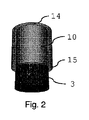
図1は、中空円筒の形態のハウジング10を備えるエアロゾル発生物品1を示す。ハウジングの内側に配置された要素を最もよく図示するために、ハウジング10は半透明で描かれている。円筒の形態のピストン11が、中空円筒ハウジングの中に部分的に(約半分まで)配置されている。ピストン11およびハウジング10は同一の長さを有し、ピストンはハウジングから突出している。ピストンの基部13の下方で、ハウジング10の中にくぼみ12が形成されている。くぼみ12はエアロゾル形成基体3(例えば、たばこ基体)で充填されている。使用時、例えば物品1がエアロゾル発生装置の中へと挿入された後、ピストン11がハウジング10の中へと押され、これによってエアロゾル形成基体3はくぼみ12から押し出され、かつハウジング10の開放基部端15から押し出され、これによって物品1から押し出される。この押し出された状態が図2に図示されており、ピストン11は、ハウジング10の上部端14と同一平面で配置されており、くぼみ12が完全に空であることを示している。
FIG. 1 shows an aerosol-generating
図3および図4は、中空円筒ハウジング10および円筒状のピストン11を示し、ピストン11はハウジング10の約半分の長さを有する。この場合もやはり、ハウジング10は半透明で描かれている。ピストン11は完全にハウジング10内に配置されており、ピストン11の上部15がハウジング10の上部端14と同一平面で配置されている。ピストンの基部の下方でくぼみ12が形成されており、これはエアロゾル形成基体3で充填されている。使用時、ピストン11はハウジングの中へとさらに押され(図3で矢印によって示されている)、これによって基体をくぼみ12から押し出す。押し出された状態が図4に図示されている。
3 and 4 show a hollow
ピストン11が基体3とともにハウジング10から部分的にまたは完全に押し出されるのを防止するために、ハウジング10内にエンドストップ(図示せず)が提供されてもよい。エンドストップはまた、ピストンの反対方向での動きを防止するまたは妨げるように、すなわち図3に示す通り、ピストン11が元の位置に戻るのを防止するまたは妨げるように提供される場合がある。
An end stop (not shown) may be provided within the
図5および図6は、円筒状の加熱チャンバー40および移動可能な基部41を有するヒーター4を示す。移動可能な基部は円筒状の加熱チャンバーピストン42の上部によって形成されており、これは加熱チャンバー壁43を形成する中空円筒内で移動可能である。加熱チャンバーピストン42には、ピストン42から半径方向外向きに突出するレバー44が提供されている。レバー44を起動することによって、加熱チャンバーピストン42は加熱チャンバーの中へと動いてもよく(図5で、動く方向は矢印によって示されている)、これによってヒーターの基部41はヒーターの上部に対して動く。これによって、エアロゾル形成基体は、例えば基体が使用された後、加熱チャンバー40から排出されてもよい。基部41は、例えばレバー44を反対方向に起動することによって、または基部を後ろ向き(図6では下向き)に押すことによって、その元の位置へと再度動かされてもよい。押す動作は、例えばエアロゾル形成基体がヒーター4の中へと押されることによって具体化される。
5 and 6 show a
図7〜図9は、エアロゾル発生装置の装置ハウジング60内に配置された、図1および図2の物品1と、図5および図6のヒーター4とを示す。装置ハウジング60の内側に配置された要素を最もよく図示するために、装置ハウジング60ならびに物品ハウジング10は半透明で描かれている。
7-9 show the
装置ハウジング60は基本的に中空円筒の形態を有し、また物品1およびヒーター4は装置ハウジング60に沿って内側に互いに隣り合って配置されている。加熱チャンバー壁43のリムによって形成されたヒーター4の上部は、挿入された物品1に対するエンドストップを形成する。図7は、ヒーター4の上方で装置ハウジング60内のくぼみの中へと挿入されている物品を示し、くぼみはエアロゾル形成物品1を受けるために提供されている。その後、物品1のピストン11は装置ハウジング60の中へとさらに押され、これによって物品ハウジング10の中へと押され、図8に図示するように、エアロゾル形成基体3を物品の基部端15からヒーター4の加熱チャンバーの中へと直接押し出す。物品ハウジングの外径および内径ならびにヒーターまたは加熱チャンバーの外径および内径はそれぞれ、相互に対応することが好ましく、その結果エアロゾル形成基体は、装置の長軸方向軸に沿ったピストン11の短い直線運動で物品からヒーター4の加熱チャンバー40の中へと完全に移動されてもよい。
The
装置ハウジング60は、ヒーター4のレバー44がハウジング60から側方に突出する長軸方向開口部61をハウジング壁内に備える。基体が使用された後、または再装填のために装置を準備するために、ヒーター4のレバー44は開口部61内で上向きに押されてもよい(矢印によって示されている)。ヒーターの基部41は上向きに押され、使用済みの基体を加熱チャンバーの外へ押し出し、物品の方向へと押す。基体は物品の中へと押し戻されてもよく、または図9に示す通り、基体3は少なくとも部分的に物品を装置ハウジング60の外へと押し出す。ここで、物品はつかまれて廃棄されてもよく、または再充填されてもよい。
The
ピストン11およびハウジング10には、ピストンの動きを所望の範囲に制限するための係止機構が提供されてもよい。例えば、係止機構はピストンがハウジングの外へと完全に押し出されるのを防止してもよい。
The
開口部61のサイズは、ヒーター4の基部41の反対方向(図7〜図9では上向きおよび下向き)の動きを防止するエンドストップを画定してもよい。使用済みのすべての基体を装置から取り除くために、例えば装置を上下逆さまにしてもよく、その結果基体は重力によって装置から取り除かれる。
The size of the
図10および図11は、エアロゾル発生物品の異なる実施形態の使用のために適合された、エアロゾル発生装置6の変形を示す。装置および物品は、概してロッド状であり、実質的に円形の断面を有する。
10 and 11 show variants of the
図10では、装置ハウジング60には、物品ハウジング12から突出するピストン11を有するエアロゾル発生物品1を受けるための円筒状のくぼみ62が提供されている。物品1はくぼみ62の中へと、ある程度まで挿入されており、その結果ピストンはハウジング60の近位端から突出する。装置ハウジング60は、例えば図5および図6に記述したもののようなヒーター(図示せず)を備える。
In FIG. 10, the
装置ハウジング63の遠位部分は、例えば電池などの電源、および装置の加熱を制御するための電子機器を備えてもよい。装置の遠位部分には、装置を起動する(例えば、加熱サイクルを開始する)ための起動ノブ65が提供されている。装置の起動の前に、物品の突出するピストン11は、物品ハウジングの中へと押され、その結果ピストン11、物品ハウジング14の上端部、および装置64の近位端は相互に同一平面にある。ピストンのこの動作によって基体は加熱チャンバーの中へと挿入され、装置は基体を加熱する準備が整う。
The distal portion of the
使用後、ヒーター4のレバー44は装置の近位端の方向へと動かされてもよい。物品は装置6の近位端から部分的に押し出され、その結果物品1はユーザーによってつかまれ、装置から完全に取り除かれてもよい。
After use, the
図10では物品のピストン11は物品ハウジングの中へと、例えばユーザーの指によって直接押し込まれるか、または図11に示す通り、例えばマウスピースによって押し込まれる。カウンターサンクピストンを有するエアロゾル発生物品に対しては、マウスピースまたは他の押圧要素が使用されることが好ましい。
In FIG. 10, the
図11では、エアロゾル発生物品1はカウンターサンクピストン11を備え、これはマウスピース66に提供された押圧要素660によって装置の中へと押される。装置ハウジング60のくぼみ62の中への物品1の挿入後、マウスピース66と装置ハウジング60が組み立てられてもよい。組立の際に、マウスピース66の押圧要素660は、ピストン11を物品ハウジングの中へと、ひいては基体を加熱チャンバーの中へとさらに押す。図11では、押圧要素666の直径はピストンの直径に対応する。押圧要素はまた、ピストンより小さい直径を有してもよい。押圧要素の長さは、エアロゾル形成基体が充填される物品内のくぼみの長さに対応することが好ましい。押圧要素660を物品ハウジングの中へと完全に挿入することによって、エアロゾル形成基体はくぼみ62の外へと完全に押し出され、ヒーターの中へと押される。
In FIG. 11, the aerosol-generating
レバー44の起動は、この場合も物品1をくぼみ62の外へと部分的に排出し、またマウスピース66を装置ハウジング60から分解する。
The activation of the
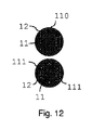
図12は、同軸に配置されたピストン11とハウジング12を有するエアロゾル発生物品の上面図を示す。図13では、物品1を通した加熱チャンバーから近位端までの装置の気流が、装置を通した長軸方向の断面図で示されている。
FIG. 12 shows a top view of an aerosol-generating article having a
気流はピストン11とハウジング12の間の界面に沿って提供されている。図12の上面図における物品の断面では、ピストン11およびハウジング12の直径は、ピストンとハウジングの間の細い円周方向に続く通路110を提供するように選ばれ、エアロゾルを含むまたは含まない気流が通路110を通過することを可能にする。図12の下の図における物品では、複数の規則正しく配置された別々の長軸方向チャネル111が界面に提供されている。
Airflow is provided along the interface between the
図13は、エアロゾル発生装置および気流管理の変形を概略的に示す。この場合もやはり、同一の参照番号が同一または類似の要素に使用されている。 FIG. 13 schematically shows a modification of the aerosol generator and airflow management. Again, the same reference number is used for the same or similar elements.
装置ハウジング60には、ハウジング壁内に、例えば加熱チャンバーの位置のわずかに上流に入口開口部68が提供されており、環境からの空気70が装置に入ることを可能する。空気70は、加熱チャンバーピストン42と加熱チャンバー壁43との間をヒーターの基部から加熱チャンバーの中へと、および加熱チャンバー内に配置された加熱されたエアロゾル形成基体3を通って通過する。そこでエアロゾルまたは蒸発した物質71は気流によって捕らえられ、またエアロゾルを含有する気流70、71は、物品1の通路110またはチャネル111を通過し、装置の近位端から出る。この近位端にはマウスピースが提供されてもよい。
The
図14および図15は、エアロゾル含有空気がエアロゾル発生物品の中央を通って通過する気流管理を図示する。 14 and 15 illustrate airflow management through which aerosol-containing air passes through the center of the aerosol-generating article.
物品のピストン11には、中央に配置されたチャネル112が提供されている。
The
図15の装置では、空気70はハウジング壁における開口部68を通って装置ハウジングに入る。開口部68は、ヒーターの上部の横に配置されている。空気70は、物品1の遠位端と加熱チャンバーの間で加熱チャンバーに入る。気流は物品1の中央のチャネル112を通して、蒸発した物質を搬送し、装置から出る。
In the device of FIG. 15, the
図16〜図18は、マウスピース66を備えるエアロゾル発生装置を図示する。マウスピース66は、中央に配置された出口開口部661を備え、ここでエアロゾル含有空気70、71はマウスピースを離れてもよく、またユーザーによって吸い込まれてもよい。図16の装置は図13の装置に対応し、ここでエアロゾル含有空気は物品の円形状に配置された界面に沿って下流に通過し、マウスピース66内で収集される。マウスピース66は中空であることが好ましい。マウスピースには、方向付け要素と、空気およびエアロゾルの混合を支援する混合要素とが提供されてもよい。装置ハウジングの遠位部分は、例えば電池600などの電源、および装置の加熱を制御するための電子機器601を備える。
16 to 18 illustrate an aerosol generator with a
図17では、マウスピース66と装置ハウジング60の近位端との間に一つまたはいくつかの入口開口部662が提供されている。前記入口開口部662を通して半径方向内向きに装置に入る空気70は、物品を通るチャネル111または通路110を通過し、加熱チャンバーおよび加熱チャンバー内に配置されたエアロゾル形成基体3の中へと入る。エアロゾル71が充満した気流は、物品内の中央に配置されたチャネル112およびマウスピースの出口開口部661を通って装置を離れる。
In FIG. 17, one or
図18は、図17に示された類似の気流管理を図示するが、物品は物品ハウジング12の長さよりも短い長さのピストンを有する。使用時、ピストン11は、押圧要素として機能するマウスピース66の延長部664で加熱チャンバーの方向へと押される。延長部664と物品ハウジング12の間に小さいチャネルが形成され、これを通してマウスピース66と装置ハウジング60の近位端との間に入る空気70は、ピストンとハウジングの間の界面へと通ってもよい。空気70は、物品を通るチャネル111または通路110を連続的に通って、加熱チャンバーおよび加熱チャンバー内に配置されたエアロゾル形成基体3の中へと入る。エアロゾル71が充満した気流は、物品内で中央に配置されたチャネル112を通して下流方向で物品を離れ、かつ延長部664を経由して、マウスピース66へと入る。マウスピースは中空であってもよく、またエアロゾル含有空気は出口開口部661を通してマウスピースを離れてもよい。
FIG. 18 illustrates similar airflow management shown in FIG. 17, but the article has a piston with a length shorter than the length of the
物品および装置ならびに気流管理の実施形態は単なる例証として示されている。異なる組み合わせおよび変形物もまた、本発明の範囲を逸脱することなく可能であり、例えば変形物および組み合わせは、加熱チャンバーの中への気流および加熱チャンバーを通る気流、またはエアロゾル発生物品の中への気流およびエアロゾル発生物品を通る気流に関連し、マウスピースを含むもしくは含まない装置、または押圧要素の配置および設計に関する。 Articles and devices and airflow management embodiments are shown merely as illustrations. Different combinations and combinations are also possible without departing from the scope of the invention, for example the variants and combinations into airflow into and through the heating chamber, or into aerosol-generating articles. In connection with airflow and airflow through aerosol-generating articles, the arrangement and design of a device containing or not including a mouthpiece, or a pressing element.
Claims (15)
前記くぼみおよび前記加熱チャンバーは、同一の長軸方向軸に沿って配置され、これによってエアロゾル形成基体は前記長軸方向軸の方向での直線運動で前記エアロゾル発生物品から前記加熱チャンバーの中へと移動可能であり、
前記システムが、前記装置の前記くぼみの中に少なくとも部分的に配置された請求項1〜4のいずれか一項に記載によるエアロゾル発生物品をさらに備える、エアロゾル発生システム。 An aerosol generation system comprising an aerosol generator, wherein the apparatus comprises a recess for receiving at least a portion of the aerosol generating article, the recess for the device to heat an aerosol forming substrate received from the aerosol generating article. Further equipped with a heating chamber located adjacent to
The recess and the heating chamber are arranged along the same major axis, whereby the aerosol-forming substrate moves linearly in the direction of the longitudinal axis from the aerosol-generating article into the heating chamber. Movable and
An aerosol generation system further comprising the aerosol generation article according to any one of claims 1 to 4, wherein the system is at least partially disposed in the recess of the apparatus.
エアロゾル形成基体を備えるエアロゾル発生物品の少なくとも一部分を受けるためのくぼみを備えるエアロゾル発生装置を備え、前記装置は前記エアロゾル発生物品から受けたエアロゾル形成基体を加熱するために前記くぼみに隣接して配置された加熱チャンバーをさらに備え、
開放端を有するハウジングを備えるエアロゾル発生物品を備え、前記ハウジングはエアロゾル形成基体を保持するためのくぼみを備え、前記くぼみの中に固体エアロゾル形成基体が提供され、前記物品は前記ハウジングの中で前記ハウジングの前記開放端の方向へと移動可能なピストンをさらに備え、
前記エアロゾル発生物品は前記エアロゾル発生装置の前記くぼみの中に少なくとも部分的に取り付けられるように構成されており、その結果前記固体エアロゾル形成基体は直線運動で前記エアロゾル発生物品から前記加熱チャンバーの中へと移動可能である、キット。 It is a kit for an aerosol generation system, and the kit is
An aerosol generator comprising a recess for receiving at least a portion of an aerosol-generating article comprising an aerosol-forming substrate is provided adjacent to the recess to heat the aerosol-forming substrate received from the aerosol-forming article. Further equipped with a heating chamber
An aerosol generating article comprising a housing having an open end, said housing comprising a recess for holding an aerosol forming substrate, a solid aerosol forming substrate being provided in the recess, said article in said housing. further comprising a piston movable into the direction of the open end direction of the housing,
The aerosol-generating article is configured to be at least partially mounted in the recess of the aerosol-generating device, so that the solid aerosol-forming substrate moves linearly from the aerosol-generating article into the heating chamber. And movable, kit.
Applications Claiming Priority (3)
| Application Number | Priority Date | Filing Date | Title |
|---|---|---|---|
| EP16171404 | 2016-05-25 | ||
| EP16171404.3 | 2016-05-25 | ||
| PCT/EP2017/062620 WO2017202959A2 (en) | 2016-05-25 | 2017-05-24 | Aerosol-generating article comprising a piston and aerosol-generating device |
Publications (3)
| Publication Number | Publication Date |
|---|---|
| JP2019519222A JP2019519222A (en) | 2019-07-11 |
| JP2019519222A5 JP2019519222A5 (en) | 2020-07-02 |
| JP6983816B2 true JP6983816B2 (en) | 2021-12-17 |
Family
ID=56098023
Family Applications (1)
| Application Number | Title | Priority Date | Filing Date |
|---|---|---|---|
| JP2018561040A Active JP6983816B2 (en) | 2016-05-25 | 2017-05-24 | Aerosol generators and aerosol generators with pistons |
Country Status (10)
| Country | Link |
|---|---|
| US (1) | US11197503B2 (en) |
| EP (1) | EP3462939B1 (en) |
| JP (1) | JP6983816B2 (en) |
| KR (1) | KR102525780B1 (en) |
| CN (1) | CN109195465A (en) |
| CA (1) | CA3025060A1 (en) |
| IL (1) | IL263125A (en) |
| MX (1) | MX2018014314A (en) |
| RU (1) | RU2745490C2 (en) |
| WO (1) | WO2017202959A2 (en) |
Families Citing this family (23)
| Publication number | Priority date | Publication date | Assignee | Title |
|---|---|---|---|---|
| CN106263039B (en) * | 2016-08-31 | 2018-12-28 | 云南中烟工业有限责任公司 | A kind of pressing nasal-suction type hot type cigarette smoking set |
| CN106263038B (en) * | 2016-08-31 | 2019-02-19 | 云南中烟工业有限责任公司 | A kind of push type air-jet device |
| WO2019175102A1 (en) * | 2018-03-13 | 2019-09-19 | Philip Morris Products S.A. | Cleaning tool for heating element using suction effect |
| EP3804546B1 (en) * | 2018-05-30 | 2022-10-19 | Shenzhen Yuyan Industrial Limited | Aerosol generating apparatus |
| US11723399B2 (en) | 2018-07-13 | 2023-08-15 | R.J. Reynolds Tobacco Company | Smoking article with detachable cartridge |
| CN109077356B (en) * | 2018-07-21 | 2024-04-16 | 深圳市你我网络科技有限公司 | Integrated electronic cigarette and processing method thereof |
| WO2020028591A1 (en) | 2018-07-31 | 2020-02-06 | Juul Labs, Inc. | Cartridge-based heat not burn vaporizer |
| KR102603413B1 (en) * | 2018-09-28 | 2023-11-17 | 필립모리스 프로덕츠 에스.에이. | Aerosol generating system with substrate advance |
| WO2020083852A1 (en) * | 2018-10-25 | 2020-04-30 | Jt International Sa | Dispenser and complementary vaporizer |
| EP3897238A1 (en) * | 2018-12-17 | 2021-10-27 | Philip Morris Products, S.A. | Aerosol generating article for use with an aerosol generating device |
| US11602164B2 (en) * | 2019-03-14 | 2023-03-14 | Rai Strategic Holdings, Inc. | Aerosol delivery device with graded porosity from inner to outer wall surfaces |
| EP3949770A4 (en) * | 2019-03-28 | 2022-11-16 | Japan Tobacco Inc. | Heating-type tobacco |
| US11330838B2 (en) | 2019-07-19 | 2022-05-17 | R. J. Reynolds Tobacco Company | Holder for aerosol delivery device with detachable cartridge |
| US11395510B2 (en) | 2019-07-19 | 2022-07-26 | R.J. Reynolds Tobacco Company | Aerosol delivery device with rotatable enclosure for cartridge |
| US11439185B2 (en) | 2020-04-29 | 2022-09-13 | R. J. Reynolds Tobacco Company | Aerosol delivery device with sliding and transversely rotating locking mechanism |
| US11589616B2 (en) | 2020-04-29 | 2023-02-28 | R.J. Reynolds Tobacco Company | Aerosol delivery device with sliding and axially rotating locking mechanism |
| EP4171280A1 (en) * | 2020-06-30 | 2023-05-03 | JT International SA | Aerosol generation apparatus to heat smokable material |
| US11825872B2 (en) | 2021-04-02 | 2023-11-28 | R.J. Reynolds Tobacco Company | Aerosol delivery device with protective sleeve |
| EP4333654A1 (en) * | 2021-05-04 | 2024-03-13 | Philip Morris Products S.A. | Aerosol-generating device with spanning stopper |
| EP4337041A1 (en) * | 2021-05-10 | 2024-03-20 | JT International S.A. | Aerosol generating device comprising a pushing bar |
| EP4337042A1 (en) * | 2021-05-10 | 2024-03-20 | JT International S.A. | Aerosol generating device comprising a cup-shaped heating chamber defining an open end and a sealed end |
| WO2023151959A1 (en) * | 2022-02-09 | 2023-08-17 | Jt International Sa | An aerosol generating device comprising a positioning mechanism |
| US20240065337A1 (en) * | 2022-08-30 | 2024-02-29 | R.J. Reynolds Tobacco Company | Aerosol delivery device with actuatable ignitor contacts and dual-purpose slider actuator |
Family Cites Families (23)
| Publication number | Priority date | Publication date | Assignee | Title |
|---|---|---|---|---|
| DE3227982A1 (en) | 1982-07-27 | 1984-02-09 | Dietrich Dipl.-Kfm. 6500 Mainz Lüdemann | Device for smoking tobacco |
| US5726421A (en) | 1991-03-11 | 1998-03-10 | Philip Morris Incorporated | Protective and cigarette ejection system for an electrical smoking system |
| US5240012A (en) | 1991-11-13 | 1993-08-31 | Philip Morris Incorporated | Carbon heat smoking article with reusable body |
| AR002035A1 (en) | 1995-04-20 | 1998-01-07 | Philip Morris Prod | A CIGARETTE, A CIGARETTE AND LIGHTER ADAPTED TO COOPERATE WITH THEMSELVES, A METHOD TO IMPROVE THE DELIVERY OF A SPRAY OF A CIGARETTE, A CONTINUOUS MATERIAL OF TOBACCO, A WORKING CIGARETTE, A MANUFACTURING MANUFACTURING METHOD , A METHOD FOR FORMING A HEATER AND AN ELECTRICAL SYSTEM FOR SMOKING |
| CN2257649Y (en) | 1996-04-18 | 1997-07-16 | 崔在国 | Hygienic cigarette holder |
| US6234167B1 (en) * | 1998-10-14 | 2001-05-22 | Chrysalis Technologies, Incorporated | Aerosol generator and methods of making and using an aerosol generator |
| US20090293892A1 (en) | 2008-05-30 | 2009-12-03 | Vapor For Life | Portable vaporizer for plant material |
| KR20120006994A (en) | 2009-03-05 | 2012-01-19 | 레드돗 비즈니스 솔루션즈 리미티드 | System and method for junket business |
| US9399110B2 (en) * | 2011-03-09 | 2016-07-26 | Chong Corporation | Medicant delivery system |
| KR20120006994U (en) * | 2011-04-01 | 2012-10-10 | 박정훈 | electronic cigaret cartridge |
| GB201109174D0 (en) | 2011-06-01 | 2011-07-13 | British American Tobacco Co | Smoking article |
| US20120325227A1 (en) | 2011-06-24 | 2012-12-27 | Alexander Robinson | Portable vaporizer |
| AR089648A1 (en) | 2011-08-16 | 2014-09-10 | Ploom Inc | LOW TEMPERATURE ELECTRONIC VAPORIZATION DEVICE AND METHODS |
| US9498588B2 (en) | 2011-12-14 | 2016-11-22 | Atmos Nation, LLC | Portable pen sized electric herb vaporizer with ceramic heating chamber |
| DK2800487T4 (en) * | 2012-01-03 | 2019-07-29 | Philip Morris Products Sa | Energy supply system for portable aerosol generating device |
| MX2015013513A (en) * | 2013-03-22 | 2016-10-26 | Altria Client Services Llc | Electronic smoking article. |
| GB2524856B (en) * | 2014-04-02 | 2021-04-07 | Twenty Sixteen 2016 Pharma Ltd | Pulmonary delivery devices |
| KR20220153098A (en) * | 2013-12-11 | 2022-11-17 | 제이티 인터내셔널 소시에떼 아노님 | Heating system and method of heating for an inhaler device |
| CN203723440U (en) | 2014-01-06 | 2014-07-23 | 深圳市聚思创科技有限公司 | Multipurpose electronic atomizer |
| CN103859605A (en) | 2014-02-21 | 2014-06-18 | 红云红河烟草(集团)有限责任公司 | Stepping uniform electric heating cigarette |
| SG11201606430QA (en) | 2014-04-30 | 2016-09-29 | Philip Morris Products Sa | A container having a heater for an aerosol-generating device, and aerosol-generating device |
| PL2944205T3 (en) | 2014-05-15 | 2019-10-31 | Fontem Holdings 1 Bv | Electronic smoking device and mouthpiece |
| CN104188107B (en) | 2014-07-30 | 2019-01-08 | 深圳市合元科技有限公司 | The baking-type smoking apparatus of controllable tobacco heating amount |
-
2017
- 2017-05-24 RU RU2018145530A patent/RU2745490C2/en active
- 2017-05-24 KR KR1020187036880A patent/KR102525780B1/en active IP Right Grant
- 2017-05-24 CA CA3025060A patent/CA3025060A1/en not_active Abandoned
- 2017-05-24 JP JP2018561040A patent/JP6983816B2/en active Active
- 2017-05-24 CN CN201780031884.9A patent/CN109195465A/en active Pending
- 2017-05-24 MX MX2018014314A patent/MX2018014314A/en unknown
- 2017-05-24 EP EP17726277.1A patent/EP3462939B1/en active Active
- 2017-05-24 US US16/302,178 patent/US11197503B2/en active Active
- 2017-05-24 WO PCT/EP2017/062620 patent/WO2017202959A2/en unknown
-
2018
- 2018-11-19 IL IL263125A patent/IL263125A/en unknown
Also Published As
| Publication number | Publication date |
|---|---|
| CN109195465A (en) | 2019-01-11 |
| EP3462939B1 (en) | 2021-05-19 |
| EP3462939A2 (en) | 2019-04-10 |
| KR20190008935A (en) | 2019-01-25 |
| RU2018145530A (en) | 2020-06-25 |
| IL263125A (en) | 2019-01-31 |
| WO2017202959A2 (en) | 2017-11-30 |
| WO2017202959A3 (en) | 2018-01-11 |
| US11197503B2 (en) | 2021-12-14 |
| RU2745490C2 (en) | 2021-03-25 |
| RU2018145530A3 (en) | 2020-09-25 |
| CA3025060A1 (en) | 2017-11-30 |
| KR102525780B1 (en) | 2023-04-27 |
| MX2018014314A (en) | 2019-02-25 |
| JP2019519222A (en) | 2019-07-11 |
| US20190274358A1 (en) | 2019-09-12 |
Similar Documents
| Publication | Publication Date | Title |
|---|---|---|
| JP6983816B2 (en) | Aerosol generators and aerosol generators with pistons | |
| KR102642688B1 (en) | Cartridges for aerosol-generating systems | |
| KR102523294B1 (en) | Aerosol-generating system comprising a heated aerosol-generating article | |
| US11076638B2 (en) | Electrically operated aerosol-generating system with multiplecomponent aerosol-generating article | |
| KR102592418B1 (en) | Refillable aerosol-generating articles and aerosol-generating kits and systems | |
| KR102459761B1 (en) | Heating non-combustible cigarette provided with a cavity-type container end | |
| US11116248B2 (en) | Electrically operated aerosol-generating system with tubular aerosol-generating article having improved airflow | |
| EA034534B1 (en) | Aerosol-generating device and capsule for use in an aerosol-generating device | |
| EP3843570A1 (en) | Aerosol-generating article with absorbent carrier | |
| KR102636268B1 (en) | Aerosol-generating device having a movably attached mouthpiece | |
| TW202021489A (en) | Vapour generating device | |
| JP2021530995A (en) | Articles for forming aerosols | |
| JP7472105B2 (en) | Aerosol-generating article with absorbent carrier | |
| KR20230088813A (en) | Aerosol-generating article having a capsule portion |
Legal Events
| Date | Code | Title | Description |
|---|---|---|---|
| A521 | Request for written amendment filed |
Free format text: JAPANESE INTERMEDIATE CODE: A523 Effective date: 20200522 |
|
| A621 | Written request for application examination |
Free format text: JAPANESE INTERMEDIATE CODE: A621 Effective date: 20200522 |
|
| A977 | Report on retrieval |
Free format text: JAPANESE INTERMEDIATE CODE: A971007 Effective date: 20210524 |
|
| A131 | Notification of reasons for refusal |
Free format text: JAPANESE INTERMEDIATE CODE: A131 Effective date: 20210531 |
|
| A521 | Request for written amendment filed |
Free format text: JAPANESE INTERMEDIATE CODE: A523 Effective date: 20210827 |
|
| TRDD | Decision of grant or rejection written | ||
| A01 | Written decision to grant a patent or to grant a registration (utility model) |
Free format text: JAPANESE INTERMEDIATE CODE: A01 Effective date: 20211025 |
|
| A61 | First payment of annual fees (during grant procedure) |
Free format text: JAPANESE INTERMEDIATE CODE: A61 Effective date: 20211124 |
|
| R150 | Certificate of patent or registration of utility model |
Ref document number: 6983816 Country of ref document: JP Free format text: JAPANESE INTERMEDIATE CODE: R150 |