JP6983334B2 - Image recognition device - Google Patents
Image recognition device Download PDFInfo
- Publication number
- JP6983334B2 JP6983334B2 JP2020546756A JP2020546756A JP6983334B2 JP 6983334 B2 JP6983334 B2 JP 6983334B2 JP 2020546756 A JP2020546756 A JP 2020546756A JP 2020546756 A JP2020546756 A JP 2020546756A JP 6983334 B2 JP6983334 B2 JP 6983334B2
- Authority
- JP
- Japan
- Prior art keywords
- dimensional object
- recognition
- image
- area
- recognition device
- Prior art date
- Legal status (The legal status is an assumption and is not a legal conclusion. Google has not performed a legal analysis and makes no representation as to the accuracy of the status listed.)
- Active
Links
Images


Classifications
-
- G—PHYSICS
- G06—COMPUTING; CALCULATING OR COUNTING
- G06T—IMAGE DATA PROCESSING OR GENERATION, IN GENERAL
- G06T7/00—Image analysis
Description
本発明は、画像認識装置に関する。 The present invention relates to an image recognition device.
近年、運転支援や自動運転等に必要な画像認識装置に対する性能向上への要求が高まっている。例えば、歩行者に対する衝突安全機能では、自動車アセスメントにおいて夜間歩行者への衝突安全試験が追加されるなど、性能向上が求められている。これを実現するために、歩行者など立体物に対する高い認識性能が必要になる。 In recent years, there has been an increasing demand for improved performance of image recognition devices required for driving support and automatic driving. For example, in the collision safety function for pedestrians, performance improvement is required, such as the addition of a collision safety test for night pedestrians in an automobile assessment. In order to achieve this, high recognition performance for three-dimensional objects such as pedestrians is required.
特許文献1には、ある移動立体物と他の立体物が重なっている状況において、立体物を内包する所定の領域の内部の特徴点を追跡することで領域の内部に存在する歩行者などの移動立体物を検知する認識装置が提案されている。 Patent Document 1 describes, in a situation where a moving three-dimensional object and another three-dimensional object overlap each other, a pedestrian or the like existing inside the region by tracking the feature points inside a predetermined region containing the three-dimensional object. A recognition device for detecting a moving three-dimensional object has been proposed.
しかしながら従来の装置では、立体物の全体をうまく検知できなかった場合に認識性能が低下するという課題があった。 However, the conventional device has a problem that the recognition performance is deteriorated when the entire three-dimensional object cannot be detected well.
本発明の第1の態様による画像認識装置は、撮像部によって撮像された画像上に設定された立体物の検知領域を、前記立体物の検知特性情報に基づいて前記画像上で拡大もしくは縮小することで、前記画像上に立体物領域を設定する立体物領域設定部と、前記立体物領域設定部により設定された前記立体物領域に対して前記立体物の種別を特定する認識処理を行う認識処理部と、を備える。
本発明の第2の態様による画像認識装置は、撮像部によって撮像された画像上に設定された立体物の検知領域を、前記立体物の第1の特性情報に基づいて前記画像上で拡大もしくは縮小することで、前記画像上に立体物領域を設定する立体物領域設定部と、前記立体物領域設定部によって求めた前記立体物領域を基準サイズとして、前記立体物の第2の特性情報に基づいて、複数のサイズの認識領域を定める認識倍率設定部と、前記認識倍率設定部で定めた複数の前記認識領域に対して、前記立体物の第3の特性情報に基づいて前記認識領域よりも広い複数の走査領域を設定する走査領域設定部と、前記走査領域設定部で設定された前記走査領域を用いて、前記立体物の種別を特定する認識処理を行う認識処理部と、を備える。
本発明の第3の態様による画像認識装置は、撮像部によって撮像された画像上に設定された立体物の検知領域に対して、前記立体物の検知特性情報に基づいて前記立体物の検知領域を拡大もしくは縮小して立体物領域を設定する立体物領域設定部と、前記立体物領域設定部により設定された前記立体物領域に対して前記立体物の種別を特定する認識処理を行う認識処理部と、前記立体物領域設定部によって求めた前記立体物領域を基準サイズとして、前記立体物の認識特性情報に基づいて、複数のサイズの認識領域を定める認識倍率設定部と、を備え、前記認識処理部は、前記認識倍率設定部で定められた複数のサイズの前記認識領域に対して、それぞれに前記認識処理を行う。
Image recognition apparatus according to the first aspect of the present invention, the detection area of the three-dimensional object that has been set on the captured image by the imaging unit, and enlarged or reduced on the image based on the detection characteristics information of said three-dimensional object This recognizes the three-dimensional object area setting unit that sets the three-dimensional object area on the image and the recognition process that specifies the type of the three-dimensional object for the three-dimensional object area set by the three-dimensional object area setting unit. It is equipped with a processing unit.
Image recognition device according to the second aspect of the present invention, or a larger detection area of the three-dimensional object that has been set on the captured image by the imaging unit on the first on the basis of the characteristic information image of the three-dimensional object By reducing the size, the third characteristic information of the three-dimensional object is based on the three-dimensional object area setting unit that sets the three-dimensional object region on the image and the three-dimensional object region obtained by the three-dimensional object region setting unit as a reference size. Based on the recognition magnification setting unit that defines recognition regions of a plurality of sizes, and the recognition regions defined by the recognition magnification setting unit, from the recognition region based on the third characteristic information of the three-dimensional object. It also includes a scanning area setting unit that sets a plurality of wide scanning areas, and a recognition processing unit that performs recognition processing for specifying the type of the three-dimensional object using the scanning area set by the scanning area setting unit. ..
The image recognition device according to the third aspect of the present invention has the detection area of the three-dimensional object set on the image captured by the imaging unit based on the detection characteristic information of the three-dimensional object. A recognition process that specifies the type of the three-dimensional object for the three-dimensional object area set by the three-dimensional object area setting unit and the three-dimensional object area setting unit that sets the three-dimensional object area by enlarging or reducing the A unit and a recognition magnification setting unit that defines recognition areas of a plurality of sizes based on the recognition characteristic information of the three-dimensional object, with the three-dimensional object area obtained by the three-dimensional object area setting unit as a reference size, are provided. The recognition processing unit performs the recognition processing on each of the recognition areas of a plurality of sizes defined by the recognition magnification setting unit.
本発明によれば、立体物を的確に検知し、認識性能を向上させた画像認識装置を提供できる。 According to the present invention, it is possible to provide an image recognition device that accurately detects a three-dimensional object and has improved recognition performance.
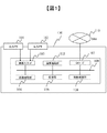
図1は、本実施形態にかかわる画像認識装置100の全体構成を示すブロック図である。画像認識装置100は、車両に搭載され、車両前方の左右に配置された左カメラ101と右カメラ102を備える。カメラ101、102は、ステレオカメラを構成し、例えば、歩行者、車両、信号、標識、白線、車のテールランプ、ヘッドライトなどの立体物を撮像する。画像認識装置100は、カメラ101、102で撮像された車両前方の画像情報に基づいて車外環境を認識する。そして、車両(自車両)は、画像認識装置100による認識結果に基づいて、ブレーキ、ステアリングなどを制御する。
FIG. 1 is a block diagram showing an overall configuration of an
画像認識装置100は、カメラ101、102で撮像した画像を画像入力インタフェース103より取り込む。画像入力インタフェース103より取り込まれた画像情報は、内部バス109を介して画像処理部104へ送られる。そして、演算処理部105で処理され、処理途中の結果や最終結果の画像情報などは記憶部106に記憶される。
The
画像処理部104は、左カメラ101の撮像素子から得られる第1の画像と、右カメラ102の撮像素子から得られる第2の画像とを比較して、それぞれの画像に対して、撮像素子に起因するデバイス固有の偏差の補正や、ノイズ補間などの画像補正を行い、これを記憶部106に記憶する。更に、第1の画像と第2の画像との間で、相互に対応する箇所を計算して、視差情報を求め、画像上の各画素に対応する距離情報として、これを記憶部106に記憶する。画像処理部104は、内部バス109を介して演算処理部105、CANインタフェース107、制御処理部108に接続されている。
The
演算処理部105は、記憶部106に蓄えられた画像情報および距離情報(視差情報)を使い、車両周辺の環境を把握するために、立体物の認識を行う。立体物の認識結果や中間的な処理結果の一部が、記憶部106に記憶される。演算処理部105は、撮像した画像に対して立体物の認識を行った後に、認識結果を用いて車両制御の計算を行う。車両制御の計算の結果として得られた車両の制御方針や、認識結果の一部はCANインタフェース107を介して、車載ネットワークCAN110に伝えられ、これにより車両の制御が行われる。
The
制御処理部108は、各処理部が異常動作を起こしていないか、データ転送時にエラーが発生していないかなどを監視し、異常動作を防止する。画像処理部104、演算処理部105、および制御処理部108は、単一または複数のコンピュータユニットにより構成してもよい。
The
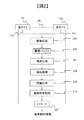
図2は、画像認識装置100の動作を示すフローチャートである。
画像認識装置100に備えられた左カメラ101と右カメラ102とにより画像が撮像され、撮像された画像情報203、204のそれぞれについて、撮像素子が持つ固有の癖を吸収するための補正などの画像処理205を行う。画像処理205の処理結果は画像バッファ206に蓄えられる。画像バッファ206は、図1の記憶部106に設けられる。FIG. 2 is a flowchart showing the operation of the
An image is captured by the
次に視差処理207が行われる。具体的には、補正された2つの画像を使って、画像同士の照合を行い、これにより左カメラ101、右カメラ102で得た画像の視差情報を得る。左右画像の視差により、立体物の画像上のある着目点が、三角測量の原理によって、立体物までの距離として求められる。画像処理205および視差処理207は、図1の画像処理部104で行われ、最終的に得られた画像情報、および視差情報は記憶部106に蓄えられる。
Next, the
そして、次の検知処理208では、視差処理207により左右画像の各画素の視差または距離が得られた視差情報を用いて、3次元空間上の立体物を検知する。図3は、検知処理208により画像上に設定された立体物の検知領域を示す図である。図3には、検知処理208の結果、画像上において、カメラ101、102によって検知された歩行者の検知領域301と車両の検知領域302が示されている。これらの検知領域301、302は、図3に示すように矩形であっても、視差や距離から得られる不定形の領域であってもよい。後段の処理において計算機での扱いを容易にするため一般的には矩形として扱われる。本実施形態では以下、領域は矩形として扱い、立体物の一例として主に歩行者を用いて説明する。
Then, in the
次に、認識処理209では、検知処理208により画像上に設定された検知領域に対して立体物の種別を特定する認識処理を行う。認識処理209による認識対象の立体物は、例えば、歩行者、車両、信号、標識、白線、車のテールランプやヘッドライトなどであり、これらの何れであるかその種別が特定される。この認識処理209が安定して立体物の認識を行うためには、画像上の検知領域と認識したい対象の領域が一致している必要がある。しかし、カメラ101、102においては外環境の明るさやカメラ間の撮像性能のばらつきなどによって、認識したい画像上の領域を完全に一致させることができない場合がある。これは、ミリ波などのレーダーと、カメラなどの画像センサを組み合わせた場合でも同様である。この問題を解決した認識処理209の詳細については後述する。
Next, in the
次に、車両制御処理210では、立体物の認識結果と、自車両の状態(速度、舵角など)とを勘案して、例えば、乗員に警告を発し、自車両のブレーキングや舵角調整などの制御を行う。あるいは、認識した立体物に対する回避制御を定め、その結果を自動制御情報としてCANインタフェース107を介して出力する。認識処理209および車両制御処理210は、図1の演算処理部105で行われる。
Next, in the
なお、図2のフローチャート、および後述の図4のフローチャートで示したプログラムを、CPU、メモリなどを備えたコンピュータにより実行することができる。全部の処理、または一部の処理をハードロジック回路により実現してもよい。更に、このプログラムは、予め画像認識装置100の記憶媒体に格納して提供することができる。あるいは、独立した記憶媒体にプログラムを格納して提供したり、ネットワーク回線によりプログラムを画像認識装置100の記憶媒体に記録して格納することもできる。データ信号(搬送波)などの種々の形態のコンピュータ読み込み可能なコンピュータプログラム製品として供給してもよい。
The program shown in the flowchart of FIG. 2 and the flowchart of FIG. 4 described later can be executed by a computer equipped with a CPU, a memory, and the like. All processing or some processing may be realized by a hard logic circuit. Further, this program can be previously stored and provided in the storage medium of the
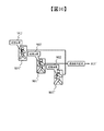
図4は、認識処理209の詳細を示すフローチャートである。このフローチャートは、図4に示すように、立体物領域設定処理401、認識倍率設定処理402、走査領域設定処理403、倍率毎走査認識処理404、最適倍率設定処理406、詳細認識位置決定処理407、詳細認識処理408を行う。以下、順に各処理を説明する。なお、これらの処理ではステレオカメラを前提に説明する。
FIG. 4 is a flowchart showing the details of the
[立体物領域設定処理]
立体物領域設定処理401では、検知処理208によって得られた立体物の検知領域301を、立体物の検知特性情報に基づいて拡大もしくは縮小して立体物領域501を設定する。[Three-dimensional object area setting process]
In the three-dimensional object
図5は、立体物領域設定処理401の原理を説明する図である。図5では、歩行者の検知領域301を立体物の検知特性情報に基づいて拡大して立体物領域501を設定した例を示す。検知特性情報は、例えば、(1)立体物の識別性、(2)立体物との距離、(3)立体物の大きさ、(4)立体物の想定サイズ、(5)外環境の明るさ、(6)ヘッドライトの向き、(7)立体物が存在する路面の高さ、(8)センサ分解能などである。以下に、これらの検知特性情報について説明する。
FIG. 5 is a diagram illustrating the principle of the three-dimensional object
(1)立体物の識別性は、例えばカメラ101、102においては背景領域との組み合わせによって立体物が得にくい場合が考えられる。路面と同色の歩行者の服装や、夜間の歩行者の頭頂部などがこれに当たる。また、カメラ101、102が雨滴などの影響で対象の一部がぼけて立体物領域が欠けることも考えられる。このような場合、検知領域を拡大する。また、三次元空間中の人と人以外の領域が結合した立体物になる場合も有る。路肩の電柱や柵などと言った立体物と人との結合のように識別前に分離することは困難なためである。このような場合に画像の色や輝度やエッジに基づいて検知領域を縮小する。また、レーダーセンサなどの別種のセンサや、カメラ101、102においても水平方向の取り付け高さが違う場合、主に上部方向に隠れが発生し、立体物は小さく出る。このような構成の処理特性を持つ場合には検知領域を拡大する。
(1) As for the distinctiveness of a three-dimensional object, for example, in
(2)立体物との距離は、遠ければ大きく立体物領域を拡大し、近ければ小さく立体物領域を縮小する。この拡大率は、カメラ101、102を含むセンサ分解能によって決定しても良い。対象が遠方に行けば行くほど1画素あたりの3次元空間を占めるサイズが大きくなり、誤差が乗るからである。
(2) As for the distance to the three-dimensional object, if it is far, the three-dimensional object area is greatly expanded, and if it is close, the three-dimensional object area is reduced. This magnification may be determined by the sensor resolution including the
(3)立体物の大きさは、立体物が小さければ立体物領域を拡大し、立体物が大きければ立体物領域を縮小する。 (3) As for the size of the three-dimensional object, if the three-dimensional object is small, the three-dimensional object area is expanded, and if the three-dimensional object is large, the three-dimensional object area is reduced.
(4)立体物の想定サイズは、例えば、立体物を歩行者と想定して、歩行者と想定して小さ過ぎる立体物は立体物領域を拡大し、歩行者と想定して大き過ぎる立体物は立体物領域を縮小する。どの程度のものまでを対象とするかは、(5)外環境の明るさや(6)ヘッドライトの向きも考慮に入れて決定してよい。例えば、昼の明るい環境であれば立体物領域を縮小し、夜の暗い環境であれば立体物領域を拡大する。また、ヘッドライトの向きに応じて、例えば、ヘッドライトの向きがロウビームであれば足元に光が当たっているので、高さ方向に立体物領域を拡大する。ヘッドライトの向きがハイビームであれば、全身に光が当たっているので立体物領域を縮小する。また、立体物までの距離や(7)立体物が存在する位置の路面の高さによっても立体物領域を拡大もしくは縮小してもよい。例えば、路面の高さが低い場合に、ハイビームであれば、足元には光が当たらないため下方向に立体物領域を拡大する。 (4) The assumed size of a three-dimensional object is, for example, assuming that the three-dimensional object is a pedestrian, and the three-dimensional object that is too small assuming that it is a pedestrian expands the three-dimensional object area and is too large assuming that it is a pedestrian. Reduces the three-dimensional object area. The extent to which the target is targeted may be determined in consideration of (5) the brightness of the external environment and (6) the direction of the headlights. For example, in a bright environment in the daytime, the three-dimensional object area is reduced, and in a dark environment at night, the three-dimensional object area is expanded. Further, depending on the direction of the headlight, for example, if the direction of the headlight is a low beam, the light hits the feet, so that the three-dimensional object region is expanded in the height direction. If the direction of the headlight is high beam, the whole body is exposed to light, so the three-dimensional object area is reduced. Further, the three-dimensional object region may be expanded or reduced depending on the distance to the three-dimensional object and (7) the height of the road surface at the position where the three-dimensional object exists. For example, when the height of the road surface is low, if the high beam is used, the light does not hit the feet, so the three-dimensional object area is expanded downward.
(8)センサ分解能は、センサがカメラ101、102であれば、距離に応じて1画素あたりのサイズが変わるので、立体物のサイズや、対象の距離と組み合わせることによって立体物領域を拡大もしくは縮小する。例えば、立体物が近傍に居る場合は1画素あたりの3次元空間の分解能が高いため、立体物領域を拡大する。立体物が遠い場合は1画素あたりの3次元空間の分解能が低いため、立体物領域を縮小する。また、立体物領域として取得する領域の特性によっては、立体物領域を縮小する。立体物領域として取得する領域の特性とは、例えば立体物領域が得られた視差のある領域やセンサ応答領域がより大きく設定される場合であり、このような場合は立体物領域を縮小する。
(8) If the sensor is a
立体物の検知特性情報に基づいて立体物領域501を設定する例について説明する。例えば、歩行者においては、画像上の変化が大きい手足領域は欠けて小さくなりやすい。また、夜間の場合は黒髪の人ならば、頭が背景と混ざって検知しづらい。このような場合に、1画素あたりの3次元空間上のサイズを元にして、画像上の立体物領域501を変更する。例えば、明るい昼間なら頭部と思われる領域の拡大は0cm、足元の領域の拡大は10cm、夜間なら頭部の領域の拡大は10cm、足元の領域の拡大は10cmとする。さらに車両のロウビームが届く範囲なら頭部の領域の拡大は10cm、足元の領域の拡大は0cmとする。横幅も同様に適宜拡大縮小する。また時系列による横幅の変化量を元に補正を実施しても良い。また、後段の認識処理の内容によっては、認識領域を縮小しても良い。例えば、歩行者であれば上半身のみで認識を実施する場合などである。拡大縮小するサイズは所定の割合、若しくは画像上のサイズで決定しても良いが、3次元空間上のサイズを基準に設定することにより、認識対象としてあり得ないサイズの除外が可能となる。
また、この拡大縮小による立体物領域501のサイズは、3次元空間上の距離と画素の関係から、検知領域301と同一になる場合もある。An example of setting the three-
Further, the size of the three-
以上、検知特性情報について説明したが、立体物領域設定処理401においては、これらの検知特性情報を複数組み合わせることによって、より精度よく立体物領域501を設定する。例えば、距離、外環境の明るさ、ライト向き、路面高さ、センサ分解能などを組み合わせることで、昼夜の影響をより軽減した立体物領域501を設定する。また、ここで述べた画素数やサイズは一例であり、この範囲に限定するものではない。
Although the detection characteristic information has been described above, in the three-dimensional object
[認識倍率設定処理]
次に、図4に示す認識倍率設定処理402について説明する。
立体物領域設定処理401で設定された立体物領域501を認識処理209の基準サイズとすると、この基準サイズが認識のための最適な認識領域とは限らない。そこで、認識倍率設定処理402では、立体物の認識特性情報を用いて複数のサイズの認識領域を定める。この時、最適な認識領域は不明であることから、基準サイズを元に認識領域を拡大もしくは縮小して、複数のサイズの認識領域を定める。認識特性情報は、例えば、(1)立体物との距離、(2)立体物の大きさ、(3)立体物の限界サイズ、(4)センサ分解能などである。以下に、これらの認識特性情報について説明する。[Recognition magnification setting process]
Next, the recognition
Assuming that the three-
(1)立体物との距離は、認識領域を拡大もしくは縮小を行う場合の拡大量もしくは縮小量を決定する指標となる。例えば、立体物が遠方にある場合、1画素あたりの立体物サイズは大きくなる。この場合、認識処理を行う後述の識別器901の入力になるのは画像であるため、立体物が遠方にある場合は、近傍にある場合に比べて拡大もしくは縮小する画素数は小さくなる。そこで、基準サイズを元に、立体物との距離に応じて、認識領域を拡大もしくは縮小して、複数のサイズの認識領域を定める。
(1) The distance to the three-dimensional object is an index for determining the amount of enlargement or reduction when the recognition area is expanded or reduced. For example, when the three-dimensional object is far away, the size of the three-dimensional object per pixel becomes large. In this case, since the input of the
(2)立体物の大きさは、認識領域を拡大もしくは縮小を行う場合の拡大量もしくは縮小量を決定する指標となる。例えば、立体物が大きい場合は立体物が小さい場合に比べて、画像上で拡大もしくは縮小を行う場合の画素数は小さくなる。また、実空間上のサイズに基づいて複数のサイズの認識領域を定める場合、遠方に居る場合は近傍に居る場合に比べて、画像上で拡大もしくは縮小を行う場合の画素数は小さくなる。サブピクセル単位で認識領域を設定しない場合は、基準サイズと同じになる場合も有る。 (2) The size of a three-dimensional object is an index for determining the amount of enlargement or reduction when the recognition area is enlarged or reduced. For example, when the three-dimensional object is large, the number of pixels when enlarging or reducing the image is smaller than when the three-dimensional object is small. Further, when the recognition areas of a plurality of sizes are determined based on the sizes in the real space, the number of pixels when enlarging or reducing the image is smaller when the area is far away than when the area is near the area. If the recognition area is not set for each sub-pixel, it may be the same as the standard size.
(3)立体物の限界サイズは、立体物が認識対象である場合に想定される限界サイズである。例えば、立体物が歩行者である場合、立体物の高さが2.5メートルを超えるなど大きければ、縮小方向に領域を設定する。逆に高さが0.8メートルを下回るなど小さければ、拡大方向に領域を設定する。それら中間であれば、双方に領域を設定する。設定する領域の上限下限は、認識対象の立体物や認識処理の制限などから決定してよい。 (3) The limit size of a three-dimensional object is a limit size assumed when the three-dimensional object is a recognition target. For example, when the three-dimensional object is a pedestrian, if the height of the three-dimensional object is large, such as exceeding 2.5 meters, the area is set in the reduction direction. On the contrary, if the height is small, such as less than 0.8 meters, the area is set in the expansion direction. If it is in the middle, set the area on both sides. The upper and lower limits of the area to be set may be determined from the three-dimensional object to be recognized, the limitation of the recognition process, and the like.
(4)センサ分解能は、例えばセンサがカメラ101、102であれば、距離に応じて1画素あたりのサイズが変わる。そこで、センサ分解能を基に拡大もしくは縮小する範囲を定めることができる。例えば1画素あたりの3次元空間中のサイズが20cmを超すような遠方においては、拡大もしくは縮小する範囲は1画素、2画素と言った小さな範囲で定める。逆に1画素あたりの3次元空間中のサイズが1cmを切るような近距離においては、10画素や20画素と言った大きな範囲で拡大もしくは縮小する。
(4) As for the sensor resolution, for example, if the sensors are
なお、画像上のサイズは3次元空間中の立体物サイズから逆算して求めても良い。また、立体物領域設定処理401において立体物領域501の設定に考慮しなかった検知特性情報に関しては、認識倍率設定処理402で検知特性情報を用いて認識領域のバリエーションを設定してもよい。その場合、検知特性情報のどの条件に応じて認識領域を拡大するか縮小するかは、立体物領域設定処理401で説明した内容と同様である。また、ここで述べた画素数やサイズは一例であり、この範囲に限定するものではない。
The size on the image may be obtained by back calculation from the size of a three-dimensional object in the three-dimensional space. Further, regarding the detection characteristic information that is not considered in the setting of the three-
図6は認識倍率設定処理402の原理を説明する図である。認識倍率設定処理402は、立体物領域501を基準サイズの認識領域として、これを拡大もしくは縮小した認識領域601、602を定める。認識領域501は基準サイズ、認識領域601は、基準サイズを縮小した認識倍率の小さい認識領域、認識領域602は、基準サイズを拡大した認識倍率の大きい認識領域である。図6の例では基準サイズに対して拡大もしくは縮小した2種類の認識領域を示したが、この数は認識処理時間に余裕があれば多数のバリエーションを持ってよい。また、検知処理208や立体物領域設定処理401の設定により、拡大と縮小どちらかのみを設定してもよい。認識領域の拡大量もしくは縮小量は、認識特性情報に基づいて設定する。この場合、立体物領域設定処理401と同様に、画像の分解能によっては基準サイズの認識領域と同一となる場合もある。
FIG. 6 is a diagram illustrating the principle of the recognition
図7は、認識倍率設定処理402における正規化を説明する図である。
図7に示すように、認識領域(501、601、602)を後段の認識処理を実施する場合において正規化する領域を定めている。認識領域は、後述の認識処理において、認識処理を行う範囲を示すものである。認識領域501は基準サイズ、認識領域601は、基準サイズを縮小した認識倍率の小さい認識領域、認識領域602は、基準サイズを拡大した認識倍率の大きい認識領域である。FIG. 7 is a diagram illustrating normalization in the recognition
As shown in FIG. 7, the area for normalizing the recognition area (501, 601 and 602) when the recognition process in the subsequent stage is performed is defined. The recognition area indicates a range in which the recognition process is performed in the recognition process described later. The
認識処理においては入力情報の次元数を合わせる必要がある。基準サイズの認識領域501は対象の物体を綺麗に捉えている保証が無く、また装置に実装された認識処理の特性によって、どのように捉えていればよいかが変わってくる。そこで、正規化する領域をあらかじめ設定する。図7の例では、認識領域501は頭と足がほぼ入っているのに対し、認識倍率の小さい認識領域601は頭頂部と手足がはみ出でおり、認識倍率の大きい認識領域602は逆に頭頂部や足元に余白ができる。これらの認識領域を同じサイズに正規化すると、図7に示すように、正規化後の認識領域701、702、703となり、後述の認識処理で同様な処理を施すことが可能となる。ただしこの正規化処理は認識倍率設定処理402で必ずしも行うものではない。後述の倍率毎走査認識処理404や後述の詳細認識処理408の処理の一部として実施してよい。
In the recognition process, it is necessary to match the number of dimensions of the input information. There is no guarantee that the
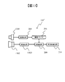
[走査領域設定処理]
次に、図4の走査領域設定処理403について説明する。走査領域設定処理403は、各認識領域に対して、立体物の配置特性情報に基づいて、認識領域よりも大きな走査領域を設定する。走査領域は画像上の領域として設定され、認識処理においては、設定された走査領域内を認識領域により走査する。すなわち、認識領域は、後述の認識処理において、認識処理を行う範囲を示すものであり、走査領域は、この認識領域を走査領域の範囲内において移動させる範囲である。これにより、認識領域を走査領域の範囲内において移動させながら認識処理を行う。走査領域の大きさを決定する配置特性情報は、例えば、(1)立体物の遠近位置、(2)立体物が存在する路面高さなどである。以下に、これらの配置特性情報について説明する。[Scanning area setting process]
Next, the scanning
(1)立体物の遠近位置は、走査領域の設定を行う場合の指標となる。例えば、立体物が近くに在る場合は、画像上の走査領域は大きく定める。また、立体物が遠方に在る場合は、走査領域は小さく定める。これは、近くに在る場合は、センサ分解能が高く、1画素走査した場合の3次元空間上の走査量が数mm程度になるのに対し、遠方では10cmを超える為である。走査領域は、立体物検知によって発生する検知のズレ量などの特性によっても定まる。例えば、立体物の横位置中心をとった場合に最も性能を発揮する認識処理を用いる場合、立体物の横位置中心と、実際の認識対象の横位置中心のズレ量や分散から、走査領域に認識対象の横位置中心が収まるように設定してもよい。 (1) The perspective position of a three-dimensional object is an index when setting the scanning area. For example, when a three-dimensional object is nearby, the scanning area on the image is largely defined. If the three-dimensional object is far away, the scanning area is set small. This is because the sensor resolution is high when the sensor is near, and the scanning amount in the three-dimensional space when scanning one pixel is about several mm, whereas when it is far away, it exceeds 10 cm. The scanning area is also determined by the characteristics such as the amount of deviation of detection generated by the detection of a three-dimensional object. For example, when the recognition process that exerts the best performance when the horizontal position center of the three-dimensional object is used, the deviation amount and dispersion between the horizontal position center of the three-dimensional object and the horizontal position center of the actual recognition target are taken into consideration in the scanning area. It may be set so that the center of the horizontal position of the recognition target fits.
(2)立体物が存在する路面高さは、走査領域の設定を行う場合の指標となる。例えば、路面が上昇しており立体物(歩行者など)が自車よりも高い位置に在る場合は、頭側の隠れが増えて高さが実際より小さく出る。また、立体物(歩行者など)が低い位置に在る場合は、画角などによっては足元が切れる、バンパーで隠れるなどが考えられる。このような状態に合わせて、走査領域を拡大もしくは縮小する。 (2) The height of the road surface where the three-dimensional object exists is an index when setting the scanning area. For example, when the road surface is raised and a three-dimensional object (pedestrian, etc.) is at a higher position than the own vehicle, the hiding on the head side increases and the height becomes smaller than the actual height. In addition, when a three-dimensional object (pedestrian, etc.) is in a low position, it is possible that the feet may be cut off or hidden by a bumper depending on the angle of view. The scanning area is enlarged or reduced according to such a state.
また、立体物領域設定処理401、認識倍率設定処理402において立体物領域や認識領域の設定に考慮しなかった検知特性情報や認識特性情報に関しては、これを用いて走査領域設定処理403で走査領域を定めてもよい。この場合、どの条件に応じて走査領域を拡大するか縮小するかは、立体物領域設定処理401や認識倍率設定処理402と同様である。また、ここで述べた画素数やサイズは一例であり、この範囲に限定するものではない。
Further, regarding the detection characteristic information and the recognition characteristic information that are not considered in the setting of the three-dimensional object area and the recognition area in the three-dimensional object
図8は、走査領域設定処理403の原理を説明する図である。走査領域設定処理403は、各認識領域501、601、602に対して、走査領域801、802、803をそれぞれ定める。走査領域801、802、803は認識領域501、601、602と同じかそれよりも大きな領域である。ただし走査領域801、802、803内を認識領域501、601、602で走査するため、走査量が多いとは限らない。走査領域801、802、803は配置特性情報から画像上の領域を定める。この時、画像の分解能によっては認識領域と走査領域の画像上が同じになる場合も有る。走査領域は、各認識領域に対して個別で定めるが、処理時間に余裕があるならば、最も走査領域が大きくなる1つを採用しても良い。また、処理時間に余裕ない場合、小さな走査領域1つを各認識領域に適応しても良い。
FIG. 8 is a diagram illustrating the principle of the scanning
[倍率毎走査認識処理]
次に、図4に示す倍率毎走査認識処理404について説明する。倍率毎走査認識処理404では、走査領域801、802、803に対応する画像および視差領域(距離領域)を認識領域501、601、602で走査し、各サイズの走査位置毎に認識処理を実施して、対象の走査位置が立体物であるかを判別する。[Scanning recognition process for each magnification]
Next, the
ここで、認識処理の性能が十分であるならば、図4の破線405に示すように、倍率毎走査認識処理404の結果を用いて車両制御処理210を実施してもよい。倍率毎走査認識処理404は倍率、走査位置などにより複数の結果を有する場合があるが、これは認識結果が最良であった1つを選択するなどの処理によって絞り込みを実施する。
Here, if the performance of the recognition process is sufficient, the
図9は倍率毎走査認識処理404の原理を説明する図である。各走査領域801、802、803内を、認識領域501、601、602で走査しながら、認識処理を行う識別器901で認識した結果の応答位置902を求める。応答位置902を図9ではxで示した。応答位置902の数が多いほど認識処理が良好であることを示している。走査領域801、802、803内を識別器901で認識した結果の一例は、走査領域801’、802’、803’の応答位置902で示すように、走査領域801’が最も多くなっている。
FIG. 9 is a diagram illustrating the principle of the
識別器901は機械学習を用いても良いし、ヒューリスティックな閾値判定を用いても良い。この判定結果が十分であるならば、図4の破線405に示したように、この結果を用いて認識を終えてよい。その場合、例えば最も認識処理が良好であったものを採用する。
The
倍率毎走査認識処理404において、認識処理の計算コストの削減などにより、認識処理の性能が不十分である場合に、倍率毎走査認識処理404の結果を用いて、詳細処理を実施してもよい。本実施形態においては詳細処理として、最適倍率設定処理406、詳細認識位置決定処理407、詳細認識処理408を設けた場合を説明する。
In the magnification per
[最適倍率設定処理]
図4に示す最適倍率設定処理406は、認識倍率設定処理402で作成した複数のサイズの認識領域から、詳細認識処理に最適な認識領域を選択する。選択方法は、例えば走査によって得られた認識処理結果における認識対象と判定された個数やその信頼度や、非認識対象と判定された個数やその信頼度、認識結果の分布などを用い、応答数の量や信頼度を複数のサイズの認識領域間で比較し、最適な認識領域を用いる。最適倍率設定処理406は、処理時間に十分な猶予がないならば省略してもよい。[Optimal magnification setting process]
The optimum
図10は最適倍率設定処理406の原理を説明する図である。複数の倍率の認識結果から、最も応答が良かった最適倍率を選択する。最適倍率は前述の通り、認識処理の走査領域での応答数やその信頼度を用いて選択する。図10の例では応答数が最も多かった走査領域801’を選択しているが、この走査領域801’は、基準サイズの走査領域801に対応し、基準サイズの走査領域801は基準サイズの認識領域501に対応している。
FIG. 10 is a diagram illustrating the principle of the optimum
[詳細認識位置決定処理]
図4に示す詳細認識位置決定処理407は、最適倍率設定処理406で得られた最適倍率について、詳細認識を実施する代表位置を決定する。詳細認識は、例えば、倍率毎走査認識処理404で得られた認識処理の信頼度が最大の位置を選ぶ。または、平均変位法(Mean Shift法)のようなクラスタリング手段を用いて位置を決定しても良い。最適倍率設定処理406を行わない場合、各倍率に対して詳細認識位置決定処理407を実施してよい。[Detailed recognition position determination process]
The detailed recognition
図11は詳細認識位置決定処理407の原理を説明する図である。倍率毎走査認識処理404から得られた一つ以上の応答位置から、詳細認識処理408を行う代表位置111を決定する。複数の反応点が存在する場合は、例えばMean Shift法のようなクラスタリング技術を用いる。決定された代表位置111を中心とした領域が詳細識別領域となる。
FIG. 11 is a diagram illustrating the principle of the detailed recognition
[詳細認識処理]
図4に示す詳細認識処理408は、詳細認識位置決定処理407で決定した代表位置111に対して詳細認識を実施し、対象の種別や信頼度を算出する。もしくは、倍率毎走査認識処理404による応答位置に基づいて選択された最適のサイズの認識領域を用いて詳細認識を実施し、対象の種別や信頼度を算出する。詳細認識処理408は倍率毎走査認識処理404で用いた認識処理と同等性能以上の種別分類性能を有する識別器120を用いる。[Detailed recognition processing]
The
図12は、詳細認識処理408の原理を説明する図である。詳細認識位置決定処理407によって求めた代表位置111に対して識別器120を用いて詳細な認識処理を行い、立体物の種別を決定する。立体物の種別とは、例えば、歩行者、車両、信号、標識、白線、車のテールランプやヘッドライトなどである。
FIG. 12 is a diagram illustrating the principle of the
倍率毎走査認識処理404と詳細認識処理408で用いる認識処理には、例えば以下のような技術があげられる。予め用意した認識対象らしさを有するテンプレートと認識領域を比較するテンプレートマッチングを用いる技術。輝度画像やHOGやHaar−Likeといった特徴量と、サポートベクターマシンやAda−BoostやDeepLearningといった機械学習手法を合わせた識別器を利用する技術。また、エッジ形状などを人為的に決めた閾値判定で認識しても良い。倍率毎走査認識処理404と詳細認識処理408にはこれらを実施するために必要なリサイズ、平滑化、エッジ抽出、正規化、孤立点除去、勾配抽出、色変換、ヒストグラム作成などの画像処理を含む。
Examples of the recognition process used in the magnification-by-magnification
(変形例)
本実施形態では、ステレオカメラを用いた画像認識装置100で説明した。しかし、ステレオカメラを用いない画像認識装置100’を用いて実現してもよい。
図13は、画像認識装置100’における処理動作を示す図である。図2に示した画像認識装置100と同一の個所には同一の符号を付してその説明を省略する。(Modification example)
In this embodiment, the
FIG. 13 is a diagram showing a processing operation in the image recognition device 100'. The same parts as those of the
画像認識装置100’は、光学カメラ1301とレーダーセンサ1302を備えている。これにより、立体物を検知する。光学カメラ1301により画像が撮像され、撮像された画像情報について、撮像素子が持つ固有の癖を吸収するための補正などの画像処理205を行う。画像処理205の処理結果は画像バッファ206に蓄えられる。また、レーダーセンサ1302により、立体物までの距離が得られる。検知処理1303は、立体物までの距離に基づいて、3次元空間上の立体物を検知する。認識処理209は、検知処理1303により設定された検知領域に対して立体物の種別を特定する認識処理を行う。
The image recognition device 100'includes an
レーダーセンサ1302から出力される立体物までの距離を入力とする検知処理1303は、距離計測に用いるレーダーセンサ1302のセンサ特性を考慮した検知処理を行う必要はあるが、検知領域を決定した後の処理は、画像認識装置100で説明したステレオカメラによる構成と同様にできる。また、画像認識装置100’は、画像処理205において複数の画像を必要としない。
The
以上説明した実施形態によれば、次の作用効果が得られる。
(1)画像認識装置100、100’は、カメラ101、102によって撮像された画像上に設定された立体物の検知領域301に対して、立体物の検知特性情報に基づいて立体物の検知領域301を拡大もしくは縮小して立体物領域501を設定する立体物領域設定処理401と、立体物領域設定処理401により設定された立体物領域501に対して立体物の種別を特定する認識処理を行う認識処理209と、を備える。検知特性情報は、例えば、立体物の識別性、立体物との距離、立体物の大きさ、立体物の想定サイズ、外環境の明るさ、ヘッドライトの向き、立体物が存在する路面の高さ、撮像部のセンサ分解能の少なくとも一つである。これにより、立体物を的確に検知し、認識性能を向上させた画像認識装置を提供できる。According to the embodiment described above, the following effects can be obtained.
(1) The
(2)画像認識装置100、100’は、カメラ101、102によって撮像された画像上に設定された立体物の検知領域301に対して、立体物の第1の特性情報に基づいて立体物の検知領域301を拡大もしくは縮小して立体物領域501を設定する立体物領域設定処理401と、立体物領域設定処理401によって求めた立体物領域501を基準サイズとして、立体物の第2の特性情報に基づいて、複数のサイズの認識領域601、602を定める認識倍率設定処理402と、認識倍率設定処理402で定めた複数の認識領域601、602に対して、立体物の第3の特性情報に基づいて認識領域601、602よりも広い複数の走査領域802、803を設定する走査領域設定処理403と、走査領域設定処理403で設定された走査領域802、803を用いて、認識処理を行う認識処理209と、を備える。第1の特性情報乃至第3の特性情報は、例えば、立体物の識別性、立体物との距離、立体物の大きさ、立体物の想定サイズ、外環境の明るさ、ヘッドライトの向き、立体物が存在する路面の高さ、撮像部のセンサ分解能、立体物の限界サイズ、立体物の遠近位置、立体物が存在する路面高さの少なくとも一つである。これにより、立体物を的確に検知し、認識性能を向上させた画像認識装置を提供できる。
(2) The
本発明は、上記の実施形態に限定されるものではなく、本発明の特徴を損なわない限り、本発明の技術思想の範囲内で考えられるその他の形態についても、本発明の範囲内に含まれる。また、上述の実施形態と変形例を組み合わせた構成としてもよい。 The present invention is not limited to the above-described embodiment, and other embodiments considered within the scope of the technical idea of the present invention are also included within the scope of the present invention as long as the features of the present invention are not impaired. .. Further, the configuration may be a combination of the above-described embodiment and the modified example.
100、100’ 画像認識装置、101、102 カメラ、103 画像入力インタフェース、104 画像処理部、105 演算処理部、106 記憶部、107 CANインタフェース、108 制御処理部、109 内部バス、110 車載ネットワークCAN 100, 100'Image recognition device, 101, 102 camera, 103 image input interface, 104 image processing unit, 105 arithmetic processing unit, 106 storage unit, 107 CAN interface, 108 control processing unit, 109 internal bus, 110 in-vehicle network CAN
Claims (21)
前記立体物領域設定部により設定された前記立体物領域に対して前記立体物の種別を特定する認識処理を行う認識処理部と、
を備える画像認識装置。 The detection region of the three-dimensional object that has been set on the captured image by the imaging unit, by expanding or shrinking on the image based on the detection characteristics information of said three-dimensional object, sets the three-dimensional object area on the image Three-dimensional object area setting part and
A recognition processing unit that performs recognition processing for specifying the type of the three-dimensional object with respect to the three-dimensional object region set by the three-dimensional object region setting unit.
Image recognition device.
前記検知特性情報は、前記立体物の識別性、前記立体物との距離、前記立体物の大きさ、前記立体物の想定サイズ、外環境の明るさ、ヘッドライトの向き、前記立体物が存在する路面の高さ、前記撮像部のセンサ分解能の少なくとも一つである画像認識装置。 In the image recognition device according to claim 1,
The detection characteristic information includes the distinctiveness of the three-dimensional object, the distance from the three-dimensional object, the size of the three-dimensional object, the assumed size of the three-dimensional object, the brightness of the external environment, the direction of the headlight, and the three-dimensional object. An image recognition device that is at least one of the height of the road surface and the sensor resolution of the image pickup unit.
前記立体物領域設定部によって求めた前記立体物領域を基準サイズとして、前記立体物の認識特性情報に基づいて、複数のサイズの認識領域を定める認識倍率設定部を備え、
前記認識処理部は、前記認識倍率設定部で定められた複数のサイズの前記認識領域に対して、それぞれに前記認識処理を行う画像認識装置。 In the image recognition apparatus according to claim 1 or 2.
A recognition magnification setting unit for defining recognition areas of a plurality of sizes based on the recognition characteristic information of the three-dimensional object is provided with the three-dimensional object area obtained by the three-dimensional object area setting unit as a reference size.
The recognition processing unit is an image recognition device that performs the recognition processing on each of the recognition areas of a plurality of sizes defined by the recognition magnification setting unit.
前記認識特性情報は、前記立体物との距離、前記立体物の大きさ、前記立体物の限界サイズ、前記撮像部のセンサ分解能の少なくとも一つである画像認識装置。 In the image recognition device according to claim 3,
The recognition characteristic information is an image recognition device having at least one of a distance from the three-dimensional object, a size of the three-dimensional object, a limit size of the three-dimensional object, and a sensor resolution of the imaging unit.
前記認識倍率設定部で定めた複数の前記認識領域に対して、前記立体物の配置特性情報に基づいて前記認識領域よりも広い複数の走査領域を設定する走査領域設定部を備え、
前記認識処理部は、前記走査領域設定部で設定された前記走査領域を用いて、前記認識処理を行う画像認識装置。 In the image recognition device according to claim 3,
A scanning area setting unit for setting a plurality of scanning areas wider than the recognition area based on the arrangement characteristic information of the three-dimensional object is provided for the plurality of recognition areas defined by the recognition magnification setting unit.
The recognition processing unit is an image recognition device that performs the recognition processing using the scanning area set by the scanning area setting unit.
前記配置特性情報は、前記立体物の遠近位置、前記立体物が存在する路面高さの少なくとも一つである画像認識装置。 In the image recognition device according to claim 5,
The arrangement characteristic information is an image recognition device that is at least one of the perspective position of the three-dimensional object and the road surface height on which the three-dimensional object exists.
複数の前記走査領域を複数の前記認識領域により走査して認識結果の応答位置を求める倍率毎走査認識処理部を備える画像認識装置。 In the image recognition device according to claim 5,
An image recognition device including a magnification-by-magnification scanning recognition processing unit that scans a plurality of the scanning regions by the plurality of recognition regions to obtain a response position of a recognition result.
前記倍率毎走査認識処理部による前記応答位置に基づいて最適のサイズの前記認識領域を選択する最適倍率設定部を備える画像認識装置。 In the image recognition device according to claim 7,
An image recognition device including an optimum magnification setting unit that selects the recognition area of the optimum size based on the response position by the magnification-by-magnification scanning recognition processing unit.
前記最適倍率設定部で選択された前記認識領域に対応する前記走査領域の前記応答位置に基づいて前記認識処理を行う代表位置を決定する詳細認識位置決定処理部を備える画像認識装置。 In the image recognition device according to claim 8,
An image recognition device including a detailed recognition position determination processing unit that determines a representative position for performing the recognition processing based on the response position of the scanning region corresponding to the recognition region selected by the optimum magnification setting unit.
前記最適のサイズの前記認識領域もしくは前記代表位置を用いて前記認識処理を行い、認識対象の前記立体物の種別を特定する詳細認識処理部を備える画像認識装置。 In the image recognition device according to claim 9,
An image recognition device including a detailed recognition processing unit that performs the recognition process using the recognition area or the representative position of the optimum size and specifies the type of the three-dimensional object to be recognized.
前記立体物領域設定部によって求めた前記立体物領域を基準サイズとして、前記立体物の第2の特性情報に基づいて、複数のサイズの認識領域を定める認識倍率設定部と、
前記認識倍率設定部で定めた複数の前記認識領域に対して、前記立体物の第3の特性情報に基づいて前記認識領域よりも広い複数の走査領域を設定する走査領域設定部と、
前記走査領域設定部で設定された前記走査領域を用いて、前記立体物の種別を特定する認識処理を行う認識処理部と、
を備える画像認識装置。 The detection region of the three-dimensional object that has been set on the captured image by the imaging unit, by expanding or shrinking on the image based on the first characteristic information of the solid object, the solid object region on the image The three-dimensional object area setting unit to be set and
A recognition magnification setting unit that defines recognition areas of a plurality of sizes based on the second characteristic information of the three-dimensional object, using the three-dimensional object area obtained by the three-dimensional object area setting unit as a reference size.
A scanning area setting unit that sets a plurality of scanning areas wider than the recognition area based on the third characteristic information of the three-dimensional object with respect to the plurality of recognition areas defined by the recognition magnification setting unit.
A recognition processing unit that performs recognition processing for specifying the type of the three-dimensional object using the scanning area set by the scanning area setting unit, and a recognition processing unit.
Image recognition device.
前記第1の特性情報、前記第2の特性情報、および前記第3の特性情報は、それぞれ、前記立体物の識別性、前記立体物との距離、前記立体物の大きさ、前記立体物の想定サイズ、外環境の明るさ、ヘッドライトの向き、前記立体物が存在する路面の高さ、前記撮像部のセンサ分解能、前記立体物の限界サイズ、前記立体物の遠近位置、前記立体物が存在する路面高さの少なくとも一つである画像認識装置。 In the image recognition device according to claim 11,
The first characteristic information, the second characteristic information, and the third characteristic information are the distinctiveness of the three-dimensional object, the distance from the three-dimensional object, the size of the three-dimensional object, and the three-dimensional object, respectively. The assumed size, the brightness of the external environment, the direction of the headlight, the height of the road surface on which the three-dimensional object exists, the sensor resolution of the image pickup unit, the limit size of the three-dimensional object, the perspective position of the three-dimensional object, and the three-dimensional object. An image recognition device that is at least one of the existing road surface heights.
前記立体物領域設定部により設定された前記立体物領域に対して前記立体物の種別を特定する認識処理を行う認識処理部と、
前記立体物領域設定部によって求めた前記立体物領域を基準サイズとして、前記立体物の認識特性情報に基づいて、複数のサイズの認識領域を定める認識倍率設定部と、を備え、
前記認識処理部は、前記認識倍率設定部で定められた複数のサイズの前記認識領域に対して、それぞれに前記認識処理を行う画像認識装置。 A solid that sets the three-dimensional object area by enlarging or reducing the detection area of the three-dimensional object based on the detection characteristic information of the three-dimensional object with respect to the detection area of the three-dimensional object set on the image captured by the image pickup unit. Object area setting part and
A recognition processing unit that performs recognition processing for specifying the type of the three-dimensional object with respect to the three-dimensional object region set by the three-dimensional object region setting unit.
A recognition magnification setting unit that defines recognition areas of a plurality of sizes based on the recognition characteristic information of the three-dimensional object is provided with the three-dimensional object area obtained by the three-dimensional object area setting unit as a reference size .
The recognition processing unit is an image recognition device that performs the recognition processing on each of the recognition areas of a plurality of sizes defined by the recognition magnification setting unit.
前記検知特性情報は、前記立体物の識別性、前記立体物との距離、前記立体物の大きさ、前記立体物の想定サイズ、外環境の明るさ、ヘッドライトの向き、前記立体物が存在する路面の高さ、前記撮像部のセンサ分解能の少なくとも一つである画像認識装置。 In the image recognition device according to claim 13,
The detection characteristic information includes the distinctiveness of the three-dimensional object, the distance from the three-dimensional object, the size of the three-dimensional object, the assumed size of the three-dimensional object, the brightness of the external environment, the direction of the headlight, and the three-dimensional object. An image recognition device that is at least one of the height of the road surface and the sensor resolution of the image pickup unit.
前記認識特性情報は、前記立体物との距離、前記立体物の大きさ、前記立体物の限界サイズ、前記撮像部のセンサ分解能の少なくとも一つである画像認識装置。 In the image recognition device according to claim 13,
The recognition characteristic information is an image recognition device having at least one of a distance from the three-dimensional object, a size of the three-dimensional object, a limit size of the three-dimensional object, and a sensor resolution of the imaging unit.
前記認識倍率設定部で定めた複数の前記認識領域に対して、前記立体物の配置特性情報に基づいて前記認識領域よりも広い複数の走査領域を設定する走査領域設定部を備え、
前記認識処理部は、前記走査領域設定部で設定された前記走査領域を用いて、前記認識処理を行う画像認識装置。 In the image recognition device according to claim 13,
A scanning area setting unit for setting a plurality of scanning areas wider than the recognition area based on the arrangement characteristic information of the three-dimensional object is provided for the plurality of recognition areas defined by the recognition magnification setting unit.
The recognition processing unit is an image recognition device that performs the recognition processing using the scanning area set by the scanning area setting unit.
前記配置特性情報は、前記立体物の遠近位置、前記立体物が存在する路面高さの少なくとも一つである画像認識装置。 In the image recognition apparatus according to claim 16,
The arrangement characteristic information is an image recognition device that is at least one of the perspective position of the three-dimensional object and the road surface height on which the three-dimensional object exists.
複数の前記走査領域を複数の前記認識領域により走査して認識結果の応答位置を求める倍率毎走査認識処理部を備える画像認識装置。 In the image recognition apparatus according to claim 16,
An image recognition device including a magnification-by-magnification scanning recognition processing unit that scans a plurality of the scanning regions by the plurality of recognition regions to obtain a response position of a recognition result.
前記倍率毎走査認識処理部による前記応答位置に基づいて最適のサイズの前記認識領域を選択する最適倍率設定部を備える画像認識装置。 In the image recognition device according to claim 18,
An image recognition device including an optimum magnification setting unit that selects the recognition area of the optimum size based on the response position by the magnification-by-magnification scanning recognition processing unit.
前記最適倍率設定部で選択された前記認識領域に対応する前記走査領域の前記応答位置に基づいて前記認識処理を行う代表位置を決定する詳細認識位置決定処理部を備える画像認識装置。 In the image recognition device according to claim 19,
An image recognition device including a detailed recognition position determination processing unit that determines a representative position for performing the recognition processing based on the response position of the scanning region corresponding to the recognition region selected by the optimum magnification setting unit.
前記最適のサイズの前記認識領域もしくは前記代表位置を用いて前記認識処理を行い、認識対象の前記立体物の種別を特定する詳細認識処理部を備える画像認識装置。 In the image recognition device according to claim 20,
An image recognition device including a detailed recognition processing unit that performs the recognition process using the recognition area or the representative position of the optimum size and specifies the type of the three-dimensional object to be recognized.
Applications Claiming Priority (3)
| Application Number | Priority Date | Filing Date | Title |
|---|---|---|---|
| JP2018170737 | 2018-09-12 | ||
| JP2018170737 | 2018-09-12 | ||
| PCT/JP2019/030823 WO2020054260A1 (en) | 2018-09-12 | 2019-08-06 | Image recognition device |
Publications (2)
| Publication Number | Publication Date |
|---|---|
| JPWO2020054260A1 JPWO2020054260A1 (en) | 2021-08-30 |
| JP6983334B2 true JP6983334B2 (en) | 2021-12-17 |
Family
ID=69777082
Family Applications (1)
| Application Number | Title | Priority Date | Filing Date |
|---|---|---|---|
| JP2020546756A Active JP6983334B2 (en) | 2018-09-12 | 2019-08-06 | Image recognition device |
Country Status (3)
| Country | Link |
|---|---|
| JP (1) | JP6983334B2 (en) |
| CN (1) | CN112639877A (en) |
| WO (1) | WO2020054260A1 (en) |
Families Citing this family (1)
| Publication number | Priority date | Publication date | Assignee | Title |
|---|---|---|---|---|
| WO2022113470A1 (en) * | 2020-11-30 | 2022-06-02 | 日立Astemo株式会社 | Image processing device and image processing method |
Family Cites Families (9)
| Publication number | Priority date | Publication date | Assignee | Title |
|---|---|---|---|---|
| JP2005316607A (en) * | 2004-04-27 | 2005-11-10 | Toyota Motor Corp | Image processor and image processing method |
| JP5090321B2 (en) * | 2008-11-28 | 2012-12-05 | 日立オートモティブシステムズ株式会社 | Object detection device |
| JP5210233B2 (en) * | 2009-04-14 | 2013-06-12 | 日立オートモティブシステムズ株式会社 | Vehicle external recognition device and vehicle system using the same |
| JP2013161241A (en) * | 2012-02-03 | 2013-08-19 | Toyota Motor Corp | Object recognition device and object recognition method |
| BR112014020407B1 (en) * | 2012-03-01 | 2021-09-14 | Nissan Motor Co., Ltd | THREE-DIMENSIONAL OBJECT DETECTION DEVICE |
| EP2940656B1 (en) * | 2012-12-25 | 2024-01-31 | Honda Motor Co., Ltd. | Vehicle periphery monitoring device |
| JP6163453B2 (en) * | 2014-05-19 | 2017-07-12 | 本田技研工業株式会社 | Object detection device, driving support device, object detection method, and object detection program |
| JP6397801B2 (en) * | 2015-06-30 | 2018-09-26 | 日立オートモティブシステムズ株式会社 | Object detection device |
| CN107993256A (en) * | 2017-11-27 | 2018-05-04 | 广东工业大学 | Dynamic target tracking method, apparatus and storage medium |
-
2019
- 2019-08-06 WO PCT/JP2019/030823 patent/WO2020054260A1/en active Application Filing
- 2019-08-06 CN CN201980054785.1A patent/CN112639877A/en active Pending
- 2019-08-06 JP JP2020546756A patent/JP6983334B2/en active Active
Also Published As
| Publication number | Publication date |
|---|---|
| JPWO2020054260A1 (en) | 2021-08-30 |
| WO2020054260A1 (en) | 2020-03-19 |
| CN112639877A (en) | 2021-04-09 |
Similar Documents
| Publication | Publication Date | Title |
|---|---|---|
| US8908924B2 (en) | Exterior environment recognition device and exterior environment recognition method | |
| US7957559B2 (en) | Apparatus and system for recognizing environment surrounding vehicle | |
| JP4708124B2 (en) | Image processing device | |
| JP5690688B2 (en) | Outside world recognition method, apparatus, and vehicle system | |
| US8848980B2 (en) | Front vehicle detecting method and front vehicle detecting apparatus | |
| KR101848019B1 (en) | Method and Apparatus for Detecting Vehicle License Plate by Detecting Vehicle Area | |
| JP5223675B2 (en) | Vehicle detection device, vehicle detection method, and vehicle detection program | |
| JP5886809B2 (en) | Outside environment recognition device | |
| JP2015143979A (en) | Image processor, image processing method, program, and image processing system | |
| US20200074212A1 (en) | Information processing device, imaging device, equipment control system, mobile object, information processing method, and computer-readable recording medium | |
| JP6687039B2 (en) | Object detection device, device control system, imaging device, object detection method, and program | |
| JP7032280B2 (en) | Pedestrian crossing marking estimation device | |
| JP6983334B2 (en) | Image recognition device | |
| US11054245B2 (en) | Image processing apparatus, device control system, imaging apparatus, image processing method, and recording medium | |
| JP4969359B2 (en) | Moving object recognition device | |
| JP7229032B2 (en) | External object detection device | |
| JP7261006B2 (en) | External environment recognition device | |
| JP7201706B2 (en) | Image processing device | |
| JP5170058B2 (en) | Object detection device | |
| JP6378547B2 (en) | Outside environment recognition device | |
| JP6273156B2 (en) | Pedestrian recognition device | |
| JP6582891B2 (en) | Empty vehicle frame identification system, method and program | |
| WO2018097269A1 (en) | Information processing device, imaging device, equipment control system, mobile object, information processing method, and computer-readable recording medium | |
| JP2021051348A (en) | Object distance estimation apparatus and object distance estimation method | |
| JP7460282B2 (en) | Obstacle detection device, obstacle detection method, and obstacle detection program |
Legal Events
| Date | Code | Title | Description |
|---|---|---|---|
| A621 | Written request for application examination |
Free format text: JAPANESE INTERMEDIATE CODE: A621 Effective date: 20201225 |
|
| A131 | Notification of reasons for refusal |
Free format text: JAPANESE INTERMEDIATE CODE: A131 Effective date: 20210824 |
|
| A521 | Written amendment |
Free format text: JAPANESE INTERMEDIATE CODE: A523 Effective date: 20211018 |
|
| TRDD | Decision of grant or rejection written | ||
| A01 | Written decision to grant a patent or to grant a registration (utility model) |
Free format text: JAPANESE INTERMEDIATE CODE: A01 Effective date: 20211102 |
|
| A61 | First payment of annual fees (during grant procedure) |
Free format text: JAPANESE INTERMEDIATE CODE: A61 Effective date: 20211122 |
|
| R150 | Certificate of patent or registration of utility model |
Ref document number: 6983334 Country of ref document: JP Free format text: JAPANESE INTERMEDIATE CODE: R150 |