JP6983305B2 - Vehicle control device - Google Patents
Vehicle control device Download PDFInfo
- Publication number
- JP6983305B2 JP6983305B2 JP2020504856A JP2020504856A JP6983305B2 JP 6983305 B2 JP6983305 B2 JP 6983305B2 JP 2020504856 A JP2020504856 A JP 2020504856A JP 2020504856 A JP2020504856 A JP 2020504856A JP 6983305 B2 JP6983305 B2 JP 6983305B2
- Authority
- JP
- Japan
- Prior art keywords
- voltage
- motor
- current
- control unit
- current command
- Prior art date
- Legal status (The legal status is an assumption and is not a legal conclusion. Google has not performed a legal analysis and makes no representation as to the accuracy of the status listed.)
- Active
Links
Images


Classifications
-
- B—PERFORMING OPERATIONS; TRANSPORTING
- B60—VEHICLES IN GENERAL
- B60L—PROPULSION OF ELECTRICALLY-PROPELLED VEHICLES; SUPPLYING ELECTRIC POWER FOR AUXILIARY EQUIPMENT OF ELECTRICALLY-PROPELLED VEHICLES; ELECTRODYNAMIC BRAKE SYSTEMS FOR VEHICLES IN GENERAL; MAGNETIC SUSPENSION OR LEVITATION FOR VEHICLES; MONITORING OPERATING VARIABLES OF ELECTRICALLY-PROPELLED VEHICLES; ELECTRIC SAFETY DEVICES FOR ELECTRICALLY-PROPELLED VEHICLES
- B60L15/00—Methods, circuits, or devices for controlling the traction-motor speed of electrically-propelled vehicles
- B60L15/20—Methods, circuits, or devices for controlling the traction-motor speed of electrically-propelled vehicles for control of the vehicle or its driving motor to achieve a desired performance, e.g. speed, torque, programmed variation of speed
-
- B—PERFORMING OPERATIONS; TRANSPORTING
- B60—VEHICLES IN GENERAL
- B60L—PROPULSION OF ELECTRICALLY-PROPELLED VEHICLES; SUPPLYING ELECTRIC POWER FOR AUXILIARY EQUIPMENT OF ELECTRICALLY-PROPELLED VEHICLES; ELECTRODYNAMIC BRAKE SYSTEMS FOR VEHICLES IN GENERAL; MAGNETIC SUSPENSION OR LEVITATION FOR VEHICLES; MONITORING OPERATING VARIABLES OF ELECTRICALLY-PROPELLED VEHICLES; ELECTRIC SAFETY DEVICES FOR ELECTRICALLY-PROPELLED VEHICLES
- B60L7/00—Electrodynamic brake systems for vehicles in general
- B60L7/10—Dynamic electric regenerative braking
- B60L7/14—Dynamic electric regenerative braking for vehicles propelled by ac motors
-
- B—PERFORMING OPERATIONS; TRANSPORTING
- B60—VEHICLES IN GENERAL
- B60L—PROPULSION OF ELECTRICALLY-PROPELLED VEHICLES; SUPPLYING ELECTRIC POWER FOR AUXILIARY EQUIPMENT OF ELECTRICALLY-PROPELLED VEHICLES; ELECTRODYNAMIC BRAKE SYSTEMS FOR VEHICLES IN GENERAL; MAGNETIC SUSPENSION OR LEVITATION FOR VEHICLES; MONITORING OPERATING VARIABLES OF ELECTRICALLY-PROPELLED VEHICLES; ELECTRIC SAFETY DEVICES FOR ELECTRICALLY-PROPELLED VEHICLES
- B60L7/00—Electrodynamic brake systems for vehicles in general
- B60L7/24—Electrodynamic brake systems for vehicles in general with additional mechanical or electromagnetic braking
-
- B—PERFORMING OPERATIONS; TRANSPORTING
- B60—VEHICLES IN GENERAL
- B60L—PROPULSION OF ELECTRICALLY-PROPELLED VEHICLES; SUPPLYING ELECTRIC POWER FOR AUXILIARY EQUIPMENT OF ELECTRICALLY-PROPELLED VEHICLES; ELECTRODYNAMIC BRAKE SYSTEMS FOR VEHICLES IN GENERAL; MAGNETIC SUSPENSION OR LEVITATION FOR VEHICLES; MONITORING OPERATING VARIABLES OF ELECTRICALLY-PROPELLED VEHICLES; ELECTRIC SAFETY DEVICES FOR ELECTRICALLY-PROPELLED VEHICLES
- B60L9/00—Electric propulsion with power supply external to the vehicle
- B60L9/16—Electric propulsion with power supply external to the vehicle using ac induction motors
- B60L9/18—Electric propulsion with power supply external to the vehicle using ac induction motors fed from dc supply lines
-
- H—ELECTRICITY
- H02—GENERATION; CONVERSION OR DISTRIBUTION OF ELECTRIC POWER
- H02P—CONTROL OR REGULATION OF ELECTRIC MOTORS, ELECTRIC GENERATORS OR DYNAMO-ELECTRIC CONVERTERS; CONTROLLING TRANSFORMERS, REACTORS OR CHOKE COILS
- H02P21/00—Arrangements or methods for the control of electric machines by vector control, e.g. by control of field orientation
- H02P21/22—Current control, e.g. using a current control loop
-
- H—ELECTRICITY
- H02—GENERATION; CONVERSION OR DISTRIBUTION OF ELECTRIC POWER
- H02P—CONTROL OR REGULATION OF ELECTRIC MOTORS, ELECTRIC GENERATORS OR DYNAMO-ELECTRIC CONVERTERS; CONTROLLING TRANSFORMERS, REACTORS OR CHOKE COILS
- H02P27/00—Arrangements or methods for the control of AC motors characterised by the kind of supply voltage
- H02P27/04—Arrangements or methods for the control of AC motors characterised by the kind of supply voltage using variable-frequency supply voltage, e.g. inverter or converter supply voltage
- H02P27/06—Arrangements or methods for the control of AC motors characterised by the kind of supply voltage using variable-frequency supply voltage, e.g. inverter or converter supply voltage using dc to ac converters or inverters
-
- Y—GENERAL TAGGING OF NEW TECHNOLOGICAL DEVELOPMENTS; GENERAL TAGGING OF CROSS-SECTIONAL TECHNOLOGIES SPANNING OVER SEVERAL SECTIONS OF THE IPC; TECHNICAL SUBJECTS COVERED BY FORMER USPC CROSS-REFERENCE ART COLLECTIONS [XRACs] AND DIGESTS
- Y02—TECHNOLOGIES OR APPLICATIONS FOR MITIGATION OR ADAPTATION AGAINST CLIMATE CHANGE
- Y02T—CLIMATE CHANGE MITIGATION TECHNOLOGIES RELATED TO TRANSPORTATION
- Y02T10/00—Road transport of goods or passengers
- Y02T10/60—Other road transportation technologies with climate change mitigation effect
- Y02T10/64—Electric machine technologies in electromobility
-
- Y—GENERAL TAGGING OF NEW TECHNOLOGICAL DEVELOPMENTS; GENERAL TAGGING OF CROSS-SECTIONAL TECHNOLOGIES SPANNING OVER SEVERAL SECTIONS OF THE IPC; TECHNICAL SUBJECTS COVERED BY FORMER USPC CROSS-REFERENCE ART COLLECTIONS [XRACs] AND DIGESTS
- Y02—TECHNOLOGIES OR APPLICATIONS FOR MITIGATION OR ADAPTATION AGAINST CLIMATE CHANGE
- Y02T—CLIMATE CHANGE MITIGATION TECHNOLOGIES RELATED TO TRANSPORTATION
- Y02T10/00—Road transport of goods or passengers
- Y02T10/60—Other road transportation technologies with climate change mitigation effect
- Y02T10/70—Energy storage systems for electromobility, e.g. batteries
-
- Y—GENERAL TAGGING OF NEW TECHNOLOGICAL DEVELOPMENTS; GENERAL TAGGING OF CROSS-SECTIONAL TECHNOLOGIES SPANNING OVER SEVERAL SECTIONS OF THE IPC; TECHNICAL SUBJECTS COVERED BY FORMER USPC CROSS-REFERENCE ART COLLECTIONS [XRACs] AND DIGESTS
- Y02—TECHNOLOGIES OR APPLICATIONS FOR MITIGATION OR ADAPTATION AGAINST CLIMATE CHANGE
- Y02T—CLIMATE CHANGE MITIGATION TECHNOLOGIES RELATED TO TRANSPORTATION
- Y02T10/00—Road transport of goods or passengers
- Y02T10/60—Other road transportation technologies with climate change mitigation effect
- Y02T10/72—Electric energy management in electromobility
Description
本発明は、車両制御装置に関する。 The present invention relates to a vehicle control device.
従来、バッテリ、モータ及びインバータ回路を含む車両制御装置は過電圧保護機能を有している。例えば車両走行中にバッテリとインバータ回路との接続が切れる異常が発生した場合、モータ回転に伴う誘起電圧によりインバータ回路を構成する回路素子にかかる電圧が過大となり回路素子の故障に至るおそれがある。 Conventionally, a vehicle control device including a battery, a motor, and an inverter circuit has an overvoltage protection function. For example, if an abnormality occurs in which the connection between the battery and the inverter circuit is cut while the vehicle is running, the voltage applied to the circuit element constituting the inverter circuit becomes excessive due to the induced voltage accompanying the rotation of the motor, which may lead to the failure of the circuit element.
これに対し、バッテリとインバータ回路との接続が切れた場合に過電圧の発生を抑制する技術として、特許文献1に記載の技術が知られている。特許文献1には、回転電機が発電機として機能中、車両の振動などにより制御装置と直流電源とを接続する遮断器などが開放状態になると、制御回路の充電経路には急激な電圧上昇が発生し、過電圧判定手段が過電圧と判定したとき、電力変換装置が回転電機を相短絡状態にすることが記載されている。
On the other hand, the technique described in
特許文献1に記載の電力変換装置が回転電機を相短絡状態にすると、過電圧を抑制すると共に、速やかに電圧を低下させることができ、制御装置に使用する回路素子を過電圧による劣化や破損などから保護することが可能となる。
When the power conversion device described in
しかし、効果はこれに留まり、モータのトルク制御を失った相短絡状態から、バッテリとインバータ回路とを再接続してモータを速やかに制御することが困難である。 However, the effect is limited to this, and it is difficult to quickly control the motor by reconnecting the battery and the inverter circuit from the phase short-circuit state in which the torque control of the motor is lost.
本発明の目的は、バッテリとインバータ回路との接続が切れた場合でもモータのトルク制御を継続して行い、バッテリとインバータ回路とが再接続したときもモータのトルク制御をし続けることができる車両制御装置を実現することである。 An object of the present invention is a vehicle capable of continuously controlling the torque of a motor even when the connection between the battery and the inverter circuit is disconnected, and continuously controlling the torque of the motor even when the battery and the inverter circuit are reconnected. It is to realize a control device.
上記課題を解決するために、本発明は、次のように構成される。 In order to solve the above problems, the present invention is configured as follows.
車両制御装置において、車両の駆動力を発生させるモータと、スイッチング素子により構成され、前記モータを駆動するインバータ回路と、前記インバータ回路に接続され、前記モータを駆動する電力を供給するバッテリと、前記バッテリと前記インバータ回路との間に接続されるコンデンサと、前記バッテリと前記コンデンサとの間に接続されるコンタクタと、前記コンタクタがオフである場合、前記インバータ回路と前記モータとの間の電圧が前記コンデンサ側に印加される電圧に近づくように、前記インバータ回路と前記モータとの間で電流を流す制御部と、を備え、前記制御部は、前記モータをベクトル制御し、前記制御部は、前記コンデンサの両端の電圧を検出する電圧センサと、前記バッテリの高電位側を流れる電流を検出する電流センサと、前記電流センサで検出した電流を目標電流に近づけるトルク指令を演算して出力するフィードバック制御部と、ベクトル制御のq軸電流指令値及びd軸電流指令値を出力する電流指令演算部と、を有し、前記電流指令演算部は、前記電圧センサで検出した電圧が第1の閾値電圧以下であった場合、外部から入力されたトルク指令に基づいて前記d軸電流指令値及び前記q軸電流指令値を演算して出力し、前記電圧センサで検出した電圧が前記第1の閾値電圧以下であった後に前記第1の閾値電圧を超えた場合、前記フィードバック制御部が出力したトルク指令に基づいて前記d軸電流指令値及び前記q軸電流指令値を演算して出力し、前記電圧センサで検出した電圧が前記第1の閾値電圧を超えた後に前記第1の閾値電圧より低い第2の閾値電圧より低くなった場合、外部から入力されたトルク指令に基づいて前記d軸電流指令値及び前記q軸電流指令値を演算して出力することを特徴とする。
In a vehicle control device, a motor that generates a driving force of a vehicle, an inverter circuit that is composed of a switching element and drives the motor, a battery that is connected to the inverter circuit and supplies power to drive the motor, and the above. A capacitor connected between the battery and the inverter circuit, a contactor connected between the battery and the capacitor, and a voltage between the inverter circuit and the motor when the contactor is off. A control unit for passing a current between the inverter circuit and the motor so as to approach the voltage applied to the capacitor side is provided , the control unit vector-controls the motor, and the control unit controls the motor. A voltage sensor that detects the voltage across the capacitor, a current sensor that detects the current flowing on the high potential side of the battery, and feedback that calculates and outputs a torque command that brings the current detected by the current sensor closer to the target current. It has a control unit and a current command calculation unit that outputs a q-axis current command value and a d-axis current command value for vector control. In the current command calculation unit, the voltage detected by the voltage sensor is the first threshold value. When the voltage is equal to or lower than the voltage, the d-axis current command value and the q-axis current command value are calculated and output based on the torque command input from the outside, and the voltage detected by the voltage sensor is the first threshold value. When the voltage exceeds the first threshold voltage after the voltage is equal to or lower than the voltage, the d-axis current command value and the q-axis current command value are calculated and output based on the torque command output by the feedback control unit. When the voltage detected by the voltage sensor exceeds the first threshold voltage and then becomes lower than the second threshold voltage lower than the first threshold voltage, the d-axis current is based on a torque command input from the outside. It is characterized in that the command value and the q-axis current command value are calculated and output.
本発明によれば、バッテリとインバータ回路との接続が切れた場合でもモータのトルク制御を継続して行い、バッテリとインバータ回路とが再接続したときもモータのトルク制御をし続けることができる車両制御装置を実現することができる。 According to the present invention, the torque control of the motor can be continued even when the connection between the battery and the inverter circuit is cut off, and the torque control of the motor can be continued even when the battery and the inverter circuit are reconnected. A control device can be realized.
上記した以外の課題、構成及び効果は、以下の実施形態の説明により明らかにされる。 Issues, configurations and effects other than those described above will be clarified by the following description of the embodiments.
以下、図面を参照して本発明の実施例を説明する。 Hereinafter, embodiments of the present invention will be described with reference to the drawings.
(実施例1)
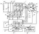
図1は、本実施例1のモータで車両を駆動するモータ制御システムの構成例である。(Example 1)
FIG. 1 is a configuration example of a motor control system that drives a vehicle with the motor of the first embodiment.
本発明に係る車両制御装置の一例である本実施例1のモータ制御システムは、主に、インバータ回路1と、モータ101と、バッテリ201と、コントローラ51と、を有して構成される。
The motor control system of the first embodiment, which is an example of the vehicle control device according to the present invention, mainly includes an
モータ101は、図示しない車両の駆動機構と接続されており、モータ101が回転することにより車両が推進する。また、本実施例1のモータ101は、三相永久磁石同期モータである。図1に示す102、103、104はモータ101に設けられた巻線である。モータ101は図示しないロータに設けられた永久磁石から発生する磁束と、図示しないステータに固定された巻線102、103、104に流れる電流により発生する磁界との相互作用により動作する。巻線102、103、104に流れる電流Iu、Iv、Iwは夫々U相電流、V相電流、W相電流である。電流Iu、Iv、Iwは、通常互いに120度の位相の異なる正弦波状の交流電流の形態となる。
The
モータ101は、温度センサ105を備える。温度センサ105は、モータ101の温度を検出し、検出した温度を示す温度センサ信号106を出力する。この温度センサ信号106は、コントローラ51に入力される。コントローラ51は、車両システムを制御する車両コントローラ53から入力されるトルク指令52により要求されるトルクをモータ101に与えるために、温度センサ信号106を含む各センサからの情報をもとにインバータ回路1を制御してモータ101に電流Iu、Iv、Iwを流し、モータ101を回転させるものである。コントローラ51の処理の詳細は図2を用いて後述する。
The
温度センサ信号106は、主にトルクの温度補償のために必要な情報である。モータ101のロータを構成する磁石から発生する磁束は温度依存性があるため、温度によってモータ101の巻線に流す電流Iw、Iv、Iwとモータ101に発生するトルクとの関係が変化するからである。
The
さらに、モータ101は、回転位置センサ107を備える。回転位置センサ107は、モータ101のロータの回転位置を回転角度として検出する機能を有する。回転位置センサ107は、検出した回転位置を示す回転位置センサ信号108を出力する。この回転位置センサ信号108は、コントローラ51に入力される。回転位置センサ信号108についてのコントローラ51における処理は図2を用いて後述する。
Further, the
電流センサ109、110、111は夫々電流Iu、Iv、Iwの電流量を検出し、それに基づいて電流センサ信号112、113、114を出力する。この電流センサ信号112、113、114は、コントローラ51に入力される。電流センサ信号112、113、114のコントローラ51における処理も図2を用いて後述する。
The
インバータ回路1は、スイッチング素子2、3、4、5、6、7と還流ダイオード8、9、10、11、12、13を含む。
The
本実施例1のスイッチング素子2、3、4、5、6、7は、IGBT(絶縁ゲートバイポーラトランジスタ)であり、ゲート端子、コレクタ端子、エミッタ端子を含む。還流ダイオード8、9、10、11、12、13は、スイッチング素子2、3、4、5、6、7のコレクタ端子とエミッタ端子との間に接続される。還流ダイオード8、9、10、11、12、13は、スイッチング素子2、3、4、5、6、7のコレクタ端子がエミッタ端子より高電位となる場合、還流ダイオード8、9、10、11、12、13を通じて電流を流し、スイッチング素子2、3、4、5、6、7に高い逆電圧がかかることを防止する。
The
スイッチング素子2、3、4、5、6、7のオンとオフの切替えは、スイッチング素子2、3、4、5、6、7のゲート端子に接続されるゲートドライブ信号14、15、16、17、18、19によって行われる。夫々のゲートドライブ信号14、15、16、17、18、19の元になる6本から成るゲート信号21は、コントローラ51により生成され、出力される。コントローラ51から出力されたゲート信号21は、ゲートドライブ回路20に入力される。
Switching the on and off of the
ゲートドライブ回路20は、ゲート信号21をスイッチング素子2、3、4、5、6、7のオンとオフの切り替えに必要な電位に変換してゲートドライブ信号14、15、16、17、18、19を出力する。コントローラ51におけるゲート信号21の生成は図2を用いて後述する。
The
スイッチング素子2のエミッタ端子とスイッチング素子3のコレクタ端子とは接続され、その接続点は巻線102に接続され電流Iuを流す。スイッチング素子4のエミッタ端子とスイッチング素子5のコレクタ端子とは接続され、その接続点は巻線103に接続され電流Ivを流す。スイッチング素子6のエミッタ端子とスイッチング素子7のコレクタ端子とは接続され、その接続点は巻線104に接続され電流Iwを流す。スイッチング素子2、4、6のコレクタ端子は、共通に接続され、高電位DC配線22につながれる。またスイッチング素子3、5、7のエミッタ端子は、共通に接続され、低電位DC配線23につながれる。
The emitter terminal of the
これにより、コントローラ51は、生成したゲート信号21をもとにスイッチング素子2、3、4、5、6、7のオンとオフを適切なタイミングで行い、巻線102、103、104に流れる電流Iu、Iv、Iwを制御し、モータ101の回転制御を実現する。通常、ゲート信号21は、電流Iu、Iv、Iwが互いに120度位相の異なる正弦波状の信号になるようPWM(パルス幅変調)信号の形態を成す。
As a result, the
電圧センサ25は、高電位DC配線22と低電位DC配線23に接続され、これらの電位差を検出する。高電位DC配線22と低電位DC配線23の電位差は通常例えば100V以上の高電圧であるため、電圧センサ25は、コントローラ51が検出可能な低電圧に変換したDC電圧センサ信号26を生成し、出力する。このDC電圧センサ信号26は、コントローラ51に入力される。
The
DC電流センサ27は、高電位DC配線22に流れる電流を検出する。DC電流センサ27は、検出した電流を示すDC電流センサ信号28を生成し、出力する。このDC電流センサ信号28は、コントローラ51に入力される。
The DC
インバータ回路1に含まれる平滑コンデンサ29は高電位DC配線22と低電位DC配線23との間に接続される。平滑コンデンサ29は、スイッチング素子2、3、4、5、6、7のスイッチング動作により発生するDC電圧の脈動を抑制する働きがある。
The smoothing
バッテリ201は、バッテリ201の高電位側の端子と高電位DC配線22が接続され、バッテリ201の低電位側の端子と低電位DC配線23が接続され、インバータ回路1やモータ101に電力供給する直流電源として働く。
In the
コンタクタ202は、バッテリ201の高電位側と高電位DC配線22との間に設けられる。コンタクタ202のオンとオフの動作によりバッテリ201とインバータ回路1との間の電力伝達とその遮断を実現する。コンタクタ202の動作制御は、車両コントローラ53からの指令を受けて、図示していないバッテリコントローラがオンとオフの動作を行う。
The
図2は、図1に示した実施例1においてモータ制御を行うコントローラ51の処理を説明する処理ブロック図である。
FIG. 2 is a processing block diagram illustrating the processing of the
コントローラ51での処理は、電流指令演算部61、電流制御部62、二相三相変換部65、ゲート制御信号演算部66、三相二相変換部67、位置速度演算部68、及びDC電圧上昇判定部71を含む。コントローラ51は、モータ101に三相の電流Iu、Iv、Iwを流して回転制御するが、コントローラ51の内部では三相交流系の座標からd軸とq軸で表される二相座標に変換した座標系にて処理する、いわゆるベクトル制御方式の手法が用いられる。
The processing by the
コンタクタ202がオンしてバッテリ201がインバータ回路1に接続された状態におけるコントローラ51の処理について説明する。
The processing of the
電流指令演算部61は、d軸電流指令値Id*及びq軸電流指令値Iq*を算出する。d軸電流指令値Id*及びq軸電流指令値Iq*はトルク指令52と回転速度ωと温度センサ信号106をもとに演算される。トルク指令52はモータ101が出力すべきトルクを示す。一般に、モータのトルクTは次式(1)の関係で表され、電流に依存する。
The current command calculation unit 61 calculates the d-axis current command value Id * and the q-axis current command value Iq *. The d-axis current command value Id * and the q-axis current command value Iq * are calculated based on the
T =α(A・IQ+B・ID・IQ) ・・・(1)
上記式(1)において、IDはd軸電流、IQはq軸電流、αはモータ極対数、Aは磁石磁束、Bはd軸とq軸とのインダクタンス差であり、モータによって決まる定数である。T = α (A ・ IQ + B ・ ID ・ IQ) ・ ・ ・ (1)
In the above equation (1), ID is the d-axis current, IQ is the q-axis current, α is the number of motor pole pairs, A is the magnetic flux of the magnet, and B is the inductance difference between the d-axis and the q-axis, which are constants determined by the motor. ..
回転速度ωは、回転位置センサ信号108をもとに位置速度演算部68によって求められ、出力される。モータ101の巻線102、103、104から誘起される起電力が回転速度ωに応じて変化するので、回転速度ωは電流に対して影響を与え、電流指令値の演算に必要となる。
The rotation speed ω is obtained by the position
温度センサ信号106は、モータ101のロータに設けられた永久磁石の磁束が温度によって変化し、その結果モータのトルクに影響を及ぼすため、電流指令値の温度補償を行うため必要な情報である。
The
位置速度演算部68は、回転位置センサ信号108をもとに回転速度ωを演算すると共に磁極位置θdを演算する。磁極位置θdは、二相三相変換部65と三相二相変換部67に入力され、d軸及びq軸の二相座標と三相座標との間の変換に使用される。三相二相変換部67は、三相電流Iu、Iv、Iwに対応する電流センサ信号112、113、114について、磁極位置θdの情報をもとにd軸q軸への座標変換を行い、d軸検知電流Idとq軸検知電流Iqを出力する。
The position
比較器63は、電流指令演算部61から出力されるd軸電流指令値Id*と三相二相変換部67から出力されるd軸検知電流Idとの偏差を演算し、d軸電流偏差ΔIdを出力する。
The
比較器64は、電流指令演算部61から出力されるq軸電流指令値Iq*と三相二相変換部67から出力されるq軸検知電流Iqとの偏差を演算し、q軸電流偏差ΔIqを出力する。
The
電流制御部62は、目標値である指令値と出力値である測定値との偏差を示すd軸差分電流ΔIdとq軸電流偏差ΔIqがゼロになるようにフィードバック制御を行い、出力値を更新するために電圧指令であるd軸電圧指令Vd*とq軸電圧指令Vq*を演算し、出力する。
The
電流制御部62が電圧の形態で指令値を出力するのは、ゲート制御信号演算部66から出力するゲート信号21が電圧で指令を定義するほうが都合の良いPWM信号であるためである。電流制御部62におけるフィードバック制御は例えばPI制御で行われる。
The
また、電流制御部62は、指令値をそのまま出力値とするフィードフォワード制御を実現するためにd軸電流指令値Id*とq軸電流指令Iq*を直接入力する経路を有する。電流制御部62は条件によってフィードバック制御とフィードフォワード制御の組合せを変更する場合があり、本発明に係る形態でも実施される。
Further, the
電流制御部62から出力されるd軸電圧指令値Vd*及びq軸電圧指令値Vq*は、二相三相変換部65に入力される。二相三相変換部65は、入力されたd軸電圧指令値Vd*及びq軸電圧指令値Vq*並びに磁極位置θdをもとに三相電圧指令値Vu*、Vv*、Vwを演算し、出力する。
The d-axis voltage command value Vd * and the q-axis voltage command value Vq * output from the
ゲート制御信号演算部66は、三相電圧指令値Vu*、Vv*、Vwと、図示しないキャリア搬送波との比較によりPWM信号である6本のゲート信号21を生成し、ゲートドライブ回路20に出力する。
The gate control
以上がコントローラ51の通常の処理である。次に本発明に係る処理を説明する。
The above is the normal processing of the
本実施例1では、DC電圧上昇判定部71をコントローラ51の処理に加える。DC電圧上昇判定部71は、DC電圧センサ信号26を入力してDC電圧が上昇する状態を検知することによりコンタクタ202の接続が開放されたことを判断するものである。
In the first embodiment, the DC voltage rise
車両が走行中に回生ブレーキを動作させると、回転するモータ101の巻線102、103、104の誘起電圧による電力は、インバータ回路1や接続されているコンタクタ202を介してバッテリ201に充電される状態となる。このときコンタクタ202が誤作動など何らかの原因で開放された場合、モータ101より生成された電力はバッテリ201に充電されずに平滑コンデンサ29に電荷が蓄積され、DC電圧センサ信号26に現れる電圧の上昇が検出される。そのため、電力回生制御時にDC電圧の上昇を感知することは、コンタクタ202の接続開放の判断する一手法となり得る。
When the regenerative brake is operated while the vehicle is running, the electric power generated by the induced voltages of the
また、コンタクタ202の接続開放の他の判断手法として、コンタクタ202の接続の実行や接続状態を監視するバッテリコントローラ(不図示)や、このバッテリコントローラへコンタクタ202の制御を指示する車両コントローラ53から、コンタクタ202の状態情報をコントローラ51に送って監視することが挙げられる。
Further, as another determination method for opening the connection of the
車両が電力回生制御中にコンタクタ202の接続が開放された場合、DC電圧は上昇し、DC電圧に接続されている平滑コンデンサ29などの回路部品の劣化や故障を引き起こすおそれがある。そこで、本発明では、コンタクタ202の接続が開放した場合にDC電圧の上昇を抑制し開放前の電圧に収束する制御を行い、回路部品の故障を防ぎコンタクタ202が再接続できるようにする手法を示す。
When the connection of the
図3は、本発明の実施例1に係る、コンタクタ202の接続が開放したことの検出や、その後の処理についての制御処理フローの一例を示したものである。
FIG. 3 shows an example of a control processing flow for detecting that the
ステップS1は、カウント値countを初期化する処理である。カウント値countは時間の経過を表すために用いる。 Step S1 is a process of initializing the count value count. The count value count is used to indicate the passage of time.
ステップS2は、タイマ割り込みであり、コントローラ内部に有する図示しないタイマをもとに、例えば125μ秒毎に割り込みが入り、次のステップに進む。 Step S2 is a timer interrupt, and an interrupt is input every 125 μs, for example, based on a timer (not shown) inside the controller, and the process proceeds to the next step.
ステップS3は、あらかじめ設定している電圧閾値V1(例えば840V)に対して、DC電圧上昇判定部71がDC電圧センサ信号26から得られるDC電圧情報との比較を行う。DC電圧情報が電圧閾値V1以下であれば、ステップS1に戻りカウント値countを初期化する。DC電圧情報が電圧閾値V1を超えているのであれば、ステップS4に進みカウント値countを一つ増やす。DC電圧情報が電圧閾値V1を超える理由がノイズの重畳などではなく、電圧上昇が理由で起きている確度を得るための一手法として、ステップS3では連続して所定期間DC電圧情報が電圧閾値V1を超えていることを検出する。
In step S3, the DC voltage rise
ステップS5は、ステップS4でインクリメントされたカウント値が所定の値(本実施例1では3)になる回数まで、ステップS3のDC電圧情報が電圧閾値V1を超えているかどうかを検出する。ステップS5でカウント値countが所定の値に到達したならば、125μ秒×3=375μ秒の間、DC電圧情報が電圧閾値V1を超えたと検知し、コンタクタ202の接続が開放されたと判断する。以上のステップS1からS5の処理が、図2のDC電圧上昇判定部71にて成される処理である。DC電圧上昇判定部71は判定結果72を出力する。判定結果72は図3のステップS5の判定結果出力に相当する。
Step S5 detects whether or not the DC voltage information in step S3 exceeds the voltage threshold value V1 until the number of times the count value incremented in step S4 reaches a predetermined value (3 in the first embodiment). When the count value count reaches a predetermined value in step S5, it is detected that the DC voltage information exceeds the voltage threshold value V1 for 125 μsec × 3 = 375 μsec, and it is determined that the connection of the
ステップS5がYESと判断されるとステップS6に進む。ステップS6の処理は、電流指令演算部61の中でq軸電流指令Iq*を所定の固定値に強制的に設定するものである。図2にはこの処理を模式的に表現し、電流指令演算部61の内部にq軸電流指令固定値設定73を設けている。電流指令演算部61は、このq軸電流指令固定値設定73と、電流指令演算部61が出力するq軸電流指令Iq*とを、スイッチ74を介して接続している。スイッチ74はDC電圧上昇判定部71から出力される判定結果72によりオンとオフの動作が制御される。またステップS6の処理は、図示していないが、電流制御部62は、q軸電流指令Iq*が直接入力されるフィードフォワード制御を主体に行い、q軸電流偏差ΔIqによるフィードバック制御は成されない、あるいは電流制御に関与する割合を減らす。また、q軸電流指令固定値設定73に設定されるq軸電流指令値Iq*は、DCバスに流れる電流が0Aになるようにあらかじめ設定する。具体的な設定値は車両システムの特性によって異なるので、実験等により求めることになるが、Iq*=0Aに近い値になる。
If it is determined that step S5 is YES, the process proceeds to step S6. In the process of step S6, the q-axis current command Iq * is forcibly set to a predetermined fixed value in the current command calculation unit 61. FIG. 2 schematically represents this process, and a q-axis current command fixed value setting 73 is provided inside the current command calculation unit 61. The current command calculation unit 61 connects the q-axis current command fixed value setting 73 and the q-axis current command Iq * output by the current command calculation unit 61 via a
ステップS7は、ステップS2と同様、定期的なタイミングで次のステップS8のDC電圧の判定を行うためにある。 Similar to step S2, step S7 is for determining the DC voltage of the next step S8 at a periodic timing.
ステップS8は、DC電圧情報が電圧閾値V2より低いかどうかを検出する。ステップS6の制御によりDC電圧の上昇が収まると、DC電圧は電圧閾値V1を超えた電圧を維持する。その状態でコンタクタ202が開放状態(オフ)から接続状態(オン)に変化すると、DC電圧はバッテリ201の起電力に近づくため電圧が低下する。ステップS8は、ノイズ重畳の影響も考慮し電圧低下が発生している確度を高めるため、電圧閾値V2を電圧閾値V1より低く設定し(例えば820V)、コンタクタ202が再度接続されたことを判断する。電圧閾値V2よりDC電圧が下がらない場合が続くときは、ステップS7に戻り次の所定タイミングでステップS8に移りDC電圧の比較を繰り返す。
Step S8 detects whether the DC voltage information is lower than the voltage threshold value V2. When the increase in the DC voltage is stopped by the control in step S6, the DC voltage maintains the voltage exceeding the voltage threshold value V1. When the contactor 202 changes from the open state (off) to the connected state (on) in that state, the DC voltage approaches the electromotive force of the
ステップS8でコンタクタ202が再度接続されたと判断したならばステップS9に進み、電流指令演算部61から出力されるq軸電流指令値Iq*を、コンタクタ202が開放される以前のトルク指令52をもとに演算される値に戻す。図2においてこの処理は、DC電圧上昇判定部71により判定結果72を出力しスイッチ74をオフし、電流指令演算部61の処理を従来の演算に戻すことに相当する。
If it is determined in step S8 that the
図4は、本発明の実施例1に係るコントローラ51の処理における各信号や状態を説明するタイミング図である。これは車両が回生動作中にコンタクタ202の接続が開放され、その後、コンタクタ202が再接続された場合の例である。
FIG. 4 is a timing diagram illustrating each signal and state in the processing of the
時間T0は、DC電圧上昇判定部71によりDC電圧センサ信号26が電圧閾値V1より高い電圧であることを感知したタイミングである。時間T0より前の期間では、回生動作によりDC電流センサ信号28は250Aの電流がインバータ回路1からバッテリ201に向けて流れている。ここでDC電流センサ信号28が負の値をとる場合は回生動作時であり、正の値を取るときはバッテリ201からインバータ回路1に電流の流れる力行動作の場合であると定義する。
The time T0 is the timing at which the DC voltage rise
時間T0より前の期間では、q軸電流指令値Iq*に指定された電流値(本実施例では−100A)の通りにq軸電流Iqが流れている。またd軸電流指令値Id*は所定の回生電流を得るために所定の電流値(本実施例1では−100A)が設定されている。DC電圧センサ信号26は時間T0の直前で電圧上昇が発生する。この電圧上昇が発生した瞬間は、コンタクタ202の接続が開放された瞬間を想定している。
In the period before the time T0, the q-axis current Iq flows according to the current value (-100A in this embodiment) specified in the q-axis current command value Iq *. Further, the d-axis current command value Id * is set to a predetermined current value (-100A in the first embodiment) in order to obtain a predetermined regenerative current. The voltage of the DC
DC電圧上昇判定部71によるコンタクタ202の接続が開放されたことの判断は、図3で示した処理フローのステップS2からS5の通り、コントローラ内部のタイマによる一定の期間、DC電圧センサ信号26が継続して電圧閾値V1を上まわっていることを確認してから、制御の処理方法を変更する。
The determination by the DC voltage rise
時間T1は、DC電圧上昇判定部71がコンタクタ202の接続が開放されたと判断したタイミングである。時間T0から時間T1の期間は回生されている電流が平滑コンデンサ29に流れ込み、平滑コンデンサ29の両端にかかる電圧が高くなる。そこで、素子を保護するために、例えば平滑コンデンサ29にかかる電圧をその耐圧以下に保つようにするには、時間T0から時間T1の期間を適切に設定する必要がある。本実施例では図3と図4で示したようにコントローラ51の内部にあるクロック(本実施例1では125μ秒周期)とそのカウント数(本実施例1では3カウント)で時間T0から時間T1の期間を決めているが、使用する回路素子の耐圧などを考慮して適宜設定されるべきである。
The time T1 is the timing when the DC voltage rise
時間T1にてコンタクタ202の接続が開放されたと判断すると、q軸電流指令値Iq*を0Aに近い固定値(この実施例1では0A)に強制的に設定する。その結果、q軸電流Iqは0Aに収束するように制御される。d軸指令値Id*はモータ101の巻線102、103、104の誘起電圧を抑制するように電流指令演算部61により算出される。d軸電流指令値Id*は時間T1より以前の回生動作時の値よりも電流値は増える傾向になる。その結果、時間T1以降DC電圧センサ信号26の電圧上昇は収まり、DC電流センサ信号28はほぼゼロに収束する。
When it is determined that the connection of the
時間T2は、コンタクタ202が再度接続したことを判断したタイミングである。時間T2の直前にコンタクタ202の再接続が起こると、DC電圧センサ信号26の電圧は急激に降下し、バッテリ201の起電力に近づく。そのため、DC電圧上昇判定部71は、時間T2のタイミングでDC電圧センサ信号26の電圧が電圧閾値V2より低いことを検出し、コンタクタ202が再接続したことを判断する。そして、DC電圧上昇判定部71は、先に図3のステップS9での説明の通り、q軸電流指令値Iq*の強制設定を解除し従来の制御に戻す。図4の例ではコンタクタ202の再接続を判断した後、q軸電流指令値Iq*を急に元の設定値(ここでは−100A)に戻さず滑らかに変化させている。これにより、急激なトルク変動を抑制し、車両の滑らかな動作を実現する。
The time T2 is the timing when it is determined that the
実施例1に示した手法によりコンタクタ202の接続の開放や再接続の判断を可能とし、コンタクタ202の開放している期間にDC電圧の上昇を抑制した上でモータのトルク制御を継続できるので、コンタクタ202の再接続を容易に実現できる。
The method shown in Example 1 makes it possible to determine whether to open or reconnect the
本実施例1によれば、コンタクタ202が開放状態になった場合でも、過電圧を抑制した上でモータ101のトルク制御を継続できるので、コンタクタ202を再接続してもモータ101のトルク制御の継続を可能とする。
According to the first embodiment, even when the
(実施例2)
実施例2は、実施例1と同様な効果を得るもう一つの例であり、特にセンサの出力値に含まれる誤差によってはDC電圧の上昇が収まらない場合を考慮した例である。(Example 2)
The second embodiment is another example in which the same effect as that of the first embodiment is obtained, and is an example considering a case where the increase in the DC voltage does not stop due to an error included in the output value of the sensor.
図5は、本発明の実施例2に係るモータ制御を行うコントローラ51の処理を説明する処理ブロック図である。図6は、その処理手順を示す処理フロー図である。図5におけるコントローラ51の処理ブロックについて、図2とは異なる構成を中心に説明する。
FIG. 5 is a processing block diagram illustrating the processing of the
車両コントローラ53から出力されたトルク指令52は、セレクタ84の0側端子に入力される。セレクタ84のもう一方の1側端子には、実施例2に特徴的なコンタクタ開放時トルク指令83が接続される。
The
コンタクタ開放時トルク指令83の生成方法を説明する。DC電流設定80は、目標DC電流の設定であり、例えば0Aと設定する。比較器81は、入力されるDC電流設定80とDC電流センサ信号28とを比較し、DC電流偏差ΔIdcを出力する。PI制御部82は、DC電流偏差ΔIdcを入力し、DC電流偏差ΔIdcが0になるようにPI制御のフィードバック制御を行い、トルク指令の形態でコンタクタ開放時トルク指令83を出力する。
A method of generating the
DC電圧上昇判定部71は、図2などで説明したのと同様に、DC電圧センサ信号26の電圧を検知した結果、コンタクタ202の接続が開放したかどうかの判断を判定結果72としてセレクタ84に出力する。
As described in FIG. 2, the DC voltage rise
セレクタ84は、通常(DC電圧上昇判定部71がコンタクタ202の接続が開放されたと判断しない場合)そのスイッチは0側端子に倒され(0側端子に接続され)、車両コントローラ53から出力されるトルク指令52は、コントローラ51の内部に取り込まれた内部トルク指令85として電流指令演算部61に入力され、正常時のモータ制御が実行される。
The
DC電圧上昇判定部71がコンタクタ202の接続が開放されたと判断した場合、判定結果72の出力によりセレクタ84のスイッチは1側端子に倒される(1側端子に接続される)。これによりコンタクタ開放時トルク指令83がセレクタ84によって選択され、内部トルク指令85として電流指令演算部61に入力される。
When the DC voltage rise
以上の構成より、コンタクタ202の接続が開放されたと判断した場合、PI制御部82はDC電流センサ信号28が0Aになるようにトルク指令値を演算し、その演算結果であるコンタクタ開放時トルク指令83を電流指令演算部61にトルク指令として入力することによりフィードバック制御系が形成される。その結果、DC電流は0に制御され、平滑コンデンサ29に流れ込む電流もゼロに収束し、これにかかる電圧の上昇を防ぐことができる。
From the above configuration, when it is determined that the connection of the
図5の構成に対応する処理フローを示す図6を説明する。ステップS1からステップS5は前述の図3の処理フローと全く同じであり、DC電圧上昇判定部71によるコンタクタ202の接続が開放された判定をする処理である。
FIG. 6 showing a processing flow corresponding to the configuration of FIG. 5 will be described. Steps S1 to S5 are exactly the same as the processing flow of FIG. 3 described above, and are processing for determining that the connection of the
ステップS5にてコンタクタ202の開放を判断しYESに進むと、ステップS10にてDC電流が0になるようにPI制御部82が生成したコンタクタ開放時トルク指令83は、電流指令演算部61に入力される内部トルク指令85に適用される。
When the release of the
ステップS10の後のステップS7とステップS8も前述の図3の処理フローと全く同じであり、DC電圧上昇判定部71によるコンタクタ202が再接続された判定をする処理である。
Steps S7 and S8 after step S10 are exactly the same as the processing flow of FIG. 3 described above, and are processing for determining that the
ステップS8にてコンタクタ202の再接続を判断しYESに進むと、ステップS11ではセレクタ84が0側端子に倒され(0側端子に接続され)、通常のトルク指令52をもとにモータ制御が実施される。
When the reconnection of the
実施例2に示した手法によりコンタクタ202の接続の開放や再接続の判断を可能とし、コンタクタ202の開放している期間にDC電圧の上昇を抑制した上でモータ101のトルク制御を継続できるので、コンタクタ202の再接続を容易に実現できる。また、制御対象をDC電流としたことで、より直接的に平滑コンデンサ29に流れる電流を制御できるので、DC電流センサ27以外のセンサの誤差などの影響を除いた精度の良い制御を可能とする。
By the method shown in the second embodiment, it is possible to determine whether the
(実施例3)
実施例3は実施例1や実施例2の処理と共に実施する車両制御に関する例である。コンタクタ202の接続が解放されたとき、実施例1や実施例2を実施すると、今まで回生制御により発生していた制動トルクがほぼ無くなる。これによりコンタクタ202の接続が開放された直後から車両の速度の落ち方が遅くなるため、車両の運転手はブレーキのかかり方が弱くなった違和感を抱くおそれがある。(Example 3)
Example 3 is an example relating to vehicle control carried out together with the processing of Example 1 and Example 2. When the first and second embodiments are carried out when the connection of the
そこで、実施例3は、コンタクタ202の接続が開放されたときに実施例1や実施例2にて実施する処理と共に、不足した回生制御による制動トルクを摩擦ブレーキによって補う処理を行うものである。
Therefore, in the third embodiment, in addition to the processing performed in the first and second embodiments when the connection of the
図7は、先に説明した図1のモータで車両を駆動するモータ制御システムの構成例に対し、構成要素を加え実施例3を説明するものである。 FIG. 7 illustrates Example 3 by adding components to the configuration example of the motor control system for driving the vehicle with the motor of FIG. 1 described above.
要求制動力91は、運転手がブレーキペダルを踏むことにより検出される、運転手が車両に要求する制動力の情報である。要求制動力91が入力された車両コントローラ53は、その内部に有する回生・摩擦ブレーキ協調制御部92にて、要求された制動力を回生ブレーキ量と摩擦ブレーキ量とに適切に振り分ける演算を行い、夫々の必要ブレーキ量をモータ101による回生制御を司るコントローラ51と機械的なブレーキの制御を司るブレーキコントローラ96とに要求する。
The required
ブレーキコントローラ96は、演算処理を行う摩擦ブレーキ制御部97を有する。摩擦ブレーキ制御部97は、回生・摩擦ブレーキ協調制御部92から入力された摩擦ブレーキ要求値98に基づき図示しない車両に設けられた機械的ブレーキの特性に合った制御量を演算し、ブレーキコントローラ96を通じて機械的ブレーキを動作させ摩擦による制動力を生成する。
The
コントローラ51は、制動力演算部93を有する。制動力演算部93は、回生・摩擦ブレーキ協調制御部92との間で通信を行う。回生・摩擦ブレーキ協調制御部92は、回生ブレーキ要求値94を制動力演算部93に出力する。それに対して制動力演算部93は回生・摩擦ブレーキ協調制御部92に回生ブレーキステータス95を出力する。
The
ここで回生ブレーキ要求値94と回生ブレーキステータス95の形態の例を挙げる。回生・摩擦ブレーキ協調制御部92は、要求するブレーキ量の情報を回生ブレーキ要求値94として制動力演算部93に送信する。これを受信した制動力演算部93は現状発生している回生制動力の情報と、現状の状態から判断した可能な最大回生制動力の情報を回生ブレーキステータス95として回生・摩擦ブレーキ協調制御部92に送信する。これらの情報をもとに回生・摩擦ブレーキ協調制御部92は制動力演算部93と摩擦ブレーキ制御部97とに分配する適切な制動力の要求量を求める。
Here, an example of the form of the regenerative brake required
適切な制動力の分配の例として、現状発生している回生制動力が可能な最大回生制動力に達しておらず、要求制動力91が最大回生制動力より大きな場合、回生エネルギーを最大回収する目的において、回生・摩擦ブレーキ協調制御部92は、回生ブレーキ要求値94を可能な最大回生制動力に相当する値に設定し、要求制動力91から回生ブレーキ要求値94を差し引いた量を摩擦ブレーキ要求値98に設定することが挙げられる。
As an example of appropriate braking force distribution, if the currently generated regenerative braking force does not reach the maximum regenerative braking force that is possible and the required braking
また車両コントローラ53は、回生ブレーキステータス95をもとに演算された回生ブレーキ要求値94とともに、コントローラ51に出力するトルク指令52を更新することになる。
Further, the
ここで実施例1や実施例2で示したコンタクタ202の接続が開放された場合について説明する。コンタクタ202の接続が開放すると本発明ではq軸電流Iqをゼロにするように制御を行う。このときモータ101には、式(1)にも示したとおり、トルクは発生せず制動トルクはゼロとなる。この場合、制動力演算部93から回生・摩擦ブレーキ協調制御部92に送信する回生ブレーキステータス95に含まれる可能な最大回生制動力をゼロに設定する。これをもとに回生・摩擦ブレーキ協調制御部92は、運転手より要求された要求制動力91から回生ブレーキステータス95に含まれる現状の回生ブレーキ量を差し引いた分を摩擦ブレーキ要求値98に振り分け、回生ブレーキ要求値94をゼロに設定する。以上の処理によりコンタクタ202が開放しても制動トルクは急変せず、運転手に車両走行時の違和感を与えずに済む。
Here, a case where the connection of the
なお、本発明は上記した実施例に限定されるものではなく、様々な変形例が含まれる。例えば、上記した実施例は本発明を分かりやすく説明するために詳細に説明したものであり、必ずしも説明した全ての構成を備えるものに限定されるものではない。 The present invention is not limited to the above-described embodiment, and includes various modifications. For example, the above-described embodiment has been described in detail in order to explain the present invention in an easy-to-understand manner, and is not necessarily limited to the one including all the described configurations.
また、ある実施例の構成の一部を他の実施例の構成に置き換えることが可能であり、また、ある実施例の構成に他の実施例の構成を加えることも可能である。 Further, it is possible to replace a part of the configuration of one embodiment with the configuration of another embodiment, and it is also possible to add the configuration of another embodiment to the configuration of one embodiment.
また、各実施例の構成の一部について、他の構成の追加・削除・置換をすることが可能である。 Further, it is possible to add / delete / replace a part of the configuration of each embodiment with another configuration.
また、上記の各構成、機能、処理部、処理手段等は、それらの一部又は全部を、例えば集積回路で設計する等によりハードウェアで実現してもよい。 Further, each of the above configurations, functions, processing units, processing means and the like may be realized by hardware by designing a part or all of them by, for example, an integrated circuit.
また、上記の各構成、機能等は、プロセッサがそれぞれの機能を実現するプログラムを解釈し、実行することによりソフトウェアで実現してもよい。 Further, each of the above configurations, functions, and the like may be realized by software by the processor interpreting and executing a program that realizes each function.
1・・・インバータ回路、2、3、4、5、6、7・・・スイッチング素子、29・・平滑コンデンサ、51・・・コントローラ、52…トルク指令、53・・・車両コントローラ、101・・・モータ、201・・・バッテリ、202・・・コンタクタ 1 ... Inverter circuit, 2, 3, 4, 5, 6, 7 ... Switching element, 29 ... Smoothing capacitor, 51 ... Controller, 52 ... Torque command, 53 ... Vehicle controller, 101 ...・ ・ Motor, 201 ・ ・ ・ Battery, 202 ・ ・ ・ Contactor
Claims (2)
スイッチング素子により構成され、前記モータを駆動するインバータ回路と、
前記インバータ回路に接続され、前記モータを駆動する電力を供給するバッテリと、
前記バッテリと前記インバータ回路との間に接続されるコンデンサと、
前記バッテリと前記コンデンサとの間に接続されるコンタクタと、
前記コンタクタがオフである場合、前記インバータ回路と前記モータとの間の電圧が前記コンデンサ側に印加される電圧に近づくように、前記インバータ回路と前記モータとの間で電流を流す制御部と、
を備え、
前記制御部は、前記モータをベクトル制御し、
前記制御部は、
前記コンデンサの両端の電圧を検出する電圧センサと、
前記バッテリの高電位側を流れる電流を検出する電流センサと、
前記電流センサで検出した電流を目標電流に近づけるトルク指令を演算して出力するフィードバック制御部と、
ベクトル制御のq軸電流指令値及びd軸電流指令値を出力する電流指令演算部と、
を有し、
前記電流指令演算部は、前記電圧センサで検出した電圧が第1の閾値電圧以下であった場合、外部から入力されたトルク指令に基づいて前記d軸電流指令値及び前記q軸電流指令値を演算して出力し、前記電圧センサで検出した電圧が前記第1の閾値電圧以下であった後に前記第1の閾値電圧を超えた場合、前記フィードバック制御部が出力したトルク指令に基づいて前記d軸電流指令値及び前記q軸電流指令値を演算して出力し、前記電圧センサで検出した電圧が前記第1の閾値電圧を超えた後に前記第1の閾値電圧より低い第2の閾値電圧より低くなった場合、外部から入力されたトルク指令に基づいて前記d軸電流指令値及び前記q軸電流指令値を演算して出力することを特徴とする車両制御装置。 A motor that generates the driving force of the vehicle and
An inverter circuit that is composed of switching elements and drives the motor,
A battery connected to the inverter circuit and supplying electric power to drive the motor,
A capacitor connected between the battery and the inverter circuit,
A contactor connected between the battery and the capacitor,
When the contactor is off, a control unit that allows a current to flow between the inverter circuit and the motor so that the voltage between the inverter circuit and the motor approaches the voltage applied to the capacitor side.
Equipped with
The control unit vector-controls the motor and controls the motor.
The control unit
A voltage sensor that detects the voltage across the capacitor and
A current sensor that detects the current flowing on the high potential side of the battery, and
A feedback control unit that calculates and outputs a torque command that brings the current detected by the current sensor closer to the target current, and
A current command calculation unit that outputs the q-axis current command value and d-axis current command value of vector control,
Have,
When the voltage detected by the voltage sensor is equal to or less than the first threshold voltage, the current command calculation unit calculates the d-axis current command value and the q-axis current command value based on the torque command input from the outside. When the voltage detected by the voltage sensor is equal to or less than the first threshold voltage and then exceeds the first threshold voltage, the d is based on the torque command output by the feedback control unit. The axis current command value and the q-axis current command value are calculated and output, and after the voltage detected by the voltage sensor exceeds the first threshold voltage, the voltage is lower than the first threshold voltage and is lower than the second threshold voltage. A vehicle control device characterized in that when it becomes low, the d-axis current command value and the q-axis current command value are calculated and output based on a torque command input from the outside.
摩擦により車両の制動力を発生させるブレーキ部と、
前記ブレーキ部の制動力を制御する摩擦ブレーキ制御部と、
現在の回生制動力を求める制動力演算部と、
前記制動力演算部で求めた回生制動力に基づいて、前記摩擦ブレーキ制御部が制御する前記ブレーキ部の制動力を前記摩擦ブレーキ制御部に対して出力する回生・摩擦ブレーキ協調制御部と、
をさらに備えることを特徴とする車両制御装置。 In the vehicle control device according to claim 1,
The brake part that generates the braking force of the vehicle by friction,
A friction brake control unit that controls the braking force of the brake unit,
The braking force calculation unit that obtains the current regenerative braking force,
A regenerative / friction brake coordinated control unit that outputs the braking force of the brake unit controlled by the friction brake control unit to the friction brake control unit based on the regenerative braking force obtained by the braking force calculation unit.
A vehicle control device characterized by further comprising.
Applications Claiming Priority (3)
| Application Number | Priority Date | Filing Date | Title |
|---|---|---|---|
| JP2018042358 | 2018-03-08 | ||
| JP2018042358 | 2018-03-08 | ||
| PCT/JP2019/003288 WO2019171836A1 (en) | 2018-03-08 | 2019-01-31 | Vehicle control device |
Publications (2)
| Publication Number | Publication Date |
|---|---|
| JPWO2019171836A1 JPWO2019171836A1 (en) | 2020-12-03 |
| JP6983305B2 true JP6983305B2 (en) | 2021-12-17 |
Family
ID=67847122
Family Applications (1)
| Application Number | Title | Priority Date | Filing Date |
|---|---|---|---|
| JP2020504856A Active JP6983305B2 (en) | 2018-03-08 | 2019-01-31 | Vehicle control device |
Country Status (2)
| Country | Link |
|---|---|
| JP (1) | JP6983305B2 (en) |
| WO (1) | WO2019171836A1 (en) |
Family Cites Families (5)
| Publication number | Priority date | Publication date | Assignee | Title |
|---|---|---|---|---|
| JP3565355B2 (en) * | 1994-07-28 | 2004-09-15 | 株式会社ボッシュオートモーティブシステム | Regenerative brake interlocking friction brake system |
| JP5287705B2 (en) * | 2009-08-28 | 2013-09-11 | トヨタ自動車株式会社 | VEHICLE DRIVE DEVICE AND ITS CONTROL METHOD |
| JP5645083B2 (en) * | 2011-06-28 | 2014-12-24 | アイシン・エィ・ダブリュ株式会社 | Rotating electrical machine control device |
| JP5910757B2 (en) * | 2012-11-29 | 2016-04-27 | 富士電機株式会社 | Electric motor control device |
| JP6201867B2 (en) * | 2014-03-31 | 2017-09-27 | アイシン・エィ・ダブリュ株式会社 | Inverter control device |
-
2019
- 2019-01-31 JP JP2020504856A patent/JP6983305B2/en active Active
- 2019-01-31 WO PCT/JP2019/003288 patent/WO2019171836A1/en active Application Filing
Also Published As
| Publication number | Publication date |
|---|---|
| WO2019171836A1 (en) | 2019-09-12 |
| JPWO2019171836A1 (en) | 2020-12-03 |
Similar Documents
| Publication | Publication Date | Title |
|---|---|---|
| US9903931B2 (en) | Diagnostic device for voltage sensors | |
| EP3281844B1 (en) | Motor control device | |
| CN110460254B (en) | Control circuit for power converter | |
| US9054626B2 (en) | Motor control apparatus | |
| JP4921883B2 (en) | Electric vehicle control device | |
| JP6173516B1 (en) | Electric motor control apparatus and electric motor control method | |
| JP2011019302A (en) | Controller for motor driving system | |
| JPH1169900A (en) | Controller for electric rolling stock | |
| JP6216639B2 (en) | Motor control device | |
| JP6983305B2 (en) | Vehicle control device | |
| JP4784290B2 (en) | Motor drive device | |
| WO2015001849A1 (en) | Electric-vehicle braking control device | |
| JP6203318B1 (en) | Electric motor control apparatus and electric motor control method | |
| JP2019170057A (en) | Motor control device | |
| US11077754B2 (en) | In-vehicle control apparatus and program | |
| JP6663368B2 (en) | Motor control device | |
| JP7047056B2 (en) | Motor control device | |
| JP6708843B2 (en) | Drive | |
| JP7276277B2 (en) | Power converter control circuit | |
| JP7466778B2 (en) | MOTOR CONTROL DEVICE, ELECTRIC POWER STEERING DEVICE, AND MOTOR CONTROL METHOD | |
| JP2012147658A (en) | Motor drive controller |
Legal Events
| Date | Code | Title | Description |
|---|---|---|---|
| A621 | Written request for application examination |
Free format text: JAPANESE INTERMEDIATE CODE: A621 Effective date: 20200417 |
|
| A131 | Notification of reasons for refusal |
Free format text: JAPANESE INTERMEDIATE CODE: A131 Effective date: 20210406 |
|
| A521 | Written amendment |
Free format text: JAPANESE INTERMEDIATE CODE: A523 Effective date: 20210531 |
|
| TRDD | Decision of grant or rejection written | ||
| A01 | Written decision to grant a patent or to grant a registration (utility model) |
Free format text: JAPANESE INTERMEDIATE CODE: A01 Effective date: 20211109 |
|
| A61 | First payment of annual fees (during grant procedure) |
Free format text: JAPANESE INTERMEDIATE CODE: A61 Effective date: 20211122 |
|
| R150 | Certificate of patent or registration of utility model |
Ref document number: 6983305 Country of ref document: JP Free format text: JAPANESE INTERMEDIATE CODE: R150 |