JP6983180B2 - Process related to cell co-culture chip and its production - Google Patents
Process related to cell co-culture chip and its production Download PDFInfo
- Publication number
- JP6983180B2 JP6983180B2 JP2018559754A JP2018559754A JP6983180B2 JP 6983180 B2 JP6983180 B2 JP 6983180B2 JP 2018559754 A JP2018559754 A JP 2018559754A JP 2018559754 A JP2018559754 A JP 2018559754A JP 6983180 B2 JP6983180 B2 JP 6983180B2
- Authority
- JP
- Japan
- Prior art keywords
- support
- value
- perforation
- diameter
- protrusion
- Prior art date
- Legal status (The legal status is an assumption and is not a legal conclusion. Google has not performed a legal analysis and makes no representation as to the accuracy of the status listed.)
- Active
Links
Images


Classifications
-
- B—PERFORMING OPERATIONS; TRANSPORTING
- B01—PHYSICAL OR CHEMICAL PROCESSES OR APPARATUS IN GENERAL
- B01L—CHEMICAL OR PHYSICAL LABORATORY APPARATUS FOR GENERAL USE
- B01L3/00—Containers or dishes for laboratory use, e.g. laboratory glassware; Droppers
- B01L3/50—Containers for the purpose of retaining a material to be analysed, e.g. test tubes
- B01L3/502—Containers for the purpose of retaining a material to be analysed, e.g. test tubes with fluid transport, e.g. in multi-compartment structures
- B01L3/5027—Containers for the purpose of retaining a material to be analysed, e.g. test tubes with fluid transport, e.g. in multi-compartment structures by integrated microfluidic structures, i.e. dimensions of channels and chambers are such that surface tension forces are important, e.g. lab-on-a-chip
- B01L3/502707—Containers for the purpose of retaining a material to be analysed, e.g. test tubes with fluid transport, e.g. in multi-compartment structures by integrated microfluidic structures, i.e. dimensions of channels and chambers are such that surface tension forces are important, e.g. lab-on-a-chip characterised by the manufacture of the container or its components
-
- C—CHEMISTRY; METALLURGY
- C12—BIOCHEMISTRY; BEER; SPIRITS; WINE; VINEGAR; MICROBIOLOGY; ENZYMOLOGY; MUTATION OR GENETIC ENGINEERING
- C12M—APPARATUS FOR ENZYMOLOGY OR MICROBIOLOGY; APPARATUS FOR CULTURING MICROORGANISMS FOR PRODUCING BIOMASS, FOR GROWING CELLS OR FOR OBTAINING FERMENTATION OR METABOLIC PRODUCTS, i.e. BIOREACTORS OR FERMENTERS
- C12M23/00—Constructional details, e.g. recesses, hinges
- C12M23/02—Form or structure of the vessel
- C12M23/16—Microfluidic devices; Capillary tubes
-
- C—CHEMISTRY; METALLURGY
- C12—BIOCHEMISTRY; BEER; SPIRITS; WINE; VINEGAR; MICROBIOLOGY; ENZYMOLOGY; MUTATION OR GENETIC ENGINEERING
- C12M—APPARATUS FOR ENZYMOLOGY OR MICROBIOLOGY; APPARATUS FOR CULTURING MICROORGANISMS FOR PRODUCING BIOMASS, FOR GROWING CELLS OR FOR OBTAINING FERMENTATION OR METABOLIC PRODUCTS, i.e. BIOREACTORS OR FERMENTERS
- C12M21/00—Bioreactors or fermenters specially adapted for specific uses
- C12M21/08—Bioreactors or fermenters specially adapted for specific uses for producing artificial tissue or for ex-vivo cultivation of tissue
-
- C—CHEMISTRY; METALLURGY
- C12—BIOCHEMISTRY; BEER; SPIRITS; WINE; VINEGAR; MICROBIOLOGY; ENZYMOLOGY; MUTATION OR GENETIC ENGINEERING
- C12M—APPARATUS FOR ENZYMOLOGY OR MICROBIOLOGY; APPARATUS FOR CULTURING MICROORGANISMS FOR PRODUCING BIOMASS, FOR GROWING CELLS OR FOR OBTAINING FERMENTATION OR METABOLIC PRODUCTS, i.e. BIOREACTORS OR FERMENTERS
- C12M25/00—Means for supporting, enclosing or fixing the microorganisms, e.g. immunocoatings
- C12M25/02—Membranes; Filters
- C12M25/04—Membranes; Filters in combination with well or multiwell plates, i.e. culture inserts
Landscapes
- Health & Medical Sciences (AREA)
- Chemical & Material Sciences (AREA)
- Life Sciences & Earth Sciences (AREA)
- Engineering & Computer Science (AREA)
- Zoology (AREA)
- Wood Science & Technology (AREA)
- Bioinformatics & Cheminformatics (AREA)
- Organic Chemistry (AREA)
- Biomedical Technology (AREA)
- Genetics & Genomics (AREA)
- General Health & Medical Sciences (AREA)
- Sustainable Development (AREA)
- Biotechnology (AREA)
- Biochemistry (AREA)
- General Engineering & Computer Science (AREA)
- Microbiology (AREA)
- Immunology (AREA)
- Clinical Laboratory Science (AREA)
- Dispersion Chemistry (AREA)
- Molecular Biology (AREA)
- Analytical Chemistry (AREA)
- Hematology (AREA)
- Chemical Kinetics & Catalysis (AREA)
- Apparatus Associated With Microorganisms And Enzymes (AREA)
- Micro-Organisms Or Cultivation Processes Thereof (AREA)
Description
本発明は、「モジュール」との用語によって各々参照され且つ2つずつ組み立てられる可能性のある、複数の部品を備えるマイクロ流体細胞培養チップに関する。 The present invention relates to a microfluidic cell culture chip with multiple components, each referred to by the term "module" and which may be assembled in pairs.
本発明はまた、前記チップを製造するためのプロセス、及び、診断の分野におけるその使用に関する。 The present invention also relates to a process for manufacturing the chip and its use in the field of diagnosis.
チップ上で臓器を真似る目的で発展した多数の現在のデバイスは、2D膜から成る。 Many current devices developed for the purpose of mimicking organs on chips consist of 2D membranes.
2011年10月13日に出願されたIngber等による特許US8647861B2において、著者は、組織/組織界面にて生体内で存在する機械的応力を再現するために、膜の周りで差圧を生成するし、そのためその膨張又は収縮を発生させること可能にさせる、手段を備えた、膜のいずれかの上で接着細胞の共培養を可能にさせる有機模倣デバイスを発展させた。このデバイスは、2つのマイクロ流体ダクトの界面で、ポリジメチルシロキサン(PDMS)で作製された柔軟な多孔質膜を備えるマイクロ流体システムに基づき、前記膜に沿って流体の循環を可能にさせ、特に呼吸の間の肺胞を真似ることを可能にさせる。 In patent US8647861B2 by Ingber et al., Filed October 13, 2011, the author creates a differential pressure around the membrane to reproduce the mechanical stresses present in vivo at the tissue / tissue interface. , Therefore developed an organic mimicking device that allows co-culture of adherent cells on any of the membranes, with the means capable of causing its expansion or contraction. The device is based on a microfluidic system with a flexible porous membrane made of polydimethylsiloxane (PDMS) at the interface of two microfluidic ducts, allowing fluid circulation along the membrane, in particular. Allows to imitate the alveolar during breathing.
2012年2月28日に出願されたIngber等による特許US2014/0038279A1において、著者は、自然の腸上皮構造を再現しその挙動を真似ることを可能にさせる細胞共培養システムを提案する。マイクロ流体システムに基づいたこの有機模倣デバイスは、前記膜に沿った流体の循環を可能にさせる2つのマイクロ流体ダクトの界面に位置付けられたPDMS多孔質膜を備え、その上で腸上皮細胞の層が側面の内の少なくとも1つの上で培養される。支持体要素による膜の結合は、少なくとも1つの寸法において膜を長くする動きにつながるので、生体内での組織の動きを再現することを可能にさせる。 In US 2014/0038279A1 by Ingber et al., Filed on February 28, 2012, the author proposes a cell co-culture system that allows the natural intestinal epithelial structure to be reproduced and its behavior to be mimicked. Based on a microfluidic system, this organic mimicking device comprises a PDMS porous membrane located at the interface of two microfluidic ducts that allow fluid circulation along the membrane, on which a layer of intestinal epithelial cells. Is cultured on at least one of the flanks. The binding of the membrane by the support element leads to a lengthening movement of the membrane in at least one dimension, thus allowing the reproduction of tissue movement in vivo.
これらのデバイスが組織/組織界面及び生体内に存在する機械的応力を再現することを可能にさせて、臓器の微細構造を真似る場合でさえ、細胞共培養物は、2D媒体上に残り、特定の臓器のトポグラフィーを再現することを可能にさせない。 Cell co-cultures remain on the 2D medium and are specific, even when these devices allow the tissue / tissue interface and the mechanical stresses present in the body to be reproduced, mimicking the microstructure of organs. Does not allow the topography of the organs to be reproduced.
2013年に、Kim等は、Integr. Biol., 5, 1130、「Gut−on−a−Chip microenvironment induces human intestinal cells to undergo villus differentiation」というタイトルの彼らの出版物において、有機模倣マイクロ流体チップを提案し、そのため、腸において生体内で形成されるもののような、3D腸絨毛を再現することを可能にさせる。マイクロ流体システムに基づいたこのチップは、前記膜に沿った流体の循環を可能にさせる2つのマイクロ流体ダクトの界面に位置付けられたPDMS多孔質膜を備え、30μLの媒体の一定の流れの存在下で2日の培養超えて絨毛を自発的に形成するCaco−2腸上皮細胞がその上で培養される。 In 2013, Kim et al. Biol. , 5, 1130, in their publication entitled "Gut-on-a-Chip microfluidonic intestinal cells to undergo villus diffusion", proposed in the intestine and thus formed in the intestine. It makes it possible to reproduce 3D intestinal villi, such as those of the one. Based on a microfluidic system, this chip features a PDMS porous membrane located at the interface of two microfluidic ducts that allow fluid circulation along the membrane, in the presence of a constant flow of 30 μL of medium. Caco-2 intestinal epithelial cells that spontaneously form villi are cultured on it beyond the two-day culture.
しかしながらすべてのこれらのデバイスは、生体適合性(慣性、多孔性)の観点から最適でない、PDMS多孔質膜上で細胞共培養を提案する。PDMSは、小さな有機成分、薬も吸収し得、特定の用途を妨げ得るガスに対する透過性有し得る。さらに、PDMS膜は、組織の自然の基底膜のようなものとは異なる固有の輸送、機械的及び構造的特性を有し得る。これらのタイプの界面を再現することによって、著者は、臓器の微細構造を再現することを好む。 However, all these devices propose cell co-culture on a PDMS porous membrane, which is not optimal in terms of biocompatibility (inertia, porosity). PDMS can also absorb small organic components, drugs and have permeability to gases that may interfere with certain uses. In addition, PDMS membranes can have unique transport, mechanical and structural properties that differ from those of tissues such as the natural basement membrane. By reproducing these types of interfaces, the authors prefer to reproduce the microstructure of organs.
2014年では、March等は、「Differentiating Intestinal Stem Cells in a 3D Niche」というタイトルの彼らの出版物において、Caco−2及びHT29−MTX腸上皮細胞の共培養等の、微絨毛の3D形態を有し且つその表面上で異なるタイプの上皮細胞の共培養を支持することが可能なポリ乳酸グリコール酸構造を用いる体外腸モデルを提案する。このモデルは、生体内で腸へ同様の方法において微絨毛の表面上で細胞分化を得ることを可能にさせる。 In 2014, March et al. Have a 3D form of microvilli, such as co-culture of Caco-2 and HT29-MTX intestinal epithelial cells, in their publication entitled "Differentiting Intestinal Stem Cells in a 3D Niche". We also propose an extracorporeal intestinal model using a polylactic glycolic acid structure capable of supporting co-culture of different types of epithelial cells on its surface. This model makes it possible to obtain cell differentiation on the surface of microvilli in a similar manner to the intestine in vivo.
そのため、特定の現在のデバイスが、臓器の微絨毛を真似ることを可能にさせる、PDMSで又はPGLAで作製された、構造を有する場合でさえ、既知のマーカーの検出は、細胞の付着及び抗体を用いたマーキングの後で免疫蛍光によって行われるので、分析に関する細胞の溶解を意味する。 Therefore, specific current device makes it possible to mimic the microvilli organ, made with PDMS or PGLA, even if they have structural, detection of the marker already known, the cell adhesion and antibodies Since it is performed by immunofluorescence after marking with, it means cytolysis of cells for analysis.
多数の出版物が、3D構造上での培養における細胞が、2Dにおいて培養された同じ細胞と同じ特性を有さないことに言及し;差異は、遺伝子及びタンパク質発現プロファイル、細胞の接着、増殖速度及び細胞分化において実際に観察される。加えて、Kim等がIntegr. Biol., 5, 1130「Gut−on−a−Chip microenvironment induces human intestinal cells to undergo villus differentiation」というタイトルの彼らの出版物において、2013年に示したように、細胞が2Dにおいてと3Dにおいて培養されるかにしたがって、細胞型の薬に対する代謝反応が異なる。彼らは、薬を代謝するシトクロム酵素P450の活性の、Transwell(登録商標)2D培養モデルと微絨毛を真似る3D構造を備える培養モデルとの間での比較を為し、2Dでは、培養の間に活性が変わらないままであり、一方で3Dでは、この活性は微絨毛の形成の間に増加しその後安定化することを示す。 Numerous publications mention that cells in culture on 3D structures do not have the same properties as the same cells cultured in 2D; the differences are gene and protein expression profiles, cell adhesion, growth rate. And actually observed in cell differentiation. In addition, Kim et al. Biol. , 5, 1130 In their publication entitled "Gut-on-a-Chip micronvironment intestinal cells to undergo villus differentiation", cells are cultured in 2D or 3D, as shown in 2013. Therefore, the metabolic response to the cell-type drug differs. They compared the activity of the cytochrome enzyme P450, which metabolizes the drug, between a Transwell® 2D culture model and a culture model with a 3D structure that mimics microvilli, and in 2D, during culture. The activity remains unchanged, while in 3D it is shown that this activity increases during the formation of microvilli and then stabilizes.
細胞培地のトポグラフィーは細胞の挙動に大きな影響を有するので、細胞培養の信頼できるモデルを発展させるために、細胞の生体内条件を、可能な限り正確に、再現することが重要である。 Since topography of cell culture medium has a great influence on the behavior of cells, it is important to reproduce the in vivo conditions of cells as accurately as possible in order to develop a reliable model of cell culture.
本発明では、発明者は、腺房/管状構造を有する臓器の微絨毛及び内腔の微小環境を真似る、細胞共培養マイクロ流体チップを発展させた。 In the present invention, the inventor has developed a cell co-cultured microfluidic chip that mimics the microvilli and luminal microenvironment of an organ with acinar / tubular structure.
本発明によるマイクロ流体チップは、折りたたみを備えるので、突起で前記膜のいずれかの側上で接着細胞がその上で培養される3D中空突起を形成する多孔性材料で作製される膜を備える。マイクロ流体システムによるこの膜の結合は、その培養の間に細胞分泌物を回収して、その構成を分析することを可能にさせる。 Since the microfluidic chip according to the present invention is foldable, it comprises a membrane made of a porous material that forms 3D hollow protrusions on which adherent cells are cultured on any side of the membrane with protrusions. The binding of this membrane by the microfluidic system allows the recovery of cell secretions during its culture and analysis of its composition.
そのため、マーカーが付着細胞上の免疫マーキングによって検出されるので細胞の死を意味する(Kim等、2013年)従来技術とは逆に、本発明によるチップは、マイクロ流体システムによって回収される、突起上で培養される細胞の分泌物におけるこれらの検出を実行することを可能にさせる。 Thus, contrary to prior art, which means cell death (Kim et al., 2013), as the marker is detected by immune marking on adherent cells, the chips according to the invention are recovered by a microfluidic system, protrusions. Allows these detections to be performed in the secretions of cells cultured on.
そのため、本発明によるチップは、経時的に細胞の生存率及び機能性を維持しつつ、生細胞上の分泌物を収集し、その結果として、動力学的研究を実行するための、数日さえ超える、培養の間の異なる時間に分泌物を収集することを可能にさせる。 As such, the chips according to the invention collect secretions on living cells over time while maintaining cell viability and functionality, and as a result, even for several days to perform kinetic studies. Exceeding, allowing secretions to be collected at different times between cultures.
これらの分泌物は、ペプチド、タンパク質、アミノ酸、miRNA、DNA、RNA等の細胞培養培地において分泌され得る分子すべてから成る。 These secretions consist of all molecules that can be secreted in cell culture media such as peptides, proteins, amino acids, miRNAs, DNAs, RNAs.
これらの分泌物の分析プロファイルは、セクレトーム、つまり分泌物の成分の定性的及び定量的プロファイル、を得ることを可能にさせる。 Analytical profiles of these secretions make it possible to obtain a secretome, a qualitative and quantitative profile of the components of the secretion.
本発明は、以下を備える中央モジュール(104)を含むマイクロ流体細胞培養チップ関する:
−中央ユニット(105)であって、
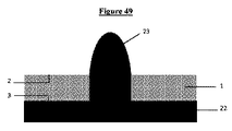
−少なくとも1つの穿孔(4)によって穴のあいた、上面(2)及び下面(3)を備える、非吸収性膜から成る支持体(1)と、
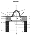
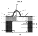
−上面(6)及び下面(7)を備え且つ少なくとも1つの突起(8)を備える3Dナノ構造多孔質膜(5)であって、前記少なくとも1つの突起が、外面(9)及び内面(10)を備え、且つ3Dナノ構造膜(5)の上面(6)の側上でレリーフ構造を形成し(図40)、
前記3Dナノ構造多孔質膜(5)の前記下面(7)が、前記支持体(1)の前記上面(2)に固定されて位置付けられる、
又は、3Dナノ構造膜(5)の前記上面(6)が、前記支持体(1)の前記下面(3)に固定されて位置付けられ、
前記3Dナノ構造多孔質膜(5)及び少なくとも1つの突起(8)が、2つの異なる細胞型の培養に適した材料から成る、3Dナノ構造多孔質膜(5)と、を含む、中央ユニット(105)と、
−ベース(106)であって、
前記中央ユニット(105)が、前記ベース(106)に統合され且つ前記ベース(106)によって全体を形成する、ベース(106)と(図39及び40)。
The present invention relates to a microfluidic cell culture chip comprising a central module (104) comprising:
-The central unit (105)
-A support (1) made of a non-absorbable membrane, having an upper surface (2) and a lower surface (3), perforated by at least one perforation (4).
-A 3D nanostructured porous membrane (5) having an upper surface (6) and a lower surface (7) and having at least one protrusion (8), wherein the at least one protrusion is an outer surface (9) and an inner surface (10). ), And a relief structure is formed on the side of the upper surface (6) of the 3D nanostructure film (5) (FIG. 40).
The lower surface (7) of the 3D nanostructured porous membrane (5) is fixedly positioned on the upper surface (2) of the support (1).
Alternatively, the upper surface (6) of the 3D nanostructured film (5) is fixedly positioned on the lower surface (3) of the support (1).
A central unit comprising the 3D nanostructured porous membrane (5) and a 3D nanostructured porous membrane (5) in which the at least one protrusion (8) is made of a material suitable for culturing two different cell types. (105) and
-Base (106)
The base (106) and (FIGS. 39 and 40), wherein the central unit (105) is integrated into the base (106) and formed entirely by the base (106).
「非吸収性膜」との表現は、膜が、物理的プロセスによっても水性溶媒における化学的プロセスによっても除去されないことがあることを意味する。 The expression "non-absorbable membrane" means that the membrane may not be removed by either a physical process or a chemical process in an aqueous solvent.
支持体に関する「穿孔」との表現は、一端から他へ支持体を通り抜ける開口部、つまり、下面と上面と間の支持体を通る開口部、を意味し、そのため、これらの2つの面間の連通を可能にさせる。 The expression "perforation" with respect to a support means an opening through the support from one end to the other, i.e., an opening through the support between the bottom and top surfaces, and thus between these two faces. Allows communication.
前記支持体のこの穿孔は、前記支持体を通る空き空間を生み出し、前記支持体の上面でのセクション及び前記支持体の下面でのセクションによって特徴付けられる。 This perforation of the support creates an empty space through the support and is characterized by a section on the upper surface of the support and a section on the lower surface of the support.
3Dナノ構造多孔質膜に関する「突起」との表現は、前記3Dナノ構造多孔質膜の上面の側上で、レリーフ構造を形成する突出した突部を意味する。 The expression "protrusion" with respect to the 3D nanostructured porous membrane means a protruding protrusion forming a relief structure on the upper surface side of the 3D nanostructured porous membrane.
3Dナノ構造多孔質膜に関する「多孔性」との表現は、前記膜が、前記膜の上面から下面へ伸びる、2と10nmとの間の直径の、互いに相互接続した連続した細孔を含むことを意味する。これらの細孔は、膜を通るガス交換、及び、小さな分子が培地に含まれること(成長因子、血清タンパク質、Ca2+,K+,Na+等のイオン等の細胞の生存率を確保する栄養素)を可能にさせる。これらの細孔はまた、阻害物質、又は抗癌性分子、小さなRNAs(例えば、緩衝RNAs)、ホルモン(例えば、ジヒドロテストステロン)等の薬理学的分子を通り抜けさせることを可能にさせる。 The expression "porosity" with respect to a 3D nanostructured porous membrane means that the membrane comprises continuous interconnected pores with diameters between 2 and 10 nm extending from the top to the bottom of the membrane. Means. These pores are nutrients that ensure the survival of cells such as gas exchange through the membrane and the inclusion of small molecules in the medium (growth factors, serum proteins, ions such as Ca 2+ , K + , Na +, etc.). ) Is possible. These pores also allow the passage of inhibitors or pharmacological molecules such as anticancer molecules, small RNAs (eg, buffered RNAs), hormones (eg, dihydrotestosterone).
多孔質膜に関する「3Dナノ構造」との表現は、前記多孔質膜の上面上の、3次元である、少なくとも1つのレリーフ構造の存在を意味し、前記構造のスケールは約1ナノメートルである。 The expression "3D nanostructure" for a porous membrane means the presence of at least one relief structure that is three-dimensional on the upper surface of the porous membrane, the scale of which is about 1 nanometer. ..
前記支持体と前記膜との間の接続のタイプを意味する「固定された」との表現は、化学結合、並びに、疎水性及び静電相互作用が、密封された接続によって凝集して前記膜と前記支持体とを結合するために、前記支持体と前記膜との間で確立されることを意味する。 The expression "fixed", which means the type of connection between the support and the membrane, means that the chemical bonds, as well as hydrophobic and electrostatic interactions, are aggregated by the sealed connection to the membrane. It means that it is established between the support and the membrane in order to bond the support and the support.
「ベース」との用語は、統合された前記ユニットである固体の部分を意味する。 The term "base" means a solid portion of said unit that is integrated.
ベースとユニットとの間の配置を特徴付けるために用いられる「全体を形成する」との表現は、ベース及びユニットが1つの単一の保持の一部を一緒に形成し、互いに分離されないことがあることを意味する。 The expression "form the whole" used to characterize the arrangement between the base and the unit may be that the base and the unit together form part of one single hold and are not separated from each other. Means that.
特定の実施形態によると、本発明は、以下を備える中央モジュール(104)を含むマイクロ流体細胞培養チップ関する:
−中央ユニット(105)であって、
−少なくとも1つの穿孔(4)によって穴のあいた、上面(2)及び下面(3)を備える、非吸収性膜から成る支持体(1)と、
−上面(6)及び下面(7)を備え且つ少なくとも1つの突起(8)を備える3Dナノ構造多孔質膜(5)であって、前記少なくとも1つの突起が、外面(9)及び内面(10)を備え、且つ3Dナノ構造膜(5)の上面(6)の側上でレリーフ構造を形成し(図40)、
前記3Dナノ構造膜(5)の前記下面(7)が、前記支持体(1)の前記上面(2)に固定されて位置付けられ、
前記3Dナノ構造多孔質膜(5)及び少なくとも1つの突起(8)が、2つの異なる細胞型の培養に適した材料から成る、3Dナノ構造多孔質膜(5)と、を含む、中央ユニット(105)と、
−ベース(106)であって、
前記中央ユニット(105)が、前記ベース(106)に統合され且つ前記ベース(106)によって全体を形成する、ベース(106)と(図39及び40)。
According to a particular embodiment, the invention relates to a microfluidic cell culture chip comprising a central module (104) comprising:
-The central unit (105)
-A support (1) made of a non-absorbable membrane, having an upper surface (2) and a lower surface (3), perforated by at least one perforation (4).
-A 3D nanostructured porous membrane (5) having an upper surface (6) and a lower surface (7) and having at least one protrusion (8), wherein the at least one protrusion is an outer surface (9) and an inner surface (10). ), And a relief structure is formed on the side of the upper surface (6) of the 3D nanostructure film (5) (FIG. 40).
The lower surface (7) of the 3D nanostructured film (5) is fixedly positioned on the upper surface (2) of the support (1).
A central unit comprising the 3D nanostructured porous membrane (5) and a 3D nanostructured porous membrane (5) in which the at least one protrusion (8) is made of a material suitable for culturing two different cell types. (105) and
-Base (106)
The base (106) and (FIGS. 39 and 40), wherein the central unit (105) is integrated into the base (106) and formed entirely by the base (106).
特定の実施形態によると、本発明は、以下を備える中央モジュール(104)を含むマイクロ流体細胞培養チップ関する:
−中央ユニット(105)であって、
−少なくとも1つの穿孔(4)によって穴のあいた、上面(2)及び下面(3)を備える、非吸収性膜から成る支持体(1)と、
−上面(6)及び下面(7)を備え且つ少なくとも1つの突起(8)を備える3Dナノ構造多孔質膜(5)であって、前記少なくとも1つの突起が、外面(9)及び内面(10)を備え、且つ3Dナノ構造膜(5)の上面(6)の側上でレリーフ構造を形成し、
前記3Dナノ構造膜(5)の前記上面(6)が、前記支持体(1)の前記下面(3)に固定されて位置付けられ、
前記3Dナノ構造多孔質膜(5)及び少なくとも1つの突起(8)が、2つの異なる細胞型の培養に適した材料から成る、3Dナノ構造多孔質膜(5)と、を含む、中央ユニット(105)と、
前記中央ユニット(105)が、前記ベース(106)に統合され且つ前記ベース(106)によって全体を形成する。
According to a particular embodiment, the invention relates to a microfluidic cell culture chip comprising a central module (104) comprising:
-The central unit (105)
-A support (1) made of a non-absorbable membrane, having an upper surface (2) and a lower surface (3), perforated by at least one perforation (4).
-A 3D nanostructured porous membrane (5) having an upper surface (6) and a lower surface (7) and having at least one protrusion (8), wherein the at least one protrusion is an outer surface (9) and an inner surface (10). ), And a relief structure is formed on the side of the upper surface (6) of the 3D nanostructured film (5).
The upper surface (6) of the 3D nanostructured film (5) is fixedly positioned on the lower surface (3) of the support (1).
A central unit comprising the 3D nanostructured porous membrane (5) and a 3D nanostructured porous membrane (5) in which the at least one protrusion (8) is made of a material suitable for culturing two different cell types. (105) and
The central unit (105) is integrated into the base (106) and formed entirely by the base (106).
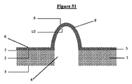
特定の実施形態によると、本発明は、前記マイクロ流体細胞培養チップのナノ構造多孔質膜の前記少なくとも1つの突起(8)が中空ドームの形状であり且つ円形ベース(13)を有するマイクロ流体細胞培養チップに関する。 According to a particular embodiment, the present invention is a microfluidic cell in which the at least one protrusion (8) of the nanostructured porous membrane of the microfluidic cell culture chip is in the shape of a hollow dome and has a circular base (13). Regarding culture chips.
突起の形状に関する「ドームの形状において」との表現は、前記突起が、前記支持体の上面の側上で凸部を形成する、円形ベースを有するアーチの形の、丸みを帯びた構造を有することを意味する。 The expression "in the shape of a dome" with respect to the shape of the protrusion has a rounded structure in the form of an arch with a circular base, wherein the protrusion forms a protrusion on the side of the upper surface of the support. Means that.
他の1つの実施形態では、前記突起は、前記支持体の上面の側の凸部を形成する、楕円ベースを有するアーチの形状における丸みを帯びた構造を有し得る。 In another embodiment, the protrusion may have a rounded structure in the form of an arch with an elliptical base that forms a protrusion on the upper surface side of the support.
「中空ドームの形状において」との表現は、前記突起がその下面の側上で前記3Dナノ構造膜の強化に対応するので、前記突起の内面が、自由体積を区切ることを意味し、そのため前記強化は、前記膜の下面の側上で凹部、それゆえ自由体積を形成する。 The expression "in the form of a hollow dome" means that the inner surface of the projection demarcates the free volume, as the projection corresponds to the reinforcement of the 3D nanostructured membrane on the side of its lower surface, and thus said. Reinforcement forms a recess, hence a free volume, on the side of the underside of the membrane.
中空ドームに関する「円形ベース」との表現は、前記突起の内面によって区切られ、その上にドームの形状における突起が置かれる自由下面を意味する。 The expression "circular base" with respect to a hollow dome means a free lower surface separated by the inner surface of the protrusion and on which the protrusion in the shape of a dome is placed.
特定の実施形態によると、本発明は、支持体の前記少なくとも1つの穿孔が、前記支持体の上面での円形セクション及び前記支持体の下面での円形セクションによって特徴付けられるマイクロ流体細胞培養チップに関する。 According to a particular embodiment, the invention relates to a microfluidic cell culture chip in which said at least one perforation of the support is characterized by a circular section on the upper surface of the support and a circular section on the lower surface of the support. ..
特定の実施形態によると、本発明は、支持体(1)の前記少なくとも1つの穿孔(4)が、
穿孔(4)の前記上部セクション(11)の中心を通り抜け且つ前記支持体(1)に垂直な軸(x)を有する、支持体(1)の上面(2)でのセクション(11)(穿孔の上部セクション)と、
穿孔(4)の前記下部セクション(12)の中心を通り抜け且つ前記支持体(1)に垂直な軸(w)を有する、支持体(1)の下面(3)でのセクション(12)(穿孔の下部セクション)と、を有し、
前記軸(x)及び(w)が組み合わされる、マイクロ流体細胞培養チップに関する。
According to a particular embodiment, the invention comprises the at least one perforation (4) of the support (1).
A section (11) (perforation) at the top surface (2) of the support (1) that passes through the center of the upper section (11) of the perforation (4) and has an axis (x) perpendicular to the support (1). Upper section) and
A section (12) (perforation) at the lower surface (3) of the support (1) that passes through the center of the lower section (12) of the perforation (4) and has an axis (w) perpendicular to the support (1). The lower section of) and has,
The present invention relates to a microfluidic cell culture chip in which the axes (x) and (w) are combined.
特定の実施形態によると、本発明は、支持体の下面での前記穿孔の円形セクションの直径d2が、支持体の上面での前記穿孔の円形セクションの直径d1以上であるマイクロ流体細胞培養チップに関する。 According to a particular embodiment, the present invention relates to a microfluidic cell culture chip in which the diameter d2 of the circular section of the perforation on the lower surface of the support is greater than or equal to the diameter d1 of the circular section of the perforation on the upper surface of the support. ..
特定の実施形態によると、本発明は、支持体(1)の前記少なくとも1つの穿孔(4)が、
直径d1(穿孔の上部直径d1)、及び、穿孔(4)の前記上部セクション(11)の中心を通り抜け且つ前記支持体(1)に垂直な軸(x)を有する、支持体(1)の上面での円形形状セクション(11)(穿孔の上部セクション)と、
直径d2(穿孔の下部直径d2)、及び、穿孔の前記下部セクションの中心を通り抜け且つ前記支持体(1)に垂直な軸(w)を有する、支持体(1)の下面(3)での円形形状セクション(12)(穿孔の下部セクション)と、を有し、
直径d1が500μm以下の値で10μm以上の値であり、好ましくは150μmの値であり、直径d2が500μm以下の値であり、好ましくは150μmの値であり、
直径d2の値が直径d1の値以上であり、
前記軸(x)及び(w)が組み合わされる(図1及び2)、マイクロ流体細胞培養チップに関する。
According to a particular embodiment, the invention comprises the at least one perforation (4) of the support (1).
Of the support (1) having a diameter d1 (upper diameter d1 of the perforation) and an axis (x) that passes through the center of the upper section (11) of the perforation (4) and has an axis (x) perpendicular to the support (1). A circular section (11) on the top surface (upper section of the perforation) and
At the lower surface (3) of the support (1) having a diameter d2 (lower diameter d2 of the perforation) and an axis (w) that passes through the center of the lower section of the perforation and has an axis (w) perpendicular to the support (1). With a circular shaped section (12) (lower section of the perforation),
The diameter d1 is 500 μm or less and 10 μm or more, preferably 150 μm, and the diameter d2 is 500 μm or less, preferably 150 μm.
The value of the diameter d2 is equal to or greater than the value of the diameter d1.
It relates to a microfluidic cell culture chip in which the axes (x) and (w) are combined (FIGS. 1 and 2).
特定の実施形態によると、本発明は、支持体の下面での前記穿孔の円形セクションの直径d2が、支持体の上面での前記穿孔の円形セクションの直径d1より大きいマイクロ流体細胞培養チップに関する。 According to certain embodiments, the present invention relates to a microfluidic cell culture chip in which the diameter d2 of the circular section of the perforation on the lower surface of the support is greater than the diameter d1 of the circular section of the perforation on the upper surface of the support.
特定の実施形態によると、本発明は、支持体の下面での前記穿孔の円形セクションの直径d2が、支持体の上面での前記穿孔の円形セクションの直径d1より大きく、比率(d1の値/d2の値)が0.3の値から1未満の値である、マイクロ流体細胞培養チップに関する。 According to certain embodiments, the present invention has a ratio (value of d1) such that the diameter d2 of the circular section of the perforation on the lower surface of the support is greater than the diameter d1 of the circular section of the perforation on the upper surface of the support. It relates to a microfluidic cell culture chip in which the value of d2) is from a value of 0.3 to less than 1.
特定の実施形態によると、本発明は、支持体の下面での前記穿孔の円形セクションの直径d2が、支持体の上面での前記穿孔の円形セクションの直径d1より大きく、前記支持体の前記穿孔が円錐台の形状であるマイクロ流体細胞培養チップに関する。 According to certain embodiments, the present invention has the diameter d2 of the circular section of the perforation on the lower surface of the support larger than the diameter d1 of the circular section of the perforation on the upper surface of the support and the perforation of the support. Relates to a microfluidic cell culture chip in the shape of a truncated cone.
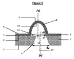
特定の実施形態によると、本発明は、前記少なくとも1つの穿孔(4)の上部直径d1の値が前記少なくとも1つの穿孔(4)の下部直径d2の値未満であり、前記穿孔(4)が円錐台形状である(図2)マイクロ流体細胞培養チップに関する。 According to a particular embodiment, in the present invention, the value of the upper diameter d1 of the at least one perforation (4) is less than the value of the lower diameter d2 of the at least one perforation (4), wherein the perforation (4) is. It relates to a microfluidic cell culture chip having a truncated cone shape (Fig. 2).
特定の実施形態によると、本発明は、支持体の下面での前記穿孔の円形セクションの直径d2が、支持体の上面での前記穿孔の円形セクションの直径d1に等しいマイクロ流体細胞培養チップに関する。 According to a particular embodiment, the present invention relates to a microfluidic cell culture chip in which the diameter d2 of the circular section of the perforation on the lower surface of the support is equal to the diameter d1 of the circular section of the perforation on the upper surface of the support.
特定の実施形態によると、本発明は、支持体の下面での前記穿孔の円形セクションの直径d2が、支持体の上面での前記穿孔の円形セクションの直径d1に等しく、前記支持体の前記穿孔が円筒形状である、マイクロ流体細胞培養チップに関する。 According to certain embodiments, the present invention has the diameter d2 of the circular section of the perforation on the lower surface of the support equal to the diameter d1 of the circular section of the perforation on the upper surface of the support and the perforation of the support. Relates to a microfluidic cell culture chip, which has a cylindrical shape.
この実施形態では、そのため、前記支持体の穿孔は、規則的な形状であり、つまり、そのセクションの内のすべて、の直径は等しい長さであり、前記セクションは円形形状である。 In this embodiment, therefore, the perforations in the support are of regular shape, i.e., the diameters of all within the section are of equal length, and the section is of circular shape.
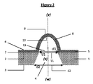
特定の実施形態によると、本発明は、前記少なくとも1つの穿孔(4)の上部直径d1の値が前記少なくとも1つの穿孔(4)の下部直径d2の値に等しく、前記穿孔(4)が円筒形状である(図1)マイクロ流体細胞培養チップに関する。 According to a particular embodiment, in the present invention, the value of the upper diameter d1 of the at least one perforation (4) is equal to the value of the lower diameter d2 of the at least one perforation (4), and the perforation (4) is cylindrical. It relates to a microfluidic cell culture chip which is in shape (Fig. 1).
特定の実施形態によると、本発明は、前記突起(8)が円形ベース(13)を有し、直径d3を有し(突起の円形ベースの直径d3)、突起(8)の前記直径d3が10μmの値から500μmの値である、マイクロ流体細胞培養チップに関する。 According to a particular embodiment, in the present invention, the protrusion (8) has a circular base (13), has a diameter d3 (diameter d3 of the circular base of the protrusion), and the diameter d3 of the protrusion (8). With respect to microfluidic cell culture chips ranging in value from 10 μm to 500 μm.
特定の実施形態によると、本発明は、前記少なくとも1つの突起(8)の直径d3の値が、前記少なくとも1つの穿孔(4)の上部直径d1の値に等しい(図1及び2)マイクロ流体細胞培養チップに関する。 According to a particular embodiment, the invention equals the value of the diameter d3 of the at least one protrusion (8) to the value of the upper diameter d1 of the at least one perforation (4) (FIGS. 1 and 2). Regarding cell culture chips.
特定の実施形態によると、本発明は、前記少なくとも1つの突起(8)の直径d3の値が、前記少なくとも1つの穿孔の上部直径d1の値に等しく、前記少なくとも1つの穿孔(4)の下部直径d2の値に等しい(図1及び3)マイクロ流体細胞培養チップに関する。 According to a particular embodiment, the present invention has the value of diameter d3 of the at least one protrusion (8) equal to the value of the upper diameter d1 of the at least one perforation and the lower part of the at least one perforation (4). It relates to a microfluidic cell culture chip equal to the value of diameter d2 (FIGS. 1 and 3).
特定の実施形態によると、本発明は、前記少なくとも1つの突起(8)の直径d3の値が、前記少なくとも1つの穿孔(4)の上部直径d1の値より大きい(図4、5及び6)マイクロ流体細胞培養チップに関する。 According to a particular embodiment, the present invention has a value of diameter d3 of the at least one protrusion (8) greater than a value of the upper diameter d1 of the at least one perforation (4) (FIGS. 4, 5 and 6). Regarding microfluidic cell culture chips.
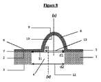
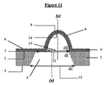
特定の実施形態によると、本発明は、前記少なくとも1つの突起(8)の直径d3の値が、前記少なくとも1つの穿孔(4)の上部直径d1の値未満である(図7、8、9、10及び11)マイクロ流体細胞培養チップに関する。 According to a particular embodiment, the present invention has a value of diameter d3 of the at least one protrusion (8) less than the value of the upper diameter d1 of the at least one perforation (4) (FIGS. 7, 8, 9). 10, 11) Regarding microfluidic cell culture chips.
特定の実施形態によると、本発明は、前記少なくとも1つの突起(8)の前記内面(10)が全体において又は一部において、前記支持体(1)の前記少なくとも1つの穿孔(4)に面しているマイクロ流体細胞培養チップに関する。 According to a particular embodiment, the present invention confronts the at least one perforation (4) of the support (1) with the inner surface (10) of the at least one protrusion (8) in whole or in part. Regarding microfluidic cell culture chips.
少なくとも1つの突起及び少なくとも1つの穿孔によって穴のあいた支持体を備える3Dナノ構造膜は、前記突起の内面が全体において又は一部において、支持体の上面で前記穿孔の円形セクションに面しているように、位置付けられる。 A 3D nanostructured membrane comprising a support perforated by at least one protrusion and at least one perforation faces the circular section of the perforation on the upper surface of the support, with the inner surface of the protrusion in whole or in part. It is positioned as such.
特定の実施形態によると、本発明は、前記少なくとも1つの突起(8)の前記内面(10)が全体において、前記支持体(1)の前記少なくとも1つの穿孔(4)に面しているマイクロ流体細胞培養チップに関する:
−前記少なくとも1つの穿孔(4)の上部直径d1の値が前記少なくとも1つの突起(4)の直径d3の値以上であり、前記円形ベース(13)の中心を通り抜け且つ前記支持体(1)に垂直な軸(y)と前記穿孔(4)の上部セクション(11)の中心を通り抜け且つ前記支持体(1)に垂直な軸(x)とが組み合わされるとき(図1、2、7及び9);又は、
−前記少なくとも1つの穿孔(4)の上部直径d1の値が前記少なくとも1つの突起(8)の直径d3の値より大きく、前記円形ベース(13)の中心を通り抜け且つ前記支持体(1)に垂直な軸(y)と前記穿孔(4)の上部セクション(11)の中心を通り抜け且つ前記支持体(1)に垂直な軸(x)とが[(d1の値−d3の値)/2]以下の値の距離によって互いに異なるとき(図8及び11)。
According to a particular embodiment, the invention is a micron in which the inner surface (10) of the at least one protrusion (8) faces the at least one perforation (4) of the support (1) as a whole. Regarding fluid cell culture chips:
-The value of the upper diameter d1 of the at least one perforation (4) is greater than or equal to the value of the diameter d3 of the at least one protrusion (4), passing through the center of the circular base (13) and the support (1). When the axis (y) perpendicular to the axis (y) and the axis (x) passing through the center of the upper section (11) of the perforation (4) and perpendicular to the support (1) are combined (FIGS. 1, 2, 7 and). 9); or
-The value of the upper diameter d1 of the at least one perforation (4) is greater than the value of the diameter d3 of the at least one protrusion (8), passing through the center of the circular base (13) and into the support (1). The vertical axis (y) and the axis (x) passing through the center of the upper section (11) of the perforation (4) and perpendicular to the support (1) are [(value of d1 − value of d3) / 2). ] When they differ from each other depending on the distance of the following values (FIGS. 8 and 11).
軸(x)及び(y)を特徴付けるために用いられる「組み合わされる」との用語は、これらの2つの軸間の距離がゼロに等しいことを意味する。 The term "combined" used to characterize the axes (x) and (y) means that the distance between these two axes is equal to zero.
軸(x)及び(y)を特徴付けるために用いられる「異なる」との用語は、これらの2つの軸間の距離が厳密にゼロより大きいことを意味する。 The term "different" used to characterize the axes (x) and (y) means that the distance between these two axes is exactly greater than zero.
特定の実施形態によると、本発明は、前記少なくとも1つの突起(8)の前記内面(10)が部分的に、前記支持体(1)の前記少なくとも1つの穿孔(4)に面しているマイクロ流体細胞培養チップに関する:
−前記少なくとも1つの穿孔(4)の上部直径d1の値が前記少なくとも1つの突起(8)の直径d3の値未満であり、前記円形ベース(13)の中心を通り抜け且つ前記支持体(1)に垂直な軸(y)と前記穿孔(4)の上部セクション(11)の中心を通り抜け且つ前記支持体(1)に垂直な軸(x)とが組み合わされるとき(図6);又は、
−前記穿孔(4)の上部直径d1の値が前記突起(8)の直径d3の値以下であり、前記円形ベース(13)の中心を通り抜け且つ前記支持体(1)に垂直な軸(y)と前記穿孔(4)の上部セクション(11)の中心を通り抜け且つ前記支持体(1)に垂直な軸(x)とがd3の値未満の値の距離によって互いに異なるとき(図3、4及び5);又は、
−前記穿孔(4)の上部直径d1の値が前記突起(8)の直径d3の値より大きく、前記円形ベース(13)の中心を通り抜け且つ前記支持体(1)に垂直な軸(y)と前記穿孔(4)の上部セクション(11)の中心を通り抜け且つ前記支持体(1)に垂直な軸(x)とが[[d1の値+d3の値]/2]未満の値で[(d1の値−d3の値)/2]より大きい値の距離によって互いに異なるとき(図10)。
According to a particular embodiment, the invention partially faces the at least one perforation (4) of the support (1) with the inner surface (10) of the at least one protrusion (8). Regarding microfluidic cell culture chips:
-The value of the upper diameter d1 of the at least one perforation (4) is less than the value of the diameter d3 of the at least one protrusion (8), passes through the center of the circular base (13) and the support (1). When the axis (y) perpendicular to the axis (y) and the axis (x) passing through the center of the upper section (11) of the perforation (4) and perpendicular to the support (1) are combined (FIG. 6); or
-The value of the upper diameter d1 of the perforation (4) is equal to or less than the value of the diameter d3 of the protrusion (8), passes through the center of the circular base (13), and has an axis (y) perpendicular to the support (1). ) And the axis (x) passing through the center of the upper section (11) of the perforation (4) and perpendicular to the support (1) differing from each other depending on the distance of a value less than the value of d3 (FIGS. 3, 4). And 5); or
-The value of the upper diameter d1 of the perforation (4) is larger than the value of the diameter d3 of the protrusion (8), the axis (y) passing through the center of the circular base (13) and perpendicular to the support (1). And the axis (x) passing through the center of the upper section (11) of the perforation (4) and perpendicular to the support (1) is less than [[value of d1 + value of d3] / 2] [(). When the values differ from each other depending on the distance of a value larger than (d1 value − d3 value) / 2] (FIG. 10).
特定の実施形態によると、本発明は、突起(4)が斜めの変形を有するマイクロ流体細胞培養チップに関し、前記斜めの変形が、
−前記支持体(1)の上面(2)で前記突起(8)によって及び前記突起(8)の頂部によって区切られた、直径d3の円形ベース(13)の中心を通り抜ける軸(z)と、
−前記円形ベース(13)の中心を通り抜け且つ前記支持体(1)に垂直な軸(y)と、間で形成される角度αによって画定される(図12)。
According to a particular embodiment, the present invention relates to a microfluidic cell culture chip in which the protrusion (4) has an oblique deformation.
-A shaft (z) passing through the center of a circular base (13) having a diameter of d3, separated by the protrusion (8) on the upper surface (2) of the support (1) and by the top of the protrusion (8).
-Defined by an angle α formed between an axis (y) that passes through the center of the circular base (13) and is perpendicular to the support (1) (FIG. 12).
特定の実施形態によると、本発明は、軸(y)と軸(z)との間で形成された角度αが0と45°との間であるマイクロ流体細胞培養チップに関する。 According to a particular embodiment, the invention relates to a microfluidic cell culture chip in which the angle α formed between the axes (y) and the axes (z) is between 0 and 45 °.
特定の実施形態によると、本発明は、軸(y)と軸(z)との間で形成された角度αが0と60°との間であるマイクロ流体細胞培養チップに関する。 According to a particular embodiment, the invention relates to a microfluidic cell culture chip in which the angle α formed between the axes (y) and the axes (z) is between 0 and 60 °.
軸(y)と軸(z)との間で形成される角度αが45°より大きい場合、突起の傾きは、分泌物の回収を部分的に妨げる。角度αを取り得る最大理論値は90°であるが、この実施形態では、突起は、前記3Dナノ構造膜の上面に沿って完全に折りたたまれ、分泌物の回収は妨げられる。 If the angle α formed between the axis (y) and the axis (z) is greater than 45 °, the inclination of the protrusions partially impedes the recovery of secretions. The maximum theoretical value for which the angle α can be taken is 90 °, but in this embodiment the protrusions are completely folded along the upper surface of the 3D nanostructured membrane, hindering the recovery of secretions.
特定の実施形態によると、本発明は、前記突起(8)の外面(9)が前記外面上で少なくとも1つの接着細胞を支え、前記突起(8)の内面(10)が前記内面(10)上で少なくとも1つの接着細胞を支え、少なくとも2つの細胞が2つの異なる細胞型に属する、マイクロ流体細胞培養チップに関する。 According to a particular embodiment, in the present invention, the outer surface (9) of the protrusion (8) supports at least one adherent cell on the outer surface, and the inner surface (10) of the protrusion (8) is the inner surface (10). It relates to a microfluidic cell culture chip that supports at least one adherent cell above and at least two cells belong to two different cell types.
「接着細胞」との用語は、その成長が支持体への接着を必要とし、それに関して前記支持体への脱離が機械的又は酵素処理(例えば、トリプシンによる)を必要とする任意のタイプの細胞を意味する。 The term "adhesive cell" refers to any type of cell whose growth requires adhesion to a support, with respect to which detachment to said support requires mechanical or enzymatic treatment (eg, by trypsin). Means a cell.
「異なる細胞型」との用語は、異なる性質又は機能の、又は異なる組織に由来する細胞型を意味するために用いられる。 The term "different cell type" is used to mean a cell type of a different nature or function, or derived from a different tissue.
特定の実施形態によると、本発明は、前記外面上の前記接着細胞が間質細胞であり、前記内面上の前記接着細胞が上皮細胞であるマイクロ流体細胞培養チップに関する。 According to a particular embodiment, the invention relates to a microfluidic cell culture chip in which the adherent cells on the outer surface are stromal cells and the adherent cells on the inner surface are epithelial cells.
特定の実施形態によると、本発明は、前記外面(9)上の前記少なくとも1つの接着細胞が間質細胞、より具体的には線維芽細胞であり、前記内面(10)上の前記少なくとも1つの接着細胞が上皮細胞であるマイクロ流体細胞培養チップに関する。 According to a particular embodiment, the invention is that the at least one adherent cell on the outer surface (9) is a stromal cell, more specifically a fibroblast, and the at least 1 on the inner surface (10). It relates to a microfluidic cell culture chip in which one adherent cell is an epithelial cell.
特定の実施形態によると、本発明は、前記外面上の前記接着細胞が上皮細胞であり、前記内面上の前記接着細胞が間質細胞であるマイクロ流体細胞培養チップに関する。 According to a particular embodiment, the invention relates to a microfluidic cell culture chip in which the adherent cells on the outer surface are epithelial cells and the adherent cells on the inner surface are stromal cells.
上皮細胞は、前立腺、膀胱若しくは腎臓非腫瘍形成性市販の細胞株、又は市販の初代培養物であり得る。 Epithelial cells can be prostate, bladder or kidney nontumorogenic commercial cell lines, or commercial primary cultures.
間質細胞は、線維芽細胞(市販の初代培養物若しくは株)、間充織細胞(市販の培養若しくは株)、又は、内皮細胞等の他の間質細胞であり得る。 The stromal cells can be fibroblasts (commercially available primary cultures or strains), interstitial cells (commercially available cultures or strains), or other stromal cells such as endothelial cells.
前記突起の内面及び外面上に培養される2つの細胞型は、「中立」又は正常細胞と呼ばれる。つまり、それらは非腫瘍形成性である。 The two cell types cultured on the inner and outer surfaces of the process are referred to as "neutral" or normal cells. That is, they are non-tumorogenic.
特定の実施形態によると、本発明は、前記突起(8)の外面(9)が合流の段階で第1のセットの接着細胞を支え、前記突起(8)の内面(10)が合流の段階で第2のセットの接着細胞を支え、第1の及び第2のセットの接着細胞の細胞が2つの異なる細胞型に属する、マイクロ流体細胞培養チップに関する(図13)。 According to a particular embodiment, the invention supports the first set of adherent cells at the stage of confluence of the outer surface (9) of the projection (8) and the stage of confluence of the inner surface (10) of the projection (8). With respect to a microfluidic cell culture chip that supports a second set of adherent cells and the cells of the first and second sets of adherent cells belong to two different cell types (FIG. 13).
特定の実施形態によると、本発明は、前記突起(8)の外面(9)が、有利には合流の段階で、第1のセットの接着細胞を支え、前記第1のセットは間質細胞の、より具体的には線維芽細胞のセットであり、前記突起(8)の内面(10)は合流の段階で第2のセットの接着細胞を支え、前記第2のセットが上皮細胞のセットである、マイクロ流体細胞培養チップに関する(図52)。 According to a particular embodiment, the invention supports a first set of adherent cells in which the outer surface (9) of the projections (8) advantageously joins, with the first set being stromal cells. More specifically, the inner surface (10) of the projection (8) supports a second set of adherent cells at the confluence stage, and the second set is a set of epithelial cells. The present invention relates to a microfluidic cell culture chip (FIG. 52).
特定の実施形態によると、本発明は、前記突起(8)の外面(9)が、第1のセットの接着細胞を支え、前記第1のセットは間質細胞の、より具体的には線維芽細胞のセットであり、前記突起(8)の内面(10)は合流の段階で第2のセットの接着細胞を支え、前記第2のセットが上皮細胞のセットである、マイクロ流体細胞培養チップに関する。 According to a particular embodiment, in the present invention, the outer surface (9) of the projection (8) supports a first set of adherent cells, the first set of which are stromal cells, more specifically fibers. A microfluidic cell culture chip that is a set of blast cells, the inner surface (10) of the projection (8) supporting a second set of adherent cells at the confluence stage, the second set being a set of epithelial cells. Regarding.
特定の実施形態によると、本発明は、突起の外面及び内面が、これらの表面上に細胞を導入する前、つまり細胞培養前に、細胞外マトリクス(ECM)調製(Matrigel(登録商標)、コラーゲン、フィブロネクチン、ヒアルロン酸)によって覆われるマイクロ流体細胞培養チップに関する。より具体的には、前記ECM調製は、Matrigel(登録商標)又はMatrigel(登録商標)/コラーゲン混合物から成る。 According to certain embodiments, the present invention provides extracellular matrix (ECM) preparation (Matrixel®, collagen) prior to the introduction of cells onto these surfaces, i.e., cell culture, by the outer and inner surfaces of the projections. , Fibronectin, hyaluronic acid) to cover microfluidic cell culture chips. More specifically, the ECM preparation comprises a Matrix® or Matrix® / collagen mixture.
特定の実施形態によると、本発明は、前記3Dナノ構造多孔質膜が2から300nm、より具体的には30nmの厚さを有するマイクロ流体細胞培養チップに関する。 According to a particular embodiment, the invention relates to a microfluidic cell culture chip in which the 3D nanostructured porous membrane has a thickness of 2 to 300 nm, more specifically 30 nm.
特定の実施形態によると、本発明は、前記3Dナノ構造多孔質膜が2から300nmの厚さを有するマイクロ流体細胞培養チップに関する。 According to a particular embodiment, the invention relates to a microfluidic cell culture chip in which the 3D nanostructured porous membrane has a thickness of 2 to 300 nm.
特定の実施形態によると、本発明は、前記3Dナノ構造多孔質膜が30nmの厚さを有するマイクロ流体細胞培養チップに関する。 According to a particular embodiment, the invention relates to a microfluidic cell culture chip in which the 3D nanostructured porous membrane has a thickness of 30 nm.
突起はその円形形状ベースでセクションを有し、このセクションの表面は、半径に従って計算され得る。 The protrusion has a section on its circular shape base, and the surface of this section can be calculated according to the radius.
特定の実施形態によると、本発明は、中空ドームの形状における前記突起が1から600μm、より具体的には1から300μm、より具体的には50から300μm、より具体的には50μmの高さを、及び、78.5μm2から200000μm2、より具体的には2000から70000μm2、さらにより具体的には17500μm2の、さらにより具体的には7850μm2のドームのベースによって区切られた表面を有する、マイクロ流体細胞培養チップに関する。 According to certain embodiments, the present invention has the protrusions in the shape of a hollow dome having a height of 1 to 600 μm, more specifically 1 to 300 μm, more specifically 50 to 300 μm, more specifically 50 μm. And, more specifically, the surface separated by the base of the dome of 78.5 μm 2 to 200,000 μm 2 , more specifically 2000 to 70,000 μm 2 , more specifically 17500 μm 2 , and even more specifically 7850 μm 2. It relates to a microfluidic cell culture chip having.
「高さ」との用語は、突起の頂部の中心と直径d3の開口部の中心との間の距離を意味する。 The term "height" means the distance between the center of the apex of the protrusion and the center of the opening of diameter d3.
特定の実施形態によると、本発明は、前記支持体が同一形状及び寸法の少なくとも2つの穿孔を備え、前記3Dナノ構造多孔質膜が同一形状及び寸法の少なくとも2つの突起を備え、穿孔の数が突起の数に等しい、マイクロ流体細胞培養チップに関する。 According to certain embodiments, the present invention comprises the support having at least two perforations of the same shape and size, and the 3D nanostructured porous membrane having at least two protrusions of the same shape and size, the number of perforations. With respect to a microfluidic cell culture chip, where is equal to the number of protrusions.
前記膜が少なくとも2つの突起を備えるとき、距離は、これらの少なくとも2つの突起間で画定されなくてはならない。 When the membrane comprises at least two protrusions, the distance must be defined between these at least two protrusions.
「2つの隣接する突起間の距離」との表現の定義は、2つの隣接する突起の前記3Dナノ構造膜の外面の交差によって形成される円周上にそれぞれ位置し、且つ、2つの隣接する突起の前記円周上にそれぞれ位置する点の対の間のすべての可能な距離の内の最短距離を形成する、2つの点の間の距離であるとしなくてはならない(図32)。 The definition of "distance between two adjacent projections" is defined as each located on the circumference formed by the intersection of the outer surfaces of the 3D nanostructured membranes of the two adjacent projections, and two adjacent projections. It must be the distance between the two points forming the shortest of all possible distances between the pairs of points located on the circumference of the protrusion (FIG. 32).
前記膜が少なくとも2つの突起を備えるとき、これらは適切な距離によって分離されなくてはならない。 When the membrane comprises at least two protrusions, they must be separated by an appropriate distance.
特定の実施形態によると、本発明は、2つの隣接する突起間の距離が値lであり、前記値lが10から100μmである、マイクロ流体細胞培養チップに関する。 According to a particular embodiment, the present invention relates to a microfluidic cell culture chip in which the distance between two adjacent projections is a value l, said value l being 10 to 100 μm.
特定の実施形態によると、本発明は、2つの隣接する突起間の距離が値lであり、前記値lが10から100μm、より具体的には50から100μmである、マイクロ流体細胞培養チップに関する。 According to a particular embodiment, the present invention relates to a microfluidic cell culture chip in which the distance between two adjacent projections is a value l, said value l being 10 to 100 μm, more specifically 50 to 100 μm. ..
特定の実施形態によると、本発明は、2つの隣接する突起間の距離が値lであり、前記値lが50から100μmである、マイクロ流体細胞培養チップに関する。 According to a particular embodiment, the present invention relates to a microfluidic cell culture chip in which the distance between two adjacent projections is a value l, said value l being 50 to 100 μm.
各々の以下の段落では、「2つの隣接する突起間の距離」との表現は、上記で与えられた定義によって置き換えられ得る。 In each of the following paragraphs, the expression "distance between two adjacent protrusions" can be replaced by the definition given above.
特定の実施形態によると、本発明は、前記支持体が少なくとも2つの穿孔を備え、前記ナノ構造多孔質膜が少なくとも2つの突起を備える、マイクロ流体細胞培養チップに関する。例えば比率 According to a particular embodiment, the invention relates to a microfluidic cell culture chip, wherein the support comprises at least two perforations and the nanostructured porous membrane comprises at least two protrusions. For example ratio

は1から Is from 1
まで変化し、lは2つの隣接する突起間の距離の値であり、直径d1が500μm以下の値で10μm以上の値であり、直径d2が500μm以下且つ10μm以上の値である。 L is the value of the distance between two adjacent protrusions, the diameter d1 is a value of 500 μm or less and 10 μm or more, and the diameter d2 is a value of 500 μm or less and 10 μm or more.
そのため、支持体の下面での前記穿孔の下部直径d2は常に、支持体の上面での前記穿孔の上部直径d1以上である。 Therefore, the lower diameter d2 of the perforation on the lower surface of the support is always greater than or equal to the upper diameter d1 of the perforation on the upper surface of the support.
特定の実施形態によると、本発明は、前記3Dナノ構造多孔質膜が1cm2の中央ユニットの表面に関して1から100個の突起を備えるマイクロ流体細胞培養チップに関する。 According to a particular embodiment, the invention relates to a microfluidic cell culture chip in which the 3D nanostructured porous membrane comprises 1 to 100 protrusions on the surface of a 1 cm 2 central unit.
特定の実施形態によると、本発明は、前記3Dナノ構造膜が、以下の式に等しい、1cm2の中央ユニットの表面に関する最大数の突起を備えるマイクロ流体細胞培養チップに関し、 According to a particular embodiment, the present invention relates to a microfluidic cell culture chip in which the 3D nanostructured membrane comprises the maximum number of protrusions on the surface of a 1 cm 2 central unit, which is equivalent to the following equation.
lが2つの隣接する突起間の距離であり、前記値lが10から100μm、より具体的には50から100μmであり、
d3が前記突起の直径である。
l is the distance between two adjacent protrusions, and the value l is 10 to 100 μm, more specifically 50 to 100 μm.
d3 is the diameter of the protrusion.
3Dナノ構造多孔質膜は、層の連続性が少なくとも2つの層から適用されると理解される、1から150個までの高分子電解質の多数の連続する層から成る。 A 3D nanostructured porous membrane consists of a large number of contiguous layers of polyelectrolytes from 1 to 150, where layer continuity is understood to apply from at least two layers.
層の数は、突起の機械的強度を変化させることを可能にさせる。実際、層の数の増加が大きいほど、突起の機械的抵抗の増加は大きくなり、これらの外面及び内面上で細胞培養を支えつつ、それのいずれかの側面上で(例えば培地の)流れに抵抗することによって、それらはその外形を保ち得るようになる。 The number of layers makes it possible to vary the mechanical strength of the protrusions. In fact, the greater the increase in the number of layers, the greater the increase in mechanical resistance of the protrusions, supporting cell culture on these outer and inner surfaces while flowing on any aspect of it (eg, in the medium). By resisting, they are able to retain their shape.
特定の実施形態によると、本発明は、高分子電解質の連続する層の数が1から150、特に15であるマイクロ流体細胞培養チップに関する。 According to certain embodiments, the present invention relates to microfluidic cell culture chips in which the number of contiguous layers of polyelectrolyte is 1 to 150, particularly 15.
3Dナノ構造多孔質膜を構成するための高分子電解質の使用は、その上に接着細胞が組織において付着されるようになる基底膜を真似るための生体適合性且つ機能性代替物を提供する。 The use of polyelectrolytes to construct 3D nanostructured porous membranes provides a biocompatible and functional alternative for mimicking the basement membrane on which adherent cells become attached in tissues.
3Dナノ構造多孔質膜は、高分子電解質の層から成り得る。 The 3D nanostructured porous membrane can consist of a layer of polyelectrolyte.
特定の実施形態によると、本発明は、3Dナノ構造多孔質膜がポリ(4−スチレンスルホン酸ナトリウム)(PSS)、ポリ(エチレンイミン)、ポリ(ジアリルジメチルアンモニウムクロライド)、ポリ(アクリルアミド−co−ジアリルジメチルアンモニウムクロライド)、ジアリルジメチルアンモニウムクロライド、ポリ(アリルアミン塩酸塩)(PAH)、ポリアネトールスルホン酸、ポリアクリル酸、ポリ(スチレン−alt−マレイン酸)、ポリビニル硫酸塩、ポリビニルスルホン酸、ポリ(2−アクリルアミド−2−メチル−1−プロパンスルホン酸)、ポリ(2−アクリルアミド−2−メチル−1−プロパンスルホン−co−アクリロニトリル)酸、ポリ(4−スチレンスルホン酸)、ポリ(4−スチレンスルホン酸−co−マレイン酸)、水和4−スチレンスルホン酸ナトリウム塩の内から選択される高分子電解質の層から成る、マイクロ流体細胞培養チップに関する。 According to certain embodiments, the present invention comprises a 3D nanostructured porous membrane of poly (sodium 4-styrene sulfonate) (PSS), poly (ethyleneimine), poly (diallyldimethylammonium chloride), poly (acrylamide-co). -Diallyldimethylammonium chloride), diallyldimethylammonium chloride, poly (allylamine hydrochloride) (PAH), polyanator sulfonic acid, polyacrylic acid, poly (styrene-alt-maleic acid), polyvinyl sulfate, polyvinyl sulfonic acid, poly (2-acrylamide-2-methyl-1-propanesulfonic acid), poly (2-acrylamide-2-methyl-1-propanesulfon-co-acrylonitrile) acid, poly (4-styrenesulfonic acid), poly (4-styrenesulfonic acid), poly (4-styrenesulfonic acid) Containing a microfluidic cell culture chip comprising a layer of polymer electrolyte selected from styrene sulfonic acid-co-maleic acid), hydrated 4-styrene sulfonic acid sodium salt.
3Dナノ構造多孔質膜は、高分子電解質の少なくとも2つの連続する層から成り得る。 The 3D nanostructured porous membrane can consist of at least two consecutive layers of polyelectrolyte.
前記膜が少なくとも2つの層を備えるとき、この膜の構造は、層ごとに、必要不可欠である。 When the membrane comprises at least two layers, the structure of the membrane is essential for each layer.
前記3Dナノ構造多孔質膜の不可欠な部分である少なくとも1つの突起、前記3Dナノ構造多孔質膜の構成は、前記少なくとも1つの突起の構成と同一であろう。 The configuration of at least one protrusion, which is an integral part of the 3D nanostructured porous membrane, the 3D nanostructured porous membrane will be identical to the configuration of the at least one protrusion.
特定の実施形態によると、本発明は、3Dナノ構造多孔質膜がポリ(4−スチレンスルホン酸ナトリウム)(PSS)、ポリ(エチレンイミン)、ポリ(ジアリルジメチルアンモニウムクロライド)、ポリ(アクリルアミド−co−ジアリルジメチルアンモニウムクロライド)、ジアリルジメチルアンモニウムクロライド、ポリ(アリルアミン塩酸塩)(PAH)、ポリアネトールスルホン酸、ポリアクリル酸、ポリ(スチレン−alt−マレイン酸)、ポリビニル硫酸塩、ポリビニルスルホン酸、ポリ(2−アクリルアミド−2−メチル−1−プロパンスルホン酸)、ポリ(2−アクリルアミド−2−メチル−1−プロパンスルホン−co−アクリロニトリル)酸、ポリ(4−スチレンスルホン酸)、ポリ(4−スチレンスルホン酸−co−マレイン酸)、水和4−スチレンスルホン酸ナトリウム塩の内から選択される高分子電解質の連続する層から成る、マイクロ流体細胞培養チップに関する。 According to certain embodiments, the present invention comprises a 3D nanostructured porous membrane of poly (sodium 4-styrene sulfonate) (PSS), poly (ethyleneimine), poly (diallyldimethylammonium chloride), poly (acrylamide-co). -Diallyldimethylammonium chloride), diallyldimethylammonium chloride, poly (allylamine hydrochloride) (PAH), polyanator sulfonic acid, polyacrylic acid, poly (styrene-alt-maleic acid), polyvinyl sulfate, polyvinyl sulfonic acid, poly (2-acrylamide-2-methyl-1-propanesulfonic acid), poly (2-acrylamide-2-methyl-1-propanesulfon-co-acrylonitrile) acid, poly (4-styrenesulfonic acid), poly (4-styrenesulfonic acid), poly (4-styrenesulfonic acid) Containing a microfluidic cell culture chip comprising a continuous layer of polymer electrolyte selected from styrene sulfonic acid-co-maleic acid), hydrated 4-styrene sulfonic acid sodium salt.
前記膜が少なくとも2つの連続する層を備えるとき、前記層は、異なる性質の少なくとも2つの高分子電解質に対応し得る:少なくとも1つの負に帯電した高分子電解質及び少なくとも1つの正に帯電した高分子電解質。 When the membrane comprises at least two consecutive layers, the layers may correspond to at least two polyelectrolytes of different properties: at least one negatively charged polyelectrolyte and at least one positively charged polyelectrolyte. Molecular electrolyte.
この場合では、この膜の構造は、層ごとに、正に帯電した高分子電解質層が負に帯電した高分子電解質層と交互になるようにされなくてはならない。 In this case, the structure of this membrane must be such that, for each layer, the positively charged polyelectrolyte layer alternates with the negatively charged polyelectrolyte layer.
そのため、膜は、正に帯電した高分子電解質層と負に帯電した高分子電解質層との間の静電相互作用のため高度に凝集性である。これは、約1キロパスカルであるヤング率を有する膜を得ることを可能にさせる。 Therefore, the membrane is highly aggregated due to the electrostatic interaction between the positively charged polyelectrolyte layer and the negatively charged polyelectrolyte layer. This makes it possible to obtain a membrane with a Young's modulus of about 1 kilopascal.
多孔質膜の下部層及び上部層が、互いに独立して、高分子電解質の内の任意の1つからなり得ることが留意されなくてはならない。 It should be noted that the lower and upper layers of the porous membrane can be independent of each other and consist of any one of the polyelectrolytes.
しかしながら、最後の層から成る、それゆえ前記膜の上面から成る高分子電解質の電荷は、膜の疎水性に影響を有する。そのため、最後の層が負に帯電した高分子電解質から成るとき、膜の上面は、その上面が正に帯電した膜と比較して、比較的親水性の性質である。逆に、最後の層が正に帯電した高分子電解質から成るとき、膜の上面は、その上面が負に帯電した膜と比較して、比較的疎水性の性質である。 However, the charge of the polyelectrolyte, which consists of the last layer and thus the upper surface of the membrane, affects the hydrophobicity of the membrane. Therefore, when the last layer is composed of a negatively charged polyelectrolyte, the upper surface of the membrane is of a relatively hydrophilic nature as compared to a membrane whose upper surface is positively charged. Conversely, when the last layer consists of a positively charged polyelectrolyte, the upper surface of the membrane is of a relatively hydrophobic nature as compared to a membrane whose upper surface is negatively charged.
膜の上面の粗さは、前記膜の上面から成る層である、膜の最後の層から成る高分子電解質によって担持される基によって管理される。例えば、それはPSS層であり、この高分子電解質は、宙ぶらりんの付着されたベンゼン環及び結合した硫酸基を有するので、任意の付着されたベンゼン環を有さない電解質に、PAH層よりも粗い、表面を提供する。3Dナノ構造多孔質膜の粗さは、約1ナノメートルである。 The roughness of the upper surface of the membrane is controlled by the groups carried by the polyelectrolyte consisting of the last layer of the membrane, which is the layer consisting of the upper surface of the membrane. For example, it is a PSS layer, and since this polyelectrolyte has a dangling benzene ring and bonded sulfate groups, any electrolyte without an attached benzene ring is coarser than the PAH layer. Provides a surface. The roughness of the 3D nanostructured porous membrane is about 1 nanometer.
特定の実施形態によると、本発明は、正に帯電した高分子電解質及び負に帯電した高分子電解質の、連続する層の数が1から150、特に15であり、負に帯電した高分子電解質層及び前記正に帯電した高分子電解質層が互いに交互になっている、マイクロ流体細胞培養チップに関する。 According to a particular embodiment, the invention has a number of contiguous layers of positively charged and negatively charged polyelectrolytes ranging from 1 to 150, particularly 15 and negatively charged polyelectrolytes. The present invention relates to a microfluidic cell culture chip in which layers and the positively charged polyelectrolyte layer alternate with each other.
特定の実施形態によると、本発明は、3Dナノ構造多孔質膜が少なくとも2つの高分子電解質の連続する層から成り、その少なくとも1つの高分子電解質が正に帯電し、少なくとも1つの高分子電解質が負に帯電し、
前記正に帯電した高分子電解質が、ポリ(4−スチレンスルホン酸ナトリウム)、ポリ(エチレンイミン)、ポリ(ジアリルジメチルアンモニウムクロライド)、ポリ(アクリルアミド−co−ジアリルジメチルアンモニウムクロライド)、ジアリルジメチルアンモニウムクロライドの内から選択され、
前記負に帯電した高分子電解質が、ポリ(アリルアミン塩酸塩)、ポリアネトールスルホン酸、ポリアクリル酸、ポリ(スチレン−alt−マレイン酸)、ポリビニル硫酸塩、ポリビニルスルホン酸、ポリ(2−アクリルアミド−2−メチル−1−プロパンスルホン酸)、ポリ(2−アクリルアミド−2−メチル−1−プロパンスルホン酸−co−アクリロニトリル)、ポリ(4−スチレンスルホン酸)、ポリ(4−スチレンスルホン酸−co−マレイン酸)、水和4−スチレンスルホン酸ナトリウム塩の内から選択され、前記負に帯電した高分子電解質層及び前記正に帯電した高分子電解質層が互いに交互になっている、マイクロ流体細胞培養チップに関する。
According to a particular embodiment, the invention comprises a 3D nanostructured porous membrane consisting of a continuous layer of at least two polyelectrolytes, the at least one of which is positively charged and at least one polyelectrolyte. Is negatively charged,
The positively charged polyelectrolytes are poly (sodium 4-styrene sulfonate), poly (ethyleneimine), poly (diallyldimethylammonium chloride), poly (acrylamide-co-diallyldimethylammonium chloride), and diallyldimethylammonium chloride. Selected from
The negatively charged polymer electrolytes are poly (allylamine hydrochloride), polyanetol sulfonic acid, polyacrylic acid, poly (styrene-alt-maleic acid), polyvinyl sulfate, polyvinyl sulfonic acid, and poly (2-acrylamide-). 2-Methyl-1-propanesulfonic acid), poly (2-acrylamide-2-methyl-1-propanesulfonic acid-co-acrylonitrile), poly (4-styrenesulfonic acid), poly (4-styrenesulfonic acid-co) -Moleic acid), hydrated 4-styrene sulfonic acid sodium salt, selected from the above, the negatively charged polymer electrolyte layer and the positively charged polymer electrolyte layer alternate with each other. Regarding culture chips.
特定の実施形態によると、本発明は、3Dナノ構造多孔質膜が正に帯電した高分子電解質の及び負に帯電した高分子電解質の連続する層から成り、前記正に帯電した高分子電解質がポリ(4−スチレンスルホン酸ナトリウム)(PSS)であり前記負に帯電した高分子電解質がポリ(アリルアミン塩酸塩)(PAH)であり、前記負に帯電した高分子電解質層及び前記正に帯電した高分子電解質が互いに交互になっている、マイクロ流体細胞培養チップに関する。 According to a particular embodiment, the present invention comprises a continuous layer of positively charged and negatively charged polymer electrolytes in a 3D nanostructured porous membrane, wherein the positively charged polymer electrolytes. The negatively charged polymer electrolyte which is poly (sodium 4-styrene sulfonate) (PSS) is poly (allylamine hydrochloride) (PAH), and the negatively charged polymer electrolyte layer and the positively charged polymer electrolyte layer. It relates to a microfluidic cell culture chip in which polymer electrolytes alternate with each other.
特定の実施形態によると、本発明は、ポリ(4−スチレンスルホン酸ナトリウム)(PSS)の及び/又はポリ(アリルアミン塩酸塩)(PAH)の連続する層の数が1から150、特に15であるマイクロ流体細胞培養チップに関する。 According to certain embodiments, the present invention has a number of contiguous layers of poly (sodium 4-styrene sulfonate) (PSS) and / or poly (allylamine hydrochloride) (PAH) from 1 to 150, particularly 15. Regarding a microfluidic cell culture chip.
特定の実施形態によると、本発明は、各高分子電解質層が2から300nmの、より具体的には約2nmの厚さを有するマイクロ流体細胞培養チップに関する。 According to a particular embodiment, the invention relates to a microfluidic cell culture chip in which each polyelectrolyte layer has a thickness of 2 to 300 nm, more specifically about 2 nm.
特定の実施形態によると、本発明は、正に帯電した高分子電解質及び負に帯電した高分子電解質の、連続する層の数が15であり、前記負に帯電した高分子電解質層及び前記正に帯電した高分子電解質層が互いに交互になっており、各層が2nmの厚さを有する、マイクロ流体細胞培養チップに関する。 According to a particular embodiment, the present invention has 15 consecutive layers of a positively charged polyelectrolyte and a negatively charged polyelectrolyte, wherein the negatively charged polyelectrolyte layer and the positively charged polyelectrolyte layer. The present invention relates to a microfluidic cell culture chip in which polyelectrolyte layers charged in are alternating with each other, and each layer has a thickness of 2 nm.
特定の実施形態によると、本発明は、高分子電解質の連続する層の内のすべての、厚さの値が、層の厚さの値から前記突起の直径d3の半分未満の値までから成る、マイクロ流体細胞培養チップに関する。 According to a particular embodiment, the invention consists of all thickness values within a continuous layer of polyelectrolyte ranging from the layer thickness value to less than half the diameter d3 of the protrusion. , Concerning microfluidic cell culture chips.
特定の実施形態によると、本発明は、3Dナノ構造多孔質膜(5)がポリ(4−スチレンスルホン酸ナトリウム)(PSS)、ポリ(エチレンイミン)、ポリ(ジアリルジメチルアンモニウムクロライド)、ポリ(アクリルアミド−co−ジアリルジメチルアンモニウムクロライド)、ジアリルジメチルアンモニウムクロライド、ポリ(アリルアミン塩酸塩)(PAH)、ポリアネトールスルホン酸、ポリアクリル酸、ポリ(スチレン−alt−マレイン酸)、ポリビニル硫酸塩、ポリビニルスルホン酸、ポリ(2−アクリルアミド−2−メチル−1−プロパンスルホン酸)、ポリ(2−アクリルアミド−2−メチル−1−プロパンスルホン酸−co−アクリロニトリル)、ポリ(4−スチレンスルホン酸)、ポリ(4−スチレンスルホン酸−co−マレイン酸)、水和4−スチレンスルホン酸ナトリウム塩の内から選択される高分子電解質の少なくとも1つの層から成り、
前記3Dナノ構造多孔質膜(5)が、少なくとも2つの連続する層から成り、正に帯電した高分子電解質から成る層が、負に帯電した高分子電解質から成る層と交互になっているとき、
前記3Dナノ構造多孔質膜(5)が特に、高分子電解質の1から150個の連続する層から成り、
より具体的には、前記3Dナノ構造多孔質膜(5)が、互いに交互になっているポリ(4−スチレンスルホン酸ナトリウム)(PSS)及び/又はポリ(アリルアミン塩酸塩)(PAH)の15個の連続する層から成る、RXに従ったマイクロ流体細胞培養チップに関する。
According to a particular embodiment, in the present invention, the 3D nanostructured porous membrane (5) is poly (sodium 4-styrene sulfonate) (PSS), poly (ethyleneimine), poly (diallyldimethylammonium chloride), poly (diallyldimethylammonium chloride), poly ( Acrylamide-co-diallyldimethylammonium chloride), diallyldimethylammonium chloride, poly (allylamine hydrochloride) (PAH), polyanator sulfonic acid, polyacrylic acid, poly (styrene-alt-maleic acid), polyvinyl sulfate, polyvinyl sulfone Acid, poly (2-acrylamide-2-methyl-1-propanesulfonic acid), poly (2-acrylamide-2-methyl-1-propanesulfonic acid-co-acrylonitrile), poly (4-styrenesulfonic acid), poly Consists of at least one layer of polymer electrolyte selected from (4-styrene sulfonic acid-co-maleic acid), hydrated 4-styrene sulfonic acid sodium salt.
When the 3D nanostructured porous membrane (5) is composed of at least two continuous layers, and the layer composed of a positively charged polymer electrolyte alternates with the layer composed of a negatively charged polymer electrolyte. ,
The 3D nanostructured porous membrane (5) is particularly composed of 1 to 150 continuous layers of polyelectrolyte.
More specifically, 15 of poly (sodium 4-styrene sulfonate) (PSS) and / or poly (allylamine hydrochloride) (PAH) in which the 3D nanostructured porous membranes (5) alternate with each other. For RX-based microfluidic cell culture chips consisting of a series of layers.
従って、3Dナノ構造多孔質膜は、高分子電解質の連続する層から成るので、可変パラメータとして:
−層の数と、
−各々の層の厚さと、
−用いられる高分子電解質の電荷と、を含む。
Therefore, as the 3D nanostructured porous membrane consists of a continuous layer of polyelectrolyte, as a variable parameter:
-The number of layers and
-The thickness of each layer and
-Contains the charge of the polyelectrolyte used.
層の数を変えることによって、前記膜、それゆえ前記突起の粗さ、厚さ及び剛性は、修正され得る。 By varying the number of layers, the roughness, thickness and stiffness of the membrane, and hence the protrusions, can be modified.
層の数又は用いられる高分子電解質の電荷のタイプを変えることによって、前記膜の及び前記突起の疎水性もまた修正され得る。 The hydrophobicity of the membrane and the projections can also be modified by varying the number of layers or the type of charge of the polyelectrolyte used.
特定の実施形態によると、本発明は、前記支持体が2μmから1000μmの、より具体的には20μmの厚さを有するマイクロ流体細胞培養チップに関する。 According to a particular embodiment, the invention relates to a microfluidic cell culture chip in which the support has a thickness of 2 μm to 1000 μm, more specifically 20 μm.
特定の実施形態によると、本発明は、前記穿孔が78.5μm2から200000μm2の、より具体的には2000から70000μm2の、さらにより具体的には17500μm2の、及びさらにより具体的には7850μm2の前記非吸収性膜によって区切られた表面を有する、マイクロ流体細胞培養チップに関する。 According to certain embodiments, the present invention, the perforations from 78.5 2 of 200000Myuemu 2, more specifically from 2000 70000Myuemu 2, even more specifically the 17500Myuemu 2, and even more specifically Relates to a microfluidic cell culture chip having a surface separated by the non-absorbable membrane of 7850 μm 2.
支持体は、少なくとも1つの穿孔を備える。前記支持体が少なくとも2つの穿孔を備えるとき、これらの少なくとも2つの穿孔間の距離は画定されなくてはならない。 The support comprises at least one perforation. When the support comprises at least two perforations, the distance between these at least two perforations must be defined.
「2つの隣接する穿孔間の距離」は、前記隣接する穿孔の、各々の上部円形セクションの円周上にそれぞれ位置し、且つ、前記隣接する穿孔の、各々の上部円形セクションの円周上にそれぞれ位置する点の対の間のすべての可能な距離の内の、最短距離を形成する、2つの点の間の距離であるとして理解されなくてはならない。 The "distance between two adjacent perforations" is located on the circumference of each upper circular section of the adjacent perforation and on the circumference of each upper circular section of the adjacent perforation. It must be understood as the distance between two points forming the shortest distance of all possible distances between each pair of located points.
前記支持体が少なくとも2つの穿孔を備えるとき、これらは適切な距離によって分離されなくてはならない。 When the support comprises at least two perforations, they must be separated by an appropriate distance.
特定の実施形態によると、本発明は、2つの隣接する穿孔間の前記距離が値Lであり、前記値Lが10から100μm、より具体的には50から100μmである、マイクロ流体細胞培養チップに関する(図32)。 According to a particular embodiment, the present invention is a microfluidic cell culture chip in which the distance between two adjacent perforations is a value L, where the value L is 10 to 100 μm, more specifically 50 to 100 μm. (FIG. 32).
特定の実施形態によると、本発明は、前記支持体が1cm2の中央ユニットの表面に関して1から100個の穿孔を備えるマイクロ流体細胞培養チップに関する。 According to a particular embodiment, the present invention relates to a microfluidic cell culture chip having 1 to 100 perforations with respect to the surface of a central unit whose support is 1 cm 2.
特定の実施形態によると、本発明は、支持体がバイオプリントプラスチック、ポリカーボネート、組織培養プラスチック、ガラス又はSU−8樹脂から成るマイクロ流体細胞培養チップに関する。 According to certain embodiments, the present invention relates to a microfluidic cell culture chip whose support is made of bioprinted plastic, polycarbonate, tissue culture plastic, glass or SU-8 resin.
SU−8樹脂は、約8の平均エポキシド基官能性を有するノボラックエポキシド系負の感光性高分子樹脂である。SU−8樹脂は、当業者に良く知られており、マイクロシステムを製造することにおいて一般的に用いられる。「負の」との用語は、UVへさらされた部分が架橋され、一方でフィルムの残りが可溶のままであり洗浄によって除去され得ることを意味する。 SU-8 resin is a novolak epoxide-based negative photosensitive polymer resin with an average epoxide group functionality of about 8. SU-8 resin is well known to those of skill in the art and is commonly used in the manufacture of microsystems. The term "negative" means that the portion exposed to UV is crosslinked, while the rest of the film remains soluble and can be removed by washing.
バイオプリントプラスチックは、3D印刷装置に適切な且つ適合する(押出、温度制限)、当業者に知られるプラスチックに対応する。 Bioprinted plastics correspond to plastics known to those of skill in the art that are suitable and compatible with 3D printing equipment (extrusion, temperature limitation).
組織培養プラスチックは、ベース処理(親水性表面を為すための電気又はプラズマ放電によって、つまり明確な負の電荷によって、実行される処理)を備え、且つ、(細菌学に関して処理されない、プラスチック培養ボックスとは異なる)真核性接着細胞の付着及び成長を可能にさせる、モールドボックスから成る、プラスチックに対応する。 Tissue culture plastics are provided with a base treatment (a treatment performed by electrical or plasma discharge to make a hydrophilic surface, i.e. by a distinct negative charge) and (with a plastic culture box which is not treated with respect to bacteriology). Corresponds to plastic, consisting of a mold box, which allows the attachment and growth of eukaryotic adherent cells.
特定の実施形態によると、本発明は、支持体がバイオプリントプラスチック、ポリカーボネート、組織培養プラスチック、ガラス又はSU−8樹脂から成り、前記支持体が透明である、マイクロ流体細胞培養チップに関する。 According to a particular embodiment, the invention relates to a microfluidic cell culture chip in which the support is made of bioprinted plastic, polycarbonate, tissue culture plastic, glass or SU-8 resin and the support is transparent.
下部モジュール
特定の実施形態によると、本発明は、
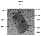
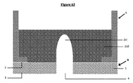
−上面、下面及び少なくとも1つの側面を含む下部ユニット(108)であって、上部オリフィス(15)及び下部オリフィス(16)を備える少なくとも1つの管状形状ダクト(14)を備える、下部ユニット(108)と、
−ベース(109)であって、
前記下部ユニット(108)が、前記ベース(109)に統合され且つ前記ベース(109)によって全体を形成し、
前記下部ユニットの前記上面が少なくとも1つのダクトの前記上部オリフィス(15)を備え、前記下部オリフィス(16)が、それ自身で又は中間手段(17)によって、前記ベース(109)の外側につながる、ベース(109)と、を備える固体の下部モジュール(107)を含むマイクロ流体細胞培養チップに関する(図41及び45)。
Lower Module According to a particular embodiment, the present invention
-A lower unit (108) comprising an upper surface, a lower surface and at least one side surface, comprising at least one tubular duct (14) having an upper orifice (15) and a lower orifice (16). When,
-Base (109)
The lower unit (108) is integrated into the base (109) and formed entirely by the base (109).
The upper surface of the lower unit comprises the upper orifice (15) of at least one duct, the lower orifice (16) being connected to the outside of the base (109) by itself or by intermediate means (17). A microfluidic cell culture chip comprising a base (109) and a solid lower module (107) (FIGS. 41 and 45).
少なくとも1つのダクトの上部オリフィスは下部ユニット内に位置し、少なくとも1つのダクトは下部ユニットを通って、その後下部モジュールのベースを通って伸び、前記ユニット及び前記ベースが1つの単一の保持の一部を形成し、少なくとも1つのダクトの下部オリフィスが前記ベースの外側につながるようになる。 The upper orifice of at least one duct is located within the lower unit, the at least one duct extends through the lower unit and then through the base of the lower module, and the unit and the base are one of a single hold. A portion is formed so that the lower orifice of at least one duct is connected to the outside of the base.
少なくとも1つのダクトの下部オリフィスは、それ自身が前記ベースの外側につながる、又は、それ自身が前記ベースの外側につながる、リザーバ等の中間手段内につながるかのいずれかである。 The lower orifice of at least one duct either connects itself to the outside of the base or into an intermediate means such as a reservoir that itself connects to the outside of the base.
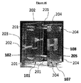
特定の実施形態によると、本発明は、前記下部モジュール(107)及び前記中央モジュール(104)は、前記下部ユニット(108)の前記上面の、少なくとも1つのダクト(14)の上部オリフィス(15)が前記中央ユニット(105)の前記支持体(1)の前記穿孔(4)の内の少なくとも1つの上で開くように組み立てられ、少なくとも1つのダクト(14)の下部オリフィス(16)が、チップの外側につながり、
前記下部ユニット(108)の前記上面及び前記中央ユニット(105)の前記支持体(3)の前記下面が互いに同一形状及び同一表面を有する、マイクロ流体細胞培養チップに関する。
According to a particular embodiment, in the present invention, the lower module (107) and the central module (104) are the upper orifice (15) of at least one duct (14) on the upper surface of the lower unit (108). Is assembled to open over at least one of the perforations (4) of the support (1) of the central unit (105), and the lower orifice (16) of the at least one duct (14) is a tip. Connected to the outside of
The present invention relates to a microfluidic cell culture chip in which the upper surface of the lower unit (108) and the lower surface of the support (3) of the central unit (105) have the same shape and the same surface as each other.
「チップの外側」との表現は、「ベースの外側」として解釈されなくてはならない。逆もまた同様である。 The expression "outside the chip" must be interpreted as "outside the base". The reverse is also true.
下部モジュールが中央モジュールへ組み立てられるとき、前記下部ユニット(108)の前記上面の、少なくとも1つのダクト(14)の上部オリフィス(15)が、前記支持体(1)の前記穿孔(4)の内の少なくとも1つの上で開いている。この少なくとも1つのダクトは、少なくとも1つの突起の内面上で、培養された細胞の分泌物を回収することを可能にさせる。 When the lower module is assembled into the central module, the upper orifice (15) of at least one duct (14) on the upper surface of the lower unit (108) is within the perforation (4) of the support (1). Open on at least one of the. This at least one duct allows the collection of cultured cell secretions on the inner surface of at least one protrusion.
この少なくとも1つのダクトはまた、培地、及び場合により、前記突起の内面上で培養される細胞を導入することを可能にさせる。 This at least one duct also allows the introduction of media and, optionally, cells to be cultured on the inner surface of the protrusion.
特定の実施形態によると、本発明は、前記下部モジュール(107)及び前記中央モジュール(104)は、前記下部ユニット(108)の前記上面の、少なくとも1つのダクト(14)の上部オリフィス(15)が前記中央ユニット(105)の前記支持体(1)の前記穿孔(4)の内の少なくとも1つの上で開くように組み立てられ、少なくとも1つのダクト(14)の下部オリフィス(16)が、液体を回収することが可能なリザーバ(17)から成る中間手段を介してチップの外側につながり、前記下部モジュール(107)のベース(109)の外側につながる出口ダクト(18)を介してチップの外側への輸送を可能にし、
前記下部ユニット(108)の前記上面及び前記中央ユニット(105)の前記支持体の前記下面が互いに同一形状及び同一表面を有する、マイクロ流体細胞培養チップに関する。
According to a particular embodiment, in the present invention, the lower module (107) and the central module (104) are the upper orifice (15) of at least one duct (14) on the upper surface of the lower unit (108). Is assembled to open over at least one of the perforations (4) of the support (1) of the central unit (105) and the lower orifice (16) of the at least one duct (14) is liquid. Outside the chip via an outlet duct (18) that connects to the outside of the chip via an intermediate means consisting of a reservoir (17) capable of recovering and connects to the outside of the base (109) of the lower module (107). Allows transportation to
The present invention relates to a microfluidic cell culture chip in which the upper surface of the lower unit (108) and the lower surface of the support of the central unit (105) have the same shape and the same surface as each other.
特定の実施形態によると、本発明は、少なくとも1つのダクト(14)の前記下部オリフィス(16)が、溶液において化合物を分析することを可能にさせるデバイス上でチップの外側につながる、マイクロ流体細胞培養チップに関する。 According to a particular embodiment, the invention is a microfluidic cell in which the lower orifice (16) of at least one duct (14) is connected to the outside of the chip on a device that allows the compound to be analyzed in solution. Regarding culture chips.
分析デバイスは、質量分析計、RMNデバイス、(液体又は気体相における)クロマトグラフデバイス、免疫学的相互作用に基づいたデバイス(ELISA、免疫沈降)、PCT又はRT−PCRデバイス等の、当業者に知られた任意の分析デバイスから成り得る。 Analytical devices include mass spectrometers, RMN devices, chromatograph devices (in liquid or gaseous phases), immunological interaction-based devices (ELISA, immunoprecipitation), PCT or RT-PCR devices, and the like. It can consist of any known analytical device.
実際、細胞の分泌物は、タンパク質及びペプチドの両方から、またDNA及びRNAから成る。そのため、選択された分析デバイスは、これらの分子の内のすべてを分析することを可能にしなくてはならない。 In fact, cellular secretions consist of both proteins and peptides, as well as DNA and RNA. Therefore, the analytical device of choice must be able to analyze all of these molecules.
特定の実施形態によると、本発明は、少なくとも1つのダクト(14)の前記下部オリフィス(16)が、溶液において化合物を分析することを可能にさせるデバイス上でチップの外側につながり、前記デバイスが質量分析計である、マイクロ流体細胞培養チップに関する。 According to a particular embodiment, the invention comprises the lower orifice (16) of at least one duct (14) to be connected to the outside of the chip on a device that allows analysis of the compound in solution. The present invention relates to a microfluidic cell culture chip, which is a mass spectrometer.
本発明によるマイクロ流体チップは、分泌物のリアルタイム且つ連続した分析を実行するために、質量分析計を統合するチップと直接結合され得る。 The microfluidic chip according to the invention can be directly coupled to a chip that integrates a mass spectrometer to perform real-time and continuous analysis of secretions.
特定の実施形態によると、本発明は、前記下部ユニット(108)及び前記中央ユニット(105)が下部モジュール(109)の及び中央モジュール(106)の、各々のベース上にそれぞれ位置する取付要素(204)によって組み立てられて、前記下部ユニット(108)の前記上面及び前記中央ユニット(105)の前記支持体(3)の前記下面を密封したやり方で組み立てる、マイクロ流体細胞培養チップに関する。 According to a particular embodiment, the invention comprises mounting elements (108) in which the lower unit (108) and the central unit (105) are respectively located on the bases of the lower module (109) and the central module (106). 204) relates to a microfluidic cell culture chip that is assembled by the lower unit (108) and the lower surface of the support (3) of the central unit (105) in a sealed manner.
特定の実施形態によると、本発明は、前記ダクト(14)の前記上部オリフィス(15)の直径d4の値が前記ダクト(14)の前記下部オリフィス(16)の直径d5の値より大きい、マイクロ流体細胞培養チップに関する。 According to a particular embodiment, the present invention is that the value of the diameter d4 of the upper orifice (15) of the duct (14) is greater than the value of the diameter d5 of the lower orifice (16) of the duct (14). Regarding fluid cell culture chips.
特定の実施形態によると、本発明は、前記ダクト(14)の前記上部オリフィス(15)の直径d4の値が前記ダクト(14)の前記下部オリフィス(16)の直径d5の値に等しく、前記少なくとも1つのダクトが円筒形状である、マイクロ流体細胞培養チップに関する。 According to a particular embodiment, in the present invention, the value of the diameter d4 of the upper orifice (15) of the duct (14) is equal to the value of the diameter d5 of the lower orifice (16) of the duct (14). It relates to a microfluidic cell culture chip in which at least one duct is cylindrical.
特定の実施形態によると、本発明は、前記少なくとも1つのダクト(14)の前記上部オリフィス(15)が直径d4、及び、前記上部オリフィス(15)の中心を通り抜け且つ前記支持体(1)に垂直な軸(t)を有し、直径d4の値が前記少なくとも1つの穿孔(4)の下部直径d2の値以上である、マイクロ流体細胞培養チップに関する。 According to a particular embodiment, the invention allows the upper orifice (15) of the at least one duct (14) to pass through a diameter d4 and the center of the upper orifice (15) and into the support (1). It relates to a microfluidic cell culture chip having a vertical axis (t) and having a value of diameter d4 greater than or equal to the value of lower diameter d2 of the at least one perforation (4).
特定の実施形態によると、本発明は、前記少なくとも1つのダクト(14)の前記上部オリフィス(15)が前記支持体(1)の1つの単一の穿孔につながる、マイクロ流体細胞培養チップに関する。 According to a particular embodiment, the invention relates to a microfluidic cell culture chip in which the upper orifice (15) of the at least one duct (14) leads to one single perforation of the support (1).
特定の実施形態によると、本発明は、前記支持体(1)の前記少なくとも1つの穿孔(4)が全体において、前記少なくとも1つのダクト(14)の前記上部オリフィス(15)に面している、マイクロ流体細胞培養チップに関する:
−前記穿孔(4)の下部直径d2の値が前記ダクト(14)の前記上部オリフィス(15)の直径d4の値と等しく、穿孔(4)の前記上部セクション(11)の中心を通り抜け且つ前記支持体(1)に垂直な軸(x)と前記ダクト(14)の前記上部オリフィス(15)の中心を通り抜け且つ前記支持体(1)に垂直な軸(t)とが組み合わされるとき(図14及び15);又は、
−前記穿孔(4)の下部直径d2の値が前記ダクト(14)の前記上部オリフィス(15)の直径d4の値未満であり、穿孔(4)の前記上部セクション(11)の中心を通り抜け且つ前記支持体(1)に垂直な軸(x)と前記ダクト(14)の前記上部オリフィス(15)の中心を通り抜け且つ前記支持体(1)に垂直な軸(t)とが組み合わされる、若しくは、[(d4の値−d2の値)/2]以下の値の距離によって互いに異なるとき(図16、17及び18)。
According to a particular embodiment, the invention faces the upper orifice (15) of the at least one duct (14) in its entirety with the at least one perforation (4) of the support (1). , Regarding microfluidic cell culture chips:
-The value of the lower diameter d2 of the perforation (4) is equal to the value of the diameter d4 of the upper orifice (15) of the duct (14), passes through the center of the upper section (11) of the perforation (4) and said. When the axis (x) perpendicular to the support (1) and the axis (t) passing through the center of the upper orifice (15) of the duct (14) and perpendicular to the support (1) are combined (FIG. 14 and 15); or
-The value of the lower diameter d2 of the perforation (4) is less than the value of the diameter d4 of the upper orifice (15) of the duct (14) and passes through the center of the upper section (11) of the perforation (4). An axis (x) perpendicular to the support (1) and an axis (t) passing through the center of the upper orifice (15) of the duct (14) and perpendicular to the support (1) are combined or combined. , [(Value of d4 − value of d2) / 2] When the values differ from each other depending on the distance of the following values (FIGS. 16, 17 and 18).
特定の実施形態によると、本発明は、前記支持体(1)の前記少なくとも1つの穿孔(4)が、前記少なくとも1つのダクト(14)の前記上部オリフィス(15)に部分的に面している、マイクロ流体細胞培養チップに関する:
−前記穿孔(4)の下部直径d2の値が前記ダクト(14)の前記上部オリフィス(15)の直径d4の値に等しく、穿孔(4)の前記上部セクション(11)の中心を通り抜け且つ前記支持体(1)に垂直な軸(x)と前記ダクト(14)の前記上部オリフィス(15)の中心を通り抜け且つ前記支持体(1)に垂直な軸(t)とが、[d4の値/2]以下の値の距離によって互いに異なるとき(図19、21、22、24、29及び30)、又は、
−前記穿孔(4)の下部直径d2の値が前記ダクト(14)の前記上部オリフィス(15)の直径d4の値未満であり、穿孔(4)の前記上部セクション(11)の中心を通り抜け且つ前記支持体(1)に垂直な軸(x)と前記ダクト(14)の前記上部オリフィス(15)の中心を通り抜け且つ前記支持体(1)に垂直な軸(t)とが、[d4の値/2]以下の値の距離によって互いに異なるとき(図20、23、25、26、27及び28)。
According to a particular embodiment, the present invention allows the at least one perforation (4) of the support (1) to partially face the upper orifice (15) of the at least one duct (14). Regarding microfluidic cell culture chips:
-The value of the lower diameter d2 of the perforation (4) is equal to the value of the diameter d4 of the upper orifice (15) of the duct (14), passes through the center of the upper section (11) of the perforation (4) and said. The axis (x) perpendicular to the support (1) and the axis (t) passing through the center of the upper orifice (15) of the duct (14) and perpendicular to the support (1) are [values of d4]. / 2] When they differ from each other depending on the distance of the following values (FIGS. 19, 21, 22, 24, 29 and 30), or
-The value of the lower diameter d2 of the perforation (4) is less than the value of the diameter d4 of the upper orifice (15) of the duct (14) and passes through the center of the upper section (11) of the perforation (4). The axis (x) perpendicular to the support (1) and the axis (t) passing through the center of the upper orifice (15) of the duct (14) and perpendicular to the support (1) are [d4. Value / 2] When the values are different from each other depending on the distance of the following values (FIGS. 20, 23, 25, 26, 27 and 28).
特定の実施形態によると、本発明は、前記下部モジュール(107)が少なくとも2つのダクト(14)を備えるマイクロ流体細胞培養チップに関する。 According to a particular embodiment, the invention relates to a microfluidic cell culture chip in which the lower module (107) comprises at least two ducts (14).
特定の実施形態によると、本発明は、少なくとも2つのダクト(14)の、各々の上部オリフィス(15)が穿孔(4)につながり、少なくとも2つのダクト(14)の少なくとも2つの下部オリフィス(16)が少なくとも2つの異なるサイトへそれぞれ、チップの外側につながる、マイクロ流体細胞培養チップに関する(図32)。 According to a particular embodiment, the present invention relates to at least two ducts (14), each upper orifice (15) leading to a perforation (4) and at least two lower orifices (16) in at least two ducts (14). ) Relate to at least two different sites, respectively, to the outside of the chip, relating to a microfluidic cell culture chip (FIG. 32).
特定の実施形態によると、本発明は、少なくとも2つのダクト(14)の、各々の上部オリフィス(15)が穿孔(4)につながり、少なくとも2つのダクト(14)の少なくとも2つの下部オリフィス(16)が、液体を回収することが可能なリザーバ(17)から成る中間手段にそれぞれつながり、前記下部モジュール(107)のベース(109)の外側につながる出口ダクト(18)を介してチップの外側への輸送を可能にさせる、マイクロ流体細胞培養チップに関する(図31)。 According to a particular embodiment, the present invention relates to at least two ducts (14), each upper orifice (15) leading to a perforation (4) and at least two lower orifices (16) in at least two ducts (14). ) Connect to an intermediate means consisting of a reservoir (17) capable of recovering the liquid, and to the outside of the chip via an outlet duct (18) connected to the outside of the base (109) of the lower module (107). With respect to a microfluidic cell culture chip that allows for transport of (FIG. 31).
特定の実施形態によると、本発明は、少なくとも2つのダクト(14)の、各々の上部オリフィス(15)が穿孔(4)につながり、少なくとも2つのダクト(14)の少なくとも2つの下部オリフィス(16)が、液体を回収することが可能なリザーバ(17)から成る中間手段にそれぞれつながり、前記下部モジュール(107)のベース(109)の外側につながる出口ダクト(18)を介してチップの外側への輸送を可能にさせ、各々の前記リザーバの前記出口ダクトが互いに接続されて同じサイトでチップの外側につながる、マイクロ流体細胞培養チップに関する(図34)。 According to a particular embodiment, the present invention relates to at least two ducts (14), each upper orifice (15) leading to a perforation (4) and at least two lower orifices (16) in at least two ducts (14). ) Connect to an intermediate means consisting of a reservoir (17) capable of recovering the liquid, and to the outside of the chip via an outlet duct (18) connected to the outside of the base (109) of the lower module (107). With respect to a microfluidic cell culture chip, the outlet ducts of each of the reservoirs are connected to each other and connected to the outside of the chip at the same site, allowing for transport of the reservoir (FIG. 34).
特定の実施形態によると、本発明は、少なくとも2つのダクト(14)が互いに接続されてネットワークを形成して、少なくとも2つのダクト(14)の、各々の上部オリフィス(15)が穿孔(4)につながり、各々の少なくとも2つのダクト(14)の下部オリフィス(16)がそれら自身で、同じサイトでチップの外側に、又は、液体を回収することが可能なリザーバ(17)から成る中間手段を介して、つながり、前記下部モジュール(107)のベース(109)の外側につながる出口ダクト(18)を介してチップの外側への輸送を可能にさせる、マイクロ流体細胞培養チップに関する(図33及び35)。 According to a particular embodiment, the invention comprises connecting at least two ducts (14) to each other to form a network in which the upper orifices (15) of at least two ducts (14) are perforated (4). An intermediate means consisting of a reservoir (17) in which the lower orifice (16) of each at least two ducts (14) is capable of recovering the liquid on its own, outside the chip at the same site, or to. With respect to microfluidic cell culture chips (FIGS. 33 and 35), which are connected through and allow transport to the outside of the chip via an outlet duct (18) that connects to the outside of the base (109) of the lower module (107). ).
特定の実施形態によると、本発明は、少なくとも2つのダクト(14)の、各々の上部オリフィス(15)が穿孔(4)につながり、少なくとも2つのダクト(14)の第1のセットの少なくとも2つの下部オリフィス(16)が、リザーバ(17)から成る第1の中間手段につながり、
少なくとも2つのダクト(14)の、1つの第2のセットの少なくとも2つの下部オリフィス(16)が、リザーバ(17)から成る少なくとも1つの第2の中間手段につながり、
前記第1の及び少なくとも第2のリザーバ(17)が液体を回収することが可能であり、且つ、異なるサイトで、前記下部モジュール(107)のベース(109)の外側につながる個別の出口ダクト(18)を介してチップの外側への輸送を各々可能にさせる、マイクロ流体細胞培養チップに関する(図37)。
According to a particular embodiment, the present invention relates to at least two ducts (14), each of which has an upper orifice (15) connected to a perforation (4) and at least two of the first set of at least two ducts (14). One lower orifice (16) leads to a first intermediate means consisting of a reservoir (17),
At least two lower orifices (16) in one second set of at least two ducts (14) connect to at least one second intermediate means consisting of a reservoir (17).
Separate outlet ducts (17) into which the first and at least second reservoirs (17) are capable of recovering fluid and at different sites are connected to the outside of the base (109) of the lower module (107). 18) relates to a microfluidic cell culture chip, each of which allows transport to the outside of the chip via 18) (FIG. 37).
特定の実施形態によると、本発明は、少なくとも2つのダクト(14)の各々の上部オリフィス(15)が穿孔(4)につながり、少なくとも2つのダクト(14)のセットの少なくとも2つの下部オリフィス(16)が、液体を回収することが可能なリザーバ(17)から成る1つの同じ中間手段につながり、且つ前記下部モジュール(107)のベース(109)の外側につながる出口ダクト(18)を介してチップの外側への輸送を可能にさせる、マイクロ流体細胞培養チップに関する(図36)。 According to a particular embodiment, the invention comprises at least two lower orifices (14) in a set of at least two ducts (14), with each upper orifice (15) of at least two ducts (14) connected to a perforation (4). 16) is connected to one same intermediate means consisting of a reservoir (17) capable of recovering the liquid, and via an outlet duct (18) connected to the outside of the base (109) of the lower module (107). It relates to a microfluidic cell culture chip that allows transport to the outside of the chip (FIG. 36).
特定の実施形態によると、本発明は、前記下部モジュール(107)が100μmから2cmの高さを有するマイクロ流体細胞培養チップに関する。 According to a particular embodiment, the present invention relates to a microfluidic cell culture chip in which the lower module (107) has a height of 100 μm to 2 cm.
特定の実施形態によると、本発明は、下部モジュール(107)の前記ベース(109)が100μmから2cmの高さを有するマイクロ流体細胞培養チップに関する。 According to a particular embodiment, the present invention relates to a microfluidic cell culture chip in which the base (109) of the lower module (107) has a height of 100 μm to 2 cm.
特定の実施形態によると、本発明は、前記下部ユニット(108)が100μmから2cmの高さを有するマイクロ流体細胞培養チップに関する。 According to a particular embodiment, the present invention relates to a microfluidic cell culture chip in which the lower unit (108) has a height of 100 μm to 2 cm.
特定の実施形態によると、本発明は、下部モジュール(107)がバイオプリントプラスチック、ポリカーボネート、組織培養プラスチック、又はSU8から成るマイクロ流体細胞培養チップに関する。 According to a particular embodiment, the present invention relates to a microfluidic cell culture chip in which the lower module (107) consists of bioprinted plastic, polycarbonate, tissue culture plastic, or SU8.
特定の実施形態によると、本発明は、下部モジュール(107)がバイオプリントプラスチック、ポリカーボネート、組織培養プラスチック、ガラス又はSU−8樹脂から成り、前記下部モジュール(107)が透明である、マイクロ流体細胞培養チップに関する。 According to a particular embodiment, the present invention is a microfluidic cell in which the lower module (107) is made of bioprinted plastic, polycarbonate, tissue culture plastic, glass or SU-8 resin and the lower module (107) is transparent. Regarding culture chips.
特定の実施形態によると、本発明は、下部モジュール(109)のベースがバイオプリントプラスチック、ポリカーボネート、組織培養プラスチック、又はSU8から成るマイクロ流体細胞培養チップに関する。 According to a particular embodiment, the invention relates to a microfluidic cell culture chip in which the base of the lower module (109) consists of bioprinted plastic, polycarbonate, tissue culture plastic, or SU8.
特定の実施形態によると、本発明は、下部モジュール(109)のベースがバイオプリントプラスチック、ポリカーボネート、組織培養プラスチック、ガラス又はSU−8樹脂から成り、下部モジュール(109)の前記ベースが透明である、マイクロ流体細胞培養チップに関する。 According to certain embodiments, the invention comprises a lower module (109) base made of bioprinted plastic, polycarbonate, tissue culture plastic, glass or SU-8 resin, the base of which the lower module (109) is transparent. , Concerning microfluidic cell culture chips.
特定の実施形態によると、本発明は、下部ユニット(108)がバイオプリントプラスチック、ポリカーボネート、組織培養プラスチック、又はSU8から成るマイクロ流体細胞培養チップに関する。 According to a particular embodiment, the present invention relates to a microfluidic cell culture chip in which the lower unit (108) consists of bioprinted plastic, polycarbonate, tissue culture plastic, or SU8.
特定の実施形態によると、本発明は、下部ユニット(108)がバイオプリントプラスチック、ポリカーボネート、組織培養プラスチック、ガラス又はSU−8樹脂から成り、前記下部ユニット(108)が透明である、マイクロ流体細胞培養チップに関する。 According to certain embodiments, the present invention is a microfluidic cell in which the lower unit (108) is made of bioprinted plastic, polycarbonate, tissue culture plastic, glass or SU-8 resin and the lower unit (108) is transparent. Regarding culture chips.
上部モジュール
特定の実施形態によると、本発明は、以下を備える上部モジュール(101)を含むマイクロ流体細胞培養チップ関する:
−開放容積(チャンバ)(203)を画定する固体の表面、及び、前記中央モジュール(104)の前記中央ユニット(105)と接触して前記開放容積の開口部の表面を区切ることが可能な固体の表面の端から成る、固体の且つ中空の上部ユニット(102)と;
−ベース(103)であって、
前記上部ユニット(102)が、前記ベース(103)に統合され且つ前記ベース(103)によって全体を形成する、ベース(103)と、を備える上部モジュール(101)を含む、ベース(103)と。
Upper Module According to a particular embodiment, the present invention relates to a microfluidic cell culture chip comprising an upper module (101) comprising:
-A solid surface that defines an open volume (chamber) (203) and a solid that can contact the central unit (105) of the central module (104) to separate the surface of the opening of the open volume. With a solid and hollow upper unit (102) consisting of the edges of the surface of the
-Base (103)
A base (103) comprising an upper module (101) comprising a base (103) in which the upper unit (102) is integrated into the base (103) and formed entirely by the base (103).
チャンバ(203)は、上部モジュール(101)のベース(103)において統合され、且つ、前記チャンバ(203)の開放容積の表面を除いて、前記ベース(103)によってその表面のすべての上でこのように囲まれて位置する。 The chamber (203) is integrated in the base (103) of the upper module (101) and is this over all of its surface by the base (103) except the surface of the open volume of the chamber (203). It is located surrounded by.
特定の実施形態によると、本発明は、前記上部モジュール(101)の前記上部ユニット(102)及び前記中央モジュール(104)の前記中央ユニット(105)は、前記上部ユニット(102)の開口部の前記表面が前記中央ユニット(105)の3Dナノ構造多孔質膜(5)の前記上面(6)の上に位置付けられるように組み立てられ、開口部の前記表面及び前記上面(6)が互いに同一形状及び同一表面を有する、マイクロ流体細胞培養チップに関する。 According to a particular embodiment, in the present invention, the upper unit (102) of the upper module (101) and the central unit (105) of the central module (104) are the openings of the upper unit (102). The surface is assembled so that it is positioned on the top surface (6) of the 3D nanostructured porous membrane (5) of the central unit (105), and the surface and top surface (6) of the opening have the same shape. And with respect to microfluidic cell culture chips having the same surface.
特定の実施形態では、上部ユニットは、3Dナノ構造多孔質膜の外面及び少なくとも1つの突起の外面上で細胞培養を観察するために、顕微鏡観察に適合した、透明ガラス部品、好ましくは顕微鏡スライドを挿入することを可能にする前記チャンバから成る固体の表面で、外側上の開口部(窓)を備える。 In certain embodiments, the upper unit has a clear glass component, preferably a microscope slide, suitable for microscopic observation to observe cell cultures on the outer surface of a 3D nanostructured porous membrane and on the outer surface of at least one protrusion. A solid surface consisting of the chamber that allows insertion, with an opening (window) on the outside.
開口部は好ましくは、前記チャンバの固体の表面の場所に、位置して、それが突起の外面上で細胞培養の観察を垂直に可能にさせるようにする。 The opening is preferably located at the location of the solid surface of the chamber, allowing for vertical observation of the cell culture on the outer surface of the protrusion.
前記透明ガラス部分は、前記チャンバから成る固体の表面の前記開口部上に位置付けられ、前記上部ユニットへ封止されて維持されて、上部ユニットと中央ユニットとの間で閉鎖空間を維持する。 The clear glass portion is located on the opening on the surface of the solid consisting of the chamber and is sealed and maintained in the upper unit to maintain a closed space between the upper unit and the central unit.
好ましくは、前記透明ガラス部分は、封止接着剤を用いて前記上部ユニットへ封止されて維持される。 Preferably, the transparent glass portion is sealed and maintained in the upper unit using a sealing adhesive.
特定の実施形態によると、本発明は、前記上部モジュール(101)の前記上部ユニット(102)及び前記中央モジュール(104)の前記中央ユニット(105)が、上部モジュール(101)の及び中央モジュール(104)の、各々のベース(103、106)上に位置する取付要素(201、204)によって組み立てられて、前記上部ユニット(102)の開口部の前記表面及び前記中央ユニット(105)の3Dナノ構造多孔質膜(5)の前記上面(6)を、密封したやり方で、組み立てる、マイクロ流体細胞培養チップに関する。 According to a particular embodiment, the invention comprises the upper unit (102) of the upper module (101) and the central unit (105) of the central module (104) being the upper module (101) and the central module (101). 104), assembled by mounting elements (201, 204) located on each base (103, 106), the surface of the opening of the upper unit (102) and the 3D nano of the central unit (105). The present invention relates to a microfluidic cell culture chip in which the upper surface (6) of the structural porous membrane (5) is assembled in a sealed manner.
特定の実施形態によると、本発明は、前記固体の矩形面に隣接し且つ互いに隣接した、4つの固体面及び固体の矩形面を固体の表面が備える、前記固体の且つ中空上部ユニット(102)が前記チャンバ(203)を形成し、前記4つの固体面の自由端が前記チャンバ(206)の開口部の前記表面を区切る、マイクロ流体細胞培養チップに関する。 According to a particular embodiment, the present invention is the solid and hollow upper unit (102), wherein the solid surface comprises four solid surfaces adjacent to and adjacent to each other the rectangular surface of the solid. The present invention relates to a microfluidic cell culture chip, wherein the chamber (203) is formed and the free ends of the four solid surfaces separate the surface of the opening of the chamber (206).
特定の実施形態によると、本発明は、上部モジュール(101)がバイオプリントプラスチック、ポリカーボネート、組織培養プラスチック、又はSU8から成るマイクロ流体細胞培養チップに関する。 According to a particular embodiment, the present invention relates to a microfluidic cell culture chip in which the upper module (101) consists of bioprinted plastic, polycarbonate, tissue culture plastic, or SU8.
特定の実施形態によると、本発明は、上部モジュール(101)がバイオプリントプラスチック、ポリカーボネート、組織培養プラスチック、ガラス又はSU−8樹脂から成り、前記上部モジュール(101)が透明である、マイクロ流体細胞培養チップに関する。 According to certain embodiments, the present invention is a microfluidic cell in which the upper module (101) is made of bioprinted plastic, polycarbonate, tissue culture plastic, glass or SU-8 resin and the upper module (101) is transparent. Regarding culture chips.
特定の実施形態によると、本発明は、上部モジュール(103)のベースがバイオプリントプラスチック、ポリカーボネート、組織培養プラスチック、又はSU8から成るマイクロ流体細胞培養チップに関する。 According to a particular embodiment, the invention relates to a microfluidic cell culture chip in which the base of the upper module (103) consists of bioprinted plastic, polycarbonate, tissue culture plastic, or SU8.
特定の実施形態によると、本発明は、上部モジュール(103)のベースがバイオプリントプラスチック、ポリカーボネート、組織培養プラスチック、ガラス又はSU−8樹脂から成り、上部モジュール(103)の前記ベースが透明である、マイクロ流体細胞培養チップに関する。 According to a particular embodiment, the invention consists of a base of the upper module (103) made of bioprinted plastic, polycarbonate, tissue culture plastic, glass or SU-8 resin, the base of the upper module (103) being transparent. , Concerning microfluidic cell culture chips.
特定の実施形態によると、本発明は、上部ユニット(102)がバイオプリントプラスチック、ポリカーボネート、組織培養プラスチック、又はSU8から成るマイクロ流体細胞培養チップに関する。 According to a particular embodiment, the present invention relates to a microfluidic cell culture chip in which the upper unit (102) consists of bioprinted plastic, polycarbonate, tissue culture plastic, or SU8.
特定の実施形態によると、本発明は、上部ユニット(102)がバイオプリントプラスチック、ポリカーボネート、組織培養プラスチック、ガラス又はSU−8樹脂から成り、前記上部ユニット(102)が透明である、マイクロ流体細胞培養チップに関する。 According to certain embodiments, the present invention is a microfluidic cell in which the upper unit (102) is made of bioprinted plastic, polycarbonate, tissue culture plastic, glass or SU-8 resin and the upper unit (102) is transparent. Regarding culture chips.
特定の実施形態によると、本発明は、前記上部ユニット(102)の前記チャンバ(203)の開口部の前記表面が前記中央ユニット(105)の3Dナノ構造多孔質膜(5)の前記上面(6)の上に位置付けられて、前記上部ユニット(102)の前記固体の表面及び3Dナノ構造多孔質膜(5)の前記上面(6)によって区切られた閉鎖空間を形成する、マイクロ流体細胞培養チップに関する。 According to a particular embodiment, the present invention has the surface of the opening of the chamber (203) of the upper unit (102) the upper surface of the 3D nanostructured porous membrane (5) of the central unit (105). Microfluidic cell culture positioned on top of 6) to form a closed space separated by the solid surface of the upper unit (102) and the upper surface (6) of the 3D nanostructured porous membrane (5). Regarding chips.
特定の実施形態によると、本発明は、前記上部ユニット(102)の前記チャンバ(203)の開口部の前記表面が前記中央ユニット(105)の3Dナノ構造多孔質膜(5)の前記上面(6)の上に位置付けられ、前記上部ユニット(102)の前記少なくとも1つの固体面が入口/出口ダクト(202)にそれぞれつながる2つのオリフィスを有して、
ベース(109)の外側につながる前記入口/出口ダクト(202)を介して前記2つのオリフィスによってのみ、前記マイクロ流体チップの外側と連通し得る前記中央ユニット(105)の3Dナノ構造多孔質膜(5)の前記上面(6)と前記上部ユニット(102)の前記固体の表面とによって区切られた閉鎖空間を形成する、マイクロ流体細胞培養チップに関する(図38及び43)。
According to a particular embodiment, the present invention has the surface of the opening of the chamber (203) of the upper unit (102) the upper surface of the 3D nanostructured porous membrane (5) of the central unit (105). Positioned on top of 6), said at least one solid surface of the upper unit (102) has two orifices each connected to an inlet / outlet duct (202).
A 3D nanostructured porous membrane of the central unit (105) that can communicate with the outside of the microfluidic chip only by the two orifices through the inlet / outlet duct (202) leading to the outside of the base (109). 5) relates to a microfluidic cell culture chip that forms a closed space separated by the upper surface (6) of 5) and the solid surface of the upper unit (102) (FIGS. 38 and 43).
上部ユニットが、入口/出口ダクトにそれぞれつながる2つのオリフィスを備える。2つの入口/出口ダクトは上部モジュールのベースを通って伸び、前記ユニット及び前記ベースは1つの単一の保持の一部を形成し、前記2つの入口/出口ダクトは前記上部ベースの外側につながるようになる。 The upper unit comprises two orifices, each connected to an inlet / outlet duct. The two inlet / outlet ducts extend through the base of the upper module, the unit and the base form part of one single hold, and the two inlet / exit ducts connect to the outside of the upper base. Will be.
上部モジュールが中央モジュールへ組み立てられるとき、3Dナノ構造多孔質膜上のチャンバのアセンブリは、前記入口/出口ダクトを介して前記2つのオリフィスによってのみ、前記マイクロ流体チップの外側と連通し得る閉鎖空間を画定することを可能にさせる。これらのダクトはまた、チャンバにおける培地の導入を、及び場合により、前記膜の上面又は少なくとも1つの突起の外面上で培養される細胞の導入を可能にさせる。 When the upper module is assembled into the central module, the assembly of the chamber on the 3D nanostructured porous membrane is a closed space that can communicate with the outside of the microfluidic chip only by the two orifices through the inlet / outlet ducts. Allows you to define. These ducts also allow the introduction of medium in the chamber and, optionally, the cells cultured on the upper surface of the membrane or the outer surface of at least one protrusion.
これらの入口/出口ダクトはセンサーと結合され得て、培養条件及びパラメータ(CO2、O2、圧力、温度、グルコース、pHセンサー)の連続したモニタリングを可能にさせる。代替実施形態では、これらのセンサーは、チャンバ(203)において直接統合され得る。 These inlet / outlet ducts can be coupled with sensors to allow continuous monitoring of culture conditions and parameters (CO 2 , O 2 , pressure, temperature, glucose, pH sensors). In an alternative embodiment, these sensors may be integrated directly in the chamber (203).
特定の実施形態によると、本発明は、前記上部モジュール(101)が50μmから2cmの、特に1cmの高さを有するマイクロ流体細胞培養チップに関する。 According to a particular embodiment, the present invention relates to a microfluidic cell culture chip in which the upper module (101) has a height of 50 μm to 2 cm, particularly 1 cm.
特定の実施形態によると、本発明は、前記上部モジュール(101)の前記ベース(103)が50μmから2cmの、特に1cmの高さを有するマイクロ流体細胞培養チップに関する。 According to a particular embodiment, the present invention relates to a microfluidic cell culture chip in which the base (103) of the upper module (101) has a height of 50 μm to 2 cm, particularly 1 cm.
特定の実施形態によると、本発明は、前記上部モジュール(101)の前記上部ユニット(102)が50μmから2cmの、特に1cmの高さを有するマイクロ流体細胞培養チップに関する。 According to a particular embodiment, the present invention relates to a microfluidic cell culture chip in which the upper unit (102) of the upper module (101) has a height of 50 μm to 2 cm, particularly 1 cm.
3つのモジュールのアセンブリ
特定の実施形態によると、本発明は、上部モジュール(101)、中央モジュール(104)及び下部モジュール(107)を備え、上記前記モジュールは、
前記上部モジュール(101)の前記上部ユニット(102)の開口部の前記表面が、前記中央モジュール(104)の前記中央ユニット(105)の3Dナノ構造多孔質膜(5)の前記上面(2)の上に位置付けられ、
前記下部モジュール(107)の前記下部ユニット(108)の前記上面の、少なくとも1つのダクト(14)の上部オリフィス(15)が、前記中央ユニット(105)の前記支持体(1)の前記穿孔(4)の内の少なくとも1つの上で開いており、
前記上部ユニット(102)の開口部の前記表面及び前記中央ユニット(105)の3Dナノ構造多孔質膜(5)の前記上面(2)が、互いに同一形状及び同一表面を有し、
前記下部ユニット(108)の前記上面及び前記中央ユニット(105)の前記支持体(3)の前記下面が互いに同一形状及び同一表面を有し、
前記上部モジュール(101)、前記中央モジュール(104)及び前記下部モジュール(107)が、各々の個別のベース(103、106、109)上に位置する取付要素(201、204)によって組み立てられる、ように組み立てられる、マイクロ流体細胞培養チップに関する(図42、46及び47)。
Assembly of Three Modules According to a particular embodiment, the present invention comprises an upper module (101), a central module (104) and a lower module (107), wherein said module.
The surface of the opening of the upper unit (102) of the upper module (101) is the upper surface (2) of the 3D nanostructured porous membrane (5) of the central unit (105) of the central module (104). Positioned on top of
The upper orifice (15) of at least one duct (14) on the upper surface of the lower unit (108) of the lower module (107) is the perforation (1) of the support (1) of the central unit (105). Open on at least one of 4)
The surface of the opening of the upper unit (102) and the upper surface (2) of the 3D nanostructured porous membrane (5) of the central unit (105) have the same shape and surface as each other.
The upper surface of the lower unit (108) and the lower surface of the support (3) of the central unit (105) have the same shape and the same surface as each other.
The upper module (101), the central module (104) and the lower module (107) are assembled by mounting elements (201, 204) located on their respective individual bases (103, 106, 109). With respect to microfluidic cell culture chips assembled in (FIGS. 42, 46 and 47).
各々のモジュールのベース上に位置する取付要素は、モジュール2つずつロックして、中央モジュールによって上部モジュールを組み立て且つ下部モジュールによって中央モジュールを組み立てる、又は、第3のモジュール上に2つのモジュールをロックして、上部モジュール上で下部モジュール及び中央モジュールを組み立てる、のいずれかを可能にさせる。 Mounting elements located on the base of each module lock two modules at a time, assembling the upper module with the central module and assembling the central module with the lower module, or locking two modules on the third module. It allows either the lower module or the central module to be assembled on the upper module.
これらの取付要素は、オス/メス取手又は要素、好ましくはオス/メス要素であり得る。 These mounting elements can be male / female handles or elements, preferably male / female elements.
特定の実施形態によると、上部モジュールのベースは、オス取付要素として高台(201)を備え、中央モジュール及び下部モジュールのベースは、メス取付要素として穿孔(204)を備えて、上部モジュールの前記高台上にロックされることを可能にする。 According to certain embodiments, the base of the upper module is provided with a pedestal (201) as a male mounting element and the bases of the central and lower modules are provided with a perforation (204) as a female mounting element to provide the pedestal of the upper module. Allows it to be locked up.
特定の実施形態によると、本発明は、前記突起(8)の前記内面(10)が全体において、前記ダクト(14)の前記上部オリフィス(15)に面しているマイクロ流体細胞培養チップに関する:
前記少なくとも1つの突起(8)の前記内面(10)が全体において、前記支持体(1)の前記少なくとも1つの穿孔(4)に面しているとき:
−前記少なくとも1つの穿孔(4)の上部直径d1の値が前記少なくとも1つの突起(4)の直径d3の値以上であり、前記円形ベース(13)の中心を通り抜け且つ前記支持体(1)に垂直な軸(y)と前記穿孔(4)の上部セクション(11)の中心を通り抜け且つ前記支持体(1)に垂直な軸(x)とが組み合わされるようなとき;又は、
−前記少なくとも1つの穿孔(4)の上部直径d1の値が前記少なくとも1つの突起(8)の直径d3の値より大きく、前記円形ベース(13)の中心を通り抜け且つ前記支持体(1)に垂直な軸(y)と前記穿孔(4)の上部セクション(11)の中心を通り抜け且つ前記支持体(1)に垂直な軸(x)とが[(d1の値−d3の値)/2]以下の値の距離によって互いに異なるように;
及び、前記支持体(1)の前記穿孔(4)が全体において、前記ダクト(14)の前記上部オリフィス(15)に面しているとき:
前記突起(8)の前記円形ベース(13)の中心を通り抜け且つ前記支持体(1)に垂直な軸(y)と前記ダクト(14)の前記上部オリフィス(15)の中心を通り抜け且つ前記支持体(1)に垂直な軸(t)とが、組み合わされる、又は、d4の値がd2の値より大きいとき[(d4の値−d3の値)/2]以下の距離によって互いに異なるように。
According to a particular embodiment, the present invention relates to a microfluidic cell culture chip in which the inner surface (10) of the projection (8) faces the upper orifice (15) of the duct (14) as a whole:
When the inner surface (10) of the at least one protrusion (8) faces the at least one perforation (4) of the support (1) as a whole:
-The value of the upper diameter d1 of the at least one perforation (4) is greater than or equal to the value of the diameter d3 of the at least one protrusion (4), passing through the center of the circular base (13) and the support (1). When the axis (y) perpendicular to the axis (y) and the axis (x) passing through the center of the upper section (11) of the perforation (4) and perpendicular to the support (1) are combined; or
-The value of the upper diameter d1 of the at least one perforation (4) is greater than the value of the diameter d3 of the at least one protrusion (8), passing through the center of the circular base (13) and into the support (1). The vertical axis (y) and the axis (x) passing through the center of the upper section (11) of the perforation (4) and perpendicular to the support (1) are [(value of d1 − value of d3) / 2). ] To be different from each other depending on the distance of the following values;
And when the perforation (4) of the support (1) faces the upper orifice (15) of the duct (14) as a whole:
Through the center of the circular base (13) of the protrusion (8) and through the center of the axis (y) perpendicular to the support (1) and the upper orifice (15) of the duct (14) and the support. When the axis (t) perpendicular to the body (1) is combined or the value of d4 is larger than the value of d2 [(value of d4 − value of d3) / 2] or less, they differ from each other depending on the distance. ..
特定の実施形態によると、本発明は、前記突起(8)の前記内面(10)が部分的に、前記ダクト(14)の前記上部オリフィス(15)に面している、マイクロ流体細胞培養チップに関する:
前記少なくとも1つの突起(8)の前記内面(10)が全体において、前記支持体(1)の前記少なくとも1つの穿孔(4)に面しているとき:
−前記少なくとも1つの穿孔(4)の上部直径d1の値が前記少なくとも1つの突起(4)の直径d3の値以上であり、前記円形ベース(13)の中心を通り抜け且つ前記支持体(1)に垂直な軸(y)と前記穿孔(4)の上部セクション(11)の中心を通り抜け且つ前記支持体(1)に垂直な軸(x)とが組み合わされるようなとき;又は、
−前記少なくとも1つの穿孔(4)の上部直径d1の値が前記少なくとも1つの突起(8)の直径d3の値より大きく、前記円形ベース(13)の中心を通り抜け且つ前記支持体(1)に垂直な軸(y)と前記穿孔(4)の上部セクション(11)の中心を通り抜け且つ前記支持体(1)に垂直な軸(x)とが[(d1の値−d3の値)/2]以下の値の距離によって互いに異なるように。
及び
−前記突起(8)の前記円形ベース(13)の中心を通り抜け且つ前記支持体(1)に垂直な軸(y)と前記ダクト(14)の前記上部オリフィス(15)の中心を通り抜け且つ前記支持体(1)に垂直な軸(t)とが、組み合わされる、若しくは、[(d4の値/2)+(d3の値の4/10)]以下距離によって互いに異なる。
According to a particular embodiment, the present invention is a microfluidic cell culture chip in which the inner surface (10) of the projection (8) partially faces the upper orifice (15) of the duct (14). Regarding:
When the inner surface (10) of the at least one protrusion (8) faces the at least one perforation (4) of the support (1) as a whole:
-The value of the upper diameter d1 of the at least one perforation (4) is greater than or equal to the value of the diameter d3 of the at least one protrusion (4), passing through the center of the circular base (13) and the support (1). When the axis (y) perpendicular to the axis (y) and the axis (x) passing through the center of the upper section (11) of the perforation (4) and perpendicular to the support (1) are combined; or
-The value of the upper diameter d1 of the at least one perforation (4) is greater than the value of the diameter d3 of the at least one protrusion (8), passing through the center of the circular base (13) and into the support (1). The vertical axis (y) and the axis (x) passing through the center of the upper section (11) of the perforation (4) and perpendicular to the support (1) are [(value of d1 − value of d3) / 2). ] Different from each other depending on the distance of the following values.
And-passing through the center of the circular base (13) of the protrusion (8) and through the center of the axis (y) perpendicular to the support (1) and the upper orifice (15) of the duct (14). The axis (t) perpendicular to the support (1) is combined or differs from each other depending on the distance of [(d4 value / 2) + (
特定の実施形態によると、本発明は、前記突起(8)の前記内面(10)が部分的に、前記ダクト(14)の前記上部オリフィス(15)に面している、マイクロ流体細胞培養チップに関する:
前記少なくとも1つの突起(8)の前記内面(10)が全体において、前記支持体(1)の前記少なくとも1つの穿孔(4)に面しているとき:
−前記少なくとも1つの穿孔(4)の上部直径d1の値が前記少なくとも1つの突起(4)の直径d3の値以上であり、前記円形ベース(13)の中心を通り抜け且つ前記支持体(1)に垂直な軸(y)と前記穿孔(4)の上部セクション(11)の中心を通り抜け且つ前記支持体(1)に垂直な軸(x)とが組み合わされるようなとき;又は、
−前記少なくとも1つの穿孔(4)の上部直径d1の値が前記少なくとも1つの突起(8)の直径d3の値より大きく、前記円形ベース(13)の中心を通り抜け且つ前記支持体(1)に垂直な軸(y)と前記穿孔(4)の上部セクション(11)の中心を通り抜け且つ前記支持体(1)に垂直な軸(x)とが[(d1の値−d3の値)/2]以下の値の距離によって互いに異なるように。
及び
−前記突起(8)の前記円形ベース(13)の中心を通り抜け且つ前記支持体(1)に垂直な軸(y)と前記ダクト(14)の前記上部オリフィス(15)の中心を通り抜け且つ前記支持体(1)に垂直な軸(t)とが、組み合わされる、又は、[[(d4の値+d4の値)/2]−10μm]以下距離によって互いに異なるとき。
According to a particular embodiment, the present invention is a microfluidic cell culture chip in which the inner surface (10) of the projection (8) partially faces the upper orifice (15) of the duct (14). Regarding:
When the inner surface (10) of the at least one protrusion (8) faces the at least one perforation (4) of the support (1) as a whole:
-The value of the upper diameter d1 of the at least one perforation (4) is greater than or equal to the value of the diameter d3 of the at least one protrusion (4), passing through the center of the circular base (13) and the support (1). When the axis (y) perpendicular to the axis (y) and the axis (x) passing through the center of the upper section (11) of the perforation (4) and perpendicular to the support (1) are combined; or
-The value of the upper diameter d1 of the at least one perforation (4) is greater than the value of the diameter d3 of the at least one protrusion (8), passing through the center of the circular base (13) and into the support (1). The vertical axis (y) and the axis (x) passing through the center of the upper section (11) of the perforation (4) and perpendicular to the support (1) are [(value of d1 − value of d3) / 2). ] Different from each other depending on the distance of the following values.
And-through the center of the circular base (13) of the protrusion (8) and through the center of the axis (y) perpendicular to the support (1) and the upper orifice (15) of the duct (14). When the axis (t) perpendicular to the support (1) is combined or different from each other depending on the distance of [[(value of d4 + value of d4) / 2] -10 μm] or less.
特定の実施形態によると、本発明は、前記突起(8)の前記内面(10)が部分的に、前記ダクト(14)の前記上部オリフィス(15)に面している、マイクロ流体細胞培養チップに関する:
前記少なくとも1つの突起(8)の前記内面(10)が全体において、前記支持体(1)の前記少なくとも1つの穿孔(4)に面しているとき:
−前記少なくとも1つの穿孔(4)の上部直径d1の値が前記少なくとも1つの突起(4)の直径d3の値以上であり、前記円形ベース(13)の中心を通り抜け且つ前記支持体(1)に垂直な軸(y)と前記穿孔(4)の上部セクション(11)の中心を通り抜け且つ前記支持体(1)に垂直な軸(x)とが組み合わされるときのように;又は、
−前記少なくとも1つの穿孔(4)の上部直径d1の値が前記少なくとも1つの突起(8)の直径d3の値より大きく、前記円形ベース(13)の中心を通り抜け且つ前記支持体(1)に垂直な軸(y)と前記穿孔(4)の上部セクション(11)の中心を通り抜け且つ前記支持体(1)に垂直な軸(x)とが[(d1の値−d3の値)/2]以下の値の距離によって互いに異なるように。
及び
−前記突起(8)の前記円形ベース(13)の中心を通り抜け且つ前記支持体(1)に垂直な軸(y)と前記ダクト(14)の前記上部オリフィス(15)の中心を通り抜け且つ前記支持体(1)に垂直な軸(t)とが、組み合わされる、又は、[d4の値/2]以下距離によって互いに異なる。
According to a particular embodiment, the present invention is a microfluidous cell culture chip in which the inner surface (10) of the projection (8) partially faces the upper orifice (15) of the duct (14). Regarding:
When the inner surface (10) of the at least one protrusion (8) faces the at least one perforation (4) of the support (1) as a whole:
-The value of the upper diameter d1 of the at least one perforation (4) is greater than or equal to the value of the diameter d3 of the at least one protrusion (4), passing through the center of the circular base (13) and the support (1). As when the axis (y) perpendicular to the axis (y) and the axis (x) passing through the center of the upper section (11) of the perforation (4) and perpendicular to the support (1) are combined; or
-The value of the upper diameter d1 of the at least one perforation (4) is greater than the value of the diameter d3 of the at least one protrusion (8), passing through the center of the circular base (13) and into the support (1). The vertical axis (y) and the axis (x) passing through the center of the upper section (11) of the perforation (4) and perpendicular to the support (1) are [(value of d1 − value of d3) / 2). ] Different from each other depending on the distance of the following values.
And-through the center of the circular base (13) of the protrusion (8) and through the center of the axis (y) perpendicular to the support (1) and the upper orifice (15) of the duct (14). The axis (t) perpendicular to the support (1) is combined or different from each other depending on the distance of [value of d4 / 2] or less.
特定の実施形態によると、本発明は、前記突起(8)の前記内面(10)が部分的に、前記ダクト(14)の前記上部オリフィス(15)に面している、マイクロ流体細胞培養チップに関する:
前記少なくとも1つの突起(8)の前記内面(10)が部分的に、前記支持体(1)の前記少なくとも1つの穿孔(4)に面しているとき:
−前記少なくとも1つの穿孔(4)の上部直径d1の値が前記少なくとも1つの突起(8)の直径d3の値未満であり、前記円形ベース(13)の中心を通り抜け且つ前記支持体(1)に垂直な軸(y)と前記穿孔(4)の上部セクション(11)の中心を通り抜け且つ前記支持体(1)に垂直な軸(x)とが、組み合わされる、又は、[(d1の値/2)+(d3の値の4/10)]以下の値によって互いに異なるように。
及び、前記ダクト(14)の前記上部オリフィス(15)の中心を通り抜け且つ前記支持体(1)に垂直な前記軸(x)及び軸(t)は、直径d2の値が直径d4の値以上であるとき組み合わされる、
又は、直径d4の値が直径d2の値より大きいとき[(d4の値−d1の値)/2]以下の値の距離によって互いに異なる。
According to a particular embodiment, the present invention is a microfluidic cell culture chip in which the inner surface (10) of the projection (8) partially faces the upper orifice (15) of the duct (14). Regarding:
When the inner surface (10) of the at least one protrusion (8) partially faces the at least one perforation (4) of the support (1):
-The value of the upper diameter d1 of the at least one perforation (4) is less than the value of the diameter d3 of the at least one protrusion (8), passes through the center of the circular base (13) and the support (1). An axis (y) perpendicular to the axis (y) and an axis (x) that passes through the center of the upper section (11) of the perforation (4) and is perpendicular to the support (1) are combined or [(value of d1). / 2) + (4/10 of the value of d3)] Make it different from each other depending on the following values.
The axis (x) and the axis (t) passing through the center of the upper orifice (15) of the duct (14) and perpendicular to the support (1) have a diameter d2 of a value equal to or larger than the value of the diameter d4. Combined when
Alternatively, when the value of the diameter d4 is larger than the value of the diameter d2 [(value of d4 − value of d1) / 2], the values differ from each other depending on the distance.
特定の実施形態によると、本発明は、前記突起(8)の前記内面(10)が部分的に、前記ダクト(14)の前記上部オリフィス(15)に面している、マイクロ流体細胞培養チップに関する:
前記少なくとも1つの突起(8)の前記内面(10)が部分的に、前記支持体(1)の前記少なくとも1つの穿孔(4)に面しているとき:
−前記少なくとも1つの穿孔(4)の上部直径d1の値が前記少なくとも1つの突起(8)の直径d3の値未満であり、前記円形ベース(13)の中心を通り抜け且つ前記支持体(1)に垂直な軸(y)と前記穿孔(4)の上部セクション(11)の中心を通り抜け且つ前記支持体(1)に垂直な軸(x)とが、組み合わされる、又は、[[(d3の値+d1の値)/2]−10μm]以下の値によって互いに異なるように。
及び、前記ダクト(14)の前記上部オリフィス(15)の中心を通り抜け且つ前記支持体(1)に垂直な前記軸(x)及び軸(t)は、直径d2の値が直径d4の値以上であるとき組み合わされる、
又は、直径d4の値が直径d2の値より大きいとき[(d4の値−d1の値)/2]以下の値の距離によって互いに異なる。
According to a particular embodiment, the present invention is a microfluidic cell culture chip in which the inner surface (10) of the projection (8) partially faces the upper orifice (15) of the duct (14). Regarding:
When the inner surface (10) of the at least one protrusion (8) partially faces the at least one perforation (4) of the support (1):
-The value of the upper diameter d1 of the at least one perforation (4) is less than the value of the diameter d3 of the at least one protrusion (8), passes through the center of the circular base (13) and the support (1). An axis (y) perpendicular to the axis (y) and an axis (x) that passes through the center of the upper section (11) of the perforation (4) and is perpendicular to the support (1) are combined or [[(d3). Value + d1 value) / 2] -10 μm] so that they differ from each other depending on the value below.
The axis (x) and the axis (t) passing through the center of the upper orifice (15) of the duct (14) and perpendicular to the support (1) have a diameter d2 of a value equal to or larger than the value of the diameter d4. Combined when
Alternatively, when the value of the diameter d4 is larger than the value of the diameter d2 [(value of d4 − value of d1) / 2], the values differ from each other depending on the distance.
特定の実施形態によると、本発明は、前記突起(8)の前記内面(10)が部分的に、前記ダクト(14)の前記上部オリフィス(15)に面している、マイクロ流体細胞培養チップに関する:
前記少なくとも1つの突起(8)の前記内面(10)が部分的に、前記支持体(1)の前記少なくとも1つの穿孔(4)に面しているとき:
−前記少なくとも1つの穿孔(4)の上部直径d1の値が前記少なくとも1つの突起(8)の直径d3の値未満であり、前記円形ベース(13)の中心を通り抜け且つ前記支持体(1)に垂直な軸(y)と前記穿孔(4)の上部セクション(11)の中心を通り抜け且つ前記支持体(1)に垂直な軸(x)とが、組み合わされる、又は、[(d3の値−d1の値)/2]以下の値によって互いに異なるように、
且つ、前記ダクト(14)の前記上部オリフィス(15)の中心を通り抜け且つ前記支持体(1)に垂直な前記軸(x)及び軸(t)は、直径d2の値が直径d4の値以上であるとき組み合わされる、
又は、直径d4の値が直径d2の値より大きいとき[(d4の値−d1の値)/2]以下の値の距離によって互いに異なる。
According to a particular embodiment, the present invention is a microfluidic cell culture chip in which the inner surface (10) of the projection (8) partially faces the upper orifice (15) of the duct (14). Regarding:
When the inner surface (10) of the at least one protrusion (8) partially faces the at least one perforation (4) of the support (1):
-The value of the upper diameter d1 of the at least one perforation (4) is less than the value of the diameter d3 of the at least one protrusion (8), passes through the center of the circular base (13) and the support (1). An axis (y) perpendicular to the axis (y) and an axis (x) that passes through the center of the upper section (11) of the perforation (4) and is perpendicular to the support (1) are combined or [(value of d3). -D1 value) / 2] so that they differ from each other depending on the following values.
Further, the shaft (x) and the shaft (t) passing through the center of the upper orifice (15) of the duct (14) and perpendicular to the support (1) have a diameter d2 of a value equal to or larger than the value of the diameter d4. Combined when
Alternatively, when the value of the diameter d4 is larger than the value of the diameter d2 [(value of d4 − value of d1) / 2], the values differ from each other depending on the distance.
特定の実施形態によると、本発明は、前記突起(8)の前記内面(10)が部分的に、前記ダクト(14)の前記上部オリフィス(15)に面している、マイクロ流体細胞培養チップに関する:
前記少なくとも1つの突起(8)の前記内面(10)が部分的に、前記支持体(1)の前記少なくとも1つの穿孔(4)に面しているとき:
−前記穿孔(4)の上部直径d1の値が前記突起(8)の直径d3の値に等しく、前記円形ベース(13)の中心を通り抜け且つ前記支持体(1)に垂直な軸(y)と前記穿孔(4)の上部セクション(11)の中心を通り抜け且つ前記支持体(1)に垂直な軸(x)とが[d1の値/2]より小さい値の距離によって互いに異なるように、
且つ、前記ダクト(14)の前記上部オリフィス(15)の中心を通り抜け且つ前記支持体(1)に垂直な前記軸(x)及び軸(t)は、直径d2の値が直径d4の値以上であるとき組み合わされる、
又は、直径d4の値が直径d2の値より大きいとき[(d4の値−d1の値)/2]以下の値の距離によって互いに異なる。
According to a particular embodiment, the present invention is a microfluidic cell culture chip in which the inner surface (10) of the projection (8) partially faces the upper orifice (15) of the duct (14). Regarding:
When the inner surface (10) of the at least one protrusion (8) partially faces the at least one perforation (4) of the support (1):
-The value of the upper diameter d1 of the perforation (4) is equal to the value of the diameter d3 of the protrusion (8), the axis (y) passing through the center of the circular base (13) and perpendicular to the support (1). And the axis (x) that passes through the center of the upper section (11) of the perforation (4) and is perpendicular to the support (1) so that they differ from each other by a distance of less than [d1 value / 2].
Further, the shaft (x) and the shaft (t) passing through the center of the upper orifice (15) of the duct (14) and perpendicular to the support (1) have a diameter d2 of a value equal to or larger than the value of the diameter d4. Combined when
Alternatively, when the value of the diameter d4 is larger than the value of the diameter d2 [(value of d4 − value of d1) / 2], the values differ from each other depending on the distance.
特定の実施形態によると、本発明は、前記突起(8)の前記内面(10)が部分的に、前記ダクト(14)の前記上部オリフィス(15)に面している、マイクロ流体細胞培養チップに関する:
前記少なくとも1つの突起(8)の前記内面(10)が部分的に、前記支持体(1)の前記少なくとも1つの穿孔(4)に面しているとき:
−前記穿孔(4)の上部直径d1の値が前記突起(8)の直径d3の値より大きく、前記円形ベース(13)の中心を通り抜け且つ前記支持体(1)に垂直な軸(y)と前記穿孔(4)の上部セクション(11)の中心を通り抜け且つ前記支持体(1)に垂直な軸(x)とが[(d1の値−d3の値)/2]以下の値の距離によって互いに異なるように、
且つ、前記ダクト(14)の前記上部オリフィス(15)の中心を通り抜け且つ前記支持体(1)に垂直な前記軸(x)及び軸(t)は組み合わされる、
又は、前記軸(x)及び前記軸(y)は組み合わされる。
According to a particular embodiment, the present invention is a microfluidic cell culture chip in which the inner surface (10) of the projection (8) partially faces the upper orifice (15) of the duct (14). Regarding:
When the inner surface (10) of the at least one protrusion (8) partially faces the at least one perforation (4) of the support (1):
-The value of the upper diameter d1 of the perforation (4) is larger than the value of the diameter d3 of the protrusion (8), the axis (y) passing through the center of the circular base (13) and perpendicular to the support (1). And the axis (x) passing through the center of the upper section (11) of the perforation (4) and perpendicular to the support (1) is a distance of [(value of d1 − value of d3) / 2] or less. Different from each other,
And the axis (x) and the axis (t) that pass through the center of the upper orifice (15) of the duct (14) and are perpendicular to the support (1) are combined.
Alternatively, the axis (x) and the axis (y) are combined.
特定の実施形態によると、本発明は、前記突起(8)の前記内面(10)が部分的に、前記ダクト(14)の前記上部オリフィス(15)に面している、マイクロ流体細胞培養チップに関する:
前記少なくとも1つの突起(8)の前記内面(10)が部分的に、前記支持体(1)の少なくとも1つの穿孔(4)に面しているとき:
−前記穿孔(4)の上部直径d1の値が前記突起(8)の直径d3の値より大きく、前記円形ベース(13)の中心を通り抜け且つ前記支持体(1)に垂直な軸(y)と前記穿孔(4)の上部セクション(11)の中心を通り抜け且つ前記支持体(1)に垂直な軸(x)とが以下の値によって互いに異なる、組み合わされる、又は、[(d1の値/2)+(d3の値の4/10)]以下の値の距離によって互いに異なるように、
且つ、前記ダクト(14)の前記上部オリフィス(15)の中心を通り抜け且つ前記支持体(1)に垂直な前記軸(x)及び軸(t)は、直径d3の少なくとも1/10が全体において直径d4に面しているようにある距離によって互いに異なる。
According to a particular embodiment, the present invention is a microfluidous cell culture chip in which the inner surface (10) of the projection (8) partially faces the upper orifice (15) of the duct (14). Regarding:
When the inner surface (10) of the at least one protrusion (8) partially faces the at least one perforation (4) of the support (1):
-The value of the upper diameter d1 of the perforation (4) is larger than the value of the diameter d3 of the protrusion (8), the axis (y) passing through the center of the circular base (13) and perpendicular to the support (1). And the axis (x) that passes through the center of the upper section (11) of the perforation (4) and is perpendicular to the support (1) are different from each other, combined, or [(value of d1 /). 2) + (4/10 of the value of d3)] so that they differ from each other depending on the distance of the value below.
Moreover, the shaft (x) and the shaft (t) passing through the center of the upper orifice (15) of the duct (14) and perpendicular to the support (1) have at least 1/10 of the diameter d3 as a whole. They differ from each other by a certain distance so that they face the diameter d4.
特定の実施形態によると、本発明は、前記突起(8)の前記内面(10)が部分的に、前記ダクト(14)の前記上部オリフィス(15)に面している、マイクロ流体細胞培養チップに関する:
前記少なくとも1つの突起(8)の前記内面(10)が部分的に、前記支持体(1)の前記少なくとも1つの穿孔(4)に面しているとき:
−前記穿孔(4)の上部直径d1の値が前記突起(8)の直径d3の値より大きく、前記円形ベース(13)の中心を通り抜け且つ前記支持体(1)に垂直な軸(y)と前記穿孔(4)の上部セクション(11)の中心を通り抜け且つ前記支持体(1)に垂直な軸(x)とが以下の値によって互いに異なる、互いに組み合わされる、又は、[[(d3の値+d1の値)/2]−10μm]以下の値の距離によって互いに異なるように
且つ、前記ダクト(14)の前記上部オリフィス(15)の中心を通り抜け且つ前記支持体(1)に垂直な前記軸(x)及び軸(t)は、直径d3の少なくとも10μmが全体において直径d4に面しているようにある距離によって互いに異なる。
According to a particular embodiment, the present invention is a microfluidous cell culture chip in which the inner surface (10) of the projection (8) partially faces the upper orifice (15) of the duct (14). Regarding:
When the inner surface (10) of the at least one protrusion (8) partially faces the at least one perforation (4) of the support (1):
-The value of the upper diameter d1 of the perforation (4) is larger than the value of the diameter d3 of the protrusion (8), the axis (y) passing through the center of the circular base (13) and perpendicular to the support (1). And the axes (x) that pass through the center of the upper section (11) of the perforation (4) and are perpendicular to the support (1) are different from each other, combined with each other, or [[(d3). Value + d1 value) / 2] -10 μm] The said, which differs from each other depending on the distance of the value or less, passes through the center of the upper orifice (15) of the duct (14), and is perpendicular to the support (1). The axes (x) and axes (t) differ from each other by a distance such that at least 10 μm of diameter d3 faces diameter d4 as a whole.
本発明の実施形態では、中央ユニットは以下を含む:
−少なくとも1つの穿孔(4)によって穴のあいた、上面(2)及び下面(3)を備える、非吸収性膜から成る支持体(1)と
−上面(6)及び下面(7)を備え且つ少なくとも1つの突起(8)を備える3Dナノ構造多孔質膜(5)であって、前記少なくとも1つの突起が、外面(9)及び内面(10)を備え、且つ3Dナノ構造膜(5)の上面(6)の側上でレリーフ構造を形成し、前記突起が、特に、円形ベース(13)を有する中空ドームの形状であり、
3Dナノ構造膜の前記上面(6)が前記支持体の前記下面(2)に固定されて位置付けられ、前記少なくとも1つの突起(8)が前記支持体(1)の上面(2)の側上である。
In embodiments of the invention, the central unit includes:
-A support (1) made of a non-absorbable membrane, having an upper surface (2) and a lower surface (3), perforated by at least one perforation (4), and-having an upper surface (6) and a lower surface (7). A 3D nanostructured porous membrane (5) comprising at least one projection (8), wherein the at least one projection comprises an outer surface (9) and an inner surface (10), and the 3D nanostructured membrane (5). A relief structure is formed on the side of the top surface (6), and the protrusions are in particular the shape of a hollow dome with a circular base (13).
The upper surface (6) of the 3D nanostructured film is fixedly positioned on the lower surface (2) of the support, and the at least one protrusion (8) is on the side of the upper surface (2) of the support (1). Is.
そのため、特定の実施形態によると、本発明は、前記上部モジュール(101)の前記上部ユニット(102)及び前記中央モジュール(104)の前記中央ユニット(105)は、前記上部ユニット(102)の開口部の前記表面が前記中央ユニット(105)の非吸収性膜(1)から成る支持体の前記上面(2)の上に位置付けられるように組み立てられて、
前記上部ユニット(102)の前記固体の表面、非吸収性膜(1)から成る支えの前記上面(2)及び突起の外面(9)によって区切られる閉鎖空間を形成し、
前記上面(2)及び開口部の前記表面が、互いに同一形状及び同一表面を有し、
前記上部モジュール(101)の前記上部ユニット(102)及び前記中央モジュール(104)の前記中央ユニット(105)が、上部モジュール(101)の及び中央モジュール(104)の、各々のベース(103、106)上に位置する取付要素(201、204)によって組み立てられて、前記上部ユニット(102)の開口部の前記表面及び前記中央ユニット(105)の非吸収性膜(1)から成る支持体の前記上面(2)を、密封したやり方で組み立て、
有利には前記上部ユニット(102)の前記少なくとも1つの固体面が、入口/出口ダクト(202)へそれぞれにつながる2つのオリフィスを有し、
前記閉鎖空間が、ベース(109)の外側につながる前記入口/出口ダクト(202)を介して前記マイクロ流体チップの外側と連通することを可能にする、マイクロ流体細胞培養チップに関する。
Therefore, according to a particular embodiment, in the present invention, the upper unit (102) of the upper module (101) and the central unit (105) of the central module (104) are openings of the upper unit (102). The surface of the portion is assembled so that it is positioned on the upper surface (2) of the support made of the non-absorbable membrane (1) of the central unit (105).
The solid surface of the upper unit (102), the upper surface (2) of the support made of the non-absorbable film (1), and the outer surface (9) of the protrusions form a closed space.
The upper surface (2) and the surface of the opening have the same shape and the same surface as each other.
The upper unit (102) of the upper module (101) and the central unit (105) of the central module (104) are the bases (103, 106) of the upper module (101) and the central module (104), respectively. ) The support comprising the surface of the opening of the upper unit (102) and the non-absorbable membrane (1) of the central unit (105) assembled by mounting elements (201, 204) located above. Assemble the top surface (2) in a sealed manner,
Advantageously, said at least one solid surface of the upper unit (102) has two orifices leading to each to an inlet / outlet duct (202).
The present invention relates to a microfluidic cell culture chip that allows the enclosed space to communicate with the outside of the microfluidic chip via the inlet / exit duct (202) leading to the outside of the base (109).
特定の実施形態によると、本発明は、前記少なくとも1つの突起(8)の前記内面(10)が全体において又は部分的に、前記支持体(1)の前記少なくとも1つの穿孔(4)に面しているマイクロ流体細胞培養チップに関する。 According to certain embodiments, the present invention comprises the inner surface (10) of the at least one protrusion (8), in whole or in part, on the at least one perforation (4) of the support (1). Regarding microfluidic cell culture chips.
少なくとも1つの突起及び少なくとも1つの穿孔によって穴のあいた支持体を備える3Dナノ構造膜は、前記突起の内面が全体において、又は部分的に、支持体の上面で前記穿孔の円形セクションに面しているように、互いに位置付けられる。 A 3D nanostructured membrane comprising a support perforated by at least one protrusion and at least one perforation is such that the inner surface of the protrusion faces the circular section of the perforation, either in whole or in part, on the upper surface of the support. They are positioned with each other as if they were.
特定の実施形態によると、本発明は、前記少なくとも1つの突起(8)の前記内面(10)が全体において、前記支持体(1)の前記少なくとも1つの穿孔(4)に面しているマイクロ流体細胞培養チップに関する:
−前記少なくとも1つの穿孔(4)の上部直径d1の値が前記少なくとも1つの突起(4)の直径d3の値以上であり、前記円形ベース(13)の中心を通り抜け且つ前記支持体(1)に垂直な軸(y)と前記穿孔(4)の上部セクション(11)の中心を通り抜け且つ前記支持体(1)に垂直な軸(x)とが組み合わされるとき;又は、
−前記少なくとも1つの穿孔(4)の上部直径d1の値が前記少なくとも1つの突起(8)の直径d3の値より大きく、前記円形ベース(13)の中心を通り抜け且つ前記支持体(1)に垂直な軸(y)と前記穿孔(4)の上部セクション(11)の中心を通り抜け且つ前記支持体(1)に垂直な軸(x)とが[(d1の値−d3の値)/2]以下の値の距離によって互いに異なるとき。
According to a particular embodiment, the invention is a micron in which the inner surface (10) of the at least one protrusion (8) faces the at least one perforation (4) of the support (1) as a whole. Regarding fluid cell culture chips:
-The value of the upper diameter d1 of the at least one perforation (4) is greater than or equal to the value of the diameter d3 of the at least one protrusion (4), passing through the center of the circular base (13) and the support (1). When the axis (y) perpendicular to the axis (y) and the axis (x) passing through the center of the upper section (11) of the perforation (4) and perpendicular to the support (1) are combined; or
-The value of the upper diameter d1 of the at least one perforation (4) is greater than the value of the diameter d3 of the at least one protrusion (8), passing through the center of the circular base (13) and into the support (1). The vertical axis (y) and the axis (x) passing through the center of the upper section (11) of the perforation (4) and perpendicular to the support (1) are [(value of d1 − value of d3) / 2). ] When they differ from each other due to the distance of the following values.
特定の実施形態によると、本発明は、上部モジュール(101)、中央モジュール(104)及び下部モジュール(107)を備え、上記前記モジュールは、
前記上部モジュール(101)の前記上部ユニット(102)の開口部の前記表面が、前記中央モジュール(104)の前記中央ユニット(105)の前記少なくとも1つの突起(8)の外面(9)の、及び、非収性膜(1)から成る支持体の前記上面(2)の上に位置付けられ、
前記下部モジュール(107)の前記下部ユニット(108)の前記上面の、少なくとも1つのダクト(14)の上部オリフィス(15)が、前記中央ユニット(105)の前記支持体(1)の前記穿孔(4)の内の少なくとも1つの上で開いており、
前記上部ユニット(102)の開口部の前記表面及び前記中央ユニット(105)の非吸収性膜(1)から成る支持体の前記上面(2)が、互いに同一形状及び同一表面を有し、
前記下部ユニット(108)の前記上面及び前記中央ユニット(105)の前記支持体(3)の前記下面が互いに同一形状及び同一表面を有し、
前記上部モジュール(101)、前記中央モジュール(104)及び前記下部モジュール(107)が、各々の個別のベース(103、106、109)上に位置する取付要素(201、204)によって組み立てられ、
前記突起(8)の前記内面(10)は全体において、前記ダクト(14)の前記上部オリフィス(15)に面している:
前記少なくとも1つの突起(8)の前記内面(10)が全体において、前記支持体(1)の前記少なくとも1つの穿孔(4)に面しているとき:
−前記少なくとも1つの穿孔(4)の上部直径d1の値が前記少なくとも1つの突起(4)の直径d3の値以上であり、前記円形ベース(13)の中心を通り抜け且つ前記支持体(1)に垂直な軸(y)と前記穿孔(4)の上部セクション(11)の中心を通り抜け且つ前記支持体(1)に垂直な軸(x)とが組み合わされるようなとき;又は、
−前記少なくとも1つの穿孔(4)の上部直径d1の値が前記少なくとも1つの突起(8)の直径d3の値より大きく、前記円形ベース(13)の中心を通り抜け且つ前記支持体(1)に垂直な軸(y)と前記穿孔(4)の上部セクション(11)の中心を通り抜け且つ前記支持体(1)に垂直な軸(x)とが[(d1の値−d3の値)/2]以下の値の距離によって互いに異なるように;
及び、前記支持体(1)の前記穿孔(4)が全体において、前記ダクト(14)の前記上部オリフィス(15)に面しているとき:
前記突起(8)の前記円形ベース(13)の中心を通り抜け且つ前記支持体(1)に垂直な軸(y)と前記ダクト(14)の前記上部オリフィス(15)の中心を通り抜け且つ前記支持体(1)に垂直な軸(t)とが、組み合わされる、又は、d4の値が2の値より大きいとき[(d4の値−d3の値)/2]以下の距離によって互いに異なるように。
According to a particular embodiment, the invention comprises an upper module (101), a central module (104) and a lower module (107).
The surface of the opening of the upper unit (102) of the upper module (101) is the outer surface (9) of the at least one protrusion (8) of the central unit (105) of the central module (104). And located on the upper surface (2) of the support made of the non-recoverable membrane (1).
The upper orifice (15) of at least one duct (14) on the upper surface of the lower unit (108) of the lower module (107) is the perforation (1) of the support (1) of the central unit (105). Open on at least one of 4)
The surface of the opening of the upper unit (102) and the upper surface (2) of the support made of the non-absorbable film (1) of the central unit (105) have the same shape and surface as each other.
The upper surface of the lower unit (108) and the lower surface of the support (3) of the central unit (105) have the same shape and the same surface as each other.
The upper module (101), the central module (104) and the lower module (107) are assembled by mounting elements (201, 204) located on their respective individual bases (103, 106, 109).
The inner surface (10) of the protrusion (8) faces the upper orifice (15) of the duct (14) as a whole:
When the inner surface (10) of the at least one protrusion (8) faces the at least one perforation (4) of the support (1) as a whole:
-The value of the upper diameter d1 of the at least one perforation (4) is greater than or equal to the value of the diameter d3 of the at least one protrusion (4), passing through the center of the circular base (13) and the support (1). When the axis (y) perpendicular to the axis (y) and the axis (x) passing through the center of the upper section (11) of the perforation (4) and perpendicular to the support (1) are combined; or
-The value of the upper diameter d1 of the at least one perforation (4) is greater than the value of the diameter d3 of the at least one protrusion (8), passing through the center of the circular base (13) and into the support (1). The vertical axis (y) and the axis (x) passing through the center of the upper section (11) of the perforation (4) and perpendicular to the support (1) are [(value of d1 − value of d3) / 2). ] To be different from each other depending on the distance of the following values;
And when the perforation (4) of the support (1) faces the upper orifice (15) of the duct (14) as a whole:
Through the center of the circular base (13) of the protrusion (8) and through the center of the axis (y) perpendicular to the support (1) and the upper orifice (15) of the duct (14) and the support. When the axis (t) perpendicular to the body (1) is combined or the value of d4 is greater than the value of 2, [(value of d4 − value of d3) / 2] so that they differ from each other depending on the distance below. ..
本発明はまた、本発明によるマイクロ流体細胞培養チップを製造するためのプロセスに関し、前記中央モジュール(104)の前記中央ユニット(105)の製造は以下を備える:
−前記支持体(1)の少なくとも1つの穿孔(4)を通して再吸収性高分子溶液(22)を押し出して、前記支持体(1)の前記上面(2)の側上で少なくとも1つの3Dナノ構造(23)を形成するステップと(図48及び49)、その後
−前記再吸収性高分子溶液を重合して前記少なくとも1つの3Dナノ構造(23)を固くするステップであって、前記少なくとも1つの3Dナノ構造(23)が重合後に前記支持体の前記上面の側上で再吸収性高分子モールド(22)を形成する、ステップと、その後
−前記支持体(1)の上面(2)及び前記再吸収性高分子モールド(22)の表面を覆う少なくとも1つの高分子電解質の少なくとも1つの連続した層を適用して、3Dナノ構造多孔質膜(5)を構成するステップと(図50)、よって、
−前記再吸収性高分子モールドを溶解させて、前記支持体(1)の前記上面(2)に固定されて位置付けられた前記3Dナノ構造多孔質膜(5)の前記下面(7)及び全体において前記少なくとも1つの穿孔(4)に面して位置付けられる少なくとも1つの突起(8)の前記内面(10)を得るステップと(図51)。
The present invention also relates to a process for producing a microfluidic cell culture chip according to the present invention, wherein the production of the central unit (105) of the central module (104) comprises:
-Extrude the reabsorbable polyelectrolyte solution (22) through at least one perforation (4) of the support (1) and at least one 3D nano on the side of the top surface (2) of the support (1). A step of forming the structure (23) and (FIGS. 48 and 49) followed by-polymerizing the reabsorbable polyelectrolyte solution to harden the at least one 3D nanostructure (23), the at least 1. A step in which the three 3D nanostructures (23) form a reabsorbable polyelectrolyte mold (22) on the side of the top surface of the support after polymerization, followed by-the top surface (2) of the support (1) and A step of applying at least one continuous layer of at least one polyelectrolyte covering the surface of the reabsorbable polymer mold (22) to form a 3D nanostructured porous film (5) (FIG. 50). , So,
-The lower surface (7) and the whole of the 3D nanostructured porous membrane (5) fixed and positioned on the upper surface (2) of the support (1) by dissolving the reabsorbent polymer mold. In the step of obtaining the inner surface (10) of the at least one protrusion (8) positioned facing the at least one perforation (4) in (FIG. 51).
中央モジュールを製造する第1のステップは、非吸収性材料、つまり、物理的プロセスによって又は水性溶媒における化学的プロセスによって除去されないことがある材料から成る前記支持体の一以上の穿孔を通して再吸収性高分子溶液を押し出すステップである。 The first step in manufacturing the central module is reabsorption through one or more perforations of the support made of non-absorbable material, i.e., a material that may not be removed by a physical process or a chemical process in an aqueous solvent. This is the step of extruding the polymer solution.
溶液に関して用いられる再吸収性高分子材料は、最初は粘性液体の形であり、支持体の穿孔を通る押出を可能にさせる。 The reabsorbent polymer material used with respect to the solution is initially in the form of a viscous liquid, allowing extrusion through perforations in the support.
「粘性の」との用語はここでは、剪断応力下での変形への抵抗を有する流体を認定するために用いられ、純水のものと少なくとも同じであり、好ましくは純水のものより実質的に大きい。言い換えると、押出に関して用いられる粘性液体は、純水よりも大きいその粘度特性に起因して、純水よりも遅く循環する。押出に関して用いられる液体の粘度特性は重要であり、例えば粘性液体は、純水の粘度を有する溶液よりも、押出プロセスの間に、突起の形状の優れた保存を可能にさせる。押出に関する液体の粘度の好ましい範囲は、1(純水)と100Pa.sとの間であり、好ましくは、液体の粘度は0.1Pa.sと1Pa・sとの間である。 The term "viscous" is used herein to identify fluids that are resistant to deformation under shear stress and is at least the same as that of pure water, preferably substantially better than that of pure water. Is big. In other words, the viscous liquid used for extrusion circulates slower than pure water due to its viscous properties, which are greater than pure water. The viscosity properties of the liquid used with respect to extrusion are important, for example viscous liquids allow better preservation of the shape of the protrusions during the extrusion process than solutions with the viscosity of pure water. The preferred range of liquid viscosity for extrusion is 1 (pure water) and 100 Pa. It is between s and preferably the viscosity of the liquid is 0.1 Pa. It is between s and 1 Pa · s.
「押出」との用語は、粘性液体の形である材料が、マトリクスを通る力によって通されて、前記粘性材料へ、前記マトリクスによってあらかじめ定められる、形状を与えるステップを定義するために用いられる。本発明の範囲では、マトリクスは、少なくとも1つの穿孔を備える支持体から成り、粘性液体状態における前記材料は、再吸収性高分子から成る。少なくとも1つの穿孔を通る、前記支持体の外面への、前記支持体の下面からの、粘性状態におけるこの再吸収性高分子の押出は、前記支持体の上面の側上で前記再吸収性高分子へ3Dナノ構造形状を与えることを可能にさせる。 The term "extrusion" is used to define a step in which a material in the form of a viscous liquid is passed by a force through a matrix to give the viscous material a predetermined shape, predetermined by the matrix. Within the scope of the invention, the matrix consists of a support with at least one perforation and the material in the viscous liquid state consists of a reabsible polymer. Extrusion of this reabsible polymer in a viscous state onto the outer surface of the support through at least one perforation from the lower surface of the support is highly reabsible on the side of the upper surface of the support. Allows a molecule to be given a 3D nanostructured shape.
特定の実施形態によると、本発明は、マイクロ流体細胞培養チップを製造するためのプロセスに関し、前記支持体(1)の少なくとも1つの穿孔(4)を通る前記再吸収性高分子溶液(22)を押し出すステップは、ドームの形状において前記支持体(1)の前記上面(2)の側上で3Dナノ構造(23)を形成することを可能にさせる。 According to certain embodiments, the present invention relates to the process for producing microfluidic cell culture chips, the reabsorbent polymer solution (22) passing through at least one perforation (4) of the support (1). The step of extruding allows the formation of 3D nanostructures (23) on the side of the top surface (2) of the support (1) in the shape of the dome.
穿孔を通る押出及び前記再吸収性高分子溶液の重合後に得られる3Dナノ構造は、3Dナノ構造多孔質膜の突起の形成に関するモールドとして用いられるという技術的効果を有する。 The 3D nanostructures obtained after extrusion through perforations and polymerization of the reabsorbent polymer solution have the technical effect of being used as a mold for the formation of protrusions on the 3D nanostructured porous membranes.
押出は、再吸収性高分子溶液が、所望の突起に関するモールドとして用いられることになる、所望の長さの3Dナノ構造を形成したときに停止される。 Extrusion is stopped when the reabsorbent polymer solution forms 3D nanostructures of the desired length, which will be used as a mold for the desired protrusions.
再吸収性高分子溶液はこのように、ストレスなしで残されて、その重合又はゲル化を可能にさせるので、穿孔を通る前記支持体の上面の側を超える固体の3Dナノ構造を与える。 The reabsorbent polymer solution is thus left unstressed, allowing its polymerization or gelation, thus giving a solid 3D nanostructure beyond the top surface side of the support through the perforations.
重合は、非吸収性膜から成り且つ少なくとも1つの穿孔を備える支持体上で直接行われる。 Polymerization is carried out directly on a support consisting of a non-absorbable membrane and having at least one perforation.
重合後、得られた3Dナノ構造は、モールドを構成して3Dナノ構造多孔質膜の突起を得ることを可能にさせる。 After polymerization, the resulting 3D nanostructures make it possible to form a mold to obtain protrusions of the 3D nanostructured porous membrane.
穿孔を通る前記支持体の上面の側を超え且つ押出によって形成される3Dナノ構造及び支持体の上面によって形成される表面はその後、高分子電解質フィルムから成る多孔質膜によって覆われる。 The surface formed by the 3D nanostructures formed by extrusion and beyond the side of the top surface of the support through the perforations and the surface formed by the top surface of the support is then covered with a porous membrane made of a polyelectrolyte film.
高分子電解質は、モールドとして用いられた3D構造の除去の間に、任意のタイプの材料(再吸収性さえ)から成る任意のタイプの3D構造の形状をとり、且つ、このように与えられた3D形状を保つことを可能にするという特性を有する。 The polyelectrolyte takes the form of any type of 3D structure consisting of any type of material (even reabsorptive) during the removal of the 3D structure used as a mold, and is thus given. It has the property of making it possible to maintain a 3D shape.
この高分子電解質フィルムは、レイヤーバイレイヤー技術を用いて作製される多層フィルムである。 This polyelectrolyte film is a multilayer film produced by using a layer-by-layer technique.
この技術の目的は、前記支持体の穿孔を通って超える3Dナノ構造及び支持体の上面によって形成される表面上の高分子電解質の連続する層を吸着して、複数の微細な高分子電解質層を生成することである。 The purpose of this technique is to adsorb a continuous layer of polyelectrolyte on the surface formed by the 3D nanostructures and the upper surface of the support that crosses through the perforations of the support to create a plurality of fine polyelectrolyte layers. Is to generate.
好ましくは、用いられる高分子電解質は、PAH及びPSSである。PAH及びPSS溶液は、0.5mol/lのNaClによって1mg/mlの濃度で調製される。 Preferably, the polyelectrolytes used are PAHs and PSSs. PAH and PSS solutions are prepared with 0.5 mol / l NaCl at a concentration of 1 mg / ml.
高分子電解質多層フィルムは、高分子電解質の内の1つによって等しく開始することによって、且つ高分子電解質の内の1つによって等しく終わることによって、しかし、逆に帯電した高分子電解質間の交互の層を考慮することによって、構成される。 Polyelectrolyte multilayer films start equally with one of the polyelectrolytes and end equally with one of the polyelectrolytes, but conversely alternate between the charged polyelectrolytes. It is constructed by considering the layers.
高分子電解質溶液の電荷の間で、表面は、MilliQ 水(18MΩ.cm)によって十分にすすがれる。 Between the charges of the polyelectrolyte solution, the surface is sufficiently rinsed with MilliQ water (18 MΩ. Cm).
このプロセスは、所望の数の高分子電解質層が得られるまで繰り返される。 This process is repeated until the desired number of polyelectrolyte layers is obtained.
このプロセスは、前記支持体の穿孔を通って超える3Dナノ構造及び支持体の上面によって形成される表面のすべての上の連続したフィルムから成る連続した、最終的な高分子電解質多層フィルムを得ることを可能にさせる。 This process yields a continuous, final polyelectrolyte multilayer film consisting of a continuous film over all of the surface formed by the 3D nanostructures over the perforations of the support and the top surface of the support. To enable.
そのため、この最終的な高分子電解質多層フィルムは、支持体の穿孔を通る押出に由来する3Dナノ構造上の高分子電解質の連続する層の適用の間に成形することによって得られる突起を有する。 As such, this final polyelectrolyte multilayer film has protrusions obtained by molding during application of successive layers of polyelectrolyte on 3D nanostructures resulting from extrusion through perforations in the support.
3Dナノ構造及び支持体の上面によって形成される表面が連続した高分子電解質多層フィルムによって覆われるとすぐに、再吸収性高分子材料で作製された3Dナノ構造によって形成されるモールドは溶解される。 As soon as the surface formed by the 3D nanostructures and the top surface of the support is covered with a continuous polyelectrolyte multilayer film, the mold formed by the 3D nanostructures made of the reabsorbable polymer material is dissolved. ..
非吸収性材料、つまり、物理的プロセスによって、又は水性溶媒における化学的プロセスによって除去されないことがある材料から成る支持体の使用は、この溶解ステップに由来する前記無傷の支持体を保つことを可能にさせることに留意しなくてはならない。 The use of a support consisting of a non-absorbable material, i.e., a material that may not be removed by a physical process or by a chemical process in an aqueous solvent, can retain the intact support from this dissolution step. You have to keep in mind that
再吸収性高分子材料の溶解は、その上にそれらが成形された3Dナノ構造の形状を保つ突起を有する、支持体に固く結合する、連続した高分子電解質多層フィルムを与える。そのため、この連続したフィルムは、3Dナノ構造多孔質膜から成る。 Dissolution of reabsorbable polymer materials provides a continuous polyelectrolyte multilayer film on which they are tightly bound to the support, with protrusions that retain the shape of the molded 3D nanostructures. Therefore, this continuous film consists of a 3D nanostructured porous membrane.
支持体上に付着された3Dナノ構造多孔質膜から成る最終的な構造は、容易に取り扱うことが可能であり、前記マイクロ流体細胞培養チップの中央モジュールを形成する。 The final structure consisting of the 3D nanostructured porous membrane adhered onto the support is readily manageable and forms the central module of the microfluidic cell culture chip.
この中央モジュールは、70%エタノールによって連続して3回洗浄することによって、その後、細胞培養培地によって連続して3から4回洗浄してエタノールの任意の残りの痕跡を除去することによって、消毒され得る。 This central module is disinfected by washing three times in a row with 70% ethanol and then washing three to four times in a row with cell culture medium to remove any remaining traces of ethanol. obtain.
エチレンオキシドガスを用いることによって中央モジュールを殺菌することも可能である。 It is also possible to sterilize the central module by using ethylene oxide gas.
特定の実施形態によると、本発明は、マイクロ流体細胞培養チップを製造するためのプロセスに関し、前記支持体(1)の少なくとも1つの穿孔(4)を通る前記再吸収性高分子溶液(22)を押し出すステップは、ポンプシステムを用いることによって実行される。 According to certain embodiments, the present invention relates to the process for producing microfluidic cell culture chips, the reabsorbent polymer solution (22) passing through at least one perforation (4) of the support (1). The step of extruding is performed by using a pump system.
再吸収性高分子溶液の押出は、手動で又は(モーターによって)機械的に制御され得るポンプシステムを用いて行われる。 Extrusion of the reabsorbent polymer solution is performed using a pump system that can be controlled manually or mechanically (by a motor).
ポンプシステムは、例えば、前記少なくとも1つの穿孔(4)を通る前記再吸収性高分子溶液(22)の連続した流れを誘起するためのシリンジ又はピストンから成り得る。 The pump system may consist of, for example, a syringe or piston for inducing a continuous flow of the reabsorbent polymer solution (22) through the at least one perforation (4).
他の1つの実施形態では、前記再吸収性高分子溶液(22)は、例えば、手動で、又は、モーターを用いて機械的に、の何れかで、互いに向かって動かされ得る2つの平行な平板を用いて少なくとも1つの穿孔(4)を通って押し出され得る。平板の内の1つは、上部モジュール(204)の外面上に位置付けられ、他の平板は、下部モジュール(101)の外面上に位置付けられるので、2つの平板は互いに対して平行に位置付けられる。そのため、互いに向かう、前記平坦且つ平行な板の動きは、前記再吸収性高分子溶液(22)へ力を適用することを可能にさせる。このような場合では、再吸収性高分子溶液(22)へ適用される力は、前記再吸収性高分子溶液(22)が前記少なくとも1つの穿孔(4)を通って循環することを強制する。 In another embodiment, the reabsorbent polymer solution (22) can be moved towards each other, either manually or mechanically using a motor, for example. It can be extruded through at least one perforation (4) using a flat plate. Since one of the flat plates is located on the outer surface of the upper module (204) and the other flat plate is located on the outer surface of the lower module (101), the two flat plates are positioned parallel to each other. Therefore, the movement of the flat and parallel plates toward each other makes it possible to apply the force to the reabsorbent polymer solution (22). In such cases, the force applied to the reabsorbent polymer solution (22) forces the reabsorbent polymer solution (22) to circulate through the at least one perforation (4). ..
押出は、液体において又は空気において行われ得る。 Extrusion can be done in liquid or in air.
特定の実施形態によると、本発明は、マイクロ流体細胞培養チップを製造するためのプロセスに関し、前記支持体(1)の少なくとも1つの穿孔(4)を通る前記再吸収性高分子溶液(22)を押し出すステップは、液体において実行される。 According to certain embodiments, the present invention relates to the process for producing microfluidic cell culture chips, the reabsorbent polymer solution (22) passing through at least one perforation (4) of the support (1). The step of extruding is performed in the liquid.
液体における押出の場合では、液体は、突起を形成するために用いられる高分子の再吸収につながらないように選択される。 In the case of extrusion in a liquid, the liquid is selected so as not to lead to reabsorption of the macromolecules used to form the protrusions.
液体において押し出される3Dナノ構造の場合では、液体が支持体の上面の上であるとき、これは、3Dナノ構造の長さを増加することに対して反対方向において向けられる力から成る静止流体圧力につながるので、3Dナノ構造の長さの増加に逆らう役目を果たす。静止流体圧力の大きさは、式ρtgの形である、支持体の上面の上の液体の深さ(t)によって及び重力(g)によって、液体の密度(ρ)を掛けることによって計算される。静止流体圧力の大きさは、3Dナノ構造の高さを減少させるような役目を果たす。例えば、希釈塩溶液(密度=1)、体の細胞外液の真似の場合に用いられる溶液、の1mmの深さに関して、3Dナノ構造の長さにおける形成に逆らう役目を果たす静止流体圧力の大きさは、9.8ミリパスカルである。 In the case of 3D nanostructures extruded in a liquid, when the liquid is on the top surface of the support, this is a static fluid pressure consisting of forces directed in the opposite direction to increasing the length of the 3D nanostructures. It plays a role in countering the increase in the length of 3D nanostructures. The magnitude of the quiescent fluid pressure is calculated by multiplying the liquid density (ρ) by the depth (t) of the liquid above the top surface of the support and by gravity (g), in the form of the formula ρtg. .. The magnitude of the quiescent fluid pressure serves to reduce the height of the 3D nanostructures. For example, with respect to a depth of 1 mm of a diluted salt solution (density = 1), a solution used in the case of imitating the extracellular fluid of the body, the magnitude of the static fluid pressure that counteracts the formation in the length of the 3D nanostructure. The salt is 9.8 millipascals.
押出に関する再吸収性高分子として用いられる高分子電解質溶液のヤング率は一般的に、約100から400メガパスカルであるので、押出の間に形成された3Dナノ構造の長さのわずかな(marginal)減少が存在する(例えば、最悪の場合では、100メガパスカルのヤング率に関して、長さの減少は、約10−5%であろう)。 Young's modulus of polymer electrolyte solutions used as reabsorbable polymers for extrusion is generally about 100 to 400 megapascals, so the length of the 3D nanostructures formed during extrusion is marginal. ) There is a decrease (eg, in the worst case, for a Young's modulus of 100 megapascals, a decrease in length would be about 10-5 %).
そのため、液体において押し出される3Dナノ構造の場合では、液体が支持体の下面の下である場合、3Dナノ構造の長さにおける形成に逆らう役目を果たす静止流体抵抗力は存在しない。この場合では、突起は、空気において押し出された3Dナノ構造と同じ長さに達する。 Therefore, in the case of 3D nanostructures extruded in the liquid, there is no static fluid resistance that serves to counter the formation in the length of the 3D nanostructures when the liquid is beneath the lower surface of the support. In this case, the protrusions reach the same length as the extruded 3D nanostructures in the air.
特定の実施形態によると、本発明は、マイクロ流体細胞培養チップを製造するためのプロセスに関し、前記支持体(1)の少なくとも1つの穿孔(4)を通る前記再吸収性高分子溶液(22)を押し出すステップは、空気において実行される。 According to certain embodiments, the present invention relates to the process for producing microfluidic cell culture chips, the reabsorbent polymer solution (22) passing through at least one perforation (4) of the support (1). The step of extruding is performed in air.
空気において押し出される3Dナノ構造の場合では、3Dナノ構造の長さにおける形成に逆らう役目を果たす圧力は存在しない。 In the case of 3D nanostructures extruded in air, there is no pressure to counteract the formation in the length of the 3D nanostructures.
本発明はまた、本発明によるマイクロ流体細胞培養物を製造するための代替プロセスに関し、前記中央モジュール(104)の前記中央ユニット(105)の製造は以下を備える:
−モールド(H)の上面(209)上に再吸収性高分子溶液(22)を注ぐステップであって、前記モールドが特に、前記上面(209)上に少なくとも1つの成形された3Dナノ構造(208)を備える、プラスチックで作製される、ステップ(図53及び54)と、その後
−前記再吸収性高分子溶液(22)を重合して、前記再吸収性高分子溶液を固くし、再吸収性高分子マトリクス(210)を形成するステップと、その後
−前記少なくとも1つの3Dナノ構造(211)の少なくとも1つの負のモールドを備える再吸収性高分子マトリクス(210)を形成するために前記モールドを除去するステップと(図55)、その後
−前記少なくとも1つの3Dナノ構造(211)の少なくとも1つの負のモールドを備える前記再吸収性高分子マトリクス(210)の下面(212)上の少なくとも1つの高分子電解質の少なくとも1つの連続した層を適用して、少なくとも1つの突起(8)を備える3Dナノ構造多孔質膜(5)から成るステップ(図56)と、その後
−前記再吸収性高分子マトリクスを溶解させるステップと。
The invention also relates to an alternative process for producing microfluidic cell cultures according to the invention, wherein the production of the central unit (105) of the central module (104) comprises:
-The step of pouring the reabsorbable polymer solution (22) onto the top surface (209) of the mold (H), wherein the mold is particularly one molded 3D nanostructure (209) on the top surface (209). Steps (FIGS. 53 and 54) made of plastic, comprising 208), followed by-polymerizing the reabsorbable polymer solution (22) to harden and reabsorb the reabsorbable polymer solution. The mold to form a reabsorbable polymer matrix (210) comprising a step of forming the sex polymer matrix (210) and then-at least one negative mold of the at least one 3D nanostructure (211). And then-at least one on the underside (212) of the reabsorbable polymer matrix (210) comprising at least one negative mold of the at least one 3D nanostructure (211). A step (FIG. 56) consisting of a 3D nanostructured porous membrane (5) with at least one protrusion (8), applying at least one contiguous layer of one polymer electrolyte, followed by-the high reabsorbability. With the step of dissolving the molecular matrix.
特定の実施形態によると、本発明はまた、本発明によるマイクロ流体細胞培養チップを製造するための代替プロセスに関し、前記中央モジュール(104)の前記中央ユニット(105)の製造は以下を備える:
−モールド(H)の上面(209)上に再吸収性高分子溶液(22)を注ぐステップであって、前記モールドが特に、前記上面(209)上に少なくとも1つの成形された3Dナノ構造(208)を備える、プラスチックで作製される、ステップ(図53及び54)と、その後
−前記再吸収性高分子溶液(22)を重合して、前記再吸収性高分子溶液を固くし、再吸収性高分子マトリクス(210)を形成するステップと、その後
−前記少なくとも1つの3Dナノ構造(211)の少なくとも1つの負のモールドを備える再吸収性高分子マトリクス(210)を形成するために前記モールド(H)を除去するステップと(図55)、その後
−少なくとも1つの穿孔(4)を備える非吸収性膜(1)から成る支持体によって前記少なくとも1つの3Dナノ構造(211)の少なくとも1つの負のモールドを備える前記再吸収性高分子マトリクス(210)を組み立てて、前記少なくとも1つの3Dナノ構造(211)の少なくとも1つの負のモールドが、前記支持体(1)の前記少なくとも1つの穿孔(4)と位置合わせされるようにするステップと、(図57)、その後
−前記支持体(1)の穿孔(4)で前記少なくとも1つの3Dナノ構造(211)の少なくとも1つの負のモールドを備える前記再吸収性高分子マトリクス(210)の下面(212)及び前記支持体(1)の下面(3)によって形成される連続した表面上の少なくとも1つの高分子電解質の少なくとも1つの連続した層を適用して、少なくとも1つの突起(8)を備える3Dナノ構造多孔質膜(5)から成るステップ(図58)と、その後
−前記再吸収性高分子マトリクス(210)を溶解させるステップと(図59)。
According to a particular embodiment, the invention also relates to an alternative process for producing microfluidic cell culture chips according to the invention, wherein the production of the central unit (105) of the central module (104) comprises:
-The step of pouring the reabsorbable polymer solution (22) onto the top surface (209) of the mold (H), wherein the mold is in particular at least one molded 3D nanostructure (209) on the top surface (209). Steps (FIGS. 53 and 54) made of plastic, comprising 208), followed by-polymerizing the reabsorbable polymeric solution (22) to harden and reabsorb the reabsorbable polymeric solution. The mold to form a reabsorbable polymer matrix (210) comprising a step of forming the sex polymer matrix (210) and then-at least one negative mold of the at least one 3D nanostructure (211). At least one of the at least one 3D nanostructure (211) by a support consisting of a non-absorbable membrane (1) with a step of removing (H) and then-at least one perforation (4). Assembling the reabsorbable polymer matrix (210) with a negative mold, at least one negative mold of the at least one 3D nanostructure (211) is the at least one perforation of the support (1). At least one negative mold of said at least one 3D nanostructure (211) with a step to align with (4) and then-perforation (4) of said support (1). At least one successive polymer electrolyte on a continuous surface formed by the lower surface (212) of the reabsorbable polymer matrix (210) and the lower surface (3) of the support (1). A step consisting of a 3D nanostructured porous membrane (5) with at least one protrusion (8) by applying a layer (FIG. 58) followed by a step of dissolving the reabsorbable polymer matrix (210). (Fig. 59).
本発明また、本発明によるマイクロ流体細胞培養チップを製造するための代替プロセスに関し、中央ユニットを備える中央モジュールの製造は以下を備える:
(i)中央ユニットの形式でサイドフレーム(213)、開いた上面(214)、及び、切断部(216)を備える固体の下面(215)から成る支持体部分(I、i)、並びに、上面(209)上に少なくとも1つの成形された3Dナノ構造(208)を備える、前記支持体部分(I、i)の形状及び寸法におけるモールド(H、H1、H2、h1、h2)を組み立てるステップであって、前記モールドが特に、プラスチックで作製される、ステップと(図60)、
(ii)前記モールド(H、H1、H2、h1、h2)の前記上面(209)上に再吸収性高分子溶液(22)を注ぐステップ(図61)と、その後
(iii)前記再吸収性高分子溶液(22)を重合して、前記再吸収性高分子溶液を固くし、前記少なくとも1つの3Dナノ構造(211)の少なくとも1つの負のモールドを備える再吸収性高分子マトリクス(210)を形成するステップと、その後
(iv)前記モールド(H、H1、H2、h1、h2)を除去して、前記支持体部分(I、i)の固体の下面(215)の前記切断部(216)において形成される前記少なくとも1つの3Dナノ構造(211)の少なくとも1つの負のモールドを備える前記再吸収性高分子マトリクス(210)を得るステップと(図62)、その後
(v)ベース(106)において統合された少なくとも1つの穿孔(4)によって穴のあいた非吸収性膜(1)から成る支持体を備える、穿孔部分(G、G1、G2、g1、g2)によって、前記支持体部分(I、i)を組み立てるステップ(図63)であって、
前記穿孔部分(G、G1、G2、g1、g2)が前記支持体部分(I、i)の形状及び寸法であり、前記穿孔部分(G、G1、G2、g1、g2)の穿孔(4)の数がステップ(i)において用いられる前記モールド(H、H1、H2、h1、h2)における成形された3Dナノ構造(211)の数と同一であり、
前記支持体(1)の前記少なくとも1つの穿孔(4)が、前記少なくとも1つの3Dナノ構造(211)の前記少なくとも1つの負のモールドと位置合わせされる、ステップと、その後
(vi)前記支持体(1)の前記少なくとも1つの穿孔(4)で、前記少なくとも1つの3Dナノ構造(211)の少なくとも1つの負のモールドを備える前記再吸収性高分子マトリクス(210)の下面(212)と前記支持体(1)の下面(3)とから成る連続した表面上に少なくとも1つの高分子電解質の少なくとも1つの連続した層を適用して、少なくとも1つの突起(8)を備える3Dナノ構造多孔質膜(5)から成るステップと(図64)、その後
(vii)前記少なくとも1つの3Dナノ構造(211)の少なくとも1つの負のモールドを備える前記再吸収性高分子マトリクス(210)を溶解させるステップと(図65)、
(viii)支持体部分(I、i)を除去して、その下面(3)上で3Dナノ構造多孔質膜(5)を、その上面の側上で前記少なくとも1つの突起を備える前記穿孔部分(G、G1、G2、g1、g2)を得るステップと(図66)。
INDUSTRIAL APPLICABILITY Also with respect to an alternative process for producing microfluidic cell culture chips according to the invention, the production of a central module with a central unit comprises:
(I) A support portion (I, i) consisting of a side frame (213), an open top surface (214), and a solid bottom surface (215) with a cut (216) in the form of a central unit, as well as an top surface. (209) In the step of assembling the mold (H, H1, H2, h1, h2) in the shape and dimensions of the support portion (I, i) comprising at least one molded 3D nanostructure (208) on top. And the step and (FIG. 60), where the mold is made of plastic in particular.
(Ii) A step (FIG. 61) of pouring the reabsorbable polymer solution (22) onto the upper surface (209) of the mold (H, H1, H2, h1, h2), followed by (iii) the reabsorbability. A reabsorbable polymer matrix (210) comprising polymerizing the polymer solution (22) to harden the reabsorbable polymer solution and comprising at least one negative mold of the at least one 3D nanostructure (211). And then (iv) the mold (H, H1, H2, h1, h2) is removed to form the cut portion (216) of the solid lower surface (215) of the support portion (I, i). To obtain the reabsorbable polymer matrix (210) comprising at least one negative mold of the at least one 3D nanostructure (211) formed in (FIG. 62) and then (v) the base (106). ) By a perforated portion (G, G1, G2, g1, g2) comprising a support composed of a non-absorbable membrane (1) perforated by at least one perforated (4) integrated in the support portion (G, G1, G2, g1, g2). I, i) is the step of assembling (Fig. 63).
The perforated portion (G, G1, G2, g1, g2) is the shape and size of the support portion (I, i), and the perforated portion (G, G1, G2, g1, g2) is perforated (4). Is the same as the number of molded 3D nanostructures (211) in the mold (H, H1, H2, h1, h2) used in step (i).
A step in which the at least one perforation (4) of the support (1) is aligned with the at least one negative mold of the at least one 3D nanostructure (211), followed by (vi) the support. With the lower surface (212) of the reabsorbable polyelectrolyte matrix (210) comprising at least one negative mold of the at least one 3D nanostructure (211) in the at least one perforation (4) of the body (1). 3D nanostructured porous with at least one protrusion (8) by applying at least one continuous layer of at least one polyelectrolyte on a continuous surface consisting of the lower surface (3) of the support (1). Dissolve the reabsorbable polyelectrolyte matrix (210) comprising a step consisting of the quality membrane (5) (FIG. 64) and then (vii) at least one negative mold of the at least one 3D nanostructure (211). Steps and (Fig. 65),
(Viii) The perforated portion with the support portion (I, i) removed, a 3D nanostructured porous membrane (5) on its lower surface (3), and at least one projection on its upper surface side. The step of obtaining (G, G1, G2, g1, g2) and (FIG. 66).
図69に示されるように、上述したプロセスのステップ(i)は、モールドH1を揃えるための穴(218)に挿入される支持体部分Iを揃えるためのピン(217)及び部品の平坦なセクションによって導かれる再現性がある特定のアライメントにおいて、モールドH、特に100個の成形された3Dナノ構造(208)を備えるモールドH1、による支持体部分Iのアセンブリに対応する。 As shown in FIG. 69, step (i) of the process described above is a pin (217) for aligning the support portion I inserted into the hole (218) for aligning the mold H1 and a flat section of the component. Corresponds to the assembly of the support portion I by the mold H, in particular the mold H1 with 100 molded 3D nanostructures (208), in a particular alignment with reproducibility guided by.
支持体部分I及びモールドHのアセンブリに関して、前記支持体部分Iの固体面(215)は、モールドHの上面(209)上に配され、前記モールドHの成形された3Dナノ構造(208)が支持体部分Iの前記固体面の切断部(216)で位置付けられるようになる。 With respect to the assembly of the support portion I and the mold H, the solid surface (215) of the support portion I is disposed on the upper surface (209) of the mold H, and the molded 3D nanostructure (208) of the mold H is formed. It will be positioned at the cut portion (216) of the solid surface of the support portion I.
支持体部分IによるモールドHの接続によってこのように形成されたチャンバはその後、ステップ(ii)に従って再吸収性高分子(22)によって満たされる。 The chamber thus formed by the connection of the mold H by the support portion I is then filled with the reabsorbent polymer (22) according to step (ii).
再吸収性高分子の重合(ステップiii)後、前記少なくとも1つの3Dナノ構造(211)の少なくとも1つの負のモールドを備える再吸収性高分子マトリクス(210)は、支持体部分Iの固体面(215)上の切断部(216)において形成される。 After polymerization of the superabsorbent polymer (step iii), the superabsorbent polymer matrix (210) comprising at least one negative mold of the at least one 3D nanostructure (211) is a solid surface of the support portion I. (215) Formed at the upper cut (216).
その後、モールドHは、ステップ(iv)に従って支持体部分Iから除去される。支持体部分Iのベースは、少なくとも1つの3Dナノ構造(211)の少なくとも1つの負のモールドを備える再吸収性高分子マトリクス(210)によって切断部(216)でこのように形成される。 The mold H is then removed from the support portion I according to step (iv). The base of the support portion I is thus formed at the cut (216) by a reabsorbent polymer matrix (210) with at least one negative mold of at least one 3D nanostructure (211).
支持体部分Iはその後、穿孔部分Gを揃えるための穴(218)に挿入される支持体部分Iを揃えるためのピン(217)及び部品の平坦なセクションによって導かれる再現性がある特定のアライメントにおいて、ステップ(v)に従って、穿孔部分G、特に100個の穿孔(4)を備える穿孔部分G1によって組み立てられる(図70)。 The support portion I is then inserted into a hole (218) for aligning the perforation portion G with a reproducible specific alignment guided by a pin (217) for aligning the support portion I and a flat section of the part. In, according to step (v), it is assembled by a perforated portion G, particularly a perforated portion G1 comprising 100 perforations (4) (FIG. 70).
穿孔部分Gは、少なくとも1つの穿孔(4)を備える支持体(1)から成り、前記支持体(1)はベース(106)に挿入される。 The perforated portion G comprises a support (1) comprising at least one perforation (4), the support (1) being inserted into the base (106).
穿孔部分(G1、G2、g1、g2)を選択することは、ステップ(i)におけるモールド(H1、H2、h1、h2)の選択に依存し、モールド(H1、H2、h1、h2)の3Dナノ構造の形状及び数は、穿孔部分(G1、G2、g1、g2)の形状と及び穿孔の数と同一である必要がある(図67、68、72、73)。 The selection of the perforated portions (G1, G2, g1, g2) depends on the selection of the molds (H1, H2, h1, h2) in step (i) and the 3D of the molds (H1, H2, h1, h2). The shape and number of nanostructures should be the same as the shape and number of perforations (G1, G2, g1, g2) (FIGS. 67, 68, 72, 73).
穿孔部分Gの支持体(1)の上面(2)は、前記再吸収性高分子マトリクス(210)の下面(212)と接触して位置付けられる。 The upper surface (2) of the support (1) of the perforated portion G is positioned in contact with the lower surface (212) of the reabsorbent polymer matrix (210).
穿孔部分Gの穿孔(4)は、穿孔部分Gを揃えるための穴(218)において引き起こされる支持体部分Iを揃えるためのピン(217)を用いて前記マトリクス(210)の3Dナノ構造(211)の負のモールドとこのように位置合わせされる。 The perforation (4) of the perforation portion G is a 3D nanostructure (211) of the matrix (210) using a pin (217) for aligning the support portion I caused by the hole (218) for aligning the perforation portion G. ) Is aligned in this way with the negative mold.
組み立てられる部品I及びG1はその後、図70−Eに示されるように戻されて、部品G1を支持体部分Iの上にする。 The parts I and G1 to be assembled are then returned as shown in FIGS. 70-E to place the parts G1 on the support portion I.
部分G1の穿孔の壁は、チャンバの形成を可能にさせて、前記支持体(1)の穿孔(4)で、前記少なくとも1つの3Dナノ構造(211)の少なくとも1つの負のモールドを備える前記再吸収性高分子マトリクス(210)の下面(212)及び支持体(1)の下面(3)によって形成される連続した表面上で、ステップ(vi)に従って少なくとも1つの高分子電解質の少なくとも1つの連続した層を適用することによって突起(8)の形成を促進する。 The perforated wall of the portion G1 allows the formation of a chamber, wherein the perforation (4) of the support (1) comprises at least one negative mold of the at least one 3D nanostructure (211). At least one of at least one polyelectrolyte according to step (vi) on a continuous surface formed by the lower surface (212) of the reabsorbent polymer matrix (210) and the lower surface (3) of the support (1). The formation of protrusions (8) is promoted by applying a continuous layer.
少なくとも1つの突起(8)が形成されるとすぐに、負のモールド(211)の前記マトリクス(210)を形成する再吸収性高分子は、ステップ(vii)に従って溶解する。 As soon as at least one protrusion (8) is formed, the reabsorbent polymer forming the matrix (210) of the negative mold (211) dissolves according to the step (vii).
支持体部分Iは、穿孔部分G1からこのように除去される。 The support portion I is thus removed from the perforated portion G1.
穿孔部分G1は、3Dナノ構造多孔質膜(5)を、支持体(1)の下面(3)の側上で、及び、穿孔部分G1の支持体の前記少なくとも1つの穿孔の延長において前記少なくとも1つの突起を、支持体(1)の上面(2)の側上で、このように備える(図66)。 The perforated portion G1 has a 3D nanostructured porous membrane (5) on the side of the lower surface (3) of the support (1) and at least in the extension of the at least one perforation of the support of the perforated portion G1. One protrusion is thus provided on the side of the upper surface (2) of the support (1) (FIG. 66).
この実施形態では、3Dナノ構造多孔質膜(5)の上面(6)は、非吸収性膜(1)から成る支持体の下面(5)に(接触して)固定される。 In this embodiment, the upper surface (6) of the 3D nanostructured porous membrane (5) is fixed (in contact) to the lower surface (5) of the support made of the non-absorbable membrane (1).
突起(8)を備える3Dナノ構造膜(5)及び穿孔(4)を有する支持体(1)を備えるこのように得られた穿孔部分G1は、マイクロ流体チップの中央モジュールから成り、且つ、前記少なくとも1つの突起の各側の細胞の培養のために用いられる。 The thus obtained perforated portion G1 comprising a 3D nanostructured film (5) with protrusions (8) and a support (1) with perforations (4) comprises the central module of the microfluidic chip and said. Used for culturing cells on each side of at least one protrusion.
円形形状部分I、H及びGの例
特定の実施形態によると、前記支持体部分(I)、前記モールド(H1、H2)及び前記穿孔部分(G1、G2)は円形形状であり、特に35mmの直径を有する細胞培養ボックスへ適合されることを可能にさせる。
Examples of circular portions I, H and G According to certain embodiments, the support portion (I), the molds (H1, H2) and the perforated portions (G1, G2) are circular, particularly 35 mm. Allows adaptation to cell culture boxes with diameter.
図67は、前記モールド(H1)及び前記穿孔部分(G1)がそれぞれ、100個の成形された3Dナノ構造及び100個の穿孔を備えるプロセスの特定の実施形態を与える。 FIG. 67 provides a specific embodiment of a process in which the mold (H1) and the perforated portion (G1) each have 100 molded 3D nanostructures and 100 perforations.
このようなプロセスは、100個の突起を有する中央ユニットを得ることを可能にさせる。 Such a process makes it possible to obtain a central unit with 100 protrusions.
図68は、前記モールド(H2)及び前記穿孔部分(G2)がそれぞれ、9個の成形された3Dナノ構造及び9個の穿孔を備えるプロセスの特定の実施形態を与える。 FIG. 68 provides a specific embodiment of a process in which the mold (H2) and the perforated portion (G2) each have nine molded 3D nanostructures and nine perforations.
このようなプロセスは、9個の突起を有する中央ユニットを得ることを可能にさせる。 Such a process makes it possible to obtain a central unit with nine protrusions.
穿孔及び成形された3Dナノ構造の数のこれらの例は限定するものではない。 These examples of the number of drilled and molded 3D nanostructures are not limited.
モールド及び穿孔部分を選択することは、中央ユニットの3Dナノ構造膜に関する突起の所望の数に依存する。 The choice of mold and perforation portion depends on the desired number of protrusions on the 3D nanostructured membrane of the central unit.
この特定の実施形態では、詳細に上述したプロセスから得られる突起を有する穿孔部分Gから成る中央モジュールは、図71に示されるように、部品Fとして、培地を含む35mmの直径を有する細胞培養ボックス等の、細胞培養チャンバ上に配され得る。 In this particular embodiment, the central module consisting of the perforated portion G with protrusions obtained from the process described in detail above, as shown in FIG. 71, is a cell culture box having a diameter of 35 mm containing medium as part F. Etc., can be placed on a cell culture chamber.
本発明の実施形態によると、上述したプロセスによって得られる中央モジュールは、少なくとも1つの突起からの分泌物を収集するための少なくとも1つのダクトを備える、本発明において説明されたような下部モジュール上に配される。 According to embodiments of the invention, the central module obtained by the process described above is on a lower module as described in the invention, comprising at least one duct for collecting secretions from at least one protrusion. Will be distributed.
下部モジュールは、前記中央モジュールと同一形状及び同一寸法である。 The lower module has the same shape and dimensions as the central module.
下部モジュールは、中央モジュールを揃えるための穴に挿入される下部モジュールの部品を揃えるためのピン及び部品の平坦なセクションによって導かれる、再現性がある特定のアライメントにおいて中央モジュールへ組み立てられる。 The lower module is assembled into the central module in a specific reproducible alignment guided by a pin for aligning the parts of the lower module and a flat section of the parts that are inserted into the holes for aligning the central module.
下部モジュールは、穿孔、それゆえ中央モジュールの突起の数と同一であるダクトの数を備え、前記下部モジュールによる前記中央モジュールのアセンブリは、穿孔それゆえ突起とダクトを揃えることを可能にさせて、マイクロ流体システムを介して細胞から分泌物を収集する。 The lower module comprises a number of ducts that are the same as the number of perforations and therefore the protrusions of the central module, and the assembly of the central module by the lower module allows the perforations and therefore the protrusions and ducts to be aligned. Collects secretions from cells via a microfluidic system.
本発明によるこの他の特定の実施形態では、下部モジュールは、部品Fによって置き換えられる。図67、68及び71に示されるような培養ボックス上の中央モジュールの支持体として用いられるこの部品Fは、前記少なくとも1つの突起の内面上の成長細胞へ栄養素を与えるための培地の循環を可能にさせる正方形開口部を備える。 In another particular embodiment according to the invention, the lower module is replaced by component F. Used as a support for a central module on a culture box as shown in FIGS. 67, 68 and 71, this component F allows circulation of medium to nourish growing cells on the inner surface of the at least one protrusion. It has a square opening to make it.
正方形形状部分I、H及びGの例
特定の実施形態によると、前記支持体部分(i)、前記モールド(h1、h2)及び前記穿孔部分(g1、g2)は、正方形形状である。
Examples of square-shaped portions I, H and G According to a specific embodiment, the support portion (i), the molds (h1, h2) and the perforated portions (g1, g2) are square-shaped.
図72は、前記モールド(h1)及び前記穿孔部分(g1)がそれぞれ、100個の成形された3Dナノ構造及び100個の穿孔を備えるプロセスの特定の実施形態を与える。 FIG. 72 provides a specific embodiment of a process in which the mold (h1) and the perforated portion (g1) each have 100 molded 3D nanostructures and 100 perforations.
このようなプロセスは、100個の突起を有する中央ユニットを得ることを可能にさせる。 Such a process makes it possible to obtain a central unit with 100 protrusions.
図73は、前記モールド(h2)及び前記穿孔部分(g2)がそれぞれ、9個の成形された3Dナノ構造及び9個の穿孔を備えるプロセスの特定の実施形態を与える。 FIG. 73 provides a specific embodiment of a process in which the mold (h2) and the perforated portion (g2) each have nine molded 3D nanostructures and nine perforations.
このようなプロセスは、9個の突起を有する中央ユニットを得ることを可能にさせる。 Such a process makes it possible to obtain a central unit with nine protrusions.
穿孔及び成形された3Dナノ構造の数のこれらの例は限定するものではない。 These examples of the number of drilled and molded 3D nanostructures are not limited.
モールド及び穿孔部分を選択することは、中央ユニットの3Dナノ構造膜に関する突起の所望の数に依存する。 The choice of mold and perforation portion depends on the desired number of protrusions on the 3D nanostructured membrane of the central unit.
再吸収性高分子溶液は好ましくは、キトサン、アガロース又はアルギン酸塩で作製される。 The reabsorbent polymer solution is preferably made of chitosan, agarose or alginate.
特定の実施形態によると、本発明は、マイクロ流体細胞培養チップを製造するためのプロセスに関し、前記再吸収性高分子溶液(22)はキトサンである。 According to a particular embodiment, the present invention relates to a process for producing a microfluidic cell culture chip, wherein the reabsorbent polymer solution (22) is chitosan.
キトサンが用いられるとき、再吸収性モールドは、一晩の間2%酢酸において2%キトサンを溶解させることによって、その後、エタノールによって1.5%キトサンを希釈することによって調製され得る。キトサン溶液はその後、比率1:1でのNaOH:エタノールの5M温浴において重合される。 When chitosan is used, reabsorbent molds can be prepared by dissolving 2% chitosan in 2% acetic acid overnight and then diluting 1.5% chitosan with ethanol. The chitosan solution is then polymerized in a 5 M warm bath of NaOH: ethanol at a ratio of 1: 1.
特定の実施形態によると、本発明は、マイクロ流体細胞培養チップを製造するためのプロセスに関し、前記再吸収性高分子溶液(22)を重合するステップであって、前記再吸収性高分子溶液(22)がキトサンである、ステップは、2%酢酸溶液による培養によって為される。 According to a particular embodiment, the present invention relates to a process for producing a microfluidic cell culture chip, which is a step of polymerizing the reabsorbent polymer solution (22), wherein the reabsorbent polymer solution (22) is polymerized. 22) is chitosan, the step is performed by culturing in a 2% acetic solution.
キトサンが再吸収性高分子材料として用いられるとき、溶解は、当業者に良く知られる慣習に従って、2%酢酸溶液による一晩中の培養によって行われる。 When chitosan is used as a reabsorbent polymer material, lysis is carried out by overnight culturing in a 2% acetic acid solution, according to customs well known to those of skill in the art.
特定の実施形態によると、本発明は、マイクロ流体細胞培養チップを製造するためのプロセスに関し、前記再吸収性高分子溶液(22)はアガロースである。 According to a particular embodiment, the present invention relates to a process for producing a microfluidic cell culture chip, wherein the reabsorbent polymer solution (22) is agarose.
アガロースが用いられるとき、再吸収性モールドは、加熱することによって及びPBS(リン酸緩衝食塩水)において40μg/mlのアガロースを溶解させることによって調製され得る。アガロースは、そのゲル化点より下の温度で得られる溶液を配することによって重合される。 When agarose is used, the reabsorbent mold can be prepared by heating and by dissolving 40 μg / ml agarose in PBS (phosphate buffered saline). Agarose is polymerized by arranging a solution obtained at a temperature below its gel point.
特定の実施形態によると、本発明は、マイクロ流体細胞培養チップを製造するためのプロセスに関し、前記再吸収性高分子溶液(22)を重合するステップであって、前記再吸収性高分子溶液(22)がアガロースである、ステップは、アガロースのゲル化温度より高い温度での培養によって実行される。 According to a particular embodiment, the present invention relates to the process for producing a microfluidic cell culture chip, which is a step of polymerizing the reabsorbable polymer solution (22), wherein the reabsorbent polymer solution (22) is polymerized. 22) is agarose, the step is carried out by culturing at a temperature higher than the gelation temperature of agarose.
アガロースが再吸収性高分子材料として用いられるとき、溶解は、120分間、周囲温度から70°Cの温度へゆっくり加熱することによって、その後アガロースの温度を一晩掛けて周囲温度へ戻させることによって行われる。 When agarose is used as a reabsorbent polymeric material, dissolution is by slowly heating from an ambient temperature to a temperature of 70 ° C for 120 minutes and then allowing the agarose temperature to return to ambient temperature overnight. Will be done.
この加熱は水浴において行われ得る。3Dナノ構造多孔質膜を損傷し得る熱的対流を最小化するために温度はゆっくり増加することが重要である。 This heating can be done in a water bath. It is important that the temperature increase slowly to minimize thermal convection that can damage the 3D nanostructured porous membrane.
当業者に良く知られる、この加熱プロトコルの変形は、アガロースのゲル化特性を修正するために水浴の水におけるDMSOの追加を含む。 Well known to those of skill in the art, this modification of the heating protocol involves the addition of DMSO in water bath water to modify the gelling properties of agarose.
特定の実施形態によると、本発明は、マイクロ流体細胞培養チップを製造するためのプロセスに関し、前記再吸収性高分子溶液(22)はアルギン酸塩である。 According to a particular embodiment, the invention relates to a process for producing microfluidic cell culture chips, wherein the reabsorbent polymer solution (22) is alginate.
特定の実施形態によると、本発明は、マイクロ流体細胞培養チップを製造するためのプロセスに関し、前記再吸収性高分子溶液を重合するステップであって、前記再吸収性高分子溶液(22)がアルギン酸塩である、ステップは、EDTA又はEGTA等の、加えられるCa2+又はCa2+イオン結合剤を有さない溶液による一晩中の培養によって実行される。 According to a particular embodiment, the present invention relates to a process for producing a microfluidic cell culture chip, wherein the reabsorbable polymer solution (22) is a step of polymerizing the reabsorbent polymer solution. The alginate step is performed by overnight culture with a solution without added Ca 2+ or Ca 2+ ion binding agent, such as EDTA or EGTA.
高分子電解質多層フィルムは、可変パラメータとして:
−層の数と、
−各々の層の厚さと、
−用いられる高分子電解質の電荷と、を含む。
Polyelectrolyte multilayer film has variable parameters:
-The number of layers and
-The thickness of each layer and
-Contains the charge of the polyelectrolyte used.
層の数を変えることによって、最終的な多層フィルムの粗さ、厚さ及び剛性は、修正され得る。 By varying the number of layers, the roughness, thickness and stiffness of the final multilayer film can be modified.
好ましくは、フィルムは、高分子電解質の、2nm厚さの、15個の層から成る。 Preferably, the film consists of 15 layers of polyelectrolyte, 2 nm thick.
層の数又は用いられる高分子電解質に関する電荷のタイプを変えることによって、最終的な多層フィルムの疎水性もまた修正され得る。 The hydrophobicity of the final multilayer film can also be modified by varying the number of layers or the type of charge with respect to the polyelectrolyte used.
3Dナノ構造の押出は、押出のために用いられるポンプシステムに起因して、以下の不良を発生し得る:
−支持体の穿孔と直接的に位置合わせされた、提供されたサイトを残すことに関する突起の移転が存在するときの、移転不良、
−例えばベースの厚化又は当業者に良く知られるであろう他の不良のような、突起の形状における不良が存在するときの、押出不良。
Extrusion of 3D nanostructures can cause the following defects due to the pump system used for extrusion:
-Poor transfer, when there is a transfer of protrusions related to leaving the provided site, directly aligned with the perforation of the support.
-Extrusion defects when there are defects in the shape of the protrusions, such as base thickening or other defects that will be well known to those of skill in the art.
移転不良又は押出不良によって3Dナノ構造からこのように形成された突起は、デバイス内で最初に設けられたその技術的機能を発揮し続け得るが、このように形成された突起がより最適でない形状を有するとき、デバイス内のその性能はまた、より最適でない。しかしながら、デバイスは、減少した性能を有してであるが、設けられたその機能を発揮し続け得る。 Protrusions thus formed from 3D nanostructures due to poor transfer or extrusion may continue to perform their original technical function within the device, but the protrusions thus formed are less optimal in shape. Its performance within the device is also less optimal when it has. However, the device may continue to perform its provided functionality, albeit with reduced performance.
突起は、以下のような異なる変化を有し得る:
−前記開口部の中心を通り抜け且つ前記支持体に垂直な軸(y)に関する傾き、
−その高さの変動、
−支持体上の3Dナノ構造多孔質膜の移転に起因した、穿孔に関する移転。
The protrusions can have different changes such as:
-An inclination with respect to an axis (y) that passes through the center of the opening and is perpendicular to the support.
-Variation of its height,
-Transfer with respect to perforation due to the transfer of 3D nanostructured porous membranes on the support.
これらの変化は、中央モジュールを調製するためのプロセス、及び特に、前記支持体の穿孔を通って高分子溶液を押し出す段階に起因する。 These changes are due to the process for preparing the central module and, in particular, the step of extruding the polymeric solution through the perforations of the support.
特定の変化はまた、デバイスにおける突起の使用の間に直接的に駆動される。 Certain changes are also driven directly during the use of protrusions in the device.
I−共培養のためにチップを使用する例
1.前立腺上皮細胞及び間質細胞の細胞系を維持するための条件
すべての実験に関して用いられる培地は、5ng/mLの上皮成長因子(EGF)及び50μg/mLの牛下垂体抽出物によって補われたケラチノサイト無血清培地(KSFM)(Life Technologies, Carlsbad, CA, Ref. 17005−075)である。
Example of using chips for I-
前立腺上皮細胞及び間質細胞の株は、培地において維持され、37°C及び5%CO2での雰囲気において培養される。 Prostate epithelial and stromal cell lines are maintained in medium and cultured in an atmosphere at 37 ° C and 5% CO 2.
新鮮な培地における細胞の二次培養は、上皮細胞に関して3日ごとに、間質細胞に関して2日ごとに行われる。このために、細胞は、カルシウムなし且つマグネシウムなし(Life Technologies, Ref. 14190)のDulbecco (D−PBS)からのリン酸緩衝食塩水によって洗浄され、その後、約7分間、37°Cで、0.25mg/mLで1mLのトリプシン−EDTA(Lonza, Basel, CH, Ref. CC−5012)によって培養される。 Secondary culture of cells in fresh medium is performed every 3 days for epithelial cells and every 2 days for stromal cells. To this end, cells are washed with phosphate buffered saline from Dulvecco (D-PBS) without calcium and magnesium (Life Technologies, Ref. 14190), followed by 0 for about 7 minutes at 37 ° C. Incubate with 1 mL of trypsin-EDTA (Lonza, Basel, CH, Ref. CC-5012) at 25 mg / mL.
すべての実験に関して、細胞の培地は、新鮮な培地によって毎日補われた。 For all experiments, cell medium was supplemented daily with fresh medium.
2.中央ユニットにおける導入前の細胞の調製
細胞の化学的分離は、カルシウムなし且つマグネシウムなしのPBS培地において0.25mg/mlで1mlのトリプシン−EDTA(Life Technologies, Ref. 25300−054)によって37°Cで5分の培養によって行われる。
2. 2. Preparation of cells prior to introduction in the central unit Chemical separation of cells was performed in 0.25 mg / ml PBS medium without calcium and magnesium by 1 ml trypsin-EDTA (Life Technologies, Ref. 25300-054) at 37 ° C. It is carried out by culturing for 5 minutes.
独立して、本発明によるマイクロ流体チップは、70%エタノール(体積/体積)溶液を、ダクトを通して循環させることによって、その後、少なくとも30分間35°Cと45°Cとの間の温度で炉においてマイクロ流体システムのすべてを乾燥させることによって、その後、それを紫外線照射へ及び40分間オゾンにさらすことによって、殺菌される。 Independently, the microfluidic chips according to the invention are made by circulating a 70% ethanol (volume / volume) solution through a duct and then in a furnace at a temperature between 35 ° C and 45 ° C for at least 30 minutes. All of the microfluidic system is sterilized by drying it and then exposing it to UV irradiation and ozone for 40 minutes.
3.中央ユニットの3Dナノ構造多孔質膜の調製
3Dナノ構造多孔質膜は、正に帯電した高分子電解質層と負に帯電した高分子電解質層とが交互である高分子電解質の連続する層から成る。製造プロセスによると、この同じ膜は突起から成る。
3. 3. Preparation of 3D Nanostructured Porous Membrane in Central Unit A 3D nanostructured porous membrane consists of a continuous layer of polyelectrolyte in which positively charged polyelectrolyte layers and negatively charged polyelectrolyte layers alternate. .. According to the manufacturing process, this same film consists of protrusions.
高分子電解質多孔質膜から成る突起の外面及び内面は、Matrigel(登録商標)及び/又はコラーゲン、フィブロネクチン又はヒアルロン酸から成る細胞外マトリクス(ECM)調製によって覆われる。 The outer and inner surfaces of the protrusions made of the polyelectrolyte porous membrane are covered by an extracellular matrix (ECM) preparation made of Matrix® and / or collagen, fibronectin or hyaluronic acid.
ここで用いられるMatrigel(登録商標)マトリクスは、Corning(登録商標)社によって製造される市販の製品である。それは、細胞外マトリクスタンパク質において豊富な腫瘍である、Engelbreth−Holm−Swarm(EHS)マウス肉腫から抽出される、再構成基底膜調製である。一旦単離されると、この材料は、約60%のラミニン、30%のコラーゲンIV及び8%のエンタクチンから成る。エンタクチンは、ラミニン及びコラーゲンIVと相互作用する架橋分子であり、細胞外マトリクスのこれらの分子の構造的構成に寄与する。 The Matrix® matrix used herein is a commercial product manufactured by Corning®. It is a reconstituted basement membrane preparation extracted from Engelbreth-Holm-Swarm (EHS) mouse sarcoma, which is a tumor rich in extracellular matrix proteins. Once isolated, this material consists of approximately 60% laminin, 30% collagen IV and 8% entactin. Entactin is a cross-linking molecule that interacts with laminin and collagen IV and contributes to the structural composition of these molecules in the extracellular matrix.
Corning(登録商標)からのMatrigel(登録商標)マトリクスはまた、形質転換成長因子β(TGF−β)の、上皮成長因子の、インスリンタイプ成長因子の、線維芽細胞成長因子の、ヘパラン硫酸プロテオグリカン(パールカン)、プラスミノーゲン組織アクチベーター、及び、EHS腫瘍に必然的に存在する他の成長因子を含む。それはまた、腫瘍細胞由来の残りのマトリクスメタロプロテイナーゼを含む。 The Matrigel® matrix from Corning® is also a transforming growth factor β (TGF-β), epidermal growth factor, insulin type growth factor, fibroblast growth factor, heparan sulfate proteoglycan ( Perlecan), plasminogen tissue activators, and other growth factors that are necessarily present in EHS tumors. It also contains the remaining matrix metalloproteinases from tumor cells.
Matrigel(登録商標)は、6mg/mlの濃度で、多孔質膜を機能的にするために単独で、又は、0.75と2.5mg/mlとの間の濃度でタイプIコラーゲンによる混合物として、用いられ得る。 Matrigel® alone at a concentration of 6 mg / ml to make the porous membrane functional, or as a mixture with Type I collagen at concentrations between 0.75 and 2.5 mg / ml. , Can be used.
4.中央ユニットにおける2つの細胞及び細胞共培養タイプの導入
4.1.上皮細胞の導入
最初に、上皮細胞が導入されて、細胞接合層、つまり合流の段階での細胞培養を形成する。
4. Introduction of two cells and cell co-culture types in the central unit 4.1. Introduction of Epithelial Cells First, epithelial cells are introduced to form the cell junction layer, the cell culture at the confluence stage.
特定の実施形態によると、上皮細胞は、中央ユニットの突起の内面上に導入される。 According to certain embodiments, epithelial cells are introduced onto the inner surface of the process of the central unit.
細胞の接着を得るために3時間、細胞を接合するための、つまり細胞合流の段階での層の形成のために24時間が必要とされる。これらの接着細胞及び増殖細胞は、それら自身の細胞外マトリクスを分泌するので、バリアの役割を果たす基底層を構築する。 It takes 3 hours to obtain cell adhesion and 24 hours to join the cells, that is, to form a layer at the stage of cell confluence. These adherent and proliferating cells secrete their own extracellular matrix, thus constructing a basal layer that acts as a barrier.
中央ユニットの突起の内面は、患者の尿から単離された、ヒト細胞の成長及び分化のための生理学的支持体として用いられる、上皮細胞の密な単一層によってこのように覆われる。 The inner surface of the process of the central unit is thus covered by a dense single layer of epithelial cells isolated from the patient's urine and used as a physiological support for the growth and differentiation of human cells.
突起の内面上の細胞の導入は、3つの方法に従って、行われ得る:
・穿孔の下部セクションを頂部へ向かわせるために中央モジュールへ戻し、細胞懸濁液を手動でピペッティングする。
・穿孔の下部セクションを頂部へ向かわせるために中央モジュールへ戻し、流体を取り扱うためのロボットを用いて細胞懸濁液を導入する。
・上部モジュール、中央モジュール及び下部モジュールを組み立てて、下部ユニットのマイクロ流体ダクトを用いて突起の内面の側上で中央ユニットを満たす。したがって、3つのモジュールのこの予備アセンブリの場合では、細胞は、下部モジュールのダクトを介して導入される。3つのモジュールの予備アセンブリ後に細胞を導入するこの方法は、2つの他の方法よりも好ましい。なぜならそれは、以前に殺菌したシステムが閉じられたままなので、任意の細菌汚染を防止するからである。
The introduction of cells on the inner surface of the process can be done according to three methods:
• Return the lower section of the perforation to the central module to direct it to the apex and manually pipette the cell suspension.
• Return the lower section of the perforation to the central module to direct it to the top and introduce the cell suspension using a robot to handle the fluid.
-Assemble the upper module, central module and lower module and fill the central unit on the inner side of the protrusion using the microfluidic duct of the lower unit. Therefore, in the case of this preassembly of three modules, the cells are introduced through the ducts of the lower module. This method of introducing cells after preassembly of the three modules is preferred over the other two methods. This is because the previously sterilized system remains closed, preventing any bacterial contamination.
特定の実施形態によると、上皮細胞は、シリンジによって穿孔(第1及び第2の方法)を介して直接的に、又は、自動化され且つ圧力及び流れ(Fluigent)によって制御された流体システム若しくはシリンジポンプを用いることによって下部ユニット(第3の方法)のダクトを介してのいずれかで、中央ユニットにおいて3.106細胞/mLの濃度で導入される。 According to certain embodiments, epithelial cells are a fluid system or syringe pump that is directly or automated and controlled by pressure and flow (Fluent) via perforation (first and second methods) by a syringe. in either via a duct lower unit (third method) by using, is introduced at a concentration of 3.10 6 cells / mL in the central unit.
細胞の滑らか且つ制御された導入を提供するために、調節可能な流れによるシリンジポンプを用いることが好ましい。 It is preferred to use a syringe pump with regulated flow to provide smooth and controlled introduction of cells.
安定した連続した流れは、圧力ポンプ(Fluigent、フランス)を用いることによって送達される。培地を含む加圧容器は、制御された温度及びCO2レベルでチャンバにおいて保持される。流れは、約5−10mL/時間(10mbar)へ調節され、細胞の接着及び増殖は、経時的に観察される。すべてのサンプルは、37°C及び5%CO2での加湿された培養器に保持される。 Stable continuous flow is delivered by using a pressure pump (French). The pressurized vessel containing the medium is held in the chamber at a controlled temperature and CO 2 level. The flow is regulated to about 5-10 mL / hour (10 mbar) and cell adhesion and proliferation are observed over time. All samples are kept in a humidified incubator at 37 ° C and 5% CO 2.
特定の実施形態では、中央ユニットは、直径150μmの円形ベースを有する350μmの高さの突起を備える。そのため、突起の内面の面積は329700μm2であり、その上に約50個の上皮細胞が合流段階(接合細胞層)でカウントされ、66μm2毎に約1個の細胞である。
In certain embodiments, the central unit comprises a 350 μm high protrusion with a circular base having a diameter of 150 μm. Therefore, the area of the inner surface of the protrusion is 329,700 μm 2 , and about 50 epithelial cells are counted at the confluence stage (junction cell layer), and about 1 cell for every 66 μm 2.
4.2.突起の外面上の細胞の導入
第2に、一旦接合(又は合流)上皮細胞の層が突起の内面上で形成されると、間質細胞は、突起の外面及び内面で多孔質膜上に分配される。
4.2. Introduction of cells on the outer surface of the process Second, once a layer of mating (or confluent) epithelial cells is formed on the inner surface of the process, stromal cells are distributed on the porous membrane on the outer and inner surfaces of the process. Will be done.
突起の内面上の細胞の導入は、2つの方法に従って、行われ得る:
・突起の頂部を頂部へ向かわせるために中央モジュールへ戻し、細胞懸濁液を手動でピペッティングする。
・上部モジュール、中央モジュール及び下部モジュールを組み立てて、下部ユニットのマイクロ流体ダクトを用いて突起の内面の側上で中央ユニットを満たす。したがって、3つのモジュールのこの予備アセンブリの場合では、細胞は、上部ユニットの入口/出口ダクトを介して導入される。3つのモジュールの予備アセンブリ後に細胞を導入する方法は、他の方法よりも好ましい。なぜならそれは、以前に殺菌したシステムが閉じられたままなので、任意の細菌汚染を防止するからである。
The introduction of cells on the inner surface of the process can be done according to two methods:
-Return to the central module to direct the apex of the protrusion to the apex and manually pipette the cell suspension.
-Assemble the upper module, central module and lower module and fill the central unit on the inner side of the protrusion using the microfluidic duct of the lower unit. Therefore, in the case of this preassembly of three modules, cells are introduced via the inlet / exit ducts of the upper unit. The method of introducing cells after preassembly of the three modules is preferred over other methods. This is because the previously sterilized system remains closed, preventing any bacterial contamination.
特定の実施形態によると、間質細胞は、シリンジを用いて直接的に中央ユニットにおいて3.106細胞/mLの濃度で上部モジュールの入口/出口ダクトを介して(第1の方法)、また、自動化され且つ圧力及び流れ(Fluigent)によって制御された流体システム若しくはシリンジポンプを用いることによって上部モジュールのダクトを介して(第2の方法)、導入される。 According to certain embodiments, stromal cells, through the inlet / outlet ducts of the upper module at a concentration of 3.10 6 cells / mL in direct central unit with a syringe (first method), also Introduced through the ducts of the upper module (second method) by using a fluid system or syringe pump that is automated and controlled by pressure and flow.
間質細胞は非常にすばやく付着する(1時間未満)。 Stromal cells attach very quickly (less than an hour).
間質細胞が合流(又は接合)細胞の層を形成することは必要不可欠ではなく、この例では外面上のその単純な接着で充分である。 It is not essential for stromal cells to form a layer of confluent (or mating) cells, and in this example its simple adhesion on the outer surface is sufficient.
一般的に、上皮細胞と間質細胞との間の比率は1:2である。 Generally, the ratio between epithelial cells to stromal cells is 1: 2.
そのため、特定の実施形態によると、0.7cm2の表面上の共培養に関して、突起の外面及び内面での多孔質膜は、6mg/mlへ希釈された90μlのMatrigel(登録商標)溶液によって機能的にされ、その後、7000個の上皮細胞/cm2及び14000個の間質細胞(線維芽細胞)/cm2を最終的に得るために播種される。 Thus, according to certain embodiments, for co-culture on a 0.7 cm 2 surface, the porous membranes on the outer and inner surfaces of the protrusions function with 90 μl Matrigel® solution diluted to 6 mg / ml. It is then seeded to finally obtain 7,000 epithelial cells / cm 2 and 14,000 stromal cells (fibroblasts) / cm 2.
細胞培養を供給するために上部モジュールの入口/出口ダクトを介して及び下部モジュールのダクトを介して導入される培地は、突起のいずれかの側上で同一であり、且つ、5ng/mLの上皮成長因子(EGF)によって及び50μg/mLの牛下垂体抽出物によって補われるKSFM培地から成る。 The medium introduced through the inlet / exit ducts of the upper module and through the ducts of the lower module to feed the cell culture is identical on either side of the protrusion and 5 ng / mL epidermal. It consists of KSFM medium supplemented with growth factor (EGF) and with 50 μg / mL bovine pituitary extract.
4.3.上皮細胞及び間質細胞の例
これらの上皮細胞は、非腫瘍形成性の市販の細胞株(前立腺若しくは膀胱若しくは腎臓)又は市販の初代培養物であり得る。
4.3. Examples of Epithelial Cells and Stromal Cells These epithelial cells can be non-tumorogenic commercial cell lines (prostate or bladder or kidney) or commercial primary cultures.
これらの間質細胞は以下であり得る:
−いずれかの線維芽細胞(市販の初代培養物又は株)、
−又は間葉細胞(市販の培養又は株)、
−又は他の間質細胞(内皮等)。
These stromal cells can be:
-Any fibroblast (commercially available primary culture or strain),
-Or mesenchymal cells (commercially available cultures or strains),
-Or other stromal cells (endothelium, etc.).
これらの細胞の単一層を形成するために用いられる2つの細胞型は、「中立」又は「正常」と呼ばれ、それらは非腫瘍形成性であり且つ基底層の役割を果たすのみである。これらの「中立」細胞は、免疫蛍光及びイメージング(E−カドヘリン部分の5つのマーキング)によって特徴付けられることが可能である、密な封止を確立する、突起の内面及び外面上の細胞の高度に隣接する層を、合流の段階で、形成する。 The two cell types used to form a single layer of these cells are called "neutral" or "normal" and they are nontumorogenic and only serve as the basal layer. These "neutral" cells can be characterized by immunofluorescence and imaging (five markings of the E-cadherin moiety), establishing a tight seal, the altitude of the cells on the inner and outer surfaces of the process. A layer adjacent to is formed at the confluence stage.
4.4.突起の内面及び外面上の培養の互換性
特定の実施形態によると、上皮細胞は、突起の内面上に導入され、間質細胞は、突起の外面上に導入される。
4.4. Culture compatibility on the inner and outer surfaces of the process According to certain embodiments, epithelial cells are introduced on the inner surface of the process and stromal cells are introduced on the outer surface of the process.
しかしながら、共培養は、交換可能な方法で確立され得る、つまり、間質細胞はまた、突起の内面上に、上皮細胞は突起の外面上に導入され得る。両方の場合では、2つの細胞型間に位置する高分子電解質層は、正に及び負に帯電したその高分子電解質メッシュを用いて、多孔質バリアを構成することを可能にさせる。 However, co-culture can be established in an interchangeable manner, i.e., stromal cells can also be introduced on the inner surface of the process and epithelial cells on the outer surface of the process. In both cases, the polyelectrolyte layer located between the two cell types makes it possible to construct a porous barrier with its positively and negatively charged polyelectrolyte mesh.
5.中央ユニットにおける細胞の可視化(突起上の共培養の概念の証明)
中央ユニットの突起上の共培養の方法を有効にするために、免疫マーキング(immunomark)が実行される。
5. Visualization of cells in the central unit (proof of the concept of co-culture on protrusions)
Immunomarking is performed to enable the method of co-culture on the protrusions of the central unit.
したがって、この免疫マーキングは、(PFAによって付着された)死細胞上で実行され、この可視化は、正しく所定の位置にある共培養を制御すること、及び、正しく細胞を導入する手法という唯一の目的を有する。 Therefore, this immune marking is performed on dead cells (attached by PFA), and this visualization is solely for the purpose of controlling co-culture in place correctly and a technique for correctly introducing cells. Have.
細胞は、免疫マーキングによって中央モジュールにおいて可視化される。
・ファロイジンは、原形質膜の端をたどる皮質のアクチンフィラメントを識別し、その結果として、細胞及びその膜の範囲を区切るための手段を提供するために用いられる。
・E−カドヘリンは、細胞−細胞接点を検出するために用いられる。
免疫染色は、周囲温度でダクトを介してシリンジポンプによってE−カドヘリンを導入することによって実行される。
Cells are visualized in the central module by immune marking.
Phalloidin is used to identify cortical actin filaments that follow the edges of the plasma membrane and, as a result, provide a means for demarcating cells and their membranes.
E-cadherin is used to detect cell-cell contacts.
Immunostaining is performed by introducing E-cadherin by syringe pump through a duct at ambient temperature.
上皮細胞の合流層の形成後、その導入後約24時間、それらは、細胞骨格バッファーにおける10%スクロースから成る溶液(溶液A)において4%パーフルオロアルコキシ(PFA)(体積対体積)によって20分間付着される。 Approximately 24 hours after the formation of the confluence layer of epithelial cells, they are 20 minutes by 4% perfluoroalkoxy (PFA) (volume vs. volume) in a solution consisting of 10% sucrose in the cytoskeletal buffer (solution A). Be attached.
細胞はその後、溶液Aによって洗浄され、0.1%Triton TX−100によって加えられた溶液Aによって3分間透過処理される。TBS溶液による洗浄が10分間実行され、30分間のPBS溶液による第2の洗浄が続く。PFAの自己蛍光は、TBS溶液に含まれるNH4Clによって不活性化される。非特異部位は、10%ヤギ血清及び3%BSAを有するPBS溶液による培養によって妨げられる。細胞はその後、1時間の間一次抗体によって培養される。用いられる一次抗体は、0.1%Tween−20及び1%BSAによってPBS溶液において1/50へ希釈された抗E−カドヘリン抗体(Abcam, Ref. ab1416)である。培養物はその後、PBS溶液によって30分間洗浄され、その後、20分間、0.1%Tween−20及び1%BSAによってPBS溶液において1:1000へ希釈されたファロイジンFITC(Sigma, Ref. P5282)の1/1000へ希釈された、シトクロムCy3(Jackson, Ref. 115−162−062)と結合された二次抗マウス抗体によって培養される。
・PBS溶液による30分の洗浄後、リングは、5分間、1:7000へ希釈された、Hoechst着色剤(Life Technologies, Ref. H−1399)によって対比染色される。細胞はその後、10分間洗浄され、Dako蛍光媒体が手動で導入される。
・結合焦点が、Vinculineを用いることによるマーキングによって検出された。Vinculineによる対比マーキングに関して、細胞は、Triton X−100によって40秒間予備透過処理され、20分間、4%PFA(v/v)を有するPBS溶液によって付着され、その後PBS溶液によって一度洗浄される。
The cells are then washed with Solution A and permeated with Solution A added with 0.1% Triton TX-100 for 3 minutes. A wash with TBS solution is performed for 10 minutes, followed by a second wash with PBS solution for 30 minutes. The autofluorescence of PFA is inactivated by NH 4 Cl contained in the TBS solution. Non-specific sites are hampered by culturing with PBS solution with 10% goat serum and 3% BSA. The cells are then cultured with the primary antibody for 1 hour. The primary antibody used is an anti-E-cadherin antibody (Abcam, Ref. Ab1416) diluted 1/50 in PBS solution with 0.1% Tween-20 and 1% BSA. The culture was then washed with PBS solution for 30 minutes and then diluted 1: 1000 in PBS solution with 0.1% Tween-20 and 1% BSA for 20 minutes of phalloidin FITC (Sigma, Ref. P5282). It is cultured with a secondary anti-mouse antibody diluted to 1/1000 and bound to cytochrome Cy3 (Jackson, Ref. 115-162-062).
-After 30 minutes of washing with PBS solution, the rings are counterstained with Hoechst colorant (Life Technologies, Ref. H-1399) diluted 1: 7000 for 5 minutes. The cells are then washed for 10 minutes and the Dako fluorescent medium is manually introduced.
The binding focus was detected by marking with Vinculin. For contrast marking with Vinculin, cells are pre-permeabilized with Triton X-100 for 40 seconds, adhered with PBS solution with 4% PFA (v / v) for 20 minutes, and then washed once with PBS solution.
任意の非特異的抗体吸着を避けるために、細胞は、1時間、0.1%BSA及び10%ヤギ血清溶液によって培養される。 To avoid any non-specific antibody adsorption, cells are cultured with 0.1% BSA and 10% goat serum solution for 1 hour.
細胞はその後、0.05%のTween 20及び5%のヤギ血清を有するPBS溶液において1:700へ希釈されたVinculine(Sigma, Ref. V9131)に対する一次抗体によって1時間培養され、その後、PBS溶液によって45分間4回連続で洗浄される。
Cells are then cultured for 1 hour with a primary antibody to Vinculin (Sigma, Ref. V9131) diluted 1: 700 in PBS solution with 0.05
細胞はその後、0.05%のTween 20を有し且つ5%のヤギ血清(Jackson)を有するPBS溶液において1/500へ希釈された、シトクロムCy5と結合された、抗マウス抗体によって培養される。
The cells are then cultured with cytochrome Cy5 bound anti-mouse antibody diluted to 1/500 in PBS solution with 0.05
中央モジュールはその後、PBS溶液によって15分間4回洗浄される。リング及びアクチンは、上述のように染色される。 The central module is then washed 4 times with PBS solution for 15 minutes. Rings and actin are stained as described above.
共培養物は、蛍光顕微鏡法によって観察される、又は、位相差顕微鏡法、レンズなしイメージング、共焦点顕微鏡法、光シート顕微鏡法等の他の顕微鏡法によって観察され得る。 The co-culture can be observed by fluorescence microscopy or by other microscopy methods such as phase contrast microscopy, lensless imaging, confocal microscopy, optical sheet microscopy and the like.
画像は、細胞培養の間にキャプチャされる。 Images are captured during cell culture.
デバイスの全幅の全体の像を提供するために、細胞画像は、レンズなしセンサーを用いて記録される。SEM分析もまた実行される。 Cellular images are recorded using a lensless sensor to provide an overall image of the full width of the device. SEM analysis is also performed.
特定の実施形態では、細胞の共培養物を含む中央モジュールの蛍光画像は、直径150mmの、チューブに関する、軸zにおける3mm毎のショットを有する、zスタックフィールド深さによる取得に関する正しいApotomeモジュールを備えた20倍レンズを有するZeiss AxioImager Z1顕微鏡を用いて得られる。画像は、顕微鏡上に取り付けられたデジタルAxioCam MRmデジタルカメラを用いて記録される。 In certain embodiments, the fluorescence image of the central module containing the co-culture of cells comprises the correct Apotome module for acquisition by z stack field depth, with shots every 3 mm in axis z, with respect to the tube, 150 mm in diameter. Obtained using a Zeiss AxioImager Z1 microscope with a 20x lens. Images are recorded using a digital AxioCam MRm digital camera mounted on a microscope.
6.リアルタイムでの中央ユニットにおける細胞の可視化
中央ユニットにおける細胞培養は、モジュールから成る材料の透明度のため、非マークの生きた細胞を可視化することを可能にさせる位相差顕微鏡観察によってリアルタイムでモニタリングされ得る。
6. Cell Visualization in the Central Unit in Real Time Cell culture in the central unit can be monitored in real time by phase contrast microscopy, which allows visualization of unmarked live cells due to the transparency of the modular material.
II−診断のためにチップを用いる例
1.患者に由来する細胞の導入
特定の実施形態によると、上皮細胞は、突起の内面上に導入され、間質細胞は、突起の外面上に導入される。一旦細胞の単一層が各々の面上で得られると、つまり24時間後、細胞がこのように設けられたマイクロ流体チップは、患者の診断のために用いられ得る。
II-Example of using a chip for
このために、細胞は、少なくとも50ml、特に50から100mlの患者の尿サンプルから単離される。単離は、低速、特に5分間800gで尿サンプルを遠心分離することによって行われて、尿サンプルに含まれる細胞の沈降を可能にさせる。遠心分離ステップは、当業者に良く知られる。 To this end, cells are isolated from a patient's urine sample of at least 50 ml, particularly 50-100 ml. Isolation is performed by centrifuging the urine sample at low speed, especially at 800 g for 5 minutes, allowing the cells contained in the urine sample to settle. Centrifugation steps are well known to those of skill in the art.
沈降した細胞の下部はその後、培地において再懸濁され、細胞懸濁液は、本発明によるマイクロ流体チップに直接的に導入され、細胞が、チップにおけるその導入前に任意の予備培養を必要としないことを意味する。 The lower part of the precipitated cells is then resuspended in the medium and the cell suspension is introduced directly into the microfluidic chip according to the invention and the cells require any preculture prior to their introduction in the chip. Means not.
尿サンプルから得られる細胞の濃度は、数百細胞から数千である、又は数百細胞から数千で変動する。 The concentration of cells obtained from a urine sample varies from hundreds to thousands, or from hundreds to thousands.
患者の単離された尿細胞は、上皮細胞の培養を支える突起の面の側上で、又は、間質細胞の培養を支える突起の面の側上で導入され得る。言い換えると、これらの培養は突起のいずれかの側上で交換可能なであり、患者の尿の単離細胞は、内面上及び突起の外面上の両方で導入され得る。 The patient's isolated urinary cells can be introduced on the side of the surface of the process that supports the culture of epithelial cells or on the side of the surface of the process that supports the culture of stromal cells. In other words, these cultures are interchangeable on either side of the process and the isolated cells of the patient's urine can be introduced both on the inner surface and on the outer surface of the process.
特定の実施形態によると、患者の尿の単離細胞は、上皮細胞の培養を支える突起の面の側上で導入される。そのため、上皮細胞の単一層が突起の内面の側上で形成されるとき、それらは下部ユニットのダクトを介して、また、上皮細胞の単一層が突起の外面の側上で形成されるとき上部モジュールの入口/出口ダクトを介して、導入される。 According to certain embodiments, isolated cells of the patient's urine are introduced on the side of the surface of the process that supports the culture of epithelial cells. Therefore, when a single layer of epithelial cells is formed on the inner side of the process, they are formed through the ducts of the lower unit, and when a single layer of epithelial cells is formed on the outer side of the process, the upper part. Introduced via the module inlet / exit duct.
患者の尿から単離された細胞は、膀胱、前立腺及び腎臓上皮細胞をすべて含む、剥離された尿道上皮(又は尿路上皮)細胞である。 The cells isolated from the patient's urine are detached urothelial (or urothelial) cells, including all bladder, prostate and kidney epithelial cells.
特定の実施形態では、突起の内面は、以前に培養された上皮細胞で予備形成された層によって覆われ、突起の外面は、線維芽細胞(間質細胞)で予備形成された層によって覆われ、単離細胞は、下部モジュールのダクトを介して分配される。 In certain embodiments, the inner surface of the process is covered by a layer preformed by previously cultured epithelial cells, and the outer surface of the process is covered by a layer preformed by fibroblasts (stromal cells). , Isolated cells are distributed via the ducts of the lower module.
これらの単離細胞は、正常線維芽細胞の層によって支えられた、突起の内面の側上で、正常上皮細胞で予備形成されたこの層において挿入される。 These isolated cells are inserted in this layer preformed by normal epithelial cells on the inner surface side of the process, supported by a layer of normal fibroblasts.
2.患者に由来する細胞の増殖の観察
デバイスにおける単離細胞の増殖の進行を観察し、且つ、この増殖が正常基底細胞の置き換えをもたらし且つ組織の全体的な分泌プロファイルに影響を与えるかどうかを調査するために、単離細胞の増殖はこのようにモニタリングされる。
2. 2. Observation of Cell Proliferation from Patients Observe the progression of isolated cell proliferation in the device and investigate whether this proliferation results in normal basal cell replacement and affects the overall secretory profile of the tissue. In order to do so, the proliferation of isolated cells is thus monitored.
3.分泌物の回収
一旦患者の尿から単離された細胞の導入が行われると、患者の上皮細胞は、突起の外面又は内面上に0.1ng/mlのDHT(ジヒドロテストステロン)を加えることによって刺激される。DHTによる細胞のこの刺激は、24時間と48時間との間続く。
3. 3. Recovery of secretions Once the cells isolated from the patient's urine are introduced, the patient's epithelial cells are stimulated by adding 0.1 ng / ml DHT (dihydrotestosterone) on the outer or inner surface of the process. Will be done. This stimulation of cells by DHT lasts between 24 and 48 hours.
突起の外面及び内面から成る膜が多孔性であり、この刺激は、突起のいずれの側上で等しく為され得る。 The membrane consisting of the outer and inner surfaces of the process is porous and this stimulation can be equally applied on any side of the process.
上皮細胞はまた、ミボレロン(非代謝ホルモン)を加えることによって刺激され得る。 Epithelial cells can also be stimulated by the addition of mibolerone (a non-metabolic hormone).
上皮細胞の刺激はこのように、突起のいずれかの側上の2つの細胞型の結合後、及び合流段階までのその成長後に為される。 Epithelial cell stimulation is thus done after the binding of the two cell types on either side of the process and after their growth to the confluence stage.
突起の外面の側上で正常線維芽細胞の層によって支えられた、突起の内面の側上で、正常上皮細胞で予備形成された、この層において挿入され且つ患者の単離細胞が結合するとき分泌物は回収され得る。患者の単離細胞の結合は約3時間続き、その統合は約6時間続く。 When inserted in this layer, preformed with normal epithelial cells, on the inner side of the process, supported by a layer of normal fibroblasts on the outer side of the process, and bound by the patient's isolated cells. The secretions can be recovered. The binding of the patient's isolated cells lasts about 3 hours and the integration lasts about 6 hours.
十分な体積の分泌物の蓄積が次第に生じる。 Accumulation of sufficient volume of secretions gradually occurs.
セクレトームの分析に関する分泌物の最終的な回収は、少なくとも12時間放置した後で実行される。 Final recovery of secretions for secretome analysis is performed after leaving for at least 12 hours.
より具体的には、分泌物は、DHTによる24から48時間の刺激の終わりで回収される。 More specifically, the secretions are recovered at the end of 24-48 hours stimulation with DHT.
それらはその後、溶液における化合物の分析を可能にさせるデバイスによって分析される。特定の実施形態によると、セクレトームは、質量分析法によって分析される。 They are then analyzed by a device that allows analysis of the compound in solution. According to certain embodiments, the secretome is analyzed by mass spectrometry.
分泌物は、前記チップに組み込まれたセンサーによってインラインで分析され得る。 The secretions can be analyzed in-line by a sensor built into the chip.
前記チップを構成する異なるモジュールは、分泌物が回収されるとき又は分泌物がインラインでセンサーによって連続的に分析されるときに、影響されないことに留意しなくてはならない。 It should be noted that the different modules that make up the chip are unaffected when the secretion is recovered or when the secretion is continuously analyzed in-line by the sensor.
免疫学的方法による特異的マーカーに関する探索はまた、回収された分泌物において行われ得る。 Searches for specific markers by immunological methods can also be performed on recovered secretions.
例えば、PSA(前立腺特異抗原)、前立腺癌の参照バイオマーカー、の検出が為され得る。 For example, PSA (Prostate Specific Antigen), a reference biomarker for prostate cancer, can be detected.
350μmの高さの突起及び150μmの直径を有する円形ベースに関して、24時間の終わりで回収された分泌物の体積は約2nLである。 For a circular base with a protrusion with a height of 350 μm and a diameter of 150 μm, the volume of secretion recovered at the end of 24 hours is about 2 nL.
PSAの検出及び定量化は、ELISA試験によって行われる。 Detection and quantification of PSA is performed by an ELISA test.
これに関して、いくつかの突起内部の約50μlの媒体が収集され、その後、45分間37°Cで配された、96ウェルプレートに堆積される。抗PSA一次抗体へ付着されないタンパク質を除去するために、蒸留水による5回の連続する洗浄は必要不可欠である。 In this regard, about 50 μl of medium inside some protrusions is collected and then deposited on a 96-well plate placed at 37 ° C for 45 minutes. Five consecutive washes with distilled water are essential to remove proteins that do not adhere to the anti-PSA primary antibody.
HRP(西洋ワサビペルオキシダーザ)と結合された100μLの遊離抗PSA二次抗体はその後、ELISAプレートの37°Cでの45分の培養の前に各ウェルにおいて加えられる。最後に、100μLの基質(TMB)が加えられ、基質酵素比色反応を生じさせる。 100 μL of free anti-PSA secondary antibody bound to HRP (horseradish peroxidase) is then added in each well prior to 45 minute culture of ELISA plates at 37 ° C. Finally, 100 μL of substrate (TMB) is added to cause a substrate enzyme colorimetric reaction.
37°Cで15分の後、100μLの硫酸を加えることによって反応は停止され、450nmでELISAプレートリーダーを用いて吸光度が検出される。 After 15 minutes at 37 ° C, the reaction is stopped by adding 100 μL of sulfuric acid and the absorbance is detected at 450 nm using an ELISA plate reader.
III−スクリーニング分子に関するチップを用いることの例
特定の実施形態では、本発明によるマイクロ流体細胞培養チップは、スクリーニング分子に関して用いられる。
III-Example of using a chip for a screening molecule In certain embodiments, the microfluidic cell culture chip according to the invention is used for a screening molecule.
IV−患者における泌尿器癌の処置の効果を決定するためにチップを用いることの例
特定の実施形態では、本発明によるマイクロ流体細胞培養チップは、泌尿器癌に苦しむ患者における泌尿器癌に関する処置の効果を決定するために用いられる。
Example of Using Chips to Determine the Effect of Treatment of Urinary Cancer in IV-Patients In certain embodiments, the microfluidic cell culture chips according to the invention provide the effect of treatment on urinary cancer in patients suffering from urinary cancer. Used to determine.
この実施形態では、突起上の上皮細胞の培養物において挿入される、患者の尿の単離細胞のセクレトームの分析は、患者の処置の前後、及び/又は、処置の間に行われる。 In this embodiment, analysis of the secretome of isolated cells of the patient's urine, inserted in a culture of epithelial cells on the processes, is performed before and after the patient's treatment and / or during the treatment.
処置前に得られるセクレトームと、処置後に得られるもの、及び/又は処置の間に得られるものとの比較は、患者が苦しむ泌尿器癌上の処置の効果を決定することを可能にさせる。 The comparison of the secretome obtained before the treatment with that obtained after the treatment and / or during the treatment makes it possible to determine the effect of the treatment on the urinary cancer suffering by the patient.
図面
1 非吸収性膜から成る支持体(中央ユニット)
2 非吸収性膜から成る支持体の上面(中央ユニット)
3 非吸収性膜から成る支持体の下面(中央ユニット)
4 非吸収性膜から成る支持体の穿孔(中央ユニット)
5 3Dナノ構造多孔質膜(中央ユニット)
6 3Dナノ構造多孔質膜の上面(中央ユニット)
7 3Dナノ構造多孔質膜の下面(中央ユニット)
8 突起(中央ユニット)
9 突起の外面(中央ユニット)
10 突起の内面(中央ユニット)
11 支持体の上面での穿孔のセクション(中央ユニット)
12 支持体の下面での穿孔のセクション(中央ユニット)
13 突起の円形ベース(中央ユニット)
14 ダクト(下部ユニット)
15 ダクトの上部オリフィス(下部ユニット)
16 ダクトの下部オリフィス(下部ユニット)
17 リザーバ(下部ユニット)
18 リザーバのダクト(下部ユニット)
19 入口/出口ダクトにつながる上部ユニットのオリフィス(上部ユニット)
20 ダクトの上部オリフィス(下部モジュール)
21 ダクトの下部オリフィス(下部モジュール)
22 再吸収性高分子
23 3Dナノ構造
24 上皮細胞
101 上部モジュール
102 上部ユニット
103 上部モジュールのベース
104 中央モジュール
105 中央ユニット
106 中央モジュールのベース
107 下部モジュール
108 下部ユニット
109 下部モジュールのベース
201 取付要素
202 入口/出口ダクト(上部モジュール)
203 チャンバ(上部ユニット)
204 取付要素
205 ダクトの下部オリフィスのセット(下部モジュール)
206 ダクトの上部オリフィスのセット(下部モジュール)
207 突起のセット(中央モジュール)
208 成形された3Dナノ構造
209 モールドの上面
210 再吸収性高分子マトリクス
211 3Dナノ構造の負のモールド
212 マトリクスの下面
F 中央モジュールの支持体部分
213 支持体部分のサイドフレーム
214 支持体部分の開いた上面
215 支持体部分の固体の下面
216 支持体部分の固体面の切断部
217 アライメントピン
218 アライメント穴
H、H1、H2、h1、h2 モールド
I、i 支持体部分
G、G1、G2、g1、g2 穿孔部分
FIG. 1 Support (central unit) made of non-absorbable membrane
2 Upper surface (central unit) of the support made of non-absorbable membrane
3 Lower surface (central unit) of the support made of non-absorbable membrane
4 Perforation of support made of non-absorbable membrane (central unit)
5 3D nanostructured porous membrane (central unit)
6 Upper surface (central unit) of 3D nanostructured porous membrane
7 Lower surface (central unit) of 3D nanostructured porous membrane
8 protrusion (central unit)
9 Outer surface of protrusion (central unit)
10 Inner surface of protrusion (central unit)
11 Section of perforation on the top surface of the support (central unit)
12 Section of perforation on the underside of the support (central unit)
13 Circular base of protrusion (central unit)
14 Duct (lower unit)
15 Upper orifice (lower unit) of the duct
16 Lower orifice (lower unit) of the duct
17 Reservoir (lower unit)
18 Reservoir duct (lower unit)
19 Orifice of the upper unit connected to the inlet / outlet duct (upper unit)
20 Duct upper orifice (lower module)
21 Lower orifice of duct (lower module)
22
203 chamber (upper unit)
204
206 Duct upper orifice set (lower module)
207 Protrusion set (central module)
208 Molded
Claims (24)
−少なくとも1つの穿孔(4)によって穴のあいた、上面(2)及び下面(3)を備える、非吸収性膜から成る支持体(1)である、支持体(1)と、
−上面(6)及び下面(7)を備え且つ少なくとも1つの突起(8)を備える3Dナノ構造多孔質膜(5)であって、前記少なくとも1つの突起が、外面(9)及び内面(10)を備え、且つ3Dナノ構造膜(5)の上面(6)の側上でレリーフ構造を形成し、
前記3Dナノ構造多孔質膜(5)の前記下面(7)が、前記支持体(1)の前記上面(2)に固定されて位置付けられる、
又は、3Dナノ構造膜(5)の前記上面(6)が、前記支持体(1)の前記下面(3)に固定されて位置付けられ、
前記3Dナノ構造多孔質膜(5)及び少なくとも1つの突起(8)が、2つの異なる細胞型の培養に適した材料から成る、3Dナノ構造多孔質膜(5)と、
を含む、中央ユニット(105)と、
−ベース(106)であって、
前記中央ユニット(105)が、前記ベース(106)に統合され且つ前記ベース(106)によって全体を形成する、ベース(106)と、
を備える中央モジュール(104)を含むマイクロ流体細胞培養チップ。 -The central unit (105)
-A support (1), which is a support (1) made of a non-absorbable membrane, having an upper surface (2) and a lower surface (3), perforated by at least one perforation (4).
-A 3D nanostructured porous membrane (5) having an upper surface (6) and a lower surface (7) and having at least one protrusion (8), wherein the at least one protrusion is an outer surface (9) and an inner surface (10). ), And a relief structure is formed on the side of the upper surface (6) of the 3D nanostructured film (5).
The lower surface (7) of the 3D nanostructured porous membrane (5) is fixedly positioned on the upper surface (2) of the support (1).
Alternatively, the upper surface (6) of the 3D nanostructured film (5) is fixedly positioned on the lower surface (3) of the support (1).
The 3D nanostructured porous membrane (5) and the 3D nanostructured porous membrane (5), wherein the 3D nanostructured porous membrane (5) and at least one protrusion (8) are made of a material suitable for culturing two different cell types.
Including the central unit (105) and
-Base (106)
With the base (106), the central unit (105) is integrated into the base (106) and formed entirely by the base (106).
A microfluidic cell culture chip comprising a central module (104) comprising.
−少なくとも1つの穿孔(4)によって穴のあいた、上面(2)及び下面(3)を備える、非吸収性膜から成る支持体(1)である、支持体(1)と、
−上面(6)及び下面(7)を備え且つ少なくとも1つの突起(8)を備える3Dナノ構造多孔質膜(5)であって、前記少なくとも1つの突起が、外面(9)及び内面(10)を備え、且つ3Dナノ構造膜(5)の上面(6)の側上でレリーフ構造を形成し、
前記3Dナノ構造多孔質膜(5)の前記下面(7)が、前記支持体(1)の前記上面(2)に固定されて位置付けられ、
前記3Dナノ構造多孔質膜(5)及び少なくとも1つの突起(8)が、2つの異なる細胞型の培養に適した材料から成る、3Dナノ構造多孔質膜(5)と、
を含む、中央ユニット(105)と、
−ベース(106)であって、
前記中央ユニット(105)が、前記ベース(106)に統合され且つ前記ベース(106)によって全体を形成する、ベース(106)と、
を備える中央モジュール(104)を含む、請求項1に記載のマイクロ流体細胞培養チップ。 -The central unit (105)
-A support (1), which is a support (1) made of a non-absorbable membrane, having an upper surface (2) and a lower surface (3), perforated by at least one perforation (4).
-A 3D nanostructured porous membrane (5) having an upper surface (6) and a lower surface (7) and having at least one protrusion (8), wherein the at least one protrusion is an outer surface (9) and an inner surface (10). ), And a relief structure is formed on the side of the upper surface (6) of the 3D nanostructured film (5).
The lower surface (7) of the 3D nanostructured porous membrane (5) is fixedly positioned on the upper surface (2) of the support (1).
The 3D nanostructured porous membrane (5) and the 3D nanostructured porous membrane (5), wherein the 3D nanostructured porous membrane (5) and at least one protrusion (8) are made of a material suitable for culturing two different cell types.
Including the central unit (105) and
-Base (106)
With the base (106), the central unit (105) is integrated into the base (106) and formed entirely by the base (106).
The microfluidic cell culture chip according to claim 1, comprising a central module (104) comprising.
−少なくとも1つの穿孔(4)によって穴のあいた、上面(2)及び下面(3)を備える、非吸収性膜から成る支持体(1)である、支持体(1)と、
−上面(6)及び下面(7)を備え且つ少なくとも1つの突起(8)を備える3Dナノ構造多孔質膜(5)であって、前記少なくとも1つの突起が、外面(9)及び内面(10)を備え、且つ3Dナノ構造膜(5)の上面(6)の側上でレリーフ構造を形成し、
3Dナノ構造膜(5)の前記上面(6)が、前記支持体(1)の前記下面(3)に固定されて位置付けられ、
前記3Dナノ構造多孔質膜(5)及び少なくとも1つの突起(8)が、2つの異なる細胞型の培養に適した材料から成る、3Dナノ構造多孔質膜(5)と、
を含む、中央ユニット(105)と、
−ベース(106)であって、
前記中央ユニット(105)が、前記ベース(106)に統合され且つ前記ベース(106)によって全体を形成する、ベース(106)と、
を備える中央モジュール(104)を含む請求項1に記載のマイクロ流体細胞培養チップ。 -The central unit (105)
-A support (1), which is a support (1) made of a non-absorbable membrane, having an upper surface (2) and a lower surface (3), perforated by at least one perforation (4).
-A 3D nanostructured porous membrane (5) having an upper surface (6) and a lower surface (7) and having at least one protrusion (8), wherein the at least one protrusion is an outer surface (9) and an inner surface (10). ), And a relief structure is formed on the side of the upper surface (6) of the 3D nanostructured film (5).
The upper surface (6) of the 3D nanostructured film (5) is fixedly positioned on the lower surface (3) of the support (1).
The 3D nanostructured porous membrane (5) and the 3D nanostructured porous membrane (5), wherein the 3D nanostructured porous membrane (5) and at least one protrusion (8) are made of a material suitable for culturing two different cell types.
Including the central unit (105) and
-Base (106)
With the base (106), the central unit (105) is integrated into the base (106) and formed entirely by the base (106).
The microfluidic cell culture chip according to claim 1, comprising a central module (104) comprising.
直径d1(穿孔の上部直径d1)、及び、穿孔(4)の上部セクション(11)の中心を通り抜け且つ前記支持体(1)に垂直な軸(x)を有する、支持体(1)の上面での円形形状セクション(11)(穿孔の上部セクション)と、
直径d2(穿孔の下部直径d2)、及び、穿孔の下部セクションの中心を通り抜け且つ前記支持体(1)に垂直な軸(w)を有する、支持体(1)の下面(3)での円形形状セクション(12)(穿孔の下部セクション)と、を有し、前記軸(x)及び(w)が組み合わされ、
直径d1が10μm以上の値から500μm以下の値であり、直径d2が10μm以上の値から500μm以下の値であり、
直径d2の値が直径d1の値以上であり、
前記突起(8)の前記円形ベース(13)が直径d3(突起の円形ベースの直径d3)を有し、突起(8)の前記直径d3が10μmの値から500μmの値であり、d1未満、等しい又は大きい値からであり、前記突起が、1から600μmの高さを有する、請求項5に記載のマイクロ流体細胞培養チップ。 The at least one perforation (4) of the support (1)
The upper surface of the support (1) having a diameter d1 (upper diameter d1 of the perforation) and an axis (x) passing through the center of the upper section (11) of the perforation (4) and having an axis (x) perpendicular to the support (1). Circular section (11) (upper section of perforation) in
Circular on the lower surface (3) of the support (1) having a diameter d2 (lower diameter d2 of the perforation) and an axis (w) that passes through the center of the lower section of the perforation and has an axis (w) perpendicular to the support (1). With a shape section (12) (lower section of the perforation), the axes (x) and (w) are combined.
The diameter d1 is a value of 10 μm or more to 500 μm or less, and the diameter d2 is a value of 10 μm or more to 500 μm or less.
The value of the diameter d2 is equal to or greater than the value of the diameter d1.
The circular base (13) of the protrusion (8) has a diameter d3 (diameter d3 of the circular base of the protrusion), and the diameter d3 of the protrusion (8) is from a value of 10 μm to a value of 500 μm, less than d1. The microfluidic cell culture chip according to claim 5, wherein the protrusions are from equal or greater values and have a height of 1 to 600 μm.
−前記少なくとも1つの穿孔(4)の上部直径d1の値が前記少なくとも1つの突起(8)の直径d3の値より大きく、前記円形ベース(13)の中心を通り抜け且つ前記支持体(1)に垂直な軸(y)と前記穿孔(4)の上部セクション(11)の中心を通り抜け且つ前記支持体(1)に垂直な軸(x)とが[(d1の値−d3の値)/2]以下の値の距離によって互いに異なるとき;
前記少なくとも1つの突起(8)の前記内面(10)が全体において、前記支持体(1)の前記少なくとも1つの穿孔(4)に面している、請求項7に記載のマイクロ流体細胞培養チップ。 - wherein is at least one perforation (4) the value of the upper diameter d1 of said at least one protrusion (8) the value of the diameter d3 or more, through the center of the circular base (13) and the support (1) When the axis (y) perpendicular to the axis (y) and the axis (x) passing through the center of the upper section (11) of the perforation (4) and perpendicular to the support (1) are combined; or
-The value of the upper diameter d1 of the at least one perforation (4) is greater than the value of the diameter d3 of the at least one protrusion (8), passing through the center of the circular base (13) and into the support (1). The vertical axis (y) and the axis (x) passing through the center of the upper section (11) of the perforation (4) and perpendicular to the support (1) are [(value of d1 − value of d3) / 2). ] When they differ from each other depending on the distance of the following values ;
The microfluidic cell culture chip according to claim 7, wherein the inner surface (10) of the at least one protrusion (8) faces the at least one perforation (4) of the support (1) as a whole. ..
1cm2の中央ユニットの表面に関する突起(8)の最大数が以下の式に等しく、
d3が前記突起(8)の円形ベース(13)の直径である、請求項6から10の何れか一項に記載のマイクロ流体細胞培養チップ。 It comprises at least two protrusions (8), the distance between two adjacent protrusions is a value l, said value l is 10 to 100 μm.
The maximum number of protrusions (8) on the surface of the 1 cm 2 central unit is equal to the following equation:
The microfluidic cell culture chip according to any one of claims 6 to 10, wherein d3 is the diameter of the circular base (13) of the protrusion (8).
前記3Dナノ構造多孔質膜(5)が、少なくとも2つの連続する層から成り、正に帯電した高分子電解質から成る層が、負に帯電した高分子電解質から成る層と交互になっている、請求項6から11の何れか一項に記載のマイクロ流体細胞培養チップ。 The 3D nanostructured porous film (5) is poly (sodium 4-styrene sulfonate) (PSS), poly (ethyleneimine), poly (diallyldimethylammonium chloride), poly (acrylamide-co-diallyldimethylammonium chloride), diallyl. Dimethylammonium chloride, poly (allylamine hydrochloride) (PAH), polyanator sulfonic acid, polyacrylic acid, poly (styrene-alt-maleic acid), polyvinyl sulfate, polyvinylsulfonic acid, poly (2-acrylamide-2-methyl) -1-Propanesulfonic acid), poly (2-acrylamide-2-methyl-1-propanesulfonic acid-co-acrylonitrile), poly (4-styrenesulfonic acid), poly (4-styrenesulfonic acid-co-maleic acid) ), Consists of at least one layer of polymer electrolyte selected from among the hydrated 4-styrene sulfonic acid sodium salts.
The 3D nanostructured porous membrane (5) is composed of at least two consecutive layers, with layers of positively charged polyelectrolytes alternating with layers of negatively charged polyelectrolytes. The microfluidic cell culture chip according to any one of claims 6 to 11.
上部オリフィスの中心を通り抜け且つ前記支持体(1)に垂直な軸(t)を有する直径d4の上部オリフィス(15)及び直径d5の下部オリフィス(16)を備える少なくとも1つの管状形状ダクト(14)を備える、下部ユニット(108)と、
−ベース(109)であって、
前記下部ユニット(108)が前記ベース(109)において統合され、前記ベース(109)によって全体を形成し、
前記ダクト(14)の前記上部オリフィス(15)の直径d4の値が前記ダクト(14)の前記下部オリフィス(16)の直径d5の値以上であり、直径d4の前記値が前記少なくとも1つの穿孔(4)の下部直径d2の値以上であり、
前記下部ユニット(108)の前記上面が少なくとも1つのダクトの前記上部オリフィス(15)を備え、前記下部オリフィス(16)が、それ自身で又は中間手段(17)によって、前記ベース(109)の外側につながる、ベース(109)と、
を備える、固体の下部モジュール(107)を含む、請求項6から13の何れか一項に記載のマイクロ流体細胞培養チップ。 -A lower unit (108) comprising an upper surface, a lower surface and at least one side surface.
At least one tubular duct (14) with an upper orifice (15) of diameter d4 and a lower orifice (16) of diameter d5 that pass through the center of the upper orifice and have an axis (t) perpendicular to the support (1). The lower unit (108), which comprises
-Base (109)
The lower unit (108) is integrated in the base (109) and formed as a whole by the base (109).
The value of the diameter d4 of the upper orifice (15) of the duct (14) is equal to or greater than the value of the diameter d5 of the lower orifice (16) of the duct (14), and the value of the diameter d4 is the at least one perforation. It is equal to or greater than the value of the lower diameter d2 in (4).
The upper surface of the lower unit (108) comprises the upper orifice (15) of at least one duct, the lower orifice (16) being outside the base (109) by itself or by intermediate means (17). Leads to the base (109) and
The microfluidic cell culture chip according to any one of claims 6 to 13, comprising a solid lower module (107).
前記下部ユニット(108)の前記上面及び前記中央ユニット(105)の前記支持体の前記下面が互いに同一形状及び同一表面を有し、前記下部ユニット(108)及び前記中央ユニット(105)が下部モジュール(109)の及び中央モジュール(106)の各々のベース上にそれぞれ位置する取付要素(204)によって組み立てられて、前記下部ユニット(108)の前記上面及び前記中央ユニット(105)の前記支持体(3)の前記下面を密封して組み立てる、請求項14に記載のマイクロ流体細胞培養チップ。 In the lower module (107) and the central module (104), the upper orifice (15) of at least one duct (14) on the upper surface of the lower unit (108) is the support of the central unit (105). Assembled to open over at least one of the perforations (4) of (1), the lower orifice (16) of at least one duct (14) allows the liquid itself or liquid to the outside of the chip. An intermediate configured by a reservoir (17) that is recoverable and allows transport of the chip to the outside through an outlet duct (18) that connects to the outside of the base (109) of the lower module (107). Connect, through means,
The upper surface of the lower unit (108) and the lower surface of the support of the central unit (105) have the same shape and the same surface, and the lower unit (108) and the central unit (105) are lower modules. Assembled by mounting elements (204) located on the respective bases of (109) and the central module (106), the upper surface of the lower unit (108) and the support of the central unit (105) ( The microfluidic cell culture chip according to claim 14, wherein the lower surface of 3) is sealed and assembled.
−前記穿孔(4)の下部直径d2の値が前記ダクト(14)の前記上部オリフィス(15)の直径d4の値未満であり、穿孔(4)の前記下部セクション(12)の中心を通り抜け且つ前記支持体(1)に垂直な軸(w)と前記ダクト(14)の前記上部オリフィス(15)の中心を通り抜け且つ前記支持体(1)に垂直な軸(t)とが組み合わされる、若しくは、[(d4の値−d2の値)/2]以下の値の距離によって互いに異なるとき;
前記少なくとも1つのダクト(14)の前記上部オリフィス(15)が前記支持体(1)の1つの単一の穿孔(4)につながり、前記支持体(1)の前記穿孔(4)が全体において、前記少なくとも1つのダクト(14)の前記上部オリフィス(15)に面している、請求項14又は15に記載のマイクロ流体細胞培養チップ。 - the equal to the value of the diameter d4 of the upper orifice (15), around the through and above the lower section of the perforations (4) (12) of said perforations (4) the value of the lower diameter d2 duct (14) When the axis (w) perpendicular to the support (1) and the axis (t) passing through the center of the upper orifice (15) of the duct (14) and perpendicular to the support (1) are combined; or ,
-The value of the lower diameter d2 of the perforation (4) is less than the value of the diameter d4 of the upper orifice (15) of the duct (14) and passes through the center of the lower section (12) of the perforation (4). An axis (w) perpendicular to the support (1) and an axis (t) passing through the center of the upper orifice (15) of the duct (14) and perpendicular to the support (1) are combined or combined. , [(Value of d4 − value of d2) / 2] When they differ from each other depending on the distance of the following values ;
The upper orifice (15) of the at least one duct (14) leads to one single perforation (4) of the support (1) and the perforation (4) of the support (1) as a whole. The microfluidic cell culture chip of claim 14 or 15, which faces the upper orifice (15) of the at least one duct (14) .
少なくとも2つのダクト(14)の各々の上部オリフィス(15)が穿孔(4)につながり、且つ、
−少なくとも2つのダクト(14)の少なくとも2つの下部オリフィス(16)が少なくとも2つの異なるサイトへそれぞれ、チップの外側につながる、又は、
−少なくとも2つのダクト(14)の内のすべて、の少なくとも2つの下部オリフィス(16)が、液体を回収することが可能であり且つ前記下部モジュール(107)のベース(109)の外側につながる出口ダクト(18)を介してチップの外側への輸送を可能にする、リザーバ(17)によって構成される1つの同じ中間手段につながる、請求項14から16の何れか一項に記載のマイクロ流体細胞培養チップ。 The lower module (107) comprises at least two ducts (14).
Each upper orifice (15) of at least two ducts (14) leads to a perforation (4) and
-At least two lower orifices (16) of at least two ducts (14) lead to at least two different sites, respectively, to the outside of the chip, or
- even without least at least two lower orifices of all, of the two ducts (14) (16), on the outside of the base (109) of it is possible to recover the liquid and the lower module (107) The micro according to any one of claims 14 to 16, which leads to one and the same intermediate means configured by a reservoir (17), which allows transport of the chip to the outside through a connecting outlet duct (18). Fluid cell culture chip.
−ベース(103)であって、
前記上部ユニット(102)が、前記ベース(103)に統合され且つ前記ベース(103)によって全体を形成する、ベース(103)と、
を備える上部モジュール(101)を含む、請求項14に記載のマイクロ流体細胞培養チップ。 -A solid and hollow upper unit (102) consisting of a solid surface defining an open volume (chamber) (203), wherein the end of the solid surface is the central unit (104) of the central module (104). With a solid and hollow upper unit (102) capable of contacting 105) and demarcating the surface of the open volume opening;
-Base (103)
With the base (103), the upper unit (102) is integrated into the base (103) and formed entirely by the base (103).
14. The microfluidic cell culture chip of claim 14, comprising an upper module (101) comprising.
前記上部ユニット(102)の前記固体の表面及び3Dナノ構造多孔質膜(5)の前記上面(6)によって区切られる閉鎖空間を形成し、
前記上面(6)及び開口部の前記表面が、互いに同一形状及び同一表面を有し、
前記上部モジュール(101)の前記上部ユニット(102)及び前記中央モジュール(104)の前記中央ユニット(105)が、上部モジュール(101)の及び中央モジュール(104)の各々のベース(103、106)上に位置する取付要素(201、204)によって組み立てられて、前記上部ユニット(102)の開口部の前記表面及び前記中央ユニット(105)の3Dナノ構造多孔質膜(5)の前記上面(6)を密封して組み立て、
有利には前記上部ユニット(102)の前記少なくとも1つの固体面が、入口/出口ダクト(202)へそれぞれにつながる2つのオリフィスを有し、
前記閉鎖空間が、ベース(109)の外側につながる前記入口/出口ダクト(202)を介して前記マイクロ流体チップの外側と連通することを可能にする、請求項18に記載のマイクロ流体細胞培養チップ。 In the upper unit (102) of the upper module (101) and the central unit (105) of the central module (104), the surface of the opening of the upper unit (102) is 3D of the central unit (105). Assembled to be positioned on the top surface (6) of the nanostructured porous membrane (5),
Forming a closed space separated by the solid surface of the upper unit (102) and the upper surface (6) of the 3D nanostructured porous membrane (5).
The upper surface (6) and the surface of the opening have the same shape and the same surface as each other.
The upper unit (102) of the upper module (101) and the central unit (105) of the central module (104) are the bases (103, 106) of the upper module (101) and the central module (104), respectively. Assembled by mounting elements (201, 204) located above, the surface of the opening of the upper unit (102) and the upper surface (6) of the 3D nanostructured porous membrane (5) of the central unit (105). ) Is sealed and assembled,
Advantageously, said at least one solid surface of the upper unit (102) has two orifices leading to each to an inlet / outlet duct (202).
18. The microfluidic cell culture chip of claim 18, wherein the enclosed space allows communication with the outside of the microfluidic chip via an inlet / outlet duct (202) that connects to the outside of the base (109). ..
前記下部モジュール(107)の前記下部ユニット(108)の前記上面の、少なくとも1つのダクト(14)の上部オリフィス(15)が、前記中央ユニット(105)の前記支持体(1)の前記穿孔(4)の内の少なくとも1つの上で開いており、
前記上部ユニット(102)の開口部の前記表面及び前記中央ユニット(105)の3Dナノ構造多孔質膜(5)の前記上面(2)が、互いに同一形状及び同一表面を有し、
前記下部ユニット(108)の前記上面及び前記中央ユニット(105)の前記支持体(3)の前記下面が互いに同一形状及び同一表面を有し、
前記上部モジュール(101)、前記中央モジュール(104)及び前記下部モジュール(107)が、各々の個別のベース(103、106、109)上に位置する取付要素(201、204)によって組み立てられる、ように組み立てられる、請求項18又は19に記載のマイクロ流体細胞培養チップ。 It comprises an upper module (101), a central module (104) and a lower module (107), wherein the surface of the opening of the upper unit (102) of the upper module (101) is the central module (101). 104) located on the top surface (2) of the 3D nanostructured porous membrane (5) of the central unit (105).
The upper orifice (15) of at least one duct (14) on the upper surface of the lower unit (108) of the lower module (107) is the perforation (1) of the support (1) of the central unit (105). Open on at least one of 4)
The surface of the opening of the upper unit (102) and the upper surface (2) of the 3D nanostructured porous membrane (5) of the central unit (105) have the same shape and surface as each other.
The upper surface of the lower unit (108) and the lower surface of the support (3) of the central unit (105) have the same shape and the same surface as each other.
The upper module (101), the central module (104) and the lower module (107) are assembled by mounting elements (201, 204) located on their respective individual bases (103, 106, 109). The microfluidic cell culture chip according to claim 18 or 19.
−前記少なくとも1つの穿孔(4)の上部直径d1の値が前記少なくとも1つの突起(8)の直径d3の値以上であり、前記円形ベース(13)の中心を通り抜け且つ前記支持体(1)に垂直な軸(y)と前記穿孔(4)の上部セクション(11)の中心を通り抜け且つ前記支持体(1)に垂直な軸(x)とが組み合わされ;又は、
−前記少なくとも1つの穿孔(4)の上部直径d1の値が前記少なくとも1つの突起(8)の直径d3の値より大きく、前記円形ベース(13)の中心を通り抜け且つ前記支持体(1)に垂直な軸(y)と前記穿孔(4)の上部セクション(11)の中心を通り抜け且つ前記支持体(1)に垂直な軸(x)とが[(d1の値−d3の値)/2]以下の値の距離によって互いに異なり;
前記突起(8)の前記内面(10)が全体において、前記ダクト(14)の前記上部オリフィス(15)に面している、請求項20に記載のマイクロ流体細胞培養チップ。 In the entire inner surface (10) of said at least one projection (8), the facing with at least one perforation (4) of the support (1):
-The value of the upper diameter d1 of the at least one perforation (4) is greater than or equal to the value of the diameter d3 of the at least one protrusion (8 ), passing through the center of the circular base (13) and the support (1). A shaft (y) perpendicular to the axis (y) and an axis (x) that passes through the center of the upper section (11) of the perforation (4) and is perpendicular to the support (1) ; or
-The value of the upper diameter d1 of the at least one perforation (4) is greater than the value of the diameter d3 of the at least one protrusion (8), passing through the center of the circular base (13) and into the support (1). The vertical axis (y) and the axis (x) passing through the center of the upper section (11) of the perforation (4) and perpendicular to the support (1) are [(value of d1 − value of d3) / 2). ] varies from each other by a distance of the following values;
The microfluidic cell culture chip according to claim 20, wherein the inner surface (10) of the protrusion (8) faces the upper orifice (15) of the duct (14) as a whole .
−前記支持体(1)の少なくとも1つの穿孔(4)を通して、再吸収性高分子溶液(22)を押し出して、前記支持体(1)の前記上面(2)の側上で少なくとも1つの3Dナノ構造(23)を形成するステップと、その後
−前記再吸収性高分子溶液を重合して前記少なくとも1つの3Dナノ構造(23)を固くするステップであって、前記少なくとも1つの3Dナノ構造(23)が重合後に前記支持体の前記上面の側上で再吸収性高分子モールド(22)を形成する、ステップと、その後
−前記支持体(1)の上面(2)及び前記再吸収性高分子モールド(22)の表面を覆う少なくとも1つの高分子電解質の少なくとも1つの連続した層を適用して、3Dナノ構造多孔質膜(5)を構成するステップと、よって、
−前記再吸収性高分子モールドを溶解させて、前記支持体(1)の前記上面(2)に固定されて位置付けられた前記3Dナノ構造多孔質膜(5)の前記下面(7)、及び全体において前記少なくとも1つの穿孔(4)に面して位置付けられる少なくとも1つの突起(8)の前記内面(10)を得るステップと、
を備える、請求項2及び6から13の何れか一項に記載のマイクロ流体細胞培養チップを製造するための方法。 The manufacture of the central unit (105) of the central module (104) is:
-Extrude the reabsorbable polymer solution (22) through at least one perforation (4) of the support (1) and at least one 3D on the side of the top surface (2) of the support (1). A step of forming the nanostructures (23) followed by-polymerizing the reabsorbable polymer solution to harden the at least one 3D nanostructure (23), wherein the at least one 3D nanostructure (23) is formed. A step in which the 23) forms a reabsorbable polymer mold (22) on the side of the top surface of the support after polymerization, followed by-the top surface (2) of the support (1) and the high reabsorbability. A step of applying at least one continuous layer of at least one polyelectrolyte covering the surface of the molecular mold (22) to form a 3D nanostructured porous film (5), and thus.
-The lower surface (7) and the lower surface (7) of the 3D nanostructured porous membrane (5) fixed and positioned on the upper surface (2) of the support (1) by dissolving the reabsorbent polymer mold. The step of obtaining the inner surface (10) of the at least one protrusion (8) positioned facing the at least one perforation (4) as a whole.
2. The method for producing a microfluidic cell culture chip according to any one of claims 2 and 6 to 13.
(i)中央ユニットの形式においてサイドフレーム(213)、開いた上面(214)、及び、切断部(216)を備える固体の下面(215)、から成る支持体部分(I、i)、並びに、上面(209)上に少なくとも1つの成形された3Dナノ構造(208)を備える、前記支持体部分(I、i)の形状及び寸法におけるモールド(H、H1、H2、h1、h2)を組み立てるステップと、
(ii)前記モールド(H、H1、H2、h1、h2)の前記上面(209)上に再吸収性高分子溶液(22)を注ぐステップ(図61)と、その後
(iii)前記再吸収性高分子溶液(22)を重合して、前記再吸収性高分子溶液を固くし、前記少なくとも1つの3Dナノ構造(211)の少なくとも1つの負のモールドを備える再吸収性高分子マトリクス(210)を形成するステップと、その後
(iv)前記モールド(H、H1、H2、h1、h2)を除去して、前記支持体部分(I、i)の固体の下面(215)の前記切断部(216)において形成される前記少なくとも1つの3Dナノ構造(211)の少なくとも1つの負のモールドを備える前記再吸収性高分子マトリクス(210)を得るステップと、その後
(v)ベース(106)において統合された少なくとも1つの穿孔(4)によって穴のあいた非吸収性膜(1)から成る支持体を備える、穿孔部分(G、G1、G2、g1、g2)によって、前記支持体部分(I、i)を組み立てるステップであって、
前記穿孔部分(G、G1、G2、g1、g2)が前記支持体部分(I、i)の形状及び寸法であり、前記穿孔部分(G、G1、G2、g1、g2)の穿孔(4)の数がステップ(i)において用いられる前記モールド(H、H1、H2、h1、h2)における成形された3Dナノ構造(211)の数と同一であり、
前記支持体(1)の前記少なくとも1つの穿孔(4)が、前記少なくとも1つの3Dナノ構造(211)の前記少なくとも1つの負のモールドと位置合わせされる、ステップと、その後
(vi)前記支持体(1)の前記少なくとも1つの穿孔(4)で前記少なくとも1つの3Dナノ構造(211)の少なくとも1つの負のモールドを備える前記再吸収性高分子マトリクス(210)の下面(212)と前記支持体(1)の下面(3)とから成る連続した表面上に少なくとも1つの高分子電解質の少なくとも1つの連続した層を適用して、少なくとも1つの突起(8)を備える3Dナノ構造多孔質膜(5)を構成するステップと、その後
(vii)前記少なくとも1つの3Dナノ構造(211)の少なくとも1つの負のモールドを備える前記再吸収性高分子マトリクス(210)を溶解させるステップと、
(viii)支持体部分(I、i)を除去して、その下面(3)上で3Dナノ構造多孔質膜(5)を、その上面の側上で前記少なくとも1つの突起を備える前記穿孔部分(G、G1、G2、g1、g2)を得るステップと、
を備える、請求項3に記載のマイクロ流体細胞培養チップを製造するための方法。 Manufacture of a central module with a central unit:
(I) A support portion (I, i) consisting of a side frame (213), an open top surface (214), and a solid bottom surface (215) with a cut (216) in the form of a central unit, and Steps to assemble molds (H, H1, H2, h1, h2) in the shape and dimensions of said support portion (I, i) with at least one molded 3D nanostructure (208) on top surface (209). When,
(Ii) A step (FIG. 61) of pouring the reabsorbable polymer solution (22) onto the upper surface (209) of the mold (H, H1, H2, h1, h2), followed by (iii) the reabsorbability. A reabsorbable polymer matrix (210) comprising polymerizing the polymer solution (22) to harden the reabsorbable polymer solution and comprising at least one negative mold of the at least one 3D nanostructure (211). And then (iv) the mold (H, H1, H2, h1, h2) is removed to form the cut portion (216) of the solid lower surface (215) of the support portion (I, i). ) To obtain the reabsorbable polymer matrix (210) with at least one negative mold of the at least one 3D nanostructure (211) formed in (v) and then integrated in (v) base (106). The support portion (I, i) is provided by a perforated portion (G, G1, G2, g1, g2) comprising a support composed of a non-absorbable membrane (1) perforated by at least one perforation (4). It is a step to assemble
The perforated portion (G, G1, G2, g1, g2) is the shape and size of the support portion (I, i), and the perforated portion (G, G1, G2, g1, g2) is perforated (4). Is the same as the number of molded 3D nanostructures (211) in the mold (H, H1, H2, h1, h2) used in step (i).
A step in which the at least one perforation (4) of the support (1) is aligned with the at least one negative mold of the at least one 3D nanostructure (211), followed by (vi) the support. The lower surface (212) of the reabsorbable polyelectrolyte matrix (210) comprising at least one negative mold of the at least one 3D nanostructure (211) in the at least one perforation (4) of the body (1) and said. 3D nanostructured porous with at least one protrusion (8) applied by applying at least one continuous layer of at least one polyelectrolyte on a continuous surface consisting of the lower surface (3) of the support (1). A step of constructing the membrane (5), followed by (vii) a step of dissolving the reabsorbable polyelectrolyte matrix (210) comprising at least one negative mold of the at least one 3D nanostructure (211).
(Viii) The perforated portion with the support portion (I, i) removed, a 3D nanostructured porous membrane (5) on its lower surface (3), and at least one projection on its upper surface side. Steps to obtain (G, G1, G2, g1, g2) and
3. The method for producing the microfluidic cell culture chip according to claim 3.
前記突起(8)の前記円形ベース(13)の中心を通り抜け且つ前記支持体(1)に垂直な軸(y)と前記ダクト(14)の前記上部オリフィス(15)の中心を通り抜け且つ前記支持体(1)に垂直な軸(t)とが、組み合わされ、又は、d4の値がd2の値より大きいとき[(d4の値−d3の値)/2]以下の距離によって互いに異なり、 Through the center of the circular base (13) of the protrusion (8) and through the center of the axis (y) perpendicular to the support (1) and the upper orifice (15) of the duct (14) and the support. When the axis (t) perpendicular to the body (1) is combined or the value of d4 is larger than the value of d2 [(value of d4 − value of d3) / 2] or less, they differ from each other depending on the distance.
前記突起(8)の前記内面(10)が全体において、前記ダクト(14)の前記上部オリフィス(15)に面している、請求項20又は21に記載のマイクロ流体細胞培養チップ。 The microfluidic cell culture chip according to claim 20 or 21, wherein the inner surface (10) of the protrusion (8) faces the upper orifice (15) of the duct (14) as a whole.
Applications Claiming Priority (3)
| Application Number | Priority Date | Filing Date | Title |
|---|---|---|---|
| FR16/54213 | 2016-05-11 | ||
| FR1654213A FR3051195B1 (en) | 2016-05-11 | 2016-05-11 | CELL CULTURE CHIP AND METHOD OF MANUFACTURING THE SAME |
| PCT/FR2017/051148 WO2017194894A1 (en) | 2016-05-11 | 2017-05-11 | Cell co-culture chip and process for the production thereof |
Publications (3)
| Publication Number | Publication Date |
|---|---|
| JP2019518443A JP2019518443A (en) | 2019-07-04 |
| JP2019518443A5 JP2019518443A5 (en) | 2020-06-18 |
| JP6983180B2 true JP6983180B2 (en) | 2021-12-17 |
Family
ID=56855554
Family Applications (1)
| Application Number | Title | Priority Date | Filing Date |
|---|---|---|---|
| JP2018559754A Active JP6983180B2 (en) | 2016-05-11 | 2017-05-11 | Process related to cell co-culture chip and its production |
Country Status (6)
| Country | Link |
|---|---|
| US (1) | US11857958B2 (en) |
| EP (1) | EP3455342B1 (en) |
| JP (1) | JP6983180B2 (en) |
| CN (1) | CN109699180B (en) |
| FR (1) | FR3051195B1 (en) |
| WO (1) | WO2017194894A1 (en) |
Families Citing this family (1)
| Publication number | Priority date | Publication date | Assignee | Title |
|---|---|---|---|---|
| CN113820189A (en) * | 2021-09-10 | 2021-12-21 | 深圳市森盈生物科技有限公司 | Preparation method of cell chip for non-gynecological tumor screening |
Family Cites Families (12)
| Publication number | Priority date | Publication date | Assignee | Title |
|---|---|---|---|---|
| JP2004065087A (en) * | 2002-08-06 | 2004-03-04 | National Institute For Materials Science | Cell culture product for high-density culture and its culture module |
| US7494811B2 (en) * | 2003-05-01 | 2009-02-24 | Lifenet Health | In vitro growth of tissues suitable to the formation of bone and bone forming tissue formed thereby |
| JP2005143343A (en) | 2003-11-12 | 2005-06-09 | Jgc Corp | Cell culture device and cell culture method |
| DK2138233T3 (en) * | 2008-06-02 | 2011-01-31 | Boehringer Ingelheim Micropart | Microfluidic film structure for dosing liquids |
| CA3198597A1 (en) | 2008-07-16 | 2010-01-21 | Donald E. Ingber | Organ mimic device with microchannels and methods of use and manufacturing thereof |
| WO2010059583A1 (en) | 2008-11-21 | 2010-05-27 | Corning Incorporated | Spaced projection substrates and devices for cell culture |
| WO2011014674A2 (en) * | 2009-07-29 | 2011-02-03 | Cornell University | Microfluidic device for pharmacokinetic-pharmacodynamic study of drugs and uses thereof |
| FR2955852B1 (en) * | 2010-01-29 | 2015-09-18 | Corning Inc | GLASS MICROFLUIDIC DEVICE, CERAMIC OR VITROCERAMIC, COMPRISING AN INTERMEDIATE PROCESSING LAYER COMPRISING AT LEAST ONE SIDE HAVING AN OPEN STRUCTURED SURFACE DEFINING A CLOSED MICROCANAL BY A LAYER FORMING GLASS, CERAMIC OR VITROCERAMIC SHEET ESSENTIALLY FLAT |
| JP5700460B2 (en) | 2010-09-10 | 2015-04-15 | 株式会社島津製作所 | Cell culture device and cell culture method |
| WO2012118799A2 (en) | 2011-02-28 | 2012-09-07 | President And Fellows Of Harvard College | Cell culture system |
| WO2014008358A1 (en) * | 2012-07-05 | 2014-01-09 | Cornell University | Porous membrane apparatus, method, and applications |
| CN104830683B (en) * | 2015-04-30 | 2017-06-30 | 大连医科大学附属第二医院 | A kind of bionical micro-fluidic chip for simulating interior tumor cell and its transfer microenvironment |
-
2016
- 2016-05-11 FR FR1654213A patent/FR3051195B1/en active Active
-
2017
- 2017-05-11 EP EP17727301.8A patent/EP3455342B1/en active Active
- 2017-05-11 US US16/300,504 patent/US11857958B2/en active Active
- 2017-05-11 WO PCT/FR2017/051148 patent/WO2017194894A1/en unknown
- 2017-05-11 CN CN201780043057.1A patent/CN109699180B/en active Active
- 2017-05-11 JP JP2018559754A patent/JP6983180B2/en active Active
Also Published As
| Publication number | Publication date |
|---|---|
| CN109699180A (en) | 2019-04-30 |
| WO2017194894A1 (en) | 2017-11-16 |
| JP2019518443A (en) | 2019-07-04 |
| US20190168216A1 (en) | 2019-06-06 |
| EP3455342B1 (en) | 2023-10-25 |
| FR3051195A1 (en) | 2017-11-17 |
| US11857958B2 (en) | 2024-01-02 |
| FR3051195B1 (en) | 2018-05-18 |
| EP3455342A1 (en) | 2019-03-20 |
| CN109699180B (en) | 2022-07-26 |
Similar Documents
| Publication | Publication Date | Title |
|---|---|---|
| Pasman et al. | Flat and microstructured polymeric membranes in organs-on-chips | |
| Mondrinos et al. | Native extracellular matrix-derived semipermeable, optically transparent, and inexpensive membrane inserts for microfluidic cell culture | |
| Chung et al. | Surface-treatment-induced three-dimensional capillary morphogenesis in a microfluidic platform | |
| Frohlich et al. | Topographically-patterned porous membranes in a microfluidic device as an in vitro model of renal reabsorptive barriers | |
| Thuenauer et al. | Microfluidic approaches for epithelial cell layer culture and characterisation | |
| US10982181B2 (en) | Devices for cell culture and methods of making and using the same | |
| US20020173033A1 (en) | Device and method or three-dimensional spatial localization and functional interconnection of different types of cells | |
| CA2983821A1 (en) | Devices for simulating a function of a tissue and methods of use and manufacturing thereof | |
| WO2004046337A2 (en) | Multilayered microcultures | |
| Pensabene et al. | Ultrathin polymer membranes with patterned, micrometric pores for organs-on-chips | |
| Rahimnejad et al. | Engineered biomimetic membranes for organ-on-a-chip | |
| EP3030646A1 (en) | Methods, apparatuses, and systems for cell and tissue culture | |
| JP6983180B2 (en) | Process related to cell co-culture chip and its production | |
| KR102036843B1 (en) | Chip for simulating lung and methof for preparing the same | |
| EP4251727A2 (en) | Biocompatible composite membrane, method for fabricating the membrane, bioreactor and method for investigating cells attached to the biocompatible composite membrane | |
| US20200190456A1 (en) | Native Extracellular Matrix-Derived Membrane Inserts for Organs-On-Chips, Multilayer Microfluidics Microdevices, Bioreactors, Tissue Culture Inserts, and Two-dimensional and Three-dimensional Cell Culture Systems | |
| US20130230911A1 (en) | Porous structure with independently controlled surface patterns | |
| US11268961B2 (en) | Method for diagnosing genitourinary cancers | |
| Mancinelli et al. | Recreating cellular barriers in human microphysiological systems in-vitro | |
| Graybill et al. | Ultra-thin and ultra-porous nanofiber networks as a basement-membrane mimic | |
| WO2020262656A1 (en) | Microfluidic device, method for producing same, and method for culturing three-dimensional tissue | |
| US20240318111A1 (en) | Nanofiber networks as membrane mimics for in vitro applications | |
| She et al. | Fabrication of sac-like hydrogel membranes for replicating curved tissue barriers on chips | |
| Vidic et al. | Membrane-based microfluidic systems for medical and biological applications | |
| JP2024520795A (en) | Method and apparatus for forming microfluidic gel structures - Patents.com |
Legal Events
| Date | Code | Title | Description |
|---|---|---|---|
| A521 | Request for written amendment filed |
Free format text: JAPANESE INTERMEDIATE CODE: A523 Effective date: 20200508 |
|
| A621 | Written request for application examination |
Free format text: JAPANESE INTERMEDIATE CODE: A621 Effective date: 20200508 |
|
| A977 | Report on retrieval |
Free format text: JAPANESE INTERMEDIATE CODE: A971007 Effective date: 20201217 |
|
| A131 | Notification of reasons for refusal |
Free format text: JAPANESE INTERMEDIATE CODE: A131 Effective date: 20210125 |
|
| A521 | Request for written amendment filed |
Free format text: JAPANESE INTERMEDIATE CODE: A523 Effective date: 20210426 |
|
| A131 | Notification of reasons for refusal |
Free format text: JAPANESE INTERMEDIATE CODE: A131 Effective date: 20210719 |
|
| A521 | Request for written amendment filed |
Free format text: JAPANESE INTERMEDIATE CODE: A523 Effective date: 20211011 |
|
| TRDD | Decision of grant or rejection written | ||
| A01 | Written decision to grant a patent or to grant a registration (utility model) |
Free format text: JAPANESE INTERMEDIATE CODE: A01 Effective date: 20211025 |
|
| A61 | First payment of annual fees (during grant procedure) |
Free format text: JAPANESE INTERMEDIATE CODE: A61 Effective date: 20211122 |
|
| R150 | Certificate of patent or registration of utility model |
Ref document number: 6983180 Country of ref document: JP Free format text: JAPANESE INTERMEDIATE CODE: R150 |
|
| S111 | Request for change of ownership or part of ownership |
Free format text: JAPANESE INTERMEDIATE CODE: R313117 |
|
| R350 | Written notification of registration of transfer |
Free format text: JAPANESE INTERMEDIATE CODE: R350 |
|
| S111 | Request for change of ownership or part of ownership |
Free format text: JAPANESE INTERMEDIATE CODE: R313111 |
|
| R350 | Written notification of registration of transfer |
Free format text: JAPANESE INTERMEDIATE CODE: R350 |