JP6982693B2 - Systems and methods for optimal sensor placement - Google Patents
Systems and methods for optimal sensor placement Download PDFInfo
- Publication number
- JP6982693B2 JP6982693B2 JP2020541670A JP2020541670A JP6982693B2 JP 6982693 B2 JP6982693 B2 JP 6982693B2 JP 2020541670 A JP2020541670 A JP 2020541670A JP 2020541670 A JP2020541670 A JP 2020541670A JP 6982693 B2 JP6982693 B2 JP 6982693B2
- Authority
- JP
- Japan
- Prior art keywords
- sensor
- activity
- model
- sensor data
- processor
- Prior art date
- Legal status (The legal status is an assumption and is not a legal conclusion. Google has not performed a legal analysis and makes no representation as to the accuracy of the status listed.)
- Active
Links
- 238000000034 method Methods 0.000 title claims description 111
- 230000000694 effects Effects 0.000 claims description 214
- 230000008569 process Effects 0.000 claims description 38
- 230000015654 memory Effects 0.000 claims description 37
- 238000004891 communication Methods 0.000 claims description 18
- 238000007477 logistic regression Methods 0.000 claims description 8
- 230000004913 activation Effects 0.000 claims description 3
- 230000003213 activating effect Effects 0.000 claims 1
- 238000009826 distribution Methods 0.000 description 26
- 238000003860 storage Methods 0.000 description 19
- 230000033001 locomotion Effects 0.000 description 17
- 238000012544 monitoring process Methods 0.000 description 17
- 230000006870 function Effects 0.000 description 12
- 238000013459 approach Methods 0.000 description 11
- 238000005516 engineering process Methods 0.000 description 11
- 238000012545 processing Methods 0.000 description 10
- 230000007704 transition Effects 0.000 description 8
- 230000006399 behavior Effects 0.000 description 7
- 238000004422 calculation algorithm Methods 0.000 description 7
- 238000005259 measurement Methods 0.000 description 7
- 238000004458 analytical method Methods 0.000 description 6
- 238000009434 installation Methods 0.000 description 6
- 238000012986 modification Methods 0.000 description 6
- 230000004048 modification Effects 0.000 description 6
- 238000005457 optimization Methods 0.000 description 6
- 230000000875 corresponding effect Effects 0.000 description 5
- 238000001514 detection method Methods 0.000 description 5
- 230000004044 response Effects 0.000 description 5
- 230000008859 change Effects 0.000 description 4
- 230000036541 health Effects 0.000 description 3
- 239000000463 material Substances 0.000 description 3
- 230000003287 optical effect Effects 0.000 description 3
- 230000003068 static effect Effects 0.000 description 3
- 238000005309 stochastic process Methods 0.000 description 3
- 230000009897 systematic effect Effects 0.000 description 3
- XOJVVFBFDXDTEG-UHFFFAOYSA-N Norphytane Natural products CC(C)CCCC(C)CCCC(C)CCCC(C)C XOJVVFBFDXDTEG-UHFFFAOYSA-N 0.000 description 2
- 230000009471 action Effects 0.000 description 2
- 230000032683 aging Effects 0.000 description 2
- 230000008901 benefit Effects 0.000 description 2
- 238000004364 calculation method Methods 0.000 description 2
- 210000003811 finger Anatomy 0.000 description 2
- 238000012423 maintenance Methods 0.000 description 2
- 239000011159 matrix material Substances 0.000 description 2
- 230000000474 nursing effect Effects 0.000 description 2
- 239000013307 optical fiber Substances 0.000 description 2
- 230000002093 peripheral effect Effects 0.000 description 2
- 238000013515 script Methods 0.000 description 2
- 238000006467 substitution reaction Methods 0.000 description 2
- UCTVRHAKQRFPEZ-UHFFFAOYSA-N 4-(2-iodacetamido)-TEMPO Chemical compound CC1(C)CC(NC(=O)CI)CC(C)(C)N1[O] UCTVRHAKQRFPEZ-UHFFFAOYSA-N 0.000 description 1
- 241001522296 Erithacus rubecula Species 0.000 description 1
- 206010021639 Incontinence Diseases 0.000 description 1
- 230000001133 acceleration Effects 0.000 description 1
- 230000004931 aggregating effect Effects 0.000 description 1
- 238000003491 array Methods 0.000 description 1
- 238000005452 bending Methods 0.000 description 1
- 230000009286 beneficial effect Effects 0.000 description 1
- 230000005540 biological transmission Effects 0.000 description 1
- 238000009529 body temperature measurement Methods 0.000 description 1
- 230000003139 buffering effect Effects 0.000 description 1
- 230000001413 cellular effect Effects 0.000 description 1
- 239000003795 chemical substances by application Substances 0.000 description 1
- 230000001149 cognitive effect Effects 0.000 description 1
- 230000006835 compression Effects 0.000 description 1
- 238000007906 compression Methods 0.000 description 1
- 238000010276 construction Methods 0.000 description 1
- 238000013479 data entry Methods 0.000 description 1
- 230000001419 dependent effect Effects 0.000 description 1
- 238000011161 development Methods 0.000 description 1
- 230000018109 developmental process Effects 0.000 description 1
- 238000010586 diagram Methods 0.000 description 1
- 235000018823 dietary intake Nutrition 0.000 description 1
- 235000006694 eating habits Nutrition 0.000 description 1
- 230000007717 exclusion Effects 0.000 description 1
- 238000001914 filtration Methods 0.000 description 1
- 210000000245 forearm Anatomy 0.000 description 1
- 239000011521 glass Substances 0.000 description 1
- 230000007166 healthy aging Effects 0.000 description 1
- 230000006872 improvement Effects 0.000 description 1
- 230000003993 interaction Effects 0.000 description 1
- 239000004973 liquid crystal related substance Substances 0.000 description 1
- 230000007774 longterm Effects 0.000 description 1
- 238000004519 manufacturing process Methods 0.000 description 1
- 238000013507 mapping Methods 0.000 description 1
- 235000012054 meals Nutrition 0.000 description 1
- 238000002156 mixing Methods 0.000 description 1
- 239000000203 mixture Substances 0.000 description 1
- 238000010295 mobile communication Methods 0.000 description 1
- 239000003607 modifier Substances 0.000 description 1
- 238000011017 operating method Methods 0.000 description 1
- 230000008520 organization Effects 0.000 description 1
- 230000000737 periodic effect Effects 0.000 description 1
- 230000035479 physiological effects, processes and functions Effects 0.000 description 1
- 238000012805 post-processing Methods 0.000 description 1
- 238000002360 preparation method Methods 0.000 description 1
- 230000002265 prevention Effects 0.000 description 1
- 230000002250 progressing effect Effects 0.000 description 1
- 230000035755 proliferation Effects 0.000 description 1
- 230000000644 propagated effect Effects 0.000 description 1
- 238000000611 regression analysis Methods 0.000 description 1
- 230000029058 respiratory gaseous exchange Effects 0.000 description 1
- 230000001932 seasonal effect Effects 0.000 description 1
- 230000035807 sensation Effects 0.000 description 1
- 238000000926 separation method Methods 0.000 description 1
- 238000007493 shaping process Methods 0.000 description 1
- 239000007787 solid Substances 0.000 description 1
- 238000000638 solvent extraction Methods 0.000 description 1
- 239000000126 substance Substances 0.000 description 1
- 230000002123 temporal effect Effects 0.000 description 1
- 210000003813 thumb Anatomy 0.000 description 1
- 238000012549 training Methods 0.000 description 1
- 238000012546 transfer Methods 0.000 description 1
- 230000009466 transformation Effects 0.000 description 1
- 230000001052 transient effect Effects 0.000 description 1
- 230000001960 triggered effect Effects 0.000 description 1
- 230000000007 visual effect Effects 0.000 description 1
- XLYOFNOQVPJJNP-UHFFFAOYSA-N water Substances O XLYOFNOQVPJJNP-UHFFFAOYSA-N 0.000 description 1
Images


Classifications
-
- G—PHYSICS
- G16—INFORMATION AND COMMUNICATION TECHNOLOGY [ICT] SPECIALLY ADAPTED FOR SPECIFIC APPLICATION FIELDS
- G16H—HEALTHCARE INFORMATICS, i.e. INFORMATION AND COMMUNICATION TECHNOLOGY [ICT] SPECIALLY ADAPTED FOR THE HANDLING OR PROCESSING OF MEDICAL OR HEALTHCARE DATA
- G16H40/00—ICT specially adapted for the management or administration of healthcare resources or facilities; ICT specially adapted for the management or operation of medical equipment or devices
- G16H40/60—ICT specially adapted for the management or administration of healthcare resources or facilities; ICT specially adapted for the management or operation of medical equipment or devices for the operation of medical equipment or devices
- G16H40/67—ICT specially adapted for the management or administration of healthcare resources or facilities; ICT specially adapted for the management or operation of medical equipment or devices for the operation of medical equipment or devices for remote operation
-
- G—PHYSICS
- G06—COMPUTING; CALCULATING OR COUNTING
- G06N—COMPUTING ARRANGEMENTS BASED ON SPECIFIC COMPUTATIONAL MODELS
- G06N7/00—Computing arrangements based on specific mathematical models
- G06N7/01—Probabilistic graphical models, e.g. probabilistic networks
-
- A—HUMAN NECESSITIES
- A61—MEDICAL OR VETERINARY SCIENCE; HYGIENE
- A61B—DIAGNOSIS; SURGERY; IDENTIFICATION
- A61B5/00—Measuring for diagnostic purposes; Identification of persons
- A61B5/103—Detecting, measuring or recording devices for testing the shape, pattern, colour, size or movement of the body or parts thereof, for diagnostic purposes
- A61B5/11—Measuring movement of the entire body or parts thereof, e.g. head or hand tremor, mobility of a limb
- A61B5/1123—Discriminating type of movement, e.g. walking or running
-
- A—HUMAN NECESSITIES
- A61—MEDICAL OR VETERINARY SCIENCE; HYGIENE
- A61B—DIAGNOSIS; SURGERY; IDENTIFICATION
- A61B5/00—Measuring for diagnostic purposes; Identification of persons
- A61B5/72—Signal processing specially adapted for physiological signals or for diagnostic purposes
- A61B5/7235—Details of waveform analysis
- A61B5/7264—Classification of physiological signals or data, e.g. using neural networks, statistical classifiers, expert systems or fuzzy systems
-
- G—PHYSICS
- G06—COMPUTING; CALCULATING OR COUNTING
- G06F—ELECTRIC DIGITAL DATA PROCESSING
- G06F17/00—Digital computing or data processing equipment or methods, specially adapted for specific functions
- G06F17/10—Complex mathematical operations
- G06F17/18—Complex mathematical operations for evaluating statistical data, e.g. average values, frequency distributions, probability functions, regression analysis
-
- H—ELECTRICITY
- H04—ELECTRIC COMMUNICATION TECHNIQUE
- H04L—TRANSMISSION OF DIGITAL INFORMATION, e.g. TELEGRAPHIC COMMUNICATION
- H04L67/00—Network arrangements or protocols for supporting network services or applications
- H04L67/01—Protocols
- H04L67/12—Protocols specially adapted for proprietary or special-purpose networking environments, e.g. medical networks, sensor networks, networks in vehicles or remote metering networks
-
- H—ELECTRICITY
- H04—ELECTRIC COMMUNICATION TECHNIQUE
- H04W—WIRELESS COMMUNICATION NETWORKS
- H04W24/00—Supervisory, monitoring or testing arrangements
- H04W24/02—Arrangements for optimising operational condition
-
- H—ELECTRICITY
- H04—ELECTRIC COMMUNICATION TECHNIQUE
- H04W—WIRELESS COMMUNICATION NETWORKS
- H04W4/00—Services specially adapted for wireless communication networks; Facilities therefor
- H04W4/30—Services specially adapted for particular environments, situations or purposes
- H04W4/38—Services specially adapted for particular environments, situations or purposes for collecting sensor information
-
- A—HUMAN NECESSITIES
- A61—MEDICAL OR VETERINARY SCIENCE; HYGIENE
- A61B—DIAGNOSIS; SURGERY; IDENTIFICATION
- A61B2560/00—Constructional details of operational features of apparatus; Accessories for medical measuring apparatus
- A61B2560/02—Operational features
- A61B2560/0223—Operational features of calibration, e.g. protocols for calibrating sensors
-
- A—HUMAN NECESSITIES
- A61—MEDICAL OR VETERINARY SCIENCE; HYGIENE
- A61B—DIAGNOSIS; SURGERY; IDENTIFICATION
- A61B5/00—Measuring for diagnostic purposes; Identification of persons
- A61B5/0002—Remote monitoring of patients using telemetry, e.g. transmission of vital signals via a communication network
-
- A—HUMAN NECESSITIES
- A61—MEDICAL OR VETERINARY SCIENCE; HYGIENE
- A61B—DIAGNOSIS; SURGERY; IDENTIFICATION
- A61B5/00—Measuring for diagnostic purposes; Identification of persons
- A61B5/02—Detecting, measuring or recording pulse, heart rate, blood pressure or blood flow; Combined pulse/heart-rate/blood pressure determination; Evaluating a cardiovascular condition not otherwise provided for, e.g. using combinations of techniques provided for in this group with electrocardiography or electroauscultation; Heart catheters for measuring blood pressure
- A61B5/024—Detecting, measuring or recording pulse rate or heart rate
- A61B5/02416—Detecting, measuring or recording pulse rate or heart rate using photoplethysmograph signals, e.g. generated by infrared radiation
-
- A—HUMAN NECESSITIES
- A61—MEDICAL OR VETERINARY SCIENCE; HYGIENE
- A61B—DIAGNOSIS; SURGERY; IDENTIFICATION
- A61B5/00—Measuring for diagnostic purposes; Identification of persons
- A61B5/103—Detecting, measuring or recording devices for testing the shape, pattern, colour, size or movement of the body or parts thereof, for diagnostic purposes
- A61B5/11—Measuring movement of the entire body or parts thereof, e.g. head or hand tremor, mobility of a limb
- A61B5/1116—Determining posture transitions
-
- A—HUMAN NECESSITIES
- A61—MEDICAL OR VETERINARY SCIENCE; HYGIENE
- A61B—DIAGNOSIS; SURGERY; IDENTIFICATION
- A61B5/00—Measuring for diagnostic purposes; Identification of persons
- A61B5/24—Detecting, measuring or recording bioelectric or biomagnetic signals of the body or parts thereof
- A61B5/316—Modalities, i.e. specific diagnostic methods
- A61B5/318—Heart-related electrical modalities, e.g. electrocardiography [ECG]
-
- A—HUMAN NECESSITIES
- A61—MEDICAL OR VETERINARY SCIENCE; HYGIENE
- A61B—DIAGNOSIS; SURGERY; IDENTIFICATION
- A61B5/00—Measuring for diagnostic purposes; Identification of persons
- A61B5/68—Arrangements of detecting, measuring or recording means, e.g. sensors, in relation to patient
- A61B5/6887—Arrangements of detecting, measuring or recording means, e.g. sensors, in relation to patient mounted on external non-worn devices, e.g. non-medical devices
-
- A—HUMAN NECESSITIES
- A61—MEDICAL OR VETERINARY SCIENCE; HYGIENE
- A61B—DIAGNOSIS; SURGERY; IDENTIFICATION
- A61B5/00—Measuring for diagnostic purposes; Identification of persons
- A61B5/72—Signal processing specially adapted for physiological signals or for diagnostic purposes
- A61B5/7235—Details of waveform analysis
- A61B5/7264—Classification of physiological signals or data, e.g. using neural networks, statistical classifiers, expert systems or fuzzy systems
- A61B5/7267—Classification of physiological signals or data, e.g. using neural networks, statistical classifiers, expert systems or fuzzy systems involving training the classification device
-
- H—ELECTRICITY
- H04—ELECTRIC COMMUNICATION TECHNIQUE
- H04W—WIRELESS COMMUNICATION NETWORKS
- H04W88/00—Devices specially adapted for wireless communication networks, e.g. terminals, base stations or access point devices
- H04W88/18—Service support devices; Network management devices
Landscapes
- Engineering & Computer Science (AREA)
- Physics & Mathematics (AREA)
- Health & Medical Sciences (AREA)
- General Physics & Mathematics (AREA)
- Life Sciences & Earth Sciences (AREA)
- Theoretical Computer Science (AREA)
- Data Mining & Analysis (AREA)
- Mathematical Physics (AREA)
- General Health & Medical Sciences (AREA)
- Signal Processing (AREA)
- Medical Informatics (AREA)
- Computational Mathematics (AREA)
- Mathematical Analysis (AREA)
- Pure & Applied Mathematics (AREA)
- Mathematical Optimization (AREA)
- Computer Networks & Wireless Communication (AREA)
- Computing Systems (AREA)
- Biomedical Technology (AREA)
- Artificial Intelligence (AREA)
- Software Systems (AREA)
- General Engineering & Computer Science (AREA)
- Algebra (AREA)
- Probability & Statistics with Applications (AREA)
- Public Health (AREA)
- Evolutionary Computation (AREA)
- Physiology (AREA)
- Surgery (AREA)
- Molecular Biology (AREA)
- Animal Behavior & Ethology (AREA)
- Heart & Thoracic Surgery (AREA)
- Pathology (AREA)
- Biophysics (AREA)
- Veterinary Medicine (AREA)
- Bioinformatics & Computational Biology (AREA)
- Databases & Information Systems (AREA)
- Bioinformatics & Cheminformatics (AREA)
- Evolutionary Biology (AREA)
- Operations Research (AREA)
- Epidemiology (AREA)
- General Business, Economics & Management (AREA)
Description
センシング技術は、周囲センシング及び/又は生理的センシングのためのセンサの配置を必要とすることがある。配置内のセンサの数及び配置は、状況に基づいて変化し得る。例えば、制限なしに、リスクがある個人を含む様々な個人についての日常生活動作(activity of daily living;ADL)の周囲センシングは、新興の技術分野である。ADLは、食事の準備するため、食べるため、及びトイレを使うために家の中をあちこち移動することを含む。一例として、リスクがある個人は、認識機能障害及び/又は身体障害を持った個人を含むことがある。 Sensing techniques may require the placement of sensors for ambient sensing and / or physiological sensing. The number and placement of sensors in the deployment can vary depending on the situation. For example, perimeter sensing of activities of daily living (ADL) for a variety of individuals, including at-risk individuals, without limitation, is an emerging technology area. ADL involves moving around the house to prepare meals, eat, and use the toilet. As an example, individuals at risk may include individuals with cognitive and / or disability.
周囲センシングのシナリオでは、配置内のセンサの数、位置、及びタイプは、一般的に、アドホックに選択される。これは、不必要なコスト及び無関係のデータストリームなどの非効率性を生じさせる。このアドホック配置はまた、例えば、捕捉されるデータ及び/又は捕捉されたデータに関連した処理若しくは決定に関わる多くの技術的課題も示す。例えば、アドホック配置は、関心のあるアクティビティ/イベントを最も顕著に表すデータストリームを分かりにくくすること、ADLの予測的及び弁別的な解析を妨げること、並びに/又は計算及び保守費用を増やすことをもたらす可能性がある。 In a perimeter sensing scenario, the number, location, and type of sensors in the deployment are generally selected ad hoc. This creates inefficiencies such as unnecessary costs and irrelevant data streams. This ad hoc arrangement also presents, for example, many technical challenges related to the data captured and / or the processing or decisions associated with the captured data. For example, ad hoc placement results in obscuring the data stream that most prominently represents the activity / event of interest, hindering predictive and discriminative analysis of ADLs, and / or increasing computational and maintenance costs. there is a possibility.
人口統計は、周囲センシング技術の使用の増加に寄与している。例えば、米国の65歳以上人口は、2004年から2014年にかけて約4620万人に28%増えており、2040年代までには8230万人に増えると推定されている。米国の85歳以上人口は、2014年の約620万人から2040人には約1460万人に3倍になると推定されている。米国では、65歳以上のメディケア受給者の93%が、高齢化したときに自分の家やコミュニティにとどまるために、住み慣れたところで安心して自分らしく年を取っている(エイジング・イン・プレイス(aging in place))。カナダでは、65歳以上の個人の92%が、住み慣れたところで安心して自分らしく年を取っている。アメリカ退職者協会(AARP)によると、65歳以上の高齢者の90%は、住み慣れたところで安心して自分らしく年を取ることを好む。高齢人口への人口シフトは、人口のうちのより若い介護提供区分が縮小していることを意味する。このこと及び高齢者人口の急増は、独立した健康的なエイジング・イン・プレイスを可能にする技術の開発を必要とする。 Demographics have contributed to the increased use of ambient sensing technology. For example, the population aged 65 and over in the United States has increased by 28% from 2004 to 2014 to about 46.2 million, and is estimated to increase to 82.3 million by the 2040s. It is estimated that the population aged 85 and over in the United States will triple from about 6.2 million in 2014 to about 14.6 million in 2040. In the United States, 93% of Medicare recipients over the age of 65 are aging with peace of mind in their familiar homes to stay in their homes and communities as they age (aging). in place)). In Canada, 92% of individuals over the age of 65 feel at ease and grow older when they are accustomed to living. According to the American Association of Retirees (AARP), 90% of older people over the age of 65 prefer to grow older with peace of mind when they are accustomed to living. Population shifts to the older population mean that the younger long-term care provisions of the population are shrinking. This and the proliferation of the elderly population will require the development of technologies that enable independent and healthy aging in place.
ユーザの家などの周囲環境に設置されるセンサの配置を決定することは、特に、a)ユーザの家のフロアマップ、b)ユーザの体格及びライフスタイル、並びにc)センサを設置する技術者の経験度により、しばしば困難なタスクである。加えて、センシング技術が進歩するにつれて、センサ出力は、しばしば、マルチモーダルかつ多変量な時系列の観察結果であり、そのうちのいくらかは不必要であり、上記の非効率な、無関係かつ冗長なデータストリームに寄与する。無関係かつ/あるいは冗長なモダリティ及び変数は、弁別的な解析を混乱させ、観測されたデータストリームと対応するアクティビティとの間の実際のマッピングを分かりにくくする。例えば、周囲健康モニタリング構成では、どのようなタイプ、数及び位置のセンサがADLのシームレスな観察を可能にするかがしばしば明らかでない。 Determining the placement of sensors installed in the surrounding environment, such as the user's home, is particularly determined by a) the floor map of the user's home, b) the user's physique and lifestyle, and c) the technician installing the sensor. It is often a difficult task, depending on experience. In addition, as sensing technology advances, sensor outputs are often multimodal and multivariate time series observations, some of which are unnecessary and inefficient, irrelevant and redundant data described above. Contribute to the stream. Irrelevant and / or redundant modality and variables confuse the distinctive analysis and obscure the actual mapping between the observed data stream and the corresponding activity. For example, in ambient health monitoring configurations, it is often unclear what type, number and position sensors enable seamless observation of ADL.
従来のアプローチは、連続して観測されたセンサデータ間の時間依存性を考慮せず、連続的な観察の固定長表現を必要とすることがある。例えば、時系列信号は、信号の極大、極小、又は分散などの、予め定義された離散的な1価のメタ特徴の組に関してしばしば表現される。しかし、自然のままの設定で収集されたセンサデータのストリームは、しばしば時間依存性を反映し、本質的に固定長表現に束縛されない。すなわち、自然のままの設定では、アクティビティは、時間、フェーズ、動作シーケンス順序、及び行動に関して変化する可能性があり、そして、同じアクティビティに関連したセンサデータにおいて変動をもたらす可能性があり、よって、アクティビティ認識を難しくする。 Traditional approaches may require a fixed-length representation of continuous observations without considering the time dependence between continuously observed sensor data. For example, time series signals are often represented with respect to a set of predefined discrete monovalent meta-features, such as signal maximal, minimal, or variance. However, streams of sensor data collected in pristine settings often reflect time dependence and are not inherently constrained to fixed-length representations. That is, in a pristine setting, activity can vary in terms of time, phase, sequence of actions, and behavior, and can result in variability in sensor data associated with the same activity. Make activity recognition difficult.
メタ特徴の適切な組の選択は、その後の予備的かつ予測的な解析にとって重要である。しかし、そのようなメタ特徴は、しばしば、動作シーケンスの時間経過の特徴と無関係にアドホックに選択される。更には、時系列の観察結果は、異なる観察結果にわたるメタ特徴の同質的な組を取得するために、時空間的にアライメントされる必要がある。より重要なことには、そのようなメタ特徴は、関心のあるイベントに顕著な動的特性及び時間経過を捕捉しない。 The selection of the appropriate set of meta-features is important for subsequent preliminary and predictive analysis. However, such meta-features are often ad hocly selected regardless of the temporal features of the motion sequence. Furthermore, time-series observations need to be spatiotemporally aligned in order to obtain a homogeneous set of meta-features across different observations. More importantly, such meta-features do not capture significant dynamic characteristics and time course for the event of interest.
従って、センサデータの時間経過を明示的に符号化する顕著な時系列変数を識別し、可変長の時系列の観察結果を扱うことを可能にするアプローチが、必要とされる。周囲センシングでは、そのようなアプローチは、センサの数を顕著なものにのみ減らすことを助ける。これは、翻って、より効率的な、正確な、かつ安価な解決法をもたらす。従って、センシング技術の配置の際適切な数を決定するシステム及び方法が必要とされる。 Therefore, an approach is needed that makes it possible to identify prominent time series variables that explicitly code the passage of time in sensor data and to handle variable length time series observations. In perimeter sensing, such an approach helps reduce the number of sensors only to prominent ones. This, in turn, provides a more efficient, accurate and cheap solution. Therefore, there is a need for systems and methods to determine the appropriate number when deploying sensing techniques.
本開示の態様に従って、センサの配置を決定するコントローラは、命令を記憶しているメモリと、命令を実行するプロセッサとを含む。命令は、プロセッサによって実行されるときに、コントローラに、少なくとも2つのセンサのうちの第1センサから、少なくとも第1アクティビティ及び第2アクティビティを表す少なくとも1つの時系列観察結果を含む第1センサデータを受け取ることと、少なくとも2つのセンサのうちの第2センサから、第1アクティビティ及び第2アクティビティを表す少なくとも1つの時系列観察結果を含む第2センサデータを受け取ることとを含むプロセスを実行させる。プロセスはまた、プロセッサによって、第1センサデータの少なくとも一部によって示される複数の状態を通る第1経過を伴う第1アクティビティのための第1モデルを生成することと、プロセッサによって、第1センサデータの少なくとも一部によって示される複数の状態を通る第2経過を伴う第2アクティビティのための第2モデルを生成することと、プロセッサによって、第2センサデータの少なくとも一部によって示される複数の状態を通る第3経過を伴う第1アクティビティのための第3モデルを生成することと、プロセッサによって、第2センサデータの少なくとも一部によって示される複数の状態を通る第4経過を伴う第2アクティビティのための第4モデルを生成することとも含む。プロセスは、第1センサから、少なくとも第1アクティビティ及び第2アクティビティを表す少なくとも1つの時系列観察結果を含む第3センサデータを受け取ることと、第2センサから、少なくとも第1アクティビティ及び第2アクティビティを表す少なくとも1つの時系列観察結果を含む第4センサデータを受け取ることとを更に含む。プロセスは、プロセッサを用いて、第1モデルが第3センサデータの少なくとも一部を生成した尤度、第2モデルが第3センサデータの少なくとも一部を生成した尤度、第3モデルが第4センサデータの少なくとも一部を生成した尤度、及び第4モデルが第4センサデータの少なくとも一部を生成した尤度を決定することを更に含む。プロセッサはまた、計算された距離を得るよう、各センサ特有の決定された尤度間のペアワイズ距離を計算し、そして、グループ化された計算された距離を得るよう、第1センサに係る尤度についての計算された距離をグループ化し、第2センサに係る尤度についての計算された距離をグループ化する。最後に、プロセスは、グループ化された計算された距離を用いて回帰モデルをも実行することによって、第1アクティビティ及び第2アクティビティを捕捉することに対する第1センサの第1関連性及び第2センサの第2関連性を決定することを含む。 According to aspects of the present disclosure, a controller that determines the placement of sensors includes a memory that stores instructions and a processor that executes the instructions. When the instruction is executed by the processor, the instruction gives the controller first sensor data from the first sensor of at least two sensors, including at least one time series observation result representing at least the first activity and the second activity. Perform a process involving receiving and receiving second sensor data from the second sensor of at least two sensors, including at least one time-series observation result representing the first activity and the second activity. The process also generates a first model for a first activity with a first course through a plurality of states indicated by at least a portion of the first sensor data by the processor and by the processor the first sensor data. Generating a second model for a second activity with a second course through a plurality of states indicated by at least a portion of the processor, and by the processor the plurality of states indicated by at least a portion of the second sensor data. To generate a third model for a first activity with a third course through, and for a second activity with a fourth course through multiple states indicated by at least a portion of the second sensor data by the processor. It also includes generating a fourth model of. The process receives from the first sensor third sensor data including at least one time series observation result representing at least the first activity and the second activity, and from the second sensor at least the first activity and the second activity. It further comprises receiving a fourth sensor data containing at least one time series observation result to represent. The process uses a processor to determine the likelihood that the first model will generate at least a portion of the third sensor data, the second model will generate at least a portion of the third sensor data, and the third model will be the fourth. It further comprises determining the likelihood of producing at least a portion of the sensor data and the likelihood that the fourth model generated at least a portion of the fourth sensor data. The processor also calculates the pairwise distance between the determined likelihoods specific to each sensor to obtain the calculated distance, and the likelihood with respect to the first sensor to obtain the grouped calculated distance. The calculated distances for the second sensor are grouped, and the calculated distances for the likelihood with respect to the second sensor are grouped. Finally, the process also performs a regression model with the grouped calculated distances to capture the first and second activities of the first sensor and the second sensor. Includes determining the second relevance of.
本開示の他の態様に従って、センサの配置を決定する方法は、少なくとも2つのセンサのうちの第1センサから、少なくとも第1アクティビティ及び第2アクティビティを表す少なくとも1つの時系列観察結果を含む第1センサデータを受け取ることと、少なくとも2つのセンサのうちの第2センサから、第1アクティビティ及び第2アクティビティを表す少なくとも1つの時系列観察結果を含む第2センサデータを受け取ることとを含む。方法はまた、第1センサデータの少なくとも一部によって示される複数の状態を通る第1経過を伴う第1アクティビティのための第1モデルを生成することと、第1センサデータの少なくとも一部によって示される複数の状態を通る第2経過を伴う第2アクティビティのための第2モデルを生成することと、第2センサデータの少なくとも一部によって示される複数の状態を通る第3経過を伴う第1アクティビティのための第3モデルを生成することと、第2センサデータの少なくとも一部によって示される複数の状態を通る第4経過を伴う第2アクティビティのための第4モデルを生成することとも含む。方法は、第1センサから、少なくとも第1アクティビティ及び第2アクティビティを表す少なくとも1つの時系列観察結果を含む第3センサデータを受け取ることと、第2センサから、少なくとも第1アクティビティ及び第2アクティビティを表す少なくとも1つの時系列観察結果を含む第4センサデータを受け取ることとを更に含む。方法は、第1モデルが第3センサデータの少なくとも一部を生成した尤度、第2モデルが第3センサデータの少なくとも一部を生成した尤度、第3モデルが第4センサデータの少なくとも一部を生成した尤度、及び第4モデルが第4センサデータの少なくとも一部を生成した尤度を決定することを更に含む。方法はまた、計算された距離を得るよう、各センサ特有の決定された尤度間のペアワイズ距離を計算することと、グループ化された計算された距離を得るよう、第1センサに係る尤度についての計算された距離をグループ化し、第2センサに係る尤度についての計算された距離をグループ化することとも含む。最後に、方法は、グループ化された計算された距離を用いて回帰モデルをも実行することによって、第1アクティビティ及び第2アクティビティを捕捉することに対する第1センサの第1関連性及び第2センサの第2関連性を決定することを含む。 According to another aspect of the present disclosure, a method of determining the placement of a sensor is a first method comprising from the first sensor of at least two sensors, at least one time series observation result representing at least the first activity and the second activity. It includes receiving sensor data and receiving second sensor data from the second sensor of at least two sensors, including at least one time series observation result representing the first activity and the second activity. The method is also shown by generating a first model for a first activity with a first course through a plurality of states indicated by at least a portion of the first sensor data and by at least a portion of the first sensor data. Generating a second model for a second activity with a second course through multiple states, and a first activity with a third course through multiple states indicated by at least a portion of the second sensor data. Also includes generating a third model for a second activity with a fourth course through multiple states indicated by at least a portion of the second sensor data. The method receives from the first sensor third sensor data including at least one time series observation result representing at least the first activity and the second activity, and from the second sensor at least the first activity and the second activity. It further comprises receiving a fourth sensor data containing at least one time series observation result to represent. The method is such that the first model has a likelihood of generating at least a portion of the third sensor data, the second model has a likelihood of generating at least a portion of the third sensor data, and the third model has at least one of the fourth sensor data. It further comprises determining the likelihood of producing the part and the likelihood that the fourth model generated at least a portion of the fourth sensor data. The method also calculates the pairwise distance between the determined likelihoods specific to each sensor to obtain the calculated distance, and the likelihood with respect to the first sensor to obtain the grouped calculated distance. It also includes grouping the calculated distances for the second sensor and grouping the calculated distances for the likelihood with respect to the second sensor. Finally, the method also performs a regression model with grouped calculated distances to capture the first and second activities of the first sensor and the second sensor. Includes determining the second relevance of.
本開示の更なる他の態様に従って、センサの配置を決定するシステムは、通信ネットワーク上で通信するために使用される通信インターフェースと、ユーザインターフェースと、命令を記憶しているメモリ及び命令を実行するプロセッサを有するコントローラとを含む。命令は、プロセッサによって実行されるときに、コントローラに、少なくとも2つのセンサのうちの第1センサから、少なくとも第1アクティビティ及び第2アクティビティを表す少なくとも1つの時系列観察結果を含む第1センサデータを受け取ることと、少なくとも2つのセンサのうちの第2センサから、第1アクティビティ及び第2アクティビティを表す少なくとも1つの時系列観察結果を含む第2センサデータを受け取ることとを含むプロセスを実行させる。プロセスはまた、プロセッサによって、第1センサデータの少なくとも一部によって示される複数の状態を通る第1経過を伴う第1アクティビティのための第1モデルを生成することと、プロセッサによって、第1センサデータの少なくとも一部によって示される複数の状態を通る第2経過を伴う第2アクティビティのための第2モデルを生成することと、プロセッサによって、第2センサデータの少なくとも一部によって示される複数の状態を通る第3経過を伴う第1アクティビティのための第3モデルを生成することと、プロセッサによって、第2センサデータの少なくとも一部によって示される複数の状態を通る第4経過を伴う第2アクティビティのための第4モデルを生成することとも含む。プロセスは、第1センサから、少なくとも第1アクティビティ及び第2アクティビティを表す少なくとも1つの時系列観察結果を含む第3センサデータを受け取ることと、第2センサから、少なくとも第1アクティビティ及び第2アクティビティを表す少なくとも1つの時系列観察結果を含む第4センサデータを受け取ることとを更に含む。プロセスは、プロセッサを用いて、第1モデルが第3センサデータの少なくとも一部を生成した尤度、第2モデルが第3センサデータの少なくとも一部を生成した尤度、第3モデルが第4センサデータの少なくとも一部を生成した尤度、及び第4モデルが第4センサデータの少なくとも一部を生成した尤度を決定することを更に含む。プロセッサはまた、計算された距離を得るよう、各センサ特有の決定された尤度間のペアワイズ距離を計算し、そして、グループ化された計算された距離を得るよう、第1センサに係る尤度についての計算された距離をグループ化し、第2センサに係る尤度についての計算された距離をグループ化する。最後に、プロセスは、グループ化された計算された距離を用いて回帰モデルをも実行することによって、第1アクティビティ及び第2アクティビティを捕捉することに対する第1センサの第1関連性及び第2センサの第2関連性を決定することを含む。 According to still another aspect of the present disclosure, a system that determines the placement of a sensor executes a communication interface, a user interface, a memory storing instructions, and an instruction used to communicate over a communication network. Includes a controller with a processor. When the instruction is executed by the processor, the instruction gives the controller first sensor data from the first sensor of at least two sensors, including at least one time series observation result representing at least the first activity and the second activity. Perform a process involving receiving and receiving second sensor data from the second sensor of at least two sensors, including at least one time-series observation result representing the first activity and the second activity. The process also generates a first model for a first activity with a first course through a plurality of states indicated by at least a portion of the first sensor data by the processor and by the processor the first sensor data. Generating a second model for a second activity with a second course through a plurality of states indicated by at least a portion of the processor, and by the processor the plurality of states indicated by at least a portion of the second sensor data. To generate a third model for a first activity with a third course through, and for a second activity with a fourth course through multiple states indicated by at least a portion of the second sensor data by the processor. It also includes generating a fourth model of. The process receives from the first sensor third sensor data including at least one time series observation result representing at least the first activity and the second activity, and from the second sensor at least the first activity and the second activity. It further comprises receiving a fourth sensor data containing at least one time series observation result to represent. The process uses a processor to determine the likelihood that the first model will generate at least a portion of the third sensor data, the second model will generate at least a portion of the third sensor data, and the third model will be the fourth. It further comprises determining the likelihood of producing at least a portion of the sensor data and the likelihood that the fourth model generated at least a portion of the fourth sensor data. The processor also calculates the pairwise distance between the determined likelihoods specific to each sensor to obtain the calculated distance, and the likelihood with respect to the first sensor to obtain the grouped calculated distance. The calculated distances for the second sensor are grouped, and the calculated distances for the likelihood with respect to the second sensor are grouped. Finally, the process also performs a regression model with the grouped calculated distances to capture the first and second activities of the first sensor and the second sensor. Includes determining the second relevance of.
例となる実施形態は、以下の詳細な説明から、添付の図面とともに読まれる場合に最も良く理解される。様々な特徴は、必ずしも実寸通りでないことが強調される。実際に、寸法は、議論を明りょうにするために、任意に拡大又は縮小されることがある。適用可能かつ実施可能であるときは、同じ参照符号は同じ要素を参照する。 An exemplary embodiment is best understood from the following detailed description when read with the accompanying drawings. It is emphasized that the various features are not always at full scale. In fact, the dimensions may be optionally scaled up or down for the sake of clarity. When applicable and feasible, the same reference code refers to the same element.
以下の詳細な説明では、限定ではなく説明を目的として、具体的な詳細を開示する代表的な実施形態が、本開示に従う実施形態の完全な理解をもたらすために示されている。既知のシステム、デバイス、材料、動作方法及び製造方法の記載は、代表的な実施形態の記載を不明りょうにすることを避けるために省略されることがある。それにもかかわらず、当業者の範囲内にあるシステム、デバイス、材料及び方法は、本教示の適用範囲内にあり、代表的な実施形態に従って使用され得る。本明細書で使用される用語は、特定の実施形態のみを記載することを目的とし、制限する意図はない。定義されている語は、本教示の技術分野において広く理解され受け入れられているその定義されている語の技術的及び科学的な意味に追加される。 In the following detailed description, exemplary embodiments that disclose specific details, for purposes of illustration, not limitation, are set forth to provide a complete understanding of embodiments in accordance with the present disclosure. Descriptions of known systems, devices, materials, operating methods and manufacturing methods may be omitted to avoid obscuring the description of typical embodiments. Nonetheless, systems, devices, materials and methods within the scope of one of ordinary skill in the art are within the scope of this teaching and can be used according to typical embodiments. The terms used herein are intended to describe only certain embodiments and are not intended to be limiting. The defined word is added to the technical and scientific meaning of the defined word that is widely understood and accepted in the technical field of this teaching.
第1、第2、第3などの語は、様々な要素又はコンポーネントを記載するために本明細書で使用されることがあるが、これらの要素又はコンポーネントは、それらの語によって制限されるべきではないことが理解されるだろう。それらの語は、1つの要素又はコンポーネントを他の要素又はコンポーネントと区別するために単に使用される。よって、以下で述べられる第1要素又はコンポーネントは、発明概念の教示から外れることなしに、第2要素又はコンポーネントと称され得る。 The terms first, second, third, etc. may be used herein to describe various elements or components, but these elements or components should be limited by those terms. It will be understood that it is not. Those terms are simply used to distinguish one element or component from another. Therefore, the first element or component described below may be referred to as a second element or component without departing from the teaching of the concept of the invention.
本明細書で使用される用語は、特定の実施形態のみを記載することを目的とし、制限する意図はない。本明細書及び添付の特許請求の範囲で使用されるように、単称形の語(「a」、「an」及び「the」の使用)は、文脈中で明りょうに別段示されない限りは、単数形及び複数形の両方を含むことが意図される。加えて、「有する」(comprises)及び/又は「有している」(comprising)との語、及び/又は同様の語は、本明細書で使用される場合に、言及されている特徴、要素、及び/又はコンポーネントの存在を特定するが、1つ以上の他の特徴、要素、コンポーネント、及び/又はそれらのグループの存在又は追加を除外しない。本明細書で使用されるように、「及び/又は」との語は、関連する挙げられているアイテムのうちの1つ以上のありとあらゆる組み合わせを含む。 The terms used herein are intended to describe only certain embodiments and are not intended to be limiting. As used herein and in the appended claims, the singular terms (use of "a", "an" and "the") are used unless expressly stated otherwise in the context. , Singular and plural are intended to be included. In addition, the terms "comprises" and / or "comprising" and / or similar terms are referred to herein as features, elements. , And / or identify the presence of components, but do not exclude the presence or addition of one or more other features, elements, components, and / or groups thereof. As used herein, the term "and / or" includes any and every combination of one or more of the listed items associated.
別段述べられない限りは、要素又はコンポーネントが他の要素又はコンポーネント「へ接続される」、「へ結合される」、又は「と隣接する」と言われる場合に、要素又はコンポーネントは他の要素又はコンポーネントへ直接に接続又は結合され得るか、あるいは、介在する要素又はコンポーネントが存在してもよいことが理解されるだろう。すなわち、それら及び同様の語は、1つ以上の中間要素又はコンポーネントが2つの要素又はコンポーネントを接続するために用いられ得る場合を包含する。なお、要素又はコンポーネントが他の要素又はコンポーネントへ「直接に接続される」と言われる場合に、これは、如何なる中間の又は介在する要素又はコンポーネントもなしで2つの要素又はコンポーネントが互いに接続される場合しか含まない。 Unless otherwise stated, when an element or component is said to be "connected to", "bonded to", or "adjacent to" another element or component, the element or component is the other element or It will be appreciated that there may be elements or components that can be directly connected or coupled to the component, or that intervene. That is, they and similar terms include cases where one or more intermediate elements or components can be used to connect two elements or components. It should be noted that when an element or component is said to be "directly connected" to another element or component, this means that the two elements or components are connected to each other without any intermediate or intervening element or component. Only include cases.
以上を鑑み、本開示は、その様々な態様、実施形態及び/又は具体的な特徴若しくはサブコンポーネントのうちの1つ以上を通じて、以下で具体的に述べられるような利点の1つ以上を明らかにするようこのようにして意図される。限定ではなく説明を目的として、具体的な詳細を開示する、例となる実施形態は、本教示に従う実施形態の完全な理解をもたらすために示されている。なお、本明細書で開示される具体的な詳細から外れる、本開示に従う他の実施形態も、添付の特許請求の範囲の適用範囲内のままである。更には、よく知られている装置及び方法の記載は、例となる実施形態の記載を不明りょうにしないように省略されることがある。そのような方法及び装置は、本開示の範囲内にある。 In view of the above, the present disclosure reveals, through one or more of its various aspects, embodiments and / or specific features or subcomponents, one or more of the advantages as specifically described below. It is intended to do this way. An exemplary embodiment, which discloses specific details for purposes of illustration rather than limitation, is set forth to provide a complete understanding of the embodiments that follow this teaching. It should be noted that other embodiments according to the present disclosure, which deviate from the specific details disclosed herein, remain within the scope of the appended claims. Furthermore, the description of well-known devices and methods may be omitted so as not to obscure the description of the exemplary embodiments. Such methods and devices are within the scope of this disclosure.
本開示の様々な実施形態は、センサ配置の最適な構成を決定するシステム、方法、及び装置を提供する。有利なことに、例となる実施形態において、最適なセンサ構成を決定するシステムは、最適な周囲センサ構成を決定すること、最適な生理的センサ構成を決定すること、並びに/又は周囲及び/若しくは生理的センシング技術の組み合わせの最適な構成を決定することを含んでよい。別々に記載されるとしても、周囲センシング技術構成を決定する方法は、生理的センシング技術構成を決定する方法とともに使用されてもよい。 Various embodiments of the present disclosure provide systems, methods, and devices for determining the optimal configuration of sensor placement. Advantageously, in the exemplary embodiment, the system that determines the optimal sensor configuration determines the optimal ambient sensor configuration, determines the optimal physiological sensor configuration, and / or the ambient and / or It may include determining the optimal configuration of the combination of physiological sensing techniques. Although described separately, the method of determining the ambient sensing technology configuration may be used in conjunction with the method of determining the physiological sensing technology configuration.
周囲センシング技術に関して、本明細書で記載されるシステム及び方法は、日常生活動作(ADL)をモニタし最も良く追跡するよう周囲センサの最小セット及びそれらの最適な使用を自動で識別し得る。本明細書で記載されるシステム及び方法は、トレーニング期間中に取得されたロー(raw)センサデータ、センシング環境に関連したフロアプラン若しくはレイアウトデータ、ユーザの体重、身長及び/若しくは体格情報、ユーザの病状、設置技術者の熟練度、並びに/又は関係があり得る他のデータなど、最適なセンサ構成を決定するための多数のデータ点を組み込んでよい。 With respect to perimeter sensing techniques, the systems and methods described herein may automatically identify the minimum set of perimeter sensors and their optimal use for monitoring and best tracking activities of daily living (ADL). The systems and methods described herein include raw sensor data acquired during training, floor plan or layout data related to the sensing environment, user weight, height and / or physique information, and user information. A large number of data points may be incorporated to determine the optimal sensor configuration, such as medical conditions, installation technician proficiency, and / or other data that may be relevant.
図1は、代表的な実施形態に従って、センサの配置を決定する方法が実施され得る一般的なコンピュータシステムを表す。 FIG. 1 represents a typical computer system in which a method of determining sensor placement can be implemented according to a representative embodiment.
図1は、最適なセンサ配置の方法が実施され得る一般的なコンピュータシステムの実例となる実施形態である。コンピュータシステム100は、コンピュータシステム100に、本明細書で開示される方法又はコンピュータに基づく機能のいずれか1つ以上を実行させるよう実行可能な命令の組を含むことができる。コンピュータシステム100は、スタンドアローンのデバイスとして動作してよく、あるいは、例えば、ネットワーク101を用いて、他のコンピュータシステム又は周辺デバイスへ接続されてもよい。
FIG. 1 is an embodiment of a general computer system in which an optimum sensor arrangement method can be implemented. The
ネットワーク化された配置では、コンピュータシステム100は、サーバ−クライアントユーザネットワーク環境内のサーバ又はクライアントユーザコンピュータとして、あるいは、ピア・ツー・ピア(又は分散)ネットワーク環境内のピアコンピュータシステムとして動作してよい。コンピュータシステム100はまた、固定コンピュータ、モバイルコンピュータ、パーソナルコンピュータ(PC)、ラップトップコンピュータ、タブレットコンピュータ、ワイヤレススマートフォン、パーソナルデジタルアシスタント(PDA)、又はマシンによって行われる動作を特定する命令(シーケンシャル又は他)の組を実行することが可能な任意の他のマシンなどの様々なデバイスとして実装されるか、あるいは、それに組み込まれ得る。コンピュータシステム100は、追加のデバイスを含む統合システム内にあるデバイスとして、あるいは、その中に組み込まれ得る。実施形態において、コンピュータシステム100は、音声、ビデオ、又はデータ通信を提供する電子デバイスを用いて実施され得る。更に、コンピュータシステム100は、単数で表されているが、語「システム」は、1つ以上のコンピュータ機能を実行するようひと組又は複数組の命令を個別に又はまとまって実行するシステム又はサブシステムの任意の集合を含むとも理解されるべきである。
In a networked arrangement, the
図1に表されるように、コンピュータシステム100は、プロセッサ110を含む。コンピュータシステム100のプロセッサは、有形かつ非一時的である。本明細書で使用されるように、「非一時的」との語は、状態の永久の特性としてではなく、ある期間続く状態の特性と解釈されるべきである。「非一時的」との語は、具体的に、搬送波若しくは信号又はいつ如何なる場所でも一時的にしか存在しない他の形態の特性などの、束の間の特性を否定する。プロセッサは、製品及び/又は機械部品である。コンピュータシステム100のプロセッサは、本明細書で様々な実施形態において記載される機能を実行するためのソフトウェア命令を実行するよう構成される。コンピュータシステム100のプロセッサは、汎用プロセッサであってよく、あるいは、特定用途向け集積回路(ASIC)の部分であってもよい。コンピュータシステム100のプロセッサはまた、マイクロプロセッサ、マイクロコンピュータ、プロセッサチップ、コントローラ、マイクロコントローラ、デジタル信号プロセッサ(DSP)、状態マシン、又はプログラム可能論理デバイスであってもよい。コンピュータシステム100のプロセッサはまた、フィールドプログラマブルゲートアレイ(FPGA)などのプログラム可能ゲートアレイ(PGA)を含む論理回路、あるいは、ディスクリートゲート及び/又はトランジスタロジックを含む他のタイプの回路であってもよい。コンピュータシステム100のプロセッサは、中央演算処理装置(CPU)、グラフィクス処理ユニット(GPU)、又は両方であってよい。更に、本明細書で記載される如何なるプロセッサも、多重プロセッサ、並列プロセッサ、又は両方を含んでよい。多重プロセッサは、単一のデバイス又は複数のデバイスに含まれるか、又はそれへ結合されてよい。
As shown in FIG. 1, the
更に、コンピュータシステム100は、メインメモリ120及び/又はスタティックメモリ130を含んでよく、これらのメモリは、バス108を介して互いと通信し得る。本明細書で記載されるメモリは、データ及び実行可能命令を記憶することができる有形な記憶媒体であり、かつ、命令がそこに記憶されている間は非一時的である。本明細書で使用されるように、「非一時的」との語は、状態の永久の特性としてではなく、ある期間続く状態の特性と解釈されるべきである。「非一時的」との語は、具体的に、搬送波若しくは信号又はいつ如何なる場所でも一時的にしか存在しない他の形態の特性などの、束の間の特性を否定する。本明細書で記載されるメモリは、製品及び/又は機械部品である。本明細書で記載されるメモリは、データ及び実行可能命令がコンピュータによって読み出され得るコンピュータ可読媒体である。本明細書で記載されるメモリは、ランダムアクセスメモリ(RAM)、リードオンリーメモリ(ROM)、フラッシュメモリ、電気的にプログラム可能なリードオンリーメモリ(EPROM)、電気的に消去可能なプログラム可能リードオンリーメモリ(EEPROM)、レジスタ、ハードディスク、リムーバブルディスク、テープ、コンパクトディスクリードオンリーメモリ(CD−ROM)、デジタルバーサタイルディスク(DVD)、フロッピー(登録商標)ディスク、ブルーレイディスク、又は当該技術で知られているあらゆる他の形態の記憶媒体であってよい。メモリは、揮発性又は不揮発性、セキュア及び/又は暗号化、非セキュア及び/又は非暗号化であってよい。
Further, the
図示されるように、コンピュータシステム100は、液晶ディスプレイ(LCD)、有機発光ダイオード(OLED)、フラットパネルディスプレイ、ソリッドステートディスプレイ、又は陰極線管(CRT)などのビデオ表示ユニット150を更に含んでよい。加えて、コンピュータシステム100は、キーボード/仮想キーボード若しくはタッチ検知式入力スクリーン又は発話認識付き発話入力などの入力デバイス160と、マウス又はタッチ検知式入力スクリーン又はパッドなどのカーソル制御デバイス170とを含んでよい。コンピュータシステム100はまた、ディスクドライブユニット180、スピーカ又はリモートコントロールなどの信号発生デバイス190、及びネットワークインターフェースデバイス140も含むことができる。
As shown, the
実施形態において、図1に表されるように、ディスクドライブユニット180は、ひと組以上の命令184、例えば、ソフトウェアが埋め込まれ得るコンピュータ可読媒体182を含んでよい。命令の組184は、コンピュータ可読媒体182から読み出され得る。更に、命令184は、プロセッサによって実行されるときに、本明細書で記載される方法及びプロセスの1つ以上を実行するために使用され得る。実施形態において、命令184は、完全に、又は少なくとも部分的に、メインメモリ120やスタティックメモリ130内に、及び/又はコンピュータシステム100による実行中にはプロセッサ110内に存在してよい。
In embodiments, as shown in FIG. 1, the disk drive unit 180 may include one or
代替の実施形態では、特定用途向け集積回路(ASIC)、プログラム可能論理アレイ及び他のハードウェア部品などの専用のハードウェア実施が、本明細書で記載される方法の1つ以上を実施するよう構成され得る。本明細書で記載される1つ以上の実施形態は、モジュール間で及びモジュールを通じて通信され得る関連する制御及びデータ信号とともに2つ以上の特定の相互接続されたハードウェアモジュール又はデバイスを用いて機能を実施してよい。従って、本開示は、ソフトウェア、ファームウェア、及びハードウェア実施を含む。本願中の何ものも、有形な非一時的プロセッサ及び/又はメモリなどのハードウェアによらずに、もっぱらソフトウェアにより実施されるか又は実施可能であると解釈されるべきではない。 In an alternative embodiment, dedicated hardware implementation, such as application specific integrated circuits (ASICs), programmable logic arrays, and other hardware components, implements one or more of the methods described herein. Can be configured. One or more embodiments described herein function with two or more specific interconnected hardware modules or devices along with relevant control and data signals that may be communicated between and through the modules. May be carried out. Accordingly, this disclosure includes software, firmware, and hardware implementation. Nothing in this application should be construed to be implemented or feasible solely by software, without relying on hardware such as tangible non-temporary processors and / or memory.
本開示の様々な実施形態に従って、本明細書で記載される方法は、ソフトウェアプログラムを実行するハードウェアコンピュータシステムを用いて実施されてよい。更に、例となる非限定的な実施形態では、実施は、分散処理、コンポーネント/オブジェクト分散処理、及び並列処理を含むことができる。仮想コンピュータシステム処理は、本明細書で記載される方法又は機能の1つ以上を実施するよう構成可能であり、本明細書で記載されるプロセッサは、仮想処理環境をサポートするために使用されてよい。 According to various embodiments of the present disclosure, the methods described herein may be performed using a hardware computer system running a software program. Further, in an exemplary non-limiting embodiment, the implementation can include distributed processing, component / object distributed processing, and parallel processing. Virtual computer system processing can be configured to perform one or more of the methods or functions described herein, and the processors described herein are used to support virtual processing environments. good.
本開示は、命令を含むか、あるいは、伝搬された信号に応答して命令184を受信及び実行するコンピュータ可読媒体182を企図し、それにより、ネットワーク101へ接続されているデバイスは、ネットワーク101を介して音声、ビデオ、又はデータを通信することができる。更に、命令184は、ネットワークインターフェースデバイス140を介してネットワーク101上で送信又は受信され得る。
The present disclosure contemplates a computer-
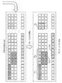
図2Aは、代表的な実施形態に従って、センサの配置を決定する建物レイアウトの図解である。 FIG. 2A is an illustration of a building layout that determines the placement of sensors according to a typical embodiment.
図2Aは、例となる実施形態の概略図を表す。図2A中、アルゴリズム的枠組みは、ホームモニタリングのためのマルチセンサ、マルチモーダル設置について論じる。アルゴリズムは、センサによって捕捉されたローデータのアクティビティ特有のストリームを受け取り、データストリームの高度な抽象概念を構成する。次いで、センサデータの結果として得られた抽象概念は、ADL及びIADLを正確に捕捉することに顕著な個々のセンサを決定するために使用される。更に、提案されるアルゴリズムは、アクティビティの相関関係又はシーケンスがADL及びIADLを捕捉するために重要であるセンサの対を識別する。例えば、寝室からバスルームまでの歩行行動をモニタするために、廊下センサ及びバスルーム扉センサのアクティビティの相関関係及びシーケンスは、トイレ行動の正確な検出にとって顕著である。廊下センサ及びバスルーム扉センサは、廊下での移動又はバスルーム扉の開閉などの特定のアクティビティを検出することを特に意図した場所に設置され得る。アクティビティ特有のストリームの対象であり得るアクティビティの他の例には、転倒又は歩行がある。 FIG. 2A shows a schematic diagram of an exemplary embodiment. In FIG. 2A, the algorithmic framework discusses multi-sensor, multi-modal installation for home monitoring. The algorithm receives an activity-specific stream of raw data captured by the sensor and constitutes a high-level abstraction of the data stream. The abstraction obtained as a result of the sensor data is then used to determine the individual sensors that are prominent in accurately capturing ADL and IADL. In addition, the proposed algorithm identifies sensor pairs for which activity correlations or sequences are important for capturing ADL and IADL. For example, to monitor walking behavior from bedroom to bathroom, the correlation and sequence of activity of corridor sensors and bathroom door sensors is significant for accurate detection of toilet behavior. Corridor sensors and bathroom door sensors may be installed in locations specifically intended to detect certain activities such as movement in the hallway or opening and closing of bathroom doors. Another example of an activity that can be the subject of an activity-specific stream is a fall or walk.
本明細書で開示される特徴は、マルチセンサ/マルチモーダル(周囲圧力及び動きセンサ、ビジョンセンサ)ホームモニタリングシステムの設置フェーズにおいて、種々のユーザシナリオをシミュレーションし、ユーザのアクティビティの最適なモニタリングのためのセンサの最小セット及びそれらの配置を決定するために使用され得る。更に、ユーザ特有の要因(例えば、体格)及びフロアプランの仕様は、ユーザを意識したセンサの更なる組を識別するためにモデリングにおいて組み込まれ得る。そのようなものとして、本明細書で開示される特徴は、ユーザごとに別々にホームモニタリングソリューションを調整することを可能にし、見返りとして、ユーザを意識した正確なホームモニタリングソリューションを促進することを助ける。提案される顕著なセンサ/チャネルの識別は、次の項で詳細に記載される。例えば、図2Aの左に図示されるように、初期のセンサは、レイアウトのあちこちに様々な位置で設置され得る。 The features disclosed herein are for the optimal monitoring of user activity by simulating various user scenarios during the installation phase of a multi-sensor / multi-modal (ambient pressure and motion sensor, vision sensor) home monitoring system. Can be used to determine the minimum set of sensors and their placement. In addition, user-specific factors (eg, physique) and floor plan specifications can be incorporated into the modeling to identify additional sets of user-aware sensors. As such, the features disclosed herein allow the home monitoring solution to be tailored separately for each user, and in return help promote a user-aware and accurate home monitoring solution. .. The proposed prominent sensor / channel identification is described in detail in the next section. For example, as illustrated on the left in FIG. 2A, early sensors can be installed at various locations throughout the layout.
ローセンサデータは、関心のある特定のイベント又はアクティビティを認識するための最小限の数のセンサ及び必要とされるセンサ配置を決定するために取得及び使用され得る。図2の右側には、関心のあるアクティビティを検出するための識別された顕著なセンサ及びチャネル対が概略的に表されている(破線により表されており、破線の太さは、センサの相対重み又は重要度に対応する)。例として、図2Aに表されているように、寝室からバスルームへの歩行行動をモニタするために、ホールセンサ及びバスルーム扉センサのアクティビティの相関関係及びシーケンスは、手洗い所行動の正確な検出にとって顕著であり得る。周囲センサは、ある場所の周りに設置されたセンサを含み得るが、日常生活のアクティビティはまた、ウェアラブルセンサを用いてもモニタされ得る。使用され得る周囲センサの例は、制限なしに、次を含む:
・赤外線センサ又はSONARセンサなどの動きセンサ
・温度センサ
・湿度センサ
・光センサ
・電気センサ
・圧力センサ
・セキュリティカメラなどのカメラセンサ
Low sensor data can be acquired and used to determine the minimum number of sensors and required sensor placement to recognize a particular event or activity of interest. On the right side of FIG. 2, the identified prominent sensors and channel pairs for detecting the activity of interest are schematically represented (represented by a dashed line, where the dashed line thickness is relative to the sensor. Corresponds to weight or importance). As an example, as shown in FIG. 2A, to monitor bedroom-to-bathroom walking behavior, the correlation and sequence of hall sensor and bathroom door sensor activity is an accurate detection of hand wash behavior. Can be noticeable for. Peripheral sensors can include sensors installed around a location, but activities in daily life can also be monitored using wearable sensors. Examples of ambient sensors that can be used include, without limitation:
・ Motion sensor such as infrared sensor or SONAR sensor ・ Temperature sensor ・ Humidity sensor ・ Optical sensor ・ Electrical sensor ・ Pressure sensor ・ Camera sensor such as security camera
動きセンサは、赤外線光の経路内にある障害物の有無を検出する2値バイナリセンサであってよい。例えば、赤外線動きセンサは、赤外線動きセンサの前にある対象物を検出し得る。動きセンサは、例えば、扉の開閉の動きを検出してよい。湿度センサは、例えば、失禁、又は誰かが入浴すること若しくは又はシャワーを浴びることを検出してよい。電気センサは、どれくらい長くテレビが点いているか、どれくらい長く明かりが点いているか、及び/又は電気デバイスの他の特性などの家電利用を検出してよい。圧力センサは、例えば、マットレスの中又は下に設置される場合に寝ている人の姿勢を検出してよく、姿勢を調整するよう看護スタッフに警告するために使用され得る。 The motion sensor may be a binary binary sensor that detects the presence or absence of an obstacle in the path of infrared light. For example, an infrared motion sensor may detect an object in front of the infrared motion sensor. The motion sensor may detect, for example, the opening / closing motion of the door. Humidity sensors may detect, for example, incontinence, or someone taking a bath or shower. The electrical sensor may detect how long the television has been on, how long the light has been on, and / or the use of appliances such as other characteristics of the electrical device. Pressure sensors may be used, for example, to detect the posture of a sleeping person when installed in or under a mattress and may be used to warn nursing staff to adjust the posture.
図2に記載される様々なセンサは、周囲圧力センサ、動きセンサ、ビジョンセンサ、及び/又は同様のもののようなマルチセンサ、マルチモーダルセンサを含んでよい。例えば、本明細書中での第1センサとの言及は、第1センサグループに対してであってよく、本明細書での第2センサとの言及は、第2センサグループに対してであってよい。第1センサグループ及び第2センサグループの中の各センサは、同じタイプ(モード)の特性を検知してよい。その上、第1センサグループ及び第2センサグループの中の異なるセンサは、異なるタイプ(モード)の特性を検知してよい。 The various sensors described in FIG. 2 may include ambient pressure sensors, motion sensors, vision sensors, and / or multi-sensors, multi-modal sensors such as the like. For example, the reference to the first sensor in the present specification may refer to the first sensor group, and the reference to the second sensor in the present specification refers to the second sensor group. It's okay. Each sensor in the first sensor group and the second sensor group may detect the same type (mode) of characteristics. Moreover, different sensors in the first sensor group and the second sensor group may detect different types (modes) of characteristics.
図2Aの実施形態では、センサの配置は、センサの数及び位置を含んでよい。位置は、扉、窓、及び引き出しなどの、センサ近くの他の要素(非センサ)のような特性によって識別されてよい。位置は、特定のタイプの部屋又は台所、バスルーム、ホール、地下室などの建物内の他の空間によって識別されてもよい。本明細書で記載されるように最適なセンサ構成の決定において使用されるローデータストリームを超えて、位置などの他の変数は、測定様式又はバイナリ形式のどちらかで使用されてもよい。測定様式は、制限なしに、例えば、身長測定、体重測定、BMI測定、床から天井までの距離、部屋面積、部屋の長さ/幅測定、湿度測定、温度測定、及び/又は同様のものを含む。バイナリ形式は、例えば、ペットの存在(Y/N)、閾値より上/下の高さ(Y/N)、現在の季節が夏であるかどうかと言った季節的存在(Y/N)及び/又は同様のものを含んでよい。 In the embodiment of FIG. 2A, the sensor arrangement may include the number and location of the sensors. Locations may be identified by characteristics such as other elements (non-sensors) near the sensor, such as doors, windows, and drawers. The location may be identified by a particular type of room or other space in the building such as a kitchen, bathroom, hall, basement. Beyond the raw data stream used in determining the optimal sensor configuration as described herein, other variables such as position may be used in either measurement mode or binary format. Measurement styles are unlimited, for example, height measurement, weight measurement, BMI measurement, floor-to-ceiling distance, room area, room length / width measurement, humidity measurement, temperature measurement, and / or similar. include. The binary format is, for example, the presence of pets (Y / N), the height above / below the threshold (Y / N), the seasonal presence such as whether the current season is summer (Y / N) and / Or similar may be included.
図2Aの実施形態では、最適なセンサ/チャネルセット配置は、ユーザのADLを検知するよう居住様態について識別され得る。左側の破線は、最適なセンサ配置を識別するようアルゴリズムに従うために、本明細書に記載されるコントローラに供給されるローセンサデータのストリームを示す。図2Aの右側には、識別された顕著なセンサ及びチャネル対が破線として示されている。右側にある破線の太さは、関心のあるアクティビティを検出するための対応するセンサの重要度を示す。右側のセンサ間の実線は、関心のあるアクティビティを認識するための識別された顕著なペアワイズ相関を示す。 In the embodiment of FIG. 2A, the optimal sensor / channel set arrangement can be identified for the living mode to detect the user's ADL. The dashed line on the left shows the stream of raw sensor data supplied to the controllers described herein to follow the algorithm to identify the optimal sensor placement. On the right side of FIG. 2A, the identified prominent sensor and channel pairs are shown as dashed lines. The dashed line thickness on the right indicates the importance of the corresponding sensor to detect the activity of interest. The solid line between the sensors on the right shows the identified prominent pairwise correlation for recognizing the activity of interest.
図2Aの実施形態についてのコンテキスト例は、家のあちこちに置かれたセンサである。図2Aの実施形態についての他のコンテキスト例は、養護施設のあちこちに置かれたセンサである。 An example context for the embodiment of FIG. 2A is sensors placed around the house. Another context example for the embodiment of FIG. 2A is sensors placed around the nursing home.
図2Bは、代表的な実施形態に従って、センサの配置を決定するモデルの図解である。 FIG. 2B is an illustration of a model that determines the placement of sensors according to a typical embodiment.
図2Bは、多変量な時系列の観察結果(センサデータストリーム)の生成/弁別の複合的な抽象概念を取得する顕著なセンサ及び/又はチャネルの識別のためのモデルの例を表す。本明細書で記載される1以上のモデルは、確率論的グラフィカルモデルを指し得る。例えば、図2Bに表されているように、設置されているセンサを介して受け取られたローデータは、確率的モデル又は動的ベイジアンネットワーク(例えば、別個の隠れマルコフモデル(HMM))において、アクティビティ特有の時系列観察結果として符号化されてよい。 FIG. 2B represents an example of a model for prominent sensor and / or channel identification to obtain a complex abstraction of generation / discrimination of multivariate time series observations (sensor data streams). One or more models described herein can refer to probabilistic graphical models. For example, as shown in FIG. 2B, raw data received through an installed sensor is active in a stochastic model or a dynamic Bayesian network (eg, a separate Hidden Markov Model (HMM)). It may be encoded as a peculiar time series observation result.
このようにして、センサデータストリームの時間情報は、動的な確率的プロセスとして埋め込まれ得る。次に、センサデータストリームは、結果として得られたアクティビティ特有のモデル(HMM)の事後分布(posterior)空間において投影され、従って、系統的な時系列表現のためのモデル(例えば、HMM)を別な目的のために再利用し得る。各センサによって検知されたアクティビティの各状態を通る経過は、いずれか1つの状態が次に同じ又は他の状態を引き起こす確率を決定するために蓄積及び解析され得る。次いで、アクティビティ特有の確率分布間の距離が計算され得る。それらの、結果として得られた確率距離は、センサデータの共有される確率表現を得るよう集約され得る。結果として得られた共有される確率空間の次元は、グループLASSO回帰を用いて、異なるイベント及びアクティビティを区別することに対するそれらの関連性に従って、自動的に重み付けられ得る。グループLASSOは、グループLASSO罰則付き多項分布ロジスティック回帰モデル、又はグループLASSO罰則付き二項ロジスティック回帰モデルを適用してよい。追加のセンサデータは、最初のモデリングに続いてセンサから受け取られ、次いで、いずれかの特定のモデルが追加のセンサデータを生成した尤度を決定するよう適用され得る。決定された尤度は、第1センサ及び第2センサと関連付けられる。そして、センサの最小セットは、決定された重みに基づいて、関心のあるイベント及びアクティビティを追跡及び検出するのに最も顕著なものとして識別され得る。センサの最小セットは、最初のセンサのサブセットなどの、最初のセンサからの最小限のセンサのグループであってよい。 In this way, the time information in the sensor data stream can be embedded as a dynamic stochastic process. The sensor data stream is then projected in the posterior space of the resulting activity-specific model (HMM), thus separating the model for systematic time series representation (eg, HMM). Can be reused for various purposes. The course of activity detected by each sensor through each state can be accumulated and analyzed to determine the probability that any one state will then cause the same or other state. The distance between activity-specific probability distributions can then be calculated. The resulting stochastic distances can be aggregated to obtain a shared probabilistic representation of the sensor data. The resulting shared probability space dimensions can be automatically weighted according to their relevance to distinguishing different events and activities using group Lasso regression. The group Lasso may apply a group Lasso penalized multinomial distribution logistic regression model or a group Lasso penalized binomial logistic regression model. Additional sensor data may be received from the sensor following the initial modeling and then applied to determine the likelihood that any particular model generated the additional sensor data. The determined likelihood is associated with the first sensor and the second sensor. The minimum set of sensors can then be identified as the most prominent for tracking and detecting events and activities of interest based on the determined weights. The minimum set of sensors may be a minimal group of sensors from the first sensor, such as a subset of the first sensor.
図2Bに表されているこのアプローチは、多変量の時系列観察結果の隠れマルコフモデル及びフォワードアルゴリズムによって推定される事後確率(又は事後分布間の対称なカルバック・ライブラー・ダイバージェンスに基づき構成されるアフィニティ行列)に対してグループLASSO罰則を適用してよい。このようにして、グループLASSO罰則付き多項ロジスティック回帰モデルは、各グループがセンサの事後分布に対応している生成ネットワークの事後分布に対して適用される。従って、システムは、対象のイベント、アクティビティ及び/又は現象を捕捉するために必要とされるセンサの数及びそれらの配置を最適化するための系統的枠組みを提供し得る。そして、このメソッドロジは、観察結果が固定長である必要があるが、自然のままの設定ではデータが通常は固定長でないというローセンサデータによる問題を抱えていた従来の特徴選択技術の限界の1つを解消する。 This approach, represented in FIG. 2B, is constructed on the basis of posterior probabilities (or symmetric Kullback-Leibler divergence between posterior distributions) estimated by hidden Markov models and forward algorithms of multivariate time series observations. Group LASTO penalties may be applied to the affinity matrix). In this way, the group Lasso penalized multinomial logistic regression model is applied to the posterior distribution of the generated network, where each group corresponds to the posterior distribution of the sensor. Thus, the system may provide a systematic framework for optimizing the number of sensors required to capture the event, activity and / or phenomenon of interest and their placement. And this method log has the limitation of the conventional feature selection technology, which has a problem with low sensor data that the observation result needs to be fixed length, but the data is not usually fixed length in the natural setting. Eliminate one.
ADLの周囲センサ配置に関して、マルチモーダル、多変量の時系列観察結果が多数存在し得るが、これらの観察結果の全てが、ADLアクティビティを検知するために使用されるセンサに関わる関心のあるアクティビティを区別することに関係があるわけではない。無関係な時系列データの存在は、関心のあるアクティビティに最も顕著なデータストリームを分かりにくくすること、予測的及び弁別的解析を妨げること、並びに計算ストレージ及び保守費用を増すことといったいくつかの課題を引き起こす。しかし、本明細書で記載されるシステム及び方法は、関心のあるアクティビティを区別するのに顕著な時系列モダリティ及びチャネルを識別する。 There can be many multimodal, multivariate time series observations regarding the placement of sensors around the ADL, but all of these observations are of interest to the sensors used to detect ADL activity. It has nothing to do with making a distinction. The presence of irrelevant time series data presents several challenges, such as obscuring the most prominent data stream for the activity of interest, hindering predictive and discriminative analysis, and increasing computational storage and maintenance costs. cause. However, the systems and methods described herein identify prominent time series modality and channels to distinguish between activities of interest.
図2Bに関して上述されたように、センサデータの確率論的な生成的/弁別的符号化は、規則化され得る。イベント特有のデータストリームは、別個の生成的動的ベイジアンネットワーク(例えば、隠れマルコフモデル)において符号化されてよい。グループLASSO罰則付き多項ロジスティック回帰は、各グループがセンサの事後分布に対応している生成ネットワークの事後分布に対して実行されてよい。生活空間におけるユーザ生活に特有の詳細(例えば、ユーザニーズ及び体格)は、よりユーザに特有のセンサ配置を識別するために回帰に組み込まれ得る。アプローチは、イベント特有のデータストリームの時系列及び可変長の性質を考慮し、マルチモーダルセンシング設定における任意数の従属的な又は独立したセンサに適用され得る。図2Bで見られるに、ADLを検出することにとって最も顕著なセンサの最小セットを識別することは、効率的な、低コストの、正確なADL追跡及びモニタリング技術を促進することを助ける。結果として得られたセンサの最小セットは、例えば、ホームモニタリングのために、周囲センシング設定において日常生活のアクティビティを追跡するためのセンサ配置を最適化するために使用され得る。 As mentioned above with respect to FIG. 2B, the probabilistic generative / distinctive coding of the sensor data can be regularized. The event-specific data stream may be encoded in a separate generative dynamic Bayesian network (eg, a hidden Markov model). Group Lasso penalized multinomial logistic regression may be performed on the posterior distribution of the generated network, where each group corresponds to the posterior distribution of the sensor. Details specific to the user's life in the living space (eg, user needs and physique) can be incorporated into the regression to identify more user-specific sensor arrangements. The approach can be applied to any number of dependent or independent sensors in a multimodal sensing configuration, taking into account the time series and variable length nature of the event-specific data stream. Identifying the smallest set of sensors most prominent for detecting ADL, as seen in FIG. 2B, helps facilitate efficient, low cost, accurate ADL tracking and monitoring techniques. The resulting minimum set of sensors can be used, for example, for home monitoring, to optimize sensor placement for tracking activities in daily life in ambient sensing settings.
顕著なセンサ/チャネルの識別アプローチのための図2B中のフローの他の説明は、色分けされたグループがセンサ特有の変数に対応し得ることである。センサ特有の変数の中で、関心のあるイベントに関係があるものは、使用されるべきセンサの最小セットを反映するものとして識別され返され得る。m個の最初のセンサは、S1乃至Smと示される。λm,kは、m番目のセンサにより捕捉されたk番目のアクティビティを符号化するHMMモデルを示す。図2B中、P(Om|λm,k)は、λm,kによって生成される、m番目のセンサからのストリームデータ(Om)の事後分布であり、事後分布は、ここでは、条件付き尤度又は確率と同義であるGnは、n番目のセンサに対応するHMMパラメータの組である。 Another description of the flow in FIG. 2B for a prominent sensor / channel identification approach is that color-coded groups can correspond to sensor-specific variables. Sensor-specific variables that relate to the event of interest can be identified and returned as reflecting the minimum set of sensors to be used. The first m sensors are designated S1 to Sm. λ m, k indicates an HMM model that encodes the kth activity captured by the mth sensor. In FIG. 2B, P (Om | λ m, k ) is the posterior distribution of the stream data (Om) from the mth sensor generated by λ m, k, and the posterior distribution is here conditional. Gn , which is synonymous with likelihood or probability, is a set of HMM parameters corresponding to the nth sensor.
最後に、図2B中のフローの出力は、センサによってモニタされるアクティビティへのセンサの関連性を識別するために使用され得る。センサがセンサによって検知されるアクティビティを反映する状態の経過を検知する場合に、フローは、各アクティビティに対する各センサの関連性を識別することを助ける。よって、センサの最初のグループが、第1アクティビティ及び第2アクティビティをモニタする第1センサ及び第2センサを含む場合に、図2B中のフローは、どのセンサが含まれるかと、どのセンサが空間をモニタするために使用される配置から除かれるかとを決定するためであることができる。よって、第1センサ及び第2センサを含む最初のセットのうち、第1センサ及び第2センサのうちの一方は、アクティビティへの関連性に基づいて配置に含められてよく、第1センサ及び第2センサのうちの他方は、アクティビティへの関連性に基づいてセンサの配置において除かれてよい。 Finally, the output of the flow in FIG. 2B can be used to identify the sensor's relevance to the activity monitored by the sensor. Flows help identify the relevance of each sensor to each activity when the sensor detects the course of a state that reflects the activity detected by the sensor. Thus, if the first group of sensors includes a first sensor and a second sensor that monitor the first and second activities, the flow in FIG. 2B shows which sensor is included and which sensor is in space. It can be to determine if it is excluded from the arrangement used for monitoring. Thus, of the first set including the first sensor and the second sensor, one of the first sensor and the second sensor may be included in the arrangement based on its relevance to activity, the first sensor and the second sensor. The other of the two sensors may be excluded in the placement of the sensors based on their relevance to activity.
図2Cは、代表的な実施形態に従ってセンサの配置を決定する生理的レイアウトの図解である。 FIG. 2C is an illustration of a physiological layout that determines the placement of sensors according to typical embodiments.
例として、図2Cは、ハンドジェスチャ認識において使用される生理的センサのための最適なセンサ構成を取得することを表す。この例で、ハンドジェスチャは、腕及び前腕で捕捉された関連する筋電図(EMG)アクティビティから検出され得る。この例では、概して生理的センサ構成において、いくつかのセンサが特定のイベント及び/又はアクティビティを検出するために必要とされるかと、異なるイベント(例えば、ハンドジェスチャ)を区別するのを助けるようどこにセンサは位置付けられるべきかとを識別することが重要であり得る。本明細書で記載されるアプローチは、確率論的な、個人間のタイミング及び位相変動を考慮し得る。 As an example, FIG. 2C represents acquiring the optimal sensor configuration for a physiological sensor used in hand gesture recognition. In this example, hand gestures can be detected from associated electromyographic (EMG) activity captured on the arm and forearm. In this example, generally in a physiological sensor configuration, where some sensors are needed to detect a particular event and / or activity and where to help distinguish between different events (eg, hand gestures). It can be important to identify whether the sensor should be positioned. The approaches described herein can take into account probabilistic, inter-individual timing and phase variability.
マルチモーダル/多変量の時系列観察結果を鑑み、本明細書で記載されるシステム及び方法は、異なる分類の観察結果を区別することに最も顕著な時系列変数/モダリティの最小セットを識別し得る。例えば、図2Cに表されているように、上の図に表されているセンサの数を、下の図の白抜きブロックによって定義されるセンサに減らすよう、次のプロシージャが使用され得る。 Given the multimodal / multivariate time series observations, the systems and methods described herein may identify the smallest set of time series variables / modality that is most prominent in distinguishing between different classifications of observations. .. For example, the following procedure may be used to reduce the number of sensors shown in the upper figure to the sensors defined by the white blocks in the figure below, as shown in FIG. 2C.
最初に、多変量の時系列観察結果は、確率論的な生成/弁別ハイブリッドモデルに符号化されてよい。次いで、共有される確率的表現が生成されてよく、観察結果は、確率論的モデル間のペアワイズ距離に関して表現される。結果として得られた確率論的モデルのパラメータは、次いで、共有される確率空間においてグループLASSO罰則付き多項ロジスティック回帰モデルを用いて重み付けされてよく、各グループがセンサ特有の距離(アクティビティごとの、あるセンサと残りのセンサとの間の事後分布距離)に対応する。そして、最後に、システムは、重み付けされたパラメータに基づいて顕著なセンサチャネルを決定し、削減されたセンサセットに基づいて観察結果を分類し得る。 First, multivariate time series observations may be coded into a stochastic generation / discrimination hybrid model. A shared probabilistic representation may then be generated and the observations are represented with respect to the pairwise distance between the stochastic models. The parameters of the resulting stochastic model may then be weighted using a multinomial logistic regression model with group LASTO penalties in a shared probability space, where each group has a sensor-specific distance (per activity). It corresponds to the posterior distribution distance between the sensor and the rest of the sensors). And finally, the system may determine prominent sensor channels based on weighted parameters and classify observations based on a reduced set of sensors.
生理的センシング技術のための最適なセンサ構成を決定するシステム及び方法は、特定の身長、体重、及び/又は体格のユーザのための一般的なセンサ構成を決定するために使用されてよく、あるいは、システム及び方法は、特定のユーザ特徴(身長、体重、BMI、生理的特性、ユーザ診断及び/又は同様のもの)に基づいて特定のユーザのための最適なセンサ配置を決定するために使用されてよい。 Systems and methods for determining optimal sensor configurations for physiological sensing techniques may be used or used to determine general sensor configurations for users of a particular height, weight, and / or physique. , Systems and methods are used to determine the optimal sensor placement for a particular user based on the particular user characteristics (height, weight, BMI, physiological characteristics, user diagnostics and / or similar). It's okay.
本明細書で記載されるシステム及び方法は、センサの数及び配置を決定し得るだけでなく、センサタイプ(ECG、PPG、加速度計、ジャイロスコープ、及び/又は同様のもの)も決定し得る。 The systems and methods described herein can not only determine the number and placement of sensors, but also the sensor type (ECG, PPG, accelerometer, gyroscope, and / or similar).
周囲センシング技術の最適な配置と同様に、生理的センシング技術の構成のための、本明細書で記載される方法は、図2Bに関して上述された方法を含んでよい。生理的センシング技術のために図2Bのメソッドロジを用いると、周囲センシング技術に特有の様々な制約が課される可能性がある。例えば、制約は、センサの組のメンバーが常に一緒に選択されることを確かにするよう定められることがある(例えば、長指屈筋と表在指屈筋の両方が関与して、親指を曲げ、指を曲げて拳のジェスチャーを作る)。そのようなものとして、提案されるアプローチは、相互作用するチャネルを、分類タスクに対するそれらの集合的な顕著性に基づいて一緒に選択(除外)するよう強いられる。 Similar to the optimal placement of perimeter sensing techniques, the methods described herein for the configuration of physiological sensing techniques may include the methods described above with respect to FIG. 2B. Using the method log of FIG. 2B for physiological sensing techniques may impose various constraints specific to ambient sensing techniques. For example, constraints may be defined to ensure that members of a set of sensors are always selected together (eg, bending the thumb, involving both the flexor digitorum longus and superficial finger flexors, Bend your fingers to make a fist gesture). As such, the proposed approach is forced to select (exclude) interacting channels together based on their collective saliency to the classification task.
センサ組み合わせに関する演繹的情報は、例えば、ユーザがペットと一緒に生活しているかどうかといった、世帯配置の詳細を含んでよい。個人の世帯に特有であるこの種の情報は、センサの最初の組を配置するために使用され得る。例えば、ユーザがペットと一緒に生活している場合に、廊下でのユーザの動きの検出は、1フィート及び5フィートの高さにある動きセンサが両方とも同時に作動することを求められ得る。これは、1フィートでのセンサの作動がもっぱらペットによってトリガされ得るからである。センサ組み合わせに関する演繹的情報が利用可能である場合には、図2Bに表されているアプローチは、センサの組み合わせ(例えば、センサトリプレット)を、ADLを検出することに対するそれらの集合的な顕著性に基づいて選択(除外)するために、演繹的情報を組み込むことができる。更に、アプローチは、よりユーザを意識したセンサの組及びそれらの配置を識別するために、ユーザの体格(例えば、身長)に関する情報を組み込むことができる。 Deductive information about the sensor combination may include household placement details, such as whether the user is living with a pet. This type of information, which is unique to an individual household, can be used to place the first set of sensors. For example, if the user is living with a pet, detection of the user's movement in the corridor may require that both motion sensors at heights of 1 foot and 5 feet be activated at the same time. This is because the activation of the sensor at 1 foot can be triggered exclusively by the pet. If deductive information about the sensor combinations is available, the approach shown in FIG. 2B is to make the sensor combinations (eg, sensor triplets) their collective saliency to detect ADL. Deductive information can be incorporated for selection (exclusion) based on. In addition, the approach can incorporate information about the user's physique (eg, height) to identify more user-aware sets of sensors and their placement.
センサ組み合わせ及び/又は環境に関する情報が最終設定の前に利用可能である場合には、それらのデータ点は計算プロセスに含まれてよい。例として、ユーザがペットと一緒に生活している場合に、廊下でのユーザの動きを検出するために、2つの動きセンサが必要とされ得、1つの低い高さ(例えば、地面から1フィート)にあり、もう1つはより高いところ(例えば、地面から5フィート)にあり、これによって、センサは、同時に作動されるよう求められ得る。 If information about the sensor combination and / or environment is available prior to final setup, those data points may be included in the calculation process. As an example, when a user lives with a pet, two motion sensors may be needed to detect the user's movement in the corridor, one low height (eg, one foot above the ground). ) And the other higher (eg, 5 feet above the ground), which may require the sensor to be activated simultaneously.
最初のローセンサデータが利用不可能である場合に、画像レイアウト、ユーザデータ、及び/又は他の既知のデータが、センサ配置をモデリングするために使用されてよく、これによって、ローセンサデータは、画像レイアウト、ユーザデータ、及び/又は他の既知のデータソースを用いてシミュレーションされ得る。 Image layout, user data, and / or other known data may be used to model the sensor placement if the initial raw sensor data is not available, thereby causing the raw sensor data to be. It can be simulated using image layouts, user data, and / or other known data sources.
図3Aは、代表的な実施形態に従って、センサの配置を決定するコントローラの図解である。 FIG. 3A is an illustration of a controller that determines the placement of sensors according to a typical embodiment.
図3A中、コントローラ380は、命令を記憶しているメモリ330と、命令を実行するプロセッサ320とを含む。コントローラ380は、モバイルコンピュータ又はタブレットを含む様々なデバイス、システム及び配置において提供されてよい。プロセッサ320は、本明細書で記載される方法の部分又は全部を実施するよう命令を実行してよい。その上、コントローラ380は、方法が本質的に、複数組のメモリ/プロセッサの組み合わせを必要とする分散様態で実施される場合のように、いくつかのデバイスの間で分配されてもよい。
In FIG. 3A, the controller 380 includes a
図3Bは、代表的な実施形態に従って、センサの配置を決定するシステムの図解である。 FIG. 3B is an illustration of a system that determines the placement of sensors according to a typical embodiment.
本明細書で記載される方法及び/又はモデルを実行するシステムは、例えば、図3Bに表されているようなハードウェアコンポーネントのシステム300を含んでよい。例えば、システム300は、ホストデバイスなどのデバイスであってよい。図示されるように、システム300は、1つ以上のシステムバス310を介して相互接続されているプロセッサ320、メモリ330、ユーザインターフェース340、通信インターフェース350、及びストレージ360を含んでよい。図3Bは、いくつかの点で、抽象概念を構成し、システム300のコンポーネントの実際の編成は、表されているよりも複雑であり得ることが理解されるだろう。
A system that implements the methods and / or models described herein may include, for example, a
プロセッサ320は、メモリ330若しくはストレージ360に記憶されている命令を実行すること、又はデータを別なふうに処理することが可能な如何なるハードウェアデバイスであってもよい。そのようなものとして、プロセッサは、マイクロプロセッサ、フィールドプログラマブルゲートアレイ(FPGA)、特定用途向け集積回路(ASIC)、又は他の同様のデバイスを含んでよい。
メモリ330は、例えば、L1、L2、若しくはL3キャッシュ又はシステムメモリなどの様々なメモリを含んでよい。そのようなものとして、メモリ330は、静的ランダムアクセスメモリ(RAM)、動的RAM(DRAM)、フラッシュメモリ、リードオンリーメモリ(ROM)、又は他の同様のメモリデバイスを含んでよい。明らかなように、プロセッサが、ハードウェアにおいて本明細書で記載される機能の1つ以上を実施する1つ以上のASIC(又は他の処理デバイス)を含む実施形態では、他の実施形態でそのような機能に対応すると記載されるソフトウェアは、省略されてよい。
The
ユーザインターフェース340は、管理者、臨床医、技術者、ユーザ、及び/又は医師などのユーザとのやりとりを可能にする1つ以上のデバイスを含んでよい。例えば、ユーザインターフェース340は、ユーザコマンドを受け取るディスプレイ、マウス、及びキーボードを含んでよい。いくつかの実施形態で、ユーザインターフェース340は、通信インターフェース350を介して遠隔の端末へ提供され得るコマンドラインインターフェース又はグラフィカルユーザインターフェースを含んでもよい。
The
通信インターフェース350は、他のハードウェアデバイスとの通信を可能にする1つ以上のデバイスを含んでよい。例えば、通信インターフェース350は、イーサネット(登録商標)プロトコルに従って通信するよう構成されるネットワークインターフェースカード(NIC)を含んでよい。その上、通信インターフェース350は、TCP/IPプロトコルに従う通信のためにTCP/IPスタックを実装してもよい。通信インターフェース350のための様々な代替又は追加のハードウェア又は構成は、明らかである。
The
ストレージ360は、リードオンリーメモリ(ROM)、ランダムアクセスメモリ(RAM)、磁気ディスク記憶媒体、光記憶媒体、フラッシュメモリデバイス、又は同様の記憶媒体などの1つ以上のマシン読み出し可能な記憶媒体を含んでよい。様々な実施形態で、ストレージ360は、プロセッサ320による実行のための命令、又はプロセッサが作用し得るデータを記憶してよい。例えば、ストレージ360は、周囲センシング技術や生理的センシング技術に関連したデータ(例えば、ローセンサデータ)や、例えば、時系列符号化、確率分布距離計算、共有される確率的表現、及びグループLASSO最適化からのデータを含む、本明細書で記載されるメソッドロジのいずれかの段階に関連したデータを記憶し得る。システム300が本明細書で記載されるプロシージャを実施する場合に、ストレージ360は、オペレーティングシステム361、時系列符号化エンジン362、確率分布距離エンジン363、共有確率表現エンジン364、及びグループLASSO365を含んでよい。時系列符号化エンジン362は、アクティビティ特有の時系列観察結果を符号化するための実行可能命令を格納してよい。確率分布距離エンジン363は、結果として得られたアクティビティ/イベント特有のモデルの事後分布空間においてセンサデータストリームを投影し、アクティビティ特有の確率分布間の距離を計算するための実行可能命令を格納してよい。共有確率表現エンジン364は、センサデータの共有される確率的表現を得るよう、結果として得られた確率距離を集約するための実行可能命令を格納してよい。グループLASSO365は、異なるイベント及びアクティビティを区別するよう、結果として得られた共有される確率空間の次元をそれらの関連性に従って重み付けし、関心のあるイベント又はアクティビティを追跡及び検出することにとって最も顕著なセンサの最小セットを識別するための実行可能命令を格納してよい。ストレージ360は、本明細書で記載される機能を実行するために必要な更なるソフトウェアコンポーネントを記憶してよい。また、そのようなソフトウェアコンポーネントは、システム300の動作を制御し得る。
Storage 360 includes one or more machine-readable storage media such as read-only memory (ROM), random access memory (RAM), magnetic disk storage media, optical storage media, flash memory devices, or similar storage media. It's fine. In various embodiments, the storage 360 may store instructions for execution by the
明らかなように、ストレージ360に記憶されると記載されている様々な情報は、追加的に、又は代替的に、メモリ330に記憶されてもよい。これに関連して、メモリ330はまた、「記憶デバイス」を構成すると見なされてもよく、ストレージ360は、「メモリ」と見なされてよい。様々な他の配置は明らかである。更に、メモリ330及びストレージ360は両方とも、「非一時的なマシン読み出し可能な媒体」であると見なされてもよい。本明細書で使用されるように、語「非一時的」は、一時的な信号を除外し、揮発性メモリ及び不揮発性メモリの両方を含む全ての形態のストレージを含むと理解される。
As will be apparent, the various information described as stored in storage 360 may be additionally or alternatively stored in
システム300は、夫々記載されているコンポーネントの1つを含むものとして示されているが、様々なコンポーネントが様々な実施形態で複製されてよい。例えば、プロセッサ320は、本明細書で記載される方法を独立して実行するよう構成されるか、あるいは、本明細書で記載される方法のステップ又はサブルーチンを実行するよう構成される複数のマイクロプロセッサを含んでよく、それにより、複数のプロセッサは、本明細書で記載される機能を達成するよう協働する。更に、システム300がクラウドコンピューティングシステムで実施される場合に、様々なハードウェアコンポーネントは別個の物理システムに属してよい。例えば、プロセッサ320は、第1サーバにある第1プロセッサと、第2サーバにある第2プロセッサとを含んでよい。
The
図4は、代表的な実施形態に従って、センサの配置を決定するプロセスを表す。 FIG. 4 represents a process of determining sensor placement according to a representative embodiment.
図4は、本明細書で記載される様々なシステムによって実行され得る方法400を表す。方法400は、ブロックS402から開始してよい。ブロックS404で、最初のセンサが設置される(例えば、図2A及び/又は図2Cのセンサ配置)。S404で設置されたセンサは、センサの第1の組と見なされてよい。方法400は、初期センサ配置を必要としなくてもよく、フロアプラン及び/若しくは部屋構成データ(例えば、天井高さ、対象物どうしの距離、壁の間の距離、扉フレームの高さ、照明家具の一、及び/又は同様のもの)並びに/又はユーザデータ及び/若しくは特性(例えば、身長、体重、BMI、ユーザ体格データ、ユーザバイタルサインデータ、ユーザ皮膚特性、ユーザ食習慣及び/又は栄養摂取情報及び/又は同様のもの)のような初期データ入力を必要としてもよい。
FIG. 4 represents a
ブロックS405で、センサの第1の組は、アクティビティの状態についてのローセンサデータを検知する。アクティビティは、通常、センサによって検知される人間のアクティビティである。アクティビティの例は、移動、呼吸、足踏み、会話、転倒、扉の開閉、窓の開閉、階段の上り下り、冷蔵庫又はキャビネットの開閉、などである。視覚、聴覚、嗅覚(化学物質の検出)、及び触覚を含む検知、及びアクティビティの例は、何が検知されるかに加えて、あらゆるセンサのタイプ及び設置に基づいて理解されるだろう。アクティビティの状態は、例えば、静寂から騒々しさへの変化、暗から明への変化、オフからオンへの変化、又はアクティビティの状態における他の2値変化などのセンサのステータスの違いを反映する。従って、状態は、時間1での状態1、時間2での状態1、時間3での状態1、時間4での状態2などのように、時間にわたる状態の経過である。加えて、状態は、センサが10若しくは100のレベル又は音響若しくは光の連続的な(離散的でない)観測のような、2よりも多い状態を検出するよう構成され得るということで、2値の可能性に限られない。
At block S405, the first set of sensors detects low sensor data about the state of activity. The activity is usually a human activity detected by a sensor. Examples of activities include moving, breathing, stepping, talking, falling, opening and closing doors, opening and closing windows, going up and down stairs, opening and closing refrigerators or cabinets, and so on. Examples of detection, including visual, auditory, odor (chemical detection), and tactile sensations, and activities will be understood based on all sensor types and installations, as well as what is detected. The activity state reflects differences in sensor status, such as a change from silence to noisy, a change from dark to light, a change from off to on, or another binary change in the state of activity. .. Therefore, the state is the passage of the state over time, such as
ブロックS406で、システムは、センサによって捕捉されたローデータのアクティビティ特有のストリームを受け取り、かつ/あるいはローデータのアクティビティ特有のストリームをモデリングしてよい。ローデータのアクティビティ特有のストリームは、時間にわたってセンサによって検知されたアクティビティの状態の伝搬に基づく。例えば、センサは、時間にわたって数十、数百、数千、又は数百万の状態を検知し、検知された状態をローデータとして連続的に、バッチにおいて、又はリクエストされたときにオンデマンドで検知してよい。 At block S406, the system may receive and / or model the activity-specific stream of raw data captured by the sensor. The activity-specific stream of raw data is based on the propagation of the state of activity detected by the sensor over time. For example, a sensor detects tens, hundreds, thousands, or millions of states over time, and the detected states are continuously raw data, in batches, or on demand when requested. It may be detected.
ブロックS407Aで、状態の経過の時系列の観察結果は、センサの第1の組の夫々からの夫々のアクティビティ特有のストリームについてローデータのための別個のモデルを用いて識別される。すなわち、ブロックS404で設置されたセンサの夫々は、ローデータを供給することができ、別個のモデルは、各センサによって検知された各アクティビティごとに適用され得る。よって、第1センサは、第1アクティビティについての状態の経過と、第2アクティビティについての状態の経過とを検知し、別個のモデルは、第1センサによって検知された第1アクティビティ及び第2アクティビティの夫々について適用され得る。第2センサが同じ第1アクティビティについての状態の経過及び同じ第2アクティビティについての状態の経過とを検知する場合に、更なる別個のモデルが、第2センサによって検知された第1アクティビティ及び第2アクティビティの夫々について起用され得る。モデルは、同じ又は異なった設定を有する同じモデルであってよく、それにより、異なるセンサについての(からの)夫々のアクティビティ特有のストリームの状態の時系列経過は、それらが、たとえ異なる入力設定が異なるアクティビティ特有のストリームに対して使用されるとしても、同じタイプのモデルによってモデリングされる点で、互換性がある。 At block S407A, time-series observations of the course of the state are identified using a separate model for raw data for each activity-specific stream from each of the first set of sensors. That is, each of the sensors installed in block S404 can supply raw data, and a separate model can be applied for each activity detected by each sensor. Therefore, the first sensor detects the progress of the state for the first activity and the progress of the state for the second activity, and the separate model is the progress of the first activity and the second activity detected by the first sensor. Can be applied for each. When the second sensor detects the progress of the state for the same first activity and the course of the state for the same second activity, a further separate model is the first activity and the second detected by the second sensor. Can be appointed for each activity. The model may be the same model with the same or different settings, so that the time series course of each activity-specific stream state (from) for different sensors will be such that they have different input settings. They are compatible in that they are modeled by the same type of model, even if they are used for streams specific to different activities.
ブロックS407Bで、状態の経過の時系列の観察結果は、夫々のアクティビティ特有の時系列についていずれか1つの状態からいずれかの他の状態への経過の相対量/ボリューム/数を決定するよう解析され得る。すなわち、任意の1つの時系列の観察結果で状態から状態への多数の経過が与えられた場合、解析は、それぞれが同じままであるか、又は可能な他の状態に遷移する回数を確認することであってよい。1つの状態から何らかの他の状態への経過の数の決定は、最初にカウントとして実行され、次に、状態からのどの遷移が最も可能性が高いかと、いずれか1つの状態が何らかの次の状態(すなわち、同じ状態又は何らかの異なる状態)に遷移する尤度とを示す比較として実行される。上述されたように、S407Bでの解析は、各センサによって検知された各アクティビティの状態の各時系列観察結果ごとに実行され得る。 In block S407B, the time-series observations of the state course are analyzed to determine the relative quantity / volume / number of the course from any one state to any other state for each activity-specific time series. Can be done. That is, if the observations of any one time series are given a large number of transitions from state to state, the analysis confirms the number of times each remains the same or transitions to other possible states. It may be that. Determining the number of transitions from one state to some other state is first performed as a count, then which transition from the state is most likely, and one state is some next state. It is performed as a comparison showing the likelihood of transitioning to (ie, the same state or some different state). As mentioned above, the analysis in S407B can be performed for each time series observation of the state of each activity detected by each sensor.
ブロックS408で、システムは、符号化されたアクティビティ特有の時系列の観察結果を別個のアクティビティ特有のモデルにおいて生成するために、アクティビティ特有の時系列の観察結果を別個のモデルにおいて符号化してよい。例えば、アクティビティ特有の時系列の観察結果は、別個の隠れマルコフモデル(HMM)において符号化されてよく、それによって、センサデータストリームの時間情報を動的な確率論的プロセスとして直接埋め込む。隠れマルコフモデルは、離散的な観察結果及び連続的な観察結果の両方を表し得る離散的な隠れ状態及び出力ユニットを有するベイジアンネットワークである。連続的なHMMは、N個の隠れ状態値の間で変化する隠れ状態変数によってダイナミクスが記述される確率論的プロセスとして、順次的な観察結果を符号化し得る。隠れ状態値の間の遷移は、N×Nの状態遷移行列によって表される遷移確率によって左右され得る。HMMの可観測レイヤは、隠れ状態値に夫々関連した出力ユニットから成ってよい。HMMは、M個のチャネルの多変量の観察結果をモデリングしてよい。各隠れ状態での出力の分布は、ガウス分布の混合を用いてモデリングされ得る。ガウス出力の混合は、観察結果の複数の級内モードがある場合に適切であり得る。 At block S408, the system may encode activity-specific time-series observations in a separate model in order to generate coded activity-specific time-series observations in a separate activity-specific model. For example, activity-specific time-series observations may be encoded in a separate Hidden Markov Model (HMM), thereby directly embedding the time information of the sensor data stream as a dynamic stochastic process. Hidden Markov models are Bayesian networks with discrete hidden states and output units that can represent both discrete and continuous observations. Continuous HMMs can encode sequential observations as a stochastic process in which the dynamics are described by hidden state variables that vary between N hidden state values. The transition between hidden state values can depend on the transition probabilities represented by the N × N state transition matrix. The observable layer of the HMM may consist of output units, each associated with a hidden state value. The HMM may model multivariate observations of M channels. The distribution of the output in each hidden state can be modeled using a mixture of Gaussian distributions. Mixing Gaussian outputs may be appropriate when there are multiple intraclass modes of observations.
左から右への(left-to-right)HMM構成は、開始点から終了点までしばしば進む周期的な運動及び他のデータ点の欠如を考慮するために使用されてよい。Kの分類のうちの1つに夫々属するN個の多変量時系列観察結果(x1からxN)を考えると、分類特有のHMMは、あらゆるチャネルm∈1,M;λMK(k番目の分類についてm番目のチャネルに対して訓練されたHMMモデル)について訓練される。 A left-to-right HMM configuration may be used to take into account the lack of periodic motion and other data points that often travel from start to end. Considering the N multivariate time series observations (x 1 to x N) that belong to each of the K classifications, the classification-specific HMMs are all channels m ∈ 1, M; λ MK (kth). The HMM model trained for the mth channel) is trained for the classification of.
ブロックS409で、同じアクティビティの各状態の次に進む各アクティビティの各状態の確率が決定される。このようにして、1つの状態から次の状態への遷移は、とり得る次の状態ごとに、1つの状態から次の状態に進む確率として決定される。S409で決定された確率は、各センサによって検知されたアクティビティごとに決定される。 In block S409, the probability of each state of each activity that follows each state of the same activity is determined. In this way, the transition from one state to the next is determined as the probability of progressing from one state to the next for each possible next state. The probability determined in S409 is determined for each activity detected by each sensor.
ブロックS410で、システムは、結果として得られたアクティビティ特有のモデルの事後分布空間においてセンサデータストリームを投影してよい。例えば、m番目のセンサによって検知された観察結果Oごとに、観察結果が分類特有のモデル(λmk,k=1,・・・K)によって生成される確率は、順方向アルゴリズムを用いて計算される(事後確率:P(O|λmk))。投影は、各次元が分類に関連した確率分布に対応しているK次元投影であり、各センサによって検知されたアクティビティごとの確率分布は、従って、K個の次元への投影を鑑みて、比較の対象とされ得る。 At block S410, the system may project a sensor data stream in the posterior distribution space of the resulting activity-specific model. For example, for each observation result O detected by the m-th sensor, the probability that the observation result is generated by the classification-specific model (λ mk , k = 1, ... K) is calculated using a forward algorithm. (Posterior probability: P (O | λ mk )). The projection is a K-dimensional projection in which each dimension corresponds to the probability distribution associated with the classification, and the probability distribution for each activity detected by each sensor is therefore compared in view of the projections into the K dimensions. Can be the target of.
ブロックS412で、システムは、アクティビティ特有の確率分布間の距離を計算してよい。例えば、発散に基づいた、結果として得られた事後分布の間のペアワイズの対称カルバック・ライブラー(KL)距離は、観察結果の共有される確率表現として使用されてよい。 At block S412, the system may calculate the distance between activity-specific probability distributions. For example, the pairwise symmetric Kullback-Leibler (KL) distance between the resulting posterior distributions based on divergence may be used as a shared probabilistic representation of the observations.
ブロックS414で、システムは、センサデータの共有される確率表現を得るよう、結果として得られた確率距離を集約してよい。 At block S414, the system may aggregate the resulting stochastic distances to obtain a shared probabilistic representation of the sensor data.
ブロックS416で、システムは、結果として得られた共有される確率空間の次元をそれらの関連性に従って重み付けして、異なるイベント及び/又はアクティビティを区別し得る。例えば、チャネル特有の距離をグループ化すると、グループLASSO回帰が、その場合に、結果として得られた共有される確率空間において実行されてよい。グループLASSOは、例えば、夫々がKg個のメンバーを含むG個の特徴グループが存在することをサポートし得る。グループLASSO最適化は、次のように公式化され得る:

ブロックS418で、システムは、関心のあるイベント及び/又はアクティビティを追跡及び検出することにとって最も顕著なセンサの最小セットを識別し得る。例えば、選択された距離のグループは、時系列の観察結果を区別するのに最も顕著なチャネルに対応し得る。 At block S418, the system may identify the smallest set of sensors that are most prominent for tracking and detecting events and / or activities of interest. For example, a group of selected distances may correspond to the most prominent channels for distinguishing time-series observations.
ブロックS422で、方法は終了してよい。 At block S422, the method may be terminated.
更には、本明細書で記載されるシステム及び方法は、例えば、制限なしに、コンパクトディスク(CD)、デジタルバーサタイルディスク(DVD)、フロッピーディスク、ハードドライブ、リードオンリーメモリ(ROM)、ランダムアクセスメモリ(RAM)、及びソフトウェアを記憶可能な他の物理媒体、又はそれらの組み合わせなどの1つ以上の物理媒体において有形に具現されてもよい。更に、図は、様々なコンポーネント(例えば、サーバ、コンピュータ、プロセッサなど)を別々に表す。様々なコンポーネントで実行されるものとして記載される機能は、他のコンポーネントで実行されてもよく、様々なコンポーネントは、結合又は分離されてよい。他の変更も行われてよい。 Further, the systems and methods described herein are, for example, without limitation, compact discs (CDs), digital versatile discs (DVDs), floppy disks, hard drives, read-only memories (ROMs), random access memories. It may be tangibly embodied in one or more physical media such as (RAM) and other physical media that can store the software, or a combination thereof. In addition, the figures separately represent various components (eg, servers, computers, processors, etc.). Functions described as being performed on various components may be performed on other components, and the various components may be combined or separated. Other changes may be made.
図5は、代表的な実施形態に従って、センサの配置を決定する他のプロセスを表す。 FIG. 5 represents another process of determining sensor placement according to a representative embodiment.
図5の実施形態において、最初のセンサはS504で設置される。 In the embodiment of FIG. 5, the first sensor is installed in S504.
S506で、最初のセンサによって捕捉されたローセンサデータのアクティビティ特有のストリームが受け取られる。 At S506, an activity-specific stream of low sensor data captured by the first sensor is received.
S508で、異なるアクティビティの符号化された時系列の観察結果が、別個のモデルを用いてローセンサデータに基づいて生成され得る。 In S508, coded time series observations of different activities can be generated based on raw sensor data using separate models.
S510で、符号化された時系列の観察結果は、異なるセンサによって検知された異なるアクティビティの確率分布を得るよう、別個のモデルの事後分布空間において投影され得る。 In S510, the coded time series observations can be projected in the posterior distribution space of a separate model to obtain a probability distribution of different activities detected by different sensors.
S512で、第1アクティビティ及び第2アクティビティの確率分布間の確率距離が決定され得る。 In S512, the probability distance between the probability distributions of the first activity and the second activity can be determined.
S514で、確率距離は、ローセンサデータに基づいてアクティビティの時系列観察結果を表す共有される確率空間を得るよう集約され得る。 At S514, the probability distances can be aggregated to obtain a shared probability space representing the time series observations of activity based on low sensor data.
S516で、結果として得られた共有される確率空間の次元は、異なるイベント及びアクティビティを区別するよう、それらの関連性に従って重み付けられ得る。 In S516, the resulting shared probability space dimensions can be weighted according to their relevance to distinguish between different events and activities.
S518で、関心のあるイベント/アクティビティを追跡及び検出することにとって最も顕著なセンサの最小限の得られたグループが識別され得る。S518で識別された最小限の結果グループは、最初のセンサのサブセットであってよい。S520で、結果として得られたセンサが配置され得る。S520での配置は、例えば、最初のセンサのうちの1つ以上を取り除くこと、最初のセンサのうちの1つ以上を移動すること、及び/又は最初のセンサに新しいセンサを加えることによって、技術者によってよい。S520での配置は、通常は、最初のセンサよりも少ないセンサをもたらす。更には,S520での配置は、既に適所にある最初のセンサのうちの1つ以上を単に遠隔で非アクティブにすることによって、実行されてもよい。結果として、配置に必要とされるセンサは減らされ、モニタされるセンサストリームは、関心のあるユーザのアクティビティを追跡することにとって顕著なものに減らされる。よって、最小限の得られたグループは、図5のプロセスに基づいて位置(家の中の場所)及び個数に関して、かつ、本明細書で記載される他の実施形態のために、最適化される。 At S518, a minimal obtained group of sensors most prominent for tracking and detecting events / activities of interest may be identified. The minimal result group identified in S518 may be a subset of the first sensor. In S520, the resulting sensor may be placed. The placement at S520 is such as removing one or more of the first sensors, moving one or more of the first sensors, and / or adding a new sensor to the first sensor. It depends on the person. The placement at S520 usually results in fewer sensors than the first sensor. Further, the placement at S520 may be performed by simply remotely deactivating one or more of the first sensors already in place. As a result, the sensors required for placement are reduced, and the monitored sensor stream is significantly reduced to track the activity of interested users. Thus, the minimal obtained group is optimized for location (location within the house) and number based on the process of FIG. 5 and for other embodiments described herein. To.
図6は、代表的な実施形態に従って、センサの配置を決定する他のプロセスを表す。 FIG. 6 represents another process of determining sensor placement according to a representative embodiment.
図6中、プロセスは、S656Aで、第1センサから、第1アクティビティ及び第2アクティビティを表す時系列の観察結果を含む第1センサデータを受け取ることによって、開始する。S656Bで、第2センサデータが第2センサから受け取られてよい。第2センサデータは、第1アクティビティ及び第2アクティビティを表す時系列の観察結果を含む。S656A及びS656Bでの動作は、図5のS506での動作と類似又は同じであってよい。 In FIG. 6, the process is started at S656A by receiving from the first sensor the first sensor data including the time series observation results representing the first activity and the second activity. In S656B, the second sensor data may be received from the second sensor. The second sensor data includes time-series observation results representing the first activity and the second activity. The operation in S656A and S656B may be similar to or the same as the operation in S506 of FIG.
S658Aで、第1アクティビティのための第1モデルが生成される。第1アクティビティは、本明細書で記載されるほとんど又は全てのアクティビティのように、センサによって、この場合に第1センサによって検知された状態を通る経過を伴う。S656Bで、第2アクティビティのための第2モデルが生成される。第2アクティビティも,センサによって、この場合に第1センサによって検知された状態を通る経過を伴ってよい。S658Cで、第1アクティビティのための第2モデルが生成され得る。このとき、第1アクティビティは、第2センサによって検知された状態を通る経過を伴う。S658Dで、第2アクティビティのための第4モデルが生成され得る。この場合に、第2アクティビティも、第2センサによって検知された状態を通る経過を伴う。 At S658A, a first model for the first activity is generated. The first activity, like most or all activities described herein, involves a course through the state detected by the sensor, in this case by the first sensor. In S656B, a second model for the second activity is generated. The second activity may also be accompanied by a course through the state detected by the sensor, in this case by the first sensor. At S658C, a second model for the first activity may be generated. At this time, the first activity involves a process of passing through the state detected by the second sensor. In S658D, a fourth model for the second activity may be generated. In this case, the second activity also involves a course through the state detected by the second sensor.
S659Aで、第3センサデータが第1センサから受け取られる。第3センサデータは、やはり第1アクティビティ及び第2アクティビティを表す時系列の観察結果を含む。S659Bで、第4センサデータが第2センサから受け取られる。第4センサデータも、やはり第1アクティビティ及び第2アクティビティを表す時系列の観察結果を含む。 At S659A, the third sensor data is received from the first sensor. The third sensor data also includes time-series observations representing the first and second activities. At S659B, the fourth sensor data is received from the second sensor. The fourth sensor data also includes time-series observations representing the first and second activities.
S660で、第1モデルが第3センサデータを生成した尤度が決定される。第2モデルが第3センサデータを生成した尤度も決定され得る。第3モデルが第4センサデータを生成した尤度が決定され得る。第4モデルが第4センサデータを生成した尤度も決定され得る。ここで、第1モデル、第2モデル、第3モデル、及び第4モデルは、モデルが生成された後に第1アクティビティ及び第2アクティビティを捕捉することにおけるそれらの有効性(例えば、関連性)を最終的に決定するために使用され得る。 In S660, the likelihood that the first model generated the third sensor data is determined. The likelihood that the second model generated the third sensor data can also be determined. The likelihood that the third model generated the fourth sensor data can be determined. The likelihood that the fourth model generated the fourth sensor data can also be determined. Here, the first model, the second model, the third model, and the fourth model determine their effectiveness (eg, relevance) in capturing the first and second activities after the models are generated. Can be used to make the final decision.
S662で、夫々のセンサ特有の尤度間のペアワイズ距離が、計算された距離を得るよう計算され得る。 In S662, the pairwise distance between the likelihoods specific to each sensor can be calculated to obtain the calculated distance.
S664で、第1センサに関する尤度について計算された距離がグループ化され得、第2センサに関する尤度について計算された距離がグループされ得る。S664でのグループ化の結果として、グループ化された計算された距離が得られる。 In S664, the distances calculated for the likelihood with respect to the first sensor may be grouped and the distances calculated for the likelihood with respect to the second sensor may be grouped. As a result of the grouping in S664, the grouped calculated distance is obtained.
S666で、プロセスは、第1アクティビティ及び第2アクティビティを捕捉することに対する第1センサの第1関連性及び第2センサの第2関連性を決定してよい。第1関連性及び第2関連性は、関心のあるアクティビティを捕捉することにおける各センサの有効性を決定するために、グループ化された計算された距離を用いて回帰モデルを実行することによって決定され得る。 At S666, the process may determine the first association of the first sensor and the second association of the second sensor to capture the first and second activities. The first and second relevance are determined by running a regression model with grouped calculated distances to determine the effectiveness of each sensor in capturing the activity of interest. Can be done.
図6中、プロセスは、空間をモニタするためのセンサの配置を識別するために使用され得る。配置は、空間の特性によって識別され、かつ、空間の特性によって定義され得る。空間の特性は、演繹的設定として図6のモデリングへ入力されてよく、また、センサから出力されるローデータのデータストリームによって反映され得る。空間は、ユーザの生活空間、例えば、種々の目的のために主に使用される種々の部屋を有する家又は集合住宅などのように、閉じられていてよい。 In FIG. 6, the process can be used to identify the placement of sensors to monitor space. The arrangement is identified by the characteristics of the space and can be defined by the characteristics of the space. Spatial characteristics may be input to the modeling of FIG. 6 as a deductive setting and may be reflected by a raw data stream output from the sensor. The space may be closed, such as a user's living space, such as a house or apartment with different rooms that are primarily used for different purposes.
一例として、センサがアクティビティから遠く離れすぎている場合、センサとアクティビティとの間に物理的な障害物がある場合、センサがアクティビティから離れた方向に向けられている場合、又は検知され得るアクティビティの特性をセンサが単に検知しない場合(例えば、ノイズスセンサは静かな動きを検知し得ない)に、センサは、アクティビティと関連性があるとされ得ない。 For example, if the sensor is too far from the activity, if there is a physical obstacle between the sensor and the activity, if the sensor is oriented away from the activity, or if the activity can be detected. If the sensor simply does not detect the characteristic (eg, the noise sensor cannot detect quiet movement), the sensor cannot be associated with activity.
図6のプロセスは、図4のプロセス及び図5のプロセスと同時に行っても、又はそれらのプロセスの特徴を含んでもよい。例えば、S418及びS518で見られるようにセンサの初期セットからセンサの最小限のサブセットを識別することは、S666で見られるようにセンサの関連性を決定することと同時に起こるよう、又はその決定から生じるよう実行されてよい。更に、S520で見られるようにセンサの結果として得られたグループ(最小限のサブセット)を配置することは、S666で見られるようにセンサの関連性を決定した結果として実行されてよい。 The process of FIG. 6 may be performed simultaneously with the process of FIG. 4 and the process of FIG. 5, or may include features of those processes. For example, identifying a minimal subset of sensors from the initial set of sensors, as seen in S418 and S518, occurs at the same time as determining sensor relevance, as seen in S666, or from that determination. It may be executed to occur. Further, placing the resulting groups (minimum subset) of the sensors as seen in S520 may be performed as a result of determining the relevance of the sensors as seen in S666.
更に、S666での決定されたセンサの関連性は、関心のあるアクティビティを観測することにおけるそれらの有用性を反映する。よって、異なるモデルがより新しいセンサデータを生成する尤度は、より新しいセンサデータを生成するセンサの関連性を決定することにおいて有用である。結果として、図6のプロセスに従って決定された配置においてセンサが含まれるか又は除かれるかどうかは、モデルが生成された後により新しいセンサデータを実際に生成するセンサに対応するモデルの尤度に結びつけられる。 Furthermore, the relevance of the determined sensors in S666 reflects their usefulness in observing the activity of interest. Therefore, the likelihood that different models will generate newer sensor data is useful in determining the relevance of the sensors that generate newer sensor data. As a result, whether sensors are included or excluded in the arrangement determined according to the process of FIG. 6 is tied to the likelihood of the model corresponding to the sensor that actually produces newer sensor data after the model is generated. Be done.
図7は、代表的な実施形態に従って、センサの配置を決定するための他のシステムの図解である。 FIG. 7 is an illustration of another system for determining the placement of sensors according to a representative embodiment.
図7は、周囲及び/又は生理的センシング技術のための最適なセンサ構成を決定する際に使用されるシステム700を表す。図7のシステム700は、システム300のようなバックエンドシステムが、例えば、バックエンドシステムと通信し得るモバイル及び/又はクライアントデバイスなどのユーザデバイスに関連したユーザへネットワークサービスを提供することを可能にし得る。図7に示されるように、システム700は、ユーザデバイス702、ネットワーク704、フロントエンド制御ドメイン706、バックエンド制御ドメイン712、及びバックエンド718を含んでよい。フロントエンド制御ドメイン706は、1つ以上の負荷バランサ708及び1つ以上のウェブサーバ710を含んでよい。バックエンド制御ドメイン712は、1つ以上の負荷バランサ714及び1つ以上のアプリケーションサーバ716を含んでよい。
FIG. 7 represents a
ユーザデバイス702は、クライアントデバイスなどのネットワーク対応コンピュータであってよい。本明細書で言及されるように、ネットワーク対応コンピュータは、制限なしに、例えば、任意のコンピュータデバイス、又は例えば、サーバ、ネットワークアプライアンス、パーソナルコンピュータ(PC)、ワークステーション、モバイルデバイス、電話機、携帯型PC、パーソナルデジタルアシスタント(PDA)、シンクライアント、ファットクライアント、インターネットブラウザ、若しくは他のデバイスを含む通信デバイスを含んでよい。システム700の1つ以上のネットワーク対応コンピュータは、例えば、ネットワーク通信を有効にするよう、1つ以上のソフトウェアアプリケーションを実行してよい。
The
ユーザデバイス702はまた、モバイルデバイスであってもよい。例えば、モバイルデバイスは、Apple(登録商標)のiPhone(登録商標)、iPod(登録商標)、iPad(登録商標)、若しくはAppleのiOSオペレーティングシステムを実行する任意の他のモバイルデバイス、例えば、GoogleのウェアラブルデバイスやGoogle Glass、を含む、GoogleのAndroid(登録商標)オペレーティングシステムを実行する任意のデバイス、Microsoftのwindows(登録商標)モバイルオペレーティングシステムを実行する任意のデバイス、及び/又はあらゆる他のスマートフォン若しくは同様のウェアラブルモバイルデバイスを含んでよい。
The
ネットワーク704は、無線ネットワーク、有線ネットワーク、又は無線ネットワークと有線ネットワークとの任意の組み合わせ、のうちの1つ以上であってよい。例えば、ネットワーク704は、光ファイバネットワーク、パッシブ光ネットワーク、ケーブルネットワーク、インターネットネットワーク、衛星ネットワーク、無線LAN、GSM(Global System for Mobile Communication)、PCS(Personal Communication Service)、PAN(Personal Area Networks)、D−AMPS、Wi−Fi、固定無線データ(Fixed Wireless Data)、IEEE802.11b、802.15.1、802.11n、及び802.11g、又はデータ信号を送信及び受信する任意の他の有線又は無線ネットワークのうちの1つ以上を含んでよい。
The
更に、ネットワーク704は、制限なしに、電話回線、光ファイバ、IEEE Ethernet 902.3、ワイドエリアネットワーク(WAN)、ローカルエリアネットワーク(LAN)、又はインターネットなどのグローバルネットワークを含んでもよい。また、ネットワーク704は、インターネットネットワーク、無線通信ネットワーク、セルラーネットワーク、若しくは同様のもの、又はそれらの任意の組み合わせをサポートしてよい。ネットワーク704は、1つのネットワークを、あるいは、スタンドアローンのネットワークとして又は互いと協調して動作する上記の例示されたタイプのネットワークをいくつでも、更に含んでよい。ネットワーク704は、通信上結合されている1つ以上のネットワーク要素の1つ以上のプロトコルを利用してよい。ネットワーク704は、他のプロトコルから移っても、又は他のプロトコルからネットワークデバイスの1つ以上のプロトコルへ移ってもよい。ネットワーク704は単一のネットワークとして表されているが、当然ながら、1つ以上の実施形態に従って、ネットワーク704は、例えば、インターネット、サービスプロバイダのネットワーク、ケーブルテレビジョンネットワーク、協同ネットワーク、及びホームネットワークなどの、複数の相互接続されたネットワークを含んでもよい。
Further, the
フロントエンド制御ドメイン706は、バックエンド718のためのセキュリティを提供するよう実装されてよい。負荷バランサ708は、例えば、コンピュータ、コンピュータクラスタ、ネットワークリンク、中央演算処理装置又はディスクドライブなどの複数のコンピュータ資源にわたって作業負荷を分配し得る。様々な実施形態において、負荷バランサ708は、例えば、ウェブサーバ710にわたって、作業負荷を分配し得る。負荷平衡化は、資源利用を最適化し、スループットを最大限にし、応答時間を最小限にし、かつ、資源のいずれか1つの過負荷を回避することを目指す。単一のコンポーネントの代わりに、負荷平衡化により複数のコンポーネントを使用することは、冗長性を通じて信頼性を高め得る。負荷平衡化は、通常は、マルチレイヤスイッチ又はドメイン名システム(DNS)サーバプロセスなどの専用のソフトウェア又はハードウェアによって提供される。
The front-
負荷バランサ708は、例えば、ユーザデバイス702のような、外部クライアントが、例えば、バックエンドの様々なサービスにアクセスするために接続するポートをモニタするソフトウェアを含んでよい。負荷バランサ708は、アプリケーションサーバ716及び/又はバックエンド718のサーバのうちの1つへリクエストを転送してよく、次いで、リクエストを転送されたサーバは、負荷バランサ708に応答してよい。これは、機能の内部分割に関してユーザデバイス702が知らなくても、負荷バランサ708がユーザデバイス702に応答することを可能にし得る。それはまた、ユーザデバイスがバックエンドサーバと直接コンタクトをとることを阻止し得る。これは、内部ネットワークの構造を隠し、バックエンド718又は例えば、他のポートで実行される無関係のサービスに対する攻撃を防ぐことによって、セキュリティ上の利点がある。
The load balancer 708 may include software that monitors the ports that external clients connect to, for example, to access various services on the back end, such as the
様々なスケジューリングアルゴリズムが、負荷バランサ708によって、どのバックエンドサーバにリクエストを送信すべきかを決定するために使用され得る。簡単なアルゴリズムには、例えば、ランダム選択又はラウンドロビンがある。負荷バランサ708はまた、サーバの報告されている負荷、最近の応答時間、アップ/ダウンステータス(ある種類のモニタリングポールによって決定される)、アクティブ接続の数、地理的位置、機能、又はどれくらいのトラフィックを最近割り当てられたか、などの追加因子を考慮してよい。 Various scheduling algorithms can be used by the load balancer 708 to determine to which backend server the request should be sent. Simple algorithms include, for example, random selection or round robin. The load balancer 708 also has a server's reported load, recent response time, up / down status (determined by some type of monitoring pole), number of active connections, geographic location, features, or how much traffic. Additional factors may be considered, such as whether the was recently assigned.
負荷バランサ708は、ハードウェア及び/又はソフトウェアにおいて実装されてよい。負荷バランサ708は、制限なしに、非対称荷重、プリオリティ活性化(Priority activation)、SSLオフロード及びアクセラレーション、分散型サービス妨害(DDoS)攻撃保護、HTTP/HTTPS圧縮、TCPオフローディング、TCPバッファリング、直接サーバ戻り(direct server return)、ヘルスチェック、HTTP/HTTPSキャッシング、コンテンツフィルタリング、HTTP/HTTPSセキュリティ、プライオリティキューイング、レートシェイピング、コンテンツを意識した(content-aware)スイッチング、クライアント認証、プログラマティックトラフィック操作、ファイアウォール、IPS(Intrusion Prevention System)を含む多数の機能を実装してよい。 The load balancer 708 may be implemented in hardware and / or software. The load balancer 708, without limitation, asymmetric loading, Priority activation, SSL offloading and acceleration, distributed service disruption (DDoS) attack protection, HTTP / HTTPS compression, TCP offloading, TCP buffering, Direct server return, health check, HTTPS / HTTPS caching, content filtering, HTTP / HTTPS security, priority queuing, rate shaping, content-aware switching, client authentication, programmatic traffic operations , Firewall, IPS (Intrusion Prevention System) and many other functions may be implemented.
ウェブサーバ710は、例えば、インターネットなどのネットワーク(例えば、ネットワーク704)を通じてクライアントデバイス(例えば、ユーザデバイス702)によってアクセスされ得るウェブコンテンツを配信するハードウェア(例えば、1つ以上のコンピュータ)及び/又はソフトウェア(1つ以上のアプリケーション)を含んでよい。様々な例で、ウェブサーバは、例えば、センサ構成最適化などに関連したウェブページを、クライアント(例えば、ユーザデバイス702)へ配信してよい。ウェブサーバ710は、ユーザデバイス702と通信するために、例えば、ハイパーテキスト転送プロトコル(HTTP/HTTPS又はsHTTP)を使用してよい。クライアントデバイスへ配信されるウェブページは、例えば、テキストコンテンツに加えて、画像、スタイルシート及びスクリプトを含み得るHTML文書を含んでよい。
The
例えば、ウェブブラウザ、ウェブクローラ、又はネイティブモバイルアプリケーションなどのユーザエージェントは、HTTP/HTTPSを用いて特定の資源を要求することによって、通信を開始ししてよく、ウェブサーバ710は、その資源の内容により応答するか、又はそうすることが不可能である場合にはエラーメッセージにより応答してよい。資源は、例えば、バックエンド718で保持されているファイルであってよい。ウェブサーバ710はまた、ユーザデバイス702からコンテンツを受信することを可能に又は容易にすることができるので、ユーザデバイス702は、例えば、ファイルのアップロードを含め、ウェブフォームをサブミットすることができる。
For example, a user agent such as a web browser, web crawler, or native mobile application may initiate communication by requesting a particular resource using HTTP / HTTPS, and the
ウェブサーバはまた、例えば、ASP(Active Server Pages)、PHP、又は他のスクリプト言語を用いて、サーバ側のスクリプト記述をサポートしてもよい。従って、ウェブサーバ710の挙動は別個のファイルにおいてスクリプト記述され得る一方で、実際のサーバソフトウェアは不変である。
The web server may also support server-side scripting using, for example, ASP (Active Server Pages), PHP, or other scripting languages. Therefore, the behavior of the
負荷バランサ714は、上記の負荷バランサ708と同様であってよく、アプリケーションサーバ716及びバックエンド718のサーバにわたって作業負荷を分配し得る。
The load balancer 714 may be similar to the load balancer 708 described above and may distribute the workload across the servers of the application server 716 and the
アプリケーションサーバ716は、その適用されるアプリケーションをサポートするためのプロシージャ(例えば、プログラム、ルーチン、スクリプト)の効率的な実行に捧げられるハードウェア及び/又はソフトウェアを含んでよい。アプリケーションサーバ716は、例えば、Java(登録商標)アプリケーションサーバ(Javaプラットフォーム、エンタープライズ版(Java EE)、Microsoft(登録商標)の.NETフレームワーク、PHPアプリケーションサーバ、など)を含む1つ以上のアプリケーションサーバフレームワークを含んでよい。様々なアプリケーションサーバフレームワークは、包括サービスレイヤモデルを含んでよい。また、アプリケーションサーバ716は、プラットフォーム自体によって定義されるAPIを通じて、例えば、エンティティを実装するシステム700がアクセス可能なコンポーネントの組として動作してよい。ウェブアプリケーションの場合に、そのようなコンポーネントは、例えば、ウェブサーバ710と同じ実行環境で実行されてよく、アプリケーションサーバ716は、動的なページの構築をサポートし得る。アプリケーションサーバ716はまた、例えば、クラスタリング、フェイルオーバー、及び負荷平衡化などのサービスを実装してもよい。アプリケーションサーバ716がJavaアプリケーションサーバである様々な実施形態において、アプリケーションサーバ716は、一方の側ではバックエンド718に関連したデータベースへの接続を、他方の側ではウェブクライアント(例えば、ユーザデバイス702)への接続をトランスペアレントに扱いながら、アプリケーションを実行する拡張仮想マシンのように振る舞い得る。
The application server 716 may include hardware and / or software dedicated to the efficient execution of procedures (eg, programs, routines, scripts) to support the application to which it is applied. The application server 716 is one or more application servers including, for example, a Java® application server (Java platform, enterprise version (Java EE), Microsoft® .NET framework, PHP application server, etc.). It may include a framework. Various application server frameworks may include a comprehensive service layer model. The application server 716 may also operate, for example, as a set of components accessible to the
バックエンド718は、例えば、システム700に類似した分散型システムを含むエンティティのバックエンドサービスを可能にするハードウェア及び/又はソフトウェアを含んでよい。例えば、バックエンド718は、例えば、方法400などの、本明細書で開示される方法を実行することができるシステムを含んでよい。バックエンド718は、様々なデータベースに関連してよい。バックエンド718はまた、システム700によって提供される様々なサービスを可能にする1つ以上のサーバに関連してもよい。
The
上述されたように、最適なセンサ配置は、周囲センシング技術、生理的センシング技術、及び/又はそれらの任意の組み合わせのために決定され得る。センサ設置及び配置の最適化は、日常の活動及び生理機能の周囲モニタリングに関係があるもの(例えば、ボディエリアネットワーク及び患者モニタリング)を含め、任意のマルチセンサ、マルチモーダル分散型追跡技術を増強するために使用され得る。 As mentioned above, the optimal sensor placement may be determined for ambient sensing techniques, physiological sensing techniques, and / or any combination thereof. Sensor installation and placement optimization enhances any multi-sensor, multi-modal distributed tracking technology, including those related to perimeter monitoring of routine activity and physiology (eg, body area network and patient monitoring). Can be used for.
例えば、周囲健康モニタリング構成において、ユーザのADL及びIASLのシームレスな観測を可能にするためにどのようなセンサがいくつ部屋のどこに配置されるべきかがしばしば不明である。従って、関心のあるアクティビティ及びイベントに顕著なモダリティ及びセンサ(例えば、寝室で睡眠を監視する動きセンサの数及び設置)を識別することが望ましい。予め定義された数のセンサであっても、センサの適切な配置は、周囲センシングシステムの最適なモニタリング性能にとって重要である。 For example, in an ambient health monitoring configuration, it is often unclear what sensors should be placed in what room and where to allow seamless observation of the user's ADL and IASL. Therefore, it is desirable to identify significant modality and sensors (eg, the number and installation of motion sensors that monitor sleep in the bedroom) for the activity and event of interest. Proper placement of sensors, even with a predefined number of sensors, is important for optimal monitoring performance of the ambient sensing system.
上述されたように、アクティビティ(例えば、第1アクティビティ及び第2アクティビティ)に対するセンサ(例えば、第1センサ及び第2センサ)の関連性は、グループ化された計算された確率距離を用いて回帰モデルを実行するよって識別され得る。関連性は、観察結果の表現が、自然環境において収集されたセンサデータについて予期されるような可変長である場合でさえ、識別され得る。データプリミティブ(センサによって検知された状態)のシーケンス順序、タイミング、位相、及び実際の挙動を反映する他の特性の違いは、本明細書で記載される最適化において考慮され得る。本明細書で記載される最適なセンサ配置はまた、必要とされるセンサの数を、関心のあるアクティビティを検出することにとって最も顕著なセンサにのみ減らすことを助けることによって、煩わしさのない周囲センシング技術を推進する。従って、本明細書で記載される系統的なアプローチは、効率的な、安価な、かつ正確な、健康を可能にするホームモニタリングソリューションを促進するのを助けることができる。 As mentioned above, the association of sensors (eg, first and second sensors) with activity (eg, first and second activities) is a regression model using grouped calculated stochastic distances. Can be identified by performing. Relevance can be identified even if the representation of the observations is of variable length as expected for sensor data collected in the natural environment. Differences in sequence order, timing, phase, and other properties that reflect actual behavior of data primitives (states detected by the sensor) can be considered in the optimizations described herein. The optimal sensor placement described herein also helps reduce the number of sensors required to only those that are most prominent for detecting the activity of interest, thereby eliminating the hassle of surroundings. Promote sensing technology. Therefore, the systematic approach described herein can help promote efficient, inexpensive, accurate, and health-enabled home monitoring solutions.
最適なセンサ配置はまた、複数のセンサが使用される多数の他のタイプの状況にも適用可能であり、センサの最適化は、利益をもたらし得る。例えば、電気回路網又は配水システムなどのユーティリティシステムでは、異なるタイプのセンサが、ユーティリティシステムの特性をモニタするために多種多様な場所に設定されることがある。どのセンサ及びどの場所が、モニタされているアクティビティ、ひいては追求されている情報にとって顕著であるかを識別するために、本明細書で記載されている処理を使用することによって、センサの数は最小限にされ得る。 Optimal sensor placement is also applicable to many other types of situations where multiple sensors are used, and sensor optimization can be beneficial. For example, in utility systems such as electrical networks or water distribution systems, different types of sensors may be installed in a wide variety of locations to monitor the characteristics of the utility system. The number of sensors is minimized by using the processes described herein to identify which sensors and locations are significant for the activity being monitored and thus for the information being pursued. Can be limited.
他の例では、複雑な産業システムは、産業システムの種々の特性をモニタするために種々の場所に設置された種々のタイプのセンサを含むことがある。使用されるセンサの数及びタイプは、余分のセンサが様々な場所に設置されることから開始し、次いで、本明細書で記載される処理を実行して、モニタされている及び/又はモニタされることが望ましいアクティビティを検出するのに顕著なセンサの最小セットを識別することによって、最適化され得る。例えば、モニタされる産業システムのコンポーネントの機械動作は、本明細書で記載される処理に従って選択された1つ以上のセンサの最小セットによって識別されてよい。 In another example, a complex industrial system may include different types of sensors installed at different locations to monitor different characteristics of the industrial system. The number and type of sensors used will start with the extra sensors being installed at various locations and then performing the processes described herein to be monitored and / or monitored. It can be optimized by identifying the smallest set of sensors that are prominent in detecting the desired activity. For example, the mechanical operation of a component of an industrial system to be monitored may be identified by a minimum set of one or more sensors selected according to the processes described herein.
更に、特定のタイプのセンサのコストは、種々のアクティビティをモニタすることに対するセンサの顕著性がセンサのコストに基づき変化し得るという点で、処理において考慮され得る。従って、本明細書で記載されるグループLASSO最適化後の後処理は、その他の点でより最適でないと決定された他のセンサに対する識別されたセンサの相対コストに基づいて、回帰解析の結果を調整するために使用され得る。 In addition, the cost of a particular type of sensor can be considered in the process in that the sensor's saliency for monitoring various activities can vary based on the cost of the sensor. Therefore, the post-group Lasso-optimized post-processing described herein yields the results of regression analysis based on the relative cost of the identified sensor to other sensors determined to be otherwise less optimal. Can be used to adjust.
上述されたように、本開示は、様々な態様の実例として意図されている、本願に記載されている特定の実施形態に関して、制限されるべきではない。多くの変更及び変形は、明らかなように、その精神及び適用範囲から外れずに行われ得る。本明細書で列挙されているものに加えて、本開示の範囲内の機能的に同等の方法及び装置は、上記の代表的な説明から明らかである。そのような変更及び変形は、添付の特許請求の範囲の適用範囲の中にあることが意図される。本開示は、添付の特許請求の範囲の権利が及ぶ均等の全範囲とともに、添付の特許請求の範囲の語によってしか、制限されるべきではない。本明細書で使用される用語は、特定の実施形態を記載することをもっぱら目的とし、限定であるよう意図されない。 As mentioned above, the present disclosure should not be limited with respect to the particular embodiments described in this application, which are intended as examples of various embodiments. Many changes and variations can, as is clear, remain within its spirit and scope. In addition to those listed herein, functionally equivalent methods and devices within the scope of the present disclosure are evident from the representative description above. Such changes and modifications are intended to be within the scope of the appended claims. This disclosure should be limited only by the terms of the appended claims, as well as the full scope of equality covered by the claims. The terms used herein are solely for the purpose of describing particular embodiments and are not intended to be limiting.
本明細書中の実質的に如何なる複数及び/又は単数の語の使用に関しても、当業者は、文脈及び/又は用途に適切であるように、複数の単数に、及び/又は単数を複数に言い直され得る。様々な多数/複数置換は、明りょうさのために本明細書中で明示的に示されることがある。 With respect to the use of substantially any plural and / or singular term herein, one of ordinary skill in the art will refer to the plural and / or singular as appropriate for the context and / or use. Can be fixed. Various majority / plural substitutions may be explicitly indicated herein for clarity.
当業者によって理解され得るように、概して、本明細書で、特に添付の特許請求の範囲(例えば、添付の特許請求の本文)で使用される語は、一般的に、“非限定的な(open)”用語として意図されている(例えば、語「含んでいる(including)」は、“〜を含んでいるが、〜に制限されない”との意に解釈されるべきであり、語「備えている(having)」は、「少なくとも〜を備えている」との意に解釈されるべきであり、語「含む(includes)」は、“〜を含むが、〜に制限されない”との意に解釈されるべきである、など。)。更に、当業者によって理解され得るように、導入されたクレーム記載(introduced claim recitation)において特定の数が意図される場合、そのような意図は当該クレーム中に明確に記載され、そのような記載がない場合は、そのような意図も存在しない。例えば、理解を促すために、後続の添付された特許請求の範囲では、「少なくとも1つの(at least one)」及び「1つ以上の(one or more)」といった導入句を使用し、クレーム記載を導入することがある。しかし、このような句を使用するからといって、「a」又は「an」といった不定冠詞によりクレーム記載を導入した場合に、たとえ同一のクレーム内に、「1つ以上の」又は「少なくとも1つの」といった導入句と「a」又は「an」といった不定冠詞との両方が含まれるとしても、当該導入されたクレーム記載を含む特定のクレームが、当該記載事項を1しか含まない例に限定されるということが示唆されると解釈されるべきではない(例えば、「a」及び/又は「an」は、「少なくとも1つの」又は「1つ以上の」を意味すると解釈されるべきである。)。定冠詞を使用してクレーム記載を導入する場合にも同様のことが当てはまる。更には、導入されたクレーム記載において特定の数が明示されている場合であっても、そのような記載は、通常、少なくとも記載された数を意味するように解釈されるべきである(例えば、他に修飾語のない、単なる「2つの記載事項」という記載がある場合、この記載は、少なくとも2つの記載事項、又は2つ以上の記載事項を意味する。)。更に、「A、B及びCなどのうち少なくとも1つ」に類する表記が使用される場合、概して、そのような構造は、当業者が約束事を理解し得る意味において意図される(例えば、「A、B及びCのうちの少なくとも1つを備えるシステム」は、Aのみ、Bのみ、Cのみ、AとBの両方、AとCの両方、BとCの両方、及び/又はAとBとCの全て、などを備えるシステムを含み得るが制限されない。)。更に、当業者によって理解され得るように、2つ以上の選択可能な用語を表す事実上如何なる離接語及び/又は離接句も、明細書、特許請求の範囲、又は図面のいずれであろうと、それら用語のうちの1つ、それらの用語のうちのいずれか、あるいは、それらの用語の両方を含む可能性を意図すると理解されるべきである。例えば、「A又はB」という句は、「A又はB」、あるいは、「A及びB」の可能性を含むことが理解されるべきである。 As can be understood by those skilled in the art, the terms used herein, in particular in the appended claims (eg, the text of the attached claims), are generally "non-limiting (e.g.)". Intended as a "open)" term (eg, the word "including" should be interpreted to mean "contains, but is not limited to," and the word "preparation." "Having" should be interpreted as "having at least", and the word "includes" means "including, but not limited to". Should be interpreted as, etc.). Further, as will be appreciated by those skilled in the art, if a particular number is intended in the introduced claim recitation, such intent is clearly stated in the claim and such statement is made. If not, there is no such intention. For example, in order to facilitate understanding, in the following attached claims, introductory phrases such as "at least one" and "one or more" are used to describe the claim. May be introduced. However, even if such a phrase is used, when a claim description is introduced by an indefinite definite article such as "a" or "an", "one or more" or "at least one" in the same claim. Even if both an introductory phrase such as "tsu" and an indefinite definite article such as "a" or "an" are included, the specific claim containing the introduced claim description is limited to the case where the description is contained in only one. Should not be construed as suggesting (eg, "a" and / or "an" should be construed to mean "at least one" or "one or more". ). The same is true when introducing claim statements using definite articles. Furthermore, even if a particular number is specified in the introduced claim statement, such statement should usually be construed to mean at least the stated number (eg, for example). When there is a description of "two items to be described" without any other modifier, this description means at least two items or two or more items to be described). Further, when a notation similar to "at least one of A, B, C, etc." is used, such a structure is generally intended in the sense that those skilled in the art can understand the convention (eg, "A". , A system with at least one of B and C "is A only, B only, C only, both A and B, both A and C, both B and C, and / or A and B. It may include, but is not limited to, a system comprising all of C, etc.). Moreover, as will be appreciated by those skilled in the art, virtually any disjunctive word and / or disjunctive phrase representing two or more selectable terms, whether in the specification, claims, or drawings. , One of those terms, any of those terms, or both of those terms should be understood to be intended. For example, it should be understood that the phrase "A or B" includes the possibility of "A or B" or "A and B".
上記の説明は、その関連する実施形態とともに、もっぱら実例のために提示されている。それは包括的ではなく、本明細書で開示されている概念をそれらの開示されている厳密な形態に制限しない。上記の説明から当業者に明らかなように、変更及び変形が上記の教示に照らして可能であり、あるいは、開示さえている実施形態を実施することにより獲得され得る。例えば、記載されるステップは、論じられている同じ順序で、又は同程度の分離を持って、実行される必要はない。同様に、様々なステップは、同じ又は類似した目的を達成するために、必要に応じて、省略され、繰り返され、又は結合されてよい。従って、本開示は、上記の実施形態に制限されず、代わりに、添付の特許請求の範囲によって、それらの均等の全範囲に照らして定義される。 The above description, along with its related embodiments, is presented solely for illustration purposes. It is not inclusive and does not limit the concepts disclosed herein to those disclosed exact forms. As will be apparent to those skilled in the art from the above description, modifications and modifications are possible in the light of the above teachings, or can be obtained by implementing embodiments that are even disclosed. For example, the steps described need not be performed in the same order as discussed or with the same degree of separation. Similarly, the various steps may be omitted, repeated, or combined as needed to achieve the same or similar objectives. Accordingly, the present disclosure is not limited to the embodiments described above, but instead is defined by the appended claims in light of the full extent of their equality.
以上、様々な好適な実施形態が、添付の図面を参照して記載されてきた。しかし、明らかなように、続く特許請求の範囲で示されるような、本明細書で開示されている発明概念の広い適用範囲から外れずに、様々な改良及び変更がそれらの実施形態に対して行われてよく、追加の実施形態が実施されてもよい。明細書及び図面は、従って、限定の意味ではなく実例として見なされるべきである。 As described above, various suitable embodiments have been described with reference to the accompanying drawings. However, as is apparent, various improvements and modifications have been made to those embodiments without departing from the broad scope of the invention concepts disclosed herein, as set forth in the claims that follow. It may be done and additional embodiments may be implemented. Specifications and drawings should therefore be viewed as examples rather than in a limited sense.
最適なセンサ配置のシステム及び方法がいくつかの例となる実施形態を参照して記載されてきたが、使用されている語は、限定の語ではなく、説明及び例示の語であると理解される。その態様において最適なセンサ配置のシステム及び方法の適用範囲及び精神から外れることなしに、現在述べられているようなかつ補正されるような添付の特許請求の範囲の範囲内で変更が行われてよい。最適なセンサ配置のシステム及び方法が特定の手段、材料及び実施形態を参照して記載されてきたが、最適なセンサ配置のシステム及び方法は、開示されている詳細に制限されるよう意図されず、むしろ、最適なセンサ配置のシステム及び方法は、添付の特許請求の範囲の適用範囲内にあるような、全ての機能的に同等の構造、方法及び使用に及ぶ。 Optimal sensor placement systems and methods have been described with reference to some exemplary embodiments, but the terms used are understood to be explanatory and exemplary terms rather than limited terms. To. Modifications may be made within the scope of the appended claims as currently stated and amended, without departing from the scope and spirit of the system and method of optimal sensor placement in that embodiment. .. Optimal sensor placement systems and methods have been described with reference to specific means, materials and embodiments, but optimal sensor placement systems and methods are not intended to be limited to the disclosed details. Rather, optimal sensor placement systems and methods extend to all functionally equivalent structures, methods and uses, such as within the scope of the appended claims.
本明細書で記載される実施形態の実例は、様々な実施形態の構造の一般的な理解をもたらすよう意図される。実例は、本明細書で記載されている開示の要素及び特徴の全ての完全な記載となるよう意図されない。多数の他の実施形態は、本開示を検討することで当業者に明らかである。他の実施形態は、構造的及び論理的な置換及び変更が開示範囲から外れることなしに行われ得るように、本開示から利用及び導出され得る。更に、実例は単に具象的であり、実寸通りでなくてよい。実例内の特定の比率は、拡大されることがあり、一方、他の比率は、最小限にされることがある。従って、本開示及び図面は、限定ではなく例示と見なされるべきである。 The embodiments described herein are intended to provide a general understanding of the structure of the various embodiments. The examples are not intended to be a complete description of all the elements and features of the disclosure described herein. Many other embodiments will be apparent to those of skill in the art by reviewing the present disclosure. Other embodiments may be utilized and derived from the present disclosure such that structural and logical substitutions and modifications may be made without departing from the scope of the disclosure. Moreover, the examples are merely concrete and do not have to be in actual size. Certain ratios in the example may be expanded, while other ratios may be minimized. Therefore, the present disclosure and drawings should be regarded as exemplary, not limited.
本開示の1つ以上の実施形態は、単なる便宜上、本願の範囲を如何なる特定の発明又は発明概念に自発的に制限する意図なしに、個別的に及び/又は集合的に、「発明」との語によって、本明細書で呼ばれ得る。更に、具体的な実施形態が本明細書で例示及び記載されているが、当然ながら、同じ又は類似した目的を達成するよう設計された如何なる後続の配置も、示されている具体的な実施形態と置き換えられてよい。本開示は、様々な実施形態のありとあらゆる後続の適応又は変形もカバーするよう意図される。上記の実施形態、及び本明細書で具体的に記載されていない他の実施形態の組み合わせは、本明細書を検討することで当業者に明らかである。 One or more embodiments of the present disclosure are referred to as "inventions" individually and / or collectively, for convenience only, without the intention of voluntarily limiting the scope of the present application to any particular invention or concept of invention. By word, it may be referred to herein. Further, while specific embodiments are exemplified and described herein, of course, any subsequent arrangement designed to achieve the same or similar objectives is shown. May be replaced with. The present disclosure is intended to cover all subsequent indications or variations of various embodiments. A combination of the above embodiments and other embodiments not specifically described herein will be apparent to those of skill in the art by reviewing this specification.
本開示の要約は、37 C.F.R 第1,72(b)条に従って設けられ、特許請求の範囲の適用範囲又は意味を解釈又は制限するために使用されないという理解の下で提出される。更に、上記の詳細な説明において、様々な特徴は、本開示を簡素化する目的で1つの実施形態においてまとめられ又は記載されることがある。本開示は、請求される実施形態が、各請求項に明示的に記載されているよりも多い特徴を必要とする意図を反映していると解釈されるべきでない。むしろ、続く特許請求の範囲が反映するように、発明対象は、開示されている実施形態のうちのいずれかの特徴の全てを対象としているわけではない。このようにして、続く特許請求の範囲は詳細な説明に組み込まれ、各請求項は、別々に請求されている対象を定義するものとして独立している。
A summary of this disclosure is presented in 37 C.I. F. R Provided in accordance with
開示されている実施形態の上記の説明は、本開示で記載されている概念を実施することを当業者に可能にするために与えられている。そのようなものとして、上記の開示されている対象は、限定ではなく実例と見なされるべきであり、添付の特許請求の範囲は、本開示の実際の精神及び適用範囲内にある全てのそのような変更、拡張及び他の実施形態をカバーするよう意図される。よって、法律によって許される最大限の範囲で、本開示の範囲は、続く特許請求の範囲及びその均等の最も広い許される解釈によって決定されるべきであり、上記の詳細な説明によって制限又は限定されるべきではない。 The above description of the disclosed embodiments is provided to allow one of ordinary skill in the art to implement the concepts described in this disclosure. As such, the disclosed subject matter above should be considered an example, not a limitation, and the claims of the attachment are all such within the actual spirit and scope of the present disclosure. It is intended to cover various changes, extensions and other embodiments. Thus, to the maximum extent permitted by law, the scope of this disclosure should be determined by the broadest permissible interpretation of the claims and their equality, which is limited or limited by the detailed description above. Should not be.
Claims (19)
命令を記憶しているメモリと、
前記命令を実行するプロセッサと
を有し、
前記命令は、前記プロセッサによって実行されるときに、前記コントローラに、
少なくとも2つのセンサのうちの第1センサから、少なくとも第1アクティビティ及び第2アクティビティを表す少なくとも1つの時系列観察結果を含む第1センサデータを受け取ることと、
前記少なくとも2つのセンサのうちの第2センサから、前記第1アクティビティ及び前記第2アクティビティを表す少なくとも1つの時系列観察結果を含む第2センサデータを受け取ることと、
前記プロセッサによって、前記第1センサデータの少なくとも一部によって示される複数の状態を通る第1経過を伴う前記第1アクティビティのための第1モデルを生成することと、
前記プロセッサによって、前記第1センサデータの少なくとも一部によって示される複数の状態を通る第2経過を伴う前記第2アクティビティのための第2モデルを生成することと、
前記プロセッサによって、前記第2センサデータの少なくとも一部によって示される複数の状態を通る第3経過を伴う前記第1アクティビティのための第3モデルを生成することと、
前記プロセッサによって、前記第2センサデータの少なくとも一部によって示される複数の状態を通る第4経過を伴う前記第2アクティビティのための第4モデルを生成することと、
前記第1センサから、少なくとも前記第1アクティビティ及び前記第2アクティビティを表す少なくとも1つの時系列観察結果を含む第3センサデータを受け取ることと、
前記第2センサから、少なくとも前記第1アクティビティ及び前記第2アクティビティを表す少なくとも1つの時系列観察結果を含む第4センサデータを受け取ることと、
前記プロセッサを用いて、前記第1モデルが前記第3センサデータの少なくとも一部を生成した尤度、前記第2モデルが前記第3センサデータの少なくとも一部を生成した尤度、前記第3モデルが前記第4センサデータの少なくとも一部を生成した尤度、及び前記第4モデルが前記第4センサデータの少なくとも一部を生成した尤度を決定することと、
計算された距離を得るよう、前記プロセッサを用いて、各センサ特有の決定された尤度間のペアワイズ距離を計算することと、
グループ化された計算された距離を得るよう、前記プロセッサを用いて、前記第1センサに係る尤度についての前記計算された距離をグループ化し、前記プロセッサを用いて、前記第2センサに係る尤度についての前記計算された距離をグループ化することと、
前記プロセッサを用いて、前記グループ化された計算された距離を用いて回帰モデルをも実行することによって、前記第1アクティビティ及び前記第2アクティビティを捕捉することに対する前記第1センサの第1関連性及び前記第2センサの第2関連性を決定することと
を有するプロセスを実行させ、
前記第1センサ及び前記第2センサのうちの一方は、前記プロセッサを用いて決定された前記第1関連性及び前記第2関連性に基づいて、前記空間をモニタするために使用されるセンサの配置に含められ、前記第1センサ及び前記第2センサのうちの他方は、前記プロセッサを用いて決定された前記第1関連性及び前記第2関連性に基づいて、前記空間をモニタするために使用される前記センサの配置において除かれる、
コントローラ。 A controller that determines the placement of sensors that monitor space.
The memory that stores the instructions and
Has a processor that executes the instructions
When the instruction is executed by the processor, the instruction is sent to the controller.
Receiving from the first sensor of at least two sensors, first sensor data including at least one time series observation result representing at least the first activity and the second activity.
Receiving from the second sensor of the at least two sensors the second sensor data including the first activity and at least one time-series observation result representing the second activity.
The processor generates a first model for the first activity with a first course through a plurality of states indicated by at least a portion of the first sensor data.
The processor generates a second model for the second activity with a second course through a plurality of states indicated by at least a portion of the first sensor data.
The processor generates a third model for the first activity with a third course through a plurality of states indicated by at least a portion of the second sensor data.
The processor generates a fourth model for the second activity with a fourth course through a plurality of states indicated by at least a portion of the second sensor data.
Receiving from the first sensor third sensor data including at least one time-series observation result representing the first activity and the second activity.
Receiving from the second sensor the fourth sensor data including at least one time-series observation result representing the first activity and the second activity.
The likelihood that the first model generated at least a portion of the third sensor data using the processor, the likelihood that the second model generated at least a portion of the third sensor data, the third model. Determines the likelihood that the fourth model generated at least a portion of the fourth sensor data, and that the fourth model generated at least a portion of the fourth sensor data.
Using the processor to calculate the pairwise distance between the determined likelihoods specific to each sensor, to obtain the calculated distance,
The processor was used to group the calculated distances for the likelihood with respect to the first sensor and the processor was used to group the calculated distances with respect to the second sensor so as to obtain a grouped calculated distance. Grouping the calculated distances for degrees and
The first association of the first sensor with respect to capturing the first activity and the second activity by also running a regression model with the grouped calculated distances using the processor. And run the process with determining the second relevance of the second sensor.
One of the first sensor and the second sensor is a sensor used to monitor the space based on the first association and the second association determined by using the processor. The other of the first sensor and the second sensor included in the arrangement is to monitor the space based on the first and second associations determined using the processor. Excluded in the arrangement of said sensors used,
controller.
前記第1関連性に基づいて前記第1センサをアクティブにすること、又は前記第1関連性に基づいて前記第1センサを取り除くこと、のうちの1つを実行することを更に有する、
請求項1に記載のコントローラ。 The process executed by the controller
Further comprising performing said activating the first sensor based on the first association, or removing the first sensor based on the first association, one of,
The controller according to claim 1.
前記第2関連性に基づいて前記第2センサをアクティブにすること、又は前記第2関連性に基づいて前記第2センサを取り除くこと、のうちの1つを実行することを更に有する、 It further comprises performing one of the activation of the second sensor based on the second association or the removal of the second sensor based on the second association.
請求項1に記載のコントローラ。 The controller according to claim 1.
前記少なくとも2つのセンサのうちの第3センサから、前記第1アクティビティ及び前記第2アクティビティを表す少なくとも1つの時系列観察結果を含む第5センサデータを受け取ることと、
前記プロセッサによって、前記第5センサデータの少なくとも一部によって示される複数の状態を通る第5経過を伴う前記第1アクティビティのための第5モデルを生成することと、
前記プロセッサによって、前記第5センサデータの少なくとも一部によって示される複数の状態を通る第6経過を伴う前記第2アクティビティのための第6モデルを生成することと、
前記第3センサから、少なくとも前記第1アクティビティ及び前記第2アクティビティを表す少なくとも1つの時系列観察結果を含む第6センサデータを受け取ることと、
前記プロセッサを用いて、前記第5モデルが前記第6センサデータの少なくとも一部を生成した尤度、及び前記第6モデルが前記第6センサデータの少なくとも一部を生成した尤度を決定することと
を更に有する、
請求項1に記載のコントローラ。 The process executed by the controller
Receiving from the third sensor of the at least two sensors the fifth sensor data including at least one time-series observation result representing the first activity and the second activity.
The processor generates a fifth model for the first activity with a fifth course through a plurality of states indicated by at least a portion of the fifth sensor data.
The processor generates a sixth model for the second activity with a sixth course through a plurality of states indicated by at least a portion of the fifth sensor data.
Receiving from the third sensor the sixth sensor data including at least one time-series observation result representing the first activity and the second activity.
Using the processor, the likelihood that the fifth model generated at least a portion of the sixth sensor data and the likelihood that the sixth model generated at least a portion of the sixth sensor data are determined. And have more,
The controller according to claim 1.
前記第2センサは、第2センサグループを有する、
請求項1に記載のコントローラ。 The first sensor has a first sensor group and has a first sensor group.
The second sensor has a second sensor group.
The controller according to claim 1.
請求項1に記載のコントローラ。 The first sensor data includes a first time-series observation result representing a first activity and a second time-series observation result representing a second activity.
The controller according to claim 1.
請求項1に記載のコントローラ。 The first model has a probabilistic graphical model.
The controller according to claim 1.
請求項1に記載のコントローラ。 The sensor-specific determined likelihood represents a determined likelihood associated with the first sensor and a determined likelihood associated with the second sensor.
The controller according to claim 1.
請求項1に記載のコントローラ。 The regression model is a multinomial logistic regression model with group Lasso penalties.
The controller according to claim 1.
請求項9に記載のコントローラ。 The controller according to claim 9.
請求項1に記載のコントローラ。 The regression model determines the weight of the grouped calculated distances so that the grouped calculated distances best represent the first activity and the second activity.
The controller according to claim 1.
前記少なくとも2つのセンサから、前記第1アクティビティ及び前記第2アクティビティを検知するのに最も顕著なセンサの最小セットを識別すること
を更に有する、
請求項1に記載のコントローラ。 The process executed by the controller
From the at least two sensors, further organic identifying a minimal set of most significant sensor for detecting a first activity and the second activity,
The controller according to claim 1.
請求項12に記載のコントローラ。 The controller according to claim 12.
請求項1に記載のコントローラ。 The first model, the second model, the third model, and the fourth model each have a separate hidden Markov model.
The controller according to claim 1.
請求項1に記載のコントローラ。 The arrangement is defined by the characteristics of the space being monitored.
The controller according to claim 1.
少なくとも2つのセンサのうちの第1センサから、少なくとも第1アクティビティ及び第2アクティビティを表す少なくとも1つの時系列観察結果を含む第1センサデータを受け取ることと、
前記少なくとも2つのセンサのうちの第2センサから、前記第1アクティビティ及び前記第2アクティビティを表す少なくとも1つの時系列観察結果を含む第2センサデータを受け取ることと、
プロセッサによって、前記第1センサデータの少なくとも一部によって示される複数の状態を通る第1経過を伴う前記第1アクティビティのための第1モデルを生成することと、
前記プロセッサによって、前記第1センサデータの少なくとも一部によって示される複数の状態を通る第2経過を伴う前記第2アクティビティのための第2モデルを生成することと、
前記プロセッサによって、前記第2センサデータの少なくとも一部によって示される複数の状態を通る第3経過を伴う前記第1アクティビティのための第3モデルを生成することと、
前記プロセッサによって、前記第2センサデータの少なくとも一部によって示される複数の状態を通る第4経過を伴う前記第2アクティビティのための第4モデルを生成することと、
前記第1センサから、少なくとも前記第1アクティビティ及び前記第2アクティビティを表す少なくとも1つの時系列観察結果を含む第3センサデータを受け取ることと、
前記第2センサから、少なくとも前記第1アクティビティ及び前記第2アクティビティを表す少なくとも1つの時系列観察結果を含む第4センサデータを受け取ることと、
前記プロセッサを用いて、前記第1モデルが前記第3センサデータの少なくとも一部を生成した尤度、前記第2モデルが前記第3センサデータの少なくとも一部を生成した尤度、前記第3モデルが前記第4センサデータの少なくとも一部を生成した尤度、及び前記第4モデルが前記第4センサデータの少なくとも一部を生成した尤度を決定することと、
計算された距離を得るよう、前記プロセッサを用いて、各センサ特有の決定された尤度間のペアワイズ距離を計算することと、
グループ化された計算された距離を得るよう、前記プロセッサを用いて、前記第1センサに係る尤度についての前記計算された距離をグループ化し、前記第2センサに係る尤度についての前記計算された距離をグループ化することと、
前記プロセッサを用いて、前記グループ化された計算された距離を用いて回帰モデルをも実行することによって、前記第1アクティビティ及び前記第2アクティビティを捕捉することに対する前記第1センサの第1関連性及び前記第2センサの第2関連性を決定することと
を有し、
前記第1センサ及び前記第2センサのうちの一方は、前記プロセッサを用いて決定された前記第1関連性及び前記第2関連性に基づいて、前記空間をモニタするために使用されるセンサの配置に含められ、前記第1センサ及び前記第2センサのうちの他方は、前記プロセッサを用いて決定された前記第1関連性及び前記第2関連性に基づいて、前記空間をモニタするために使用される前記センサの配置において除かれる、
方法。 It is a method of determining the placement of sensors that monitor space.
Receiving from the first sensor of at least two sensors, first sensor data including at least one time series observation result representing at least the first activity and the second activity.
Receiving from the second sensor of the at least two sensors the second sensor data including the first activity and at least one time-series observation result representing the second activity.
The processor generates a first model for the first activity with a first course through a plurality of states indicated by at least a portion of the first sensor data.
The processor generates a second model for the second activity with a second course through a plurality of states indicated by at least a portion of the first sensor data.
The processor generates a third model for the first activity with a third course through a plurality of states indicated by at least a portion of the second sensor data.
The processor generates a fourth model for the second activity with a fourth course through a plurality of states indicated by at least a portion of the second sensor data.
Receiving from the first sensor third sensor data including at least one time-series observation result representing the first activity and the second activity.
Receiving from the second sensor the fourth sensor data including at least one time-series observation result representing the first activity and the second activity.
The likelihood that the first model generated at least a portion of the third sensor data using the processor, the likelihood that the second model generated at least a portion of the third sensor data, the third model. Determines the likelihood that the fourth model generated at least a portion of the fourth sensor data, and that the fourth model generated at least a portion of the fourth sensor data.
Using the processor to calculate the pairwise distance between the determined likelihoods specific to each sensor, to obtain the calculated distance,
The processor is used to group the calculated distances for the likelihood with respect to the first sensor and the calculated distances with respect to the second sensor so as to obtain a grouped calculated distance. Grouping distances and
The first association of the first sensor with respect to capturing the first activity and the second activity by also running a regression model with the grouped calculated distances using the processor. And to determine the second relevance of the second sensor.
One of the first sensor and the second sensor is a sensor used to monitor the space based on the first association and the second association determined by using the processor. The other of the first sensor and the second sensor included in the arrangement is to monitor the space based on the first and second associations determined using the processor. Excluded in the arrangement of said sensors used,
Method.
請求項16に記載の方法。 Further comprising arranging a minimal group of sensors excluding at least one of the at least two sensors to monitor the space based on the at least two sensors.
The method according to claim 16.
通信ネットワーク上で通信するために使用される通信インターフェースと、
ユーザインターフェースと、
命令を記憶しているメモリ及び前記命令を実行するプロセッサを有するコントローラと
を有し、
前記命令は、前記プロセッサによって実行されるときに、前記コントローラに、
少なくとも2つのセンサのうちの第1センサから、少なくとも第1アクティビティ及び第2アクティビティを表す少なくとも1つの時系列観察結果を含む第1センサデータを受け取ることと、
前記少なくとも2つのセンサのうちの第2センサから、前記第1アクティビティ及び前記第2アクティビティを表す少なくとも1つの時系列観察結果を含む第2センサデータを受け取ることと、
前記プロセッサによって、前記第1センサデータの少なくとも一部によって示される複数の状態を通る第1経過を伴う前記第1アクティビティのための第1モデルを生成することと、
前記プロセッサによって、前記第1センサデータの少なくとも一部によって示される複数の状態を通る第2経過を伴う前記第2アクティビティのための第2モデルを生成することと、
前記プロセッサによって、前記第2センサデータの少なくとも一部によって示される複数の状態を通る第3経過を伴う前記第1アクティビティのための第3モデルを生成することと、
前記プロセッサによって、前記第2センサデータの少なくとも一部によって示される複数の状態を通る第4経過を伴う前記第2アクティビティのための第4モデルを生成することと、
前記第1センサから、少なくとも前記第1アクティビティ及び前記第2アクティビティを表す少なくとも1つの時系列観察結果を含む第3センサデータを受け取ることと、
前記第2センサから、少なくとも前記第1アクティビティ及び前記第2アクティビティを表す少なくとも1つの時系列観察結果を含む第4センサデータを受け取ることと、
前記プロセッサを用いて、前記第1モデルが前記第3センサデータの少なくとも一部を生成した尤度、前記第2モデルが前記第3センサデータの少なくとも一部を生成した尤度、前記第3モデルが前記第4センサデータの少なくとも一部を生成した尤度、及び前記第4モデルが前記第4センサデータの少なくとも一部を生成した尤度を決定することと、
計算された距離を得るよう、前記プロセッサを用いて、各センサ特有の決定された尤度間のペアワイズ距離を計算することと、
グループ化された計算された距離を得るよう、前記プロセッサを用いて、前記第1センサに係る尤度についての前記計算された距離をグループ化し、前記プロセッサを用いて、前記第2センサに係る尤度についての前記計算された距離をグループ化することと、
前記プロセッサを用いて、前記グループ化された計算された距離を用いて回帰モデルをも実行することによって、前記第1アクティビティ及び前記第2アクティビティを捕捉することに対する前記第1センサの第1関連性及び前記第2センサの第2関連性を決定することと
を有するプロセスを実行させ、
前記第1センサ及び前記第2センサのうちの一方は、前記プロセッサを用いて決定された前記第1関連性及び前記第2関連性に基づいて、前記空間をモニタするために使用されるセンサの配置に含められ、前記第1センサ及び前記第2センサのうちの他方は、前記プロセッサを用いて決定された前記第1関連性及び前記第2関連性に基づいて、前記空間をモニタするために使用される前記センサの配置において除かれる、
システム。 A system that determines the placement of sensors that monitor space.
The communication interface used to communicate on the communication network and
With the user interface
Have a controller having a processor for executing stored to have the memory and the instruction command,
When the instruction is executed by the processor, the instruction is sent to the controller.
Receiving from the first sensor of at least two sensors, first sensor data including at least one time series observation result representing at least the first activity and the second activity.
Receiving from the second sensor of the at least two sensors the second sensor data including the first activity and at least one time-series observation result representing the second activity.
The processor generates a first model for the first activity with a first course through a plurality of states indicated by at least a portion of the first sensor data.
The processor generates a second model for the second activity with a second course through a plurality of states indicated by at least a portion of the first sensor data.
The processor generates a third model for the first activity with a third course through a plurality of states indicated by at least a portion of the second sensor data.
The processor generates a fourth model for the second activity with a fourth course through a plurality of states indicated by at least a portion of the second sensor data.
Receiving from the first sensor third sensor data including at least one time-series observation result representing the first activity and the second activity.
Receiving from the second sensor the fourth sensor data including at least one time-series observation result representing the first activity and the second activity.
The likelihood that the first model generated at least a portion of the third sensor data using the processor, the likelihood that the second model generated at least a portion of the third sensor data, the third model. Determines the likelihood that the fourth model generated at least a portion of the fourth sensor data, and that the fourth model generated at least a portion of the fourth sensor data.
Using the processor to calculate the pairwise distance between the determined likelihoods specific to each sensor, to obtain the calculated distance,
The processor was used to group the calculated distances for the likelihood with respect to the first sensor and the processor was used to group the calculated distances with respect to the second sensor so as to obtain a grouped calculated distance. Grouping the calculated distances for degrees and
The first association of the first sensor with respect to capturing the first activity and the second activity by also running a regression model with the grouped calculated distances using the processor. And to determine the second relevance of the second sensor
Run the process with
One of the first sensor and the second sensor is a sensor used to monitor the space based on the first association and the second association determined by using the processor. The other of the first sensor and the second sensor included in the arrangement is to monitor the space based on the first and second associations determined using the processor. Excluded in the arrangement of said sensors used,
system.
請求項18に記載のシステム。 The system according to claim 18.
Applications Claiming Priority (5)
| Application Number | Priority Date | Filing Date | Title |
|---|---|---|---|
| US201862625932P | 2018-02-02 | 2018-02-02 | |
| US62/625,932 | 2018-02-02 | ||
| US201862750375P | 2018-10-25 | 2018-10-25 | |
| US62/750,375 | 2018-10-25 | ||
| PCT/EP2019/051934 WO2019149640A1 (en) | 2018-02-02 | 2019-01-28 | System and method for optimal sensor placement |
Publications (3)
| Publication Number | Publication Date |
|---|---|
| JP2021513148A JP2021513148A (en) | 2021-05-20 |
| JP2021513148A5 JP2021513148A5 (en) | 2021-10-28 |
| JP6982693B2 true JP6982693B2 (en) | 2021-12-17 |
Family
ID=65279522
Family Applications (1)
| Application Number | Title | Priority Date | Filing Date |
|---|---|---|---|
| JP2020541670A Active JP6982693B2 (en) | 2018-02-02 | 2019-01-28 | Systems and methods for optimal sensor placement |
Country Status (5)
| Country | Link |
|---|---|
| US (2) | US11200507B2 (en) |
| EP (1) | EP3747019A1 (en) |
| JP (1) | JP6982693B2 (en) |
| CN (1) | CN111684535A (en) |
| WO (1) | WO2019149640A1 (en) |
Families Citing this family (3)
| Publication number | Priority date | Publication date | Assignee | Title |
|---|---|---|---|---|
| US11521097B2 (en) * | 2019-02-19 | 2022-12-06 | International Business Machines Corporation | Sparse modeling for optimizing sensor placement |
| CN114093488B (en) * | 2022-01-20 | 2022-04-22 | 武汉泰乐奇信息科技有限公司 | Doctor skill level judging method and device based on bone recognition |
| CN115809006B (en) * | 2022-12-05 | 2023-08-08 | 北京拙河科技有限公司 | Method and device for controlling manual instructions through picture |
Family Cites Families (9)
| Publication number | Priority date | Publication date | Assignee | Title |
|---|---|---|---|---|
| CN102027518B (en) * | 2008-05-13 | 2012-11-21 | 皇家飞利浦电子股份有限公司 | A system and method for detecting activities of daily living of a person |
| US7893843B2 (en) * | 2008-06-18 | 2011-02-22 | Healthsense, Inc. | Activity windowing |
| US8560267B2 (en) * | 2009-09-15 | 2013-10-15 | Imetrikus, Inc. | Identifying one or more activities of an animate or inanimate object |
| CN103026780B (en) * | 2010-06-30 | 2016-06-29 | 诺基亚技术有限公司 | For controlling the method and apparatus called of sensor |
| US9551594B1 (en) * | 2014-05-13 | 2017-01-24 | Senseware, Inc. | Sensor deployment mechanism at a monitored location |
| US20170119318A1 (en) * | 2015-10-28 | 2017-05-04 | Blumio, Inc. | System and method for biometric measurements |
| US10878220B2 (en) * | 2015-12-31 | 2020-12-29 | Cerner Innovation, Inc. | Methods and systems for assigning locations to devices |
| ITUB20160119A1 (en) * | 2016-02-04 | 2017-08-04 | Teseo Srl | Private monitoring and assistance system for people, particularly the elderly or people with special or cognitive problems |
| US10182746B1 (en) * | 2017-07-25 | 2019-01-22 | Verily Life Sciences Llc | Decoupling body movement features from sensor location |
-
2019
- 2019-01-28 CN CN201980011386.7A patent/CN111684535A/en active Pending
- 2019-01-28 EP EP19703258.4A patent/EP3747019A1/en not_active Withdrawn
- 2019-01-28 JP JP2020541670A patent/JP6982693B2/en active Active
- 2019-01-28 WO PCT/EP2019/051934 patent/WO2019149640A1/en unknown
- 2019-01-31 US US16/263,421 patent/US11200507B2/en active Active
-
2021
- 2021-11-18 US US17/529,384 patent/US20220076153A1/en not_active Abandoned
Also Published As
| Publication number | Publication date |
|---|---|
| US20190244125A1 (en) | 2019-08-08 |
| CN111684535A (en) | 2020-09-18 |
| EP3747019A1 (en) | 2020-12-09 |
| US20220076153A1 (en) | 2022-03-10 |
| WO2019149640A1 (en) | 2019-08-08 |
| US11200507B2 (en) | 2021-12-14 |
| JP2021513148A (en) | 2021-05-20 |
Similar Documents
| Publication | Publication Date | Title |
|---|---|---|
| JP2021511884A (en) | Systems and methods for optimal sensor placement | |
| US20220076153A1 (en) | System and method for optimal sensor placement | |
| US12033484B2 (en) | Systems and methods for predictive environmental fall risk identification using dynamic input | |
| Ghayvat et al. | Deep learning model for acoustics signal based preventive healthcare monitoring and activity of daily living | |
| Dahmen et al. | Smart secure homes: a survey of smart home technologies that sense, assess, and respond to security threats | |
| US11551103B2 (en) | Data-driven activity prediction | |
| JP2023026707A (en) | Robotic interactions for observable signs of state of health | |
| KR20220076618A (en) | Apparatus, method, and recording medium for disease prediction | |
| Antunes et al. | PLAY-model-based platform to support therapeutic serious games design | |
| Rahman et al. | A cloud-based virtual caregiver for elderly people in a cyber physical IoT system | |
| Wang et al. | XRF55: A Radio Frequency Dataset for Human Indoor Action Analysis | |
| Floeck et al. | Activity-and inactivity-based approaches to analyze an assisted living environment | |
| KR102483930B1 (en) | Method and apparatus for providing a senior healthcare platform for providing monitoring services to selected excellent caregivers and seniors by calculating a relationship index according to the degree of care between seniors and caregivers | |
| KR20230047434A (en) | Inferring assistant action(s) based on ambient sensing of the assistant device(s) | |
| Salah et al. | Behavior analysis for elderly | |
| US20170364650A1 (en) | Managing a therapeutic state based on cognitive, contextual, and location-based action recognition | |
| Forbes et al. | Representing temporal dependencies in smart home activity recognition for health monitoring | |
| Caroppo et al. | Multi-sensor Platform for Detection of Anomalies in Human Sleep Patterns | |
| JP2019148963A (en) | Profile information system and information processing apparatus | |
| Shah et al. | Heart disease prediction and recommendation | |
| Ozohu et al. | GUASSIAN NAÏVE SENSOR-BASED APPROACH FOR ACTIVITY RECOGNITION. | |
| CN117015342A (en) | Energy efficient detection and management of atrial fibrillation | |
| Moon et al. | The Development of Homecare Gateway for Integrating Bio-signals at Home | |
| Doukas | Intelligent mining and pattern recognition of medical data for context aware telemedicine applications | |
| Ali Salah et al. | Behavior Analysis for Elderly |
Legal Events
| Date | Code | Title | Description |
|---|---|---|---|
| A521 | Request for written amendment filed |
Free format text: JAPANESE INTERMEDIATE CODE: A523 Effective date: 20201001 |
|
| A521 | Request for written amendment filed |
Free format text: JAPANESE INTERMEDIATE CODE: A523 Effective date: 20210916 |
|
| A621 | Written request for application examination |
Free format text: JAPANESE INTERMEDIATE CODE: A621 Effective date: 20210916 |
|
| A871 | Explanation of circumstances concerning accelerated examination |
Free format text: JAPANESE INTERMEDIATE CODE: A871 Effective date: 20210916 |
|
| TRDD | Decision of grant or rejection written | ||
| A01 | Written decision to grant a patent or to grant a registration (utility model) |
Free format text: JAPANESE INTERMEDIATE CODE: A01 Effective date: 20211026 |
|
| A61 | First payment of annual fees (during grant procedure) |
Free format text: JAPANESE INTERMEDIATE CODE: A61 Effective date: 20211119 |
|
| R150 | Certificate of patent or registration of utility model |
Ref document number: 6982693 Country of ref document: JP Free format text: JAPANESE INTERMEDIATE CODE: R150 |