JP6981176B2 - Pneumatic tires - Google Patents
Pneumatic tires Download PDFInfo
- Publication number
- JP6981176B2 JP6981176B2 JP2017210729A JP2017210729A JP6981176B2 JP 6981176 B2 JP6981176 B2 JP 6981176B2 JP 2017210729 A JP2017210729 A JP 2017210729A JP 2017210729 A JP2017210729 A JP 2017210729A JP 6981176 B2 JP6981176 B2 JP 6981176B2
- Authority
- JP
- Japan
- Prior art keywords
- tire
- groove
- width
- ratio
- less
- Prior art date
- Legal status (The legal status is an assumption and is not a legal conclusion. Google has not performed a legal analysis and makes no representation as to the accuracy of the status listed.)
- Active
Links
Images


Classifications
-
- B—PERFORMING OPERATIONS; TRANSPORTING
- B60—VEHICLES IN GENERAL
- B60C—VEHICLE TYRES; TYRE INFLATION; TYRE CHANGING; CONNECTING VALVES TO INFLATABLE ELASTIC BODIES IN GENERAL; DEVICES OR ARRANGEMENTS RELATED TO TYRES
- B60C11/00—Tyre tread bands; Tread patterns; Anti-skid inserts
- B60C11/03—Tread patterns
- B60C11/0302—Tread patterns directional pattern, i.e. with main rolling direction
-
- B—PERFORMING OPERATIONS; TRANSPORTING
- B60—VEHICLES IN GENERAL
- B60C—VEHICLE TYRES; TYRE INFLATION; TYRE CHANGING; CONNECTING VALVES TO INFLATABLE ELASTIC BODIES IN GENERAL; DEVICES OR ARRANGEMENTS RELATED TO TYRES
- B60C11/00—Tyre tread bands; Tread patterns; Anti-skid inserts
- B60C11/03—Tread patterns
- B60C11/0306—Patterns comprising block rows or discontinuous ribs
-
- B—PERFORMING OPERATIONS; TRANSPORTING
- B60—VEHICLES IN GENERAL
- B60C—VEHICLE TYRES; TYRE INFLATION; TYRE CHANGING; CONNECTING VALVES TO INFLATABLE ELASTIC BODIES IN GENERAL; DEVICES OR ARRANGEMENTS RELATED TO TYRES
- B60C11/00—Tyre tread bands; Tread patterns; Anti-skid inserts
- B60C11/03—Tread patterns
- B60C2011/0337—Tread patterns characterised by particular design features of the pattern
- B60C2011/0339—Grooves
- B60C2011/0341—Circumferential grooves
- B60C2011/0344—Circumferential grooves provided at the equatorial plane
-
- B—PERFORMING OPERATIONS; TRANSPORTING
- B60—VEHICLES IN GENERAL
- B60C—VEHICLE TYRES; TYRE INFLATION; TYRE CHANGING; CONNECTING VALVES TO INFLATABLE ELASTIC BODIES IN GENERAL; DEVICES OR ARRANGEMENTS RELATED TO TYRES
- B60C11/00—Tyre tread bands; Tread patterns; Anti-skid inserts
- B60C11/03—Tread patterns
- B60C2011/0337—Tread patterns characterised by particular design features of the pattern
- B60C2011/0339—Grooves
- B60C2011/0341—Circumferential grooves
- B60C2011/0348—Narrow grooves, i.e. having a width of less than 4 mm
-
- B—PERFORMING OPERATIONS; TRANSPORTING
- B60—VEHICLES IN GENERAL
- B60C—VEHICLE TYRES; TYRE INFLATION; TYRE CHANGING; CONNECTING VALVES TO INFLATABLE ELASTIC BODIES IN GENERAL; DEVICES OR ARRANGEMENTS RELATED TO TYRES
- B60C11/00—Tyre tread bands; Tread patterns; Anti-skid inserts
- B60C11/03—Tread patterns
- B60C2011/0337—Tread patterns characterised by particular design features of the pattern
- B60C2011/0339—Grooves
- B60C2011/0341—Circumferential grooves
- B60C2011/0353—Circumferential grooves characterised by width
-
- B—PERFORMING OPERATIONS; TRANSPORTING
- B60—VEHICLES IN GENERAL
- B60C—VEHICLE TYRES; TYRE INFLATION; TYRE CHANGING; CONNECTING VALVES TO INFLATABLE ELASTIC BODIES IN GENERAL; DEVICES OR ARRANGEMENTS RELATED TO TYRES
- B60C11/00—Tyre tread bands; Tread patterns; Anti-skid inserts
- B60C11/03—Tread patterns
- B60C2011/0337—Tread patterns characterised by particular design features of the pattern
- B60C2011/0339—Grooves
- B60C2011/0341—Circumferential grooves
- B60C2011/0355—Circumferential grooves characterised by depth
-
- B—PERFORMING OPERATIONS; TRANSPORTING
- B60—VEHICLES IN GENERAL
- B60C—VEHICLE TYRES; TYRE INFLATION; TYRE CHANGING; CONNECTING VALVES TO INFLATABLE ELASTIC BODIES IN GENERAL; DEVICES OR ARRANGEMENTS RELATED TO TYRES
- B60C11/00—Tyre tread bands; Tread patterns; Anti-skid inserts
- B60C11/03—Tread patterns
- B60C2011/0337—Tread patterns characterised by particular design features of the pattern
- B60C2011/0339—Grooves
- B60C2011/0358—Lateral grooves, i.e. having an angle of 45 to 90 degees to the equatorial plane
- B60C2011/0365—Lateral grooves, i.e. having an angle of 45 to 90 degees to the equatorial plane characterised by width
-
- B—PERFORMING OPERATIONS; TRANSPORTING
- B60—VEHICLES IN GENERAL
- B60C—VEHICLE TYRES; TYRE INFLATION; TYRE CHANGING; CONNECTING VALVES TO INFLATABLE ELASTIC BODIES IN GENERAL; DEVICES OR ARRANGEMENTS RELATED TO TYRES
- B60C11/00—Tyre tread bands; Tread patterns; Anti-skid inserts
- B60C11/03—Tread patterns
- B60C2011/0337—Tread patterns characterised by particular design features of the pattern
- B60C2011/0339—Grooves
- B60C2011/0358—Lateral grooves, i.e. having an angle of 45 to 90 degees to the equatorial plane
- B60C2011/0367—Lateral grooves, i.e. having an angle of 45 to 90 degees to the equatorial plane characterised by depth
-
- B—PERFORMING OPERATIONS; TRANSPORTING
- B60—VEHICLES IN GENERAL
- B60C—VEHICLE TYRES; TYRE INFLATION; TYRE CHANGING; CONNECTING VALVES TO INFLATABLE ELASTIC BODIES IN GENERAL; DEVICES OR ARRANGEMENTS RELATED TO TYRES
- B60C11/00—Tyre tread bands; Tread patterns; Anti-skid inserts
- B60C11/03—Tread patterns
- B60C2011/0337—Tread patterns characterised by particular design features of the pattern
- B60C2011/0339—Grooves
- B60C2011/0358—Lateral grooves, i.e. having an angle of 45 to 90 degees to the equatorial plane
- B60C2011/0372—Lateral grooves, i.e. having an angle of 45 to 90 degees to the equatorial plane with particular inclination angles
-
- Y—GENERAL TAGGING OF NEW TECHNOLOGICAL DEVELOPMENTS; GENERAL TAGGING OF CROSS-SECTIONAL TECHNOLOGIES SPANNING OVER SEVERAL SECTIONS OF THE IPC; TECHNICAL SUBJECTS COVERED BY FORMER USPC CROSS-REFERENCE ART COLLECTIONS [XRACs] AND DIGESTS
- Y02—TECHNOLOGIES OR APPLICATIONS FOR MITIGATION OR ADAPTATION AGAINST CLIMATE CHANGE
- Y02T—CLIMATE CHANGE MITIGATION TECHNOLOGIES RELATED TO TRANSPORTATION
- Y02T10/00—Road transport of goods or passengers
- Y02T10/80—Technologies aiming to reduce greenhouse gasses emissions common to all road transportation technologies
- Y02T10/86—Optimisation of rolling resistance, e.g. weight reduction
Description
本発明は、空気入りタイヤに関する。 The present invention relates to a pneumatic tire.
従来、ブロックパターンの騒音抑制と耐偏摩耗向上を目的とする空気入りタイヤが知られている。例えば、周方向主溝をジグザグに配置し、ジグザグが周方向にずれるように配置した空気入りタイヤが知られている(例えば、特許文献1)。 Conventionally, pneumatic tires for the purpose of suppressing noise of a block pattern and improving uneven wear resistance have been known. For example, there is known a pneumatic tire in which a circumferential main groove is arranged in a zigzag manner and the zigzag is arranged so as to be displaced in the circumferential direction (for example, Patent Document 1).
上述した従来の空気入りタイヤは、転がり抵抗(RRC;Rolling Resistance Coefficient)を改善しつつ、トラクション性、耐偏摩耗性、静粛性のバランスを保つうえで改善の余地がある。 The conventional pneumatic tire described above has room for improvement in maintaining a balance between traction resistance, uneven wear resistance, and quietness while improving rolling resistance Coefficient (RRC).
本発明は、上記に鑑みてなされたものであって、転がり抵抗を改善しつつ、トラクション性、耐偏摩耗性、静粛性のバランスを保つことのできる空気入りタイヤの提供を目的とする。 The present invention has been made in view of the above, and an object of the present invention is to provide a pneumatic tire capable of maintaining a balance between traction resistance, uneven wear resistance, and quietness while improving rolling resistance.
上述した課題を解決し、目的を達成するために、本発明のある態様による空気入りタイヤは、タイヤ周方向に延在する5本以上の周方向主溝と、前記周方向主溝によって区画された複数の陸部とを備え、前記複数の陸部は、ラグ溝によって分断されてタイヤ周方向に並ぶブロックで構成され、前記ブロックの配置範囲のタイヤ幅方向の長さの、トレッド展開幅に対する比が0.55以上0.70以下の範囲であり、前記複数の陸部のうちタイヤ幅方向最外側の陸部に隣接する最外側周方向主溝以外の周方向主溝の溝幅の、トレッド展開幅に対する比が0.007以上0.024以下であり、かつ、前記最外側周方向主溝の溝幅に対する比が0.15以上0.45以下であり、前記最外側周方向主溝の溝幅の、トレッド展開幅に対する比が0.025以上0.055以下であり、前記ラグ溝の溝幅の、トレッド展開幅に対する比が0.003以上0.016以下であり、タイヤ赤道面を挟んで両側の陸部は、一方の前記ラグ溝のタイヤ周方向に占める範囲が他方の前記ブロックのタイヤ周方向に占める範囲に含まれ、タイヤ周方向に沿ったタイヤ外周長に対する、前記ブロックのタイヤ周方向の配列ピッチ長の比が0.010以上0.030以下である。前記タイヤ赤道面を挟む両側の陸部は、各片側の陸部すべてにおいて、タイヤ幅方向に隣接するブロックのタイヤ周方向の位置が同じであることが好ましい。 In order to solve the above-mentioned problems and achieve the object, the pneumatic tire according to an embodiment of the present invention is partitioned by five or more circumferential main grooves extending in the tire circumferential direction and the circumferential main groove. The plurality of land portions are divided by lug grooves and are composed of blocks arranged in the tire circumferential direction, and the length of the arrangement range of the blocks in the tire width direction is relative to the tread deployment width. The ratio is in the range of 0.55 or more and 0.70 or less, and the groove width of the circumferential main groove other than the outermost circumferential main groove adjacent to the outermost land portion in the tire width direction among the plurality of land portions. The ratio to the tread expansion width is 0.007 or more and 0.024 or less, and the ratio to the groove width of the outermost circumferential main groove is 0.15 or more and 0.45 or less, and the outermost peripheral main groove is The ratio of the groove width to the tread unfolded width is 0.025 or more and 0.055 or less, and the ratio of the groove width of the lug groove to the tread unfolded width is 0.003 or more and 0.016 or less, and the tire equatorial plane. The land portions on both sides of the block are included in the range occupied by the tire circumferential direction of one of the lug grooves in the tire circumferential direction of the other block, and the block with respect to the tire outer peripheral length along the tire circumferential direction. the ratio of the tire circumferential direction of the arrangement pitch length Ru der 0.010 or 0.030 or less. It is preferable that the land portions on both sides of the tire equatorial plane have the same position in the tire circumferential direction of the blocks adjacent to each other in the tire width direction in all the land portions on one side.
すべての前記ラグ溝は、タイヤ幅方向外側の端部よりもタイヤ幅方向内側の端部の方がタイヤ回転方向の一方側に向いていてもよい。 All the lug grooves may have the inner end in the tire width direction facing one side in the tire rotation direction than the outer end in the tire width direction.
前記タイヤ赤道面を挟んで両側の陸部は、一方の陸部の前記ラグ溝のタイヤ周方向に占める範囲のタイヤ周方向の中心線から他方の陸部の前記ブロックのタイヤ周方向に占める範囲の各端部までの距離をD11、D12とした場合に、
0.65≦D11/D12≦1.65
であることが好ましい。
The land portions on both sides of the tire equatorial plane are the range occupied from the center line in the tire circumferential direction of the range occupied in the tire circumferential direction of the lug groove in one land portion to the tire circumferential direction of the block in the other land portion. When the distances to each end of the tire are D11 and D12,
0.65 ≤ D11 / D12 ≤ 1.65
Is preferable.
前記複数の陸部のうちの同じ陸部においては、前記ブロックのタイヤ周方向の長さに対する、前記ラグ溝のタイヤ周方向の長さの比が0.2以上0.6以下であることが好ましい。 In the same land portion among the plurality of land portions, the ratio of the length of the lug groove in the tire circumferential direction to the length of the block in the tire circumferential direction may be 0.2 or more and 0.6 or less. preferable.
前記陸部を構成するブロックの縦横比が、1.05以上1.65以下であることが好ましい。 The aspect ratio of the blocks constituting the land portion is preferably 1.05 or more and 1.65 or less.
前記ラグ溝は、屈曲点を少なくとも1つ有し、前記ブロックのタイヤ周方向長さに対する、前記ブロックのタイヤ周方向端部から前記屈曲点までのタイヤ周方向に沿った長さの比が0.1以上0.4以下であることが好ましい。 The lug groove has at least one bending point, and the ratio of the length of the block from the tire peripheral end to the bending point along the tire circumferential direction is 0. It is preferably 1 or more and 0.4 or less.
前記ブロックの周方向主溝側の少なくとも一辺に設けられた切欠部をさらに備え、前記ブロックのタイヤ周方向の最大長に対する、前記切欠部のタイヤ周方向の最大長の比が0.015以上0.070以下であり、かつ、前記ブロックのタイヤ幅方向の最大長に対する、前記切欠部のタイヤ幅方向の最大長の比が0.007以上0.035以下であることが好ましい。 A notch provided on at least one side of the block in the circumferential direction main groove side is further provided, and the ratio of the maximum length of the notch in the tire circumferential direction to the maximum length of the block in the tire circumferential direction is 0.015 or more and 0. It is preferable that the ratio is 0.007 or less and the ratio of the maximum length of the notch portion in the tire width direction to the maximum length of the block in the tire width direction is 0.007 or more and 0.035 or less.
トレッド展開幅に対する、前記ブロックのタイヤ幅方向の長さの比が0.15以上0.2以下であることが好ましい。 The ratio of the length of the block in the tire width direction to the tread development width is preferably 0.15 or more and 0.2 or less.
前記最外側周方向主溝のタイヤ幅方向外側に設けられたショルダー陸部をさらに備え、前記ショルダー陸部のタイヤ幅方向長さに対する、前記ショルダー陸部以外の陸部のタイヤ幅方向長さの比が0.70以上1.00以下であることが好ましい。 A shoulder land portion provided on the outer side of the outermost peripheral main groove in the tire width direction is further provided, and the length in the tire width direction of the land portion other than the shoulder land portion with respect to the tire width direction length of the shoulder land portion. The ratio is preferably 0.70 or more and 1.00 or less.
トレッド部の接地面のタイヤ周方向長さに対する、前記ショルダー陸部のタイヤ幅方向長さの比が0.20以下であることが好ましい。 It is preferable that the ratio of the length of the shoulder land portion in the tire width direction to the length of the ground contact surface of the tread portion in the tire circumferential direction is 0.20 or less.
前記ショルダー陸部において、タイヤ幅方向に延在するショルダーラグ溝をさらに備え、前記周方向主溝の溝深さに対する、前記ショルダーラグ溝の溝深さの比が0.03以上0.5以下であることが好ましい。 The shoulder land portion is further provided with a shoulder lug groove extending in the tire width direction, and the ratio of the groove depth of the shoulder lug groove to the groove depth of the circumferential main groove is 0.03 or more and 0.5 or less. Is preferable.
前記ショルダーラグ溝は、互いに溝幅の異なる第1ショルダーラグ溝と第2ショルダーラグ溝とからなり、前記第1ショルダーラグ溝と前記第2ショルダーラグ溝とがタイヤ周方向に交互に、前記ショルダー陸部に配置されていることが好ましい。上述した課題を解決し、目的を達成するために、本発明の他のある態様による空気入りタイヤは、タイヤ周方向に延在する5本以上の周方向主溝と、前記周方向主溝によって区画された複数の陸部とを備え、前記複数の陸部は、ラグ溝によって分断されてタイヤ周方向に並ぶブロックで構成され、前記ブロックの配置範囲のタイヤ幅方向の長さの、トレッド展開幅に対する比が0.55以上0.70以下の範囲であり、前記複数の陸部のうちタイヤ幅方向最外側の陸部に隣接する最外側周方向主溝以外の周方向主溝の溝幅の、トレッド展開幅に対する比が0.007以上0.024以下であり、かつ、前記最外側周方向主溝の溝幅に対する比が0.15以上0.45以下であり、前記最外側周方向主溝の溝幅の、トレッド展開幅に対する比が0.025以上0.055以下であり、前記ラグ溝の溝幅の、トレッド展開幅に対する比が0.003以上0.016以下であり、タイヤ赤道面を挟んで両側の陸部は、一方の前記ラグ溝のタイヤ周方向に占める範囲が他方の前記ブロックのタイヤ周方向に占める範囲に含まれ、すべての前記ラグ溝は、タイヤ幅方向外側の端部よりもタイヤ幅方向内側の端部の方がタイヤ回転方向の一方側に向いていることが好ましい。 The shoulder lug groove is composed of a first shoulder lug groove and a second shoulder lug groove having different groove widths, and the first shoulder lug groove and the second shoulder lug groove alternate in the tire circumferential direction, and the shoulder It is preferably located on land. In order to solve the above-mentioned problems and achieve the object, the pneumatic tire according to another aspect of the present invention is provided with five or more circumferential main grooves extending in the tire circumferential direction and the circumferential main groove. The plurality of land portions are divided by a lug groove and are composed of blocks arranged in the tire circumferential direction, and the tread deployment of the length of the arrangement range of the blocks in the tire width direction is provided. The ratio to the width is in the range of 0.55 or more and 0.70 or less, and the groove width of the circumferential main groove other than the outermost circumferential main groove adjacent to the outermost land portion in the tire width direction among the plurality of land portions. The ratio to the tread development width is 0.007 or more and 0.024 or less, and the ratio to the groove width of the outermost peripheral direction main groove is 0.15 or more and 0.45 or less, and the outermost peripheral direction. The ratio of the groove width of the main groove to the tread unfolded width is 0.025 or more and 0.055 or less, and the ratio of the groove width of the lug groove to the tread unfolded width is 0.003 or more and 0.016 or less, and the tire. The land portions on both sides of the equatorial plane are included in the range occupied by the tire circumferential direction of one of the lug grooves in the tire circumferential direction of the other block, and all the lug grooves are outside in the tire width direction. It is preferable that the inner end portion in the tire width direction faces one side in the tire rotation direction rather than the end portion of the tire.
本発明にかかる空気入りタイヤは、転がり抵抗を改善しつつ、トラクション性、耐偏摩耗性、静粛性のバランスを保つことができる。 The pneumatic tire according to the present invention can maintain a balance between traction resistance, uneven wear resistance, and quietness while improving rolling resistance.
以下に、本発明の実施形態を図面に基づいて詳細に説明する。以下の各実施形態の説明において、他の実施形態と同一又は同等の構成部分については同一の符号を付し、その説明を簡略又は省略する。各実施形態により本発明が限定されるものではない。また、各実施形態の構成要素には、当業者が置換可能かつ容易なもの、あるいは実質的に同一のものが含まれる。なお、この実施形態に記載された複数の変形例は、当業者自明の範囲内にて任意に組み合わせが可能である。 Hereinafter, embodiments of the present invention will be described in detail with reference to the drawings. In the following description of each embodiment, the same or equivalent components as those of the other embodiments are designated by the same reference numerals, and the description thereof will be simplified or omitted. The present invention is not limited to each embodiment. In addition, the components of each embodiment include those that can be easily replaced by those skilled in the art, or those that are substantially the same. It should be noted that the plurality of modifications described in this embodiment can be arbitrarily combined within the range of those skilled in the art.
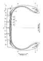
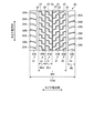
図1は、本発明の実施の形態にかかる空気入りタイヤ1を示すタイヤ子午線方向の断面図である。図1は、空気入りタイヤ1(以下、単にタイヤ1と称することがある)のタイヤ径方向の片側領域の断面図を示している。図2は、空気入りタイヤ1のトレッドパターンを示す展開図である。 FIG. 1 is a cross-sectional view in the tire meridian direction showing the pneumatic tire 1 according to the embodiment of the present invention. FIG. 1 shows a cross-sectional view of a one-sided region in the tire radial direction of a pneumatic tire 1 (hereinafter, may be simply referred to as a tire 1). FIG. 2 is a developed view showing a tread pattern of the pneumatic tire 1.
図1において、タイヤ子午線方向の断面とは、タイヤ回転軸(図示省略)を含む平面でタイヤを切断したときの断面をいう。また、符号CLは、タイヤ赤道面であり、タイヤ回転軸方向にかかるタイヤの中心点を通りタイヤ回転軸に垂直な平面をいう。また、タイヤ幅方向とは、タイヤ回転軸に平行な方向をいい、タイヤ径方向とは、タイヤ回転軸に垂直な方向をいう。 In FIG. 1, the cross section in the tire meridian direction means a cross section when a tire is cut on a plane including a tire rotation axis (not shown). Further, the reference numeral CL is a tire equatorial plane, and refers to a plane that passes through the center point of the tire in the tire rotation axis direction and is perpendicular to the tire rotation axis. Further, the tire width direction means a direction parallel to the tire rotation axis, and the tire radial direction means a direction perpendicular to the tire rotation axis.
図1において、空気入りタイヤ1は、一対のビードコア11、11と、カーカス層13と、ベルト層14と、トレッド部20を構成するトレッドゴム15と、左右のサイドウォール部を構成するサイドウォールゴム16、16と、左右のビード部を構成するリムクッションゴム17、17とを備える。ベルト層14は、複数のベルトプライを積層した構成である。ベルト層14は、図1では、高角度ベルト141、一対の交差ベルトプライ142、143およびベルトカバー144を積層した構成である。ビードコア11のタイヤ径方向外側にビードフィラーが設けられていてもよい。なお、上述したタイヤ内部構造は空気入りタイヤにおける代表的な例を示すものであるが、これに限定されるものではない。
In FIG. 1, the pneumatic tire 1 includes a pair of
[トレッド部]
図2に示すように、トレッド部20は、タイヤ赤道面CLの位置でタイヤ周方向に延在する第一周方向主溝21と、タイヤ赤道面CLの両側において、第一周方向主溝21よりもタイヤ幅方向外側の位置でタイヤ周方向に延びる一対の第二周方向主溝22と、第二周方向主溝22よりもタイヤ幅方向外側の位置でタイヤ周方向に延びる一対の第三周方向主溝23とを備える。
[Tread part]
As shown in FIG. 2, the
第一周方向主溝21、第二周方向主溝22、第三周方向主溝23は、タイヤ周方向に延在する、5本の周方向主溝である。第二周方向主溝22、第三周方向主溝23は、タイヤ赤道面CLを中心として左右対称の位置に配置されることが好ましい。第一周方向主溝21、第二周方向主溝22、第三周方向主溝23は、溝深さが、例えば、13[mm]以上23[mm]以下である。なお、第一周方向主溝21、第二周方向主溝22、第三周方向主溝23は、溝底に、JATMAに規定されるウェアインジケータの表示義務を有する溝である。
The first circumferential
ここで、第一周方向主溝21の溝幅をW1、第二周方向主溝22の溝幅をW2、第三周方向主溝23の溝幅をW3とする。第一周方向主溝21の溝幅W1および第二周方向主溝22の溝幅W2に対し、第三周方向主溝23の溝幅W3は大きい。溝幅は、溝の対向する壁面同士の距離である。
Here, the groove width of the first circumferential direction
溝幅W1および溝幅W2は、例えば、1[mm]以上5[mm]以下である。溝幅W3は、例えば、5[mm]以上15[mm]以下である。なお、第一周方向主溝21の溝幅W1、第二周方向主溝22の溝幅W2、第三周方向主溝23の溝幅W3は、上記範囲に限定されない。
The groove width W1 and the groove width W2 are, for example, 1 [mm] or more and 5 [mm] or less. The groove width W3 is, for example, 5 [mm] or more and 15 [mm] or less. The groove width W1 of the first circumferential
トレッド部20は、第一周方向主溝21、第二周方向主溝22、第三周方向主溝23が形成されることで、複数の陸部に区画される。具体的には、トレッド部20において、第一周方向主溝21と第二周方向主溝22との間の陸部が、タイヤ周方向に延在する第一陸部31となる。第一陸部31は、タイヤ幅方向に延在するラグ溝24によって、複数のブロック31Bに分断される。つまり、第一陸部31は、ラグ溝24によって分断されてタイヤ周方向に並ぶ、複数のブロック31Bによって構成される。
The
トレッド部20において、第二周方向主溝22と第三周方向主溝23との間の陸部が、タイヤ周方向に延在する第二陸部32となる。第二陸部32は、タイヤ幅方向に延在するラグ溝24によって、複数のブロック32Bに分断される。つまり、第二陸部32は、ラグ溝24によって分断されてタイヤ周方向に並ぶ、複数のブロック32Bによって構成される。
In the
ここで、図2に示すように、トレッド部20は、すべてのラグ溝24が、タイヤ幅方向外側の端部よりもタイヤ幅方向内側の端部の方がタイヤ回転方向の一方側に向いている方向性パターンを有する。例えば、図2の上側がタイヤ回転方向の蹴出し側で、図2の下側がタイヤ回転方向の踏込み側である場合、すべてのラグ溝24は、タイヤ幅方向外側の端部よりもタイヤ幅方向内側の端部の方がタイヤ回転方向の踏込み側に向いている。つまり、タイヤ赤道面CLを挟んで両側の陸部31、32において、ラグ溝24の傾斜方向がV字基調になるよう、タイヤ幅方向に対して傾斜している。タイヤ赤道面CLを挟んで両側の陸部31、32において、ラグ溝24の傾斜がV字基調であることにより、トラクション性能が向上する。
Here, as shown in FIG. 2, in the
トレッド部20において、ブロック31Bおよび32Bの配置範囲のタイヤ幅方向の長さWHの、トレッド展開幅TDWに対する比が0.55以上0.70以下の範囲であることが好ましく、0.60以上0.65以下であることがより好ましい。この範囲に幅広のブロックを配置することにより、トレッド部20の剛性を高め、転がり抵抗を低減できる。ここで、トレッド部20において、ブロック31B、32Bのタイヤ幅方向の長さをWa1、Wa2とする。長さWHは、ショルダー部を除く全てのブロック列を含む幅すなわち、WH=W1+2×Wa1+2×W2+2×Wa2である。長さWa1、Wa2の、トレッド展開幅TDWに対する比Wa1/TDW、Wa2/TDWがともに0.15以上0.20以下であることが好ましい。比Wa1/TDW、Wa2/TDWが小さいほどブロックの剛性が小さくなる。比Wa1/TDW、Wa2/TDWが上記の範囲内であれば、転がり抵抗を抑制しつつ、排水性能を向上させることができる。トレッド展開幅TDWは、2つのショルダー陸部である第三陸部33のタイヤ幅方向外側の両端のタイヤ幅方向の距離である。トレッド展開幅TDWとは、タイヤ1を規定リムにリム組みして規定内圧を充填した状態で、荷重を加えないときの、タイヤ1のトレッド部20の展開図における両端の直線距離をいう。
In the
また、トレッド部20において、複数の陸部のうちタイヤ幅方向最外側の陸部に隣接する最外側の第三周方向主溝23以外の第一周方向主溝21、第二周方向主溝22の溝幅の、トレッド展開幅TDWに対する比が0.007以上0.024以下であることが好ましく、0.010以上0.020以下であることがより好ましい。トレッド部20において、最外側の第三周方向主溝23以外の第一周方向主溝21の溝幅W1、第二周方向主溝22の溝幅W2の、最外側の第三周方向主溝23の溝幅W3に対する比W1/W3、比W2/W3がともに0.15以上0.45以下であることが好ましく、0.30以上0.40以下であることがより好ましい。
Further, in the
このように、トレッド部20は、狭い溝幅の第一周方向主溝21および第二周方向主溝22によって第一陸部31および第二陸部32を区画することにより、接地の際に第一周方向主溝21および第二周方向主溝22が閉じ、ブロック31Bおよび32Bが幅広のブロックとして作用する。ブロック31Bおよび32Bによる幅広のブロックにより、転がり抵抗を低減できる。
As described above, the
さらに、トレッド部20において、タイヤ幅方向最外側の第三周方向主溝23の溝幅W3の、トレッド展開幅TDWに対する比が0.025以上0.055以下であることが好ましく、0.030以上0.050以下であることがより好ましい。トレッド部20において、ラグ溝24の溝幅の、トレッド展開幅TDWに対する比が0.003以上0.016以下であることが好ましく、0.007以上0.012以下であることがより好ましい。
Further, in the
タイヤ赤道面CLを挟む両側の陸部31、32は、各片側の陸部31、32すべてにおいて、陸部31、32内のブロック31B、32Bのタイヤ周方向最大長さに対する、タイヤ周方向長さの中点位置同士のタイヤ周方向長さの比が0.90以上1.10以下であることが好ましい。これは、ブロック31B、32Bのタイヤ周方向の位置がほぼ同じであることを意味する。このことについて、図3、図4を参照して説明する。
The
図3は、図2に示すトレッド部20のうち、タイヤ赤道面CLに対して図中左側の陸部31、32の一部を拡大して示す図である。図3を参照すると、タイヤ赤道面CLを挟む左側の陸部31のブロック31Bのタイヤ周方向長さの中点位置をMB1、陸部32のブロック32Bのタイヤ周方向長さの中点位置をMB2とする。中点位置MB1と中点位置MB2とのタイヤ周方向の距離は、タイヤ周方向長さの中点位置同士のタイヤ周方向長さである。陸部31、32内のブロックのタイヤ周方向最大長さLBに対する、タイヤ周方向長さの中点位置同士のタイヤ周方向長さの比は0.90以上1.10以下であることが好ましい。
FIG. 3 is an enlarged view of a part of the
図4は、図2に示すトレッド部20のうち、タイヤ赤道面CLに対して図中右側の陸部31、32の一部を拡大して示す図である。図4を参照すると、タイヤ赤道面CLを挟む右側の陸部31のブロック31Bのタイヤ周方向長さの中点位置をMB1、陸部32のブロック32Bのタイヤ周方向長さの中点位置をMB2とする。中点位置MB1と中点位置MB2とのタイヤ周方向の距離は、タイヤ周方向長さの中点位置同士のタイヤ周方向長さである。陸部31、32内のブロックのタイヤ周方向最大長さLBに対する、タイヤ周方向長さの中点位置同士のタイヤ周方向長さの比は0.90以上1.10以下であることが好ましい。
FIG. 4 is an enlarged view of a part of the
タイヤ赤道面CLを挟んで両側の陸部31は、一方のラグ溝24のタイヤ周方向に占める範囲が他方のブロック31Bのタイヤ周方向に占める範囲に含まれることが好ましい。これは、タイヤ赤道面CLを挟む左右の陸部同士については、タイヤ周方向の位置がずれていることを意味する。このことについて、図5を参照して説明する。
It is preferable that the
図5は、図2に示すトレッド部20のうち、タイヤ赤道面CLを挟む両側の陸部31、31の一部を拡大して示す図である。図5を参照すると、タイヤ赤道面CLに最も近い左右の陸部31、31において、左側の陸部31のラグ溝24がタイヤ周方向に占める範囲C1は、右側の陸部31のブロック31Bがタイヤ周方向に占める範囲D1に含まれていることが好ましい。つまり、範囲D1が範囲C1を完全に含んでいることが好ましい。また、図5において、右側の陸部31のラグ溝24がタイヤ周方向に占める範囲C2は、左側の陸部31のブロック31Bがタイヤ周方向に占める範囲D2に含まれていることが好ましい。つまり、範囲D2が範囲C2を完全に含んでいることが好ましい。図5を参照して説明したように、タイヤ赤道面CLを挟む左右の陸部31、31同士については、タイヤ周方向の位置がずれている。タイヤ周方向の位置がずれていることにより、空気入りタイヤ1が接地する際の騒音を低減することができる。
FIG. 5 is an enlarged view of a part of the
また、図5において、タイヤ赤道面CLを挟んで、タイヤ赤道面CLに最も近い左右両側の陸部31、31は、一方の陸部のラグ溝24のタイヤ周方向に占める範囲C1を想定する。さらに、この範囲C1の端部からのタイヤ周方向の距離C11とC12とが等しい、タイヤ周方向の中心線C0を想定する。また、中心線C0をタイヤ幅方向に延長し、中心線C0から他方の陸部のブロック31Bのタイヤ周方向に占める範囲D1の各端部までの距離D11、D12を想定する。この場合に、距離D11と距離D12との比D11/D12は、
0.65≦D11/D12≦1.65
であることが好ましい。距離D11と距離D12との比の値がこの範囲内であれば、騒音低減効果が大きい。距離D11と距離D12との比D11/D12が1.0に近い値である場合、ラグ溝24の中心線C0がブロック31Bのタイヤ周方向に占める範囲D1の中心に近づく傾向になる。このため、比D11/D12が1.0である場合には、騒音低減効果がより大きい。
Further, in FIG. 5, it is assumed that the
0.65 ≤ D11 / D12 ≤ 1.65
Is preferable. When the value of the ratio of the distance D11 and the distance D12 is within this range, the noise reduction effect is large. When the ratio D11 / D12 between the distance D11 and the distance D12 is close to 1.0, the center line C0 of the
さらに、図5において、ブロック31Bのタイヤ周方向の範囲D1の長さをLD1とし、ラグ溝24のタイヤ周方向の範囲C1の長さをLC1とする。複数の陸部31、31のうちの同じ陸部においては、長さLD1に対する、長さLC1の比LC1/LD1の値は0.2以上0.6以下であることが好ましい。他の陸部32のブロック32Bおよびラグ溝24についても同様である。比LC1/LD1の値がこの範囲の値であれば、トラクション効果と、耐偏摩耗性効果が大きい。なお、範囲C1、範囲C2のタイヤ周方向の長さLC1、LC2は、10.0[mm]以下であることが好ましい。
Further, in FIG. 5, the length of the range D1 in the tire circumferential direction of the
比LC1/LD1=0である場合、ラグ溝24はタイヤ幅方向に対して平行になる。逆に、比LC1/LD1の値が大きくなると、ラグ溝24のタイヤ幅方向に対する角度が大きくなり、V字基調が強くなる。
When the ratio LC1 / LD1 = 0, the
陸部31を構成するブロック31Bの横の長さに対する縦の長さの比すなわちアスペクト比は、1.05以上1.65以下であることが好ましく、1.15以上1.50以下であることがより好ましい。他の陸部32のブロック32Bについても同様である。アスペクト比がこの範囲の値であれば、転がり抵抗抑制効果と、耐偏摩耗性効果が大きい。アスペクト比は、ブロック31Bのタイヤ周方向の範囲D1、D2の長さLD1、LD2の最大値の、ブロック31Bのタイヤ幅方向の長さE1、E2の最大値に対する比である。
The ratio of the vertical length to the horizontal length of the
タイヤ周方向に沿ったタイヤ外周長に対する、ブロック31Bのタイヤ周方向の配列ピッチ長PBの比が0.010以上0.030以下であることが好ましい。タイヤ外周長は、空気入りタイヤ1の直径に円周率πを乗じることによって算出できる。空気入りタイヤ1の直径は、空気入りタイヤ1を規定リムに装着して規定内圧(例えば900kPa)を付与すると共に無負荷状態として測定される。
It is preferable that the ratio of the array pitch length PB of the
ここで、規定リムとは、JATMAに規定される「適用リム」、TRAに規定される「Design Rim」、あるいはETRTOに規定される「Measuring Rim」をいう。また、規定内圧とは、JATMAに規定される「最高空気圧」、TRAに規定される「TIRE LOAD LIMITS AT VARIOUS COLD INFLATION PRESSURES」の最大値、あるいはETRTOに規定される「INFLATION PRESSURES」をいう。また、規定荷重とは、JATMAに規定される「最大負荷能力」、TRAに規定される「TIRE LOAD LIMITS AT VARIOUS COLD INFLATION PRESSURES」の最大値、あるいはETRTOに規定される「LOAD CAPACITY」をいう。ただし、JATMAにおいて、乗用車用タイヤの場合には、規定内圧が空気圧180[kPa]であり、規定荷重が最大負荷能力の88[%]である。 Here, the specified rim means an "applicable rim" specified in JATMA, a "Design Rim" specified in TRA, or a "Measuring Rim" specified in ETRTO. The specified internal pressure means the "maximum air pressure" specified in JATTA, the maximum value of "TIRE LOAD LIMITS AT VARIOUS COLD INFLATION PRESSURES" specified in TRA, or "INFLATION PRESSURES" specified in ETRTO. The specified load means the "maximum load capacity" specified in JATTA, the maximum value of "TIRE LOAD LIMITS AT VARIOUS COLD INFLATION PRESSURES" specified in TRA, or the "LOAD CAPACITY" specified in ETRTO. However, in JATTA, in the case of a passenger car tire, the specified internal pressure is an air pressure of 180 [kPa], and the specified load is 88 [%] of the maximum load capacity.
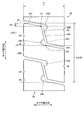
[ラグ溝]
図6は、第一陸部31、第二陸部32を各ブロックに分断するラグ溝24を拡大して示す図である。図6に示すトレッド部20において、本例のラグ溝24は、屈曲点K1、K2を有する。屈曲点K1、K2は、溝の延在方向が変化する点である。図6に示す場合、各ラグ溝24は、2つの屈曲点K1、K2を有している。この場合に限らず、各ラグ溝24は、屈曲点を少なくとも1つ有していればよい。
[Lug groove]
FIG. 6 is an enlarged view showing a
図6において、本例のラグ溝24は、溝241、溝242および溝243から構成されている。本例のラグ溝24は、溝241と溝242との間に屈曲点K1を有し、溝243と溝242との間に屈曲点K2を有する。屈曲点K2は、本例では、溝242の溝壁24Bを延長した仮想線24Cが溝243の溝壁に突き当たる点である。
In FIG. 6, the
溝241はタイヤ幅方向に対して所定角度の方向に延在しており、タイヤ幅方向に対する角度が大きくなるように延在方向が変化した溝242との境界位置が屈曲点K1である。同様に、溝243はタイヤ幅方向に対して所定角度の方向に延在しており、タイヤ幅方向に対する角度が大きくなるように延在方向が変化した溝242との境界位置が屈曲点K2である。
The
トレッド部20は、屈曲点K1の近傍で、溝241の端部に、丸部24Dを有する。トレッド部20は、屈曲点K2の近傍で、溝243の端部に、丸部24Eを有する。丸部24Dおよび丸部24Eにより、ラグ溝24が屈曲することによって生じやすいクラックの発生を防止することができる。
The
ここで、ブロック32Bのタイヤ周方向端部から屈曲点K1、K2までのタイヤ周方向に沿った長さを、LK1、LK2とする。ブロック32Bのタイヤ周方向長さLに対する、長さLK1、LK2の比LK1/L、LK2/Lは、ともに0.1以上0.4以下であることが好ましい。比LK1/L、LK2/Lの値がこれらの範囲であれば、屈曲点K1、K2が適切な位置になり、ブロック同士の支え合いによってトレッド部20の剛性が上昇し、転がり抵抗を低減しつつ、トラクション効果が得られる。なお、ラグ溝24は、溝深さDLが5.0mm以上20.0mm以下であることが好ましい。
Here, the lengths of the
[切欠部]
図6において、トレッド部20は、第二陸部32のブロック32Bの周方向主溝側の少なくとも一辺に設けられた切欠部26をさらに備える。第一陸部31のブロック31Bについても同様である。切欠部26は、ブロック32Bの端部の耐偏摩耗性を向上する機能を有する。切欠部26は、マルチサイプと同様の効果を実現するものである。転がり抵抗を低減しうるトレッドゴム15を使用する場合において、サイプを設けると、サイプにクラックが発生する可能性が少なくない。このため、本例のトレッド部20は、サイプの代替として、切欠部26を有する。
[Notch]
In FIG. 6, the
図7は、切欠部26の付近を拡大して示す図である。図6および図7において、ブロック32Bのタイヤ周方向の最大長さLBに対する切欠部26のタイヤ周方向の最大長さL26の比が0.015以上0.070以下であることが好ましく、0.030以上0.055以下であることがより好ましい。さらに、ブロック32Bのタイヤ幅方向の最大長さEに対する切欠部26のタイヤ幅方向の最大長さW26の比が0.007以上0.035以下であることが好ましく、0.015以上0.028以下であることがより好ましい。
FIG. 7 is an enlarged view showing the vicinity of the
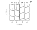
[ショルダー部]
図2に戻り、トレッド部20において、最外側周方向主溝である第三周方向主溝23のタイヤ幅方向外側の陸部が第三陸部33となる。第三陸部33は、トレッド部20のうち、ショルダー部に位置している、ショルダー陸部である。第三陸部33は、タイヤ幅方向に延在する第1ショルダーラグ溝25Aと第2ショルダーラグ溝25Bとによって、複数のブロック33Bに分断される。このため、第三陸部33は、分断された複数のブロック33Bがタイヤ周方向に並ぶ構成になっている。
[Shoulder part]
Returning to FIG. 2, in the
ショルダー陸部である第三陸部33のタイヤ幅方向長さに対する、第三陸部33以外の陸部のタイヤ幅方向長さの比が0.70以上1.00以下であることが好ましい。第三陸部33以外の陸部である第一陸部31のタイヤ幅方向長さをWa1、第三陸部33以外の陸部である第二陸部32のタイヤ幅方向長さをWa2とすると、第三陸部33のタイヤ幅方向長さWbに対する、第三陸部33以外の陸部のタイヤ幅方向長さの比Wa1/Wb、Wa2/Wbがともに0.70以上1.00以下であることが好ましい。
It is preferable that the ratio of the length in the tire width direction of the
ここで、トレッド部20の接地面のタイヤ周方向長さをTL(図示省略)とする。トレッド部20の接地面のタイヤ周方向長さTLに対する、ショルダー陸部である第三陸部33のタイヤ幅方向長さWbの比Wb/TLが0.20以下であることが好ましい。トレッド部20の接地面のタイヤ周方向長さTLは、空気入りタイヤ1を規定リムに装着して規定内圧を付与すると共に無負荷状態として測定される。
Here, the length of the ground contact surface of the
[ショルダーラグ溝]
トレッド部20は、ショルダー陸部である第三陸部33を横断するショルダーラグ溝25A、25Bを備える。第1ショルダーラグ溝25Aと第2ショルダーラグ溝25Bとは、互いに溝幅が異なる。第1ショルダーラグ溝25Aと第2ショルダーラグ溝25Bとは、タイヤ周方向に交互に、第三陸部33に配置される。
[Shoulder lug groove]
The
ここで、第一周方向主溝21、第二周方向主溝22、第三周方向主溝23の溝深さをGDとする。第1ショルダーラグ溝25Aおよび第2ショルダーラグ溝25Bの溝深さをDLoとする。溝深さGDに対する、溝深さDLoの比DLo/GDは、0.03以上0.5以下であることが好ましい。第1ショルダーラグ溝25Aおよび第2ショルダーラグ溝25Bは、溝幅Woが0.5[mm]以上5.0[mm]以下であることが好ましい。
Here, the groove depths of the first circumferential
図1に戻り、空気入りタイヤ1は、タイヤ赤道面CLに平行な線CL1とショルダー陸部すなわち複数の陸部のうちタイヤ幅方向最外側である第三陸部33のタイヤ幅方向外側の側面とのなす角αが5[deg]以上20[deg]以下である。
Returning to FIG. 1, the pneumatic tire 1 has a line CL1 parallel to the tire equatorial plane CL and a side surface of the shoulder land portion, that is, the outermost side surface of the
[トレッド部の他の構成例]
上述したように、タイヤ赤道面CLを挟んで両側の陸部31、32において、ラグ溝24の傾斜方向がV字基調であることにより、トラクション性能が向上する。トラクション性能の向上のためには、トレッド部20において、ラグ溝24は屈曲点を備えていなくてもよい。図8はトレッド部の他の構成例を示す図である。図8に示すように、トレッド部20Aは、ラグ溝24Aを備えている。ラグ溝24Aは、屈曲点を備えていない。図8に示すトレッド部20Aのすべてのラグ溝24Aは、タイヤ幅方向外側の端部よりもタイヤ幅方向内側の端部の方がタイヤ回転方向の一方側に向いている。このため、図2の場合と同様に、タイヤ赤道面CLを挟んで両側の第一陸部31、第二陸部32において、ラグ溝24Aの傾斜方向がV字基調になるよう、タイヤ幅方向に対して傾斜している。タイヤ赤道面CLを挟んで両側の陸部31、32において、ラグ溝24Aの傾斜方向がV字基調であることにより、トラクション性能が向上する。図8に示すトレッド部20Aによれば、タイヤ赤道面CLを挟んだ片側において、第一陸部31、第二陸部32を構成する各ブロックのうち、タイヤ幅方向に隣り合うブロックは、タイヤ周方向において同じ位置に配置してあるため、接地時に掛かる負荷を均一化でき、ヒール・アンド・トウ偏摩耗を改善できる。
[Other configuration examples of the tread portion]
As described above, the traction performance is improved by the inclination direction of the
また、ラグ溝24が屈曲することによって、トレッド部20の剛性が上昇し、転がり抵抗を低減できる。トレッド部20の剛性を上昇させ、転がり抵抗を低減するためには、トレッド部20において、ラグ溝24の傾斜方向がV字基調でなくてもよい。図9はトレッド部の他の構成例を示す図である。図9に示すように、トレッド部20Bは、屈曲点を有するラグ溝24を備えている。ただし、図2および図8の場合とは異なり、タイヤ赤道面CLを挟んで両側の第一陸部31、第二陸部32において、ラグ溝24の傾斜方向はV字基調になっていない。しかしながら、ラグ溝24において、屈曲点K1、K2が適切な位置であれば、ブロック同士の支え合いによってトレッド部20Bの剛性が上昇し、転がり抵抗を低減しつつ、トラクション効果が得られる。図9に示すトレッド部20Bによれば、タイヤ赤道面CLを挟んだ片側において、第一陸部31、第二陸部32を構成する各ブロックのうち、タイヤ幅方向に隣り合うブロックは、タイヤ周方向において同じ位置に配置してあるため、接地時に掛かる負荷を均一化でき、ヒール・アンド・トウ偏摩耗を改善できる。
Further, by bending the
ところで、転がり抵抗を低減するには、狭い溝幅の第一周方向主溝21および第二周方向主溝22によって第一陸部31および第二陸部32を区画し、接地の際に第一周方向主溝21および第二周方向主溝22が閉じ、ブロック31Bおよび32Bが幅広のブロックとして作用すればよい。この作用を実現するには、ラグ溝24が屈曲しておらず、ラグ溝24の傾斜方向がV字基調でなくてもよい。図10はトレッド部の他の構成例を示す図である。図10に示すように、トレッド部20Cにおいて、ラグ溝24Aは屈曲していない。また、ラグ溝24Aの傾斜方向はV字基調ではない。図10に示す場合でも、接地の際に第一周方向主溝21および第二周方向主溝22が閉じ、ブロック31Bおよび32Bが幅広のブロックとして作用し、転がり抵抗を低減できる。図10に示すトレッド部20Cによれば、タイヤ赤道面CLを挟んだ片側において、第一陸部31、第二陸部32を構成する各ブロックのうち、タイヤ幅方向に隣り合うブロックは、タイヤ周方向において同じ位置に配置してあるため、接地時に掛かる負荷を均一化でき、ヒール・アンド・トウ偏摩耗を改善できる。
By the way, in order to reduce the rolling resistance, the
[まとめ]
本例の空気入りタイヤ1によれば、接地時に溝が閉じて幅広のリブブロックとなることにより、耐転がり抵抗性能を改善できる。また、本例の空気入りタイヤ1によれば、方向性パターンとし、V字基調のラグ溝を設けることにより、トラクション性を向上できる。さらに、本例の空気入りタイヤ1によれば、ブロックを同じ位置に配置して接地時に掛かる負荷を均一化することにより、ヒール・アンド・トウ偏摩耗を改善できる。また、本例の空気入りタイヤ1によれば、ラグ溝が連通しないことにより、通過騒音を低減できる。
[summary]
According to the pneumatic tire 1 of this example, the rolling resistance performance can be improved by closing the groove and forming a wide rib block at the time of touchdown. Further, according to the pneumatic tire 1 of this example, the traction property can be improved by forming a directional pattern and providing a V-shaped lug groove. Further, according to the pneumatic tire 1 of this example, the heel-and-toe uneven wear can be improved by arranging the blocks at the same position and equalizing the load applied at the time of touchdown. Further, according to the pneumatic tire 1 of this example, the passing noise can be reduced because the lug grooves do not communicate with each other.
[実施例]
表1から表5は、本発明の実施の形態にかかる空気入りタイヤの性能試験の結果を示す表である。この性能試験では、複数種類の試験タイヤについて、耐転がり抵抗性能、トラクション性能、通過騒音(PBN;Pass-by Noise)性能、耐偏摩耗性能に関する評価が行われた。評価に用いられた空気入りタイヤ1のサイズは、315/70R22.5である。評価に用いた車両は、6×4トラクターにトレーラーを接続した車両である。
[Example]
Tables 1 to 5 are tables showing the results of performance tests of pneumatic tires according to the embodiment of the present invention. In this performance test, rolling resistance performance, traction performance, pass-by noise (PBN) performance, and uneven wear resistance performance were evaluated for a plurality of types of test tires. The size of the pneumatic tire 1 used for the evaluation is 315 / 70R22.5. The vehicle used for the evaluation is a vehicle in which a trailer is connected to a 6 × 4 tractor.
耐転がり抵抗性能の評価には、室内ドラム試験機が用いられた。耐転がり抵抗性能の評価では、上記試験タイヤに正規内圧を充填し、荷重4kNおよび速度50km/h時における抵抗力を測定した。この測定結果に基づいて比較例1を基準(100)とした指数評価が行われた。この評価は、指数が大きいほど転がり抵抗が小さく、耐転がり抵抗性能が優れていることを示している。 An indoor drum tester was used to evaluate the rolling resistance performance. In the evaluation of rolling resistance performance, the test tire was filled with a normal internal pressure, and the resistance was measured at a load of 4 kN and a speed of 50 km / h. Based on this measurement result, an index evaluation was performed using Comparative Example 1 as a reference (100). This evaluation shows that the larger the index, the smaller the rolling resistance, and the better the rolling resistance performance.
トラクション性能に関する評価は、ウェットグリップ性能を測定することによって行った。ウェットグリップ性能の測定は、水深5mmのアスファルト路面で制動試験を行い、その制動距離を基に、比較例1を100として指数によって評価した。この数値が大きいほどトラクション性能が良好であることを示している。 The evaluation of traction performance was performed by measuring the wet grip performance. The wet grip performance was measured by performing a braking test on an asphalt road surface having a water depth of 5 mm, and based on the braking distance, comparative example 1 was set as 100 and evaluated by an index. The larger this value is, the better the traction performance is.
通過騒音性能に関する評価では、ECE R117−02(ECE Regulation No.117Revision 2)に定めるタイヤ騒音試験法に従って測定した車外通過音の大きさによって評価した。この試験では、試験車両を騒音測定区間の十分前から走行させ、当該区間の手前でエンジンを停止し、惰行走行させた時の騒音測定区間における最大騒音値dB(周波数800Hz〜1200Hzの範囲の騒音値)を、基準速度に対し±10km/hの速度範囲をほぼ等間隔に8以上に区切った複数の速度で測定し、平均を車外通過騒音とした。最大騒音値dBは、騒音測定区間内の中間点において走行中心線から側方に7.5m、且つ路面から1.2mの高さに設置した定置マイクロフォンを用いてA特性周波数補正回路を通して測定した音圧dB(A)である。通過騒音は、この測定結果を、比較例1を基準(0dB)とし、その数値が小さいほど音圧dBが小さく、通過騒音に対するノイズ性能が優れていることを示している。 In the evaluation of the passing noise performance, the loudness of the passing noise measured according to the tire noise test method specified in ECE R117-02 (ECE Regulation No. 117Revision 2) was used for evaluation. In this test, the maximum noise value dB (noise in the frequency range of 800 Hz to 1200 Hz) in the noise measurement section when the test vehicle is run from sufficiently in front of the noise measurement section, the engine is stopped before the section, and the test vehicle is coasted. The value) was measured at a plurality of speeds in which a speed range of ± 10 km / h with respect to the reference speed was divided into 8 or more at approximately equal intervals, and the average was taken as the noise passing outside the vehicle. The maximum noise value dB was measured through the A-weighting frequency correction circuit using a stationary microphone installed at a height of 7.5 m from the traveling center line to the side and 1.2 m from the road surface at the midpoint in the noise measurement section. The sound pressure is dB (A). As for the passing noise, the measurement result is used as a reference (0 dB) based on Comparative Example 1, and the smaller the value, the smaller the sound pressure dB, and the better the noise performance with respect to the passing noise.
耐偏摩耗性能については、上記車両の6×4トラクターの駆動軸に、空気入りタイヤ1を装着したリムを装着し、4万km走行後のヒール・アンド・トウ摩耗量を測定した。測定結果は指数化した。空気入りタイヤ1を装着したリムは、22.5×9.00であり、空気圧を900kPaとした。 Regarding the uneven wear resistance performance, a rim equipped with the pneumatic tire 1 was attached to the drive shaft of the 6 × 4 tractor of the vehicle, and the heel-and-toe wear amount after traveling 40,000 km was measured. The measurement results were indexed. The rim equipped with the pneumatic tire 1 was 22.5 × 9.00, and the air pressure was 900 kPa.
また、比較対象として、比較例1、比較例2および比較例3のタイヤを用意して上記と同様に、耐転がり抵抗性能、トラクション性能、通過騒音性能、耐偏摩耗性能に関する評価が行われた。比較例1のタイヤは、タイヤ周方向に延在する4本の周方向主溝と、周方向主溝によって区画された複数の陸部とを備えており、複数の陸部は、ラグ溝によって分断されてタイヤ周方向に並ぶブロックで構成され、ブロックのタイヤ幅方向の範囲の、トレッド展開幅に対する比が0.63、複数の陸部のうちタイヤ幅方向最外側の陸部に隣接する最外側周方向主溝以外の周方向主溝の溝幅の、トレッド展開幅に対する比が0.030、かつ、最外側周方向主溝の溝幅に対する比が0.50、最外側周方向主溝の溝幅の、トレッド展開幅に対する比が0.040、ラグ溝の溝幅の、トレッド展開幅に対する比が0.020、タイヤ赤道面を挟む両側の陸部は、各片側の陸部すべてにおいて、陸部内のブロックのタイヤ周方向最大長さに対する、タイヤ周方向長さの中点位置同士のタイヤ周方向長さの比が1.20、タイヤ赤道面を挟んで両側の陸部は、一方のラグ溝のタイヤ周方向に占める範囲が他方のブロックのタイヤ周方向に占める範囲に含まれるタイヤである。比較例1のタイヤは、ラグ溝が、タイヤ幅方向外側の端部よりもタイヤ幅方向内側の端部の方がタイヤ回転方向の一方側に向いている方向性パターンではなく、ラグ溝の傾斜がV字基調ではない。 Further, the tires of Comparative Example 1, Comparative Example 2 and Comparative Example 3 were prepared as comparison targets, and the rolling resistance performance, the traction performance, the passing noise performance, and the uneven wear resistance were evaluated in the same manner as described above. .. The tire of Comparative Example 1 includes four circumferential main grooves extending in the tire circumferential direction and a plurality of land portions partitioned by the circumferential main grooves, and the plurality of land portions are formed by lug grooves. It is composed of blocks that are divided and lined up in the tire circumferential direction, and the ratio of the block in the tire width direction to the tread deployment width is 0.63. The ratio of the groove width of the circumferential main groove other than the outer peripheral main groove to the tread expansion width is 0.030, and the ratio to the groove width of the outermost peripheral main groove is 0.50, the outermost peripheral main groove. The ratio of the groove width to the tread unfolded width is 0.040, the ratio of the lug groove groove width to the tread unfolded width is 0.020, and the land parts on both sides of the tire equatorial plane are in all the land parts on one side. , The ratio of the tire circumferential length between the midpoint positions of the tire circumferential length to the maximum tire circumferential length of the block in the land is 1.20, and the land on both sides of the tire equatorial plane is on one side. It is a tire included in the range occupied in the tire circumferential direction of the lug groove of the other block in the tire circumferential direction of the other block. In the tire of Comparative Example 1, the lug groove is not a directional pattern in which the inner end in the tire width direction is directed to one side in the tire rotation direction than the outer end in the tire width direction, but the inclination of the lug groove. Is not a V-shaped tone.
比較例2のタイヤは、タイヤ周方向に延在する5本の周方向主溝と、周方向主溝によって区画された複数の陸部とを備えており、複数の陸部は、ラグ溝によって分断されてタイヤ周方向に並ぶブロックで構成され、ブロックのタイヤ幅方向の範囲の、トレッド展開幅に対する比が0.63、複数の陸部のうちタイヤ幅方向最外側の陸部に隣接する最外側周方向主溝以外の周方向主溝の溝幅の、トレッド展開幅に対する比が0.015、かつ、最外側周方向主溝の溝幅に対する比が0.35、最外側周方向主溝の溝幅の、トレッド展開幅に対する比が0.040、ラグ溝の溝幅の、トレッド展開幅に対する比が0.010、タイヤ赤道面を挟む両側の陸部は、各片側の陸部すべてにおいて、陸部内のブロックのタイヤ周方向最大長さに対する、タイヤ周方向長さの中点位置同士のタイヤ周方向長さの比が1.20、タイヤ赤道面を挟んで両側の陸部は、一方のラグ溝のタイヤ周方向に占める範囲が他方のブロックのタイヤ周方向に占める範囲に含まれないタイヤである。比較例2のタイヤは、ラグ溝が、タイヤ幅方向外側の端部よりもタイヤ幅方向内側の端部の方がタイヤ回転方向の一方側に向いている方向性パターンであり、ラグ溝の傾斜がV字基調である。 The tire of Comparative Example 2 includes five circumferential main grooves extending in the tire circumferential direction and a plurality of land portions partitioned by the circumferential main grooves, and the plurality of land portions are formed by lug grooves. It is composed of blocks that are divided and lined up in the tire circumferential direction, and the ratio of the block in the tire width direction to the tread deployment width is 0.63. The ratio of the groove width of the circumferential main groove other than the outer peripheral main groove to the tread expansion width is 0.015, and the ratio to the groove width of the outermost peripheral main groove is 0.35, the outermost peripheral main groove. The ratio of the groove width to the tread unfolded width is 0.040, the ratio of the lug groove groove width to the tread unfolded width is 0.010, and the land parts on both sides of the tire equatorial plane are in all the land parts on one side. , The ratio of the tire circumferential length between the midpoint positions of the tire circumferential length to the maximum tire circumferential length of the block in the land is 1.20, and the land on both sides of the tire equatorial plane is on one side. This is a tire whose range occupied by the tire circumferential direction of the lug groove is not included in the range occupied by the tire circumferential direction of the other block. The tire of Comparative Example 2 has a directional pattern in which the lug groove is oriented toward one side in the tire rotation direction at the inner end in the tire width direction rather than the outer end in the tire width direction, and the lug groove is inclined. Is a V-shaped keynote.
比較例3のタイヤは、タイヤ周方向に延在する5本の周方向主溝と、周方向主溝によって区画された複数の陸部とを備えており、複数の陸部は、ラグ溝によって分断されてタイヤ周方向に並ぶブロックで構成され、ブロックのタイヤ幅方向の範囲の、トレッド展開幅に対する比が0.50、複数の陸部のうちタイヤ幅方向最外側の陸部に隣接する最外側周方向主溝以外の周方向主溝の溝幅の、トレッド展開幅に対する比が0.015、かつ、最外側周方向主溝の溝幅に対する比が0.35、最外側周方向主溝の溝幅の、トレッド展開幅に対する比が0.040、ラグ溝の溝幅の、トレッド展開幅に対する比が0.010、タイヤ赤道面を挟む両側の陸部は、各片側の陸部すべてにおいて、陸部内のブロックのタイヤ周方向最大長さに対する、タイヤ周方向長さの中点位置同士のタイヤ周方向長さの比が1.20、タイヤ赤道面を挟んで両側の陸部は、一方のラグ溝のタイヤ周方向に占める範囲が他方のブロックのタイヤ周方向に占める範囲に含まれるタイヤである。比較例3のタイヤは、ラグ溝が、タイヤ幅方向外側の端部よりもタイヤ幅方向内側の端部の方がタイヤ回転方向の一方側に向いている方向性パターンであり、ラグ溝の傾斜はV字基調ではない。 The tire of Comparative Example 3 includes five circumferential main grooves extending in the tire circumferential direction and a plurality of land portions partitioned by the circumferential main grooves, and the plurality of land portions are formed by lug grooves. It is composed of blocks that are divided and lined up in the tire circumferential direction, and the ratio of the block in the tire width direction to the tread deployment width is 0.50. The ratio of the groove width of the circumferential main groove other than the outer peripheral main groove to the tread expansion width is 0.015, and the ratio to the groove width of the outermost peripheral main groove is 0.35, the outermost peripheral main groove. The ratio of the groove width to the tread unfolded width is 0.040, the ratio of the lug groove groove width to the tread unfolded width is 0.010, and the land parts on both sides of the tire equatorial plane are in all the land parts on one side. , The ratio of the tire circumferential length between the midpoint positions of the tire circumferential length to the maximum tire circumferential length of the block in the land is 1.20, and the land on both sides of the tire equatorial plane is on one side. It is a tire included in the range occupied in the tire circumferential direction of the lug groove of the other block in the tire circumferential direction of the other block. The tire of Comparative Example 3 has a directional pattern in which the lug groove is oriented toward one side in the tire rotation direction at the inner end in the tire width direction rather than the outer end in the tire width direction, and the lug groove is inclined. Is not a V-shaped tone.
表1から表5に示すように、実施例1から実施例51の空気入りタイヤは、タイヤ周方向に延在する5本の周方向主溝(第一周方向主溝21、第二周方向主溝22、第三周方向主溝23)と、周方向主溝によって区画された複数の陸部(第一陸部31、第二陸部32、第三陸部33)とを備え、複数の陸部がラグ溝によって分断されてタイヤ周方向に並ぶブロックで構成されている。
As shown in Tables 1 to 5, the pneumatic tires of Examples 1 to 51 have five circumferential main grooves extending in the tire circumferential direction (first circumferential
また、実施例1から実施例51の空気入りタイヤは、ブロックのタイヤ幅方向の範囲の、トレッド展開幅に対する比(ブロック列設置範囲)が0.55以上0.70以下の範囲であり、複数の陸部のうちタイヤ幅方向最外側の陸部に隣接する最外側周方向主溝以外の周方向主溝の溝幅の、トレッド展開幅に対する比(周方向細主溝幅/トレッド展開幅)が0.007以上0.024以下であり、かつ、最外側周方向主溝の溝幅に対する比(周方向細主溝幅/最外側周方向主溝幅)が0.15以上0.45以下であり、最外側周方向主溝の溝幅の、トレッド展開幅に対する比(最外側周方向主溝幅/トレッド展開幅)が0.025以上0.055以下であり、ラグ溝の溝幅の、トレッド展開幅に対する比(ラグ溝幅/トレッド展開幅)が0.003以上0.016以下であり、タイヤ赤道面を挟む両側の陸部は、各片側の陸部すべてにおいて、陸部内のブロックのタイヤ周方向最大長さに対する、タイヤ周方向長さの中点位置同士のタイヤ周方向長さの比(ブロックの位置)が0.90以上1.10以下であり、タイヤ赤道面を挟んで両側の陸部は、一方のラグ溝のタイヤ周方向に占める範囲が他方のブロックのタイヤ周方向に占める範囲に含まれる(範囲Dが範囲Cを含む)。 Further, the pneumatic tires of Examples 1 to 51 have a range in which the ratio (block row installation range) of the range in the tire width direction of the block to the tread deployment width is 0.55 or more and 0.70 or less, and there are a plurality of them. Ratio of the groove width of the circumferential main groove other than the outermost circumferential main groove adjacent to the outermost land portion in the tire width direction to the tread expansion width (circumferential narrow main groove width / tread expansion width) There is 0.007 or more 0.024 or less, and the ratio of the groove width of the outermost circumferential main groove (circumferential direction Hosonushi groove width / outermost circumferential main groove width) 0.15 0.45 The ratio of the groove width of the outermost circumferential main groove to the tread unfolded width (outermost circumferential main groove width / tread unfolded width) is 0.025 or more and 0.055 or less, and the groove width of the lug groove , The ratio to the tread deployment width (lug groove width / tread deployment width) is 0.003 or more and 0.016 or less, and the land parts on both sides of the tire equatorial plane are blocks in the land part in all the land parts on each side. for the tire circumferential direction maximum length, the ratio of the tire circumferential length of the middle point between the tire circumferential direction length (position of the block) is 0.90 to 1.10, across the tire equatorial plane The land portions on both sides are included in the range occupied by the tire circumferential direction of one lug groove in the tire circumferential direction of the other block (range D includes range C).
実施例23から実施例51の空気入りタイヤは、すべてのラグ溝が、タイヤ幅方向外側の端部よりもタイヤ幅方向内側の端部の方がタイヤ回転方向の一方側に向いている方向性パターンを有し、ラグ溝の傾斜がV字基調である。 In the pneumatic tires of Examples 23 to 51, all the lug grooves are oriented so that the inner end in the tire width direction faces one side in the tire rotation direction than the outer end in the tire width direction. It has a pattern and the inclination of the lug groove is V-shaped.
実施例24から実施例51の空気入りタイヤは、タイヤ赤道面を挟んで両側の陸部において、一方の陸部のラグ溝のタイヤ周方向に占める範囲のタイヤ周方向の中心線から他方の陸部のブロックのタイヤ周方向に占める範囲の各端部までの距離をD11、D12とした場合に、ブロック列ずれD11/D12が0.65≦D11/D12≦1.65である。 The pneumatic tires of Examples 24 to 51 are located on both sides of the tire equatorial plane from the center line of the tire circumferential direction in the range occupied by the lug groove of one land portion in the tire circumferential direction to the other land. When the distances to each end of the block in the tire circumferential direction are D11 and D12, the block row deviation D11 / D12 is 0.65 ≦ D11 / D12 ≦ 1.65.
実施例26から実施例51の空気入りタイヤは、複数の陸部のうちの同じ陸部において、ブロックのタイヤ周方向の長さに対する、ラグ溝のタイヤ周方向の長さの比(ラグ溝の配置範囲C1/E1)が0.2以上0.6以下である。 In the pneumatic tires of Examples 26 to 51, the ratio of the length of the lug groove in the tire circumferential direction to the length of the block in the tire circumferential direction (of the lug groove) in the same land portion among the plurality of land portions. The arrangement range C1 / E1) is 0.2 or more and 0.6 or less.
実施例28から実施例51の空気入りタイヤは、陸部を構成するブロックの縦横比が、1.05以上1.65以下である。 The pneumatic tires of Examples 28 to 51 have an aspect ratio of blocks constituting the land portion of 1.05 or more and 1.65 or less.
実施例32から実施例51の空気入りタイヤは、ラグ溝が屈曲点を少なくとも1つ有し、ブロックのタイヤ周方向長さに対する、ブロックのタイヤ周方向端部から屈曲点までのタイヤ周方向に沿った長さの比(屈曲点の位置)が0.1以上0.4以下である。 In the pneumatic tires of Examples 32 to 51, the lug groove has at least one bending point, and the tire circumferential direction from the tire circumferential end of the block to the bending point with respect to the tire circumferential length of the block. The ratio of lengths along (the position of the bending point) is 0.1 or more and 0.4 or less.
実施例34から実施例51の空気入りタイヤは、ブロックの周方向主溝側の少なくとも一辺に設けられた切欠部をさらに備え、ブロックのタイヤ周方向の最大長に対する、切欠部のタイヤ周方向の最大長の比(切欠部のタイヤ周方向最大長/ブロックのタイヤ周方向最大長)が0.015以上0.070以下であり、かつ、ブロックのタイヤ幅方向の最大長に対する、切欠部のタイヤ幅方向の最大長の比(切欠部のタイヤ幅方向最大長/ブロックのタイヤ周方向最大長)が0.007以上0.035以下である。 The pneumatic tires of Examples 34 to 51 further include a notch provided on at least one side of the block in the circumferential main groove side, in the tire circumferential direction of the notch with respect to the maximum length of the block in the tire circumferential direction. The ratio of the maximum length (maximum tire circumferential length of the notch / maximum tire circumferential length of the block) is 0.015 or more and 0.070 or less, and the tire of the notch is relative to the maximum length of the block in the tire width direction. The ratio of the maximum length in the width direction (the maximum length in the tire width direction of the notch / the maximum length in the tire circumferential direction of the block) is 0.007 or more and 0.035 or less.
実施例42から実施例51の空気入りタイヤは、トレッド展開幅に対する、ブロックのタイヤ幅方向の長さの比(ブロックのタイヤ幅方向長/トレッド展開幅)が0.15以上0.2以下である。 In the pneumatic tires of Examples 42 to 51, the ratio of the length of the block in the tire width direction to the tread deployment width (block tire width direction length / tread deployment width) is 0.15 or more and 0.2 or less. be.
実施例44から実施例51の空気入りタイヤは、タイヤ周方向に沿ったタイヤ外周長に対する、ブロックのタイヤ周方向の配列ピッチ長の比(ブロックの配列ピッチ長/タイヤ外周長)が0.010以上0.030以下である。 In the pneumatic tires of Examples 44 to 51, the ratio of the arrangement pitch length of the block in the tire circumferential direction (the arrangement pitch length of the block / the tire outer circumference length) to the tire outer circumference length along the tire circumferential direction is 0.010. It is 0.030 or less.
実施例46から実施例51の空気入りタイヤは、最外側周方向主溝のタイヤ幅方向外側に設けられたショルダー陸部をさらに備え、ショルダー陸部のタイヤ幅方向長さに対する、ショルダー陸部以外の陸部のタイヤ幅方向長さの比(他の陸部幅/ショルダー陸部幅)が0.70以上1.00以下である。 The pneumatic tires of Examples 46 to 51 further include a shoulder land portion provided on the outer side in the tire width direction of the outermost circumferential main groove, other than the shoulder land portion with respect to the tire width direction length of the shoulder land portion. The ratio of the lengths in the tire width direction of the land portion (other land portion width / shoulder land portion width ) is 0.70 or more and 1.00 or less.
実施例48から実施例51の空気入りタイヤは、トレッド部の接地面のタイヤ周方向長さに対する、ショルダー陸部のタイヤ幅方向長さの比(ショルダー陸部幅/トレッド接地長)が0.20以下である。 In the pneumatic tires of Examples 48 to 51, the ratio of the length in the tire width direction of the shoulder land portion to the tire circumferential length of the ground contact surface of the tread portion (shoulder land portion width / tread ground contact length) is 0. It is 20 or less.
実施例49から実施例51の空気入りタイヤは、ショルダー陸部において、タイヤ幅方向に延在するショルダーラグ溝をさらに備え、周方向主溝の溝深さに対する、ショルダーラグ溝の溝深さの比(ショルダーラグ溝深さ/周方向主溝深さ)が0.03以上0.5以下である。 The pneumatic tires of Examples 49 to 51 further include a shoulder lug groove extending in the tire width direction in the shoulder land portion, and the groove depth of the shoulder lug groove with respect to the groove depth of the circumferential main groove. The ratio (shoulder lug groove depth / circumferential main groove depth) is 0.03 or more and 0.5 or less.
実施例1から実施例51によると、方向性パターンを有し、ラグ溝の傾斜がV字基調である場合、ブロック列ずれD11/D12が0.65≦D11/D12≦1.65である場合、ラグ溝の配置範囲C1/D1が0.2以上0.6以下である場合、陸部を構成するブロックの縦横比が、1.05以上1.65以下である場合、ブロックのタイヤ周方向長さに対する、ブロックのタイヤ周方向端部から屈曲点までのタイヤ周方向に沿った長さの比が0.1以上0.4以下である場合、切欠部のタイヤ周方向最大長/ブロックのタイヤ周方向最大長が0.015以上0.070以下であり、かつ、切欠部のタイヤ幅方向最大長/ブロックのタイヤ周方向最大長が0.007以上0.035以下である場合、ブロックのタイヤ幅方向長/トレッド展開幅が0.15以上0.2以下である場合、ブロックの配列ピッチ長/タイヤ外周長が0.010以上0.030以下である場合、他の陸部幅/ショルダー陸部幅が0.70以上1.00以下である場合、ショルダー陸部幅/トレッド接地長が0.20以下である場合、ショルダーラグ溝深さ/周方向主溝深さが0.03以上0.5以下である場合、に良好な結果が得られることがわかる。 According to Examples 1 to 51, when the tire has a directional pattern and the inclination of the lug groove is V-shaped, the block row deviation D11 / D12 is 0.65 ≦ D11 / D12 ≦ 1.65. , When the arrangement range C1 / D1 of the lug groove is 0.2 or more and 0.6 or less, and when the aspect ratio of the block constituting the land portion is 1.05 or more and 1.65 or less, the tire circumferential direction of the block. When the ratio of the length of the block along the tire circumference from the end of the block to the bending point along the tire circumference is 0.1 or more and 0.4 or less, the maximum tire circumference of the notch / block When the maximum tire circumferential length is 0.015 or more and 0.070 or less, and the maximum tire width direction of the notch / the maximum tire circumferential length of the block is 0.007 or more and 0.035 or less, the block When the tire width direction length / tread deployment width is 0.15 or more and 0.2 or less, when the block arrangement pitch length / tire outer circumference length is 0.010 or more and 0.030 or less, other land width / shoulder When the land width is 0.70 or more and 1.00 or less, when the shoulder land width / tread contact length is 0.20 or less, the shoulder lug groove depth / circumferential main groove depth is 0.03 or more. When it is 0.5 or less, it can be seen that good results are obtained.

1 空気入りタイヤ
11 ビードコア
13 カーカス層
14 ベルト層
15 トレッドゴム
16 サイドウォールゴム
17 リムクッションゴム
20、20A、20B、20C トレッド部
21 第一周方向主溝
22 第二周方向主溝
23 第三周方向主溝
24、24A ラグ溝
24D、24E 丸部
25A、25B ショルダーラグ溝
26 切欠部
31 第一陸部
31B、32B、33B ブロック
32 第二陸部
33 第三陸部
141 高角度ベルト
142、143 交差ベルトプライ
144 ベルトカバー
CL タイヤ赤道面
K1、K2 屈曲点
MB1、MB2 中点位置
PB 配列ピッチ長
TDW トレッド展開幅
1
Claims (14)
前記ブロックの配置範囲のタイヤ幅方向の長さの、トレッド展開幅に対する比が0.55以上0.70以下の範囲であり、
前記複数の陸部のうちタイヤ幅方向最外側の陸部に隣接する最外側周方向主溝以外の周方向主溝の溝幅の、トレッド展開幅に対する比が0.007以上0.024以下であり、かつ、前記最外側周方向主溝の溝幅に対する比が0.15以上0.45以下であり、
前記最外側周方向主溝の溝幅の、トレッド展開幅に対する比が0.025以上0.055以下であり、
前記ラグ溝の溝幅の、トレッド展開幅に対する比が0.003以上0.016以下であり、
タイヤ赤道面を挟んで両側の陸部は、一方の前記ラグ溝のタイヤ周方向に占める範囲が他方の前記ブロックのタイヤ周方向に占める範囲に含まれ、
タイヤ周方向に沿ったタイヤ外周長に対する、前記ブロックのタイヤ周方向の配列ピッチ長の比が0.010以上0.030以下である
空気入りタイヤ。 It is provided with five or more circumferential main grooves extending in the tire circumferential direction and a plurality of land portions partitioned by the circumferential main grooves, and the plurality of land portions are divided by lug grooves in the tire circumferential direction. Consists of blocks lined up in
The ratio of the length of the block arrangement range in the tire width direction to the tread deployment width is in the range of 0.55 or more and 0.70 or less.
The ratio of the groove width of the circumferential main groove other than the outermost circumferential main groove adjacent to the outermost land portion in the tire width direction to the tread expansion width among the plurality of land portions is 0.007 or more and 0.024 or less. Yes, and the ratio of the outermost peripheral main groove to the groove width is 0.15 or more and 0.45 or less.
The ratio of the groove width of the outermost peripheral main groove to the tread expansion width is 0.025 or more and 0.055 or less.
The ratio of the groove width of the lug groove to the tread expansion width is 0.003 or more and 0.016 or less.
The land portions on both sides of the tire equatorial plane are included in the range occupied by the tire circumferential direction of one of the lug grooves in the tire circumferential direction of the other block .
A pneumatic tire in which the ratio of the array pitch length of the block in the tire circumferential direction to the tire outer peripheral length along the tire circumferential direction is 0.010 or more and 0.030 or less .
0.65≦D11/D12≦1.65
である請求項1から請求項3のいずれか1つに記載の空気入りタイヤ。 The land portions on both sides of the tire equatorial plane are the range occupied from the center line in the tire circumferential direction of the range occupied in the tire circumferential direction of the lug groove in one land portion to the tire circumferential direction of the block in the other land portion. When the distances to each end of the tire are D11 and D12,
0.65 ≤ D11 / D12 ≤ 1.65
The pneumatic tire according to any one of claims 1 to 3.
前記ブロックのタイヤ周方向の長さに対する、前記ラグ溝のタイヤ周方向の長さの比が0.2以上0.6以下である請求項1から請求項4のいずれか1つに記載の空気入りタイヤ。 In the same land area among the plurality of land areas,
The air according to any one of claims 1 to 4, wherein the ratio of the length of the lug groove in the tire circumferential direction to the length of the block in the tire circumferential direction is 0.2 or more and 0.6 or less. Tires with.
前記ブロックのタイヤ周方向長さに対する、前記ブロックのタイヤ周方向端部から前記屈曲点までのタイヤ周方向に沿った長さの比が0.1以上0.4以下である請求項1から請求項6のいずれか1つに記載の空気入りタイヤ。 The lug groove has at least one bending point and has at least one bending point.
Claimed from claim 1, where the ratio of the length of the block along the tire circumferential direction from the tire circumferential end to the bending point of the block is 0.1 or more and 0.4 or less. Item 6. The pneumatic tire according to any one of Items 6.
前記ブロックのタイヤ周方向の最大長に対する、前記切欠部のタイヤ周方向の最大長の比が0.015以上0.070以下であり、かつ、前記ブロックのタイヤ幅方向の最大長に対する、前記切欠部のタイヤ幅方向の最大長の比が0.007以上0.035以下である請求項1から請求項7のいずれか1つに記載の空気入りタイヤ。 Further, a notch provided on at least one side of the block on the circumferential main groove side is provided.
The ratio of the maximum length of the notch in the tire circumferential direction to the maximum length of the block in the tire circumferential direction is 0.015 or more and 0.070 or less, and the notch is made with respect to the maximum length of the block in the tire width direction. The pneumatic tire according to any one of claims 1 to 7, wherein the ratio of the maximum lengths of the parts in the tire width direction is 0.007 or more and 0.035 or less.
前記ショルダー陸部のタイヤ幅方向長さに対する、前記ショルダー陸部以外の陸部のタイヤ幅方向長さの比が0.70以上1.00以下である請求項1から請求項9のいずれか1つに記載の空気入りタイヤ。Any one of claims 1 to 9 in which the ratio of the tire width direction length of the land portion other than the shoulder land portion to the tire width direction length of the shoulder land portion is 0.70 or more and 1.00 or less. Pneumatic tires listed in one.
前記周方向主溝の溝深さに対する、前記ショルダーラグ溝の溝深さの比が0.03以上0.5以下である請求項10または請求項11に記載の空気入りタイヤ。The pneumatic tire according to claim 10 or 11, wherein the ratio of the groove depth of the shoulder lug groove to the groove depth of the circumferential main groove is 0.03 or more and 0.5 or less.
前記第1ショルダーラグ溝と前記第2ショルダーラグ溝とがタイヤ周方向に交互に、前記ショルダー陸部に配置されている請求項12に記載の空気入りタイヤ。The pneumatic tire according to claim 12, wherein the first shoulder lug groove and the second shoulder lug groove are alternately arranged in the tire circumferential direction in the shoulder land portion.
前記ブロックの配置範囲のタイヤ幅方向の長さの、トレッド展開幅に対する比が0.55以上0.70以下の範囲であり、
前記複数の陸部のうちタイヤ幅方向最外側の陸部に隣接する最外側周方向主溝以外の周方向主溝の溝幅の、トレッド展開幅に対する比が0.007以上0.024以下であり、かつ、前記最外側周方向主溝の溝幅に対する比が0.15以上0.45以下であり、
前記最外側周方向主溝の溝幅の、トレッド展開幅に対する比が0.025以上0.055以下であり、
前記ラグ溝の溝幅の、トレッド展開幅に対する比が0.003以上0.016以下であり、
タイヤ赤道面を挟んで両側の陸部は、一方の前記ラグ溝のタイヤ周方向に占める範囲が他方の前記ブロックのタイヤ周方向に占める範囲に含まれ、
すべての前記ラグ溝は、タイヤ幅方向外側の端部よりもタイヤ幅方向内側の端部の方がタイヤ回転方向の一方側に向いている
空気入りタイヤ。 It is provided with five or more circumferential main grooves extending in the tire circumferential direction and a plurality of land portions partitioned by the circumferential main grooves, and the plurality of land portions are divided by lug grooves in the tire circumferential direction. Consists of blocks lined up in
The ratio of the length of the block arrangement range in the tire width direction to the tread deployment width is in the range of 0.55 or more and 0.70 or less.
The ratio of the groove width of the circumferential main groove other than the outermost circumferential main groove adjacent to the outermost land portion in the tire width direction to the tread expansion width among the plurality of land portions is 0.007 or more and 0.024 or less. Yes, and the ratio of the outermost peripheral main groove to the groove width is 0.15 or more and 0.45 or less.
The ratio of the groove width of the outermost peripheral main groove to the tread expansion width is 0.025 or more and 0.055 or less.
The ratio of the groove width of the lug groove to the tread expansion width is 0.003 or more and 0.016 or less.
The land portions on both sides of the tire equatorial plane are included in the range occupied by the tire circumferential direction of one of the lug grooves in the tire circumferential direction of the other block.
All the lug grooves are pneumatic tires in which the inner end in the tire width direction faces one side in the tire rotation direction than the outer end in the tire width direction .
Priority Applications (4)
| Application Number | Priority Date | Filing Date | Title |
|---|---|---|---|
| JP2017210729A JP6981176B2 (en) | 2017-10-31 | 2017-10-31 | Pneumatic tires |
| PCT/JP2018/039947 WO2019087980A1 (en) | 2017-10-31 | 2018-10-26 | Pneumatic tire |
| EP18873541.9A EP3705312B1 (en) | 2017-10-31 | 2018-10-26 | Pneumatic tire |
| CN201880070379.XA CN111315590B (en) | 2017-10-31 | 2018-10-26 | Pneumatic tire |
Applications Claiming Priority (1)
| Application Number | Priority Date | Filing Date | Title |
|---|---|---|---|
| JP2017210729A JP6981176B2 (en) | 2017-10-31 | 2017-10-31 | Pneumatic tires |
Publications (3)
| Publication Number | Publication Date |
|---|---|
| JP2019081492A JP2019081492A (en) | 2019-05-30 |
| JP2019081492A5 JP2019081492A5 (en) | 2021-01-21 |
| JP6981176B2 true JP6981176B2 (en) | 2021-12-15 |
Family
ID=66331824
Family Applications (1)
| Application Number | Title | Priority Date | Filing Date |
|---|---|---|---|
| JP2017210729A Active JP6981176B2 (en) | 2017-10-31 | 2017-10-31 | Pneumatic tires |
Country Status (4)
| Country | Link |
|---|---|
| EP (1) | EP3705312B1 (en) |
| JP (1) | JP6981176B2 (en) |
| CN (1) | CN111315590B (en) |
| WO (1) | WO2019087980A1 (en) |
Families Citing this family (3)
| Publication number | Priority date | Publication date | Assignee | Title |
|---|---|---|---|---|
| JP7399679B2 (en) * | 2019-10-29 | 2023-12-18 | 株式会社ブリヂストン | pneumatic tires |
| JP7352440B2 (en) * | 2019-10-29 | 2023-09-28 | 株式会社ブリヂストン | pneumatic tires |
| JP2021084591A (en) * | 2019-11-29 | 2021-06-03 | 株式会社ブリヂストン | tire |
Family Cites Families (10)
| Publication number | Priority date | Publication date | Assignee | Title |
|---|---|---|---|---|
| ITTO20060143A1 (en) * | 2006-02-28 | 2007-09-01 | Bridgestone Corp | TIRE |
| JP4929884B2 (en) * | 2006-07-12 | 2012-05-09 | 富士ゼロックス株式会社 | Image processing apparatus and program |
| JP5130751B2 (en) * | 2007-03-13 | 2013-01-30 | 横浜ゴム株式会社 | Pneumatic tire |
| JP5770447B2 (en) | 2010-10-04 | 2015-08-26 | 株式会社ブリヂストン | Pneumatic tire |
| DE102011051387A1 (en) * | 2011-06-28 | 2013-01-03 | Continental Reifen Deutschland Gmbh | Vehicle tires |
| WO2013051053A1 (en) * | 2011-10-03 | 2013-04-11 | 株式会社ブリヂストン | Heavy duty pneumatic tire |
| JP5480867B2 (en) * | 2011-10-07 | 2014-04-23 | 住友ゴム工業株式会社 | Pneumatic tire |
| JP5987327B2 (en) * | 2012-01-26 | 2016-09-07 | 横浜ゴム株式会社 | Pneumatic tire |
| WO2015056573A1 (en) * | 2013-10-17 | 2015-04-23 | 住友ゴム工業株式会社 | Pneumatic tire |
| JP2017001523A (en) * | 2015-06-10 | 2017-01-05 | 株式会社ブリヂストン | tire |
-
2017
- 2017-10-31 JP JP2017210729A patent/JP6981176B2/en active Active
-
2018
- 2018-10-26 EP EP18873541.9A patent/EP3705312B1/en active Active
- 2018-10-26 WO PCT/JP2018/039947 patent/WO2019087980A1/en unknown
- 2018-10-26 CN CN201880070379.XA patent/CN111315590B/en not_active Expired - Fee Related
Also Published As
| Publication number | Publication date |
|---|---|
| EP3705312B1 (en) | 2023-10-04 |
| WO2019087980A1 (en) | 2019-05-09 |
| EP3705312A1 (en) | 2020-09-09 |
| JP2019081492A (en) | 2019-05-30 |
| EP3705312A4 (en) | 2021-07-21 |
| CN111315590A (en) | 2020-06-19 |
| CN111315590B (en) | 2022-05-17 |
Similar Documents
| Publication | Publication Date | Title |
|---|---|---|
| JP5948995B2 (en) | Pneumatic tire | |
| US10195907B2 (en) | Heavy-duty tire | |
| RU2520265C1 (en) | Pneumatic tire | |
| JP6930241B2 (en) | Pneumatic tires | |
| RU2585196C2 (en) | Pneumatic tyre | |
| JP2018131003A (en) | Pneumatic tire | |
| JP6981176B2 (en) | Pneumatic tires | |
| WO2019131837A1 (en) | Pneumatic tire | |
| JP2013189137A (en) | Pneumatic tire | |
| JP5987327B2 (en) | Pneumatic tire | |
| CN114746292B (en) | Tire with a tire body | |
| JP2008222074A (en) | Pneumatic tire | |
| JP7035479B2 (en) | Pneumatic tires | |
| JP7035550B2 (en) | Pneumatic tires | |
| JP7077619B2 (en) | Pneumatic tires | |
| JP7293840B2 (en) | pneumatic tire | |
| JP6881509B2 (en) | Pneumatic tires | |
| JP7196588B2 (en) | pneumatic tire | |
| JP2019081490A (en) | Pneumatic tire | |
| JP7473784B2 (en) | Pneumatic tires | |
| CN113474185B (en) | Pneumatic tire | |
| JP6787431B2 (en) | Pneumatic tires | |
| JP2021127006A (en) | Pneumatic tire | |
| JP2019081489A (en) | Pneumatic tire | |
| JP2019137090A (en) | Pneumatic tire |
Legal Events
| Date | Code | Title | Description |
|---|---|---|---|
| A621 | Written request for application examination |
Free format text: JAPANESE INTERMEDIATE CODE: A621 Effective date: 20201022 |
|
| A521 | Request for written amendment filed |
Free format text: JAPANESE INTERMEDIATE CODE: A523 Effective date: 20201202 |
|
| A131 | Notification of reasons for refusal |
Free format text: JAPANESE INTERMEDIATE CODE: A131 Effective date: 20210601 |
|
| A521 | Request for written amendment filed |
Free format text: JAPANESE INTERMEDIATE CODE: A523 Effective date: 20210728 |
|
| TRDD | Decision of grant or rejection written | ||
| A01 | Written decision to grant a patent or to grant a registration (utility model) |
Free format text: JAPANESE INTERMEDIATE CODE: A01 Effective date: 20211019 |
|
| A61 | First payment of annual fees (during grant procedure) |
Free format text: JAPANESE INTERMEDIATE CODE: A61 Effective date: 20211101 |
|
| R150 | Certificate of patent or registration of utility model |
Ref document number: 6981176 Country of ref document: JP Free format text: JAPANESE INTERMEDIATE CODE: R150 |
|
| S531 | Written request for registration of change of domicile |
Free format text: JAPANESE INTERMEDIATE CODE: R313531 |
|
| R350 | Written notification of registration of transfer |
Free format text: JAPANESE INTERMEDIATE CODE: R350 |