JP6981132B2 - Lamp drive device, light source device, projector, and lamp drive method - Google Patents
Lamp drive device, light source device, projector, and lamp drive method Download PDFInfo
- Publication number
- JP6981132B2 JP6981132B2 JP2017180309A JP2017180309A JP6981132B2 JP 6981132 B2 JP6981132 B2 JP 6981132B2 JP 2017180309 A JP2017180309 A JP 2017180309A JP 2017180309 A JP2017180309 A JP 2017180309A JP 6981132 B2 JP6981132 B2 JP 6981132B2
- Authority
- JP
- Japan
- Prior art keywords
- drive
- discharge lamp
- drive pattern
- pattern
- executed
- Prior art date
- Legal status (The legal status is an assumption and is not a legal conclusion. Google has not performed a legal analysis and makes no representation as to the accuracy of the status listed.)
- Active
Links
Images


Classifications
-
- H—ELECTRICITY
- H05—ELECTRIC TECHNIQUES NOT OTHERWISE PROVIDED FOR
- H05B—ELECTRIC HEATING; ELECTRIC LIGHT SOURCES NOT OTHERWISE PROVIDED FOR; CIRCUIT ARRANGEMENTS FOR ELECTRIC LIGHT SOURCES, IN GENERAL
- H05B41/00—Circuit arrangements or apparatus for igniting or operating discharge lamps
- H05B41/14—Circuit arrangements
- H05B41/36—Controlling
- H05B41/38—Controlling the intensity of light
-
- G—PHYSICS
- G03—PHOTOGRAPHY; CINEMATOGRAPHY; ANALOGOUS TECHNIQUES USING WAVES OTHER THAN OPTICAL WAVES; ELECTROGRAPHY; HOLOGRAPHY
- G03B—APPARATUS OR ARRANGEMENTS FOR TAKING PHOTOGRAPHS OR FOR PROJECTING OR VIEWING THEM; APPARATUS OR ARRANGEMENTS EMPLOYING ANALOGOUS TECHNIQUES USING WAVES OTHER THAN OPTICAL WAVES; ACCESSORIES THEREFOR
- G03B21/00—Projectors or projection-type viewers; Accessories therefor
- G03B21/14—Details
- G03B21/20—Lamp housings
- G03B21/2006—Lamp housings characterised by the light source
- G03B21/2026—Gas discharge type light sources, e.g. arcs
-
- G—PHYSICS
- G03—PHOTOGRAPHY; CINEMATOGRAPHY; ANALOGOUS TECHNIQUES USING WAVES OTHER THAN OPTICAL WAVES; ELECTROGRAPHY; HOLOGRAPHY
- G03B—APPARATUS OR ARRANGEMENTS FOR TAKING PHOTOGRAPHS OR FOR PROJECTING OR VIEWING THEM; APPARATUS OR ARRANGEMENTS EMPLOYING ANALOGOUS TECHNIQUES USING WAVES OTHER THAN OPTICAL WAVES; ACCESSORIES THEREFOR
- G03B21/00—Projectors or projection-type viewers; Accessories therefor
- G03B21/14—Details
- G03B21/20—Lamp housings
- G03B21/2053—Intensity control of illuminating light
-
- H—ELECTRICITY
- H04—ELECTRIC COMMUNICATION TECHNIQUE
- H04N—PICTORIAL COMMUNICATION, e.g. TELEVISION
- H04N9/00—Details of colour television systems
- H04N9/12—Picture reproducers
- H04N9/31—Projection devices for colour picture display, e.g. using electronic spatial light modulators [ESLM]
- H04N9/3141—Constructional details thereof
- H04N9/315—Modulator illumination systems
- H04N9/3155—Modulator illumination systems for controlling the light source
-
- H—ELECTRICITY
- H05—ELECTRIC TECHNIQUES NOT OTHERWISE PROVIDED FOR
- H05B—ELECTRIC HEATING; ELECTRIC LIGHT SOURCES NOT OTHERWISE PROVIDED FOR; CIRCUIT ARRANGEMENTS FOR ELECTRIC LIGHT SOURCES, IN GENERAL
- H05B41/00—Circuit arrangements or apparatus for igniting or operating discharge lamps
- H05B41/14—Circuit arrangements
- H05B41/26—Circuit arrangements in which the lamp is fed by power derived from dc by means of a converter, e.g. by high-voltage dc
- H05B41/28—Circuit arrangements in which the lamp is fed by power derived from dc by means of a converter, e.g. by high-voltage dc using static converters
- H05B41/282—Circuit arrangements in which the lamp is fed by power derived from dc by means of a converter, e.g. by high-voltage dc using static converters with semiconductor devices
- H05B41/2825—Circuit arrangements in which the lamp is fed by power derived from dc by means of a converter, e.g. by high-voltage dc using static converters with semiconductor devices by means of a bridge converter in the final stage
- H05B41/2828—Circuit arrangements in which the lamp is fed by power derived from dc by means of a converter, e.g. by high-voltage dc using static converters with semiconductor devices by means of a bridge converter in the final stage using control circuits for the switching elements
-
- H—ELECTRICITY
- H05—ELECTRIC TECHNIQUES NOT OTHERWISE PROVIDED FOR
- H05B—ELECTRIC HEATING; ELECTRIC LIGHT SOURCES NOT OTHERWISE PROVIDED FOR; CIRCUIT ARRANGEMENTS FOR ELECTRIC LIGHT SOURCES, IN GENERAL
- H05B41/00—Circuit arrangements or apparatus for igniting or operating discharge lamps
- H05B41/14—Circuit arrangements
- H05B41/26—Circuit arrangements in which the lamp is fed by power derived from dc by means of a converter, e.g. by high-voltage dc
- H05B41/28—Circuit arrangements in which the lamp is fed by power derived from dc by means of a converter, e.g. by high-voltage dc using static converters
- H05B41/288—Circuit arrangements in which the lamp is fed by power derived from dc by means of a converter, e.g. by high-voltage dc using static converters with semiconductor devices and specially adapted for lamps without preheating electrodes, e.g. for high-intensity discharge lamps, high-pressure mercury or sodium lamps or low-pressure sodium lamps
- H05B41/2885—Static converters especially adapted therefor; Control thereof
- H05B41/2887—Static converters especially adapted therefor; Control thereof characterised by a controllable bridge in the final stage
- H05B41/2888—Static converters especially adapted therefor; Control thereof characterised by a controllable bridge in the final stage the bridge being commutated at low frequency, e.g. 1kHz
-
- H—ELECTRICITY
- H05—ELECTRIC TECHNIQUES NOT OTHERWISE PROVIDED FOR
- H05B—ELECTRIC HEATING; ELECTRIC LIGHT SOURCES NOT OTHERWISE PROVIDED FOR; CIRCUIT ARRANGEMENTS FOR ELECTRIC LIGHT SOURCES, IN GENERAL
- H05B41/00—Circuit arrangements or apparatus for igniting or operating discharge lamps
- H05B41/14—Circuit arrangements
- H05B41/26—Circuit arrangements in which the lamp is fed by power derived from dc by means of a converter, e.g. by high-voltage dc
- H05B41/28—Circuit arrangements in which the lamp is fed by power derived from dc by means of a converter, e.g. by high-voltage dc using static converters
- H05B41/288—Circuit arrangements in which the lamp is fed by power derived from dc by means of a converter, e.g. by high-voltage dc using static converters with semiconductor devices and specially adapted for lamps without preheating electrodes, e.g. for high-intensity discharge lamps, high-pressure mercury or sodium lamps or low-pressure sodium lamps
- H05B41/292—Arrangements for protecting lamps or circuits against abnormal operating conditions
- H05B41/2921—Arrangements for protecting lamps or circuits against abnormal operating conditions for protecting the circuit against abnormal operating conditions
- H05B41/2923—Arrangements for protecting lamps or circuits against abnormal operating conditions for protecting the circuit against abnormal operating conditions against abnormal power supply conditions
-
- H—ELECTRICITY
- H05—ELECTRIC TECHNIQUES NOT OTHERWISE PROVIDED FOR
- H05B—ELECTRIC HEATING; ELECTRIC LIGHT SOURCES NOT OTHERWISE PROVIDED FOR; CIRCUIT ARRANGEMENTS FOR ELECTRIC LIGHT SOURCES, IN GENERAL
- H05B41/00—Circuit arrangements or apparatus for igniting or operating discharge lamps
- H05B41/14—Circuit arrangements
- H05B41/26—Circuit arrangements in which the lamp is fed by power derived from dc by means of a converter, e.g. by high-voltage dc
- H05B41/28—Circuit arrangements in which the lamp is fed by power derived from dc by means of a converter, e.g. by high-voltage dc using static converters
- H05B41/288—Circuit arrangements in which the lamp is fed by power derived from dc by means of a converter, e.g. by high-voltage dc using static converters with semiconductor devices and specially adapted for lamps without preheating electrodes, e.g. for high-intensity discharge lamps, high-pressure mercury or sodium lamps or low-pressure sodium lamps
- H05B41/292—Arrangements for protecting lamps or circuits against abnormal operating conditions
- H05B41/2921—Arrangements for protecting lamps or circuits against abnormal operating conditions for protecting the circuit against abnormal operating conditions
- H05B41/2925—Arrangements for protecting lamps or circuits against abnormal operating conditions for protecting the circuit against abnormal operating conditions against abnormal lamp operating conditions
-
- H—ELECTRICITY
- H05—ELECTRIC TECHNIQUES NOT OTHERWISE PROVIDED FOR
- H05B—ELECTRIC HEATING; ELECTRIC LIGHT SOURCES NOT OTHERWISE PROVIDED FOR; CIRCUIT ARRANGEMENTS FOR ELECTRIC LIGHT SOURCES, IN GENERAL
- H05B41/00—Circuit arrangements or apparatus for igniting or operating discharge lamps
- H05B41/14—Circuit arrangements
- H05B41/26—Circuit arrangements in which the lamp is fed by power derived from dc by means of a converter, e.g. by high-voltage dc
- H05B41/28—Circuit arrangements in which the lamp is fed by power derived from dc by means of a converter, e.g. by high-voltage dc using static converters
- H05B41/288—Circuit arrangements in which the lamp is fed by power derived from dc by means of a converter, e.g. by high-voltage dc using static converters with semiconductor devices and specially adapted for lamps without preheating electrodes, e.g. for high-intensity discharge lamps, high-pressure mercury or sodium lamps or low-pressure sodium lamps
- H05B41/292—Arrangements for protecting lamps or circuits against abnormal operating conditions
- H05B41/2928—Arrangements for protecting lamps or circuits against abnormal operating conditions for protecting the lamp against abnormal operating conditions
-
- Y—GENERAL TAGGING OF NEW TECHNOLOGICAL DEVELOPMENTS; GENERAL TAGGING OF CROSS-SECTIONAL TECHNOLOGIES SPANNING OVER SEVERAL SECTIONS OF THE IPC; TECHNICAL SUBJECTS COVERED BY FORMER USPC CROSS-REFERENCE ART COLLECTIONS [XRACs] AND DIGESTS
- Y02—TECHNOLOGIES OR APPLICATIONS FOR MITIGATION OR ADAPTATION AGAINST CLIMATE CHANGE
- Y02B—CLIMATE CHANGE MITIGATION TECHNOLOGIES RELATED TO BUILDINGS, e.g. HOUSING, HOUSE APPLIANCES OR RELATED END-USER APPLICATIONS
- Y02B20/00—Energy efficient lighting technologies, e.g. halogen lamps or gas discharge lamps
Description
本発明は、放電灯駆動装置、光源装置、プロジェクター、および放電灯駆動方法に関する。 The present invention relates to a discharge lamp drive device, a light source device, a projector, and a discharge lamp drive method.
例えば、特許文献1に示すように、放電ランプに印加される印加電圧の値に応じて放電ランプに供給される交流電流のパルスを変化させる放電ランプ点灯装置が知られている。 For example, as shown in Patent Document 1, there is known a discharge lamp lighting device that changes the pulse of an alternating current supplied to a discharge lamp according to the value of an applied voltage applied to the discharge lamp.
しかし、放電ランプ(放電灯)には個体差があり、放電ランプに印加される印加電圧(電極間電圧)の変化は放電ランプの個体ごとに異なる。そのため、放電ランプの個体差を考慮できない駆動方法によっては、放電ランプの寿命を十分に向上できない場合があった。 However, there are individual differences in the discharge lamp (discharge lamp), and the change in the applied voltage (voltage between electrodes) applied to the discharge lamp differs for each individual discharge lamp. Therefore, depending on the driving method in which the individual difference of the discharge lamp cannot be taken into consideration, the life of the discharge lamp may not be sufficiently improved.
本発明の一つの態様は、上記事情に鑑みて、放電灯の個体差によらず、放電灯の寿命を向上できる放電灯駆動装置、そのような放電灯駆動装置を備えた光源装置、およびそのような光源装置を備えたプロジェクターを提供することを目的の一つとする。また、本発明の一つの態様は、放電灯の個体差によらず、放電灯の寿命を向上できる放電灯駆動方法を提供することを目的の一つとする。 In view of the above circumstances, one aspect of the present invention is a discharge lamp drive device capable of improving the life of the discharge lamp regardless of individual differences in the discharge lamp, a light source device provided with such a discharge lamp drive device, and a light source device thereof. One of the purposes is to provide a projector equipped with such a light source device. Another object of the present invention is to provide a discharge lamp driving method capable of improving the life of the discharge lamp regardless of individual differences of the discharge lamp.
本発明の一態様の放電灯駆動装置は、第1電極および第2電極を有する放電灯に駆動電流を供給する放電灯駆動部と、前記放電灯駆動部を制御する制御部と、前記駆動電流の複数の駆動パターンを格納する記憶部と、を備え、前記駆動パターンは、それぞれ複数の駆動パラメーターを有し、前記複数の駆動パターンは、前記複数の駆動パラメーターのうち少なくとも1つの前記駆動パラメーターの値が互いに異なる第1駆動パターンおよび第2駆動パターンを有し、前記制御部は、前記放電灯の電極間電圧が所定の1つの電圧値である場合、前記放電灯の累積点灯時間および前記放電灯の個体のうちの少なくとも一方に応じて、前記第1駆動パターンおよび前記第2駆動パターンを実行することを特徴とする。
本発明の一態様の放電灯駆動装置は、第1電極および第2電極を有する放電灯に駆動電流を供給する放電灯駆動部と、前記放電灯駆動部を制御する制御部と、前記駆動電流の複数の駆動パターンを格納する記憶部と、を備え、前記駆動パターンは、それぞれ複数の駆動パラメーターを有し、前記制御部は、前記放電灯の電極間電圧が所定の電圧値である場合、前記放電灯の累積点灯時間および前記放電灯の個体のうちの少なくとも一方に応じて、前記複数の駆動パラメーターのうち少なくとも1つの前記駆動パラメーターの値が互いに異なる第1駆動パターンおよび第2駆動パターンを実行することを特徴とする。
The discharge lamp drive device according to one aspect of the present invention includes a discharge lamp drive unit that supplies a drive current to a discharge lamp having a first electrode and a second electrode, a control unit that controls the discharge lamp drive unit, and the drive current. Each of the drive patterns has a plurality of drive parameters, and the plurality of drive patterns are of at least one of the plurality of drive parameters. The control unit has a first drive pattern and a second drive pattern in which the values are different from each other, and when the voltage between the electrodes of the discharge lamp is a predetermined one voltage value, the cumulative lighting time of the discharge lamp and the emission of the discharge lamp. It is characterized in that the first drive pattern and the second drive pattern are executed according to at least one of the individual lamp lamps.
The discharge lamp drive device according to one aspect of the present invention includes a discharge lamp drive unit that supplies a drive current to a discharge lamp having a first electrode and a second electrode, a control unit that controls the discharge lamp drive unit, and the drive current. When the drive pattern has a plurality of drive parameters, and the control unit has a voltage value between electrodes of the discharge lamp, the control unit includes a storage unit for storing a plurality of drive patterns. A first drive pattern and a second drive pattern in which the values of at least one of the plurality of drive parameters differ from each other depending on the cumulative lighting time of the discharge lamp and at least one of the individual discharge lamps. It is characterized by executing.
本発明の放電灯駆動装置の一つの態様によれば、制御部が累積点灯時間に応じて駆動パターンを実行する場合、同じ電極間電圧であっても、放電灯を駆動する時間によって、実行される駆動パターンを異ならせることができる。これにより、放電灯に個体差がある場合であっても、好適な駆動パターンを実行しやすい。一方、制御部が放電灯の個体に応じて駆動パターンを実行する場合、同じ電極間電圧であっても、放電灯の個体によって、実行される駆動パターンを異ならせることができる。これにより、放電灯に個体差がある場合であっても、好適な駆動パターンを実行しやすい。したがって、本発明の放電灯駆動装置の一つの態様によれば、放電灯の個体差によらず、放電灯の寿命を向上させることができる。 According to one aspect of the discharge lamp drive device of the present invention, when the control unit executes the drive pattern according to the cumulative lighting time, it is executed by the time for driving the discharge lamp even if the voltage between the electrodes is the same. The drive pattern can be different. This makes it easy to execute a suitable drive pattern even when there are individual differences in the discharge lamp. On the other hand, when the control unit executes the drive pattern according to the individual of the discharge lamp, the executed drive pattern can be different depending on the individual of the discharge lamp even if the voltage between the electrodes is the same. This makes it easy to execute a suitable drive pattern even when there are individual differences in the discharge lamp. Therefore, according to one aspect of the discharge lamp driving device of the present invention, the life of the discharge lamp can be improved regardless of the individual difference of the discharge lamp.
前記制御部は、機械学習に基づいて、前記複数の駆動パターンのうちいずれか1つの駆動パターンを選択し、選択した前記駆動パターンを実行する構成としてもよい。
この構成によれば、放電灯に個体差がある場合であっても、機械学習を行うことで、放電灯の個体差に応じて、第1駆動パターンと第2駆動パターンとのうちから好適な駆動パターンを選択することができる。したがって、この構成によれば、放電灯の個体差によらず、放電灯の寿命をより向上させることができる。
The control unit may be configured to select any one of the plurality of drive patterns based on machine learning and execute the selected drive pattern.
According to this configuration, even if there is an individual difference in the discharge lamp, it is preferable to perform machine learning from the first drive pattern and the second drive pattern according to the individual difference of the discharge lamp. The drive pattern can be selected. Therefore, according to this configuration, the life of the discharge lamp can be further improved regardless of the individual difference of the discharge lamp.
少なくとも前記第1駆動パターンおよび前記第2駆動パターンがそれぞれ1回以上実行される実行期間において、前記実行期間の長さに対する前記第1駆動パターンが実行される実行時間の割合と、前記実行期間の長さに対する前記第2駆動パターンが実行される実行時間の割合と、は互いに異なる構成としてもよい。
この構成によれば、放電灯の状態に応じて、より好ましい方の駆動パターンが実行される時間を長くできる。これにより、放電灯の寿命をより向上できる。
In the execution period in which the first drive pattern and the second drive pattern are executed at least once, the ratio of the execution time in which the first drive pattern is executed to the length of the execution period and the execution period The ratio of the execution time during which the second drive pattern is executed to the length may be different from each other.
According to this configuration, it is possible to prolong the time for executing the more preferable drive pattern depending on the state of the discharge lamp. As a result, the life of the discharge lamp can be further improved.
少なくとも前記第1駆動パターンおよび前記第2駆動パターンがそれぞれ1回以上実行される実行期間において、前記第1駆動パターンが実行される回数と、前記第2駆動パターンが実行される回数と、は互いに異なる構成としてもよい。
この構成によれば、放電灯の状態に応じて、より好ましい方の駆動パターンが実行される回数を多くできる。これにより、放電灯の寿命をより向上できる。
In the execution period in which the first drive pattern and the second drive pattern are executed at least once, the number of times the first drive pattern is executed and the number of times the second drive pattern is executed are mutually exclusive. It may have a different configuration.
According to this configuration, the more preferable drive pattern can be executed many times depending on the state of the discharge lamp. As a result, the life of the discharge lamp can be further improved.
前記電極間電圧が前記所定の電圧値である場合、前記第1駆動パターンが実行される確率と、前記第2駆動パターンが実行される確率と、は互いに異なる構成としてもよい。
この構成によれば、放電灯の状態に応じて、より好ましい方の駆動パターンを実行しやすくできる。これにより、放電灯90の寿命をより向上できる。
When the voltage between the electrodes is the predetermined voltage value, the probability that the first drive pattern is executed and the probability that the second drive pattern is executed may be different from each other.
According to this configuration, it is possible to easily execute the more preferable drive pattern depending on the state of the discharge lamp. Thereby, the life of the
前記制御部は、前記電極間電圧が前記所定の電圧値であり、かつ、前記累積点灯時間が第1累積点灯時間である場合、前記第1駆動パターンを実行し、前記電極間電圧が前記所定の電圧値であり、かつ、前記累積点灯時間が前記第1累積点灯時間とは異なる第2累積点灯時間である場合、前記第2駆動パターンを実行する構成としてもよい。
この構成によれば、同じ電極間電圧であっても、放電灯を駆動する時間によって、実行される駆動パターンを異ならせることができる。これにより、放電灯の寿命を向上させることができる。
When the voltage between the electrodes is the predetermined voltage value and the cumulative lighting time is the first cumulative lighting time, the control unit executes the first drive pattern, and the voltage between the electrodes is the predetermined voltage. When the voltage value is and the cumulative lighting time is a second cumulative lighting time different from the first cumulative lighting time, the second drive pattern may be executed.
According to this configuration, even if the voltage between the electrodes is the same, the executed drive pattern can be different depending on the time for driving the discharge lamp. This makes it possible to improve the life of the discharge lamp.
前記制御部は、前記電極間電圧が前記所定の電圧値であり、かつ、前記放電灯が第1個体である場合、前記第1駆動パターンを実行し、前記電極間電圧が前記所定の電圧値であり、かつ、前記放電灯が前記第1個体とは異なる第2個体である場合、前記第2駆動パターンを実行する構成としてもよい。
この構成によれば、同じ電極間電圧であっても、放電灯の個体によって、実行される駆動パターンを異ならせることができる。これにより、放電灯の寿命を向上させることができる。
When the voltage between the electrodes is the predetermined voltage value and the discharge lamp is the first individual, the control unit executes the first drive pattern, and the voltage between the electrodes is the predetermined voltage value. If the discharge lamp is a second individual different from the first individual, the second drive pattern may be executed.
According to this configuration, even if the voltage between the electrodes is the same, the driving pattern to be executed can be different depending on the individual of the discharge lamp. This makes it possible to improve the life of the discharge lamp.
前記駆動パターンの数は、20パターン以上、30パターン以下である構成としてもよい。
この構成によれば、放電灯の状態に応じた好適な駆動パターンを選択しやすく、放電灯の寿命をより向上できる。
The number of the drive patterns may be 20 patterns or more and 30 patterns or less.
According to this configuration, it is easy to select a suitable drive pattern according to the state of the discharge lamp, and the life of the discharge lamp can be further improved.
本発明の光源装置の一つの態様は、光を射出する放電灯と、上記の放電灯駆動装置と、を備えることを特徴とする。 One aspect of the light source device of the present invention is characterized by comprising a discharge lamp that emits light and the above-mentioned discharge lamp drive device.
本発明の光源装置の一つの態様によれば、上記放電灯駆動装置を備えるため、上述したのと同様に、放電灯の寿命を向上できる。 According to one aspect of the light source device of the present invention, since the discharge lamp driving device is provided, the life of the discharge lamp can be improved in the same manner as described above.
本発明のプロジェクターの一つの態様は、上記の光源装置と、前記光源装置から射出される光を画像信号に応じて変調する光変調装置と、前記光変調装置により変調された光を投射する投射光学系と、を備えることを特徴とする。 One aspect of the projector of the present invention is the above-mentioned light source device, an optical modulation device that modulates the light emitted from the light source device according to an image signal, and a projection that projects the light modulated by the optical modulation device. It is characterized by having an optical system.
本発明のプロジェクターの一つの態様によれば、上記光源装置を備えるため、上述したのと同様に、放電灯の寿命を向上できる。 According to one aspect of the projector of the present invention, since the light source device is provided, the life of the discharge lamp can be improved in the same manner as described above.
本発明の一態様の放電灯駆動方法は、第1電極および第2電極を有する放電灯に駆動電流を供給して、前記放電灯を駆動する放電灯駆動方法であって、前記駆動電流の複数の駆動パターンに従って、前記放電灯に前記駆動電流を供給し、前記複数の駆動パターンは、それぞれ複数の駆動パラメーターを有し、前記複数の駆動パターンは、前記複数の駆動パラメーターのうち少なくとも1つの前記駆動パラメーターの値が互いに異なる第1駆動パターンおよび第2駆動パターンを有し、前記放電灯の電極間電圧が所定の1つの電圧値である場合、前記放電灯の累積点灯時間および前記放電灯の個体のうちの少なくとも一方に応じて、前記第1駆動パターンおよび前記第2駆動パターンを実行することを特徴とする。
本発明の一態様の放電灯駆動方法は、第1電極および第2電極を有する放電灯に駆動電流を供給して、前記放電灯を駆動する放電灯駆動方法であって、前記駆動電流の複数の駆動パターンに従って、前記放電灯に前記駆動電流を供給し、前記複数の駆動パターンは、それぞれ複数の駆動パラメーターを有し、前記放電灯の電極間電圧が所定の電圧値である場合、前記放電灯の累積点灯時間および前記放電灯の個体のうちの少なくとも一方に応じて、前記複数の駆動パラメーターのうち少なくとも1つの前記駆動パラメーターの値が互いに異なる第1駆動パターンおよび第2駆動パターンを実行することを特徴とする。
The discharge lamp driving method according to one aspect of the present invention is a discharge lamp driving method in which a driving current is supplied to a discharge lamp having a first electrode and a second electrode to drive the discharge lamp, and a plurality of the driving currents are used. The drive current is supplied to the discharge lamp according to the drive pattern of the above, the plurality of drive patterns each have a plurality of drive parameters, and the plurality of drive patterns are at least one of the plurality of drive parameters. When the values of the drive parameters have a first drive pattern and a second drive pattern different from each other and the voltage between the electrodes of the discharge lamp is a predetermined one voltage value, the cumulative lighting time of the discharge lamp and the cumulative lighting time of the discharge lamp It is characterized in that the first drive pattern and the second drive pattern are executed according to at least one of the individuals.
The discharge lamp driving method according to one aspect of the present invention is a discharge lamp driving method in which a driving current is supplied to a discharge lamp having a first electrode and a second electrode to drive the discharge lamp, and a plurality of the driving currents are used. When the drive current is supplied to the discharge lamp according to the drive pattern of the above, the plurality of drive patterns each have a plurality of drive parameters, and the voltage between the electrodes of the discharge lamp is a predetermined voltage value, the emission is performed. A first drive pattern and a second drive pattern in which the values of at least one of the plurality of drive parameters differ from each other are executed according to the cumulative lighting time of the electric lamp and at least one of the individual discharge lamps. It is characterized by that.
本発明の放電灯駆動方法の一つの態様によれば、上述したのと同様に、放電灯の寿命を向上できる。 According to one aspect of the discharge lamp driving method of the present invention, the life of the discharge lamp can be improved in the same manner as described above.
以下、図面を参照しながら、本発明の実施形態に係るプロジェクターについて説明する。
なお、本発明の範囲は、以下の実施の形態に限定されず、本発明の技術的思想の範囲内で任意に変更可能である。また、以下の図面においては、各構成をわかりやすくするために、実際の構造と各構造における縮尺や数等を異ならせる場合がある。
Hereinafter, the projector according to the embodiment of the present invention will be described with reference to the drawings.
The scope of the present invention is not limited to the following embodiments, and can be arbitrarily changed within the scope of the technical idea of the present invention. Further, in the following drawings, in order to make each configuration easy to understand, the scale and number of each structure may be different from the actual structure.
図1は、本実施形態のプロジェクター500を示す概略構成図である。図1に示すように、本実施形態のプロジェクター500は、光源装置200と、平行化レンズ305と、照明光学系310と、色分離光学系320と、3つの液晶ライトバルブ(光変調装置)330R,330G,330Bと、クロスダイクロイックプリズム340と、投射光学系350と、を備えている。
FIG. 1 is a schematic configuration diagram showing a
光源装置200から射出された光は、平行化レンズ305を通過して照明光学系310に入射する。平行化レンズ305は、光源装置200からの光を平行化する。
The light emitted from the
照明光学系310は、光源装置200から射出される光の照度を、液晶ライトバルブ330R,330G,330B上において均一化するように調整する。さらに、照明光学系310は、光源装置200から射出される光の偏光方向を一方向に揃える。その理由は、光源装置200から射出される光を液晶ライトバルブ330R,330G,330Bで有効に利用するためである。
The illumination
照度分布と偏光方向とが調整された光は、色分離光学系320に入射する。色分離光学系320は、入射光を赤色光(R)、緑色光(G)、青色光(B)の3つの色光に分離する。3つの色光は、各色光に対応付けられた液晶ライトバルブ330R,330G,330Bにより、画像信号に応じてそれぞれ変調される。液晶ライトバルブ330R,330G,330Bは、後述する液晶パネル560R,560G,560Bと、偏光板(図示せず)と、を備えている。偏光板は、液晶パネル560R,560G,560Bのそれぞれの光入射側および光射出側に配置される。
The light whose illuminance distribution and polarization direction are adjusted is incident on the color separation
変調された3つの色光は、クロスダイクロイックプリズム340により合成される。合成光は投射光学系350に入射する。投射光学系350は、入射光をスクリーン700(図3参照)に投射する。これにより、スクリーン700上に画像が表示される。なお、平行化レンズ305、照明光学系310、色分離光学系320、クロスダイクロイックプリズム340、投射光学系350の各々の構成としては、周知の構成を採用することができる。
The three modulated colors of light are combined by the cross
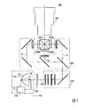
図2は、光源装置200の構成を示す断面図である。光源装置200は、光源ユニット210と、放電灯点灯装置(放電灯駆動装置)10と、を備えている。図2には、光源ユニット210の断面図が示されている。光源ユニット210は、主反射鏡112と、放電灯90と、副反射鏡113と、を備えている。
FIG. 2 is a cross-sectional view showing the configuration of the
放電灯点灯装置10は、放電灯90に駆動電流Iを供給して放電灯90を点灯させる。主反射鏡112は、放電灯90から放出された光を照射方向Dに向けて反射する。照射方向Dは、放電灯90の光軸AXと平行である。
The discharge
放電灯90の形状は、照射方向Dに沿って延びる棒状である。放電灯90の一方の端部を第1端部90e1とし、放電灯90の他方の端部を第2端部90e2とする。放電灯90の材料は、例えば、石英ガラス等の透光性材料である。放電灯90の中央部は球状に膨らんでおり、その内部は放電空間91である。放電空間91には、希ガス、金属ハロゲン化合物等を含む放電媒体であるガスが封入されている。
The shape of the
放電空間91には、第1電極92および第2電極93の先端が突出している。第1電極92は、放電空間91の第1端部90e1側に配置されている。第2電極93は、放電空間91の第2端部90e2側に配置されている。第1電極92および第2電極93の形状は、光軸AXに沿って延びる棒状である。放電空間91には、第1電極92および第2電極93の電極先端部が、所定距離だけ離れて対向するように配置されている。第1電極92および第2電極93の材料は、例えば、タングステン等の金属である。
The tips of the
放電灯90の第1端部90e1に、第1端子536が設けられている。第1端子536と第1電極92とは、放電灯90の内部を貫通する導電性部材534により電気的に接続されている。同様に、放電灯90の第2端部90e2に、第2端子546が設けられている。第2端子546と第2電極93とは、放電灯90の内部を貫通する導電性部材544により電気的に接続されている。第1端子536および第2端子546の材料は、例えば、タングステン等の金属である。導電性部材534,544の材料としては、例えば、モリブデン箔が利用される。
A
第1端子536および第2端子546は、放電灯点灯装置10に接続されている。放電灯点灯装置10は、第1端子536および第2端子546に、放電灯90を駆動するための駆動電流Iを供給する。その結果、第1電極92および第2電極93の間でアーク放電が起きる。アーク放電により発生した光(放電光)は、破線の矢印で示すように、放電位置から全方向に向かって放射される。
The
主反射鏡112は、固定部材114により、放電灯90の第1端部90e1に固定されている。主反射鏡112は、放電光のうち、照射方向Dと反対側に向かって進む光を照射方向Dに向かって反射する。主反射鏡112の反射面(放電灯90側の面)の形状は、放電光を照射方向Dに向かって反射できる範囲内において、特に限定されず、例えば、回転楕円形状であっても、回転放物線形状であってもよい。例えば、主反射鏡112の反射面の形状を回転放物線形状とした場合、主反射鏡112は、放電光を光軸AXに略平行な光に変換することができる。これにより、平行化レンズ305を省略することができる。
The
副反射鏡113は、固定部材522により、放電灯90の第2端部90e2側に固定されている。副反射鏡113の反射面(放電灯90側の面)の形状は、放電空間91の第2端部90e2側の部分を囲む球面形状である。副反射鏡113は、放電光のうち、主反射鏡112が配置された側と反対側に向かって進む光を主反射鏡112に向かって反射する。これにより、放電空間91から放射される光の利用効率を高めることができる。
The
固定部材114,522の材料は、放電灯90からの発熱に耐え得る耐熱材料である範囲内において、特に限定されず、例えば、無機接着剤である。主反射鏡112および副反射鏡113と放電灯90との配置を固定する方法としては、主反射鏡112および副反射鏡113を放電灯90に固定する方法に限らず、任意の方法を採用できる。例えば、放電灯90と主反射鏡112とを、独立にプロジェクター500の筐体(図示せず)に固定してもよい。副反射鏡113についても同様である。
The material of the fixing
以下、プロジェクター500の回路構成について説明する。
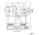
図3は、本実施形態のプロジェクター500の回路構成の一例を示す図である。プロジェクター500は、図1に示した光学系の他、画像信号変換部510と、直流電源装置80と、液晶パネル560R,560G,560Bと、画像処理装置570と、CPU(Central Processing Unit)580と、を備えている。
Hereinafter, the circuit configuration of the
FIG. 3 is a diagram showing an example of the circuit configuration of the
画像信号変換部510は、外部から入力された画像信号502(輝度−色差信号やアナログRGB信号など)を所定のワード長のデジタルRGB信号に変換して画像信号512R,512G,512Bを生成し、画像処理装置570に供給する。
The image
画像処理装置570は、3つの画像信号512R,512G,512Bに対してそれぞれ画像処理を行う。画像処理装置570は、液晶パネル560R,560G,560Bをそれぞれ駆動するための駆動信号572R,572G,572Bを液晶パネル560R,560G,560Bに供給する。
The
直流電源装置80は、外部の交流電源600から供給される交流電圧を一定の直流電圧に変換する。直流電源装置80は、トランス(図示しないが、直流電源装置80に含まれる)の2次側にある画像信号変換部510、画像処理装置570およびトランスの1次側にある放電灯点灯装置10に直流電圧を供給する。
The DC
放電灯点灯装置10は、起動時に放電灯90の電極間に高電圧を発生し、絶縁破壊を生じさせて放電路を形成する。以後、放電灯点灯装置10は、放電灯90が放電を維持するための駆動電流Iを供給する。
The discharge
液晶パネル560R,560G,560Bは、前述した液晶ライトバルブ330R,330G,330Bにそれぞれ備えられている。液晶パネル560R,560G,560Bは、それぞれ駆動信号572R,572G,572Bに基づいて、前述した光学系を介して各液晶パネル560R,560G,560Bに入射される色光の透過率(輝度)を変調する。
The
CPU580は、プロジェクター500の点灯開始から消灯に至るまでの各種の動作を制御する。例えば、図3の例では、通信信号582を介して点灯命令や消灯命令を放電灯点灯装置10に出力する。CPU580は、放電灯点灯装置10から通信信号584を介して放電灯90の点灯情報を受け取る。
The
以下、放電灯点灯装置10の構成について説明する。
図4は、放電灯点灯装置10の回路構成の一例を示す図である。
放電灯点灯装置10は、図4に示すように、電力制御回路20と、極性反転回路30と、制御部40と、動作検出部60と、イグナイター回路70と、を備えている。
Hereinafter, the configuration of the discharge
FIG. 4 is a diagram showing an example of the circuit configuration of the discharge
As shown in FIG. 4, the discharge
電力制御回路20は、放電灯90に供給する駆動電力Wdを生成する。本実施形態においては、電力制御回路20は、直流電源装置80からの電圧を入力とし、入力電圧を降圧して直流電流Idを出力するダウンチョッパー回路で構成されている。
The power control circuit 20 generates the drive power Wd to be supplied to the
電力制御回路20は、スイッチ素子21、ダイオード22、コイル23およびコンデンサー24を含んで構成される。スイッチ素子21は、例えば、トランジスターで構成される。本実施形態においては、スイッチ素子21の一端は直流電源装置80の正電圧側に接続され、他端はダイオード22のカソード端子およびコイル23の一端に接続されている。
The power control circuit 20 includes a
コイル23の他端にコンデンサー24の一端が接続され、コンデンサー24の他端はダイオード22のアノード端子および直流電源装置80の負電圧側に接続されている。スイッチ素子21の制御端子には、後述する制御部40から電流制御信号が入力されてスイッチ素子21のON/OFFが制御される。電流制御信号には、例えば、PWM(Pulse Width Modulation)制御信号が用いられてもよい。
One end of the capacitor 24 is connected to the other end of the
スイッチ素子21がONすると、コイル23に電流が流れ、コイル23にエネルギーが蓄えられる。その後、スイッチ素子21がOFFすると、コイル23に蓄えられたエネルギーがコンデンサー24とダイオード22とを通る経路で放出される。その結果、スイッチ素子21がONする時間の割合に応じた直流電流Idが発生する。
When the
極性反転回路30は、電力制御回路20から入力される直流電流Idを所定のタイミングで極性反転させる。これにより、極性反転回路30は、制御された時間だけ継続する直流である駆動電流I、もしくは、任意の周波数を持つ交流である駆動電流Iを生成し、出力する。本実施形態において、極性反転回路30は、インバーターブリッジ回路(フルブリッジ回路)で構成されている。
The
極性反転回路30は、例えば、トランジスターなどで構成される第1のスイッチ素子31、第2のスイッチ素子32、第3のスイッチ素子33、および第4のスイッチ素子34を含んでいる。極性反転回路30は、直列接続された第1のスイッチ素子31および第2のスイッチ素子32と、直列接続された第3のスイッチ素子33および第4のスイッチ素子34と、が互いに並列接続された構成を有する。第1のスイッチ素子31、第2のスイッチ素子32、第3のスイッチ素子33、および第4のスイッチ素子34の制御端子には、それぞれ制御部40から極性反転制御信号が入力される。この極性反転制御信号に基づいて、第1のスイッチ素子31、第2のスイッチ素子32、第3のスイッチ素子33および第4のスイッチ素子34のON/OFF動作が制御される。
The
極性反転回路30においては、第1のスイッチ素子31および第4のスイッチ素子34と、第2のスイッチ素子32および第3のスイッチ素子33と、を交互にON/OFFさせる動作が繰り返される。これにより、電力制御回路20から出力される直流電流Idの極性が交互に反転する。極性反転回路30は、第1のスイッチ素子31と第2のスイッチ素子32との共通接続点、および第3のスイッチ素子33と第4のスイッチ素子34との共通接続点から、制御された時間だけ同一極性状態を継続する直流である駆動電流I、もしくは制御された周波数をもつ交流である駆動電流Iを生成し、出力する。
In the
すなわち、極性反転回路30は、第1のスイッチ素子31および第4のスイッチ素子34がONのときには第2のスイッチ素子32および第3のスイッチ素子33がOFFであり、第1のスイッチ素子31および第4のスイッチ素子34がOFFのときには第2のスイッチ素子32および第3のスイッチ素子33がONであるように制御される。したがって、第1のスイッチ素子31および第4のスイッチ素子34がONのときには、コンデンサー24の一端から第1のスイッチ素子31、放電灯90、第4のスイッチ素子34の順に流れる駆動電流Iが発生する。第2のスイッチ素子32および第3のスイッチ素子33がONのときには、コンデンサー24の一端から第3のスイッチ素子33、放電灯90、第2のスイッチ素子32の順に流れる駆動電流Iが発生する。
That is, in the
本実施形態において、電力制御回路20と極性反転回路30とを合わせた部分が放電灯駆動部230に対応する。すなわち、放電灯駆動部230は、放電灯90を駆動する駆動電流Iを放電灯90に供給する。
In the present embodiment, the portion where the power control circuit 20 and the
制御部40は、放電灯駆動部230を制御する。図4の例では、制御部40は、電力制御回路20および極性反転回路30を制御することにより、駆動電流Iが同一極性を継続する保持時間、駆動電流Iの電流値(駆動電力Wdの電力値)、周波数等のパラメーターを制御する。制御部40は、極性反転回路30に対して、駆動電流Iの極性反転タイミングにより、駆動電流Iが同一極性で継続する保持時間、駆動電流Iの周波数等を制御する極性反転制御を行う。制御部40は、電力制御回路20に対して、出力される直流電流Idの電流値を制御する電流制御を行う。
The
本実施形態において制御部40は、例えば、交流駆動と、直流駆動と、を実行可能である。交流駆動は、放電灯90に交流電流が供給される駆動である。直流駆動は、放電灯90に直流電流が供給される駆動である。各放電灯駆動によって放電灯90に供給される駆動電流Iの駆動電流波形については、後段において詳述する。
In the present embodiment, the
制御部40の構成は、特に限定されない。本実施形態においては、制御部40は、システムコントローラー41、電力制御回路コントローラー42、および極性反転回路コントローラー43を含んで構成されている。なお、制御部40は、その一部または全てを半導体集積回路で構成してもよい。
The configuration of the
システムコントローラー41は、電力制御回路コントローラー42および極性反転回路コントローラー43を制御することにより、電力制御回路20および極性反転回路30を制御する。システムコントローラー41は、動作検出部60が検出したランプ電圧(電極間電圧)Vlaおよび駆動電流Iに基づき、電力制御回路コントローラー42および極性反転回路コントローラー43を制御してもよい。
The
本実施形態においては、システムコントローラー41には、記憶部44が接続されている。
システムコントローラー41は、記憶部44に格納された情報に基づき、電力制御回路20および極性反転回路30を制御してもよい。記憶部44には、駆動電流Iの複数の駆動パターンDWが格納されている。より具体的には、記憶部44には、例えば、各駆動パターンDWを構成する各駆動に関する、駆動が実行される時間の長さ、駆動電流Iの電流値、周波数、周期数、極性、波形、変調パターン等の駆動パラメーターに関する情報が格納されている。駆動電流Iの各駆動パターンDWは、上述した交流駆動と直流駆動とのうち少なくとも一方を含んでいる。駆動パターンDWの詳細については、後段において詳述する。
In the present embodiment, the
The
電力制御回路コントローラー42は、システムコントローラー41からの制御信号に基づき、電力制御回路20へ電流制御信号を出力することにより、電力制御回路20を制御する。
The power
極性反転回路コントローラー43は、システムコントローラー41からの制御信号に基づき、極性反転回路30へ極性反転制御信号を出力することにより、極性反転回路30を制御する。
The polarity
制御部40は、機械学習を行う。制御部40は、機械学習に基づいて、記憶部44に格納された複数の駆動パターンDWのうちいずれか1つの駆動パターンDWを選択し、選択された駆動パターンDWを実行する。機械学習の詳細については、後段において詳述する。
The
制御部40は、専用回路を用いて実現され、上述した制御や後述する処理の各種制御を行うようにすることができる。これに対して、制御部40は、例えば、CPUが記憶部44に記憶された制御プログラムを実行することによりコンピューターとして機能し、これらの処理の各種制御を行うようにすることもできる。
The
図5は、制御部40の他の構成例について説明するための図である。図5に示すように、制御部40は、制御プログラムにより、電力制御回路20を制御する電流制御手段40−1、極性反転回路30を制御する極性反転制御手段40−2として機能するように構成されてもよい。
FIG. 5 is a diagram for explaining another configuration example of the
図4に示した例では、制御部40は、放電灯点灯装置10の一部として構成されている。これに対して、制御部40の機能の一部をCPU580が担うように構成されていてもよい。
In the example shown in FIG. 4, the
動作検出部60は、本実施形態においては、放電灯90のランプ電圧Vlaを検出して制御部40にランプ電圧情報を出力する電圧検出部を含む。また、動作検出部60は、駆動電流Iを検出して制御部40に駆動電流情報を出力する電流検出部などを含んでいてもよい。本実施形態においては、動作検出部60は、第1の抵抗61、第2の抵抗62および第3の抵抗63を含んで構成されている。
In the present embodiment, the
本実施形態において、動作検出部60の電圧検出部は、放電灯90と並列に、互いに直列接続された第1の抵抗61および第2の抵抗62で分圧した電圧によりランプ電圧Vlaを検出する。また、本実施形態において、電流検出部は、放電灯90に直列に接続された第3の抵抗63に発生する電圧により駆動電流Iを検出する。
In the present embodiment, the voltage detection unit of the
イグナイター回路70は、放電灯90の点灯開始時にのみ動作する。イグナイター回路70は、放電灯90の点灯開始時に放電灯90の電極間(第1電極92と第2電極93との間)を絶縁破壊して放電路を形成するために必要な高電圧(放電灯90の通常点灯時よりも高い電圧)を、放電灯90の電極間(第1電極92と第2電極93との間)に供給する。本実施形態においては、イグナイター回路70は、放電灯90と並列に接続されている。
The
図6Aおよび図6Bには、第1電極92および第2電極93の先端部分が示されている。第1電極92および第2電極93の先端にはそれぞれ突起552p,562pが形成されている。図6Aは、第1電極92が陽極として動作し、第2電極93が陰極として動作する第1極性状態を示している。第1極性状態では、放電により、第2電極93(陰極)から第1電極92(陽極)へ電子が移動する。陰極(第2電極93)からは電子が放出される。陰極(第2電極93)から放出された電子は陽極(第1電極92)の先端に衝突する。この衝突によって熱が生じ、陽極(第1電極92)の先端(突起552p)の温度が上昇する。
6A and 6B show the tip portions of the
図6Bは、第1電極92が陰極として動作し、第2電極93が陽極として動作する第2極性状態を示している。第2極性状態では、第1極性状態とは逆に、第1電極92から第2電極93へ電子が移動する。その結果、第2電極93の先端(突起562p)の温度が上昇する。
FIG. 6B shows a second polar state in which the
このように、放電灯90に駆動電流Iが供給されることで、電子が衝突する陽極の温度は上昇する。一方、電子を放出する陰極は、陽極に向けて電子を放出している間、温度は低下する。
By supplying the drive current I to the
第1電極92と第2電極93との電極間距離は、突起552p,562pの劣化とともに大きくなる。突起552p,562pが損耗するためである。電極間距離が大きくなると、第1電極92と第2電極93との間の抵抗が大きくなるため、ランプ電圧Vlaが大きくなる。したがって、ランプ電圧Vlaを参照することによって、電極間距離の変化、すなわち、放電灯90の劣化度合いを検出することができる。
The distance between the
なお、第1電極92と第2電極93とは、同様の構成であるため、以下の説明においては、代表して第1電極92についてのみ説明する場合がある。また、第1電極92の先端の突起552pと第2電極93の先端の突起562pとは、同様の構成であるため、以下の説明においては、代表して突起552pについてのみ説明する場合がある。
Since the
以下、本実施形態の制御部40による放電灯駆動部230の制御について説明する。本実施形態において制御部40は、交流駆動および直流駆動うち少なくとも1つの駆動によって放電灯駆動部230を制御する。
Hereinafter, the control of the discharge
本実施形態において制御部40は、後述の1つ以上の駆動を組み合わせた駆動パターンDWを複数実行可能である。本実施形態において各駆動パターンDWは、駆動パターンDWを構成する各駆動における駆動パラメーターのうち少なくとも1つが互いに異なる駆動電流波形を有する。
In the present embodiment, the
以下、各駆動について説明する。図7は、交流駆動において放電灯90に供給される駆動電流波形の一例を示す図である。図8Aおよび図8Bは、直流駆動において放電灯90に供給される駆動電流波形の一例を示す図である。図7、図8Aおよび図8Bにおいて、縦軸は駆動電流Iを示しており、横軸は時間Tを示している。駆動電流Iは、第1極性状態である場合を正とし、第2極性状態となる場合を負として示している。
Hereinafter, each drive will be described. FIG. 7 is a diagram showing an example of a drive current waveform supplied to the
図7に示す交流駆動において放電灯90に供給される駆動電流Iは、例えば、電流値Imと電流値−Imとの間で極性が複数回反転される矩形波交流電流である。図7に示す交流電流において、周期C1の長さは、一定である。図7に示す交流電流のデューティー比は、0.5(50%)である。
The drive current I supplied to the
図8Aに示す直流駆動において放電灯90に供給される駆動電流Iは、一定の電流値Imを有する第1極性の直流電流である。図8Bに示す直流駆動において放電灯90に供給される駆動電流Iは、一定の電流値−Imを有する第2極性の直流電流である。
The drive current I supplied to the
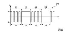
図9は、本実施形態において、放電灯90に供給される駆動電流Iの駆動パターンDWの一例を示す図である。図9において縦軸は駆動電流Iを示しており、横軸は時間Tを示している。
FIG. 9 is a diagram showing an example of a drive pattern DW of the drive current I supplied to the
図9に示される駆動パターンDWは、交流駆動および直流駆動から構成される。より具体的には、図9の駆動パターンDWは、第1交流駆動AC1、第1直流駆動DC1、第2交流駆動AC2、および第2直流駆動DC2から構成される。そして、この駆動パターンDWは、各交流駆動および各直流駆動に関して複数の駆動パラメーターを有する。例えば、第1交流駆動AC1は、駆動パラメーターとして、交流駆動の実行時間の長さta1および交流電流の第1周波数f1を有する。第1直流駆動DC1は、駆動パラメーターとして、直流駆動の実行時間の長さtd1および第1極性を有する。第2交流駆動AC2は、駆動パラメーターとして、交流駆動の実行時間の長さta2および交流電流の第2周波数f2を有する。第2直流駆動DC2は、駆動パラメーターとして、直流駆動の実行時間の長さtd2および第2極性を有する。 The drive pattern DW shown in FIG. 9 is composed of AC drive and DC drive. More specifically, the drive pattern DW of FIG. 9 is composed of a first AC drive AC1, a first DC drive DC1, a second AC drive AC2, and a second DC drive DC2. The drive pattern DW has a plurality of drive parameters for each AC drive and each DC drive. For example, the first AC drive AC1 has the length ta1 of the execution time of the AC drive and the first frequency f1 of the AC current as the drive parameters. The first DC drive DC1 has a DC drive execution time length td1 and a first polarity as drive parameters. The second AC drive AC2 has the length ta2 of the execution time of the AC drive and the second frequency f2 of the AC current as the drive parameters. The second DC drive DC2 has a DC drive execution time length td2 and a second polarity as drive parameters.
なお、図9の駆動パターンDWの場合、第1交流駆動AC1の実行時間の長さta1および第2交流駆動AC2の実行時間の長さta2は、同じとしており、また、第1交流駆動AC1の実行時間の長さta1および第2交流駆動AC2の実行時間の長さta2も、同じとしている。さらに、図9の駆動パターンDWの場合、第1交流駆動AC1における交流電流の第1周波数f1および第2交流駆動AC2における交流電流の第2周波数f2は、同じとしている。 In the case of the drive pattern DW of FIG. 9, the length of the execution time of the first AC drive AC1 ta1 and the length of the execution time of the second AC drive AC2 ta2 are the same, and the length of the execution time of the first AC drive AC1 is the same. The length of the execution time ta1 and the length of the execution time of the second AC drive AC2 ta2 are also the same. Further, in the case of the drive pattern DW of FIG. 9, the first frequency f1 of the alternating current in the first alternating current drive AC1 and the second frequency f2 of the alternating current in the second alternating current drive AC2 are the same.
第1周波数f1および第2周波数f2は、例えば、100Hz以上、1kHz以下である。第1交流駆動AC1の実行時間の長さta1および第2交流駆動AC2の実行時間の長さta2は、例えば、10ms(ミリ秒)以上、10s(秒)以下である。第1直流駆動DC1の実行時間の長さtd1および第2直流駆動DC2の実行時間の長さtd2は、例えば、10ms(ミリ秒)以上、40ms(ミリ秒)以下である。 The first frequency f1 and the second frequency f2 are, for example, 100 Hz or more and 1 kHz or less. The length of the execution time of the first AC drive AC1 ta1 and the length of the execution time of the second AC drive AC2 ta2 are, for example, 10 ms (milliseconds) or more and 10 s (seconds) or less. The length of the execution time of the first DC drive DC1 td1 and the length of the execution time of the second DC drive DC2 td2 are, for example, 10 ms (milliseconds) or more and 40 ms (milliseconds) or less.
複数の駆動パターンDWは、例えば、上記各駆動における各駆動パラメーターの数値範囲のうちから選択された複数の数値が適宜組み合わされて構成される。例えば、組み合わせとして用いる各駆動における駆動パラメーターの種類の合計は、2種類以上、6種類以下が好ましく、駆動パラメーターの種類ごとに用意する数値は、2つ以上、6つ以下が好ましい。これらを組み合わせて複数の駆動パターンDWを構成することで、好ましい数の駆動パターンDWが得られる。 The plurality of drive patterns DW are configured by, for example, appropriately combining a plurality of numerical values selected from the numerical range of each drive parameter in each of the above drives. For example, the total number of types of drive parameters in each drive used as a combination is preferably 2 or more and 6 or less, and the numerical values prepared for each type of drive parameter are preferably 2 or more and 6 or less. By combining these to form a plurality of drive pattern DWs, a preferable number of drive pattern DWs can be obtained.
例えば、前述の図9に示される駆動パターンDWで説明された駆動パラメーターは、交流駆動の実行時間の長さ、交流駆動における交流電流の周波数、直流駆動の実行時間の長さ、および直流駆動の極性であり、この場合、各駆動における駆動パラメーターの種類の合計は、4種類である。 For example, the drive parameters described in the drive pattern DW shown in FIG. 9 above are the length of the AC drive execution time, the frequency of the AC current in the AC drive, the length of the DC drive execution time, and the DC drive. It is a polarity, and in this case, the total number of types of drive parameters in each drive is four.
複数の駆動パターンDWは、上述した複数の駆動パラメーターのうちの少なくとも1つの駆動パラメーターの値が互いに異なる。駆動パターンDWの数は、例えば、3パターン以上、150パターン以下である。好ましくは、駆動パターンDWの数は、10パターン以上、100パターン以下である。より好ましくは、駆動パターンDW数は、20パターン以上、30パターン以下である。このように駆動パターンDWの数を設定することで、放電灯90の寿命をより向上できる。
In the plurality of drive patterns DW, the values of at least one of the plurality of drive parameters described above are different from each other. The number of drive patterns DW is, for example, 3 patterns or more and 150 patterns or less. Preferably, the number of drive patterns DW is 10 patterns or more and 100 patterns or less. More preferably, the number of drive patterns DW is 20 patterns or more and 30 patterns or less. By setting the number of drive patterns DW in this way, the life of the
次に、本実施形態の制御部40による各駆動パターンDWの切り換えについて説明する。制御部40は、機械学習に基づいて、駆動パターンDWを切り換える。本実施形態において制御部40は、ランプ電圧Vlaの変化に基づいて駆動パターンDWの評価を行い、この駆動パターンDWの評価に基づいて、駆動パターンDWの選択を行う。
Next, switching of each drive pattern DW by the
本実施形態においては、複数の駆動パターンDWの初期評価が行われる初期学習期間と、初期学習期間の後に設けられる定常学習期間と、が設けられる。図10は、初期学習期間における制御部40の制御手順の一例を示すフローチャートである。なお、以下の説明においては、駆動パターンDWは、N個設けられ、各駆動パターンDWには、それぞれ1番〜N番までの番号が振られているとする。
In the present embodiment, an initial learning period in which the initial evaluation of the plurality of drive patterns DW is performed and a steady learning period provided after the initial learning period are provided. FIG. 10 is a flowchart showing an example of the control procedure of the
図10に示すように、制御部40は、初期学習期間を開始した(ステップS11)後、1番〜N番までの駆動パターンDWのうちから、初期学習期間において選択していない駆動パターンDWを選択する(ステップS12)。制御部40は、例えば、選択していない駆動パターンDWをランダムで選択する。初期学習期間を開始した直後においては、いずれの駆動パターンDWも選択していないため、制御部40は、1番〜N番までの駆動パターンDWのうちから1つの駆動パターンDWを選択する。次に、動作検出部60の電圧検出部は、放電灯90のランプ電圧Vla1を検出し(ステップS13)、制御部40は、検出されたランプ電圧Vla1を記憶部44に記憶する。そして、制御部40は、選択された駆動パターンDWを実行する(ステップS14)。
As shown in FIG. 10, after starting the initial learning period (step S11), the
駆動パターンDWの実行を開始した後、制御部40は、現在選択されている駆動パターンDWの実行が開始されてから初期学習時間が経過したか否かを判断する(ステップS15)。初期学習時間の長さは、例えば、10min(分)以上、120min(分)以下である。現在選択されている駆動パターンDWの実行が開始されてから初期学習時間が経過していない場合(ステップS15:NO)、制御部40は、現在選択されている駆動パターンDWを実行し続ける。
After starting the execution of the drive pattern DW, the
一方、現在選択されている駆動パターンDWの実行が開始されてから初期学習時間が経過した場合(ステップS15:YES)、動作検出部60の電圧検出部は、放電灯90のランプ電圧Vla2を検出し(ステップS16)、制御部40は、検出されたランプ電圧Vla2を記憶部44に記憶する。そして、制御部40は、現在選択されている駆動パターンDWを評価する(ステップS17)。
On the other hand, when the initial learning time has elapsed since the execution of the currently selected drive pattern DW is started (step S15: YES), the voltage detection unit of the
本実施形態において駆動パターンDWの評価は、ランプ電圧Vlaの変化に基づいて行われる。具体的には、制御部40は、選択された駆動パターンDWを初期学習時間実行した後のランプ電圧Vla2の値と、選択された駆動パターンDWを実行する前のランプ電圧Vla1に対する、駆動パターンDWを初期学習時間実行した後のランプ電圧Vla2の差と、に基づいて、駆動パターンDWを評価する。以下の説明においては、駆動パターンDWを実行する前のランプ電圧Vla1に対する、駆動パターンDWを初期学習時間実行した後のランプ電圧Vla2の差を、第1変動電圧値と呼ぶ。
In the present embodiment, the evaluation of the drive pattern DW is performed based on the change of the lamp voltage Vla. Specifically, the
ここで、ランプ電圧Vlaには、目標数値範囲が設定されている。制御部40は、可能な限りランプ電圧Vlaを目標数値範囲に維持できるように、各駆動パターンDWの選択・実行を行う。目標数値範囲は、例えば、60V以上、65V未満である。駆動パターンDWの評価が比較的高くなる場合は、例えば、1つの駆動パターンDWを実行したことでランプ電圧Vla(1つの駆動パターンDWが初期学習時間実行された後のランプ電圧Vla2)が目標数値範囲内となった場合、1つの駆動パターンDWを実行したことでランプ電圧Vlaが目標数値範囲に近づいた場合、および1つの駆動パターンDWを実行する前後でランプ電圧Vlaを目標数値範囲内に維持できた場合等である。また、駆動パターンDWの評価が比較的低い場合は、例えば、1つの駆動パターンDWを実行したことでランプ電圧Vlaが目標数値範囲から外れた場合、および1つの駆動パターンDWを実行したことでランプ電圧Vlaが目標数値範囲から遠ざかった場合等である。
Here, a target numerical range is set for the lamp voltage Vla. The
一例として、1つの駆動パターンDWを初期学習時間実行した後のランプ電圧Vla2が目標数値範囲よりも大きい場合、かつ、第1変動電圧値が負の値である場合、選択された1つの駆動パターンDWの評価は比較的高い。また、1つの駆動パターンDWを初期学習時間実行した後のランプ電圧Vla2が目標数値範囲よりも大きい場合、かつ、第1変動電圧値が正の値である場合、選択された1つの駆動パターンDWの評価は比較的低い。一方、1つの駆動パターンDWを初期学習時間実行した後のランプ電圧Vla2が目標数値範囲よりも小さい場合、かつ、第1変動電圧値が負の値である場合、選択された1つの駆動パターンDWの評価は比較的低い。また、1つの駆動パターンDWを初期学習時間実行した後のランプ電圧Vla2が目標数値範囲よりも小さい場合、かつ、第1変動電圧値が正の値である場合、選択された1つの駆動パターンDWの評価は比較的高い。さらに、1つの駆動パターンDWを初期学習時間実行した後のランプ電圧Vla2が目標数値範囲内である場合には、第1変動電圧値の絶対値が小さいほど、選択された1つの駆動パターンDWの評価は比較的高く、一方で、第1変動電圧値の絶対値が大きいほど、選択された1つの駆動パターンDWの評価は比較的低い。 As an example, when the lamp voltage Vla2 after executing one drive pattern DW for the initial learning time is larger than the target numerical range and the first fluctuation voltage value is a negative value, one selected drive pattern is selected. The evaluation of DW is relatively high. Further, when the lamp voltage Vla2 after executing one drive pattern DW for the initial learning time is larger than the target numerical range and the first variable voltage value is a positive value, one selected drive pattern DW Evaluation is relatively low. On the other hand, when the lamp voltage Vla2 after executing one drive pattern DW for the initial learning time is smaller than the target numerical range and the first variable voltage value is a negative value, one selected drive pattern DW Evaluation is relatively low. Further, when the lamp voltage Vla2 after executing one drive pattern DW for the initial learning time is smaller than the target numerical range and the first variable voltage value is a positive value, one selected drive pattern DW Evaluation is relatively high. Further, when the lamp voltage Vla2 after executing one drive pattern DW for the initial learning time is within the target numerical range, the smaller the absolute value of the first variable voltage value, the more the selected one drive pattern DW. The evaluation is relatively high, while the larger the absolute value of the first fluctuation voltage value, the lower the evaluation of one selected drive pattern DW.
なお、第1変動電圧値が負の値であるとは、1つの駆動パターンDWを初期学習時間実行したことでランプ電圧Vlaが低下したことを意味する。第1変動電圧値が正の値であるとは、1つの駆動パターンDWを初期学習時間実行したことでランプ電圧Vlaが上昇したことを意味する。 In addition, the fact that the first fluctuation voltage value is a negative value means that the lamp voltage Vla is lowered by executing one drive pattern DW for the initial learning time. When the first variable voltage value is a positive value, it means that the lamp voltage Vla is increased by executing one drive pattern DW for the initial learning time.
選択されている駆動パターンDWを評価した後、制御部40は、初期学習期間において1番〜N番までの駆動パターンDWを全て実行したか否かを判断する(ステップS18)。1番〜N番までの駆動パターンDWのうちで初期学習期間において実行していない駆動パターンDWがある場合(ステップS18:NO)、制御部40は、別の駆動パターンDWを選択して実行し、評価する(ステップS12〜S17)。一方で、初期学習期間において1番〜N番までのNパターンの駆動パターンDWを全て実行した場合(ステップS18:YES)、制御部40は、初期学習期間を終了して、定常学習期間に移行する(ステップS19)。初期学習期間の長さは、例えば、10h(時間)未満である。
After evaluating the selected drive pattern DW, the
本実施形態において、選択された駆動パターンDWを実行する前のランプ電圧Vla1として、ステップS12において複数の駆動パターンDWのうちから選択していない駆動パターンDWを選択した後に、動作検出部60の電圧検出部によって放電灯90のランプ電圧Vlaを検出することとしたが、これに限られない。選択されたX番目の駆動パターンDWを実行する前のランプ電圧Vla1は、例えば、選択されたX番目の駆動パターンDWの1つ前に選択された(X−1)番目の駆動パターンDWが初期学習時間実行された後に検出されたランプ電圧Vla2としてもよい。このように制御することで、ステップS13におけるランプ電圧Vla1の検出が不要となり、初期評価の処理をより簡略化できる。
In the present embodiment, as the lamp voltage Vla1 before executing the selected drive pattern DW, the voltage of the
図11は、定常学習期間における制御部40の制御手順の一例を示すフローチャートである。図11では、定常学習期間における1サイクルを示している。定常学習期間において制御部40は、図11に示すような1サイクルを繰り返し実行する。図11に示すように、制御部40は、定常学習期間を開始した(ステップS21)後、1番〜N番までの駆動パターンDWの中から、定常学習期間において選択されていない駆動パターンDWと比較的評価の高い駆動パターンDWとのうち一方の駆動パターンDWを選択する(ステップS22〜S24)。なお、制御部40は、例えば、1番〜N番までの駆動パターンDWの中から駆動パターンDWをランダムで選択する。
FIG. 11 is a flowchart showing an example of the control procedure of the
より具体的には、例えば、制御部40は、1番〜N番までの駆動パターンDWの中から、定常学習期間において選択されていない駆動パターンDWと比較的評価の高い駆動パターンDWとのうち前者(定常学習期間において選択されていない駆動パターンDW)を選択するか否かを判断し(ステップS22)、比較的評価の高い駆動パターンDWを選択する場合(ステップS22:NO)、1番〜N番までの駆動パターンDWの中から比較的評価の高い駆動パターンDWを選択する(ステップS23)。制御部40は、例えば、1番〜N番までの駆動パターンDWのうち、評価が最も高い駆動パターンDW、すなわち、ランプ電圧Vlaをランプ電圧Vlaの目標数値範囲(所定電圧値)に最も近付ける駆動パターンDWを選択する。そして、制御部40は、ステップS23において選択された駆動パターンDWを実行する(ステップS26)。
More specifically, for example, the
一方で、制御部40は、定常学習期間において選択されていない駆動パターンDWである前者を選択する場合(ステップS22:YES)、1番〜N番までの駆動パターンDWの中から定常学習期間において選択されていない駆動パターンDWを選択する(ステップS24)。そして、定常学習期間において選択されていない駆動パターンDWが選択された場合、制御部40は、選択された駆動パターンDWが実行条件を満たすか否かを判断する(ステップS25)。実行条件は、例えば、選択された駆動パターンDWが前回選択され実行された際に、後述するステップS28において他の駆動パターンDWへ切り換えられていないことを含む。
On the other hand, when the
ステップS24において選択された駆動パターンDWが実行条件を満たす場合(ステップS25:YES)、ステップS26に移行し、制御部40は、選択された駆動パターンDWを実行する。一方、選択された駆動パターンDWが実行条件を満たさない場合(ステップS25:NO)、ステップS22に移行し、制御部40は、1番〜N番までの駆動パターンDWの中から他の駆動パターンDWを選択し、上述したのと同様の判断を行う。
If the drive pattern DW selected in step S24 satisfies the execution condition (step S25: YES), the process proceeds to step S26, and the
次に、選択された駆動パターンDWの実行を開始した後、制御部40は、現在選択されている駆動パターンDWの実行を開始してから定常学習時間が経過したか否かを判断する(ステップS27)。ステップS27において判断する定常学習時間は、例えば、初期学習期間におけるステップS15で判断する初期学習時間と同じである。すなわち、定常学習時間の長さは、例えば、10min(分)以上、120min(分)以下である。現在選択されている駆動パターンDWの実行が開始されてから定常学習時間が経過していない場合(ステップS27:NO)、制御部40は、現在の駆動パターンDWが切換条件(第1所定条件)を満たすか否かを判断する(ステップS28)。
Next, after starting the execution of the selected drive pattern DW, the
切換条件は、例えば、第1切換条件と、第2切換条件とのいずれか1つを満たすことを含む。第1切換条件は、現在の駆動パターンDWの実行中に、定常学習時間内で検出されたランプ電圧Vlaの変化(変動電圧値)の絶対値が第1所定値以上となり、かつ、検出されたランプ電圧Vlaが目標数値範囲から外れることである。第2切換条件は、現在の駆動パターンDWの実行が開始してから経過した時間が第1時間以下の場合に、ランプ電圧Vlaの変化の絶対値が第2所定値以上となることを含む。第1時間は、定常学習時間よりも小さく、例えば、5min(分)である。第2所定値は、第1所定値よりも小さい。第1所定値は、例えば、5Vである。第2所定値は、例えば、3Vである。 The switching condition includes, for example, satisfying any one of the first switching condition and the second switching condition. The first switching condition is that the absolute value of the change (fluctuation voltage value) of the lamp voltage Vla detected within the steady learning time during the execution of the current drive pattern DW becomes the first predetermined value or more and is detected. The lamp voltage Vla is out of the target numerical range. The second switching condition includes that the absolute value of the change of the lamp voltage Vla becomes the second predetermined value or more when the time elapsed from the start of the execution of the current drive pattern DW is the first hour or less. The first time is smaller than the steady learning time, for example, 5 min (minutes). The second predetermined value is smaller than the first predetermined value. The first predetermined value is, for example, 5V. The second predetermined value is, for example, 3V.
すなわち、第1時間以下においてはランプ電圧Vlaの変化の絶対値が第1所定値よりも小さい第2所定値以上となった場合でも切換条件(第2切換条件)を満たすこととし、第1時間を超えた場合においてはランプ電圧Vlaの変化が第2所定値よりも大きい第1所定値以上とならなければ切換条件(第1切換条件)を満たさないこととする。このような関係とすることで、制御部40は、現在選択されている駆動パターンDWの実行時間とランプ電圧Vlaとに基づいて、現在選択されている駆動パターンDWの切換を段階的に判断する。
That is, in the first hour or less, the switching condition (second switching condition) is satisfied even when the absolute value of the change of the lamp voltage Vla is equal to or more than the second predetermined value smaller than the first predetermined value, and the first time is satisfied. If it exceeds, the switching condition (first switching condition) is not satisfied unless the change of the lamp voltage Vla becomes equal to or more than the first predetermined value larger than the second predetermined value. With such a relationship, the
現在選択されている駆動パターンDWが切換条件を満たす場合(ステップS28:YES)、制御部40は、現在の放電灯90の状態においては、現在選択されている駆動パターンDWが放電灯90の寿命を向上させるために好ましくない駆動パターンDWであると判断する。そして、制御部40は、現在選択されている駆動パターンDWの評価を下げる。
When the currently selected drive pattern DW satisfies the switching condition (step S28: YES), the
その後、制御部40は、上述したのと同様にして、ステップS22〜ステップS26を実行し、次の駆動パターンDWの選択・実行を行う。このように、制御部40は、駆動パターンDW実行時において、ランプ電圧Vlaの変化が切換条件を満たす場合、現在選択されている駆動パターンDWから他の駆動パターンDWに切り換える。
After that, the
一方で、現在の駆動パターンDWが切換条件を満たさない場合(ステップS28:NO)、制御部40は、定常学習時間が経過するまで現在選択されている駆動パターンDWを実行する。そして、現在の駆動パターンDWの実行を開始してから定常学習時間が経過した場合(ステップS27:YES)、動作検出部60の電圧検出部は、放電灯90のランプ電圧Vlaを検出し(ステップS29)、制御部40は、検出されたランプ電圧Vlaを記憶部44に記憶する。その後、制御部40は、現在選択されている駆動パターンDWを評価する(ステップS30)。
On the other hand, when the current drive pattern DW does not satisfy the switching condition (step S28: NO), the
ステップS30における駆動パターンDWの評価は、例えば、初期学習期間のステップS17における駆動パターンDWの評価と同様である。すなわち、制御部40は、選択された駆動パターンDWを定常学習時間実行した後のランプ電圧Vlaの値と、選択された駆動パターンDWを実行する前のランプ電圧Vlaに対する駆動パターンDWを定常学習時間実行した後のランプ電圧Vlaの差と、に基づいて、駆動パターンDWを評価する。以下の説明においては、駆動パターンDWを実行する前のランプ電圧Vlaに対する駆動パターンDWを定常学習時間実行した後のランプ電圧Vlaの差を、第2変動電圧値と呼ぶ。
The evaluation of the drive pattern DW in step S30 is the same as the evaluation of the drive pattern DW in step S17 of the initial learning period, for example. That is, the
ステップS30において制御部40は、定常学習期間において選択された駆動パターンDWの再評価を行う。すなわち、制御部40は、各駆動パターンDWに対し、初期学習期間において行われた評価、および現時点よりも前の定常学習期間において行われた評価を更新する。
In step S30, the
続いて、制御部40は、現在選択されている駆動パターンDWが連続実行条件(第2所定条件)を満たすか否か判断する(ステップS31)。連続実行条件は、第1連続実行条件と、第2連続実行条件と、第3連続実行条件とのいずれか1つを満たすことを含む。第1連続実行条件、第2連続実行条件、および第3連続実行条件の各々は、連続実行回数が所定回数以下であることを含む。連続実行回数に関する所定回数は、例えば、2回以上、15回以下である。
Subsequently, the
そして、第1連続実行条件は、選択された駆動パターンDWを定常学習時間実行した後のランプ電圧Vlaが目標数値範囲よりも大きく、かつ、第2変動電圧値が負の値であることである。第2連続実行条件は、選択された駆動パターンDWの実行前後でランプ電圧Vlaが目標数値範囲内に含まれていることである。第3連続実行条件は、選択された駆動パターンDWを定常学習時間実行した後のランプ電圧Vlaが目標数値範囲よりも小さく、かつ、第2変動電圧値が正の値であることである。 The first continuous execution condition is that the lamp voltage Vla after the selected drive pattern DW is executed for the steady learning time is larger than the target numerical range, and the second variable voltage value is a negative value. .. The second continuous execution condition is that the lamp voltage Vla is included in the target numerical range before and after the execution of the selected drive pattern DW. The third continuous execution condition is that the lamp voltage Vla after executing the selected drive pattern DW for a steady learning time is smaller than the target numerical range, and the second variable voltage value is a positive value.
現在の駆動パターンDWが連続実行条件を満たす場合(ステップS31:YES)、制御部40は、現在の放電灯90の状態においては、現在選択されている駆動パターンDWが放電灯90の寿命を向上させるために好ましい駆動パターンDWであると判断する。そして、制御部40は、現在選択されている駆動パターンDWを、次に実行する駆動パターンDWとして再び選択する(ステップS32)。そして、ステップS26へ移行し、制御部40は、今回実行する駆動パターンDWとして選択された前回の駆動パターンDWを連続して実行する。
When the current drive pattern DW satisfies the continuous execution condition (step S31: YES), in the state of the
以上に説明したように、本実施形態において制御部40は、選択された1つの駆動パターンDWを定常学習時間実行した前後のランプ電圧Vlaの変化が連続実行条件を満たす場合、同じ駆動パターンDWを複数回連続して実行する。
As described above, in the present embodiment, the
一方で、現在の駆動パターンDWが連続実行条件を満たさない場合(ステップS31:NO)、制御部40は、ステップS22〜S26において駆動パターンDWの選択および実行を所定回数実行したか否かを判断する(ステップS33)。
On the other hand, when the current drive pattern DW does not satisfy the continuous execution condition (step S31: NO), the
駆動パターンDWの選択および実行を所定回数実行していない場合(ステップS33:NO)、ステップS22へ移行して、再び駆動パターンDWの選択を行う。1サイクルの定常学習期間における駆動パターンDWの選択および実行に関する所定回数は、例えば、駆動パターンDWの個数Nよりも大きい。 If the selection and execution of the drive pattern DW has not been executed a predetermined number of times (step S33: NO), the process proceeds to step S22, and the drive pattern DW is selected again. The predetermined number of times for selecting and executing the drive pattern DW in one cycle of steady learning period is, for example, larger than the number N of the drive pattern DWs.
駆動パターンDWの選択および実行を所定回数実行した場合(ステップS33:YES)、制御部40は、定常学習期間の1サイクルを終了する(ステップS34)。制御部40は、以上のような1サイクルを繰り返して、定常学習期間を実行し続ける。次の1サイクルは、駆動パターンDWの選択および実行の回数がリセットされること以外は、定常学習期間の前回のサイクルから各パラメーターを引き継いだ状態で実行される。
When the selection and execution of the drive pattern DW is executed a predetermined number of times (step S33: YES), the
以上のようにして、制御部40は、初期学習期間と定常学習期間とによって機械学習を行い、実行する駆動パターンDWを選択する。初期学習期間は、例えば、プロジェクター500が初めて点灯された後に1回のみ行われる。定常学習期間は、例えば、初期学習期間が終了した後、プロジェクター500が点灯している間、常時設けられる。例えば、プロジェクター500の電源がOFFにされた後、再びONにされた際には、制御部40は、前回電源がOFFにされた際に実行していた期間を、中断されたところから再開する。
As described above, the
例えば、従来においては、ランプ電圧Vlaの値と駆動電力Wdの値とに対応した駆動パターンDWが予め設定されていたため、ランプ電圧Vlaおよび駆動電力Wdが同じ値である場合には、実行される駆動パターンDWは、予め設定された1つの駆動パターンDWであった。 For example, in the past, since the drive pattern DW corresponding to the value of the lamp voltage Vla and the value of the drive power Wd was set in advance, it is executed when the lamp voltage Vla and the drive power Wd are the same value. The drive pattern DW was one preset drive pattern DW.
これに対して、本実施形態では、機械学習によって駆動パターンDWが選択されるため、例えば、ランプ電圧Vlaが所定の電圧値であり駆動電力Wdが所定の電力値である場合、少なくとも1つの駆動パラメーターが互いに異なる複数の駆動パターンDWが実行される。すなわち、例えば、制御部40、放電灯90に供給される駆動電力Wdが所定の電力帯であり、かつ、放電灯90のランプ電圧Vlaが所定の電圧値である場合に、少なくとも2つ(本実施形態では、例えば少なくとも3つ)の駆動パターンDWを実行する。この少なくとも2つの駆動パターンDWは、1つの駆動パターンDWを構成する駆動における複数の駆動パラメーターのうちの少なくとも1つの駆動パラメーターの値が互いに異なる駆動パターンDWである。すなわち、ランプ電圧Vlaを一定とし、かつ、駆動電力Wdの電力帯を一定として放電灯90に供給される駆動電流Iの駆動パターンDWを検出する場合、少なくとも2つ以上の異なる駆動パターンDWを検出可能である。なお、所定の電力帯とは、例えば、幅が10W以内程度の駆動電力Wdの数値範囲である。
On the other hand, in the present embodiment, since the drive pattern DW is selected by machine learning, for example, when the lamp voltage Vla is a predetermined voltage value and the drive power Wd is a predetermined power value, at least one drive is performed. A plurality of drive patterns DW having different parameters are executed. That is, for example, when the drive power Wd supplied to the
本実施形態においては、放電灯90に供給される駆動電力Wdが所定の電力帯であり、かつ、放電灯90のランプ電圧Vlaが所定の電圧値である場合に、例えば少なくとも3つの駆動パターンDWが実行される。例えば、3つの駆動パターンDWは、第1駆動パターン、第2駆動パターン、および第3駆動パターンであり、それぞれが図9に示されるように、交流駆動および直流駆動から構成されるとする。この場合の駆動パラメーターを、交流電流の周波数、交流駆動の実行時間の長さ、および直流駆動の実行時間の長さの3種類とした場合、例えば、第1駆動パターンについて、交流電流の周波数は400Hzであり、交流駆動の実行時間の長さは100msであり、直流駆動の実行時間の長さは10msである。第2駆動パターンについて、交流電流の周波数は400Hzであり、交流駆動の実行時間の長さは50msであり、直流駆動の実行時間の長さは10msである。第3駆動パターンについて、交流電流の周波数は300Hzであり、交流駆動の実行時間の長さは100msであり、直流駆動の実行時間の長さは10msである。第1駆動パターン、第2駆動パターン、および第3駆動パターンは、これら3つの駆動パターンDWのうちの各2つの駆動パターンDWの間で、複数の駆動パラメーターのうちの少なくとも1つの駆動パラメーターの値が互いに異なる駆動パターンDWである。
In the present embodiment, when the drive power Wd supplied to the
また、上述したように機械学習によって駆動パターンDWの選択・実行を行うと、放電灯90のランプ電圧Vlaが所定の電圧値である場合、放電灯90の累積点灯時間あるいは放電灯90の個体が異なることで、選択・実行される駆動パターンDWが異なる。すなわち、制御部40は、放電灯90のランプ電圧Vlaが所定の電圧値である場合、放電灯90の累積点灯時間および放電灯90の個体のうちの少なくとも一方に応じて、少なくとも2つの駆動パターンDW、例えば第1駆動パターンおよび第2駆動パターンを実行する。この場合、この2つの駆動パターンDWにおける駆動電力Wdの電力帯は、所定の電力値であってもよいし、異なってもよい。
Further, when the drive pattern DW is selected and executed by machine learning as described above, when the lamp voltage Vla of the
第1駆動パターンと第2駆動パターンとは、複数の駆動パターンDWのうちの任意の2つの駆動パターンDWである。第1駆動パターンと第2駆動パターンとは、各駆動パターンを構成する駆動における複数の駆動パラメーターのうち少なくとも1つの駆動パラメーターの値が互いに異なる。なお、累積点灯時間は、放電灯90が点灯された時間の総計である。すなわち、累積点灯時間は、放電灯90が初めて点灯したときから積算された放電灯90の点灯時間である。
The first drive pattern and the second drive pattern are arbitrary two drive patterns DW among the plurality of drive pattern DWs. In the first drive pattern and the second drive pattern, the values of at least one drive parameter among the plurality of drive parameters in the drive constituting each drive pattern are different from each other. The cumulative lighting time is the total time when the
具体的には、例えば、制御部40は、ランプ電圧Vlaが所定の電圧値であり、かつ、累積点灯時間が第1累積点灯時間である場合、第1駆動パターンを実行し、ランプ電圧Vlaが所定の電圧値であり、かつ、累積点灯時間が第1累積点灯時間とは異なる第2累積点灯時間である場合、第2駆動パターンを実行する。すなわち、ランプ電圧Vlaを一定として放電灯90に供給される駆動電流Iの駆動パターンDWを検出する場合、放電灯90の累積点灯時間が変わると、異なる駆動パターンDWを少なくとも2つ以上検出可能である。
Specifically, for example, when the lamp voltage Vla is a predetermined voltage value and the cumulative lighting time is the first cumulative lighting time, the
また、例えば、制御部40は、ランプ電圧Vlaが所定の電圧値であり、かつ、放電灯90が第1個体である場合、第1駆動パターンを実行し、ランプ電圧Vlaが所定の電圧値であり、かつ、放電灯90が第1個体とは異なる第2個体である場合、第2駆動パターンを実行する。すなわち、ランプ電圧Vlaを一定として放電灯90に供給される駆動電流Iの駆動パターンDWを検出する場合、放電灯90の個体が変わると、異なる駆動パターンDWを少なくとも2つ以上検出することが可能である。
Further, for example, when the lamp voltage Vla is a predetermined voltage value and the
上述した制御を行う制御部40を備える放電灯点灯装置10は、放電灯駆動方法としても表現できる。すなわち、本実施形態の放電灯駆動方法の一つの態様は、第1電極92および第2電極93を有する放電灯90に駆動電流Iを供給して、放電灯90を駆動する放電灯駆動方法であって、駆動電流Iの複数の駆動パターンDWに従って、放電灯90に駆動電流Iを供給し、複数の駆動パターンDWは、それぞれ複数の駆動パラメーターを有し、放電灯90のランプ電圧Vlaが所定の電圧値である場合、放電灯90の累積点灯時間および放電灯90の個体のうちの少なくとも一方に応じて、複数の駆動パラメーターのうち少なくとも1つの駆動パラメーターの値が互いに異なる第1駆動パターンおよび第2駆動パターンを実行することを特徴とする。
The discharge
なお、複数の駆動パラメーターのうち少なくとも1つの駆動パラメーターの値が互いに異なるとは、例えば2つの駆動パターンDWの間で、各駆動パターンDWを構成する駆動が異なる場合を含む。より具体的には、例えば、第1駆動パターンが交流駆動で構成され、第2駆動パターンが直流駆動および交流駆動で構成され、かつ、第1駆動パターンにおける交流駆動に関する各駆動パラメーターと第2駆動パターンにおける交流駆動に関する各パラメーターとが同じである場合も、第1駆動パターンと第2駆動パターンとは、少なくとも1つの駆動パラメーターの値が互いに異なる駆動パターンDWとする。この場合、第1駆動パターンには直流駆動が含まれないため、第1駆動パターンにおける直流駆動に関する駆動パラメーターをゼロとみなす。これにより、この場合において第1駆動パターンと第2駆動パターンとは、直流駆動に関する駆動パラメーターが互いに異なる。 The fact that the values of at least one drive parameter among the plurality of drive parameters are different from each other includes, for example, a case where the drives constituting each drive pattern DW are different between the two drive patterns DW. More specifically, for example, the first drive pattern is configured by AC drive, the second drive pattern is configured by DC drive and AC drive, and each drive parameter and the second drive related to AC drive in the first drive pattern are configured. Even when each parameter related to AC drive in the pattern is the same, the first drive pattern and the second drive pattern are drive patterns DW in which the values of at least one drive parameter are different from each other. In this case, since the first drive pattern does not include the DC drive, the drive parameter related to the DC drive in the first drive pattern is regarded as zero. As a result, in this case, the first drive pattern and the second drive pattern have different drive parameters related to DC drive.
本実施形態によれば、上述したようにして、制御部40は、放電灯90のランプ電圧Vlaが所定の電圧値である場合、放電灯90の累積点灯時間および放電灯90の個体のうちの少なくとも一方に応じて、複数の駆動パラメーターのうち少なくとも1つの駆動パラメーターの値が互いに異なる第1駆動パターンおよび第2駆動パターンを実行する。そのため、制御部40が累積点灯時間に応じて駆動パターンDWを実行する場合、同じランプ電圧Vlaであっても、放電灯90を駆動する時間によって、実行される駆動パターンDWを異ならせることができる。これにより、放電灯90に個体差がある場合であっても、好適な駆動パターンDWを実行しやすい。一方、制御部40が放電灯90の個体に応じて駆動パターンDWを実行する場合、同じランプ電圧Vlaであっても、放電灯90の個体によって、実行される駆動パターンDWを異ならせることができる。これにより、放電灯90に個体差がある場合であっても、好適な駆動パターンDWを実行しやすい。したがって、本実施形態によれば、放電灯90の個体差によらず、放電灯90の寿命を向上させることができる。
According to the present embodiment, as described above, when the lamp voltage Vla of the
また、本実施形態によれば、上述したようにして、制御部40は、機械学習に基づいて、複数の駆動パターンDWのうちからいずれか1つの駆動パターンDWを選択して、選択した駆動パターンDWを実行する。そのため、放電灯90に個体差がある場合であっても、機械学習を行うことで、放電灯90の個体差に応じて、第1駆動パターンと第2駆動パターンとのうちから好適な駆動パターンDWを選択することができる。したがって、本実施形態によれば、放電灯90の個体差によらず、放電灯90の寿命をより向上させることができる。
Further, according to the present embodiment, as described above, the
また、放電灯90に供給される駆動電力Wdが変化すると、第1電極92の突起552pの溶融度合い、および成長度合いが変化する。そのため、従来では、放電灯90に供給される駆動電力Wdごとに、ランプ電圧Vlaに応じて、放電灯90に供給される駆動電流Iの好適な駆動パターンDWを決め、記憶部44に格納しておく必要があった。したがって、全ての駆動電力Wdごとにランプ電圧Vlaに応じた駆動パターンDWを設定しておくことは困難であり、予め決められた複数種類の駆動電力Wdにしか、放電灯90に供給される駆動電力Wdを変更できない仕様となっていた。
Further, when the driving power Wd supplied to the
これに対して、本実施形態によれば、機械学習に基づいて駆動パターンDWが選択されるため、駆動電力Wdを変化させた場合であっても、駆動電力Wdの変化に応じて、好適な駆動パターンDWを選択することができる。これにより、放電灯90に供給される駆動電力Wdを容易に多段階で変化させることが可能となる。したがって、例えば、使用者が、駆動電力Wdを任意に変化させて、プロジェクター500から投射される映像の輝度を自由に変更することが可能となる。そのため、例えば、駆動電力Wdを比較的小さくして、プロジェクター500の消費電力を好適に抑えつつ、放電灯90の寿命を向上させることも可能となる。
On the other hand, according to the present embodiment, since the drive pattern DW is selected based on machine learning, even when the drive power Wd is changed, it is suitable according to the change in the drive power Wd. The drive pattern DW can be selected. This makes it possible to easily change the drive power Wd supplied to the
また、駆動電力Wdを任意に変更することが可能となるため、放電灯90の寿命を向上させる際に変化させる駆動パターンDWの駆動パラメーターの一つとして、駆動電力Wdを用いることも可能となる。これにより、放電灯90の寿命をより向上させることができる。例えば、プロジェクター500の筐体には、駆動電力Wdを変化させるための操作部を設けてもよい。
Further, since the drive power Wd can be arbitrarily changed, it is also possible to use the drive power Wd as one of the drive parameters of the drive pattern DW to be changed when the life of the
また、本実施形態によれば、制御部40は、ランプ電圧Vlaの変化に基づいて駆動パターンDWの選択を行う。そのため、ランプ電圧Vlaを検出することで、駆動パターンDWの選択を行うことができ、機械学習を好適かつ容易に行うことができる。
Further, according to the present embodiment, the
また、本実施形態によれば、制御部40は、選択された駆動パターンDWの実行時において、検出されたランプ電圧Vlaの変化が切換条件を満たす場合、選択された駆動パターンDWから他の駆動パターンDWに切り換える。そのため、選択された駆動パターンDWが、そのときの放電灯90の状態に対して寿命を向上させるのに好ましくない駆動パターンDWである場合に、駆動パターンDWを他の好適な駆動パターンDWへ切り換えられる。したがって、放電灯90の寿命が低下することを抑制できる。
Further, according to the present embodiment, when the change of the detected lamp voltage Vla satisfies the switching condition at the time of executing the selected drive pattern DW, the
また、上述したように、切換条件を満たした駆動パターンDWは、評価を下げられ、かつ、ステップS24において次に当該切換条件を満たした駆動パターンDWが選択され、ステップS25において当該切換条件を満たした駆動パターンDWが実行条件を満たすか判断される際に、実行条件を満たさないと判断される。すなわち、制御部40は、所定期間の間、当該切換条件を満たした駆動パターンDWを実行しない。そのため、本実施形態によれば、放電灯90の寿命を低下させる可能性が高い駆動パターンDWが実行されることを抑制でき、放電灯90の寿命をより向上させることができる。
Further, as described above, the drive pattern DW satisfying the switching condition is evaluated lower, and the drive pattern DW satisfying the switching condition is selected next in step S24, and the switching condition is satisfied in step S25. When it is determined whether the drive pattern DW satisfies the execution condition, it is determined that the execution condition is not satisfied. That is, the
上述したように制御部40は、選択された駆動パターンDWの実行を開始してから定常学習時間が経過した場合に、次の駆動パターンDWを選択するため、駆動パターンDWの実行時間(所定時間)の長さは基本的には、定常学習時間の長さと同じになる。しかし、定常学習期間において選択された駆動パターンDWは、放電灯90の状態によって、定常学習時間が経過する前に途中で他の駆動パターンDWへ切り換えられることがあるため、同じ駆動パターンDWであっても、1つの駆動パターンDWの実行を開始してから次の駆動パターンDWに切り換えられるまでの、選択された1つの駆動パターンDWの実行時間(所定時間)が変化する場合がある。
As described above, the
すなわち、制御部40は、ランプ電圧Vlaに基づいて、複数の駆動パターンDWのうちの所定の駆動パターンDWが実行される実行時間(所定時間)の長さを変化させる。そのため、ランプ電圧Vlaの変化に応じて、適宜駆動パターンDWを切り換えることができ、放電灯90の寿命をより向上できる。
That is, the
また、複数の駆動パターンDWのうちの所定の駆動パターンDWが実行される実行時間の長さは、上述したようにして変化するため、放電灯90の累積点灯時間に応じて変化する。また、複数の駆動パターンDWのうちの所定の駆動パターンが実行される実行時間の長さは、上述したようにして変化するため、放電灯90の個体に応じて変化する。選択された駆動パターンDWが途中で他の駆動パターンDWへ切り換えられた場合、当該選択された駆動パターンDWの実行時間(所定時間)は、定常学習時間よりも短い。
Further, since the length of the execution time in which the predetermined drive pattern DW among the plurality of drive pattern DWs is executed changes as described above, it changes according to the cumulative lighting time of the
また、例えば、評価が最も高い駆動パターンDW、すなわち、放電灯90のランプ電圧Vlaを目標数値範囲に最も近付ける駆動パターンDWであっても、常に同じ駆動パターンDWを実行する場合には、第1電極92の突起552pが成長しにくくなる場合があり、放電灯90の寿命を十分に向上させにくくなる場合がある。また、例えば、放電灯90の第1電極92の突起552pの溶融度合いおよび成長度合いは、放電灯90の劣化、すなわち累積点灯時間の増加に伴って変化する。そのため、ある時点において放電灯90の寿命を向上させるために好適な駆動パターンDWであっても、別の時点において放電灯90の寿命を向上させるために不適な駆動パターンDWとなることがある。
Further, for example, even if the drive pattern DW has the highest evaluation, that is, the drive pattern DW in which the lamp voltage Vla of the
これに対して、本実施形態によれば、制御部40は、定常学習期間の1サイクルにおいて、N個の駆動パターンDWの中から選択されていない駆動パターンDWおよび比較的評価の高い駆動パターンDWのうち一方を選択・実行する。そのため、1サイクル内において、評価の最も高い駆動パターンDWを含む比較的評価の高い駆動パターンDWと、それ以外の駆動パターンDWと、の両方が実行される。すなわち、本実施形態の制御部40は、一定の期間内において、複数の駆動パターンDWのうち評価の最も高い駆動パターンDWを含む比較的評価の高い駆動パターンDW(以下、高評価駆動パターンDWmと呼ぶ)と、複数の駆動パターンDWのうち高評価駆動パターンDWmよりも評価の低い駆動パターンDW(以下、他の駆動パターンDWeと呼ぶ)と、の両方を実行する。これにより、評価の高い高評価駆動パターンDWmの間に、高評価駆動パターンDWmよりも評価が低い他の駆動パターンDWeを実行することができ、第1電極92に対して加えられる熱負荷の刺激を大きく変動させやすい。したがって、突起552pを成長させやすく、放電灯90の寿命をより向上させやすい。
On the other hand, according to the present embodiment, the
また、本実施形態によれば、制御部40は、選択された駆動パターンDWが実行された前後のランプ電圧Vlaの変化が連続実行条件を満たす場合、当該選択された駆動パターンDWを複数回、連続して実行する。ここで、本実施形態は、ランプ電圧Vlaが所定の電圧値であり駆動電力Wdが所定の電力値である場合、少なくとも1つの駆動パラメーターが互いに異なる複数の駆動パターンDWが実行される構成である。すなわち、本実施形態は、1つの条件下で2つ以上の駆動パターンDWのうち1つが選択され実行されるというランダム性を有する一方で、選択された駆動パターンDWが連続実行条件を満たした場合には、1つの同じ駆動パターンが連続して実行されることになる特性も有する。そのため、放電灯90の寿命を向上させるのに好適な駆動パターンDWを複数回、連続して実行することができ、放電灯90の寿命をより向上させやすい。また、本実施形態において連続実行条件は、連続実行回数が所定回数以下であることを含む。そのため、放電灯90の状態が大きく変化しない程度の実行時間で、好適な駆動パターンDWを複数回、連続して実行することができる。したがって、放電灯90の寿命をより向上させやすい。
Further, according to the present embodiment, when the change of the lamp voltage Vla before and after the selected drive pattern DW is executed satisfies the continuous execution condition, the
また、本実施形態によれば、制御部40は、ステップS25で示したように実行条件を満たすか否かの判断を行い、実行条件を満たさない場合には、その駆動パターンDWを実行しない。これにより、評価が比較的低い駆動パターンDWが実行されにくい。したがって、放電灯90の寿命をより向上させやすい。
Further, according to the present embodiment, the
以上のような機械学習に基づいて駆動パターンDWが選択・実行されるため、本実施形態においては、ランプ電圧Vlaによらず、各駆動パターンDWが実行される確率は互いに異なる。すなわち、放電灯90のランプ電圧Vlaが所定の電圧値である場合、第1駆動パターンが実行される確率と、第2駆動パターンが実行される確率と、は互いに異なる。
Since the drive pattern DW is selected and executed based on the machine learning as described above, in the present embodiment, the probabilities that each drive pattern DW is executed are different from each other regardless of the lamp voltage Vla. That is, when the lamp voltage Vla of the
このように、本実施形態によれば、第1駆動パターンが実行される確率と第2駆動パターンが実行される確率とが互いに異なる。そのため、放電灯90の状態に応じて、より好ましい方の駆動パターンDW(例えば、高評価駆動パターンDWm)を実行しやすくできる。これにより、放電灯90の寿命をより向上できる。
As described above, according to the present embodiment, the probability that the first drive pattern is executed and the probability that the second drive pattern is executed are different from each other. Therefore, the more preferable drive pattern DW (for example, the highly evaluated drive pattern DWm) can be easily executed according to the state of the
また、少なくとも第1駆動パターンおよび第2駆動パターンがそれぞれ1回以上実行される実行期間において、実行期間の長さに対する第1駆動パターンが実行される実行時間の割合と、実行期間の長さに対する第2駆動パターンが実行される実行時間の割合と、は互いに異なる。実行期間とは、例えば、定常学習期間の1サイクルに相当する。 Further, in the execution period in which the first drive pattern and the second drive pattern are executed at least once, the ratio of the execution time in which the first drive pattern is executed to the length of the execution period and the length of the execution period The percentage of execution time that the second drive pattern is executed is different from each other. The execution period corresponds to, for example, one cycle of the steady learning period.
このように、本実施形態によれば、実行期間において、第1駆動パターンが実行される実行時間の割合と、第2駆動パターンが実行される実行時間の割合とが互いに異なる。そのため、放電灯90の状態に応じて、より好ましい方の駆動パターンDW(例えば、高評価駆動パターンDWm)が実行される時間を長くできる。これにより、放電灯90の寿命をより向上できる。
As described above, according to the present embodiment, the ratio of the execution time in which the first drive pattern is executed and the ratio of the execution time in which the second drive pattern is executed are different from each other in the execution period. Therefore, depending on the state of the
また、少なくとも第1駆動パターンおよび第2駆動パターンがそれぞれ1回以上実行される実行期間、すなわち例えば定常学習期間の1サイクルにおいて、第1駆動パターンが実行される回数と、前記第2駆動パターンが実行される回数と、は互いに異なる。第1駆動パターンを、評価の最も高い駆動パターンDWを含む高評価駆動パターンDWmとし、第2駆動パターンを、他の駆動パターンDWeのうちの1つの駆動パターンDWとする場合、第1駆動パターンが実行される回数は、第2駆動パターンが実行される回数よりも多い。 Further, the number of times the first drive pattern is executed and the second drive pattern are determined in an execution period in which the first drive pattern and the second drive pattern are executed at least once, that is, for example, in one cycle of a steady learning period. The number of times it is executed is different from each other. When the first drive pattern is a high evaluation drive pattern DWm including the drive pattern DW with the highest evaluation and the second drive pattern is one drive pattern DW among the other drive patterns DWe, the first drive pattern is The number of executions is greater than the number of times the second drive pattern is executed.
このように、本実施形態によれば、実行期間において、第1駆動パターンが実行される回数と、第2駆動パターンが実行される回数とが互いに異なる。そのため、放電灯90の状態に応じて、より好ましい方の駆動パターンDW(例えば、高評価駆動パターンDWm)が実行される回数を多くできる。これにより、放電灯90の寿命をより向上できる。
As described above, according to the present embodiment, the number of times the first drive pattern is executed and the number of times the second drive pattern is executed are different from each other during the execution period. Therefore, the more preferable drive pattern DW (for example, the highly evaluated drive pattern DWm) can be executed many times according to the state of the
また、例えば、選択される複数の駆動パターンDWの個数(N)が少なすぎると、放電灯90の状態に応じた好適な駆動パターンDWが含まれていない場合がある。一方、駆動パターンDWの個数が多すぎると、初期学習期間に時間が掛かり、好適な駆動パターンDWを選択するまでに時間が掛かる。また、定常学習期間において好適な駆動パターンDW以外の実行する割合が大きくなる。また、例えば、制御部40が機械学習を行わない場合であっても、駆動パターンDWの数が多すぎると、複数の駆動パターンDWの中から好適な駆動パターンDWが選択される確率が低くなる場合がある。
Further, for example, if the number (N) of the plurality of selected drive patterns DW is too small, a suitable drive pattern DW corresponding to the state of the
これに対して、駆動パターンDWの個数を10パターン以上、100パターン以下とすれば、放電灯90の状態に応じた好適な駆動パターンDWを選択しやすく、初期学習期間の時間も短くできる。また、定常学習期間において好適な駆動パターンDWの割合を大きくできるため、より放電灯90の寿命を向上できる。また、制御部40が機械学習を行わない場合であっても、好適な駆動パターンDWを選択しやすくでき、放電灯90の寿命をより向上できる。また、駆動パターンDWの個数を20パターン以上、30パターン以下とすれば、これらの効果をより高く得られる。
On the other hand, if the number of drive pattern DWs is 10 or more and 100 or less, it is easy to select a suitable drive pattern DW according to the state of the
なお、本実施形態においては、下記の構成および方法を採用することもできる。 In this embodiment, the following configurations and methods can also be adopted.
制御部40は、ランプ電圧Vlaが所定の電圧値である場合、放電灯90の累積点灯時間および放電灯90の個体のうちの少なくとも一方に応じて、複数の駆動パラメーターのうち少なくとも1つの駆動パラメーターの値が互いに異なる第1駆動パターンおよび第2駆動パターンを実行するならば、駆動パターンDWの選択方法等は、特に限定されない。例えば、制御部40は、機械学習を行わなくてもよい。この場合、例えば、所定の条件のみに基づいて駆動パターンDWを選択・実行してもよいし、ランダムに駆動パターンDWを選択・実行してもよい。
When the lamp voltage Vla is a predetermined voltage value, the
また、制御部40は、機械学習に基づいて駆動パターンDWを選択・実行する場合、機械学習の方法は、特に限定されない。上述した駆動パターンDWの評価方法は、特に限定されない。初期学習時間と定常学習時間は、互いに異なってもよい。
Further, when the
また、制御部40は、ランプ電圧Vlaが第3所定値(所定値)以上低下した場合、駆動パターンDWを前回実行された駆動パターンDWに切り換えてもよい。より具体的には、例えば、選択された1つの駆動パターンDWが実行されている際に、制御部40は、定常学習時間内に検出されたランプ電圧Vlaに基づき、ランプ電圧Vlaが第3所定値以上低下しているか否かを判断し、ランプ電圧Vlaが第3所定値以上低下している場合には、前回実行した駆動パターンDWに切り換える。この構成によれば、例えば、突起552pが移動してランプ電圧Vlaが急激に低下した場合に、突起552pが移動する前の駆動パターンDWに切り換えることができる。これにより、突起552pの位置を移動する前の位置に修正しやすい。また、制御部40は、ランプ電圧Vlaが第3所定値(所定値)以上低下した場合、駆動パターンDWを前回実行された駆動パターンDWとは異なる駆動パターンDWに切り換えてもよい。
Further, the
また、制御部40は、ランプ電圧Vlaに基づいて、定常学習時間の長さを変化させてもよい。例えば、放電灯90が劣化すると、駆動パターンDWによるランプ電圧Vlaの変化が発生するまでの時間が長くなる場合がある。この場合、駆動パターンDWの実行時間が短いと、駆動パターンDWを適正に評価できない場合がある。これに対して、ランプ電圧Vlaに基づいて、定常学習時間の長さを変化させることで、放電灯90が劣化した場合に定常学習時間を長くして、駆動パターンDWの実行時間(所定時間)を長くすることができる。したがって、駆動パターンDWを適正に評価しやすく、結果として放電灯90の寿命を向上できる。
Further, the
また、制御部40は、ランプ電圧Vlaに基づいて、駆動パターンDWの個数を変化させてもよいし、駆動パターンDWの各駆動における駆動パラメーターの種類を変化させてもよい。これらの場合、制御部40は、ランプ電圧Vlaに基づいて、複数の駆動パターンDWにおいて互いに異なる駆動パラメーターの種類の数を変化させてもよい。例えば、制御部40は、ランプ電圧Vlaが第1電圧よりも大きい場合に、複数の駆動パターンDWにおいて互いに異なる駆動パラメーターの種類の数を多くしてもよい。この構成によれば、放電灯90が劣化した場合に、第1電極92に加えられる熱負荷の変化による刺激を大きくしやすく、放電灯90の寿命をより向上させることができる。
Further, the
また、制御部40は、直前までのランプ電圧Vlaの変化に基づいて、駆動パターンDWを選択してもよい。また、制御部40は、定常学習期間の1サイクルにおいて必ず1回ずつ以上、全ての駆動パターンDWが実行されるようにしてもよい。また、制御部40は、予め設定された複数の駆動パターンDW以外の駆動パターンDWを定常学習期間中に作り出してもよい。この場合、制御部40は、予め設定されている各駆動パターンDWの評価値に基づいて、駆動パラメーターを組み合わせて新たな駆動パターンDWを作ってもよい。
Further, the
また、制御部40は、初期学習期間でのステップS15において、定常学習期間でのステップS28のように、現在選択されている駆動パターンDWが切換条件を満たすか否かを判断してもよい。例えば、現在選択されている駆動パターンDWが切換条件を満たす場合、制御部40は、現在選択されている駆動パターンDWの評価を下げ、現在選択されている駆動パターンDWから他の駆動パターンDWへ切り換えてもよい。一方で、現在選択されている駆動パターンDWが切換条件を満たさない場合、制御部40は、初期学習時間が経過するまで現在選択されている駆動パターンDWを実行してもよい。なお、この場合の切換条件は、ステップS28における切換条件と同じでもよいし、異なっていてもよい。
Further, the
また、駆動パターンDWの駆動電流波形は、特に限定されない。例えば、駆動パターンDWの駆動電流波形は、図12A、図12Bおよび図13に示す駆動電流波形を含んでもよい。図12A、図12Bおよび図13は、交流駆動において放電灯90に供給される駆動電流波形の他の一例を示す図である。図12A、図12Bおよび図13において、縦軸は駆動電流Iを示しており、横軸は時間Tを示している。駆動電流Iは、第1極性状態である場合を正とし、第2極性状態となる場合を負として示している。
Further, the drive current waveform of the drive pattern DW is not particularly limited. For example, the drive current waveform of the drive pattern DW may include the drive current waveforms shown in FIGS. 12A, 12B and 13. 12A, 12B and 13 are views showing another example of the drive current waveform supplied to the
図12Aおよび図12Bに示す交流駆動は、デューティー比が0.5(50%)よりも小さい片寄駆動である。図12Aおよび図12Bに示す片寄駆動において放電灯90に供給される駆動電流Iは、例えば、電流値Imと電流値−Imとの間で極性が複数回反転される矩形波交流電流である。
The AC drive shown in FIGS. 12A and 12B is a one-sided drive having a duty ratio smaller than 0.5 (50%). The drive current I supplied to the
図12Aに示す片寄駆動において、周期C2の長さは、一定である。周期C2においては、第1極性状態となる第1極性期間C21と、第2極性状態となる第2極性期間C22と、が設けられる。第1極性期間C21の長さは、第2極性期間C22の長さよりも小さい。すなわち、図12Aに示す片寄駆動は、駆動パラメーターとして、周期数、周期C2の長さ、デューティー比、第1極性期間C21の長さ、および第2極性期間C22の長さを有する。 In the one-sided drive shown in FIG. 12A, the length of the period C2 is constant. In the cycle C2, a first polar period C21 that becomes the first polar state and a second polar period C22 that becomes the second polar state are provided. The length of the first polar period C21 is smaller than the length of the second polar period C22. That is, the offset drive shown in FIG. 12A has, as drive parameters, the number of cycles, the length of the cycle C2, the duty ratio, the length of the first polar period C21, and the length of the second polar period C22.
図12Bに示す片寄駆動において、周期の長さは、変化する。図12Bの例では、第1周期C3と、第2周期C4と、第3周期C5と、が設けられる。第1周期C3の長さは、第2周期C4の長さよりも大きい。第3周期C5の長さは、第1周期C3の長さよりも大きい。 In the one-sided drive shown in FIG. 12B, the length of the cycle changes. In the example of FIG. 12B, a first cycle C3, a second cycle C4, and a third cycle C5 are provided. The length of the first period C3 is larger than the length of the second period C4. The length of the third period C5 is larger than the length of the first period C3.
第1周期C3においては、第1極性状態となる第1極性期間C31と、第2極性状態となる第2極性期間C32と、が設けられる。第2極性期間C32の長さは、第1極性期間C31の長さよりも小さい。第2周期C4においては、第1極性状態となる第1極性期間C41と、第2極性状態となる第2極性期間C42と、が設けられる。第2極性期間C42の長さは、第1極性期間C41の長さよりも小さい。第3周期C5においては、第1極性状態となる第1極性期間C51と、第2極性状態となる第2極性期間C52と、が設けられる。第2極性期間C52の長さは、第1極性期間C51の長さよりも小さい。 In the first period C3, a first polar period C31 that is in the first polar state and a second polar period C32 that is in the second polar state are provided. The length of the second polar period C32 is smaller than the length of the first polar period C31. In the second period C4, a first polar period C41 that is in the first polar state and a second polar period C42 that is in the second polar state are provided. The length of the second polar period C42 is smaller than the length of the first polar period C41. In the third period C5, a first polar period C51 that is in the first polar state and a second polar period C52 that is in the second polar state are provided. The length of the second polar period C52 is smaller than the length of the first polar period C51.
第1極性期間C31の長さは、第1極性期間C51の長さよりも大きい。第1極性期間C41の長さは、第1極性期間C31の長さよりも大きい。第2極性期間C32の長さと第2極性期間C42の長さと第2極性期間C52の長さとは、互いに同じである。第1極性期間C31,C41,C51の長さは、例えば、5.0ms(ミリ秒)以上、20ms(ミリ秒)以下である。第2極性期間C32,C42,C52の長さは、0.5ms(ミリ秒)よりも小さい。 The length of the first polar period C31 is larger than the length of the first polar period C51. The length of the first polar period C41 is larger than the length of the first polar period C31. The length of the second polar period C32, the length of the second polar period C42, and the length of the second polar period C52 are the same as each other. The lengths of the first polar periods C31, C41, and C51 are, for example, 5.0 ms (milliseconds) or more and 20 ms (milliseconds) or less. The length of the second polar periods C32, C42, C52 is less than 0.5 ms (milliseconds).
すなわち、図12Bに示す片寄駆動は、駆動パラメーターとして、図12Aの片寄駆動と同様に、周期数、各周期の長さ、各デューティー比、各第1極性期間の長さ、および各第2極性期間の長さを有する。 That is, the offset drive shown in FIG. 12B has the same drive parameters as the offset drive of FIG. 12A, that is, the number of cycles, the length of each cycle, each duty ratio, the length of each first polarity period, and each second polarity. Has a length of time.
図13に示す交流駆動は、各極性状態において駆動電流Iの絶対値が大きくなる跳上駆動である。図13に示す跳上駆動において放電灯90に供給される駆動電流Iは、例えば、電流値がIm1,Im2,−Im1,−Im2の間で変化する矩形波交流電流である。Im2および−Im2の絶対値は、Im1および−Im1の絶対値よりも大きい。図13に示す跳上駆動において、周期C6の長さは、一定である。図13に示す交流電流のデューティー比は、0.5(50%)である。
The AC drive shown in FIG. 13 is a jump drive in which the absolute value of the drive current I increases in each polar state. The drive current I supplied to the
周期C6においては、第1極性状態となる第1極性期間C61と、第2極性状態となる第2極性期間C62と、が設けられる。第1極性期間C61の長さと第2極性期間C62の長さとは、互いに同じである。第1極性期間C61は、低電流期間C61aと、高電流期間C61bと、を含む。低電流期間C61aは、駆動電流Iが電流値Im1となる期間である。高電流期間C61bは、駆動電流Iが電流値Im2となる期間である。高電流期間C61bの長さは、低電流期間C61aの長さよりも小さい。 In the cycle C6, a first polar period C61 that is in the first polar state and a second polar period C62 that is in the second polar state are provided. The length of the first polar period C61 and the length of the second polar period C62 are the same as each other. The first polarity period C61 includes a low current period C61a and a high current period C61b. The low current period C61a is a period in which the drive current I becomes the current value Im1. The high current period C61b is a period in which the drive current I becomes the current value Im2. The length of the high current period C61b is smaller than the length of the low current period C61a.
第2極性期間C62は、低電流期間C62aと、高電流期間C62bと、を含む。低電流期間C62aは、駆動電流Iが電流値−Im1となる期間である。高電流期間C62bは、駆動電流Iが電流値−Im2となる期間である。高電流期間C62bの長さは、低電流期間C62aの長さよりも小さい。低電流期間C61aの長さと低電流期間C62aの長さとは、互いに同じである。高電流期間C61bの長さと高電流期間C62bの長さとは、互いに同じである。 The second polar period C62 includes a low current period C62a and a high current period C62b. The low current period C62a is a period in which the drive current I becomes the current value −Im1. The high current period C62b is a period in which the drive current I becomes the current value −Im2. The length of the high current period C62b is smaller than the length of the low current period C62a. The length of the low current period C61a and the length of the low current period C62a are the same as each other. The length of the high current period C61b and the length of the high current period C62b are the same as each other.
すなわち、図13に示す跳上駆動は、駆動パラメーターとして、周期数、周期C6の長さ、電流値Im1および−Im1の絶対値、電流値Im2および−Im2の絶対値、第1極性期間C61の長さ、第2極性期間C62の長さ、第1極性期間C61における低電流期間C61aの長さおよび高電流期間C61bの長さ、第2極性期間C62における低電流期間C62aの長さおよび高電流期間C62bの長さ、第1極性期間C61における低電流期間C61aまたは高電流期間C61bの割合、第2極性期間C62における低電流期間C62aまたは高電流期間C62bの割合、電流値Im1および−Im1の絶対値に対する電流値Im2および−Im2の絶対値の割合等を有する。 That is, the jumping drive shown in FIG. 13 has, as drive parameters, the number of cycles, the length of the cycle C6, the absolute values of the current values Im1 and −Im1, the absolute values of the current values Im2 and −Im2, and the first polar period C61. Length, length of second polar period C62, length of low current period C61a and length of high current period C61b in first polar period C61, length of low current period C62a and high current in second polar period C62 Length of period C62b, ratio of low current period C61a or high current period C61b in first polar period C61, ratio of low current period C62a or high current period C62b in second polar period C62, absolute current values Im1 and -Im1 It has the ratio of the absolute values of the current values Im2 and −Im2 to the values.
なお、上記の説明においては、図12A、図12Bおよび図13に示す駆動を交流駆動の一例として説明したが、これに限られない。例えば、図12A、図12Bおよび図13に示す駆動を、直流駆動の一例としてみなしてもよい。この場合、直流駆動の極性、および直流駆動の実行時間の長さが適宜変化することで、各図に示す駆動電流波形が作られる。 In the above description, the drive shown in FIGS. 12A, 12B and 13 has been described as an example of AC drive, but the present invention is not limited to this. For example, the drive shown in FIGS. 12A, 12B and 13 may be regarded as an example of DC drive. In this case, the drive current waveform shown in each figure is created by appropriately changing the polarity of the DC drive and the length of the execution time of the DC drive.
また、上記実施形態において、透過型のプロジェクターに本発明を適用した場合の例について説明したが、本発明は、反射型のプロジェクターにも適用することも可能である。ここで、「透過型」とは、液晶パネル等を含む液晶ライトバルブが光を透過するタイプであることを意味する。「反射型」とは、液晶ライトバルブが光を反射するタイプであることを意味する。なお、光変調装置は、液晶パネル等に限られず、例えばマイクロミラーを用いた光変調装置であってもよい。 Further, in the above embodiment, an example in which the present invention is applied to a transmissive projector has been described, but the present invention can also be applied to a reflective projector. Here, the "transmissive type" means that the liquid crystal light bulb including the liquid crystal panel or the like is a type that transmits light. "Reflective type" means that the liquid crystal light bulb is a type that reflects light. The optical modulation device is not limited to a liquid crystal panel or the like, and may be, for example, an optical modulation device using a micromirror.
また、上記実施形態において、3つの液晶パネル560R,560G,560B(液晶ライトバルブ330R,330G,330B)を用いたプロジェクター500の例を挙げたが、本発明は、1つの液晶パネルのみを用いたプロジェクター、4つ以上の液晶パネルを用いたプロジェクターにも適用可能である。
Further, in the above embodiment, an example of the
また、上記説明した各構成は、相互に矛盾しない範囲内において、適宜組み合わせることができる。 Further, the configurations described above can be appropriately combined within a range that does not contradict each other.
実施例1,2と比較例1,2とを比べて本発明の有用性について確認した。実施例1,2において、複数の駆動パターンDWは、図9に示される駆動電流波形を有する駆動パターンDWに基づくものとした。また、複数の駆動パターンDWにおける交流駆動および直流駆動の各駆動パラメーターは、第1周波数f1および第2周波数f2と、交流駆動の実行時間の長さta1,ta2と、直流駆動の実行時間の長さtd1,td2と、の3種類とした。さらに、駆動パラメーターの種類ごとの数値として、第1周波数f1および第2周波数f2を、200Hz、300Hz、400Hzのうちから選び、交流駆動の実行時間の長さta1,ta2を、0.1ms(ミリ秒)、0.2ms(ミリ秒)、0.5ms(ミリ秒)のうちから選び、直流駆動の実行時間の長さtd1,td2を、10ms(ミリ秒)、20ms(ミリ秒)、30ms(ミリ秒)のうちから選ぶものとした。そして、複数の駆動パターンDWの個数は、前述の3種類の駆動パラメーターとその各数値とをそれぞれ組み合わせた全27パターンを用意した。 The usefulness of the present invention was confirmed by comparing Examples 1 and 2 with Comparative Examples 1 and 2. In Examples 1 and 2, the plurality of drive patterns DW are based on the drive pattern DW having the drive current waveform shown in FIG. Further, the drive parameters of the AC drive and the DC drive in the plurality of drive patterns DW are the first frequency f1 and the second frequency f2, the lengths of the AC drive execution time ta1 and ta2, and the length of the DC drive execution time. There are three types, td1 and td2. Further, as numerical values for each type of drive parameter, the first frequency f1 and the second frequency f2 are selected from 200 Hz, 300 Hz, and 400 Hz, and the lengths of the AC drive execution time ta1 and ta2 are 0.1 ms (milliseconds). Select from seconds), 0.2 ms (milliseconds), and 0.5 ms (milliseconds), and set the DC drive execution time lengths td1 and td2 to 10 ms (milliseconds), 20 ms (milliseconds), and 30 ms (milliseconds). I decided to choose from (milliseconds). As for the number of the plurality of drive patterns DW, a total of 27 patterns were prepared by combining the above-mentioned three types of drive parameters and their respective numerical values.
実施例1においては駆動パターンDWの実行時間を20min(分)とし、駆動パターンDWを20min(分)実行したことによるランプ電圧Vlaの変化が、+3V未満であれば再度同じ駆動パターンDWを実行し、+3V以上であれば異なる駆動パターンDWを実行することとした。ただし、同じ駆動パターンDWが6回連続して実行された場合には、ランプ電圧Vlaの変化によらず、異なる駆動パターンDWに切り換えられるように放電灯駆動部を制御した。このように駆動パターンDWを実行することで、同じランプ電圧Vlaの場合に、累積点灯時間に応じて、異なる駆動パターンDWが実行される。 In the first embodiment, the execution time of the drive pattern DW is set to 20 min (minutes), and if the change in the lamp voltage Vla due to the execution of the drive pattern DW for 20 min (minutes) is less than + 3 V, the same drive pattern DW is executed again. , If it is + 3V or more, it is decided to execute a different drive pattern DW. However, when the same drive pattern DW was executed six times in succession, the discharge lamp drive unit was controlled so as to be switched to a different drive pattern DW regardless of the change in the lamp voltage Vla. By executing the drive pattern DW in this way, different drive patterns DW are executed according to the cumulative lighting time in the case of the same lamp voltage Vla.
実施例2においては、上述した実施形態の機械学習を用いて、27パターンの駆動パターンDWを適宜選択・実行させた。比較例1においては、27パターンの駆動パターンDWのうちから5Vごとにランプ電圧Vlaに対して好適な駆動パターンDWを予め1つずつ設定して、実行させた。比較例2においては、27パターンの駆動パターンDWのうちから5Vごとにランプ電圧Vlaに対して好適な駆動パターンDWを予め2つずつ設定し、2つの駆動パターンDWのうちから1つの駆動パターンDWを適宜選択させて実行させた。 In Example 2, 27 patterns of drive patterns DW were appropriately selected and executed by using the machine learning of the above-described embodiment. In Comparative Example 1, one suitable drive pattern DW for the lamp voltage Vla was set in advance for each 5 V from the 27 patterns of drive pattern DW, and the process was executed. In Comparative Example 2, two drive patterns DW suitable for the lamp voltage Vla are set in advance for each 5 V from the drive pattern DWs of 27 patterns, and one drive pattern DW out of the two drive pattern DWs is set. Was appropriately selected and executed.
放電灯は、定格200Wの高圧水銀ランプとした。放電灯に供給される駆動電力Wdは、200Wとした。実施例1,2および比較例1,2ともに、2h(時間)の点灯と、15min(分)の消灯と、を交互に繰り返させて、累積点灯時間が500h(時間)経過するごとに放電灯の照度の計測を行った。計測した照度から照度維持率を算出し、算出した照度維持率が50%未満となった場合に、前回計測を行ったときの累積点灯時間を寿命の値として得た。照度維持率は、初めて点灯した際の放電灯の照度に対する現在の放電灯の照度の割合である。 The discharge lamp was a high-pressure mercury lamp with a rating of 200 W. The drive power Wd supplied to the discharge lamp was set to 200 W. In both Examples 1 and 2 and Comparative Examples 1 and 2, lighting for 2 hours (hours) and extinguishing for 15 minutes (minutes) are alternately repeated, and the discharge lamp is discharged every 500 hours (hours) of cumulative lighting time. The illuminance of was measured. The illuminance maintenance rate was calculated from the measured illuminance, and when the calculated illuminance maintenance rate was less than 50%, the cumulative lighting time at the time of the previous measurement was obtained as the life value. The illuminance maintenance rate is the ratio of the current illuminance of the discharge lamp to the illuminance of the discharge lamp when it is turned on for the first time.
以上の計測・算出を、実施例1,2および比較例1,2ともに、10本の放電灯について行い、それぞれ得られた寿命の平均値を比較した。その結果、比較例1,2では、寿命が5000h(時間)だったのに対して、実施例1では、寿命が7000h(時間)であり、実施例2では、寿命が10000h(時間)であった。したがって、ランプ電圧Vlaが所定の電圧値である場合に、累積点灯時間に応じて、異なる駆動パターンDWが実行されることで、放電灯の寿命を向上できることが確かめられた。また、実施例2における寿命が実施例1における寿命よりも長いことから、機械学習を行うことによって、放電灯の寿命をより効果的に向上できることが確かめられた。以上により、本発明の有用性を確認できた。 The above measurement / calculation was performed for 10 discharge lamps in both Examples 1 and 2 and Comparative Examples 1 and 2, and the average values of the obtained lifespans were compared. As a result, in Comparative Examples 1 and 2, the life was 5000 h (hours), whereas in Example 1, the life was 7000 h (hours), and in Example 2, the life was 10,000 h (hours). rice field. Therefore, it has been confirmed that when the lamp voltage Vla is a predetermined voltage value, the life of the discharge lamp can be improved by executing different drive patterns DW according to the cumulative lighting time. Further, since the life in Example 2 is longer than the life in Example 1, it was confirmed that the life of the discharge lamp can be improved more effectively by performing machine learning. From the above, the usefulness of the present invention was confirmed.
10…放電灯点灯装置(放電灯駆動装置)、40…制御部、44…記憶部、90…放電灯、92…第1電極、93…第2電極、200…光源装置、230…放電灯駆動部、330R,330G,330B…液晶ライトバルブ(光変調装置)、350…投射光学系、500…プロジェクター、502,512R,512G,512B…画像信号、DW…駆動パターン、DWe…他の駆動パターン(第2駆動パターン)、DWm…高評価駆動パターン(第1駆動パターン)、I…駆動電流、Vla…ランプ電圧(電極間電圧) 10 ... discharge lamp lighting device (discharge lamp drive device), 40 ... control unit, 44 ... storage unit, 90 ... discharge lamp, 92 ... first electrode, 93 ... second electrode, 200 ... light source device, 230 ... discharge lamp drive Unit, 330R, 330G, 330B ... LCD light valve (light modulator), 350 ... Projection optical system, 500 ... Projector, 502,512R, 512G, 512B ... Image signal, DW ... Drive pattern, DWe ... Other drive patterns ( 2nd drive pattern), DWm ... Highly rated drive pattern (1st drive pattern), I ... Drive current, Vla ... Lamp voltage (voltage between electrodes)
Claims (11)
前記放電灯駆動部を制御する制御部と、
前記駆動電流の複数の駆動パターンを格納する記憶部と、
を備え、
前記駆動パターンは、それぞれ複数の駆動パラメーターを有し、
前記複数の駆動パターンは、前記複数の駆動パラメーターのうち少なくとも1つの前記駆動パラメーターの値が互いに異なる第1駆動パターンおよび第2駆動パターンを有し、
前記制御部は、前記放電灯の電極間電圧が所定の1つの電圧値である場合、前記放電灯の累積点灯時間および前記放電灯の個体のうちの少なくとも一方に応じて、前記第1駆動パターンおよび前記第2駆動パターンを実行することを特徴とする放電灯駆動装置。 A discharge lamp drive unit that supplies a drive current to a discharge lamp having a first electrode and a second electrode,
A control unit that controls the discharge lamp drive unit,
A storage unit that stores a plurality of drive patterns of the drive current, and
Equipped with
Each of the drive patterns has a plurality of drive parameters.
The plurality of drive patterns have a first drive pattern and a second drive pattern in which the values of at least one of the plurality of drive parameters are different from each other.
Wherein, when the inter-electrode voltage of the discharge lamp is a predetermined one voltage value, in accordance with at least one of individual cumulative lighting time and the discharge lamp of the discharge lamp, the first drive pattern And a discharge lamp driving device, characterized in that the second drive pattern is executed.
前記電極間電圧が前記所定の1つの電圧値であり、かつ、前記累積点灯時間が第1累積点灯時間である場合、前記第1駆動パターンを実行し、
前記電極間電圧が前記所定の電圧値であり、かつ、前記累積点灯時間が前記第1累積点灯時間とは異なる第2累積点灯時間である場合、前記第2駆動パターンを実行する、請求項1から5のいずれか一項に記載の放電灯駆動装置。 The control unit
When the voltage between the electrodes is one predetermined voltage value and the cumulative lighting time is the first cumulative lighting time, the first drive pattern is executed.
The second drive pattern is executed when the voltage between the electrodes is the predetermined voltage value and the cumulative lighting time is a second cumulative lighting time different from the first cumulative lighting time. The discharge lamp driving device according to any one of 5 to 5.
前記電極間電圧が前記所定の1つの電圧値であり、かつ、前記放電灯が第1個体である場合、前記第1駆動パターンを実行し、
前記電極間電圧が前記所定の1つの電圧値であり、かつ、前記放電灯が前記第1個体とは異なる第2個体である場合、前記第2駆動パターンを実行する、請求項1から6のいずれか一項に記載の放電灯駆動装置。 The control unit
When the voltage between the electrodes is one predetermined voltage value and the discharge lamp is the first individual, the first drive pattern is executed.
The second drive pattern is executed when the voltage between the electrodes is one predetermined voltage value and the discharge lamp is a second individual different from the first individual, according to claims 1 to 6. The discharge lamp driving device according to any one of the items.
請求項1から8のいずれか一項に記載の放電灯駆動装置と、
を備えることを特徴とする光源装置。 A discharge lamp that emits light and
The discharge lamp driving device according to any one of claims 1 to 8.
A light source device characterized by being provided with.
前記光源装置から射出される光を画像信号に応じて変調する光変調装置と、
前記光変調装置により変調された光を投射する投射光学系と、
を備えることを特徴とするプロジェクター。 The light source device according to claim 9 and
An optical modulation device that modulates the light emitted from the light source device according to an image signal, and
A projection optical system that projects light modulated by the optical modulator,
A projector characterized by being equipped with.
前記駆動電流の複数の駆動パターンに従って、前記放電灯に前記駆動電流を供給し、
前記複数の駆動パターンは、それぞれ複数の駆動パラメーターを有し、
前記複数の駆動パターンは、前記複数の駆動パラメーターのうち少なくとも1つの前記駆動パラメーターの値が互いに異なる第1駆動パターンおよび第2駆動パターンを有し、
前記放電灯の電極間電圧が所定の1つの電圧値である場合、前記放電灯の累積点灯時間および前記放電灯の個体のうちの少なくとも一方に応じて、前記第1駆動パターンおよび前記第2駆動パターンを実行することを特徴とする放電灯駆動方法。 A discharge lamp driving method in which a driving current is supplied to a discharge lamp having a first electrode and a second electrode to drive the discharge lamp.
The drive current is supplied to the discharge lamp according to a plurality of drive patterns of the drive current.
The plurality of drive patterns each have a plurality of drive parameters.
The plurality of drive patterns have a first drive pattern and a second drive pattern in which the values of at least one of the plurality of drive parameters are different from each other.
If the inter-electrode voltage of the discharge lamp is a predetermined one voltage value, the discharge lamp cumulative lighting time and in accordance with at least one of an individual of the discharge lamp, the first drive pattern and the second drive A discharge lamp driving method characterized by executing a pattern.
Priority Applications (4)
| Application Number | Priority Date | Filing Date | Title |
|---|---|---|---|
| JP2017180309A JP6981132B2 (en) | 2017-09-20 | 2017-09-20 | Lamp drive device, light source device, projector, and lamp drive method |
| CN201811085757.XA CN109521635B (en) | 2017-09-20 | 2018-09-18 | Discharge lamp driving device, light source device, projector, and discharge lamp driving method |
| US16/135,274 US10375808B2 (en) | 2017-09-20 | 2018-09-19 | Discharge lamp drive device, light source device, projector, and discharge lamp drive method |
| EP18195670.7A EP3461237B1 (en) | 2017-09-20 | 2018-09-20 | Discharge lamp drive device, light source device, projector, and discharge lamp drive method |
Applications Claiming Priority (1)
| Application Number | Priority Date | Filing Date | Title |
|---|---|---|---|
| JP2017180309A JP6981132B2 (en) | 2017-09-20 | 2017-09-20 | Lamp drive device, light source device, projector, and lamp drive method |
Publications (3)
| Publication Number | Publication Date |
|---|---|
| JP2019057391A JP2019057391A (en) | 2019-04-11 |
| JP2019057391A5 JP2019057391A5 (en) | 2020-09-10 |
| JP6981132B2 true JP6981132B2 (en) | 2021-12-15 |
Family
ID=63667756
Family Applications (1)
| Application Number | Title | Priority Date | Filing Date |
|---|---|---|---|
| JP2017180309A Active JP6981132B2 (en) | 2017-09-20 | 2017-09-20 | Lamp drive device, light source device, projector, and lamp drive method |
Country Status (4)
| Country | Link |
|---|---|
| US (1) | US10375808B2 (en) |
| EP (1) | EP3461237B1 (en) |
| JP (1) | JP6981132B2 (en) |
| CN (1) | CN109521635B (en) |
Families Citing this family (4)
| Publication number | Priority date | Publication date | Assignee | Title |
|---|---|---|---|---|
| JP6972825B2 (en) | 2017-09-20 | 2021-11-24 | セイコーエプソン株式会社 | Lamp drive device, light source device, projector, and lamp drive method |
| JP6981131B2 (en) | 2017-09-20 | 2021-12-15 | セイコーエプソン株式会社 | Lamp drive device, light source device, projector, and lamp drive method |
| JP6907864B2 (en) * | 2017-09-29 | 2021-07-21 | セイコーエプソン株式会社 | Discharge light drive device, light source device, projector, and discharge light drive method |
| JP6939524B2 (en) * | 2017-12-25 | 2021-09-22 | セイコーエプソン株式会社 | Discharge light drive device, light source device, projector, and discharge light drive method |
Family Cites Families (16)
| Publication number | Priority date | Publication date | Assignee | Title |
|---|---|---|---|---|
| US6160361A (en) | 1998-07-29 | 2000-12-12 | Philips Electronics North America Corporation | For improvements in a lamp type recognition scheme |
| CN1925714B (en) * | 2005-09-02 | 2010-05-05 | 索玉昇 | Multistage light modulation control device for gas-discharge lamp and light modulation control method thereof |
| JP5078447B2 (en) | 2007-06-06 | 2012-11-21 | 三菱電機株式会社 | Projection television |
| FR2926183A1 (en) | 2008-01-03 | 2009-07-10 | Pascal Paul Arthur Maillach | Luminaire operating method for e.g. fluorescent tube, involves distributing energy to terminals of tubes in form of current pulse burst/serial current pulse, without passing pulse via inductive/capacitive elements, when tubes are ionized |
| JP2009169304A (en) | 2008-01-18 | 2009-07-30 | Panasonic Electric Works Co Ltd | Discharge lamp lighting device and image display |
| JP5013108B2 (en) | 2008-03-24 | 2012-08-29 | セイコーエプソン株式会社 | Discharge lamp lighting device, control method therefor, and projector |
| JP4730428B2 (en) | 2008-12-01 | 2011-07-20 | セイコーエプソン株式会社 | Discharge lamp driving method and driving device, light source device, and image display device |
| JP5601439B2 (en) * | 2009-02-09 | 2014-10-08 | セイコーエプソン株式会社 | Discharge lamp lighting device, discharge lamp driving method, and projector |
| JP5180179B2 (en) * | 2009-12-14 | 2013-04-10 | パナソニック株式会社 | High pressure discharge lamp lighting device, high pressure discharge lamp device using the same, projector using the high pressure discharge lamp device, and method for lighting the high pressure discharge lamp |
| JP5541147B2 (en) | 2010-12-24 | 2014-07-09 | セイコーエプソン株式会社 | projector |
| JP5099236B2 (en) | 2011-01-31 | 2012-12-19 | セイコーエプソン株式会社 | Discharge lamp driving method and driving device, light source device, and image display device |
| KR20140130666A (en) * | 2011-12-16 | 2014-11-11 | 어드밴스드 라이팅 테크놀러지, 인크. | Near unity power factor long life low cost led lamp retrofit system and method |
| JP5895977B2 (en) | 2014-07-10 | 2016-03-30 | ウシオ電機株式会社 | Discharge lamp lighting device |
| JP6503867B2 (en) | 2015-05-01 | 2019-04-24 | セイコーエプソン株式会社 | Discharge lamp driving device, light source device, projector, and discharge lamp driving method |
| US9785041B2 (en) | 2015-05-01 | 2017-10-10 | Seiko Epson Corporation | Discharge lamp driving device, projector, and discharge lamp driving method |
| JP6610304B2 (en) | 2016-02-02 | 2019-11-27 | セイコーエプソン株式会社 | Discharge lamp driving device, light source device, projector, and discharge lamp driving method |
-
2017
- 2017-09-20 JP JP2017180309A patent/JP6981132B2/en active Active
-
2018
- 2018-09-18 CN CN201811085757.XA patent/CN109521635B/en active Active
- 2018-09-19 US US16/135,274 patent/US10375808B2/en active Active
- 2018-09-20 EP EP18195670.7A patent/EP3461237B1/en active Active
Also Published As
| Publication number | Publication date |
|---|---|
| EP3461237B1 (en) | 2022-05-11 |
| JP2019057391A (en) | 2019-04-11 |
| CN109521635B (en) | 2022-03-22 |
| US10375808B2 (en) | 2019-08-06 |
| US20190090334A1 (en) | 2019-03-21 |
| EP3461237A1 (en) | 2019-03-27 |
| CN109521635A (en) | 2019-03-26 |
Similar Documents
| Publication | Publication Date | Title |
|---|---|---|
| JP6981132B2 (en) | Lamp drive device, light source device, projector, and lamp drive method | |
| JP6503867B2 (en) | Discharge lamp driving device, light source device, projector, and discharge lamp driving method | |
| EP3102006B1 (en) | Discharge-lamp driving device, light source device, projector, and discharge-lamp driving method | |
| JP6981131B2 (en) | Lamp drive device, light source device, projector, and lamp drive method | |
| JP6972825B2 (en) | Lamp drive device, light source device, projector, and lamp drive method | |
| JP6939523B2 (en) | Discharge light drive device, light source device, projector, and discharge light drive method | |
| JP2017054777A (en) | Discharge lamp drive device, light source device, projector and discharge lamp drive method | |
| JP6907864B2 (en) | Discharge light drive device, light source device, projector, and discharge light drive method | |
| JP6477049B2 (en) | Discharge lamp driving device, light source device, projector, and discharge lamp driving method | |
| JP6939524B2 (en) | Discharge light drive device, light source device, projector, and discharge light drive method | |
| JP6547337B2 (en) | Discharge lamp driving device, light source device, projector, and discharge lamp driving method | |
| JP6812754B2 (en) | Discharge light drive device, light source device, projector, and discharge light drive method | |
| JP6582576B2 (en) | Discharge lamp driving device, light source device, projector, and discharge lamp driving method | |
| JP2016162615A (en) | Discharge lamp drive device, light source device, projector, and discharge lamp drive method | |
| JP6536113B2 (en) | Discharge lamp driving device, light source device, projector, and discharge lamp driving method | |
| JP2018045805A (en) | Discharge lamp driving device, light source device, projector, and discharge lamp driving method | |
| JP2019164950A (en) | Discharge lamp driver, light source device, projector, and discharge lamp drive method | |
| JP2018107072A (en) | Electric-discharge lamp drive device, light source device, projector, and electric-discharge lamp drive method | |
| JP2018060704A (en) | Discharge lamp drive device, light source device, projector and discharge lamp drive method |
Legal Events
| Date | Code | Title | Description |
|---|---|---|---|
| A521 | Request for written amendment filed |
Free format text: JAPANESE INTERMEDIATE CODE: A523 Effective date: 20200729 |
|
| A621 | Written request for application examination |
Free format text: JAPANESE INTERMEDIATE CODE: A621 Effective date: 20200729 |
|
| A977 | Report on retrieval |
Free format text: JAPANESE INTERMEDIATE CODE: A971007 Effective date: 20210518 |
|
| A131 | Notification of reasons for refusal |
Free format text: JAPANESE INTERMEDIATE CODE: A131 Effective date: 20210608 |
|
| A521 | Request for written amendment filed |
Free format text: JAPANESE INTERMEDIATE CODE: A523 Effective date: 20210806 |
|
| TRDD | Decision of grant or rejection written | ||
| A01 | Written decision to grant a patent or to grant a registration (utility model) |
Free format text: JAPANESE INTERMEDIATE CODE: A01 Effective date: 20211019 |
|
| A61 | First payment of annual fees (during grant procedure) |
Free format text: JAPANESE INTERMEDIATE CODE: A61 Effective date: 20211101 |
|
| R150 | Certificate of patent or registration of utility model |
Ref document number: 6981132 Country of ref document: JP Free format text: JAPANESE INTERMEDIATE CODE: R150 |