JP6980670B2 - Visual entry support for Velez needles with tapered videoscope for microlaparoscope - Google Patents
Visual entry support for Velez needles with tapered videoscope for microlaparoscope Download PDFInfo
- Publication number
- JP6980670B2 JP6980670B2 JP2018543277A JP2018543277A JP6980670B2 JP 6980670 B2 JP6980670 B2 JP 6980670B2 JP 2018543277 A JP2018543277 A JP 2018543277A JP 2018543277 A JP2018543277 A JP 2018543277A JP 6980670 B2 JP6980670 B2 JP 6980670B2
- Authority
- JP
- Japan
- Prior art keywords
- needle
- stylet
- distal end
- visualization
- velez
- Prior art date
- Legal status (The legal status is an assumption and is not a legal conclusion. Google has not performed a legal analysis and makes no representation as to the accuracy of the status listed.)
- Active
Links
Images


Classifications
-
- A—HUMAN NECESSITIES
- A61—MEDICAL OR VETERINARY SCIENCE; HYGIENE
- A61B—DIAGNOSIS; SURGERY; IDENTIFICATION
- A61B17/00—Surgical instruments, devices or methods, e.g. tourniquets
- A61B17/34—Trocars; Puncturing needles
- A61B17/3474—Insufflating needles, e.g. Veress needles
-
- A—HUMAN NECESSITIES
- A61—MEDICAL OR VETERINARY SCIENCE; HYGIENE
- A61B—DIAGNOSIS; SURGERY; IDENTIFICATION
- A61B1/00—Instruments for performing medical examinations of the interior of cavities or tubes of the body by visual or photographical inspection, e.g. endoscopes; Illuminating arrangements therefor
- A61B1/00147—Holding or positioning arrangements
- A61B1/00154—Holding or positioning arrangements using guiding arrangements for insertion
-
- A—HUMAN NECESSITIES
- A61—MEDICAL OR VETERINARY SCIENCE; HYGIENE
- A61B—DIAGNOSIS; SURGERY; IDENTIFICATION
- A61B1/00—Instruments for performing medical examinations of the interior of cavities or tubes of the body by visual or photographical inspection, e.g. endoscopes; Illuminating arrangements therefor
- A61B1/012—Instruments for performing medical examinations of the interior of cavities or tubes of the body by visual or photographical inspection, e.g. endoscopes; Illuminating arrangements therefor characterised by internal passages or accessories therefor
- A61B1/015—Control of fluid supply or evacuation
-
- A—HUMAN NECESSITIES
- A61—MEDICAL OR VETERINARY SCIENCE; HYGIENE
- A61B—DIAGNOSIS; SURGERY; IDENTIFICATION
- A61B1/00—Instruments for performing medical examinations of the interior of cavities or tubes of the body by visual or photographical inspection, e.g. endoscopes; Illuminating arrangements therefor
- A61B1/04—Instruments for performing medical examinations of the interior of cavities or tubes of the body by visual or photographical inspection, e.g. endoscopes; Illuminating arrangements therefor combined with photographic or television appliances
- A61B1/05—Instruments for performing medical examinations of the interior of cavities or tubes of the body by visual or photographical inspection, e.g. endoscopes; Illuminating arrangements therefor combined with photographic or television appliances characterised by the image sensor, e.g. camera, being in the distal end portion
-
- A—HUMAN NECESSITIES
- A61—MEDICAL OR VETERINARY SCIENCE; HYGIENE
- A61B—DIAGNOSIS; SURGERY; IDENTIFICATION
- A61B1/00—Instruments for performing medical examinations of the interior of cavities or tubes of the body by visual or photographical inspection, e.g. endoscopes; Illuminating arrangements therefor
- A61B1/273—Instruments for performing medical examinations of the interior of cavities or tubes of the body by visual or photographical inspection, e.g. endoscopes; Illuminating arrangements therefor for the upper alimentary canal, e.g. oesophagoscopes, gastroscopes
-
- A—HUMAN NECESSITIES
- A61—MEDICAL OR VETERINARY SCIENCE; HYGIENE
- A61B—DIAGNOSIS; SURGERY; IDENTIFICATION
- A61B17/00—Surgical instruments, devices or methods, e.g. tourniquets
- A61B17/34—Trocars; Puncturing needles
- A61B17/3403—Needle locating or guiding means
-
- A—HUMAN NECESSITIES
- A61—MEDICAL OR VETERINARY SCIENCE; HYGIENE
- A61B—DIAGNOSIS; SURGERY; IDENTIFICATION
- A61B17/00—Surgical instruments, devices or methods, e.g. tourniquets
- A61B17/34—Trocars; Puncturing needles
- A61B17/3478—Endoscopic needles, e.g. for infusion
-
- A—HUMAN NECESSITIES
- A61—MEDICAL OR VETERINARY SCIENCE; HYGIENE
- A61B—DIAGNOSIS; SURGERY; IDENTIFICATION
- A61B1/00—Instruments for performing medical examinations of the interior of cavities or tubes of the body by visual or photographical inspection, e.g. endoscopes; Illuminating arrangements therefor
- A61B1/00163—Optical arrangements
- A61B1/00174—Optical arrangements characterised by the viewing angles
- A61B1/00177—Optical arrangements characterised by the viewing angles for 90 degrees side-viewing
-
- A—HUMAN NECESSITIES
- A61—MEDICAL OR VETERINARY SCIENCE; HYGIENE
- A61B—DIAGNOSIS; SURGERY; IDENTIFICATION
- A61B17/00—Surgical instruments, devices or methods, e.g. tourniquets
- A61B17/34—Trocars; Puncturing needles
- A61B17/3494—Trocars; Puncturing needles with safety means for protection against accidental cutting or pricking, e.g. limiting insertion depth, pressure sensors
- A61B17/3496—Protecting sleeves or inner probes; Retractable tips
-
- A—HUMAN NECESSITIES
- A61—MEDICAL OR VETERINARY SCIENCE; HYGIENE
- A61B—DIAGNOSIS; SURGERY; IDENTIFICATION
- A61B17/00—Surgical instruments, devices or methods, e.g. tourniquets
- A61B2017/00004—(bio)absorbable, (bio)resorbable, resorptive
-
- A—HUMAN NECESSITIES
- A61—MEDICAL OR VETERINARY SCIENCE; HYGIENE
- A61B—DIAGNOSIS; SURGERY; IDENTIFICATION
- A61B17/00—Surgical instruments, devices or methods, e.g. tourniquets
- A61B2017/0046—Surgical instruments, devices or methods, e.g. tourniquets with a releasable handle; with handle and operating part separable
- A61B2017/00473—Distal part, e.g. tip or head
-
- A—HUMAN NECESSITIES
- A61—MEDICAL OR VETERINARY SCIENCE; HYGIENE
- A61B—DIAGNOSIS; SURGERY; IDENTIFICATION
- A61B90/00—Instruments, implements or accessories specially adapted for surgery or diagnosis and not covered by any of the groups A61B1/00 - A61B50/00, e.g. for luxation treatment or for protecting wound edges
- A61B90/36—Image-producing devices or illumination devices not otherwise provided for
- A61B90/361—Image-producing devices, e.g. surgical cameras
Description
本出願は、2014年11月6日に出願された仮出願シリアルナンバー第62/076,417号の利益を主張する。
This application claims the benefit of provisional
腹腔鏡処置、胸腔鏡処置、関節鏡処置、および他の内視鏡処置は、最小限の組織損傷により患者の回復時間を短縮する周知の外科技術である。一般に、これらの外科的技術は、腹腔または胸腔などの体腔にアクセスすることができる1つ以上の穿刺傷の形成に依拠している。腹腔鏡手術では、一度腹腔に入ると、典型的には、約15mm〜20mmHgの圧力まで二酸化炭素ガスを吹き込んだ後、刀身があるか鈍いトロカールを挿入した内視鏡ポートを導入する。 Laparoscopic, thoracoscopic, arthroscopic, and other endoscopic procedures are well-known surgical techniques that reduce patient recovery time with minimal tissue damage. In general, these surgical techniques rely on the formation of one or more puncture wounds that can access body cavities such as the abdominal cavity or thoracic cavity. In laparoscopic surgery, once in the abdominal cavity, carbon dioxide gas is typically blown to a pressure of about 15 mm to 20 mmHg, followed by the introduction of an endoscopic port with a bladed or blunt trocar inserted.
大部分の外科医は、最初にヴェレス針を用いて腹腔に進入するが、それは患者の筋膜および腹膜を通って見ないで押し出される。次いで腹腔に吹き込み、その後挿入された鈍いまたは刀身のあるトロカールを腹腔鏡ポートに導入するが、それはまた腹腔内に見ないで押し込まれる。一旦配置すると、トロカールの内部シースが除去され、腹腔鏡がポートを介して導入されて、そのために腔部内の視覚化をもたらす(例えば、「Comparison of direct insertion of disposable and standard reusable laparoscopic trocars and previous Pneumoperitoneum with Veress needle」、Nezhat F.et.al.Obstetrics&Gynecology 78(1)、(1991)を参照)。 Most surgeons first use a Velez needle to enter the abdominal cavity, which is extruded through the patient's fascia and peritoneum without looking. It is then blown into the abdominal cavity and then an inserted blunt or bladed trocar is introduced into the laparoscopic port, which is also pushed into the abdominal cavity without looking. Once placed, the trocar's internal sheath is removed and a laparoscope is introduced through the port, thus resulting in intracavitary visualization (eg, "Comparison of direct injection of disposable pneumoperitone laparoscopic laparoscopy". "with Veresss needle", Nezhat F. et. Al. Obstetics & Gynecology 78 (1), (1991)).
しかし、このような処置に伴う問題は、2回の別々の機会に見ないで体腔に進入するという事実である。第1に、ヴェレス針の導入による。第2に、挿入されたトロカールを伴う腹腔鏡ポートの導入によるものであり、このことで腹部の器官および主要な血管を損傷することがあり得る。 However, the problem with such procedures is the fact that they enter the body cavity without seeing them on two separate occasions. First, with the introduction of the Velez needle. Second, it is due to the introduction of a laparoscopic port with an inserted trocar, which can damage abdominal organs and major blood vessels.
先行して腹部の手術を受けた患者に対して腹腔鏡手術が行われる限り、好ましい外科手術は、直接視界の下で腹腔に入るものである。これに関して、患者が先行して腹部手術を受けたときに、腹部の内容物が腹壁に付着することがあり、ヴェレス針を見ずに配置すること、またその後に挿入されたトロカールを伴うポートを見ずに配置することが、はるかに危険な技術となることが知られている。 As long as laparoscopic surgery is performed on a patient who has previously undergone abdominal surgery, the preferred surgery is to enter the abdominal cavity in direct visibility. In this regard, when the patient has undergone prior abdominal surgery, the contents of the abdomen may adhere to the abdominal wall and should be placed without looking at the Velez needle, and a port with a subsequently inserted trocar. Placing without looking is known to be a much more dangerous technique.
腹腔鏡手術中に腹腔に入ることを経て生じる可能性のあるこのような潜在的な混乱を考慮して、直接視覚化を利用して安全に体腔に入る手段を提供する試みがなされている。 Considering such potential confusion that may occur after entering the abdominal cavity during laparoscopic surgery, attempts have been made to provide a safe means of entering the body cavity using direct visualization.
光学トロカールについて記述している注目すべき特許
腹腔鏡手術中に腹腔に入ることを経て生じる可能性のあるこのような潜在的な混乱を考慮して、直接視覚化を利用して安全に体腔に入る手段を提供する試みがなされている。そのような装置の例は、米国特許第5,441,041号明細書に開示されているものであり、非展開位置と展開位置との間を移動可能なブレードを利用して、そのために内視鏡の視覚化下での切開を可能にするものである。
Notable Patents Describes Optical Trocars Taking into account such potential confusion that may occur after entering the abdominal cavity during laparoscopic surgery, direct visualization is used to safely enter the body cavity. Attempts have been made to provide a means of entry. An example of such a device is disclosed in U.S. Pat. No. 5,441,041 which utilizes a blade that is movable between a non-deployed position and a deployed position. It enables an incision under the visualization of an endoscope.
体腔への進入中に直接視覚化することを試みる同様の装置が、米国特許第5,569,291号明細書に示されている。そのような参考文献は、内視鏡の直接視覚化の下で行われる体腔内への進入をなすための装置を開示している。装置の切開部分は、ねじれの動きを介して組織内に前進するのを促す隆起した切開刃の透明なプラスチック円錐先端部からなる。しかし、円錐先端部は、それが識別できる前に組織内に鈍く前進し、その結果、組織の切開は、事前の視覚化なしに行われる。事実、器官への偶発的な侵入は、そのような装置を使用することにより回避することができず、器官に侵入して、そのため損傷した後はじめて、そのような問題を評価することができる。さらに、透明なプラスチックの使用は、円錐形と相まって、そのような材料に固有の光学特性に起因して、標準的でない光学的視覚化がなされ、その結果先端部の前進は、それが組織を通って前進するとき、明確な視覚化をもたらさない。 A similar device that attempts to visualize directly during entry into the body cavity is set forth in US Pat. No. 5,569,291. Such references disclose devices for making invasion into the body cavity performed under direct visualization of the endoscope. The incision portion of the device consists of a clear plastic conical tip of a raised incision blade that facilitates advancement into the tissue through a twisting motion. However, the tip of the cone advances bluntly into the tissue before it can be identified, so that the tissue incision is made without prior visualization. In fact, accidental invasion of an organ cannot be avoided by using such a device, and such problems can only be assessed after invading the organ and thus being damaged. In addition, the use of clear plastic, coupled with the conical shape, results in non-standard optical visualization due to the inherent optical properties of such materials, resulting in tip advancement, which causes it to structure. It does not provide a clear visualization when moving forward through.
同様の性質を有する他の装置は、米国特許第5,720,761号明細書、米国特許第5,551,947号明細書、米国特許第5,609,562号明細書、および米国特許第5,385,572号明細書のものが挙げられ、これらすべての教示は、参照により本明細書に明確に組み込まれる。 Other devices with similar properties include U.S. Pat. No. 5,720,761, U.S. Pat. No. 5,551,947, U.S. Pat. No. 5,609,562, and U.S. Patent No. 5. 5,385,572 are mentioned, all of which are expressly incorporated herein by reference.
さらなる関連する外科用器具は、米国特許第6,007,481号明細書に開示されている。本質的に、そのような装置は、円錐形の遠位の窓を有する細長いシースを含む。そのようなシースは、組織を貫くネジ形のブレードを有し、一方でまた、遠位の窓を通って組織を貫くのを見るためにスコープを挿入することができる。第2のスコープはまた、円錐先端部の先端に対して遠位に視認するように、円錐窓から遠位先端部に到達することができるように提案されている。この特許は、視覚化のためにファイバスコープを使用することを教示している。それは、少数のピクセルに起因して画像の質が不十分な一定の直径のスコープのことを示している。より重要なのは、視認用スコープが切断シースの遠位先端部を通り抜けられないことで、視認が制限されることである。 Further relevant surgical instruments are disclosed in US Pat. No. 6,007,481. In essence, such a device includes an elongated sheath with a conical distal window. Such a sheath has a threaded blade that penetrates the tissue, while also allowing the scope to be inserted to see through the tissue through the distal window. A second scope is also proposed to be able to reach the distal tip through the conical window so that it is visible distal to the tip of the conical tip. This patent teaches the use of fiberscopes for visualization. It indicates a scope of constant diameter with poor image quality due to a small number of pixels. More importantly, visibility is restricted by the inability of the visual scope to pass through the distal tip of the cutting sheath.
さらに、上述した従来技術の装置はすべて、大きな切開部を必要とし、一定の外径(OD)の視認用スコープと共に使用することが教示されている。 In addition, all of the prior art devices described above require a large incision and are taught to be used with a visual scope of constant outer diameter (OD).
商業的光学トロカール
光学的な補助を含む市販の腹腔鏡用進入システムには、予め挿入された、小さいが拡張可能な針を通る腹腔鏡を支持することができるトロカールを備えたVersaStep(Covidien Ltd製)が含まれる。小さな針の最初の侵入は依然として見えないままであり、大型トロカールによる最終的な創傷は依然として腹壁を経る大きな外傷を示す。さらに、進入または吹き込み中に視覚化することはできない。
Commercial Optical Trocars Commercial laparoscopic approach systems, including optical aids, are manufactured by VersaStep (Covidien Ltd) with a trocar capable of supporting a laparoscope through a pre-inserted, small but expandable needle. ) Is included. The initial invasion of the small needle remains invisible, and the final wound from the large trocar still shows large trauma through the abdominal wall. Moreover, it cannot be visualized during entry or blowing.
Visiport(Covidien Ltd製)は、組織を切ることができるワイヤーブレードを備えた中空のトロカールと、球状の結晶端とで構成されている。これは、組織を経て進入する検査のために、0度前方視認腹腔鏡を支持することができる。 Visiport (manufactured by Covidien Ltd) consists of a hollow trocar with a wire blade capable of cutting tissue and spherical crystal ends. It can support a 0 degree anterior visual laparoscope for examinations that enter through tissue.
Karl Storz GmbHのEndoTip非トロカール視覚カニューレ進入システムは、腹腔鏡が腹壁を通って進入するのを監視することを可能にしながら、組織を通過するのに必要な軸方向の力の量を減少させる、上述の光学的な大型トロカールの螺旋の半径方向のバージョンの力を利用する。しかし、それは依然として、大型で高価な腹腔鏡を含む、同様に大きな切開を必要とする大型装置である。 Karl Storz GmbH's EndoTip non-trocar visual cannula entry system reduces the amount of axial force required to pass through the tissue, while allowing the laparoscope to be monitored for entry through the abdominal wall. Utilize the force of the radial version of the above-mentioned optical large trocar spiral. However, it is still a large device that requires a similarly large incision, including a large and expensive laparoscope.
先に記載した従来技術および上に紹介した市販の製品については、進入時にモニタ上に組織層を光学的に表示できるにもかかわらず、これらの器具は、従来の押し込み式トロカールとカニューレ挿入力学のいずれかを保持しており、それにおいて、進入装置を隠すこと、および装置を腹膜内に推進させるために腹腔またはEndoTipの半径方向の力に向けて(>5mm〜15mmの直径の切断針またはそれより大型という、非常に長い直径のために)かなりの垂直軸方向の圧力を加えることによって、進入が達成される。さらに、これらの装置はすべて、大型トロカールが組織を貫いて大きな器具が進入するのを支えるために、10mm〜15mmの大きな切開を必要とする。これらは裂くことによって組織を貫き、針のようには組織を突き刺さない。また、それらが使用する従来の視覚化腹腔鏡は、その長さに沿って外径が一定であり、直径も同様に>5mmの大きさである。また、使用前に吹き込むことが必要であるものは、設計上、腹部への第2の進入の一部であり、すでに先行して見ないで進入がなされたことを仮定している。 For the prior art described above and the commercial products introduced above, these instruments are of conventional push-in trocar and cannula insertion mechanics, even though the tissue layer can be optically displayed on the monitor upon entry. Holding either, in which a cutting needle or a cutting needle with a diameter of> 5 mm to 15 mm towards the radial force of the abdominal cavity or Endo Tip to conceal the entry device and propel the device into the peritoneum. The approach is achieved by applying considerable vertical pressure (due to the very long diameter of the larger). In addition, all of these devices require a large incision of 10 mm to 15 mm to support the large trocar through the tissue and the entry of large instruments. They pierce the tissue by tearing and do not pierce the tissue like needles. Also, the conventional visualization laparoscopes they use have a constant outer diameter along their length, as well as a diameter of> 5 mm. Also, what needs to be blown before use is, by design, part of the second entry into the abdomen, assuming that the entry has already been made without prior look.
上記のすべてのために、そのような市販の装置は、麻酔を必要とし得ない外来で最小侵襲性の腹腔鏡検査に対応することは決してできない。上記の市販の製品のすべてが、提案された腹腔鏡を適所に備えて気腹に対応できるわけではない。腹腔鏡のODとそれが通るシースの内径(ID)との間に十分な環状空間を残すように、はるかに大きな直径の切断カニューレを有し得るものである。それらの使用は、吹き込むために使用する前に行われた別の穿刺に依存する。このような商業用器具の説明的な写真やさらなる詳細は、laparoscopy.net/safe/safe3.htmにも見出すことができる。 For all of the above, such off-the-shelf equipment can never accommodate outpatient, minimally invasive laparoscopy that may not require anesthesia. Not all of the above commercial products are equipped with the proposed laparoscope in place to accommodate pneumoperitoneum. It is possible to have a much larger diameter cutting cannula so as to leave sufficient annular space between the OD of the laparoscope and the inner diameter (ID) of the sheath through which it passes. Their use depends on another puncture performed prior to use for infusion. Explanatory photographs and further details of such commercial equipment can be found in laparoscopy. net / safe / safe3. It can also be found in http.
商業的光学ヴェレス針
より優れた光学部品、小型化、および機器の進歩により、潜在的利点を有する非常に小さな直径の進入ポートを必要とする剛性および可撓性の狭い口径のマイクロ腹腔鏡の改善が可能になった。いくつかのものは、変更されたヴェレスタイプの針(Optical Veress Entry System;Karl Storz Endoscop GmbH、トットリンゲン、独国)に適合する、1.2mmの半硬度ゼロ度のマイクロ腹腔鏡を必要とする視覚化進入システムを導入した。そのようなシステムの主な1つの利点は、それが臍または左上象限に挿入でき、その後の補助ポートが直接視覚化されて挿入できることである(「Optical Veress as an entry technique.」Gynaecol Endosc,8:379−92,(1999))。この再使用可能なシステムは、他の光学式進入器具と同様に、吹き込み後に適用するときに最も安全である(「Recent advances in endoscopic entry techniques,」Rev.Gynecological Practice,1,60−69,(2001))。このシステムは、(光ファイバのスコープである)劣悪な光学部品を提供する。さらに、これらの高価で非常に繊細な器具は、その細い直径と上部の重いカメラの端部を所与であるとすると、容易に破損する。それらは、高リスクの症例では、診断での意識的な疼痛マッピング中、また救命治療または外来の診断ユニットに、左上象限を適用できる(「The role of microlaparoscopy in the diagnosis of peritoneal and visceral adhesions and in the prevention of bowel injury associated with blind trocar insertion,」Audebert AJ.Fertil Steril;73:631−5,(2000))。
Improvements in rigid and flexible narrow-diameter microlaparoscopes that require very small diameter entry ports with potential advantages due to superior optics, miniaturization, and equipment advances over commercial optical Veres needles. Is now possible. Some require a 1.2 mm semi-hardness zero degree microlaparoscope that fits a modified Veres type needle (Optical Veress Entry System; Karl Stroz Endoscop GmbH, Totlingen, Germany). Introduced a visualization approach system. One major advantage of such a system is that it can be inserted into the umbilicus or upper left quadrant, and the subsequent auxiliary port can be directly visualized and inserted ("Optical Veress as an entry technique." Gynaecol Endosc, 8). : 379-92, (1999)). This reusable system, like any other optical approach device, is the safest to apply after infusion ("Recent advances in endoscopic entry techniques," Rev. Gynecological Practice, 1, 60-69, (" 2001)). This system provides poor optics (which is the scope of fiber optics). Moreover, these expensive and very delicate instruments are easily damaged given their narrow diameter and the end of the heavy camera at the top. They can be applied in the upper left quadrant during conscious pain mapping in diagnosis and in life-saving treatments or outpatient diagnostic units in high-risk cases (“The lolle of microlaparoscopy in the diagnosis of peritoneal and diagnosis). the presentation of bowel injurly assisted with blended trocar insertion, "Audibert AJ. Fertility steril; 73: 631-5 (2000).
これらの小型腹腔鏡における光学部品の質の低さ、およびそれらの脆弱性(コヒーレントな撮像ファイババンドル構成体、ファイバスコープによる)により、それらを使用することが実際的ではなくなっている。さらに、依然標準的な小型ヴェレス針を通して吹き込めるようにしながら、高解像度のデジタルセンサを収容することができる、テーパ付きスコープの設計について教示がなされていない。 The poor quality of the optics in these small laparoscopes and their vulnerabilities (due to the coherent imaging fiber bundle construct, fiberscope) make their use impractical. Moreover, no teaching has been given on the design of a tapered scope that can accommodate a high resolution digital sensor while still allowing it to be blown through a standard small Velez needle.
また、米国特許第4,869,717号明細書は、器具を収容することができるヴェレス針を記載している。それらは、実際に標準的なヴェレス針の針軸の外側に一体化された外側シースを追加することにより、器具(撮像スコープを含むが、それらは直接言及しない)を受け入れることができる複雑なヴェレス針の変更を提案する。挿入および気腹が達成されると、他の器具を通すのに使用できるように外側のシースを適所に留まらせることができる一方、内側の吹込みポートと共に針を取り外すことができる。これは、ヴェレス針への拡張する設計変更が必要であり、それはさらに、変更された基本のヴェレス針よりも大きな穿刺を作る(残るシースがヴェレス針の外側にあるため)。本発明者らが行うことを提案しているものとは大幅に異なっている。さらに、それらのモダリティのアーキテクチャから、吹込みを最初に開始しなければならず、次いで器具を挿入し得る。さらに、この特許ではテーパ化された視覚化スコープについての教示はない。 Also, U.S. Pat. No. 4,869,717 describes a Velez needle capable of accommodating an instrument. They are a complex Veres that can accept instruments (including imaging scopes, but they are not mentioned directly) by adding an integrated outer sheath to the outside of the needle axis of a really standard Velez needle. Suggest a change of needle. Once insertion and pneumoperitoneum are achieved, the outer sheath can be held in place for use in passing other instruments, while the needle can be removed along with the inner blow port. This requires an extended design change to the Velez needle, which also makes a larger puncture than the modified basic Velez needle (because the remaining sheath is on the outside of the Velez needle). It is significantly different from what we propose to do. In addition, due to the architecture of those modality, the infusion must be started first and then the instrument can be inserted. Moreover, there is no teaching in this patent about tapered visualization scopes.
したがって、内視鏡処置を実行する目的のために外科医が体腔、血管または器官に選択的に進入することを可能にすることができるシステムおよび方法が、当該技術分野において実質的に必要とされており、それらにより、外科医は、進入中に直接的な視覚化が得られ、組織の分離を視覚化することができ、器官および組織の損傷を回避することができる(すなわち、外科医は組織を切開する前に組織を見ることができる)一方、同時に、組織を貫く器具はその進入のため2mm未満の小さな切開が必要である全体の小さな外径OD(3.1mm未満、好ましくは2.1mm未満の小さなサイズの標準的なヴェレス針のよう)を有し、腹部の吹込みを支えられる一方で、同時に、穿刺器具の遠位領域の画像およびライブビデオを提供する;なおかつ、小さなサイズにもかかわらず、視覚化スコープは高画質を生成することができる。最後に、貫通用ツールの小さい直径と必要な切開のサイズにより、外来のマイクロ腹腔鏡も支持することができる。 Therefore, there is a substantial need in the art for systems and methods that can allow a surgeon to selectively enter a body cavity, blood vessel or organ for the purpose of performing an endoscopic procedure. They allow the surgeon to obtain direct visualization during invasion, visualize tissue separation, and avoid damage to organs and tissues (ie, the surgeon incises the tissue). On the other hand, the instrument penetrating the tissue requires a small incision of less than 2 mm for its entry, while the overall small outer diameter OD (less than 3.1 mm, preferably less than 2.1 mm). It has a small size (like a standard Velez needle) and can support abdominal incision, while at the same time providing images and live video of the distal region of the puncture device; despite its small size. However, the visualization scope can produce high image quality. Finally, the small diameter of the penetrating tool and the size of the incision required can also support an outpatient microlaparoscope.
本発明の目的
小さなODビデオスコープを構築するために使用できる、多数の撮像ピクセルを備えた市販の小型デジタルカメラセンサが利用可能であり、時間が進むにつれて(分解能を失うことなく)小さくなる。ビデオスコープは、撮像レンズを含むその遠位先端部でデジタル撮像センサを利用する撮像装置であり、照明は、光ファイバ伝送を介して、またはその遠位先端部に同様にLEDを有することによって提供される。また、微小対物レンズは、デジタル撮像センサの遠位に配置して、それに対して遠位の空間をセンサの活性領域に撮像させることが必要である。光ファイバを照明に使用する場合、ビデオスコープの長さに沿って、その近位端から遠位端まで延在する必要がある。LEDを照明に使用する場合、ビデオスコープの遠位先端部のODは、ファイバを照明のために使用する場合よりも大きく、適切な使用のためにLEDをパッケージ化し、適切にヒートシンクする必要がある。この動作は、デフォルトでは、LEDが撮像スコープ内の照明に利用される場合に必要とされる全体的な断面空間を増加させる。画像は、さらなる処理および表示のために、デジタルセンサの後端に取り付けた電気ケーブルを介してスコープの近位端に伝えられる。
Objectives of the Invention A commercially available small digital camera sensor with a large number of imaging pixels that can be used to build a small OD videoscope is available and becomes smaller over time (without loss of resolution). A videoscope is an imaging device that utilizes a digital imaging sensor at its distal tip, including an imaging lens, and illumination is provided via fiber optic transmission or by having an LED at its distal tip as well. Will be done. In addition, the micro-objective lens needs to be placed distal to the digital imaging sensor so that the space distal to it is imaged in the active region of the sensor. When fiber optics are used for lighting, they must extend along the length of the videoscope from its proximal end to its distal end. When using LEDs for lighting, the OD at the distal tip of the videoscope is greater than when using fibers for lighting, and the LEDs need to be packaged and properly heatsinked for proper use. .. By default, this operation increases the overall cross-sectional space required if the LED is used for illumination within the imaging scope. The image is transmitted to the proximal end of the scope via an electrical cable attached to the rear end of the digital sensor for further processing and display.
本発明の目的は、新規なビデオスコープを構築するために、光ファイバ照明を備えた現代の小型(最小の遠位先端部ODが可能)高解像度デジタル撮像センサを利用することである。本発明のさらなる目的は、光ファイバの数およびサイズを電気ケーブルのサイズと共にいかに選択して、ファイバおよび電気ケーブルアセンブリの全体的なODが(密閉された充填形態で)デジタルセンサを収容するビデオスコープの遠位先端部のODよりも小さくすることができるようにするかを教示することである。提案されたビデオスコープ構築物の近位端のODの遠位端のODに対するそのような可変性は、テーパ状の設計、つまりこの特許出願で教示されているビデオスコープの設計の本質的要素をもたらす。 An object of the present invention is to utilize a modern compact (possible minimum distal tip OD) high resolution digital imaging sensor with fiber optic illumination to construct a novel videoscope. A further object of the present invention is how to select the number and size of optical fibers along with the size of the electrical cable so that the overall OD of the fiber and electrical cable assembly accommodates the digital sensor (in a sealed filling form). It is to teach whether it can be made smaller than the OD of the distal tip of the. Such variability of the proximal end OD of the proposed videoscope construct to the distal end OD results in a tapered design, an essential element of the videoscope design taught in this patent application. ..
提案されたビデオスコープのテーパ状の設計の本質は、以下を同時に可能にすることである:
所与の小型デジタル撮像センサについて、テーパ状の設計により、標準的なヴェレス針の極力小さいガス吹込みシースを収めることができる、十分に小さな先端のビデオスコープを構築するために、最大数のピクセルセンサ(利用可能な最高解像度)を使用することができる一方で、同時のガス吹込みのためにスコープのテーパダウンしたシャフトと針の吹込みシースとの間に十分大きな環状空間を設ける。したがって、視覚化スコープがヴェレス針の内部にある間に圧力警報を発することなくヴェレス針を通る通常のガス吹込みを可能にし、かつヴェレス針の全体のサイズを可能な限り小さく、好ましくは任意の標準サイズの小型ヴェレス針と同じに保つ。
The essence of the proposed tapered design of the videoscope is to enable the following at the same time:
For a given small digital imaging sensor, the tapered design allows the maximum number of pixels to build a videoscope with a sufficiently small tip that can accommodate the smallest gas blow sheath of a standard Velez needle. While a sensor (highest resolution available) can be used, a sufficiently large annular space is provided between the tapered shaft of the scope and the needle blowing sheath for simultaneous gas blowing. Therefore, it allows normal gas blowing through the Velez needle without issuing a pressure alarm while the visualization scope is inside the Velez needle, and the overall size of the Velez needle is as small as possible, preferably any. Keep the same as a standard size small Velez needle.
本発明の別の目的は、標準のヴェレス針を提案されたテーパ状ビデオスコープと共に使用できるようにいかに変更できるかを示すことである。このようなテーパ状で、小型で高解像度のビデオスコープをスタイレット(視覚化スタイレット)としていかにして使用でき、変更されたヴェレス針を通して挿入して、組織の穿刺中、ならびに吹き込み中、および除去する必要なく、ヴェレス針の組織内への進入を視覚的に助けることができるかを示すことも本発明の目的である。そのため、到達した体腔を一定して直接視覚化することができるので、穿刺の安全性および一次穿刺後に続く処置の安全性を大きく増加させる。 Another object of the present invention is to show how a standard Velez needle can be modified for use with the proposed tapered videoscope. How such a tapered, small, high-resolution videoscope can be used as a stylet (visualization stylet), inserted through a modified Veres needle, during tissue puncture, and during infusion, and It is also an object of the present invention to show whether the Velez needle can be visually assisted in entering the tissue without the need for removal. Therefore, the reached body cavity can be consistently and directly visualized, which greatly increases the safety of the puncture and the safety of the procedure following the primary puncture.
最後に、本発明の別の目的は、定期的な腹腔鏡手術または診断処置のための器具のそのような組み合わせを使用することである。ここで提案されているヴェレス針の小型のODによる小さな切開および組織の外傷は、定期的な腹腔鏡処置または通常の手術と比較して、患者の痛みが少なく、回復時間が速く、処置が安価である。 Finally, another object of the invention is to use such a combination of instruments for routine laparoscopic surgery or diagnostic procedures. Small incisions and tissue trauma with the small OD of the Velez needle proposed here are less painful for the patient, faster recovery time, and cheaper to treat compared to regular laparoscopic procedures or routine surgery. Is.
本発明は、任意の標準的な既存のサイズのヴェレス針を通して使用され、吹き込み中、および腹腔鏡処置の全体にわたる後続的な吹込みで、ヴェレス針が組織へ通るのを直接視覚化するのを補助する、ファイバ照明(視覚化スタイレット)を備えた新規のビデオスコープの設計を記載している。このようなツールは、腹腔鏡手術中に気腹を達成するためのヴェレス針の最初の見ないで行う穿刺、さらに悪い、腹腔の吹き込み後に大きなサイズの腹腔鏡と照明を腹部に挿入するためのはるかに大きなトロカールのより危険な第2の(最初は見ないで行う)穿刺について、文献で特定されてきた問題に対処することができる(例えば、「Entry complications in laparoscopic Surgery」J.Gynecol Endosc.Surg.1 (1):4−11,2009を参照されたい)。さらに、提案の視覚化スタイレットは、ヴェレス針の機能を妨げることなく所定の位置に留まることができるので、腹部を貫くただ1つの小さな穿刺だけを必要とする迅速かつ効率的な診断用腹腔鏡ツールとしても使用することができる。ミクロ腹腔鏡の有用性(外来患者の設定で、おそらく局所麻酔下で行うことができるもの)は、1990年代から確認されている(例えば、obgyn.net/laparoscopy/microlaparoscopy、および「Microlaparoscopy using an optical Veress needle inserted at Palmer’s point,」Gynecological Endoscopy 8,115−116 (1999)を参照)。
The present invention is used through any standard existing size Veres needle to directly visualize the Veres needle passing through the tissue during infusion and in subsequent infusions throughout the laparoscopic procedure. It describes the design of a new videoscope with auxiliary fiber lighting (visualization stylet). Such tools are for inserting a large size laparoscope and lighting into the abdomen after the first unseen puncture of the Velez needle to achieve abdomen during laparoscopic surgery, or worse, after abdominal infusion. For the more dangerous second (do not look at first) puncture of a much larger trocar, the problems identified in the literature can be addressed (eg, "Entry communications in laparoscopic Surgry" J. Gynecol Endosc. See Surg. 1 (1): 4-11, 2009). In addition, the proposed visualization stylet allows a quick and efficient diagnostic laparoscope that requires only one small puncture through the abdomen, as it can stay in place without interfering with the function of the Velez needle. It can also be used as a tool. The usefulness of microlaparoscopes (those that can be performed in an outpatient setting, perhaps under local anesthesia) has been confirmed since the 1990s (eg, obgin.net/laparoscopic/microlaparoscopic, and "Microlaparoscopic using an optical". See Veress needle inserted at Palmer's point, "
革新的で高解像度で、小型で完全な(照明を含む)ビデオスコープは、ミクロ腹腔鏡を最前線へと導く。腹腔鏡処置中に使用する視覚化スタイレットを構築するためにそのような小型デジタル撮像ツールを使用する方法も開示している。 Innovative, high-resolution, compact and complete (including lighting) videoscopes bring the microlaparoscope to the forefront. It also discloses how to use such a small digital imaging tool to construct a visualization stylet for use during laparoscopic procedures.
小型デジタル撮像カメラと、そのような小型アーキテクチャのための新規の照明方式の分野が進歩すると、小さな直径が(ODが<1.4mmでも)完成し、ビデオスコープが、それが作り出せる画像解像度を大幅に犠牲にする必要なく構築できる点に達する。数万画素を搭載するデジタル撮像センサを搭載した約1mm2のチップ(またはそれよりわずかに少ない)のパッケージはすでに市販されている。例えば、62,500ピクセルのAwaibaのnaneye CMOSセンサawaiba.com/product/naneye−family−overview/を参照。または、50,000ピクセルのMedigus Ltd(オマー、イスラエル)によるMiniCam CCDカメラ(「Miniature camera for enhanced visualization for single−port surgery and notes」,Journal of Laparoendoscopic&Advanced Surgical Techniques,22,(10):984−8,(2012))である。または、Enable Inc(米国カリフォルニア州レッドウッドシティー)が160,000ピクセルで導入する、より優れているが、高解像度の完成した完全なビデオスコープ先端部(1.4mm未満のODの撮像センサおよび照明;したがって図4Aに由来する、Gid<=1.4mm)。このようなデジタル撮像カメラおよび完成したビデオスコープ先端製品は、標準的なヴェレス針の内部ガス流シースの現在の標準IDよりも小さい断面直径を有する前述の視覚化スタイレットを構築するのに必要である。 As the field of small digital imaging cameras and new lighting schemes for such small architectures advances, small diameters (even with an OD of <1.4 mm) are completed, and videoscopes significantly increase the image resolution they can produce. Reach the point where you can build without having to sacrifice. A package of about 1 mm 2 chips (or slightly less) with a digital imaging sensor with tens of thousands of pixels is already on the market. For example, Awaiba's naneye CMOS sensor awaiba with 62,500 pixels. com / product / nanee-family-overview /. Or, a MiniCam CCD camera with a 50,000-pixel Medigus Ltd (Omar, Israel) ("Minicam camera for enhanced visualization for single-port surgery and notes", Journalo. (2012)). Alternatively, the better, but higher resolution, complete videoscope tip (less than 1.4mm OD imaging sensor and lighting) introduced by Enable Inc (Redwood City, Calif., USA) at 160,000 pixels. ; therefore from Figure 4A, G id <= 1.4mm) . Such digital imaging cameras and finished videoscope advanced products are needed to build the aforementioned visualization stylet with a cross-sectional diameter smaller than the current standard ID of the internal gas flow sheath of a standard Velez needle. be.
A.標準的なヴェレス針への好ましい変化
標準的なヴェレス針1を最小限変化させて提案された視覚化スタイレットのこの実施形態の機能性に適合することができる。典型的には、ヴェレス針の可動内側シース2(吹込みガスを運ぶばね作用の鈍い内部カニューレ)は、図1Aに示すように、吹込みガス5が通るためのサイドポート6を有する丸みを帯びた遠位先端部3を有する。この長手方向シース2は、ガス流シースとも呼ばれる。このシースの丸みを帯びた遠位先端部3は、ヴェレス針の針4部分での最初の急激な腹腔穿刺の間に偶発的に損傷を与えるのを防ぐよう促しながら、サイドポート6からガス5が通れるようにする(腹部を通る穿刺後)。サイドポート6を通るガス流の通過および方向が、図1Aの矢印5で示されている;ヴェレス針の吹込みの標準的な使用である。
A. Preferred Changes to Standard Velez Needles The functionality of this embodiment of the proposed visualization stylet can be adapted to the functionality of the proposed visualization style with minimal variation of the standard Velez needle 1. Typically, the movable
視覚化スタイレット7の本実施形態は、前方探知ビデオスコープ8(スタイレットのシャフトの軸に沿って視認する)からなる。図1Bを参照されたい。このように、変形例では、スタイレット7が図1Bの変更されたガス流シース10の遠位端9の遠位に押し込まれるだけでなく、通り過ぎるのが見えるように、標準的なヴェレス針のガス流シースの丸みを帯びた先端部3を、好ましくはサイドガス流ウインドウ6の近位端で切断することができる。遠位開口部9の縁部を斜めにまたは丸くして、可能な限り縁部が非外傷性である本体を提示するために、切断部の遠位縁部11のさらなる処理を行うべきである。変更されたヴェレス針12のこの実施形態では、吹込みガスは可動ガス流シース10の遠位出力ポート9を通って出る。遠位端9を通るガス流の通過および方向は、図1Bの矢印13によって示される。
The present embodiment of the visualization stylet 7 comprises a forward detection videoscope 8 (visualized along the axis of the stylet shaft). See FIG. 1B. Thus, in the variant, the stylet 7 is not only pushed distal to the
市販のAwaiba naneye2Cカメラawaiba.com/product/naneye/およびマルチモード照明ファイバを使用して、以下の寸法を有する視覚化スタイレットおよび変更されたヴェレス針を首尾よく構築した(表1)。

表1:図4Aを参照。提案の装置の好ましい実施形態の重要な寸法。変更されたヴェレス針12のVod17は、標準の小型のヴェレス針1のODと同じである。
Commercially available Awaiba naneye2C camera awaiba. Using com / product / nanee / and multimode lighting fibers, a visualization stylet with the following dimensions and a modified Veres needle were successfully constructed (Table 1).
Table 1: See Figure 4A. Important dimensions of the preferred embodiment of the proposed device. The VOL 17 of the modified
好ましくは、視覚化スタイレット7の剛性部分15の最大OD14(14、図4Aで定義しているSod;その遠位先端部18)が、ヴェレス針の内側吹込みシャフト10のID16(16、図4Aで定義しているGid)よりも小さく作られる限り、標準的な既存のヴェレス針のサイズ(外径Vod17)の変更は必要ない。言い換えれば:Sod<Gidである。これらの寸法上の関係もまた後でより詳細に定義されることに留意されたい。また、Vod 17(ヴェレス針の外径)は、2.1mm(Karl Storzモデル番号26120JL(長さ13cm)などの標準的なヴェレス針のOD)未満に保つことが好ましい。26120J(長さ10cm)、各々が長さ15cm、長さ18cmである26120JLL、26120XLなどのその他のKarl Storzモデル番号のヴェレス針(または他のメーカーの同様のモデル)も、適切に使用および変更することができる。
Preferably, visualization style up OD14 of the
重要なことに、提案された視覚化スタイレット7を使用するために、ヴェレス針の機能に変更を加える必要はない。提案の視覚化スタイレット7は、ヴェレス針の先端部に遠位の領域を連続的に視認しながら(吹き込み中であっても)、ヴェレス針12で容易に動くことができるファイバ照明19(図3B、3C)を有する、新規なビデオスコープ8構成である。視覚化スタイレットの遠位端の面積は、約2.0mm2であることに留意されたい。
Importantly, no changes need to be made to the function of the Velez hands in order to use the proposed visualization stylet 7. The proposed visualization stylet 7 is a
したがって、視覚化スタイレット7は、組織穿刺中、吹き込み中および吹き込み後に画像およびライブビデオを提供することができる。実際、設計により、典型的な標準的な直径のヴェレス針の機能性に影響を与えずに、またはガス吹込みポンプからの圧力警報を発生させることなく、腹腔鏡処置を通して、視覚化スタイレットが、ヴェレス針(図4Aおよび図6に示すような)を通って適所に留まることを可能にできる。 Therefore, the visualization stylet 7 can provide images and live video during tissue puncture, during and after infusion. In fact, the design allows the visualization stylet through laparoscopic procedures without affecting the functionality of a typical standard diameter Veres needle or generating a pressure alarm from a gas infusion pump. It can be made possible to stay in place through a laparoscopic needle (as shown in FIGS. 4A and 6).
このようなシステムは、通常の腹腔鏡処置(より大きな切開および直径の器具を利用する)よりも、また明らかに通常の手術よりも、痛みが少ない腹腔鏡手術に使用することができ、一方で同時に高品質の画像を提供する(高解像度の小型デジタル撮像センサによる)。また、切開部が小規模かつ小さくなると、患者の回復時間が短縮されるだけでなく、一般的に低コストの処置となる。 Such a system can be used for laparoscopic surgery, which is less painful than conventional laparoscopic procedures (using larger incisions and diameter instruments) and clearly less than normal surgery. At the same time, it provides high quality images (due to a high resolution compact digital imaging sensor). Also, a smaller and smaller incision not only shortens the patient's recovery time, but is generally a low cost procedure.
B.視覚化スタイレットの好ましい実施形態および説明
図2は本発明の視覚化スタイレットを示す分解図であり、図1Bのような変更されたヴェレス針を介してスタイレットを挿入する。点線は、スタイレットの遠位端を、ヴェレス針の止血弁Yコネクタの近位端へ挿入することを示す。
B. Preferred Embodiments and Descriptions of Visualization Stylets FIG. 2 is an exploded view showing a visualization stylet of the present invention, in which the stylet is inserted via a modified Veres needle as in FIG. 1B. The dotted line indicates that the distal end of the stylet is inserted into the proximal end of the hemostatic valve Y connector of the Velez needle.
装置7は以下、視覚化スタイレットまたは単にスタイレットと呼ぶことにする。 The device 7 will be hereinafter referred to as a visualization stylelet or simply a stylet.
視覚化スタイレット(図2)は、その長さに沿った3つの異なる機能要素からなる:
(1)ヴェレス針12を通って挿入される遠位剛性セグメント15。これは、ヴェレス針に出入りする視覚化スタイレットの部分である。これは、ヴェレス針およびそれに近接して取り付けられた任意の他の要素(後で説明する止血弁Yコネクタ20のようなもの、また図2に示すようなもの)の長さよりも長く、持ち手の遠位先端部が図6のYハブの近位端部に接触するとき、その遠位先端部がヴェレス針の遠位端を過ぎるよう楽に押すことができる。
(2)近位の長さの照明ファイバと、遠位のデジタルセンサからおよびセンサに至る導電体とを含む近位の可撓性セグメント21。視覚化スタイレットの可撓性部分の近位端は、光源24および画像処理ハードウェア25にそれぞれ挿入される2つのコネクタ、すなわち光コネクタ22および電気コネクタ23(図2)で終端する。光コネクタ22は、すべての照明ファイバ19を互いに密接させて(密集させて)束ね、それらの近位端を研磨する。電気コネクタ23は、デジタル撮像センサとの間で信号を送るのに必要なすべての導電体の近位端を有する。電気ケーブルアセンブリ内の導体の数は、使用されるデジタルセンサの種類によって異なる。デジタルセンサの製造元がこれらの仕様を規定している。光源24は、スタイレット7の可撓性近位セグメント21の光コネクタ22を受け入れるための適切なレセプタクル26と、適切な撮像のためにスタイレット7の遠位端27まで完全に透過するために適切な光を照明ファイバ19に結合する適切に設計された結合用光学部品および光源とを有する。光学部品および照明の技術分野に精通している者は、光源、光学部品を照明ファイバ19に結合する方法、ファイバの透過、ファイバ数、ファイバの大きさ、およびファイバ開口数が、遠位の視認する視界の照明の量が適切であることを保証するための設計の重要な要素の一部であることを理解できる。また、デジタルセンサ(カメラ)の前の撮像マイクロ対物レンズ28のF値およびデジタル撮像センサの画素感度は、視野がどの程度明るく表示されるかを規定する重要な要因である。本明細書でのカメラまたはデジタル撮像センサまたはカメラへの言及は、撮像レンズを含むものとして理解される。同様に、画像処理ハードウェア25は、電気コネクタ23を受け入れるための適切な電気レセプタクル29を有する。このハードウェア/ファームウェアは、デジタルセンサからの電気信号を、コンピュータまたはモニタ、あるいはハンドヘルドタブレットまたはスマートフォン、あるいは記憶装置に表示される画像に変換する(そのような表示および記憶装置はすべて図2の矢印30により示される)。画像処理ハードウェア25は、画像およびビデオを表示および記憶するためのディスプレイおよび取り外し可能な記憶装置を有することもできる(ハンドヘルド設計)。デジタル撮像の技術に精通している者は、そのような処理ハードウェアをいかに組み合わせるかを理解することができる。
(3)最後に、上記2つのセクションの間にある持ち手またはハブ31が使用される。持ち手は、ヴェレス針12または止血Yコネクタ20のいずれのポートよりも直径が大きい。持ち手31は、視覚化スタイレット7を容易に操作する(ヴェレス針を出入りさせること、および内部に視覚化スタイレットが挿入されたヴェレス針の上向きに反った先端の操作)ために外科医の手に快適に合うように設計すべきである。外科医が常に保持し、他よりも保持がより自然であると感じる好ましい向きがあるように、適切な非対称性32を持ち手31内に設計することができる。この方法では、見ていなくても、外科医は持ち手をまさに同じように保持する(自然に感じられるまで手で回すことで)。持ち手31はまた、ヴェレス針遠位先端部9が視覚化スタイレット遠位先端部18(図6)をどの程度押して遠ざけることができるかを制限する部分として役立つ。異なる大きさの患者に対応するために、異なる長さのヴェレス針が作られているので、任意の既存のヴェレス針モデル(20などの他の付属品と一緒に)の長さに合わせて、異なるモデルの視覚化スタイレットを作ることができる。
The visualization stylet (Figure 2) consists of three different functional elements along its length:
(1)
(2) Proximal
(3) Finally, the handle or
持ち手31はまた、(持ち手を見る必要なしに)外科医が接触することで感じられるように、目に見えるだけでなく突出している特徴33も有するべきである。この特徴31は、スタイレット7の遠位端を指す矢印として図2に示されているが、他の形状を有することもできる。また、外科医に持ち手の感触があるとき(非対称性32を感じることによって、見ていなくても)、持ち手の人間工学が人間の手に自然に合うのを保証するよう特徴33の右側が上になるように、この特徴が持ち手の円周の周りの場所に配置されることが好ましい。
The
スタイレット7の組み立て中、持ち手31は、適切に回転させ、スタイレットの剛性部分15に取り付け、その結果持ち手の特徴(矢印33)が上を向いているときにモニタ上に表示される画像は、右側が上になる。明らかに、医師が特定の向きで特徴(矢印33)を見ているときに、画像がある所定の向きにあることを示すように、組み立て中に任意の他の所定の慣習を同様に用いることができる。
During assembly of the stylet 7, the
C.視覚化スタイレットの剛性遠位セグメントのさらなる説明
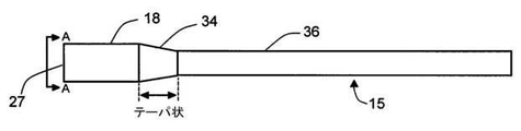
視覚化スタイレットの遠位剛性部分は、2つの異なる直径および長さのセグメント、およびそれらの間のテーパ状移行部34(図3A)という3つの異なる領域を有する。
C. Further Description of the Stiffness Distal Segments of the Visualization Stylet The distal stiffness portions of the visualization stylet consist of two segments of different diameters and lengths, and a tapered transition 34 (FIG. 3A) between them. Has different regions.
(1)遠位の短い長さの拡大された直径の先端部18;デジタル撮像センサのチップと照明ファイバ19の遠位端とを収容する。
(1) A distal short length,
デジタルセンサは、CMOSであっても、ccdタイプのデジタルイメージセンサであってもよい。先に説明した小型の高解像度デジタル撮像構成から、撮像センサ(時にはカメラまたはデジタルカメラチップと呼ばれる)が最大の要素である。視覚化スタイレット7および変更されたヴェレス針12の重大な寸法はまた、図4Aに定義している。先端部の直径14Sodは、主にデジタル撮像センサのサイズによって決定し、次に照明に使用されるファイバ19の直径によって決定する。遠位先端部18は、視覚化スタイレット7の最大のOD部分であり、図4Bのヴェレス針12のガス流シース10の遠位端9を除いていないときに、吹込みガスが通るのを阻止(または大幅に低減)することができる。これは、スタイレットの好ましい特徴である。なぜなら、この幾何学的制限は、ガス流が十分に高く、システムが図4Bに示すような構成にある場合、圧力警報が迅速に生成されて、変更されたヴェレス針のガス流シースの開口部に対するスタイレットの遠位先端部の位置について医師へ迅速にフィードバックを与えることができるからである。遠位先端部18のOD14、つまり14Sodは、ヴェレス針12のガス流シース10のID16、つまり Gidよりもわずかに小さくなるように作られており、そのため、それを依然楽に通れるようになっている(図4Aおよび図4B)。したがって、この実施形態では、次のことが満たされる必要がある:
Sod<Gid。式1
The digital sensor may be a CMOS or a ccd type digital image sensor. From the small high-resolution digital imaging configuration described above, the imaging sensor (sometimes called a camera or digital camera chip) is the largest element. The critical dimensions of the visualization stylet 7 and the modified
S od < Gid . Equation 1
装置のこの実施形態では、ガスが15L/分または好ましくは35L/分で流れるときに、吹込みポンプによって圧力警報が生成されないように、十分な余裕をもつことにより、
SSod<Gid(式2)
となることも必要である。
In this embodiment of the device, by having sufficient margin so that the blow pump does not generate a pressure alarm when the gas flows at 15 L / min or preferably 35 L / min.
SS od < Gid (Equation 2)
It is also necessary to become.
SSod(例えば、図4Aを参照)は、視覚化スタイレット7の剛性の遠位セグメント15の遠位先端部18の部分よりも、長い長さおよび小さな直径の近位部36の外径35である。
The SS od (see, eg, FIG. 4A) has an
より具体的には、式2は、図4に示すように、スタイレット7の近位シャフト36とガス流シャフト10のID16との間に環状空間37が存在することを規定している点に留意されたい。このような環状空間37は、この実施形態によれば、圧力警報を出さないで、少なくとも15L/分、または好ましくは35L/分(スタイレット7の遠位先端部18がヴェレス針12のガス流シース10の遠位先端部9から完全に除去をするとき)のCO2ガスの流れを可能にするほどの大きさでなければならない。必要な隙間は、別の実施形態の図6Aに関連して以下に説明する。
More specifically,
内視鏡検査およびマイクロ撮像の技術に精通している者は、撮像用マイクロ対物レンズ28および照明ファイバ19と共に、ビデオスコープの遠位端がいかに構築されるかを理解することができる。照明ファイバ19の遠位端38は、デジタルセンサ(典型的なビデオスコープ設計)の前に存在する撮像レンズ28システムの遠位面39と同一平面にあることが好ましい。レンズの遠位面39は、好ましくは平らにして、照明ファイバ遠位面38とレンズ遠位面39とを一緒に平坦に研磨することができるように設計することができる(図3B)。図3Bは円柱レンズを示しているが、マイクロ対物レンズ28は矩形または好ましくは正方形の外形を有するようにすることもできる(図3C参照)。このようにして、基礎となる撮像カメラの正方形の典型的な断面プロファイルをより良好に整合させる。次いで、ファイバ19は、レンズの正方形の輪郭の周りに円形構成で配置することができる(図3C)。
Those familiar with endoscopy and microimaging techniques can understand how the distal end of the videoscope is constructed with the
使用されるファイバ19の数およびそれらのサイズは、視覚化スタイレット7のこの拡大させた遠位先端部18の遠位端のOD14がどれほど大きくなり得るかの関数である(ただし、常に式1を満たさなければならない)。好ましくは、照明ファイバ19のサイズおよび数は、撮像レンズ28およびカメラチップセンサ(図3Bでは8本のファイバが例として示されている)に配置されたとき、それらがデジタルカメラチップ(矩形のデジタルセンサの対角線により規定される)によって決定される直径を越えてスタイレットの遠位先端部の断面積を拡大することがないようにするか、それを十分に拡大するが、なお式1を満たすようにしなければならない。式1と同時に式2を満たされなければならないことにも留意されたい。したがって、式2も満たすことができるように、ファイバのサイズの選択を電気コネクタのサイズと共に考慮する必要がある。
The number of
(2)近位のより長い長さ、およびより小さな直径35の金属シャフト36;それは、デジタルセンサからの照明ファイバおよび電気ワイヤーの近位の長さを収容する。
(2) Proximal longer length, and
視覚化スタイレット7のこの部分のOD35、つまり35SSodは、主に照明ファイバのサイズおよび数、およびデジタル撮像センサに取り付けられた導電性アセンブリのODにより決定し、式2を満たすように設計しなければならない。このセグメントは、スタイレット7のシャフトを構成し、このスタイレットは好ましくは図3Aのステンレス鋼で作られている。視覚化スタイレット7の縮小した直径35は、拡大させた先端部18がヴェレス針12のガス流シース10から押し出されたとき、ガスポンプからのいかなる圧力警報をも引き起こすことなく、針により吹込みガスが容易に流れることができるようにする(式2および図4A)。
The OD35, or 35SS od , of this part of the visualization stylet 7 is determined primarily by the size and number of illumination fibers and the OD of the conductive assembly attached to the digital imaging sensor and is designed to satisfy
(3)最後に、テーパ状移行部34;これは、視覚化スタイレット7の剛性部分15の第3の特徴的な幾何学的特徴である。
(3) Finally, the tapered
図3Aの、上記2つの固定された直径の長さの間に存在する領域である。このテーパ状セグメント34は、ステンレス鋼のインサートとして好ましくは形成でき、その近位および遠位の直径は、嵌合する斜視セグメントの直径と良好に整合して、その結果スタイレット7の剛性部分15の外側表面が、その長さ全体に沿って、またテーパ状移行部34全体に沿って、鋭い縁部を有さずに、滑らかになる。テーパ状移行部34の長さ、TaperLは、図3Aに定義されているように、できるだけ短く、好ましくは10倍未満の先端径14である:
TaperL<10*Sod 式3
A region of FIG. 3A that exists between the lengths of the two fixed diameters. The tapered
Taper L <10 * S od formula 3
テーパ状セグメント34はまた、スタイレットの剛性部分の長い長さがより短い直径のセグメントのフレアアウトされたテーパ状のセグメントとして作製できる。また、テーパ状移行領域34を金属インサートで補強することにより、図1Bのヴェレス針12のガス流シース10の変更された平坦な遠位出口縁部が、特に押し出された後(図4A)にガス流チャンバ10に引き戻される(図4B)ときに、スタイレットの外側表面に対して延び、スタイレットから材料を落とすことを防止する。
The tapered
テーパ34が好ましいが、小径から大径への移行は、必要に応じてより急であり得ることを理解すべきである。拡大させた端部が十分に押し出されているとき、鋭い棚部は満足に機能する。簡素な湾曲移行部は、狭いセクション36の遠位端および大きなセクション18の近位端に含まれ得る。
The
D.変更されたヴェレス針への取り付けの説明
スタイレット7を変更されたヴェレス針12の近位ルアーロック入力部40を通るようにするために、このポートからのガス漏れを防ぐシールを施さなければならない。これを、図2の止血Yコネクタ20を使用して達成している。より具体的には、図5のヴェレス針12の近位ルアーロックポート40に止血Yコネクタ20(これはYハブ、20とも呼ばれる場合がある)の回転する雄ルアーロック41を接続することによって行われる。止血弁42を視覚化スタイレット7の近位金属シース36に対して締め付けることによって、ガス流チャンバの密封をYハブ20の近位端41にて行うことができる。このように、図2のヴェレス針12のガス流入シャフト10に対して近位に、ガスの密封が生じている。QOSINA PN 80348という、回転式の雄ルアーロック41および雌ルアーロック43サイドポート44を有する止血弁42のYコネクタなどの市販のYハブ20を使用することができる。QOSINA PN 33057という、片手止血弁Yコネクタ、回転式の雄ルアーロック/雌ルアーロックサイドポートなどの他の類似した製品も同じ機能を果たすことができる。前述のQOSINAという部品と同じ機能性を利用し、その3つのポートに同じ嵌合接続部を有する特注のYハブ20をこの実施形態に使用することもできる。しかし、市販されている部品は安価で使い捨てであり、その機能性について広範に検証されている。
D. Instructions for Attaching to Modified Velez Needle In order for the stylet 7 to pass through the proximal
これらのYハブ20は、中央の内腔を通るものが依然として(止血弁42がどれくらい堅く締め付けられるかに依存して)出入りすることができるように設計されているが、サイドポート44から流れるもの(気体または液体)の重要な密閉を維持することができる(図5)。サイドポート44を通る流れは、図2および図5の矢印45で示される)。Yハブ20の止血弁のネジ42をしっかりと回すと、完全なガスのシールを施しながら、視覚化スタイレット7の位置をヴェレス針12に対しても同様に完全にロックすることができる。Yハブの他の近位ポート(サイドポート44)には、雌ルアーロック43が設けられているので、使用者は吹込みガスポンプから弁ポート56を介して管55を接続することができる(図5)。部品がYハブ20のポートに正しく嵌合できる限り、他の嵌合する接続用雌雄アダプタを利用することもできる。Yハブ20の止血弁42のシール(部分的に締めるにせよ完全に締めるにせよ)により、視覚化スタイレット7による吹き込まれた腹部の長期にわたる視覚での検査が、腹部からのガスの圧力の重大な(またはいかなる)喪失なく、実現できる。なぜなら、ガスポンプは、腹部の圧力を一定に保っている間、圧力警報なく、高い流量でも、スタイレット7の遠位シャフト15の小径剛性部分36(図4Aおよび表1のGidとSSodとの間の環状空間37)の周りのシステムを通ってガスを容易に継続的に流すことができ、システムを介するいかなるガスの損失をも補うことができるからである。
These
最後に、ヴェレス針のもとの吹込みストップコック47の機能が無効にされているので(視覚化スタイレット7が自由に通れるように常に開いた状態にする必要がある)、それは容易に(好ましくは使い捨ての)QOSINA PN 97337などのインラインフロー制御スイッチ56に置き換えることができる。これは図2と図5に示されており、好ましくはYハブ20のサイドポート44に取り付けられ、吹込みポンプ(いかなる図面にも示さず)からのガス流を制御することができる。
Finally, it is easy (it needs to be always open so that the visualization stylet 7 can pass freely) because the function of the
ハードウェアの好ましい使用の説明
変形されたヴェレス針12に対するスタイレット7の好ましい最終配置については、図6を参照されたい。
Description of Preferred Use of Hardware See FIG. 6 for the preferred final placement of the stylet 7 with respect to the modified
(a)わずかに変更されたヴェレス針を通して視覚化スタイレットを挿入する:ヴェレス針12を通して吹込みガスを送るばね作用の鈍い内部カニューレ10が、図1Bに記載されているように変更された後、視覚化スタイレット7は、それを通ることができ、針が腹壁を貫くと、ヴェレス針先端部48が組織を通り、最終的にはそれに対して遠位になることのライブの視認をもたらす。もとのヴェレス針の吹込みストップコック47は常に開いたままである(視覚化スタイレットがガス流シース10を通るので使用しない)。この弁の機能は、Yハブ20のサイドポート44に取り付けられた使い捨ての取り外し可能なインラインフロー制御スイッチ56の追加によって容易に置き換えることができ、つまり図2に示すように、先に説明されている。
(b)組織を貫いている間、視覚化スタイレット7の遠位端27は、ガス流シース10の内部およびその遠位端9の近くに保持され、組織の穿孔および腹膜を通ることを監視する。挿入中に視覚化スタイレットの遠位端27をガス流シース10の遠位端9の少し近位に保つことはまた、穿刺中の組織のデブリおよび血液からの遠位光学部品28の過剰な汚染を防止する。
(c)ヴェレス針12が腹壁および腹膜を通過すると、視覚化スタイレット7が押されて、より大きなOD14遠位先端部18がガス流シース10(図4)の遠位端9を完全に除去することができる。すなわちそれより遠位に押し込まれる。Yハブ20に取り付けられたインラインフロー制御スイッチ56が開き、吹込みを開始することができる。ガス流はまた、視覚化スタイレット7の大きなOD先端部18をガス流シース10(図4B)に戻るようわずかに挿入することによって、使用者が手動で制御することもできる。視覚化スタイレット7の拡大させた遠位先端部18がガス流シース10(図4A)の遠位端9を除くと、スタイレット7のより小さい直径35は、視覚化スタイレット7が貫通器具内にある間に吹込みのため腹部内へガスを正常に流入させ得る。
(d)持ち手31およびそれに付けられたダイアル33の人間工学は、医師が向きを理解し、腹部を視覚化するのを助ける。
(A) Insert the visualization stylet through a slightly modified Veres needle: after the blunt
(B) While penetrating the tissue, the
(C) As the
(D) The ergonomics of the
腹腔を膨張させると、外科医は腔部の内部を見て、サイドポートなどのトロカール用の追加のポート(複数可)のための部位(1つまたは複数)を選択することができる。部位を選択することができ、針の先端部およびスコープは、内部から光線をその部位に向けて組織および皮膚を視覚化するよう狙うことができ、スポットを皮膚にマーキングすることができる。次いで、針を取り外し、その部位を貫通して別のポート(側方ポート)を設けるべく使用する。大型の主トロカール(例えば、10mm)が第1の主ポートに挿入され、内部からの視覚による監視をし、針のビデオスコープを使用して、大型トロカールが適切かつ安全に挿入されるようにする。さらに通常は、必要に応じて小さなトロカールが挿入される。 Inflating the abdominal cavity allows the surgeon to look inside the cavity and select a site (s) for additional ports (s) for trocars, such as side ports. The site can be selected, the tip of the needle and the scope can be aimed from the inside to direct light rays towards the site to visualize the tissue and skin, and spots can be marked on the skin. The needle is then removed and used to penetrate the site and provide another port (side port). A large main trocar (eg, 10 mm) is inserted into the first main port for internal visual monitoring and a needle videoscope to ensure that the large trocar is inserted properly and safely. .. In addition, smaller trocars are usually inserted as needed.
外科処置の終了時に、外科医は、本発明を使用してポートをより良好に閉鎖することができる。小さなポートの1つに針/スコープを使用すると、大型トロカールを内側から見ることができ、除去すると、RFエネルギー(主ポートを通って挿入されたRF器具)を用いて閉鎖を行うことができ、この処置をビデオスクリーンで見る。従来の処置では、大きな中央ポートは典型的にはこのように閉鎖することができず、外側から縫い付けられたのみであった。全部で3つのポートが形成されている場合、スコープを介して(または主ポートを経るより大きいスコープを介して)視覚化し、小さなポートで適用するRFエネルギーを使用して、小さなポートのうちの1つを最初に閉鎖することができる。次に、第3の残りのポートを通る本発明の針/スコープを使用して、腔部内を見ながら、同じ方法で大型トロカールを密封することができる。第3のポートは外部で閉鎖しなければならないが、これは小さなポートであり、このことは簡単に行うことができる。 At the end of the surgical procedure, the surgeon can better close the port using the present invention. Using a needle / scope for one of the smaller ports allows the large trocar to be seen from the inside, and when removed, it can be closed using RF energy (RF instrument inserted through the main port). Watch this procedure on a video screen. With conventional procedures, the large central port typically could not be closed in this way and was only sewn from the outside. If a total of three ports are formed, one of the smaller ports is visualized through a scope (or through a larger scope via the main port) and the RF energy applied at the smaller port is used. One can be closed first. The needle / scope of the invention through the third remaining port can then be used to seal the large trocar in the same way while looking inside the cavity. The third port must be closed externally, which is a small port and this is easy to do.
本発明の他の実施形態
図2の開示された道具および好ましい使用様式を伴うスタイレット7および変更されたヴェレス針12の別の実施形態では、外科医が体腔または器官に選択的に進入することを可能にし得る任意の方法に適用することができる。内視鏡的処置を実行し、それによって外科医は進入中に直接的な視覚化が得られ、組織の分離を視覚化でき、器官と組織の損傷を避けることができる(すなわち、外科医は組織を切開する前に組織を見ることができる)ことを目的として、適用できる。
Other Embodiments of the Invention In another embodiment of the stylet 7 with the disclosed tools and preferred mode of use of FIG. 2 and the modified
視覚化スタイレット7の別の実施形態では、表1に記載されたものより大きな直径のヴェレス針により収容され得る、より大きなカメラを使用できる。この場合、例えば、1.87mm2の断面プロファイルを有するOmnivision CMOSセンサOV06930を使用することができる。より小さいスタイレット構造物について先に開示したものと比較して、適切により大きなマイクロ対物レンズ28も、そのようなセンサと共に使用する必要がある。そのようなより大きなセンサは、以下に示す表に概説しているように、(変更されたヴェレス針12と視覚化スタイレット7の両方について)前述のものと同一であるがより大きな寸法のものとして、同一の機能性の構造体をもたらす。
表2:提案の装置の大型版の実施形態の重要な寸法
In another embodiment of the visualization stylet 7, a larger camera can be used that can be accommodated by a Veres needle with a larger diameter than that listed in Table 1. In this case, for example, Omnivision CMOS sensor OV06930 having a cross-sectional profile of 1.87 mm 2 can be used. Appropriately larger
Table 2: Key dimensions of the large version of the proposed device.
(表1で提案したものより)大きいデジタルカメラを使用するとしても、針の大きさ、17Vodは、腹部を通るように押すための最小サイズの切開を必要とするほど小さい状態を維持していることが好ましい。このようにして、医師に十分な画質(50,000ピクセル超)を提供しながら、(表1で提案したものよりも)わずかに大きな視覚化スタイレット構造物7は、麻酔がほとんどまたはまったくない単純な外来のマイクロ腹腔鏡検査に役立つ。この大型版の実施形態では、17Vodが3.1mmを超えないことが好ましい。 Even with a larger digital camera (than suggested in Table 1), the needle size, 17V od, remains small enough to require a minimum size incision to push through the abdomen. It is preferable to have. In this way, the slightly larger visualization stylet structure 7 (than the one proposed in Table 1) provides little or no anesthesia while providing the physician with sufficient image quality (> 50,000 pixels). Useful for simple outpatient microlaparoscopic examinations. In the embodiment of this large version, it is preferable that 17V od does not exceed 3.1 mm.
別の様式の使用では、使用者は、最初の穿刺および吹込みのために、標準の完全には変更されていないヴェレス針1(図1A)を利用することができる。次いで、この未変更の1針を取り外し、変更された針12を挿入し(図1B)、その後、吹き込みされた腹部のさらなる診断のために視覚化スタイレット7を使用する。または同様に、未変更のヴェレス針1で最初の穿刺が行われ、気腹が達成された後、使用者は、挿入されたヴェレス針1から中間ばね装填インサート2(ガス流管)をゆるめ、腹部を経て針シース4のみを適所に残す。次いで、カスタムのYハブ20(その近位端41に外側針シースの近位端49の雌ねじと噛み合うねじ山が装備されている)を針軸の近位端に素早く接続し、次いでそれを通して視覚化スタイレットを挿入する。先に説明したように、ここから装置の使用を進めることができる。この様式では、ヴェレス針1への変更はまったく必要ではないが、針の最初の挿入は見えずに行われる。吹込みが完了した直後に視覚化スタイレットが挿入される。
In another mode of use, the user can utilize the standard, completely unchanged Verez needle 1 (FIG. 1A) for the initial puncture and infusion. This unmodified needle is then removed and the modified
図6Aは、ヴェレス針(1または12)とほぼ同じOD17であり得、いかなる場合にも、約2.2mmの外径未満(好ましくは、2.0mm以下)の針50が、上述した変更されたヴェレス針12に含まれるような任意のガス流管(2または10)の存在なしに、本発明の視覚化スタイレット52を受ける本発明の変形例を示している。これにより、針50のOD(およびID)は、上記のヴェレス針よりも小さくでき、上記と同じ大きさの視覚化スタイレット52を収容することが可能になり、または内側の摺動可能なガス管10が含まれていないため、視覚化スタイレット52をより大きくすることができる。やはり、挿入針50の内部内腔内の視覚化スタイレット52の狭く細長い剛性セグメント36の間の隙間は、いかなる圧力警報をも作動させることなく、少なくとも15L/分、またはより好ましくは少なくとも35L/分のスタイレットの周りのガス流(図に示すように、拡張される遠位先端部18が伸長したとき)がこの環状空間を通るのを可能にするのに十分である。好ましい実施形態では、これは、第1の実施形態と同様に、1.7mm2よりわずかに大きい隙間の領域によって表される。表1(ヴェレス針のシャフト4およびスタイレット7を説明)から、(π/4)*(1.72−0.82)=1.767mm2。いずれにしても、どちらの実施形態においてもガス流の最小隙間面積は約1mm2、より好ましくは約1.5mm2である。これは、図6Aに示すアセンブリによってより容易に達成されるが、図6Aのアセンブリで必要に応じて針ODを小さくする(またはカメラを大きくする)ことができ、ガス流の所望の隙間を生成することができる。
FIG. 6A can be about the same OD17 as the Velez needle (1 or 12), and in any case the
従来のヴェレス針の場合と同様に、ガスは、弁56によって制御される吹込みガス注入口55から放出され、ガスは、ねじこみ式の止血弁42により逆流が防止されている。これは、図2のようにYハブ20の一部として示されているが、針50と一体であるか継手(図示せず)により針50に取り付けられている新たな設計であってもよい。
As in the case of the conventional Velez needle, the gas is discharged from the
図7に示すさらに別の実施形態では、視覚化スタイレットは、90度の側方視認光学部品および照明で構成することができる。内視鏡の技術に精通している者は、そのようなビデオスコープを構築する方法を理解している。この場合、図1Aの完全には変更されていないヴェレス針1を使用することができる。この実施形態では、スタイレットの遠位の側方視認先端部60は、未変更のヴェレス針1(図7)のガス流シース2のサイドウインドウ6と整列するように移動させている。サイドウインドウ6に対して近位のガス流シース2の側面に、サイドポート孔(図7には図示せず)を穿孔することができる。このようにすると、側方視認スタイレットがガス流管2に挿入されている間に、ガスが流れることができる。この実施形態の欠点は、スタイレットが、針の内部のみから、ヴェレス針のシャフトの中心軸に対して90度の遠位の視認のみを行うことができることである。スタイレットの側方視認方向は矢印61で示されている。
In yet another embodiment shown in FIG. 7, the visualization stylet can consist of 90 degree side visual optics and illumination. Those who are familiar with endoscopic techniques understand how to build such a videoscope. In this case, the Veres needle 1 which has not been completely modified in FIG. 1A can be used. In this embodiment, the distal lateral
別の実施形態では、視覚化スタイレット7の拡大される直径の先端部18は、視覚化スタイレットが図8の貫くヴェレス針の軸を上下に動くときにヴェレス針12からデブリを除去できるようにするために、先端部18の周囲に突出するゴム製のOリング62を有するように適合し得る。この場合式1に反するが、Oリング62は準拠している。Oリングは、ガス流シースID63と接触するのにちょうど十分に突出することができるが、視覚化スタイレットがその内部で前後に押し出されることを可能にする。
In another embodiment, the magnified
さらに別の実施形態では、スタイレットの持ち手31は、図2のように、最終組み立て中に視覚化スタイレット7のシャフト15に永続的には取り付けられないように作製することができる。代わりに、使用中に外科医によってロックおよびロック解除され得る機械的摩擦機構により、持ち手が視覚化スタイレットのシャフト15の周りで自由に回転できるようになる。次いで、外科医は、持ち手のダイアルの向きに対するカメラのポインティングの好ましい向きを見るときに、持ち手をシャフト上にロックすることができる。
In yet another embodiment, the stylet handle 31 can be made to be permanently non-attachable to the
別の実施形態で、スタイレットの遠位端は、ガラスまたはポリマーで作られた保護用の透明の丸みを帯びたカバー64を有することができる。両方の照明光がそれを通り抜けることができるように光学的に透明であるべきで、さらに、先端部に対して遠位の領域の画像をデジタル撮像センサで撮影することができる。このようなカバー64は、レンズおよび照明ファイバの遠位の平らに研磨された光学表面に到達する汚染物質からの保護を提供し、さらに図9の視覚化スタイレットの遠位端に対し鈍い表面を導入する。
In another embodiment, the distal end of the stylet can have a protective transparent
さらに別の実施形態では、変更されたヴェレス針12の図1Bの変更されたガス流シース10は、図10Aの保護用の丸みを帯びたキャップ65を有するように装備することができる。このようにすると、ヴェレス針が最初に腹腔内へと穿刺するとき、丸みを帯びた軟質先端部65は、変更されたヴェレス針12のばね装填内部カニューレ10に取り付けられるため器官のいずれかと接触する可能性がある部分(吹き込み前)である。したがって、この実施形態の軟質の保護用の丸みを帯びた先端部65は、図1Aの未変更のヴェレス針1の鈍い先端部として機能し、同じ機能を果たすことができる。この保護カバー65は、生体吸収性材料で作られていることが好ましい。カバー65は、図10Bの変更されたヴェレス針12(視覚化スタイレット7の遠位先端部18を含む)のガス流シース10を通って嵌合することができる何らかのインサートで押し出されることによって、途中で移動することができる。カバー65が腹腔内に落ちる可能性があり、スタイレットの遠位先端部18がガス流シースに対して遠位に押し込まれ、吹込みが開始でき、カバーが生体吸収性であるので、外科医は体からそれを探したり、除去したりする必要がない。
In yet another embodiment, the modified
スタイレットの別の実施形態では、持ち手31は、光ポート66(図11)を有する。照明ファイバ19が遠位先端部から、視覚化スコープ7の可撓性部分21の近位光コネクタ22まで無処置で続いて外部光源24に接続する(図2のように)代わりに、照明ファイバ19は、図11Aの持ち手66の近位端で終端する。光ガイド67(ファイバまたは液体)は、光源24に接続されて光を伝えており(視覚化スタイレットから完全に独立して)、この場合は図11Aにおいて電気コネクタ23を1つのみ有する。持ち手31の光源24と光ポート66との間に、はるかに大きな直径の光ガイド67を接続することができる。このような光ファイババンドル67は、視覚化スタイレットの照明に使用される小さなファイバ19よりもはるかに光を伝送することができる。照明および光学部品の技術に精通している者は、図11Aの光源およびコネクタが、より大きな光ガイドへの最適な結合のためにいかに構成され得るかを理解する。さらに、標準的な内視鏡的手法は、光ガイドがスコープの近位端の光インターフェイスにいかに接続できるかを示している。
In another embodiment of the stylet, the
異なる実施形態(図11B)では、持ち手31の光ポート66上にLED光源68を直接結合することができる。そのようなLEDは、バッテリ駆動であってもよく、この場合にも、視覚化スタイレットは、電気コネクタを1つだけ有する。
In a different embodiment (FIG. 11B), the
最後に、さらに別の実施形態では、持ち手は無線送信機/受信機69(電池式)を含み、これは今無線送信機/受信機69を含む必要がある画像処理ハードウェア25に電気信号を送信する。この場合、視覚化スタイレットは、近位端から外れるワイヤーを有していない(図11C)。
Finally, in yet another embodiment, the handle comprises a wireless transmitter / receiver 69 (battery-powered), which now has an electrical signal to the
さらに別の実施形態では、持ち手31は、その外面にスイッチを含むこともできる(図11には示していない)。このようなスイッチは、処置中に外科医の手/指によって容易に(見ないでも)アクセス可能である。スイッチは、ビデオ処理ハードウェア25内の記憶装置への画像またはライブビデオの取り込みを開始するために使用することができる。カメラの照明および電子制御のすべての態様を制御するために、複数のノブおよびスイッチを持ち手に取り付けることができる。図11A〜図11Cに示される実施形態の他のいずれかの論理順列も、本出願に含まれる。
In yet another embodiment, the
最後に、システムの別の実施形態では、視覚化スタイレット(図2および図11に示す光源の表現のいずれか)に照明を設けるために使用する光源(24または68)は、狭帯域光観察(NBI)に対応できるようにし得る。そのような光源は市販されており、照明、光学部品、および内視鏡の技術分野において精通している者は、いかにして1つにまとめるかを知っているべきである。そのような照明は、狭帯域光観察(NBI)の最近見出された応用を用いるために使用できる。いくつかの地域で「電子色内視鏡検査」と呼ばれ、この独特な技術は、Gonoが最初に記した(Gono K,et.al.「Appearance of enhanced tissue features in narrow−band endoscopic imaging.」J Biomed Opt.2004;9:568−577)。緑色光および青色光の狭い帯域幅は、ヘモグロビンがこれらの両方の波長に対してピークの吸収スペクトルを有するので、微小血管系のパターンを強調する粘膜の表面の貫通に至る。表面のピットパターンの形態の質も、この技術によって明らかに高められている。このように、この実施形態では、提案の小型の視覚化スタイレットは、腹腔鏡検査中にも同様にNBI内視鏡ツールとしても使用することができる。 Finally, in another embodiment of the system, the light source (24 or 68) used to provide illumination to the visualization stylet (one of the light source representations shown in FIGS. 2 and 11) is narrow band light observation. (NBI) can be made available. Such light sources are commercially available and those familiar with the technical fields of lighting, optics, and endoscopes should know how to combine them into one. Such illumination can be used to take advantage of recently discovered applications of narrow band imaging (NBI). Called "electronic color endoscopy" in some areas, this unique technique was first described by Gono (Gono K, et. Al. "Appearance of enhanced tissues in nurse-band endoscopy." J Biomed Opt. 2004; 9: 568-577). The narrow bandwidth of green and blue light leads to penetration of the mucosal surface, which emphasizes the pattern of the microvasculature, as hemoglobin has a peak absorption spectrum for both of these wavelengths. The quality of the morphology of the surface pit pattern is also clearly enhanced by this technique. Thus, in this embodiment, the proposed small visualization stylet can be used as an NBI endoscopy tool during laparoscopy as well.
本発明の概念は、任意の外科器具に適用でき、器具のサイズおよび吹き込む流体の種類に関わらず、吹込み部位を直接見ながら吹込みができるようにすることであると理解される。 It is understood that the concept of the present invention is applicable to any surgical instrument and allows the infusion to be performed while directly looking at the infusion site, regardless of the size of the instrument and the type of fluid to be infused.
上記の好ましい実施形態は、本発明の原理を説明することを意図しているが、その範囲を限定するものではない。他の実施形態、およびこれらの好ましい実施形態に対する変形形態は、当業者には明らかであり、本発明の精神および範囲から逸脱することなく行うことができる。 The preferred embodiments described above are intended to illustrate the principles of the invention, but do not limit their scope. Other embodiments, and variations to these preferred embodiments, are obvious to those of skill in the art and can be performed without departing from the spirit and scope of the invention.
Claims (16)
中空針の遠位端に穿刺先端部を有し、その中にばね装填吹込み管が配置されている針であって、患者に挿入されて前記気腹術のための腔部を形成するように構成される前記ヴェレス針と、
ガスが前記ヴェレス針によって送達でき、前記針が表面に押し付けられたときに前記ヴェレス針の前記針内腔にばね圧に対して後退することができる、本質的に平坦な遠位端を有する前記吹込み管と、
近位持ち手を有する前記視覚化スタイレットであって、
ここで前記持ち手から伸長する細長いスタイレットシャフトを有し、前記持ち手を使用して前記視覚化スタイレットを位置決めすることによって、前記ヴェレス針の近位端に挿入して前記ヴェレス針の前記遠位端から出るような大きさを有し、前記細長いスタイレットシャフトは、遠位端以外の前記スタイレットシャフトの長さにわたって前記ヴェレス針の内腔の内径よりも顕著により小さな外径を有し、前記スタイレットシャフトの前記ヴェレス針の前記針の内腔を実質的に充填する前記スタイレットシャフトの遠位端は、前記より小さな外径よりもより大きな直径であり、
ここで前記視覚化スタイレットは、小型ビデオスコープであり、前記遠位端の断面積が約1.6mm2以下である遠位端のデジタルビデオカメラ及びレンズのシステムと、前記カメラから前記細長いスタイレットシャフトを通り前記持ち手まで伸長して画像処理および表示装置へ接続する接続ケーブルと、
前記スタイレットシャフトの前記遠位端にある、前記デジタルビデオカメラ及びレンズのシステムにして近接して並んで位置付けられる照明手段と、を含む前記視覚化スタイレットと、
を含み、
前記スタイレットシャフトの前記より小さな外径は前記スタイレットシャフトと前記ヴェレス針の前記内部内腔との間に隙間を残すように、直径が十分に小さく、前記隙間が少なくとも約1mm2の面積を有し、
前記ヴェレス針が前記ヴェレス針の前記遠位端のすぐ内側にある前記視覚化スタイレットの前記遠位端について患者の組織に挿入でき、前記ヴェレス針が組織層を通って前進するときにビデオ画像を提供することにより、前記ヴェレス針について吹込みのための所望の配置に達したら、前記視覚化スタイレットの遠位端を遠位方向に押して、前記ヴェレス針の前記遠位端から前記スタイレットシャフトの前記遠位端を伸長させることができ、そのため前記スタイレットシャフトの前記より大きな直径の端部は前記ヴェレス針の内腔から取り外され、前記ヴェレス針を通って吹込みガスが送達できて、前記患者の気腹術用の腔部が開かれる、組み合わせたもの。 A combination of Velez needles to facilitate pneumoperitoneum and visualization stylets,
A needle having a puncture tip at the distal end of the hollow needle, into which a spring-loaded infusion tube is located, so as to be inserted into the patient to form a cavity for the pneumoperitoneum. The Veres needle, which is composed of
The gas has an essentially flat distal end that can be delivered by the Velez needle and retracts against spring pressure into the needle lumen of the Velez needle when the needle is pressed against a surface. With a blow pipe,
The visualization stylet with a proximal handle,
Here, by having an elongated stylet shaft extending from the handle and using the handle to position the visualization stylet, the Veres needle is inserted into the proximal end of the Velez needle. Large enough to exit the distal end, the elongated stylet shaft has an outer diameter significantly smaller than the inner diameter of the lumen of the Velez needle over the length of the stylet shaft other than the distal end. and, the distal end of the stylet shaft substantially fill the lumen of the needle of the Velez needle of the stylet shaft is larger in diameter than the outer diameter smaller than said,
Here, the visualization stylet is a small videoscope, a system of digital video cameras and lenses at the distal end having a cross-sectional area of about 1.6 mm 2 or less at the distal end , and the elongated style from the camera. A connection cable that extends through the let shaft to the handle and connects to the image processing and display device.
The visualization stylet, including, at the distal end of the stylet shaft, lighting means that are positioned side by side in the system of the digital video camera and lens.
Including
The smaller outer diameter of the stylet shaft is small enough to leave a gap between the stylet shaft and the internal lumen of the Velez needle, with the gap having an area of at least about 1 mm 2. Have and
A video image as the Velez needle can be inserted into the patient's tissue with respect to the distal end of the visualization stylet just inside the distal end of the Velez needle and the Velez needle advances through the panniculus. By providing, when the desired arrangement for blowing on the Velez needle is reached, the distal end of the visualization stylet is pushed distally from the distal end of the Velez needle to the stylet. The distal end of the shaft can be extended so that the larger diameter end of the stylet shaft can be removed from the lumen of the Velez needle and the blown gas can be delivered through the Velez needle. , A combination in which the patient's abdominal cavity is opened.
前記針の前記遠位端に穿刺先端部を有し、前記針の中に内腔を有する中空針であって、前記針の近位に、加圧ガスの供給源に接続するためのポートが設けられて、前記針の前記遠位端を患者に挿入するとき、前記処置を支援する内腔にガスが放出可能な中空針と、
前記針の前記内腔内の視覚化スタイレットであって、
ここで前記視覚化スタイレットは近位持ち手を有し、
ここで前記視覚化スタイレットは前記持ち手から伸長する細長いスタイレットシャフトを有し、前記持ち手を使用して前記視覚化スタイレットを位置決めすることによって、前記針の近位端に挿入して前記針の中の前記内腔の前記遠位端から出るような大きさを有し、前記細長いスタイレットシャフトは、遠位端以外の前記スタイレットシャフトの長さにわたって前記針の中の内腔の内径よりも顕著により小さな外径を有し、前記スタイレットシャフトの前記針の中の前記内腔を実質的に充填する前記スタイレットシャフトの遠位端は、前記より小さな外径よりもより大きな直径であり、
ここで前記視覚化スタイレットは、小型ビデオスコープを含み、前記遠位端にあるデジタルビデオカメラ及びレンズのシステムと、前記カメラから前記細長いスタイレットシャフトを通り前記持ち手まで伸長して画像処理および表示装置へ接続する接続ケーブルとを備え、
前記スタイレットシャフトの前記遠位端にある、前記デジタルビデオカメラ及びレンズのシステムに近接する照明手段と、を含む視覚化スタイレットと、
を含み、
前記スタイレットシャフトの前記より小さな外径は
前記スタイレットシャフトと前記針の中の前記内腔との間に隙間を残すように、直径が十分に小さく、前記隙間が流路を提供するのに十分な面積を有し、
前記針が前記針の前記遠位端のすぐ内側にある前記視覚化スタイレットの前記遠位端について患者の組織に挿入でき、前記針が組織層を通って前進するときにビデオ画像を提供することにより、前記針について吹込みのための所望の配置に達したら、前記視覚化スタイレットの遠位端を前記針に対して遠位方向に押して、前記スタイレットシャフトの前記遠位端を伸長させることができ、そのため前記スタイレットシャフトの前記より大きな直径の端部は前記内腔から十分に取り外され、前記針を通って吹込みガスが送達できる、針およびスコープアセンブリ。 A needle and scope assembly to facilitate laparoscopy and laparoscopy inside the patient's body.
A hollow needle having a puncture tip at the distal end of the needle and a lumen in the needle, with a port proximal to the needle for connecting to a source of pressurized gas. A hollow needle that is provided and is capable of releasing gas into a lumen that assists the procedure when the distal end of the needle is inserted into the patient.
A visualization stylet in the lumen of the needle.
Here the visualization stylet has a proximal handle and
Here, the visualization stylet has an elongated stylet shaft extending from the handle and is inserted into the proximal end of the needle by positioning the visualization stylet using the handle. The elongated stylet shaft has a size that protrudes from the distal end of the lumen in the needle, and the elongated stylet shaft extends the lumen in the needle over the length of the stylet shaft other than the distal end. has a smaller outer diameter markedly than the inner diameter of the distal end of the stylet shaft substantially fill the lumen in the needle of the stylet shaft is more than smaller outer diameter than the It has a large diameter and
Here, the visualization stylet includes a small videoscope, a system of digital video cameras and lenses at the distal end , and image processing and extending from the camera through the elongated stylelet shaft to the handle. Equipped with a connection cable to connect to the display device
A visualization stylet comprising, at the distal end of the stylet shaft, a lighting means in close proximity to the digital video camera and lens system.
Including
The smaller outer diameter of the stylet shaft is small enough to leave a gap between the stylet shaft and the lumen in the needle so that the gap provides a flow path. Has enough area,
The needle can be inserted into the patient's tissue for the distal end of the visualization stylet just inside the distal end of the needle and provides a video image as the needle advances through the panniculus. Thereby, when the desired position for blowing on the needle is reached, the distal end of the visualization stylet is pushed distally to the needle to extend the distal end of the stylet shaft. A needle and scope assembly that allows the stylet shaft to have the larger diameter end sufficiently removed from the cavity and the blown gas to be delivered through the needle.
前記針の遠位端に鋭利な穿刺先端部を有し、前記針の中に内腔を有する中空針であって、前記針は、外部の接手の近位に伸長し、
前記針の中の前記内腔内の視覚化スタイレットであって、
ここで前記視覚化スタイレットは遠位端、及び近位持ち手を有し、
ここで前記視覚化スタイレットは前記持ち手から伸長する細長いスタイレットシャフトを有し、前記スタイレットは前記針の中の前記内腔内で相対的にスライド可能であり、前記ハンドルを使用して前記視覚化スタイレットを位置決めすることにより前記針の前記遠位端を介して外に伸長可能であるように前記針の中の前記内腔に配置されるような大きさを有し、前記細長いスタイレットシャフトは、遠位端以外の前記スタイレットシャフトの長さにわたって前記針の中の内腔の内径よりも顕著により小さな外径を有し、前記スタイレットシャフトの前記内腔を実質的に充填する前記スタイレットシャフトの遠位端は、前記より小さな外径よりもより大きな直径であり、
ここで前記視覚化スタイレットは、小型ビデオスコープを含み、前記遠位端の前記遠位先端部にあるデジタルビデオカメラ及びレンズのシステムと、前記カメラから前記細長いスタイレットシャフトを通り前記持ち手まで伸長して画像処理および表示装置へ接続する接続ケーブルとを備え、
前記スタイレットシャフトの前記遠位先端部にある、前記デジタルビデオカメラ及びレンズのシステムに近接し、並んで位置付けられる照明手段と、を含む視覚化スタイレットと、
を含み、
前記スタイレットシャフトの前記より小さな外径は
前記スタイレットシャフトと、前記スタイレットの前記遠位端が前記内腔の前記端部から遠位方向に外に伸長する際に前記間隙を通る流体の流れのための十分な前記内腔との間に流路のための隙間を残すように、直径が十分に小さいが、前記スタイレットが、前記スタイレットの前記遠位端が前記内腔の中に含まれるように、前記針の中に引かれるときに、流体用の流路を制限し、
前記針が前記針の中の前記内腔の前記遠位端のすぐ内側にある前記視覚化スタイレットの前記遠位端について患者の組織に挿入でき、ビデオ画像を提供し、一度前記針が所望通りに挿入されると、前記視覚化スタイレットは、前記間隙を通して流路を開くために、十分に前記遠位端に伸長するように、前記持ち手を介して、前記針に相対的に遠位置方向に動かされることが可能であり、組織の視覚化、及び前記針を通しての流体の送達が同時に達成される、針およびスコープアセンブリ。 A needle and scope assembly to facilitate an examination of the inside of the patient's body,
A hollow needle having a sharp puncture tip at the distal end of the needle and a lumen in the needle, the needle extending proximal to the outer joint.
A visualization stylet in the lumen of the needle.
Here the visualization stylet has a distal end and a proximal handle.
Here the visualization stylet has an elongated stylet shaft extending from the handle, the stylet being relatively slidable within the lumen within the needle and using the handle. The elongated, having a size such that it is placed in the lumen within the needle so that it can be extended outward through the distal end of the needle by positioning the visualization stylet. stylet shaft has a smaller outer diameter markedly than the inner diameter of the lumen in the needle over the length of the stylet shaft other than the distal end, substantially the lumen of the stylet shaft The distal end of the stylet shaft to be filled has a larger diameter than the smaller outer diameter.
Here, the visualization stylet includes a small videoscope, a system of digital video cameras and lenses at the distal tip of the distal end, and from the camera through the elongated stylet shaft to the handle. Equipped with a connection cable that extends and connects to image processing and display devices,
A visualization stylet comprising, at the distal tip of the stylet shaft, a lighting means located side by side with the digital video camera and lens system.
Including
The smaller outer diameter of the stylet shaft is the fluid that passes through the gap between the stylet shaft and the distal end of the stylet as it extends distally outward from the end of the lumen. The style is small enough to leave a gap for the flow path between it and the lumen sufficient for flow, but the stylet is such that the distal end of the stylet is in the lumen. To limit the flow path for fluids when pulled into the needle, as included in
The needle can be inserted into the patient's tissue for the distal end of the visualization stylet just inside the distal end of the lumen in the needle, providing a video image, once the needle is desired. When inserted in the street, the visualization stylet is relatively far from the needle through the handle so that it extends sufficiently to the distal end to open the flow path through the gap. A needle and scope assembly that can be moved in a positional direction and that simultaneously achieves tissue visualization and delivery of fluid through the needle.
Applications Claiming Priority (4)
| Application Number | Priority Date | Filing Date | Title |
|---|---|---|---|
| US201462076417P | 2014-11-06 | 2014-11-06 | |
| US14/935,325 | 2015-11-06 | ||
| US14/935,325 US10463399B2 (en) | 2014-11-06 | 2015-11-06 | Visually assisted entry of a Veress needle with a tapered videoscope for microlaparoscopy |
| PCT/US2016/060685 WO2017079662A1 (en) | 2014-11-06 | 2016-11-04 | Visually assisted entry of a veress needle with a tapered videoscope for microlaparoscopy |
Publications (3)
| Publication Number | Publication Date |
|---|---|
| JP2018535807A JP2018535807A (en) | 2018-12-06 |
| JP2018535807A5 JP2018535807A5 (en) | 2019-12-19 |
| JP6980670B2 true JP6980670B2 (en) | 2021-12-15 |
Family
ID=57994332
Family Applications (1)
| Application Number | Title | Priority Date | Filing Date |
|---|---|---|---|
| JP2018543277A Active JP6980670B2 (en) | 2014-11-06 | 2016-11-04 | Visual entry support for Velez needles with tapered videoscope for microlaparoscope |
Country Status (9)
| Country | Link |
|---|---|
| US (4) | US10463399B2 (en) |
| EP (1) | EP3370632B1 (en) |
| JP (1) | JP6980670B2 (en) |
| CN (1) | CN108430356B (en) |
| AU (1) | AU2016349495B2 (en) |
| CA (1) | CA3009177C (en) |
| ES (1) | ES2953466T3 (en) |
| HK (1) | HK1256801A1 (en) |
| WO (1) | WO2017079662A1 (en) |
Families Citing this family (25)
| Publication number | Priority date | Publication date | Assignee | Title |
|---|---|---|---|---|
| US20100121139A1 (en) | 2008-11-12 | 2010-05-13 | Ouyang Xiaolong | Minimally Invasive Imaging Systems |
| US11547446B2 (en) | 2014-01-13 | 2023-01-10 | Trice Medical, Inc. | Fully integrated, disposable tissue visualization device |
| US10342579B2 (en) | 2014-01-13 | 2019-07-09 | Trice Medical, Inc. | Fully integrated, disposable tissue visualization device |
| US10105040B2 (en) * | 2015-05-08 | 2018-10-23 | Nanosurgery Technology Corporation | Imaging needle apparatus |
| EP3334322A1 (en) | 2015-08-11 | 2018-06-20 | Trice Medical, Inc. | Fully integrated, disposable tissue visualization device |
| US9829698B2 (en) * | 2015-08-31 | 2017-11-28 | Panasonic Corporation | Endoscope |
| WO2017147605A1 (en) * | 2016-02-26 | 2017-08-31 | Samark Technology Llc | Video needle syringe |
| WO2018064610A1 (en) * | 2016-09-29 | 2018-04-05 | Samark Technology Llc | Video needle syringe |
| WO2018088498A1 (en) * | 2016-11-10 | 2018-05-17 | 京セラオプテック株式会社 | Body cavity observation system, trocar device, and method of operating body cavity observation system |
| KR101889921B1 (en) * | 2016-12-06 | 2018-08-21 | 해성옵틱스(주) | Needle type endoscope |
| US10959756B2 (en) * | 2016-12-15 | 2021-03-30 | Ethicon Llc | Trocar with reduced profile |
| WO2019028458A1 (en) * | 2017-08-04 | 2019-02-07 | Brigham And Women's Hospital, Inc. | Veress-type needles with illuminated guidance and safety features |
| US11382662B2 (en) | 2017-08-04 | 2022-07-12 | The Brigham And Women's Hospital, Inc. | Trocars and veress-type needles with illuminated guidance and safety features |
| JP7056847B2 (en) * | 2017-08-17 | 2022-04-19 | 270 サージカル リミテッド | Multi-camera surgical lighting device with variable diameter |
| CN107468315A (en) * | 2017-09-01 | 2017-12-15 | 张岳农 | A kind of visual pneumoperitoneum puncture needle |
| WO2019191705A1 (en) | 2018-03-29 | 2019-10-03 | Trice Medical, Inc. | Fully integrated endoscope with biopsy capabilities and methods of use |
| CN108392717A (en) * | 2018-04-27 | 2018-08-14 | 武汉佑康科技有限公司 | A kind of visual puncturing movement balloon-system |
| JP7052083B2 (en) * | 2018-12-28 | 2022-04-11 | Hoya株式会社 | Endoscope and endoscopy system |
| US11559646B1 (en) * | 2019-02-11 | 2023-01-24 | Ali Osman | System and method for video assisted percutaneous needle cricothyrotomy and tracheostomy |
| CN110680604A (en) * | 2019-09-18 | 2020-01-14 | 浙江省人民医院 | Optical fiber flute needle |
| WO2022035538A1 (en) * | 2020-08-13 | 2022-02-17 | Arthrex, Inc. | Endoscopic instrument |
| JP2024509487A (en) * | 2021-01-19 | 2024-03-01 | アイ. エイナーソン,ジョン | Trocar and veress-type needles with illuminated guidance and safety features |
| WO2022172192A1 (en) * | 2021-02-12 | 2022-08-18 | Northgate Technologies Inc. | Laparoscopic access device with real-time measurements |
| GR1010162B (en) * | 2021-03-29 | 2022-01-19 | Ιωαννης Κομνηνου Χατζηπαπας | Laparoscopic arrangement applied to laparoscopic operation method |
| CN113598970B (en) * | 2021-08-20 | 2024-02-02 | 重庆市人民医院 | Puncture-preventing cyclic smoke exhaust device and smoke exhaust method for single-port laparoscopic surgery |
Family Cites Families (47)
| Publication number | Priority date | Publication date | Assignee | Title |
|---|---|---|---|---|
| US4816909A (en) | 1986-12-17 | 1989-03-28 | Olympus Optical Co., Ltd. | Video endoscope system for use with different sizes of solid state devices |
| US4869717A (en) * | 1988-04-25 | 1989-09-26 | Adair Edwin Lloyd | Gas insufflation needle with instrument port |
| DE4035146A1 (en) | 1990-11-06 | 1992-05-07 | Riek Siegfried | INSTRUMENT FOR PENETRATING BODY TISSUE |
| US5385572A (en) | 1992-11-12 | 1995-01-31 | Beowulf Holdings | Trocar for endoscopic surgery |
| US5334150A (en) | 1992-11-17 | 1994-08-02 | Kaali Steven G | Visually directed trocar for laparoscopic surgical procedures and method of using same |
| US5751341A (en) | 1993-01-05 | 1998-05-12 | Vista Medical Technologies, Inc. | Stereoscopic endoscope system |
| US5441041A (en) | 1993-09-13 | 1995-08-15 | United States Surgical Corporation | Optical trocar |
| US5720761A (en) | 1993-11-16 | 1998-02-24 | Worldwide Optical Trocar Licensing Corp. | Visually directed trocar and method |
| AU693468B2 (en) * | 1993-11-16 | 1998-07-02 | Ethicon Endo-Surgery, Inc. | Visually directed trocar and method |
| US5609562A (en) * | 1993-11-16 | 1997-03-11 | Worldwide Optical Trocar Licensing Corporation | Visually directed trocar and method |
| US5569291A (en) | 1995-02-01 | 1996-10-29 | Ethicon Endo-Surgery, Inc. | Surgical penetration and dissection instrument |
| GR1002806B (en) | 1996-04-25 | 1997-11-13 | Measurement and relay system of (puncturing) information during laparoscopic and, in general, surgical operations. | |
| US5785644A (en) | 1996-07-12 | 1998-07-28 | Circon Corporation | Pivotal handle assembly for a video operating laparoscope |
| US6656160B1 (en) | 1997-04-29 | 2003-12-02 | Applied Medical Resources Corporation | Insufflation needle apparatus |
| DE19815598B4 (en) | 1998-04-07 | 2007-01-18 | Stm Medizintechnik Starnberg Gmbh | Flexible access tube with everting tube system |
| AU3893299A (en) | 1998-05-13 | 1999-11-29 | Inbae Yoon | Penetrating endoscope and endoscopic surgical instrument with cmos image sensor and display |
| US6527704B1 (en) | 1999-03-10 | 2003-03-04 | Stryker Corporation | Endoscopic camera system integrated with a trocar sleeve |
| US6905489B2 (en) * | 2001-04-24 | 2005-06-14 | Northgate Technologies, Inc. | Laparoscopic insertion device |
| US20030158521A1 (en) | 2002-02-21 | 2003-08-21 | Ameri Darius M. | Trocar placement guide needle |
| US7056329B2 (en) | 2002-10-23 | 2006-06-06 | Intellimed Surgical Solutions, Llc | Laparoscopic direct vision dissecting port |
| US7264847B2 (en) * | 2003-02-19 | 2007-09-04 | Robert P. Bentley, Sr. | Lower alkyl carboxylic acid moieties for preventing oxidative corrosion of metals and organoleptic stabilizer for food and beverages |
| EP3431026B1 (en) | 2004-06-29 | 2020-09-23 | Applied Medical Resources Corporation | Insufflating optical surgical instrument |
| US20060241344A1 (en) | 2005-04-12 | 2006-10-26 | Wilk Patent, Llc | Intra-abdominal surgical method and associated apparatus |
| US7824327B2 (en) | 2005-04-12 | 2010-11-02 | Tyco Healthcare Group Llp | Optical trocar with scope holding assembly |
| US20070123840A1 (en) | 2005-10-18 | 2007-05-31 | Usgi Medical, Inc. | Instrument assisted abdominal access |
| US20070163585A1 (en) * | 2006-01-13 | 2007-07-19 | Olympus Medical Systems Corp. | Method for accessing abdominal cavity and medical procedure via natural orifice |
| US20070260273A1 (en) * | 2006-05-08 | 2007-11-08 | Ethicon Endo-Surgery, Inc. | Endoscopic Translumenal Surgical Systems |
| US7927272B2 (en) * | 2006-08-04 | 2011-04-19 | Avantis Medical Systems, Inc. | Surgical port with embedded imaging device |
| WO2008085918A2 (en) | 2007-01-03 | 2008-07-17 | Tyco Healthcare Group Lp | Access sheath with removable optical penetrating member |
| US20080243162A1 (en) * | 2007-04-02 | 2008-10-02 | Norikiyo Shibata | Trocar |
| US8727969B2 (en) * | 2007-08-06 | 2014-05-20 | Lighthouse Imaging, Llc | Endoscope |
| US20090124927A1 (en) | 2007-11-13 | 2009-05-14 | Chest Innovations, Inc. | Endoscopic system for lung biopsy and biopsy method of insufflating gas to collapse a lung |
| US8548455B2 (en) * | 2009-01-16 | 2013-10-01 | Broadcom Corporation | Method and system for installation and configuration of a femtocell |
| US8523817B2 (en) | 2009-01-23 | 2013-09-03 | Reza S. Mohajer | Veress needle with illuminated guidance and suturing capability |
| US8109943B2 (en) | 2009-04-10 | 2012-02-07 | Gordian Surgical, LLC | Systems and methods for suture anchor deployment |
| US20100274081A1 (en) * | 2009-04-22 | 2010-10-28 | Tyco Healthcare Group Lp | Visual veress needle assembly |
| JP5657673B2 (en) | 2009-09-16 | 2015-01-21 | メディグス リミテッド | Small-diameter video camera head and visualization probe and medical devices incorporating them |
| IN2013MN00105A (en) * | 2010-06-13 | 2015-05-29 | Omeq Medical Ltd | |
| US20110313255A1 (en) | 2010-06-18 | 2011-12-22 | Eric Stanley | Veress needle with removable optical inserts |
| US9522017B2 (en) | 2010-12-03 | 2016-12-20 | Minimally Invasive Devices, Inc. | Devices, systems, and methods for performing endoscopic surgical procedures |
| US20120197078A1 (en) * | 2011-01-31 | 2012-08-02 | Eric Stanley | Insufflation needle with integrated image sensor |
| US8840588B2 (en) | 2011-02-11 | 2014-09-23 | Mectra Labs, Inc. | Insufflation needle with dual indicator and method of use |
| CA2896267A1 (en) * | 2012-12-24 | 2014-07-17 | Novadaq Technologies Inc. | Endoluminal introducer |
| US9693798B2 (en) * | 2013-02-25 | 2017-07-04 | EON Surgical Ltd. | Surgical tool introducer |
| EP2792321B1 (en) | 2013-04-17 | 2017-02-15 | Vesalius Medical Technologies Bvba | A multi-cannula surgical instrument |
| US20160081712A1 (en) | 2013-04-29 | 2016-03-24 | The Charltte-Mecklenburg Hospital Authority D/B/A Carolinas Healthcare System | Device, system, and method for insertion of a medical device into a subject |
| US20140357945A1 (en) | 2013-05-30 | 2014-12-04 | Edward Duckworth | Laparoscopic Trocar with Ventriculoperitoneal Shunt Entry Port |
-
2015
- 2015-11-06 US US14/935,325 patent/US10463399B2/en active Active
-
2016
- 2016-11-04 CN CN201680078260.8A patent/CN108430356B/en active Active
- 2016-11-04 AU AU2016349495A patent/AU2016349495B2/en active Active
- 2016-11-04 ES ES16863107T patent/ES2953466T3/en active Active
- 2016-11-04 EP EP16863107.5A patent/EP3370632B1/en active Active
- 2016-11-04 CA CA3009177A patent/CA3009177C/en active Active
- 2016-11-04 WO PCT/US2016/060685 patent/WO2017079662A1/en active Application Filing
- 2016-11-04 JP JP2018543277A patent/JP6980670B2/en active Active
-
2018
- 2018-12-11 HK HK18115884.7A patent/HK1256801A1/en unknown
-
2019
- 2019-09-18 US US16/574,807 patent/US11284919B1/en active Active
- 2019-11-05 US US16/675,063 patent/US11266442B1/en active Active
-
2022
- 2022-03-04 US US17/687,143 patent/US11602374B1/en active Active
Also Published As
| Publication number | Publication date |
|---|---|
| US11602374B1 (en) | 2023-03-14 |
| JP2018535807A (en) | 2018-12-06 |
| US11266442B1 (en) | 2022-03-08 |
| ES2953466T3 (en) | 2023-11-13 |
| AU2016349495A1 (en) | 2018-06-21 |
| CA3009177C (en) | 2023-01-03 |
| CN108430356B (en) | 2021-02-05 |
| US11284919B1 (en) | 2022-03-29 |
| US10463399B2 (en) | 2019-11-05 |
| EP3370632A1 (en) | 2018-09-12 |
| US20170042573A1 (en) | 2017-02-16 |
| AU2016349495B2 (en) | 2020-07-09 |
| EP3370632B1 (en) | 2023-06-07 |
| EP3370632A4 (en) | 2019-06-05 |
| HK1256801A1 (en) | 2019-10-04 |
| CN108430356A (en) | 2018-08-21 |
| KR20180081550A (en) | 2018-07-16 |
| CA3009177A1 (en) | 2017-05-11 |
| WO2017079662A1 (en) | 2017-05-11 |
Similar Documents
| Publication | Publication Date | Title |
|---|---|---|
| JP6980670B2 (en) | Visual entry support for Velez needles with tapered videoscope for microlaparoscope | |
| US11051851B2 (en) | Veress-type needles with illuminated guidance and safety features | |
| JP4472728B2 (en) | Endoscope system | |
| US6908427B2 (en) | Flexible endoscope capsule | |
| ES2774747T3 (en) | Hysteroscopy and endometrial biopsy apparatus | |
| EP2182833B1 (en) | Endoscope | |
| JP2014509905A (en) | Laparoscopic system | |
| US20120253124A1 (en) | Endoscope air-supply system | |
| JP2023510167A (en) | Injection needle with endoscope for regenerative medicine | |
| JP2008006227A (en) | Laparoscopic port | |
| CN103142289A (en) | Orthopedics curette for use in minimally invasive surgery | |
| US20210330354A1 (en) | Veress-type needles with illuminated guidance and safety features | |
| JP2012085860A (en) | Endoscope and endoscope system | |
| US11065032B2 (en) | Lighting and optics surgical system | |
| KR102664739B1 (en) | Visually assisted invasion of Beres needle with tapered video endoscope for micro-laparoscopy | |
| US9999443B2 (en) | Instrument head single loader | |
| CN220124806U (en) | Endoscope | |
| JP6899316B2 (en) | Lacrimal duct endoscopy | |
| WO2023026118A1 (en) | In-situ scope cleaner |
Legal Events
| Date | Code | Title | Description |
|---|---|---|---|
| A521 | Request for written amendment filed |
Free format text: JAPANESE INTERMEDIATE CODE: A523 Effective date: 20180711 |
|
| A521 | Request for written amendment filed |
Free format text: JAPANESE INTERMEDIATE CODE: A523 Effective date: 20191105 |
|
| A621 | Written request for application examination |
Free format text: JAPANESE INTERMEDIATE CODE: A621 Effective date: 20191105 |
|
| A711 | Notification of change in applicant |
Free format text: JAPANESE INTERMEDIATE CODE: A711 Effective date: 20191212 |
|
| A521 | Request for written amendment filed |
Free format text: JAPANESE INTERMEDIATE CODE: A821 Effective date: 20191212 |
|
| A977 | Report on retrieval |
Free format text: JAPANESE INTERMEDIATE CODE: A971007 Effective date: 20201019 |
|
| A131 | Notification of reasons for refusal |
Free format text: JAPANESE INTERMEDIATE CODE: A131 Effective date: 20201023 |
|
| A521 | Request for written amendment filed |
Free format text: JAPANESE INTERMEDIATE CODE: A523 Effective date: 20201201 |
|
| A131 | Notification of reasons for refusal |
Free format text: JAPANESE INTERMEDIATE CODE: A131 Effective date: 20210415 |
|
| A521 | Request for written amendment filed |
Free format text: JAPANESE INTERMEDIATE CODE: A523 Effective date: 20210715 |
|
| TRDD | Decision of grant or rejection written | ||
| A01 | Written decision to grant a patent or to grant a registration (utility model) |
Free format text: JAPANESE INTERMEDIATE CODE: A01 Effective date: 20211026 |
|
| A61 | First payment of annual fees (during grant procedure) |
Free format text: JAPANESE INTERMEDIATE CODE: A61 Effective date: 20211117 |
|
| R150 | Certificate of patent or registration of utility model |
Ref document number: 6980670 Country of ref document: JP Free format text: JAPANESE INTERMEDIATE CODE: R150 |