JP6979128B2 - Multicopter - Google Patents
Multicopter Download PDFInfo
- Publication number
- JP6979128B2 JP6979128B2 JP2020525300A JP2020525300A JP6979128B2 JP 6979128 B2 JP6979128 B2 JP 6979128B2 JP 2020525300 A JP2020525300 A JP 2020525300A JP 2020525300 A JP2020525300 A JP 2020525300A JP 6979128 B2 JP6979128 B2 JP 6979128B2
- Authority
- JP
- Japan
- Prior art keywords
- lift
- aircraft
- generator
- airframe
- multicopter
- Prior art date
- Legal status (The legal status is an assumption and is not a legal conclusion. Google has not performed a legal analysis and makes no representation as to the accuracy of the status listed.)
- Active
Links
- 230000005484 gravity Effects 0.000 claims description 14
- 230000001133 acceleration Effects 0.000 claims description 13
- RZVHIXYEVGDQDX-UHFFFAOYSA-N 9,10-anthraquinone Chemical compound C1=CC=C2C(=O)C3=CC=CC=C3C(=O)C2=C1 RZVHIXYEVGDQDX-UHFFFAOYSA-N 0.000 claims description 11
- 238000000926 separation method Methods 0.000 claims description 11
- 238000005265 energy consumption Methods 0.000 description 8
- NJPPVKZQTLUDBO-UHFFFAOYSA-N novaluron Chemical compound C1=C(Cl)C(OC(F)(F)C(OC(F)(F)F)F)=CC=C1NC(=O)NC(=O)C1=C(F)C=CC=C1F NJPPVKZQTLUDBO-UHFFFAOYSA-N 0.000 description 5
- 230000007423 decrease Effects 0.000 description 4
- 230000035945 sensitivity Effects 0.000 description 4
- 230000001174 ascending effect Effects 0.000 description 3
- 238000009429 electrical wiring Methods 0.000 description 2
- 239000013585 weight reducing agent Substances 0.000 description 2
- 230000003247 decreasing effect Effects 0.000 description 1
Images


Classifications
-
- B—PERFORMING OPERATIONS; TRANSPORTING
- B64—AIRCRAFT; AVIATION; COSMONAUTICS
- B64C—AEROPLANES; HELICOPTERS
- B64C29/00—Aircraft capable of landing or taking-off vertically, e.g. vertical take-off and landing [VTOL] aircraft
- B64C29/0008—Aircraft capable of landing or taking-off vertically, e.g. vertical take-off and landing [VTOL] aircraft having its flight directional axis horizontal when grounded
- B64C29/0016—Aircraft capable of landing or taking-off vertically, e.g. vertical take-off and landing [VTOL] aircraft having its flight directional axis horizontal when grounded the lift during taking-off being created by free or ducted propellers or by blowers
- B64C29/0025—Aircraft capable of landing or taking-off vertically, e.g. vertical take-off and landing [VTOL] aircraft having its flight directional axis horizontal when grounded the lift during taking-off being created by free or ducted propellers or by blowers the propellers being fixed relative to the fuselage
-
- B—PERFORMING OPERATIONS; TRANSPORTING
- B60—VEHICLES IN GENERAL
- B60L—PROPULSION OF ELECTRICALLY-PROPELLED VEHICLES; SUPPLYING ELECTRIC POWER FOR AUXILIARY EQUIPMENT OF ELECTRICALLY-PROPELLED VEHICLES; ELECTRODYNAMIC BRAKE SYSTEMS FOR VEHICLES IN GENERAL; MAGNETIC SUSPENSION OR LEVITATION FOR VEHICLES; MONITORING OPERATING VARIABLES OF ELECTRICALLY-PROPELLED VEHICLES; ELECTRIC SAFETY DEVICES FOR ELECTRICALLY-PROPELLED VEHICLES
- B60L50/00—Electric propulsion with power supplied within the vehicle
- B60L50/50—Electric propulsion with power supplied within the vehicle using propulsion power supplied by batteries or fuel cells
- B60L50/60—Electric propulsion with power supplied within the vehicle using propulsion power supplied by batteries or fuel cells using power supplied by batteries
-
- B—PERFORMING OPERATIONS; TRANSPORTING
- B64—AIRCRAFT; AVIATION; COSMONAUTICS
- B64D—EQUIPMENT FOR FITTING IN OR TO AIRCRAFT; FLIGHT SUITS; PARACHUTES; ARRANGEMENT OR MOUNTING OF POWER PLANTS OR PROPULSION TRANSMISSIONS IN AIRCRAFT
- B64D27/00—Arrangement or mounting of power plants in aircraft; Aircraft characterised by the type or position of power plants
- B64D27/02—Aircraft characterised by the type or position of power plants
- B64D27/24—Aircraft characterised by the type or position of power plants using steam or spring force
-
- B—PERFORMING OPERATIONS; TRANSPORTING
- B64—AIRCRAFT; AVIATION; COSMONAUTICS
- B64D—EQUIPMENT FOR FITTING IN OR TO AIRCRAFT; FLIGHT SUITS; PARACHUTES; ARRANGEMENT OR MOUNTING OF POWER PLANTS OR PROPULSION TRANSMISSIONS IN AIRCRAFT
- B64D31/00—Power plant control systems; Arrangement of power plant control systems in aircraft
-
- B—PERFORMING OPERATIONS; TRANSPORTING
- B64—AIRCRAFT; AVIATION; COSMONAUTICS
- B64U—UNMANNED AERIAL VEHICLES [UAV]; EQUIPMENT THEREFOR
- B64U30/00—Means for producing lift; Empennages; Arrangements thereof
- B64U30/20—Rotors; Rotor supports
-
- B—PERFORMING OPERATIONS; TRANSPORTING
- B64—AIRCRAFT; AVIATION; COSMONAUTICS
- B64U—UNMANNED AERIAL VEHICLES [UAV]; EQUIPMENT THEREFOR
- B64U30/00—Means for producing lift; Empennages; Arrangements thereof
- B64U30/20—Rotors; Rotor supports
- B64U30/26—Ducted or shrouded rotors
-
- B—PERFORMING OPERATIONS; TRANSPORTING
- B64—AIRCRAFT; AVIATION; COSMONAUTICS
- B64U—UNMANNED AERIAL VEHICLES [UAV]; EQUIPMENT THEREFOR
- B64U50/00—Propulsion; Power supply
- B64U50/10—Propulsion
- B64U50/19—Propulsion using electrically powered motors
-
- B—PERFORMING OPERATIONS; TRANSPORTING
- B60—VEHICLES IN GENERAL
- B60L—PROPULSION OF ELECTRICALLY-PROPELLED VEHICLES; SUPPLYING ELECTRIC POWER FOR AUXILIARY EQUIPMENT OF ELECTRICALLY-PROPELLED VEHICLES; ELECTRODYNAMIC BRAKE SYSTEMS FOR VEHICLES IN GENERAL; MAGNETIC SUSPENSION OR LEVITATION FOR VEHICLES; MONITORING OPERATING VARIABLES OF ELECTRICALLY-PROPELLED VEHICLES; ELECTRIC SAFETY DEVICES FOR ELECTRICALLY-PROPELLED VEHICLES
- B60L2200/00—Type of vehicles
- B60L2200/10—Air crafts
-
- B—PERFORMING OPERATIONS; TRANSPORTING
- B64—AIRCRAFT; AVIATION; COSMONAUTICS
- B64C—AEROPLANES; HELICOPTERS
- B64C13/00—Control systems or transmitting systems for actuating flying-control surfaces, lift-increasing flaps, air brakes, or spoilers
- B64C13/02—Initiating means
- B64C13/04—Initiating means actuated personally
- B64C13/042—Initiating means actuated personally operated by hand
- B64C13/0423—Initiating means actuated personally operated by hand yokes or steering wheels for primary flight controls
-
- B—PERFORMING OPERATIONS; TRANSPORTING
- B64—AIRCRAFT; AVIATION; COSMONAUTICS
- B64D—EQUIPMENT FOR FITTING IN OR TO AIRCRAFT; FLIGHT SUITS; PARACHUTES; ARRANGEMENT OR MOUNTING OF POWER PLANTS OR PROPULSION TRANSMISSIONS IN AIRCRAFT
- B64D31/00—Power plant control systems; Arrangement of power plant control systems in aircraft
- B64D31/02—Initiating means
- B64D31/06—Initiating means actuated automatically
-
- B—PERFORMING OPERATIONS; TRANSPORTING
- B64—AIRCRAFT; AVIATION; COSMONAUTICS
- B64U—UNMANNED AERIAL VEHICLES [UAV]; EQUIPMENT THEREFOR
- B64U2101/00—UAVs specially adapted for particular uses or applications
- B64U2101/30—UAVs specially adapted for particular uses or applications for imaging, photography or videography
-
- Y—GENERAL TAGGING OF NEW TECHNOLOGICAL DEVELOPMENTS; GENERAL TAGGING OF CROSS-SECTIONAL TECHNOLOGIES SPANNING OVER SEVERAL SECTIONS OF THE IPC; TECHNICAL SUBJECTS COVERED BY FORMER USPC CROSS-REFERENCE ART COLLECTIONS [XRACs] AND DIGESTS
- Y02—TECHNOLOGIES OR APPLICATIONS FOR MITIGATION OR ADAPTATION AGAINST CLIMATE CHANGE
- Y02T—CLIMATE CHANGE MITIGATION TECHNOLOGIES RELATED TO TRANSPORTATION
- Y02T10/00—Road transport of goods or passengers
- Y02T10/60—Other road transportation technologies with climate change mitigation effect
- Y02T10/70—Energy storage systems for electromobility, e.g. batteries
-
- Y—GENERAL TAGGING OF NEW TECHNOLOGICAL DEVELOPMENTS; GENERAL TAGGING OF CROSS-SECTIONAL TECHNOLOGIES SPANNING OVER SEVERAL SECTIONS OF THE IPC; TECHNICAL SUBJECTS COVERED BY FORMER USPC CROSS-REFERENCE ART COLLECTIONS [XRACs] AND DIGESTS
- Y02—TECHNOLOGIES OR APPLICATIONS FOR MITIGATION OR ADAPTATION AGAINST CLIMATE CHANGE
- Y02T—CLIMATE CHANGE MITIGATION TECHNOLOGIES RELATED TO TRANSPORTATION
- Y02T50/00—Aeronautics or air transport
- Y02T50/40—Weight reduction
-
- Y—GENERAL TAGGING OF NEW TECHNOLOGICAL DEVELOPMENTS; GENERAL TAGGING OF CROSS-SECTIONAL TECHNOLOGIES SPANNING OVER SEVERAL SECTIONS OF THE IPC; TECHNICAL SUBJECTS COVERED BY FORMER USPC CROSS-REFERENCE ART COLLECTIONS [XRACs] AND DIGESTS
- Y02—TECHNOLOGIES OR APPLICATIONS FOR MITIGATION OR ADAPTATION AGAINST CLIMATE CHANGE
- Y02T—CLIMATE CHANGE MITIGATION TECHNOLOGIES RELATED TO TRANSPORTATION
- Y02T50/00—Aeronautics or air transport
- Y02T50/60—Efficient propulsion technologies, e.g. for aircraft
Landscapes
- Engineering & Computer Science (AREA)
- Aviation & Aerospace Engineering (AREA)
- Mechanical Engineering (AREA)
- Chemical & Material Sciences (AREA)
- Combustion & Propulsion (AREA)
- Life Sciences & Earth Sciences (AREA)
- Sustainable Development (AREA)
- Sustainable Energy (AREA)
- Power Engineering (AREA)
- Transportation (AREA)
- Motorcycle And Bicycle Frame (AREA)
- Arrangement Or Mounting Of Propulsion Units For Vehicles (AREA)
Description
本発明はマルチコプタに関する。 The present invention relates to a multicopter.
マルチコプタとして、乗員座席を有する機体の前後に各々複数の回転翼による揚力発生装置が設けられたもの(例えば、特許文献1)や、同心円上に配置された複数の円環形状の各フレームに複数の揚力発生装置(ロータユニット)が設けられ、中心部に撮影用カメラ等が設けられた胴体部を有するもの(例えば、特許文献2)等が知られている。 As a multicopter, a lift generator with a plurality of rotary wings is provided in front of and behind the aircraft having a passenger seat (for example, Patent Document 1), or a plurality of frames in a plurality of annular shapes arranged on concentric circles. A lift generator (rotor unit) is provided, and a body portion having a body portion provided with a camera for photographing or the like in a central portion (for example, Patent Document 2) is known.
マルチコプタは、飛行のための必要揚力の低減及び飛行時間の拡大のために、換言すると、エネルギ消費量の低減のために、小型化設計が重要な課題である。しかし、特許文献1に示されているようなマルチコプタは、全ての揚力発生装置が機体の横幅内で機体の前後に配置されているので、機体の前後長が長くなり、また、大型の揚力発生装置が用いられると機体の横幅も大きくなり、小型化設計が難しい。 For multicopters, miniaturization design is an important issue for reducing lift required for flight and increasing flight time, in other words, for reducing energy consumption. However, in the multicopter as shown in Patent Document 1, since all the lift generators are arranged in the front and rear of the airframe within the width of the airframe, the front and rear length of the airframe becomes long and a large lift is generated. When the device is used, the width of the airframe also becomes large, making it difficult to design for miniaturization.
マルチコプタの基本的な進行(飛行)方向は前方向であるから、エネルギ消費量の低減のために、前方向への飛行に必要なピッチ方向の姿勢制御がロール方向の姿勢制御に比して効率よく行われ、前後方向の加減速性能がよいことが要求される。しかし、特許文献2に示されているようなマルチコプタは、水平面に対する投影形状に異方性がないため、揚力発生装置の配置に起因するピッチ方向の姿勢制御の感度とロール方向の姿勢制御の感度とが同じになり、ロール方向の姿勢制御に比してピッチ方向の姿勢制御を効率よく行うことができない。しかも、特許文献2に示されているようなマルチコプタは、水平面に対する投影形状に異方性がないため、左右方向への飛行における空気抵抗と基本的な飛方向である前方向への飛行における空気抵抗とが同じなり、エネルギを余分に消費する傾向がある。 Since the basic traveling (flying) direction of the multicopter is the forward direction, the attitude control in the pitch direction required for the forward flight is more efficient than the attitude control in the roll direction in order to reduce energy consumption. It is often done, and it is required that the acceleration / deceleration performance in the front-rear direction is good. However, since the multicopter as shown in Patent Document 2 has no anisotropy in the projected shape with respect to the horizontal plane, the sensitivity of the attitude control in the pitch direction and the sensitivity of the attitude control in the roll direction due to the arrangement of the lift generator Is the same, and the attitude control in the pitch direction cannot be performed more efficiently than the attitude control in the roll direction. Moreover, since the multicopter as shown in Patent Document 2 has no anisotropy in the projected shape with respect to the horizontal plane, the air resistance in the flight in the left-right direction and the air in the flight in the forward direction, which is the basic flight direction. It has the same resistance and tends to consume extra energy.
また、特許文献2に示されているようなマルチコプタは、機体の中心部の周りに複数の揚力発生装置が配置されるから、揚力発生装置が邪魔になって機体中心部に人が近づき難く、乗用のマルチコプタには不向きである。 Further, in the multicopter as shown in Patent Document 2, since a plurality of lift generators are arranged around the center of the machine, the lift generator becomes an obstacle and it is difficult for a person to approach the center of the machine. Not suitable for passenger multicopters.
本発明が解決しようとする課題は、小型化設計の自由度が高く、エネルギ消費量が少ないマルチコプタを提供することである。更には、本発明が解決しようとする課題は、マルチコプタの前後方向の速度性能の向上、前後方向の加減速性能の向上、搭乗性の向上を図ることである。 The problem to be solved by the present invention is to provide a multicopter having a high degree of freedom in miniaturization design and low energy consumption. Further, an object to be solved by the present invention is to improve the speed performance in the front-rear direction of the multicopter, the acceleration / deceleration performance in the front-rear direction, and the boarding property.
本発明の一つの実施形態によるマルチコプタ(10)は、機体(12)と、前記機体(12)の重心を略中心とする第1同心円(C1)上にあって前記機体(12)の前部及び後部に各々左右対称に配置されたN個の第1揚力発生装置(30)と、前記機体(12)の重心(G)を略中心とする前記第1同心円(C1)より大径の第2同心円(C2)上且つ前記機体(12)の前後方向に延在する中心軸線(X)上にあって前記機体(12)の前方及び後方に配置されたM個の第2揚力発生装置(70)とを有する。(但し、N>Mとする。) The multicopter (10) according to one embodiment of the present invention is on a first concentric circle (C1) having a machine body (12) and a center of gravity of the machine body (12) substantially as the center, and is a front portion of the machine body (12). N first lift generators (30) arranged symmetrically at the rear and the first lift generator (30) having a diameter larger than that of the first concentric circle (C1) centered on the center of gravity (G) of the airframe (12). 2 M second lift generators (M) on the concentric circle (C2) and on the central axis (X) extending in the front-rear direction of the airframe (12) and arranged in front of and behind the airframe (12). 70) and. (However, N> M.)
この構成によれば、マルチコプタ(10)の小型化設計の自由度が高く、小型化に伴う軽量化により飛行ためのエネルギ消費量が少なくて済む。また、前方投影面積の減少し、前後方向の速度性能及び前後方向の加速度性能が向上する。 According to this configuration, the degree of freedom in the miniaturization design of the multicopter (10) is high, and the energy consumption for flight can be reduced due to the weight reduction accompanying the miniaturization. In addition, the forward projected area is reduced, and the velocity performance in the front-rear direction and the acceleration performance in the front-rear direction are improved.
上記マルチコプタ(10)において、好ましくは、前部及び後部に配置された前記第1揚力発生装置(30)の前後方向の離間距離及び前記第2揚力発生装置(70)の前後方向の離間距離が、左右に対応するもの同士の前記第1揚力発生装置(30)の左右方向の離間距離より長い。 In the multicopter (10), preferably, the separation distance in the front-rear direction of the first lift generator (30) and the separation distance in the front-rear direction of the second lift generator (70) arranged in the front part and the rear part are set. , The distance between the left and right corresponding devices in the left-right direction is longer than that of the first lift generator (30).
この構成によれば、左右方向(ロール軸)よりも前後方向(ピッチ軸)周りのモーメントが働き易い構造となり、小型軽量化を損なわずに、構造的に簡素に前後左右の異方性、つまり、左右よりも前後に移動し易い異方性が実現し、前後方向の速度性能及び前後方向の加速度性能が向上する。 According to this configuration, the moment in the front-rear direction (pitch axis) is easier to work than in the left-right direction (roll axis), and the anisotropy in the front-back and left-right directions is structurally simple without impairing the miniaturization and weight reduction. , Anisotropy that is easier to move back and forth than left and right is realized, and speed performance in the front-back direction and acceleration performance in the front-back direction are improved.
上記マルチコプタ(10)において、好ましくは、前記第1揚力発生装置(30)及び前記第2揚力発生装置(70)は各々回転翼(34、38、74、78)を含み、前記第2揚力発生装置(70)の回転翼(74、78)の半径が前記第1揚力発生装置(30)の回転翼(34、38)の半径より大きい。 In the multicopter (10), preferably, the first lift generator (30) and the second lift generator (70) include rotary blades (34, 38, 74, 78), respectively, and the second lift generator is generated. The radius of the rotary blade (74, 78) of the device (70) is larger than the radius of the rotary blade (34, 38) of the first lift generator (30).
この構成によれば、前後方向飛行の加減速性能を高めることができる。 According to this configuration, the acceleration / deceleration performance of forward / backward flight can be improved.
上記マルチコプタ(10)において、好ましくは、前記第2揚力発生装置(70)は、隣接する前記第1揚力発生装置(30)に対して、側面視でオーバラップする部分を含む。 In the multicopter (10), preferably, the second lift generator (70) includes a portion that overlaps with the adjacent first lift generator (30) in a side view.
この構成によれば、マルチコプタ(10)の前後長が短縮される。また、第2揚力発生装置(70)間の間隔が大きくなり、機体(12)に対する昇降性が向上する。 According to this configuration, the front-back length of the multicopter (10) is shortened. In addition, the distance between the second lift generators (70) is increased, and the liftability with respect to the airframe (12) is improved.
上記マルチコプタ(10)において、好ましくは、各第1揚力発生装置(30)及び各第2揚力発生装置(70)が、前記機体(12)の互いに異なる2点から各々延出し、且つ各第1揚力発生装置(30)及び各第2揚力発生装置(70)の中心で互いに結合されて平面視でV字形をなすアーム(42、44、82、84)により支持されている。 In the multicopter (10), preferably, each first lift generator (30) and each second lift generator (70) extend from two different points of the airframe (12), and each first. It is supported by arms (42, 44, 82, 84) that are coupled to each other at the center of the lift generator (30) and each second lift generator (70) to form a V-shape in plan view.
この構成によれば、各第1揚力発生装置(30)及び各第2揚力発生装置(70)の支持が1本のアームによる場合に比して構造を複雑にすることなく高い剛性をもって確実に行われる。これにより、構造効率が向上し、軽量化のもとに、前後方向飛行の加減速性能が向上する。 According to this configuration, the support of each first lift generator (30) and each second lift generator (70) is reliably performed with high rigidity without complicating the structure as compared with the case where one arm is used. Will be done. As a result, the structural efficiency is improved, and the acceleration / deceleration performance of the forward / backward flight is improved while the weight is reduced.
上記マルチコプタ(10)において、好ましくは、前記機体(12)は、前後に長い直方体箱状の主部機体(14)と、前記主部機体(14)の前端から前方に延出し、前方に向かうに従って横幅が小さくなり、前部の左右の前記第1揚力発生装置(30)間に突入する前部機体(16)と、前記主部機体(14)の後端から後方に延出し、後方に向かうに従って横幅が小さくなり、後部の左右の前記第1揚力発生装置(30)間に突入する部分を含む後部機体(18)と、前後に長い直方体箱状をなして前記主部機体(14)の左側に設けられ、左右対応する側の前後の前記第1揚力発生装置(30)間に突入する部分を含む左側機体(20)と、前後に長い直方体箱状をなして前記主部機体(14)の右側に設けられ、左右対応する側の前後の前記第1揚力発生装置(30)間に突入する部分を含む右側機体(22)とを有する。 In the multicopter (10), preferably, the airframe (12) has a rectangular box-shaped main airframe (14) long in the front-rear direction, and extends forward from the front end of the main airframe (14) and heads forward. As the width decreases, the front airframe (16) rushes between the left and right first lift generators (30) in the front, and extends rearward from the rear end of the main airframe (14) to the rear. The width becomes smaller toward the rear, and the rear fuselage (18) including the portion that rushes between the left and right first lift generators (30) at the rear and the main fuselage (14) forming a long rectangular box shape in the front-rear direction. The left side machine (20), which is provided on the left side of the above and includes a part that rushes between the front and rear first lift generators (30) on the left and right corresponding sides, and the main body (the main body) that forms a long rectangular box shape in the front and back. It has a right-hand airframe (22) provided on the right side of 14) and including a portion that plunges between the front and rear first lift generators (30) on the left and right corresponding sides.
この構成によれば、マルチコプタ(10)の前後長及び横幅が短縮され、マルチコプタ(10)の小型化が図られる。 According to this configuration, the front-rear length and the width of the multicopter (10) are shortened, and the size of the multicopter (10) can be reduced.
上記マルチコプタ(10)において、好ましくは、前記主部機体(14)の高さが前記左側機体(20)及び前記右側機体(22)の高さより大きく、前記主部機体(14)上に乗員用座席(112)が配置され、前記左側機体(20)及び前記右側機体(22)が昇降時の乗員のステップや前記乗員用座席(112)に着座した乗員のためのフットレストをなす。 In the multicopter (10), preferably, the height of the main body (14) is larger than the heights of the left side machine (20) and the right side machine (22), and the height of the main body (14) is for occupants. A seat (112) is arranged, and the left side aircraft (20) and the right side aircraft (22) form a step for the occupant during ascending / descending and a footrest for the occupant seated in the occupant's seat (112).
この構成によれば、左側機体20及び右側機体22がフットレストとして有効に利用される。
According to this configuration, the
上記マルチコプタ(10)において、好ましくは、前記第1揚力発生装置(30)及び前記第2揚力発生装置(70)は各々回転翼(34、38、74、78)及び前記回転翼(34、38、74、78)を個別に回転駆動する電動機(32、36、72、76)を含み、前記主部機体(14)、前記左側機体(20)及び前記右側機体(22)の各々に前記電動機(32、36、72、76)のための電源バッテリ(130)が収納されている。 In the multicopter (10), preferably, the first lift generator (30) and the second lift generator (70) are rotary blades (34, 38, 74, 78) and rotary blades (34, 38, respectively). , 74, 78), including electric motors (32, 36, 72, 76) that individually rotate and drive, and the electric motors for each of the main body (14), the left side machine (20), and the right side machine (22). A power battery (130) for (32, 36, 72, 76) is housed.
この構成によれば、主部機体(14)、左側機体(20)及び右側機体(22)が各々電源バッテリ(130)の収納ボックスとして有効に利用される。 According to this configuration, the main body (14), the left side machine (20), and the right side machine (22) are each effectively used as a storage box for the power supply battery (130).
上記マルチコプタ(10)において、好ましくは、前記主部機体(14)にジャイロセンサ(120)、加速度センサ(121)及び飛行制御装置(122)のうちの少なくとも一つが設けられ、前記前部機体(16)及び前記後部機体(18)の各々に各電動機(32、36、72、76)の速度制御装置(126)が設けられている。 In the multicopter (10), preferably, at least one of a gyro sensor (120), an acceleration sensor (121) and a flight control device (122) is provided on the main body (14), and the front body (14) is provided. A speed control device (126) for each electric motor (32, 36, 72, 76) is provided in each of the 16) and the rear body (18).
この構成によれば、ジャイロセンサ(120)及び飛行制御装置(122)は機体中央の安全な位置に配置されると共に速度制御装置(126)と各電動機(32、36、72、76)とを接続するケーブルの長さが短くなる。 According to this configuration, the gyro sensor (120) and the flight control device (122) are arranged in a safe position in the center of the fuselage, and the speed control device (126) and each electric motor (32, 36, 72, 76) are connected. The length of the connecting cable is shortened.
本発明によるマルチコプタによれば、小型化設計の自由度が高く、エネルギ消費量が少ない。 According to the multicopter according to the present invention, the degree of freedom in miniaturization design is high and the energy consumption is low.
以下に、本発明によるマルチコプタの実施形態を、図1〜図3を参照して説明する。 Hereinafter, embodiments of the multicopter according to the present invention will be described with reference to FIGS. 1 to 3.
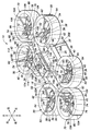
本実施形態によるマルチコプタ10は機体12を有する。機体12は、前後に長い直方形状の箱状の主部機体14と、主部機体14の前端から前方に延出し、前方に向かうに従って横幅が小さくなる切頭四角錘形状の箱状の前部機体16と、主部機体14の後端から後方に延出し、後方に向かうに従って横幅が小さくなる切頭四角錘形状の箱状の後部機体18と、前後に長い直方体箱状をなして主部機体14の左側に連接して設けられた左側機体20と、前後に長い直方体箱状をなして主部機体14の右側に連接して設けられた右側機体22とを有する。
The
前部機体16と後部機体18とは主部機体14の前後方向に延在する中心線に沿って設けられて前後対称の配置である。左側機体20と右側機体22とは、主部機体14の左右両側にあって主部機体14の高さの略1/2の高さを有し、左右対称の配置である。
The
主部機体14、前部機体16、後部機体18、左側機体20及び右側機体22は、各々上方開口の箱本体14A、16A、18A、20A及び22Aと、箱本体14A、16A、18A、20A及び22Aの上部開口を閉じる平板による蓋板14B、16B、18B、20B及び22Bとを含む。
The
機体12の下部には前後方向に長いそり構造の脚体26が取り付けられている。
A
マルチコプタ10は、図2に示されているように、機体12の重心Gを略中心とする半径R1による第1同心円C1上にあって機体12の前部及び後部に各々左右対称に配置された4つの第1揚力発生装置30と、機体12の重心Gを略中心とする第1同心円C1より大径、つまり半径R1により大きい半径R2による第2同心円C2上且つ機体12の前後方向に延在する中心軸線X上にあって機体12の前方及び後方に配置された2つの第2揚力発生装置70とを有する。
As shown in FIG. 2, the
各第1揚力発生装置30は、図1に示されているように、上下2重翼によるもので、下向きの上部電動機32と、上部電動機32の回転軸に取り付けられて上部電動機32によって回転駆動される上部回転翼34と、上部電動機32と同心配置の上向きの下部電動機36と、下部電動機36の回転軸に取り付けられて下部電動機36によって回転駆動される下部回転翼38と、上部回転翼34及び下部回転翼38を取り囲む円環形状の上下開放のファンシュラウド40とを有する。ファンシュラウド40は、電気配線のために、中空構造になっている。
As shown in FIG. 1, each
各第1揚力発生装置30は、機体12の互いに異なる2点から各々延出し、且つ各第1揚力発生装置30の中心で互いに結合されて各々平面視でV字形をなす上部アーム42及び下部アーム44により機体12から支持されている。換言すると、機体12には各第1揚力発生装置30毎の上部アーム42及び下部アーム44によって各第1揚力発生装置30が取り付けられている。
Each of the
詳細には、各上部アーム42は、左側機体20或いは右側機体22の前部外端に取り付けられた中空構造のブラケット46(図2参照)と、ファンシュラウド40の外周を取り巻くように取り付けられてブラケット46を連結されたバンド体48と、上部電動機32の半径方向に延在してバンド体48に連結された一端及び上部電動機32の中心部に連結された中空構造のアーム部材50と、前部機体16の前端の左右の側部或いは後部機体18の後端の左右の側部に取り付けられた中空構造のブラケット52(図2参照)と、バンド体48とは周方向に異なる位置においてファンシュラウド40の外周を取り巻くように取り付けられてブラケット52を連結されたバンド体54と、上部電動機32の半径方向に延在してバンド体54に連結された一端及び上部電動機32の中心部に連結された中空構造のもう一つのアーム部材56とを含む。
Specifically, each
各下部アーム44は、前述のブラケット46及びバンド体48と、下部電動機36の半径方向に延在してバンド体48に連結された一端及び下部電動機36の中心部に連結された中空構造のアーム部材58と、前述のブラケット52及びバンド体54と、下部電動機36の半径方向に延在してバンド体54に連結された一端及び下部電動機36の中心部に連結された中空構造のもう一つのアーム部材60とを含む。
Each
更に、バンド体48、54とは周方向に異なる位置においてファンシュラウド40の外周を取り巻くように取り付けられたバンド体62と、上部電動機32の半径方向に延在してバンド体62に連結された一端及び上部電動機32の中心部に連結されたアーム部材64と、下部電動機36の半径方向に延在してバンド体62に連結された一端及び下部電動機36の中心部に連結されたアーム部材66とが設けられている。
Further, the
各第2揚力発生装置70は、図1に示されているように、上下2重反転翼によるもので、下向きの上部電動機72と、上部電動機72の回転軸に取り付けられて上部電動機72によって回転駆動される上部回転翼74と、上部電動機72と同心配置の上向きの下部電動機76と、下部電動機76の回転軸に取り付けられて下部電動機76によって回転駆動される下部回転翼78と、上部回転翼74及び下部回転翼78を取り囲む円環形状の上下開放のファンシュラウド80とを有する。ファンシュラウド80は、電気配線のために、中空構造になっている。
As shown in FIG. 1, each
各第2揚力発生装置70は、機体12の互いに異なる2点から各々延出し、且つ各第2揚力発生装置70の中心で互いに結合されて各々平面視でV字形をなす上部アーム82及び下部アーム44により機体12から支持されている。換言すると、機体12には各第2揚力発生装置70毎の上部アーム82及び下部アーム84によって各第2揚力発生装置70が取り付けられている。
Each of the
各第1揚力発生装置30は平面視でV字形をなす上部アーム42及び下部アーム44によって、各第2揚力発生装置70は平面視でV字形をなす上部アーム82及び下部アーム84によって機体12に取り付けられていることにより、各第1揚力発生装置30及び各第2揚力発生装置70の支持が1本のアームによる場合に比して構造を複雑にすることなく高い剛性をもって確実に行われる。
Each
詳細には、各上部アーム82は、前部機体16の前端或いは後部機体18の後端に固定された中空構造のブラケット取付部材86の左右両側に各々取り付けられた中空構造のブラケット88、90(図2参照)と、ファンシュラウド80の周方向に異なる2箇所に各々外周の取り巻くように取り付けられてブラケット88、90を連結されたバンド体92、94と、上部電動機72の半径方向に延在してバンド体92、94に連結された一端及び上部電動機72の中心部に連結された中空構造のアーム部材96、98とを含む。
Specifically, each
各下部アーム84は、前述のブラケット88、90及び92、94と、下部電動機76の半径方向に延在してバンド体92、94に連結された一端及び下部電動機76の中心部に連結された中空構造のアーム部材100、102とを含む。
Each
尚、前側のブラケット取付部材86は前部機体16と同様に前方に向かうに従って横幅が小さくなる切頭四角錘形状の箱状に構成され、後側のブラケット取付部材86は後部機体18と同様に後方に向かうに従って横幅が小さくなる切頭四角錘形状の箱状に構成されている。
The
更に、バンド体92、94とは周方向に異なる位置においてファンシュラウド80の外周を取り巻くように取り付けられたバンド体104と、上部電動機72の半径方向に延在してバンド体104に連結された一端及び上部電動機72の中心部に連結されたアーム部材106と、下部電動機76の半径方向に延在してバンド体104に連結された一端及び下部電動機76の中心部に連結されたアーム部材108とが設けられている。
Further, the
上述の各第1揚力発生装置30及び各第2揚力発生装置70の配置により、第1揚力発生装置30のうち機体12の前部及び後部に配置された第1揚力発生装置30の前後方向の離間距離及び第2揚力発生装置70の前後方向の離間距離が、左右に対応するもの同士の第1揚力発生装置30の左右方向の離間距離より長い。
Due to the arrangement of each of the
上述の各第1揚力発生装置30の配置により、前部機体16は前部の左右の第1揚力発生装置30間に突入する部分を含み、後部機体18は後部の左右の第1揚力発生装置30間に突入する部分を含む。これにより、マルチコプタ10の前後長の短縮が図られる。更に、左側機体20は左右対応する側の前後の第1揚力発生装置30間に突入する部分を含み、右側機体22は左右対応する側の前後の第1揚力発生装置30間に突入する部分を含む。これにより、マルチコプタ10の横幅の短縮が図られる。これらのことにより、マルチコプタ10の小型化及び小型化に伴う軽量化が図られ、速度性能及び加速度性能が向上する。
Due to the arrangement of each of the
更に、各第2揚力発生装置70は、隣接する第1揚力発生装置30に対して、側面視でオーバラップする部分を含んでいる。これにより、マルチコプタ10の前後長が短縮される。また、前部の第2揚力発生装置70と後部の第2揚力発生装置70との前後方向の間隔を拡張でき、乗員用座席112に対する昇降性が向上する。
Further, each
前側の2つの第1揚力発生装置30及び1つの第2揚力発生装置70と、後側の2つの第1揚力発生装置30及び1つの第2揚力発生装置70とは、各々平面視でそれら各中心を結ぶ直線が二等辺三角形になり、平面視で所謂俵積み状になるから、デッドスペースが少ない第1揚力発生装置30及び第2揚力発生装置70の配置になる。このことにより、マルチコプタ10の小型化が図られる。
The two
しかも、前側の2つの第1揚力発生装置30及び1つの第2揚力発生装置70は前部機体16の周りを取り囲むように配置され、後側の2つの第1揚力発生装置30と1つの第2揚力発生装置70は後部機体18の周りを取り囲むように配置されているから、各第1揚力発生装置30及び各第2揚力発生装置70の機体12に対する取り付けが、前部機体16或いは後部機体18に近接する態様で、短い支持アーム長をもって確実に行われる。
Moreover, the two
上述の機体12の構成及び各第1揚力発生装置30及び各第2揚力発生装置70の配置により、マルチコプタ10は、最大横幅が最大前後長に比して小さい異方性を有するので、左右方向への飛行における空気抵抗に比して基本的な飛方向である前方向への飛行における空気抵抗が小さくなる。これにより、飛行のためのエネルギ効率が改善され、エネルギ消費量が少なくなる。
Due to the above-mentioned configuration of the
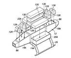
主部機体14上には箱状の座席台110が取り付けられている。座席台110には乗員用座席112が前向きに取り付けられている。座席台110には乗員用座席112の座面は左側機体20及び右側機体22の上面より高い位置にある。これにより、左側機体20及び右側機体22は、乗員用座席112に対する昇降時の乗員のためのステップ及び乗員用座席112に着座した乗員の足置き場であるフットレストをなす。座席台110の前部には乗員用座席112に着座した乗員のための左右のクリップ114を含む固定ハンドル116が取り付けられている。固定ハンドル116を含む乗員用座席112の近傍には飛行操縦装置(不図示)が設けられている。
A box-shaped seat stand 110 is mounted on the
第1揚力発生装置30及び第2揚力発生装置70の群は、機体12の前後に集中しているから、その前後の群の前後方向の中間に位置する乗員用座席112に対する搭乗者の搭乗がし易くなる。
Since the groups of the
主部機体14の箱本体14A内、左側機体20の箱本体20A内及び右側機体22の箱本体22A内は、各上部電動機32、72及び各下部電動機36、76のための電源バッテリをなす長方体形状の複数のバッテリパック130が収納されている。
The inside of the
これにより、主部機体14、左側機体20及び右側機体22が各々バッテリパック130の収納ボックスとして有効に利用される。左側機体20及び右側機体22は、バッテリパック130の収納ボックスと乗員の昇降時のステップ及びフットレストとを兼ねることになり、バッテリ収納ボックスとステップ及びフットレストとを個別に設ける必要がなくなり、部品点数の削減と共にマルチコプタ10の軽量化が図られる。
As a result, the
座席台110は主部機体14の一部をなす。座席台110には、3軸のジャイロセンサ120、3軸の加速度センサ121及び飛行制御装置122及び自律飛行制御装置124が取り付けられている。これにより、ジャイロセンサ120、飛行制御装置122及び自律飛行制御装置124は機体中央の安全な位置に配置される。ジャイロセンサ120は平面視で機体12の重心G或いは重心Gに近い位置に配置されていることが、機体12の姿勢制御上、好ましい。
The
前部機体16の箱本体16A内及び後部機体18の箱本体18A内には、図2に示されているように、各第1揚力発生装置30の上部電動機32、下部電動機36及び各第2揚力発生装置70の上部電動機72、下部電動機76のための複数の速度制御装置126が設けられている。速度制御装置126は各上部電動機32、72及び各下部電動機36、76毎に個別に設けられており、各上部電動機32、72及び各下部電動機36、76の速度制御を個別に行う。
In the
各速度制御装置126と各上部電動機32、72及び各下部電動機36、76との電気的接続は、ファンシュラウド40、80、上部アーム42、82、下部アーム44、84が中空構造であることにより、これらの内部にケーブル(不図示)を通すことにより行われる。各速度制御装置126は各上部電動機32、72及び各下部電動機36、76に近い位置に配置され、速度制御装置126と各上部電動機32、72及び各下部電動機36、76とを接続するケーブル(不図示)の長さが短くなる。
The electrical connection between each
マルチコプタ10は、各上部電動機32、72及び各下部電動機36、76の速度制御が個別に行われることにより、水平姿勢での垂直上昇及び垂直降下と、ピッチ方向の傾斜姿勢による前進・後退飛行と、ロール方向の傾斜姿勢による左右飛行を行うことができる。
The
これらの飛行操縦は、飛行操縦装置(不図示)による以外に、乗員用座席112に着座している乗員の体重移動によって機体12が傾けられることによっても行うことができる。機体12の横幅が抑えられていることにより、機体12をロール方向に傾け易いので、体重移動による操縦性がよくなる。また、ジャイロセンサ120が乗員用座席112に着座している乗員の左右方向の体重移動を検出することにより、左右方向の飛行制御が行われてもよい。
These flight maneuvers can be performed not only by the flight maneuvering device (not shown) but also by tilting the
第1揚力発生装置30のうち機体12の前部及び後部に配置された第1揚力発生装置30の前後方向の離間距離及び第2揚力発生装置70の前後方向の離間距離が、左右に対応するもの同士の第1揚力発生装置30の左右方向の離間距離より長いことにより、ロール方向よりもピッチ方向のモーメントが働き易い構造となり、小型軽量化を損なわずに、構造的に簡素に前後左右の異方性、つまり、左右よりも前後に移動し易い異方性が実現する。これにより、マルチコプタ10の前後方向の速度性能及び前後方向の加速度性能が向上する。
Of the
つまり、各第1揚力発生装置30及び各第2揚力発生装置70の配置に起因するピッチ方向の姿勢制御の感度がロール方向の姿勢制御の感度により高くなり、ロール方向の姿勢制御に比してピッチ方向の姿勢制御が効率よく行われるようになる。これにより、エネルギの無駄な消費が削減され、飛行のためのエネルギ効率が改善され、エネルギ消費量が少なくなる。
That is, the sensitivity of the attitude control in the pitch direction due to the arrangement of each
本発明によるマルチコプタの他の実施形態を、図4を参照して説明する。尚、図4において、図2に対応する部分は、図2に付した符号と同一の符号を付けて、その説明を省略する。 Other embodiments of the multicopter according to the present invention will be described with reference to FIG. In FIG. 4, the portion corresponding to FIG. 2 is designated by the same reference numeral as that shown in FIG. 2, and the description thereof will be omitted.
本実施形態では、第2揚力発生装置70の回転翼74の半径が第1揚力発生装置30の回転翼34の半径より大きい。つまり、第1揚力発生装置30に比して大型の第2揚力発生装置70が用いられる。第2揚力発生装置70の大型化により、第2揚力発生装置70が配置される第2同心円C2は、前述の実施形態のものより大きい半径R3によるものになっている。
In the present embodiment, the radius of the
本実施形態では、第2揚力発生装置70の大型化による出力増大により、前後方向飛行の加速度性能を高めることができる。
In the present embodiment, the acceleration performance of the front-rear flight can be improved by increasing the output by increasing the size of the
以上、本発明を、その好適な実施形態について説明したが、本発明はこのような実施形態により限定されるものではなく、本発明の趣旨を逸脱しない範囲で適宜変更可能である。例えば、主部機体14上に荷物の運搬のために荷台が設けられてもよい。各第1揚力発生装置30及び各第2揚力発生装置70は、反転2重翼によるもの限られることはなく、単翼式のものやその他の揚力発生装置であってもよい。第1揚力発生装置30及び第2揚力発生装置70の個数は、第1揚力発生装置30が4個、第2揚力発生装置70が2個に限られることはなく、第1揚力発生装置30の個数をN個、第2揚力発生装置70の個数をM個とした場合、N>Mであればよい。上記実施形態に示した構成要素は必ずしも全てが必須なものではなく、本発明の趣旨を逸脱しない限りにおいて適宜取捨選択することが可能である。
Although the present invention has been described above with respect to its preferred embodiments, the present invention is not limited to such embodiments and can be appropriately modified without departing from the spirit of the present invention. For example, a loading platform may be provided on the
10 :マルチコプタ
12 :機体
14 :主部機体
14A :箱本体
14B :蓋板
16 :前部機体
16A :箱本体
16B :蓋板
18 :後部機体
18A :箱本体
18B :蓋板
20 :左側機体
20A :箱本体
20B :蓋板
22 :右側機体
22A :箱本体
22B :蓋板
26 :脚体
30 :第1揚力発生装置
32 :上部電動機
34 :上部回転翼
36 :下部電動機
38 :下部回転翼
40 :ファンシュラウド
42 :上部アーム
44 :下部アーム
46 :ブラケット
48 :バンド体
50 :アーム部材
52 :ブラケット
54 :バンド体
56 :アーム部材
58 :アーム部材
60 :アーム部材
62 :バンド体
64 :アーム部材
66 :アーム部材
70 :第2揚力発生装置
72 :上部電動機
74 :上部回転翼
76 :下部電動機
78 :下部回転翼
80 :ファンシュラウド
82 :上部アーム
84 :下部アーム
86 :ブラケット取付部材
88 :ブラケット
90 :ブラケット
92 :バンド体
94 :バンド体
96 :アーム部材
98 :アーム部材
100 :アーム部材
102 :アーム部材
104 :バンド体
106 :アーム部材
108 :アーム部材
110 :座席台
112 :乗員用座席
114 :クリップ
116 :固定ハンドル
120 :ジャイロセンサ
121 :加速度センサ
122 :飛行制御装置
124 :自律飛行制御装置
126 :速度制御装置
130 :バッテリパック(電源バッテリ)10: Multicopter 12: Machine 14: Main body 14A: Box body 14B: Lid plate 16: Front machine 16A: Box body 16B: Lid plate 18: Rear machine 18A: Box body 18B: Lid plate 20: Left side machine 20A: Box body 20B: Lid plate 22: Right side body 22A: Box body 22B: Lid plate 26: Leg body 30: First lift generator 32: Upper motor 34: Upper rotary wing 36: Lower motor 38: Lower rotary wing 40: Fan Shroud 42: Upper arm 44: Lower arm 46: Bracket 48: Band body 50: Arm member 52: Bracket 54: Band body 56: Arm member 58: Arm member 60: Arm member 62: Band body 64: Arm member 66: Arm Member 70: Second lift generator 72: Upper motor 74: Upper rotary wing 76: Lower motor 78: Lower rotary wing 80: Fan shroud 82: Upper arm 84: Lower arm 86: Bracket mounting member 88: Bracket 90: Bracket 92 : Band body 94: Band body 96: Arm member 98: Arm member 100: Arm member 102: Arm member 104: Band body 106: Arm member 108: Arm member 110: Seat stand 112: Passenger seat 114: Clip 116: Fixed Handle 120: Gyro sensor 121: Acceleration sensor 122: Flight control device 124: Autonomous flight control device 126: Speed control device 130: Battery pack (power supply battery)
Claims (12)
前記機体に設けられた揚力発生装置とを有し、
前記揚力発生装置は、前記機体の重心を略中心とする第1同心円上にあって前記機体の前部及び後部に各々左右対称に配置されたN個の第1揚力発生装置及び前記機体の重心を略中心とする前記第1同心円より大径の第2同心円上且つ前記機体の前後方向に延在する中心軸線上にあって前記機体の前方及び後方にのみ配置されたM個の第2揚力発生装置にのみにより構成されているマルチコプタ。(但し、N>Mとする。) With the aircraft
It has a lift generator provided on the airframe and has a lift generator.
The lift generators are N first lift generators and the center of gravity of the airframe, which are symmetrically arranged on the front and rear parts of the airframe on the first concentric circle centered on the center of gravity of the airframe. M second lifts located on the second concentric circle having a diameter larger than that of the first concentric circle and on the central axis extending in the front-rear direction of the aircraft and arranged only in front of and behind the aircraft. A multicopter that is configured solely on the generator. (However, N> M.)
前記機体の重心を略中心とする第1同心円上にあって前記機体の前部及び後部に各々左右対称に配置されたN個の第1揚力発生装置と、
前記機体の重心を略中心とする前記第1同心円より大径の第2同心円上且つ前記機体の前後方向に延在する中心軸線上にあって前記機体の前方及び後方に配置されたM個の第2揚力発生装置とを有し、
前記機体の前部及び後部に配置された前記第1揚力発生装置の前後方向の離間距離及び前記第2揚力発生装置の前後方向の離間距離が、左右に対応するもの同士の前記第1揚力発生装置の左右方向の離間距離より長いマルチコプタ。(但し、N>Mとする。) With the aircraft
N first lift generators arranged symmetrically on the first concentric circle centered on the center of gravity of the airframe and symmetrically on the front and rear parts of the airframe.
M pieces arranged in front of and behind the aircraft on the second concentric circle having a diameter larger than the first concentric circle centered on the center of gravity of the aircraft and on the central axis extending in the front-rear direction of the aircraft. have a second lift force generation device,
The first lift generation device whose front-rear direction separation distance and the front-rear direction separation distance of the first lift generator arranged in the front portion and the rear portion of the machine body correspond to each other on the left and right sides. A multicopter that is longer than the left-right separation distance of the device. (However, N> M.)
前記機体の重心を略中心とする第1同心円上にあって前記機体の前部及び後部に各々左右対称に配置されたN個の第1揚力発生装置と、
前記機体の重心を略中心とする前記第1同心円より大径の第2同心円上且つ前記機体の前後方向に延在する中心軸線上にあって前記機体の前方及び後方に配置されたM個の第2揚力発生装置とを有し、
前記第1揚力発生装置及び前記第2揚力発生装置は各々回転翼を含み、前記第2揚力発生装置の回転翼の半径が前記第1揚力発生装置の回転翼の半径より大きいマルチコプタ。(但し、N>Mとする。) With the aircraft
N first lift generators arranged symmetrically on the first concentric circle centered on the center of gravity of the airframe and symmetrically on the front and rear parts of the airframe.
M pieces arranged in front of and behind the aircraft on the second concentric circle having a diameter larger than the first concentric circle centered on the center of gravity of the aircraft and on the central axis extending in the front-rear direction of the aircraft. have a second lift force generation device,
A multicopter in which the first lift generator and the second lift generator each include a rotary blade, and the radius of the rotary blade of the second lift generator is larger than the radius of the rotary blade of the first lift generator . (However, N> M.)
前記機体の重心を略中心とする第1同心円上にあって前記機体の前部及び後部に各々左右対称に配置されたN個の第1揚力発生装置と、
前記機体の重心を略中心とする前記第1同心円より大径の第2同心円上且つ前記機体の前後方向に延在する中心軸線上にあって前記機体の前方及び後方に配置されたM個の第2揚力発生装置とを有し、
前記機体は、
前後に長い直方体箱状の主部機体と、前記主部機体の前端から前方に延出し、前方に向かうに従って横幅が小さくなり、前部の左右の前記第1揚力発生装置間に突入する前部機体と、
前記主部機体の後端から後方に延出し、後方に向かうに従って横幅が小さくなり、後部の左右の前記第1揚力発生装置間に突入する部分を含む後部機体と、
前後に長い直方体箱状をなして前記主部機体の左側に設けられ、左右対応する側の前後の前記第1揚力発生装置間に突入する部分を含む左側機体と、
前後に長い直方体箱状をなして前記主部機体の右側に設けられ、左右対応する側の前後の前記第1揚力発生装置間に突入する部分を含む右側機体とを有するマルチコプタ。(但し、N>Mとする。) With the aircraft
N first lift generators arranged symmetrically on the first concentric circle centered on the center of gravity of the airframe and symmetrically on the front and rear parts of the airframe.
M pieces arranged in front of and behind the aircraft on the second concentric circle having a diameter larger than the first concentric circle centered on the center of gravity of the aircraft and on the central axis extending in the front-rear direction of the aircraft. have a second lift force generation device,
The aircraft is
A rectangular parallelepiped box-shaped main body that is long in the front-rear direction, and a front part that extends forward from the front end of the main body, narrows in width toward the front, and plunges between the left and right first lift generators in the front part. With the aircraft
A rear fuselage that extends rearward from the rear end of the main fuselage, narrows in width toward the rear, and includes a portion that plunges between the left and right first lift generators in the rear portion.
A left-hand aircraft that is provided on the left side of the main body in the shape of a long rectangular parallelepiped in the front-rear direction and includes a portion that penetrates between the front and rear first lift generators on the left and right corresponding sides.
A multicopter having a rectangular parallelepiped box-shaped long front and rear, provided on the right side of the main body, and having a right side body including a portion that plunges between the front and rear first lift generators on the left and right corresponding sides. (However, N> M.)
前後に長い直方体箱状の主部機体と、前記主部機体の前端から前方に延出し、前方に向かうに従って横幅が小さくなり、前部の左右の前記第1揚力発生装置間に突入する前部機体と、
前記主部機体の後端から後方に延出し、後方に向かうに従って横幅が小さくなり、後部の左右の前記第1揚力発生装置間に突入する部分を含む後部機体と、
前後に長い直方体箱状をなして前記主部機体の左側に設けられ、左右対応する側の前後の前記第1揚力発生装置間に突入する部分を含む左側機体と、
前後に長い直方体箱状をなして前記主部機体の右側に設けられ、左右対応する側の前後の前記第1揚力発生装置間に突入する部分を含む右側機体とを有する請求項1〜3及び5〜8の何れか一項に記載のマルチコプタ。 The aircraft is
A rectangular parallelepiped box-shaped main body that is long in the front-rear direction, and a front part that extends forward from the front end of the main body, narrows in width toward the front, and plunges between the left and right first lift generators in the front part. With the aircraft
A rear fuselage that extends rearward from the rear end of the main fuselage, narrows in width toward the rear, and includes a portion that plunges between the left and right first lift generators in the rear portion.
A left-hand aircraft that is provided on the left side of the main body in the shape of a long rectangular parallelepiped in the front-rear direction and includes a portion that penetrates between the front and rear first lift generators on the left and right corresponding sides.
Provided on a right side of the main portion body forms a long rectangular parallelepiped box-like back and forth claims 1-3 and a right body including a portion projecting into between the front and rear of the first lift force generation device of the left and right side corresponding to and 5. The multicopter according to any one of 5 to 8.
前記主部機体、前記左側機体及び前記右側機体の各々に前記電動機のための電源バッテリが収納されている請求項9に記載のマルチコプタ。 The first lift generator and the second lift generator include a rotary blade and an electric motor for individually rotating and driving the rotary blade, respectively.
The multicopter according to claim 9 , wherein a power supply battery for the electric motor is housed in each of the main body, the left side machine, and the right side machine.
前記前部機体及び前記後部機体の各々に各電動機の速度制御装置が設けられている請求項11に記載のマルチコプタ。 At least one of a gyro sensor, an acceleration sensor and a flight control device is provided on the main body.
The multicopter according to claim 11 , wherein a speed control device for each electric motor is provided in each of the front machine body and the rear machine body.
Applications Claiming Priority (3)
| Application Number | Priority Date | Filing Date | Title |
|---|---|---|---|
| JP2018118540 | 2018-06-22 | ||
| JP2018118540 | 2018-06-22 | ||
| PCT/JP2019/016641 WO2019244462A1 (en) | 2018-06-22 | 2019-04-18 | Multicopter |
Publications (2)
| Publication Number | Publication Date |
|---|---|
| JPWO2019244462A1 JPWO2019244462A1 (en) | 2021-01-07 |
| JP6979128B2 true JP6979128B2 (en) | 2021-12-08 |
Family
ID=68982861
Family Applications (1)
| Application Number | Title | Priority Date | Filing Date |
|---|---|---|---|
| JP2020525300A Active JP6979128B2 (en) | 2018-06-22 | 2019-04-18 | Multicopter |
Country Status (3)
| Country | Link |
|---|---|
| US (1) | US11780571B2 (en) |
| JP (1) | JP6979128B2 (en) |
| WO (1) | WO2019244462A1 (en) |
Families Citing this family (2)
| Publication number | Priority date | Publication date | Assignee | Title |
|---|---|---|---|---|
| US11840329B1 (en) * | 2021-11-08 | 2023-12-12 | Sifly Aviation, Inc. | Contra-rotating electric helicopter |
| EP4310000A1 (en) | 2022-07-19 | 2024-01-24 | AIRBUS HELICOPTERS DEUTSCHLAND GmbH | A rotorcraft with an energy source storage unit |
Family Cites Families (13)
| Publication number | Priority date | Publication date | Assignee | Title |
|---|---|---|---|---|
| JP4223921B2 (en) | 2003-10-24 | 2009-02-12 | トヨタ自動車株式会社 | Vertical take-off and landing flight device |
| US7857253B2 (en) | 2003-10-27 | 2010-12-28 | Urban Aeronautics Ltd. | Ducted fan VTOL vehicles |
| EP1951567A4 (en) * | 2005-11-01 | 2013-04-17 | Urban Aeronautics Ltd | Roof and floor flows |
| US8328130B2 (en) | 2008-12-08 | 2012-12-11 | Honeywell International Inc. | Vertical take off and landing unmanned aerial vehicle airframe structure |
| DE102013104447A1 (en) | 2013-04-30 | 2014-10-30 | Niederberger-Engineering Ag | Automated and flexible self-climbing landing gear with flight characteristics |
| JP2014240242A (en) | 2013-06-12 | 2014-12-25 | 富士重工業株式会社 | Vertical take-off and landing flight vehicle |
| GB2526517A (en) * | 2014-03-27 | 2015-12-02 | Malloy Aeronautics Ltd | Rotor-Lift Aircraft |
| US10427783B2 (en) * | 2015-02-25 | 2019-10-01 | Prodrone Co., Ltd. | Multicopter |
| US10683086B2 (en) * | 2015-03-19 | 2020-06-16 | Prodrone Co., Ltd. | Unmanned rotorcraft and method for measuring circumjacent object around rotorcraft |
| JP6261090B2 (en) * | 2015-05-18 | 2018-01-17 | 株式会社amuse oneself | Unmanned aerial vehicle |
| US20170247107A1 (en) * | 2016-02-29 | 2017-08-31 | GeoScout, Inc. | Rotary-wing vehicle and system |
| US10435176B2 (en) * | 2016-05-25 | 2019-10-08 | Skydio, Inc. | Perimeter structure for unmanned aerial vehicle |
| CN107416194A (en) * | 2017-03-25 | 2017-12-01 | 周良勇 | A kind of multi-rotor unmanned aerial vehicle |
-
2019
- 2019-04-18 WO PCT/JP2019/016641 patent/WO2019244462A1/en active Application Filing
- 2019-04-18 US US17/054,612 patent/US11780571B2/en active Active
- 2019-04-18 JP JP2020525300A patent/JP6979128B2/en active Active
Also Published As
| Publication number | Publication date |
|---|---|
| US20210101675A1 (en) | 2021-04-08 |
| JPWO2019244462A1 (en) | 2021-01-07 |
| WO2019244462A1 (en) | 2019-12-26 |
| US11780571B2 (en) | 2023-10-10 |
Similar Documents
| Publication | Publication Date | Title |
|---|---|---|
| US10710718B2 (en) | Personal flight vehicle | |
| CN207403934U (en) | Multi-rotor unmanned aerial vehicle | |
| JP5920557B2 (en) | Vertical take-off and landing aircraft | |
| JP6979128B2 (en) | Multicopter | |
| KR20170061259A (en) | Multicopter with propelling roter | |
| JPWO2019225607A1 (en) | Aircraft and frame of air vehicle | |
| CN107757897A (en) | Three axle aircraft and mobile takeoff method | |
| JP6993948B2 (en) | Flying device | |
| JP7244084B2 (en) | Electronic parts and aircraft equipped with such electronic parts | |
| EP3959126B1 (en) | Vertical take-off and landing aircraft and related control method | |
| US20180354614A1 (en) | Vertical take-off and landing aircraft | |
| KR101664899B1 (en) | multicopter | |
| US10946705B1 (en) | Flight module for an aerial vehicle | |
| JP2011131861A (en) | Vertical takeoff/landing aircraft | |
| CA2844721A1 (en) | Un aeronef en forme de plateforme capable de transporter un pilote, procedes de fabrication et utilisations associes | |
| JP2023054312A (en) | Air vehicle | |
| US20230202643A1 (en) | Aircraft thrust control system | |
| JP2020108997A (en) | Manned flight vehicle | |
| JP2020066392A (en) | Rotary vane type flight device and attachment for flight device | |
| CN218258694U (en) | Flying body | |
| JP2010042792A (en) | Multifunctional airplane | |
| WO2021070262A1 (en) | Aircraft | |
| JP2020189629A (en) | Flight body | |
| CN116069049A (en) | Five-axis ducted aircraft and control method thereof | |
| JP2020131858A (en) | Flying body |
Legal Events
| Date | Code | Title | Description |
|---|---|---|---|
| A621 | Written request for application examination |
Free format text: JAPANESE INTERMEDIATE CODE: A621 Effective date: 20200728 |
|
| A131 | Notification of reasons for refusal |
Free format text: JAPANESE INTERMEDIATE CODE: A131 Effective date: 20210803 |
|
| A521 | Request for written amendment filed |
Free format text: JAPANESE INTERMEDIATE CODE: A523 Effective date: 20210914 |
|
| TRDD | Decision of grant or rejection written | ||
| A01 | Written decision to grant a patent or to grant a registration (utility model) |
Free format text: JAPANESE INTERMEDIATE CODE: A01 Effective date: 20211102 |
|
| A61 | First payment of annual fees (during grant procedure) |
Free format text: JAPANESE INTERMEDIATE CODE: A61 Effective date: 20211112 |
|
| R150 | Certificate of patent or registration of utility model |
Ref document number: 6979128 Country of ref document: JP Free format text: JAPANESE INTERMEDIATE CODE: R150 |