JP6978951B2 - Dialysis base unit and dialysis system - Google Patents
Dialysis base unit and dialysis system Download PDFInfo
- Publication number
- JP6978951B2 JP6978951B2 JP2018009754A JP2018009754A JP6978951B2 JP 6978951 B2 JP6978951 B2 JP 6978951B2 JP 2018009754 A JP2018009754 A JP 2018009754A JP 2018009754 A JP2018009754 A JP 2018009754A JP 6978951 B2 JP6978951 B2 JP 6978951B2
- Authority
- JP
- Japan
- Prior art keywords
- dialysate
- supply device
- dialysate supply
- dialysis
- base unit
- Prior art date
- Legal status (The legal status is an assumption and is not a legal conclusion. Google has not performed a legal analysis and makes no representation as to the accuracy of the status listed.)
- Active
Links
Images


Classifications
-
- A—HUMAN NECESSITIES
- A61—MEDICAL OR VETERINARY SCIENCE; HYGIENE
- A61M—DEVICES FOR INTRODUCING MEDIA INTO, OR ONTO, THE BODY; DEVICES FOR TRANSDUCING BODY MEDIA OR FOR TAKING MEDIA FROM THE BODY; DEVICES FOR PRODUCING OR ENDING SLEEP OR STUPOR
- A61M1/00—Suction or pumping devices for medical purposes; Devices for carrying-off, for treatment of, or for carrying-over, body-liquids; Drainage systems
- A61M1/14—Dialysis systems; Artificial kidneys; Blood oxygenators ; Reciprocating systems for treatment of body fluids, e.g. single needle systems for hemofiltration or pheresis
- A61M1/16—Dialysis systems; Artificial kidneys; Blood oxygenators ; Reciprocating systems for treatment of body fluids, e.g. single needle systems for hemofiltration or pheresis with membranes
- A61M1/1654—Dialysates therefor
- A61M1/1656—Apparatus for preparing dialysates
-
- A—HUMAN NECESSITIES
- A61—MEDICAL OR VETERINARY SCIENCE; HYGIENE
- A61M—DEVICES FOR INTRODUCING MEDIA INTO, OR ONTO, THE BODY; DEVICES FOR TRANSDUCING BODY MEDIA OR FOR TAKING MEDIA FROM THE BODY; DEVICES FOR PRODUCING OR ENDING SLEEP OR STUPOR
- A61M1/00—Suction or pumping devices for medical purposes; Devices for carrying-off, for treatment of, or for carrying-over, body-liquids; Drainage systems
- A61M1/14—Dialysis systems; Artificial kidneys; Blood oxygenators ; Reciprocating systems for treatment of body fluids, e.g. single needle systems for hemofiltration or pheresis
- A61M1/16—Dialysis systems; Artificial kidneys; Blood oxygenators ; Reciprocating systems for treatment of body fluids, e.g. single needle systems for hemofiltration or pheresis with membranes
- A61M1/1654—Dialysates therefor
- A61M1/1656—Apparatus for preparing dialysates
- A61M1/1657—Apparatus for preparing dialysates with centralised supply of dialysate or constituent thereof for more than one dialysis unit
-
- B—PERFORMING OPERATIONS; TRANSPORTING
- B01—PHYSICAL OR CHEMICAL PROCESSES OR APPARATUS IN GENERAL
- B01D—SEPARATION
- B01D61/00—Processes of separation using semi-permeable membranes, e.g. dialysis, osmosis or ultrafiltration; Apparatus, accessories or auxiliary operations specially adapted therefor
- B01D61/24—Dialysis ; Membrane extraction
- B01D61/32—Controlling or regulating
-
- A—HUMAN NECESSITIES
- A61—MEDICAL OR VETERINARY SCIENCE; HYGIENE
- A61M—DEVICES FOR INTRODUCING MEDIA INTO, OR ONTO, THE BODY; DEVICES FOR TRANSDUCING BODY MEDIA OR FOR TAKING MEDIA FROM THE BODY; DEVICES FOR PRODUCING OR ENDING SLEEP OR STUPOR
- A61M2205/00—General characteristics of the apparatus
- A61M2205/18—General characteristics of the apparatus with alarm
-
- A—HUMAN NECESSITIES
- A61—MEDICAL OR VETERINARY SCIENCE; HYGIENE
- A61M—DEVICES FOR INTRODUCING MEDIA INTO, OR ONTO, THE BODY; DEVICES FOR TRANSDUCING BODY MEDIA OR FOR TAKING MEDIA FROM THE BODY; DEVICES FOR PRODUCING OR ENDING SLEEP OR STUPOR
- A61M2205/00—General characteristics of the apparatus
- A61M2205/27—General characteristics of the apparatus preventing use
- A61M2205/276—General characteristics of the apparatus preventing use preventing unwanted use
-
- A—HUMAN NECESSITIES
- A61—MEDICAL OR VETERINARY SCIENCE; HYGIENE
- A61M—DEVICES FOR INTRODUCING MEDIA INTO, OR ONTO, THE BODY; DEVICES FOR TRANSDUCING BODY MEDIA OR FOR TAKING MEDIA FROM THE BODY; DEVICES FOR PRODUCING OR ENDING SLEEP OR STUPOR
- A61M2205/00—General characteristics of the apparatus
- A61M2205/35—Communication
- A61M2205/3546—Range
- A61M2205/3561—Range local, e.g. within room or hospital
-
- A—HUMAN NECESSITIES
- A61—MEDICAL OR VETERINARY SCIENCE; HYGIENE
- A61M—DEVICES FOR INTRODUCING MEDIA INTO, OR ONTO, THE BODY; DEVICES FOR TRANSDUCING BODY MEDIA OR FOR TAKING MEDIA FROM THE BODY; DEVICES FOR PRODUCING OR ENDING SLEEP OR STUPOR
- A61M2205/00—General characteristics of the apparatus
- A61M2205/35—Communication
- A61M2205/3576—Communication with non implanted data transmission devices, e.g. using external transmitter or receiver
-
- A—HUMAN NECESSITIES
- A61—MEDICAL OR VETERINARY SCIENCE; HYGIENE
- A61M—DEVICES FOR INTRODUCING MEDIA INTO, OR ONTO, THE BODY; DEVICES FOR TRANSDUCING BODY MEDIA OR FOR TAKING MEDIA FROM THE BODY; DEVICES FOR PRODUCING OR ENDING SLEEP OR STUPOR
- A61M2205/00—General characteristics of the apparatus
- A61M2205/58—Means for facilitating use, e.g. by people with impaired vision
- A61M2205/583—Means for facilitating use, e.g. by people with impaired vision by visual feedback
-
- A—HUMAN NECESSITIES
- A61—MEDICAL OR VETERINARY SCIENCE; HYGIENE
- A61M—DEVICES FOR INTRODUCING MEDIA INTO, OR ONTO, THE BODY; DEVICES FOR TRANSDUCING BODY MEDIA OR FOR TAKING MEDIA FROM THE BODY; DEVICES FOR PRODUCING OR ENDING SLEEP OR STUPOR
- A61M2205/00—General characteristics of the apparatus
- A61M2205/60—General characteristics of the apparatus with identification means
- A61M2205/6018—General characteristics of the apparatus with identification means providing set-up signals for the apparatus configuration
Description
本発明は、透析用ベースユニット及び透析システムに関する。 The present invention relates to a dialysis base unit and a dialysis system.
血液透析に用いられる透析システムでは、様々な透析液供給装置が用いられている。透析システムで用いられる透析液供給装置としては、例えば、病院等のCDDS(Central Dialysis fluid Delivery System)に用いられる多人数用透析液供給装置、透析液の原液と水から透析液を調製する機能を有する装置、透析液をバッグ等から供給し使用済みの透析液を再生する機能を有する装置等が知られている。 In the dialysis system used for hemodialysis, various dialysate supply devices are used. Examples of the dialysate supply device used in the dialysis system include a multi-person dialysate supply device used for CDDS (Central Dialysis fluid Delivery System) in hospitals and the like, and a function of preparing a dialysate from undiluted dialysate and water. Devices having a device, a device having a function of supplying a dialysate from a bag or the like and regenerating a used dialysate, and the like are known.
従来、様々な透析液供給装置を用いた透析システムが開発・上市されているが、これら透析システムは各々が異なるコンセプトで製造されており、使用する透析液供給装置に対応した専用の透析システムを使用する必要があった。 Conventionally, dialysis systems using various dialysate supply devices have been developed and put on the market, but each of these dialysis systems is manufactured with a different concept, and a dedicated dialysis system corresponding to the dialysate supply device to be used is available. Had to use.
特許文献1では、可撓性シートの使い捨てユニットを有する透析液カセットと血液カセットを用いた透析システムが開示されている。特許文献1の透析システムによれば、大凡共通したモジュールで様々な透析液供給装置に対応することが可能になる。以下、透析液供給装置と別体に設けられ、透析液供給装置から透析液の供給を受けて血液透析を行う装置を、透析用ベースユニットと呼称する。
ところで、透析用ベースユニットを様々な透析液供給装置に接続可能とした場合、例えば脱気機能がない透析液供給装置が接続された場合に脱気可能なユニットの取付けを示唆するなど、安全上の措置が必要となる場合がある。また、透析液供給装置によって透析用ベースユニット側で制御すべき内容が異なる場合もあり、適切な措置を講じる必要がある。 By the way, when the dialysis base unit can be connected to various dialysate supply devices, for example, when a dialysate supply device having no degassing function is connected, it suggests the installation of a degassable unit for safety reasons. Measures may be required. In addition, the contents to be controlled on the dialysis base unit side may differ depending on the dialysate supply device, and it is necessary to take appropriate measures.
そこで、本発明は、使用する透析液供給装置に応じて適切な措置を講じることが可能な透析用ベースユニット及び透析システムを提供することを目的とする。 Therefore, an object of the present invention is to provide a dialysis base unit and a dialysis system capable of taking appropriate measures according to the dialysate supply device to be used.
本発明は、上記課題を解決することを目的として、透析液供給用の透析液供給装置と別体に設けられ、前記透析液供給装置から透析液の供給を受けて血液透析を行う透析用ベースユニットであって、接続された透析液供給装置を特定可能な透析液供給装置特定手段を備え、前記透析液供給装置特定手段は、前記透析液供給装置が、透析液を調製する液調整部を有し1つの前記透析用ベースユニットに透析液を供給する透析液供給装置か、複数の前記透析用ベースユニットに一括して透析液を供給する多人数用透析液供給装置であるか、使用済みの透析液を再生する透析液再生部を有する透析液供給装置のいずれのタイプであるか特定可能に構成されている、透析用ベースユニットを提供する。 The present invention is provided separately from the dialysate supply device for supplying dialysate for the purpose of solving the above problems, and is a dialysis base for performing dialysis by receiving dialysate from the dialysate supply device. a unit, the connected dialysate supplying device provided with an identifiable dialysate supplying device identifying unit, the dialysate supplying device identifying unit, the dialysate supplying device, the liquid adjusting unit for preparing the dialysis fluid Whether it is a dialysate supply device that supplies dialysate to one dialysis base unit, or a multi-person dialysate supply device that collectively supplies dialysate to multiple dialysis base units, or has been used. Provided is a dialysis base unit configured so as to be able to identify which type of dialysate supply device has a dialysate regenerating unit for regenerating the dialysate.
また、本発明は、上記課題を解決することを目的として、透析液供給用の透析液供給装置と、前記透析用ベースユニットと、を備えた、透析システムを提供する。 Further, the present invention provides a dialysis system including a dialysate supply device for supplying dialysate and a base unit for dialysis, for the purpose of solving the above problems.
本発明によれば、使用する透析液供給装置に応じて適切な措置を講じることが可能な透析用ベースユニット及び透析システムを提供できる。 According to the present invention, it is possible to provide a dialysis base unit and a dialysis system that can take appropriate measures according to the dialysate supply device to be used.
[実施の形態]
以下、本発明の実施の形態を添付図面にしたがって説明する。
[Embodiment]
Hereinafter, embodiments of the present invention will be described with reference to the accompanying drawings.
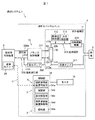
図1は、本実施の形態に係る透析用ベースユニットを用いた透析システムの概略構成図である。透析システム1は、透析液供給用の透析液供給装置2と、本実施の形態に係る透析用ベースユニット3と、を備えている。
FIG. 1 is a schematic configuration diagram of a dialysis system using the dialysis base unit according to the present embodiment. The
(透析液供給装置2)
透析液供給装置2は、透析液を透析用ベースユニット3に供給するための装置である。透析液供給装置2として、例えば、図2(a)に示すように、多数の透析用ベースユニット3に一括して透析液を供給する多人数用透析液供給装置2aが知られている。従来の透析システムでは、多人数用透析液供給装置2aから透析用監視装置と呼称される装置に透析液を供給していたが、本実施の形態では、この透析用監視装置の役割を透析用ベースユニット3が果たすことになる。
(Dialysis fluid supply device 2)
The dialysate supply device 2 is a device for supplying the dialysate to the
他の透析液供給装置2として、図2(b)に示すように、透析液の原液(図示のA原液及びB原液)とRO水から透析液を調製する液調整部21を有する透析液供給装置2bもある。RO水とは、逆浸透膜(RO(Reverse Osmosis)膜)により不純物を除去した水である。なお、図2(b)で示しているものは、2剤の原液(A原液及びB原液)を用いたシステムであるが、必ずしも2剤の原液を用いる必要はなく、例えば1剤の原液、もしくは多数の原液とRO水から透析液を調製してもよい。液調整部21を有する透析液供給装置2bと、透析用ベースユニット3とを合わせて、個人用透析装置と呼称される場合がある。換言すれば、透析用ベースユニット3は、個人用透析装置の一部として用いることもできる。この透析液供給装置2bでは、透析用ベースユニット3から排出された排液を貯留する排液貯留部22も備えられている。ただし、透析用ベースユニット3から直接排液してもよい。
As another dialysate supply device 2, as shown in FIG. 2B, a dialysate supply having a liquid adjusting
さらに他の透析液供給装置2として、図2(c)に示すように、使用済みの透析液を再生する透析液再生部23を有した透析液再生装置2cを用いることもできる。この例では、透析液再生部23は、アンモニアを吸着除去する吸着器23aと、透析液の成分を調整するための注入液を注入する注入部23bと、を有している場合を示しているが、透析液再生部23の具体的な構成は特に限定するものではない。また、透析液再生装置2cは、透析液を貯留するリザーバ24を有している。透析液再生装置2cで用いる透析液は、自身で調製したものであってもよいし、他の透析液供給装置(透析液調製装置)から供給されたものであってもよい。
As still another dialysate supply device 2, as shown in FIG. 2C, a dialysate regeneration device 2c having a
(透析用ベースユニット3)
図1に戻り、透析用ベースユニット3は、透析液供給装置2から透析液の供給を受けて血液透析を行うものである。透析用ベースユニット3は、上述の図2(a)〜(c)で説明したような様々なタイプの透析液供給装置2を接続可能に構成されている。
(Base unit for dialysis 3)
Returning to FIG. 1, the
透析用ベースユニット3は、患者Cの血液を体外循環可能な血液回路310を有する体外循環部31と、血液回路310に設けられた透析器32と、透析液供給装置2から供給された透析液を透析器32に導入し、透析器32から排出された透析液(排液)を透析用ベースユニット3の外部へと排出する透析液回路330を有する透析液送排液部33と、を有している。
The
(透析器32)
透析器32は、ダイアライザとも呼称されるものであり、血液浄化膜(中空糸型の血液透析濾過膜、平膜型の血液透析膜、あるいは血液濾過膜)を内在している。透析器32は、血液を導入する血液導入口32a及び導入した血液を導出する血液導出口32bを有するとともに、透析液を導入する透析液導入口32c及び導入した透析液を排出する透析液排出口32dを有している。透析器32では、血液浄化膜を介して血液と透析液とを接触させることで、血液を浄化する。
(Dialyzer 32)
The
(体外循環部31)
血液回路310は、例えば可撓性を有するチューブ等から構成される。血液回路310は、患者Cの血管から採取した血液を透析器32の血液導入口32aに導く動脈側血液回路310aと、透析器32の血液導出口32bから排出された血液を患者Cに戻す静脈側血液回路310bと、を有している。体外循環部31は、動脈側血液回路310aに配設され、血液を循環させる送液ポンプ311を有している。送液ポンプ311は、例えば、チューブをしごいて血液を透析器32側へと流動させる蠕動型ポンプからなる。
(Extracorporeal circulation part 31)
The blood circuit 310 is composed of, for example, a flexible tube or the like. The blood circuit 310 is an
また、体外循環部31は、静脈側血液回路310bに設けられ、血液回路310を流動する血液の圧力を測定する静脈圧検出器312、及び、血液中の気泡を検出する気泡検出器313を有している。気泡検出器313は、例えば、圧電素子から成る一対の超音波振動素子(発振手段及び受振手段)を有して構成されている。また、静脈側血液回路310bには、気泡検出器313にて気泡が検出されるなどして異常が発生した際に、静脈側血液回路310bを閉塞して血液の体外循環を中断させる流路閉塞機構314が設けられている。静脈圧検出器312及び気泡検出器313は、本発明の異常検知手段を構成するものである。
Further, the
なお、図示していないが、体外循環部31は、血液の抗凝固剤(ヘパリン等)を持続注入する機構や、血液の濃度(ヘマトクリット値)を測定し除水の進行をモニタするヘマトクリットセンサ等をさらに有していてもよい。
Although not shown, the
(透析液送排液部33)
透析液回路330は、例えば可撓性を有するチューブ等から構成される。透析液回路330は、透析液供給装置2から供給された透析液を透析器32の透析液導入口32cに導く導入側透析液回路330aと、透析液排出口32dから排出された透析液を透析液供給装置2へと戻す排出側透析液回路330bと、を有している。
(Dialysis fluid feeding / draining section 33)
The dialysate circuit 330 is composed of, for example, a flexible tube or the like. The dialysate circuit 330 dialysates the introduction
透析液送排液部33は、導入側透析液回路330aと排出側透析液回路330bにわたって設けられ、透析器32への透析液の給液と排液が等量となるように送液を行うバランス制御機構331を有している。バランス制御機構331は、例えば、2つの等量のポンプ室をプランジャが往復動することで給液と排液の等量性を維持する複式ポンプ等からなる。
The dialysate feeding / draining
排出側透析液回路330bには、バランス制御機構331をバイパスするバイパス回路330cが設けられており、このバイパス回路330cに、除水ポンプ332が配設されている。除水ポンプ332を駆動することにより、透析器32への透析液の給液の量よりも排液の量が多くなり、血液からの除水が行われる。
The discharge side dialysate circuit 330b is provided with a
図示していないが、透析液送排液部33は、透析液の温度調節を行う機構や、透析液中の溶存酸素を脱気する機構や、透析液中の微粒子(エンドトキシン)を除去するフィルタや、透析液回路330側への漏血を検出する漏血検出器や、透析器32を通過した後の透析液に紫外線を照射して溶質濃度を測定し、透析効率を求める機構等をさらに有していてもよい。
Although not shown, the dialysate sending / draining
(制御部34)
透析用ベースユニット3は、制御部34を備えている。制御部34は、送液ポンプ311、バランス制御機構331、及び除水ポンプ332の駆動制御を行う。また、制御部34は、静脈圧検出器312や気泡検出器313の検出結果を基に、異常が発生したと判定されたとき、流路閉塞機構314により血液回路310を閉塞すると共に、送液ポンプ311、バランス制御機構331、及び除水ポンプ332の駆動を緊急停止する。制御部34は、CPU等の演算素子、メモリ等の記憶装置、ソフトウェア、インターフェイス等を適宜組み合わせて実現される。
(Control unit 34)
The
本実施の形態では、制御部34は、透析液供給装置特定部34aと、確認部34bと、表示制御部34cと、透析液供給装置制御部34dと、報知部34eと、を有している。以下、各部について詳細に説明する。
In the present embodiment, the
(透析液供給装置特定部34a)
透析液供給装置特定部34aは、本発明の透析液供給装置特定手段4を構成するものであり、透析用ベースユニット3に接続された透析液供給装置2を特定するためのものである。本実施の形態では、透析液供給装置特定手段4は、透析液供給装置特定部34aと信号線41とを有している。透析液供給装置特定部34aは、透析液供給装置2に設けられた通信ユニット25と信号線41を介して有線通信を行うことで、透析液供給装置2を特定するように構成されている。信号線41は、透析用ベースユニット3と透析液供給装置2とが通信を行うための通信手段を構成している。なお、信号線41は透析液回路330と一体となった専用の複合線でもよい。
(Dialysis fluid supply device specific unit 34a)
The dialysate supply device specifying unit 34a constitutes the dialysate supply device specifying means 4 of the present invention, and is for specifying the dialysate supply device 2 connected to the
透析液供給装置特定部34aは、例えば、信号線41を介して、透析液供給装置2を特定するための信号(特定用信号という)を受信する(受信の手段は、透析液供給装置特定部34aから要求してもよいし、通信ユニットから特定用信号を送信しても良い)。透析液供給装置特定部34aは、受信した特定用信号を基に、予め記憶させておいたデータベースを参照するなどして、透析液供給装置2のタイプ(例えば、図2(a)〜(c)のいずれのタイプに相当するか)や機種を特定する。 The dialysate supply device specifying unit 34a receives, for example, a signal (referred to as a specifying signal) for specifying the dialysate supply device 2 via the signal line 41 (the receiving means is the dialysate supply device specifying unit). It may be requested from 34a, or a specific signal may be transmitted from the communication unit). The dialysate supply device specifying unit 34a refers to a database stored in advance based on the received identification signal, and the type of the dialysate supply device 2 (for example, FIGS. 2A to 2C). ) Which type corresponds to) and the model.
透析液供給装置特定部34aは、例えば、脱気機能がない透析液供給装置2が接続されている場合には、表示制御部34cを介して後述するモニタ35に脱気可能なユニットの取付けを示唆する表示を行うなど、安全上の措置を促すように構成されていてもよい。
For example, when the dialysate supply device 2 having no degassing function is connected to the dialysate supply device specifying unit 34a, a unit capable of degassing is attached to the
(透析液供給装置特定手段4の変形例)
なお、ここでは有線通信により透析液供給装置特定部34aと通信ユニット25間の通信を行ったが、これに限らず、透析液供給装置特定部34aと通信ユニット25間の通信を無線通信により行ってもよい。無線通信の方式としては、Bluetooth(登録商標)等が挙げられる。透析液供給装置特定部34aと通信ユニット25間の通信を無線通信により行うことで、透析用ベースユニット3から離れた位置に透析液供給装置2が配置されている場合であっても、透析液供給装置2の特定を容易に行うことが可能になる。
(Variation example of dialysate supply device specifying means 4)
Here, the communication between the dialysate supply device specifying unit 34a and the
また、透析用ベースユニット3の近傍に透析液供給装置2が配置される場合には、透析液供給装置特定部34aと通信ユニット25間でRFID(Radio Frequency IDentifier)等のICタグを用いた近距離無線通信により、特定用信号を送受信するように透析液供給装置特定手段4を構成してもよい。この場合、透析液供給装置2には、通信ユニット25に代えて、RFタグ等のICタグが搭載されることになる。
When the dialysate supply device 2 is arranged in the vicinity of the
さらに、図3に示すように、透析液供給装置2に信号線41を接続するコネクタ42に複数のスイッチ42aを形成すると共に、コネクタ42が嵌合される透析液供給装置2のレセプタクル43に、透析液供給装置2のタイプや機種に応じた特定のスイッチ42aを押し込む突起43aを設け、どのスイッチ42aが押し込まれるかを検知することで、透析液供給装置2の特定を行うように透析液供給装置特定手段4を構成してもよい。なお、図3の例はあくまで一例であり、スイッチ42aの形状等は図示のものに限定されない。
Further, as shown in FIG. 3, a plurality of
さらにまた、透析液回路330に透析液の圧力を測定する圧力センサや、透析液の濃度を測定する濃度センサを設け、透析液供給装置2に透析液の吐出圧や濃度を変更する信号を出力した際に圧力や濃度が変化するか否かを透析液供給装置特定部34aで検出することで、透析液供給装置2の特定を行うように透析液供給装置特定手段4を構成してもよい。 Furthermore, a pressure sensor for measuring the pressure of the dialysate and a concentration sensor for measuring the concentration of the dialysate are provided in the dialysate circuit 330, and a signal for changing the discharge pressure and the concentration of the dialysate is output to the dialysate supply device 2. The dialysate supply device specifying means 4 may be configured so as to specify the dialysate supply device 2 by detecting whether or not the pressure or the concentration changes at the same time by the dialysate supply device specifying unit 34a. ..
また、透析用ベースユニット3に入力手段を設け、入力手段によって透析液供給装置2の機種やタイプを入力するように透析液供給装置特定手段4を構成してもよい。入力手段としては、例えば、後述するモニタ35に表示された機種等の選択肢を参照して機種等を選択する、あるいは機種毎に設定されたボタンを押すなどの手入力方式の入力装置としてもよい。手入力方式の入力装置を用いる場合、透析液供給装置2を特定するためのセンサ等が不要になるため、透析システム1のシステム構成を簡単化でき、コストも抑えることが可能になる。
Further, the
入力手段は、手入力方式のものに限らず、透析液供給装置2に付された機種識別用のバーコードを読み込むバーコードリーダであってもよいし、カメラ等の撮像装置であってもよい。入力手段としてカメラ等の撮像装置を用いる場合、撮像した透析液供給装置2の画像(例えば色や形)を基に透析液供給装置2の機種等を判別するように透析液供給装置特定部34aを構成すればよい。 The input means is not limited to the manual input method, and may be a bar code reader for reading a model identification bar code attached to the dialysate supply device 2, or an image pickup device such as a camera. .. When an image pickup device such as a camera is used as the input means, the dialysate supply device specifying unit 34a so as to determine the model of the dialysate supply device 2 based on the image (for example, color and shape) of the dialysate supply device 2 captured. Should be configured.
(確認部34b)
図1に戻り、確認部34bは、本発明の確認手段5を構成するものであり、透析液供給装置特定手段4で特定された透析液供給装置2が正しいか否かを確認する(つまり再検証する)ものである。確認手段5としては、上述の透析液供給装置特定手段4と同様のものを用いることができる。つまり、透析用ベースユニット3に、透析液供給装置2を特定する手段を2つ以上設け、一方を透析液供給装置特定手段4として用い、他方を確認手段5として用いることができる。また、確認部34bは、例えば透析液の濃度調整を行うことが可能な透析液供給装置2が接続されていると透析液供給装置特定手段4で特定された場合には、透析液の濃度調整を変更する制御を行い、実際に透析液の濃度が変化していることを確認するなど、特定された透析液供給装置2に応じて確認方法を異ならせるものであってもよい。
(
Returning to FIG. 1, the
確認部34bは、透析液供給装置特定手段4で特定した透析液供給装置2が正しくない場合、表示制御部34cを介してモニタ35に警告を表示するなど、安全を確保するための動作を行うように構成されていてもよい。なお、確認手段5を設けることは必須ではないが、特に透析液供給装置特定手段4として手入力方式の入力装置を用いる場合には、入力を間違えてしまう可能性があるため、確認手段を設けることが望ましい。
If the dialysate supply device 2 specified by the dialysate supply device specifying means 4 is incorrect, the
(表示制御部34c)
本実施の形態では、透析用ベースユニット3に、透析状況あるいは設定可能な透析条件等を表示するモニタ35が設けられている。表示制御部34cは、透析液供給装置特定手段4で特定された透析液供給装置2に応じて、モニタ35の表示内容を変更するものである。
(
In the present embodiment, the
表示制御部34cは、例えば、透析液供給装置特定手段4で特定された透析液供給装置2が多人数用透析液供給装置2a(図2(a)参照)である場合は、温度調整の表示のみをモニタ35に表示する。また、表示制御部34cは、例えば、透析液供給装置特定手段4で特定された透析液供給装置2が液調整部21を有する透析液供給装置2b(図2(b)参照)である場合、温度調整の表示に加えて、透析液の濃度調整の表示や透析液原液(A原液、B原液)の残量表示をモニタ35に表示する。さらに、表示制御部34cは、例えば、透析液供給装置特定手段4で特定された透析液供給装置2が透析液再生装置2c(図2(c)参照)である場合、温度調整や透析液の濃度調整の表示に加えて、リザーバ24に貯留された透析液の状態や吸着器23aの状態を表示制御部34cに表示する。なお、これら表示内容は一例であり、モニタ35への表示内容は適宜設定可能である。
The
(透析液供給装置制御部34d)
透析液供給装置制御部34dは、通信手段としての信号線41を介して透析液供給装置2に制御信号を送信し、透析液供給装置2を制御するものである。透析液供給装置制御部34dは、透析液供給装置特定手段4で特定された透析液供給装置2に応じて、その制御内容が変化するように構成されている。
(Dialysis fluid supply
The dialysate supply
透析液供給装置制御部34dは、例えば、透析液供給装置特定手段4で特定された透析液供給装置2が多人数用透析液供給装置2a(図2(a)参照)である場合は、多人数用透析液供給装置2aで制御可能な範囲(透析液の温度調整等)の制御のみを行う。また、透析液供給装置制御部34dは、例えば、透析液供給装置特定手段4で特定された透析液供給装置2が液調整部21を有する透析液供給装置2b(図2(b)参照)である場合、透析液の温度調整や濃度調整を制御可能とされ、また透析液原液の残量に応じた制御が可能となる。さらに、透析液供給装置制御部34dは、例えば、透析液供給装置特定手段4で特定された透析液供給装置2が透析液再生装置2c(図2(c)参照)である場合、吸着器23aの状態、透析液量、循環流量に応じた適切な制御範囲において温度調整等の制御を行う。なお、ここで述べた透析液供給装置制御部34dの制御内容はあくまで一例であり、適宜設定可能である。
For example, when the dialysate supply device 2 specified by the dialysate supply device specifying means 4 is the dialysate supply device 2a for a large number of people (see FIG. 2A), the dialysate supply
(報知部34e)
報知部34eは、本発明の報知手段6を構成するものであり、異常検知手段(ここでは静脈圧検出器312及び気泡検出器313)により異常が検知されたとき、当該異常の検知を報知するものである。本実施の形態では、報知部34eは、透析液供給装置特定手段4で特定された透析液供給装置2に応じて、その報知先を変更可能に構成されている。報知手段6は、例えば、透析用ベースユニット3に取り付けられた発光装置やブザー等の警報装置を有していてもよい。
(Notification unit 34e)
The notification unit 34e constitutes the notification means 6 of the present invention, and when an abnormality is detected by the abnormality detecting means (here, the
報知部34eは、例えば、透析液供給装置特定手段4で特定された透析液供給装置2が多人数用透析液供給装置2a(図2(a)参照)である場合は、病院等での使用が想定されるため、透析用ベースユニット3における報知に加え、ナースステーションや医務室への報知を行う。また、報知部34eは、例えば、透析液供給装置特定手段4で特定された透析液供給装置2が液調整部21を有する透析液供給装置2b(図2(b)参照)である場合、在宅での使用が想定されるため、透析用ベースユニット3における報知に加え、患者Cの治療をサポートしている施設や介助者等にメール等による報知を行う。透析用ベースユニット3における報知としては、例えば、表示制御部34cを介したモニタ35への警報画面の表示、あるいは発光装置やブザー等の警報装置を用いた光や音による報知が挙げられる。
The notification unit 34e is used in a hospital or the like, for example, when the dialysate supply device 2 specified by the dialysate supply device specifying means 4 is a dialysate supply device 2a for a large number of people (see FIG. 2A). Therefore, in addition to the notification in the
(実施の形態の作用及び効果)
以上説明したように、本実施の形態に係る透析用ベースユニット3は、接続された透析液供給装置2を特定可能な透析液供給装置特定手段4を備えている。これにより、使用する透析液供給装置2を特定することが可能となり、例えば使用する透析液供給装置2に応じた制御内容に切り替えたり、モニタ35の表示内容を適切な表示内容に切り替えたりするなどの適切な措置を講じることが可能になる。また、何らかの異常が発生した際には、治療を行う環境・場所に応じた適切な報知先に報知を行う必要があるが、使用する透析液供給装置2を特定することによって、透析用ベースユニット3を使用している環境・場所を推定し、当該環境・場所に応じた報知先に異常の報知を行うことも可能になる。
(Actions and effects of embodiments)
As described above, the
(実施の形態のまとめ)
次に、以上説明した実施の形態から把握される技術思想について、実施の形態における符号等を援用して記載する。ただし、以下の記載における各符号等は、特許請求の範囲における構成要素を実施の形態に具体的に示した部材等に限定するものではない。
(Summary of embodiments)
Next, the technical idea grasped from the embodiment described above will be described with reference to the reference numerals and the like in the embodiment. However, the respective reference numerals and the like in the following description are not limited to the members and the like in which the components within the scope of the claims are specifically shown in the embodiment.
[1]透析液供給用の透析液供給装置(2)と別体に設けられ、前記透析液供給装置(2)から透析液の供給を受けて血液透析を行う透析用ベースユニット(3)であって、接続された透析液供給装置(2)を特定可能な透析液供給装置特定手段(4)を備えた、透析用ベースユニット(3)。 [1] A dialysis base unit (3) provided separately from the dialysate supply device (2) for supplying dialysate and receiving dialysate from the dialysate supply device (2) to perform hemodialysis. A dialysis base unit (3) provided with a dialysate supply device specifying means (4) capable of identifying the connected dialysate supply device (2).
[2]前記透析液供給装置特定手段(4)で特定された透析液供給装置(2)が正しいか否かを確認する確認手段(5)をさらに備えた、[1]に記載の透析用ベースユニット(3)。 [2] The dialysis solution according to [1], further comprising a confirmation means (5) for confirming whether or not the dialysate supply device (2) specified by the dialysate supply device specifying means (4) is correct. Base unit (3).
[3]透析状況あるいは設定可能な透析条件を表示するモニタ(35)と、前記透析液供給装置特定手段(4)で特定された透析液供給装置(2)に応じて、前記モニタ(35)の表示内容を変更する表示制御部(34c)と、をさらに備えた、[1]または[2]に記載の透析用ベースユニット(3)。 [3] The monitor (35) corresponds to the monitor (35) that displays the dialysis status or the dialysis condition that can be set, and the dialysate supply device (2) specified by the dialysate supply device specifying means (4). The dialysis base unit (3) according to [1] or [2], further comprising a display control unit (34c) for changing the display content of the above.
[4]前記透析液供給装置(2)と通信を行う通信手段と、前記通信手段を介して前記透析液供給装置(2)を制御する透析液供給装置制御部(34d)と、をさらに備え、前記透析液供給装置制御部(34d)は、前記透析液供給装置特定手段(4)で特定された透析液供給装置(2)に応じて、その制御内容が変化する、[1]乃至[3]の何れか1項に記載の透析用ベースユニット(3)。 [4] Further provided with a communication means for communicating with the dialysate supply device (2) and a dialysate supply device control unit (34d) for controlling the dialysate supply device (2) via the communication means. The control content of the dialysate supply device control unit (34d) changes according to the dialysate supply device (2) specified by the dialysate supply device specifying means (4), [1] to [ 3] The dialysis base unit (3) according to any one of the items.
[5]血液透析時の異常を検知する異常検知手段と、異常検知手段により異常が検知されたとき、異常の検知を報知する報知手段(6)と、をさらに備え、前記報知手段(6)は、前記透析液供給装置特定手段(4)で特定された透析液供給装置(2)に応じて、その報知先を変更可能に構成されている、[1]乃至[4]の何れか1項に記載の透析用ベースユニット(3)。 [5] The abnormality detecting means for detecting an abnormality during hemodialysis and a notifying means (6) for notifying the detection of the abnormality when the abnormality is detected by the abnormality detecting means are further provided, and the notifying means (6). Is configured to be able to change the notification destination according to the dialysate supply device (2) specified by the dialysate supply device specifying means (4), any one of [1] to [4]. The dialysis base unit (3) according to the section.
[6]透析液供給用の透析液供給装置(2)と、[1]乃至[5]の何れか1項に記載の透析用ベースユニット(3)と、を備えた、透析システム(1)。 [6] A dialysis system (1) including a dialysate supply device (2) for supplying dialysate and a dialysis base unit (3) according to any one of [1] to [5]. ..
以上、本発明の実施の形態を説明したが、上記に記載した実施の形態は特許請求の範囲に係る発明を限定するものではない。また、実施の形態の中で説明した特徴の組合せの全てが発明の課題を解決するための手段に必須であるとは限らない点に留意すべきである。また、本発明は、その趣旨を逸脱しない範囲で適宜変形して実施することが可能である。 Although the embodiments of the present invention have been described above, the embodiments described above do not limit the invention according to the claims. It should also be noted that not all combinations of features described in the embodiments are essential to the means for solving the problems of the invention. Further, the present invention can be appropriately modified and implemented without departing from the spirit of the present invention.
1…透析システム
2…透析液供給装置
3…透析用ベースユニット
34a…透析液供給装置特定部
34b…確認部
34c…表示制御部
34d…透析液供給装置制御部
34e…報知部
4…透析液供給装置特定手段
5…確認手段
6…報知手段
1 ... Dialysis system 2 ... Dialysis
Claims (10)
接続された透析液供給装置を特定可能な透析液供給装置特定手段を備え、
前記透析液供給装置特定手段は、前記透析液供給装置が、透析液を調製する液調整部を有し1つの前記透析用ベースユニットに透析液を供給する透析液供給装置か、複数の前記透析用ベースユニットに一括して透析液を供給する多人数用透析液供給装置であるか、使用済みの透析液を再生する透析液再生部を有する透析液供給装置のいずれのタイプであるか特定可能に構成されている、
透析用ベースユニット。 A dialysis base unit that is provided separately from the dialysate supply device for supplying dialysate and that receives the supply of dialysate from the dialysate supply device to perform hemodialysis.
A dialysate supply device identification means capable of identifying the connected dialysate supply device is provided.
The dialysate supply device specifying means is a dialysate supply device in which the dialysate supply device has a liquid adjusting unit for preparing a dialysate and supplies the dialysate to one base unit for dialysis, or a plurality of the dialysates. It is possible to specify whether it is a multi-person dialysate supply device that collectively supplies dialysate to the base unit for use, or a dialysate supply device that has a dialysate regeneration unit that regenerates used dialysate. Consists of,
Base unit for dialysis.
接続された透析液供給装置を特定可能な透析液供給装置特定手段を備え、
前記透析液供給装置特定手段は、少なくとも、前記透析液供給装置が、透析液を調製する液調整部を有し1つの前記透析用ベースユニットに透析液を供給する透析液供給装置か否かを特定可能に構成されている、
透析用ベースユニット。 A dialysis base unit that is provided separately from the dialysate supply device for supplying dialysate and that receives the supply of dialysate from the dialysate supply device to perform hemodialysis.
A dialysate supply device identification means capable of identifying the connected dialysate supply device is provided.
The dialysate supply device specifying means is at least whether or not the dialysate supply device is a dialysate supply device having a liquid adjusting unit for preparing a dialysate and supplying dialysate to one dialysate base unit. Configured to be identifiable,
Base unit for dialysis.
接続された透析液供給装置を特定可能な透析液供給装置特定手段を備え、
前記透析液供給装置特定手段は、少なくとも、前記透析液供給装置が、複数の前記透析用ベースユニットに一括して透析液を供給する多人数用透析液供給装置であるか否かを特定可能に構成されている、
透析用ベースユニット。 A dialysis base unit that is provided separately from the dialysate supply device for supplying dialysate and that receives the supply of dialysate from the dialysate supply device to perform hemodialysis.
A dialysate supply device identification means capable of identifying the connected dialysate supply device is provided.
The dialysate supply device specifying means can at least specify whether or not the dialysate supply device is a multi-person dialysate supply device that collectively supplies dialysate to a plurality of the dialysate base units. It is configured,
Base unit for dialysis.
接続された透析液供給装置を特定可能な透析液供給装置特定手段を備え、
前記透析液供給装置特定手段は、少なくとも、前記透析液供給装置が、使用済みの透析液を再生する透析液再生部を有するか否かを特定可能に構成されている、
透析用ベースユニット。 A dialysis base unit that is provided separately from the dialysate supply device for supplying dialysate and that receives the supply of dialysate from the dialysate supply device to perform hemodialysis.
A dialysate supply device identification means capable of identifying the connected dialysate supply device is provided.
The dialysate supply device specifying means is configured to be able to specify at least whether or not the dialysate supply device has a dialysate regenerating unit for regenerating used dialysate.
Base unit for dialysis.
接続された透析液供給装置を特定可能な透析液供給装置特定手段を備え、
前記透析液供給装置特定手段は、少なくとも、前記透析液供給装置が、脱気機能を有するか否かを特定可能に構成されている、
透析用ベースユニット。 A dialysis base unit that is provided separately from the dialysate supply device for supplying dialysate and that receives the supply of dialysate from the dialysate supply device to perform hemodialysis.
A dialysate supply device identification means capable of identifying the connected dialysate supply device is provided.
The dialysate supply device specifying means is configured so as to be able to specify at least whether or not the dialysate supply device has a degassing function.
Base unit for dialysis.
請求項1乃至5の何れか1項に記載の透析用ベースユニット。 Further provided with a confirmation means for confirming whether or not the dialysate supply device specified by the dialysate supply device specifying means is correct.
The dialysis base unit according to any one of claims 1 to 5.
前記透析液供給装置特定手段で特定された透析液供給装置に応じて、前記モニタの表示内容を変更する表示制御部と、をさらに備えた、
請求項1乃至6の何れか1項に記載の透析用ベースユニット。 A monitor that displays the dialysis status or dialysis conditions that can be set,
A display control unit that changes the display content of the monitor according to the dialysate supply device specified by the dialysate supply device specifying means is further provided.
The dialysis base unit according to any one of claims 1 to 6.
前記通信手段を介して前記透析液供給装置を制御する透析液供給装置制御部と、をさらに備え、
前記透析液供給装置制御部は、前記透析液供給装置特定手段で特定された透析液供給装置に応じて、その制御内容が変化する、
請求項1乃至7の何れか1項に記載の透析用ベースユニット。 A communication means that communicates with the dialysate supply device,
A dialysate supply device control unit that controls the dialysate supply device via the communication means is further provided.
The control content of the dialysate supply device control unit changes according to the dialysate supply device specified by the dialysate supply device specifying means.
The dialysis base unit according to any one of claims 1 to 7.
異常検知手段により異常が検知されたとき、異常の検知を報知する報知手段と、をさらに備え、
前記報知手段は、前記透析液供給装置特定手段で特定された透析液供給装置に応じて、その報知先を変更可能に構成されている、
請求項1乃至8の何れか1項に記載の透析用ベースユニット。 Anomaly detection means for detecting abnormalities during hemodialysis,
Further provided with a notification means for notifying the detection of the abnormality when the abnormality is detected by the abnormality detecting means.
The notification means is configured so that the notification destination can be changed according to the dialysate supply device specified by the dialysate supply device specifying means.
The dialysis base unit according to any one of claims 1 to 8.
請求項1乃至9の何れか1項に記載の透析用ベースユニットと、を備えた、
透析システム。 A dialysate supply device for supplying dialysate and
The dialysis base unit according to any one of claims 1 to 9 is provided.
Dialysis system.
Priority Applications (5)
| Application Number | Priority Date | Filing Date | Title |
|---|---|---|---|
| JP2018009754A JP6978951B2 (en) | 2018-01-24 | 2018-01-24 | Dialysis base unit and dialysis system |
| CN201880087518.XA CN111655308B (en) | 2018-01-24 | 2018-10-26 | Dialysis base unit and dialysis system |
| PCT/JP2018/039882 WO2019146196A1 (en) | 2018-01-24 | 2018-10-26 | Dialysis base unit and dialysis system |
| US16/963,608 US11911545B2 (en) | 2018-01-24 | 2018-10-26 | Dialysis base unit and dialysis system |
| EP18902926.7A EP3733224A4 (en) | 2018-01-24 | 2018-10-26 | Dialysis base unit and dialysis system |
Applications Claiming Priority (1)
| Application Number | Priority Date | Filing Date | Title |
|---|---|---|---|
| JP2018009754A JP6978951B2 (en) | 2018-01-24 | 2018-01-24 | Dialysis base unit and dialysis system |
Publications (2)
| Publication Number | Publication Date |
|---|---|
| JP2019126530A JP2019126530A (en) | 2019-08-01 |
| JP6978951B2 true JP6978951B2 (en) | 2021-12-08 |
Family
ID=67394562
Family Applications (1)
| Application Number | Title | Priority Date | Filing Date |
|---|---|---|---|
| JP2018009754A Active JP6978951B2 (en) | 2018-01-24 | 2018-01-24 | Dialysis base unit and dialysis system |
Country Status (5)
| Country | Link |
|---|---|
| US (1) | US11911545B2 (en) |
| EP (1) | EP3733224A4 (en) |
| JP (1) | JP6978951B2 (en) |
| CN (1) | CN111655308B (en) |
| WO (1) | WO2019146196A1 (en) |
Families Citing this family (1)
| Publication number | Priority date | Publication date | Assignee | Title |
|---|---|---|---|---|
| EP4331637A1 (en) * | 2021-06-02 | 2024-03-06 | Nikkiso Co., Ltd. | Blood purification device |
Family Cites Families (24)
| Publication number | Priority date | Publication date | Assignee | Title |
|---|---|---|---|---|
| JPS53148550A (en) | 1977-05-26 | 1978-12-25 | Morinaga Milk Industry Co Ltd | Production of lactulose containing powder with low moistur absor psion |
| US8038639B2 (en) | 2004-11-04 | 2011-10-18 | Baxter International Inc. | Medical fluid system with flexible sheeting disposable unit |
| JP2006271818A (en) * | 2005-03-30 | 2006-10-12 | Keakomu:Kk | Nurse call system |
| JP4984685B2 (en) * | 2006-06-30 | 2012-07-25 | 澁谷工業株式会社 | Dialysis machine cleaning method |
| US8330579B2 (en) * | 2007-07-05 | 2012-12-11 | Baxter International Inc. | Radio-frequency auto-identification system for dialysis systems |
| FR2925341A1 (en) | 2007-12-20 | 2009-06-26 | Gambro Lundia Ab | APPARATUS FOR THE EXTRACORPOREAL TREATMENT OF BLOOD OR PLASMA RECEIVING MULTIPLE ARTICLES FOR SINGLE USE |
| EP2252347B1 (en) * | 2008-01-23 | 2016-07-20 | DEKA Products Limited Partnership | Fluid volume determination for medical treatment system |
| JP2010000207A (en) * | 2008-06-19 | 2010-01-07 | Dkk Toa Corp | Dialysate discriminating method in dialysate piping, and dialysate feeding system |
| US9514283B2 (en) * | 2008-07-09 | 2016-12-06 | Baxter International Inc. | Dialysis system having inventory management including online dextrose mixing |
| KR20120041199A (en) | 2009-07-27 | 2012-04-30 | 아사히 가라스 가부시키가이샤 | Composite particle, composition for forming coating membrane, printing ink, coating material composition, coated article, and resin film with attached coating membrane |
| BR112012015669B1 (en) * | 2009-12-24 | 2021-10-13 | Vr Medical Tech Co Ltd | Automatic peritoneal dialysis cycler and methods of use |
| DE102010011465A1 (en) | 2010-03-15 | 2011-09-15 | Fresenius Medical Care Deutschland Gmbh | System for performing a blood treatment |
| DE102010022201A1 (en) | 2010-05-20 | 2011-11-24 | Fresenius Medical Care Deutschland Gmbh | Medical treatment arrangement |
| CN103619372A (en) * | 2011-03-23 | 2014-03-05 | 纳科斯达格医药股份有限公司 | Peritoneal dialysis system, device and method |
| JP5483742B2 (en) | 2011-06-01 | 2014-05-07 | 日機装株式会社 | Blood purification system |
| DE102011103325A1 (en) * | 2011-06-03 | 2012-12-06 | Fresenius Medical Care Deutschland Gmbh | Method for setting a continuous dialysate volume flow in a dialysis machine and dialysis machine |
| JP6138421B2 (en) * | 2012-04-16 | 2017-05-31 | アイティーアイ株式会社 | Dialysis treatment device monitoring system and dialysis treatment device monitoring method |
| US11170883B2 (en) * | 2013-03-14 | 2021-11-09 | Baxter International Inc. | System and method for peritoneal dialysis exchanges having reusable energizing unit |
| US9433718B2 (en) * | 2013-03-15 | 2016-09-06 | Fresenius Medical Care Holdings, Inc. | Medical fluid system including radio frequency (RF) device within a magnetic assembly, and fluid cartridge body with one of multiple passageways disposed within the RF device, and specially configured cartridge gap accepting a portion of said RF device |
| JP2015123182A (en) * | 2013-12-26 | 2015-07-06 | 東レ・メディカル株式会社 | Blood purification system |
| US9764076B2 (en) * | 2014-02-26 | 2017-09-19 | Medtronic, Inc. | Authentication system utilized in a sorbent-based dialysis system for therapy optimization |
| JP5945368B2 (en) | 2014-05-12 | 2016-07-05 | 日機装株式会社 | Blood purification equipment |
| EP3341042A4 (en) * | 2015-08-27 | 2019-04-17 | Medtronic Inc. | Authentication system utilized in a sorbent-based dialysis system for therapy optimization |
| US11110214B2 (en) * | 2017-04-07 | 2021-09-07 | Fresenius Medical Care Holdings, Inc. | Methods and systems for measuring and heating dialysate |
-
2018
- 2018-01-24 JP JP2018009754A patent/JP6978951B2/en active Active
- 2018-10-26 EP EP18902926.7A patent/EP3733224A4/en active Pending
- 2018-10-26 WO PCT/JP2018/039882 patent/WO2019146196A1/en unknown
- 2018-10-26 US US16/963,608 patent/US11911545B2/en active Active
- 2018-10-26 CN CN201880087518.XA patent/CN111655308B/en active Active
Also Published As
| Publication number | Publication date |
|---|---|
| US11911545B2 (en) | 2024-02-27 |
| US20210060228A1 (en) | 2021-03-04 |
| EP3733224A4 (en) | 2021-11-17 |
| EP3733224A1 (en) | 2020-11-04 |
| CN111655308A (en) | 2020-09-11 |
| JP2019126530A (en) | 2019-08-01 |
| CN111655308B (en) | 2023-02-28 |
| WO2019146196A1 (en) | 2019-08-01 |
Similar Documents
| Publication | Publication Date | Title |
|---|---|---|
| US10758662B2 (en) | Priming system and method for dialysis systems | |
| US11446417B2 (en) | Filtration system for preparation of fluids for medical applications | |
| US8459543B2 (en) | Fluid processing medical apparatus and method for setting-up a fluid processing medical apparatus | |
| US10786616B2 (en) | System and method for controlling venous air recovery in a portable dialysis system | |
| JPH09618A (en) | Artificial kidney apparatus | |
| WO2008125894A1 (en) | Apparatus for extracorporeal blood treatment | |
| AU2019271940B2 (en) | Priming System And Method For Dialysis Systems | |
| JP4757168B2 (en) | Method for feeding back-filtered dialysate in hemodialyzer and hemodialyzer | |
| CN114845750A (en) | Hemodialysis system comprising a dialysate generator | |
| JP6978951B2 (en) | Dialysis base unit and dialysis system | |
| EP2156855A1 (en) | Continuous blood purification system provided with syringe pumps | |
| JP6646733B2 (en) | Blood purification system and priming method thereof | |
| JP6062580B2 (en) | Blood purification equipment | |
| WO2023219084A1 (en) | Blood purification device | |
| WO2022255225A1 (en) | Blood purification device | |
| US20230128863A1 (en) | Inline heater for a peritoneal dialysis system | |
| JP7293761B2 (en) | Determining method for dialysis machine and circuit set | |
| JP6953162B2 (en) | Blood purifier | |
| JP2016083420A (en) | Blood purifier | |
| JP2016047471A (en) | Blood purifier | |
| JP2006081648A (en) | Blood purifying device |
Legal Events
| Date | Code | Title | Description |
|---|---|---|---|
| A621 | Written request for application examination |
Free format text: JAPANESE INTERMEDIATE CODE: A621 Effective date: 20200731 |
|
| A131 | Notification of reasons for refusal |
Free format text: JAPANESE INTERMEDIATE CODE: A131 Effective date: 20210629 |
|
| A521 | Request for written amendment filed |
Free format text: JAPANESE INTERMEDIATE CODE: A523 Effective date: 20210827 |
|
| A131 | Notification of reasons for refusal |
Free format text: JAPANESE INTERMEDIATE CODE: A131 Effective date: 20211012 |
|
| A521 | Request for written amendment filed |
Free format text: JAPANESE INTERMEDIATE CODE: A523 Effective date: 20211026 |
|
| TRDD | Decision of grant or rejection written | ||
| A01 | Written decision to grant a patent or to grant a registration (utility model) |
Free format text: JAPANESE INTERMEDIATE CODE: A01 Effective date: 20211109 |
|
| A61 | First payment of annual fees (during grant procedure) |
Free format text: JAPANESE INTERMEDIATE CODE: A61 Effective date: 20211112 |
|
| R150 | Certificate of patent or registration of utility model |
Ref document number: 6978951 Country of ref document: JP Free format text: JAPANESE INTERMEDIATE CODE: R150 |