JP6978494B2 - Beam switching - Google Patents
Beam switching Download PDFInfo
- Publication number
- JP6978494B2 JP6978494B2 JP2019513991A JP2019513991A JP6978494B2 JP 6978494 B2 JP6978494 B2 JP 6978494B2 JP 2019513991 A JP2019513991 A JP 2019513991A JP 2019513991 A JP2019513991 A JP 2019513991A JP 6978494 B2 JP6978494 B2 JP 6978494B2
- Authority
- JP
- Japan
- Prior art keywords
- switching
- base station
- beam set
- communication
- bsm
- Prior art date
- Legal status (The legal status is an assumption and is not a legal conclusion. Google has not performed a legal analysis and makes no representation as to the accuracy of the status listed.)
- Active
Links
Images


Classifications
-
- H—ELECTRICITY
- H04—ELECTRIC COMMUNICATION TECHNIQUE
- H04W—WIRELESS COMMUNICATION NETWORKS
- H04W16/00—Network planning, e.g. coverage or traffic planning tools; Network deployment, e.g. resource partitioning or cells structures
- H04W16/24—Cell structures
- H04W16/28—Cell structures using beam steering
-
- H—ELECTRICITY
- H04—ELECTRIC COMMUNICATION TECHNIQUE
- H04B—TRANSMISSION
- H04B7/00—Radio transmission systems, i.e. using radiation field
- H04B7/02—Diversity systems; Multi-antenna system, i.e. transmission or reception using multiple antennas
- H04B7/04—Diversity systems; Multi-antenna system, i.e. transmission or reception using multiple antennas using two or more spaced independent antennas
- H04B7/06—Diversity systems; Multi-antenna system, i.e. transmission or reception using multiple antennas using two or more spaced independent antennas at the transmitting station
- H04B7/0613—Diversity systems; Multi-antenna system, i.e. transmission or reception using multiple antennas using two or more spaced independent antennas at the transmitting station using simultaneous transmission
- H04B7/0615—Diversity systems; Multi-antenna system, i.e. transmission or reception using multiple antennas using two or more spaced independent antennas at the transmitting station using simultaneous transmission of weighted versions of same signal
- H04B7/0617—Diversity systems; Multi-antenna system, i.e. transmission or reception using multiple antennas using two or more spaced independent antennas at the transmitting station using simultaneous transmission of weighted versions of same signal for beam forming
-
- H—ELECTRICITY
- H04—ELECTRIC COMMUNICATION TECHNIQUE
- H04B—TRANSMISSION
- H04B7/00—Radio transmission systems, i.e. using radiation field
- H04B7/02—Diversity systems; Multi-antenna system, i.e. transmission or reception using multiple antennas
- H04B7/04—Diversity systems; Multi-antenna system, i.e. transmission or reception using multiple antennas using two or more spaced independent antennas
- H04B7/06—Diversity systems; Multi-antenna system, i.e. transmission or reception using multiple antennas using two or more spaced independent antennas at the transmitting station
- H04B7/0613—Diversity systems; Multi-antenna system, i.e. transmission or reception using multiple antennas using two or more spaced independent antennas at the transmitting station using simultaneous transmission
- H04B7/0615—Diversity systems; Multi-antenna system, i.e. transmission or reception using multiple antennas using two or more spaced independent antennas at the transmitting station using simultaneous transmission of weighted versions of same signal
- H04B7/0619—Diversity systems; Multi-antenna system, i.e. transmission or reception using multiple antennas using two or more spaced independent antennas at the transmitting station using simultaneous transmission of weighted versions of same signal using feedback from receiving side
- H04B7/0621—Feedback content
- H04B7/0628—Diversity capabilities
-
- H—ELECTRICITY
- H04—ELECTRIC COMMUNICATION TECHNIQUE
- H04B—TRANSMISSION
- H04B7/00—Radio transmission systems, i.e. using radiation field
- H04B7/02—Diversity systems; Multi-antenna system, i.e. transmission or reception using multiple antennas
- H04B7/04—Diversity systems; Multi-antenna system, i.e. transmission or reception using multiple antennas using two or more spaced independent antennas
- H04B7/06—Diversity systems; Multi-antenna system, i.e. transmission or reception using multiple antennas using two or more spaced independent antennas at the transmitting station
- H04B7/0686—Hybrid systems, i.e. switching and simultaneous transmission
- H04B7/0695—Hybrid systems, i.e. switching and simultaneous transmission using beam selection
-
- H—ELECTRICITY
- H04—ELECTRIC COMMUNICATION TECHNIQUE
- H04B—TRANSMISSION
- H04B7/00—Radio transmission systems, i.e. using radiation field
- H04B7/02—Diversity systems; Multi-antenna system, i.e. transmission or reception using multiple antennas
- H04B7/04—Diversity systems; Multi-antenna system, i.e. transmission or reception using multiple antennas using two or more spaced independent antennas
- H04B7/08—Diversity systems; Multi-antenna system, i.e. transmission or reception using multiple antennas using two or more spaced independent antennas at the receiving station
- H04B7/0868—Hybrid systems, i.e. switching and combining
- H04B7/088—Hybrid systems, i.e. switching and combining using beam selection
-
- H—ELECTRICITY
- H04—ELECTRIC COMMUNICATION TECHNIQUE
- H04L—TRANSMISSION OF DIGITAL INFORMATION, e.g. TELEGRAPHIC COMMUNICATION
- H04L5/00—Arrangements affording multiple use of the transmission path
- H04L5/003—Arrangements for allocating sub-channels of the transmission path
- H04L5/0048—Allocation of pilot signals, i.e. of signals known to the receiver
-
- H—ELECTRICITY
- H04—ELECTRIC COMMUNICATION TECHNIQUE
- H04L—TRANSMISSION OF DIGITAL INFORMATION, e.g. TELEGRAPHIC COMMUNICATION
- H04L5/00—Arrangements affording multiple use of the transmission path
- H04L5/003—Arrangements for allocating sub-channels of the transmission path
- H04L5/0053—Allocation of signaling, i.e. of overhead other than pilot signals
-
- H—ELECTRICITY
- H04—ELECTRIC COMMUNICATION TECHNIQUE
- H04L—TRANSMISSION OF DIGITAL INFORMATION, e.g. TELEGRAPHIC COMMUNICATION
- H04L5/00—Arrangements affording multiple use of the transmission path
- H04L5/0091—Signaling for the administration of the divided path
- H04L5/0094—Indication of how sub-channels of the path are allocated
-
- H—ELECTRICITY
- H04—ELECTRIC COMMUNICATION TECHNIQUE
- H04B—TRANSMISSION
- H04B17/00—Monitoring; Testing
- H04B17/30—Monitoring; Testing of propagation channels
- H04B17/309—Measuring or estimating channel quality parameters
- H04B17/318—Received signal strength
-
- H—ELECTRICITY
- H04—ELECTRIC COMMUNICATION TECHNIQUE
- H04B—TRANSMISSION
- H04B17/00—Monitoring; Testing
- H04B17/30—Monitoring; Testing of propagation channels
- H04B17/309—Measuring or estimating channel quality parameters
- H04B17/336—Signal-to-interference ratio [SIR] or carrier-to-interference ratio [CIR]
-
- H—ELECTRICITY
- H04—ELECTRIC COMMUNICATION TECHNIQUE
- H04B—TRANSMISSION
- H04B7/00—Radio transmission systems, i.e. using radiation field
- H04B7/02—Diversity systems; Multi-antenna system, i.e. transmission or reception using multiple antennas
- H04B7/04—Diversity systems; Multi-antenna system, i.e. transmission or reception using multiple antennas using two or more spaced independent antennas
- H04B7/06—Diversity systems; Multi-antenna system, i.e. transmission or reception using multiple antennas using two or more spaced independent antennas at the transmitting station
Description
関連出願の相互参照
本出願は、2016年9月16日に出願された「FAST BEAM RECOVERY」という表題の米国仮出願第62/396,082号の利益、2016年9月29日に出願された「BEAM SWITCH MESSAGE」という表題の米国仮出願第62/401,814号の利益、2017年5月10日に出願された「BEAM SWITCHING AND RECOVERY」という表題の米国仮出願第62/504,412号の利益、2017年5月10日に出願された「BEAM SWITCHING WITH RESET STATES」という表題の米国仮出願第62/504,428号の利益、および2017年9月14日に出願された「BEAM SWITCHING」という表題の米国特許出願第15/705,148号の利益を主張し、これらの各々の全体が本明細書に参照により明確に組み込まれる。
Mutual reference to related applications This application is in the interest of US Provisional Application No. 62 / 396,082, entitled "FAST BEAM RECOVERY" filed September 16, 2016, and "BEAM" filed September 29, 2016. Benefits of US Provisional Application No. 62 / 401,814 entitled "SWITCH MESSAGE", Benefits of US Provisional Application No. 62 / 504,412 entitled "BEAM SWITCHING AND RECOVERY" filed May 10, 2017, May 2017 Benefits of US Provisional Application No. 62 / 504,428 entitled "BEAM SWITCHING WITH RESET STATES" filed on 10th May, and US Patent Application No. 62 / 504,428 entitled "BEAM SWITCHING" filed on 14th September 2017. Claiming the interests of No. 15 / 705,148, the whole of each of these is expressly incorporated herein by reference.
本開示は、全般に通信システムに関し、より詳細には、ワイヤレス通信におけるビームの切替えのための装置および方法に関する。 The present disclosure relates generally to communication systems and, more particularly to, devices and methods for beam switching in wireless communication.
ワイヤレス通信システムは、電話、ビデオ、データ、メッセージング、およびブロードキャストなどの、様々な電気通信サービスを提供するために広く展開されている。典型的なワイヤレス通信システムは、利用可能なシステムリソースを共有することによって複数のユーザとの通信をサポートすることが可能な多元接続技術を利用することがある。そのような多元接続技術の例には、符号分割多元接続(CDMA)システム、時分割多元接続(TDMA)システム、周波数分割多元接続(FDMA)システム、直交周波数分割多元接続(OFDMA)システム、シングルキャリア周波数分割多元接続(SC-FDMA)システム、および時分割同期符号分割多元接続(TD-SCDMA)システムがある。 Wireless communication systems are widely deployed to provide a variety of telecommunications services such as telephone, video, data, messaging, and broadcast. A typical wireless communication system may utilize a multiple access technology that can support communication with multiple users by sharing available system resources. Examples of such multiple access technologies include code division multiple access (CDMA) systems, time division multiple access (TDMA) systems, frequency division multiple access (FDMA) systems, orthogonal frequency division multiple access (OFDMA) systems, and single carriers. There are frequency division multiple access (SC-FDMA) systems and time division synchronous code division multiple access (TD-SCDMA) systems.
これらの多元接続技術は、異なるワイヤレスデバイスが都市、国家、地域、さらには地球規模で通信することを可能にする共通のプロトコルを提供するために、様々な電気通信規格において採用されている。例示的な電気通信規格は5G New Radio(NR)である。5G NRは、レイテンシ、信頼性、セキュリティ、スケーラビリティ(たとえば、Internet of Things(IoT)との)に関連する新しい要件、および他の要件を満たすように、第3世代パートナーシッププロジェクト(3GPP)によって公表された継続的なモバイルブロードバンドの進化の一部である。5G NRのいくつかの態様は、4G Long Term Evolution(LTE)規格に基づくことがある。5G NR技術のさらなる改善の必要がある。これらの改善はまた、他の多元接続技術、およびこれらの技術を採用する電気通信規格にも適用可能であり得る。 These multiple access technologies have been adopted in various telecommunications standards to provide a common protocol that allows different wireless devices to communicate in cities, nations, regions, and even globally. An exemplary telecommunications standard is 5G New Radio (NR). 5G NR is announced by the 3rd Generation Partnership Project (3GPP) to meet new requirements related to latency, reliability, security, scalability (eg with the Internet of Things (IoT)), and other requirements. Is part of the ongoing evolution of mobile broadband. Some aspects of 5G NR may be based on the 4G Long Term Evolution (LTE) standard. Further improvements in 5G NR technology are needed. These improvements may also be applicable to other multiple access technologies and telecommunications standards that employ these technologies.
たとえば、一部のワイヤレス通信は、基地局およびユーザ機器(UE)における異なるアンテナサブアレイからの異なるビームペアを利用し得る。ワイヤレス通信は、制御信号およびデータ信号を送信して受信することを含み得る。基地局および/またはUEがワイヤレス通信のためのビームペアを切り替えるための効率的な方式は、ワイヤレス通信の全体的な性能を高め得る。 For example, some wireless communications may utilize different beam pairs from different antenna subarrays in base stations and user equipment (UE). Wireless communication may include transmitting and receiving control and data signals. Efficient methods for base stations and / or UEs to switch beam pairs for wireless communication can enhance the overall performance of wireless communication.
以下は、1つまたは複数の態様の基本的理解を可能にするために、そのような態様の簡略化された概要を提示する。この概要は、すべての考えられる態様の包括的な概説ではなく、すべての態様の主要または重要な要素を特定することも、いずれかまたはすべての態様の範囲を定めることも意図していない。その唯一の目的は、後で提示されるより詳細な説明の導入として、1つまたは複数の態様のいくつかの概念を簡略化された形で提示することである。 The following presents a simplified overview of such aspects to allow a basic understanding of one or more aspects. This overview is not a comprehensive overview of all possible aspects and is not intended to identify the major or important elements of all aspects or to define the scope of any or all aspects. Its sole purpose is to present some concepts in one or more embodiments in a simplified form as an introduction to a more detailed description presented later.
リンクバジェットおよび/または信号対雑音比(SNR)を改善できる、たとえば基地局(たとえば、gNB)とユーザ機器(たとえば、携帯電話)との間の狭いビームパターンを作成するために、ビームフォーミングが使用され得る。ビームフォーミングは、ミリメートル波(mmW)通信などの高い経路損失を被り得る技術に対して特に、いくつかの利点をもたらすことができる。3Gシステムおよび4Gシステムには存在しない、ハイブリッドビームフォーミング(アナログおよびデジタル)などの新しい技術が、いくつかの利点をさらに強化するために使用され得る。シングルビームの実装形態では、単一のビームを作成するためにビームフォーミングが使用され得る。マルチビームの実装形態では、より広いエリアをカバーするために複数のビームが作成され使用され得る。 Beamforming is used to create a narrow beam pattern between a base station (eg gNB) and a user device (eg mobile phone) that can improve the link budget and / or signal-to-noise ratio (SNR). Can be done. Beamforming can provide several advantages, especially for technologies that can suffer high path loss, such as millimeter wave (mmW) communication. New technologies such as hybrid beamforming (analog and digital) that do not exist in 3G and 4G systems can be used to further enhance some of the benefits. In a single beam implementation, beamforming can be used to create a single beam. In a multi-beam implementation, multiple beams can be created and used to cover a wider area.
マルチビームワイヤレス通信(または単に、マルチビーム通信)では、ビームペアを介して通信するデバイスは、様々な理由で異なるビームペアに切り替えることがある。たとえば、第1のビームペアを介して通信する基地局およびUEは、UEが第1のビームペアのカバレッジエリアから出つつあり第2のビームペアのカバレッジエリアに入りつつあるので、第2のビームペアに切り替えることがある。条件および環境は変化し得るので、基地局とUEとの間での異なるビームペアを介した通信がより有利であろう。しかしながら、ビームの切替えは、効果的にするには、基地局とUEとの間での協調した試みを必要とする。いくつかの状況では、ビームの切替えを、さほど簡単には確認または同期できないことがある。 In multi-beam wireless communication (or simply multi-beam communication), devices communicating over a beam pair may switch to different beam pairs for a variety of reasons. For example, a base station and UE communicating over a first beam pair should switch to a second beam pair as the UE is exiting the coverage area of the first beam pair and entering the coverage area of the second beam pair. There is. Communication via different beam pairs between the base station and the UE will be more advantageous as conditions and environment can vary. However, beam switching requires a coordinated attempt between the base station and the UE to be effective. In some situations, beam switching may not be as easy to see or synchronize.
ビーム切替えのための装置および方法が以下で提示される。以下で説明される考えは、たとえば、強化された形式のメッセージングを提供することによって様々な実装形態においてビーム切替えの効率を高めることができ、デバイスがビームを適切に切り替えることに失敗するときなどにより高速なビームの回復を可能にできる。 Devices and methods for beam switching are presented below. The ideas described below may be, for example, when beam switching can be made more efficient in various implementations by providing enhanced forms of messaging, such as when the device fails to switch beams properly. It can enable high-speed beam recovery.
様々な実施形態では、第1のデバイスは、第1のビームセットを介してビーム切替えメッセージ(BSM)を第2のデバイスに送信することができる。BSMは、切替え時間において第1のビームセットを介した通信から第2のビームセットを介した通信に切り替えるためのコマンドを含み得る。第1のデバイスは、第1のビームセットを介して第2のデバイスから応答メッセージを受信することができる。応答メッセージは、第2のデバイスがBSMを受信したことを示し得る。第1のデバイスは、応答メッセージが受信される場合、切替え時間の後で第2のビームセットを介して通信を第2のデバイスに送信することができる。この通信は、たとえば、データ、制御情報、または基準信号であり得る。 In various embodiments, the first device can send a beam switching message (BSM) to the second device via the first beam set. The BSM may include a command for switching from communication via the first beamset to communication via the second beamset at the switching time. The first device can receive a response message from the second device via the first beam set. The response message may indicate that the second device has received the BSM. When the response message is received, the first device can send communication to the second device via the second beam set after the switching time. This communication can be, for example, data, control information, or a reference signal.
いくつかの場合、BSMはさらに、第2の切替え時間において第2のビームセットを介した通信から第3のビームセットを介した通信に切り替えるためのコマンドを含むことができ、第1のデバイスは、応答メッセージが受信される場合、第2の切替え時間の後に第3のビームセットを介して通信を第2のデバイスに送信することができる。 In some cases, the BSM can further include a command to switch from communication over the second beamset to communication over the third beamset at the second switch time, the first device , If a response message is received, communication can be sent to the second device via the third beam set after the second switching time.
応答メッセージは、たとえば、基準信号強度インジケータ(RSSI)、基準信号受信電力(RSRP)、基準信号受信品質(RSRQ)、SNR、信号対干渉および雑音比(SINR)、肯定応答(ACK)、または測定報告を含み得る。 The response message is, for example, reference signal strength indicator (RSSI), reference signal received power (RSRP), reference signal reception quality (RSRQ), SNR, signal-to-noise ratio (SINR), positive response (ACK), or measurement. May include reports.
様々な実施形態では、第1のデバイスは、第1のビームセットを介した第2のデバイスからのBSMを監視することができる。BSMは、切替え時間において第1のビームセットを介した通信から第2のビームセットを介した通信に切り替えるためのコマンドを含み得る。第1のデバイスは、BSMが受信されるときに応答メッセージを第2のデバイスに送信することができ、切替え時間において第1のビームセットを介した通信から第2のビームセットを介した通信に切り替えることができる。 In various embodiments, the first device can monitor the BSM from the second device via the first beam set. The BSM may include a command for switching from communication via the first beamset to communication via the second beamset at the switching time. The first device can send a response message to the second device when the BSM is received, from communication over the first beamset to communication over the second beamset in the switching time. You can switch.
様々な実施形態では、第1のデバイスは、第1のビームセットを介してビーム切替えメッセージを第2のデバイスに送信することができる。ビーム切替えメッセージは、切替え時間において第1のビームセットを介した通信から第2のビームセットを介した通信に切り替えるためのコマンドを含み得る。第1のデバイスは、第2のデバイスからの応答メッセージを監視することができる。応答メッセージは、第2のデバイスがビーム切替えメッセージを受信したことを示し得る。第1のデバイスは、応答メッセージが第2のデバイスから受信されたかどうかを決定することができる。第1のデバイスは、応答メッセージが受信されたかどうかにかかわらず、切替え時間において第2のビームセットを介した通信に切り替えることができる。たとえば、応答メッセージが受信されたかどうかにかかわらずビームセットを切り替えることで、第2のデバイスがビーム切替えメッセージを受信しビームセットを切り替えた場合には特に、時間のかかる回復プロセスを避けることができる。 In various embodiments, the first device can send a beam switching message to the second device via the first beam set. The beam switching message may include a command for switching from communication via the first beam set to communication via the second beam set at the switching time. The first device can monitor the response message from the second device. The response message may indicate that the second device has received a beam switching message. The first device can determine if the response message was received from the second device. The first device can switch to communication over the second beamset at the switching time, regardless of whether a response message has been received. For example, switching the beamset regardless of whether a response message has been received can avoid a time-consuming recovery process, especially if the second device receives a beam switching message and switches the beamset. ..
様々な実施形態では、第1のデバイスは、第1のビームセットを介してビーム切替えメッセージを第2のデバイスに送信することができ、第2のデバイスがビーム切替えメッセージを受信したことを示す応答メッセージを切替え時間の前に監視することなく、切替え時間において第2のビームセットを介した通信に切り替えることができる。第1のデバイスは、第2のデバイスが第2のビームセットを介して通信しているかどうかを、切替え時間の後に決定することができる。このようにして、たとえば、応答プロセスが実行される必要がないので、シグナリングを減らすことができる。この手法は、ビーム切替えメッセージの送達が失敗する確率が低いときには特に、よく機能し得る。 In various embodiments, the first device can send a beam switching message to the second device via the first beam set, and a response indicating that the second device has received the beam switching message. It is possible to switch to communication via the second beam set at the switching time without monitoring the message before the switching time. The first device can determine after the switching time whether the second device is communicating over the second beam set. In this way, for example, signaling can be reduced because the response process does not need to be performed. This technique can work well, especially when the delivery of beam switching messages is unlikely to fail.
上記の関係する目的の達成のために、1つまたは複数の態様は、以下で十分に説明され特に特許請求の範囲において指摘される特徴を備える。以下の説明および添付の図面は、1つまたは複数の態様のいくつかの例示的な特徴を詳細に記載する。しかしながら、これらの特徴は、様々な態様の原理が採用され得る様々な方法のうちのいくつかを示すものにすぎず、この説明は、そのようなすべての態様およびそれらの均等物を含むものとする。 In order to achieve the above-mentioned related objectives, one or more embodiments comprise features that are fully described below and pointed out in particular in the claims. The following description and accompanying drawings detail some exemplary features of one or more embodiments. However, these features represent only some of the various methods in which the principles of the various embodiments can be adopted, and this description is intended to include all such embodiments and their equivalents.
添付の図面に関して以下に記載される発明を実施するための形態は、様々な構成について説明するものであり、本明細書で説明される概念が実践され得る唯一の構成を表すものではない。詳細な説明は、様々な概念の完全な理解を与える目的で、具体的な詳細を含む。しかしながら、これらの概念はこれらの具体的な詳細がなくても実践され得ることが、当業者には明らかであろう。いくつかの事例では、そのような概念を不明瞭にすることを避けるために、よく知られている構造および構成要素がブロック図の形態で示される。 The embodiments described below with respect to the accompanying drawings describe various configurations and do not represent the only configuration in which the concepts described herein can be practiced. The detailed description includes specific details for the purpose of giving a complete understanding of the various concepts. However, it will be apparent to those skilled in the art that these concepts can be practiced without these specific details. In some cases, well-known structures and components are shown in the form of block diagrams to avoid obscuring such concepts.
以下で、電気通信システムのいくつかの態様が、様々な装置および方法を参照して提示される。これらの装置および方法は、以下の発明を実施するための形態において説明され、(「要素」と総称される)様々なブロック、構成要素、回路、プロセス、アルゴリズムなどによって添付の図面において示される。これらの要素は、電子ハードウェア、コンピュータソフトウェア、またはそれらの任意の組合せを使用して実装されてもよい。そのような要素がハードウェアとして実装されるのか、それともソフトウェアとして実装されるのかは、具体的な適用例および全体的なシステムに課された設計制約に依存する。 In the following, some embodiments of telecommunications systems are presented with reference to various devices and methods. These devices and methods are described in embodiments for carrying out the following inventions and are shown in the accompanying drawings by various blocks, components, circuits, processes, algorithms, etc. (collectively referred to as "elements"). These elements may be implemented using electronic hardware, computer software, or any combination thereof. Whether such elements are implemented as hardware or software depends on specific application examples and design constraints imposed on the overall system.
例として、要素、または要素の任意の部分、または要素の任意の組合せは、1つまたは複数のプロセッサを含む「処理システム」として実装されることがある。プロセッサの例には、マイクロプロセッサ、マイクロコントローラ、グラフィックス処理装置(GPU)、中央処理装置(CPU)、アプリケーションプロセッサ、デジタル信号プロセッサ(DSP)、縮小命令セットコンピューティング(RISC)プロセッサ、システムオンチップ(SoC)、ベースバンドプロセッサ、フィールドプログラマブルゲートアレイ(FPGA)、プログラマブル論理デバイス(PLD)、ステートマシン、ゲート論理、個別ハードウェア回路、および本開示全体にわたって説明される様々な機能を実行するように構成された他の適切なハードウェアがある。処理システムの中の1つまたは複数のプロセッサが、ソフトウェアを実行し得る。ソフトウェアは、ソフトウェア、ファームウェア、ミドルウェア、マイクロコード、ハードウェア記述言語などの名称にかかわらず、命令、命令セット、コード、コードセグメント、プログラムコード、プログラム、サブプログラム、ソフトウェアコンポーネント、アプリケーション、ソフトウェアアプリケーション、ソフトウェアパッケージ、ルーチン、サブルーチン、オブジェクト、実行ファイル、実行スレッド、プロシージャ、関数などを意味するように広く解釈されるべきである。 As an example, an element, or any part of an element, or any combination of elements may be implemented as a "processing system" that includes one or more processors. Examples of processors include microprocessors, microcontrollers, graphics processors (GPUs), central processing units (CPUs), application processors, digital signal processors (DSPs), reduced instruction set computing (RISC) processors, and system-on-chip. (SoC), Baseband Processors, Field Programmable Gate Arrays (FPGAs), Programmable Logic Devices (PLDs), State Machines, Gate Logic, Individual Hardware Circuits, and Various Functions Described Throughout the Disclosure. There are other suitable hardware configured. One or more processors in the processing system may run the software. Software is an instruction, instruction set, code, code segment, program code, program, subprogram, software component, application, software application, software, regardless of the name of software, firmware, middleware, microcode, hardware description language, etc. It should be broadly interpreted to mean packages, routines, subroutines, objects, executable files, threads of execution, procedures, functions, etc.
したがって、1つまたは複数の例示的な実施形態では、説明される機能は、ハードウェア、ソフトウェア、またはそれらの任意の組合せで実装されることがある。ソフトウェアで実装される場合、機能は、コンピュータ可読媒体上に記憶されるか、またはコンピュータ可読媒体上に1つまたは複数の命令もしくはコードとして符号化されることがある。コンピュータ可読媒体は、コンピュータ記憶媒体を含む。記憶媒体は、コンピュータによってアクセスされ得る任意の利用可能な媒体であり得る。限定ではない例として、そのようなコンピュータ可読媒体は、ランダムアクセスメモリ(RAM)、読取り専用メモリ(ROM)、電気的消去可能プログラマブルROM(EEPROM)、光ディスクストレージ、磁気ディスクストレージ、他の磁気ストレージデバイス、上述のタイプのコンピュータ可読媒体の組合せ、または、コンピュータによってアクセスされ得る命令もしくはデータ構造の形態のコンピュータ実行可能コードを記憶するために使用され得る任意の他の媒体を備え得る。 Thus, in one or more exemplary embodiments, the features described may be implemented in hardware, software, or any combination thereof. When implemented in software, features may be stored on a computer-readable medium or encoded as one or more instructions or codes on a computer-readable medium. Computer-readable media include computer storage media. The storage medium can be any available medium that can be accessed by a computer. As a non-limiting example, such computer-readable media include random access memory (RAM), read-only memory (ROM), electrically erasable programmable ROM (EEPROM), optical disk storage, magnetic disk storage, and other magnetic storage devices. , A combination of computer-readable media of the types described above, or any other medium that can be used to store computer-executable code in the form of instructions or data structures accessible by a computer.
図1は、ワイヤレス通信システムおよびアクセスネットワーク100の例を示す図である。(ワイヤレスワイドエリアネットワーク(WWAN)とも呼ばれる)ワイヤレス通信システムは、基地局102と、UE104と、Evolved Packet Core(EPC)160とを含む。基地局102は、マクロセル(高電力セルラー基地局)および/またはスモールセル(低電力セルラー基地局)を含み得る。マクロセルは基地局を含む。スモールセルは、フェムトセルと、ピコセルと、マイクロセルとを含む。
FIG. 1 is a diagram showing an example of a wireless communication system and an
(Evolved Universal Mobile Telecommunications System(UMTS) Terrestrial Radio Access Network(E-UTRAN)と総称される)基地局102は、バックホールリンク132(たとえば、S1インターフェース)を通じてEPC160とインターフェースする。他の機能に加えて、基地局102は、ユーザデータの転送、無線チャネルの暗号化および解読、完全性保護、ヘッダ圧縮、モビリティ制御機能(たとえば、ハンドオーバー、デュアル接続性)、セル間干渉協調、接続セットアップおよび解放、負荷分散、非アクセス層(NAS)メッセージのための分配、NASノード選択、同期、無線アクセスネットワーク(RAN)共有、マルチメディアブロードキャストマルチキャストサービス(MBMS)、加入者および機器トレース、RAN情報管理(RIM)、ページング、測位、ならびに警告メッセージの配信という機能のうちの、1つまたは複数を実行することができる。基地局102は、バックホールリンク134(たとえば、X2インターフェース)上で互いに直接的または(たとえば、EPC160を介して)間接的に通信することができる。バックホールリンク134は有線またはワイヤレスであり得る。
Base station 102 (collectively referred to as Evolved Universal Mobile Telecommunications System (UMTS) Terrestrial Radio Access Network (E-UTRAN)) interfaces with EPC160 through backhaul link 132 (eg, S1 interface). In addition to other functions,
基地局102はUE104とワイヤレスに通信し得る。基地局102の各々は、それぞれの地理的カバレッジエリア110に通信カバレッジを提供し得る。重複する地理的カバレッジエリア110が存在することがある。たとえば、スモールセル102'は、1つまたは複数のマクロ基地局102のカバレッジエリア110と重複するカバレッジエリア110'を有することがある。スモールセルとマクロセルの両方を含むネットワークは、異種ネットワークとして知られていることがある。異種ネットワークは、限定加入者グループ(CSG)として知られる限定グループにサービスを提供し得るHome Evolved Node B(eNB)(HeNB)を含むこともある。基地局102とUE104との間の通信リンク120は、UE104から基地局102への(逆方向リンクとも呼ばれる)アップリンク(UL)送信、および/または基地局102からUE104への(順方向リンクとも呼ばれる)ダウンリンク(DL)送信を含むことがある。通信リンク120は、空間多重化、ビームフォーミング、および/または送信ダイバーシティを含む、多入力多出力(MIMO)アンテナ技術を使用し得る。通信リンクは、1つまたは複数のキャリアを介することがある。基地局102/UE104は、各方向における送信に使用される合計YxMHz(x個のコンポーネントキャリア)までのキャリアアグリゲーションにおいて割り振られた、キャリア当たりYMHz(たとえば、5、10、15、20、100MHz)までの帯域幅のスペクトルを使用することができる。キャリアは、互いに隣接することも、隣接しないこともある。キャリアの割振りは、DLおよびULに関して非対称であることがある(たとえば、DLに対して、ULよりも多数または少数のキャリアが割り振られることがある)。コンポーネントキャリアは、1次コンポーネントキャリアと、1つまたは複数の2次コンポーネントキャリアとを含むことがある。1次コンポーネントキャリアは1次セル(PCell)と呼ばれることがあり、2次コンポーネントキャリアは2次セル(SCell)と呼ばれることがある。
ワイヤレス通信システムは、5GHzの免許不要周波数スペクトルにおいて通信リンク154を介してWi-Fi局(STA)152と通信しているWi-Fiアクセスポイント(AP)150をさらに含むことがある。免許不要周波数スペクトルにおいて通信するとき、STA152/AP150は、チャネルが利用可能であるかどうかを決定するために、通信する前にクリアチャネルアセスメント(CCA)を実行することができる。
The wireless communication system may further include a Wi-Fi access point (AP) 150 communicating with a Wi-Fi station (STA) 152 over a
スモールセル102'は、免許および/または免許不要周波数スペクトルにおいて動作し得る。免許不要周波数スペクトルにおいて動作しているとき、スモールセル102'は、NRを利用し、Wi-Fi AP150によって使用されるのと同じ5GHz免許不要周波数スペクトルを使用することができる。免許不要周波数スペクトルにおいてNRを利用するスモールセル102'は、アクセスネットワークへのカバレッジを拡大し、かつ/またはアクセスネットワークの容量を増やすことができる。 The small cell 102'can operate in a licensed and / or unlicensed frequency spectrum. When operating in the unlicensed frequency spectrum, the small cell 102'can utilize the NR and use the same 5GHz unlicensed frequency spectrum used by the Wi-Fi AP150. The small cell 102', which utilizes NR in the unlicensed frequency spectrum, can extend the coverage to the access network and / or increase the capacity of the access network.
gNodeB(gNB)180は、UE104と通信するときにミリメートル波(mmW)周波数および/または準mmW周波数(near mmW frequency)で動作し得る。gNB180がmmW周波数または準mmW周波数で動作するとき、gNB180はmmW基地局と呼ばれ得る。極高周波数(EHF:extremely high frequency)は、電磁スペクトルにおいてRFの一部である。EHFは、30GHz〜300GHzの範囲および1ミリメートルから10ミリメートルの間の波長を有する。この帯域における電波は、ミリメートル波と呼ばれることがある。準mmWは、100ミリメートルの波長を有し、3GHzの周波数まで及ぶことがある。超高周波数(SHF:super high frequency)帯域は、センチメートル波とも呼ばれ、3GHzから30GHzの間に及ぶ。mmW/準mmW無線周波数帯域を使用する通信は、極めて高い経路損失および短い範囲を有する。mmW基地局180は、極めて高い経路損失および短距離を補償するために、UE104に対してビームフォーミング184を利用し得る。基地局180は、複数のビーム(図示せず)を介してUE182とワイヤレスに通信し得る。ビーム基地局180の複数のビームが基地局180の地理的カバレッジエリアのための通信カバレッジを提供し得るので、地理的カバレッジエリアは基地局180から発する複数のビームを含み得る。基地局180とUE182との間の通信リンク184は、ビームセット(たとえば、ビームペア)を介して確立されることが可能であり、UEから基地局へのUL(逆方向リンクとも呼ばれる)送信および/または基地局からUEへのDL(順方向リンクとも呼ばれる)送信を含み得る。通信リンク184は、たとえば、MIMOアンテナ技術に基づくビームフォーミングによって確立されることがあり、空間多重化、および/または送信ダイバーシティも含むことがある。
The gNodeB (gNB) 180 may operate at a millimeter wave (mmW) frequency and / or a near mmW frequency when communicating with the
EPC160は、モビリティ管理エンティティ(MME)162と、他のMME164と、サービングゲートウェイ166と、マルチメディアブロードキャストマルチキャストサービス(MBMS)ゲートウェイ168と、ブロードキャストマルチキャストサービスセンター(BM-SC)170と、パケットデータネットワーク(PDN)ゲートウェイ172とを含み得る。MME162は、ホーム加入者サーバ(HSS)174と通信していることがある。MME162は、UE104とEPC160との間のシグナリングを処理する制御ノードである。一般に、MME162はベアラおよび接続の管理を行う。すべてのユーザインターネットプロトコル(IP)パケットは、サービングゲートウェイ166を通じて転送され、サービングゲートウェイ166自体はPDNゲートウェイ172に接続される。PDNゲートウェイ172は、UEのIPアドレス割振りならびに他の機能を提供する。PDNゲートウェイ172およびBM-SC170は、IPサービス176に接続される。IPサービス176は、インターネット、イントラネット、IPマルチメディアサブシステム(IMS)、PSストリーミングサービス(PSS)、および/または他のIPサービスを含むことがある。BM-SC170は、MBMSユーザサービスのプロビジョニングおよび配信のための機能を提供することができる。BM-SC170は、コンテンツプロバイダMBMS送信のためのエントリポイントとして機能することがあり、公衆陸上移動網(PLMN)内のMBMSベアラサービスを認可および開始するために使用されることがあり、MBMS送信をスケジュールするために使用されることがある。MBMSゲートウェイ168は、特定のサービスをブロードキャストするマルチキャストブロードキャスト単一周波数ネットワーク(MBSFN)エリアに属する基地局102にMBMSトラフィックを配信するために使用されることがあり、セッション管理(開始/停止)およびeMBMS関係の課金情報を収集することを担うことがある。
The EPC160 is a mobility management entity (MME) 162, another MME164, a serving
基地局は、gNB、Node B、eNB、アクセスポイント、トランシーバ基地局、無線基地局、無線トランシーバ、トランシーバ機能、基本サービスセット(BSS)、拡張サービスセット(ESS)、または他の何らかの適切な用語で呼ばれることもある。基地局102は、UE104にEPC160へのアクセスポイントを提供する。UE104の例には、携帯電話、スマートフォン、セッション開始プロトコル(SIP)電話、ラップトップ、携帯情報端末(PDA)、衛星無線、全地球測位システム、マルチメディアデバイス、ビデオデバイス、デジタルオーディオプレーヤ(たとえば、MP3プレーヤ)、カメラ、ゲーム機、タブレット、スマートデバイス、ウェアラブルデバイス、車両、電気メーター、ガスポンプ、トースター、または任意の他の同様の機能デバイスがある。UE104の一部は、IoTデバイス(たとえば、パーキングメーター、ガスポンプ、トースター、車両など)と呼ばれ得る。UE104は、局、移動局、加入者局、モバイルユニット、加入者ユニット、ワイヤレスユニット、リモートユニット、モバイルデバイス、ワイヤレスデバイス、ワイヤレス通信デバイス、リモートデバイス、モバイル加入者局、アクセス端末、モバイル端末、ワイヤレス端末、リモート端末、ハンドセット、ユーザエージェント、モバイルクライアント、クライアント、または他の何らかの適切な用語で呼ばれることもある。
Base station is gNB, Node B, eNB, access point, transceiver base station, radio base station, radio transceiver, transceiver function, basic service set (BSS), extended service set (ESS), or any other suitable term. Sometimes called.
図1を再び参照すると、いくつかの態様では、UE182および/または基地局180は、たとえば、BSMを送信し、応答が受信されるかどうかを決定し、BSMへの応答が受信されないときにターゲットビームを介して通信し、たとえば第1のBSMを送信し、リセット状態を選択し、リセット状態を示す第2のBSMを送信することでビーム切替えのリセットを実行することによって、ビームの回復を実行する(198)ように構成され得る。
Referring again to FIG. 1, in some embodiments, the
図2Aは、DLフレーム構造の例を示す図の200である。図2Bは、DLフレーム構造内のチャネルの例を示す図の230である。図2Cは、ULフレーム構造の例を示す図の250である。図2Dは、ULフレーム構造内のチャネルの例を示す図の280である。他のワイヤレス通信技術は、異なるフレーム構造および/または異なるチャネルを有することがある。フレーム(10ms)は、等しいサイズの10個のサブフレームに分割され得る。各サブフレームは、2つの連続するタイムスロットを含み得る。2つのタイムスロットを表すためにリソースグリッドが使用されることがあり、各タイムスロットは、1つまたは複数の(物理RB(PRB)とも呼ばれる)同時のリソースブロック(RB)を含む。リソースグリッドは複数のリソース要素(RE)に分割される。ノーマルサイクリックプレフィックスの場合、RBは、合計84個のREについて、周波数領域に12個の連続するサブキャリアを含み、時間領域に7つの連続するシンボル(DLの場合はOFDMシンボル、ULの場合はSC-FDMAシンボル)を含む。拡張サイクリックプレフィックスの場合、RBは、合計72個のREについて、周波数領域に12個の連続するサブキャリアを含み、時間領域に6個の連続するシンボルを含む。各REによって搬送されるビット数は変調方式に依存する。 FIG. 2A is a diagram 200 showing an example of a DL frame structure. FIG. 2B is Figure 230 showing an example of channels in a DL frame structure. Figure 2C is Figure 250 showing an example of a UL frame structure. Figure 2D is Figure 280 showing an example of a channel in a UL frame structure. Other wireless communication technologies may have different frame structures and / or different channels. The frame (10ms) can be divided into 10 subframes of equal size. Each subframe may contain two consecutive time slots. A resource grid may be used to represent two time slots, each time slot containing one or more simultaneous resource blocks (RBs) (also known as physical RBs (PRBs)). The resource grid is divided into multiple resource elements (REs). For normal cyclic prefixes, RB contains 12 consecutive subcarriers in the frequency domain for a total of 84 REs and 7 consecutive symbols in the time domain (OFDM symbols for DL, UL). SC-FDMA symbol) is included. For extended cyclic prefixes, the RB contains 12 consecutive subcarriers in the frequency domain and 6 consecutive symbols in the time domain for a total of 72 REs. The number of bits carried by each RE depends on the modulation method.
図2Aに示されるように、REのうちのいくつかは、UEにおけるチャネル推定のためのDL基準(パイロット)信号(DL-RS)を搬送する。DL-RSは、(共通RSと呼ばれることもある)セル固有基準信号(CRS)と、UE固有基準信号(UE-RS)と、チャネル状態情報基準信号(CSI-RS)とを含むことがある。図2Aは、(それぞれ、R0、R1、R2、およびR3として示された)アンテナポート0、1、2、および3のためのCRSと、(R5として示された)アンテナポート5のためのUE-RSと、(Rとして示された)アンテナポート15のためのCSI-RSとを示す。図2Bは、フレームのDLサブフレーム内の様々なチャネルの例を示す。物理制御フォーマットインジケータチャネル(PCFICH)はスロット0のシンボル0内にあり、物理ダウンリンク制御チャネル(PDCCH)が1つのシンボルを占有するか、2つのシンボルを占有するか、または3つのシンボルを占有するかを示す制御フォーマットインジケータ(CFI)を搬送する(図2Bは、3つのシンボルを占有するPDCCHを示す)。PDCCHは、1つまたは複数の制御チャネル要素(CCE)内でダウンリンク制御情報(DCI)を搬送し、各CCEは9つのREグループ(REG)を含み、各REGはOFDMシンボルに4つの連続するREを含む。UEは、DCIも搬送するUE固有の拡張PDCCH(ePDCCH)で構成されることがある。ePDCCHは、2つ、4つ、または8つのRBペアを有することがある(図2Bは2つのRBペアを示し、各サブセットは1つのRBペアを含む)。物理ハイブリッド自動再送要求(ARQ)(HARQ)インジケータチャネル(PHICH)もスロット0のシンボル0内にあり、物理アップリンク共有チャネル(PUSCH)に基づいてHARQ ACK/否定ACK(NACK)フィードバックを示すHARQインジケータ(HI)を搬送する。1次同期チャネル(PSCH)は、フレームのサブフレーム0および5内のスロット0のシンボル6内にあり得る。PSCHは、サブフレーム/シンボルのタイミングおよび物理レイヤ識別情報を決定するためにUEによって使用される、1次同期信号(PSS)を搬送する。2次同期チャネル(SSCH)は、フレームのサブフレーム0および5内のスロット0のシンボル5内にあり得る。SSC
Hは、物理レイヤセル識別情報グループ番号および無線フレームのタイミングを決定するためにUEによって使用される2次同期信号(SSS)を搬送する。物理レイヤ識別情報および物理レイヤセル識別情報グループ番号に基づいて、UEは物理セル識別子(PCI)を決定することができる。PCIに基づいて、UEは上述のDL-RSの位置を決定することができる。マスター情報ブロック(MIB)を搬送する物理ブロードキャストチャネル(PBCH)は、PSCHおよびSSCHと論理的にグループ化されて、同期信号(SS)ブロックを形成し得る。MIBは、DLシステム帯域幅の中のRBの数と、PHICH構成と、システムフレーム番号(SFN)とを提供する。物理ダウンリンク共有チャネル(PDSCH)は、ユーザデータと、システム情報ブロック(SIB)などのPBCHを通じて送信されないブロードキャストシステム情報と、ページングメッセージとを搬送する。
As shown in Figure 2A, some of the REs carry DL reference (pilot) signals (DL-RS) for channel estimation in the UE. The DL-RS may include a cell-specific reference signal (CRS), a UE-specific reference signal (UE-RS), and a channel state information reference signal (CSI-RS) (sometimes referred to as a common RS). .. Figure 2A shows the CRS for
H carries the secondary sync signal (SSS) used by the UE to determine the physical layer cell identification group number and the timing of the radio frame. Based on the physical layer identification information and the physical layer cell identification information group number, the UE can determine the physical cell identifier (PCI). Based on PCI, the UE can determine the position of the DL-RS described above. The physical broadcast channel (PBCH) carrying the master information block (MIB) can be logically grouped with the PSCH and SSCH to form a sync signal (SS) block. The MIB provides the number of RBs in the DL system bandwidth, the PHICH configuration, and the system frame number (SFN). The Physical Downlink Shared Channel (PDSCH) carries user data, broadcast system information that is not transmitted through PBCH, such as the System Information Block (SIB), and paging messages.
図2Cに示されるように、REの一部は、基地局におけるチャネル推定のための復調基準信号(DM-RS)を搬送する。UEは追加で、サブフレームの最終シンボルにおいてサウンディング基準信号(SRS)を送信することがある。SRSはコム構造を有することがあり、UEは、コムのうちの1つの上でSRSを送信することがある。SRSは、UL上での周波数依存スケジューリングを可能にするために、チャネル品質推定のために基地局によって使用され得る。図2Dは、フレームのULサブフレーム内の様々なチャネルの例を示す。物理ランダムアクセスチャネル(PRACH)は、PRACH構成に基づいてフレーム内の1つまたは複数のサブフレーム内にあり得る。PRACHは、サブフレーム内に6つの連続するRBペアを含むことがある。PRACHにより、UEが初期システムアクセスを実行し、UL同期を実現することが可能になる。物理アップリンク制御チャネル(PUCCH)は、ULシステム帯域幅の端に位置することがある。PUCCHは、スケジューリング要求、チャネル品質インジケータ(CQI)、プリコーディング行列インジケータ(PMI)、ランクインジケータ(RI)、およびHARQ ACK/NACKフィードバックなどのアップリンク制御情報(UCI)を搬送する。PUSCHは、データを搬送し、バッファステータス報告(BSR)、パワーヘッドルーム報告(PHR)、および/またはUCIを搬送するためにさらに使用されることがある。 As shown in Figure 2C, a portion of the RE carries a demodulation reference signal (DM-RS) for channel estimation at the base station. The UE may additionally send a sounding reference signal (SRS) at the final symbol of the subframe. The SRS may have a comb structure and the UE may send the SRS over one of the combs. SRS can be used by base stations for channel quality estimation to enable frequency-dependent scheduling on UL. Figure 2D shows examples of various channels within the UL subframe of a frame. The physical random access channel (PRACH) can be in one or more subframes within a frame based on the PRACH configuration. PRACH may contain 6 consecutive RB pairs within a subframe. PRACH allows the UE to perform initial system access and achieve UL synchronization. The physical uplink control channel (PUCCH) may be located at the edge of the UL system bandwidth. PUCCH carries uplink control information (UCI) such as scheduling requests, channel quality indicator (CQI), precoding matrix indicator (PMI), rank indicator (RI), and HARQ ACK / NACK feedback. PUSCH may be further used to carry data and to carry buffer status reports (BSR), power headroom reports (PHR), and / or UCI.
図3は、アクセスネットワークにおいてUE350と通信している基地局310のブロック図である。DLでは、EPC160からのIPパケットがコントローラ/プロセッサ375に提供され得る。コントローラ/プロセッサ375はレイヤ3およびレイヤ2の機能を実装する。レイヤ3は無線リソース制御(RRC)レイヤを含み、レイヤ2は、パケットデータコンバージェンスプロトコル(PDCP)レイヤと、無線リンク制御(RLC)レイヤと、媒体アクセス制御(MAC)レイヤとを含む。コントローラ/プロセッサ375は、システム情報(たとえば、MIB、SIB)のブロードキャスティング、RRC接続制御(たとえば、RRC接続ページング、RRC接続確立、RRC接続修正、およびRRC接続解放)、無線アクセス技術(RAT)間モビリティ、ならびにUE測定報告のための測定構成に関連するRRCレイヤ機能と、ヘッダ圧縮/解凍、セキュリティ(暗号化、解読、完全性保護、完全性検証)、およびハンドオーバーサポート機能に関連するPDCPレイヤ機能と、上位レイヤパケットデータユニット(PDU)の転送、ARQを介した誤り訂正、RLCサービスデータユニット(SDU)の連結、セグメンテーション、およびリアセンブリ、RLCデータPDUの再セグメンテーション、ならびにRLCデータPDUの並べ替えに関連するRLCレイヤ機能と、論理チャネルとトランスポートチャネルとの間のマッピング、トランスポートブロック(TB)上へのMAC SDUの多重化、TBからのMAC SDUの逆多重化、スケジューリング情報報告、HARQを介した誤り訂正、優先度処理、および論理チャネル優先順位付けに関連するMACレイヤ機能とを提供する。
FIG. 3 is a block diagram of the
送信(TX)プロセッサ316および受信(RX)プロセッサ370は、様々な信号処理機能と関連付けられるレイヤ1機能を実装する。物理(PHY)レイヤを含むレイヤ1は、トランスポートチャネル上の誤り検出と、トランスポートチャネルの前方誤り訂正(FEC)コーディング/復号と、インターリービングと、レートマッチングと、物理チャネル上へのマッピングと、物理チャネルの変調/復調と、MIMOアンテナ処理とを含むことがある。TXプロセッサ316は、様々な変調方式(たとえば、2位相シフトキーイング(BPSK)、4位相シフトキーイング(QPSK)、M位相シフトキーイング(M-PSK)、M直交振幅変調(M-QAM))に基づく信号コンスタレーションへのマッピングを扱う。コーディングされ変調されたシンボルは、次いで、並列ストリームに分割されることがある。各ストリームは、次いで、時間領域OFDMシンボルストリームを搬送する物理チャネルを生成するために、OFDMサブキャリアにマッピングされ、時間領域および/または周波数領域で基準信号(たとえば、パイロット)と多重化され、次いで、逆高速フーリエ変換(IFFT)を使用して一緒に合成されることがある。OFDMストリームは、複数の空間ストリームを生成するために空間的にプリコーディングされる。チャネル推定器374からのチャネル推定値は、コーディングおよび変調方式を決定するために、ならびに空間処理のために使用されることがある。チャネル推定値は、UE350によって送信された基準信号および/またはチャネル状態フィードバックから導出されることがある。各空間ストリームは、次いで、別個の送信機318TXを介して異なるアンテナ320に提供されることがある。各送信機318TXは、送信のためにそれぞれの空間ストリームでRFキャリアを変調することがある。
The transmit (TX) processor 316 and the receive (RX)
UE350において、各受信機354RXは、受信機のそれぞれのアンテナ352を通じて信号を受信する。各受信機354RXは、RFキャリア上に変調された情報を復元し、その情報をRXプロセッサ356に提供する。TXプロセッサ368およびRXプロセッサ356は、様々な信号処理機能と関連付けられるレイヤ1機能を実装する。RXプロセッサ356は、UE350に宛てられた任意の空間ストリームを復元するために、情報に対して空間処理を実行することができる。複数の空間ストリームは、UE350に宛てられている場合、RXプロセッサ356によって単一のOFDMシンボルストリームへと合成され得る。次いで、RXプロセッサ356は、高速フーリエ変換(FFT)を使用して、OFDMAシンボルストリームを時間領域から周波数領域に変換する。周波数領域信号は、OFDM信号の各サブキャリアに対して別々のOFDMシンボルストリームを備える。各サブキャリア上のシンボル、および基準信号は、基地局310によって送信された最も可能性の高い信号コンスタレーションポイントを決定することによって、復元および復調される。これらの軟判定は、チャネル推定器358によって算出されたチャネル推定値に基づくことがある。次いで、軟判定は、復号およびデインターリーブされて、物理チャネル上で基地局310によって元々送信されていたデータおよび制御信号を復元する。データおよび制御信号は、次いで、レイヤ3およびレイヤ2の機能を実装するコントローラ/プロセッサ359に提供される。
In UE350, each receiver 354RX receives a signal through its
コントローラ/プロセッサ359は、プログラムコードとデータとを記憶するメモリ360と関連付けられ得る。メモリ360は、コンピュータ可読媒体と呼ばれることがある。ULでは、コントローラ/プロセッサ359は、EPC160からのIPパケットを復元するために、トランスポートチャネルと論理チャネルとの間の逆多重化と、パケットリアセンブリと、解読と、ヘッダ解凍と、制御信号処理とを行う。コントローラ/プロセッサ359はまた、ACKおよび/またはNACKプロトコルを使用してHARQ動作をサポートする誤り検出を担う。
The controller /
基地局310によるDL送信に関して説明された機能と同様に、コントローラ/プロセッサ359は、システム情報(たとえば、MIB、SIB)収集、RRC接続、および測定報告に関連するRRCレイヤ機能と、ヘッダ圧縮/解凍およびセキュリティ(暗号化、解読、完全性保護、完全性検証)に関連するPDCPレイヤ機能と、上位レイヤPDUの転送、ARQを介した誤り訂正、RLC SDUの連結、セグメンテーション、およびリアセンブリ、RLCデータPDUの再セグメンテーション、ならびにRLCデータPDUの並べ替えに関連するRLCレイヤ機能と、論理チャネルとトランスポートチャネルとの間のマッピング、TB上へのMAC SDUの多重化、TBからのMAC SDUの逆多重化、スケジューリング情報報告、HARQを介した誤り訂正、優先度処理、および論理チャネル優先順位付けに関連するMACレイヤ機能とを提供する。
Similar to the functions described for DL transmission by
基地局310によって送信された基準信号またはフィードバックからチャネル推定器358によって導出されたチャネル推定値は、適切なコーディングおよび変調方式を選択し、空間的処理を容易にするために、TXプロセッサ368によって使用され得る。TXプロセッサ368によって生成された空間ストリームは、別個の送信機354TXを介して異なるアンテナ352に提供されることがある。各送信機354TXは、送信のためにそれぞれの空間ストリームでRFキャリアを変調し得る。
The channel estimates derived by the
UL送信は、UE350における受信機機能に関して説明された方法と同様の方法で基地局310において処理される。各受信機318RXは、受信機のそれぞれのアンテナ320を通じて信号を受信する。各受信機318RXは、RFキャリア上に変調された情報を復元し、その情報をRXプロセッサ370に提供する。
UL transmission is processed at
コントローラ/プロセッサ375は、プログラムコードとデータとを記憶するメモリ376と関連付けられ得る。メモリ376は、コンピュータ可読媒体と呼ばれることがある。ULでは、コントローラ/プロセッサ375は、UE350からのIPパケットを復元するために、トランスポートチャネルと論理チャネルとの間の逆多重化と、パケットリアセンブリと、解読と、ヘッダ解凍と、制御信号処理とを行う。コントローラ/プロセッサ375からのIPパケットは、EPC160に提供されることがある。コントローラ/プロセッサ375はまた、ACKおよび/またはNACKプロトコルを使用してHARQ動作をサポートする誤り検出を担う。
The controller /
基地局310は、複数のビーム(図示せず)を介してUE350とワイヤレスに通信し得る。たとえば、基地局310のTXプロセッサ316はUE350に向けられるビームを形成するようにアンテナ320を制御することができ、UE350のRXプロセッサ356は基地局310に向けられるビームを介して通信を受信するようにアンテナ352を制御することができる。言い換えると、基地局310とUE350との間の通信リンクは、ビームセット(たとえば、ビームペア)を介して確立されることが可能であり、UEから基地局へのUL送信および/または基地局からUEへのDL送信を含み得る。
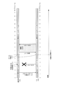
図4は、基地局402がUE404と通信している、マルチビーム通信を示す図の400である。図4を参照すると、UE404がオンすると、UE404は近くのNRネットワークを探す。UE404は、NRネットワークに属する基地局402を発見する。基地局402は、PSS、SSS、およびPBCH(MIBを含む)を含むSSブロックを、異なる送信方向402a〜402hにおいて定期的に送信する。UE404は、PSS、SSS、およびPBCHを含む、送信方向402eにおける送信を受信する。受信されたSSブロックに基づいて、UE404は、NRネットワークに同期し、基地局402と関連付けられるセルにキャンプオンする。
FIG. 4 is a diagram 400 showing multi-beam communication in which the
図5は、複数のビームを介した基地局とUEとの間の通信の図を含む。いくつかの例では、図の560および561は、基地局562とUE566との間のmmW通信を図示する。図の560は、単にビーム510および512と呼ばれることがあるビームセット510および512のうちの少なくとも1つを介して基地局562(たとえば、基地局の例)がUE566に送信する場合を図示する。ビーム510/512は、以前のセクションにおいて論じられたDL/UL信号を搬送し得る。図の561は、ビーム520および522のうちの少なくとも1つを介してUE566が基地局562に送信する場合を図示する。ビーム520/522は、以前のセクションにおいて論じられたDL/UL信号を搬送し得る。たとえば、第1のビームペア550のビーム510および第2のビームペア552のビーム512がDL信号を搬送する。第1のビームペア550のビーム520および第2のビームペア552のビーム522がUL信号を搬送する。
FIG. 5 includes a diagram of communication between the base station and the UE via multiple beams. In some examples, 560 and 561 in the figure illustrate mmW communication between
ビーム510、512、520、および522の各々は2つ以上のビームを含み得る。これに関して、ビームセットは1つまたは複数のビームを含み得る。たとえば、ビーム510は、制御信号および制御チャネルを搬送するためのビーム510_Cと、データ信号およびデータチャネルを搬送するためのビーム510_Dとを含み得る。いくつかの例では、これらのビームは関連付けられ得る。たとえば、ある場合には、基地局562およびUE566はビーム510およびビーム520を介して通信し得る。すなわち、基地局562は、ビーム510を介してUE566に送信し、ビーム520を介してUE566から受信し得る。したがって、ビーム510および520は関連付けられ、ビームペアと呼ばれ得る。たとえば、ビーム510および関連するビーム520は第1のビームペア550と呼ばれることがあり、ビーム512および関連するビーム522は第2のビームペア552と呼ばれることがある。
Each of the
基地局(たとえば、gNB)562およびUE566は、有効なビームペア(たとえば、第1のビームペア550および/または第2のビームペア552)を通じて通信し得る。有効なビームペアは、PDSCH、PDCCH、PUSCH、およびPUCCHなどのデータチャネルおよび制御チャネルを搬送する、基地局562およびUE566のビームペアであり得る。一態様では、基地局562は、測定基準信号(MRS)、CSI-RS、一次同期信号、および二次同期信号(SYNC)などの、信号の報告された測定結果(たとえば、基地局からのビームによりUE566によって報告される(たとえば、基地局はそのようなビームを直接測定することによってUEからのビームを監視することができる))を使用して有効なビームペアを監視し得る。そうするために、基地局562は、測定要求、たとえばビーム状態情報要求をUE566に送信し得る。UE566は、それに応答して、測定信号を測定し、測定される各ビームについてのビームの識別情報およびビームの品質を含む報告を送信し得る。基地局562は次いで、ビームの切替えをUEにシグナリングし得る。ビーム切替え信号(たとえば、メッセージ)は、基地局562およびUE566のビームペアを切り替えるための、ターゲットビーム識別子(たとえば、ターゲットビームペアを識別する)および/または時間を含み得る。この時間は、たとえば、サブフレーム、スロット、またはミニスロットに関して示され得る(たとえば、サブフレーム、スロット、またはミニスロット識別子もしくはオフセットを指定する)。いくつかの例では、基地局562は、明示的なビーム識別子なしでビームペアを切り替えるようにシグナリングし得る。たとえば、ビームの切替えは、ビームペアを切り替えるための信号の送信の前の取り決めに基づき得る。そのような時間において、基地局562とUE566の両方がビームペアを切り替える(たとえば、ソースである第1のビームペア550からターゲットである第2のビームペア552に切り替える)ことができる。
Base stations (eg, gNB) 562 and UE566 may communicate through a valid beam pair (eg, first beam pair 550 and / or second beam pair 552). A valid beam pair can be a beam pair of
UE566は、ビームの切替えのための応答メッセージを基地局562に送信し得る。いくつかの例では、UE566はビームの切替えをシグナリングすることができ、基地局562は上で説明されたような応答メッセージを送信することができる。与えられる実施形態は基地局562がビームの切替えを開始する(およびUE566がビームの切替えを確認する)ことに関するが、同様の例は、UE566がビームの切替えを開始する(および基地局562がビームの切替えを確認する)例に適用されることを理解されたい。
The
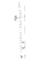
図6は、様々な実施形態による単一切替えビーム切替えメッセージの例を示す。図6において、基地局601は、サブフレーム0において第1のビームセット605を介してUE603と通信している。基地局601およびUE603は、たとえば、上の図5においてそれぞれ基地局562およびUE566であり得る。サブフレーム1において、基地局601は、第1のビームセット605を介してBSM607をUE603に送信する。BSM607は、切替え時間611においてUE603が第1のビームセット605を介した通信から第2のビームセット609を介した通信に切り替えるための命令を含む。BSM607は単一切替えBSMの例であり、それはBSM607がUE603に一度だけビームの切替えを実行するように命令するからである。この例では、基地局601は、予想されるACK時間613においてUEから応答メッセージを、たとえばACKを受信すると予想するので、基地局はその応答メッセージを監視している。本明細書で提示される現在の例および他の例の様々な実施形態では、応答メッセージは、BSMまたは他の信号が受信されたことの任意の指示であり得る。たとえば、応答メッセージは、BSMまたは他の信号に応答した、ACK、受信信号強度インジケータ(RSSI)、SNR、測定報告などであり得る。応答メッセージの監視は、能動的または受動的に行われ得る。たとえば、基地局は、監視するために能動的に測定を行うことがあり、たとえば、応答メッセージが予想される特定の周波数またはチャネルに合わせることがある。一方、基地局は、たとえば通常の動作の過程において応答メッセージを受信することを単に予想することによって、受動的に監視することがある。
FIG. 6 shows examples of single switching beam switching messages according to various embodiments. In FIG. 6,
UE603は、BSM607を受信し、予想されるACK時間613において基地局601が受信するためのACK615を送信する。基地局601は予想されるACK時間613においてACK615を受信し、結果として、基地局601はUE603がビームの切替えを実行するであろうことを知る。切替え時間611において、基地局601およびUE603は、第1のビームセット605から第2のビームセット609へのビーム切替え617を実行する。
The
サブフレーム9において、基地局601は、再びビームを切り替えることを決め、第2のビームセット609を介してBSM619をUE603に送信することができる。BSM619は、切替え時間623においてUE603が第2のビームセット609を介した通信から第3のビームセット621を介した通信に切り替えるための命令を含む。BSM619は単一切替えBSMの別の例であり、それはBSM619がUE603に一度だけビームの切替えを実行するように命令するからである。基地局601は予想されるACK時間625においてACKを監視する。UE603は、BSM619を受信し、予想されるACK時間625において基地局601が受信するためのACK627を送信する。基地局601は予想されるACK時間625においてACK627を受信し、結果として、基地局601はUE603がビームの切替えを実行するであろうことを知る。切替え時間623において、基地局601およびUE603は、第2のビームセット609から第3のビームセット621へのビーム切替え629を実行する。したがって、図6の例では、BSM607およびBSM619は単一切替えBSMの例である。
In
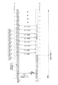
図7は、様々な実施形態による複数切替えBSMの例を示す。図7において、基地局701は、サブフレーム0において第1のビームセット705を介してUE703と通信している。サブフレーム1において、基地局701は、第1のビームセット705を介してBSM707をUE703に送信する。BSM707は、UE703が、第1の切替え時間711において第1のビームセット705を介した通信から第2のビームセット709を介した通信に切り替え、第2の切替え時間723において第2のビームセット709を介した通信から第3のビームセット721を介した通信に切り替えるための命令を含む。BSM707は複数切替えBSMの例であり、それはBSM707がUE703に複数回ビームの切替えを実行するように命令するからである。この例では、基地局701は、予想されるACK時間713においてUEから応答メッセージを、たとえばACKを受信すると予想するので、基地局はその応答メッセージを監視している。
FIG. 7 shows examples of multiple switching BSMs according to various embodiments. In FIG. 7,
UE703は、BSM707を受信し、予想されるACK時間713において基地局701が受信するためのACK715を送信する。基地局701は予想されるACK時間713においてACK715を受信し、結果として、基地局701はUE703がビームの切替えを実行するであろうことを知る。第1の切替え時間711において、基地局701およびUE703は、第1のビームセット705から第2のビームセット709へのビーム切替え717を実行する。第2の切替え時間723において、基地局701およびUE703は、第2のビームセット709から第3のビームセット721へのビーム切替え729を実行する。したがって、BSM707は複数切替えBSMの例であり、それはBSM707が複数回ビームの切替えを実行するための命令を含むからである。
The
様々な実施形態では、複数切替えBSMが有用であり得る。たとえば、図6および図7の比較が示すように、複数切替えBSMを使用して複数のビーム切替えをシグナリングすることは、最初のビーム切替えの後の各ビーム切替えのための追加のBSMおよびACKの必要性をなくすことによって、シグナリングの量を減らすことができる。また、複数のビーム切替えに必要とされるBSMおよびACKの数を減らすことによって、複数切替えBSMは、信号の障害が発生し得る事例の数を減らすことができる。したがって、複数切替えBSMを使用するシステムは、信号の障害の影響をより受けないことがある。 In various embodiments, a multi-switching BSM may be useful. For example, as the comparison in FIGS. 6 and 7 shows, signaling multiple beam switches using a multiple switch BSM can be an additional BSM and ACK for each beam switch after the first beam switch. By eliminating the need, the amount of signaling can be reduced. Also, by reducing the number of BSMs and ACKs required for multiple beam switching, the multiple switching BSM can reduce the number of cases where signal failure can occur. Therefore, systems using multiple switching BSMs may be less susceptible to signal failures.
複数切替えBSMは、たとえば、複数のビーム切替えがBSMの送信の前に決定され得るときに使用され得る。たとえば、UEが予測可能な方法で複数のビームセットのカバレッジエリアを通過する通信システムでは、基地局は、複数のビーム切替えがUEと通信し続けるために必要であろうと、ある時間において予測することが可能であり得る。たとえば、ある基地局が、列車が基地局の複数のビームセットを通じて既知の速度でその上を移動する路線にサービスすることがある。その基地局は、たとえば、南に向かう列車で移動しているUEがその基地局のカバレッジエリアにいつ到達するかを知ることができ、UEは、その基地局の第1のビームセットとの接続を確立する。その基地局はまた、南に向かう列車が第1のビームセットを通過して第2のビームセットに到達するのに第1の長さの時間がかかること、第2のビームセットを通過して第3のビームセットに到達するのに第2の長さの時間がかかることなどを知り得る。したがって、新しいUEが第1のビームセットを介して接続を確立したと基地局が決定するとき、基地局は、第1のビームセットから第2のビームセットへの第1のビーム切替えが第1の長さの時間の後に発生すべきであることと、第2のビームセットから第3のビームセットへの第2のビーム切替えが第1のビーム切替えから第2の長さの時間の後に発生すべきであることとを予測し得る。したがって、基地局は、たとえば第1のビームセットとの接続が確立された直後に、各々の南に向かうUEに複数切替えBSMを送信し得る。このようにして、たとえば、基地局は、複数のBSMおよびACKと関連付けられる潜在的な信号誤りとともに、BSMおよび対応するACKの数を大きく減らすことが可能であり得る。 Multiple switching BSMs can be used, for example, when multiple beam switchings can be determined prior to transmission of the BSM. For example, in a communication system in which the UE traverses the coverage area of multiple beam sets in a predictable manner, the base station predicts at a given time that multiple beam switchings will be required to continue communicating with the UE. Can be possible. For example, a base station may serve a line on which a train travels at a known speed through multiple beam sets of the base station. The base station, for example, can know when a UE traveling by train heading south will reach the coverage area of the base station, and the UE will connect to the base station's first beamset. To establish. The base station also passes through the second beamset, where the train heading south passes through the first beamset and takes the first length of time to reach the second beamset. You can see that it takes a second length to reach the third beam set, and so on. Therefore, when the base station determines that the new UE has established a connection through the first beam set, the base station will first switch the first beam from the first beam set to the second beam set. The second beam switch from the second beam set to the third beam set occurs after the second beam switch from the first beam switch. You can predict that it should be. Thus, a base station may transmit multiple switching BSMs to each southbound UE, for example, immediately after a connection with a first beam set is established. In this way, for example, a base station may be able to significantly reduce the number of BSMs and corresponding ACKs, along with potential signal errors associated with multiple BSMs and ACKs.
しかしながら、単一切替えBSMまたは複数切替えBSMが使用されるかどうかとは無関係に、信号誤りは発生し得る。いくつかの例では、基地局は、UEからの予想される応答メッセージをタイムリーに受信しない。 However, signal errors can occur regardless of whether a single-switching BSM or a multi-switching BSM is used. In some examples, the base station does not receive the expected response message from the UE in a timely manner.
図8は、マルチビームワイヤレス通信における信号誤りの例示的な状況を示す。この例では、基地局801およびUE803は第1のビームセット805を介して通信しており、基地局801は切替え時間809においてビームを切り替えるようにUE803に命令するBSM807を送信する。しかしながら、UE803はBSM807を受信しない。UE803はBSM807を受信しないので、UE803はACKを送信せず、基地局801は予想されるACK時間811においてACKを受信しない。基地局801は、UE803が切替え時間809においてビームを切り替えるであろうかどうかを知らず、それは、基地局801が、UE803がBSM807を受信することに失敗したか、またはUE803がBSM807を受信して、基地局801により受信されなかったACKを送信したかを知らないからである。この場合、UE803は切替え時間809においてビームセットを切り替えないが、第1のビームセット805を介して通信し続ける。
FIG. 8 illustrates an exemplary situation of signal error in multi-beam wireless communication. In this example,
図9は、マルチビームワイヤレス通信における信号誤りの別の例示的な状況を示す。この例では、基地局901およびUE903は第1のビームセット905を介して通信しており、基地局901は切替え時間909においてビームを第2のビームセット908へ切り替えるようにUE903に命令するBSM907を送信する。この例では、UE903はBSM907を受信してACK910を送信する。しかしながら、基地局901は予想されるACK時間911においてACK910を受信しない。図8の例におけるように、基地局901は、UE903が切替え時間909においてビームを切り替えるであろうかどうかを知らず、それは、基地局901が、UE903がBSM907を受信することに失敗したか、またはUE903がBSM907を受信して、基地局901により受信されなかったACKを送信したかを知らないからである。この場合、UE903は、ビーム切替え913を実行して、切替え時間909において第2のビームセット908を介した通信に切り替える。
FIG. 9 shows another exemplary situation of signal error in multi-beam wireless communication. In this example,
図8および図9に関して説明された両方のシナリオの結果、基地局は応答メッセージ(たとえば、UEからのACK)を受信しないので、基地局は、UEがターゲットビームセットに切り替えるであろうかどうかを知らないことがある。基地局は切替え時間においてターゲットビームセットに切り替えるが、UEは切り替えない場合、ビームの不整合が生じ得る(たとえば、送信側の装置と受信側の装置が異なるビームペアを介して通信する)。同様に、UEは切替え時間においてターゲットビームセットに切り替えるが、基地局は切り替えない場合、ビームの不整合が生じ得る。 As a result of both scenarios described with respect to FIGS. 8 and 9, the base station does not receive an acknowledgment message (eg, ACK from the UE), so the base station knows if the UE will switch to the target beam set. Sometimes not. If the base station switches to the target beam set at the switch time, but the UE does not, beam mismatch can occur (for example, the transmitting device and the receiving device communicate through different beam pairs). Similarly, if the UE switches to the target beam set at the switching time, but the base station does not, beam inconsistency can occur.
本明細書で説明される様々な実施形態のいくつかの実装形態は、たとえば、上で説明されたようなBSMまたはACKの送達失敗などのシグナリングエラーが原因の、ビームの不整合の影響を回避するのを助け、またはそれを軽減するのを助け得ることに留意されたい。具体的には、図11および図12は、切替え時間の前に実施され得る例示的なビーム切替え方法を示す。図14〜図18は、切替え時間の後に実施され得る例示的なビーム切替え方法を示す。図19は、BSMシグナリングエラーおよびACKシグナリングエラーを完全に回避するために実施され得る、例示的なビーム切替え方法を示す。 Some implementations of the various embodiments described herein avoid the effects of beam inconsistencies due to signaling errors such as BSM or ACK delivery failures as described above. Note that it can help or mitigate it. Specifically, FIGS. 11 and 12 show exemplary beam switching methods that can be performed prior to the switching time. 14-18 show exemplary beam switching methods that can be performed after the switching time. FIG. 19 shows an exemplary beam switching method that can be implemented to completely avoid BSM signaling errors and ACK signaling errors.
まず図10〜図13を見ると、これらの図は、ビーム切替えメッセージがビームリセット状態を示すことができるシステムおよび方法の様々な例を説明し、このことはマルチビームシステムにおけるビームの切替えに利点をもたらし得る。図10は、BSMが、以前のビーム切替え命令の実行を続けることを示すことができるか、または以前のビーム切替え命令を無視することを示すことができるかのいずれかである、2つのリセット状態を示す。図11および図12は、リセット状態を示すBSMが、時間のかかるビーム回復手順を回避してビームの不整合の事例を軽減するのを助けることができる、2つの例示的な方法を示す。図13は、図7に関して上で説明されたものなどの、複数切替えBSMにおけるビームリセット状態の例示的な使用を示す。 First looking at FIGS. 10-13, these figures illustrate various examples of systems and methods in which beam switching messages can indicate a beam reset state, which is advantageous for beam switching in multi-beam systems. Can bring. Figure 10 shows two reset states, either the BSM can be shown to continue executing the previous beam switching instruction, or it can be shown to ignore the previous beam switching instruction. Is shown. 11 and 12 show two exemplary methods in which a reset state BSM can help avoid time-consuming beam recovery procedures and mitigate cases of beam inconsistency. FIG. 13 illustrates an exemplary use of a beam reset state in a multi-switching BSM, such as that described above for FIG.
図10A〜図10Cは、様々な実施形態による、ワイヤレス通信の方法の例示的な実装形態を示す。図10Aは、第1の時間における基地局1001とUE1003との間の通信の状態を示す。図10Bは、第1のリセット状態が選択される場合の後の時間における基地局1001とUE1003との間の通信の状態を示す。図10Cは、第2のリセット状態が選択される場合の後の時間における基地局1001とUE1003との間の通信の状態を示す。まず図10Aを見ると、基地局1001は、ビームをUE1003に切り替えるための第1の命令を含むBSM1005を送信することができ、これは計画されたビーム切替え1007を確立することができる。たとえば、基地局1001およびUE1003は第1のビームセットを介して通信していることがあり、BSM1005は第2のビームセットへ切り替えるようにUE1003に命令する。UE1003はBSM1005を受信してACK1009を送信し、基地局はACK1009を受信する。
10A-10C show exemplary implementations of wireless communication methods according to various embodiments. FIG. 10A shows the state of communication between the
基地局1001は第2のBSMをUE1003に送信することを決め、基地局1001は第2のBSMによって示されることになるリセット状態を選択する。図10Bおよび図10Cはそれぞれ、第1のリセット状態および第2のリセット状態の選択に起因する通信を示す。
図10Bは第1のリセット状態に基づく通信を示し、ここで、UE1003はBSM1005において送信される第1の命令を無視する。基地局1001はBSM1011をUE1003に送信する。BSM1011は、新しいビーム切替え1013を確立することができるビームを切り替えるための第2の命令を含み、UE1003が第1の命令を無視する選択されたリセット状態を示す。UE1003はBSM1011を受信してACK1015を送信し、基地局はACK1015を受信する。この例では、UE1003は第1の命令の実行を完了しておらず、それはUE1003が計画されたビーム切替え1007を実行していないからである。したがって、UE1003は、図10において無視されるビーム切替え1017として表される計画されたビーム切替え1007を無視し、新しいビーム切替え1013だけを実行する。
FIG. 10B shows the communication based on the first reset state, where the
一方、図10Cは第2のリセット状態に基づく通信を示し、ここで、UE1003はBSM1005において送信される第1の命令の実行を維持するので、UE1003は第2の命令で第1の命令を補強する。基地局1001はBSM1019をUE1003に送信する。BSM1019は、追加されるビーム切替え1021を確立することができるビームを切り替えるための第2の命令を含み、UE1003が第1の命令の実行を維持する選択されたリセット状態を示す。UE1003はBSM1019を受信してACK1023を送信し、基地局はACK1023を受信する。この例では、UE1003は第1の命令の実行を完了しておらず、それはUE1003が計画されたビーム切替え1007を実行していないからである。UE1003は、計画されたビーム切替え1007を実行することによって第1の命令の実行を維持し、追加されたビーム切替え1021も実行することによって第2の命令で第1の命令を補強する。
On the other hand, FIG. 10C shows the communication based on the second reset state, where the UE1003 maintains the execution of the first instruction transmitted in the BSM1005, so that the UE1003 reinforces the first instruction with the second instruction. do.
様々な実施形態では、第2のBSMは、フラグなどのビットを0または1に設定することによって、リセット状態のいずれが選択されたかを示し得る。たとえば、0に設定されたビットは第1の命令の実行を維持することを示すことがあり、1に設定されたビットは第1の命令を無視することを示すことがある。様々な実施形態では、第2のBSMはインジケータを提供しないことによって選択された状態の1つを示し得る。言い換えると、第2のBSMは、リセット状態の1つが選択されたという情報を除くことによって、選択された状態の1つを示し得る。たとえば、インジケータが提供されない場合、UEはデフォルトでリセット状態の1つになることがあり、たとえば第1の命令をデフォルトで無視する。いくつかの例では、リセット状態フィールドは、HARQ動作のための新しいデータインジケータまたはNDIビットと同様に動作し得る。いくつかの例では、リセット状態情報は空のフィールドであり得る(たとえば、リセット状態がヌルフラグを示し、またはビーム切替えメッセージにおいてリセット状態情報が提供されない)。 In various embodiments, the second BSM may indicate which of the reset states was selected by setting a bit such as a flag to 0 or 1. For example, a bit set to 0 may indicate to keep the execution of the first instruction, and a bit set to 1 may indicate to ignore the first instruction. In various embodiments, the second BSM may indicate one of the selected states by not providing an indicator. In other words, the second BSM may indicate one of the selected states by removing the information that one of the reset states has been selected. For example, if no indicator is provided, the UE may be in one of the reset states by default, for example ignoring the first instruction by default. In some examples, the reset state field may behave like a new data indicator or NDI bit for HARQ operation. In some examples, the reset state information can be an empty field (for example, the reset state indicates a null flag, or the beam switch message does not provide the reset state information).
図11および図12がここで論じられる。これらの図は、上で説明されたような信号誤りが原因の起こり得るビームの不整合を回避するのを助け、それによって、時間のかかるビーム回復手順を潜在的に回避するのを助けるために、切替え時間の前に実施され得る様々な実施形態を示す。 Figures 11 and 12 are discussed here. These figures help avoid possible beam inconsistencies due to signal errors as described above, thereby potentially avoiding time-consuming beam recovery procedures. , Various embodiments that can be implemented before the switching time are shown.
図11A〜図11Cは、様々な実施形態による、ワイヤレス通信の方法の例示的な実装形態を示す。図11Aは第1の時間における基地局1101とUE1103との間の通信の状態を示し、図11Bは第1の時間より後の第2の時間における基地局1101とUE1103との間の通信の状態を示し、図11Cは第2の時間より後の第3の時間における基地局1101とUE1103との間の通信の状態を示す。まず図11Aを見ると、基地局1101はBSM1105をUE1103に送信することができる。たとえば、基地局1101およびUE1103は第1のビームセットを介して通信していることがあり、BSM1105は第2のビームセットへ切り替えるようにUE1103に命令する。したがって、BSM1105は計画されたビーム切替え1107を確立する。この例では、基地局1101は、予想されるACK時間1109においてUE1103からの応答メッセージを予想する。UE1103は、BSM1105を受信してACK1111を送信する。しかしながら、基地局1101はACK1111を受信しないので、基地局は、UE1103が計画されたビーム切替え1107を実行するであろうかどうかを知らない。
11A-11C show exemplary implementations of wireless communication methods according to various embodiments. FIG. 11A shows the communication status between the
図11Bを見ると、予想されるACK時間1109と計画されたビーム切替え1107との間に存在する時間が不十分であるので、基地局1101は、計画されたビーム切替え1107より後の時間に新しいビーム切替え1115を確立するBSM1113をUE1103に送信する。UE1103はBSM1113を受信し、UE1103のデフォルトの挙動は、UEが新しいBSMを受信する場合に以前のBSMにおけるあらゆる命令の実行を取り消すというものであるので、計画されたビーム切替え1107は無視されるビーム切替え1117になる。基地局1101は予想されるACK時間1119において応答メッセージを監視する。UE1103はACK1121を送信する。しかしながら、基地局1101はACK1121を受信しないので、基地局は、UE1103が新しいビーム切替え1115を実行するであろうかどうかを知らない。しかしながら、BSM1113はビーム切替えを遅らせるようにUE1103に命令したので、基地局1101は、別のBSMを送信し、新しいビーム切替え1115の前に応答メッセージを場合によっては受信することが可能である。
Looking at Figure 11B,
図11Cを見ると、ビーム切替え(すなわち、新しいビーム切替え1115)の前に存在する時間がやはり不十分であるので、基地局1101は、新しいビーム切替え1115より後の時間に新しいビーム切替え1125を確立するBSM1123をUE1103に送信する。UE1103はBSM1123を受信し、新しいビーム切替え1115は無視されるビーム切替え1127になる。基地局1101は予想されるACK時間1129において応答メッセージを監視する。UE1103はACK1131を送信する。このとき、基地局1101はACK1131を受信し、基地局1101とUE1103の両方が、新しいビーム切替え1125に従ってビームを切り替えることができる。したがって、計画されたビーム切替えを遅らせることによって、基地局およびUEは、応答が受信されるまでソースビームセット上で通信を続け得る。対照的に、基地局1101が計画されたビーム切替えを遅らせなければ、たとえば、計画されたビーム切替え1107の時間に、時間のかかるビーム回復プロセスが開始された可能性がある。
Looking at Figure 11C,
図12A〜図12Bは、様々な実施形態による、複数のビームを介した例示的なワイヤレス通信を示す。具体的には、図12Aは第1の時間における基地局1201とUE1203との間の通信の状態を示し、図12Bは後の時間における基地局1201とUE1203との間の通信の状態を示す。まず図12Aを見ると、基地局1201はBSM1205をUE1203に送信することができる。たとえば、基地局1201およびUE1203は第1のビームセットを介して通信していることがあり、BSM1205は第2のビームセットへ切り替えるようにUE1203に命令する。したがって、BSM1205は計画されたビーム切替え1207を確立する。この例では、基地局1201は、予想されるACK時間1209においてUE1203からの応答メッセージを予想する。しかしながら、基地局1201は応答メッセージを受信しないので、基地局は、UE1203が計画されたビーム切替え1207を実行するであろうかどうかを知らない。
12A-12B show exemplary wireless communication over multiple beams according to various embodiments. Specifically, FIG. 12A shows the state of communication between the
図12Bを見ると、予想されるACK時間1209と計画されたビーム切替え1207との間に十分な時間が存在するので、基地局1201は別のBSM1211をUE1203に送信する。BSM1211は新しいビーム切替え1213を確立する。この例では、新しいビーム切替え1213は計画されたビーム切替え1207と同じであり、すなわち、同じターゲットビームセットと同じ切替え時間である。基地局1201は予想されるACK時間1215において応答メッセージを監視する。この例では、UE1203は、BSM1205を受信し、基地局1201によって受信されるACK1217を送信する。この例では、UE1203のデフォルトの挙動は、UEが新しいBSMを受信する場合、以前のBSMにおけるあらゆる命令の実行を取り消すというものである。この場合、基地局1201およびUE1203はともに、ターゲットビームセットに切り替え、通信を続けることができる。この手法は、第1のBSMと計画されたビーム切替えとの間に十分な時間がある場合には、基地局およびUEがソースビームセットを介した通信を続けることができるので、うまく機能し得る。しかしながら、いくつかの場合、基地局には、UEと有効に通信するための十分な時間が、計画されたビーム切替えの前にないことがある。
Looking at Figure 12B, there is sufficient time between the expected ACK time 1209 and the planned beam switching 1207, so
図13A〜図13Bは、様々な実施形態による、ワイヤレス通信の方法の別の例示的な実装形態を示す。具体的には、図13A〜図13Bは、複数切替えBSMを伴う実装形態におけるリセット状態の例示的な使用を示す。図13Aは第1の時間における基地局1301とUE1303との間の通信の状態を示し、図13Bは第1のリセット状態が選択される場合の後の時間における基地局1301とUE1303との間の通信の状態を示す。まず図13Aを見ると、基地局1301は、ビームをUE1303に切り替えるための第1の命令を含むBSM1305を送信することができる。この場合、第1の命令は、図7に関して上で説明されたBSM707などの、複数のビーム切替えを含む。BSM1305は、2つの計画されたビーム切替え、すなわち、計画されたビーム切替え1307および計画されたビーム切替え1308を確立する。たとえば、基地局1301およびUE1303は第1のビームセットを介して通信していることがあり、BSM1305は、計画されたビーム切替え1307のために第2のビームセットへ切り替えるように、かつ計画されたビーム切替え1308のために第3のビームセットへ切り替えるように、UE1303に命令する。UE1303はBSM1305を受信してACK1309を送信し、基地局はACK1309を受信する。
13A-13B show another exemplary implementation of a method of wireless communication, with various embodiments. Specifically, FIGS. 13A-13B show exemplary use of the reset state in an implementation with multiple switching BSMs. FIG. 13A shows the state of communication between
基地局1301は第2のBSMをUE1303に送信することを決め、基地局1301は第2のBSMによって示されることになるリセット状態を選択する。図13Bは、UE1303が第1の命令の実行を維持するようなリセット状態の選択に起因する通信を示す。図10Cの例とは異なり、基地局1301は、UE1303がビーム切替えのために第1の命令の実行を開始した後で、第2のBSMを送信する。しかしながら、第2のBSMは、UE1303が第1の命令の実行を完了する前に送信される。
図13Bは第1のリセット状態に基づく通信を示し、ここで、UE1303はBSM1305において送信される第1の命令の実行を維持する。基地局1301は、計画されたビーム切替え1307が完了した後で、BSM1311をUE1303に送信する。計画されたビーム切替え1307の完了が、完了したビーム切替え1312によって図13Bにおいて示される。BSM1311は、追加されるビーム切替え1313を確立することができるビームを切り替えるための第2の命令を含み、UE1303が第1の命令の実行を維持する選択されたリセット状態を示す。この場合、UE1303は第1の命令の実行を完了しておらず、それはUEが計画されたビーム切替え1308を完了していないからである。UE1303はBSM1305を受信してACK1315を送信し、基地局はACK1315を受信する。この例では、UE1303は第1の命令の実行を完了しておらず、それはUE1303が計画されたビーム切替え1308を実行していないからである。したがって、UE1303は、追加されたビーム切替え1313で計画されたビーム切替え1308を補強する。
FIG. 13B shows the communication based on the first reset state, where the
様々な実施形態では、BSM1311は、図10Bの例と同様に、UE1303が第1の命令を無視するリセット状態を示し得る。この場合、完了したビーム切替え1312がすでに実行されているとしても、UE1303は計画されたビーム切替え1308を無視することができる。言い換えると、UE1303は、第1の命令の予想されない部分を無視することができる。
In various embodiments, the
ここで図14〜図18を見ると、これらの図は、上で説明されたものなどの信号誤りが原因で起こり得るビームの不整合から回復するための、切替え時間の後に実施され得る例示的なビーム切替え方法を示す。 Now looking at FIGS. 14-18, these figures are exemplary which can be performed after the switching time to recover from possible beam inconsistencies due to signal errors such as those described above. The beam switching method is shown.
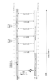
図14は、様々な実施形態による、ワイヤレス通信の方法の例示的な実装形態を示す。最初に、基地局1401およびUE1403は、たとえばmmW通信を使用して、第1のビームセット1405を介して通信していることがある。基地局1401およびUE1403は、たとえば、上の図5における基地局562およびUE566に相当することがあり、基地局1401は、1つまたは複数のビーム510などの、第1のビームセット1405を介して様々なDL信号およびチャネルをUE1403に送信することがある。UE1403は、1つまたは複数のビーム520(これらは第1のビームペア550の中の1つまたは複数のビーム510、たとえば第1のビームセット1405と関連付けられる)などの、第1のビームセット1405を介して様々なUL信号およびチャネルを基地局1401に送信することがある。
FIG. 14 shows exemplary implementations of wireless communication methods according to various embodiments. First,
基地局1401は、切替え時間1411において第2のビームセット1409を介した通信に切り替えるための命令を含むBSM1407を送信することができる。BSM1407は、たとえば第2のビームペア552であり得る、ターゲットビームとも呼ばれる第2のビームセット1409のためのビーム識別子の情報を含み得る。いくつかの例では、BSM1407はビーム識別子を含まないことがある。いくつかの例では、BSM1407はMACまたはRRCメッセージの一部として送信されることがある。基地局1401は、予想されるACK時間1413においてUE1403からの応答メッセージ、たとえばACKを予想することがあるので、BSM1407の受信を示す応答を監視していることがある。UE1403は、ターゲットビーム(第2のビームセット)識別子をエコーバックするために、UL送信にターゲットビーム識別子を含め得る。一態様では、UE1403は、ターゲットビーム識別子からシーケンスを生成し、そのシーケンスをUL送信に含め得る。基地局1401は、UL送信の中のそのシーケンスからターゲットビームペアを決定して確認し得る。いくつかの例では、ソースビームペア(第1のビームセット)とターゲットビームペアの両方が、通信に十分な品質をもつことがあり、この機構は、ソースビームペアとターゲットビームペアのいずれを使用すべきかを基地局1401が決定するのを助け得る。
しかしながら、この例では、応答メッセージが受信されたかどうかを基地局が決定するとき、基地局1401は、ACKが受信されなかったこと、すなわち応答メッセージが受信されないことを決定する。したがって、切替え時間の後でUE1403がその上で通信しているであろうビームセットは基地局1401に知られず、この状況が、UE1403が切替え時間1411の後でその上で通信している未知のビームセット1414によって、図14において表されている。UE1403がビームを切り替えるであろうかどうかを基地局1401が知らないとしても、基地局1401は切替え時間1411において第2のビームセット1409へのビーム切替え1415を実行する。
However, in this example, when the base station determines whether a response message has been received, the
基地局1401は次いで、ビーム切替え1415を実行した後で、第2のビームセット1409を介して信号1417をUE1403に送信することができる。様々な実施形態では、信号1417は、たとえば、UE1403が第2のビームセット1409を介して通信している応答に対する要求であり得る。様々な実施形態では、信号1417は、たとえば、基地局1401とUE1403との間の通常の通信(たとえば、制御信号およびデータ信号)の単なる継続であり得る。これに関して、基地局1401は、信号1417に応答してACKを監視することがあり、信号1417に応答した通常の通信を監視することなどがある。いくつかの実施形態では、基地局は、ビームを切り替えた後で、信号1417などの信号を送信しないことがあり、単にビームを切り替えて、次いで第2のビームセットを介したUE1403からの通信を待機することがある。
図14の例では、基地局1401は信号1417へのACKを監視する。UE1403がBSM1407を受信し、第2のビームセット1409を介した通信に切り替えた場合、UE1403はACK1419を基地局1401に送信することができる。この場合、基地局1401は、ACK1419を受信することができ、第2のビームセット1409を介してUE1403との通信を続けることができる。言い換えると、未知のビームセット1414は今や第2のビームセット1409だと知られており、図14に示される残りのビームの切り替え、信号、および潜在的なACKは無視され得る。
In the example of FIG. 14,
しかしながら、UE1403がBSM1407を受信せず、第2のビームセット1409に切り替えなかったとすれば、UE1403は、第2のビームセットに切り替えなかったので、基地局1401から信号1417を受信しない。この場合、UE1403はACK1419を送信しない。ACK1419は送信されることもされないこともあるので、ACK1419は破線の矢印として示される。この破線の矢印の表現は、送信されることもされないこともある他の信号のために本明細書において使用される。
However, if UE1403 did not receive BSM1407 and did not switch to the second beamset 1409, then UE1403 did not switch to the second beamset and therefore does not receive signal 1417 from
基地局1401がACK1419を受信しない場合、基地局1401は、ビーム切替え1421を実行して第1のビームセット1405に通信を戻すことができる。言い換えると、UE1403が切替え時間1411の後に第2のビームセット1409を介して通信していない場合、基地局1401は、UE1403がBSM1407を受信しなかったのでまだ第1のビームセット1405を介して通信していると想定できる。ビーム切替え1421の後で、基地局1401は、第1のビームセット1405を介して信号1423をUE1403に送信し、ACKを監視することができる。UE1403はACK1425を送信することもしないこともある。基地局1401がACK1425を受信する場合、基地局1401およびUE1403は、第1のビームセット1405上で、上で説明されたように通信を続けることができる(すなわち、未知のビームセット1414は今や第1のビームセット1405として知られている)。しかしながら、基地局1401がACK1425を受信しない場合、基地局1401は、たとえば、ビーム切替え1427を実行し、信号1429を送信し、ACK1431を監視することによって、第1のビームセットと第2のビームセットとの間で切り替えることを繰り返すことができる。
If
いくつかの実施形態では、基地局1401は、第1のビームセット1405に戻した後で信号1423を送信しないことがあり、それは、UE1403がビームを切り替えなかったので、第1のビームセット上で通信している確率が高い可能性があるからであることに留意されたい。したがって、UE1403がビームを切り替えなかったと決定した後で第1のビームセットに戻るとき、基地局1401が通常の通信を単に続けることがより効率的であり得る。
In some embodiments,
図15および図16は、2つの異なるシグナリングエラーの状況における図14に示される例を示す。 15 and 16 show an example shown in FIG. 14 in two different signaling error situations.
図15は、BSMへの応答が失われる状況における図14の実装形態を示す。最初に、基地局1501およびUE1503は、たとえばmmW通信を使用して、第1のビームセット1505を介して通信していることがある。基地局1501は、切替え時間1511において第2のビームセット1509を介した通信に切り替えるための命令を含むBSM1507を送信することができる。基地局1501は、予想されるACK時間1513においてUE1503からの応答メッセージ、たとえばACKを予想することがあるので、BSM1507の受信を示す応答を監視していることがある。この例では、UE1503はBSM1507を受信し、応答メッセージ、たとえばACK1525を送信する。UE1503は、切替え時間1511において第2のビームセット1509を介した通信に切り替えることを準備する。
FIG. 15 shows the implementation of FIG. 14 in a situation where the response to the BSM is lost. First,
しかしながら、この例では、ACK1525は失われ、たとえば基地局1501によって受信されない。したがって、基地局1501は、ACKが受信されなかったこと、すなわち応答メッセージが受信されないことを決定する。したがって、UE1503が切替え時間の後でその上で通信しているであろうビームセットは、基地局1501に知られない。UE1503がビームを切り替えるであろうかどうかを基地局1501が知らないとしても、基地局1501は切替え時間1511において第2のビームセット1509へのビーム切替え1515を実行する。
However, in this example, ACK1525 is lost and is not received by, for example,
基地局1501は次いで、ビーム切替え1515を実行した後で、第2のビームセット1509を介して信号1517をUE1503に送信することができる。この例では、信号1517は、UE1503が第2のビームセット1509を介して通信している応答に対する要求であり得る。基地局1501は信号1517へのACKを監視することができる。図14に関して上で説明されたように、基地局が第2のビームセット上で送信される信号へのACKを受信しない場合、基地局は、第1のビームセットを介した通信に戻り、UEと通信することを試みることができる。図15の例では、基地局1501は、ACKがその間にUE1503から受信されるべき期間1518の間、第2のビームセット1509にとどまる。言い換えると、基地局1501は、UE1503が第2のビームセットを介して通信しているかどうかを決定するために、第2のビームセット1509にとどまるべき時間の長さとして、期間1518を設定することができる。この場合、期間1518は、ACKがUE1503から受信されるのに必要とされる時間の長さであり得る。様々な実施形態では、期間1518は他の方法で設定され得る。たとえば、基地局は、複数のACK要求を送信し、第1のACK要求を送信する時間に開始して最後のACK要求へのACKが受信されると予想されるよりも後の時間に終了するように、その期間を設定し得る。様々な実施形態では、基地局はACK要求を送信しないことがあり、第2のビームセットを介して通常の通信を単に試みることがあり、たとえば、UEが第2のビームセットを介して通信している場合に通常の通信がある特定の期間内に確立されることの信頼性の決定に基づいて、その期間を設定することがある。たとえば、その期間は環境のSNRに基づいて設定されることがあり、たとえば、高SNRの環境ではより短い期間が設定されることがあり、低SNRの環境ではより長い期間が設定されることがある。
この例では、UE1503がBSM1507を受信し、第2のビームセット1509を介した通信に切り替えたので、UE1503は信号1517を受信してACK1519を基地局1501に送信する。この場合、基地局1501は、ACK1519を受信することができ、第2のビームセット1509を介してUE1503との通信を続けることができる。
In this example, UE1503 receives BSM1507 and switches to communication via a second beamset 1509, so UE1503 receives signal 1517 and sends ACK1519 to
図16は、BSMが失われる状況における図14の実装形態を示す。最初に、基地局1601およびUE1603は、たとえばmmW通信を使用して、第1のビームセット1605を介して通信していることがある。基地局1601は、切替え時間1611において第2のビームセット1609を介した通信に切り替えるための命令を含むBSM1607を送信することができる。基地局1601は、予想されるACK時間1613においてUE1603からの応答メッセージ、たとえばACKを予想することがあるので、BSM1607の受信を示す応答を監視していることがある。この例では、BSM1607は失われ、たとえばUE1603によって受信されない。したがって、UE1603は、応答メッセージを送信せず、切替え時間1611において第2のビームセット1609を介した通信に切り替えることを準備しない。代わりに、UE1603は、切替え時間1611の後に第1のビームセット1605を介して通信し続ける。
FIG. 16 shows the implementation of FIG. 14 in the situation where BSM is lost. First,
基地局1601は、ACKが受信されなかったこと、すなわち応答メッセージが受信されないことを決定する。したがって、UE1603が切替え時間の後でその上で通信しているであろうビームセットは、基地局1601に知られない。UE1603がビームを切り替えるであろうかどうかを基地局1601が知らないとしても、基地局1601は切替え時間1611において第2のビームセット1609へのビーム切替え1615を実行する。
基地局1601は次いで、ビーム切替え1615を実行した後で、第2のビームセット1609を介して信号1617をUE1603に送信することができる。この例では、信号1617は、UE1603が第2のビームセット1609を介して通信している応答に対する要求であり得る。基地局1601は、信号1617へのACKを監視することができ、ACKがその間にUE1603から受信されるべき期間1618の間、第2のビームセット1609にとどまることができる。たとえば、基地局1601は、図15の期間1518について上で説明されたように期間1618を設定することができる。
この例では、UE1603がBSM1607を受信せず、第2のビームセット1609を介した通信に切り替えなかったので、UE1603はACKを基地局1601に送信しない。この場合、基地局1601は、期間1618が終了するまで待機し、次いで、ビーム切替え1621を実行して第1のビームセット1605を介した通信に戻ることができる。基地局1601は次いで、ビーム切替え1621を実行した後で、第1のビームセット1605を介して信号1623をUE1603に送信することができる。この例では、信号1623は、UE1603が第1のビームセット1605を介して通信している応答に対する要求であり得る。基地局1601は、信号1623へのACKを監視することができ、ACKがその間にUE1603から受信されるべき期間1624の間、第1のビームセット1605にとどまることができる。たとえば、基地局1601は、図15の期間1518について上で説明されたように期間1624を設定することができる。この例では、UE1603は、信号1623を受信し、ACK1625を基地局1601に送信する。この場合、基地局1601は、ACK1525を受信することができ、第1のビームセット1505を介してUE1603との通信を続けることができる。
In this example, the
したがって、図14〜図16は、BSMへの応答が受信されないときにターゲットビームセットに切り替えて、その間に通信が確立されることが予想される期間の間ターゲットビームセットを介して通信することを含む、起こり得るビームの不整合から回復するために切替え時間の後に実施され得るビーム切替え方法の例を示す。 Therefore, FIGS. 14-16 indicate switching to the target beamset when no response to the BSM is received and communicating through the target beamset for the period during which communication is expected to be established. Shown are examples of beam switching methods that can be performed after the switching time to recover from possible beam inconsistencies, including.
図17は、様々な実施形態による、ワイヤレス通信の方法の別の例示的な実装形態を示す。基地局1701およびUE1703は、たとえばmmW通信を使用して、第1のビームセット1705を介して通信していることがある。基地局1701およびUE1703は、たとえば、上の図5における基地局562およびUE566に相当することがあり、基地局1701は、1つまたは複数のビーム510などの、第1のビームセット1705を介して様々なDL信号およびチャネルをUE1703に送信することがある。UE1703は、1つまたは複数のビーム520(これらは第1のビームペア550の中の1つまたは複数のビーム510、たとえば第1のビームセット1705と関連付けられる)などの、第1のビームセット1705を介して様々なUL信号およびチャネルを基地局1701に送信することがある。
FIG. 17 shows another exemplary implementation of a method of wireless communication, with various embodiments.
基地局1701は、切替え時間1711において第2のビームセット1709を介した通信に切り替えるための命令を含むBSM1707を送信することができる。BSM1707は、たとえば第2のビームペア552であり得る、ターゲットビームとも呼ばれる第2のビームセット1709のためのビーム識別子の情報を含み得る。いくつかの例では、BSM1707はビーム識別子を含まないことがある。いくつかの例では、BSM1707はMACまたはRRCメッセージの一部として送信されることがある。基地局1701は、予想されるACK時間1713においてUE1703からの応答メッセージ、たとえばACKを予想することがあるので、BSM1707の受信を示す応答を監視していることがある。UE1703は、ターゲットビーム(第2のビームセット)識別子をエコーバックするために、UL送信にターゲットビーム識別子を含め得る。一態様では、UE1703は、ターゲットビーム識別子からシーケンスを生成し、そのシーケンスをUL送信に含め得る。基地局1701は、UL送信の中のそのシーケンスからターゲットビームペアを決定して確認し得る。いくつかの例では、ソースビームペア(第1のビームセット)とターゲットビームペアの両方が、通信に対して十分な品質をもつことがあり、この機構は、ソースビームペアとターゲットビームペアのいずれを使用すべきかを基地局1701が決定するのを助け得る。
しかしながら、この例では、応答メッセージが受信されたかどうかを基地局が決定するとき、基地局1701は、ACKが受信されなかったこと、すなわち応答メッセージが受信されなかったことを決定する。したがって、切替え時間の後でUE1703がその上で通信しているであろうビームセットは基地局1701に知られず、この状況が、UE1703が切替え時間1711の後でその上で通信している未知のビームセット1714によって、図17において表されている。UE1703がビームを切り替えるであろうかどうかを基地局1701が知らないとしても、基地局1701は切替え時間1711において第2のビームセット1709へのビーム切替え1715を実行する。
However, in this example, when the base station determines whether the response message has been received, the
基地局1701は次いで、ビーム切替え1715を実行した後で、第2のビームセット1709を介して信号1717をUE1703に送信することができる。様々な実施形態では、信号1717は、たとえば、UE1703が第2のビームセット1709を介して通信している応答に対する要求であり得る。
しかしながら、上の図14の例とは異なり、基地局1701は、信号1717に応答するACKを監視するために第2のビームセット1709を介した通信を継続的に維持しない。代わりに、基地局1701は、ビーム切替え1719を実行して第1のビームセット1705に切り替え、第1のビームセット1705を介して信号1721をUE1703に送信し、信号1717へのあり得るACK1725を受信するための予想されるACK時間の前に、ビーム切替え1723を実行して第2のビームセット1709に戻す。言い換えると、信号1717の送信と、信号1717に応答したACK1725の予想されるACK時間との間に十分な時間があるこの例では、その基地局1701は、第1のビームセットに切り替え、別の信号を送信し、ACK1725を監視するために第2のビームセットに戻ることができる。このようにして、たとえば、基地局1701はより速くビームの不整合から回復することができる。より具体的には、基地局がACK1725を待機している時間の間に第1のビームセット上で信号1721を送信することによって、信号1721への応答がより早く受信され得る(第1のビームセット1705に切り替えて信号1721を送信する前にACK1725が受信されたかどうかを決定するために基地局が待たなくてよいので)。したがって、基地局1701は、UE1703がビームを切り替えなかったかどうかをより早く決定することができる。
However, unlike the example in Figure 14 above,
基地局1701がビーム切替え1723において第2のビームセット1709に戻った後で、基地局1701はACK1725を監視する。基地局1701がACK1725を受信する場合、UE1703との通信は、第2のビームセット1709を介して継続することができる。言い換えると、未知のビームセット1714は第2のビームセット1709になることができ、図17に示される残りのビームの切り替え、信号、およびあり得るACKは無視され得る。
After
基地局1701がACK1725を受信しない場合、基地局1701は、ビーム切替え1727を実行して第1のビームセット1705を介した通信に切り替え、信号1721に応答したACK1729を監視することができる。基地局1701がACK1729を受信する場合、UE1703との通信は、第1のビームセット1705を介して継続することができる。言い換えると、未知のビームセット1714は第1のビームセット1705になることができ、図17に示される残りのビームの切り替え、信号、および潜在的なACKは無視され得る。基地局1701がACK1729を受信しない場合、基地局は、ビーム切替え1731、1733、1735、および1737で、第1のビームセットと第2のビームセットとの間で繰り返し切り替えること、信号1739および1741を送信すること、ならびに図17に示されるようにあり得るACK1743および1745を監視することを続けることができる。当然、基地局1701は、たとえばある期間の後、ある回数の失敗した試行の後などに、回復方法を変更し得る。たとえば、ACKを受信する試みに6回失敗した後で、基地局1701は、上で図14に関して説明されたものと同様の方法を使用することに切り替えることができ、または別の回復方法に切り替えることができる。
If
いくつかの実施形態では、基地局1701は、第1のビームセット1705に戻した後で信号1721を送信しないことがあり、それは、UE1703がビームを切り替えず、したがって第1のビームセット上で通信している確率が高い可能性があるからであることに留意されたい。したがって、UE1703がビームを切り替えなかったと決定した後で第1のビームセットに戻るとき、基地局1701が通常の通信を単に続けることがより効率的であり得る。
In some embodiments,
したがって、図17は、BSMへの応答が受信されない場合にターゲットビームセットとソースビームセットとの間で複数回の切替えを実行することを含む、起こり得るビームの不整合から回復するために切替え時間の後で実施され得る例示的なビーム切替え方法を示し、ビーム切替えの一部は、信号を送信する時間と信号に対する応答の予想される時間との間に実行される。 Therefore, FIG. 17 shows the switching time to recover from possible beam inconsistencies, including performing multiple switches between the target beam set and the source beam set when no response to the BSM is received. Illustrative beam switching methods that may be performed after are shown, and some of the beam switching is performed between the time the signal is transmitted and the expected time of response to the signal.
図18は、様々な実施形態による、ワイヤレス通信の方法の例示的な実装形態を示す。最初に、基地局1801およびUE1803は、たとえばmmW通信を使用して、第1のビームセット1805を介して通信していることがある。基地局1801およびUE1803は、たとえば、上の図5における基地局562およびUE566に相当することがあり、基地局1801は、1つまたは複数のビーム510などの、第1のビームセット1805を介して様々なDL信号およびチャネルをUE1803に送信することがある。UE1803は、1つまたは複数のビーム520(これらは第1のビームペア550の中の1つまたは複数のビーム510、たとえば第1のビームセット1805と関連付けられる)などの、第1のビームセット1805を介して様々なUL信号およびチャネルを基地局1801に送信することがある。
FIG. 18 shows exemplary implementations of wireless communication methods according to various embodiments. First, base stations 1801 and UE1803 may be communicating through the first beamset 1805, for example using mmW communication. Base stations 1801 and
基地局1801は、切替え時間1811において第2のビームセット1809を介した通信に切り替えるための命令を含むBSM1807を送信することができる。BSM1807は、たとえば第2のビームペア552であり得る、ターゲットビームとも呼ばれる第2のビームセット1809のためのビーム識別子の情報を含み得る。いくつかの例では、BSM1807はビーム識別子を含まないことがある。いくつかの例では、BSM1807はMACまたはRRCメッセージの一部として送信されることがある。基地局1801は、予想されるACK時間1813においてUE1803からの応答メッセージ、たとえばACKを予想することがあるので、BSM1807の受信を示す応答を監視していることがある。UE1803は、ターゲットビーム(第2のビームセット)識別子をエコーバックするために、UL送信にターゲットビーム識別子を含め得る。一態様では、UE1803は、ターゲットビーム識別子からシーケンスを生成し、そのシーケンスをUL送信に含め得る。基地局1801は、UL送信の中のそのシーケンスからターゲットビームペアを決定して確認し得る。いくつかの例では、ソースビームペア(第1のビームセット)とターゲットビームペアの両方が、通信に十分な品質をもつことがあり、この機構は、ソースビームペアとターゲットビームペアのいずれを使用すべきかを基地局1801が決定するのを助け得る。
Base station 1801 can transmit BSM1807, including instructions for switching to communication via the second beamset 1809 at switching time 1811. The BSM1807 may contain beam identifier information for a second beam set 1809, also referred to as a target beam, which may be, for example, a second beam pair 552. In some examples, the BSM1807 may not contain a beam identifier. In some cases, BSM1807 may be sent as part of a MAC or RRC message. Base station 1801 may anticipate a response message from UE1803, eg, ACK, at the expected ACK time 1813, and may be monitoring a response indicating the reception of BSM1807. The
しかしながら、この例では、応答メッセージが受信されたかどうかを基地局が決定するとき、基地局1801は、ACKが受信されなかったこと、すなわち応答メッセージが受信されなかったことを決定する。したがって、切替え時間の後でUE1803がその上で通信しているであろうビームセットは基地局1801に知られず、この状況が、UE1803が切替え時間1811の後でその上で通信している未知のビームセット1814によって、図18において表されている。基地局1801は、切替え時間1811において第2のビームセット1809に切り替えるかどうかを決定することができる。この例では、基地局1801は、切替え時間1811において第2のビームセット1809に切り替えないと決定する。したがって、切替え時間1811において、基地局1801は、第1のビームセット1805を介した通信を継続する。基地局1801は、第1のビームセット1805を介して信号1817を送信することができる。この例では、信号1817は、UE1803が第1のビームセット1805を介して通信している応答に対する要求であり得る。この場合、基地局1801は、応答メッセージを受信することを予想していることがあり、ACKを監視することができる。様々な実施形態では、信号1817はUE1803との通常の通信(たとえば、データ信号、制御信号など)であることがあり、基地局1801は、第1のビームセットを介してUE1803から通信を受信することに基づいて、UE1803が第1のビームセット1805を介して通信しているかどうかを単に決定することができる。いくつかの実施形態では、基地局は、切替え時間1811の後で、信号1817などの信号を送信しないことがあり、第1のビームセットを介したUE1803からの通信を待機することがある。
However, in this example, when the base station determines whether a response message has been received, the base station 1801 determines that the ACK was not received, i.e. the response message was not received. Therefore, the beamset that the
図18の例では、基地局1801は信号1817へのACKを監視する。UE1803がBSM1807を受信せず、ビームを切り替えなかった場合、UE1803は、第1のビームセット1805を介してACK1819を基地局1801に送信することができる。この場合、基地局1801は、ACK1819を受信することができ、第1のビームセット1805を介してUE1803との通信を続けることができる。言い換えると、未知のビームセット1814は今や第1のビームセット1805だと知られており、図18に示される残りのビームの切り替え、信号、およびあり得るACKは無視され得る。 In the example of FIG. 18, base station 1801 monitors ACK to signal 1817. If UE1803 does not receive BSM1807 and does not switch beams, UE1803 may send ACK1819 to base station 1801 via the first beam set 1805. In this case, base station 1801 can receive ACK1819 and continue to communicate with UE1803 via the first beamset 1805. In other words, the unknown beam set 1814 is now known to be the first beam set 1805, and the remaining beam switching, signals, and possible ACKs shown in FIG. 18 can be ignored.
しかしながら、UE1803がBSM1807を受信して切替え時間1811において第2のビームセット1809に切り替えた場合、UE1803は基地局1801から信号1817を受信しなかったであろう。この場合、UE1803はACK1819を送信しない。ACK1819は送信されることもされないこともあるので、ACK1819は破線の矢印として示される。 However, if UE1803 received BSM1807 and switched to the second beamset 1809 at switch time 1811, UE1803 would not have received signal 1817 from base station 1801. In this case, UE1803 does not send ACK1819. ACK1819 may or may not be transmitted, so ACK1819 is shown as a dashed arrow.
基地局1801がACK1819を受信しない場合、基地局1801は、ビーム切替え1821を実行して第2のビームセット1809に通信を切り替えることができる。言い換えると、UE1803が切替え時間1811の後に第1のビームセット1805を介して通信していない場合、基地局1801は、UE1803がBSM1807を受信したので第2のビームセット1809を介して通信していると想定できる。ビーム切替え1821の後で、基地局1801は、第2のビームセット1809を介して信号1823をUE1803に送信し、ACKを監視することができる。UE1803はACK1825を送信することもしないこともある。基地局1801がACK1825を受信する場合、基地局1801およびUE1803は、第2のビームセット1809上で、上で説明されたように通信を続けることができる(すなわち、未知のビームセット1814は今や第2のビームセット1809として知られている)。しかしながら、基地局1801がACK1825を受信しない場合、基地局1801は、たとえば、ビーム切替え1827を実行し、信号1829を送信し、ACK1831を監視することによって、第1のビームセットと第2のビームセットとの間で切り替えることを繰り返すことができる。
If base station 1801 does not receive ACK1819, base station 1801 can perform beam switching 1821 to switch communication to the second beam set 1809. In other words, if the
いくつかの実施形態では、基地局1801は、第2のビームセット1809に切り替えた後で信号1823を送信しないことがあり、それは、UE1803がビームを切り替え、したがって第2のビームセット上で通信している確率が高い可能性があるからであることに留意されたい。したがって、UE1803が第1のビームセット1805上で通信していないと決定した後で第2のビームセットに切り替えるとき、基地局1801が通常の通信を単に続けることがより効率的であり得る。
In some embodiments, base station 1801 may not transmit signal 1823 after switching to a second beam set 1809, which causes the
したがって、図18は、切替え時間においてソースビームセットからターゲットビームセットに切り替えるためのBSMを送信することと、BSMへの応答が受信されないと決定することと、切替え時間においてターゲットビームセットへのビーム切替えを実行するか、または切替え時間においてソースビームを介した通信を維持するかを決定することとを含む、起こり得るビームの不整合から回復するための、切替え時間の後で実施され得る例示的なビーム切替え方法を示す。 Therefore, FIG. 18 shows transmitting a BSM to switch from the source beam set to the target beam set at the switching time, determining that no response to the BSM is received, and switching the beam to the target beam set at the switching time. Illustrative that can be performed after the switch time to recover from possible beam inconsistencies, including determining whether to perform or maintain communication over the source beam at the switch time. The beam switching method is shown.
ここで図19を見ると、この図は、上で説明されたものなどのシグナリングエラーを避けるために実施され得る例示的なビーム切替え方法を示す。様々な実施形態では、たとえば、図19に従った方法は、従来のACK手順の代わりに高速なビーム回復手順を使用することができる。 Looking now at FIG. 19, this figure shows an exemplary beam switching method that can be implemented to avoid signaling errors such as those described above. In various embodiments, for example, the method according to FIG. 19 can use a fast beam recovery procedure instead of the conventional ACK procedure.
図19は、様々な実施形態による、ワイヤレス通信の方法の例示的な実装形態を示す。最初に、基地局1901およびUE1903は、たとえばmmW通信を使用して、第1のビームセット1905を介して通信していることがある。基地局1901およびUE1903は、たとえば、上の図5における基地局562およびUE566に相当することがあり、基地局1901は、1つまたは複数のビーム510などの、第1のビームセット1905を介して様々なDL信号およびチャネルをUE1903に送信することがある。UE1903は、1つまたは複数のビーム520(これらは第1のビームペア550の中の1つまたは複数のビーム510、たとえば第1のビームセット1905と関連付けられる)などの、第1のビームセット1905を介して様々なUL信号およびチャネルを基地局1901に送信することがある。
FIG. 19 shows exemplary implementations of wireless communication methods according to various embodiments. First,
基地局1901は、切替え時間1911において第2のビームセット1909を介した通信に切り替えるための命令を含むBSM1907を送信することができる。BSM1907は、たとえば第2のビームペア552であり得る、ターゲットビームとも呼ばれる第2のビームセット1909のためのビーム識別子の情報を含み得る。いくつかの例では、BSM1907はビーム識別子を含まないことがある。いくつかの例では、BSM1907はMACまたはRRCメッセージの一部として送信されることがある。基地局1901は、応答メッセージを予想せず、応答メッセージを監視せず、このことは予想されるACKなし1913と標識されている期間によって図19において表されており、この期間はBSM1907の送信と切替え時間1911との間の期間である。基地局1901は応答を監視しないので、基地局1901は、UE1903がBSM1907を受信したかどうかを知らない。したがって、切替え時間の後でUE1903がその上で通信しているであろうビームセットは基地局1901に知られず、この状況が、UE1903が切替え時間1911の後でその上で通信している未知のビームセット1914によって、図19において表されている。基地局1901は、切替え時間1911において第2のビームセット1909へのビーム切替え1915を実行する。
基地局1901は次いで、ビーム切替え1915を実行した後で、第2のビームセット1909を介して信号1917をUE1903に送信することができる。様々な実施形態では、信号1917は、たとえば、UE1903が第2のビームセット1909を介して通信している応答に対する要求であり得る。様々な実施形態では、信号1917は、たとえば、基地局1901とUE1903との間の通常の通信(たとえば、制御信号およびデータ信号)の単なる継続であり得る。これに関して、基地局1901は、信号1917に応答してACKを監視することがあり、信号1917などに応答した通常の通信を監視することがある。いくつかの実施形態では、基地局は、ビームを切り替えた後で、信号1917などの信号を送信しないことがあり、単にビームを切り替えて、次いで第2のビームセットを介したUE1903からの通信を待機することがある。
図19の例では、基地局1901は信号1917へのACKを監視する。UE1903がBSM1907を受信し、第2のビームセット1909を介した通信に切り替えた場合、UE1903はACK1919を基地局1901に送信することができる。この場合、基地局1901は、ACK1919を受信することができ、第2のビームセット1909を介してUE1903との通信を続けることができる。言い換えると、未知のビームセット1914は今や第2のビームセット1909に知られており、図19に示される残りのビームの切り替え、信号、および潜在的なACKは無視され得る。
In the example of FIG. 19,
しかしながら、UE1903がBSM1907を受信せず、第2のビームセット1909に切り替えなければ、UE1903は、第2のビームセットに切り替えないので、基地局1901から信号1917を受信しない。この場合、UE1903はACK1919を送信しない。ACK1919は送信されることもされないこともあるので、ACK1919は破線の矢印として示される。
However, if UE1903 does not receive BSM1907 and does not switch to the second beamset 1909, UE1903 does not switch to the second beamset and therefore does not receive signal 1917 from
基地局1901がACK1919を受信しない場合、基地局1901は、ビーム切替え1921を実行して第1のビームセット1905に通信を戻すことができる。言い換えると、UE1903が切替え時間1911の後に第2のビームセット1909を介して通信していない場合、基地局1901は、UE1903がBSM1907を受信しなかったのでまだ第1のビームセット1905を介して通信していると想定できる。ビーム切替え1921の後で、基地局1901は、第1のビームセット1905を介して信号1923をUE1903に送信し、ACKを監視することができる。UE1903はACK1925を送信することもしないこともある。基地局1901がACK1925を受信する場合、基地局1901およびUE1903は、第1のビームセット1905上で、上で説明されたように通信を続けることができる(すなわち、未知のビームセット1914は今や第1のビームセット1905として知られている)。しかしながら、基地局1901がACK1925を受信しない場合、基地局1901は、たとえば、ビーム切替え1927を実行し、信号1929を送信し、ACK1931を監視することによって、第1のビームセットと第2のビームセットとの間で切り替えることを繰り返すことができる。
If
いくつかの実施形態では、基地局1901は、第1のビームセット1905に戻した後で信号1923を送信しないことがあり、それは、UE1903がビームを切り替えず、したがって第1のビームセット上で通信している確率が高い可能性があるからであることに留意されたい。したがって、UE1903がビームを切り替えなかったと決定した後で第1のビームセットに戻るとき、基地局1901が通常の通信を単に続けることがより効率的であり得る。さらに、図19のビーム切替え1915の後で実行されるプロセスは図14の例に関して実行されるプロセスと類似しているが、計画されたビーム切替えの後のビーム回復の前述の方法のいずれもが、図19の例において実施され得ることを理解されたい。たとえば、いくつかの実施形態では、ビーム切替え1915の後で、基地局1901は、ビームセットを高速に切り替えるために、図17の例に類似した回復プロセスを実行することができる。いくつかの実施形態では、図18の手法と同様に、基地局1901は、BSM1907の送達の失敗の確率を決定し、ビーム切替え1915が実行されるべきであるかどうか、または基地局1901が第1のビームセット1905を介して通信し続けるべきであるかどうかを決定することができる。図19の例において、他の形式のビーム回復が実施されることが可能であり、他の組合せが実施されることが可能である。
In some embodiments,
図20は、様々な実施形態による、複数のビームを介したワイヤレス通信の例示的な方法を示すフローチャート2000である。第1のデバイスは、第1のビームセット(単にソースビームとも呼ばれるソースビームセットなど)を介してBSMを第2のデバイスに送信する(2001)ことができ、BSMは、切替え時間において第1のビームセットを介した通信から第2のビームセット(単にターゲットビームとも呼ばれるターゲットビームセットなど)を介した通信に切り替えるためのコマンドを含む。図6を参照すると、たとえば、基地局601は、第1のビームセット605を介してBSM607をUE603に送信することができる。第1のデバイスは、第1のビームセットを介して第2のデバイスから応答メッセージを受信する(2002)ことができ、応答メッセージは、第2のデバイスがBSMを受信したことを示す。たとえば、第1のデバイスは、ソースビームを介した肯定応答メッセージを監視することができ、肯定応答メッセージが受信されるかどうかを決定することができる。たとえば、基地局601は、予想されるACK時間613においてACK615を監視することができる。第1のデバイスは、応答メッセージが受信される場合、切替え時間の後で第2のビームセットを介して通信を第2のデバイスに送信する(2003)ことができる。
FIG. 20 is a
図21は、様々な実施形態による、複数のビームを介したワイヤレス通信の例示的な方法を示すフローチャート2100である。第1のデバイスは、第1のビームセットを介した第2のデバイスからのBSMを監視する(2101)ことができ、BSMは、切替え時間において第1のビームセットを介した通信から第2のビームセットを介した通信に切り替えるためのコマンドを含む。図6を参照すると、たとえば、UE603は、第1のビームセット605を介した基地局601からのBSM607を監視することができる。第1のデバイスは、BSMが受信されるときに応答メッセージを第2のデバイスに送信する(2102)ことができる。たとえば、UE603は、予想されるACK時間613においてACK615を送信することができる。第1のデバイスは、切替え時間において第1のビームセットを介した通信から第2のビームセットを介した通信に切り替える(2103)ことができる。たとえば、UE603はビーム切替え617を実行することができる。
FIG. 21 is a
図22は、様々な実施形態による、複数のビームを介したワイヤレス通信の例示的な方法を示すフローチャート2200である。第1のデバイスは第1のBSMを第2のデバイスに送信する(2201)ことができる。第1のBSMは、ビームを切り替えるための第1の命令を含み得る。図11Aを参照すると、たとえば、基地局1101はBSM1105をUE1103に送信することができ、BSMは、特定の切替え時間において計画されたビーム切替え1107を実行するようにUEに命令することができる。第1のデバイスは、第2のデバイスからのACKを監視する(2202)ことができ、ACKはBSMの受信に肯定応答する。たとえば、基地局1101は予想されるACK時間1109においてACKを監視する。第1のデバイスは、ACKが受信されるかどうかを決定する(2203)ことができる。ACKが受信される場合、第1のデバイスは、そのACKがそれに対する応答であるBSM、この場合は第1のBSMに従って、ビームを切り替える(2204)ことができる。
FIG. 22 is a
しかしながら、ACKが受信されなかったと2203において第1のデバイスが決定する場合、第1のデバイスは、第1の命令を無視するための第2のデバイスの第1の状態と第1の命令の実行を維持するための第2のデバイスの第2の状態とを含む複数のリセット状態から、あるリセット状態を選択することができる。たとえば、第1のデバイスは1というリセット状態を選択する(2205)ことができ、これは、第2のデバイスが第1のBSMのビーム切替え命令を無視すべきであることを示し得る。第1のデバイスはまた、切替え時間をより後の時間に先送りする(2206)ことができ、これにより、たとえば、第1のデバイスが第2のデバイスからACKを受信した後でビーム切替えが発生することが可能になり得る。第1のデバイスは、第2のデバイスが第1の命令の実行を完了する前に、第2のBSMを第2のデバイスに送信することができる。第2のBSMは、ビームを切り替えるための第2の命令を含むことができ、リセット状態のいずれが選択されるかを示すことができる。たとえば、第1のデバイスは、1というリセット状態を示し先送りされた切替え時間を示す、第2のBSMを送信する(2207)ことができる。図11Bを参照すると、たとえば、基地局1101はBSM1113を送信することができ、このBSMは、計画されたビーム切替え1107を無視し、図に示される後の時間に新しいビーム切替え1115を実行することを示す。基地局1101は、図11Aにおいてサブフレーム9として示されている、その計画されたビーム切替え1107が実行されるようにスケジューリングされる時間の前に、BSM1113を送信することができる。したがって、BSM1113は、第1の命令、すなわちBSM1105におけるビーム切替え命令の実行をUE1103が完了する前に送信される。
However, if the first device determines in 2203 that no ACK has been received, the first device will use the first state of the second device and the execution of the first instruction to ignore the first instruction. A reset state can be selected from multiple reset states, including a second state of the second device for maintaining. For example, the first device can select a reset state of 1 (2205), which may indicate that the second device should ignore the beam switching instruction of the first BSM. The first device can also postpone the switch time to a later time (2206), which causes beam switching, for example, after the first device receives an ACK from the second device. Can be possible. The first device can send the second BSM to the second device before the second device completes the execution of the first instruction. The second BSM can include a second instruction to switch the beam and indicate which of the reset states is selected. For example, the first device can send a second BSM (2207), which indicates a reset state of 1 and a postponed switching time. Referring to FIG. 11B, for example,
第1のデバイスは、ACKを再び監視し(2208)、ACKが受信されるかどうかを決定する(2209)ことができる。第2のBSMへのACKが受信される場合、第1のデバイスは、そのACKがそれに対する応答であるBSM、この場合は第2のBSMに従って、ビームを切り替える(2204)ことができる。しかしながら、ACKが受信されなかったと第1のデバイスが2209において決定する場合、第1のデバイスは、ビーム回復において最大限の回数の試行が行われたかどうかを決定する(2210)ことができる。言い換えると、第1のデバイスは、リセットが1であり切替え時間が先送りされているBSMを送信することの試行の回数を制限し得る。たとえば、第1のデバイスは、最大で10個のそのようなBSMを送信することを試み得る。2210において、最大限の回数の試行が行われたと第1のデバイスが決定する場合、第1のデバイスは代替の回復手順を試みる(2211)ことができる。しかしながら、2210において、最大限の回数の試行が行われていないと第1のデバイスが決定する場合、プロセスは2205に進み、1というリセット状態を選択し(2205)、切替え時間を先送りし(2206)、BSMを送信し(2207)、ACKを監視し(2208)、ACKが受信されるかどうかを決定する(2209)ことを繰り返すことができる。たとえば、図11B〜図11Cに示されるように、基地局1101は、予想されるACK時間1119においてUE1103からACKを受信することに失敗した後で、BSM1123を送信することができる。
The first device can monitor the ACK again (2208) and determine if an ACK is received (2209). If an ACK to the second BSM is received, the first device can switch the beam according to the BSM for which the ACK is the response, in this case the second BSM (2204). However, if the first device determines in 2209 that no ACK has been received, the first device can determine whether the maximum number of attempts have been made in beam recovery (2210). In other words, the first device may limit the number of attempts to send a BSM with a reset of 1 and a deferred switching time. For example, the first device may attempt to send up to 10 such BSMs. At 2210, if the first device determines that the maximum number of attempts have been made, the first device may attempt an alternative recovery procedure (2211). However, in 2210, if the first device determines that the maximum number of attempts has not been made, the process proceeds to 2205, selects a reset state of 1 (2205), and postpones the switch time (2206). ), Send a BSM (2207), monitor the ACK (2208), and determine if an ACK is received (2209), and so on. For example, as shown in FIGS. 11B-11C,
図23は、様々な実施形態による、複数のビームを介したワイヤレス通信の例示的な方法を示すフローチャート2300である。第1のデバイスは、第2のデバイスから第1のBSMを受信する(2301)ことができ、肯定応答メッセージを送信する(2302)ことができる。第1のBSMは、ビームを切り替えるための第1の命令を含み得る。図10Aを参照すると、たとえば、UE1003は、基地局1001からBSM1005を受信することができ、ACK1009を基地局1001に送信することができる。第1のデバイスは第2のデバイスから第2のBSMを受信する(2303)ことができ、第2のBSMは、ビームを切り替えるための第2の命令を含み、第1のBSMと関連付けられるリセット状態を示す。図10B〜図10Cを参照すると、たとえば、UE1003は、第2のBSM、すなわちBSM1011(BSM1005のビーム切替え命令を無視することである、第1のリセット状態を示す)またはBSM1019(BSM1005のビーム切替え命令の実行を維持することである、第2のリセット状態を示す)を受信することができる。第1のデバイスは、肯定応答メッセージを送信する(2304)ことができる。図10B〜図10Cにおいて、たとえば、UE1003はACK1015またはACK1023を送信することができる。
FIG. 23 is a
第1のデバイスは、示されるリセット状態に基づいて、第1の命令を無視するか第1の命令の実行を維持するかを決定することができる。たとえば、第1のデバイスは、第2のBSMがどの選択されたリセット状態を示すかを決定する(2305)ことができる。図10Bでは、BSM1011が第1のリセット状態を示す、たとえばリセット状態=1であると、UE1003が決定する。一方、図10Cでは、BSM1019が第2のリセット状態を示す、たとえばリセット状態=0であると、UE1003が決定する。示されるリセット状態が1である場合、たとえば、第1のデバイスは、第1のBSMのビーム切替え命令を無視する(2306)ことができ、第2のBSMのビーム切替え命令に従ってビームを切り替えることができる。図10Bでは、たとえば、UE1003は、計画されたビーム切替え1007を無視し(すなわち、無視されるビーム切替え1017)、新しいビーム切替え1013のみを実行する。一方、示されるリセット状態が0である場合、たとえば、第1のデバイスは、第1のBSMおよび第2のBSMの命令に従ってビームを切り替える(2307)ことができる。図10Cでは、たとえば、UE1003は、計画されたビーム切替え1007と追加されたビーム切替え1021の両方を実行する。
The first device can decide whether to ignore the first instruction or keep executing the first instruction based on the indicated reset state. For example, the first device can determine which selected reset state the second BSM indicates (2305). In FIG. 10B, the
図24は、様々な実施形態による、複数のビームを介したワイヤレス通信の例示的な方法を示すフローチャート2400である。第1のデバイスは、第1のビームセット(単にソースビームとも呼ばれるソースビームセットなど)を介してBSMを第2のデバイスに送信する(2401)ことができ、BSMは、切替え時間において第1のビームセットを介した通信から第2のビームセット(単にターゲットビームとも呼ばれるターゲットビームセットなど)を介した通信に切り替えるためのコマンドを含む。図14を参照すると、たとえば、基地局1401は、第1のビームセット1405を介してBSM1407をUE1403に送信することができる。第1のデバイスは、第1のビームセットを介して第2のデバイスから応答メッセージが受信されるかどうかを決定することができ、応答メッセージは、第2のデバイスがBSMを受信したことを示す。たとえば、第1のデバイスは、ソースビームを介した肯定応答メッセージを監視する(2402)ことができ、肯定応答メッセージが受信されるかどうかを決定する(2403)ことができる。たとえば、基地局1401は予想されるACK時間1413においてACKを監視することができる。ACKなどの応答メッセージが受信される場合、第1のデバイスは、切替え時間においてビームをターゲットビームに切り替える(2404)ことができ、第2のデバイスと通信し続ける(2405)ことができる。
FIG. 24 is a
応答メッセージが受信されない場合、第1のデバイスはそれでも、切替え時間においてビームをターゲットビームに切り替える(2406)ことができる。たとえば、基地局1401は、切替え時間1411においてビーム切替え1415を実行して、第2のビームセット1409を介した通信に切り替えることができる。第1のデバイスは次いで、切替え時間の後でターゲットビームを介して通信を第2のデバイスに送信することができる。たとえば、第1のデバイスは、ターゲットビームを介して第2のデバイスにACK要求を送信する(2407)ことができる。図14では、たとえば、基地局1401は、第2のビームセット1409を介して信号1417を送信することができる。第1のデバイスは、ターゲットビームを介してACKを監視する(2408)ことができ、ACKが受信される場合、ターゲットビームを介して第2のデバイスとの通信を続ける(2405)ことができる。一方、ACKがターゲットビームを介して受信されない場合、第1のデバイスは、ビーム回復において最大限の回数の試行が行われたかどうかを決定する(2409)ことができる。言い換えると、第1のデバイスは、ビームを切り替えてACK要求を送信する試みの回数を制限し得る。たとえば、第1のデバイスは、最大で10回ビームを切り替えることを試み得る。2409において、最大限の回数の試行が行われたと第1のデバイスが決定する場合、第1のデバイスは代替の回復手順を試みる(2410)ことができる。しかしながら、2409において、最大限の回数の試行が行われていないと第1のデバイスが決定する場合、第1のデバイスは、ビームをソースビームに切り替える(2411)ことができ、ソースビームを介してACK要求を送信する(2412)ことができ、プロセスはACKを監視するために2402に進むことができる。たとえば、基地局1401は、ビーム切替え1421を実行して第1のビームセット1405に戻ることができ、第1のビームセットを介して信号1423を送信することができる。このようにして、たとえば、第1のデバイスは、BSMへのACKが受信されないとしても、計画されたビーム切替えを単に続けることができ、このことは時間のかかるビーム回復手順を場合によっては避けることができる。
If no response message is received, the first device can still switch the beam to the target beam at the switching time (2406). For example,
図25は、様々な実施形態による、複数のビームを介したワイヤレス通信の例示的な方法を示すフローチャート2500である。第1のデバイスは、第1のビームセットを介した第2のデバイスからのBSMを監視する(2501)ことができ、BSMは、切替え時間において第1のビームセットを介した通信から第2のビームセットを介した通信に切り替えるためのコマンドを含む。第1のデバイスは、BSMが受信されるときに応答メッセージを第2のデバイスに送信する(2502)ことができ、BSMが受信されないときに第1のビームセットを介した第2のデバイスからの第2の通信を監視する(2503)ことができる。第1のビームセットを介した第2の通信は、第1の通信が第2のビームセットを介して第1のデバイスに送信される第1の時間の後の第2の時間において監視され得る。図15および図16を参照すると、たとえば、UE1503およびUE1603はBSMを監視することができる。図15は、BSM1507が受信されると、UE1503が応答メッセージ、すなわちACK1525を送信できることを示す。一方、図16は、BSM1607が受信されないとき、UE1603が、第1の通信、すなわち信号1617が第2のビームセット1609を介して送信される時間の後の時間において、第2の通信、すなわち信号1623を監視することができることを示す。
FIG. 25 is a
図26は、例示的な装置2602の中の様々な手段/構成要素間のデータフローを示す概念データフロー図の2600である。装置は、たとえば基地局であり得る。装置は、信号を受信する受信機2604と、装置2602の様々な機能を制御するコントローラ2606と、応答を監視する応答モニタ2608と、信号を送信する送信機2610とを含む。たとえば、UL/DL信号は、第1のビームペアおよび第2のビームペアを介して、装置2650から受信され、または装置2650に送信され得る。装置2650は、たとえばUEであり得る。応答モニタ2608は、たとえば、第1のビームセットを介して応答メッセージが装置2650から受信されるかどうかを決定することができ、応答メッセージは、装置2650が装置2602によって送信されるBSMを受信したことを示す。送信機2610は、たとえば、応答メッセージが受信されるとき、切替え時間の後で第2のビームセットを介して通信を装置2650に送信することができる。
FIG. 26 is a conceptual data flow diagram 2600 showing data flow between various means / components in an
装置は、図20の上述のフローチャートの中のアルゴリズムのブロックの各々を実行する追加の構成要素を含み得る。したがって、図20の上述のフローチャートの中の各ブロックは、1つの構成要素によって実行されることがあり、装置は、それらの構成要素のうちの1つまたは複数を含み得る。構成要素は、述べられたプロセス/アルゴリズムを遂行するように具体的に構成された1つまたは複数のハードウェア構成要素であるか、述べられたプロセス/アルゴリズムを実行するように構成されたプロセッサによって実装されるか、プロセッサによる実装のためにコンピュータ可読媒体内に記憶されるか、またはそれらの何らかの組合せであってもよい。 The device may include additional components that execute each of the blocks of the algorithm in the above flowchart of FIG. Thus, each block in the above flowchart of FIG. 20 may be performed by one component, and the device may include one or more of those components. A component is one or more hardware components specifically configured to perform the described process / algorithm, or by a processor configured to perform the described process / algorithm. It may be implemented, stored in computer-readable media for processor implementation, or any combination thereof.
図27は、処理システム2714を利用する装置2602'のハードウェア実装形態の例を示す図の2700である。処理システム2714は、バス2724によって全体的に表されるバスアーキテクチャを用いて実装され得る。バス2724は、処理システム2714の具体的な適用例および全体的な設計制約に応じて、任意の数の相互接続バスとブリッジとを含み得る。バス2724は、プロセッサ2704によって表される1つまたは複数のプロセッサおよび/またはハードウェア構成要素と、構成要素2604、2606、2608、2610と、コンピュータ可読媒体/メモリ2706とを含む様々な回路を互いにつなぐ。また、バス2724は、タイミングソース、周辺機器、電圧レギュレータ、および電力管理回路などの様々な他の回路をつなぎ得るが、これらの回路は当技術分野でよく知られており、したがって、これらの回路についてはこれ以上説明されない。
FIG. 27 is a diagram 2700 showing an example of a hardware implementation of the apparatus 2602'using the
処理システム2714はトランシーバ2710に結合され得る。トランシーバ2710は1つまたは複数のアンテナ2720に結合される。トランシーバ2710は、送信媒体を通じて様々な他の装置と通信するための手段を与える。トランシーバ2710は、1つまたは複数のアンテナ2720から信号を受信し、受信された信号から情報を抽出し、処理システム2714、具体的には受信機2604に抽出された情報を提供する。さらに、トランシーバ2710は、処理システム2714、特に送信機2610から情報を受信し、受信された情報に基づいて、1つまたは複数のアンテナ2720に印加されるべき信号を生成する。処理システム2714は、コンピュータ可読媒体/メモリ2706に結合されたプロセッサ2704を含む。プロセッサ2704は、コンピュータ可読媒体/メモリ2706に記憶されたソフトウェアの実行を含む、一般的な処理を担う。ソフトウェアは、プロセッサ2704によって実行されると、任意の特定の装置に関して上で説明された様々な機能を処理システム2714に実行させる。コンピュータ可読媒体/メモリ2706はまた、ソフトウェアを実行するときにプロセッサ2704によって操作されるデータを記憶するために使用され得る。処理システム2714は、構成要素2604、2606、2608、2610のうちの少なくとも1つをさらに含む。それらの構成要素は、プロセッサ2704内で動作し、コンピュータ可読媒体/メモリ2706に存在する/記憶されたソフトウェア構成要素、プロセッサ2704に結合された1つもしくは複数のハードウェア構成要素、またはそれらの何らかの組合せであり得る。処理システム2714は、基地局310の構成要素であることがあり、メモリ376、ならびに/またはTXプロセッサ316、RXプロセッサ370、およびコントローラ/プロセッサ375のうちの少なくとも1つを含むことがある。
一構成では、ワイヤレス通信のための装置2602/2602'は、第1のビームセットを介してBSMを第2のデバイスに送信するための手段であって、BSMが切替え時間において第1のビームセットを介した通信から第2のビームセットを介した通信に切り替えるためのコマンドを含む、手段と、第1のビームセットを介して第2のデバイスから応答メッセージを受信するための手段であって、第2のデバイスがBSMを受信したことを応答メッセージが示す、手段と、応答メッセージが受信される場合に切替え時間の後で第2のビームセットを介して通信を第2のデバイスに送信するための手段とを含む。上述の手段は、上述の手段によって列挙された機能を実行するように構成された装置2602および/または装置2602'の処理システム2714の上述の構成要素のうちの1つまたは複数であり得る。上で説明されたように、処理システム2714は、TXプロセッサ316と、RXプロセッサ370と、コントローラ/プロセッサ375とを含み得る。したがって、一構成では、上述の手段は、上述の手段によって列挙された機能を実行するように構成されたTXプロセッサ316、RXプロセッサ370、およびコントローラ/プロセッサ375であり得る。
In one configuration, the
図28は、例示的な装置2802の中の様々な手段/構成要素間のデータフローを示す概念データフロー図の2800である。装置は、たとえばUEであり得る。装置は、信号を受信する受信機2804と、装置2802の様々な機能を制御するコントローラ2806と、応答を監視する応答モニタ2808と、信号を送信する送信機2810とを含む。たとえば、UL/DL信号は、第1のビームペアおよび第2のビームペアを介して、装置2850から受信され、または装置2850に送信され得る。装置2850は、たとえば基地局であり得る。応答モニタ2808は、たとえば、第1のビームセットを介して装置2850からのBSMを監視することができ、BSMは切替え時間において第1のビームセットを介した通信から第2のビームセットを介した通信に切り替えるためのコマンドを含み、BSMが受信されるときに第1のビームセットを介して応答メッセージを装置2850に送信することができ、切替え時間において第1のビームセットを介した通信から第2のビームセットを介した通信に切り替えることができる。
FIG. 28 is a conceptual data flow diagram 2800 showing data flow between various means / components in an
装置は、図21の上述のフローチャートの中のアルゴリズムのブロックの各々を実行する追加の構成要素を含み得る。したがって、図21の上述のフローチャートの中の各ブロックは、1つの構成要素によって実行されることがあり、装置は、それらの構成要素のうちの1つまたは複数を含み得る。構成要素は、述べられたプロセス/アルゴリズムを遂行するように具体的に構成された1つまたは複数のハードウェア構成要素であるか、述べられたプロセス/アルゴリズムを実行するように構成されたプロセッサによって実装されるか、プロセッサによる実装のためにコンピュータ可読媒体内に記憶されるか、またはそれらの何らかの組合せであってもよい。 The device may include additional components that execute each of the blocks of the algorithm in the above flowchart of FIG. Thus, each block in the above flowchart of FIG. 21 may be performed by one component, and the device may include one or more of those components. A component is one or more hardware components specifically configured to perform the described process / algorithm, or by a processor configured to perform the described process / algorithm. It may be implemented, stored in computer-readable media for processor implementation, or any combination thereof.
図29は、処理システム2914を利用する装置2802'のハードウェア実装形態の例を示す図の2900である。処理システム2914は、バス2924によって全体的に表されるバスアーキテクチャを用いて実装され得る。バス2924は、処理システム2914の具体的な適用例および全体的な設計制約に応じて、任意の数の相互接続バスとブリッジとを含み得る。バス2924は、プロセッサ2904によって表される1つまたは複数のプロセッサおよび/またはハードウェア構成要素と、構成要素2804、2806、2808、2810と、コンピュータ可読媒体/メモリ2906とを含む様々な回路を互いにつなぐ。バス2924はまた、タイミングソース、周辺装置、電圧調整器、および電力管理回路などの、様々な他の回路をつなぎ得るが、これらの回路は当技術分野においてよく知られており、したがって、これらの回路はこれ以上説明されない。
FIG. 29 is a diagram 2900 showing an example of a hardware implementation of the apparatus 2802'using the
処理システム2914はトランシーバ2910に結合され得る。トランシーバ2910は1つまたは複数のアンテナ2920に結合される。トランシーバ2910は、送信媒体を通じて様々な他の装置と通信するための手段を与える。トランシーバ2910は、1つまたは複数のアンテナ2920から信号を受信し、受信された信号から情報を抽出し、処理システム2914、具体的には受信機2804に抽出された情報を提供する。さらに、トランシーバ2910は、処理システム2914、特に送信機2810から情報を受信し、受信された情報に基づいて、1つまたは複数のアンテナ2920に印加されるべき信号を生成する。処理システム2914は、コンピュータ可読媒体/メモリ2906に結合されたプロセッサ2904を含む。プロセッサ2904は、コンピュータ可読媒体/メモリ2906に記憶されたソフトウェアの実行を含む、一般的な処理を担う。ソフトウェアは、プロセッサ2904によって実行されると、任意の特定の装置に関して上で説明された様々な機能を処理システム2914に実行させる。コンピュータ可読媒体/メモリ2906はまた、ソフトウェアを実行するときにプロセッサ2904によって操作されるデータを記憶するために使用され得る。処理システム2914は、構成要素2804、2806、2808、2810のうちの少なくとも1つをさらに含む。それらの構成要素は、プロセッサ2904内で動作し、コンピュータ可読媒体/メモリ2906に存在する/記憶されたソフトウェア構成要素、プロセッサ2904に結合された1つまたは複数のハードウェア構成要素、またはそれらの何らかの組合せであり得る。処理システム2914は、UE350の構成要素であることがあり、メモリ360、ならびに/またはTXプロセッサ368、RXプロセッサ356のうちの少なくとも1つを含むことがある。
The
一構成では、ワイヤレス通信のための装置2802/2802'は、第1のビームセットを介して第2のデバイスからのBSMを監視するための手段であって、BSMが切替え時間において第1のビームセットを介した通信から第2のビームセットを介した通信に切り替えるためのコマンドを含む、手段と、BSMが受信されるときに応答メッセージを第2のデバイスに送信するための手段と、切替え時間において第1のビームセットを介した通信から第2のビームセットを介した通信に切り替えるための手段とを含む。上述の手段は、上述の手段によって列挙された機能を実行するように構成された装置2802および/または装置2802'の処理システム2914の上述の構成要素のうちの1つまたは複数であり得る。上で説明されたように、処理システム2914は、TXプロセッサ368と、RXプロセッサ356と、コントローラ/プロセッサ359とを含み得る。したがって、一構成では、上述の手段は、上述の手段によって列挙された機能を実行するように構成されたTXプロセッサ368、RXプロセッサ356、およびコントローラ/プロセッサ359であり得る。
In one configuration, the
図30は、例示的な装置3002の中の様々な手段/構成要素間のデータフローを示す概念データフロー図の3000である。装置は、たとえば基地局であり得る。装置は、信号を受信する受信機3004と、装置3002の様々な機能を制御するコントローラ3006と、リセット状態を選択するリセット状態選択器3008と、信号を送信する送信機3010とを含む。たとえば、UL/DL信号は、第1のビームペアおよび第2のビームペアを介して、装置3050から受信され、または装置3050に送信され得る。装置3050は、たとえばUEであり得る。リセット状態選択器3008は、たとえば、第1のビーム切替え命令を無視することを示す第1の状態と、第1の命令の実行を維持するための第2の状態とを含む、複数のリセット状態からあるリセット状態を選択することができる。
FIG. 30 is a conceptual data flow diagram 3000 showing data flow between various means / components in an
装置は、図22の上述のフローチャートの中のアルゴリズムのブロックの各々を実行する追加の構成要素を含み得る。したがって、図22の上述のフローチャートの中の各ブロックは、1つの構成要素によって実行されることがあり、装置は、それらの構成要素のうちの1つまたは複数を含み得る。構成要素は、述べられたプロセス/アルゴリズムを遂行するように具体的に構成された1つまたは複数のハードウェア構成要素であるか、述べられたプロセス/アルゴリズムを実行するように構成されたプロセッサによって実装されるか、プロセッサによる実装のためにコンピュータ可読媒体内に記憶されるか、またはそれらの何らかの組合せであってもよい。 The device may include additional components that execute each of the blocks of the algorithm in the above flowchart of FIG. Thus, each block in the above flowchart of FIG. 22 may be performed by one component, and the device may include one or more of those components. A component is one or more hardware components specifically configured to perform the described process / algorithm, or by a processor configured to perform the described process / algorithm. It may be implemented, stored in computer-readable media for processor implementation, or any combination thereof.
図31は、処理システム3114を利用する装置3002'のハードウェア実装形態の例を示す図の3100である。処理システム3114は、バス3124によって全体的に表されるバスアーキテクチャを用いて実装され得る。バス3124は、処理システム3114の具体的な適用例および全体的な設計制約に応じて、任意の数の相互接続バスとブリッジとを含み得る。バス3124は、プロセッサ3104によって表される1つまたは複数のプロセッサおよび/またはハードウェア構成要素と、構成要素3004、3006、3008、3010と、コンピュータ可読媒体/メモリ3106とを含む様々な回路を互いにつなぐ。バス3124はまた、タイミングソース、周辺装置、電圧調整器、および電力管理回路などの、様々な他の回路をつなぎ得るが、これらの回路は当技術分野においてよく知られており、したがって、これらの回路はこれ以上説明されない。
FIG. 31 is a diagram 3100 showing an example of a hardware implementation form of the apparatus 3002'using the
処理システム3114はトランシーバ3110に結合され得る。トランシーバ3110は1つまたは複数のアンテナ3120に結合される。トランシーバ3110は、送信媒体を通じて様々な他の装置と通信するための手段を与える。トランシーバ3110は、1つまたは複数のアンテナ3120から信号を受信し、受信された信号から情報を抽出し、処理システム3114、具体的には受信機3004に抽出された情報を提供する。さらに、トランシーバ3110は、処理システム3114、特に送信機3010から情報を受信し、受信された情報に基づいて、1つまたは複数のアンテナ3120に印加されるべき信号を生成する。処理システム3114は、コンピュータ可読媒体/メモリ3106に結合されたプロセッサ3104を含む。プロセッサ3104は、コンピュータ可読媒体/メモリ3106に記憶されたソフトウェアの実行を含む、一般的な処理を担う。ソフトウェアは、プロセッサ3104によって実行されると、任意の特定の装置に関して上で説明された様々な機能を処理システム3114に実行させる。コンピュータ可読媒体/メモリ3106はまた、ソフトウェアを実行するときにプロセッサ3104によって操作されるデータを記憶するために使用され得る。処理システム3114は、構成要素3004、3006、3008、3010のうちの少なくとも1つをさらに含む。それらの構成要素は、プロセッサ3104内で動作し、コンピュータ可読媒体/メモリ3106に存在する/記憶されたソフトウェア構成要素、プロセッサ3104に結合された1つもしくは複数のハードウェア構成要素、またはそれらの何らかの組合せであり得る。処理システム3114は、基地局310の構成要素であることがあり、メモリ376、ならびに/またはTXプロセッサ316、RXプロセッサ370、およびコントローラ/プロセッサ375のうちの少なくとも1つを含むことがある。
The
一構成では、ワイヤレス通信のための装置3002/3002'は、第1のBSMを第2のデバイスに送信するための手段であって、第1のBSMがビームを切り替えるための第1の命令を含む、手段と、第1の命令を無視するための第2のデバイスの第1の状態および第1の命令の実行を維持するための第2のデバイスの第2の状態を含む複数のリセット状態からあるリセット状態を選択するための手段と、第2のデバイスが第1の命令の実行を完了する前に第2のBSMを第2のデバイスに送信するための手段であって、第2のBSMがビームを切り替えるための第2の命令を含みリセット状態のいずれが選択されるかを示す、手段とを含む。上述の手段は、上述の手段によって列挙された機能を実行するように構成された装置3002および/または装置3002'の処理システム3114の上述の構成要素のうちの1つまたは複数であり得る。上で説明されたように、処理システム3114は、TXプロセッサ316と、RXプロセッサ370と、コントローラ/プロセッサ375とを含み得る。したがって、一構成では、上述の手段は、上述の手段によって列挙された機能を実行するように構成されたTXプロセッサ316、RXプロセッサ370、およびコントローラ/プロセッサ375であり得る。
In one configuration, the
図32は、例示的な装置3202の中の様々な手段/構成要素間のデータフローを示す概念データフロー図の3200である。装置は、たとえばUEであり得る。装置は、信号を受信する受信機3204と、装置3202の様々な機能を制御するコントローラ3206と、リセット状態を決定するリセット状態決定器3208と、信号を送信する送信機3210とを含む。たとえば、UL/DL信号は、第1のビームペアおよび第2のビームペアを介して、装置3250から受信され、または装置3250に送信され得る。装置3250は、たとえば基地局であり得る。リセット状態決定器3208は、たとえば、BSMの示されるリセット状態に基づいて、第1のビーム切替え命令を無視するか、または第1のビーム切替え命令の実行を維持するかを決定することができる。
FIG. 32 is a conceptual data flow diagram 3200 showing data flow between various means / components in an
装置は、図23の上述のフローチャートの中のアルゴリズムのブロックの各々を実行する追加の構成要素を含み得る。したがって、図23の上述のフローチャートの中の各ブロックは、1つの構成要素によって実行されることがあり、装置は、それらの構成要素のうちの1つまたは複数を含み得る。構成要素は、述べられたプロセス/アルゴリズムを遂行するように具体的に構成された1つまたは複数のハードウェア構成要素であるか、述べられたプロセス/アルゴリズムを実行するように構成されたプロセッサによって実装されるか、プロセッサによる実装のためにコンピュータ可読媒体内に記憶されるか、またはそれらの何らかの組合せであってもよい。 The device may include additional components that execute each of the blocks of the algorithm in the above flowchart of FIG. Thus, each block in the above flowchart of FIG. 23 may be performed by one component, and the device may include one or more of those components. A component is one or more hardware components specifically configured to perform the described process / algorithm, or by a processor configured to perform the described process / algorithm. It may be implemented, stored in computer-readable media for processor implementation, or any combination thereof.
図33は、処理システム3314を利用する装置3202'のハードウェア実装形態の例を示す図の3300である。処理システム3314は、バス3324によって全体的に表されるバスアーキテクチャを用いて実装され得る。バス3324は、処理システム3314の具体的な適用例および全体的な設計制約に応じて、任意の数の相互接続バスとブリッジとを含み得る。バス3324は、プロセッサ3304によって表される1つまたは複数のプロセッサおよび/またはハードウェア構成要素と、構成要素3204、3206、3208、3210と、コンピュータ可読媒体/メモリ3306とを含む様々な回路を互いにつなぐ。バス3324はまた、タイミングソース、周辺装置、電圧調整器、および電力管理回路などの、様々な他の回路をつなぎ得るが、これらの回路は当技術分野においてよく知られており、したがって、これらの回路はこれ以上説明されない。
FIG. 33 is a diagram 3300 showing an example of a hardware implementation form of the device 3202'using the
処理システム3314はトランシーバ3310に結合され得る。トランシーバ3310は1つまたは複数のアンテナ3320に結合される。トランシーバ3310は、送信媒体を通じて様々な他の装置と通信するための手段を与える。トランシーバ3310は、1つまたは複数のアンテナ3320から信号を受信し、受信された信号から情報を抽出し、処理システム3314、具体的には受信機3204に抽出された情報を提供する。さらに、トランシーバ3310は、処理システム3314、特に送信機3210から情報を受信し、受信された情報に基づいて、1つまたは複数のアンテナ3320に印加されるべき信号を生成する。処理システム3314は、コンピュータ可読媒体/メモリ3306に結合されたプロセッサ3304を含む。プロセッサ3304は、コンピュータ可読媒体/メモリ3306に記憶されたソフトウェアの実行を含む、一般的な処理を担う。ソフトウェアは、プロセッサ3304によって実行されると、任意の特定の装置に関して上で説明された様々な機能を処理システム3314に実行させる。コンピュータ可読媒体/メモリ3306はまた、ソフトウェアを実行するときにプロセッサ3304によって操作されるデータを記憶するために使用され得る。処理システム3314は、構成要素3204、3206、3208、3210のうちの少なくとも1つをさらに含む。それらの構成要素は、プロセッサ3304内で動作し、コンピュータ可読媒体/メモリ3306に存在する/記憶されたソフトウェア構成要素、プロセッサ3304に結合された1つもしくは複数のハードウェア構成要素、またはそれらの何らかの組合せであり得る。処理システム3314は、UE350の構成要素であることがあり、メモリ360、ならびに/またはTXプロセッサ368、RXプロセッサ356、およびコントローラ/プロセッサ359のうちの少なくとも1つを含むことがある。
一構成では、ワイヤレス通信のための装置3202/3202'は、第2のデバイスから第2のBSMを受信するための手段であって、第2のBSMが、ビームを切り替えるための第2の命令を含み、ビームを切り替えるための第1の命令を含む第1のBSMと関連付けられるリセット状態を示す、手段と、示されるリセット状態に基づいて第1の命令を無視するか第1の命令の実行を維持するかを決定するための手段とを含む。上述の手段は、上述の手段によって列挙された機能を実行するように構成された装置3202および/または装置3202'の処理システム3314の上述の構成要素のうちの1つまたは複数であり得る。上で説明されたように、処理システム3314は、TXプロセッサ368と、RXプロセッサ356と、コントローラ/プロセッサ359とを含み得る。したがって、一構成では、上述の手段は、上述の手段によって列挙された機能を実行するように構成されたTXプロセッサ368、RXプロセッサ356、およびコントローラ/プロセッサ359であり得る。
In one configuration, the
図34は、例示的な装置3402の中の様々な手段/構成要素間のデータフローを示す概念データフロー図の3400である。装置は、たとえば基地局であり得る。装置は、信号を受信する受信機3404と、装置3402の様々な機能を制御するコントローラ3406と、応答を監視する応答モニタ3408と、信号を送信する送信機3410とを含む。たとえば、UL/DL信号は、第1のビームペアおよび第2のビームペアを介して、装置3450から受信され、または装置3450に送信され得る。装置3450は、たとえばUEであり得る。応答モニタ3408は、たとえば、第1のビームセットを介して応答メッセージが装置3450から受信されるかどうかを決定することができ、応答メッセージは、装置3450が装置3402によって送信されるBSMを受信したことを示す。送信機3410は、たとえば、応答メッセージが受信されないとき、切替え時間の後で第2のビームセットを介して通信を装置3450に送信することができる。
FIG. 34 is a conceptual data flow diagram 3400 showing data flow between various means / components in an
装置は、図24の上述のフローチャートの中のアルゴリズムのブロックの各々を実行する追加の構成要素を含み得る。したがって、図24の上述のフローチャートの中の各ブロックは、1つの構成要素によって実行されることがあり、装置は、それらの構成要素のうちの1つまたは複数を含み得る。構成要素は、述べられたプロセス/アルゴリズムを遂行するように具体的に構成された1つまたは複数のハードウェア構成要素であるか、述べられたプロセス/アルゴリズムを実行するように構成されたプロセッサによって実装されるか、プロセッサによる実装のためにコンピュータ可読媒体内に記憶されるか、またはそれらの何らかの組合せであってもよい。 The device may include additional components that execute each of the blocks of the algorithm in the above flowchart of FIG. 24. Thus, each block in the above flowchart of FIG. 24 may be performed by one component, and the device may include one or more of those components. A component is one or more hardware components specifically configured to perform the described process / algorithm, or by a processor configured to perform the described process / algorithm. It may be implemented, stored in computer-readable media for processor implementation, or any combination thereof.
図35は、処理システム3514を利用する装置3402'のハードウェア実装形態の例を示す図の3500である。処理システム3514は、バス3524によって全体的に表されるバスアーキテクチャを用いて実装され得る。バス3524は、処理システム3514の具体的な適用例および全体的な設計制約に応じて、任意の数の相互接続バスとブリッジとを含み得る。バス3524は、プロセッサ3504によって表される1つまたは複数のプロセッサおよび/またはハードウェア構成要素と、構成要素3404、3406、3408、3410と、コンピュータ可読媒体/メモリ3506とを含む様々な回路を互いにつなぐ。バス3524はまた、タイミングソース、周辺装置、電圧調整器、および電力管理回路などの、様々な他の回路をつなぎ得るが、これらの回路は当技術分野においてよく知られており、したがって、これらの回路はこれ以上説明されない。
FIG. 35 is a diagram 3500 showing an example of a hardware implementation of the device 3402'using the
処理システム3514はトランシーバ3510に結合され得る。トランシーバ3510は1つまたは複数のアンテナ3520に結合される。トランシーバ3510は、送信媒体を通じて様々な他の装置と通信するための手段を与える。トランシーバ3510は、1つまたは複数のアンテナ3520から信号を受信し、受信された信号から情報を抽出し、処理システム3514、具体的には受信機3404に抽出された情報を提供する。さらに、トランシーバ3510は、処理システム3514、特に送信機3410から情報を受信し、受信された情報に基づいて、1つまたは複数のアンテナ3520に印加されるべき信号を生成する。処理システム3514は、コンピュータ可読媒体/メモリ3506に結合されたプロセッサ3504を含む。プロセッサ3504は、コンピュータ可読媒体/メモリ3506に記憶されたソフトウェアの実行を含む、一般的な処理を担う。ソフトウェアは、プロセッサ3504によって実行されると、任意の特定の装置に関して上で説明された様々な機能を処理システム3514に実行させる。コンピュータ可読媒体/メモリ3506はまた、ソフトウェアを実行するときにプロセッサ3504によって操作されるデータを記憶するために使用され得る。処理システム3514は、構成要素3404、3406、3408、3410のうちの少なくとも1つをさらに含む。それらの構成要素は、プロセッサ3504内で動作し、コンピュータ可読媒体/メモリ3506に存在する/記憶されたソフトウェア構成要素、プロセッサ3504に結合された1つもしくは複数のハードウェア構成要素、またはそれらの何らかの組合せであり得る。処理システム3514は、基地局310の構成要素であることがあり、メモリ376、ならびに/またはTXプロセッサ316、RXプロセッサ370、およびコントローラ/プロセッサ375のうちの少なくとも1つを含むことがある。
The
一構成では、ワイヤレス通信のための装置3402/3402'は、第1のビームセットを介してBSMを第2のデバイスに送信するための手段であって、BSMが切替え時間において第1のビームセットを介した通信から第2のビームセットを介した通信に切り替えるためのコマンドを含む、手段と、第1のビームセットを介して第2のデバイスから応答メッセージが受信されるかどうかを決定するための手段であって、第2のデバイスがBSMを受信したことを応答メッセージが示す、手段と、応答メッセージが受信されないときに切替え時間の後で第2のビームセットを介して通信を第2のデバイスに送信するための手段とを含む。上述の手段は、上述の手段によって列挙された機能を実行するように構成された装置3402および/または装置3402'の処理システム3514の上述の構成要素のうちの1つまたは複数であり得る。上で説明されたように、処理システム3514は、TXプロセッサ316と、RXプロセッサ370と、コントローラ/プロセッサ375とを含み得る。したがって、一構成では、上述の手段は、上述の手段によって列挙された機能を実行するように構成されたTXプロセッサ316、RXプロセッサ370、およびコントローラ/プロセッサ375であり得る。
In one configuration, the
図36は、例示的な装置3602の中の様々な手段/構成要素間のデータフローを示す概念データフロー図の3600である。装置は、たとえばUEであり得る。装置は、信号を受信する受信機3604と、装置3602の様々な機能を制御するコントローラ3606と、応答を監視する応答モニタ3608と、信号を送信する送信機3610とを含む。たとえば、UL/DL信号は、第1のビームペアおよび第2のビームペアを介して、装置3650から受信され、または装置3650に送信され得る。装置3650は、たとえば基地局であり得る。応答モニタ3608は、たとえば、第1のビームセットを介して装置3650からのBSMを監視することができ、BSMは切替え時間において第1のビームセットを介した通信から第2のビームセットを介した通信に切り替えるためのコマンドを含み、BSMが受信されないときに第1のビームセットを介した装置3650からの第2の通信を監視することができ、第1のビームセットを介した第2の通信は、第1の通信が第2のビームセットを介して装置3602に送信される第1の時間の後の第2の時間において監視される。
FIG. 36 is a conceptual data flow diagram 3600 showing data flow between various means / components in an
装置は、図25の上述のフローチャートの中のアルゴリズムのブロックの各々を実行する追加の構成要素を含み得る。したがって、図25の上述のフローチャートの中の各ブロックは、1つの構成要素によって実行されることがあり、装置は、それらの構成要素のうちの1つまたは複数を含み得る。構成要素は、述べられたプロセス/アルゴリズムを遂行するように具体的に構成された1つまたは複数のハードウェア構成要素であるか、述べられたプロセス/アルゴリズムを実行するように構成されたプロセッサによって実装されるか、プロセッサによる実装のためにコンピュータ可読媒体内に記憶されるか、またはそれらの何らかの組合せであってもよい。 The device may include additional components that execute each of the blocks of the algorithm in the above flowchart of FIG. Thus, each block in the above flowchart of FIG. 25 may be performed by one component, and the device may include one or more of those components. A component is one or more hardware components specifically configured to perform the described process / algorithm, or by a processor configured to perform the described process / algorithm. It may be implemented, stored in computer-readable media for processor implementation, or any combination thereof.
図37は、処理システム3714を利用する装置3602'のハードウェア実装形態の例を示す図の3700である。処理システム3714は、バス3724によって全体的に表されるバスアーキテクチャを用いて実装され得る。バス3724は、処理システム3714の具体的な適用例および全体的な設計制約に応じて、任意の数の相互接続バスとブリッジとを含み得る。バス3724は、プロセッサ3704によって表される1つまたは複数のプロセッサおよび/またはハードウェア構成要素と、構成要素3604、3606、3608、3610と、コンピュータ可読媒体/メモリ3706とを含む様々な回路を互いにつなぐ。バス3724はまた、タイミングソース、周辺装置、電圧調整器、および電力管理回路などの、様々な他の回路をつなぎ得るが、これらの回路は当技術分野においてよく知られており、したがって、これらの回路はこれ以上説明されない。
FIG. 37 is a diagram 3700 showing an example of a hardware implementation form of the apparatus 3602'using the
処理システム3714はトランシーバ3710に結合され得る。トランシーバ3710は1つまたは複数のアンテナ3720に結合される。トランシーバ3710は、送信媒体を通じて様々な他の装置と通信するための手段を与える。トランシーバ3710は、1つまたは複数のアンテナ3720から信号を受信し、受信された信号から情報を抽出し、処理システム3714、具体的には受信機3604に抽出された情報を提供する。さらに、トランシーバ3710は、処理システム3714、特に送信機3610から情報を受信し、受信された情報に基づいて、1つまたは複数のアンテナ3720に印加されるべき信号を生成する。処理システム3714は、コンピュータ可読媒体/メモリ3706に結合されたプロセッサ3704を含む。プロセッサ3704は、コンピュータ可読媒体/メモリ3706に記憶されたソフトウェアの実行を含む、一般的な処理を担う。ソフトウェアは、プロセッサ3704によって実行されると、任意の特定の装置に関して上で説明された様々な機能を処理システム3714に実行させる。コンピュータ可読媒体/メモリ3706はまた、ソフトウェアを実行するときにプロセッサ3704によって操作されるデータを記憶するために使用され得る。処理システム3714は、構成要素3604、3606、3608、3610のうちの少なくとも1つをさらに含む。それらの構成要素は、プロセッサ3704内で動作し、コンピュータ可読媒体/メモリ3706に存在する/記憶されたソフトウェア構成要素、プロセッサ3704に結合された1つもしくは複数のハードウェア構成要素、またはそれらの何らかの組合せであり得る。処理システム3714は、UE350の構成要素であることがあり、メモリ360、ならびに/またはTXプロセッサ368、RXプロセッサ356のうちの少なくとも1つを含むことがある。
一構成では、ワイヤレス通信のための装置3602/3602'は、第1のビームセットを介して第2のデバイスからのBSMを監視するための手段であって、BSMが切替え時間において第1のビームセットを介した通信から第2のビームセットを介した通信に切り替えるためのコマンドを含む、手段と、BSMが受信されるときに応答メッセージを第2のデバイスに送信するための手段と、BSMが受信されないときに第1のビームセットを介した第2のデバイスからの第2の通信を監視するための手段であって、第1のビームセットを介した第2の通信が、第1の通信が第2のビームセットを介して第1のデバイスに送信される第1の時間の後の第2の時間において監視される、手段とを含む。上述の手段は、上述の手段によって列挙された機能を実行するように構成された装置3602および/または装置3602'の処理システム3714の上述の構成要素のうちの1つまたは複数であり得る。上で説明されたように、処理システム3714は、TXプロセッサ368と、RXプロセッサ356と、コントローラ/プロセッサ359とを含み得る。したがって、一構成では、上述の手段は、上述の手段によって列挙された機能を実行するように構成されたTXプロセッサ368、RXプロセッサ356、およびコントローラ/プロセッサ359であり得る。
In one configuration, the
開示されたプロセス/フローチャートにおけるブロックの特定の順序または階層は例示的な手法の例示であることを理解されたい。設計上の選好に基づいて、プロセス/フローチャートにおけるブロックの特定の順序または階層が再構成されることがあることを理解されたい。さらに、いくつかのブロックは組み合わされてもよく、または省略されてもよい。添付の方法クレームは、様々なブロックの要素を例示的な順序で提示したものであり、提示された特定の順序または階層に限定されるものではない。 It should be understood that the particular order or hierarchy of blocks in the disclosed process / flow chart is an example of an exemplary approach. It should be understood that a particular order or hierarchy of blocks in a process / flowchart may be reconstructed based on design preferences. In addition, some blocks may be combined or omitted. The attached method claims present the elements of the various blocks in an exemplary order and are not limited to the particular order or hierarchy presented.
上述の説明は、本明細書で説明された様々な態様を当業者が実践できるようにするために提供される。これらの態様への様々な変更は当業者に容易に明らかになり、本明細書で定義される一般原理は他の態様に適用されてもよい。したがって、特許請求の範囲は、本明細書に示される態様に限定されるものではなく、クレーム文言と一致するすべての範囲を与えられるべきであり、単数形での要素への言及は、そのように明記されていない限り、「唯一無二の」ではなく、「1つまたは複数の」を意味するものとする。「例示的」という語は、本明細書では「例、事例、または例示として機能すること」を意味するために使用される。本明細書で「例示的」であるものとして説明されるいずれの態様も、必ずしも他の態様よりも好ましいまたは有利であると解釈されるべきではない。別段特に述べられない限り、「いくつかの」という用語は、1つまたは複数を指す。「A、B、またはCのうちの少なくとも1つ」、「A、B、またはCのうちの1つまたは複数」、「A、B、およびCのうちの少なくとも1つ」、「A、B、およびCのうちの1つまたは複数」、「A、B、C、またはそれらの任意の組合せ」などの組合せは、A、B、および/またはCの任意の組合せを含み、複数のA、複数のB、または複数のCを含み得る。具体的には、「A、B、またはCのうちの少なくとも1つ」、「A、B、またはCのうちの1つまたは複数」、「A、B、およびCのうちの少なくとも1つ」、「A、B、およびCのうちの1つまたは複数」、「A、B、C、またはそれらの任意の組合せ」などの組合せは、Aのみ、Bのみ、Cのみ、AおよびB、AおよびC、BおよびC、またはAおよびBおよびCであってもよく、任意のそのような組合せは、A、B、またはCのうちの1つまたは複数のメンバーを含んでもよい。当業者に知られているか、または後に知られることになる、本開示全体を通じて説明された様々な態様の要素に対するすべての構造的および機能的均等物が、参照により本明細書に明確に組み込まれ、特許請求の範囲によって包含されることが意図される。さらに、本明細書で開示されたものは、そのような開示が特許請求の範囲に明示的に列挙されているかどうかにかかわらず、公に供されるものではない。「モジュール」、「機構」、「要素」、「デバイス」などの単語は、「手段」という単語の代用ではないことがある。したがって、いかなるクレーム要素も、その要素が「のための手段」という語句を使用して明確に列挙されていない限り、ミーンズプラスファンクションとして解釈されるべきではない。 The above description is provided to allow one of ordinary skill in the art to practice the various aspects described herein. Various modifications to these embodiments will be readily apparent to those of skill in the art and the general principles defined herein may apply to other embodiments. Therefore, the scope of claims is not limited to the embodiments shown herein, but should be given the full scope consistent with the wording of the claim, and references to elements in the singular form are such. Unless otherwise stated in, it shall mean "one or more" rather than "unique". The term "exemplary" is used herein to mean "to act as an example, case, or example." Any aspect described herein as "exemplary" should not necessarily be construed as preferred or advantageous over other aspects. Unless otherwise stated, the term "several" refers to one or more. "At least one of A, B, or C", "one or more of A, B, or C", "at least one of A, B, and C", "A, B" , And combinations such as "one or more of C", "A, B, C, or any combination thereof" include any combination of A, B, and / or C, and multiple A, It can contain multiple Bs, or multiple Cs. Specifically, "at least one of A, B, or C", "one or more of A, B, or C", "at least one of A, B, and C". , "One or more of A, B, and C", "A, B, C, or any combination thereof" are A only, B only, C only, A and B, A And C, B and C, or A and B and C, and any such combination may include one or more members of A, B, or C. All structural and functional equivalents to the elements of the various aspects described throughout this disclosure, which will be known to those of skill in the art or will be known later, are expressly incorporated herein by reference. , It is intended to be included by the scope of claims. Moreover, what is disclosed herein is not publicly available, whether or not such disclosure is explicitly listed in the claims. Words such as "module," "mechanism," "element," and "device" may not be a substitute for the word "means." Therefore, no claim element should be construed as a means plus function unless the element is explicitly listed using the phrase "means for".
100 アクセスネットワーク
102 基地局
104 UE
110 地理的カバレッジエリア
120 通信リンク
132 バックホールリンク
150 Wi-Fiアクセスポイント
152 Wi-Fi局
154 通信リンク
162 MME
164 他のMME
166 サービングゲートウェイ
168 MBMS GW
170 BM-SC
172 PDNゲートウェイ
174 HSS
176 IPサービス
180 gNodeB
182 UE
184 ビームフォーミング
310 基地局
316 TXプロセッサ
318TX 送信機
318RX 受信機
320 アンテナ
350 UE
352 アンテナ
354TX 送信機
354RX 受信機
356 RXプロセッサ
358 チャネル推定器
359 コントローラ/プロセッサ
360 メモリ
368 TXプロセッサ
370 RXプロセッサ
374 チャネル推定器
375 コントローラ/プロセッサ
376 メモリ
402 基地局
404 UE
510 ビーム
512 ビーム
520 ビーム
522 ビーム
562 基地局
566 UE
601 基地局
603 UE
605 第1のビームセット
607 ビーム切替えメッセージ
609 第2のビームセット
611 切替え時間
613 予想されるACK時間
615 ACK
617 ビーム切替え
619 ビーム切替えメッセージ
621 第3のビームセット
623 切替え時間
625 予想されるACK時間
627 ACK
629 ビーム切替え
701 基地局
703 UE
705 第1のビームセット
707 ビーム切替えメッセージ
709 第2のビームセット
711 第1の切替え時間
713 予想されるACK時間
715 ACK
717 ビーム切替え
721 第3のビームセット
723 第2の切替え時間
729 ビーム切替え
801 基地局
803 UE
805 第1のビームセット
807 ビーム切替えメッセージ
809 切替え時間
811 予想されるACK時間
901 基地局
903 UE
905 第1のビームセット
907 ビーム切替えメッセージ
908 第2のビームセット
909 切替え時間
910 ACK
911 予想されるACK時間
913 ビーム切替え
1001 基地局
1003 UE
1005 BSM
1007 計画されたビーム切替え
1009 ACK
1011 BSM
1013 新しいビーム切替え
1015 ACK
1017 無視されるビーム切替え
1019 BSM
1021 追加されるビーム切替え
1023 ACK
1101 基地局
1105 BSM
1107 計画されたビーム切替え
1109 予想されるACK時間
1111 ACK
1113 BSM
1115 新しいビーム切替え
1117 無視されるビーム切替え
1119 予想されるACK時間
1121 ACK
1123 BSM
1125 新しいビーム切替え
1127 無視されるビーム切替え
1129 予想されるACK時間
1131 ACK
1201 基地局
1203 UE
1205 BSM
1207 計画されたビーム切替え
1209 予想されるACK時間
1211 BSM
1213 新しいビーム切替え
1215 予想されるACK時間
1217 ACK
1301 基地局
1303 UE
1305 BSM
1307 計画されたビーム切替え
1308 計画されたビーム切替え
1309 ACK
1311 BSM
1312 完了したビーム切替え
1313 追加されるビーム切替え
1315 ACK
1401 基地局
1403 UE
1405 第1のビームセット
1407 ビーム切替えメッセージ
1409 第2のビームセット
1411 切替え時間
1413 予想されるACK時間
1414 未知のビームセット
1415 ビーム切替え
1417 信号
1419 ACK
1421 ビーム切替え
1423 信号
1425 ACK
1427 ビーム切替え
1429 信号
1431 ACK
1501 基地局
1503 UE
1505 第1のビームセット
1507 ビーム切替えメッセージ
1509 第2のビームセット
1511 切替え時間
1513 予想されるACK時間
1515 ビーム切替え
1517 信号
1518 期間
1519 ACK
1525 ACK
1601 基地局
1603 UE
1605 第1のビームセット
1607 ビーム切替えメッセージ
1609 第2のビームセット
1611 切替え時間
1613 予想されるACK時間
1615 ビーム切替え
1617 信号
1618 期間
1621 ビーム切替え
1623 信号
1624 期間
1625 ACK
1701 基地局
1703 UE
1705 第1のビームセット
1707 ビーム切替えメッセージ
1711 切替え時間
1713 予想されるACK時間
1714 未知のビームセット
1715 ビーム切替え
1717 信号
1719 ビーム切替え
1721 信号
1723 ビーム切替え
1725 ACK
1727 ビーム切替え
1729 ACK
1731 ビーム切替え
1733 ビーム切替え
1735 ビーム切替え
1737 ビーム切替え
1739 信号
1741 信号
1743 ACK
1745 ACK
1801 基地局
1803 UE
1805 第1のビームセット
1807 ビーム切替えメッセージ
1809 第2のビームセット
1811 切替え時間
1813 予想されるACK時間
1814 未知のビームセット
1817 信号
1819 ACK
1821 ビーム切替え
1823 信号
1825 ACK
1827 ビーム切替え
1829 信号
1831 ACK
1901 基地局
1903 UE
1905 第1のビームセット
1907 ビーム切替えメッセージ
1909 第2のビームセット
1911 切替え時間
1913 予想されるACKなし
1914 未知のビームセット
1915 ビーム切替え
1917 信号
1919 ACK
1921 ビーム切替え
1923 信号
1925 ACK
1927 ビーム切替え
1929 信号
1931 ACK
2602 装置
2604 受信機
2606 コントローラ
2608 応答モニタ
2610 送信機
2650 装置
2704 プロセッサ
2706 コンピュータ可読媒体/メモリ
2710 トランシーバ
2714 処理システム
2720 アンテナ
2724 バス
2802 装置
2804 受信機
2806 コントローラ
2808 応答モニタ
2810 送信機
2850 装置
2904 プロセッサ
2906 コンピュータ可読媒体/メモリ
2910 トランシーバ
2914 処理システム
2920 アンテナ
2924 バス
3002 装置
3004 受信機
3006 コントローラ
3008 リセット状態選択器
3010 送信機
3050 装置
3104 プロセッサ
3106 コンピュータ可読媒体/メモリ
3110 トランシーバ
3114 処理システム
3120 アンテナ
3124 バス
3202 装置
3204 受信機
3206 コントローラ
3208 リセット状態決定器
3210 送信機
3250 装置
3304 プロセッサ
3306 コンピュータ可読媒体/メモリ
3310 トランシーバ
3314 処理システム
3320 アンテナ
3324 バス
3402 装置
3404 受信機
3406 コントローラ
3408 応答モニタ
3410 送信機
3450 装置
3504 プロセッサ
3506 コンピュータ可読媒体/メモリ
3510 トランシーバ
3514 処理システム
3520 アンテナ
3524 バス
3602 装置
3604 受信機
3606 コントローラ
3608 応答モニタ
3610 送信機
3650 装置
3704 プロセッサ
3706 コンピュータ可読媒体/メモリ
3710 トランシーバ
3714 処理システム
3720 アンテナ
3724 バス
100 access network
102 base station
104 UE
110 Geographic coverage area
120 communication link
132 Backhaul link
150 Wi-Fi access point
152 Wi-Fi station
154 Communication link
162 MME
164 Other MMEs
166 Serving gateway
168 MBMS GW
170 BM-SC
172 PDN gateway
174 HSS
176 IP services
180 g NodeB
182 UE
184 Beamforming
310 base station
316 TX processor
318TX transmitter
318RX receiver
320 antenna
350 UE
352 antenna
354TX transmitter
354RX receiver
356 RX processor
358 channel estimator
359 Controller / Processor
360 memory
368 TX processor
370 RX processor
374 channel estimator
375 controller / processor
376 memory
402 Base station
404 UE
510 beam
512 beam
520 beam
522 beam
562 base station
566 UE
601 base station
603 UE
605 First beam set
607 Beam switching message
609 Second beam set
611 Switching time
613 Expected ACK time
615 ACK
617 Beam switching
619 Beam switching message
621 Third beam set
623 Switching time
625 Expected ACK time
627 ACK
629 Beam switching
701 base station
703 UE
705 1st beam set
707 beam switching message
709 second beam set
711 First switching time
713 Expected ACK time
715 ACK
717 beam switching
721 Third beam set
723 Second switching time
729 Beam switching
801 base station
803 UE
805 1st beam set
807 Beam switching message
809 Switching time
811 Expected ACK time
901 base station
903 UE
905 First beam set
907 Beam switching message
908 Second beam set
909 Switching time
910 ACK
911 Expected ACK time
913 Beam switching
1001 base station
1003 UE
1005 BSM
1007 Planned beam switching
1009 ACK
1011 BSM
1013 New beam switching
1015 ACK
1017 Ignored beam switching
1019 BSM
1021 Additional beam switching
1023 ACK
1101 base station
1105 BSM
1107 Planned beam switching
1109 Expected ACK time
1111 ACK
1113 BSM
1115 New beam switching
1117 Ignored beam switching
1119 Expected ACK time
1121 ACK
1123 BSM
1125 new beam switching
1127 Ignored beam switching
1129 Expected ACK time
1131 ACK
1201 base station
1203 UE
1205 BSM
1207 Planned beam switching
1209 Expected ACK time
1211 BSM
1213 New beam switching
1215 Expected ACK time
1217 ACK
1301 base station
1303 UE
1305 BSM
1307 Planned beam switching
1308 Planned beam switching
1309 ACK
1311 BSM
1312 Completed beam switching
1313 Additional beam switching
1315 ACK
1401 base station
1403 UE
1405 1st beam set
1407 Beam switching message
1409 2nd beam set
1411 Switching time
1413 Expected ACK time
1414 unknown beam set
1415 beam switching
1417 signal
1419 ACK
1421 beam switching
1423 signal
1425 ACK
1427 beam switching
1429 signal
1431 ACK
1501 base station
1503 UE
1505 1st beam set
1507 beam switching message
1509 second beam set
1511 Switching time
1513 Expected ACK time
1515 beam switching
1517 signal
1518 period
1519 ACK
1525 ACK
1601 base station
1603 UE
1605 1st beam set
1607 beam switching message
1609 2nd beam set
1611 Switching time
1613 Expected ACK time
1615 beam switching
1617 signal
1618 period
1621 beam switching
1623 signal
1624 period
1625 ACK
1701 base station
1703 UE
1705 1st beam set
1707 beam switching message
1711 Switching time
1713 Expected ACK time
1714 unknown beam set
1715 beam switching
1717 signal
1719 beam switching
1721 signal
1723 beam switching
1725 ACK
1727 Beam switching
1729 ACK
1731 beam switching
1733 Beam switching
1735 beam switching
1737 beam switching
1739 signal
1741 signal
1743 ACK
1745 ACK
1801 base station
1803 UE
1805 1st beam set
1807 beam switching message
1809 2nd beam set
1811 Switching time
1813 Expected ACK time
1814 unknown beam set
1817 signal
1819 ACK
1821 beam switching
1823 signal
1825 ACK
1827 beam switching
1829 signal
1831 ACK
1901 base station
1903 UE
1905 1st beam set
1907 beam switching message
1909 2nd beam set
1911 Switching time
1913 No expected ACK
1914 unknown beam set
1915 beam switching
1917 signal
1919 ACK
1921 beam switching
1923 signal
1925 ACK
1927 beam switching
1929 signal
1931 ACK
2602 Equipment
2604 receiver
2606 controller
2608 Response monitor
2610 transmitter
2650 equipment
2704 processor
2706 Computer-readable medium / memory
2710 walkie-talkie
2714 Processing system
2720 antenna
2724 bus
2802 device
2804 receiver
2806 controller
2808 Response monitor
2810 transmitter
2850 equipment
2904 processor
2906 Computer-readable medium / memory
2910 Transceiver
2914 processing system
2920 antenna
2924 bus
3002 device
3004 receiver
3006 controller
3008 Reset state selector
3010 transmitter
3050 device
3104 processor
3106 Computer-readable medium / memory
3110 transceiver
3114 Processing system
3120 antenna
3124 bus
3202 device
3204 receiver
3206 controller
3208 Reset state determiner
3210 transmitter
3250 equipment
3304 processor
3306 Computer-readable medium / memory
3310 Transceiver
3314 Processing system
3320 antenna
3324 bus
3402 device
3404 receiver
3406 controller
3408 Response monitor
3410 transmitter
3450 device
3504 processor
3506 Computer-readable medium / memory
3510 transceiver
3514 Processing system
3520 antenna
3524 bus
3602 device
3604 receiver
3606 controller
3608 Response monitor
3610 transmitter
3650 equipment
3704 processor
3706 Computer-readable medium / memory
3710 walkie-talkie
3714 Processing system
3720 antenna
3724 bus
Claims (9)
第1のビームセットを介してビーム切替えメッセージ(BSM)を第2のデバイスに送信するステップであって、前記BSMが、切替え時間において前記第1のビームセットを介した通信から第2のビームセットを介した通信に切り替えるためのコマンドと、第2の切替え時間において前記第2のビームセットを介した通信から第3のビームセットを介した第2の通信に切り替えるための第2のコマンドとを含み、前記コマンドが前記第2のビームセットと関連した識別子の情報を含む、ステップと、
前記第1のビームセットを介して前記第2のデバイスから応答メッセージを受信するステップであって、前記応答メッセージが、前記第2のデバイスが前記BSMを受信したことを示す、ステップと、
前記応答メッセージが受信される場合、前記切替え時間の後で前記第2のビームセットを介して通信を前記第2のデバイスに送信するステップと、
前記応答メッセージが受信される場合、前記第2の切替え時間の後で前記第3のビームセットを介して第2の通信を前記第2のデバイスに送信するステップとを備え、
前記第1のデバイスが基地局(BS)であり、前記第2のデバイスがユーザ機器(UE)である、方法。 A method of wireless communication performed by the first device,
A message (BSM) switching the beam through the first beam set and transmitting to the second device, the BSM is or serial communications second beam through said at switching time first beam set A command for switching to communication via the set, and a second command for switching from communication via the second beam set to communication via the third beam set at the second switching time. And the step, wherein the command contains information about an identifier associated with the second beam set.
A step of receiving a response message from the second device via the first beam set, wherein the response message indicates that the second device has received the BSM.
When the response message is received, a step of transmitting communication to the second device via the second beam set after the switching time .
When the response message is received, it comprises a step of transmitting a second communication to the second device via the third beam set after the second switching time.
Before SL first device is a base station (BS), wherein the second device is a user equipment (UE), Methods.
第1のビームセットを介した第2のデバイスからのビーム切替えメッセージ(BSM)を監視するステップであって、前記BSMが、切替え時間において前記第1のビームセットを介した通信から第2のビームセットを介した通信に切り替えるためのコマンドと、第2の切替え時間において前記第2のビームセットを介した通信から第3のビームセットを介した第2の通信に切り替えるための第2のコマンドとを含み、前記コマンドが前記第2のビームセットと関連した識別子の情報を含む、ステップと、
前記BSMが受信されるときに応答メッセージを前記第2のデバイスに送信するステップと、
前記切替え時間において前記第1のビームセットを介した通信から前記第2のビームセットを介した通信に切り替えるステップと、
前記第2の切替え時間において前記第2のビームセットを介した通信から前記第3のビームセットを介した第2の通信に切り替えるステップとを備え、
前記第1のデバイスがユーザ機器(UE)であり、前記第2のデバイスが基地局(BS)である、方法。 A method of wireless communication performed by the first device,
Comprising the steps of monitoring the beam switching message (BSM) from the second device via the first beam set, the BSM is or serial communications second via said at switching time first beam set A command for switching to communication via the beam set and a second command for switching from communication via the second beam set to communication via the third beam set at the second switching time. And the step , wherein the command contains information about an identifier associated with the second beam set.
A step of sending a response message to the second device when the BSM is received,
A step of switching from communication via the first beam set to communication via the second beam set at the switching time, and
The second switching time includes a step of switching from the communication via the second beam set to the second communication via the third beam set.
Before SL first device is a user equipment (UE), the second device is a base station (BS), Methods.
前記通信を受信したことに応答して前記第2のビームセットを介して第2の応答メッセージを前記第2のデバイスに送信するステップとをさらに備える、請求項4に記載の方法。 A step of receiving communication from the second device via the second beam set,
4. The method of claim 4 , further comprising sending a second response message to the second device via the second beamset in response to receiving the communication.
第1のビームセットを介してビーム切替えメッセージ(BSM)を第2のデバイスに送信するための手段であって、前記BSMが、切替え時間において前記第1のビームセットを介した通信から第2のビームセットを介した通信に切り替えるためのコマンドと、第2の切替え時間において前記第2のビームセットを介した通信から第3のビームセットを介した第2の通信に切り替えるための第2のコマンドとを含み、前記コマンドが前記第2のビームセットと関連した識別子の情報を含む、手段と、
前記第1のビームセットを介して前記第2のデバイスから応答メッセージを受信するための手段であって、前記応答メッセージが、前記第2のデバイスが前記BSMを受信したことを示す、手段と、
前記応答メッセージが受信される場合、前記切替え時間の後で前記第2のビームセットを介して通信を前記第2のデバイスに送信するための手段と、
前記応答メッセージが受信される場合、前記第2の切替え時間の後で前記第3のビームセットを介して第2の通信を前記第2のデバイスに送信するための手段とを備え、
前記第1のデバイスが基地局(BS)であり、前記第2のデバイスがユーザ機器(UE)である、第1のデバイス。 The first device configured to perform wireless communication,
Beam switching message via the first beam set (BSM) a means for transmitting to the second device, the BSM is or serial communications second via said at switching time first beam set A command for switching to communication via the beam set, and a second for switching from communication via the second beam set to communication via the third beam set at the second switching time. and a command, including information identifier the command associated with the second beam set, and means,
Means for receiving a response message from the second device via the first beam set, wherein the response message indicates that the second device has received the BSM.
When the response message is received, means for transmitting communication to the second device via the second beam set after the switching time .
When the response message is received, it comprises means for transmitting the second communication to the second device via the third beam set after the second switching time.
Before SL first device is a base station (BS), wherein the second device is a user equipment (UE), the first device.
第1のビームセットを介した第2のデバイスからのビーム切替えメッセージ(BSM)を監視するための手段であって、前記BSMが、切替え時間において前記第1のビームセットを介した通信から第2のビームセットを介した通信に切り替えるためのコマンドと、第2の切替え時間において前記第2のビームセットを介した通信から第3のビームセットを介した第2の通信に切り替えるための第2のコマンドとを含み、前記コマンドが前記第2のビームセットと関連した識別子の情報を含む、手段と、
前記BSMが受信されるときに応答メッセージを前記第2のデバイスに送信するための手段と、
前記切替え時間において前記第1のビームセットを介した通信から前記第2のビームセットを介した通信に切り替えるための手段と、
前記第2の切替え時間において前記第2のビームセットを介した通信から前記第3のビームセットを介した第2の通信に切り替えるための手段とを備え、
前記第1のデバイスがユーザ機器(UE)であり、前記第2のデバイスが基地局(BS)である、方法。 The first device configured to perform wireless communication,
And means for monitoring the beam switching message (BSM) from the second device via the first beam set, the BSM is or serial communications first through said at switching time first beam set A command for switching to communication via the second beam set, and a second for switching from communication via the second beam set to communication via the third beam set at the second switching time. And the means by which the command contains information on the identifier associated with the second beam set.
A means for sending a response message to the second device when the BSM is received,
A means for switching from communication via the first beam set to communication via the second beam set at the switching time .
A means for switching from the communication via the second beam set to the second communication via the third beam set in the second switching time is provided.
Before SL first device is a user equipment (UE), the second device is a base station (BS), Methods.
Applications Claiming Priority (11)
| Application Number | Priority Date | Filing Date | Title |
|---|---|---|---|
| US201662396082P | 2016-09-16 | 2016-09-16 | |
| US62/396,082 | 2016-09-16 | ||
| US201662401814P | 2016-09-29 | 2016-09-29 | |
| US62/401,814 | 2016-09-29 | ||
| US201762504412P | 2017-05-10 | 2017-05-10 | |
| US201762504428P | 2017-05-10 | 2017-05-10 | |
| US62/504,412 | 2017-05-10 | ||
| US62/504,428 | 2017-05-10 | ||
| US15/705,148 | 2017-09-14 | ||
| US15/705,148 US10327154B2 (en) | 2016-09-16 | 2017-09-14 | Beam switching |
| PCT/US2017/051888 WO2018053339A1 (en) | 2016-09-16 | 2017-09-15 | Beam switching |
Publications (3)
| Publication Number | Publication Date |
|---|---|
| JP2019534605A JP2019534605A (en) | 2019-11-28 |
| JP2019534605A5 JP2019534605A5 (en) | 2020-10-08 |
| JP6978494B2 true JP6978494B2 (en) | 2021-12-08 |
Family
ID=59966897
Family Applications (1)
| Application Number | Title | Priority Date | Filing Date |
|---|---|---|---|
| JP2019513991A Active JP6978494B2 (en) | 2016-09-16 | 2017-09-15 | Beam switching |
Country Status (9)
| Country | Link |
|---|---|
| US (1) | US10327154B2 (en) |
| EP (1) | EP3513505B1 (en) |
| JP (1) | JP6978494B2 (en) |
| CN (1) | CN109716672B (en) |
| AU (1) | AU2017326452B2 (en) |
| BR (1) | BR112019004624A2 (en) |
| CA (1) | CA3033274A1 (en) |
| ES (1) | ES2866940T3 (en) |
| WO (1) | WO2018053339A1 (en) |
Families Citing this family (12)
| Publication number | Priority date | Publication date | Assignee | Title |
|---|---|---|---|---|
| US10027456B2 (en) | 2016-09-16 | 2018-07-17 | Qualcomm Incorporated | Beam switching and recovery |
| US10321333B2 (en) | 2016-09-16 | 2019-06-11 | Qualcomm Incorporated | Beam switching with reset states |
| WO2018083585A1 (en) * | 2016-11-04 | 2018-05-11 | Telefonaktiebolaget Lm Ericsson (Publ) | Neighboring mobility reference signal set search in beambased nr mobility |
| US10349330B2 (en) | 2017-08-01 | 2019-07-09 | Telefonaktiebolaget Lm Ericsson (Publ) | Method, base station and a user equipment for selecting a set of beams to be monitored by said UE |
| KR102334318B1 (en) * | 2017-09-19 | 2021-12-03 | 삼성전자주식회사 | Electronic device for transmitting a relay message to external vehicle and the method thereof |
| US10638483B2 (en) * | 2017-12-27 | 2020-04-28 | Qualcomm Incorporated | Techniques and apparatuses for beam switching |
| US11088750B2 (en) * | 2018-02-16 | 2021-08-10 | Qualcomm Incorporated | Feedback of beam switch time capability |
| US11109380B2 (en) | 2018-04-05 | 2021-08-31 | Qualcomm Incorporated | Uplink control channel beam switch procedure |
| US11849362B2 (en) * | 2020-07-02 | 2023-12-19 | Qualcomm Incorporated | Retransmission after bandwidth part switching |
| GB2609193A (en) | 2021-07-19 | 2023-02-01 | Nchain Licensing Ag | Enforcing conditions on blockchain transactions |
| GB2609194A (en) | 2021-07-19 | 2023-02-01 | Nchain Licensing Ag | Enforcing conditions on blockchain transactions |
| WO2024017798A1 (en) | 2022-07-22 | 2024-01-25 | Nchain Licensing Ag | Proving and verifying input data |
Family Cites Families (25)
| Publication number | Priority date | Publication date | Assignee | Title |
|---|---|---|---|---|
| WO2004042983A2 (en) | 2002-11-04 | 2004-05-21 | Vivato, Inc. | Forced beam switching in wireless communication systems having smart antennas |
| US7181182B2 (en) | 2004-03-17 | 2007-02-20 | Interdigital Technology Corporation | Method for steering a smart antenna for a WLAN using a self-monitored re-scan |
| US8315657B2 (en) * | 2008-09-22 | 2012-11-20 | Futurewei Technologies, Inc. | System and method for enabling coordinated beam switching and scheduling |
| US9094977B2 (en) | 2011-11-11 | 2015-07-28 | Samsung Electronics Co., Ltd. | Apparatus and method for supporting mobility management in communication systems with large number of antennas |
| US10264478B2 (en) * | 2011-12-16 | 2019-04-16 | Samsung Electronics Co., Ltd. | Methods and apparatus to enhance reliability in millimeter wave wideband communications |
| US9699668B2 (en) * | 2012-04-24 | 2017-07-04 | Lg Electronics Inc. | Methods for measuring and transmitting downlink signals and apparatuses therefor |
| US20130286960A1 (en) | 2012-04-30 | 2013-10-31 | Samsung Electronics Co., Ltd | Apparatus and method for control channel beam management in a wireless system with a large number of antennas |
| JP5834215B2 (en) | 2012-07-02 | 2015-12-16 | パナソニックIpマネジメント株式会社 | Wireless communication device |
| WO2014036150A1 (en) * | 2012-08-28 | 2014-03-06 | Interdigital Patent Holdings, Inc. | Method for handover of a communication link using a primary beam |
| KR102043021B1 (en) | 2013-04-15 | 2019-11-12 | 삼성전자주식회사 | A scheduling method and apparatus for beam forming in a mobile communication system |
| EP3038272B1 (en) * | 2013-09-09 | 2019-11-06 | Huawei Technologies Co., Ltd. | Beam tracking method, apparatus and system |
| JP6381233B2 (en) * | 2014-02-28 | 2018-08-29 | パナソニック株式会社 | Wireless communication method and wireless communication system |
| EP2928235B1 (en) * | 2014-03-31 | 2016-05-25 | Alcatel Lucent | Methods For Operating A First Base Station And A Second Base Station In A Radio Communication System, First Base Station And Second Base Station Thereof |
| US9363683B2 (en) | 2014-07-15 | 2016-06-07 | Qualcomm Incorporated | Asymmetric capability-driven methods for beam tracking in mm-wave access systems |
| KR102220377B1 (en) * | 2014-08-29 | 2021-02-25 | 삼성전자주식회사 | Apparatus and method for adaptive beam hopping in multi cell multi user communication system |
| KR20160056239A (en) * | 2014-11-11 | 2016-05-19 | 한국전자통신연구원 | Method and method for beam switching in mbobile communication network |
| EP3879881A1 (en) * | 2014-11-26 | 2021-09-15 | IDAC Holdings, Inc. | Beam switching in wireless systems |
| KR102233630B1 (en) * | 2014-12-19 | 2021-03-30 | 한국전자통신연구원 | Method and method for beam switching in mbobile communication network |
| EP3100488B1 (en) | 2015-02-13 | 2021-10-27 | MediaTek Singapore Pte. Ltd. | Handling of intermittent disconnection in a millimeter wave (mmw) system |
| JP6510078B2 (en) | 2015-06-12 | 2019-05-08 | テレフオンアクチーボラゲット エルエム エリクソン(パブル) | Beam switching in a cellular network in which a network node supports multiple beams |
| US10270514B2 (en) * | 2016-01-14 | 2019-04-23 | Samsung Electronics Co., Ltd. | Method and apparatus for generating beam measurement information in a wireless communication system |
| CN105704769B (en) | 2016-04-01 | 2019-03-19 | 京信通信系统(中国)有限公司 | The method and system of handover between cells in base station |
| US10498406B2 (en) * | 2016-05-26 | 2019-12-03 | Qualcomm Incorporated | System and method for beam switching and reporting |
| US10321333B2 (en) | 2016-09-16 | 2019-06-11 | Qualcomm Incorporated | Beam switching with reset states |
| US10027456B2 (en) | 2016-09-16 | 2018-07-17 | Qualcomm Incorporated | Beam switching and recovery |
-
2017
- 2017-09-14 US US15/705,148 patent/US10327154B2/en active Active
- 2017-09-15 CN CN201780056718.4A patent/CN109716672B/en active Active
- 2017-09-15 CA CA3033274A patent/CA3033274A1/en active Pending
- 2017-09-15 AU AU2017326452A patent/AU2017326452B2/en active Active
- 2017-09-15 ES ES17772590T patent/ES2866940T3/en active Active
- 2017-09-15 EP EP17772590.0A patent/EP3513505B1/en active Active
- 2017-09-15 WO PCT/US2017/051888 patent/WO2018053339A1/en unknown
- 2017-09-15 BR BR112019004624A patent/BR112019004624A2/en unknown
- 2017-09-15 JP JP2019513991A patent/JP6978494B2/en active Active
Also Published As
| Publication number | Publication date |
|---|---|
| US10327154B2 (en) | 2019-06-18 |
| BR112019004624A2 (en) | 2019-06-18 |
| AU2017326452B2 (en) | 2022-05-26 |
| US20180084441A1 (en) | 2018-03-22 |
| CN109716672B (en) | 2022-03-15 |
| JP2019534605A (en) | 2019-11-28 |
| ES2866940T3 (en) | 2021-10-20 |
| EP3513505B1 (en) | 2021-03-31 |
| EP3513505A1 (en) | 2019-07-24 |
| WO2018053339A1 (en) | 2018-03-22 |
| CA3033274A1 (en) | 2018-03-22 |
| AU2017326452A1 (en) | 2019-02-28 |
| CN109716672A (en) | 2019-05-03 |
Similar Documents
| Publication | Publication Date | Title |
|---|---|---|
| US10250369B2 (en) | Beam switching and recovery | |
| JP7461421B2 (en) | Fallback beam selection procedure during failure to receive beam change commands | |
| US11678308B2 (en) | Link establishment in a wireless backhaul network using radio access technology | |
| JP6978494B2 (en) | Beam switching | |
| JP6916177B2 (en) | Methods and equipment for access procedures | |
| US20190124647A1 (en) | Configuration and selection of pucch resource set | |
| EP3571874B1 (en) | Methods and apparatus related to time tracking in multi carrier systems | |
| US11653279B2 (en) | UE capability exchange for handover | |
| EP3513504B1 (en) | Beam switching with reset states | |
| KR20170132193A (en) | Systems, methods, and apparatus for managing relay connections in a wireless communication network | |
| CN110999126B (en) | Apparatus and method for beam refinement | |
| US11496987B2 (en) | Relay discovery in wireless communication systems | |
| TW202033045A (en) | Method of wireless communication, apparatus and computer-readable medium thereof | |
| TWI704790B (en) | User equipments and methods of wireless communication | |
| TW202044879A (en) | A method of wireless communication, an apparatus for wireless communication and a computer-readable medium | |
| TWI758526B (en) | Signaling user equipment capability information | |
| CN109792656B (en) | Signalling to indicate whether physical broadcast channel repetition is enabled or not in a target cell |
Legal Events
| Date | Code | Title | Description |
|---|---|---|---|
| A521 | Request for written amendment filed |
Free format text: JAPANESE INTERMEDIATE CODE: A523 Effective date: 20200826 |
|
| A621 | Written request for application examination |
Free format text: JAPANESE INTERMEDIATE CODE: A621 Effective date: 20200826 |
|
| A977 | Report on retrieval |
Free format text: JAPANESE INTERMEDIATE CODE: A971007 Effective date: 20210614 |
|
| A131 | Notification of reasons for refusal |
Free format text: JAPANESE INTERMEDIATE CODE: A131 Effective date: 20210621 |
|
| A521 | Request for written amendment filed |
Free format text: JAPANESE INTERMEDIATE CODE: A523 Effective date: 20210818 |
|
| TRDD | Decision of grant or rejection written | ||
| A01 | Written decision to grant a patent or to grant a registration (utility model) |
Free format text: JAPANESE INTERMEDIATE CODE: A01 Effective date: 20211018 |
|
| A61 | First payment of annual fees (during grant procedure) |
Free format text: JAPANESE INTERMEDIATE CODE: A61 Effective date: 20211111 |
|
| R150 | Certificate of patent or registration of utility model |
Ref document number: 6978494 Country of ref document: JP Free format text: JAPANESE INTERMEDIATE CODE: R150 |