JP6976956B2 - Spiral bone graft storage cage - Google Patents
Spiral bone graft storage cage Download PDFInfo
- Publication number
- JP6976956B2 JP6976956B2 JP2018539272A JP2018539272A JP6976956B2 JP 6976956 B2 JP6976956 B2 JP 6976956B2 JP 2018539272 A JP2018539272 A JP 2018539272A JP 2018539272 A JP2018539272 A JP 2018539272A JP 6976956 B2 JP6976956 B2 JP 6976956B2
- Authority
- JP
- Japan
- Prior art keywords
- graft
- bone
- length
- spiral
- structures
- Prior art date
- Legal status (The legal status is an assumption and is not a legal conclusion. Google has not performed a legal analysis and makes no representation as to the accuracy of the status listed.)
- Active
Links
Images


Classifications
-
- A—HUMAN NECESSITIES
- A61—MEDICAL OR VETERINARY SCIENCE; HYGIENE
- A61F—FILTERS IMPLANTABLE INTO BLOOD VESSELS; PROSTHESES; DEVICES PROVIDING PATENCY TO, OR PREVENTING COLLAPSING OF, TUBULAR STRUCTURES OF THE BODY, e.g. STENTS; ORTHOPAEDIC, NURSING OR CONTRACEPTIVE DEVICES; FOMENTATION; TREATMENT OR PROTECTION OF EYES OR EARS; BANDAGES, DRESSINGS OR ABSORBENT PADS; FIRST-AID KITS
- A61F2/00—Filters implantable into blood vessels; Prostheses, i.e. artificial substitutes or replacements for parts of the body; Appliances for connecting them with the body; Devices providing patency to, or preventing collapsing of, tubular structures of the body, e.g. stents
- A61F2/02—Prostheses implantable into the body
- A61F2/28—Bones
- A61F2/2846—Support means for bone substitute or for bone graft implants, e.g. membranes or plates for covering bone defects
-
- A—HUMAN NECESSITIES
- A61—MEDICAL OR VETERINARY SCIENCE; HYGIENE
- A61F—FILTERS IMPLANTABLE INTO BLOOD VESSELS; PROSTHESES; DEVICES PROVIDING PATENCY TO, OR PREVENTING COLLAPSING OF, TUBULAR STRUCTURES OF THE BODY, e.g. STENTS; ORTHOPAEDIC, NURSING OR CONTRACEPTIVE DEVICES; FOMENTATION; TREATMENT OR PROTECTION OF EYES OR EARS; BANDAGES, DRESSINGS OR ABSORBENT PADS; FIRST-AID KITS
- A61F2/00—Filters implantable into blood vessels; Prostheses, i.e. artificial substitutes or replacements for parts of the body; Appliances for connecting them with the body; Devices providing patency to, or preventing collapsing of, tubular structures of the body, e.g. stents
- A61F2/02—Prostheses implantable into the body
- A61F2/28—Bones
- A61F2/2803—Bones for mandibular reconstruction
-
- A—HUMAN NECESSITIES
- A61—MEDICAL OR VETERINARY SCIENCE; HYGIENE
- A61F—FILTERS IMPLANTABLE INTO BLOOD VESSELS; PROSTHESES; DEVICES PROVIDING PATENCY TO, OR PREVENTING COLLAPSING OF, TUBULAR STRUCTURES OF THE BODY, e.g. STENTS; ORTHOPAEDIC, NURSING OR CONTRACEPTIVE DEVICES; FOMENTATION; TREATMENT OR PROTECTION OF EYES OR EARS; BANDAGES, DRESSINGS OR ABSORBENT PADS; FIRST-AID KITS
- A61F2/00—Filters implantable into blood vessels; Prostheses, i.e. artificial substitutes or replacements for parts of the body; Appliances for connecting them with the body; Devices providing patency to, or preventing collapsing of, tubular structures of the body, e.g. stents
- A61F2/02—Prostheses implantable into the body
- A61F2/28—Bones
- A61F2002/2835—Bone graft implants for filling a bony defect or an endoprosthesis cavity, e.g. by synthetic material or biological material
-
- A—HUMAN NECESSITIES
- A61—MEDICAL OR VETERINARY SCIENCE; HYGIENE
- A61F—FILTERS IMPLANTABLE INTO BLOOD VESSELS; PROSTHESES; DEVICES PROVIDING PATENCY TO, OR PREVENTING COLLAPSING OF, TUBULAR STRUCTURES OF THE BODY, e.g. STENTS; ORTHOPAEDIC, NURSING OR CONTRACEPTIVE DEVICES; FOMENTATION; TREATMENT OR PROTECTION OF EYES OR EARS; BANDAGES, DRESSINGS OR ABSORBENT PADS; FIRST-AID KITS
- A61F2/00—Filters implantable into blood vessels; Prostheses, i.e. artificial substitutes or replacements for parts of the body; Appliances for connecting them with the body; Devices providing patency to, or preventing collapsing of, tubular structures of the body, e.g. stents
- A61F2/02—Prostheses implantable into the body
- A61F2/28—Bones
- A61F2/2846—Support means for bone substitute or for bone graft implants, e.g. membranes or plates for covering bone defects
- A61F2002/285—Fixation appliances for attaching bone substitute support means to underlying bone
-
- A—HUMAN NECESSITIES
- A61—MEDICAL OR VETERINARY SCIENCE; HYGIENE
- A61F—FILTERS IMPLANTABLE INTO BLOOD VESSELS; PROSTHESES; DEVICES PROVIDING PATENCY TO, OR PREVENTING COLLAPSING OF, TUBULAR STRUCTURES OF THE BODY, e.g. STENTS; ORTHOPAEDIC, NURSING OR CONTRACEPTIVE DEVICES; FOMENTATION; TREATMENT OR PROTECTION OF EYES OR EARS; BANDAGES, DRESSINGS OR ABSORBENT PADS; FIRST-AID KITS
- A61F2/00—Filters implantable into blood vessels; Prostheses, i.e. artificial substitutes or replacements for parts of the body; Appliances for connecting them with the body; Devices providing patency to, or preventing collapsing of, tubular structures of the body, e.g. stents
- A61F2/02—Prostheses implantable into the body
- A61F2/30—Joints
- A61F2002/30001—Additional features of subject-matter classified in A61F2/28, A61F2/30 and subgroups thereof
- A61F2002/30108—Shapes
- A61F2002/30199—Three-dimensional shapes
- A61F2002/30289—Three-dimensional shapes helically-coiled
-
- A—HUMAN NECESSITIES
- A61—MEDICAL OR VETERINARY SCIENCE; HYGIENE
- A61F—FILTERS IMPLANTABLE INTO BLOOD VESSELS; PROSTHESES; DEVICES PROVIDING PATENCY TO, OR PREVENTING COLLAPSING OF, TUBULAR STRUCTURES OF THE BODY, e.g. STENTS; ORTHOPAEDIC, NURSING OR CONTRACEPTIVE DEVICES; FOMENTATION; TREATMENT OR PROTECTION OF EYES OR EARS; BANDAGES, DRESSINGS OR ABSORBENT PADS; FIRST-AID KITS
- A61F2/00—Filters implantable into blood vessels; Prostheses, i.e. artificial substitutes or replacements for parts of the body; Appliances for connecting them with the body; Devices providing patency to, or preventing collapsing of, tubular structures of the body, e.g. stents
- A61F2/02—Prostheses implantable into the body
- A61F2/30—Joints
- A61F2002/30001—Additional features of subject-matter classified in A61F2/28, A61F2/30 and subgroups thereof
- A61F2002/30316—The prosthesis having different structural features at different locations within the same prosthesis; Connections between prosthetic parts; Special structural features of bone or joint prostheses not otherwise provided for
- A61F2002/30329—Connections or couplings between prosthetic parts, e.g. between modular parts; Connecting elements
- A61F2002/30383—Connections or couplings between prosthetic parts, e.g. between modular parts; Connecting elements made by laterally inserting a protrusion, e.g. a rib into a complementarily-shaped groove
- A61F2002/30403—Longitudinally-oriented cooperating ribs and grooves on mating lateral surfaces of a mainly longitudinal connection
-
- A—HUMAN NECESSITIES
- A61—MEDICAL OR VETERINARY SCIENCE; HYGIENE
- A61F—FILTERS IMPLANTABLE INTO BLOOD VESSELS; PROSTHESES; DEVICES PROVIDING PATENCY TO, OR PREVENTING COLLAPSING OF, TUBULAR STRUCTURES OF THE BODY, e.g. STENTS; ORTHOPAEDIC, NURSING OR CONTRACEPTIVE DEVICES; FOMENTATION; TREATMENT OR PROTECTION OF EYES OR EARS; BANDAGES, DRESSINGS OR ABSORBENT PADS; FIRST-AID KITS
- A61F2/00—Filters implantable into blood vessels; Prostheses, i.e. artificial substitutes or replacements for parts of the body; Appliances for connecting them with the body; Devices providing patency to, or preventing collapsing of, tubular structures of the body, e.g. stents
- A61F2/02—Prostheses implantable into the body
- A61F2/30—Joints
- A61F2002/30001—Additional features of subject-matter classified in A61F2/28, A61F2/30 and subgroups thereof
- A61F2002/30316—The prosthesis having different structural features at different locations within the same prosthesis; Connections between prosthetic parts; Special structural features of bone or joint prostheses not otherwise provided for
- A61F2002/30329—Connections or couplings between prosthetic parts, e.g. between modular parts; Connecting elements
- A61F2002/30471—Connections or couplings between prosthetic parts, e.g. between modular parts; Connecting elements connected by a hinged linkage mechanism, e.g. of the single-bar or multi-bar linkage type
-
- A—HUMAN NECESSITIES
- A61—MEDICAL OR VETERINARY SCIENCE; HYGIENE
- A61F—FILTERS IMPLANTABLE INTO BLOOD VESSELS; PROSTHESES; DEVICES PROVIDING PATENCY TO, OR PREVENTING COLLAPSING OF, TUBULAR STRUCTURES OF THE BODY, e.g. STENTS; ORTHOPAEDIC, NURSING OR CONTRACEPTIVE DEVICES; FOMENTATION; TREATMENT OR PROTECTION OF EYES OR EARS; BANDAGES, DRESSINGS OR ABSORBENT PADS; FIRST-AID KITS
- A61F2/00—Filters implantable into blood vessels; Prostheses, i.e. artificial substitutes or replacements for parts of the body; Appliances for connecting them with the body; Devices providing patency to, or preventing collapsing of, tubular structures of the body, e.g. stents
- A61F2/02—Prostheses implantable into the body
- A61F2/30—Joints
- A61F2002/30001—Additional features of subject-matter classified in A61F2/28, A61F2/30 and subgroups thereof
- A61F2002/30316—The prosthesis having different structural features at different locations within the same prosthesis; Connections between prosthetic parts; Special structural features of bone or joint prostheses not otherwise provided for
- A61F2002/30535—Special structural features of bone or joint prostheses not otherwise provided for
- A61F2002/30576—Special structural features of bone or joint prostheses not otherwise provided for with extending fixation tabs
- A61F2002/30578—Special structural features of bone or joint prostheses not otherwise provided for with extending fixation tabs having apertures, e.g. for receiving fixation screws
Description
(優先権の主張)
本出願は、2016年1月28日出願の米国特許仮出願第62/288,273号に基づく優先権を主張する非仮出願である。上記出願の明細書を参照により本明細書に明示的に援用するものである。
(Priority claim)
This application is a non-provisional application claiming priority under US Patent Provisional Application No. 62 / 288,273 filed January 28, 2016. The specification of the above application is expressly incorporated herein by reference.
下顎骨の欠損は、治癒を助けるため、骨グラフト及び/又は骨プレートのようなインプラントによってしばしば治療される。骨グラフトは、様々な方法のいずれかを用いて標的領域に配置されてもよい。しかしながら、骨グラフト用の容器がない場合、グラフトが身体によって骨内に組み込まれるよりも前に標的部位から脱落するおそれがある。 Defects in the mandible are often treated with implants such as bone grafts and / or bone plates to aid healing. Bone grafts may be placed in the target area using any of a variety of methods. However, in the absence of a container for the bone graft, the graft may fall off the target site prior to being incorporated into the bone by the body.
本発明は、骨グラフト格納装置であって、本体であって、その本体の長手方向軸の周りに第1の端部から第2の端部に延びて本体を長手方向に貫通して延びる通路を画定する1つ又は2つ以上の螺旋構造体によって形成されている、本体を備え、通路がその内部に骨グラフト材料又は骨グラフト代替材料を受容するように構成され、1つ又は2つ以上の螺旋構造体は、標的骨の標的空間を充填するために本体が伸張、圧縮、及び湾曲のいずれかを行うことを可能にする材料で形成されている、骨グラフト格納装置に関する。 The present invention is a bone graft accommodating device, the main body, a passage extending from the first end to the second end around the longitudinal axis of the main body and extending longitudinally through the main body. It comprises a body, formed by one or more spiral structures defining, and the passage is configured to receive bone graft material or bone graft alternative material within it, one or more. The helical structure relates to a bone graft containment device made of a material that allows the body to either stretch, compress, or bend to fill the target space of the target bone.
本発明はまた、骨グラフトシステムであって、グラフト格納装置であって、本体であって、その本体の長手方向軸の周りに第1の端部から第2の端部に延びて本体を長手方向に貫通して延びる通路を画定する1つ又は2つ以上の螺旋構造体によって形成されている、本体を含み、通路がその内部に骨グラフト材料を受容するように構成され、1つ又は2つ以上の螺旋構造体は、標的骨の標的空間を充填するために本体が伸張、圧縮、及び湾曲のいずれかを行うことを可能にする材料で形成されている、グラフト格納装置と、グラフト格納装置を骨に取り付けるためにグラフト格納装置の長さに沿って配置されるような大きさ及び形状に構成された固定プレートであって、アタッチメントは、内部を通して固定要素を受容するための、アタッチメントを通って延びる開口部を含む、固定プレートと、を備える、骨グラフトシステムに関する。 The present invention is also a bone graft system, a graft retractor, a body, extending from a first end to a second end around a longitudinal axis of the body to longitudinal the body. Containing the body, which is formed by one or more spiral structures defining a passage extending through the direction, the passage is configured to receive bone graft material within it, one or two. The one or more spiral structures are made of a material that allows the body to stretch, compress, or bend to fill the target space of the target bone, with a graft containment device and a graft containment. A fixation plate configured in size and shape such that it is placed along the length of the graft containment device to attach the device to the bone, the attachment is an attachment for receiving the fixation element through the interior. With respect to a bone graft system comprising a fixation plate, including an opening extending through.
本発明はまた、骨を治療するための方法であって、骨グラフト材料をグラフト格納装置の通路内に挿入することであって、グラフト格納装置が、本体であって、その本体の長手方向軸の周りに第1の端部から第2の端部に延びて通路を画定し、標的下顎骨の標的空間を充填するためにグラフト格納装置が伸張、圧縮、及び折曲することのいずれかを行う、1つ又は2つ以上の螺旋構造体によって形成されている、本体を含む、ことと、グラフト格納装置を標的空間内に配置することと、を含む、方法にも関する。 The present invention is also a method for treating bone, in which the bone graft material is inserted into the passage of the graft storage device, wherein the graft storage device is the main body and the longitudinal axis of the main body. The graft retractor either stretches, compresses, or bends to demarcate a passage that extends from the first end to the second end around the target mandible to fill the target space of the target mandible. It also relates to methods that include the body, which is formed by one or more spiral structures, and that the graft containment device is placed in the target space.
本発明は、以下の説明文及び添付の図面を参照することで理解することができるが、添付の図面中、同様の要素は同じ参照符号で示されている。本発明は骨の治療に関し、詳細には骨グラフトを使用する治療に関する。本発明の例示的実施形態は、骨(例えば下顎骨)に形成された間隙又は空間内に配置されることにより、グラフト材料をその中に充填することで骨の空間内での新しい骨の生成を促し、骨の生成を案内することができるように構成されたグラフト格納ケージについて説明する。例示的な実施形態のグラフト格納装置は、装置の個々の支柱の柔軟性の向上を可能にする螺旋構造体によって形成されている。この構成により、グラフト格納装置は、装置が挿入される骨の空間に適合するよう、伸張、圧縮、及び/又は湾曲させることができる。一実施形態のグラフト格納装置は、下顎骨の欠損を治療するための大きさ、形状及び構造に構成される。例示的な実施形態は下顎骨の治療に有用なものとして示され、また説明されるが、本発明のグラフト格納装置は、グラフト格納装置の使用によって利する他の種類の骨の治療に使用することができるような異なる形状及び大きさに形成することもできる点は当業者には理解されよう。 The present invention can be understood by reference to the following description and the accompanying drawings, in which similar elements are designated by the same reference numerals. The present invention relates to the treatment of bone, and more particularly to the treatment using a bone graft. An exemplary embodiment of the invention is placed in a gap or space formed in a bone (eg, the mandible) to fill it with graft material to create new bone in the bone space. A graft storage cage configured to facilitate and guide bone formation will be described. The graft storage device of the exemplary embodiment is formed by a spiral structure that allows for increased flexibility of the individual struts of the device. With this configuration, the graft storage device can be stretched, compressed, and / or curved to fit the space of the bone into which the device is inserted. The graft retractor of one embodiment is configured in size, shape and structure for treating a mandibular defect. Although exemplary embodiments are shown and described as useful for the treatment of the mandible, the graft retractor of the present invention is used for the treatment of other types of bone that benefit from the use of the graft retractor. It will be appreciated by those skilled in the art that they can be formed in different shapes and sizes as they can.
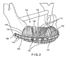
図1〜3に示すように、本発明の第1の例示的な実施形態に係るグラフト格納装置100は、第1の端部104から第2の端部106に長手方向に延び、内部を通って延びる通路108を含む本体102を備えている。本体102は、第1の端部104から第2の端部106に延びる少なくとも1つの螺旋構造体110によって形成されてもよい。装置は、螺旋構造体110の第1のものが装置100の長さの一部のみに沿って延びる一方で第2の構造体110が装置100の長さの全体又は一部に沿って延在するような複数の螺旋構造体を含みうる点は当業者によって理解されるであろう。螺旋構造体110は、装置100の長手方向軸の周りに巻かれて装置100の外周を形成している。構造体110は、通路108を画定する概ね螺旋状の形態で装置100の長手方向軸の周囲に延びている。螺旋状の形態とは、長手方向軸の周りに、長手方向軸に垂直な平面に対してある角度をなして巻かれた構造体110の状態を一般的に指すが、装置100の外周の形状はグラフトで置換される骨の一部分の形状にできるだけ近くなるように規定されるため、装置100の外周の形状が厳密に螺旋状である必要はない点は当業者によって理解されよう。
As shown in FIGS. 1 to 3, the
グラフト格納装置100の本体102は、グラフト格納装置100が骨内の標的空間又は間隙に配置されるときに本体102が骨の外形に実質的に一致するような大きさ及び形状に構成されている。例示的な一実施形態では、本体102は、端部104、106のそれぞれが、骨の分離された部分の端部の対応する一方の外表面の形状に実質的に一致するように、標的骨の2つの分離された部分間に配置されるような大きさ及び形状に構成される。螺旋構造体110は、グラフト格納装置100を、置換される骨の一部分の経路に沿って延びるように、長手方向に圧縮又は伸張及び/又は湾曲させることを可能にする。グラフト材料は、第1及び第2の開放端部104、106から通路108内に挿入することができる。これに代えるか、又はこれに加えて、グラフト材料は、螺旋構造体110の隣り合った巻きの間の空間112から通路108内に挿入してもよいし、グラフト格納装置100が複数の螺旋構造体110を含む場合には、隣り合った螺旋構造体110の間の空間112から挿入してもよい。当業者によって理解されるように、1つ又は2つ以上の螺旋構造体110の隣り合った巻きを互いから離間するように動かすことにより、空間112を拡大することで骨グラフト材料の挿入を容易にすることができる。
The
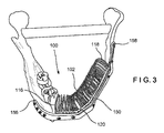
グラフト格納装置100の本体102は第1の端部104から第2の端部106へと長手方向に延び、標的骨、特に下顎骨の外表面の形状に一致した形状を概ね規定する。図1〜3に示される実施形態では、本体102は複数の螺旋構造体110によって形成されており、螺旋構造体110の第1の端部104は、第1の連結構造体116を介して互いに連結され、螺旋構造体110の第2の端部106は、第2の連結構造体118を介して互いに連結されている。螺旋構造体110は、グラフト格納装置110の長手方向軸の周りに延びて通路108を画定している。一実施形態では、本体102は実質的に円筒状であってよく、第1及び第2の連結構造体116、118はリングとして構成することができる。しかしながら、本体102並びに第1及び第2の連結構造体116、118は、グラフト格納装置100が挿入される標的空間の外形に一致する様々な形状のいずれを有してもよい点は当業者には理解されよう。グラフト格納装置100は可撓性材料で形成することができ、これにより、本体102が充填しようとする標的空間の正確な形状でない場合であっても、グラフト格納装置100を曲げて変形させることで所望の標的空間に適合させることができる点もやはり当業者には理解されよう。例えば、グラフト格納装置100は、ポリカプロラクトン(PCL)、ポリラクチド及び/又はチタンなどの材料で形成することができる。
The
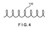
図1〜3は、上記に述べたように、複数の螺旋構造体110からなるグラフト格納装置100を示しているが、図4に示すように、グラフト格納装置100を代わりに単一の螺旋構造体110で形成してもよい。グラフト格納装置100が単一の螺旋構造体110のみを含む場合、第1及び第2の連結構造体116、118は必要ではない。
1 to 3 show a
更なる実施形態では、グラフト格納装置100はまた、本体102の長さの少なくとも一部分に沿って延びる長手方向支柱120を含んでもよい。長手方向支柱120は、本体102の全体又は一部を強化及び/又は補強し、かつ/又は固定要素152を挿入するうえで有用となりうる。例えば、グラフト格納装置100は、骨の分離された部分を整列させるために使用することができる、図2及び図3に示されるような固定プレート150又は他のアタッチメントと共に使用することができる。固定プレート150は、グラフト格納装置100及び骨の分離された部分に固定されることで、骨の分離された部分及び装置100を標的位置に維持するブリッジを形成することができる。固定プレート150は、固定プレートの開口部から隣り合った長手方向支柱120間の空間122に挿入されたねじによってグラフト格納装置100に固定することができる。このため、グラフト格納装置100は少なくとも2本の長手方向支柱120を有する必要がある。例示的な一実施形態では、グラフト格納装置100は4本の長手方向支柱120を含むことができる。しかしながら、グラフト格納装置100は任意の数の長手方向支柱120を含みうる点は当業者には理解されよう。当業者には理解されるように、支柱120はグラフト材料を装置100内に保持する助けとなるように所望のとおりに配置することができる。例えば、骨が片側が下に向いた向きを概ね有する特定の用途では(例えば下顎骨)、重力の影響によって材料が装置100の外に移動することを防止するために支柱120を底部に沿って配置することができる。
In a further embodiment, the graft
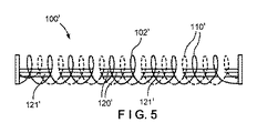
例示的な一実施形態では、長手方向支柱120は本体102の全長に沿って延びる。この実施形態では、長手方向支柱120は、グラフト格納装置100の長さが伸張又は圧縮されることを防止する一方で、本体102を長手方向軸に対して折り曲げる又は屈曲させることは可能にする。別の例示的な実施形態では、図5に示されるように、長手方向支柱120’はグラフト格納装置100’の本体102’の長さに沿って中断していてよく、そのため、装置100’は本体102’の長さに沿って複数の長手方向支柱120’の組121’を含む。長手方向支柱120’の各組121’は、1つ又は2つ以上の螺旋構造体110’の隣り合った複数の巻きに沿って延び、1つ又は2つ以上の螺旋構造体110’の隣り合った複数の巻きによって隣りの組121’の長手方向支柱120’から分離されている。中断した長手方向支柱120’は、グラフト格納装置100’を本体102’の長さに沿った特定の位置で伸張及び/又は圧縮することを可能にする。詳細には、本体102’の長手方向支柱120’が含まれていない部分、すなわち長手方向支柱120’の組121’が互いから離間した部分において、本体102’を伸張及び/又は圧縮させることができる。
In one exemplary embodiment, the
装置100、100’は、長手方向支柱120、120’を、本体102、102’の長さの少なくとも一部分に沿って実質的に直線状(例えば実質的に直線に沿って)延びるものとしてそれぞれ示しているが、支柱は、数多くの形態のいずれかで本体の長さの少なくとも一部分に沿って長手方向に延びてもよい点は当業者には理解されよう。例えば、別の例示的な実施形態によれば、図6及び図7に示すように、上記に述べた装置100、100’と実質的に同様のものとすることができるグラフト格納装置100”の本体102”は、振動する波形形態(例えば、正弦波状)で本体102”に沿って長手方向に延びる複数の支柱120”を含むことができる。支柱120”の波形形態により、本体102”を強化しながら本体102”のすべての軸方向における可撓性を与えることもできる。これにより、図6〜7に示されるように、支柱120”が本体102”の全長に沿って延びている場合であっても、骨の標的空間に適合するように、必要に応じて本体102”を伸張及び/又は圧縮させることができる。上記に述べた装置100、100’と同様、隣り合った支柱120”間に固定要素を挿入することによって固定プレート又は他のアタッチメントをこれに取り付けることができる。支柱120”は本体102”の全長に沿って延びているものとして示されているが、支柱120”は、本体100’と同様、本体の長さに沿って中断していてもよい。
The
例示的な一方法によれば、グラフト格納装置100の通路108は、グラフト格納装置108を標的空間又は標的骨(特に下顎骨)の標的空間又は間隙内に配置するのに先立って、第1及び/又は第2の端部104、106からグラフト材料で充填することができる。上記に述べたように、骨の分離された2つの部分の間に空間又は間隙があってよく、そのため、グラフト格納装置100はこれらの分離された2つの部分同士を連結するブリッジとして機能する。また、グラフト格納装置100を骨の一端において空間内に配置することもでき、その場合グラフト格納装置100の一端のみが骨に接触し、又は、グラフト格納装置100を骨内に形成された凹部内に配置することもでき、その場合、グラフト格納装置100はその3つの面に沿って骨と接触する。以下の例示的な方法では、グラフト格納装置100を使用して骨の分離された部分間の空間を充填することについて述べているが、グラフト格納装置100は骨に形成された様々な空間又は間隙のいずれを充填するために使用することもできる点は当業者には理解されよう。グラフト格納装置100は、必要に応じて、伸張(すなわち、1つ又は2つ以上の螺旋構造体110の隣り合った巻きの間の空間112が大きくなるよう、第1の端部104と第2の端部106とを互いから引き離すことにより長さを大きくする)、圧縮(すなわち、1つ又は2つ以上の螺旋構造体110の隣り合った巻きの間の空間112が小さくなるよう、第1の端部104と第2の端部106とを互いに向かって動かすことにより長さを小さくする)、及び/又は湾曲(すなわちその長手方向軸に沿って曲げる)させることによって、骨の標的空間に適合させることができる。上記に述べたように、長手方向支柱120が本体102の全長に沿って延びている場合には、グラフト格納装置100は標的空間に適合するように曲げるか又は湾曲させるだけでよい。グラフト格納装置100の本体102の長さが標的空間に対して長すぎる場合、外科医又は他の使用者は、本体102を所望の長さに切断することができる。しかしながら、グラフト格納装置100’の長さに沿って中断している長手方向支柱120’は、標的空間に適合するように伸張及び/又は圧縮することができる。同様に、振動する波形形態を有する支柱120”も、必要に応じて伸張、圧縮、及び/又は湾曲させることができる。
According to one exemplary method, the
グラフト格納装置100が標的空間内に配置された後、必要に応じて、更なるグラフト材料を、1つ又は2つ以上の螺旋構造体110の隣り合った螺旋巻き間の空間112から通路108内に充填することができる。その後、グラフト格納装置100を、骨の分離された部分間にブリッジを形成することができるか、及び/又はそれらの部分を整列させることができる固定プレート150又は他のアタッチメントによって骨に固定することができる。固定プレート150は、固定プレート150を貫通する開口部154が長手方向支柱120と実質的に一致するように、グラフト格納装置100の長さに沿って配置することができる。固定プレート150の第1及び第2の端部156、158はグラフト格納装置100の第1及び第2の端部104、106をそれぞれ越えて延びてよく、これにより、固定プレート150の第1及び第2の端部156、158が骨の分離された部分上に延びるため、プレート150をグラフト格納装置100及び骨の分離された部分の両方に固定することができる。詳細には、固定要素152を固定プレート150の開口部154及び隣り合った長手方向支柱120間の空間122を通して挿入することにより、固定プレート150をグラフト格納装置100に固定することができる。同様に、固定要素152を固定プレートの骨上に延びる部分に沿って開口部154を通して挿入することにより、固定プレート150を骨に固定することができる。上記の例示的な方法ではグラフト格納装置100の配置及び使用について述べているが、装置100’及び100”も同様に配置及び使用することができる点は当業者には理解されよう。
After the graft
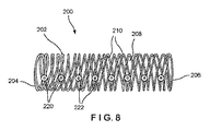
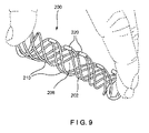
図8〜11に示されるように、グラフト格納装置200は上記に述べたような装置100と実質的に同様のものであってよく、第1の端部204から第2の端部206に延びて長手方向に貫通する通路208を画定する1つ又は2つ以上の螺旋構造体210によって形成されている本体202を備えている。本体202は、装置100に関して上記に述べた本体102と実質的に同様であってよい。しかしながら、グラフト格納装置200は、長手方向支柱の代わりに複数のボタン220を含んでよく、各ボタン220は、1つ又は2つ以上の螺旋構造体210の隣り合った巻き同士を連結している。ボタン220の1つ又は2つ以上のものは、例えば骨ねじなどの骨固定要素のシャフトを受容するための、ボタンを通って延びる開口部222を含むことができ、これにより、固定プレート又は他のアタッチメントをグラフト格納装置200に固定することができる。複数のボタン120のそれぞれは、本体202の長さに沿って互いから離間していてよい。例えば、ボタン220は、螺旋構造体210の隣り合った巻きの間に交互に配置することができる。しかしながら、グラフト格納装置200は、ボタン220のそれぞれが本体202の長さに沿って任意の所望の距離で互いから離間した、任意の数のボタン220を含むことができる。隣接するボタン220間の間隔のため、グラフト格納装置200を伸張(図9に示される)、圧縮(図10に示される)、及び/又は屈曲(図11に示される)させて、標的骨内、又は標的骨の分離された部分間の標的空間を充填することが可能である。グラフト格納装置200は、上記に述べた装置100と実質的に同様の方法で使用することができる。
As shown in FIGS. 8-11, the
グラフト格納装置100、200は、装置100、200の長手方向軸の周りの一方向にその長さに沿って延びる1つ又は2つ以上の螺旋構造体を有するものとして示されているが、本発明に係るグラフト格納装置は、その長手方向軸の周りの反対方向に延びる螺旋構造体を代わりに有することもできる点は当業者に理解されよう。第1の螺旋構造体は第1の方向に長手方向軸の周りに延びてよく、第2の螺旋構造体は第1の方向と反対の第2の方向に長手方向軸の周りに延びることができる。
Although the
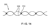
例えば、図12〜14に示されるように、グラフト格納装置300は上記に述べたような装置100、200と実質的に同様のものであってよく、第1の端部304から第2の端部306に延びて通路308を画定する螺旋構造体310によって形成されている本体302を備えている。しかしながら、第1の螺旋構造体310aが本体302の長手方向軸の周りに第1の方向に延びているのに対して、第2の螺旋構造体310bは長手軸の周りに第1の方向の反対の第2の方向に延びており、すなわち、第1及び第2の構造体310、320の螺旋の角度は傾斜して、それらが交差する点でV字形状を形成している。装置100、200と同様、螺旋構造体310の第1の端部304同士は、例えばリングとして構成することができる第1の連結構造体316を介して互いに連結することができる。螺旋構造体310の第2の端部306同士は、例えばリングとして構成することができる第2の連結構造体318を介して互いに連結することができる。グラフト格納装置300は2個の螺旋構造体310で構成されるものとして示され、説明されているが、グラフト格納装置300は、螺旋構造体310のうちの少なくとも2つが本体302の長さに沿って互いに反対方向に延びている限り、必要に応じて、2個よりも多い螺旋構造体310を含むことができる点は当業者には理解されよう。
For example, as shown in FIGS. 12-14, the
例示的な一実施形態では、図13に示されるように、複数の螺旋構造体310は自由に延びており、螺旋構造体310同士はそれぞれ、第1及び第2の端部304、306において第1及び第2の連結構造体316、318によって連結されている以外は互いに連結されていない。別の例示的な実施形態では、図14に示されるように、螺旋構造体310同士は、第1の螺旋構造体310aと第2の螺旋構造体310bとが互いに交差する1つ又は2つ以上の点314において連結されてもよい。螺旋構造体310同士は、各交点314で連結されてもよいし、あるいは必要に応じて特定の交点314で連結されてもよい。
In one exemplary embodiment, as shown in FIG. 13, the plurality of
図には示されていないが、グラフト格納装置300は例えば、装置100に関して上記に述べた長手方向支柱120又は装置200に関して上記に述べたボタン220のような、固定要素を受容するための構造体又は機構を含んでもよい点は当業者には理解されよう。例示的な一実施形態では、ボタン220が交点314において連結部として機能してもよい。
Although not shown in the figure, the graft
例えば、図15〜16に示されるように、本発明の別の例示的実施形態に係る装置400は上記に述べたような装置100〜300と実質的に同様のものであってよく、第1の端部404から第2の端部406に延びて通路408を画定する螺旋構造体410によって形成されている本体404を備えている。しかしながら、螺旋構造体410は、波形形態411を有する部分を含むことができる。波形形態411は、螺旋構造体410の部分に沿って本体402の片側に沿って延びることができる。あるいは、波形形態411は、螺旋構造体410の全体に沿って延びていてもよい。
For example, as shown in FIGS. 15-16, the
波形形態411は、通路408内に受容されるグラフト材料のより効果的な保持を与えることができる。加えて、波形形態411は、グラフト格納装置400が圧縮されるときに互いに噛み合い、グラフト格納装置400に剛性を与えることができる。螺旋構造体410は、波形形態の部分が噛み合っている場合でも、隣り合った巻き同士を互いから離れるように動かしてその間の空間412を広げることにより、螺旋構造体410の隣り合った巻きの間の空間412から通路408内にグラフト材料を充填することができるように構成されている。
本発明の趣旨又は範囲から逸脱することなく本発明の構造及び方法に様々な改変及び変更を行うことが可能である点は当業者であれば理解されるであろう。したがって、本発明の改変及び変更が、添付の特許請求の範囲及びその均等物の範囲内に含まれるものであれば、本発明はそれらを包含するものとする。 Those skilled in the art will appreciate that various modifications and changes can be made to the structure and methods of the present invention without departing from the spirit or scope of the present invention. Therefore, if the modifications and modifications of the present invention are included within the scope of the appended claims and their equivalents, the present invention shall include them.
〔実施の態様〕
(1) 骨グラフト格納装置であって、
本体であって、該本体の長手方向軸の周りに第1の端部から第2の端部に延びて前記本体を長手方向に貫通して延びる通路を画定する1つ又は2つ以上の螺旋構造体によって形成されている、本体を備え、前記通路がその内部に骨グラフト材料を受容するように構成され、前記1つ又は2つ以上の螺旋構造体は、標的骨の標的空間を充填するために前記本体が伸張、圧縮、及び湾曲のいずれかを行うことを可能にする材料で形成されている、骨グラフト格納装置。
(2) 前記1つ又は2つ以上の螺旋構造体の少なくとも2つの隣り合った巻き同士を連結する固定要素受容構造体を更に備える、実施態様1に記載の装置。
(3) 前記固定要素受容構造体が、前記本体の長さの少なくとも一部分に沿って延びる長手方向支柱であり、隣り合った長手方向支柱間の間隔が、固定要素のシャフトを受容するように構成されている、実施態様2に記載の装置。
(4) 前記長手方向支柱が前記本体の前記長さに沿って中断していることにより、前記長手方向支柱が前記本体の前記長さに沿った長手方向支柱の複数の組に分割されている、実施態様3に記載の装置。
(5) 前記長手方向支柱が、直線状形態及び振動する波形形態のいずれかで前記本体の前記長さに沿って延びる、実施態様3に記載の装置。
[Implementation mode]
(1) Bone graft storage device
A body, one or more spirals defining a passage extending longitudinally through the body extending from a first end to a second end around the longitudinal axis of the body. It comprises a body formed by a structure, the passage is configured to receive bone graft material within it, and the one or more helical structures fill the target space of the target bone. A bone graft containment device made of a material that allows the body to be stretched, compressed, or curved.
(2) The apparatus according to embodiment 1, further comprising a fixed element receiving structure that connects at least two adjacent windings of the one or more spiral structures.
(3) The fixed element receiving structure is a longitudinal column extending along at least a part of the length of the main body, and the distance between adjacent longitudinal columns is configured to receive the shaft of the fixed element. The device according to the second embodiment.
(4) Since the longitudinal column is interrupted along the length of the main body, the longitudinal column is divided into a plurality of sets of the longitudinal columns along the length of the main body. , The apparatus according to the third embodiment.
(5) The apparatus according to the third embodiment, wherein the longitudinal column extends along the length of the main body in either a linear form or a vibrating corrugated form.
(6) 前記固定要素受容構造体がボタンであり、各ボタンは前記1つ又は2つ以上の螺旋構造体の隣り合った巻き同士を連結し、固定要素のシャフトを受容するための、前記各ボタンを通って延びる開口部を含み、各ボタンは前記本体の長さに沿ったある距離によって、隣接するボタンから離間している、実施態様2に記載の装置。
(7) 前記本体が、少なくとも2つの螺旋構造体によって形成されている、実施態様1に記載の装置。
(8) 前記少なくとも2つの螺旋構造体の前記第1の端部を連結する第1の連結構造体と、前記少なくとも2つの螺旋構造体の前記第2の端部を連結する第2の連結構造体と、を更に備える、実施態様7に記載の装置。
(9) 前記少なくとも2つの螺旋構造体のうちの第1のものが前記本体の前記長手方向軸の周りの第1の方向に延び、前記少なくとも2つの螺旋構造体のうちの第2のものが前記本体の前記長手方向軸の周りの第2の方向に延び、前記第2の方向が前記第1の方向と反対である、実施態様7に記載の装置。
(10) 前記第1の螺旋構造体と前記第2の螺旋構造体とは、前記第1の螺旋構造体と前記第2の螺旋構造体とが互いに交差する点において互いに連結されている、実施態様9に記載の装置。
(6) The fixed element receiving structure is a button, and each button connects adjacent windings of the one or more spiral structures to each other to receive the shaft of the fixed element. 2. The device of embodiment 2, wherein each button is separated from an adjacent button by a distance along the length of the body, including an opening extending through the buttons.
(7) The apparatus according to the first embodiment, wherein the main body is formed of at least two spiral structures.
(8) A first connecting structure that connects the first ends of the at least two spiral structures and a second connecting structure that connects the second ends of the at least two spiral structures. The device according to embodiment 7, further comprising a body.
(9) The first of the at least two spiral structures extends in the first direction around the longitudinal axis of the body, and the second of the at least two spiral structures 7. The apparatus of embodiment 7, wherein the main body extends in a second direction around the longitudinal axis and the second direction is opposite to the first direction.
(10) The first spiral structure and the second spiral structure are connected to each other at a point where the first spiral structure and the second spiral structure intersect with each other. The device according to aspect 9.
(11) 前記1つ又は2つ以上の螺旋構造体がその長さの少なくとも一部分に沿った波形形態を有することにより、前記本体が圧縮されているときに、前記1つ又は2つ以上の螺旋構造体の隣り合った巻きの前記波形形態が互いに噛み合う、実施態様1に記載の装置。
(12) 前記波形形態が、前記本体の片側に沿って延びる、実施態様11に記載の装置。
(13) 前記1つ又は2つ以上の螺旋構造体が、実質的に円筒状の形状を画定する、実施態様1に記載の装置。
(14) 前記1つ又は2つ以上の螺旋構造体が前記長手方向軸に垂直な平面に対してある角度をなして前記長手方向軸の周りに延びることにより、前記本体の形状が、充填される前記標的空間の形状に一致する、実施態様1に記載の装置。
(15) 骨グラフトシステムであって、
グラフト格納装置であって、本体であって、該本体の長手方向軸の周りに第1の端部から第2の端部に延びて前記本体を長手方向に貫通して延びる通路を画定する1つ又は2つ以上の螺旋構造体によって形成されている、本体を含み、前記通路がその内部に骨グラフト材料を受容するように構成され、前記1つ又は2つ以上の螺旋構造体は、標的骨の標的空間を充填するために前記本体が伸張、圧縮、及び湾曲のいずれかを行うことを可能にする材料で形成されている、グラフト格納装置と、
前記グラフト格納装置を前記骨に取り付けるために前記グラフト格納装置の長さに沿って配置されるような大きさ及び形状に構成された固定プレートであって、アタッチメントは、内部を通して固定要素を受容するための、前記アタッチメントを通って延びる開口部を含む、固定プレートと、を備える、骨グラフトシステム。
(11) The one or more helices when the body is compressed by having the one or more helix structures have a corrugated form along at least a portion of their length. The apparatus according to embodiment 1, wherein the corrugated forms of adjacent windings of a structure mesh with each other.
(12) The apparatus according to embodiment 11, wherein the waveform form extends along one side of the main body.
(13) The apparatus according to embodiment 1, wherein the one or more spiral structures define a substantially cylindrical shape.
(14) The shape of the main body is filled by extending the one or more spiral structures around the longitudinal axis at an angle to a plane perpendicular to the longitudinal axis. The device according to embodiment 1, which matches the shape of the target space.
(15) Bone graft system
A graft storage device, the main body, defining a passage extending from the first end to the second end around the longitudinal axis of the main body and extending longitudinally through the main body 1. The passage is configured to receive bone graft material within it, including the body, which is formed by one or more helical structures, wherein the one or more helical structures are targets. With a graft containment device, the body is made of a material that allows it to stretch, compress, or bend to fill the target space of the bone.
A fixation plate configured in size and shape such that the graft retractor is placed along the length of the graft retractor to attach to the bone, the attachment receiving the fixation element through the interior. Bone graft system, comprising a fixation plate, comprising an opening extending through the attachment for use.
(16) 前記グラフト格納装置が、前記1つ又は2つ以上の螺旋構造体の少なくとも2つの隣り合った巻き同士を連結する固定要素受容構造体を更に含む、実施態様15に記載のシステム。
(17) 前記固定要素受容構造体が、前記本体の長さの少なくとも一部分に沿って延びる長手方向支柱であり、隣り合った長手方向支柱間の間隔が、固定要素のシャフトを受容するように構成されている、実施態様16に記載のシステム。
(18) 前記固定要素受容構造体がボタンであり、各ボタンは前記1つ又は2つ以上の螺旋構造体の隣り合った巻き同士を連結し、固定要素のシャフトを受容するための、前記各ボタンを通って延びる開口部を含み、各ボタンは前記本体の長さに沿ったある距離によって、隣接するボタンから離間している、実施態様16に記載のシステム。
(19) 第1の螺旋構造体が前記本体の前記長手方向軸の周りの第1の方向に延び、第2の螺旋構造体が前記本体の前記長手方向軸の周りの第2の方向に延び、前記第2の方向が前記第1の方向と反対である、実施態様15に記載のシステム。
(20) 前記1つ又は2つ以上の螺旋構造体がその長さの少なくとも一部分に沿った波形形態を有することにより、前記本体が圧縮されているときに、前記1つ又は2つ以上の螺旋構造体の隣り合った巻きの前記波形形態が互いに噛み合う、実施態様15に記載のシステム。
(16) The system of embodiment 15, wherein the graft accommodating device further comprises a fixed element accepting structure that connects at least two adjacent windings of the one or more helical structures.
(17) The fixed element receiving structure is a longitudinal strut extending along at least a portion of the length of the body, and the spacing between adjacent longitudinal columns is configured to receive the shaft of the fixed element. 16. The system according to embodiment 16.
(18) The fixed element receiving structure is a button, and each button connects adjacent windings of the one or more spiral structures to each other to receive the shaft of the fixed element. 16. The system of embodiment 16, wherein each button is separated from an adjacent button by a distance along the length of the body, including an opening extending through the buttons.
(19) A first spiral structure extends in a first direction around the longitudinal axis of the body and a second spiral structure extends in a second direction around the longitudinal axis of the body. , The system according to embodiment 15, wherein the second direction is opposite to the first direction.
(20) The one or more helices when the body is compressed by having the one or more helix structures have a corrugated form along at least a portion of their length. The system according to embodiment 15, wherein the corrugated forms of adjacent windings of a structure mesh with each other.
Claims (21)
本体であって、該本体の長手方向軸の周りに第1の端部から第2の端部に延びて前記本体を長手方向に貫通して延びる通路を螺旋内に画定する1つ又は2つ以上の螺旋構造体によって形成されている、本体を備え、前記通路がその内部に骨グラフト材料を受容するように構成され、前記1つ又は2つ以上の螺旋構造体は、標的骨の標的空間を充填するために前記本体が伸張及び湾曲のいずれかを行うことを可能にする材料で形成されており、前記本体における複数の開口は、前記複数の開口を通じて前記本体内に骨グラフト材料を充填可能なサイズになっている、骨グラフト格納装置。 Bone graft storage device
One or two main bodies, one or two spirally defined passages extending from the first end to the second end around the longitudinal axis of the main body and extending longitudinally through the main body. The main body, said passage is configured to receive bone graft material within it, which is formed by the above helical structures, the one or more helical structures being the target space of the target bone. The body is made of a material that allows the body to be stretched or curved to fill the body, and the plurality of openings in the body fill the body with bone graft material through the plurality of openings. Bone graft retractor, sized to be possible.
グラフト格納装置であって、本体であって、該本体の長手方向軸の周りに第1の端部から第2の端部に延びて前記本体を長手方向に貫通して延びる通路を螺旋内に画定する1つ又は2つ以上の螺旋構造体によって形成されている、本体を含み、前記通路がその内部に骨グラフト材料を受容するように構成され、前記1つ又は2つ以上の螺旋構造体は、標的骨の標的空間を充填するために前記本体が伸張及び湾曲のいずれかを行うことを可能にする材料で形成されている、グラフト格納装置と、
前記グラフト格納装置を前記骨に取り付けるために前記グラフト格納装置の長さに沿って配置されるような大きさ及び形状に構成された固定プレートであって、アタッチメントは、内部を通して固定要素を受容するための、前記アタッチメントを通って延びる開口部を含む、固定プレートと、を備え、
前記本体における複数の開口は、前記複数の開口を通じて前記本体内に骨グラフト材料を充填可能なサイズになっている、骨グラフトシステム。 Bone graft system
A graft accommodating device, the main body, spirally having a passage extending from the first end to the second end around the longitudinal axis of the main body and extending longitudinally through the main body. The one or more helical structures comprising the body, the passage being configured to receive bone graft material within it, formed by one or more helical structures defining. With a graft containment device, the body of which is made of a material that allows either stretching or bending to fill the target space of the target bone.
A fixation plate configured in size and shape such that the graft retractor is placed along the length of the graft retractor to attach to the bone, the attachment receiving the fixation element through the interior. A fixed plate, including an opening extending through the attachment, for
A bone graft system in which the plurality of openings in the body are sized so that the body can be filled with bone graft material through the plurality of openings.
Applications Claiming Priority (3)
| Application Number | Priority Date | Filing Date | Title |
|---|---|---|---|
| US201662288273P | 2016-01-28 | 2016-01-28 | |
| US62/288,273 | 2016-01-28 | ||
| PCT/US2017/014029 WO2017132039A1 (en) | 2016-01-28 | 2017-01-19 | Helical bone graft containment cage |
Publications (3)
| Publication Number | Publication Date |
|---|---|
| JP2019503248A JP2019503248A (en) | 2019-02-07 |
| JP2019503248A5 JP2019503248A5 (en) | 2020-02-27 |
| JP6976956B2 true JP6976956B2 (en) | 2021-12-08 |
Family
ID=57995273
Family Applications (1)
| Application Number | Title | Priority Date | Filing Date |
|---|---|---|---|
| JP2018539272A Active JP6976956B2 (en) | 2016-01-28 | 2017-01-19 | Spiral bone graft storage cage |
Country Status (8)
| Country | Link |
|---|---|
| US (1) | US11478356B2 (en) |
| EP (1) | EP3407837B1 (en) |
| JP (1) | JP6976956B2 (en) |
| CN (1) | CN108601658A (en) |
| AU (1) | AU2017211022B2 (en) |
| BR (1) | BR112018014553A2 (en) |
| CA (1) | CA3012442A1 (en) |
| WO (1) | WO2017132039A1 (en) |
Families Citing this family (16)
| Publication number | Priority date | Publication date | Assignee | Title |
|---|---|---|---|---|
| WO2016176496A1 (en) | 2015-04-29 | 2016-11-03 | Institute for Musculoskeletal Science and Education, Ltd. | Coiled implants and systems and methods of use thereof |
| US10449051B2 (en) | 2015-04-29 | 2019-10-22 | Institute for Musculoskeletal Science and Education, Ltd. | Implant with curved bone contacting elements |
| US10492921B2 (en) | 2015-04-29 | 2019-12-03 | Institute for Musculoskeletal Science and Education, Ltd. | Implant with arched bone contacting elements |
| DE102015106861A1 (en) | 2015-05-04 | 2016-11-10 | Espera-Werke Gmbh | Device for labeling individual products |
| EP3407836B1 (en) * | 2016-01-28 | 2021-05-05 | DePuy Synthes Products, Inc. | Splitting attachment for graft containment cage |
| US10512549B2 (en) * | 2017-03-13 | 2019-12-24 | Institute for Musculoskeletal Science and Education, Ltd. | Implant with structural members arranged around a ring |
| US10357377B2 (en) | 2017-03-13 | 2019-07-23 | Institute for Musculoskeletal Science and Education, Ltd. | Implant with bone contacting elements having helical and undulating planar geometries |
| US10357367B2 (en) * | 2017-09-11 | 2019-07-23 | DePuy Synthes Products, Inc. | Patient-specific mandible graft cage |
| US10932912B2 (en) | 2017-09-11 | 2021-03-02 | DePuy Synthes Products, Inc. | Plug in struts for graft cage |
| US10744001B2 (en) | 2017-11-21 | 2020-08-18 | Institute for Musculoskeletal Science and Education, Ltd. | Implant with improved bone contact |
| US10940015B2 (en) | 2017-11-21 | 2021-03-09 | Institute for Musculoskeletal Science and Education, Ltd. | Implant with improved flow characteristics |
| CN109492887B (en) * | 2018-10-25 | 2021-10-26 | 浙江工商大学 | Mobile crowd sensing and exciting method based on potential game theory |
| KR101996849B1 (en) * | 2018-12-26 | 2019-10-01 | (주)메디쎄이 | Patient-tailored mandibular implants and methods for manufacturing the same |
| TWI716156B (en) | 2019-10-18 | 2021-01-11 | 財團法人工業技術研究院 | Mandibular reconstruction prosthesis |
| US11504240B2 (en) | 2020-06-04 | 2022-11-22 | DePuy Synthes Products, Inc. | Modular bone graft cage |
| CN116747051B (en) * | 2023-08-22 | 2023-11-24 | 北京大学第三医院(北京大学第三临床医学院) | Bone implant |
Family Cites Families (23)
| Publication number | Priority date | Publication date | Assignee | Title |
|---|---|---|---|---|
| US4787906A (en) * | 1987-03-02 | 1988-11-29 | Haris Andras G | Controlled tissue growth and graft containment |
| US6989033B1 (en) * | 1992-09-17 | 2006-01-24 | Karlheinz Schmidt | Implant for recreating verterbrae and tubular bones |
| DE4409836A1 (en) * | 1994-03-22 | 1995-09-28 | Draenert Klaus | Device for the mechanical protection of an implant or graft when inserted into and / or remaining in a living body |
| US6280473B1 (en) * | 1996-08-19 | 2001-08-28 | Macropore, Inc. | Resorbable, macro-porous, non-collapsing and flexible membrane barrier for skeletal repair and regeneration |
| US6149651A (en) * | 1997-06-02 | 2000-11-21 | Sdgi Holdings, Inc. | Device for supporting weak bony structures |
| US7553329B2 (en) * | 1999-08-18 | 2009-06-30 | Intrinsic Therapeutics, Inc. | Stabilized intervertebral disc barrier |
| US6447543B1 (en) * | 1999-09-28 | 2002-09-10 | Sulzer Orthopedics Ltd. | Basket-like container for implanting bone tissue |
| JP2003165761A (en) * | 2001-11-29 | 2003-06-10 | Kinki Concrete Industry Co Ltd | Roofing soil composition |
| US7887587B2 (en) * | 2004-06-04 | 2011-02-15 | Synthes Usa, Llc | Soft tissue spacer |
| CN103999129B (en) * | 2011-12-14 | 2017-04-05 | 斯泰克欧洲控股一有限责任公司 | For generating the technology of bone plate designs |
| US8485820B1 (en) * | 2011-12-22 | 2013-07-16 | Mohamed Ikbal Ali | Devices and methods for enhancing bone growth |
| JP6062150B2 (en) * | 2012-02-14 | 2017-01-18 | 株式会社ハイレックスコーポレーション | Bone defect filling material |
| TW201240653A (en) * | 2012-05-30 | 2012-10-16 | Ossaware Biotech Co Ltd | Hollow-grid medical implant |
| US9936991B2 (en) * | 2015-01-30 | 2018-04-10 | Union Surgical, Llc | Bone fracture treatment apparatus and method |
| US9706294B2 (en) * | 2015-03-18 | 2017-07-11 | Infineon Technologies Ag | System and method for an acoustic transducer and environmental sensor package |
| US9925046B2 (en) * | 2015-03-31 | 2018-03-27 | DePuy Synthes Products, Inc. | Bone graft cage |
| WO2016176496A1 (en) * | 2015-04-29 | 2016-11-03 | Institute for Musculoskeletal Science and Education, Ltd. | Coiled implants and systems and methods of use thereof |
| GB201609448D0 (en) | 2015-09-10 | 2016-07-13 | Obl S A | Medical device |
| DE102015226063A1 (en) * | 2015-12-18 | 2017-06-22 | Aesculap Ag | Medical product and medical kit for use in the treatment, in particular for use in filling and / or closure, a bone cavity |
| US10695181B2 (en) * | 2016-02-16 | 2020-06-30 | DePuy Synthes Products, Inc. | Bone graft cage |
| AU2018215359A1 (en) * | 2017-02-06 | 2019-08-01 | DePuy Synthes Products, Inc. | Bendable graft containment cage |
| US10357367B2 (en) * | 2017-09-11 | 2019-07-23 | DePuy Synthes Products, Inc. | Patient-specific mandible graft cage |
| US10932912B2 (en) * | 2017-09-11 | 2021-03-02 | DePuy Synthes Products, Inc. | Plug in struts for graft cage |
-
2017
- 2017-01-19 CN CN201780008874.3A patent/CN108601658A/en active Pending
- 2017-01-19 WO PCT/US2017/014029 patent/WO2017132039A1/en active Application Filing
- 2017-01-19 EP EP17704122.5A patent/EP3407837B1/en active Active
- 2017-01-19 BR BR112018014553A patent/BR112018014553A2/en active Search and Examination
- 2017-01-19 JP JP2018539272A patent/JP6976956B2/en active Active
- 2017-01-19 CA CA3012442A patent/CA3012442A1/en active Pending
- 2017-01-19 AU AU2017211022A patent/AU2017211022B2/en not_active Ceased
- 2017-01-20 US US15/411,499 patent/US11478356B2/en active Active
Also Published As
| Publication number | Publication date |
|---|---|
| US11478356B2 (en) | 2022-10-25 |
| EP3407837A1 (en) | 2018-12-05 |
| CA3012442A1 (en) | 2017-08-03 |
| WO2017132039A1 (en) | 2017-08-03 |
| JP2019503248A (en) | 2019-02-07 |
| AU2017211022A1 (en) | 2018-06-28 |
| BR112018014553A2 (en) | 2018-12-11 |
| US20170216034A1 (en) | 2017-08-03 |
| EP3407837B1 (en) | 2021-07-07 |
| AU2017211022B2 (en) | 2021-05-20 |
| CN108601658A (en) | 2018-09-28 |
Similar Documents
| Publication | Publication Date | Title |
|---|---|---|
| JP6976956B2 (en) | Spiral bone graft storage cage | |
| JP6953520B2 (en) | Bone graft cage | |
| JP2017060863A5 (en) | Device for stabilizing bone | |
| CA2587439A1 (en) | Devices for introduction into a body via a substantially straight conduit to form a predefined curved configuration, and methods employing such devices | |
| US20080312694A1 (en) | Dynamic stabilization rod for spinal implants and methods for manufacturing the same | |
| JP2019503248A5 (en) | ||
| TWI630900B (en) | Intramedullary fixation system | |
| US11213395B2 (en) | Bendable graft containment cage | |
| JP2014513583A5 (en) | ||
| US20170231767A1 (en) | Bone Graft Cage | |
| JP2020508796A5 (en) | ||
| JP2018512233A (en) | Bone graft cage | |
| RU2377961C1 (en) | Transpedicular vertebral fixation technique | |
| EP3422971B1 (en) | Bracket for external fixation of bones | |
| JP6852201B2 (en) | Lockable web plate | |
| US9936991B2 (en) | Bone fracture treatment apparatus and method | |
| JP6190994B2 (en) | Medical linear members for bone healing | |
| JP2007289551A (en) | Bone prosthesis | |
| US20190201061A1 (en) | Expandable orthopedic implant | |
| KR101708859B1 (en) | Stent | |
| US20210121212A1 (en) | Flexible Connecting Rod for Industrial Applications | |
| RU48748U1 (en) | DEVICE FOR EXTERNAL FIXING OF FINGERS OF BRUSH | |
| RU24365U1 (en) | BONE FRAGMENT LOCK | |
| RU2003107811A (en) | METHOD FOR OSTEOSYNTHESIS OF FRACTURES OF LONG TUBULAR BONES |
Legal Events
| Date | Code | Title | Description |
|---|---|---|---|
| A521 | Request for written amendment filed |
Free format text: JAPANESE INTERMEDIATE CODE: A523 Effective date: 20200115 |
|
| A621 | Written request for application examination |
Free format text: JAPANESE INTERMEDIATE CODE: A621 Effective date: 20200115 |
|
| A131 | Notification of reasons for refusal |
Free format text: JAPANESE INTERMEDIATE CODE: A131 Effective date: 20201117 |
|
| A977 | Report on retrieval |
Free format text: JAPANESE INTERMEDIATE CODE: A971007 Effective date: 20201118 |
|
| A521 | Request for written amendment filed |
Free format text: JAPANESE INTERMEDIATE CODE: A523 Effective date: 20210212 |
|
| A131 | Notification of reasons for refusal |
Free format text: JAPANESE INTERMEDIATE CODE: A131 Effective date: 20210629 |
|
| A601 | Written request for extension of time |
Free format text: JAPANESE INTERMEDIATE CODE: A601 Effective date: 20210929 |
|
| A521 | Request for written amendment filed |
Free format text: JAPANESE INTERMEDIATE CODE: A523 Effective date: 20211012 |
|
| TRDD | Decision of grant or rejection written | ||
| A01 | Written decision to grant a patent or to grant a registration (utility model) |
Free format text: JAPANESE INTERMEDIATE CODE: A01 Effective date: 20211026 |
|
| A61 | First payment of annual fees (during grant procedure) |
Free format text: JAPANESE INTERMEDIATE CODE: A61 Effective date: 20211110 |
|
| R150 | Certificate of patent or registration of utility model |
Ref document number: 6976956 Country of ref document: JP Free format text: JAPANESE INTERMEDIATE CODE: R150 |