JP6972089B2 - Image processing equipment, image processing methods, and programs - Google Patents
Image processing equipment, image processing methods, and programs Download PDFInfo
- Publication number
- JP6972089B2 JP6972089B2 JP2019224688A JP2019224688A JP6972089B2 JP 6972089 B2 JP6972089 B2 JP 6972089B2 JP 2019224688 A JP2019224688 A JP 2019224688A JP 2019224688 A JP2019224688 A JP 2019224688A JP 6972089 B2 JP6972089 B2 JP 6972089B2
- Authority
- JP
- Japan
- Prior art keywords
- coordinate
- transformation
- linear
- conversion
- coordinates
- Prior art date
- Legal status (The legal status is an assumption and is not a legal conclusion. Google has not performed a legal analysis and makes no representation as to the accuracy of the status listed.)
- Active
Links
- 238000012545 processing Methods 0.000 title claims description 41
- 238000003672 processing method Methods 0.000 title claims 3
- 230000009466 transformation Effects 0.000 claims description 188
- 238000006243 chemical reaction Methods 0.000 claims description 136
- 238000000034 method Methods 0.000 claims description 63
- 230000008569 process Effects 0.000 claims description 51
- 230000002194 synthesizing effect Effects 0.000 claims description 16
- PXFBZOLANLWPMH-UHFFFAOYSA-N 16-Epiaffinine Natural products C1C(C2=CC=CC=C2N2)=C2C(=O)CC2C(=CC)CN(C)C1C2CO PXFBZOLANLWPMH-UHFFFAOYSA-N 0.000 claims description 15
- 238000000844 transformation Methods 0.000 claims description 12
- 230000015572 biosynthetic process Effects 0.000 claims description 11
- 238000003786 synthesis reaction Methods 0.000 claims description 11
- 230000006870 function Effects 0.000 claims description 7
- 230000001131 transforming effect Effects 0.000 claims 2
- 238000012937 correction Methods 0.000 description 31
- 238000000354 decomposition reaction Methods 0.000 description 9
- 238000010586 diagram Methods 0.000 description 6
- 238000012986 modification Methods 0.000 description 4
- 230000004048 modification Effects 0.000 description 4
- 230000009467 reduction Effects 0.000 description 4
- 238000013507 mapping Methods 0.000 description 3
- 238000013519 translation Methods 0.000 description 3
- 230000000694 effects Effects 0.000 description 2
- 238000010521 absorption reaction Methods 0.000 description 1
- 230000006866 deterioration Effects 0.000 description 1
- 230000005484 gravity Effects 0.000 description 1
- 238000002156 mixing Methods 0.000 description 1
- 230000003287 optical effect Effects 0.000 description 1
Images


Landscapes
- Image Processing (AREA)
Description
本発明は、2次元座標位置に応じて記録されたデータに幾何変換を実行する技術に関するものである。 The present invention relates to a technique for performing geometric transformation on data recorded according to a two-dimensional coordinate position.
従来、デジタルカメラやプリンタ、プロジェクタなどデジタル画像を扱う機器では、デジタル画像に座標変換による幾何変換処理がしばしば実行されている。例えば、プリンタでは印刷の解像度に合わせて入力画像の拡大処理(高解像度化処理)が行われている。監視カメラでは、被写体に向かって斜め方向から撮影する場合に、建物などの長方形の被写体が台形に歪むため台形を長方形となるよう補正すること(パースペクティブ補正)や、画像内の注目領域を拡大処理することなどがある。プロジェクタでは投影画像を投影面に合わせるようキーストーン補正処理などが行われている。幾何変換処理において、拡大縮小、回転、スキュー及び平行移動といった線形な座標変換を線形変換、それ以外の座標変換を非線形変換と呼ぶこととする。 Conventionally, in devices that handle digital images such as digital cameras, printers, and projectors, geometric transformation processing by coordinate transformation is often executed for digital images. For example, in a printer, an enlargement process (high resolution process) of an input image is performed according to a print resolution. With a surveillance camera, when shooting from an oblique direction toward the subject, a rectangular subject such as a building is distorted into a trapezoid, so the trapezoid is corrected to be rectangular (perspective correction), and the area of interest in the image is enlarged. There are things to do. In the projector, keystone correction processing is performed so that the projected image is aligned with the projection surface. In the geometric transformation process, linear coordinate transformations such as enlargement / reduction, rotation, skew and translation are called linear transformations, and other coordinate transformations are called non-linear transformations.
幾何変換処理は高速化のためにしばしばハードウェアで実装される。線形変換は比較的少ない演算リソースで実装可能であるが、非線形変換は除算など複雑な演算が必要になるため、回路規模が大きくなるという課題がある。特に近年の画像の高解像度化(8Kなど)に伴って座標の取り得る値域も拡大しており、高精度な座標変換の実現のためには大規模な演算回路などが必要となっている。 Geometric transformations are often implemented in hardware for speed. Linear transformation can be implemented with relatively few arithmetic resources, but nonlinear transformation requires complicated operations such as division, so there is a problem that the circuit scale becomes large. In particular, with the recent increase in image resolution (8K, etc.), the range in which coordinates can be obtained has expanded, and a large-scale arithmetic circuit or the like is required to realize highly accurate coordinate conversion.
そこで、例えば特許文献1では、まず画像を複数の三角形領域に分割する。そして、分割された領域ごとに頂点の対応からアフィン変換(線形変換)を行う。これにより、画像全体では所望の非線形変換を近似した変換を実現している。また、特許文献2では、X線診断装置において全撮影角度に対応する歪み補正のための補正テーブルをあらかじめメモリに用意しておく。必要に応じて現在の撮影角度に対応する補正テーブルをアドレス発生器にセットすることで非線形変換を実現している。
Therefore, for example, in Patent Document 1, the image is first divided into a plurality of triangular regions. Then, affine transformation (linear transformation) is performed from the correspondence of the vertices for each divided region. As a result, a transformation that approximates the desired nonlinear transformation is realized for the entire image. Further, in
しかしながら、上記特許文献1に記載の手法では、領域ごとにアフィン変換用のパラメータを設定する必要があり、パラメータの算出自体が煩雑になる。また、領域の境界における不整合により画質劣化を引き起こす可能性がある。上記特許文献2に記載の手法はX線診断装置など撮影角度が限定されている機器では有効であるが、一般的なカメラなど撮影角度の自由度が高い機器では全撮影角度に対応する補正テーブルを用意しておくことは現実的でない。
However, in the method described in Patent Document 1, it is necessary to set parameters for affine transformation for each region, and the calculation of the parameters itself becomes complicated. In addition, inconsistency at the boundaries of the area may cause deterioration of image quality. The method described in
本発明は以上の状況に鑑みてなされたものであって、比較的少ない演算リソースで高精度な幾何変換を実現することを目的とする。 The present invention has been made in view of the above circumstances, and an object of the present invention is to realize highly accurate geometric transformation with relatively few arithmetic resources.
本発明に係る画像処理装置は、2次元座標位置に応じて記録されたデータに幾何変換を行う画像処理装置であって、第1の座標から第2の座標への変換処理を、前記第1の座標から第3の座標に変換する線形変換の結果と、前記第1の座標から第4の座標に変換する非線形変換の結果との合成になるようにするために、前記線形変換及び前記非線形変換の変換パラメータを決定する制御手段と、前記線形変換の変換パラメータに基づく前記線形変換で前記第3の座標を算出する線形変換手段と、前記非線形変換の変換パラメータに基づく前記非線形変換で、前記第4の座標を算出する非線形変換手段と、前記第3の座標と前記第4の座標を合成して、前記第2の座標を算出する合成手段とを有することを特徴とする。 The image processing apparatus according to the present invention is an image processing apparatus that performs geometric transformation to the recorded data according to the two-dimensional coordinate position, the conversion process from the first coordinate to a second coordinate, the first In order to combine the result of the linear transformation that transforms from the first coordinate to the third coordinate and the result of the nonlinear transformation that transforms from the first coordinate to the fourth coordinate, the linear transformation and the nonlinear control means for determining the transformation parameters of the transformation, and linear transformation means for calculating said third coordinate in the linear conversion based on the conversion parameter of the linear transformation, with the non-linear conversion based on the conversion parameter of the non-linear transformation, the It is characterized by having a non-linear transformation means for calculating a fourth coordinate and a synthesis means for synthesizing the third coordinate and the fourth coordinate to calculate the second coordinate.
本発明によれば、高精度な幾何変換を比較的少ない演算リソースで実現できる。 According to the present invention, highly accurate geometric transformation can be realized with relatively few arithmetic resources.
以下、本発明の実施形態について、図面を参照して説明する。なお、以下の実施の形態は特許請求の範囲に関わる本発明を限定するものではなく、また、本実施の形態で説明されている特徴の組み合わせの全てが本発明の解決手段に必須のものとは限らない。 Hereinafter, embodiments of the present invention will be described with reference to the drawings. It should be noted that the following embodiments do not limit the present invention relating to the scope of claims, and all combinations of features described in the present embodiments are essential for the means for solving the present invention. Is not always.
<実施形態1>
(画像処理部の構成)
図1は本実施形態における画像処理部100の構成例を示す図である。本実施形態において、メモリ上の入力画像に対して幾何変換後の画像をストリーミング出力する例を説明する。本実施形態では、幾何変換後の画像における各画素の座標から幾何変換前の画像における座標を算出し、算出した幾何変換前の画像の座標に対応する画素値を、入力画像から算出する。
<Embodiment 1>
(Structure of image processing unit)
FIG. 1 is a diagram showing a configuration example of the
幾何変換後の画像の座標は第1の座標(Ix,Iy)として、座標入力ポート150よりラスタ順に入力される。ここで幾何変換後の画像の幅をW画素とし、高さをH画素とそると、幾何変換後の画像は、W画素×H画素の画素からなる。第1の座標(Ix,Iy)は、Iy=0.5としてIxが0.5から(W−0.5)に達するまで1インクリメントしながら順に入力される。またIxが(W−0.5)に達すると、Iyが1インクリメントされ、Iy=0.5の時と同様、Ixが順にインクリメントされた値が入力されていく。なおここでは画素の重心位置を座標とするため、(Ix,Iy)=(0.5、0.5)を開始点として1インクリメントする。座標線形変換部110及び座標非線形変換部120は、座標入力ポート150より入力される第1の座標(Ix,Iy)にそれぞれ所定の線形変換処理及び非線形変換処理を行う。すなわち、座標線形変換部110では第1の座標(Ix,Iy)に線形変換を施して、線形変換結果の座標(Fx,Fy)を出力する。座標非線形変換部120では第1の座標(Ix,Iy)に非線形変換を施して、非線形変換結果の座標(Gx,Gy)を出力する。ここで線形変換とは、拡大縮小、回転、スキュー、平行移動といった線形な座標変換を意味しており、非線形変換とはそれ以外の変換を意味している。
The coordinates of the image after geometric transformation are input as the first coordinates (Ix, Iy) from the
座標合成部130では座標線形変換部110から出力される線形変換結果の座標(Fx,Fy)と、座標非線形変換部120から出力される非線形変換結果の座標(Gx,Gy)とを合成して、第2の座標(Hx,Hy)を算出する。算出される第2の座標は、幾何変換前の入力画像における位置を示す座標であり、画像入出力部140に渡される。座標線形変換部110の線形変換及び座標非線形変換部120の非線形変換に用いられる変換パラメータはそれぞれ制御部180(CPUなど)によって求められて設定される。変換パラメータの設定の詳細については後述する。
In the
画像入出力部140は、入力画像を一時的に記憶する外部メモリ(図示せず)にアクセス可能であり、入力画像における座標(Hx,Hy)に位置する画素値を画像入力ポート160経由で外部メモリから取得する。取得した画素値は、第1の座標(Ix,Iy)の画素値として画像出力ポート170へ出力する。なお、座標合成部130により算出される座標値Hx,Hyは整数とは限らない。そのため、各座標値が整数でない場合に、入力画像における座標(Hx,Hy)近傍の複数の画素の画素値を外部メモリから取得し、補間演算を行うことにより座標(Hx,Hy)に該当する画素値を求める。画像出力ポート170へ出力された画素は、さらにフィルタ処理など他の画像処理部へ入力されても良いし、そのまま外部メモリに書き戻しても良い。ここで画像処理部100のうち、制御部180以外の各構成はハードウェア(回路)として実装する。
The image input /
(幾何変換の例)
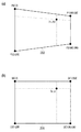
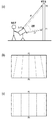
本実施形態では、幾何変換の具体例としてパースペクティブ補正(あおり補正)の例を説明する。図2は、パースペクティブ補正を示す図である。図2(a)がパースペクティブ補正前の四角形を示しており、図2(b)がパースペクティブ補正後の四角形を示している。パースペクティブ補正前の四角形210は台形状であり、四頂点の座標をそれぞれ(0,0),(1600,200),(1600,1000),(0,1200)とする。パースペクティブ補正後の四角形220は長方形であり、四頂点の座標はそれぞれ(0,0),(1600,0),(1600,1200),(0,1200)とする。デジタルカメラなどの撮影装置が、被写体に対して光軸を傾けて撮影すると、得られる撮影画像は、図2(a)に示すように被写体が歪んだ画像になってしまう。そこで撮影画像に対してパースペクティブ補正をすることで、図2(b)に示すように被写体を正面から平行に撮影した画像に変換する。補正対象の撮影画像自体は、各画素に画素値が格納されたデータであり四角形であるが、撮影画像に含まれる一部領域である図2(a)のような四角形を、図2(b)に示す四角形に変換することで、歪みを低減した画像を得られる。処理対象の撮影画像に対して、どのようなパースペクティブ補正を実行するかは、撮影時の撮影装置のモードやユーザによる指定によって決定される。
(Example of geometric transformation)
In this embodiment, an example of perspective correction (tilt correction) will be described as a specific example of geometric transformation. FIG. 2 is a diagram showing perspective correction. FIG. 2A shows a quadrangle before perspective correction, and FIG. 2B shows a quadrangle after perspective correction. The
本実施形態において、補正対象の画像データは外部メモリに格納されているとする。図1の座標入力ポート150へは補正後の四角形220の座標をラスタ順に入力する。すなわち、補正後の四角形220の座標が第1の座標(Ix,Iy)として入力され、これに対応する補正前の四角形210の座標が第2の座標(Hx,Hy)として算出される。本実施形態では、第1の座標(Ix,Iy)⇒第2の座標(Hx,Hy)という非線形な座標変換を線形成分と非線形成分に分解し、座標線形変換部110及び座標非線形変換部120ではそれぞれ第1の座標(Ix,Iy)に対して線形変換及び非線形変換を行う。そして、得られた線形変換結果と非線形変換結果を合成することで、第2の座標(Hx,Hy)を算出する。
In the present embodiment, it is assumed that the image data to be corrected is stored in the external memory. The coordinates of the corrected
(座標変換処理)
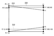
図3は、本実施形態において、座標変換を線形変換と非線形変換とにより実現する方法を説明するための図である。制御部180は、座標変換を線形変換と非線形変換に分解するために、まず図3に示すように、中間データとしてP0’、P1’、P2’、P3’によって定義される四角形310(以降、中間四角形と呼ぶ)を設定する。制御部180は、点P0,P1、P2、P3によって定義されるパースペクティブ補正前の四角形210と、点Q0,Q1,Q2、Q3によって定義されるパースペクティブ補正後の四角形320に基づいて、中間四角形310を決定する。線形変換処理によりパースペクティブ補正後の四角形から中間四角形までの変換を行い、非線形変換処理により、中間四角形からパースペクティブ補正前の四角形までの変換を行うことになる。線形変換処理により主な変換処理を行い、非線形変換処理の演算を少なくさせることが望ましい。そこで制御部180は、第1の座標で構成される四角形220から線形変換の範囲内であり、かつ第2の座標で構成される四角形210(P0/P1/P2/P3)の形状に近い四角形として、中間四角形を算出する。中間四角形310は座標線形変換部110の線形変換結果で構成される。
(Coordinate conversion process)
FIG. 3 is a diagram for explaining a method of realizing a coordinate transformation by a linear transformation and a non-linear transformation in the present embodiment. The
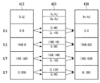
図4は、四角形の四頂点の座標変換例を示す図である。図4において、列410は第1の座標を示す列であり、第1の座標で構成される四角形220の四頂点座標を示している。列430は第2の座標を示す列であり、第2の座標で構成される四角形210の四頂点座標を示している。列420は、列410の各座標に関して上段で線形変換結果、下段で非線形変換結果を示しており、上段と下段の座標の和は列430で示した四角形210の四頂点座標となる。つまり、第1の座標(Ix,Iy)⇒第2の座標(Hx,Hy)という非線形変換を第1の座標(Ix,Iy)⇒線形変換後の座標(Fx,Fy)という線形変換と第1の座標(Ix,Iy)⇒非線形変換後の座標(Gx,Gy)という非線形変換の2つに分解する。
FIG. 4 is a diagram showing an example of coordinate conversion of the four vertices of a quadrangle. In FIG. 4, the
上記変換を実現する座標線形変換部110、座標非線形変換部120の構成について詳細に説明する。ここで、代表的な線形変換であるアフィン変換が適用された場合の座標線形変換部110を説明する。アフィン変換で表現可能な変換を線形変換とし、アフィン変換で表現不可能な変換を非線形変換とする。座標線形変換部110は式(1)に示したアフィン変換関数を演算可能なリソースを備える回路であるとする。
The configuration of the coordinate
![]()
![]()
ここで、アフィン係数a,b,c,d,e,fは制御部180によって設定される変換パラメータである。図3で示した中間四角形310を得るには、a=1.0,b=0.0,c=0.0,d=0.833,e=0.0,f=100.0とすることで所望の線形変換を実現することができる。
Here, the affine coefficients a, b, c, d, e, and f are conversion parameters set by the
座標非線形変換部120では、四角形の四頂点のUV値を基にバイリニア補間を用いたUVマッピングにより非線形変換を実現する。この場合の非線形変換関数を式(2)に示す。
The coordinate

ここで、パラメータ(U0,V0),(U1,V1),(U2,V2),(U3,V3)は第1の座標となる四頂点座標(0,0),(W,0),(W,H),(0,H)を非線形変換した場合の座標である。各パラメータ(U0,V0),(U1,V1),(U2,V2),(U3,V3)は、それぞれ制御部180によって設定される変換パラメータである。本実施形態において、図4で示したように、第1の座標(列410)を非線形変換により差分(列420の下段)へ変換するので、制御部180は次のように四角形の四頂点のUV値を設定することで所望の非線形変換を実現することができる。すなわち、(U0,V0)=(0.0,−100.0),(U1,V1)=(0.0,100.0),(U2,V2)=(0.0,−100.0),(U3,V3)=(0.0,100.0)と設定する。また、本実施形態においてW=1600,H=1200とするが、これに限定されず、W,Hを1024,4096などの2のべき乗に限定することで除算をシフト演算で実現するとしても良い。
Here, the parameters (U0, V0), (U1, V1), (U2, V2), (U3, V3) are the four-vertex coordinates (0,0), (W, 0), which are the first coordinates. These are the coordinates when W, H) and (0, H) are non-linearly converted. Each parameter (U0, V0), (U1, V1), (U2, V2), (U3, V3) is a conversion parameter set by the
座標合成部130では、式(1)による線形変換結果の座標(Fx,Fy)と式(2)による非線形変換結果の座標(Gx,Gy)とを加算する。すなわち式(3)で表される。
In the coordinate synthesizing
![]()
![]()
次に座標変換の演算精度について説明する。上記で説明したように、制御部180は、線形変換で求める線形変換後の座標(Fx,Fy)をできるだけ第2の座標(Hx,Hy)に近い値に設定する。その結果、その差分である非線形変換後の座標(Gx,Gy)の絶対値が取りうる範囲(値域)は、線形変換後の座標(Fx,Fy)に比べて小さくすることができる。例えば上記パースペクティブ補正の例では図4に示したように線形変換後の座標(Fx,Fy)の絶対値は非線形変換後の座標(Gx,Gy)の絶対値の10倍以上となっている。演算誤差は演算結果の絶対値に比例すると考えれば、第2の座標(Hx,Hy)に含まれる誤差は、座標線形変換部110起因の誤差の影響が支配的となる。そのため、座標線形変換部110の演算精度を座標非線形変換部120の演算精度より高く設けることにより、高精度な座標変換を実現することができる。ここで演算精度とは、固定小数点であれば小数点以下のビット数としても良いし、浮動小数点であれば仮数部のビット数としても良い。
Next, the calculation accuracy of the coordinate transformation will be described. As described above, the
(変換パラメータの設定)
制御部180は、取得した四頂点座標に基づいて座標変換処理を線形変換と非線形変換に分解する。図9(a)は、制御部180は実行する処理のフローチャートである。制御部180はCPUであり、ROM(不図示)から図9に示すフローチャートを実現できるプログラムを読み出すことにより、ソフトウェアによって以降の処理は実現する。まずステップS901において制御部180は、パースペクティブ補正前の四角形を定義する4頂点と、パースペクティブ補正後の四角形を定義する4頂点を取得する。ここでは、補正対象の画像のうち、主な被写体である建造物を検出し、建造物の4頂点が歪みのない画像になるように生成するとする。そこで制御部180は、被写体である建造物の4頂点の座標を、パースペクティブ補正前の四角形を定義する4頂点として取得する。また、パースペクティブ補正後の4頂点は、撮影時のモードやユーザ指定、補正対象の画像などにより予め決定される。
(Setting of conversion parameters)
The
ステップS902において制御部180は、ステップS901において取得した2つの4頂点から、中間四角形を決定する。図9(b)は、ステップS902における処理のさらに詳細なフローチャートである。まずステップS905において、パースペクティブ補正後の四角形の頂点Q0〜Q3を候補中間四角形の初期値として設定する。次にステップS906において制御部180は、候補中間四角形の座標それぞれと、パースペクティブ補正前の四角形の頂点P0〜P3それぞれとの差分を算出する。このとき、差分を算出する頂点は、互いに最も近い位置の頂点である。
In step S902, the
次にステップS907において、次の候補中間四角形となる四角形を探索する。具体的には、現在の候補中間四角形のうち少なくとも1つの頂点のX座標もしくはY座標を、対応する補正前の四角形の頂点に1近付ける操作を行う。この時、上記操作は線形変換の範囲内で行う。このような操作が可能な新たな中間四角形が見つかれば、ステップS908に進み、次の候補中間四角形として設定し、ステップS906に戻る。新たな候補中間四角形がなければ、全ての候補中間四角形の差分を算出したとしてステップS909に進む。全ての候補中間四角形についてパースペクティブ補正前の四角形の頂点P0〜P3との差分を算出すると、ステップS909において差分が最小値の候補中間四角形を、中間四角形として決定する。図3の例では、中間四角形310の四頂点の座標は、(0,100),(1600,100),(1600,1100),(0,1100)となる。
Next, in step S907, a quadrangle that becomes the next candidate intermediate quadrangle is searched for. Specifically, the operation of bringing the X coordinate or the Y coordinate of at least one vertex of the current candidate intermediate quadrangle closer to the vertex of the corresponding uncorrected quadrangle is performed. At this time, the above operation is performed within the range of the linear transformation. If a new intermediate quadrangle capable of such an operation is found, the process proceeds to step S908, the next candidate intermediate quadrangle is set, and the process returns to step S906. If there is no new candidate intermediate quadrangle, the process proceeds to step S909 assuming that the differences between all the candidate intermediate quadrilaterals have been calculated. When the difference between the vertices P0 to P3 of the quadrangle before perspective correction is calculated for all the candidate intermediate quadrilaterals, the candidate intermediate quadrangle having the minimum difference is determined as the intermediate quadrangle in step S909. In the example of FIG. 3, the coordinates of the four vertices of the
図9(a)に戻り、ステップS903において制御部180は、線形変換処理に実行させるためのパラメータであるアフィン係数a,b,c,d,e,fを、式(1)と中間四角形の座標に基づいて算出し、座標線形変換部110にパラメータを設定する。
Returning to FIG. 9A, in step S903, the
またステップS904において制御部180は、非線形変換処理に実行させるためのパラメータをパースペクティブ補正前の4頂点の座標と、中間四角形の座標とに基づいて算出し、座標非線形変換部110にパラメータを設定する。座標非線形変換部120は、線形変換結果で構成される中間四角形310と第2の座標で構成される四角形210までの変換処理をする。ここで制御部180は、パラメータを、線形変換結果で構成される中間四角形310と第2の座標で構成される四角形210の差分から算出する。図3の例では、中間四角形310の四頂点座標と四角形210の四頂点座標の差分は、(P0−P0’),(P1−P1’),(P2−P2’),(P3−P3’)となる。式(2)の(U0,V0),(U2,V2)、(U1,V1),(U3,V3)に各差分を代入してパラメータを算出する。
Further, in step S904, the
以上により、制御部180による変換処理の分解を完了する。以上の通り制御部180は、座標変換処理の開始前に算出した分解の結果(変換パラメータ)を、座標線形変換部110及び座標非線形変換部120それぞれに設定する。上記で説明したように,非線形変換結果の座標(Gx,Gy)の絶対値が小さい方が精度の観点から望ましい。そこで本実施形態では、中間四角形の四頂点と最終的な演算結果である四角形210の四頂点の距離の絶対値和(|P0−P0’|+|P1−P1’|+|P2−P2’|+|P3−P3’|)が最小となる中間四角形520を求めた。
As described above, the decomposition of the conversion process by the
(実施形態1の効果)
次にこれら座標変換処理を実現する演算リソースについて説明する.一般に、非線形変換を単体で実現すると、非線形変換は除算など複雑な演算を含むため、高精度にするには回路規模が大きくなる。本実施形態の構成では、非線形変換の精度を落としても影響が少ないため、比較的小さい回路規模で実現できる。なお本実施形態では、座標線形変換部110、座標非線形変換部120、座標合成部130、画像入出力部140それぞれを回路により実現する場合を例に説明した。しかしながらハードウェア化せずにプログラムとして実行する場合でも、同様に演算することで効果を得られる。座標変換のために複雑な演算を高精度に行う演算コストが高い場合、演算の遅延時間増大や消費電力の増大など好ましくない状況を招く。そこで、本実施形態の適用によって演算コストを低減し、上記状況を改善することができる。
(Effect of Embodiment 1)
Next, the arithmetic resources that realize these coordinate transformation processes will be described. In general, when a non-linear conversion is realized by itself, the non-linear conversion involves complicated operations such as division, and therefore the circuit scale becomes large in order to achieve high accuracy. In the configuration of this embodiment, even if the accuracy of the non-linear conversion is lowered, the influence is small, so that it can be realized on a relatively small circuit scale. In this embodiment, a case where each of the coordinate
以上説明したように、上記実施形態では所望の座標変換処理を2つの変換に分解し、それぞれ座標を独立に変換した後に両者の結果を合成する構成とした。2つの変換はそれぞれ、演算精度、演算結果の値域、演算関数(式(1)と式(2))が異なる変換とした。これにより、最終的な演算結果の精度と回路規模との両立ができた。 As described above, in the above embodiment, the desired coordinate conversion process is decomposed into two conversions, the coordinates are converted independently, and then the results of both are combined. The two conversions are different in calculation accuracy, range of calculation result, and calculation function (formula (1) and formula (2)), respectively. This made it possible to achieve both the accuracy of the final calculation result and the circuit scale.
<変形例1>
上記実施形態1では、メモリ上の入力画像に対して幾何変換後の画像をストリーミング出力する例を説明したが、これに限られない。例えば逆にストリーミング入力の画像に対して幾何変換後の画像をメモリ上に書き込むようにしても良い。一般に、入力画像・出力画像のいずれかがストリーミング(ラスタ順)で、もう一方がランダムアクセスになる場合、ストリーミング側の座標を座標入力ポート150から入力し、その座標を変換した結果を基にランダムアクセスする構成とすれば良い。
<Modification 1>
In the first embodiment, an example in which the image after geometric transformation is streamed to the input image on the memory has been described, but the present invention is not limited to this. For example, conversely, the image after geometric transformation may be written in the memory for the image of the streaming input. Generally, when either the input image or the output image is streaming (raster order) and the other is random access, the coordinates on the streaming side are input from the coordinate
本変形例において、画像入力ポート160から入力画像の画素をラスタ順に入力する場合を説明する。座標入力ポート150には上記実施形態1において出力画像の座標が第1の座標として入力されていたが、本変形例では入力画像の座標を第1の座標として入力することとなる。この場合に、算出される第2の座標は出力画像の座標となり、画像入出力部140に渡される。そして、画像入出力部140は、渡された出力画像の座標に対応するメモリアドレスへ入力画像の画素を書き込む。なお、画像入出力部140には数ライン分画像を一時的に記憶するラインバッファを備えても良い。
In this modification, the case where the pixels of the input image are input from the
<実施形態2>
実施形態1では、候補となる中間四角形の全てについて、パースペクティブ補正前の4頂点との差分し、差分が最小となる候補を中間四角形として決定した。実施形態2では、パースペクティブ補正前の4頂点のうち3頂点を用いて、非線形変換結果の座標(Gx,Gy)の絶対値が小さくなるよう座標変換処理を分解する方法について説明する。図5(a)は、本実施形態における座標変換処理の分解方法を説明するための図である。一般に線形変換の範囲内で任意の3点を合わせる座標変換処理が可能である。そこで制御部180は、第2の座標で構成される四角形210の四頂点のうち3点(P0,P1,P3)に合わせるように線形変換した結果得られる四角形を中間四角形として算出する。従って実施形態2では、第1の座標で構成される四角形220の四頂点のうち3点(Q0,Q1,Q3)は、第2の座標で構成される四角形210の四頂点のうち3点(P0,P1,P3)に合わせた中間四角形510に線形変換される。中間四角形510の四頂点はP0,P1,P2’,P3となる。
<
In the first embodiment, all of the candidate intermediate quadrilaterals are different from the four vertices before the perspective correction, and the candidate with the smallest difference is determined as the intermediate quadrangle. In the second embodiment, a method of decomposing the coordinate conversion process so that the absolute value of the coordinates (Gx, Gy) of the nonlinear transformation result becomes small by using three vertices out of the four vertices before the perspective correction will be described. FIG. 5A is a diagram for explaining a decomposition method of the coordinate conversion process in the present embodiment. In general, it is possible to perform a coordinate transformation process that aligns any three points within the range of linear transformation. Therefore, the
図9(c)は、実施形態2における制御部180が実行する処理のフローチャートである。まずステップS910において、第2の座標で構成される四角形210の四頂点を取得し、4頂点のうち、任意の3頂点(ここではP0,P1,P3)を選択する。
FIG. 9C is a flowchart of the process executed by the
ステップS911において制御部180は、Q0,Q1,Q3の座標及びP0,P1,P3の座標をそれぞれ式(1)の(Ix,Iy)及び(Fx,Fy)に代入して得られる方程式を解くことによって、アフィン係数を求める。制御部180は、算出したアフィン係数を座標線形変換部110に設定する。次に、ステップS912において制御部180は、求めたアフィン係数を用いて、中間四角形510の残り1点(P2’)の座標も計算する。
In step S911, the
ステップS913において制御部180は、座標非線形変換部120の変換パラメータ(非線形変換関数を表す式(2)における(U0,V0),(U1,V1),(U2,V2),(U3,V3))を、P2’及びP2の座標に基づいて算出し、設定する。具体的に、式(2)の(U2,V2)に(P2−P2’)の座標を設定し、式(2)の(U0,V0),(U1,V1),(U3,V3)に(0.0,0.0)を設定すれば良い。以上により、実施形態2における座標変換処理の分解処理を完了する。この場合、非線形変換により1点(P2’をP2に)のみ合わせるので、分解自体の計算量(すなわち制御部180の負荷)が比較的少ない方法となる。
In step S913, the
なお、さらに別の分解方法でもよい。図5(b)では、重複領域(斜線部)に着目し、中間四角形の総面積のうち、最終的な演算結果である四角形210と重複する領域の割合が最大(あるいは近似的に最大)となる中間四角形530を求めている。
Further, another decomposition method may be used. In FIG. 5B, focusing on the overlapping area (hatched area), the ratio of the area overlapping with the
以上の中間四角形510,520,530はいずれも図2(b)に示した四角形220から線形変換の範囲内である。そのため、座標線形変換部110に変換パラメータを適切に設定することで線形変換結果として座標を算出することができる。座標非線形変換部120は最終的な演算結果である四角形210と中間四角形の差分のみを非線形変換結果として計算するように変換パラメータが設定される。いずれの中間四角形の場合も差分の絶対値は比較的小さいことが期待できる。なお、分解方法は上記で説明した例に限定されず、他の方法で求めた変換パラメータを用いて座標変換処理を行っても良い。
The above
<変形例2>
上記実施形態1では、座標線形変換部110はアフィン変換、座標非線形変換部120はUV値をバイリニア補間でマッピングすることとしたが、他の演算でも良い。例えば、座標線形変換部110は単純な拡大縮小のみを行うとしても良い。この時、線形変換として、式(4)を実行することとなる。
<
In the first embodiment, the coordinate
![]()
![]()
ここでaは拡大縮小率を表すパラメータとなる。この場合であっても回転や平行移動がないユースケースなどでは十分であり、更なる回路規模低減が可能である。 Here, a is a parameter representing the enlargement / reduction ratio. Even in this case, it is sufficient for use cases where there is no rotation or translation, and the circuit scale can be further reduced.
また、例えば、座標非線形変換部120は奥行きを考慮したUVマッピングを行うとしても良い。この時、非線形変換として、式(5)を実行することとなる。
Further, for example, the coordinate
ここで、Z0,Z1,Z2,Z3はそれぞれ四頂点のデプス(奥行き方向の座標)であり、その他のパラメータは式(2)と同等である。このようにすることでより正確なUV値のマッピングが可能になるが、除算が増えるなど演算は複雑化する。しかし上記実施形態1で説明した構成により座標非線形変換部120は、その精度が座標線形変換部110に比べて低くても最終結果に与える影響が軽微のため、複雑な演算であっても比較的少ない回路規模で実装できる。
Here, Z0, Z1, Z2, and Z3 are the depths (coordinates in the depth direction) of each of the four vertices, and the other parameters are the same as those in the equation (2). By doing so, more accurate UV value mapping becomes possible, but the calculation becomes complicated, such as an increase in division. However, due to the configuration described in the first embodiment, even if the accuracy of the coordinate
<実施形態3>
上記実施形態1では座標合成部130にて、線形変換結果(Fx,Fy)と非線形変換結果(Gx,Gy)の加算を実行したが、他の演算を実行しても良く、例えば乗算や比較(大きい方を選択など)を実行可能な構成としても良い。この場合の座標合成部130の構成例を図6に示す。図6に示したように、入力である線形変換結果(Fx,Fy)と非線形変換結果(Gx,Gy)に対して加算、乗算、比較のいずれかの結果を出力する構成となっている。演算の選択は制御部180から制御する。このような構成とすることでより多様な座標変換を実現できる。
<Embodiment 3>
In the first embodiment, the coordinate
例えば、図2で示した四角形220の座標から四角形210の座標への変換処理を線形変換と非線形変換の乗算に分解する例を説明する。これは、例えば図7に示した中間四角形710を用いて実現できる。すなわち、中間四角形710の座標を座標線形変換部110で求め、座標非線形変換部120で四頂点の座標が(1.0,1.0),(1.0,0.67),(1.0,0.67),(1.0,1.0)となるよう非線形変換を行う。座標合成部130で線形変換結果と非線形変換結果を乗算する。このようにすることで、中間四角形710の左端(P0,P3)は等倍で、右にいくにつれてY方向に縮み、右端(P1’,P2’)はY方向に2/3となる変形が実現できる。以上のように、線形変換と非線形変換の乗算により所望の座標変換が実現できる。
For example, an example of decomposing the conversion process from the coordinates of the
<実施形態4>
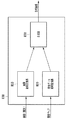
本実施形態では、上記実施形態で説明した幾何変換を画像合成処理に適用する例を示す。図8は本実施形態における画像合成部800の構成例を示す図である。画像幾何変換部810は、動画を構成する複数の画像(フレーム)をメモリ(図示せず)から読み出して、所定の幾何変換処理を実行した後、合成部830に順次供給する。属性データ幾何変換部820は属性マップをメモリ(図示せず)から読み出して、所定の幾何変換処理を実行した後、合成部830に順次供給する。ここで属性マップとは、画像の分割領域ごとに解析処理で算出した属性データ(メタデータ)を分割領域の2次元座標位置に応じて記録するものであり,例えばフレーム間の動き量などを記録するデータである。合成部830では、画素ごとに順次合成処理し、合成結果を出力する。合成処理の際に、属性データに応じて適応的に処理パラメータを切り替える。画像合成処理は、例えばHDR合成処理であり、同じシーンを撮影した露光時間の違う複数の画像に対して、動き量(属性データ)を基に合成割合を決定し、ブレンド処理する。
<Embodiment 4>
In this embodiment, an example of applying the geometric transformation described in the above embodiment to the image composition processing is shown. FIG. 8 is a diagram showing a configuration example of the
画像幾何変換部810では例えば動画を撮影する際の撮影装置のブレを補正する処理を実行する。具体的には、最初のフレームで設定した四角形の4頂点に対応する4頂点を、後続の各フレームから検出し、検出した四角形が所定の長方形となるよう変形する。
一方、属性マップは例えば画像(幾何変換前の画像)の64×64領域ごとに1つの動き量が算出された結果であるとすれば、属性マップは画像に比べ解像度が1/64ということになる。すなわち合成部830へ画素に対応した属性データを入力するには、属性データ幾何変換部820では、上記ブレ補正に相当する幾何変換に加えて64倍の拡大(画像と属性マップの解像度の違いを吸収する処理)となる変換を実行すれば良い。
The image
On the other hand, if the attribute map is the result of calculating one movement amount for each 64 × 64 area of the image (image before geometric transformation), the attribute map has a resolution of 1/64 compared to the image. Become. That is, in order to input the attribute data corresponding to the pixels to the
以上のような構成において、画像幾何変換部810は一般的な射影変換により実装し、属性データ幾何変換部820は実施形態1における画像処理部100を用いて実装する。属性データ幾何変換部820の具体的な設定方法を説明する。変換後の四角形(第1の座標)は上記画像幾何変換部810と同じ(上記所定の長方形)とする。変形前の四角形(第2の座標)は検出した上記4頂点の座標を1/64倍して用いる。
In the above configuration, the image
本実施形態において、実施形態1の画像処理部100とは違って変形するのは画像データではなく属性データに幾何変換を適用することであるが,2次元座標位置に応じて記録されたデータ群であれば同様に適用することができる。一般に、高倍率の拡大縮小処理を実現するには、座標算出に高い演算精度が必要になり、特に非線形変換の場合は演算が複雑なので演算コストが高くなることが懸念される。しかし本実施形態の属性データ幾何変換部820を用いることによって64倍の拡大は線形変換のため、座標線形変換部110で高精度に変換し、残差のみを座標非線形変換部120で求める。これにより演算コストを比較的低く抑えることができる。
In the present embodiment, unlike the
<実施形態5>
上記実施形態1では、変換パラメータを変換前後の四頂点座標に基づいて決定したが、これに限らない。例えば画像撮影機器に距離センサ等が具備されており、被写体までの距離情報が利用可能な場合、距離情報を基に変換パラメータを求めても良い。例として、建物などの平面状の被写体に対して、正面から上方にあおり撮影をする場合に関して図10を用いて説明する。図10(a)に図示したように、カメラの視野の下端P1までの距離をd1、カメラの視野の上端P2までの距離をd2とする。この時、撮影画像は図10(b)のように上端にいくにしたがって水平方向に縮小されたような画像となる。図中の点線は補助線であり、鉛直方向を示している。これを図10(c)のように補正する。すなわち画像下端P1では水平方向に等倍であり、画像上端P2では水平方向にd2/d1倍するような処理となる。以降ではR=d2/d1として説明する。
<Embodiment 5>
In the first embodiment, the conversion parameter is determined based on the coordinates of the four vertices before and after the conversion, but the present invention is not limited to this. For example, if the image capturing device is equipped with a distance sensor or the like and distance information to the subject is available, the conversion parameter may be obtained based on the distance information. As an example, FIG. 10 will be described with respect to a case where a flat subject such as a building is photographed by tilting from the front to the upper side. As shown in FIG. 10A, the distance to the lower end P1 of the field of view of the camera is d1, and the distance to the upper end P2 of the field of view of the camera is d2. At this time, the captured image becomes an image that is reduced in the horizontal direction toward the upper end as shown in FIG. 10 (b). The dotted line in the figure is an auxiliary line and indicates the vertical direction. This is corrected as shown in FIG. 10 (c). That is, at the lower end P1 of the image, the magnification is the same in the horizontal direction, and at the upper end P2 of the image, the processing is such that the magnification is d2 / d1 in the horizontal direction. Hereinafter, it will be described as R = d2 / d1.
以上のような変形を行う場合、線形変換成分を大きくするには、例えば線形変換部110で画像全体を水平方向に(R+1)/2倍(すなわち下端の倍率と上端の倍率の平均)するなどが考えられる。具体的には、アフィン係数をa=(R+1)/2,b=0.0,c=0.0,d=1.0,e=W×(R−1)/4,f=0.0などとすれば良い。ここで、Wは画像幅である。非線形変換のパラメータは、線形変換のパラメータが決定すれば、実施形態1と同様に最終的な演算結果(図10(c))との残差から求めることができる。
In the case of performing the above deformation, in order to increase the linear transformation component, for example, the entire image is horizontally (R + 1) / 2 times (that is, the average of the magnification of the lower end and the magnification of the upper end) in the
以上説明したように、本実施形態では被写体までの距離情報を基に変換パラメータを求める例を示した。なお、変換パラメータは距離情報以外にもジャイロセンサの値やレンズのズーム値などを用いて算出しても良い。機器が固定され、ユースケースが限定されている場合などは、複数のパラメータセットを予め記憶しておき、ユースケースに応じて選択的に切り替える構成としても良い。 As described above, in this embodiment, an example of obtaining a conversion parameter based on the distance information to the subject is shown. The conversion parameter may be calculated by using the value of the gyro sensor, the zoom value of the lens, or the like in addition to the distance information. When the device is fixed and the use cases are limited, a plurality of parameter sets may be stored in advance and selectively switched according to the use cases.
<その他の実施例>
本発明は、上述の実施形態の1以上の機能を実現するプログラムを、ネットワーク又は記憶媒体を介してシステム又は装置に供給し、そのシステム又は装置のコンピュータにおける1つ以上のプロセッサーがプログラムを読出し実行する処理でも実現可能である。また、1以上の機能を実現する回路(例えば、ASIC)によっても実現可能である。
<Other Examples>
The present invention supplies a program that realizes one or more functions of the above-described embodiment to a system or device via a network or storage medium, and one or more processors in the computer of the system or device reads and executes the program. It can also be realized by the processing to be performed. It can also be realized by a circuit (for example, ASIC) that realizes one or more functions.
また、本発明は上述した実施形態に限定されるものではなく、本発明の趣旨を逸脱しない範囲内において、種々の変形、変更して実施することができる。 Further, the present invention is not limited to the above-described embodiment, and can be variously modified or modified within a range that does not deviate from the gist of the present invention.
110 座標線形変換部
120 座標非線形変換部
130 座標合成部
180 制御部
810 画像幾何変換部
820 属性データ幾何変換部
830 合成部
110 Coordinate
Claims (14)
第1の座標から第2の座標への変換処理を、前記第1の座標から第3の座標に変換する線形変換の結果と、前記第1の座標から第4の座標に変換する非線形変換の結果との合成になるようにするために、前記線形変換及び前記非線形変換の変換パラメータを決定する制御手段と、
前記線形変換の変換パラメータに基づく前記線形変換で前記第3の座標を算出する線形変換手段と、
前記非線形変換の変換パラメータに基づく前記非線形変換で、前記第4の座標を算出する非線形変換手段と、
前記第3の座標と前記第4の座標を合成して、前記第2の座標を算出する合成手段と
を有することを特徴とする画像処理装置。 An image processing device that performs geometric transformation on the data recorded according to the two-dimensional coordinate position.
The result of the linear conversion that converts the conversion process from the first coordinate to the second coordinate from the first coordinate to the third coordinate, and the non-linear conversion that converts the first coordinate to the fourth coordinate. A control means for determining the transformation parameters of the linear and nonlinear transformations so that they can be combined with the result.
And linear transformation means for calculating said third coordinate in the linear conversion based on the conversion parameter of the linear transformations,
In the nonlinear conversion based on the conversion parameter of the non-linear transformation, a nonlinear transformation means for calculating the fourth coordinate,
An image processing apparatus comprising: a synthesizing means for synthesizing the third coordinate and the fourth coordinate to calculate the second coordinate.
複数の画像データを幾何変換する画像幾何変換手段と、
属性データを幾何変換する属性データ幾何変換手段と、
前記属性データ幾何変換手段で幾何変換された前記属性データに基づき、前記画像幾何変換手段で幾何変換された前記複数の画像データを合成する画像合成手段と
を有し、
前記属性データ幾何変換手段は、
第1の座標から第2の座標への変換処理を、前記第1の座標から第3の座標に変換する線形変換の結果と、前記第1の座標から第4の座標に変換する非線形変換の結果との合成になるようにするために、前記線形変換及び前記非線形変換の変換パラメータを決定する制御手段と、
前記線形変換の変換パラメータに基づく前記線形変換で前記第3の座標を算出する線形変換手段と、
前記非線形変換の変換パラメータに基づく前記非線形変換で、前記第4の座標を算出する非線形変換手段と、
前記第3の座標と前記第4の座標を合成して、前記第2の座標を算出する合成手段と
を有することを特徴とする画像処理装置。 An image processing device that synthesizes multiple image data.
Image geometric transformation means for geometrically transforming multiple image data,
Attribute data geometric transformation means for geometrically transforming attribute data,
It has an image synthesizing means for synthesizing the plurality of image data geometrically transformed by the image geometric transformation means based on the attribute data geometrically transformed by the attribute data geometric transformation means.
The attribute data geometric transformation means is
The result of the linear conversion that converts the conversion process from the first coordinate to the second coordinate from the first coordinate to the third coordinate, and the non-linear conversion that converts the first coordinate to the fourth coordinate. A control means for determining the transformation parameters of the linear and nonlinear transformations so that they can be combined with the result.
And linear transformation means for calculating said third coordinate in the linear conversion based on the conversion parameter of the linear transformations,
In the nonlinear conversion based on the conversion parameter of the non-linear transformation, a nonlinear transformation means for calculating the fourth coordinate,
An image processing apparatus comprising: a synthesizing means for synthesizing the third coordinate and the fourth coordinate to calculate the second coordinate.
第1の座標から第2の座標への変換処理を、前記第1の座標から第3の座標に変換する線形変換の結果と、前記第1の座標から第4の座標に変換する非線形変換の結果との合成になるようにするために、前記線形変換及び前記非線形変換の変換パラメータを決定する制御工程と、
前記制御工程で決定された前記線形変換の前記変換パラメータに基づく前記線形変換で前記第3の座標を算出する線形変換工程と、
前記制御工程で決定された前記非線形変換の前記変換パラメータに基づく前記非線形変換で、前記第4の座標を算出する非線形変換工程と、
前記第3の座標と前記第4の座標を合成して、前記第2の座標を算出する合成工程と
を有することを特徴とする画像処理方法。 It is an image processing method that performs geometric transformation on the data recorded according to the two-dimensional coordinate position.
The result of the linear conversion that converts the conversion process from the first coordinate to the second coordinate from the first coordinate to the third coordinate, and the non-linear conversion that converts the first coordinate to the fourth coordinate. A control step that determines the transformation parameters of the linear and non-linear transformations so that they can be combined with the results.
A linear transformation step of calculating the third coordinate in the linear transformation based on the transformation parameters of the linear transformation determined in the control process,
In the nonlinear conversion based on the conversion parameter of the non-linear transformation determined in the control step, a nonlinear transformation step of calculating the fourth coordinate,
An image processing method comprising a synthesis step of synthesizing the third coordinate and the fourth coordinate to calculate the second coordinate.
Priority Applications (1)
| Application Number | Priority Date | Filing Date | Title |
|---|---|---|---|
| JP2019224688A JP6972089B2 (en) | 2016-03-10 | 2019-12-12 | Image processing equipment, image processing methods, and programs |
Applications Claiming Priority (2)
| Application Number | Priority Date | Filing Date | Title |
|---|---|---|---|
| JP2016047605A JP6632434B2 (en) | 2016-03-10 | 2016-03-10 | Image processing apparatus, image processing method, and program |
| JP2019224688A JP6972089B2 (en) | 2016-03-10 | 2019-12-12 | Image processing equipment, image processing methods, and programs |
Related Parent Applications (1)
| Application Number | Title | Priority Date | Filing Date |
|---|---|---|---|
| JP2016047605A Division JP6632434B2 (en) | 2016-03-10 | 2016-03-10 | Image processing apparatus, image processing method, and program |
Publications (3)
| Publication Number | Publication Date |
|---|---|
| JP2020038730A JP2020038730A (en) | 2020-03-12 |
| JP2020038730A5 JP2020038730A5 (en) | 2020-04-23 |
| JP6972089B2 true JP6972089B2 (en) | 2021-11-24 |
Family
ID=69738568
Family Applications (1)
| Application Number | Title | Priority Date | Filing Date |
|---|---|---|---|
| JP2019224688A Active JP6972089B2 (en) | 2016-03-10 | 2019-12-12 | Image processing equipment, image processing methods, and programs |
Country Status (1)
| Country | Link |
|---|---|
| JP (1) | JP6972089B2 (en) |
Family Cites Families (2)
| Publication number | Priority date | Publication date | Assignee | Title |
|---|---|---|---|---|
| JP2706711B2 (en) * | 1991-10-23 | 1998-01-28 | 新日本製鐵株式会社 | Method and apparatus for correcting positional distortion of image data |
| JP2005269449A (en) * | 2004-03-19 | 2005-09-29 | Casio Comput Co Ltd | Image processor, image processing method and program |
-
2019
- 2019-12-12 JP JP2019224688A patent/JP6972089B2/en active Active
Also Published As
| Publication number | Publication date |
|---|---|
| JP2020038730A (en) | 2020-03-12 |
Similar Documents
| Publication | Publication Date | Title |
|---|---|---|
| JP5997645B2 (en) | Image processing apparatus and method, and imaging apparatus | |
| TWI524306B (en) | Image transformation and multi-view output systems and methods | |
| JP6041651B2 (en) | Image processing apparatus, image processing method, and program | |
| JP6253280B2 (en) | Imaging apparatus and control method thereof | |
| US10255665B2 (en) | Image processing device and method, image capturing device, program, and record medium | |
| JP2009134509A (en) | Device for and method of generating mosaic image | |
| JP2008079026A (en) | Image processor, image processing method, and program | |
| JP4871820B2 (en) | Video display system and parameter generation method for the system | |
| JP2017011327A (en) | Image processing apparatus, image processing method, and program | |
| TWI517094B (en) | Image calibration method and image calibration circuit | |
| JP2016015037A (en) | Information processing apparatus and control method, and video camera | |
| JP2017191572A (en) | Image processor, method thereof, and program | |
| JP6632434B2 (en) | Image processing apparatus, image processing method, and program | |
| JP2018026007A (en) | Image processing apparatus, image processing method, and program | |
| JP6972089B2 (en) | Image processing equipment, image processing methods, and programs | |
| JP5787637B2 (en) | Image processing apparatus and image processing method | |
| JP5340021B2 (en) | Image processing apparatus, image processing method, and program | |
| JP6278716B2 (en) | Image processing apparatus, image processing method, and program | |
| JP5387289B2 (en) | Image processing apparatus, image processing method and program thereof | |
| JP5387276B2 (en) | Image processing apparatus and image processing method | |
| JP6273881B2 (en) | Image processing apparatus, image processing method, and program | |
| CN118840520B (en) | Camera distortion simulation method, device and electronic equipment | |
| JP5387288B2 (en) | Image processing apparatus, image processing method and program thereof | |
| JP5085589B2 (en) | Image processing apparatus and method | |
| JP6440465B2 (en) | Image processing apparatus, image processing method, and program |
Legal Events
| Date | Code | Title | Description |
|---|---|---|---|
| A621 | Written request for application examination |
Free format text: JAPANESE INTERMEDIATE CODE: A621 Effective date: 20191220 |
|
| A521 | Request for written amendment filed |
Free format text: JAPANESE INTERMEDIATE CODE: A523 Effective date: 20200220 |
|
| A977 | Report on retrieval |
Free format text: JAPANESE INTERMEDIATE CODE: A971007 Effective date: 20210212 |
|
| A131 | Notification of reasons for refusal |
Free format text: JAPANESE INTERMEDIATE CODE: A131 Effective date: 20210302 |
|
| A521 | Request for written amendment filed |
Free format text: JAPANESE INTERMEDIATE CODE: A523 Effective date: 20210428 |
|
| TRDD | Decision of grant or rejection written | ||
| A01 | Written decision to grant a patent or to grant a registration (utility model) |
Free format text: JAPANESE INTERMEDIATE CODE: A01 Effective date: 20211005 |
|
| A61 | First payment of annual fees (during grant procedure) |
Free format text: JAPANESE INTERMEDIATE CODE: A61 Effective date: 20211102 |
|
| R151 | Written notification of patent or utility model registration |
Ref document number: 6972089 Country of ref document: JP Free format text: JAPANESE INTERMEDIATE CODE: R151 |