JP6971620B2 - Indoor unit of air conditioner - Google Patents
Indoor unit of air conditioner Download PDFInfo
- Publication number
- JP6971620B2 JP6971620B2 JP2017090445A JP2017090445A JP6971620B2 JP 6971620 B2 JP6971620 B2 JP 6971620B2 JP 2017090445 A JP2017090445 A JP 2017090445A JP 2017090445 A JP2017090445 A JP 2017090445A JP 6971620 B2 JP6971620 B2 JP 6971620B2
- Authority
- JP
- Japan
- Prior art keywords
- base plate
- recess
- front panel
- claw portion
- indoor unit
- Prior art date
- Legal status (The legal status is an assumption and is not a legal conclusion. Google has not performed a legal analysis and makes no representation as to the accuracy of the status listed.)
- Active
Links
Images


Classifications
-
- F—MECHANICAL ENGINEERING; LIGHTING; HEATING; WEAPONS; BLASTING
- F24—HEATING; RANGES; VENTILATING
- F24F—AIR-CONDITIONING; AIR-HUMIDIFICATION; VENTILATION; USE OF AIR CURRENTS FOR SCREENING
- F24F1/00—Room units for air-conditioning, e.g. separate or self-contained units or units receiving primary air from a central station
- F24F1/0007—Indoor units, e.g. fan coil units
- F24F1/0043—Indoor units, e.g. fan coil units characterised by mounting arrangements
- F24F1/0057—Indoor units, e.g. fan coil units characterised by mounting arrangements mounted in or on a wall
-
- F—MECHANICAL ENGINEERING; LIGHTING; HEATING; WEAPONS; BLASTING
- F24—HEATING; RANGES; VENTILATING
- F24F—AIR-CONDITIONING; AIR-HUMIDIFICATION; VENTILATION; USE OF AIR CURRENTS FOR SCREENING
- F24F13/00—Details common to, or for air-conditioning, air-humidification, ventilation or use of air currents for screening
- F24F13/32—Supports for air-conditioning, air-humidification or ventilation units
-
- F—MECHANICAL ENGINEERING; LIGHTING; HEATING; WEAPONS; BLASTING
- F24—HEATING; RANGES; VENTILATING
- F24F—AIR-CONDITIONING; AIR-HUMIDIFICATION; VENTILATION; USE OF AIR CURRENTS FOR SCREENING
- F24F13/00—Details common to, or for air-conditioning, air-humidification, ventilation or use of air currents for screening
- F24F13/20—Casings or covers
Description
本発明は、ベースプレートに対してフロントパネルが固定された構造を有する空気調和装置の室内機に関するものである。 The present invention relates to an indoor unit of an air conditioner having a structure in which a front panel is fixed to a base plate.
空気調和装置の室内機のケースは、据え付け作業やメンテナンス作業のために着脱可能となっている。例えば特許文献1には、本体ケースの前面パネルを着脱する構成が開示されている。 The case of the indoor unit of the air conditioner is removable for installation work and maintenance work. For example, Patent Document 1 discloses a configuration in which the front panel of the main body case is attached and detached.
しかし、特許文献1の上記構成とは異なり、室内の壁面に固定されたベースプレートとフロントパネルとを固定する場合、ベースプレートとフロントパネルの上部に設けられた固定部が用いられる。固定部としては、ベースプレートに設けられ、下方に凹むと共に挿入穴が形成された凹部と、フロントパネルに設けられ、挿入穴に差し込まれて凹部内に進出して係合する爪部とが用いられる。
固定部がベースプレート及びフロントパネルの上部に存在するので、視認性が悪く、作業者は手探りでの作業となる。このため、固定部の爪部が凹部に挿入された固定状態なのか、爪部が凹部に挿入されていない解除状態なのかが分からず爪部を誤って外してしまい、予期せぬタイミングでフロントパネルを落下させてしまうおそれがある。
However, unlike the above configuration of Patent Document 1, when the base plate and the front panel fixed to the wall surface of the room are fixed, the fixing portion provided on the upper part of the base plate and the front panel is used. As the fixing portion, a recess provided in the base plate, which is recessed downward and has an insertion hole formed therein, and a claw portion provided in the front panel, which is inserted into the insertion hole and advances into the recess to engage with the recess, are used. ..
Since the fixing portion is located on the upper part of the base plate and the front panel, the visibility is poor and the operator has to fumble. For this reason, it is not known whether the claw part of the fixed part is in the fixed state where it is inserted into the concave part or the claw part is not inserted in the concave part, and the claw part is accidentally removed. There is a risk of dropping the panel.
また、室内機の機種に応じて、複数の固定部のうち、凹部に爪部を挿入して固定する箇所と、凹部に爪部を挿入せずに固定部として用いずダミーとする箇所とを設ける場合がある。例えば、フロントパネルが重い機種の場合には、フロントパネルが軽い機種に比べて凹部に爪部を挿入して固定する箇所を多くするといった運用が行われる(すなわち、軽い機種はダミーとして用いる固定部が多い)。この様な場合、固定部の凹部に爪部が挿入されているのか否かを作業者の触手によって確実に認識することが求められる。 Further, depending on the model of the indoor unit, among a plurality of fixing portions, a portion where the claw portion is inserted into the recess and fixed, and a portion where the claw portion is not inserted into the recess and is not used as the fixing portion and is used as a dummy. May be provided. For example, in the case of a model with a heavy front panel, there are more places to insert and fix the claws in the recesses than in the model with a light front panel (that is, the light model has a fixed part used as a dummy). There are many). In such a case, it is required that the tentacles of the operator surely recognize whether or not the claw portion is inserted in the concave portion of the fixing portion.
本発明は、このような事情に鑑みてなされたものであって、ベースプレートとフロントパネルとを着脱する固定部がベースプレートとフロントパネルの上部に設けられている場合であっても、確実に爪部の存在を認識することができる空気調和装置の室内機を提供することを目的とする。 The present invention has been made in view of such circumstances, and even when a fixing portion for attaching / detaching the base plate and the front panel is provided on the upper part of the base plate and the front panel, the claw portion is surely provided. It is an object of the present invention to provide an indoor unit of an air conditioner capable of recognizing the existence of.
上記課題を解決するために、本発明の空気調和装置の室内機は以下の手段を採用する。
すなわち、本発明にかかる空気調和装置の室内機は、室内の壁面に固定されるベースプレートと、該ベースプレートに対して固定されるフロントパネルと、前記ベースプレートの上部と前記フロントパネルの上部との間に設けられ、着脱可能とされた固定部とを備え、前記固定部は、前記ベースプレート及び前記フロントパネルのいずれか一方に設けられ、下方に凹むと共に挿入穴が形成された凹部と、前記ベースプレート及び前記フロントパネルの他方に設けられ、前記挿入穴に差し込まれて前記凹部内に進出して係合する爪部とを備え、前記凹部は、該凹部に挿入された前記爪部との間に触手可能な底面を有していることを特徴とする。
In order to solve the above problems, the indoor unit of the air conditioner of the present invention adopts the following means.
That is, in the indoor unit of the air conditioner according to the present invention, between the base plate fixed to the wall surface of the room, the front panel fixed to the base plate, and the upper part of the base plate and the upper part of the front panel. The fixing portion is provided and is provided with a detachable fixing portion, and the fixing portion is provided on either one of the base plate and the front panel, and is provided with a recess having a downward recess and an insertion hole, and the base plate and the front panel. The other side of the front panel is provided with a claw portion that is inserted into the insertion hole and advances into and engages with the recess, and the recess can be tentacled between the recess and the claw portion inserted into the recess. It is characterized by having a simple bottom surface.
固定部の凹部に設けた挿入穴に爪部を挿入して係合することによって、ベースプレートとフロントパネルとを着脱可能に固定する。凹部には、挿入された爪部との間に作業者の指で触手可能な底面が設けられているので、作業者が底面と爪部との段差を触手によって認識し、爪部の存在を確認することができる。したがって、ベースプレートとフロントパネルとを着脱する固定部がベースプレートとフロントパネルの上部に設けられており、作業者が視認困難な場合であっても、確実に爪部の存在を認識することができる。 The base plate and the front panel are detachably fixed by inserting and engaging the claws in the insertion holes provided in the recesses of the fixing portions. Since the recess is provided with a bottom surface that can be touched by the operator's finger between the inserted claw portion, the operator recognizes the step between the bottom surface and the claw portion by the tentacle, and the presence of the claw portion is recognized. You can check. Therefore, a fixing portion for attaching / detaching the base plate and the front panel is provided on the upper part of the base plate and the front panel, and the presence of the claw portion can be reliably recognized even when the operator is difficult to see.
また、本発明にかかる空気調和装置の室内機は、室内の壁面に固定されるベースプレートと、該ベースプレートに対して固定されるフロントパネルと、前記ベースプレートの上部と前記フロントパネルの上部との間に設けられ、着脱可能とされた固定部とを備え、前記固定部は、前記ベースプレート及び前記フロントパネルのいずれか一方に設けられ、下方に凹むと共に挿入穴が形成された凹部と、前記ベースプレート及び前記フロントパネルの他方に設けられ、前記挿入穴に差し込まれて前記凹部内に進出して係合する爪部とを備え、前記爪部の上面には、複数の凹所又は凸部が設けられていることを特徴とする。 Further, the indoor unit of the air conditioner according to the present invention has a base plate fixed to the wall surface of the room, a front panel fixed to the base plate, and an upper portion of the base plate and an upper portion of the front panel. It is provided with a fixing portion provided and detachable, and the fixing portion is provided on either one of the base plate and the front panel, and is provided with a recess having a downward recess and an insertion hole, and the base plate and the front panel. A claw portion provided on the other side of the front panel, which is inserted into the insertion hole and advances into and engages with the recess, is provided, and a plurality of recesses or protrusions are provided on the upper surface of the claw portion. It is characterized by being.
固定部の凹部に設けた挿入穴に爪部を挿入して係合することによって、ベースプレートとフロントパネルとを着脱可能に固定する。爪部の上面には、凹所又は凸部が設けられているので、作業者が凹所又は凸部の段差を触手によって認識し、爪部の存在を確認することができる。したがって、ベースプレートとフロントパネルとを着脱する固定部がベースプレートとフロントパネルの上部に設けられており、作業者が視認困難な場合であっても、確実に爪部の存在を認識することができる。 The base plate and the front panel are detachably fixed by inserting and engaging the claws in the insertion holes provided in the recesses of the fixing portions. Since the concave portion or the convex portion is provided on the upper surface of the claw portion, the operator can recognize the step of the concave portion or the convex portion by the tentacle and confirm the existence of the claw portion. Therefore, a fixing portion for attaching / detaching the base plate and the front panel is provided on the upper part of the base plate and the front panel, and the presence of the claw portion can be reliably recognized even when the operator is difficult to see.
さらに、本発明の空気調和装置の室内機では、前記固定部は、複数設けられ、複数の前記固定部の少なくとも1つには、前記爪部が前記凹部に配置され、その他の前記固定部には、前記爪部がない爪無し固定部が設けられることによって、前記爪部が前記凹部に配置されていないことを特徴とする。 Further, in the indoor unit of the air conditioner of the present invention, a plurality of the fixing portions are provided, and the claw portion is arranged in the recess in at least one of the plurality of fixing portions, and the other fixing portions have the claw portion. Is characterized in that the claw portion is not arranged in the recess due to the provision of the clawless fixing portion without the claw portion.
複数の固定部の少なくとも1つには、爪部が凹部に配置され、その他の固定部には爪部が凹部に配置されていない。したがって、室内機の機種によって、爪部と凹部の組み合わせを変えることができる。例えば、重い機種の場合には軽い機種に比べて多くの爪部を凹部に係合させることとする。このような場合であっても、作業者は、爪部が存在する固定部と存在しない固定部とを判別することができるので、機種が異なっていても作業を誤ることがない。 The claw portion is arranged in the recess in at least one of the plurality of fixing portions, and the claw portion is not arranged in the recess in the other fixing portions. Therefore, the combination of the claw portion and the concave portion can be changed depending on the model of the indoor unit. For example, in the case of a heavy model, more claws are engaged with the recesses than in the case of a light model. Even in such a case, the operator can distinguish between the fixed portion in which the claw portion is present and the fixed portion in which the claw portion is not present, so that the work is not mistaken even if the model is different.
凹部に挿入された前記爪部との間に触手可能な底面を凹部に設けることとしたので、ベースプレートとフロントパネルとを着脱する固定部がベースプレートとフロントパネルの上部に設けられている場合であっても、確実に爪部の存在を認識することができる。 Since it was decided to provide a tentacleable bottom surface in the recess between the claws inserted in the recess, there is a case where a fixing portion for attaching / detaching the base plate and the front panel is provided on the upper part of the base plate and the front panel. However, the presence of the claw portion can be reliably recognized.
以下に、本発明にかかる一実施形態について、図面を参照して説明する。
図1には、空気調和装置の室内機1の外観が示されている。室内機1は、壁掛形とされており、上方から室内空気を吸い込み、下方から室内へと空調後の空気を吹き出す。室内機1は、図示しない室外機と接続されており、室外機にて圧縮された冷媒の供給を受け、室内機1の内部に設けられた室内熱交換器によって室内の空気を所定温度に調整する。
Hereinafter, an embodiment according to the present invention will be described with reference to the drawings.
FIG. 1 shows the appearance of the indoor unit 1 of the air conditioner. The indoor unit 1 is a wall-mounted type, sucks indoor air from above, and blows out air after air conditioning from below to the room. The indoor unit 1 is connected to an outdoor unit (not shown), receives the supply of the refrigerant compressed by the outdoor unit, and adjusts the indoor air to a predetermined temperature by the indoor heat exchanger provided inside the indoor unit 1. do.
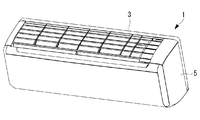
室内機1は、室内の壁面に固定されたベースプレート3と、ベースプレート3の前方に位置し、ベースプレート3に対して着脱可能に固定されるフロントパネル5とを備えている。
The indoor unit 1 includes a
図2には、室内機1を上方から見た平面図が示されている。同図において室内の壁面側が奥となっている。室内機1の壁面側には、室内機1の幅方向(同図において左右方向)に沿って複数の固定部7が設けられている。本実施形態では、同図において左方から、第1固定部7a、第2固定部7b、第3固定部7c、第4固定部7d及び第5固定部7eの5つの固定部7が設けられている。もちろん固定部7の数はこれに限定されるものではなく、6つ以上であっても良い。
FIG. 2 shows a plan view of the indoor unit 1 as viewed from above. In the figure, the wall side of the room is at the back. On the wall surface side of the indoor unit 1, a plurality of
固定部7は、室内機1を正面から見ると、室内機1の奥側でかつ上方に位置している。したがって、下方からアクセスする作業者にとっては視認性が悪い位置に固定部7が位置している。このため、作業者は手探りで固定部7にアクセスすることになる。
The
図3に示すように、固定部7は、ベースプレート3の上方に設けられた凹部8と、フロントパネル5に設けられた爪部9とを備えている。なお、図4には、爪部9が存在していない凹部8が示されており、図5には爪部9のみが示されている。
As shown in FIG. 3, the
凹部8は、ベースプレート3の上面から下方に凹んだ底面8aが形成されている。底面8aの幅方向における中央は平坦面とされている。凹部8の手前側には、爪部9が挿入可能とされた挿入穴8bが設けられている。
The
爪部9は、フロントパネル5の上部のベースプレート3側の端面から、ベースプレート3に向かって突出するように設けられている。爪部9は、図3のように平面視すると、幅広な略矩形状とされている。爪部9は、取り付けた場合に、凹部8の底面8aの平坦面に亘って配置されている。爪部9の下面には図示しない係止部が設けられており、ベースプレート3側の被係止部に係合するようになっている。この係合は、爪部9の上面を押圧することによって外れるようになっている。
The
爪部9の側方と凹部8の側部との間には、作業者の指が入り触手可能な寸法Aとされた隙間10が設けられている。寸法Aとしては、2mmから5mmとされる。この隙間10によって、作業者は凹部8の底面8aと爪部9との段差を触手によって認識できるようになっている。なお、隙間10は、図3のように爪部9の両側に設けても良いし、爪部9の片側のみに設けても良い。
A
爪部9の上面には、幅方向に並んだ2つの凸部9aが設けられている。凸部9aの頂面は平坦面とされている。これら凸部9aは、作業者の触手によって段差が認識可能な形状とされている。なお、凸部9aの数は3つ以上であっても良いし、1つのみであっても良い。また、凸部9aに代えて凹んだ凹所としても良い。
Two
図2に示すように、固定部7の凹部8の全てに爪部9が挿入されて固定されているわけではない。図2では、第3固定部7cには爪部9が挿入されていない。すなわち、フロントパネル5には、第3固定部7cに対応する位置に爪部9を備えていない。その他の固定部7すなわち第1固定部7a、第2固定部7b、第4固定部7d及び第5固定部7eには、爪部9が挿入されている。したがって、これら固定部7a,7b,7d,7eに対応する位置には、フロントパネル5に爪部9が設けられている。このような構成としたのは、ベースプレート3を共通化して、フロントパネル5を機種に応じて使い分けるためである。例えば、重い機種の場合には軽い機種に比べて多くの爪部9をフロントパネル5に設ける。したがって、軽い機種の場合には、例えば、第1固定部7a、第3固定部7c及び第5固定部7eの3箇所に対応する位置のみに爪部9を設ける。
As shown in FIG. 2, the
上述の室内機1によれば、以下の作用効果を奏する。
固定部7の凹部8に挿入された爪部9との間に、作業者の指で触手可能な底面8aが設けられているので、作業者が底面8aと爪部9との段差を触手によって認識し、爪部9の存在を確認することができる。したがって、ベースプレート3とフロントパネル5とを着脱する固定部7がベースプレート3とフロントパネル5の上部に設けられており、作業者が視認困難な場合であっても、確実に爪部9の存在を認識することができる。
According to the indoor unit 1 described above, the following effects are obtained.
Since the
爪部9の上面に、凸部9aを設けることとしたので、作業者が凸部9aの段差を触手によって認識し、爪部9の存在を確認することができる。したがって、ベースプレート3とフロントパネル5とを着脱する固定部7がベースプレート3とフロントパネル5の上部に設けられており、作業者が視認困難な場合であっても、確実に爪部9の存在を認識することができる。
Since the
複数の固定部7の少なくとも1つには、爪部9が凹部8に配置され、その他の固定部7には爪部9が凹部8に配置されないようにして、室内機1の機種によって、爪部9と凹部8の組み合わせを変えることとした。具体的には、重い機種の場合には軽い機種に比べて多くの爪部9を凹部8に係合させることとする。このような場合であっても、作業者は、爪部9が存在する固定部7と存在しない固定部7とを判別することができるので、機種が異なっていても作業を誤ることがない。
The
なお、上述した実施形態では、凹部8をベースプレート3に設け、爪部9をフロントパネル5に設ける構成としたが、爪部9をベースプレート3に設け、凹部8をフロントパネル5に設ける構成としても良い。
In the above-described embodiment, the
1 室内機
3 ベースプレート
5 フロントパネル
7 固定部
8 凹部
8a 底面
8b 挿入穴
9 爪部
9a 凸部
1
Claims (3)
該ベースプレートに対して固定されるフロントパネルと、
前記ベースプレートの上部と前記フロントパネルの上部との間に設けられ、着脱可能とされた固定部と、
を備え、
前記固定部は、前記ベースプレート及び前記フロントパネルのいずれか一方に設けられ、下方に凹むと共に挿入穴が形成された凹部と、前記ベースプレート及び前記フロントパネルの他方に設けられ、前記挿入穴に差し込まれて前記凹部内に進出して係合する爪部とを備え、
前記凹部は、該凹部に挿入された前記爪部との間に触手可能な底面を有している空気調和装置の室内機。 The base plate fixed to the wall of the room and
The front panel fixed to the base plate and
A removable fixing portion provided between the upper part of the base plate and the upper part of the front panel,
Equipped with
The fixing portion is provided in either one of the base plate and the front panel, and is provided in a recess in which an insertion hole is formed while being recessed downward, and is provided in the other of the base plate and the front panel and is inserted into the insertion hole. It is provided with a claw portion that advances into the recess and engages with the recess.
The recess is an indoor unit of an air conditioner having a tentacleable bottom surface between the recess and the claw portion inserted in the recess.
該ベースプレートに対して固定されるフロントパネルと、
前記ベースプレートの上部と前記フロントパネルの上部との間に設けられ、着脱可能とされた固定部と、
を備え、
前記固定部は、前記ベースプレート及び前記フロントパネルのいずれか一方に設けられ、下方に凹むと共に挿入穴が形成された凹部と、前記ベースプレート及び前記フロントパネルの他方に設けられ、前記挿入穴に差し込まれて前記凹部内に進出して係合する爪部とを備え、
前記爪部の上面には、複数の凹所又は凸部が設けられている空気調和装置の室内機。 The base plate fixed to the wall of the room and
The front panel fixed to the base plate and
A removable fixing portion provided between the upper part of the base plate and the upper part of the front panel,
Equipped with
The fixing portion is provided in either one of the base plate and the front panel, and is provided in a recess in which an insertion hole is formed while being recessed downward, and is provided in the other of the base plate and the front panel and is inserted into the insertion hole. It is provided with a claw portion that advances into the recess and engages with the recess.
An indoor unit of an air conditioner in which a plurality of concave portions or convex portions are provided on the upper surface of the claw portion.
複数の前記固定部の少なくとも1つには、前記爪部が前記凹部に配置され、
その他の前記固定部には、前記爪部がない爪無し固定部が設けられることによって、前記爪部が前記凹部に配置されていない請求項1又は2に記載の空気調和装置の室内機。 A plurality of the fixing portions are provided.
In at least one of the plurality of fixing portions, the claw portion is arranged in the recess.
The indoor unit of the air conditioner according to claim 1 or 2, wherein the other fixing portion is provided with a clawless fixing portion having no claw portion, so that the claw portion is not arranged in the recess.
Priority Applications (4)
| Application Number | Priority Date | Filing Date | Title |
|---|---|---|---|
| JP2017090445A JP6971620B2 (en) | 2017-04-28 | 2017-04-28 | Indoor unit of air conditioner |
| AU2018259337A AU2018259337B2 (en) | 2017-04-28 | 2018-03-16 | Indoor unit for air conditioning device |
| EP18792290.1A EP3543619A4 (en) | 2017-04-28 | 2018-03-16 | Indoor unit for air conditioning device |
| PCT/JP2018/010372 WO2018198585A1 (en) | 2017-04-28 | 2018-03-16 | Indoor unit for air conditioning device |
Applications Claiming Priority (1)
| Application Number | Priority Date | Filing Date | Title |
|---|---|---|---|
| JP2017090445A JP6971620B2 (en) | 2017-04-28 | 2017-04-28 | Indoor unit of air conditioner |
Publications (3)
| Publication Number | Publication Date |
|---|---|
| JP2018189281A JP2018189281A (en) | 2018-11-29 |
| JP2018189281A5 JP2018189281A5 (en) | 2020-06-11 |
| JP6971620B2 true JP6971620B2 (en) | 2021-11-24 |
Family
ID=63918376
Family Applications (1)
| Application Number | Title | Priority Date | Filing Date |
|---|---|---|---|
| JP2017090445A Active JP6971620B2 (en) | 2017-04-28 | 2017-04-28 | Indoor unit of air conditioner |
Country Status (4)
| Country | Link |
|---|---|
| EP (1) | EP3543619A4 (en) |
| JP (1) | JP6971620B2 (en) |
| AU (1) | AU2018259337B2 (en) |
| WO (1) | WO2018198585A1 (en) |
Families Citing this family (1)
| Publication number | Priority date | Publication date | Assignee | Title |
|---|---|---|---|---|
| CN111237978A (en) * | 2020-02-20 | 2020-06-05 | 珠海格力电器股份有限公司 | Air conditioner and control method thereof |
Family Cites Families (12)
| Publication number | Priority date | Publication date | Assignee | Title |
|---|---|---|---|---|
| JPS5816582Y2 (en) * | 1977-11-30 | 1983-04-04 | 株式会社東芝 | Air conditioner indoor unit |
| JPS54154506U (en) * | 1978-04-18 | 1979-10-27 | ||
| JPH0794923B2 (en) * | 1989-08-29 | 1995-10-11 | 三菱電機株式会社 | Air conditioner mounting device |
| JPH0468925U (en) * | 1990-10-19 | 1992-06-18 | ||
| JPH0611150A (en) * | 1992-06-29 | 1994-01-21 | Hitachi Ltd | Installing device for air conditioner |
| JPH09324927A (en) * | 1996-06-06 | 1997-12-16 | Fujitsu General Ltd | Installation apparatus for air conditioner |
| JPH10227476A (en) * | 1997-02-14 | 1998-08-25 | Mitsubishi Heavy Ind Ltd | Installation device for air conditioner |
| JP4451956B2 (en) * | 2000-01-19 | 2010-04-14 | 三菱重工業株式会社 | Indoor unit |
| JP3879432B2 (en) * | 2000-04-24 | 2007-02-14 | 松下電器産業株式会社 | Air conditioner installation equipment |
| JP2007147118A (en) | 2005-11-25 | 2007-06-14 | Fujitsu General Ltd | Air conditioner |
| JP2011064353A (en) * | 2009-09-15 | 2011-03-31 | Sharp Corp | Air conditioner |
| JP6272121B2 (en) * | 2014-04-21 | 2018-01-31 | 三菱電機株式会社 | Air conditioner |
-
2017
- 2017-04-28 JP JP2017090445A patent/JP6971620B2/en active Active
-
2018
- 2018-03-16 EP EP18792290.1A patent/EP3543619A4/en not_active Withdrawn
- 2018-03-16 AU AU2018259337A patent/AU2018259337B2/en active Active
- 2018-03-16 WO PCT/JP2018/010372 patent/WO2018198585A1/en unknown
Also Published As
| Publication number | Publication date |
|---|---|
| EP3543619A4 (en) | 2019-12-18 |
| EP3543619A1 (en) | 2019-09-25 |
| JP2018189281A (en) | 2018-11-29 |
| WO2018198585A1 (en) | 2018-11-01 |
| AU2018259337B2 (en) | 2020-08-06 |
| AU2018259337A1 (en) | 2019-07-11 |
Similar Documents
| Publication | Publication Date | Title |
|---|---|---|
| JP5489956B2 (en) | Air conditioner | |
| JP6289663B2 (en) | Air conditioner indoor unit | |
| JP6971620B2 (en) | Indoor unit of air conditioner | |
| JP5370191B2 (en) | Air conditioner indoor unit | |
| JP5402851B2 (en) | Air conditioner outdoor unit | |
| JP2009287854A (en) | Air conditioner | |
| JP2011094838A (en) | Indoor unit | |
| JPWO2018185842A1 (en) | Air conditioner indoor unit | |
| JP6479214B2 (en) | Air conditioner indoor unit | |
| JP2004245571A (en) | Air conditioner | |
| JP2020026906A (en) | Network repeater | |
| JP5277016B2 (en) | Air conditioner outdoor unit | |
| JP2008215687A (en) | Air conditioner | |
| JP5011022B2 (en) | Embedded ceiling air conditioner | |
| CN208527642U (en) | A kind of laboratory hood column unit, column and laboratory hood | |
| JP6827551B2 (en) | Outdoor unit of air conditioner | |
| EP3521726A1 (en) | Indoor unit for air conditioning device | |
| JP3071081B2 (en) | Air conditioner | |
| JP2018189281A5 (en) | ||
| CN209355468U (en) | Base plate of air conditioner, cabinet air-conditioner and air conditioner | |
| JP5542867B2 (en) | Drop-in stove | |
| JP6135739B2 (en) | Air conditioner indoor unit | |
| CN217011213U (en) | Ceiling type AP equipment convenient to location installation | |
| CN210220009U (en) | Air conditioner | |
| JP2009250459A (en) | Outdoor unit of air conditioner |
Legal Events
| Date | Code | Title | Description |
|---|---|---|---|
| A521 | Request for written amendment filed |
Free format text: JAPANESE INTERMEDIATE CODE: A523 Effective date: 20200415 |
|
| A621 | Written request for application examination |
Free format text: JAPANESE INTERMEDIATE CODE: A621 Effective date: 20200415 |
|
| A131 | Notification of reasons for refusal |
Free format text: JAPANESE INTERMEDIATE CODE: A131 Effective date: 20210209 |
|
| A521 | Request for written amendment filed |
Free format text: JAPANESE INTERMEDIATE CODE: A523 Effective date: 20210402 |
|
| TRDD | Decision of grant or rejection written | ||
| A01 | Written decision to grant a patent or to grant a registration (utility model) |
Free format text: JAPANESE INTERMEDIATE CODE: A01 Effective date: 20211005 |
|
| A61 | First payment of annual fees (during grant procedure) |
Free format text: JAPANESE INTERMEDIATE CODE: A61 Effective date: 20211102 |
|
| R150 | Certificate of patent or registration of utility model |
Ref document number: 6971620 Country of ref document: JP Free format text: JAPANESE INTERMEDIATE CODE: R150 |