JP6971084B2 - Methods and devices for generating data that expresses the blur associated with light field data - Google Patents
Methods and devices for generating data that expresses the blur associated with light field data Download PDFInfo
- Publication number
- JP6971084B2 JP6971084B2 JP2017156980A JP2017156980A JP6971084B2 JP 6971084 B2 JP6971084 B2 JP 6971084B2 JP 2017156980 A JP2017156980 A JP 2017156980A JP 2017156980 A JP2017156980 A JP 2017156980A JP 6971084 B2 JP6971084 B2 JP 6971084B2
- Authority
- JP
- Japan
- Prior art keywords
- optical system
- pixel
- pupil
- polygon
- vertices
- Prior art date
- Legal status (The legal status is an assumption and is not a legal conclusion. Google has not performed a legal analysis and makes no representation as to the accuracy of the status listed.)
- Active
Links
- 238000000034 method Methods 0.000 title claims description 49
- 230000003287 optical effect Effects 0.000 claims description 155
- 210000001747 pupil Anatomy 0.000 claims description 107
- 238000005070 sampling Methods 0.000 claims description 23
- 238000004590 computer program Methods 0.000 claims description 3
- 238000012545 processing Methods 0.000 description 10
- 238000003384 imaging method Methods 0.000 description 6
- 239000002609 medium Substances 0.000 description 6
- 230000008569 process Effects 0.000 description 4
- 238000009877 rendering Methods 0.000 description 4
- 230000008901 benefit Effects 0.000 description 3
- 238000004364 calculation method Methods 0.000 description 3
- 238000010586 diagram Methods 0.000 description 3
- 238000012986 modification Methods 0.000 description 3
- 230000004048 modification Effects 0.000 description 3
- 239000007787 solid Substances 0.000 description 3
- 230000004075 alteration Effects 0.000 description 2
- 230000004907 flux Effects 0.000 description 2
- 230000006870 function Effects 0.000 description 2
- 230000010354 integration Effects 0.000 description 2
- 230000035945 sensitivity Effects 0.000 description 2
- 239000006163 transport media Substances 0.000 description 2
- 238000003491 array Methods 0.000 description 1
- 238000004891 communication Methods 0.000 description 1
- 230000001419 dependent effect Effects 0.000 description 1
- 230000006872 improvement Effects 0.000 description 1
- 239000000203 mixture Substances 0.000 description 1
- 239000004065 semiconductor Substances 0.000 description 1
- 238000000926 separation method Methods 0.000 description 1
- 239000013589 supplement Substances 0.000 description 1
- 230000000153 supplemental effect Effects 0.000 description 1
Images


Classifications
-
- G06T5/70—
-
- G—PHYSICS
- G06—COMPUTING; CALCULATING OR COUNTING
- G06T—IMAGE DATA PROCESSING OR GENERATION, IN GENERAL
- G06T7/00—Image analysis
- G06T7/50—Depth or shape recovery
- G06T7/55—Depth or shape recovery from multiple images
- G06T7/557—Depth or shape recovery from multiple images from light fields, e.g. from plenoptic cameras
-
- H—ELECTRICITY
- H04—ELECTRIC COMMUNICATION TECHNIQUE
- H04N—PICTORIAL COMMUNICATION, e.g. TELEVISION
- H04N23/00—Cameras or camera modules comprising electronic image sensors; Control thereof
- H04N23/60—Control of cameras or camera modules
- H04N23/67—Focus control based on electronic image sensor signals
-
- G—PHYSICS
- G06—COMPUTING; CALCULATING OR COUNTING
- G06T—IMAGE DATA PROCESSING OR GENERATION, IN GENERAL
- G06T17/00—Three dimensional [3D] modelling, e.g. data description of 3D objects
- G06T17/20—Finite element generation, e.g. wire-frame surface description, tesselation
-
- H—ELECTRICITY
- H04—ELECTRIC COMMUNICATION TECHNIQUE
- H04N—PICTORIAL COMMUNICATION, e.g. TELEVISION
- H04N13/00—Stereoscopic video systems; Multi-view video systems; Details thereof
- H04N13/20—Image signal generators
- H04N13/204—Image signal generators using stereoscopic image cameras
- H04N13/207—Image signal generators using stereoscopic image cameras using a single 2D image sensor
- H04N13/232—Image signal generators using stereoscopic image cameras using a single 2D image sensor using fly-eye lenses, e.g. arrangements of circular lenses
-
- G—PHYSICS
- G06—COMPUTING; CALCULATING OR COUNTING
- G06T—IMAGE DATA PROCESSING OR GENERATION, IN GENERAL
- G06T2207/00—Indexing scheme for image analysis or image enhancement
- G06T2207/10—Image acquisition modality
- G06T2207/10052—Images from lightfield camera
Description
本発明は、プレノプティック撮像(plenoptic imaging)の分野におけるものであり、ライト・フィールド・コンテンツに関連するボケ(bokeh)情報を生成する技術に関連する。 The present invention is in the field of plenoptic imaging and relates to techniques for generating bokeh information associated with light field content.
画像捕捉デバイスは、3次元的なシーンを2次元的なセンサーに投影する。動作の際、従来のキャプチャー・デバイスは、デバイス内のフォトセンサー(又はフォトディテクタ或いはフォトサイト)に到達する光の量を表現するシーンの2次元(2-D)画像を捕捉する。しかしながら、この2-D画像は、(ライト・フィールドと言及される)フォトセンサーに届く光線の方向分布に関する情報を何ら含んでいない。例えば、この捕捉の最中に、深度又は奥行き(Depth)は失われる。従って、従来のキャプチャー・デバイスは、シーンからの光分布に関する情報の大部分を保存していない。 The image capture device projects a 3D scene onto a 2D sensor. In operation, a conventional capture device captures a two-dimensional (2-D) image of a scene that represents the amount of light that reaches a photosensor (or photodetector or photosite) within the device. However, this 2-D image does not contain any information about the directional distribution of light rays reaching the photosensor (referred to as the light field). For example, during this capture, depth or depth is lost. Therefore, traditional capture devices do not store most of the information about the light distribution from the scene.
「ライト・フィールド・データ取得デバイス(light-field data acquisition devices)」と言及されても良いライト・フィールド・キャプチャー・デバイスは、そのシーンの様々な視点からの光を捕捉することにより、シーンの4次元ライト・フィールド(a four-dimensional (4D) light-field)を測定するように設計されている。フォトレジスタと交わる光ビームの各々に沿って進行する光の量を測定することにより、これらのデバイスは、追加的な光学情報(特に、光線束の方向分布に関する情報)を捕捉し、事後的な処理による新たなイメージング・アプリケーションをもたらすことが可能である。ライト・フィールド・キャプチャー・デバイスにより獲得/取得される情報は、ライト・フィールド・データとして言及される。ライト・フィールド・キャプチャー・デバイスは、ライト・フィールド・データを捕捉することが可能な任意のデバイスとしてここでは定義される。幾つかの種類のライト・フィールド・キャプチャー・デバイスが存在し、例えば次のようなものがある:
− 画像センサー及びメイン・レンズの間に配置されるマイクロレンズ・アレイを利用するプレノプティック・デバイス(例えば、US2013/0222633);
− 「Wilburn et al.,"High performance imaging using large camera arrays." ACM Transactions on Graphics (TOG) 24, no. 3 (2005): 765-776」及び特許文献US 8514491B2に記載されているようなカメラ・アレイ;等である。
Light-field capture devices, which may be referred to as "light-field data acquisition devices," are 4 of the scenes by capturing light from different perspectives of the scene. It is designed to measure a four-dimensional (4D) light-field. By measuring the amount of light traveling along each of the light beams that intersect the photoresistor, these devices capture additional optical information, especially information about the directional distribution of the light flux, and are ex post facto. It is possible to bring about new imaging applications by processing. Information acquired / acquired by the write field capture device is referred to as light field data. A write field capture device is defined herein as any device capable of capturing write field data. There are several types of light field capture devices, such as:
-A prenoptic device that utilizes a microlens array placed between the image sensor and the main lens (eg, US2013 / 0222633);
− Cameras as described in “Wilburn et al.,“ High performance imaging using large camera arrays. ”ACM Transactions on Graphics (TOG) 24, no. 3 (2005): 765-776” and US 8514491B2. -Array; etc.
ライト・フィールド・データ処理は、特に、シーンのリフォーカスされた画像を生成すること、シーンの透視図(perspective views)を生成すること、シーンの深度マップを生成すること、被写界深度拡大(extended depth of field (EDOF))画像を生成すること、立体画像を生成すること、及び/又は、これらの任意の組み合わせを含んで良いが、これらに限定されない。 Light field data processing, in particular, produces refocused images of the scene, perspective views of the scene, depth of field maps of the scene, and depth of field expansion ( Extended depth of field (EDOF)) Generating images, generating stereoscopic images, and / or any combination thereof, but not limited to these.
ライト・フィールド取得デバイスにより取得される画像又はビデオは、例えば、ディスプレイ・デバイスのような他のデバイスへ送られる必要がある。 The image or video acquired by the light field acquisition device needs to be sent to another device, for example, a display device.
ユーザーがディスプレイ・デバイスでライト・フィールド・コンテンツの表示を希望する場合、彼/彼女は、コンテンツのうち様々な部分に焦点を合わせる又は焦点をずらすために、コンテンツのうちの様々な部分を選択して良い。フォーカス面は所望の深度に設定され、深度データは、ユーザーにより選択される画像部分にリフォーカスするために使用される。 If the user wants to display the light field content on a display device, he / she selects different parts of the content in order to focus or defocus the different parts of the content. It's okay. The focus plane is set to the desired depth and the depth data is used to refocus the image portion selected by the user.
しかしながら、そのように合成されるピクチャーは、現実感及び美的品質に欠けてしまうかもしれない。実際には、レンズにより生成される画像のうち焦点が合ってない部分は、不鮮明になる(blurred)。そのような不鮮明性の美的品質は「ボケ(bokeh)」と呼ばれ、ボケは「レンズが光の焦点外れ点(out-of-focus points of light)にする経路」として定義されても良い。レンズの収差及び開口形状の相違は、眼にとって心地良い方法で画像をぼかすことを、ある種のレンズ設計にはもたらすが、他のものには、心地良くない又は気が散る不鮮明性をもたらす。 However, the pictures so synthesized may lack realism and aesthetic quality. In reality, the out-of-focus portion of the image produced by the lens is blurred. The aesthetic quality of such blur is called "bokeh", and bokeh may be defined as "the path that the lens makes out-of-focus points of light". Lens aberrations and differences in aperture shape result in blurring the image in a way that is pleasing to the eye for some lens designs, but unpleasant or distracting blurring for others.
ライト・フィールド・コンテンツから画像又はビデオをレンダリングする場合に、ぼやけた審美性の観点から、従来の画像又はビデオにできるだけ近い画像を表示すること、すなわち、優れたボケ特性を有する画像を表示することは、興味深いことである。 When rendering an image or video from light field content, to display an image that is as close as possible to the traditional image or video from a blurry aesthetic point of view, i.e., to display an image with excellent blurring characteristics. Is interesting.
従って、ライト・フィールド・コンテンツの信号表現をエンコード及びデコードする技術であって、ライト・フィールド・イメージングの特異性に相応しく、かつ、画像又はビデオの現実味のある及び/又は美的なレンダリングを許容する技術を提供することが望まれている。 Therefore, a technique for encoding and decoding the signal representation of light field content that is suitable for the peculiarities of light field imaging and allows realistic and / or aesthetic rendering of the image or video. Is desired to be provided.
本発明は上記の観点から為されている。 The present invention has been made from the above viewpoint.
本発明の第1形態によればコンピュータにより実行される方法が提供され、当該方法は、光学系の瞳孔(又は絞り)(a pupil)と、前記光学系に関連するセンサーの少なくとも1つのピクセルについての、前記光学系の対物空間(an object space)におけるコンジュゲート(a conjugate)とを通る光線群により占められる前記光学系の対物空間における或る体積に関連するボケを表すデータを生成するためにコンピュータにより実行される方法であって、前記体積は、ピクセル・ビームと言及される光線群により占められ、前記ピクセル・ビームの集合によりライト・フィールド・コンテンツが表現され、当該方法は:
前記ピクセル・ビームのセクションをサンプリングする第1ポリゴンの頂点を、前記瞳孔のサンプリングを表現する第2ポリゴンの頂点に結ぶ線の、第1表面との一群の交わりによる凸状包絡線(a convex envelope)に対応する、前記ピクセル・ビームに関連するボケを表すデータを生成するステップ;
を有する方法である。
According to the first aspect of the present invention, a method performed by a computer is provided for the pupil (or aperture) of the optical system and at least one pixel of the sensor associated with the optical system. To generate data representing a volume-related blur in the optical system's objective space occupied by a group of light rays passing through a conjugate in the optical system's an object space. A method performed by a computer, wherein the volume is occupied by a group of rays referred to as pixel beams, and the set of the pixel beams represents light field content, the method being:
A convex envelope of a group of intersections of a line connecting the vertices of the first polygon sampling the section of the pixel beam to the vertices of the second polygon representing the sampling of the pupil with the first surface. ) Corresponding to the step of generating data representing the blur associated with the pixel beam;
Is a method of having.
そのような方法は、所与のピクセル・ビームに関連する人工的なボケ形状(a synthetic bokeh shape)を伝達することを可能にする。その方法の利点は、物理的な基礎の幾何学形状を保存することである。本発明の実施形態による方法は、高速であり、かつ、ピクセル・ビームの集合により表現されるライト・フィールド・コンテンツの撮像ワークフローを通じて、ボケ形状を本質的に伝達する利点をもたらす。 Such a method makes it possible to convey a synthetic bokeh shape associated with a given pixel beam. The advantage of that method is that it preserves the geometry of the physical foundation. The method according to the embodiment of the present invention has the advantage of being fast and essentially transmitting the bokeh shape through the imaging workflow of the light field content represented by the set of pixel beams.
本発明の実施形態による方法の他の利点は、そのような方法が、ポリゴンの利用を当てにしているので、包括的なことである。 Another advantage of the method according to the embodiments of the present invention is that such a method is comprehensive as it relies on the use of polygons.
ボケを表現するデータを生成する方法の実施形態によれば、前記ピクセル・ビームのセクションは前記センサーのピクセルのコンジュゲートに対応し、前記瞳孔は前記光学系のエントランス瞳孔に対応し、前記第1表面は前記光学系の焦点面に対応する。 According to an embodiment of the method of generating data representing blur, the pixel beam section corresponds to the pixel conjugate of the sensor, the pupil corresponds to the entrance pupil of the optical system, and the first. The surface corresponds to the focal plane of the optical system.
これは人工的な撮像に対応する。本発明による方法のこの実施形態においては、ピクセル・ビームは、光学系の対物空間に位置付けられるオブジェクト・ピクセル・ビームである。 This corresponds to artificial imaging. In this embodiment of the method according to the invention, the pixel beam is an object pixel beam located in the objective space of the optical system.
ボケを表現するデータを生成する方法の実施形態によれば、前記ピクセル・ビームのセクションが、前記ピクセル・ビームと或る平面との交わりについての他の光学系を介するコンジュゲートに対応し、前記瞳孔は前記光学系のエグジット瞳孔に対応し、前記第1表面は前記光学系に関連するセンサーに対応する。 According to an embodiment of the method of generating data representing blur, the section of the pixel beam corresponds to a conjugate via another optical system for the intersection of the pixel beam with a plane. The pupil corresponds to the exit pupil of the optical system, and the first surface corresponds to the sensor associated with the optical system.
本発明による方法のこの実施形態においては、ピクセル・ビームは、光学系の像空間(the image space)に位置付けられる像ピクセル・ビームである。 In this embodiment of the method according to the invention, the pixel beam is an image pixel beam positioned in the image space of the optical system.
ボケを表現するデータを生成する方法の実施形態によれば、前記第1ポリゴンはp個の頂点を有し、前記第2ポリゴンはn個の頂点を有し、前記第1ポリゴンのp個の頂点を前記第2ポリゴンのn個の頂点に結ぶ線の個数は、n×pの倍数である。 According to the embodiment of the method of generating the data expressing the blur, the first polygon has p vertices, the second polygon has n vertices, and the p first polygon has p vertices. The number of lines connecting the vertices to the n vertices of the second polygon is a multiple of n × p.
本発明の実施形態による解決手段の複雑さは、第1及び第2ポリゴンの頂点数に比例して増える。処理中のメモリ・ユニットにおけるアライメントの問題のためには、p及びnは4の倍数であることが好ましい。 The complexity of the solution according to the embodiment of the present invention increases in proportion to the number of vertices of the first and second polygons. For alignment problems in the memory unit being processed, p and n are preferably multiples of 4.
ピクセル・ビームが光学システムの対物空間に位置付けられる場合において、本発明の実施形態により得られるボケは、p×n個の点の凸状包絡線に対応する。 When the pixel beam is positioned in the objective space of an optical system, the blur obtained by the embodiment of the present invention corresponds to a convex envelope of p × n points.
ピクセル・ビームが光学系の像空間に位置付けられる場合(すなわち、像ピクセル・ビームである場合)、より具体的に言えば、像ビームが2つの重なる円錐の統合に対応する場合、得られるボケ形状は、n×2p個の点の凸状包絡線に対応する。この場合、p個の点群はそれぞれ瞳孔の点によるサンプリングされた楕円の像に対応する。 The resulting blur shape if the pixel beam is positioned in the image space of the optical system (ie, if it is an image pixel beam), more specifically if the image beam corresponds to the integration of two overlapping cones. Corresponds to the convex envelope of n × 2p points. In this case, each of the p point clouds corresponds to a sampled elliptical image by the points of the pupil.
本発明の別の対象は装置であり、本装置は、光学系の瞳孔と、前記光学系に関連するセンサーの少なくとも1つのピクセルについての、前記光学系の対物空間におけるコンジュゲートとを通る光線群により占められる前記光学系の対物空間における或る体積に関連するボケを表すデータを生成する装置であって、前記体積は、ピクセル・ビームと言及される光線群により占められ、前記ピクセル・ビームの集合によりライト・フィールド・コンテンツが表現され、当該装置は:
前記ピクセル・ビームのセクションをサンプリングする第1ポリゴンの頂点を、前記瞳孔のサンプリングを表現する第2ポリゴンの頂点に結ぶ線の、第1表面との一群の交わりによる凸状包絡線に対応する、前記ピクセル・ビームに関連するボケを表すデータを生成する;
ように構成されるプロセッサを有する装置である。
Another object of the present invention is a device, which is a group of light rays passing through the pupil of an optical system and a conjugate in the objective space of the optical system for at least one pixel of a sensor associated with the optical system. A device that generates data representing a blur associated with a volume in the objective space of the optical system occupied by the optical system, wherein the volume is occupied by a group of light rays referred to as a pixel beam of the pixel beam. The set represents the light field content, and the device is:
Corresponds to the convex envelope of the line connecting the vertices of the first polygon sampling the section of the pixel beam to the vertices of the second polygon representing the sampling of the pupil, due to the intersection of a group of first surfaces. Generates data representing the blur associated with the pixel beam;
It is a device having a processor configured as such.
ボケを表現するデータを生成する装置の実施形態によれば、前記ピクセル・ビームのセクションは前記センサーのピクセルのコンジュゲートに対応し、前記瞳孔は前記光学系のエントランス瞳孔に対応し、前記第1表面は前記光学系の焦点面に対応する。 According to an embodiment of an apparatus that generates data representing blur, the pixel beam section corresponds to the pixel conjugate of the sensor, the pupil corresponds to the entrance pupil of the optical system, and the first. The surface corresponds to the focal plane of the optical system.
ボケを表現するデータを生成する装置の実施形態によれば、前記ピクセル・ビームのセクションが、前記ピクセル・ビームと或る平面との交わりについての他の光学系を介するコンジュゲートに対応し、前記瞳孔は前記光学系のエグジット瞳孔に対応し、前記第1表面は前記光学系に関連するセンサーに対応する。 According to embodiments of the device that produces data representing the blur, the section of the pixel beam corresponds to a conjugate via another optical system for the intersection of the pixel beam with a plane. The pupil corresponds to the exit pupil of the optical system, and the first surface corresponds to the sensor associated with the optical system.
ボケを表現するデータを生成する装置の実施形態によれば、前記第1ポリゴンはp個の頂点を有し、前記第2ポリゴンはn個の頂点を有し、前記第1ポリゴンのp個の頂点を前記第2ポリゴンのn個の頂点に結ぶ線の個数は、n×pの倍数である。 According to an embodiment of an apparatus that generates data expressing blur, the first polygon has p vertices, the second polygon has n vertices, and p of the first polygon. The number of lines connecting the vertices to the n vertices of the second polygon is a multiple of n × p.
本発明の他の対象はデバイスに関連し、本デバイスは、光学系の瞳孔と、前記光学系に関連するセンサーの少なくとも1つのピクセルについての、前記光学系の対物空間におけるコンジュゲートとを通る光線群により占められる光学系の対物空間における或る体積に関連するボケをレンダリングするデバイスであって、前記体積は、本発明の実施形態による方法により取得されるピクセル・ビームと言及される光線群により占められる、デバイスである。 Other objects of the invention relate to the device, wherein the device is a ray passing through the pupil of the optical system and a conjugate in the objective space of the optical system for at least one pixel of the sensor associated with the optical system. A device that renders a volume-related blur in the objective space of an optical system occupied by a group, wherein the volume is due to a group of rays referred to as a pixel beam obtained by the method according to an embodiment of the present invention. It is a device that is occupied.
本発明のエレメントにより実現される幾つかのプロセスはコンピュータで実現されても良い。従って、そのようなエレメントは、完全なハードウェアの実施形態、完全なソフトウェアの実施形態(ファームウェア、常駐ソフトウェア、マイクロコード等を含む)、或いは、ソフトウェア及びハードウェアの形態を組み合わせる実施形態の形式を取っても良く、それらは全て一般的に「回路」、「モジュール」又は「システム」のように言及されて良い。更に、そのようなエレメントは、媒体に具現化されるコンピュータ利用可能プログラム・コードを有する任意の有形媒体に組み込まれるコンピュータ・プログラム・プロダクトの形式を採用しても良い。 Some of the processes implemented by the elements of the invention may be implemented on a computer. Thus, such elements may be in the form of a complete hardware embodiment, a complete software embodiment (including firmware, resident software, microcode, etc.), or an embodiment that combines software and hardware embodiments. It may be taken and they may all be commonly referred to as "circuit", "module" or "system". Further, such elements may adopt the form of a computer program product incorporated into any tangible medium having a computer-enabled program code embodied in the medium.
本発明のエレメントはソフトウェアで実現されることが可能であるので、本発明は、適切な任意の搬送媒体でプログラム可能な装置に提供するコンピュータ読み取り可能なコードとして具現化されることが可能である。有形の搬送媒体は、フロッピー・ディスク、CD-ROM、ハード・ディスク・ドライブ、磁気テープ・デバイス、ソリッド・ステート・メモリ・デバイス等のような記憶媒体を含んで良い。一時的な媒体は、電気信号、電子信号、光信号、音響信号、磁気的な信号、電磁的な信号(例えば、マイクロ波、RF信号など)のような信号を含んでも良い。 Since the elements of the invention can be implemented in software, the invention can be embodied as computer readable code provided to a programmable device on any suitable transport medium. .. Tangible transport media may include storage media such as floppy disks, CD-ROMs, hard disk drives, magnetic tape devices, solid state memory devices, and the like. The temporary medium may include signals such as electrical signals, electronic signals, optical signals, acoustic signals, magnetic signals, electromagnetic signals (eg, microwaves, RF signals, etc.).
添付図面を参照しながら単なる例示により本発明の実施形態が説明される。
当業者に認められるように、本原理による形態は、システム、方法又はコンピュータ読み取り可能な媒体として具現化されることが可能である。従って、本原理による形態は、完全なハードウェアの実施形態、完全なソフトウェアの実施形態(ファームウェア、常駐ソフトウェア、マイクロコード等を含む)、或いは、ソフトウェア及びハードウェアの形態を組み合わせる実施形態の形式を取っても良く、それらは全て一般的に「回路」、「モジュール」又は「システム」のように言及されて良い。更に、本原理による形態は、コンピュータ読み取り可能な記憶媒体の形式を採用することが可能である。1つ又は複数のコンピュータ読み取り可能な記憶媒体の任意の組み合わせが活用されて良い。 As will be appreciated by those skilled in the art, embodiments according to this principle can be embodied as systems, methods or computer readable media. Therefore, the embodiment according to this principle is an embodiment of complete hardware, an embodiment of complete software (including firmware, resident software, microcode, etc.), or an embodiment in which software and hardware are combined. It may be taken and they may all be commonly referred to as "circuit", "module" or "system". Further, the form according to this principle can adopt the form of a computer-readable storage medium. Any combination of one or more computer-readable storage media may be utilized.
光取得システムにより捕捉される4Dライト・フィールド・データを表現する処理前画像(raw images)又はエピポーラ画像(epipolar images)に加えて、プレノプティックであってもなくても良い任意の光学取得システムに関し、光学取得システムのセンサーのピクセルと、光学取得システムの対物空間との間の対応関係に関する情報を取得することは、興味深いことである。画素が光学取得システムのセンサーに所属している光学取得システムの対物空間の何れの部分がセンシングを行うかを知ることは、デマルチプレクシング(分離)、デモザイキング(モザイク解除)、リフォーカシング等、及び、様々な特性を有する様々な光学系により取得される画像のミキシングのような信号処理オペレーションの改善を可能にする。更に、光学取得システムのセンサーのピクセルと光学取得システムの対物空間との間の対応関係に関する情報は、光学取得システムと独立している。 Any optical acquisition that may or may not be prenoptic, in addition to unprocessed images (raw images) or epipolar images that represent the 4D light field data captured by the optical acquisition system. With respect to the system, it is interesting to obtain information about the correspondence between the pixels of the sensor of the optical acquisition system and the objective space of the optical acquisition system. Knowing which part of the objective space of the optical acquisition system the pixel belongs to the sensor of the optical acquisition system performs sensing is demultiplexing (separation), demosiking (mosaic release), refocusing, etc. And, it enables improvement of signal processing operations such as mixing of images acquired by various optical systems having various characteristics. Further, the information regarding the correspondence between the pixel of the sensor of the optical acquisition system and the objective space of the optical acquisition system is independent of the optical acquisition system.
本開示は図1に示されるピクセル・ビーム10という表記を導入し、ピクセル・ビームは、(図1では図示されていない)カメラの光学系11の瞳孔と、瞳孔の表面に垂直な方向にある光学系の対物空間内にある、カメラのセンサーのピクセルのコンジュゲート(a conjugate of a pixel of a sensor of the camera)とを通る光線群により占められる体積を表現する。 The present disclosure introduces the notation pixel beam 10 shown in FIG. 1, where the pixel beam is oriented perpendicular to the pupil of the camera's optics 11 (not shown in FIG. 1) and the surface of the pupil. It represents the volume occupied by a group of light rays passing through a conjugate of a pixel of a sensor of the camera in the objective space of the optical system.
光線群は、光学システム11の瞳孔14を通ってカメラのセンサー13のピクセル12により検知される。光学システム11は、写真又はビデオカメラ用に適合させたレンズの組み合わせであっても良い。光学システムの瞳孔は、光学システムを通して見えるような開口絞り(the image of an aperture stop)の像として定義され、すなわち、光学取得システムのうちの開口絞りに先行して位置するレンズ(群)として定義される。開口絞りは、光学取得システムの光学系を通過する光の量を制限する開口である。例えば、カメラ・レンズより内側に位置する調整可能な絞り羽根(又はブレード・ダイヤフラム)が、レンズの開口絞りであっても良い。ダイヤフラムの通過を許可される光の量は、ダイヤフラム開口の直径により制御され、その直径は、カメラのユーザーが許可しようとする光量に依存して合わせられても良い。例えば、開口を小さくすることは、ダイヤフラムの通過を許可される光の量を減らすと同時に、焦点の深度を増やす。レンズ部分の屈折作用に起因して、絞りの見かけ上のサイズは、その物理的なサイズより大きい又は小さいかもしれない。形式上、瞳孔は、物理的な絞りと対物空間との間に位置する光学取得システムのレンズ全てを介する開口絞りの像であるとする。
The ray group is detected by the
ピクセル・ビーム10は、エントランス瞳孔14を経て光学系11を伝搬する場合に、所与のピクセル12に届く光線のペンシル(又は光線束)(a pencil of rays of light)として定義される。光が自由空間の中を複数の直線に沿って進行する場合、そのようなピクセル・ビーム10の形状は2つのセクションによって規定されることが可能であり、一方のセクションはピクセル12のコンジュゲート15であり、他方のセクションはエントランス瞳孔14である。ピクセル12は、非ヌル表面及びセンシティビティ・マップにより規定される。
Pixel beam 10 is defined as a pencil of rays of light as it propagates through
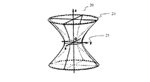
本発明の第1実施形態では、ピクセル・ビーム20は、図2に示されるような一葉双曲面により表現されても良く、一葉双曲面は、瞳孔24、及び、ピクセル12についての対物空間内のコンジュゲート25という2つの要素によりサポートされている。
In the first embodiment of the present invention, the
一葉双曲面は、光線のペンシル(光線束)の概念を支持し且つ物理的な光ビームの「エテンデュ(`etendue)」の概念、物理的な光ビームの断面を横切るエネルギの保存に結び付けられる概念と両立する線識面(a ruled surface)である。 The one-leaf hyperboloid supports the concept of a pencil of light and is associated with the concept of "etendue" of a physical light beam, the conservation of energy across the cross section of a physical light beam. It is a ruled surface that is compatible with.
図3に示されるように、一葉双曲面30は、ウェスト35と言及される最小セクションの基本領域を除いて、漸近円錐31,32にほぼ一致しており、ウェスト35は対物空間におけるコンジュゲート15に対応する。ライト・フィールド・カメラのようなプレノプティック・システムの場合、これは、複数の光線による空間サンプリングが実行される領域である。この領域内の一点に縮退する(degenerating)固有のコーンによるサンプリング空間は適切ではなく、なぜなら、ピクセル12の感度は、その表面において数十平方ミクロンで有意であり、円錐の先端のような無限に小さな表面しか有しない数学的な点によって表現することはできないからである。
As shown in FIG. 3, the one-
本発明の実施形態において、各々のピクセル・ビーム10,20,30は、瞳孔14,24の前方における瞳孔コンジュゲート15,35の位置及びサイズを規定する4つの独立パラメータzp,θx,θy,aと、瞳孔14,24の位置、向き及び半径を規定する6つの瞳孔パラメータx0,y0,z0,θx0,θy0,rとにより規定される。これら6つの瞳孔パラメータは、一葉双曲面によって表現される場合に、同じ瞳孔14,24を共有するピクセル・ビームの集まりに対して共通している。実際、ピクセル・ビームは、瞳孔14を介してピクセル12により検知される光学システム11の対物空間における光線束により占められる体積を表現し、すなわち、ピクセル12/瞳孔14,24の所与の組み合わせは、固有のピクセル・ビーム10,20,30に対応するが、複数の個々のピクセル・ビームは、同じ瞳孔14,24によってサポートされることが可能である。
In embodiments of the invention, each pixel beam 10, 20, 30 has four independent parameters z p , θ x , θ that define the position and size of the pupil conjugates 15, 35 in front of the
ピクセル・ビーム10,20,30を表現する一葉双曲線のパラメータが規定される座標系(x,y,z)の原点Oは、図1に示されるように瞳孔の中心に対応し、この場合において、z軸は瞳孔14,24の表面に対して垂直な方向を規定する。
The origin O of the coordinate system (x, y, z) that defines the parameters of the one-leaf hyperbola representing the pixel beams 10, 20, and 30 corresponds to the center of the pupil, as shown in Figure 1, in this case. The z-axis defines the direction perpendicular to the surfaces of
パラメータθx,θyは、エントランス瞳孔14の中心に対する主要光線方向を規定する。これらは、センサー13におけるピクセル12の位置、及び、光学系11の光学要素に依存する。より正確に言えば、パラメータθx,θyは、ピクセル12のコンジュゲート15についての、瞳孔14中心からの方向を規定するずれ角(shear angles)を表現する。
The parameters θ x and θ y define the main ray direction with respect to the center of the entrance pupil 14. These depend on the position of the
パラメータzpは、ピクセル・ビーム10,20,30のウェスト35、すなわち、ピクセル12のコンジュゲート15についての、z軸に沿った距離を表現する。
The parameter z p represents the distance along the z-axis for the
パラメータaは、ピクセル・ビーム10,20,30のウェスト35の半径を表現する。
The parameter a represents the radius of the
光のひずみ及びフィールド湾曲(field curvatures)がモデル化される場所である光学系11に関し、パラメータzp及びaは、パラメータ関数によりパラメータθx及びθyに依存することが可能である。
With respect to
4つの独立パラメータは、ピクセル12及びそのコンジュゲート15に関連する。
The four independent parameters relate to
ピクセル・ビーム10,20,30を規定する6つの補足的な瞳孔パラメータは、次のとおりである:
− r:瞳孔14,24の半径を表現する;
− x0,y0,z0:(x,y,z)座標系における瞳孔14,24の中心の座標を表現する;
− θx0,θy0:基準(x,y,z)座標系における瞳孔14,24の向きを表現する。
The six supplemental pupil parameters that define
− R: Represents the radii of
− X 0 , y 0 , z 0 : Represents the coordinates of the centers of
− Θ x0 , θ y0 : Represents the orientation of
これら6つの瞳孔パラメータは瞳孔14,24に関連している。べつのパラメータcが定義される。そのパラメータcは、瞳孔12及びそのコンジュゲート15に関連するパラメータzp及びaと、瞳孔14,24に関連するパラメータrとに依存する。パラメータcは、ピクセル・ビーム10,20,30の角度開口αを規定し、次式によって与えられる:tan(α)=a/c。
These six pupil parameters are associated with
パラメータcを表す式は次式によって与えられる:

ピクセル・ビーム10,20,30の境界を定める表面に属する点についての対物空間での座標(x,y,z)は、瞳孔14及びピクセルのコンジュゲート15に関する上記のパラメータ群の関数である。こうして、ピクセル・ビーム10,20,30を表現する一葉双曲面の生成を可能にする数式(2)は、次のとおりである:
ピクセル・ビーム10,20,30を表現する同じ双曲面のパラメータ方程式(3)は、次のとおりである:
νは、双曲線の生成からピクセル・ビーム10,20,30の生成を可能にする(x,y)平面内の角度であり、νは[0,2π]のインターバルで変化し、z∈[0,∞]は、瞳孔14、24の表面に垂直な方向を規定するz軸に沿った(z軸上の)座標である。数式(2)及び(3)は、瞳孔12及びそのコンジュゲート15の断面が円形であり、かつ、瞳孔14,24の断面も円形である、という仮定の下で記載されている。
The expression for the parameter c is given by:
The coordinates (x, y, z) in the objective space for points belonging to the surface that demarcate the pixel beams 10, 20, and 30 are functions of the above parameter set for the pupil 14 and the
The parameter equation (3) for the same hyperboloid representing the pixel beams 10, 20, and 30 is:
ν is the angle in the (x, y) plane that allows the generation of pixel beams 10, 20, 30 from the generation of the hyperbola, where ν varies at intervals of [0,2π] and z ∈ [0]. , ∞] are coordinates (on the z-axis) along the z-axis that define the direction perpendicular to the surfaces of the
光学取得システムのセンサーのピクセルと、光学取得システムの対物空間との間の対応関係に関する情報は、瞳孔14,24の前方にあるピクセル・コンジュゲート15,35の位置及びサイズを規定する4つの独立パラメータ(zp,θx,θy,a)と、ピクセル・ビームがパラメータ方程式で表現される場合に、瞳孔14,24の位置、方向及び半径を規定する6つの瞳孔パラメータx0,y0,z0,θx0,θy0,rとを含むパラメータ群の何れかの形式を取っても良い。
Information about the correspondence between the pixels of the sensor of the optical acquisition system and the objective space of the optical acquisition system is four independent that define the position and size of the pixel conjugates 15, 35 in front of the
従って、4Dライト・フィールド・データを処理する場合に使用されるように、光学取得システムにより取得される4Dライト・フィールド・データを表現するエピポーラ画像又は処理前画像に加えて、このパラメータ群が提供される。 Therefore, this set of parameters is provided in addition to the epipolar or unprocessed image representing the 4D light field data acquired by the optical acquisition system, as used when processing 4D light field data. Will be done.
本発明の第2実施形態では、ピクセル・ビーム40は、図4に示されるようなフロント・コーン(前方円錐)41F及びリア・コーン(後方円錐)41Rである部分的にオーバーラップする同軸上にあるコーンにより表現され、ピクセル・ビーム40は、ピクセル42についての対物空間におけるコンジュゲート45及び瞳孔44という2つの要素によりサポートされ、すなわち、対物空間の中でピクセルで撮像される表面によりサポートされる。
In a second embodiment of the invention, the pixel beam 40 is a partially overlapping coaxial with a front cone (front cone) 41 F and a rear cone (rear cone) 41 R as shown in FIG. Represented by the cone above, the pixel beam 40 is supported by two elements in the objective space for pixel 42: the conjugate 45 and the
フロント・コーン41Fは、ピクセル42及び瞳孔44により規定される凸状錐台の像(the image of a convex frustum)である。凸状錐台の先端は、光学取得システムのセンサーを超えた位置にある。この構成によれば、フロント・コーン41Fは光学取得システムの対物空間内で収束しており(一点に交わっており)、フロント・コーン41Fの先端は、ピクセル42のコンジュゲート即ちピクセル・ビーム40のウェストと瞳孔44との間にある。フロント・コーン41Fは、ピクセル42における瞳孔44に対する立体角から導出される。
The
リア・コーン41Rは、ピクセル42及び瞳孔44により規定される円錐の像であり、その先端は、瞳孔44と光学取得システムのセンサーとの間にある。この構成によれば、リア・コーン41Rの先端は、瞳孔44のウェスト45を超えた位置にある。リア・コーン41Rは、光学取得システムの対物空間の中で必ずしも収束しておらず、場合によっては、円筒状又は発散するコーンに縮退していても良い。後者の場合、発散するコーンの先端は、光学取得システムの像空間内にあり、すなわち、瞳孔44のエントランスの前方にある。
The
フロント・コーン41F及びリア・コーン41Rは、瞳孔44の中心とウェスト45の中心とを結ぶラインである同じ回転軸(the same revolution axis)を共有する。
The
コーンは、光線のペンシル(光線束)の概念を支持し、2つのコーンを組み合わせる場合に、物理的な光ビームの「エテンデュ」の概念、物理的な光ビームの断面を横切るエネルギの保存に結び付けられる概念と両立する線識面である。円錐の平面との交わりは双曲線のような円錐曲線であり、円錐曲線は複数の係数により特徴付けられることが可能である。先端を考察すると、コーンは3つの角度パラメータにより表現されても良く、その3つのパラメータは:コーンの回転軸から測った極角(a polar angle)(高々先端角に至るまでの角度)(up to the apex angle)と、2つの角度で与えられる回転軸の方向とである。 The cones support the concept of a pencil of rays and, when combining two cones, are linked to the concept of a physical light beam "etendu", the conservation of energy across a cross section of a physical light beam. It is a line-of-sight aspect that is compatible with the concept. The intersection of the cone with the plane is a conic section, such as a hyperbola, which can be characterized by multiple coefficients. Considering the tip, the cone may be represented by three angle parameters, the three parameters of which are: a polar angle as measured from the axis of rotation of the cone (up to the tip angle at most). to the apex angle) and the direction of the axis of rotation given at the two angles.
xyzを光学取得システムの座標系とし、zは光学取得システムの光学軸を示し、z>0を光学取得システムの対物空間とし、瞳孔44の中心をこの座標系の原点とする。
xyz is the coordinate system of the optical acquisition system, z is the optical axis of the optical acquisition system, z> 0 is the objective space of the optical acquisition system, and the center of the
光学取得システムの光学系は、光学取得システムの対物空間を、z∈[2f;+∞]のレンジから、z∈[-2f;-f]という光学取得システムの像空間へ撮像し、ここで、fは光学取得システムの光学系の焦点距離である。ピクセル・ビーム40のウェスト45及び瞳孔44の位置は、光学取得システムの校正により、光学座標システムの座標系xyzにおいて既知である。瞳孔44及びウェスト45は、平行であり、かつ、何れもz軸に垂直であるように仮定されている。
The optical system of the optical acquisition system images the objective space of the optical acquisition system from the range of z ∈ [2f; + ∞] to the image space of the optical acquisition system of z ∈ [-2f; -f]. , F are the focal distances of the optical system of the optical acquisition system. The positions of the
z’をピクセル・ビーム40の主要光線(the chief ray)と呼ぶことにする。主要光線は、瞳孔44の中心とピクセル・ビーム40のウェストの中心とを結ぶライン上にある。主要光線は、回転軸でもあり、かつ、ピクセル・ビーム40の対称軸でもある。従って、座標系xyz’において、ピクセル・ビーム40は回転体(a solid of revolution)である。
Let z'refer to the chief ray of the pixel beam 40. The main ray is on the line connecting the center of the
フロント・コーン41F及びリア・コーン41Rの双方の先端は、ピクセル・ビーム40の主要光線z’上に位置付けられる。薄レンズ近似の下では、これら2つの先端の座標は、次のようにして、光学取得システムの座標系xyzで算出され、ただし、光学取得システムのセンサーは、後方焦点面には位置付けられないことが仮定される:
リア・コーン41Rの先端のz座標zrearは、リア・コーン41Rが収束するコーンである場合には「正」であり、リア・コーン41Rが発散するコーンである場合には「負」であっても良い。ピクセル・ビームのピクセルのコンジュゲート45及び瞳孔44が同じサイズのものである場合、そのz座標は無限大であっても良い。
Z-coordinate z rear of the tip of the
光学取得システムのセンサーが後方焦点面に位置付けられる場合、W=+∞及びzw=+∞である。それらの比率は一定であるので、次式が成り立つ:
先端角は次式で与えられる:
ピクセル・ビームに関連するこれらの情報は、所与の光学取得システムに関連するメタデータである。これらは、例えば、光学取得システムに供給されるCD-ROM又はフラッシュ・ドライブに保存されるデータ・ファイルとして提供されても良い。ピクセル・ビームに関連する追加的な情報を含むデータ・ファイルは、光学取得システムの製造業者に帰属するサーバーからダウンロードされても良い。本発明の実施形態では、ピクセル・ビームに関連するこれらの追加的な情報は、光学取得システムにより取得される画像のヘッダに組み込まれても良い。 This information associated with the pixel beam is the metadata associated with a given optical acquisition system. These may be provided, for example, as data files stored on a CD-ROM or flash drive supplied to the optical acquisition system. Data files containing additional information related to the pixel beam may be downloaded from a server belonging to the manufacturer of the optical acquisition system. In embodiments of the invention, these additional pieces of information related to the pixel beam may be incorporated into the header of the image acquired by the optical acquisition system.
ピクセル・ビームに関連するこれらの情報についての知識は、専用のファイル・フォーマット(the proprietary file format)によらず、及び、処理される画像を捕捉するために使用される光学取得システムの特徴にもよらず、任意の光学取得システムにより取得される画像の処理を可能にする。 Knowledge of this information related to pixel beams does not depend on the proprietary file format and is also characteristic of the optical acquisition system used to capture the processed image. Regardless, it enables processing of images acquired by any optical acquisition system.
ピクセル・ビームに関連する情報についての知識は、専用のファイル・フォーマットによらず、及び、処理される画像を捕捉するために使用される光学取得システムの特徴にもよらず、任意の光学取得システムにより取得される画像の処理を可能にする。 Knowledge of information related to pixel beams is not dependent on the dedicated file format and the characteristics of the optical acquisition system used to capture the processed image, any optical acquisition system. Allows processing of the image acquired by.
図5は ピクセル・ビームに関連するボケを表現するデータを生成する本開示の実施形態による装置の具体例を示す概略的なブロック図である。 FIG. 5 is a schematic block diagram showing a specific example of the apparatus according to the embodiment of the present disclosure that generates data expressing the blur associated with the pixel beam.
装置500は、プロセッサ501と、ストレージ・ユニット502と、入力デバイス503と、ディスプレイ・デバイス504と、インターフェース・ユニット505とを含み、これらはバス506により接続されている。当然に、コンピュータ装置500の構成要素は、バス接続以外のコネクションで接続されていても良い。
The
プロセッサ501は装置500のオペレーションを制御する。ストレージ・ユニット502は、プロセッサ501により実行される第2光学系によりこれらのピクセル・ビームが撮像される場合に、第1光学系の対物空間を表現するピクセル・ビームを表すデータを生成することが可能な少なくとも1つのプログラム;及び、センサー13におけるピクセル12の位置に関するパラメータ、又は、光学取得システムの第1光学系及び第2光学系に関連するパラメータ、プロセッサ501により実行される計算により使用されるパラメータ、プロセッサ501により実行される計算の中間的なデータ等を含む様々なデータ; を保存する。プロセッサ501は、何らかの既知の適切なハードウェア若しくはソフトウェア又はハードウェア及びソフトウェアの組み合わせにより形成されても良い。例えば、プロセッサ501は、処理回路のような専用ハードウェアにより、或いは、メモリに保存されるプログラムを実行するCPU(中央処理ユニット)等のようなプログラム可能な処理ユニットにより形成されても良い。
ストレージ・ユニット502は、コンピュータ読み取り可能な方法で、プログラムやデータ等を保存することが可能な適切な任意の手段又はストレージにより形成されても良い。ストレージ・ユニット502の具体例は、半導体メモリ・デバイス等のような非一時的なコンピュータ読み取り可能な記憶媒体、及び、リード及びライト・ユニットに搭載される磁気的、光学的又は磁気-光学的な記録媒体を含む。プログラムは、図6を参照しながら説明されるような本開示の実施形態に従って、第2光学系を介するピクセル・ビームの像コンジュゲートにより、第1光学系の対物空間を表すピクセル・ビームの集合のうちのピクセル・ビームを表すデータを算出するプロセスを実行することを、プロセッサ501に実行させる。
The
コマンドを入力すること、光学系の対物空間における光線群により占められる体積を表現するパラメータを生成するために使用されるパラメータのユーザー選択を可能にすること等のために、ユーザーが使用するキーボードやポインティング・デバイス(例えば、マウス)等により、入力デバイス503は形成されても良い。出力デバイス504は、例えば、グラフィカル・ユーザー・インターフェース(GUI)、本開示の実施形態により生成される画像を表示するディスプレイ・デバイスにより形成されても良い。入力デバイス503及び出力デバイス504は、例えばタッチスクリーン・パネルにより一体的に形成されても良い。
Keyboards and keyboards used by users to enter commands, allow user selection of parameters used to generate parameters that represent the volume occupied by a group of rays in the objective space of an optical system, etc. The
インターフェース・ユニット505は、装置500と外部装置との間のインターフェースを提供する。インターフェース・ユニット505は、ケーブル又は無線通信により外部装置と通信しても良い。一実施形態において、外部装置は、実際のカメラのような光学取得システムであっても良い。
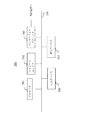
図6は、ピクセル・ビームに関連するボケを表現するデータを生成する本発明の実施形態によるプロセスを説明するためのフロー・チャートである。 FIG. 6 is a flow chart for illustrating a process according to an embodiment of the invention that produces data representing the blur associated with a pixel beam.
レンズにより生じる画像のうちピントが合っていない部分(焦点外れの部分)は、不鮮明になっている。そのような不鮮明性の美的品質は「ボケ」と呼ばれ、ボケは「レンズが光の焦点外れ点にする経路」として定義されても良い。レンズの収差及び開口形状の相違は、眼にとって心地良い方法で画像をぼかすことを、ある種のレンズ設計にはもたらすが、他のものには、心地良くない又は気が散る不鮮明性をもたらす。 The out-of-focus part (out-of-focus part) of the image generated by the lens is blurred. The aesthetic quality of such blur is called "bokeh", which may be defined as "the path the lens makes to the out-of-focus point of light". Lens aberrations and differences in aperture shape result in blurring the image in a way that is pleasing to the eye for some lens designs, but unpleasant or distracting blurring for others.
ライト・フィールド・コンテンツから画像又はビデオをレンダリングする場合に、ぼやけた審美性の観点から、従来の画像又はビデオにできるだけ近い画像を表示すること、すなわち、優れたボケ特性を有する画像を表示することは、興味深いことである。 When rendering an image or video from light field content, to display an image that is as close as possible to the traditional image or video from a blurry aesthetic point of view, i.e., to display an image with excellent blurring characteristics. Is interesting.
ライト・フィールド・コンテンツは、光学系の対物空間を規定するピクセル・ビームの集合によってサンプリングされても良い。本発明の実施形態は、光学デバイスにより直接的に取得されるライト・フィールド・コンテンツに限定されない。これらのコンテンツは、所与のシーンを記述するために、コンピュータにより完全に又は部分的にシミュレーションされるコンピュータ・グラフィックス・イメージ(CGI)であっても良い。ライト・フィールド・コンテンツの他のソースは、例えば、光学デバイス又はCGIから取得される色の度合い、ライト・フィールド・コンテンツ等のような修正される事後的に生成されるデータであっても良い。光学取得デバイスを利用して取得されるデータ及びCGIデータの双方の混合であるデータを有することも、映画業界において今や一般的である。センサーのピクセルは、コンピュータ生成シーン・システムによりシミュレーションされることが可能であり、拡張により、センサー全体が当該システムによりシミュレーションされることが可能であることが、理解されるべきである。これらから、「センサーのピクセル」又は「センサー」に関する何らかの言い回しは、光学取得デバイスに取り付けられた物理的な対象物、或いは、コンピュータ生成シーン・システムにより得られるシミュレーションされるエンティティであっても良いことが、理解される。 The light field content may be sampled by a set of pixel beams that define the objective space of the optical system. The embodiments of the present invention are not limited to the light field content directly acquired by the optical device. These contents may be computer graphics images (CGIs) that are fully or partially simulated by a computer to describe a given scene. Other sources of light field content may be modified post-generated data such as, for example, the degree of color obtained from an optical device or CGI, light field content, and the like. It is also now common in the film industry to have data that is a mixture of both data acquired using optical acquisition devices and CGI data. It should be understood that the pixels of a sensor can be simulated by a computer-generated scene system, and the extension allows the entire sensor to be simulated by that system. From these, any wording about "sensor pixels" or "sensors" may be a physical object attached to an optical acquisition device or a simulated entity obtained by a computer-generated scene system. However, it is understood.
ステップ600において、装置500のプロセッサ501は、p個の頂点を有する第1ポリゴンP1のように、ライト・フィールド・コンテンツを表現するピクセル・ビームの集合のピクセル・ビーム10,20,30,40,92のセクションS1をサンプリングする。セクションS1は、円、楕円、正方形などであっても良い。セクションS1及びポリゴンP1の具体例は、図7A-7Cに表現されている。図7Aにおいて、ピクセル・ビーム10,20,30,40,92のセクションS1をサンプリングするポリゴンP1は6つの頂点を有する。図7Bにおいては、ピクセル・ビーム10,20,30,40,92のセクションS1をサンプリングするポリゴンP1は8つの頂点を有する。図7Cにおいては、ピクセル・ビーム10,20,30,40,92のセクションS1をサンプリングするポリゴンP1は16個の頂点を有し、ピクセル・ビーム10,20,30,40,62のセクションS1とほぼ合わせることが可能である。
In
ステップ602において、装置500のプロセッサ501は、n個の頂点を有する第2ポリゴンP2のように、ライト・フィールド・コンテンツを表現するピクセル・ビームの集合のピクセル・ビーム10,20,30,40,92の瞳孔S2をサンプリングする。瞳孔S2は、円、楕円、正方形などであっても良い。瞳孔S2及びポリゴンP2の具体例は、図8A-8Fに表現されている。図8Aにおいて、ピクセル・ビーム10,20,30,40,92の瞳孔S2をサンプリングするポリゴンP2は4つの頂点を有する。図8Bにおいて、ピクセル・ビーム10,20,30,40,92の瞳孔S2をサンプリングするポリゴンP2は5つの頂点を有する。図8Cにおいて、ピクセル・ビーム10,20,30,40,92の瞳孔S2をサンプリングするポリゴンP2は6つの頂点を有する。図8Dにおいて、ピクセル・ビーム10,20,30,40,92の瞳孔S2をサンプリングするポリゴンP2は8つの頂点を有する。図8Eにおいて、ピクセル・ビーム10,20,30,40,92の瞳孔S2をサンプリングするポリゴンP2は12個の頂点を有する。図8Fにおいては、ピクセル・ビーム10,20,30,40,92のセクションS1をサンプリングするポリゴンP2は16個の頂点を有し、ピクセル・ビーム10,20,30,40,62の瞳孔92とほぼ合わせることが可能である。
In
本発明の実施形態による方法の複雑さは、第1ポリゴンS1及び第2ポリゴンS2の頂点の個数とともに線形に増えることが分かる。処理の最中における装置500のプロセッサ501及びストレージ・ユニット502のアライメントの問題に関し、p及びnは4の倍数であることが好ましい。ポリゴンP1及びP2の頂点の数は、装置500のユーザーにより選択されても良いし、装置500の入力デバイス503によりボケを表現するデータを生成するために使用されるパラメータとして装置500に提供されても良い。
It can be seen that the complexity of the method according to the embodiment of the present invention increases linearly with the number of vertices of the first polygon S1 and the second polygon S2. With respect to the alignment problem of
ピクセル・ビームに関連するボケを表現するデータを生成する方法の第1実施形態では、考察されるピクセル・ビーム10,20,30,40は、光学系の対物空間を表現するピクセル・ビームの集合に帰属する(不図示)。この第1実施形態では、ピクセル・ビーム10,20,30,40のセクションS1は、ピクセル15,25,35,45のコンジュゲートに対応し;瞳孔S2はエントランス瞳孔であり、瞳孔14,24,44に対応する。
In the first embodiment of the method of generating data representing the blur associated with a pixel beam, the pixel beams 10, 20, 30, 40 considered are a set of pixel beams representing the objective space of the optical system. Belongs to (not shown). In this first embodiment, sections S1 of pixel beams 10, 20, 30, 40 correspond to conjugates of
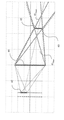
ピクセル・ビームに関連するボケを表現するデータを生成する方法の第2実施形態では、考察されるピクセル・ビーム92は、図9に示されるように、第2光学系91を介して第1光学系(不図示)の対物空間を表現するピクセル・ビームの集合に帰属するピクセル・ビーム10,20,30,40のコンジュゲートである。以下の例では、ピクセル・ビーム10,20,30,40,92は、一葉双曲面により表現されている。この第2実施形態では、ピクセル・ビーム92のセクションS1は、所与のピクセル・ビーム10,20,30,40と平面との交わりについての、第2光学系91を介するコンジュゲートに対応し;瞳孔S2は第2光学系91のエグジット瞳孔(an exit pupil)に対応する。
In the second embodiment of the method of generating data representing the blur associated with a pixel beam, the
図6に戻り、ステップ603において、装置500のプロセッサ501は、第1ポリゴンP1のp個の頂点と第2ポリゴンP2のn個の頂点とを共に結ぶ光線群を算出する。
Returning to FIG. 6, in
ピクセル・ビームに関連するボケを表現するデータを生成する方法の第1実施形態に対応する、光学系の対物空間に位置付けられるピクセル・ビーム10,20,30,40の場合、第1ポリゴンP1の頂点を、第2ポリゴンP2の頂点に結ぶp×n個の線が存在する。 In the case of the pixel beams 10, 20, 30, and 40 positioned in the objective space of the optical system corresponding to the first embodiment of the method of generating the data expressing the blur related to the pixel beam, the first polygon P1. There are p × n lines connecting the vertices to the vertices of the second polygon P2.
ピクセル・ビーム92又は画像ピクセル・ビームの場合:これは、ピクセル・ビームに関連するボケを表現するデータを生成する方法の第2実施形態に対応し、より具体的に言えば、ピクセル・ビーム10,20,30,40,92は2つのオーバーラップするコーンの統合に対応する場合であり、その場合、第1ポリゴンP1の頂点を、第2ポリゴンP2の頂点に結ぶn×2p個の線が存在する。
For
ステップ604において、プロセッサ501は、第1ポリゴンP1のp個の頂点及び第2ポリゴンP2のn個の頂点を結ぶ線と、表面との交わりを算出する。
In
ピクセル・ビームに関連するボケを表現するデータを生成する方法の第1実施形態においては、その表面は、光学系の焦点面に対応する。 In the first embodiment of the method of generating data representing the blur associated with a pixel beam, the surface corresponds to the focal plane of the optical system.
ピクセル・ビームに関連するボケを表現するデータを生成する方法の第2実施形態においては、その表面は、第2光学系91に関連するセンサーに対応する。 In the second embodiment of the method of generating data representing the blur associated with the pixel beam, the surface corresponds to the sensor associated with the second optical system 91.
より具体的には、表面は、ピクセル・ビームのセクションの算出が提供される場合には焦点面に対応し、或いは、カメラでピクセル・ビームのセクションを撮像する場合にはセンサーに対応して良い。 More specifically, the surface may correspond to the focal plane if the calculation of the pixel beam section is provided, or to the sensor if the camera captures the pixel beam section. ..
ステップ605において、装置500のプロセッサ501は、第1ポリゴンP1のp個の頂点及び第2ポリゴンS2のn個の頂点を結ぶ線の、表面との交わりに適合する凸状包絡線を算出する。凸状包絡線は、ピクセル・ビーム10,20,30,40,92に関連するボケに対応する。ステップ605の間に算出される凸状包絡線を表すパラメータは、更なる利用のために装置500のストレージ・ユニット502に保存され、更なる利用は、例えば、ボケに関連するデータが算出されているピクセル・ビームの集合によりサンプリングされるライト・フィールド・コンテンツをレンダリングすること等である。交わりが多いほど、豊富な審美的なボケとなる。
In step 605, the
以上、本発明は特定の実施形態を参照しながら説明されてきたが、本発明は特定の実施形態には限定されず、本発明の範囲内にある修正は、当業者にとって明らかであろう。 Although the present invention has been described above with reference to specific embodiments, the present invention is not limited to the specific embodiments, and modifications within the scope of the present invention will be obvious to those skilled in the art.
上記の例示的な実施形態を参照した当業者にとって、他の多くの修正及び変形は自ずと示唆され、上記の実施形態は単なる例示として与えられているに過ぎず、本発明の範囲を限定するようには意図されておらず、本発明は添付の特許請求の範囲によって専ら決定される。特に、様々な実施形態の様々な特徴は、適切である限り可換である。
なお、上述の実施形態の一部又は全部は、以下の付記のように記載され得るが、以下には限定されない。
(付記1)
光学系の瞳孔と、前記光学系に関連するセンサーの少なくとも1つのピクセルについての、前記光学系の対物空間におけるコンジュゲートとを通る光線群により占められる前記光学系の対物空間における或る体積に関連するボケを表すデータを生成するためにコンピュータにより実行される方法であって、前記体積は、ピクセル・ビームと言及される光線群により占められ、前記ピクセル・ビームの集合によりライト・フィールド・コンテンツが表現され、当該方法は、
前記ピクセル・ビームのセクションをサンプリングする第1ポリゴンの頂点を、前記瞳孔のサンプリングを表現する第2ポリゴンの頂点に結ぶ線の、第1表面との一群の交わりによる凸状包絡線に対応する、前記ピクセル・ビームに関連するボケを表すデータを生成するステップ
を有する方法。
(付記2)
前記ピクセル・ビームのセクションは前記センサーのピクセルのコンジュゲートに対応し、前記瞳孔は前記光学系のエントランス瞳孔に対応し、前記第1表面は前記光学系の焦点面に対応する、付記1に記載の方法。
(付記3)
前記ピクセル・ビームのセクションが、前記ピクセル・ビームと或る平面との交わりについての他の光学系を介するコンジュゲートに対応し、前記瞳孔は前記光学系のエグジット瞳孔に対応し、前記第1表面は前記光学系に関連するセンサーに対応する、付記1に記載の方法。
(付記4)
前記第1ポリゴンはp個の頂点を有し、前記第2ポリゴンはn個の頂点を有し、前記第1ポリゴンのp個の頂点を前記第2ポリゴンのn個の頂点に結ぶ線の個数は、n×pの倍数である、付記1ないし3のうちの何れか一項に記載の方法。
(付記5)
光学系の瞳孔と、前記光学系に関連するセンサーの少なくとも1つのピクセルについての、前記光学系の対物空間におけるコンジュゲートとを通る光線群により占められる前記光学系の対物空間における或る体積に関連するボケを表すデータを生成する装置であって、前記体積は、ピクセル・ビームと言及される光線群により占められ、前記ピクセル・ビームの集合によりライト・フィールド・コンテンツが表現され、当該装置は
前記ピクセル・ビームのセクションをサンプリングする第1ポリゴンの頂点を、前記瞳孔のサンプリングを表現する第2ポリゴンの頂点に結ぶ線の、第1表面との一群の交わりによる凸状包絡線に対応する、前記ピクセル・ビームに関連するボケを表すデータを生成する;
ように構成されるプロセッサを有する装置。
(付記6)
前記ピクセル・ビームのセクションは前記センサーのピクセルのコンジュゲートに対応し、前記瞳孔は前記光学系のエントランス瞳孔に対応し、前記第1表面は前記光学系の焦点面に対応する、付記5に記載の装置。
(付記7)
前記ピクセル・ビームのセクションが、前記ピクセル・ビームと或る平面との交わりについての他の光学系を介するコンジュゲートに対応し、前記瞳孔は前記光学系のエグジット瞳孔に対応し、前記第1表面は前記光学系に関連するセンサーに対応する、付記5に記載の装置。
(付記8)
前記第1ポリゴンはp個の頂点を有し、前記第2ポリゴンはn個の頂点を有し、前記第1ポリゴンのp個の頂点を前記第2ポリゴンのn個の頂点に結ぶ線の個数は、n×pの倍数である、付記5ないし7のうちの何れか一項に記載の装置。
(付記9)
光学系の瞳孔と、前記光学系に関連するセンサーの少なくとも1つのピクセルについての、前記光学系の対物空間におけるコンジュゲートとを通る光線群により占められる光学系の対物空間における或る体積に関連するボケをレンダリングするデバイスであって、前記体積は、付記1ないし4のうち何れか一項に記載の方法により取得されるピクセル・ビームと言及される光線群により占められる、デバイス。
(付記10)
プログラムがプロセッサにより実行される場合に、付記1ないし4のうち何れか一項に従って、ボケを表すデータを生成する方法を実現するプログラム・コード命令を有することを特徴とするコンピュータ・プログラム。
(付記11)
付記1ないし4のうち何れか一項に従って、ボケを表すデータを生成する方法をプロセッサに実行させる命令を保存したプロセッサ読み取り可能な媒体。
(付記12)
プログラムがコンピューティング・デバイスで実行される場合に、付記1ないし4のうち何れか一項に従って、ボケを表すデータを生成する方法を実行するためのプログラム・コードの命令を担う非一時的な記憶媒体。
Many other modifications and modifications are naturally suggested to those skilled in the art with reference to the above exemplary embodiments, and the above embodiments are provided merely as examples and limit the scope of the invention. The present invention is solely determined by the appended claims. In particular, the various features of the various embodiments are commutative as long as appropriate.
In addition, a part or all of the above-mentioned embodiment may be described as the following appendix, but is not limited to the following.
(Appendix 1)
Related to a volume in the optical system objective space occupied by a group of light rays passing through the optical system pupil and the conjugate in the optical system objective space for at least one pixel of the sensor associated with the optical system. A method performed by a computer to generate data that represents the blur, the volume is occupied by a group of rays referred to as pixel beams, and the set of pixel beams provides light field content. Expressed and the method is
Corresponds to the convex envelope of the line connecting the vertices of the first polygon sampling the section of the pixel beam to the vertices of the second polygon representing the sampling of the pupil, due to the intersection of a group of first surfaces. Steps to generate data representing the blur associated with the pixel beam
How to have.
(Appendix 2)
The section of the pixel beam corresponds to the conjugate of the pixels of the sensor, the pupil corresponds to the entrance pupil of the optical system, and the first surface corresponds to the focal plane of the optical system, according to Appendix 1. the method of.
(Appendix 3)
The section of the pixel beam corresponds to a conjugate via another optical system for the intersection of the pixel beam with a plane, the pupil corresponds to the exit pupil of the optical system, and the first surface. 1 is the method according to Appendix 1, which corresponds to the sensor related to the optical system.
(Appendix 4)
The first polygon has p vertices, the second polygon has n vertices, and the number of lines connecting the p vertices of the first polygon to the n vertices of the second polygon. Is a multiple of n × p, the method according to any one of Supplementary note 1 to 3.
(Appendix 5)
Related to a volume in the optical system objective space occupied by a group of light rays passing through the optical system pupil and the conjugate in the optical system objective space for at least one pixel of the sensor associated with the optical system. A device that generates data representing blurring, wherein the volume is occupied by a group of rays referred to as pixel beams, and the set of the pixel beams represents light field content, which the device is.
Corresponds to the convex envelope of the line connecting the vertices of the first polygon sampling the section of the pixel beam to the vertices of the second polygon representing the sampling of the pupil, due to the intersection of a group of first surfaces. Generates data representing the blur associated with the pixel beam;
A device having a processor configured as such.
(Appendix 6)
The section of the pixel beam corresponds to the conjugate of the pixels of the sensor, the pupil corresponds to the entrance pupil of the optical system, and the first surface corresponds to the focal plane of the optical system, according to
(Appendix 7)
The section of the pixel beam corresponds to a conjugate via another optical system for the intersection of the pixel beam with a plane, the pupil corresponds to the exit pupil of the optical system, and the first surface. 5 is the apparatus according to
(Appendix 8)
The first polygon has p vertices, the second polygon has n vertices, and the number of lines connecting the p vertices of the first polygon to the n vertices of the second polygon. Is the device according to any one of
(Appendix 9)
It is related to a volume in the optical system objective space occupied by a group of light rays passing through the optical system pupil and the conjugate in the optical system objective space for at least one pixel of the sensor associated with the optical system. A device that renders blur, wherein the volume is occupied by a group of rays referred to as a pixel beam obtained by the method according to any one of Supplementary Notes 1 to 4.
(Appendix 10)
A computer program comprising a program code instruction that implements a method of generating data representing blur according to any one of Supplementary Provisions 1 to 4, when the program is executed by a processor.
(Appendix 11)
A processor-readable medium that stores instructions that cause the processor to execute a method of generating data representing blur in accordance with any one of Supplements 1 to 4.
(Appendix 12)
A non-temporary memory that, when the program is run on a computing device, is responsible for commanding the program code to perform a method of generating data representing blur according to any one of appendices 1-4. Medium.
Claims (12)
前記ピクセル・ビームのセクションをサンプリングする第1ポリゴンの頂点を、前記瞳孔のサンプリングを表現する第2ポリゴンの頂点に結ぶ線の、第1表面との一群の交わりによる凸状包絡線に対応する、前記ピクセル・ビームに関連するボケを表すデータを生成するステップ;
を有する方法。 Related to a volume in the optical system objective space occupied by a group of light rays passing through the optical system pupil and the conjugate in the optical system objective space for at least one pixel of the sensor associated with the optical system. A method performed by a computer to generate data that represents the blur, the volume is occupied by a group of rays referred to as pixel beams, and the set of pixel beams provides light field content. Expressed and the method is:
Corresponds to the convex envelope of the line connecting the vertices of the first polygon sampling the section of the pixel beam to the vertices of the second polygon representing the sampling of the pupil, due to the intersection of a group of first surfaces. Steps to generate data representing the blur associated with the pixel beam;
How to have.
前記ピクセル・ビームのセクションをサンプリングする第1ポリゴンの頂点を、前記瞳孔のサンプリングを表現する第2ポリゴンの頂点に結ぶ線の、第1表面との一群の交わりによる凸状包絡線に対応する、前記ピクセル・ビームに関連するボケを表すデータを生成する;
ように構成されるプロセッサを有する装置。 Related to a volume in the optical system objective space occupied by a group of light rays passing through the optical system pupil and the conjugate in the optical system objective space for at least one pixel of the sensor associated with the optical system. A device that produces data representing blurring, the volume of which is occupied by a group of rays referred to as pixel beams, and the set of the pixel beams represents light field content, which the device is:
Corresponds to the convex envelope of the line connecting the vertices of the first polygon sampling the section of the pixel beam to the vertices of the second polygon representing the sampling of the pupil, due to the intersection of a group of first surfaces. Generates data representing the blur associated with the pixel beam;
A device having a processor configured as such.
Applications Claiming Priority (2)
| Application Number | Priority Date | Filing Date | Title |
|---|---|---|---|
| EP16306082.5A EP3288253A1 (en) | 2016-08-25 | 2016-08-25 | Method and apparatus for generating data representative of a bokeh associated to light-field data |
| EP16306082.5 | 2016-08-25 |
Publications (3)
| Publication Number | Publication Date |
|---|---|
| JP2018033133A JP2018033133A (en) | 2018-03-01 |
| JP2018033133A5 JP2018033133A5 (en) | 2020-09-24 |
| JP6971084B2 true JP6971084B2 (en) | 2021-11-24 |
Family
ID=56883744
Family Applications (1)
| Application Number | Title | Priority Date | Filing Date |
|---|---|---|---|
| JP2017156980A Active JP6971084B2 (en) | 2016-08-25 | 2017-08-16 | Methods and devices for generating data that expresses the blur associated with light field data |
Country Status (5)
| Country | Link |
|---|---|
| US (1) | US10475163B2 (en) |
| EP (2) | EP3288253A1 (en) |
| JP (1) | JP6971084B2 (en) |
| KR (1) | KR102478989B1 (en) |
| CN (1) | CN107786808B (en) |
Families Citing this family (4)
| Publication number | Priority date | Publication date | Assignee | Title |
|---|---|---|---|---|
| CN104081414B (en) * | 2011-09-28 | 2017-08-01 | Fotonation开曼有限公司 | System and method for coding and decoding light field image file |
| EP3270589A1 (en) * | 2016-07-11 | 2018-01-17 | Thomson Licensing | An apparatus and a method for generating data representative of a pixel beam |
| US11328437B2 (en) | 2020-09-08 | 2022-05-10 | Weta Digital Limited | Method for emulating defocus of sharp rendered images |
| US11308586B2 (en) * | 2020-09-08 | 2022-04-19 | Unity Technologies Sf | Method for applying a vignette effect to rendered images |
Family Cites Families (22)
| Publication number | Priority date | Publication date | Assignee | Title |
|---|---|---|---|---|
| US8400454B2 (en) | 2005-03-30 | 2013-03-19 | Ati Technologies, Inc. | System and method for creating motion blur |
| JP4826152B2 (en) * | 2005-06-23 | 2011-11-30 | 株式会社ニコン | Image composition method and imaging apparatus |
| EP2502115A4 (en) | 2009-11-20 | 2013-11-06 | Pelican Imaging Corp | Capturing and processing of images using monolithic camera array with heterogeneous imagers |
| KR101661166B1 (en) | 2010-06-14 | 2016-09-29 | 연세대학교 산학협력단 | Method and apparatus for ray tracing in three-dimension image system |
| JP2012044564A (en) * | 2010-08-20 | 2012-03-01 | Sanyo Electric Co Ltd | Imaging apparatus |
| JP5623313B2 (en) * | 2011-03-10 | 2014-11-12 | キヤノン株式会社 | Imaging apparatus and imaging optical system |
| EP2817955B1 (en) * | 2012-02-21 | 2018-04-11 | FotoNation Cayman Limited | Systems and methods for the manipulation of captured light field image data |
| US8995785B2 (en) | 2012-02-28 | 2015-03-31 | Lytro, Inc. | Light-field processing and analysis, camera control, and user interfaces and interaction on light-field capture devices |
| GB2503656B (en) * | 2012-06-28 | 2014-10-15 | Canon Kk | Method and apparatus for compressing or decompressing light field images |
| JP6335423B2 (en) * | 2012-08-31 | 2018-05-30 | キヤノン株式会社 | Information processing apparatus and information processing method |
| US9092890B2 (en) * | 2012-12-20 | 2015-07-28 | Ricoh Company, Ltd. | Occlusion-aware reconstruction of three-dimensional scenes from light field images |
| JP6381273B2 (en) | 2014-05-02 | 2018-08-29 | キヤノン株式会社 | Imaging apparatus, image processing system, and control method thereof |
| US8988317B1 (en) * | 2014-06-12 | 2015-03-24 | Lytro, Inc. | Depth determination for light field images |
| JP6548367B2 (en) * | 2014-07-16 | 2019-07-24 | キヤノン株式会社 | Image processing apparatus, imaging apparatus, image processing method and program |
| CN105635530B (en) * | 2014-11-03 | 2019-04-30 | 北京蚁视科技有限公司 | Optical field imaging system |
| EP3026884A1 (en) * | 2014-11-27 | 2016-06-01 | Thomson Licensing | Plenoptic camera comprising a light emitting device |
| FR3030066B1 (en) * | 2014-12-16 | 2017-12-22 | Commissariat Energie Atomique | STRUCTURED LIGHT PROJECTOR AND THREE-DIMENSIONAL SCANNER HAVING SUCH A PROJECTOR |
| US9544514B2 (en) * | 2015-03-06 | 2017-01-10 | Ricoh Company, Ltd. | Automatic adjustment of light field imaging systems for resolution enhancement |
| JP2017021425A (en) * | 2015-07-07 | 2017-01-26 | キヤノン株式会社 | Image generation device, image generation method and image generation program |
| US10218968B2 (en) * | 2016-03-05 | 2019-02-26 | Maximilian Ralph Peter von und zu Liechtenstein | Gaze-contingent display technique |
| US10122994B2 (en) * | 2016-11-11 | 2018-11-06 | Disney Enterprises, Inc. | Object reconstruction from dense light fields via depth from gradients |
| US9900510B1 (en) * | 2016-12-08 | 2018-02-20 | Lytro, Inc. | Motion blur for light-field images |
-
2016
- 2016-08-25 EP EP16306082.5A patent/EP3288253A1/en not_active Withdrawn
-
2017
- 2017-08-04 EP EP17184960.7A patent/EP3291535A1/en active Pending
- 2017-08-16 JP JP2017156980A patent/JP6971084B2/en active Active
- 2017-08-22 US US15/683,207 patent/US10475163B2/en active Active
- 2017-08-22 KR KR1020170106078A patent/KR102478989B1/en active IP Right Grant
- 2017-08-25 CN CN201710740619.XA patent/CN107786808B/en active Active
Also Published As
| Publication number | Publication date |
|---|---|
| CN107786808B (en) | 2022-04-01 |
| JP2018033133A (en) | 2018-03-01 |
| US10475163B2 (en) | 2019-11-12 |
| CN107786808A (en) | 2018-03-09 |
| EP3291535A1 (en) | 2018-03-07 |
| KR20180023835A (en) | 2018-03-07 |
| EP3288253A1 (en) | 2018-02-28 |
| KR102478989B1 (en) | 2022-12-19 |
| US20180061016A1 (en) | 2018-03-01 |
Similar Documents
| Publication | Publication Date | Title |
|---|---|---|
| JP6971084B2 (en) | Methods and devices for generating data that expresses the blur associated with light field data | |
| JP2018531448A6 (en) | Apparatus and method for calibrating an optical capture system | |
| JP2018531448A (en) | Apparatus and method for calibrating an optical capture system | |
| RU2729698C2 (en) | Apparatus and method for encoding an image captured by an optical system for acquiring data | |
| KR102253320B1 (en) | Method for displaying 3 dimension image in integral imaging microscope system, and integral imaging microscope system implementing the same | |
| KR102454773B1 (en) | An apparatus and a method for generating data representative of a pixel beam | |
| CN108353120B (en) | Apparatus and method for generating data representing a pixel beam | |
| CN109565583B (en) | Method and apparatus for generating data representing a pixel beam |
Legal Events
| Date | Code | Title | Description |
|---|---|---|---|
| RD03 | Notification of appointment of power of attorney |
Free format text: JAPANESE INTERMEDIATE CODE: A7423 Effective date: 20181220 |
|
| RD04 | Notification of resignation of power of attorney |
Free format text: JAPANESE INTERMEDIATE CODE: A7424 Effective date: 20181227 |
|
| A711 | Notification of change in applicant |
Free format text: JAPANESE INTERMEDIATE CODE: A711 Effective date: 20191111 |
|
| A521 | Request for written amendment filed |
Free format text: JAPANESE INTERMEDIATE CODE: A523 Effective date: 20200813 |
|
| A621 | Written request for application examination |
Free format text: JAPANESE INTERMEDIATE CODE: A621 Effective date: 20200813 |
|
| A977 | Report on retrieval |
Free format text: JAPANESE INTERMEDIATE CODE: A971007 Effective date: 20210906 |
|
| TRDD | Decision of grant or rejection written | ||
| A01 | Written decision to grant a patent or to grant a registration (utility model) |
Free format text: JAPANESE INTERMEDIATE CODE: A01 Effective date: 20211011 |
|
| A61 | First payment of annual fees (during grant procedure) |
Free format text: JAPANESE INTERMEDIATE CODE: A61 Effective date: 20211101 |
|
| R150 | Certificate of patent or registration of utility model |
Ref document number: 6971084 Country of ref document: JP Free format text: JAPANESE INTERMEDIATE CODE: R150 |