JP6971083B2 - A stylus with variable transmit signal strength and a sensor to detect such a stylus - Google Patents
A stylus with variable transmit signal strength and a sensor to detect such a stylus Download PDFInfo
- Publication number
- JP6971083B2 JP6971083B2 JP2017156317A JP2017156317A JP6971083B2 JP 6971083 B2 JP6971083 B2 JP 6971083B2 JP 2017156317 A JP2017156317 A JP 2017156317A JP 2017156317 A JP2017156317 A JP 2017156317A JP 6971083 B2 JP6971083 B2 JP 6971083B2
- Authority
- JP
- Japan
- Prior art keywords
- stylus
- signal
- sensor
- intensity
- electrode
- Prior art date
- Legal status (The legal status is an assumption and is not a legal conclusion. Google has not performed a legal analysis and makes no representation as to the accuracy of the status listed.)
- Active
Links
Images


Classifications
-
- G—PHYSICS
- G06—COMPUTING; CALCULATING OR COUNTING
- G06F—ELECTRIC DIGITAL DATA PROCESSING
- G06F3/00—Input arrangements for transferring data to be processed into a form capable of being handled by the computer; Output arrangements for transferring data from processing unit to output unit, e.g. interface arrangements
- G06F3/01—Input arrangements or combined input and output arrangements for interaction between user and computer
- G06F3/03—Arrangements for converting the position or the displacement of a member into a coded form
- G06F3/033—Pointing devices displaced or positioned by the user, e.g. mice, trackballs, pens or joysticks; Accessories therefor
- G06F3/0354—Pointing devices displaced or positioned by the user, e.g. mice, trackballs, pens or joysticks; Accessories therefor with detection of 2D relative movements between the device, or an operating part thereof, and a plane or surface, e.g. 2D mice, trackballs, pens or pucks
- G06F3/03545—Pens or stylus
-
- G—PHYSICS
- G06—COMPUTING; CALCULATING OR COUNTING
- G06F—ELECTRIC DIGITAL DATA PROCESSING
- G06F3/00—Input arrangements for transferring data to be processed into a form capable of being handled by the computer; Output arrangements for transferring data from processing unit to output unit, e.g. interface arrangements
- G06F3/01—Input arrangements or combined input and output arrangements for interaction between user and computer
- G06F3/03—Arrangements for converting the position or the displacement of a member into a coded form
- G06F3/033—Pointing devices displaced or positioned by the user, e.g. mice, trackballs, pens or joysticks; Accessories therefor
- G06F3/038—Control and interface arrangements therefor, e.g. drivers or device-embedded control circuitry
- G06F3/0383—Signal control means within the pointing device
-
- G—PHYSICS
- G06—COMPUTING; CALCULATING OR COUNTING
- G06F—ELECTRIC DIGITAL DATA PROCESSING
- G06F3/00—Input arrangements for transferring data to be processed into a form capable of being handled by the computer; Output arrangements for transferring data from processing unit to output unit, e.g. interface arrangements
- G06F3/01—Input arrangements or combined input and output arrangements for interaction between user and computer
- G06F3/03—Arrangements for converting the position or the displacement of a member into a coded form
- G06F3/041—Digitisers, e.g. for touch screens or touch pads, characterised by the transducing means
- G06F3/044—Digitisers, e.g. for touch screens or touch pads, characterised by the transducing means by capacitive means
- G06F3/0441—Digitisers, e.g. for touch screens or touch pads, characterised by the transducing means by capacitive means using active external devices, e.g. active pens, for receiving changes in electrical potential transmitted by the digitiser, e.g. tablet driving signals
-
- G—PHYSICS
- G06—COMPUTING; CALCULATING OR COUNTING
- G06F—ELECTRIC DIGITAL DATA PROCESSING
- G06F3/00—Input arrangements for transferring data to be processed into a form capable of being handled by the computer; Output arrangements for transferring data from processing unit to output unit, e.g. interface arrangements
- G06F3/01—Input arrangements or combined input and output arrangements for interaction between user and computer
- G06F3/03—Arrangements for converting the position or the displacement of a member into a coded form
- G06F3/041—Digitisers, e.g. for touch screens or touch pads, characterised by the transducing means
- G06F3/044—Digitisers, e.g. for touch screens or touch pads, characterised by the transducing means by capacitive means
- G06F3/0442—Digitisers, e.g. for touch screens or touch pads, characterised by the transducing means by capacitive means using active external devices, e.g. active pens, for transmitting changes in electrical potential to be received by the digitiser
-
- G—PHYSICS
- G06—COMPUTING; CALCULATING OR COUNTING
- G06F—ELECTRIC DIGITAL DATA PROCESSING
- G06F2203/00—Indexing scheme relating to G06F3/00 - G06F3/048
- G06F2203/038—Indexing scheme relating to G06F3/038
- G06F2203/0384—Wireless input, i.e. hardware and software details of wireless interface arrangements for pointing devices
-
- G—PHYSICS
- G06—COMPUTING; CALCULATING OR COUNTING
- G06F—ELECTRIC DIGITAL DATA PROCESSING
- G06F2203/00—Indexing scheme relating to G06F3/00 - G06F3/048
- G06F2203/041—Indexing scheme relating to G06F3/041 - G06F3/045
- G06F2203/04101—2.5D-digitiser, i.e. digitiser detecting the X/Y position of the input means, finger or stylus, also when it does not touch, but is proximate to the digitiser's interaction surface and also measures the distance of the input means within a short range in the Z direction, possibly with a separate measurement setup
-
- G—PHYSICS
- G06—COMPUTING; CALCULATING OR COUNTING
- G06F—ELECTRIC DIGITAL DATA PROCESSING
- G06F2203/00—Indexing scheme relating to G06F3/00 - G06F3/048
- G06F2203/041—Indexing scheme relating to G06F3/041 - G06F3/045
- G06F2203/04108—Touchless 2D- digitiser, i.e. digitiser detecting the X/Y position of the input means, finger or stylus, also when it does not touch, but is proximate to the digitiser's interaction surface without distance measurement in the Z direction
-
- G—PHYSICS
- G06—COMPUTING; CALCULATING OR COUNTING
- G06F—ELECTRIC DIGITAL DATA PROCESSING
- G06F3/00—Input arrangements for transferring data to be processed into a form capable of being handled by the computer; Output arrangements for transferring data from processing unit to output unit, e.g. interface arrangements
- G06F3/01—Input arrangements or combined input and output arrangements for interaction between user and computer
- G06F3/03—Arrangements for converting the position or the displacement of a member into a coded form
- G06F3/041—Digitisers, e.g. for touch screens or touch pads, characterised by the transducing means
- G06F3/0416—Control or interface arrangements specially adapted for digitisers
- G06F3/04162—Control or interface arrangements specially adapted for digitisers for exchanging data with external devices, e.g. smart pens, via the digitiser sensing hardware
Landscapes
- Engineering & Computer Science (AREA)
- General Engineering & Computer Science (AREA)
- Theoretical Computer Science (AREA)
- Human Computer Interaction (AREA)
- Physics & Mathematics (AREA)
- General Physics & Mathematics (AREA)
- Measurement Of Length, Angles, Or The Like Using Electric Or Magnetic Means (AREA)
- Position Input By Displaying (AREA)
Description
本開示は、タブレット式コンピューティング装置、またはコンピューティング装置に付帯したタブレット周辺装置などの、電子装置によるスタイラスの検出能力の向上に関する。 The present disclosure relates to an improvement in the ability of an electronic device to detect a stylus, such as a tablet computing device or a tablet peripheral device attached to the computing device.
(関連技術の説明)
今日のスタイラスには、タブレットまたは携帯電話などの電子装置との双方向通信(すなわち、信号を送受信すること)を容易にする様々な電子コンポーネントを備えたものが多い。例えば、電子装置はスタイラスからのデータを求める要求を送信し得るとともに、スタイラスは要求されたデータを送信し得る。電子装置の表面におけるスタイラスの位置は、スタイラスによって送信された信号に基づいて判定され得る。すなわち、電子装置内の制御回路はアクティブスタイラスからの信号を順次サンプルし得るとともに、サンプルされた信号の信号強度に基づいてスタイラスの位置が判定され得る。
(Explanation of related technology)
Many styluses today are equipped with various electronic components that facilitate two-way communication (ie, sending and receiving signals) with electronic devices such as tablets or mobile phones. For example, the electronic device may send a request for data from the stylus, and the stylus may send the requested data. The position of the stylus on the surface of the electronic device can be determined based on the signal transmitted by the stylus. That is, the control circuit in the electronic device can sequentially sample the signal from the active stylus, and the position of the stylus can be determined based on the signal strength of the sampled signal.
残念ながら、スタイラスが電子装置から遠ざかるように移動するにつれてスタイラスと電子装置との間で送信または受信される信号が弱まるため、スタイラスが電子装置からどこまで遠ざかり得るかについては限界がある。スタイラスによって送信される信号を増強することによってこのことを克服しようとすると、スタイラスが表面の近傍にある場合に装置内の受信回路が飽和する結果となることが多い。したがって、スタイラスと電子装置とは、通常、互いに近接した範囲内で通信される。 Unfortunately, there is a limit to how far the stylus can be from the electronics, as the signal transmitted or received between the stylus and the electronics weakens as the stylus moves away from the electronics. Attempting to overcome this by augmenting the signal transmitted by the stylus often results in saturation of the receiving circuit in the device when the stylus is near the surface. Therefore, the stylus and the electronic device are usually communicated within close proximity to each other.
本開示は、スタイラスがコンピュータ、タブレット、またはスマートフォンなどの電子装置によって検出され得る距離または高さを改善するシステム及び方法を対象とする。 The present disclosure relates to systems and methods that improve the distance or height at which the stylus can be detected by electronic devices such as computers, tablets, or smartphones.
上記の課題を解決するために、
互いに異なる第1の方向及び第2の方向に延在するマトリクス状のセンサ導体を有するセンサとともに使用されるアクティブスタイラスであって、
筐体の先端部に配設された電極と、
前記電極を介して前記センサとの間で双方向通信を行う通信回路と、
前記電極からの信号送信のための信号発生器と、
信号強度コントローラと、
を備えており、
前記信号強度コントローラは、
前記通信回路を介して前記センサの表面と前記アクティブスタイラスとの間で通信される信号に基づいて、前記電極から送信される信号の強度を検知し、
前記電極から送信される信号の強度が、予め定められている第1の閾値以下であるときには、前記電極から送信される信号の強度を増加させるように制御し、
前記電極から送信される信号の強度が、予め定められている前記第1の閾値よりも大きいときには、前記第1の閾値よりも大きい第2の閾値以上であるか否かを判別し、前記第2の閾値以上であるときには、前記電極から送信される信号の強度を減少させるように制御し、
前記電極から送信される信号の強度が、予め定められている前記第1の閾値と前記第2の閾値との間の値であるときには、前記電極から送信される信号の強度を維持するように制御する
ことを特徴とするアクティブスタイラスを提供する。
To solve the above problems
An active stylus used with a sensor having a matrix of sensor conductors extending in different first and second directions.
Electrodes arranged at the tip of the housing and
A communication circuit that performs bidirectional communication with the sensor via the electrodes,
A signal generator for transmitting signals from the electrodes and
Signal strength controller and
Equipped with
The signal strength controller is
Based on the signal communicated between the surface of the sensor and the active stylus via the communication circuit, the intensity of the signal transmitted from the electrode is detected.
When the intensity of the signal transmitted from the electrode is equal to or less than a predetermined first threshold value, the intensity of the signal transmitted from the electrode is controlled to be increased.
When the intensity of the signal transmitted from the electrode is higher than the predetermined first threshold value, it is determined whether or not the strength is equal to or higher than the second threshold value larger than the first threshold value, and the first threshold value is determined. When it is equal to or higher than the threshold value of 2, it is controlled so as to reduce the intensity of the signal transmitted from the electrode.
When the intensity of the signal transmitted from the electrode is a value between the predetermined first threshold value and the second threshold value, the intensity of the signal transmitted from the electrode is maintained. It provides an active stylus characterized by control.
(図面の諸図に関する簡単な説明)
図面において、同一の参照番号は同様の要素を特定する。図面中の要素の大きさ及び相対的な位置は必ずしも縮尺どおりに描かれていない。
(A brief explanation of the drawings)
In the drawings, the same reference numbers identify similar elements. The sizes and relative positions of the elements in the drawings are not always drawn to scale.
(概要)
一態様によれば、本システムはスタイラス及び電子装置を備える。
(Overview)
According to one aspect, the system comprises a stylus and an electronic device.
前記電子装置は、スタイラスセンサ、センサコントローラ、ホストプロセッサ、及びディスプレイを備え得る。前記スタイラスセンサは、ループコイルアンテナまたは線状導体アンテナなどの複数の検知アンテナを備える。前記検知アンテナは、前記スタイラスからの信号を受信または検出する。前記センサコントローラは、前記スタイラスセンサの動作を制御し、前記スタイラスとの双方向通信を実行し、前記ホストプロセッサと通信する。前記ホストプロセッサは、前記センサコントローラと通信するとともに種々のアプリケーションまたは機能を実行する。前記ディスプレイは、テキストまたはグラフィックスを表示するように構成されている。一態様において、前記電子装置は、さらに、前記検知アンテナによって前記スタイラスから受信された信号の強度を計測する信号強度センサを備える。 The electronic device may include a stylus sensor, a sensor controller, a host processor, and a display. The stylus sensor includes a plurality of detection antennas such as a loop coil antenna or a linear conductor antenna. The detection antenna receives or detects a signal from the stylus. The sensor controller controls the operation of the stylus sensor, executes bidirectional communication with the stylus, and communicates with the host processor. The host processor communicates with the sensor controller and executes various applications or functions. The display is configured to display text or graphics. In one aspect, the electronic device further comprises a signal strength sensor that measures the strength of the signal received from the stylus by the detection antenna.
前記スタイラスは、筐体に収容された、電源、情報マネージャ、データマネージャ、センサ、ボタン、通信モジュール(回路)、電極、及び利得コントローラを備え得る。前記電源は、前記スタイラスに電源を供給する。前記情報マネージャは、前記スタイラスのスタイラス機能情報を記憶するメモリまたはキャッシュを備え得る。前記データマネージャは、先端圧力データ及び方向データなどの、前記スタイラスの動作状態を示す動作データを作成する。前記センサは、前記スタイラスの動作データを生成する、スタイラス先端圧力センサ及びバレルセンサなどの1つまたは複数のセンサを備える。前記通信モジュールは、前記電子装置との双方向通信を提供する。前記利得コントローラは、前記通信モジュールの送信回路(TX)によって送信される信号の利得または強度を調整する。したがって、利得コントローラは、信号強度コントローラとしても働く。一態様において、前記スタイラスは、さらに、前記通信モジュールの受信回路(RX)によって前記センサコントローラから受信された信号の強度を計測する信号強度センサを備える。
The stylus may include a power supply, an information manager, a data manager, a sensor, a button, a communication module (circuit), an electrode, and a gain controller housed in a housing. The power supply supplies power to the stylus. The information manager may include a memory or cache for storing stylus function information for the stylus. The data manager creates operation data indicating the operation state of the stylus, such as tip pressure data and direction data. The sensor comprises one or more sensors, such as a stylus tip pressure sensor and a barrel sensor, that generate motion data for the stylus. The communication module provides bidirectional communication with the electronic device. The gain controller adjusts the gain or strength of the signal transmitted by the transmission circuit (TX) of the communication module. Therefore, the gain controller also acts as a signal strength controller. In one aspect, the stylus further comprises a signal strength sensor that measures the strength of the signal received from the sensor controller by the receiving circuit (RX) of the communication module.
一態様によれば、本方法は、前記スタイラスと前記電子装置との間の距離に基づいて、前記スタイラスによって送信される信号の信号強度を調整することを含む。スタイラスとスタイラスセンサとの間で送信される信号の強度を、前記スタイラスと前記電子装置との間の距離の代わりとして用いる。本方法は、一部に、前記スタイラスと前記電子装置との間で現在送信されている信号(すなわち、前記スタイラスから前記電子装置に送信される信号、及び/または前記電子装置から前記スタイラスに送信される信号)の強度を計測し、計測した前記信号の強度が、それぞれ前記スタイラスセンサに対する前記スタイラスの高さを示す第1の高さ値(高さ指示信号)または第2の高さ値(高さ指示信号)に相当するか否かを判定することを含む。例えば、閾値高さを設定し、前記閾値高さ以下の高さに相当する信号の強度を、前記第1の高さ値に相当すると判定し、前記閾値高さを超過する高さに相当する信号の強度を、前記第2の高さ値に相当すると判定する。本方法は、次いで、前記スタイラスによって送信される前記信号の強度を、判定した前記第1の高さ値に応答して第1の強度値に調整するとともに、判定した前記第2の高さ値に応答して前記第1の強度値とは異なる第2の強度値に調整することを含む。このように、前記スタイラスセンサに対する判定した前記スタイラスの高さに応じて前記スタイラスの前記送信信号強度を調整する(例えば、前記スタイラスが前記スタイラスセンサから遠ざかっている場合にはより大きな送信信号強度を用いる)ことによって、前記スタイラスの検出可能な高さを増加させる。 According to one aspect, the method comprises adjusting the signal strength of the signal transmitted by the stylus based on the distance between the stylus and the electronic device. The strength of the signal transmitted between the stylus and the stylus sensor is used as a substitute for the distance between the stylus and the electronic device. The method is, in part, a signal currently being transmitted between the stylus and the electronic device (ie, a signal transmitted from the stylus to the electronic device and / or transmitted from the electronic device to the stylus). The strength of the signal to be measured) is measured, and the measured strength of the signal is a first height value (height indicating signal) or a second height value (highness indicating signal) indicating the height of the stylus with respect to the stylus sensor, respectively. Includes determining whether or not it corresponds to a height indicator signal). For example, a threshold height is set, the intensity of the signal corresponding to the height equal to or lower than the threshold height is determined to correspond to the first height value, and corresponds to the height exceeding the threshold height. It is determined that the signal strength corresponds to the second height value. The method then adjusts the intensity of the signal transmitted by the stylus to a first intensity value in response to the determined first height value and the determined second height value. In response to, the adjustment to a second intensity value different from the first intensity value is included. In this way, the transmission signal strength of the stylus is adjusted according to the height of the stylus determined for the stylus sensor (for example, when the stylus is away from the stylus sensor, a larger transmission signal strength is obtained. By using), the detectable height of the stylus is increased.
一態様において、2つの閾値の設定による切替りにヒステリシスを適用することで、2つの送信信号強度間で過度に頻繁に切替りが生じる(振動する)ことを回避する。例えば、本方法は、計測した前記信号の強度が第1の閾値より低いか否かを判定することを含む。既述のように、前記スタイラス及び/または前記電子装置における信号強度センサによって、前記信号の強度を計測し得る。 In one embodiment, by applying the hysteresis to the switching by setting the two threshold values, it is possible to prevent the switching from occurring (vibrating) excessively frequently between the two transmission signal strengths. For example, the method includes determining whether or not the measured strength of the signal is lower than the first threshold value. As described above, the signal strength can be measured by the signal strength sensor in the stylus and / or the electronic device.
計測した前記信号の強度が前記第1の閾値より低い場合は、前記スタイラスが前記スタイラスセンサから遠ざかっているとみなし、これに従って、前記送信信号強度を前記第1の強度値から前記第2の強度値に増加させ得る。(例えば、続いて、)計測した前記信号の強度が、前記第1の閾値より大きい第2の閾値より大きいか否かを判定する。計測した前記信号の強度が前記第2の閾値より大きい場合は、前記スタイラスが前記スタイラスセンサに接近しているとみなし、これに従って、前記送信信号強度を前記第2の強度値から前記第1の強度値に減少させ得る。計測した前記信号の強度が前記第1の(低い方の)閾値から前記第2の(大きい方の)閾値までを範囲内とする場合は、前記スタイラスによって現在送信されている前記信号の強度は許容レベル内にあり、この場合には、前記スタイラスによって送信される前記信号の強度を調整しない。但し、調整することを禁じるものではない。 When the measured intensity of the signal is lower than the first threshold value, it is considered that the stylus is away from the stylus sensor, and accordingly, the transmitted signal intensity is changed from the first intensity value to the second intensity. Can be increased to a value. (For example, subsequently), it is determined whether or not the measured intensity of the signal is larger than the second threshold value larger than the first threshold value. When the measured strength of the signal is larger than the second threshold value, it is considered that the stylus is close to the stylus sensor, and accordingly, the transmitted signal strength is adjusted from the second strength value to the first one. It can be reduced to an intensity value. When the measured strength of the signal is within the range from the first (lower) threshold to the second (larger) threshold, the strength of the signal currently transmitted by the stylus is It is within acceptable levels and in this case does not adjust the strength of the signal transmitted by the stylus. However, adjustment is not prohibited.
前記信号の強度を前記スタイラスによって計測する場合に、前記スタイラスによって送信される前記信号の強度の調整(増加または低下)を、前記スタイラスによって開始する。前記信号の強度を前記電子装置によって計測する場合に、前記スタイラスによって送信される前記信号の強度の調整を、前記電子装置によって開始する。特に、前記電子装置は、前記スタイラスに前記信号の強度を増加または減少させるように指示するコマンドを前記スタイラスに送信し、または計測した前記信号の強度を示すデータを前記スタイラスに送信し、前記スタイラスはこれに従って前記信号の強度を増加または減少させる。本明細書では、前記電子装置から送信される前記コマンド及び前記データを、前記電子装置によって判定された前記スタイラスの前記高さを示す「高さ信号」と総称することがある。 When the strength of the signal is measured by the stylus, the adjustment (increase or decrease) of the strength of the signal transmitted by the stylus is started by the stylus. When the strength of the signal is measured by the electronic device, the adjustment of the strength of the signal transmitted by the stylus is started by the electronic device. In particular, the electronic device sends a command to the stylus instructing the stylus to increase or decrease the strength of the signal, or sends data indicating the measured strength of the signal to the stylus, and the stylus. Increases or decreases the strength of the signal accordingly. In the present specification, the command and the data transmitted from the electronic device may be collectively referred to as a "height signal" indicating the height of the stylus determined by the electronic device.
前記スタイラスによって送信される前記信号の強度を許容レベルに低下させることによって、前記スタイラスによって送信される前記信号により過負荷となる、または飽和することに起因した前記スタイラスセンサからの不適切なデータを防止し得るとともに、消費電力を節約し得る。追加的または代替的に、前記スタイラスによって送信される前記信号の強度を前記許容レベルに増加させる、または増幅することによって、前記スタイラスの検出可能な前記高さを増加させ得る、すなわち前記スタイラスを前記電子装置によってより大きな距離から検出し得る。 Inappropriate data from the stylus sensor due to overloading or saturation of the signal transmitted by the stylus by reducing the strength of the signal transmitted by the stylus to an acceptable level. It can be prevented and power consumption can be saved. Additional or alternatively, by increasing or amplifying the strength of the signal transmitted by the stylus to the permissible level, the detectable height of the stylus can be increased, i.e. the stylus. It can be detected from a larger distance by an electronic device.
(詳細な説明)
以下の説明においては、本発明の完全な理解を提供するために、多くの具体的詳細に言及する。しかし、当業者にとって、これらの具体的詳細なしに本発明を実施し得ることは明らかであろう。他の例においては、本説明の理解を不必要に不明瞭にすることを避けるために、周知の回路、構造、及び技術を詳細に示さずに、ブロック図で示す。したがって、言及する具体的詳細は単なる例示である。特定の実施はこれらの例示的な詳細から変形し得るが、依然として本発明の範囲内にあると考えられる。説明における「一態様」または「態様」との呼称は、本態様に関連して説明される特定の特徴、構造、または特性が、本発明の少なくとも1つの態様に含まれることを意味する。本説明中の様々な箇所に配置された「一態様において」との句は、必ずしも同じ態様のことを指さない。
(Detailed explanation)
In the following description, many specific details are referred to in order to provide a complete understanding of the present invention. However, it will be apparent to those skilled in the art that the invention can be practiced without these specific details. In other examples, well-known circuits, structures, and techniques are shown in block diagrams without detail, in order to avoid unnecessarily obscuring the understanding of this description. Therefore, the specific details mentioned are merely examples. Certain practices may vary from these exemplary details, but are still considered to be within the scope of the invention. The designation "one aspect" or "aspect" in the description means that the particular features, structures, or properties described in connection with this aspect are included in at least one aspect of the invention. The phrase "in one aspect" placed at various points in this description does not necessarily refer to the same aspect.
図1は、一態様に係る、スタイラス10及び電子装置12を備えたシステムの例を示す図である。
FIG. 1 is a diagram showing an example of a system including a
電子装置12は、タブレット、パーソナルコンピュータ、タブレットコンピュータ、またはスマートフォンなどの、スタイラスを検知する任意の種類の装置からなり得る。電子装置12は、スタイラスセンサ14、センサコントローラ16、信号強度センサ17、ホストプロセッサ18、及びディスプレイ19を備える。他の態様において、ホストプロセッサ18及び/またはディスプレイ19は、電子装置の外部にある。
The
スタイラスセンサ14は、ループコイルアンテナまたは線状導体アンテナなどの複数の検知アンテナ15を備える。検知アンテナ(センサ配線)15は、スタイラス10からの信号を受信及び検出する。例えば、検知アンテナ15は、スタイラス10からの磁場を受けるように構成されたループコイルアンテナ、またはスタイラス10からの静電場を受けるように構成された線状導体アンテナからなり得る。スタイラスセンサ14は、任意数の検知アンテナを備え得る。一態様において、検知アンテナ15は、互いに異なる第1の方向及び第2の方向に延伸するマトリクス状のセンサ配線内に配置される。例えば、検知アンテナ15は、複数のロウ及びコラムを備えるアレイ状に配置され得る。一態様において、スタイラスセンサ14は、スタイラス10のほかに、パッシブスタイラス及び指タッチを検出することが可能である。
The
センサコントローラ16は、スタイラスセンサ14の動作を制御し、スタイラス10との双方向通信を実行し、またホストプロセッサ18と通信する。一態様において、センサコントローラ16は、スタイラス10からの手書き入力データを処理して、スタイラスセンサ14上におけるスタイラス10によって指示された位置の座標を判定し、当該座標をホストプロセッサ18に転送する。
The
信号強度センサ17は、検知アンテナ15によってスタイラス10から受信された信号の強度を計測する。信号強度センサ17は、電圧、電流、テスラ、及びボルト毎メートルなどの信号強度を示す計測値を取得する任意の種類のセンサからなり得る。より詳細に後述するように、信号強度センサ17によって計測された信号の強度を用いて、スタイラスセンサ14上におけるスタイラス10の先端の位置または座標を判定する。また、信号強度センサ17によって計測された、データ信号を含む信号の強度を用いて、スタイラス10によって送信される信号の信号強度を調整する。一態様において、信号強度センサ17はセンサコントローラ16に備えられる。
The
ホストプロセッサ18は、センサコントローラ16と通信するとともに種々のアプリケーション及び機能を実行する。一態様において、ホストプロセッサ18はセンサコントローラ16から座標を受信し、受信した座標に基づいてアプリケーションまたは機能を実行する。センサコントローラ16とホストプロセッサ18とは、USB(Universal Serial Bus)ヒューマンインタフェースデバイスプロトコルなどの任意の適切なインタフェースを介して接続される。一態様において、ホストプロセッサ18は、メモリを備えた、コントローラまたはCPU(Central Processing Unit)からなる。
The
ディスプレイ19は、テキストまたはグラフィックスを表示するように構成されている。一態様において、ディスプレイ19は、スタイラス10がスタイラスセンサ14によって検出されることに応答して、テキストまたはグラフィックスを表示する。当該ディスプレイは図1に示すようにスタイラスセンサ14の上方に配置され得る、またはディスプレイ19はスタイラスセンサ14の下方に配置され得る、更には電子装置12の外部にあり得る。
The
スタイラス10は、アクティブな電子コンポーネントを含む任意のスタイラスからなり得る。スタイラス10は、電源20、情報マネージャ22、データマネージャ24、センサ26、ボタン28、通信モジュール30、電極27、信号強度センサ32、及び利得コントローラ29を備える。電源20、情報マネージャ22、データマネージャ24、センサ26、ボタン28、通信モジュール30、電極27、信号強度センサ32、及び利得コントローラ29は、筐体35に収容されている。一態様において、筐体35は長細形状を有する。
The
電源20は、スタイラス10に電源を供給する、電池または蓄電可能な電源などの任意の種類の電源からなり得る。
The
情報マネージャ22は、スタイラス10のスタイラス機能情報を記憶するメモリまたはキャッシュを備える。スタイラス機能情報は、スタイラス10の動作状態を示す情報を含み得る。スタイラス機能情報は、あらかじめ定義されたスタイラスの機能に関する情報と、ユーザにより調整可能なスタイラスの設定に関する設定情報とを含み得る。情報マネージャ22は、ユーザがスタイラス色及びスタイラス線幅などのスタイラス設定を変更する度に設定情報を更新する。
The
データマネージャ24は、先端圧力データ(筆圧データ)、ボタン状態、及び動作データ(例えば、スタイラス10がスタイラスセンサ14の表面に対してどの程度回転しているか、または傾いているかを示すデータ)などのスタイラス10の動作状態を示す動作データを作成する。
The
センサ26は、スタイラス先端に加わる圧力を検知するように構成されたスタイラス先端圧力センサ(例えば、可変キャパシタ)と、スタイラスバレルに加わる圧力を検知するように構成されたバレル圧力センサと、3軸ジャイロスコープ、3軸加速度計、及び3軸地磁気計のうちの1つ以上の組合せを含む9軸以下のIMU(内蔵計測ユニット)と、スタイラス10の回転を検知するように構成された回転検知センサと、スタイラスセンサ14の表面に対するスタイラス10の軸のX方向の傾き及びY方向の傾きを検知するように構成された傾きセンサなどの、1つまたは複数のセンサを備える。センサ26は、スタイラス先端圧力データ、スタイラスバレル圧力データ、スタイラスオリエンテーション(例えば、回転または傾き)データ、スタイラススイッチステータス、及びスタイラスバッテリレベルなどのスタイラス10の動作データを生成する。
The
ボタン28によって、ユーザはスタイラス10を環境設定または調整することが可能である。例えば、ユーザは、ボタン28を用いてスタイラス色及びスタイラス線幅などの設定情報を変更し得る。ボタン28によって、さらに、ユーザはセンサコントローラ16に命令またはコマンドを送信することが可能である。例えば、ユーザは、ボタン28を用いてコンピュータマウスと同様の右クリックコマンドを電子装置12に指示し得る。スタイラス10は任意数のボタンを備え得るとともに、このボタンは筐体35のどこにでも配置され得る。さらに、ボタン28をスイッチ、ノブなどの他の種類の機械的入力に置き換え得る。
The
情報マネージャ22及びデータマネージャ24は、共に通信モジュール30に結合されている。通信モジュール30は、電子装置12との双方向通信が可能である。一態様において、通信モジュール30は、電極27を介して電子装置12と通信する送信回路(TX)及び受信回路(RX)を備える。電極27は、一般に、スタイラスセンサ14の検知アンテナ(センサ配線)15と電磁的(電磁結合)または静電的(静電結合)に通信するのに用いられる。同じまたは他の態様において、通信モジュール30は、特定の通信プロトコルに専用のトランスミッタ及びレシーバ、またはトランシーバを備える。通信モジュールは、電磁的通信方式のプロトコル、静電的通信方式のプロトコル、ブルートゥース(登録商標)などの任意のRF(Radio Frequency)通信プロトコルといった、任意の1つまたは複数の種類の通信プロトコルを利用し得る。送信回路(TX)及び受信回路(RX)を、それぞれ信号発生器、信号レシーバと称することがある。
The
通信モジュール30は、センサコントローラ16へのスタイラス機能情報及び動作データを送信または生成する。前述したように、スタイラス機能情報は、あらかじめ定義されたスタイラスの機能に関する情報と、ユーザにより調整可能なスタイラスの設定に関する設定情報とを含み得るとともに、動作データは、スタイラス先端圧力データ、スタイラスバレル圧力データ、スタイラスオリエンテーション(例えば、回転または傾き)データ、スタイラススイッチステータス、及びスタイラスバッテリレベルを含み得る。通信モジュール30は、送信回路(TX)及び電極27、または通信プロトコル(例えば、ブルートゥース(登録商標))に専用のトランシーバ/トランスミッタを介して、スタイラス機能情報及び動作データを送信し得る。
The
通信モジュール30は、センサコントローラ16から種々のコマンド及び他の情報を受信する。当該コマンドは、センサコントローラ16にスタイラス機能情報を送信するようにスタイラス10に要求する読出しコマンド、スタイラス10に対する機能情報を設定する書込みコマンド、及びセンサコントローラ16にアクティブスタイラスの動作データを送信するようにスタイラス10に要求するポーリングコマンドなどの種々のコマンドを含み得る。通信モジュール30は、受信回路(RX)及び電極27、または通信プロトコル(例えば、ブルートゥース(登録商標))に専用のトランシーバ/レシーバを介して、種々のコマンド及び他の情報を受信し得る。
The
通信モジュール30によって送信または受信される信号は、電極27を介して(及び、上述したように設けられる場合は、特定の通信プロトコルに専用の独立したトランスミッタ/レシーバを介して)送信または受信される。一態様において、図1に示すように、電極27は筐体35の先端部に、すなわち先端近傍に配置される。
The signal transmitted or received by the
信号強度センサ32は、センサコントローラ16から送信された信号などの、受信回路(RX)によって受信された信号の強度を計測する。信号強度センサ32は、電圧、電流、テスラ、及びボルト毎メートルなどの信号強度を示す計測値を取得する任意の種類のセンサからなり得る。より詳細に後述するように、信号強度センサ32によって計測された信号の強度を用いて、スタイラス10によって送信される信号の信号強度を調整する。一態様において、信号強度センサ32は利得コントローラ29に備えられる。
The
利得コントローラ29は、スタイラス10、より具体的には通信モジュール30によって送信される信号の利得または強度を調整する。より詳細に後述するように、利得コントローラ29は、スタイラス10と電子装置12との間で送信される信号の強度に基づいて、スタイラス10によって送信される信号の強度を動的に調整する。
The
一態様において、スタイラス10の通信モジュール30によって送信された信号(例えば、ビーコン信号、トーン、または、スタイラス機能情報及び動作データを含むデータ信号)を用いて、電子装置12のスタイラスセンサ14上におけるスタイラス10の先端の位置または座標を判定する。特に、信号強度センサ17は、検知アンテナ15によって検出または受信された、通信モジュール30からの信号の強度を計測する。次いで、センサコントローラ16は、アンテナを介した信号強度の変化を用いて、スタイラス10の先端の詳細な位置を補間する。一態様において、通常はアンテナがスタイラス10に近接しているときに信号強度が最大であってアンテナがスタイラス10から遠ざかると減少することから、信号強度が最大となるスタイラス10の位置をアンテナの近傍であると判定する。同じまたは他の態様において、センサコントローラ16は、スタイラスに最も近い2つ以上のアンテナの強度を用いる補間アルゴリズムを用いて、アンテナ空間越しの計測位置の分解能を向上させる。
In one embodiment, the stylus on the
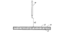
一般に、スタイラス10によって電子装置12から受信された信号の強度、または電子装置12によってスタイラス10から受信された信号の強度は、スタイラス10と電子装置12とが互いに近接しているときのほうが大きく、スタイラス10と電子装置12とが互いに遠ざかっているときのほうが小さい。例えば、図2Aは、電子装置12のスタイラスセンサ14から第1の高さまたは距離d1にあるスタイラス10、より具体的にはスタイラスの先端にある電極27の例を示す、一態様に係る図である。図2Bは、スタイラス10がスタイラスセンサ14から第1の距離d1にあるときにスタイラスセンサ14の検知アンテナによってスタイラス10から受信された信号31の信号プロファイルの例を示す、一態様に係る図である。図2Bのx軸に沿って11個の検知アンテナを示し、検知アンテナによって受信された信号31の強度を図2Bのy軸に沿って示す。受信された信号の強度は、電圧、電流、テスラ、及びボルト毎メートルなどの、信号強度を示す任意の種類の単位によるものであり得る。図3Aは、電子装置12のスタイラスセンサ14から第2の高さまたは距離d2にあるスタイラス10、より具体的にはスタイラスの先端にある電極27の例を示す、一態様に係る図である。第2の距離d2は、第1の距離d1より大きい。例えば、第1の距離d1は0〜10ミリメートルの範囲内にあり得るとともに、第2の距離d2は15〜25ミリメートルの範囲内にあり得る。図3Bは、スタイラスがスタイラスセンサ14から第2の距離d2にあるときにスタイラスセンサ14の検知アンテナによってスタイラス10から受信された信号33の信号プロファイルの例を示す、一態様に係る図である。図2Bと同様に、図3Bのx軸に沿って11個の検知アンテナを示し、検知アンテナによって受信された信号33の強度を図3Bのy軸に沿って示す。
In general, the strength of the signal received from the
図2Bと図3Bとを比較することによって、検知アンテナによって受信された信号の強度は、スタイラス10がスタイラスセンサ14に接近すると増加することがわかる。例えば、番号6の検知アンテナによって検知された信号31の強度は、スタイラス10がスタイラスセンサ14から第1の距離d1にあるときに0.18という値を有し、番号6の検知アンテナによって検知された信号33の強度は、スタイラス10がスタイラスセンサ14から第1の距離d1より大きい第2の距離d2にあるときに0.02未満の値を有する。
By comparing FIGS. 2B and 3B, it can be seen that the strength of the signal received by the detection antenna increases as the
したがって、スタイラスとスタイラスセンサとの間で送信される信号の強度を、スタイラス10とスタイラスセンサ14との間の距離の代わりとして、または指標として用い得る。
Therefore, the strength of the signal transmitted between the stylus and the stylus sensor can be used as a substitute for or as an indicator of the distance between the
一態様において、スタイラス10から送信される信号の強度は、スタイラス10と電子装置12との間の距離または高さに基づいて動的に調整される。スタイラス10と電子装置12との間で送信される信号の強度は、距離または高さの指標として用いられる。より詳細に後述するように、スタイラス10から送信される信号の強度を調整することによって、スタイラス10が検出され得る距離を増加させ、スタイラスセンサ14で検出される信号の過飽和を防止し、スタイラス10の消費電力を節約する。
In one embodiment, the strength of the signal transmitted from the
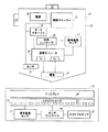
図4は、一態様に係る、スタイラス10によって送信される信号の信号強度を調整する処理の例を示すフロー図である。
FIG. 4 is a flow chart showing an example of a process for adjusting the signal strength of the signal transmitted by the
ステップ34において、本処理が開始される。ステップS36において、スタイラス10と電子装置12との間で現在送信されている信号(すなわち、スタイラス10から電子装置12に送信される信号、または電子装置12からスタイラス10に送信される信号)の強度を計測する。前述したように、信号強度は、スタイラス10が電子装置12からどの程度離れているかを示す。したがって、現在送信されている信号の計測された信号強度は、スタイラスセンサ14に対するスタイラス10の現在位置を示す。当該信号は、スタイラス10と電子装置12との間で送信される任意の信号からなり得る。例えば、前述したように、当該信号は、スタイラス機能情報、動作データ、またはコマンドを送信するデータ信号からなり得る。前述したように、信号の強度は、電圧、電流、テスラ、及びボルト毎メートルなどの、信号強度を示す任意の種類の計測値からなり得る。
In
一態様において、信号の強度はスタイラス10によって計測される。例えば、コマンドなどの信号は、スタイラス10の通信モジュール30によって電子装置12から受信され、受信された信号の強度は信号強度センサ32によって計測される。
In one embodiment, the signal strength is measured by the
他の態様において、信号の強度は電子装置12によって計測される。例えば、ビーコン信号またはデータ信号などの信号は、スタイラスセンサ14の検知アンテナ15によってスタイラス10から受信され、受信された信号の強度は信号強度センサ17によって計測される。より詳細に後述するように、本態様において、電子装置12は、計測された信号強度に基づくコマンドと信号強度を示すデータとのいずれかを、スタイラス10に送信し得る。
In another embodiment, the signal strength is measured by the
他の態様において、信号の強度は、スタイラス10によって計測された強度と電子装置12によって計測された強度との組合せに基づいて計測される。
In another embodiment, the signal strength is measured based on the combination of the strength measured by the
ステップ38において、ステップ36において計測された信号の強度が第1の閾値40以下であるか否か(すなわち、スタイラス10及び電子装置12が互いに遠方にあるか否か)を判定する。例えば、図2B及び図3Bにおいて、第1の閾値40は0.1という値を有する。一態様において、第1の閾値40は、スタイラス10と電子装置12との間の特定の距離または高さに応じて設定される。つまり、第1の閾値40は、20ミリメートルといった、スタイラス10と電子装置12との間の特定の距離に相当する値に設定される。他の態様において、第1の閾値40は、スタイラスセンサ14の検知機能に基づいて設定される。例えば、第1の閾値40は、第2の閾値50未満の信号強度がスタイラスセンサ14によって適正に検出されず、かつ第2の閾値50を超過する信号強度がスタイラスセンサ14によって適正に検出されるように設定され得る。
In
一態様において、前述したように、信号の強度はスタイラス10によって計測される。本態様において、ステップ38の判定はスタイラス10によって実行される。
In one embodiment, as described above, the signal strength is measured by the
他の態様において、前述したように、信号の強度は電子装置12によって計測される。本態様において、ステップ38の判定は電子装置12によって実行される。
In another embodiment, as described above, the signal strength is measured by the
ステップ36において計測した信号の強度が第1の閾値40以上である場合は、スタイラス10が電子装置12に近接しているとみなす。例えば、図2Bを参照すると、スタイラス10がスタイラスセンサ14から第1の距離d1にあるときは、信号31の強度は第1の閾値40より大きい。処理は、次いでステップ42に移行する。
When the intensity of the signal measured in
ステップ36において計測した信号の強度が第1の閾値40未満である場合は、スタイラス10が電子装置12から遠方にあるとみなす。例えば、図3Bを参照すると、スタイラス10がスタイラスセンサ14から第2の距離d2にあるときは、信号33の強度は第1の閾値40より小さい。処理は、次いでステップ44に移行する。
If the strength of the signal measured in
ステップ44において、スタイラス10によって送信される信号の強度を増加させ、または増幅する。信号の強度は利得コントローラ29によって増加される。信号の強度を増加させ、または増幅することにより、スタイラス10は電子装置12によってより離れた距離から検出され得る。一態様において、電子装置12がスタイラス10を少なくとも20ミリメートル離れたところから検出し得るように、信号の強度を増加させる。または他の態様においては、送信される信号の信号強度の増加は、増加された信号強度が電子装置12の受信回路(例えば、検知アンテナ15)を飽和させないように選択される。
In
一態様において、前述したように、信号の強度はスタイラス10によって計測される。本態様において、増幅された信号は、スタイラス10によって現在送信されている信号とスタイラス10によって送信される後続の信号とのいずれかからなる。さらに、スタイラス10によって送信される信号の強度の増加は、スタイラス10自体によって開始及び実行される。
In one embodiment, as described above, the signal strength is measured by the
他の態様において、前述したように、信号の強度は電子装置12によって計測される。本態様において、増幅された信号は、ステップ36において計測された信号とスタイラス10によって送信される後続の信号とのいずれかからなる。さらに、スタイラス10によって送信される信号の強度の増加は、電子装置12によって開始及び実行される。特に、一態様において、電子装置12は、スタイラス10に信号の強度を増加させるように指示するコマンドをスタイラス10に送信する。他の態様において、電子装置12は、ステップ36において計測した信号の強度を示すデータをスタイラス10に送信し、スタイラス10はこれに従って信号の強度を変化(増加)させる。当該コマンド及び当該データはセンサコントローラ16を介して送信される。態様によっては、当該コマンド及び当該データを、電子装置12に対するスタイラス10の高さを示す高さ信号と総称する。信号の強度を増加または減少させるコマンドが、判定したスタイラス10の高さはそれぞれ高い、低いことを示すという点で、コマンドはスタイラス10の高さを示す。計測した信号の強度が低下または増加したことを示すデータが、同様に、スタイラス10はそれぞれ高い、低いことを示すという点で、データはスタイラス10の高さを示す。
In another embodiment, as described above, the signal strength is measured by the
一態様において、信号の強度を離散的な複数のステップで増加させる。他の態様において、信号の強度を連続的に増加させる。信号の強度を連続的に増加させる場合に、受信された信号強度と送信された信号強度との間の関係は、実装に応じて、区分的線形、線形、幾何的、または、レシーバとトランスミッタとの間の他の伝達関数からなり得る。 In one embodiment, the signal strength is increased in multiple discrete steps. In other embodiments, the signal strength is continuously increased. When increasing the signal strength continuously, the relationship between the received signal strength and the transmitted signal strength is piecewise linear, linear, geometric, or with the receiver and transmitter, depending on the implementation. It can consist of other transfer functions between.
一態様において、自動利得制御(AGC)の形態を用いて、受信された信号に基づき、送信される信号強度を変化させる。例えば、AGCによる利得信号を、送信信号強度制御に用い得る。このことは特に、タッチ走査信号を再送信するスタイラスにとって有用である。本態様において、スタイラス10は信号強度を制御する。
In one embodiment, the form of automatic gain control (AGC) is used to vary the transmitted signal strength based on the received signal. For example, the gain signal by AGC can be used for transmission signal strength control. This is especially useful for styli that retransmit touch scan signals. In this embodiment, the
ステップ46において、スタイラス10は増幅した信号を送信する。増幅された信号は、通信モジュール30によって送信回路(TX)及び電極27を介して送信される。処理は、次いでステップ48に移行する。
In
ステップ48において、電子装置12は、スタイラス10からの送信信号を検出する。当該信号は、スタイラスセンサ14の検知アンテナ15によって検知される。当該信号が電子装置12によって検出されると、電子装置12、より具体的にはセンサコントローラ16またはホストプロセッサ18は、応答において種々の動作を実行する。一態様において、電子装置12は、スタイラス10または電子装置12を保持する手などの意図しないタッチが誤検出されないように、増幅された信号を除いて、指タッチなどの、スタイラスセンサ14による他の種類の検出を無視する。処理は、次いでステップ36に戻り、スタイラス10と電子装置との間で現在送信されている信号の強度を計測する。
In
ステップ38に戻り、信号の強度が第1の閾値40以上である場合は、処理はステップ42に移行する。ステップ42において、ステップ36において計測した信号の強度が第2の閾値50以上であって(すなわち、スタイラス10及び電子装置12が互いに近接しているか)、かつ許容レベル内にあるか否かを判定する。例えば、図2B及び図3Bにおいて、第2の閾値50は0.2という値を有する。一態様において、第2の閾値50は、スタイラス10と電子装置12との間の距離に応じて設定される。つまり、第2の閾値50は、5ミリメートルといった、スタイラス10と電子装置12との間の特定の距離に相当する値に設定される。他の態様において、第2の閾値50は、スタイラス10によって送信された信号によって過負荷となる、または飽和することに起因した、スタイラスセンサ14による不適切な位置計測値を回避するように設定される。例えば、第2の閾値50は、第2の閾値50未満の信号強度がスタイラスセンサ14を過負荷としない、または飽和させず、かつ第2の閾値50を超過する信号強度がスタイラスセンサ14を過負荷とし、または飽和させ得るように設定され得る。他の態様において、第2の閾値50は、スタイラス10の消費電力を節約し、過度なバッテリ消費を回避するように設定される。例えば、第2の閾値50は、第2の閾値50未満の信号強度が電源20の消費電力を過度に消費せずに、かつ第2の閾値50を超過する信号強度が電源20の消費電力を過度に消費し得るように設定され得る。
Returning to step 38, if the signal strength is equal to or higher than the
一態様において、前述したように、信号の強度はスタイラス10によって計測される。本態様において、ステップ36の判定はスタイラス10によって実行される。
In one embodiment, as described above, the signal strength is measured by the
他の態様において、前述したように、信号の強度は電子装置12によって計測される。本態様において、ステップ36の判定は電子装置12によって実行される。
In another embodiment, as described above, the signal strength is measured by the
ステップ36において計測した信号の強度が第2の閾値50以下である場合は、スタイラス10と電子装置12とは互いに近接しておらず、かつスタイラス10によって送信される信号の現在の強度は許容レベル内にあるとみなす。したがって、対処せずに、スタイラス10によって送信される信号の現在の強度を維持する。処理は、次いでステップ36に戻り、スタイラス10と電子装置12との間で送信される他のまたは後続の信号の強度を計測する。
When the intensity of the signal measured in
ステップ36において計測した信号の強度が第2の閾値50より大きい場合は、スタイラス10と電子装置12とは互いに近接しており、かつスタイラス10によって現在送信されている信号の強度は許容レベル内にないとみなす。処理は、次いでステップ52に移行する。
When the strength of the signal measured in
ステップ52において、スタイラス10によって送信される信号の強度を低下させて、適切な強度レベルに設定する。信号の強度は利得コントローラ29によって低下される。スタイラス10によって送信される信号の強度を低下させることによって、スタイラス10によって送信される信号により過負荷となる、または飽和することに起因したスタイラスセンサ14による不適切な位置計測値を防止し得るとともに、消費電力を節約し得る。
In
一態様において、前述したように、信号の強度はスタイラス10によって計測される。本態様において、減衰される信号は、スタイラス10によって現在送信されている信号とスタイラス10によって送信される後続の信号とのいずれかからなる。さらに、スタイラス10によって送信される信号の強度の低下は、スタイラス10自体によって開始または実行される。
In one embodiment, as described above, the signal strength is measured by the
他の態様において、前述したように、信号の強度は電子装置12によって計測される。本態様において、減衰される信号は、ステップ36において計測した信号とスタイラス10によって送信される後続の信号とのいずれかからなる。さらに、スタイラス10によって送信される信号の強度の減少は、電子装置12によって開始または実行される。特に、一態様において、電子装置12は、スタイラス10に信号の強度を減少させるように指示するコマンドをスタイラス10に送信する。他の態様において、電子装置12は、ステップ36において計測した信号の強度を示すデータをスタイラス10に送信し、スタイラス10はこれに従って信号の強度を減少させる。当該コマンド及び当該データはセンサコントローラ16を介して送信される。
In another embodiment, as described above, the signal strength is measured by the
一態様において、信号の強度を離散的な複数のステップで減少させる。他の態様において、信号の強度を連続的に減少させる。信号の強度を連続的に増加させる場合に、受信された信号強度と送信された信号強度との間の関係は、実装に応じて、区分的線形、線形、幾何的、またはレシーバとトランスミッタとの間の他の伝達関数から規定され得る。 In one embodiment, the signal strength is reduced in multiple discrete steps. In other embodiments, the signal strength is continuously reduced. When increasing the signal strength continuously, the relationship between the received signal strength and the transmitted signal strength is piecewise linear, linear, geometric, or between the receiver and the transmitter, depending on the implementation. It can be defined by other transfer functions between.
一態様において、第2の閾値50は第1の閾値40より大きい。第1の閾値40及び第2の閾値50に2つの異なる値を用いることによって、スタイラス10によって送信される信号の強度の不必要な増減を回避し得る。例えば、ステップ38及びステップ42に単一の閾値を用いる場合に、当該単一の閾値の上下に変動する信号は、ステップ42において減少される強度とステップ44において増加される強度との間で振動する強度を有するものとなる。ステップ38及びステップ42に対して2つの個別の閾値を用いることによって、信号強度制御にヒステリシスを設定することでこのような信号の増加と減少との交番を緩和または回避することが可能である。
In one embodiment, the
ステップ54において、スタイラス10は減衰させた信号を送信する。増幅された信号は、通信モジュール30によって送信回路(TX)及び電極27を介して送信される。処理は、次いでステップ48に移行する。上述したように、ステップ48において、電子装置12はスタイラス10からの送信信号を検出する。なお、電極27は、例えば、スタイラス10の芯体に配設された第1の電極と、この第1の電極を囲むように配設された、第1の電極とは電気的に分離された第2の電極から構成されており、第1の電極が送信回路(TX)に接続され、第2の電極が受信回路(RX)に接続されている。または、第1の電極が受信回路(RX)に接続され、第2の電極が送信回路(TX)に接続される。
In
1つまたは複数の態様に従って、スタイラス10によって送信される信号の信号強度を調整するシステム及び処理は、より離れた距離におけるスタイラス10の検出を向上させ、スタイラスセンサ14の過飽和を防止し、またスタイラス10の消費電力を節約する。スタイラスが電子装置12によって検出され得る距離を増加させることは、スタイラス及び指タッチを検知することが可能であるスタイラスセンサにとって特に有益である。スタイラスセンサの表面の上方においてスタイラスを十分に検出することによって、電子装置は、スタイラスを用いるユーザと自身の指を用いるユーザとを迅速に区別して相応に応答し得る。例えば、ユーザがスタイラスを用いていると判定すると、ユーザによる指タッチまたはハンドタッチを無視し得る。したがって、スタイラスまたは電子装置を保持しているユーザの手などの意図しないタッチを無視し得る。
Systems and processes that adjust the signal strength of the signal transmitted by the
上述した種々の態様を組み合わせて他の態様を提供することが可能である。これらの、または他の変更を、上記の詳細な説明に照らして当該態様に施し得る。一般に、以下の請求項において、用いられる用語が、請求項を明細書及び請求項において開示された特定の態様に限定すると解釈すべきではなく、すべての可能な態様を、このような請求項が当てはまる等価物の全範囲とともに含むと解釈すべきである。したがって、請求項は本開示によって限定されない。 It is possible to combine the various embodiments described above to provide other embodiments. These or other modifications may be made to such embodiments in the light of the detailed description above. In general, the terms used in the following claims should not be construed as limiting the claims to the specific embodiments disclosed in the specification and claims, but all possible embodiments are such. It should be interpreted as including with the full range of applicable equivalents. Therefore, the claims are not limited by this disclosure.
Claims (14)
筐体の先端部に配設された電極と、
前記電極を介して前記センサとの間で双方向通信を行う通信回路と、
前記電極からの信号送信のための信号発生器と、
信号強度コントローラと、
を備えており、
前記信号強度コントローラは、
前記通信回路を介して前記センサの表面と前記アクティブスタイラスとの間で通信される信号に基づいて、前記電極から送信される信号の強度を検知し、
前記電極から送信される信号の強度が、予め定められている第1の閾値以下であるときには、前記電極から送信される信号の強度を増加させるように制御し、
前記電極から送信される信号の強度が、予め定められている前記第1の閾値よりも大きいときには、前記第1の閾値よりも大きい第2の閾値以上であるか否かを判別し、前記第2の閾値以上であるときには、前記電極から送信される信号の強度を減少させるように制御し、
前記電極から送信される信号の強度が、予め定められている前記第1の閾値と前記第2の閾値との間の値であるときには、前記電極から送信される信号の強度を維持するように制御する
ことを特徴とするアクティブスタイラス。 An active stylus used with a sensor having a matrix of sensor conductors extending in different first and second directions.
Electrodes arranged at the tip of the housing and
A communication circuit that performs bidirectional communication with the sensor via the electrodes,
A signal generator for transmitting signals from the electrodes and
Signal strength controller and
Equipped with
The signal strength controller is
Based on the signal communicated between the surface of the sensor and the active stylus via the communication circuit, the intensity of the signal transmitted from the electrode is detected.
When the intensity of the signal transmitted from the electrode is equal to or less than a predetermined first threshold value, the intensity of the signal transmitted from the electrode is controlled to be increased.
When the intensity of the signal transmitted from the electrode is higher than the predetermined first threshold value, it is determined whether or not the strength is equal to or higher than the second threshold value larger than the first threshold value, and the first threshold value is determined. When it is equal to or higher than the threshold value of 2, it is controlled so as to reduce the intensity of the signal transmitted from the electrode.
When the intensity of the signal transmitted from the electrode is a value between the predetermined first threshold value and the second threshold value, the intensity of the signal transmitted from the electrode is maintained. An active stylus characterized by control.
ことを特徴とする請求項1に記載のアクティブスタイラス。 It is characterized by comprising means for measuring the intensity of the signal transmitted from the electrode based on the signal corresponding to the distance between the surface of the sensor and the active stylus acquired through the communication circuit. The active stylus according to claim 1.
ことを特徴とする請求項1に記載のアクティブスタイラス。 Before SL signal strength controller, acquired from the sensor through the communication circuit, based on a command signal corresponding to the distance between the active stylus and the surface of the sensor, the signal transmitted from the previous SL electrode The active stylus according to claim 1, wherein the active stylus is characterized by detecting the intensity.
ことを特徴とする請求項1に記載のアクティブスタイラス。The active stylus according to claim 1.
ことを特徴とする請求項1に記載のアクティブスタイラス。 The signal intensity controller is active stylus according to claim 1, characterized in that the increase or the decrease of the strength of the signal transmitted that controls stepwise before Symbol electrode.
ことを特徴とする請求項1に記載のアクティブスタイラス。 The signal intensity controller is active stylus according to claim 1, characterized in that you continuously control the increase or the decrease in the intensity of the signal transmitted from the previous SL electrode.
前記センサと前記アクティブスタイラスとの間は双方向通信が行われ、
前記センサの表面と前記アクティブスタイラスとの間で通信される信号に基づいて、前記アクティブスタイラスの電極から送信される信号の強度を検知し、
前記電極から送信される信号の強度が、予め定められている第1の閾値以下であるときには、前記電極から送信される信号の強度を増加させるように制御し、
前記電極から送信される信号の強度が、予め定められている前記第1の閾値よりも大きいときには、前記第1の閾値よりも大きい第2の閾値以上であるか否かを判別し、前記第2の閾値以上であるときには、前記電極から送信される信号の強度を減少させるように制御し、
前記電極から送信される信号の強度が、予め定められている前記第1の閾値と前記第2の閾値との間の値であるときには、前記電極から送信される信号の強度を維持するように制御する
ことを特徴とするアクティブスタイラスの送信信号強度の制御方法。 A method of controlling the transmitted signal strength of an active stylus used with a sensor having a matrix-like sensor wiring extending in different first and second directions.
Two-way communication is performed between the sensor and the active stylus.
Based on the signal communicated between the surface of the sensor and the active stylus, the intensity of the signal transmitted from the electrode of the active stylus is detected.
When the intensity of the signal transmitted from the electrode is equal to or less than a predetermined first threshold value, the intensity of the signal transmitted from the electrode is controlled to be increased.
When the intensity of the signal transmitted from the electrode is higher than the predetermined first threshold value, it is determined whether or not the strength is equal to or higher than the second threshold value larger than the first threshold value, and the first threshold value is determined. When it is equal to or higher than the threshold value of 2, it is controlled so as to reduce the intensity of the signal transmitted from the electrode.
When the intensity of the signal transmitted from the electrode is a value between the predetermined first threshold value and the second threshold value, the intensity of the signal transmitted from the electrode is maintained. A method of controlling the transmission signal strength of an active stylus, which comprises controlling.
ことを特徴とする請求項10に記載のアクティブスタイラスの送信信号強度の制御方法。 Command signal is transmitted from the sensor, according to claim 10, characterized in that to detect the intensity of the signal transmitted from the active stylus housing of arranged at the distal end portion has been electrodes on the basis of said command signal A method for controlling the transmission signal strength of the active stylus described in.
ことを特徴とする請求項11に記載のアクティブスタイラスの送信信号強度の制御方法。 The method for controlling the transmission signal strength of the active stylus according to claim 11 , wherein the transmission of the command signal from the sensor to the active stylus is performed by electrostatic communication with the sensor.
ことを特徴とする請求項11に記載のアクティブスタイラスの送信信号強度の制御方法。 The method for controlling the transmission signal strength of the active stylus according to claim 11 , wherein the transmission of the command signal from the sensor to the active stylus is performed by RF communication.
ことを特徴とする請求項10に記載のアクティブスタイラスの送信信号強度の制御方法。The method for controlling the transmission signal strength of the active stylus according to claim 10.
Applications Claiming Priority (2)
| Application Number | Priority Date | Filing Date | Title |
|---|---|---|---|
| US15/345,943 | 2016-11-08 | ||
| US15/345,943 US10073548B2 (en) | 2016-11-08 | 2016-11-08 | Stylus having variable transmit signal strength, and sensor for detecting such stylus |
Publications (3)
| Publication Number | Publication Date |
|---|---|
| JP2018077826A JP2018077826A (en) | 2018-05-17 |
| JP2018077826A5 JP2018077826A5 (en) | 2020-09-10 |
| JP6971083B2 true JP6971083B2 (en) | 2021-11-24 |
Family
ID=60268264
Family Applications (1)
| Application Number | Title | Priority Date | Filing Date |
|---|---|---|---|
| JP2017156317A Active JP6971083B2 (en) | 2016-11-08 | 2017-08-14 | A stylus with variable transmit signal strength and a sensor to detect such a stylus |
Country Status (6)
| Country | Link |
|---|---|
| US (1) | US10073548B2 (en) |
| EP (1) | EP3318962B1 (en) |
| JP (1) | JP6971083B2 (en) |
| KR (1) | KR102384569B1 (en) |
| CN (1) | CN108062173B (en) |
| TW (1) | TWI749023B (en) |
Families Citing this family (7)
| Publication number | Priority date | Publication date | Assignee | Title |
|---|---|---|---|---|
| CN111373357B (en) | 2017-11-29 | 2023-09-22 | 株式会社和冠 | Communication method executed between active pen and sensor controller and active pen |
| WO2019220803A1 (en) * | 2018-05-18 | 2019-11-21 | 株式会社ワコム | Position indication device and information processing device |
| WO2020047777A1 (en) * | 2018-09-05 | 2020-03-12 | 深圳市汇顶科技股份有限公司 | Touch sensing method, touch chip, electronic device, and touch system |
| US10884522B1 (en) * | 2019-06-19 | 2021-01-05 | Microsoft Technology Licensing, Llc | Adaptive hover operation of touch instruments |
| KR20210012838A (en) | 2019-07-26 | 2021-02-03 | 삼성전자주식회사 | Electronic device and method for controlling digitizer panel of electronic device based on status of electronic pen thereof |
| KR20220014370A (en) * | 2020-07-23 | 2022-02-07 | 삼성디스플레이 주식회사 | Input device and the interface device including the same |
| US11775084B2 (en) * | 2021-04-20 | 2023-10-03 | Microsoft Technology Licensing, Llc | Stylus haptic component arming and power consumption |
Family Cites Families (14)
| Publication number | Priority date | Publication date | Assignee | Title |
|---|---|---|---|---|
| US7298367B2 (en) * | 2003-11-25 | 2007-11-20 | 3M Innovative Properties Company | Light emitting stylus and user input device using same |
| JP2010067117A (en) * | 2008-09-12 | 2010-03-25 | Mitsubishi Electric Corp | Touch panel device |
| US9195351B1 (en) * | 2011-09-28 | 2015-11-24 | Amazon Technologies, Inc. | Capacitive stylus |
| US9606641B2 (en) * | 2015-03-09 | 2017-03-28 | Atmel Corporation | Adaptive transmit voltage in active stylus |
| KR20140017255A (en) * | 2012-07-31 | 2014-02-11 | 삼성전자주식회사 | Electric pen input recognition apparatus and method using c-type tsp |
| US9841862B2 (en) * | 2012-10-16 | 2017-12-12 | Atmel Corporation | Stylus position system |
| TWI559178B (en) * | 2014-05-13 | 2016-11-21 | 禾瑞亞科技股份有限公司 | Touch sensitive processing apparatus and detecting method thereof, and touch sensitive system |
| TWI628560B (en) * | 2014-05-27 | 2018-07-01 | 禾瑞亞科技股份有限公司 | Touch processor |
| US9632597B2 (en) | 2014-06-12 | 2017-04-25 | Amazon Technologies, Inc. | Configurable active stylus devices |
| CN115756154A (en) * | 2014-09-02 | 2023-03-07 | 苹果公司 | Semantic framework for variable haptic output |
| US9575573B2 (en) * | 2014-12-18 | 2017-02-21 | Apple Inc. | Stylus with touch sensor |
| JP6487694B2 (en) * | 2014-12-26 | 2019-03-20 | 株式会社ワコム | Position indicator and signal processing device |
| JP6544791B2 (en) * | 2015-02-20 | 2019-07-17 | 株式会社ワコム | Position indicator, signal processing circuit, signal supply control method and signal processing method |
| US9841828B2 (en) * | 2016-04-20 | 2017-12-12 | Microsoft Technology Licensing, Llc | Pressure sensitive stylus |
-
2016
- 2016-11-08 US US15/345,943 patent/US10073548B2/en active Active
-
2017
- 2017-06-28 TW TW106121636A patent/TWI749023B/en active
- 2017-07-27 CN CN201710622929.1A patent/CN108062173B/en active Active
- 2017-08-14 JP JP2017156317A patent/JP6971083B2/en active Active
- 2017-10-17 KR KR1020170134880A patent/KR102384569B1/en active IP Right Grant
- 2017-11-06 EP EP17200093.7A patent/EP3318962B1/en active Active
Also Published As
| Publication number | Publication date |
|---|---|
| EP3318962A1 (en) | 2018-05-09 |
| JP2018077826A (en) | 2018-05-17 |
| KR20180051368A (en) | 2018-05-16 |
| TWI749023B (en) | 2021-12-11 |
| EP3318962B1 (en) | 2021-06-23 |
| US20180129305A1 (en) | 2018-05-10 |
| KR102384569B1 (en) | 2022-04-08 |
| CN108062173A (en) | 2018-05-22 |
| TW201818202A (en) | 2018-05-16 |
| CN108062173B (en) | 2023-04-11 |
| US10073548B2 (en) | 2018-09-11 |
Similar Documents
| Publication | Publication Date | Title |
|---|---|---|
| JP6971083B2 (en) | A stylus with variable transmit signal strength and a sensor to detect such a stylus | |
| JP7021889B2 (en) | Stylus and tilt detection method for stylus | |
| US9152236B2 (en) | Apparatus for remotely controlling another apparatus and having self-orientating capability | |
| EP3825814A1 (en) | Electronic device and communication method thereof | |
| US11841221B2 (en) | Mobile device and method for sensor data based antenna selection | |
| CN107153481B (en) | Touch processing method, device and system for correcting pressure value of touch pen | |
| CN110139018B (en) | Camera control module, camera movement control method and terminal | |
| US9464920B2 (en) | Sensing apparatus for measuring position of touch object by electromagnetic induction and method for controlling the same | |
| US20180129307A1 (en) | Touch control system and method for determining tilt state of stylus device | |
| CN105204764B (en) | Handheld terminal with suspension screen, display device and remote control method | |
| US20180314364A1 (en) | Stylus and electronic system thereof | |
| KR102551209B1 (en) | Electronic device for controlling an output of an antenna using auto phase control of communication module and method for the same | |
| TW202234840A (en) | Electronic device | |
| JPWO2020158088A1 (en) | Drawing system | |
| CN108592861B (en) | Direction sensor optimization method and device, storage medium and terminal equipment | |
| US20240062575A1 (en) | Electronic device method for adjusting configuration data of fingerprint sensor | |
| KR20240021072A (en) | Stylus pen with adjustable pen pressure, electronic device using the same as an input device, and operating method thereof | |
| KR20230067428A (en) | Electronic device, method, non-transitory computer readable storage medium for adjusting lumminance of display based on angle formed with earbuds | |
| KR20220013215A (en) | Electronic device sensing touch input and method thereof | |
| CN116057499A (en) | Active pen |
Legal Events
| Date | Code | Title | Description |
|---|---|---|---|
| A521 | Request for written amendment filed |
Free format text: JAPANESE INTERMEDIATE CODE: A523 Effective date: 20200730 |
|
| A621 | Written request for application examination |
Free format text: JAPANESE INTERMEDIATE CODE: A621 Effective date: 20200730 |
|
| A977 | Report on retrieval |
Free format text: JAPANESE INTERMEDIATE CODE: A971007 Effective date: 20210531 |
|
| A131 | Notification of reasons for refusal |
Free format text: JAPANESE INTERMEDIATE CODE: A131 Effective date: 20210623 |
|
| A521 | Request for written amendment filed |
Free format text: JAPANESE INTERMEDIATE CODE: A523 Effective date: 20210630 |
|
| TRDD | Decision of grant or rejection written | ||
| A01 | Written decision to grant a patent or to grant a registration (utility model) |
Free format text: JAPANESE INTERMEDIATE CODE: A01 Effective date: 20211006 |
|
| A61 | First payment of annual fees (during grant procedure) |
Free format text: JAPANESE INTERMEDIATE CODE: A61 Effective date: 20211101 |
|
| R150 | Certificate of patent or registration of utility model |
Ref document number: 6971083 Country of ref document: JP Free format text: JAPANESE INTERMEDIATE CODE: R150 |