JP6968645B2 - Image processing equipment, image processing methods and programs - Google Patents
Image processing equipment, image processing methods and programs Download PDFInfo
- Publication number
- JP6968645B2 JP6968645B2 JP2017193026A JP2017193026A JP6968645B2 JP 6968645 B2 JP6968645 B2 JP 6968645B2 JP 2017193026 A JP2017193026 A JP 2017193026A JP 2017193026 A JP2017193026 A JP 2017193026A JP 6968645 B2 JP6968645 B2 JP 6968645B2
- Authority
- JP
- Japan
- Prior art keywords
- cluster
- image
- image processing
- movement vector
- processing apparatus
- Prior art date
- Legal status (The legal status is an assumption and is not a legal conclusion. Google has not performed a legal analysis and makes no representation as to the accuracy of the status listed.)
- Active
Links
Images


Classifications
-
- G—PHYSICS
- G06—COMPUTING; CALCULATING OR COUNTING
- G06T—IMAGE DATA PROCESSING OR GENERATION, IN GENERAL
- G06T11/00—2D [Two Dimensional] image generation
- G06T11/20—Drawing from basic elements, e.g. lines or circles
- G06T11/206—Drawing of charts or graphs
-
- G—PHYSICS
- G06—COMPUTING; CALCULATING OR COUNTING
- G06F—ELECTRIC DIGITAL DATA PROCESSING
- G06F18/00—Pattern recognition
- G06F18/20—Analysing
- G06F18/23—Clustering techniques
-
- G—PHYSICS
- G06—COMPUTING; CALCULATING OR COUNTING
- G06F—ELECTRIC DIGITAL DATA PROCESSING
- G06F18/00—Pattern recognition
- G06F18/20—Analysing
- G06F18/24—Classification techniques
- G06F18/243—Classification techniques relating to the number of classes
- G06F18/2433—Single-class perspective, e.g. one-against-all classification; Novelty detection; Outlier detection
-
- G—PHYSICS
- G06—COMPUTING; CALCULATING OR COUNTING
- G06T—IMAGE DATA PROCESSING OR GENERATION, IN GENERAL
- G06T11/00—2D [Two Dimensional] image generation
- G06T11/60—Editing figures and text; Combining figures or text
-
- G—PHYSICS
- G06—COMPUTING; CALCULATING OR COUNTING
- G06T—IMAGE DATA PROCESSING OR GENERATION, IN GENERAL
- G06T7/00—Image analysis
- G06T7/20—Analysis of motion
- G06T7/246—Analysis of motion using feature-based methods, e.g. the tracking of corners or segments
- G06T7/248—Analysis of motion using feature-based methods, e.g. the tracking of corners or segments involving reference images or patches
-
- G—PHYSICS
- G06—COMPUTING; CALCULATING OR COUNTING
- G06V—IMAGE OR VIDEO RECOGNITION OR UNDERSTANDING
- G06V10/00—Arrangements for image or video recognition or understanding
- G06V10/70—Arrangements for image or video recognition or understanding using pattern recognition or machine learning
- G06V10/762—Arrangements for image or video recognition or understanding using pattern recognition or machine learning using clustering, e.g. of similar faces in social networks
-
- G—PHYSICS
- G06—COMPUTING; CALCULATING OR COUNTING
- G06V—IMAGE OR VIDEO RECOGNITION OR UNDERSTANDING
- G06V10/00—Arrangements for image or video recognition or understanding
- G06V10/70—Arrangements for image or video recognition or understanding using pattern recognition or machine learning
- G06V10/764—Arrangements for image or video recognition or understanding using pattern recognition or machine learning using classification, e.g. of video objects
-
- G—PHYSICS
- G06—COMPUTING; CALCULATING OR COUNTING
- G06V—IMAGE OR VIDEO RECOGNITION OR UNDERSTANDING
- G06V20/00—Scenes; Scene-specific elements
- G06V20/50—Context or environment of the image
- G06V20/52—Surveillance or monitoring of activities, e.g. for recognising suspicious objects
- G06V20/53—Recognition of crowd images, e.g. recognition of crowd congestion
-
- G—PHYSICS
- G06—COMPUTING; CALCULATING OR COUNTING
- G06T—IMAGE DATA PROCESSING OR GENERATION, IN GENERAL
- G06T2207/00—Indexing scheme for image analysis or image enhancement
- G06T2207/20—Special algorithmic details
- G06T2207/20084—Artificial neural networks [ANN]
-
- G—PHYSICS
- G06—COMPUTING; CALCULATING OR COUNTING
- G06T—IMAGE DATA PROCESSING OR GENERATION, IN GENERAL
- G06T2207/00—Indexing scheme for image analysis or image enhancement
- G06T2207/30—Subject of image; Context of image processing
- G06T2207/30196—Human being; Person
-
- G—PHYSICS
- G06—COMPUTING; CALCULATING OR COUNTING
- G06T—IMAGE DATA PROCESSING OR GENERATION, IN GENERAL
- G06T2207/00—Indexing scheme for image analysis or image enhancement
- G06T2207/30—Subject of image; Context of image processing
- G06T2207/30232—Surveillance
Landscapes
- Engineering & Computer Science (AREA)
- Theoretical Computer Science (AREA)
- General Physics & Mathematics (AREA)
- Physics & Mathematics (AREA)
- Data Mining & Analysis (AREA)
- Computer Vision & Pattern Recognition (AREA)
- Artificial Intelligence (AREA)
- Evolutionary Computation (AREA)
- Multimedia (AREA)
- Databases & Information Systems (AREA)
- Bioinformatics & Cheminformatics (AREA)
- Medical Informatics (AREA)
- General Health & Medical Sciences (AREA)
- Health & Medical Sciences (AREA)
- Computing Systems (AREA)
- Life Sciences & Earth Sciences (AREA)
- Software Systems (AREA)
- Bioinformatics & Computational Biology (AREA)
- Evolutionary Biology (AREA)
- General Engineering & Computer Science (AREA)
- Image Analysis (AREA)
- Closed-Circuit Television Systems (AREA)
- Alarm Systems (AREA)
Description
本発明は、画像処理装置、画像処理方法及びプログラムに関する。 The present invention relates to an image processing apparatus, an image processing method and a program.
近年、撮像装置で所定の領域を撮影して、撮影した画像を解析することによって画像中の人流を解析するシステムが提案されている。人流の解析により、通常時の人流の向きと異なる向きに流れる人流の発生や、大勢の群衆の流れに逆らって移動する小規模な一団の発生等をいち早く検出することができる。このようなシステムの活用により、公共領域や大規模商業施設等における予期せぬ損害等の未然防止等の実現が期待されている。
特許文献1は、人物同士が接触するほど密集した群衆の人流を解析し、群衆内に異常な動きが発生したことを検知する技術を開示している。特許文献1の技術では、時系列画像を複数の時空間セグメントに分割し、時空間セグメントのそれぞれに対して動き特徴量を算出し、時空間セグメントごとに、正常セグメントか異常セグメントかの何れかに分類する。
In recent years, a system has been proposed in which a predetermined area is photographed by an image pickup apparatus and the photographed image is analyzed to analyze the flow of people in the image. By analyzing the flow of people, it is possible to quickly detect the occurrence of a flow of people flowing in a direction different from the direction of the normal flow of people, or the occurrence of a small group moving against the flow of a large crowd. Utilization of such a system is expected to realize prevention of unexpected damages in public spheres and large-scale commercial facilities.
しかしながら、時空間セグメントは、必ずしも群衆を構成する人ひとりひとりと一致するとは限らない。そのため、異常な人流を検出することはできるが、その人流を構成する人数が何人か等の情報を取得することができない問題があった。 However, the spatiotemporal segment does not always match each and every person who makes up the crowd. Therefore, although it is possible to detect an abnormal flow of people, there is a problem that it is not possible to obtain information such as the number of people constituting the flow of people.
本発明の画像処理装置は、画像の部分画像ごとに人物の動きを表す移動ベクトルを取得する取得手段と、前記取得手段により取得された移動ベクトルに基づいて、所定の条件を満たす前記人物の集合であるクラスタを生成する生成手段と、前記生成手段により生成されたクラスタのうち、前記部分画像における前記クラスタの発生確率が予め記憶された所定の値より小さいクラスタを出力する出力手段と、を有する。 The image processing apparatus of the present invention is a set of the person who satisfies a predetermined condition based on the acquisition means for acquiring a movement vector representing the movement of the person for each partial image of the image and the movement vector acquired by the acquisition means. It has a generation means for generating a cluster, and an output means for outputting a cluster generated by the generation means, in which the occurrence probability of the cluster in the partial image is smaller than a predetermined value stored in advance. ..
本発明によれば、異常な人流に関する情報をユーザに提示可能とすることができる。 According to the present invention, it is possible to present information on an abnormal flow of people to a user.
以下、本発明の実施形態について図面に基づいて説明する。 Hereinafter, embodiments of the present invention will be described with reference to the drawings.
<実施形態1>
図1は、画像処理装置100のハードウェア構成の一例を示す図である。
画像処理装置100は、ハードウェア構成として、CPU10、メモリ11、ネットワークI/F12、表示装置13、入力装置14を含む。CPU10は、画像処理装置100の全体の制御を司る。メモリ11は、CPU10が処理に利用するデータ、プログラム等を記憶する。入力装置14は、マウス、又はボタン等であり、ユーザの操作を画像処理装置100に入力する。表示装置13は、液晶表示装置等であり、CPU10による処理の結果等を表示する。ネットワークI/F12は、画像処理装置100をネットワークに接続するインタフェースである。CPU10がメモリ11に記憶されたプログラムに基づき処理を実行することにより、後述する図2の画像処理装置100の機能構成及び後述する図3のフローチャートの処理が実現される。
<
FIG. 1 is a diagram showing an example of a hardware configuration of an
The
図2は、画像処理装置100の機能構成の一例を示す図である。
画像処理装置100は、機能構成として、画像取得部201、移動ベクトル抽出部202、人流抽出部203、人流学習部204、異常人流判定部205、表示部206を含む。
画像取得部201は、人流解析の対象となる入力画像を取得する。
移動ベクトル抽出部202は、画像取得部201が取得した画像を、小画像に分割する。続いて、移動ベクトル抽出部202は、映像解析を行い、小画像ごとの移動ベクトルを取得する。ここで移動ベクトルとは、ある所定の微小時間(例えば1/5秒)において、群衆を構成する各個人の頭部がどの位置からどの位置まで動いたかを表す情報である。
人流抽出部203は、移動ベクトル抽出部202によって小画像ごとに推定された移動ベクトルを受け取る。続いて、人流抽出部203は、小画像ごとに移動ベクトルをクラスタリングし、移動ベクトルをいくつかのクラスタに分割することで、人流クラスタを得る。
人流学習部204は、人流抽出部203により得られた人流クラスタを、ある学習期間において収集する。そして、人流学習部204は、収集した人流クラスタから、人流クラスタの発生確率を統計的に得る。人流学習部204が人流クラスタの発生確率を統計的に得ることにより、例えば、駅の改札口の前後では、改札口と垂直な向きに移動する人流クラスタが発生しやすいことが分かるようになる。正常な人流の向きは曜日や時間帯によって変わるため、人流学習部204は、曜日や時間帯ごとに人流クラスタの発生確率を得るようにしてもよい。また、人流学習部204は、常に直近の所定の時間(例えば15分)における人流クラスタの発生確率を得るようにしてもよい。
異常人流判定部205は、人流学習部204により得られた人流クラスタのそれぞれについて、正常か異常か判定する。又は、異常人流判定部205は、人流クラスタが異常である確率、即ち異常度を出力する。
表示部206は、人流抽出部203により得られた人流クラスタを表示装置13に表示する。この際、表示部206は、異常人流判定部205により判定された、正常な人流クラスタと、異常な人流クラスタとを、視覚的に判別できる形で表示する。
FIG. 2 is a diagram showing an example of the functional configuration of the
The
The
The moving
The human
The human
The abnormal human
The
図3は、画像処理装置100による情報処理の一例を示すフローチャートである。
S301において、画像取得部201は、人流解析の対象となる入力画像を取得する。画像取得部201は、CMOSセンサやCCDセンサ等の固体撮像素子から画像を取得してもよいし、ハードディスク等の記憶装置から画像を取得してもよい。
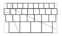
S302において、移動ベクトル抽出部202は、画像取得部201が取得した画像を、複数の小画像に分割する。図4は、画面を小画像に分割する一つの方法を示す図である。図4では、移動ベクトル抽出部202が、各小画像の大きさと、各小画像内に映る人体の大きさと、の比率がほぼ一定となるよう、画像を分割している例を示している。続いて、移動ベクトル抽出部202は、映像解析を行い、小画像ごとの移動ベクトルを抽出する。S302の処理は、画像の範囲ごとに群衆の移動ベクトルを取得処理の一例である。移動ベクトルの取得には種々の方法を用いることができる。
移動ベクトル取得方法の一つ目は、人体検出と人体追尾とを組み合せる方法である。
人体検出とは、画像中の顔や人体の全体又はその一部等、予め定められた部位の位置を特定する処理であり、既知のパターン認識や機械学習の各種手法を利用して実現される。
人体追尾とは、時間的に連続する画像間のそれぞれに対して人体検出を施して得られた人体検出結果に対して、人体の対応付け処理を行う処理である。対応付け処理は、各画像の人体検出結果のうち、同一人に対応する人体検出結果同士をペアリングするマッチング問題として定式化できる。まず、移動ベクトル抽出部202は、人体検出結果間の類似度を、人体を表す図形の位置やサイズ、画像から抽出された特徴量等任意の値を使って定義する。次に、移動ベクトル抽出部202は、最も類似度の高い人体検出結果の組から順番にペアを作る方法や、全体の類似度の和が最大になるようペアを作る全体最適化方法を用いて、人体検出結果のマッチングを決定することができる。移動ベクトル抽出部202は、対応付けされた人体検出結果には同一のIDを付与し、人体追尾結果とする。
図5は、対応付けの一例を示す図である。図5(a)は、時刻t1において取得した画像に対して人体検出を施した結果である。また、図5(b)は、時刻t1から所定の微小時間(例えば1/5秒)が経過した時刻t2において取得した画像に対して人体検出を施した結果である。矩形501、矩形502、矩形503及び矩形504が検出された人体に相当する。人体追尾を行うことで、矩形501と矩形503とにID1が、また矩形502と矩形504とにID2が与えられる。同一のIDが付与された矩形の移動前の位置と移動後の位置とを結んだものが移動ベクトルとなる。図5の場合、矩形501の中心を始点、矩形503の中心を終点として結んだ矢印505が移動ベクトルとなる。同様に、矩形502の中心を始点、矩形504の中心を終点として結んだ矢印506が移動ベクトルとなる。
FIG. 3 is a flowchart showing an example of information processing by the
In S301, the
In S302, the moving
The first method of acquiring the movement vector is a method of combining human body detection and human body tracking.
Human body detection is a process for identifying the position of a predetermined part such as the face in an image or the whole or a part of the human body, and is realized by using various known pattern recognition and machine learning methods. ..
The human body tracking is a process of associating a human body with respect to a human body detection result obtained by performing human body detection for each of images that are continuous in time. The matching process can be formulated as a matching problem of pairing the human body detection results corresponding to the same person among the human body detection results of each image. First, the movement
FIG. 5 is a diagram showing an example of mapping. FIG. 5A is a result of performing human body detection on the image acquired at time t1. Further, FIG. 5B is a result of performing human body detection on an image acquired at a time t2 in which a predetermined minute time (for example, 1/5 second) has elapsed from the time t1.
移動ベクトル取得方法の二つ目は、時間的に連続する複数の小画像を入力として、群衆の密度分布と移動ベクトルの分布とを推定する推定器を用いる方法である。画像中の人物の密度分布及び移動ベクトルの分布を推定する方法としては、例えば、文献「Walach E., Wolf L. (2016) Learning to Count with CNN Boosting. In: Leibe B., Matas J., Sebe N., Welling M. (eds) Computer Vision - ECCV 2016. ECCV 2016. Lecture Notes in Computer Science, vol 9906. Springer, Cham」に記載されている方法を用いることができる。この文献では事前に機械学習によって得たニューラルネットワークを用いて、画像から人物の密度分布を求める。本実施形態ではこの方法を応用し、連続する2フレームの小画像を入力して画像中の人物の密度分布及び移動ベクトルの分布を同時推定するニューラルネットワークを事前に学習し、推定に用いる。図6は、移動ベクトル抽出部202の機能の一例を示す図である。図6中、ニューラルネットの出力のうち、人物密度分布は濃淡の濃い部分が人物頭部の位置を表す。移動ベクトルは濃淡の濃い値ほど移動量が大きいことを表す。図6の例では、群衆の横方向への移動のため、横方向の移動ベクトルは大きく、縦方向の移動ベクトルは小さい値を持つ。また、密度分布は、ある範囲における密度分布の値の和をとると、その範囲に存在する人物の人数とほぼ等しくなるように設計しておく。
図7は、推定器により推定された、ある小画像における人物の密度分布及び移動ベクトルの分布の一例を示す図である。移動ベクトル抽出部202は、横方向移動ベクトルと、縦方向移動ベクトルとを合成することで、移動ベクトルを抽出することができる。移動ベクトルは、密度分布の値と等しい重みをもつ。図7の例では、小画像中に、7本の重み付き移動ベクトルが得られる。
以上、二つの移動ベクトル取得方法について説明した。移動ベクトルを高精度に抽出するためには、群衆の密集度が小さい場合は一つ目の方法を用い、群衆の密集度が大きい場合は二つ目の方法を用いることができる。また、移動ベクトル取得方法はこれらに限定されるものではなく、任意の方法を用いることができる。
The second method of acquiring the movement vector is a method using an estimator that estimates the density distribution of the crowd and the distribution of the movement vector by inputting a plurality of small images that are continuous in time. As a method for estimating the density distribution and the movement vector distribution of a person in an image, for example, the reference "Walach E., Wolf L. (2016) Learning to Count with CNN Boosting. In: Leibe B., Matas J., Sebe N., Welling M. (eds) Computer Vision-ECCV 2016. ECCV 2016. Lecture Notes in Computer Science, vol 9906. Springer, Cham. In this document, the density distribution of a person is obtained from an image by using a neural network obtained by machine learning in advance. In this embodiment, this method is applied, and a neural network that simultaneously estimates the density distribution and movement vector distribution of a person in an image by inputting small images of two consecutive frames is learned in advance and used for estimation. FIG. 6 is a diagram showing an example of the function of the moving
FIG. 7 is a diagram showing an example of the density distribution and the movement vector distribution of a person in a small image estimated by an estimator. The movement
The two movement vector acquisition methods have been described above. In order to extract the movement vector with high accuracy, the first method can be used when the crowd density is small, and the second method can be used when the crowd density is large. Further, the movement vector acquisition method is not limited to these, and any method can be used.
S303において、人流抽出部203は、移動ベクトル抽出部202によって小画像ごとに推定された移動ベクトルを受け取る。続いて、人流抽出部203は、小画像ごとに移動ベクトルをクラスタリングし、移動ベクトルをいくつかのクラスタに分割することで、人流クラスタを得る。
移動ベクトルのクラスタリングは、任意の方法で行うことができる。以下では、ヒストグラムを用いる方法について説明する。最初に、人流抽出部203は、移動ベクトル抽出部202によって取得された各移動ベクトルのうち、その長さが所定の閾値以上である移動ベクトルから、その向きに基づくヒストグラムを生成する。ここで、人流抽出部203は、移動ベクトルに重みが付いている場合は、その重みを考慮して頻度をカウントする。図8は、30度ごとに階級を区切ったヒストグラムの一例を示す図である。
次に、このヒストグラムにおいて値が極大となる階級、即ち隣り合う二つの階級の何れの度数よりも大きな度数を持つ階級を探す。ここで、角度の周期性より、「0度以上30度未満」の階級と「330度以上360度未満」の階級とは連続しているものとみなす。図8の例では、「120度以上150度未満」の階級、「210度以上240度未満」の階級及び「330度以上360度未満」の階級が極大である。
In S303, the human
Clustering of movement vectors can be performed by any method. In the following, a method using a histogram will be described. First, the human
Next, in this histogram, the class having the maximum value, that is, the class having a frequency larger than that of either of the two adjacent classes is searched for. Here, from the periodicity of the angle, it is considered that the class of "0 degrees or more and less than 30 degrees" and the class of "330 degrees or more and less than 360 degrees" are continuous. In the example of FIG. 8, the class of "120 degrees or more and less than 150 degrees", the class of "210 degrees or more and less than 240 degrees", and the class of "330 degrees or more and less than 360 degrees" are the maximum.
次に、人流抽出部203は、値が極大となる階級のうち、瑣末な階級を除去する。例えば、人流抽出部203は、その度数が閾値未満である階級を瑣末な階級であるとして除去する。閾値が15とすると、図8の例では、「210度以上240度未満」の階級が除去され、二つの階級が残る。階級の除去方法はこれに限定されない。例えば、人流抽出部203は、「その階級の度数を全階級の度数の和で除した値」が閾値以下であるか否かによって階級を除去する方法をとってもよい。この処理により残った階級を極大階級と呼ぶ。
次に、人流抽出部203は、各極大階級に対応する人流クラスタを生成する。人流抽出部203は、人流クラスタを、各極大階級又はその極大階級の周辺に位置する階級に属する移動ベクトルの集合から生成する。どの階級までを周辺と定義するかにはいくつかの方法がある。一つ目の方法は、極大階級の前後N個(Nは0以上の整数)の階級までを周辺と定義する方法である。例えば、図8にて前後1個の階級までを周辺と定義した場合、「A」と記した3つの階級に属する移動ベクトルの集合が一つ目の人流クラスタ、「B」と記した3つの階級に属する移動ベクトルの集合が二つ目の人流クラスタとなる。二つ目の方法は、極大階級の周囲にある階級のうち、極大階級の度数に所定の係数をかけた値より大きな度数を持つ階級までを周辺と定義する方法である。
次に、人流抽出部203は、各人流クラスタについて、構成人数、速度、方向等の統計値を計算する。構成人数は、人流クラスタを構成する移動ベクトルの数により得られる。速度は、人流クラスタを構成する移動ベクトルの大きさの平均値や、中央値を取ることにより求められる。方向も速度と同様、人流クラスタを構成する移動ベクトルの方向の平均値や、中央値を取ることにより求められる。以上の処理により、方向付き人流クラスタが得られる。この方向付き人流クラスタを生成する処理は、移動ベクトルに従って、同じ方向に移動する群衆から方向付き人流クラスタを生成する処理の一例である。
人流抽出部203は、方向付き人流クラスタについて、各領域につき最大値を定めてもよい。例えば、人流抽出部203は、各領域につき、方向付き人流クラスタは最大2個までしか出力しないようにしてもよい。その場合、人流抽出部203は、構成人数が多い人流クラスタから順に採用する。この方向付き人流クラスタを生成する処理も、移動ベクトルに従って、同じ方向に移動する群衆から方向付き人流クラスタを生成する処理の一例である。
人流のクラスタリングは、上記の方法に限定されない。例えば、人流抽出部203は、k−means法や階層的手法等、既知のクラスタ分析手法を用いても行うことができる。
ところで、長さがある所定の閾値未満である移動ベクトル、つまりほぼ動きのない頭部に対応する移動ベクトルは、「滞留」と呼ぶ特別な階級に属させる。人流抽出部203は、もし滞留階級の度数が閾値以上であった場合は、これも一つの独立した人流クラスタとする。閾値が15とすると、図8の例では、滞留階級の度数が閾値以上であるため、滞留階級に属する移動ベクトルの集合が三つ目の人流クラスタとなる。以降、このように生成された人流クラスタを滞留クラスタと呼ぶ。この滞留クラスタを生成する処理は、移動ベクトルに従って、同位置に滞留する群衆から滞留クラスタを生成する処理の一例である。
人流のクラスタリングが困難な場合について述べる。群衆を構成する個人が乱雑に動き回り、移動ベクトルの方向に傾向がない場合は、図9のように、どの方向にもほぼ均等に移動ベクトルが出現する。このように、人流抽出部203は、各階級における移動ベクトルの度数の分散が小さい場合は、「乱雑」と呼ぶ特別な人流クラスタを一つ生成する。以降、このように生成した人流クラスタを乱雑クラスタと呼ぶ。この乱雑クラスタを生成する処理は、移動ベクトルに従って、乱雑な方向に移動する群衆から乱雑クラスタを生成する処理の一例である。
Next, the human
Next, the human
Next, the person flow
The person
Human flow clustering is not limited to the above method. For example, the human
By the way, a movement vector whose length is less than a predetermined threshold value, that is, a movement vector corresponding to a head having almost no movement, belongs to a special class called "retention". If the frequency of the retention class is equal to or higher than the threshold value, the human
The case where clustering of human flow is difficult will be described. When the individuals constituting the crowd move around randomly and there is no tendency in the direction of the movement vector, the movement vector appears almost evenly in all directions as shown in FIG. In this way, the human
S304において、人流抽出部203は、現在が学習期間中か否かを判定する。学習期間は、例えば毎月の最初の一週間等固定された期間であることもがあれば、ユーザが明示的に指定することもある。また、直近の15分における人流クラスタの発生確率を常に計算する必要がある場合は、常に学習期間とする。人流抽出部203は、現在が学習期間中だと判定された場合はS305へ、学習期間でないと判定された場合はS306へ進む。
S305において、人流学習部204は、人流抽出部203により得られた人流クラスタを、学習期間において収集する。そして、人流学習部204は、収集した人流クラスタから、人流クラスタの発生確率を統計的に得る。
図10は、人流学習部204が学習した人流クラスタの発生確率の一例を示す図である。図10の例では、人流学習部204は、3時間おきに人流クラスタの発生確率を学習する。図10の例では、平日の朝6時から朝9時の間に、小画像1にて、向きが0度以上30度未満であるような人流クラスタが45%の割合で発生したことが分かる。
また、人流学習部204は、直近のある所定の時間における人流クラスタの発生確率を統計的に得るようにしてもよい。例えば、人流学習部204は、直近の15分における人流クラスタの発生確率を常に計算しておくようにできる。
In S304, the human
In S305, the human
FIG. 10 is a diagram showing an example of the occurrence probability of the human flow cluster learned by the human
In addition, the human
S306において、異常人流判定部205は、人流学習部204により得られた人流クラスタのそれぞれについて、正常か異常かを判定する。異常人流判定部205は、人流学習部204により学習された、人流クラスタの発生確率に基づき、発生確率が低い人流が発生した際に、異常だと判定する。以下では、異常と判定する閾値を10%とする。例えば、平日の朝8時に、小画像1にて15度の向きに移動する人流クラスタが発生したとき、このような人流クラスタの発生確率は図10によると45%であるため、この人流クラスタは正常である、と判定される。同時刻に、小画像2にて15度の向きに移動する人流クラスタが発生したとき、このような人流クラスタの発生確率は図10によると5%であるため、この人流クラスタは異常である、と判定される。
異常人流判定部205は、人流クラスタを正常か異常かの2値で分類するのではなく、人流クラスタが異常である確率、即ち異常度を出力するようにしてもよい。この処理は、異常人流判定部205は、人流クラスタの異常度を取得する異常度取得処理の一例である。例えば、異常人流判定部205は、発生確率がxである人流クラスタが発生したとき、人流クラスタの異常度を1−xとして返すようにすることができる。
異常人流判定部205は、人流学習部204により学習された人流クラスタの発生確率を使わずに、注目する小画像の人流クラスタが正常か異常かを判定するようにしてもよい。例えば、異常人流判定部205は、一方通行で群衆が動くことが期待されるような環境においては、ある小領域で複数の方向付き人流クラスタが発生することは異常だと判定できる。又は、異常人流判定部205は、注目する小画像の周囲にある小画像で発生した人流クラスタを用いて、注目する小画像の人流クラスタが正常か異常かを判定するようにしてもよい。例えば、異常人流判定部205は、注目する小画像において、その周辺に存在する小画像において発生した人流クラスタの何れとも異なる方向を持つ方向付き人流クラスタが発生した場合、その人流クラスタを異常と判定する。
また、異常人流判定部205は、人流学習部204により学習された人流クラスタの発生確率、及び、注目する小画像の周囲にある小画像で発生した人流クラスタの両方を用いて、注目する小画像の人流クラスタが正常か異常かを判定するようにしてもよい。
In S306, the abnormal human
The abnormal person flow
The abnormal human
Further, the abnormal human
S307において、表示部206は、人流抽出部203により得られた人流クラスタを表示する。図11は、人流クラスタに対応するアイコンの一例を示す図である。図11(a)のアイコンは、方向付き人流クラスタを意味する。矢印の向きで人流の方向を表す。更に、表示部206は、矢印の太さで人流の構成人数を、矢印の長さで人流の速度を表すようにしてもよい。また、表示部206は、人流の構成人数を、矢印の近傍に数字で重畳してもよい。図11(b)のアイコンは、滞留クラスタを意味する。表示部206は、丸の半径や色により、滞留クラスタの構成人数や、滞留の平均時間を表すようにしてもよい。図11(c)のアイコンは、乱雑クラスタを意味する。表示部206は、アイコンの半径や色により、乱雑クラスタの構成人数や乱雑度合いを表すようにしてもよい。人流クラスタとアイコンとの対応付けはこれらの方法に限定されず、任意の方法をとってよい。
表示部206は、異常人流判定部205により判定された、正常な人流クラスタと、異常な人流クラスタとを、視覚的に判別できる形で表示する。より具体的には、表示部206は、アイコンの色や太さ、透明度、彩度、輪郭の太さ等で正常と異常とを区別して表示する。又は、表示部206は、アイコンに網掛け処理を施すことで正常と異常を区別する。又は、表示部206は、異常な人流であることをアイコンの近傍に文字で明記してもよい。又は、表示部206は、異常な人流が発生した小画像の枠内全体に対して、視覚的に判別可能な処理を施してもよい。ここで、アイコンとは、ある意味を文字や図、絵で表している画像である。
In S307, the
The
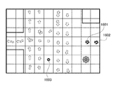
図12は、表示部206による表示の一例を示す図である。表示部206は、各小画像に、小画像ごとに得られた各種人流クラスタに対応するアイコンを重畳する。表示部206は、小画像に複数の人流クラスタが存在する場合は、複数のアイコンを重畳する。
図12のアイコン1201は、異常人流判定部205により異常と判定された、右方向に移動する人流クラスタである。この人流クラスタは、画面の奥側から手前側に向かって現れる人流を横切るように、画面の左側から右側へ移動する人流に対応する。図12のアイコン1202は、異常人流判定部205により異常と判定された、滞留クラスタである。この滞留クラスタは、普段滞留の発生確率が低い場所で起こった滞留に対応する。
また、異常人流判定部205が、人流クラスタの異常度を出力する場合、表示部206は、その確率に応じて、人流を視覚的に判別できる形で表示するようにもできる。例えば、表示部206は、人流クラスタの異常度が高いほど色の彩度を高くアイコンを表示するようにしてもよい。
FIG. 12 is a diagram showing an example of display by the
The
Further, when the abnormal person flow
<実施形態2>
本実施形態では、地図上に、人流を重畳して表示する場合について説明する。本実施形態では、実施形態1と同じ部分については説明を省略し、実施形態1と異なる点について説明する。CPU10がメモリ11に記憶されたプログラムに基づき処理を実行することにより、後述する図13の画像処理装置1300の機能構成及び後述する図14のフローチャートの処理が実現される。
図13は、画像処理装置1300の機能構成の一例を示す図である。図13の画像処理装置1300は、図2の画像処理装置100に、座標変換部1301が新たに加えられたものである。座標変換部1301は、撮像画像上の検出座標から地図上の検出座標に変換する処理を行う。
図14は、画像処理装置1300による情報処理の一例を示すフローチャートである。図14のフローチャートは、図3のフローチャートに、S1401が新たに加えられたものである。
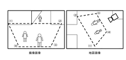
S1401において、座標変換部1301は、撮像画像中の検出座標から地図上の検出座標に変換する処理を行う。座標変換の一つの方法として、対応点に基づいた射影変換がある。座標変換部1301は、図15に示すように撮像画像中の任意の4点と、地図中の任意の4点とを、ユーザに指定させる。これにより撮像画像中の任意の点を地図の対応位置に変換できるよう、射影変換の式を導出することができる。対応点を指定する際は間違った対応付けにならないよう、点を指定する順番に制約を定めておくとよい。例えば「左上起点で時計回り」のように定める。また、座標変換部1301が図15に示したように点を指定した順番を数字で示すことも効果的である。座標変換部1301は、指定された座標点とその順序とが分かれば所定の制約に従って入力されたものか判定することもできる。そのため、制約に違反していた場合、座標変換部1301は、設定の失敗を通知し、再度の入力を促す。複数のカメラが設置されている場合、座標変換部1301は、すべてのカメラに対して地図との対応付けを行う。
座標変換部1301が座標変換処理を施すことで、S302によって抽出された移動ベクトルを、地図上の座標に変換することができる。S303以降の処理をすべて地図上の座標に基づいて行うことで、表示部206は、図16のように、地図上に人流クラスタを重畳して表示することができる。図16では、アイコン1601、1602及び1603が異常な人流クラスタを表し、それ以外のアイコンが正常な人流クラスタを表す。
<
In the present embodiment, a case where a person flow is superimposed and displayed on a map will be described. In the present embodiment, the same parts as those in the first embodiment will be omitted, and the differences from the first embodiment will be described. By executing the process based on the program stored in the
FIG. 13 is a diagram showing an example of the functional configuration of the
FIG. 14 is a flowchart showing an example of information processing by the
In S1401, the coordinate
By performing the coordinate conversion process by the coordinate
<実施形態3>
本実施形態では、異常人流の発生時に、異常人流に関する情報を通知する場合について説明する。本実施形態では、実施形態1と同じ部分については説明を省略し、実施形態1と異なる点について説明する。CPU10がメモリ11に記憶されたプログラムに基づき処理を実行することにより、後述する図17の画像処理装置1700の機能構成及び後述する図18のフローチャートの処理が実現される。
図17は、画像処理装置1700の一例を示す図である。図17は、図2の画像処理装置100から表示部206を除き、通知部1701及び記録部1702を新たに加えたものである。通知部1701は、異常人流判定部205により異常人流が発生したとき、異常人流に関する情報を、ネットワークI/F12を通じて外部に通知する処理を行う。記録部1702は、人流抽出部203によって抽出された人流クラスタに関する情報をメモリ11に保存する。
図18は、画像処理装置1700による情報処理の一例を示すフローチャートである。図18は、図3のフローチャートからS307を取り除き、S1801及びS1802を新たに加えたものである。
S1801において、通知部1701は、異常人流判定部205により異常と判定された人流クラスタが発生したとき、異常人流クラスタに関する情報を、ネットワークI/F12を通じて外部に通知する処理を行う。異常人流クラスタに関する情報には、異常人流クラスタの画面上又は地図上における発生場所、人流クラスタを構成する人数、人流クラスタの移動方向、人流クラスタの移動速度の少なくとも一つを含む。
異常人流の発生時に通知を行うことで、警備員に異常の発生をいち早く知らせたり、異常発生時の映像を録画して保存したりといった処置が可能となる。
S1802において、記録部1702は、人流抽出部203によって抽出された人流クラスタに関する情報をメモリ11に保存する。人流クラスタに関する情報には、人流クラスタの画面上又は地図上における発生場所、人流クラスタの発生時刻、人流クラスタが正常か異常の何れか(又は異常度)、人流クラスタを構成する人数、人流クラスタの移動方向、人流クラスタの移動速度の少なくとも一つを含む。また、記録部1702は、異常人流判定部205により異常と判定された人流クラスタに関する情報のみを保存しておくようにしてもよい。人流クラスタに関する情報を保存しておくことにより、後で異常な人流が発生した場面に絞って映像を検索すること等が可能になる。
<
In this embodiment, a case of notifying information about an abnormal person flow when an abnormal person flow occurs will be described. In the present embodiment, the same parts as those in the first embodiment will be omitted, and the differences from the first embodiment will be described. By executing the processing based on the program stored in the
FIG. 17 is a diagram showing an example of the
FIG. 18 is a flowchart showing an example of information processing by the
In S1801, the
By notifying when an abnormal person flow occurs, it is possible to take measures such as promptly notifying the guards of the occurrence of the abnormality and recording and saving the video at the time of the occurrence of the abnormality.
In S1802, the
<その他の実施形態>
本発明は、上述の実施形態の1以上の機能を実現するプログラムを、ネットワーク又は記憶媒体を介してシステム又は装置に供給する。そして、そのシステム又は装置のコンピュータにおける1つ以上のプロセッサーがプログラムを読み出し実行する処理でも実現可能である。また、1以上の機能を実現する回路(例えば、ASIC)によっても実現可能である。
<Other embodiments>
The present invention supplies a system or device via a network or storage medium a program that realizes one or more of the functions of the above-described embodiment. It can also be realized by a process in which one or more processors in the computer of the system or apparatus reads and executes a program. It can also be realized by a circuit (for example, ASIC) that realizes one or more functions.
以上、本発明の実施形態の一例について詳述したが、本発明は係る特定の実施形態に限定されるものではない。
例えば、画像処理装置100のハードウェア構成として、CPUは複数存在してもよく、複数のCPUがメモリに記憶されているプログラムに基づき処理を実行するようにしてもよい。また、画像処理装置100のハードウェア構成として、CPUに替えてGPU(Graphics Processing Unit)を用いることとしてもよい。
また、画像処理装置100の機能構成の一部又はすべてはハードウェア構成として画像処理装置100に実装されてもよい。
また、上述した実施形態を任意に組み合わせて実施してもよい。
Although an example of the embodiment of the present invention has been described in detail above, the present invention is not limited to the specific embodiment.
For example, as a hardware configuration of the
Further, a part or all of the functional configurations of the
Further, the above-described embodiments may be arbitrarily combined and carried out.
以上、上述した各実施形態の処理によれば、異常な人流を検出し、その人流に関する情報をユーザに提示可能とすることができる。 As described above, according to the processing of each of the above-described embodiments, it is possible to detect an abnormal flow of people and present information about the flow of people to the user.
10 CPU
11 メモリ
12 ネットワークI/F
13 表示装置
14 入力装置
10 CPU
11
13
Claims (16)
前記取得手段により取得された移動ベクトルに基づいて、所定の条件を満たす前記人物の集合であるクラスタを生成する生成手段と、
前記生成されたクラスタのうち、前記部分画像における前記クラスタの発生確率が予め記憶された所定の値より小さいクラスタを出力する出力手段と、
を有する画像処理装置。 An acquisition method for acquiring a movement vector representing the movement of a person for each partial image of an image,
Based on the movement vector acquired by the acquisition means, a generation means for generating a cluster which is a set of the persons satisfying a predetermined condition, and a generation means.
An output means for outputting a cluster in which the probability of occurrence of the cluster in the partial image is smaller than a predetermined value stored in advance among the generated clusters.
Image processing device with.
前記出力手段は、前記方向付き人流クラスタを視覚的に判別可能な形で前記画像に重畳して出力する請求項1記載の画像処理装置。 The generation means generates a directional human flow cluster consisting of people moving in the same direction based on the movement vector acquired by the acquisition means.
The image processing apparatus according to claim 1, wherein the output means superimposes and outputs the directed person flow cluster on the image in a form that can be visually discriminated.
前記出力手段は、前記滞留クラスタを視覚的に判別可能な形で前記画像に重畳して出力する請求項1又は2記載の画像処理装置。 The generation means generates a retention cluster consisting of people who stay at the same position based on the movement vector acquired by the acquisition means.
The image processing apparatus according to claim 1 or 2, wherein the output means superimposes and outputs the stagnant cluster on the image in a form that can be visually discriminated.
前記出力手段は、前記乱雑クラスタを視覚的に判別可能な形で前記画像に重畳して出力する請求項1乃至3何れか1項記載の画像処理装置。 The generation means generates a messy cluster consisting of people moving in a messy direction based on the movement vector acquired by the acquisition means.
The image processing apparatus according to any one of claims 1 to 3, wherein the output means superimposes and outputs the random cluster on the image in a form that can be visually discriminated.
前記出力手段は、前記クラスタに対し、前記人数を出力する請求項1乃至4何れか1項記載の画像処理装置。 It said generating means obtains the number of people composing the generated cluster,
And the output means, the relative cluster, the image processing apparatus according to claim 1 to 4 any one of claims outputs the number.
前記出力手段は、前記クラスタに対し、前記速度を出力する請求項1乃至4何れか1項記載の画像処理装置。 It said generating means obtains the rate of the generated clusters,
And the output means, the relative cluster, the image processing apparatus according to claim 1 to 4 any one of claims outputting said speed.
前記出力手段は、前記クラスタに対し、前記方向を出力する請求項1乃至4何れか1項記載の画像処理装置。 It said generating means obtains the direction of the generated clusters,
And the output means, the relative cluster, the image processing apparatus according to claim 1 to 4 any one of claims outputting said direction.
前記出力手段は、前記正常なクラスタと前記異常なクラスタを区別して出力する請求項1乃至7何れか1項記載の画像処理装置。 Based on the cluster of probability that is generated by the previous SL generation means further includes a classifying means for classifying the cluster to the normal cluster and an abnormal cluster,
The image processing apparatus according to any one of claims 1 to 7 , wherein the output means distinguishes between the normal cluster and the abnormal cluster.
前記生成手段は、前記地図上の範囲ごとに地図上に変換された移動ベクトルに基づいてクラスタを生成し、
前記出力手段は、前記地図上の範囲ごとに正常なクラスタと異常なクラスタとを視覚的に判別可能な形で重畳して出力する請求項1乃至11何れか1項記載の画像処理装置。 Further having a conversion means for converting the movement vector acquired by the acquisition means on the map by converting the coordinates on the image to the coordinates on the map.
It said generating means generates the cluster based on the movement vector converted on the map for each area on the map,
The image processing apparatus according to any one of claims 1 to 11, wherein the output means superimposes and outputs a normal cluster and an abnormal cluster for each range on the map in a visually discriminable manner.
前記出力手段は、前記クラスタの異常度を視覚的に判別可能な形で前記画像に重畳して表示する請求項1乃至13何れか1項記載の画像処理装置。The image processing apparatus according to any one of claims 1 to 13, wherein the output means superimposes and displays the degree of abnormality of the cluster on the image in a form that can be visually discriminated.
前記取得工程により取得された移動ベクトルに基づいて、所定の条件を満たす前記人物の集合であるクラスタを生成する生成工程と、Based on the movement vector acquired by the acquisition step, a generation step of generating a cluster which is a set of the persons satisfying a predetermined condition, and a generation step.
前記生成工程により生成されたクラスタのうち、前記部分画像における前記クラスタの発生確率が予め記憶された所定の値より小さいクラスタを出力する出力工程と、Among the clusters generated by the generation step, an output step of outputting a cluster in which the probability of occurrence of the cluster in the partial image is smaller than a predetermined value stored in advance, and
を含む画像処理方法。Image processing methods including.
Priority Applications (2)
| Application Number | Priority Date | Filing Date | Title |
|---|---|---|---|
| JP2017193026A JP6968645B2 (en) | 2017-10-02 | 2017-10-02 | Image processing equipment, image processing methods and programs |
| US16/145,651 US10984252B2 (en) | 2017-10-02 | 2018-09-28 | Apparatus and method for analyzing people flows in image |
Applications Claiming Priority (1)
| Application Number | Priority Date | Filing Date | Title |
|---|---|---|---|
| JP2017193026A JP6968645B2 (en) | 2017-10-02 | 2017-10-02 | Image processing equipment, image processing methods and programs |
Publications (3)
| Publication Number | Publication Date |
|---|---|
| JP2019067208A JP2019067208A (en) | 2019-04-25 |
| JP2019067208A5 JP2019067208A5 (en) | 2020-11-12 |
| JP6968645B2 true JP6968645B2 (en) | 2021-11-17 |
Family
ID=65896147
Family Applications (1)
| Application Number | Title | Priority Date | Filing Date |
|---|---|---|---|
| JP2017193026A Active JP6968645B2 (en) | 2017-10-02 | 2017-10-02 | Image processing equipment, image processing methods and programs |
Country Status (2)
| Country | Link |
|---|---|
| US (1) | US10984252B2 (en) |
| JP (1) | JP6968645B2 (en) |
Families Citing this family (14)
| Publication number | Priority date | Publication date | Assignee | Title |
|---|---|---|---|---|
| JP6898165B2 (en) * | 2017-07-18 | 2021-07-07 | パナソニック株式会社 | People flow analysis method, people flow analyzer and people flow analysis system |
| US11200429B1 (en) * | 2018-12-28 | 2021-12-14 | Zoox, Inc. | Tracking objects using sensor data segmentations and/or representations |
| JP7330708B2 (en) * | 2019-01-28 | 2023-08-22 | キヤノン株式会社 | Image processing device, image processing method, and program |
| DE102019202104A1 (en) * | 2019-02-18 | 2020-08-20 | Robert Bosch Gmbh | Display device and monitoring device |
| JP2020170252A (en) * | 2019-04-01 | 2020-10-15 | キヤノン株式会社 | Image processing device, image processing method, and program |
| CN110502967B (en) * | 2019-07-01 | 2020-12-18 | 光控特斯联(上海)信息科技有限公司 | Artificial intelligence matching method and device for target scene based on personnel big data |
| JP7443002B2 (en) * | 2019-09-13 | 2024-03-05 | キヤノン株式会社 | Image analysis device, image analysis method, and program |
| CN111476979A (en) * | 2019-11-21 | 2020-07-31 | 武汉烽火众智数字技术有限责任公司 | Intelligent security and stability maintenance method and system based on multi-model analysis |
| JP7371704B2 (en) * | 2020-02-03 | 2023-10-31 | 日本電気株式会社 | Flow rate information output device, control method, and program |
| CN111401220B (en) * | 2020-03-12 | 2021-03-19 | 重庆特斯联智慧科技股份有限公司 | Crowd aggregation characteristic analysis method and system for intelligent security |
| JP6983275B2 (en) * | 2020-04-28 | 2021-12-17 | 株式会社Agoop | Information processing equipment, information processing methods and programs related to abnormality detection and abnormality degree visualization |
| JP7538631B2 (en) | 2020-06-15 | 2024-08-22 | キヤノン株式会社 | Image processing device, image processing method, and program |
| JP2022076716A (en) * | 2020-11-10 | 2022-05-20 | キヤノン株式会社 | Image processing device, image processing method, and program |
| JP2022091547A (en) * | 2020-12-09 | 2022-06-21 | キヤノン株式会社 | Image processing device, image processing method, and program |
Family Cites Families (12)
| Publication number | Priority date | Publication date | Assignee | Title |
|---|---|---|---|---|
| JPH03195922A (en) * | 1989-12-25 | 1991-08-27 | Mitsubishi Electric Corp | Detecting apparatus for degree of congestion |
| US6549681B1 (en) | 1995-09-26 | 2003-04-15 | Canon Kabushiki Kaisha | Image synthesization method |
| JP3869876B2 (en) | 1995-12-19 | 2007-01-17 | キヤノン株式会社 | Image measuring method and image measuring apparatus |
| EP0908847B1 (en) | 1997-10-06 | 2006-01-25 | Canon Kabushiki Kaisha | Image synthesis apparatus and image synthesis method |
| US6704041B2 (en) | 1998-03-10 | 2004-03-09 | Canon Kabushiki Kaisha | Image processing method, apparatus and memory medium therefor |
| JP5763965B2 (en) | 2011-05-11 | 2015-08-12 | キヤノン株式会社 | Information processing apparatus, information processing method, and program |
| JP6341650B2 (en) | 2013-11-20 | 2018-06-13 | キヤノン株式会社 | Image processing apparatus, image processing method, and program |
| JP6299299B2 (en) * | 2014-03-14 | 2018-03-28 | オムロン株式会社 | Event detection apparatus and event detection method |
| JP2015194915A (en) * | 2014-03-31 | 2015-11-05 | 住友電気工業株式会社 | Moving body tracking apparatus, moving body tracking method, moving body tracking system, and camera |
| JP6611302B2 (en) * | 2015-02-20 | 2019-11-27 | 株式会社竹中工務店 | Seismic isolation device installation structure |
| JP6336952B2 (en) * | 2015-09-30 | 2018-06-06 | セコム株式会社 | Crowd analysis device |
| US10936882B2 (en) * | 2016-08-04 | 2021-03-02 | Nec Corporation | People flow estimation device, display control device, people flow estimation method, and recording medium |
-
2017
- 2017-10-02 JP JP2017193026A patent/JP6968645B2/en active Active
-
2018
- 2018-09-28 US US16/145,651 patent/US10984252B2/en active Active
Also Published As
| Publication number | Publication date |
|---|---|
| US10984252B2 (en) | 2021-04-20 |
| JP2019067208A (en) | 2019-04-25 |
| US20190102630A1 (en) | 2019-04-04 |
Similar Documents
| Publication | Publication Date | Title |
|---|---|---|
| JP6968645B2 (en) | Image processing equipment, image processing methods and programs | |
| JP7130368B2 (en) | Information processing device and information processing system | |
| Benedek et al. | Lidar-based gait analysis and activity recognition in a 4d surveillance system | |
| JP6655878B2 (en) | Image recognition method and apparatus, program | |
| JP6555906B2 (en) | Information processing apparatus, information processing method, and program | |
| US20200184228A1 (en) | People flow estimation device, display control device, people flow estimation method, and recording medium | |
| JP5218168B2 (en) | Imaging device, moving object detection method, moving object detection circuit, program, and monitoring system | |
| US10110801B2 (en) | Methods and systems for controlling a camera to perform a task | |
| EP2693404A1 (en) | Person tracking device, person tracking method, and non-temporary computer-readable medium storing person tracking program | |
| US20110135153A1 (en) | Image processing device, image processing method and program | |
| Avgerinakis et al. | Recognition of activities of daily living for smart home environments | |
| US9245247B2 (en) | Queue analysis | |
| TW201137767A (en) | Image processing apparatus and image processing method | |
| Lin et al. | Visual-attention-based background modeling for detecting infrequently moving objects | |
| Mahbub et al. | An optical flow based approach for action recognition | |
| Poonsri et al. | Improvement of fall detection using consecutive-frame voting | |
| Lin et al. | Co-interest person detection from multiple wearable camera videos | |
| Zaidi et al. | Video anomaly detection and classification for human activity recognition | |
| Iazzi et al. | Fall detection based on posture analysis and support vector machine | |
| Wang et al. | Pedestrian detection in crowded scenes via scale and occlusion analysis | |
| JP2017076181A (en) | Tracking device | |
| Ilao et al. | Crowd estimation using region-specific HOG With SVM | |
| KR20160068281A (en) | Method of object recognition | |
| JP2019029747A (en) | Image monitoring system | |
| JP2005250692A (en) | Method for identifying object, method for identifying mobile object, program for identifying object, program for identifying mobile object, medium for recording program for identifying object, and medium for recording program for identifying traveling object |
Legal Events
| Date | Code | Title | Description |
|---|---|---|---|
| A521 | Request for written amendment filed |
Free format text: JAPANESE INTERMEDIATE CODE: A523 Effective date: 20200917 |
|
| A621 | Written request for application examination |
Free format text: JAPANESE INTERMEDIATE CODE: A621 Effective date: 20200917 |
|
| TRDD | Decision of grant or rejection written | ||
| A01 | Written decision to grant a patent or to grant a registration (utility model) |
Free format text: JAPANESE INTERMEDIATE CODE: A01 Effective date: 20210928 |
|
| A61 | First payment of annual fees (during grant procedure) |
Free format text: JAPANESE INTERMEDIATE CODE: A61 Effective date: 20211027 |
|
| R151 | Written notification of patent or utility model registration |
Ref document number: 6968645 Country of ref document: JP Free format text: JAPANESE INTERMEDIATE CODE: R151 |