JP6967750B2 - Motor control device and control method of motor control device - Google Patents
Motor control device and control method of motor control device Download PDFInfo
- Publication number
- JP6967750B2 JP6967750B2 JP2018171282A JP2018171282A JP6967750B2 JP 6967750 B2 JP6967750 B2 JP 6967750B2 JP 2018171282 A JP2018171282 A JP 2018171282A JP 2018171282 A JP2018171282 A JP 2018171282A JP 6967750 B2 JP6967750 B2 JP 6967750B2
- Authority
- JP
- Japan
- Prior art keywords
- control
- motor
- abnormality
- inverter
- power supply
- Prior art date
- Legal status (The legal status is an assumption and is not a legal conclusion. Google has not performed a legal analysis and makes no representation as to the accuracy of the status listed.)
- Active
Links
- 238000000034 method Methods 0.000 title claims description 36
- 230000005856 abnormality Effects 0.000 claims description 563
- 230000003313 weakening effect Effects 0.000 claims description 73
- 230000002159 abnormal effect Effects 0.000 claims description 71
- 238000001514 detection method Methods 0.000 claims description 25
- 230000004044 response Effects 0.000 claims description 14
- 230000002547 anomalous effect Effects 0.000 claims description 4
- 230000008569 process Effects 0.000 description 20
- 239000003990 capacitor Substances 0.000 description 13
- 230000001276 controlling effect Effects 0.000 description 12
- 238000009499 grossing Methods 0.000 description 11
- 230000001360 synchronised effect Effects 0.000 description 10
- 238000006243 chemical reaction Methods 0.000 description 8
- 230000001172 regenerating effect Effects 0.000 description 8
- 101100208381 Caenorhabditis elegans tth-1 gene Proteins 0.000 description 7
- 230000000694 effects Effects 0.000 description 7
- 230000007423 decrease Effects 0.000 description 6
- 238000010586 diagram Methods 0.000 description 6
- 230000005540 biological transmission Effects 0.000 description 5
- 230000007246 mechanism Effects 0.000 description 5
- 230000006399 behavior Effects 0.000 description 4
- 230000006870 function Effects 0.000 description 3
- 230000007274 generation of a signal involved in cell-cell signaling Effects 0.000 description 3
- 230000005669 field effect Effects 0.000 description 2
- 230000004907 flux Effects 0.000 description 2
- 230000006872 improvement Effects 0.000 description 2
- 230000003071 parasitic effect Effects 0.000 description 2
- 230000001105 regulatory effect Effects 0.000 description 2
- 239000004065 semiconductor Substances 0.000 description 2
- HBBGRARXTFLTSG-UHFFFAOYSA-N Lithium ion Chemical compound [Li+] HBBGRARXTFLTSG-UHFFFAOYSA-N 0.000 description 1
- 230000005347 demagnetization Effects 0.000 description 1
- 238000009795 derivation Methods 0.000 description 1
- 229910001416 lithium ion Inorganic materials 0.000 description 1
- 239000000463 material Substances 0.000 description 1
- 230000004048 modification Effects 0.000 description 1
- 238000012986 modification Methods 0.000 description 1
Images


Description
この開示は、モータ制御装置およびモータ制御装置の制御方法に関する。 This disclosure relates to a motor control device and a control method for the motor control device.
従来、直流電源の電力によりモータを制御するモータ制御装置が知られている。このようなモータ制御装置の一例として、特許文献1には、電池を電源として電圧形インバータを介して車両駆動用の永久磁石形同期電動機を駆動する電気自動車の電気システムが開示されている。この電気自動車の電気システムでは、車両走行中に電池からインバータに至る直流回路が開放されるような異常発生時に、インバータの上側アームまたは下側アームのスイッチング素子を一括してオンさせることにより、同期電動機の入力端子を短絡してインバータからの電力供給を停止するようになっている。
Conventionally, a motor control device that controls a motor by the electric power of a DC power source is known. As an example of such a motor control device,
しかしながら、特許文献1の電気システムはモータ制御装置として改善の余地がある。
However, the electric system of
例えば、特許文献1の電気システムでは、異常が発生してインバータの上側アームまたは下側アームのスイッチング素子を一括してオンさせるという制御が行われているときに同期電動機の回転速度が低下すると、同期電動機に作用する回生トルクにより同期電動機の回転速度が急激に低下してしまう可能性がある。なお、異常が発生した場合にインバータの全スイッチング素子をオフさせるという制御を行うことが考えられる。しかしながら、異常が発生してインバータの全スイッチング素子をオフさせるという制御が行われているときに同期電動機の回転速度が上昇すると、同期電動機からインバータを経由して電池側に回生される電力により電源とインバータとを接続する電力線が過電圧(例えば法規制電圧を上回る電圧)となる可能性がある。このように、特許文献1の電気システムでは、同期電動機の急減速および電源とインバータとを接続する電力線の過電圧の両方を抑制することが困難である。
For example, in the electric system of
そこで、本開示では、さらなる改善を図ることが可能なモータ制御装置を提供する。 Therefore, in the present disclosure, a motor control device capable of further improvement is provided.
この開示は、直流電源の電力により三相交流式のモータを制御するモータ制御装置に関し、このモータ制御装置は、前記モータの3つの入力端子にそれぞれ接続される3つの出力線と前記直流電源の正極に接続される電源線との間にそれぞれ接続される3つのハイサイドスイッチング素子と、該3つの出力線と該直流電源の負極に接続される接地線との間にそれぞれ接続される3つのローサイドスイッチング素子とを有するインバータと、前記インバータのスイッチング動作の制御に用いられる情報を検知するセンサと、制御部とを備えている。前記制御部は、前記直流電源と前記モータと前記インバータと前記センサのうち少なくとも1つに対して異常判定を行い、前記異常判定により異常があると判定されるまで、前記センサにより検知された情報に基づいて前記インバータのスイッチング動作を制御する通常制御を行い、前記異常判定により異常があると判定された後の異常継続期間において、前記モータに作用するトルクに応じて、前記3つのハイサイドスイッチング素子からなるハイサイドスイッチング素子群および前記3つのローサイドスイッチング素子からなるローサイドスイッチング素子群のうち一方のスイッチング素子群をオン状態にするとともに他方のスイッチング素子群をオフ状態にする三相短絡制御と該ハイサイドスイッチング素子群および該ローサイドスイッチング素子群の全部をオフ状態にする全開放制御のいずれか一方を行う。前記制御部は、さらに、前記直流電源と前記モータと前記インバータと前記センサとに対して異常判定を行う異常判定部と、前記異常判定部により前記直流電源と前記モータと前記インバータと前記センサのうち少なくとも1つが異常であると判定されるまで、前記センサにより検知された情報に基づいて前記インバータのスイッチング動作を制御する通常制御部と、異常制御部と、を有する。前記異常制御部は、前記異常判定部により前記直流電源と前記モータと前記インバータと前記センサのうち少なくとも1つが異常であると判定される前に、前記モータの動作状態に応じて前記三相短絡制御と前記全開放制御のいずれか一方を選択する異常制御選択部と、前記異常判定部により前記直流電源と前記モータと前記インバータと前記センサのうち少なくとも1つが異常であると判定されると、前記三相短絡制御と前記全開放制御のうち前記異常制御選択部により選択された制御を行う異常制御実行部と、を有している。
また、この開示は、直流電源の電力により三相交流式のモータを制御するモータ制御装置であって、前記モータの3つの入力端子にそれぞれ接続される3つの出力線と前記直流電源の正極に接続される電源線との間にそれぞれ接続される3つのハイサイドスイッチング素子と、該3つの出力線と該直流電源の負極に接続される接地線との間にそれぞれ接続される3つのローサイドスイッチング素子とを有するインバータと、前記インバータのスイッチング動作の制御に用いられる情報を検知するセンサと、前記直流電源と前記モータと前記インバータと前記センサとに対して異常判定を行う異常判定部と、前記異常判定部により前記直流電源と前記モータと前記インバータと前記センサのうち少なくとも1つが異常であると判定されるまで、前記センサにより検知された情報に基づいて前記インバータのスイッチング動作を制御する通常制御部と、前記異常判定部により前記直流電源と前記モータと前記インバータと前記センサのうち少なくとも1つが異常であると判定されると、該モータの動作状態に応じて、前記3つのハイサイドスイッチング素子からなるハイサイドスイッチング素子群および前記3つのローサイドスイッチング素子からなるローサイドスイッチング素子群のうち一方のスイッチング素子群をオン状態にするとともに他方のスイッチング素子群をオフ状態にする三相短絡制御と該ハイサイドスイッチング素子群および該ローサイドスイッチング素子群の全部をオフ状態にする全開放制御のいずれか一方を選択して行う異常制御部とを備え、前記異常制御部は、前記異常判定部により前記直流電源と前記モータと前記インバータと前記センサのうち少なくとも1つが異常であると判定される前に、前記モータの動作状態に応じて前記三相短絡制御と前記全開放制御のいずれか一方を選択する異常制御選択部と、前記異常判定部により前記直流電源と前記モータと前記インバータと前記センサのうち少なくとも1つが異常であると判定されると、前記三相短絡制御と前記全開放制御のうち前記異常制御選択部により選択された制御を行う異常制御実行部とを有している。
This disclosure relates to a motor control device that controls a three-phase AC type motor by the power of a DC power source, and the motor control device includes three output lines connected to three input terminals of the motor and the DC power supply. Three high-side switching elements connected to the power supply line connected to the positive side, and three connected to the ground line connected to the negative side of the DC power supply and the three output lines. It includes an inverter having a low-side switching element, a sensor for detecting information used for controlling the switching operation of the inverter, and a control unit. The control unit determines an abnormality in at least one of the DC power supply, the motor, the inverter, and the sensor, and the information detected by the sensor until the abnormality determination determines that there is an abnormality. The normal control for controlling the switching operation of the inverter is performed based on the above three high-side switching according to the torque acting on the motor in the abnormality continuation period after the abnormality determination determines that there is an abnormality. Three-phase short-circuit control and the three-phase short-circuit control in which one of the high-side switching element group consisting of the elements and the low-side switching element group consisting of the three low-side switching elements is turned on and the other switching element group is turned off. Either one of the high-side switching element group and the fully open control for turning off all of the low-side switching element group is performed. The control unit further includes an abnormality determination unit that determines an abnormality with respect to the DC power supply, the motor, the inverter, and the sensor, and the DC power supply, the motor, the inverter, and the sensor by the abnormality determination unit. It has a normal control unit and an abnormality control unit that control the switching operation of the inverter based on the information detected by the sensor until at least one of them is determined to be abnormal. The abnormality control unit has the three-phase short circuit according to the operating state of the motor before the DC power supply, the motor, the inverter, and at least one of the sensors are determined to be abnormal by the abnormality determination unit. When at least one of the DC power supply, the motor, the inverter, and the sensor is determined to be abnormal by the abnormality control selection unit that selects either control or the fully open control, and the abnormality determination unit. It has an abnormality control execution unit that performs control selected by the abnormality control selection unit among the three-phase short circuit control and the fully open control.
Further, this disclosure is a motor control device that controls a three-phase AC type motor by the power of a DC power supply, and is used for three output lines connected to three input terminals of the motor and a positive electrode of the DC power supply. Three high-side switching elements connected to each of the connected power supply lines and three low-side switching elements connected to each of the three output lines and the ground wire connected to the negative electrode of the DC power supply. An inverter having an element, a sensor that detects information used for controlling the switching operation of the inverter, an abnormality determination unit that determines an abnormality in the DC power supply, the motor, the inverter, and the sensor, and the above. Normal control that controls the switching operation of the inverter based on the information detected by the sensor until at least one of the DC power supply, the motor, the inverter, and the sensor is determined to be abnormal by the abnormality determination unit. When at least one of the DC power supply, the motor, the inverter, and the sensor is determined to be abnormal by the unit and the abnormality determination unit, the three high-side switching elements are determined according to the operating state of the motor. Three-phase short-circuit control and the high are that one of the high-side switching element group consisting of the high-side switching element group and the low-side switching element group consisting of the three low-side switching elements is turned on and the other switching element group is turned off. It is provided with an abnormality control unit that selects and performs either a side switching element group or a fully open control that turns off all of the low side switching element group, and the abnormality control unit is the DC power supply by the abnormality determination unit. An abnormality in which either the three-phase short-circuit control or the fully open control is selected according to the operating state of the motor before at least one of the motor, the inverter, and the sensor is determined to be abnormal. When at least one of the DC power supply, the motor, the inverter, and the sensor is determined to be abnormal by the control selection unit and the abnormality determination unit, the abnormality among the three-phase short circuit control and the fully open control is performed. It has an abnormality control execution unit that performs control selected by the control selection unit.
また、この開示は、三相交流式のモータの3つの入力端子にそれぞれ接続される3つの出力線と直流電源の正極に接続される電源線との間にそれぞれ接続される3つのハイサイドスイッチング素子と、該3つの出力線と該直流電源の負極に接続される接地線との間にそれぞれ接続される3つのローサイドスイッチング素子とを有するインバータと、該インバータのスイッチング動作の制御に用いられる情報を検知するセンサとを備えたモータ制御装置の制御方法に関し、このモータ制御装置の制御方法は、前記直流電源と前記モータと前記インバータと前記センサのうち少なくとも1つに対して異常判定を行う異常判定ステップと、前記異常判定ステップにより異常があると判定されるまで、前記センサにより検知された情報に基づいて前記インバータのスイッチング動作を制御する通常制御ステップと、前記異常判定ステップにより異常があると判定された後の異常継続期間において、前記モータに作用するトルクに応じて、前記3つのハイサイドスイッチング素子からなるハイサイドスイッチング素子群および前記3つのローサイドスイッチング素子からなるローサイドスイッチング素子群のうち一方のスイッチング素子群をオン状態にするとともに他方のスイッチング素子群をオフ状態にする三相短絡制御と該ハイサイドスイッチング素子群および該ローサイドスイッチング素子群の全部をオフ状態にする全開放制御のいずれか一方を行う異常継続対応ステップと、を含む。このモータ制御装置の制御方法は、異常制御ステップを、さらに含み、前記異常制御ステップは、前記異常判定ステップにより前記直流電源と前記モータと前記インバータと前記センサのうち少なくとも1つが異常であると判定される前に、前記モータの動作状態に応じて前記三相短絡制御と前記全開放制御のいずれか一方を選択する異常制御選択ステップと、前記異常判定ステップにより前記直流電源と前記モータと前記インバータと前記センサのうち少なくとも1つが異常であると判定された場合に、前記三相短絡制御と前記全開放制御のうち前記異常制御選択ステップにより選択された制御を行う異常制御実行ステップと、を含む。
また、この開示は、三相交流式のモータの3つの入力端子にそれぞれ接続される3つの出力線と直流電源の正極に接続される電源線との間にそれぞれ接続される3つのハイサイドスイッチング素子と、該3つの出力線と該直流電源の負極に接続される接地線との間にそれぞれ接続される3つのローサイドスイッチング素子とを有するインバータと、該インバータのスイッチング動作の制御に用いられる情報を検知するセンサとを備えたモータ制御装置の制御方法であって、前記直流電源と前記モータと前記インバータと前記センサとに対して異常判定を行う異常判定ステップと、前記異常判定ステップにおいて前記直流電源と前記モータと前記インバータと前記センサのうち少なくとも1つが異常であると判定された場合に、前記モータの動作状態に応じて、前記3つのハイサイドスイッチング素子からなるハイサイドスイッチング素子群および前記3つのローサイドスイッチング素子からなるローサイドスイッチング素子群のうち一方のスイッチング素子群をオン状態にするとともに他方のスイッチング素子群をオフ状態にする三相短絡制御と該ハイサイドスイッチング素子群および該ローサイドスイッチング素子群の全部をオフ状態にする全開放制御のいずれか一方を選択して行う異常制御ステップと、を含み、前記異常制御ステップは、前記異常判定ステップにより前記直流電源と前記モータと前記インバータと前記センサのうち少なくとも1つが異常であると判定される前に、前記モータの動作状態に応じて前記三相短絡制御と前記全開放制御のいずれか一方を選択する異常制御選択ステップと、前記異常判定ステップにより前記直流電源と前記モータと前記インバータと前記センサのうち少なくとも1つが異常であると判定された場合に、前記三相短絡制御と前記全開放制御のうち前記異常制御選択ステップにより選択された制御を行う異常制御実行ステップと、を含む。
Further, this disclosure also describes three high-side switchings connected between three output lines connected to three input terminals of a three-phase AC type motor and a power supply line connected to the positive electrode of a DC power supply. An inverter having an element, three low-side switching elements connected between the three output lines and a ground wire connected to the negative electrode of the DC power supply, and information used for controlling the switching operation of the inverter. Regarding the control method of the motor control device including the sensor for detecting the above, the control method of the motor control device is an abnormality in which an abnormality is determined for at least one of the DC power supply, the motor, the inverter, and the sensor. It is determined that there is an abnormality in the determination step, the normal control step that controls the switching operation of the inverter based on the information detected by the sensor until it is determined that there is an abnormality by the abnormality determination step, and the abnormality determination step. One of the high-side switching element group consisting of the three high-side switching elements and the low-side switching element group consisting of the three low-side switching elements according to the torque acting on the motor during the abnormal continuation period after the determination. Either three-phase short-circuit control that turns on the switching element group and turns off the other switching element group, or full-open control that turns off the high-side switching element group and the low-side switching element group. Includes anomalous continuation response steps to do one. The control method of the motor control device further includes an abnormality control step, and the abnormality control step determines that at least one of the DC power supply, the motor, the inverter, and the sensor is abnormal by the abnormality determination step. The DC power supply, the motor, and the inverter are selected by the abnormality control selection step of selecting one of the three-phase short-circuit control and the fully open control according to the operating state of the motor, and the abnormality determination step. And an abnormality control execution step of performing the control selected by the abnormality control selection step among the three-phase short-circuit control and the fully open control when at least one of the sensors is determined to be abnormal. ..
Further, this disclosure also describes three high-side switchings connected between three output lines connected to each of the three input terminals of a three-phase AC type motor and a power supply line connected to the positive electrode of a DC power supply. An inverter having an element, three low-side switching elements connected between the three output lines and a ground wire connected to the negative electrode of the DC power supply, and information used for controlling the switching operation of the inverter. It is a control method of a motor control device provided with a sensor for detecting a DC power source, that is, an abnormality determination step for determining an abnormality with respect to the DC power supply, the motor, the inverter, and the sensor, and the DC in the abnormality determination step. When at least one of the power supply, the motor, the inverter, and the sensor is determined to be abnormal, the high-side switching element group composed of the three high-side switching elements and the said are according to the operating state of the motor. Three-phase short-circuit control that turns one switching element group on and the other switching element group off from the low-side switching element group consisting of three low-side switching elements, the high-side switching element group, and the low-side switching element. The abnormality control step includes an abnormality control step in which one of the fully open controls for turning off the entire group is selected, and the abnormality control step includes the DC power supply, the motor, the inverter, and the above in the abnormality determination step. Before it is determined that at least one of the sensors is abnormal, an abnormality control selection step of selecting one of the three-phase short circuit control and the fully open control according to the operating state of the motor, and the abnormality determination. When at least one of the DC power supply, the motor, the inverter, and the sensor is determined to be abnormal by the step, it is selected by the abnormality control selection step among the three-phase short circuit control and the fully open control. Includes anomalous control execution steps for control.
本開示の一態様に係るモータ制御装置およびモータ制御装置の制御方法は、さらなる改善を図ることができる。例えば、モータの急減速および直流電源とインバータとを接続する電力線の過電圧の両方を効果的に抑制することができる。 The motor control device and the control method of the motor control device according to one aspect of the present disclosure can be further improved. For example, both sudden deceleration of the motor and overvoltage of the power line connecting the DC power supply and the inverter can be effectively suppressed.
本開示の一態様に係るモータ制御装置は、直流電源の電力により三相交流式のモータを制御するモータ制御装置であって、前記モータの3つの入力端子にそれぞれ接続される3つの出力線と前記直流電源の正極に接続される電源線との間にそれぞれ接続される3つのハイサイドスイッチング素子と、該3つの出力線と該直流電源の負極に接続される接地線との間にそれぞれ接続される3つのローサイドスイッチング素子とを有するインバータと、前記インバータのスイッチング動作の制御に用いられる情報を検知するセンサと、制御部と、を備えている。前記制御部は、前記直流電源と前記モータと前記インバータと前記センサのうち少なくとも1つに対して異常判定を行い、前記異常判定により異常があると判定されるまで、前記センサにより検知された情報に基づいて前記インバータのスイッチング動作を制御する通常制御を行い、前記異常判定により異常があると判定された後の異常継続期間において、前記モータに作用するトルクに応じて、前記3つのハイサイドスイッチング素子からなるハイサイドスイッチング素子群および前記3つのローサイドスイッチング素子からなるローサイドスイッチング素子群のうち一方のスイッチング素子群をオン状態にするとともに他方のスイッチング素子群をオフ状態にする三相短絡制御と該ハイサイドスイッチング素子群および該ローサイドスイッチング素子群の全部をオフ状態にする全開放制御のいずれか一方を行う。 The motor control device according to one aspect of the present disclosure is a motor control device that controls a three-phase AC type motor by the electric power of a DC power source, and has three output lines connected to three input terminals of the motor. Three high-side switching elements connected to the power supply line connected to the positive side of the DC power supply, and a ground line connected to the three output lines and the negative side of the DC power supply, respectively. It includes an inverter having three low-side switching elements, a sensor for detecting information used for controlling the switching operation of the inverter, and a control unit. The control unit determines an abnormality in at least one of the DC power supply, the motor, the inverter, and the sensor, and the information detected by the sensor until the abnormality determination determines that there is an abnormality. The normal control for controlling the switching operation of the inverter is performed based on the above three high-side switching according to the torque acting on the motor in the abnormality continuation period after the abnormality determination determines that there is an abnormality. Three-phase short-circuit control and the three-phase short-circuit control in which one of the high-side switching element group consisting of the elements and the low-side switching element group consisting of the three low-side switching elements is turned on and the other switching element group is turned off. Either one of the high-side switching element group and the fully open control for turning off all of the low-side switching element group is performed.
これにより、異常継続期間においてモータに作用するトルクに応じて三相短絡制御と全開放制御のうちのいずれか一方を行うことにより、モータの急減速および直流電源とインバータとを接続する電力線の過電圧の両方を効果的に抑制することができる。 As a result, by performing either three-phase short-circuit control or full-open control according to the torque acting on the motor during the abnormal continuation period, the motor is suddenly decelerated and the overvoltage of the power line connecting the DC power supply and the inverter is overvoltage. Both can be effectively suppressed.
また、前記制御部は、前記直流電源と前記モータと前記インバータと前記センサのうち少なくとも1つに対して異常判定を行う異常判定部と、前記通常制御と前記三相短絡制御と前記全開放制御とを行うスイッチング制御部と、前記異常判定部により異常があると判定されるまで前記スイッチング制御部に前記通常制御を行わせ、前記異常継続期間において前記モータに作用するトルクに応じて該三相短絡制御と該全開放制御のいずれか一方を該スイッチング制御部に行わせる動作制御部と、を有していてもよい。 Further, the control unit includes an abnormality determination unit that determines an abnormality in at least one of the DC power supply, the motor, the inverter, and the sensor, and the normal control, the three-phase short circuit control, and the fully open control. The switching control unit that performs the above operation and the switching control unit perform the normal control until the abnormality determination unit determines that there is an abnormality, and the three-phase according to the torque acting on the motor during the abnormality continuation period. It may have an operation control unit that causes the switching control unit to perform either short-circuit control or full-open control.
これにより、制御部における異常判定部、スイッチング制御部、および動作制御部の具体的な連動により、モータの急減速および直流電源とインバータとを接続する電力線の過電圧の両方を効果的に抑制することができる。 As a result, both the sudden deceleration of the motor and the overvoltage of the power line connecting the DC power supply and the inverter can be effectively suppressed by the specific interlocking of the abnormality determination unit, the switching control unit, and the operation control unit in the control unit. Can be done.
また、前記異常判定部は、前記スイッチング制御部および前記動作制御部とは別体のハードウェアにより構成され、前記直流電源と前記モータと前記インバータと前記センサのうち少なくとも1つに異常があると判定すると異常検知信号を該動作制御部に出力してもよい。 Further, the abnormality determination unit is composed of hardware separate from the switching control unit and the operation control unit, and it is said that at least one of the DC power supply, the motor, the inverter, and the sensor has an abnormality. If it is determined, an abnormality detection signal may be output to the operation control unit.
これにより、異常判定部をハードウェアによって構成することにより、異常判定部をソフトウェアによって構成する場合よりも、異常判定部における異常判定を迅速に行うことができる。 As a result, by configuring the abnormality determination unit by hardware, the abnormality determination in the abnormality determination unit can be performed more quickly than in the case where the abnormality determination unit is configured by software.
また、前記動作制御部は、前記スイッチング制御部とは別体のハードウェアにより構成され、前記通常制御と前記三相短絡制御と前記全開放制御のいずれか1つを行わせるための制御信号を該スイッチング制御部に出力してもよい。 Further, the operation control unit is configured by hardware separate from the switching control unit, and outputs a control signal for performing any one of the normal control, the three-phase short circuit control, and the fully open control. It may be output to the switching control unit.
これにより、動作制御部をハードウェアによって構成することにより、動作制御部をソフトウェアによって構成する場合よりも、動作制御部によるスイッチング制御部の制御を迅速に行うことができる。 As a result, by configuring the motion control unit by hardware, it is possible to control the switching control unit by the motion control unit more quickly than when the motion control unit is configured by software.
また、前記制御部は、前記異常継続期間において、前記三相短絡制御が行われている場合に前記モータに作用するトルクが予め定められた第1トルク閾値を下回ると該三相短絡制御を終了して前記全開放制御を開始し、該全開放制御が行われている場合に該モータに作用するトルクが予め定められた第2トルク閾値を上回ると該全開放制御を終了して該三相短絡制御を開始してもよい。 Further, the control unit ends the three-phase short-circuit control when the torque acting on the motor falls below a predetermined first torque threshold when the three-phase short-circuit control is performed during the abnormal continuation period. Then, when the full-open control is started and the torque acting on the motor exceeds a predetermined second torque threshold when the full-open control is performed, the full-open control is terminated and the three-phase is terminated. Short circuit control may be started.
これにより、異常継続期間においてモータに作用するトルクに応じて三相短絡制御と全開放制御とを相互に切り替えて行うことにより、モータの急減速および直流電源とインバータとを接続する電力線の過電圧の両方を効果的に抑制することができる。 As a result, by switching between three-phase short-circuit control and full-open control according to the torque acting on the motor during the abnormal continuation period, sudden deceleration of the motor and overvoltage of the power line connecting the DC power supply and the inverter can be achieved. Both can be effectively suppressed.
また、前記センサは、前記モータに流れる相電流を検知する電流センサと、該モータの磁極位置を検知する磁極位置センサとを含み、前記制御部は、前記電流センサにより検知された前記相電流と前記磁極位置センサにより検知された前記磁極位置とに基づいて前記モータに作用するトルクを取得してもよい。 Further, the sensor includes a current sensor for detecting the phase current flowing through the motor and a magnetic pole position sensor for detecting the magnetic pole position of the motor, and the control unit includes the phase current detected by the current sensor. The torque acting on the motor may be acquired based on the magnetic pole position detected by the magnetic pole position sensor.
これにより、モータに作用するトルクを検知するトルクセンサを別途設ける必要がなくなる。 This eliminates the need to separately provide a torque sensor that detects the torque acting on the motor.
また、前記制御部は、前記通常制御において、前記モータの回転速度に応じて該モータに対して弱め界磁制御を実施し、前記異常判定により異常があると判定されると、前記モータに対する弱め界磁制御の実施の有無および該モータの回転速度のうち少なくとも一方に応じて前記三相短絡制御と前記全開放制御のいずれか一方を行ってもよい。 Further, in the normal control, the control unit performs field weakening control on the motor according to the rotation speed of the motor, and when it is determined by the abnormality determination that there is an abnormality, the field weakening control on the motor is performed. Either the three-phase short-circuit control or the fully open control may be performed depending on whether or not the motor is implemented and at least one of the rotation speeds of the motor.
これにより、三相短絡制御と全開放制御のうちモータに対する弱め界磁制御の実施の有無およびモータの回転速度のうち少なくとも一方に応じた制御を適切に行うことができる。 As a result, it is possible to appropriately perform control according to at least one of the three-phase short-circuit control and the fully open control, which is the presence / absence of field weakening control for the motor and the rotation speed of the motor.
また、前記制御部は、前記直流電源と前記モータと前記インバータと前記センサとに対して異常判定を行う異常判定部と、前記異常判定部により前記直流電源と前記モータと前記インバータと前記センサのうち少なくとも1つが異常であると判定されるまで、前記センサにより検知された情報に基づいて前記インバータのスイッチング動作を制御する通常制御部と、異常制御部と、を有し、前記異常制御部は、前記異常判定部により前記直流電源と前記モータと前記インバータと前記センサのうち少なくとも1つが異常であると判定される前に、前記モータの動作状態に応じて前記三相短絡制御と前記全開放制御のいずれか一方を選択する異常制御選択部と、前記異常判定部により前記直流電源と前記モータと前記インバータと前記センサのうち少なくとも1つが異常であると判定されると、前記三相短絡制御と前記全開放制御のうち前記異常制御選択部により選択された制御を行う異常制御実行部と、を有していてもよい。 Further, the control unit includes an abnormality determination unit that determines an abnormality with respect to the DC power supply, the motor, the inverter, and the sensor, and the DC power supply, the motor, the inverter, and the sensor by the abnormality determination unit. The abnormality control unit includes a normal control unit and an abnormality control unit that control the switching operation of the inverter based on the information detected by the sensor until at least one of them is determined to be abnormal. Before the DC power supply, the motor, the inverter, and at least one of the sensors are determined to be abnormal by the abnormality determination unit, the three-phase short circuit control and the full opening are performed according to the operating state of the motor. When it is determined by the abnormality control selection unit that selects one of the controls and the abnormality determination unit that at least one of the DC power supply, the motor, the inverter, and the sensor is abnormal, the three-phase short circuit control is performed. And the abnormality control execution unit that performs the control selected by the abnormality control selection unit among the fully open controls may be provided.
これにより、異常継続期間においてモータの急減速および直流電源とインバータとを接続する電力線の過電圧の両方を効果的に抑制する効果に加えて、異常判定部により異常があると判定される前にモータの動作状態に応じて三相短絡制御と全開放制御のいずれか一方を選択しておくことができるので、異常判定部により異常があると判定された場合に三相短絡制御または全開放制御を迅速に行うことができる。 As a result, in addition to the effect of effectively suppressing both the sudden deceleration of the motor and the overvoltage of the power line connecting the DC power supply and the inverter during the abnormal continuation period, the motor is before the abnormality determination unit determines that there is an abnormality. Since either three-phase short-circuit control or full-open control can be selected according to the operating state of, three-phase short-circuit control or full-open control is performed when an abnormality is determined by the abnormality determination unit. It can be done quickly.
また、前記異常判定部は、前記通常制御部および前記異常制御部とは別体のハードウェアによって構成され、前記直流電源と前記モータと前記インバータと前記センサのうち少なくとも1つが異常であると判定すると異常検知信号を出力し、前記通常制御部は、前記異常判定部により前記異常検知信号が出力されるまで、前記センサにより検知された情報に基づいて前記インバータのスイッチング動作を制御し、前記異常制御部は、前記異常判定部により前記異常検知信号が出力されると、前記モータの動作状態に応じて前記三相短絡制御と前記全開放制御のいずれか一方を選択して行ってもよい。 Further, the abnormality determination unit is composed of hardware separate from the normal control unit and the abnormality control unit, and it is determined that at least one of the DC power supply, the motor, the inverter, and the sensor is abnormal. Then, the abnormality detection signal is output, and the normal control unit controls the switching operation of the inverter based on the information detected by the sensor until the abnormality detection signal is output by the abnormality determination unit, and the abnormality is output. When the abnormality detection signal is output by the abnormality determination unit, the control unit may select either the three-phase short circuit control or the fully open control according to the operating state of the motor.
これにより、異常判定により異常があると判定された場合に、三相短絡制御と全開放制御のうち、モータの動作状態(具体的にはモータに対する弱め界磁制御の実施の有無およびモータの回転速度のうち少なくとも一方)に応じた制御を、適切に行うことができる。 As a result, when it is determined that there is an abnormality by the abnormality determination, the operating state of the motor (specifically, whether or not the field weakening control is performed on the motor and the rotation speed of the motor among the three-phase short-circuit control and the fully open control) are determined. Control according to at least one of them) can be appropriately performed.
また、前記異常判定部は、前記3つのハイサイドスイッチング素子および前記3つのローサイドスイッチング素子の各々に対して該スイッチング素子が常にオン状態となる短絡異常であるか否かを判定し、前記異常制御部は、前記三相短絡制御において、前記ハイサイドスイッチング素子群および前記ローサイドスイッチング素子群のうち前記異常判定部により前記短絡異常であると判定されたスイッチング素子を含むスイッチング素子群をオン状態にするように構成されていてもよい。 Further, the abnormality determination unit determines whether or not the switching element is a short-circuit abnormality that is always on for each of the three high-side switching elements and the three low-side switching elements, and controls the abnormality. In the three-phase short-circuit control, the unit turns on the switching element group including the switching element determined to be the short-circuit abnormality by the abnormality determination unit among the high-side switching element group and the low-side switching element group. It may be configured as follows.
これにより、6つのスイッチング素子(3つのハイサイドスイッチング素子および3つのローサイドスイッチング素子)に短絡異常が発生している場合であっても、三相短絡制御を正常に行うことができる。 As a result, even when a short-circuit abnormality occurs in the six switching elements (three high-side switching elements and three low-side switching elements), the three-phase short-circuit control can be normally performed.
また、前記異常判定部は、前記3つのハイサイドスイッチング素子および前記3つのローサイドスイッチング素子の各々に対して該スイッチング素子が常にオフ状態となる開放異常であるか否かを判定するように構成され、前記異常制御部は、前記三相短絡制御において、前記ハイサイドスイッチング素子群および前記ローサイドスイッチング素子群のうち前記異常判定部により前記開放異常であると判定されたスイッチング素子を含むスイッチング素子群をオフ状態にするように構成されていてもよい。 Further, the abnormality determination unit is configured to determine whether or not each of the three high-side switching elements and the three low-side switching elements is an open abnormality in which the switching element is always in an off state. In the three-phase short-circuit control, the abnormality control unit includes a switching element group including a switching element determined by the abnormality determination unit to be an open abnormality among the high-side switching element group and the low-side switching element group. It may be configured to be turned off.
これにより、6つのスイッチング素子(3つのハイサイドスイッチング素子および3つのローサイドスイッチング素子)に開放異常が発生している場合であっても、三相短絡制御を正常に行うことができる。 As a result, even when an opening abnormality occurs in the six switching elements (three high-side switching elements and three low-side switching elements), the three-phase short-circuit control can be normally performed.
本開示の一態様に係るモータ制御装置は、直流電源の電力により三相交流式のモータを制御するモータ制御装置であって、前記モータの3つの入力端子にそれぞれ接続される3つの出力線と前記直流電源の正極に接続される電源線との間にそれぞれ接続される3つのハイサイドスイッチング素子と、該3つの出力線と該直流電源の負極に接続される接地線との間にそれぞれ接続される3つのローサイドスイッチング素子とを有するインバータと、前記インバータのスイッチング動作の制御に用いられる情報を検知するセンサと、前記直流電源と前記モータと前記インバータと前記センサとに対して異常判定を行う異常判定部と、前記異常判定部により前記直流電源と前記モータと前記インバータと前記センサのうち少なくとも1つが異常であると判定されるまで、前記センサにより検知された情報に基づいて前記インバータのスイッチング動作を制御する通常制御部と、前記異常判定部により前記直流電源と前記モータと前記インバータと前記センサのうち少なくとも1つが異常であると判定されると、該モータの動作状態に応じて、前記3つのハイサイドスイッチング素子からなるハイサイドスイッチング素子群および前記3つのローサイドスイッチング素子からなるローサイドスイッチング素子群のうち一方のスイッチング素子群をオン状態にするとともに他方のスイッチング素子群をオフ状態にする三相短絡制御と該ハイサイドスイッチング素子群および該ローサイドスイッチング素子群の全部をオフ状態にする全開放制御のいずれか一方を選択して行う異常制御部とを備えている。前記異常制御部は、前記異常判定部により前記直流電源と前記モータと前記インバータと前記センサのうち少なくとも1つが異常であると判定される前に、前記モータの動作状態に応じて前記三相短絡制御と前記全開放制御のいずれか一方を選択する異常制御選択部と、前記異常判定部により前記直流電源と前記モータと前記インバータと前記センサのうち少なくとも1つが異常であると判定されると、前記三相短絡制御と前記全開放制御のうち前記異常制御選択部により選択された制御を行う異常制御実行部とを有している。 The motor control device according to one aspect of the present disclosure is a motor control device that controls a three-phase AC type motor by the power of a DC power source, and has three output lines connected to three input terminals of the motor. Three high-side switching elements connected to the power supply line connected to the positive side of the DC power supply, and a ground line connected to the three output lines and the negative side of the DC power supply, respectively. An abnormality is determined for the inverter having the three low-side switching elements, the sensor for detecting the information used for controlling the switching operation of the inverter, the DC power supply, the motor, the inverter, and the sensor. Switching of the inverter based on the information detected by the sensor until at least one of the DC power supply, the motor, the inverter, and the sensor is determined to be abnormal by the abnormality determination unit and the abnormality determination unit. When it is determined by the normal control unit that controls the operation and the abnormality determination unit that at least one of the DC power supply, the motor, the inverter, and the sensor is abnormal, the operation state of the motor is determined to be abnormal. Three of the high-side switching element group consisting of three high-side switching elements and the low-side switching element group consisting of the three low-side switching elements are turned on and the other switching element group is turned off. It is provided with an abnormality control unit that selects and performs either phase short-circuit control or full-open control that turns off all of the high-side switching element group and the low-side switching element group. The abnormality control unit has the three-phase short circuit according to the operating state of the motor before the DC power supply, the motor, the inverter, and at least one of the sensors are determined to be abnormal by the abnormality determination unit. When at least one of the DC power supply, the motor, the inverter, and the sensor is determined to be abnormal by the abnormality control selection unit that selects either control or the fully open control, and the abnormality determination unit. It has an abnormality control execution unit that performs control selected by the abnormality control selection unit among the three-phase short circuit control and the fully open control.
これにより、異常判定部により異常があると判定される前にモータの動作状態に応じて三相短絡制御と全開放制御のいずれか一方を選択しておくことができるので、異常判定部により異常があると判定された場合に三相短絡制御または全開放制御を迅速に行うことができる。 As a result, one of the three-phase short-circuit control and the fully open control can be selected according to the operating state of the motor before the abnormality determination unit determines that there is an abnormality. Therefore, the abnormality determination unit can select the abnormality. When it is determined that there is, three-phase short-circuit control or full-open control can be performed quickly.
本開示の一態様に係るモータ制御装置の制御方法は、三相交流式のモータの3つの入力端子にそれぞれ接続される3つの出力線と直流電源の正極に接続される電源線との間にそれぞれ接続される3つのハイサイドスイッチング素子と、該3つの出力線と該直流電源の負極に接続される接地線との間にそれぞれ接続される3つのローサイドスイッチング素子とを有するインバータと、該インバータのスイッチング動作の制御に用いられる情報を検知するセンサとを備えたモータ制御装置の制御方法であって、前記直流電源と前記モータと前記インバータと前記センサのうち少なくとも1つに対して異常判定を行う異常判定ステップと、前記異常判定ステップにより異常があると判定されるまで、前記センサにより検知された情報に基づいて前記インバータのスイッチング動作を制御する通常制御ステップと、前記異常判定ステップにより異常があると判定された後の異常継続期間において、前記モータに作用するトルクに応じて、前記3つのハイサイドスイッチング素子からなるハイサイドスイッチング素子群および前記3つのローサイドスイッチング素子からなるローサイドスイッチング素子群のうち一方のスイッチング素子群をオン状態にするとともに他方のスイッチング素子群をオフ状態にする三相短絡制御と該ハイサイドスイッチング素子群および該ローサイドスイッチング素子群の全部をオフ状態にする全開放制御のいずれか一方を行う異常継続対応ステップと、を含む。 The control method of the motor control device according to one aspect of the present disclosure is between the three output lines connected to the three input terminals of the three-phase AC type motor and the power supply line connected to the positive electrode of the DC power supply. An inverter having three high-side switching elements connected to each and three low-side switching elements connected between the three output lines and the ground wire connected to the negative electrode of the DC power supply, and the inverter. It is a control method of a motor control device provided with a sensor for detecting information used for controlling the switching operation of the above, and an abnormality determination is made for at least one of the DC power supply, the motor, the inverter, and the sensor. An abnormality determination step is performed, a normal control step that controls the switching operation of the inverter based on the information detected by the sensor until an abnormality is determined by the abnormality determination step, and an abnormality determination step. In the abnormal continuation period after it is determined to be present, the high-side switching element group composed of the three high-side switching elements and the low-side switching element group composed of the three low-side switching elements are subjected to, depending on the torque acting on the motor. Three-phase short-circuit control that turns one switching element group on and the other switching element group off, and full-open control that turns off the high-side switching element group and the low-side switching element group. Includes an anomaly continuation response step in which one is performed.
これにより、異常継続期間においてモータに作用するトルクに応じて三相短絡制御と全開放制御のうちのいずれか一方を行うことにより、モータの急減速および直流電源とインバータとを接続する電力線の過電圧の両方を効果的に抑制することができる。 As a result, by performing either three-phase short-circuit control or full-open control according to the torque acting on the motor during the abnormal continuation period, the motor is suddenly decelerated and the overvoltage of the power line connecting the DC power supply and the inverter is overvoltage. Both can be effectively suppressed.
また、前記モータ制御装置の制御方法は、異常制御ステップをさらに含み、前記異常制御ステップは、前記異常判定ステップにより前記直流電源と前記モータと前記インバータと前記センサのうち少なくとも1つが異常であると判定される前に、前記モータの動作状態に応じて前記三相短絡制御と前記全開放制御のいずれか一方を選択する異常制御選択ステップと、前記異常判定ステップにより前記直流電源と前記モータと前記インバータと前記センサのうち少なくとも1つが異常であると判定された場合に、前記三相短絡制御と前記全開放制御のうち前記異常制御選択ステップにより選択された制御を行う異常制御実行ステップと、をさらに含んでもよい。 Further, the control method of the motor control device further includes an abnormality control step, and in the abnormality control step, at least one of the DC power supply, the motor, the inverter, and the sensor is abnormal due to the abnormality determination step. Before the determination, the abnormality control selection step of selecting one of the three-phase short-circuit control and the fully open control according to the operating state of the motor, and the DC power supply, the motor, and the said by the abnormality determination step. When it is determined that at least one of the inverter and the sensor is abnormal, the abnormality control execution step of performing the control selected by the abnormality control selection step among the three-phase short-circuit control and the fully open control is performed. Further may be included.
これにより、三相短絡制御と全開放制御のうちモータに作用するトルクに応じた制御を行うことに加えて、異常判定ステップにより異常があると判定される前にモータの動作状態に応じて三相短絡制御と全開放制御のいずれか一方を選択しておくことができるので、異常判定ステップにより異常があると判定された場合に三相短絡制御または全開放制御を迅速に行うことができる。 As a result, in addition to performing control according to the torque acting on the motor among the three-phase short-circuit control and the fully open control, three according to the operating state of the motor before it is determined that there is an abnormality by the abnormality determination step. Since either phase short-circuit control or full-open control can be selected, three-phase short-circuit control or full-open control can be quickly performed when an abnormality is determined by the abnormality determination step.
本開示の一態様に係るモータ制御装置の制御方法は、三相交流式のモータの3つの入力端子にそれぞれ接続される3つの出力線と直流電源の正極に接続される電源線との間にそれぞれ接続される3つのハイサイドスイッチング素子と、該3つの出力線と該直流電源の負極に接続される接地線との間にそれぞれ接続される3つのローサイドスイッチング素子とを有するインバータと、該インバータのスイッチング動作の制御に用いられる情報を検知するセンサとを備えたモータ制御装置の制御方法であって、前記直流電源と前記モータと前記インバータと前記センサとに対して異常判定を行う異常判定ステップと、前記異常判定ステップにおいて前記直流電源と前記モータと前記インバータと前記センサのうち少なくとも1つが異常であると判定された場合に、前記モータの動作状態に応じて、前記3つのハイサイドスイッチング素子からなるハイサイドスイッチング素子群および前記3つのローサイドスイッチング素子からなるローサイドスイッチング素子群のうち一方のスイッチング素子群をオン状態にするとともに他方のスイッチング素子群をオフ状態にする三相短絡制御と該ハイサイドスイッチング素子群および該ローサイドスイッチング素子群の全部をオフ状態にする全開放制御のいずれか一方を選択して行う異常制御ステップと、を含み、前記異常制御ステップは、前記異常判定ステップにより前記直流電源と前記モータと前記インバータと前記センサのうち少なくとも1つが異常であると判定される前に、前記モータの動作状態に応じて前記三相短絡制御と前記全開放制御のいずれか一方を選択する異常制御選択ステップと、前記異常判定ステップにより前記直流電源と前記モータと前記インバータと前記センサのうち少なくとも1つが異常であると判定された場合に、前記三相短絡制御と前記全開放制御のうち前記異常制御選択ステップにより選択された制御を行う異常制御実行ステップと、を含む。 The control method of the motor control device according to one aspect of the present disclosure is between the three output lines connected to the three input terminals of the three-phase AC type motor and the power supply line connected to the positive electrode of the DC power supply. An inverter having three high-side switching elements connected to each and three low-side switching elements connected between the three output lines and the ground wire connected to the negative electrode of the DC power supply, and the inverter. This is a control method of a motor control device including a sensor for detecting information used for controlling the switching operation of the DC power supply, the motor, the inverter, and the sensor. When at least one of the DC power supply, the motor, the inverter, and the sensor is determined to be abnormal in the abnormality determination step, the three high-side switching elements are determined according to the operating state of the motor. Three-phase short-circuit control and the high are that one of the high-side switching element group consisting of the high-side switching element group and the low-side switching element group consisting of the three low-side switching elements is turned on and the other switching element group is turned off. The abnormality control step includes an abnormality control step in which one of a side switching element group and a fully open control for turning off all of the low side switching element groups is selected, and the abnormality control step is a direct current according to the abnormality determination step. Before it is determined that at least one of the power supply, the motor, the inverter, and the sensor is abnormal, either the three-phase short-circuit control or the fully open control is selected according to the operating state of the motor. Of the three-phase short circuit control and the fully open control when at least one of the DC power supply, the motor, the inverter, and the sensor is determined to be abnormal by the abnormality control selection step and the abnormality determination step. An abnormality control execution step for performing the control selected by the abnormality control selection step is included.
これにより、異常判定ステップにより異常があると判定される前にモータの動作状態に応じて三相短絡制御と全開放制御のいずれか一方を選択しておくことができるので、異常判定ステップにより異常があると判定された場合に三相短絡制御または全開放制御を迅速に行うことができる。 As a result, one of the three-phase short-circuit control and the fully open control can be selected according to the operating state of the motor before the abnormality is determined by the abnormality determination step. Therefore, the abnormality is determined by the abnormality determination step. When it is determined that there is, three-phase short-circuit control or full-open control can be performed quickly.
以下、実施の形態について、図面を参照しながら具体的に説明する。 Hereinafter, embodiments will be specifically described with reference to the drawings.
なお、以下で説明する実施の形態は、いずれも包括的または具体的な例を示すものである。以下の実施の形態で示される数値、形状、材料、構成要素、構成要素の配置位置及び接続形態、ステップ、ステップの順序などは、一例であり、本発明を限定する主旨ではない。また、以下の実施の形態における構成要素のうち、最上位概念を示す独立請求項に記載されていない構成要素については、任意の構成要素として説明される。また、各図は、模式図であり、必ずしも厳密に図示されたものではない。また、各図において、同じ構成部材については同じ符号を付している。 It should be noted that all of the embodiments described below are comprehensive or specific examples. The numerical values, shapes, materials, components, arrangement positions and connection forms of the components, steps, the order of steps, etc. shown in the following embodiments are examples, and are not intended to limit the present invention. Further, among the components in the following embodiments, the components not described in the independent claim indicating the highest level concept are described as arbitrary components. Further, each figure is a schematic view and is not necessarily exactly illustrated. Further, in each figure, the same components are designated by the same reference numerals.
(実施形態1)
図1は、実施形態1によるモータ制御装置10の構成を例示している。このモータ制御装置10は、直流電源2の電力により三相交流式のモータ3を制御するように構成されている。この例では、モータ3は、電気車両の駆動輪(図示を省略)を駆動するように構成されている。この電気車両には、モータ3と駆動輪との間において動力を伝達する動力伝達機構(図示を省略)が設けられている。動力伝達機構は、例えば、ディファレンシャルギアやドライブシャフトにより構成されている。モータ3の回転力は、動力伝達機構を経由して駆動輪に伝達される。これと同様に、駆動輪の回転力は、動力伝達機構を経由してモータ3に伝達される。なお、動力伝達機構を経由せずにモータ3と電気車両の駆動輪とが直結されていてもよい。
(Embodiment 1)
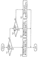
FIG. 1 illustrates the configuration of the
また、この例では、モータ3は、永久磁石モータにより構成されている。例えば、モータ3は、埋込磁石同期モータ(IPMSM)や表面磁石同期モータ(SPMSM)などによって構成されている。なお、モータ3は、ブラシレスモータによって構成されていてもよい。直流電源2は、例えば、リチウムイオン電池によって構成されていてもよい。
Further, in this example, the
この例では、モータ制御装置10は、インバータ11と、平滑キャパシタ12と、センサ20と、制御部30とを備えている。
In this example, the
〔インバータ〕
インバータ11は、スイッチング動作により直流電源2から供給された直流電力を三相の交流電力に変換して、その交流電力をモータ3に供給するように構成されている。具体的には、インバータ11は、3つのハイサイドスイッチング素子(第1,第2,第3ハイサイドスイッチング素子S1,S2,S3)と、3つのローサイドスイッチング素子(第1,第2,第3ローサイドスイッチング素子S4,S5,S6)とを有している。
[Inverter]
The
3つのハイサイドスイッチング素子S1〜S3は、モータ3の3つの入力端子にそれぞれ接続される3つの出力線(第1,第2,第3出力線LOu,LOv,LOw)と直流電源2の正極に接続される電源線LPとの間にそれぞれ接続されている。例えば、ハイサイドスイッチング素子S1〜S3は、電界効果トランジスタ(FET)や絶縁ゲートバイポーラトランジスタ(IGBT)などによって構成されている。また、ハイサイドスイッチング素子S1〜S3は、ワイドバンドギャップ半導体を用いて構成されたものであってもよい。
The three high-side switching elements S1 to S3 have three output lines (first, second, third output lines LOu, Lov, LOw) connected to three input terminals of the
3つのローサイドスイッチング素子S4〜S6は、3つの出力線LOu〜LOwと直流電源2の負極に接続される接地線LGとの間にそれぞれ接続されている。例えば、ローサイドスイッチング素子S4〜S6は、電界効果トランジスタ(FET)や絶縁ゲートバイポーラトランジスタ(IGBT)などによって構成されている。また、ローサイドスイッチング素子S4〜S6は、ワイドバンドギャップ半導体を用いて構成されたものであってもよい。
The three low-side switching elements S4 to S6 are connected between the three output lines LOu to LOw and the ground wire LG connected to the negative electrode of the
なお、この例では、6つのスイッチング素子S1〜S6のそれぞれに還流ダイオードが並列に接続されている。これらの還流ダイオードは、スイッチング素子S1〜S6に寄生する寄生ダイオードであってもよいし、スイッチング素子S1〜S6とは別体に構成されたダイオード素子であってもよい。 In this example, a freewheeling diode is connected in parallel to each of the six switching elements S1 to S6. These freewheeling diodes may be parasitic diodes parasitic on the switching elements S1 to S6, or may be diode elements configured separately from the switching elements S1 to S6.
〔平滑キャパシタ〕
平滑キャパシタ12は、電源線LPと接地線LGとの間に接続され、電源線LPに印加される電源電圧VPを平滑化するように構成されている。具体的には、平滑キャパシタ12は、電源電圧VPのリップルの低減やサージ電圧の吸収などを行うように構成されている。例えば、平滑キャパシタ12は、電解コンデンサやフィルムコンデンサによって構成されている。
[Smoothing capacitor]
The smoothing
〔センサ〕
センサ20は、インバータ11のスイッチング動作の制御に用いられる情報を検知するように構成されている。この例では、モータ制御装置10には、3つの出力線LOu〜LOwにそれぞれ対応する3つの電流センサ(第1,第2,第3電流センサ21u,21v,21w)や磁極位置センサ22などの各種センサが設けられている。
[Sensor]
The
3つの電流センサ21u〜21wは、モータ3に流れる3つの相電流(U相電流iuとV相電流ivとW相電流iw)をそれぞれ検知するように構成されている。例えば、電流センサ21u〜21wは、シャント抵抗によって構成されていている。
The three
磁極位置センサ22は、モータ3の磁極位置θeを検知するように構成されている。
The magnetic
〔制御部〕
制御部30は、センサ20により検知された情報や外部から入力された制御指令などに基づいてインバータ11のスイッチング動作を制御するように構成されている。例えば、制御部30は、CPUなどの演算処理部と、演算処理部を動作させるためのプログラムや情報などを記憶するメモリなどの記憶部と、スイッチング素子S1〜S6にゲート信号を供給してスイッチング素子S1〜S6のオンオフを制御するゲートドライブICなどの駆動回路とによって構成されている。
[Control unit]
The
この例では、制御部30には、電流センサ21u〜21wにより検知された相電流iu〜iwと、磁極位置センサ22により検知されたモータ3の磁極位置θeと、電源電圧VPと、モータ3の目標トルク(例えば電気車両のアクセルペダルの操作量に応じたトルク)を示すトルク指令Teとが入力される。
In this example, the
また、制御部30は、直流電源2とモータ3とインバータ11とセンサ20のうち少なくとも1つに対して異常判定を行う。この例では、制御部30は、直流電源2とモータ3とインバータ11とセンサ20の全部に対して異常判定を行う。なお、異常判定については、後で詳しく説明する。
Further, the
また、制御部30は、異常判定により異常があると判定されるまで通常制御を行う。通常制御では、制御部30は、センサ20により検知された情報に基づいてインバータ11のスイッチング動作を制御する。具体的には、制御部30は、モータ3のトルクがトルク指令Teに示された目標トルクとなるように電流センサ21u〜21wや磁極位置センサ22などの各種センサからの検知信号(具体的には3つの出力線LOu〜LOwをそれぞれ流れる相電流iu〜iwとモータ3の磁極位置θe)に基づいてインバータ11のスイッチング動作を制御する。
Further, the
この例では、制御部30は、通常制御において、モータ3の回転速度に応じてモータ3に対して弱め界磁制御を実施するように構成されている。具体的には、制御部30は、通常制御において、モータ3の回転速度が予め定められた高回転閾値を上回る場合に、モータ3に対して弱め界磁制御を実施し、モータ3の回転速度が高回転閾値を上回らない場合に、モータ3に対して弱め界磁制御を実施しないように構成されている。なお、高回転閾値は、モータ3の回転により発生する逆起電力が直流電源2の電源電圧と同等となるときのモータ3の回転速度よりも低い回転速度に設定されている。
In this example, the
なお、この例では、制御部30は、磁極位置センサ22により検知された磁極位置θeに基づいてモータ3の回転速度を取得するように構成されている。具体的には、制御部30は、磁極位置センサ22により検知された磁極位置θeを微分することによりモータ3の回転速度を算出する。
In this example, the
また、制御部30は、異常判定により異常があると判定されると、モータ3の動作状態に応じて三相短絡制御と全開放制御のいずれか一方を行う。三相短絡制御では、制御部30は、3つのハイサイドスイッチング素子S1〜S3からなるハイサイドスイッチング素子群および3つのローサイドスイッチング素子S4〜S6からなるローサイドスイッチング素子群のうち一方のスイッチング素子群をオン状態にするとともに他方のスイッチング素子群をオフ状態にする。全開放制御では、制御部30は、3つのハイサイドスイッチング素子S1〜S3からなるハイサイドスイッチング素子群および3つのローサイドスイッチング素子S4〜S6からなるローサイドスイッチング素子群の全部をオフ状態にする。
Further, when the abnormality determination determines that there is an abnormality, the
この例では、制御部30は、異常判定により異常があると判定されると、モータ3に対する弱め界磁制御の実施の有無およびモータ3の回転速度のうち少なくとも一方に応じて三相短絡制御と全開放制御のいずれか一方を行うように構成されている。具体的には、制御部30は、モータ3に対する弱め界磁制御が実施されている場合またはモータ3の回転速度が予め定められた回転速度閾値を上回る場合に、三相短絡制御を行い、モータ3に対する弱め界磁制御が実施されておらず且つモータ3の回転速度が回転速度閾値を上回らない場合に、全開放制御を行うように構成されている。なお、回転速度閾値は、高回転閾値(弱め界磁制御の実施の要否の判定基準となる回転速度)と同一の回転速度であってもよいし、高回転閾値と異なる回転速度であってもよい。
In this example, when the
また、制御部30は、異常判定により異常があると判定された後の期間(異常継続期間)において、モータ3に作用するトルクTetに応じて三相短絡制御と全開放制御のいずれか一方を行う。具体的には、制御部30は、異常継続期間において、三相短絡制御が行われている場合にモータ3に作用するトルクTetが予め定められた第1トルク閾値Tth1を下回ると、三相短絡制御を終了して全開放制御を開始する。また、制御部30は、異常継続期間において、全開放制御が行われている場合にモータ3に作用するトルクTetが予め定められた第2トルク閾値Tth2を上回ると、全開放制御を終了して三相短絡制御を開始する。なお、第1トルク閾値Tth1と第2トルク閾値Tth2については、後で詳しく説明する。
Further, the
なお、この例では、制御部30は、電流センサ21u〜21wにより検知された相電流iu〜iwと磁極位置センサ22により検知された磁極位置θeに基づいてモータ3に作用するトルクTetを取得(推定)するように構成されている。具体的には、制御部30は、電流センサ21u〜21wにより検知された相電流iu〜iwと磁極位置センサ22により検知された磁極位置θeに基づいてd軸電流idおよびq軸電流iqを導出し、そのd軸電流idおよびq軸電流iqを下記の式に代入することによってモータ3に作用するトルクTetを導出する。
In this example, the
![]()
![]()
上記の式において、“npole”はモータ3の極対数を示し、“φa”は電機子鎖交磁束を示し、“Ld”はd軸インダクタンスを示し、“Lq”はq軸インダクタンスを示している。
In the above equation, "npole" indicates the number of pole pairs of the
〔制御部の構成〕
図1に示すように、この例では、制御部30は、異常判定部31と、スイッチング制御部32と、動作制御部33とを有している。すなわち、異常判定部31とスイッチング制御部32と動作制御部33は、ソフトウェアにより実現されており、制御部30の機能の一部を構成している。
[Structure of control unit]
As shown in FIG. 1, in this example, the
〔異常判定部〕
異常判定部31は、直流電源2とモータ3とインバータ11とセンサ20の少なくとも1つに対して異常判定を行うように構成されている。この例では、異常判定部31は、直流電源2とモータ3とインバータ11とセンサ20との全部に対して異常判定を行う。なお、異常判定部31(制御部30)は、直流電源2とモータ3とインバータ11とセンサ20の異常を以下のように判定するものであってもよい。
[Abnormality judgment unit]
The
〈直流電源の異常判定〉
例えば、異常判定部31は、電源電圧VPを入力し、電源電圧VPに基づいて直流電源2の異常を判定する。具体的には、異常判定部31は、電源電圧VPが予め定められた電源電圧閾値を上回る場合に、直流電源2に異常があると判定する。
<Determination of DC power supply abnormality>
For example, the
〈モータおよびインバータの異常判定〉
また、異常判定部31は、電流センサ21u〜21wにより検知された相電流iu〜iwを入力し、相電流iu〜iwに基づいてモータ3およびインバータ11の異常を判定する。具体的には、異常判定部31は、3つの相電流iu〜iwの位相差が正常範囲(例えば120°±αの範囲、αは120°よりも小さい)を逸脱している場合に、モータ3およびインバータ11に異常があると判定する。
<Abnormality judgment of motor and inverter>
Further, the
〈センサの異常判定〉
また、異常判定部31は、センサ20(この例では電流センサ21u〜21wと磁極位置センサ22)の出力を入力し、センサ20の出力に基づいてセンサ20の異常を判定する。具体的には、異常判定部31は、センサ20の出力が最大レベル(または最小レベル)で一定となっている期間の長さが予め定められた正常期間長さよりも長い場合に、センサ20に異常があると判定する。なお、一般的に、センサ20に断線などの異常が発生した場合、そのセンサ20の出力は、最大レベル(または最小レベル)で一定となる。
<Sensor abnormality judgment>
Further, the
〈スイッチング素子の短絡異常の判定〉
また、この例では、異常判定部31は、3つのハイサイドスイッチング素子S1〜S3および3つのローサイドスイッチング素子S4〜S6の各々に対してそのスイッチング素子が常にオン状態となる短絡異常であるか否かを判定するように構成されている。なお、異常判定部31は、スイッチング素子S1〜S6の短絡異常を以下のように判定するものであってもよい。
<Judgment of short-circuit abnormality of switching element>
Further, in this example, whether or not the
例えば、異常判定部31は、3つの出力線LOu〜LOwにそれぞれ印加される3つの相電圧(U相電圧VuとV相電圧VvとW相電圧Vw)と電源電圧VPと接地電圧VGとを入力し、これらの3つの相電圧Vu〜Vwと電源電圧VPと接地電圧VGとに基づいてスイッチング素子S1〜S6の短絡異常を判定する。
For example, the
具体的には、異常判定部31は、第1ハイサイドスイッチング素子S1をオフ状態にすべき期間において電源電圧VPと第1ハイサイドスイッチング素子S1に対応するU相電圧Vuとの差が異常値(例えば第1ハイサイドスイッチング素子S1がオフ状態となっているときの電源電圧VPとU相電圧Vuとの差に相当する正常値よりも小さい値)である場合に、第1ハイサイドスイッチング素子S1が短絡異常であると判定し、第1ハイサイドスイッチング素子S1をオフ状態にすべき期間において電源電圧VPと第1ハイサイドスイッチング素子S1に対応するU相電圧Vuとの差が正常値である場合に、第1ハイサイドスイッチング素子S1が短絡異常ではないと判定する。なお、第2および第3ハイサイドスイッチング素子S2,S3についても同様である。
Specifically, in the
また、異常判定部31は、第1ローサイドスイッチング素子S4をオフ状態にすべき期間において第1ローサイドスイッチング素子S4に対応するU相電圧Vuと接地電圧VGとの差が異常値(例えば、第1ローサイドスイッチング素子S4がオフ状態となっているときのU相電圧Vuと接地電圧VGとの差に相当する正常値よりも小さい値)である場合に、第1ローサイドスイッチング素子S4が短絡異常であると判定し、第1ローサイドスイッチング素子S4をオフ状態にすべき期間において第1ローサイドスイッチング素子S4に対応するU相電圧Vuと接地電圧VGとの差が正常値である場合に、第1ローサイドスイッチング素子S4が短絡異常ではないと判定する。なお、第2および第3ローサイドスイッチング素子S5,S6についても同様である。
Further, in the
また、異常判定部31は、6つのスイッチング素子S1〜S6に対する短絡異常の判定結果に基づいてインバータ11の異常を判定する。具体的には、異常判定部31は、6つのスイッチング素子S1〜S6の中に短絡異常であると判定されたスイッチング素子がある場合に、インバータ11に異常があると判定する。
Further, the
〈スイッチング素子の開放異常の判定〉
また、この例では、異常判定部31は、3つのハイサイドスイッチング素子S1〜S3および3つのローサイドスイッチング素子S4〜S6の各々に対してそのスイッチング素子が常にオフ状態となる開放異常であるか否かを判定するように構成されている。なお、異常判定部31は、スイッチング素子S1〜S6の開放異常を以下のように判定するものであってもよい。
<Judgment of opening abnormality of switching element>
Further, in this example, whether or not the
例えば、異常判定部31は、3つの出力線LOu〜LOwにそれぞれ印加される3つの相電圧(U相電圧VuとV相電圧VvとW相電圧Vw)と電源電圧VPと接地電圧VGとを入力し、これらの3つの相電圧Vu〜Vwと電源電圧VPと接地電圧VGとに基づいてスイッチング素子S1〜S6の開放異常を判定する。
For example, the
具体的には、異常判定部31は、第1ハイサイドスイッチング素子S1をオン状態にすべき期間において電源電圧VPと第1ハイサイドスイッチング素子S1に対応するU相電圧Vuとの差が異常値(例えば第1ハイサイドスイッチング素子S1がオン状態となっているときの電源電圧VPとU相電圧Vuとの差に相当する正常値よりも大きい値)である場合に、第1ハイサイドスイッチング素子S1が開放異常であると判定し、第1ハイサイドスイッチング素子S1をオン状態にすべき期間において電源電圧VPと第1ハイサイドスイッチング素子S1に対応するU相電圧Vuとの差が正常値である場合に、第1ハイサイドスイッチング素子S1が開放異常ではないと判定する。なお、第2および第3ハイサイドスイッチング素子S2,S3についても同様である。
Specifically, in the
また、異常判定部31は、第1ローサイドスイッチング素子S4をオン状態にすべき期間において第1ローサイドスイッチング素子S4に対応するU相電圧Vuと接地電圧VGとの差が異常値(例えば、第1ローサイドスイッチング素子S4がオン状態となっているときのU相電圧Vuと接地電圧VGとの差に相当する正常値よりも大きい値)である場合に、第1ローサイドスイッチング素子S4が開放異常であると判定し、第1ローサイドスイッチング素子S4をオフ状態にすべき期間において第1ローサイドスイッチング素子S4に対応するU相電圧Vuと接地電圧VGとの差が正常値である場合に、第1ローサイドスイッチング素子S4が開放異常ではないと判定する。なお、第2および第3ローサイドスイッチング素子S5,S6についても同様である。
Further, in the
また、異常判定部31は、6つのスイッチング素子S1〜S6に対する開放異常の判定結果に基づいてインバータ11の異常を判定する。具体的には、異常判定部31は、6つのスイッチング素子S1〜S6の中に開放異常であると判定されたスイッチング素子がある場合に、インバータ11に異常があると判定する。
Further, the
〔スイッチング制御部〕
スイッチング制御部32は、通常制御と三相短絡制御と全開放制御とを行うように構成されている。また、スイッチング制御部32は、通常制御において、モータ3の回転速度に応じてモータ3に対して弱め界磁制御を実施するように構成されている。具体的には、スイッチング制御部32は、通常制御において、モータ3の回転速度が高回転閾値を上回る場合に、モータ3に対して弱め界磁制御を実施し、モータ3の回転速度が高回転閾値を上回らない場合に、モータ3に対して弱め界磁制御を実施しないように構成されている。
[Switching control unit]
The switching
〈スイッチング制御部の構成例〉
図2は、スイッチング制御部32の構成を例示している。スイッチング制御部32は、座標変換部301と、電流指令生成部302と、電流制御部303と、座標逆変換部304と、PWM信号生成部305と、弱め界磁制御部306とを有している。
<Configuration example of switching control unit>
FIG. 2 illustrates the configuration of the switching
座標変換部301は、電流センサ21u〜21wにより検知された相電流iu〜iwと磁極位置センサ22により検知された磁極位置θeとに基づいて、モータ3のd軸電流idおよびq軸電流iqを導出する。
The coordinate
電流指令生成部302は、トルク指令Teに基づいてd軸電流指令値id*およびq軸電流指令値iq*を導出する。具体的には、電流指令生成部302は、トルク指令Teに正弦値(sinθ)を乗算してd軸電流指令値id*を導出し、トルク指令Teに余弦値(cosθ)を乗算してq軸電流指令値iq*を導出する。
The current
電流制御部303は、座標変換部301により導出されたd軸電流idおよびq軸電流iqと電流指令生成部302により導出されたd軸電流指令値id*およびq軸電流指令値iq*とに基づいて、d軸電圧指令値Vd*およびq軸電圧指令値Vq*を導出する。具体的には、電流制御部303は、d軸電流idとd軸電流指令値id*との差およびq軸電流iqとq軸電流指令値iq*との差がそれぞれ小さくなるように、d軸電圧指令値Vd*およびq軸電圧指令値Vq*を導出する。
The
座標逆変換部304は、電流制御部303により導出されたd軸電圧指令値Vd*およびq軸電圧指令値Vq*と磁極位置センサ22により検知された磁極位置θeとに基づいて、U相電圧指令値Vu*とV相電圧指令値Vv*とW相電圧指令値Vw*を導出する。
The coordinate
PWM信号生成部305は、座標逆変換部304により導出されたU相電圧指令値Vu*とV相電圧指令値Vv*とW相電圧指令値Vw*に基づいて、6つのスイッチング素子S1〜S6にそれぞれ供給される6つのゲート信号を生成する。具体的には、PWM信号生成部305は、U相電圧指令値Vu*とV相電圧指令値Vv*とW相電圧指令値Vw*に基づいて6つのゲート信号をPWM制御する。
The PWM signal generation unit 305 has six switching elements S1 to S6 based on the U-phase voltage command value Vu *, the V-phase voltage command value Vv *, and the W-phase voltage command value Vw * derived by the coordinate
弱め界磁制御部306は、モータ3の回転速度に基づいて弱め界磁制御の実施の要否を判定する。具体的には、弱め界磁制御部306は、モータ3の回転速度が高回転閾値を上回る場合に弱め界磁制御の実施が必要であると判定し、モータ3の回転速度が高回転閾値を上回らない場合に弱め界磁制御の実施が不要であると判定する。そして、弱め界磁制御を実施する場合、弱め界磁制御部306は、d軸電流指令値id*が負となるように電流指令生成部302の動作を制御する。一方、弱め界磁制御を実施しない場合、弱め界磁制御部306は、電流指令生成部302の制御を解除する。
The field
なお、この例では、スイッチング制御部32(具体的には弱め界磁制御部306)は、磁極位置センサ22により検知された磁極位置θeに基づいてモータ3の回転速度を取得するように構成されている。
In this example, the switching control unit 32 (specifically, the field weakening control unit 306) is configured to acquire the rotation speed of the
〔動作制御部〕
動作制御部33は、異常判定部31による異常判定の結果に応じてスイッチング制御部32の動作を制御するように構成されている。なお、動作制御部33の動作は、異常判定により異常があると判定されるまで行われる動作(通常動作)と、異常判定により異常があると判定された場合に行われる動作(異常発生対応動作)と、異常判定により異常があると判定された後の期間(異常継続期間)に行われる動作(異常継続対応動作)とに大別される。
[Operation control unit]
The
〈通常動作〉
動作制御部33は、異常判定部31により異常があると判定されるまで、スイッチング制御部32に通常制御を行わせるように構成されている。
<Normal operation>
The
〈異常発生対応動作〉
また、動作制御部33は、異常判定部31により異常があると判定されると、モータ3の動作状態に応じて三相短絡制御と全開放制御のいずれか一方をスイッチング制御部32に行わせるように構成されている。この例では、動作制御部33は、異常判定部31により異常があると判定されると、モータ3に対する弱め界磁制御の実施の有無およびモータ3の回転速度のうち少なくとも一方に応じて三相短絡制御と全開放制御のいずれか一方をスイッチング制御部32に行わせるように構成されている。具体的には、動作制御部33は、モータ3に対する弱め界磁制御が実施されている場合またはモータ3の回転速度が予め定められた回転速度閾値を上回る場合に、スイッチング制御部32に三相短絡制御を行わせ、モータ3に対する弱め界磁制御が実施されておらず且つモータ3の回転速度が回転速度閾値を上回らない場合に、スイッチング制御部32に全開放制御を行わせるように構成されている。
<Operation for responding to abnormal occurrences>
Further, when the
〈異常継続対応動作〉
また、動作制御部33は、異常判定部31により異常があると判定された後の期間(異常継続期間)において、モータ3に作用するトルクTetに応じて三相短絡制御と全開放制御のいずれか一方をスイッチング制御部32に行わせるように構成されている。具体的には、動作制御部33は、異常継続期間において、三相短絡制御が行われている場合にモータ3に作用するトルクTetが第1トルク閾値Tth1を下回ると、スイッチング制御部32が三相短絡制御を終了して全開放制御を開始するようにスイッチング制御部32の動作を制御する。また、動作制御部33は、異常継続期間において、全開放制御が行われている場合にモータ3に作用するトルクTetが第2トルク閾値Tth2を上回ると、スイッチング制御部32が全開放制御を終了して三相短絡制御を開始するようにスイッチング制御部32の動作を制御する。
<Operation for continuous abnormalities>
Further, in the period after the
なお、この例では、動作制御部33は、磁極位置センサ22により検知された磁極位置θeに基づいてモータ3の回転速度を取得するように構成されている。また、動作制御部33は、電流センサ21u〜21wにより検知された相電流iu〜iwと磁極位置センサ22により検知された磁極位置θeに基づいてモータ3に作用するトルクTetを取得(推定)するように構成されている。例えば、動作制御部33は、スイッチング制御部32の座標変換部301(図2参照)により導出されたd軸電流idおよびq軸電流iqに基づいてモータ3に作用するトルクTetを取得する。
In this example, the
〔三相短絡制御における挙動〕
次に、図3を参照して三相短絡制御における挙動について説明する。図3は、三相短絡制御が行われている場合においてモータ3に作用するトルクTetとモータ3の回転速度との関係を例示している。三相短絡制御が行われている場合、モータ3には回生トルクが作用する。この回生トルクは、負の値を有するトルク(すなわちモータ3の回転方向に対して逆方向に作用するトルク)であり、図3に示すように、モータ3の回転速度が低くなるに連れてモータ3に作用するトルクTet(負の値を有する回生トルク)の絶対値が次第に大きくなる傾向にある。そのため、三相短絡制御が行われている場合にモータ3の回転速度が低下する(例えば電気車両の車速が低下する)と、モータ3に作用する回生トルク(負の値を有するトルクTet)によりモータ3の回転速度が急激に低下してしまう可能性がある。
[Behavior in three-phase short circuit control]
Next, the behavior in the three-phase short-circuit control will be described with reference to FIG. FIG. 3 illustrates the relationship between the torque Tet acting on the
図3の例では、モータ3の回転速度が第1回転速度R1を下回ると、モータ3の回転速度の低下に対するモータ3に作用するトルクTet(負の値を有する回生トルク)の絶対値の増加の割合(回生トルクの増加率)が高くなっている。そして、この例では、三相短絡制御から全開放制御への切り換えの判定基準となる第1トルク閾値Tth1は、モータ3の回転速度が第1回転速度R1であるとき(すなわちモータ3に作用する回生トルクの増加率が高くなるとみなせるとき)にモータ3に作用するトルクの値に設定されている。
In the example of FIG. 3, when the rotation speed of the
〔全開放制御における挙動〕
次に、図4を参照して全開放制御における挙動について説明する。図4は、全開放制御が行われている場合においてモータ3に作用するトルクTetとモータ3の回転速度との関係を例示している。全開放制御が行われている場合、モータ3の回転速度が高くなるに連れてモータ3の誘起電圧が高くなる傾向にある。そのため、全開放制御が行われている場合にモータ3の回転速度が上昇する(例えば下り坂などにより電気車両の車速が上昇する)と、モータ3からインバータ11を経由して直流電源2側に回生される電力により直流電源2とインバータ11とを接続する電力線(電源線LPと接地線LG)が過電圧(例えば法規制電圧を上回る電圧)となる可能性がある。
[Behavior in full open control]
Next, the behavior in the fully open control will be described with reference to FIG. FIG. 4 illustrates the relationship between the torque Tet acting on the
なお、モータ3の回転速度の上昇に伴ってモータ3の誘起電圧が高くなりモータ3の誘起電圧が直流電源2の電圧を上回ると、図4に示すように、モータ3に作用するトルクTetが大きくなる。図4の例では、モータ3の回転速度が第2回転速度R2を上回ると、モータ3に作用するトルクTetが大きくなっている。そして、この例では、全開放制御から三相短絡制御への切り換えの判定基準となる第2トルク閾値Tth2は、モータ3の回転速度が第2回転速度であるとき(すなわちモータ3の誘起電圧が直流電源2の電圧を上回るとみなせるとき)にモータ3に作用するトルクの値に設定されている。
When the induced voltage of the
また、図4より、モータ3の回転速度が第2回転速度R2を上回ると、モータ3に作用するトルクTetが大きく変動する。その結果、もし、全開放制御が行われたまま、下り坂などにより電気車両の車速が上昇し、モータ3の回転速度が上昇すると、トルクTetの変動に起因した振動が電気車両に発生する。したがって、振動を避けるために、乗員にとってほとんど振動を感じない第2トルク閾値Tth2を設定し、この第2トルク閾値Tth2を超えるトルクTetが発生すれば、動作制御部33は全開放制御から三相短絡制御へ切り換える。これにより、モータ3のトルクTetと回転速度との関係は図3のようになり、下り坂が継続してモータ3の回転速度がさらに上昇しても、トルクTetの変動はほとんど起こらず、振動を抑制できる。
Further, as shown in FIG. 4, when the rotation speed of the
なお、図4において、もしモータ3の第2回転速度R2を閾値として、回転速度に基づいて動作制御部33が全開放制御から三相短絡制御へ切り換えると、回転速度の検出誤差により、第2トルク閾値Tth2を超えてから切り換える場合がある。したがって、電気車両の振動を乗員がほとんど感じないように抑制するためには、モータ3に作用するトルクTetに応じて、全開放制御と三相短絡制御のいずれか一方を行うようにすればよい。
In FIG. 4, if the
〔弱め界磁制御の切り換え動作〕
次に、図5を参照して、スイッチング制御部32の通常制御における弱め界磁制御の切り換え動作について説明する。この切り換え動作は、異常判定部31により異常があると判定されるまで繰り返し行われる。
[Switching operation of field weakening control]
Next, with reference to FIG. 5, the switching operation of the field weakening control in the normal control of the switching
〈ステップS11〉
まず、スイッチング制御部32(具体的には弱め界磁制御部306)は、モータ3の回転速度を取得する。この例では、スイッチング制御部32は、磁極位置センサ22により検知された磁極位置θeに基づいてモータ3の回転速度を算出する。そして、スイッチング制御部32は、モータ3の回転速度が高回転閾値を上回るか否かを判定する。モータ3の回転速度が高回転閾値を上回る場合にはステップS12へ進み、そうでない場合にはステップS13へ進む。
<Step S11>
First, the switching control unit 32 (specifically, the field weakening control unit 306) acquires the rotation speed of the
〈ステップS12〉
モータ3の回転速度が高回転閾値を上回る場合、スイッチング制御部32は、モータ3に対して弱め界磁制御を実施する。例えば、スイッチング制御部32は、電流センサ21u〜21wにより検知された相電流iu〜iwと磁極位置センサ22により検知された磁極位置θeとに基づいて、モータ3のd軸電流が負となるように、6つのスイッチング素子S1〜S6にそれぞれ供給される6つのゲート信号をPWM制御してインバータ11のスイッチング動作を制御する。このように負のd軸電流を流すことにより、電機子反作用による減磁効果を利用してd軸方向の磁束を減少させることができる。これにより、モータ3の回転により発生する逆起電力を低減することができるので、モータ3の回転速度を上昇させることができる。
<Step S12>
When the rotation speed of the
〈ステップS13〉
一方、モータ3の回転速度が高回転閾値を上回らない場合、スイッチング制御部32は、モータ3に対する弱め界磁制御を解除する。例えば、スイッチング制御部32は、モータ3に対して最大トルク電流制御などの他の同期制御が実施されるように、6つのスイッチング素子S1〜S6にそれぞれ供給される6つのゲート信号をPWM制御してインバータ11のスイッチング動作を制御する。
<Step S13>
On the other hand, when the rotation speed of the
〔異常発生対応動作〕
次に、図6を参照して、動作制御部33の異常発生対応動作について説明する。この異常発生対応動作は、異常判定部31により異常があると判定されたときに行われる。
[Operation for responding to abnormal occurrence]
Next, with reference to FIG. 6, the operation for dealing with the occurrence of an abnormality in the
〈ステップS21〉
まず、動作制御部33は、モータ3に対する弱め界磁制御が実施されているか否かを判定する。例えば、スイッチング制御部32(具体的には弱め界磁制御部306)は、モータ3に対する弱め界磁制御を実施している場合に、弱め界磁制御を実施していることを示すフラグ(以下「弱め界磁フラグ」と記載)を立てた状態にし、モータ3に対する弱め界磁制御を解除すると弱め界磁フラグを降ろした状態にする。そして、動作制御部33は、弱め界磁フラグに基づいてモータ3に対する弱め界磁制御の実施の有無を判定する。モータ3に対する弱め界磁制御が実施されていない場合(例えば弱め界磁フラグが降ろされている場合)にはステップS23へ進み、そうでない場合にはステップS22へ進む。
<Step S21>
First, the
〈ステップS22〉
次に、動作制御部33は、モータ3の回転速度を取得する。この例では、動作制御部33は、磁極位置センサ22により検知された磁極位置θeに基づいてモータ3の回転速度を算出する。そして、動作制御部33は、モータ3の回転速度が回転速度閾値を上回るか否かを判定する。モータ3の回転速度が回転速度閾値を上回らない場合にはステップS23へ進み、そうでない場合にはステップS24へ進む。なお、回転速度閾値は、例えば図3に基づいて、モータ3に作用するトルクTetの絶対値の増加の割合が高くならない回転速度、すなわち、第1回転速度R1であってもよい。
<Step S22>
Next, the
〈ステップS23〉
モータ3に対する弱め界磁制御が実施されていない場合、または、モータ3に対する弱め界磁制御が実施されており且つモータ3の回転速度が回転速度閾値を上回らない場合、動作制御部33は、三相短絡制御と全開放制御のうち全開放制御が行われるようにスイッチング制御部32を制御する。これにより、3つのハイサイドスイッチング素子S1〜S3および3つのローサイドスイッチング素子S4〜S6の全部がオフ状態となり、インバータ11のスイッチング動作が停止する。
<Step S23>
When the field weakening control for the
〈ステップS24〉
一方、モータ3に対する弱め界磁制御が実施されており且つモータ3の回転速度が回転速度閾値を上回る場合、動作制御部33は、三相短絡制御と全開放制御のうち三相短絡制御が行われるようにスイッチング制御部32を制御する。これにより、3つのハイサイドスイッチング素子S1〜S3からなるハイサイドスイッチング素子群および3つのローサイドスイッチング素子S4〜S6からなるローサイドスイッチング素子群のうち一方のスイッチング素子群がオン状態となるとともに他方のスイッチング素子群がオフ状態となり、インバータ11のスイッチング動作が停止する。
<Step S24>
On the other hand, when the field weakening control for the
〔三相短絡制御と全開放制御の特徴〕
異常判定部31により異常があると判定された場合(例えば電気車両の走行中に直流電源2が失陥するという異常が発生した場合)に全開放制御が行われると、モータ3のステータコイルに蓄積された電力がスイッチング素子S1〜S6に逆並列接続された還流ダイオードを経由して平滑キャパシタ12に供給されて平滑キャパシタ12が充電され、その結果、平滑キャパシタ12の端子間電圧が上昇することになる。この平滑キャパシタ12の端子間電圧の上昇は、モータ3の回転速度が高くなるほど大きくなる傾向にある。すなわち、異常判定部31により異常があると判定されて全開放制御が行われている場合、モータ3の回転速度が高くなるほど、直流電源2とインバータ11とを接続する電力線(電源線LPおよび接地線LG)に印加される電圧が高くなり、直流電源2とインバータ11とを接続する電力線が過電圧となる可能性が高くなる。
[Characteristics of three-phase short-circuit control and full-open control]
When the
一方、異常判定部31により異常があると判定された場合(例えば電気車両の走行中に直流電源2が失陥するという異常が発生した場合)に三相短絡制御が行われると、3つの出力線LOu〜LOwが互いに小さい抵抗(スイッチング素子S1〜S6のオン抵抗)を経由して接続された状態となり、その結果、3つの出力線LOu〜LOwをそれぞれ流れる3つの相電流iu〜iwが瞬時的に増加することになる。この相電流iu〜iwの瞬時的な増加は、モータ3の回転速度が低くなるほど大きくなる傾向にある。
On the other hand, when the
したがって、異常判定部31により異常があると判定されたときのモータ3の回転速度が比較的に高い場合に三相短絡制御を行う一方で、異常判定部31により異常があると判定されたときのモータ3の回転速度が比較的に低い場合に全開放制御を行うことにより、直流電源2とインバータ11とを接続する電力線(電源線LPおよび接地線LG)の過電圧と相電流iu〜iwの瞬時的な増加の両方を効果的に抑制することができる。
Therefore, when the three-phase short-circuit control is performed when the rotation speed of the
〔異常継続対応動作〕
次に、図7を参照して、動作制御部33の異常継続対応動作について説明する。この異常継続対応動作は、異常判定部31により異常があると判定された後の期間(異常継続期間)に繰り返し行われる。
[Operation for continuous abnormalities]
Next, with reference to FIG. 7, the operation for dealing with abnormal continuation of the
〈ステップS25〉
まず、動作制御部33は、スイッチング制御部32において三相短絡制御が行われているか否かを判定する。スイッチング制御部32において三相短絡制御が行われている場合にはステップS26へ進み、そうでない場合にはステップS28へ進む。
<Step S25>
First, the
〈ステップS26〉
三相短絡制御が行われている場合、動作制御部33は、モータ3に作用するトルクTetが第1トルク閾値Tth1を下回るか否かを判定する。モータ3に作用するトルクTetが第1トルク閾値Tth1を下回る場合にはステップS27へ進む。
<Step S26>
When the three-phase short circuit control is performed, the
〈ステップS27〉
三相短絡制御が行われている場合にモータ3に作用するトルクTetが第1トルク閾値Tth1を下回ると、動作制御部33は、スイッチング制御部32が三相短絡制御を終了して全開放制御を開始するようにスイッチング制御部32を制御する。
<Step S27>
When the torque Tet acting on the
〈ステップS28〉
一方、スイッチング制御部32において三相短絡制御が行われていない場合(すなわちスイッチング制御部32において全開放制御が行われている場合)、動作制御部33は、モータ3に作用するトルクTetが第2トルク閾値Tth2を上回るか否かを判定する。モータ3に作用するトルクTetが第2トルク閾値Tth2を上回る場合にはステップS29へ進む。
<Step S28>
On the other hand, when the three-phase short-circuit control is not performed in the switching control unit 32 (that is, when the full-open control is performed in the switching control unit 32), the
〈ステップS29〉
全開放制御が行われている場合にモータ3に作用するトルクTetが第2トルク閾値Tth2を上回ると、動作制御部33は、スイッチング制御部32が全開放制御を終了して三相短絡制御を開始するようにスイッチング制御部32を制御する。
<Step S29>
When the torque Tet acting on the
〔実施形態1による効果〕
以上のように、異常判定により異常があると判定された後の異常継続期間においてモータ3に作用するトルクTetに応じて三相短絡制御と全開放制御のいずれか一方を行うことにより、モータ3の急減速および直流電源2とインバータ11とを接続する電力線の過電圧の両方を効果的に抑制することができる。
[Effect of Embodiment 1]
As described above, by performing either the three-phase short-circuit control or the fully open control according to the torque Tet acting on the
また、電流センサ21u〜21wにより検知された相電流iu〜iwと磁極位置センサ22により検知された磁極位置θeとに基づいてモータ3に作用するトルクTetを取得(推定)することにより、モータ3に作用するトルクを検知するトルクセンサ(図示を省略)を別途設ける必要がなくなる。
Further, by acquiring (estimating) the torque Tet acting on the
また、異常判定により異常があると判定された場合に、モータ3の動作状態(具体的にはモータ3に対する弱め界磁制御の実施の有無およびモータ3の回転速度のうち少なくとも一方)に応じて三相短絡制御と全開放制御のいずれか一方を行うことにより、三相短絡制御と全開放制御のうちモータ3の動作状態に応じた制御を適切に行うことができる。
Further, when it is determined by the abnormality determination that there is an abnormality, the three-phase phase is determined according to the operating state of the motor 3 (specifically, whether or not the field weakening control is performed on the
また、磁極位置センサ22により検知された磁極位置θeに基づいてモータ3の回転速度を取得(算出)することにより、モータ3の回転速度を検知する回転速度センサ(図示を省略)を省略することができる。
Further, the rotation speed sensor (not shown) that detects the rotation speed of the
また、直流電源2とモータ3とインバータ11とセンサ20との全部に対して異常判定を行うことにより、直流電源2に異常が発生した場合だけでなく、直流電源2とモータ3とインバータ11とセンサ20の少なくとも1つに異常が発生した場合にモータ3の動作状態に応じて三相短絡制御と全開放制御とを選択的に行うことができる。これにより、直流電源2の異常による電力線(電源線LPと接地線LG)の過電圧だけでなく、直流電源2やモータ3やインバータ11やセンサ20の異常による電力線の過電圧を抑制することができる。
Further, by performing abnormality determination on all of the
(実施形態1の変形例)
なお、図6に示した動作制御部33の異常発生対応動作においてステップS22が省略されていてもよい。すなわち、動作制御部33は、異常判定部31により異常があると判定された場合に、モータ3に対する弱め界磁制御の実施の有無に応じて、三相短絡制御と全開放制御のいずれか一方をスイッチング制御部32に行わせるように構成されていてもよい。具体的には、動作制御部33は、モータ3に対する弱め界磁制御が実施されている場合に、三相短絡制御をスイッチング制御部32に行わせ、モータ3に対する弱め界磁制御が実施されていない場合に、全開放制御をスイッチング制御部32に行わせるように構成されていてもよい。
(Variation example of Embodiment 1)
Note that step S22 may be omitted in the operation for responding to the occurrence of an abnormality in the
また、図6に示した動作制御部33の異常発生対応動作においてステップS21が省略されていてもよい。すなわち、動作制御部33は、異常判定部31により異常があると判定された場合に、モータ3の回転速度に応じて、三相短絡制御と全開放制御のいずれか一方をスイッチング制御部32に行わせるように構成されていてもよい。具体的には、動作制御部33は、モータ3の回転速度が予め定められた回転速度閾値を上回る場合に、三相短絡制御をスイッチング制御部32に行わせ、モータ3の回転速度が回転速度閾値を上回らない場合に、全開放制御をスイッチング制御部32に行わせるように構成されていてもよい。
Further, step S21 may be omitted in the operation for responding to the occurrence of an abnormality in the
(実施形態2)
図8は、実施形態2によるモータ制御装置10の構成を例示している。実施形態2によるモータ制御装置10は、実施形態1によるモータ制御装置10と比べて、制御部30の構成が異なっている。実施形態2によるモータ制御装置10のその他の構成は、実施形態1によるモータ制御装置10の構成と同様となっている。
(Embodiment 2)
FIG. 8 illustrates the configuration of the
図8に示すように、実施形態2では、異常判定部31は、スイッチング制御部32および動作制御部33とは別体のハードウェアにより構成されている。そして、異常判定部31は、直流電源2とモータ3とインバータ11とセンサ20のうち少なくとも1つに対して異常判定を行い、異常判定において異常があると判定すると異常検知信号S31を動作制御部33に出力する。動作制御部33は、異常判定部31により異常検知信号S31が出力されるまで、スイッチング制御部32に通常制御を行わせる。また、動作制御部33は、異常判定部31により異常検知信号S31が出力されると、モータ3の動作状態に応じて三相短絡制御と全開放制御のいずれか一方をスイッチング制御部32に行わせる。そして、動作制御部33は、動作制御部33は、異常判定部31により異常検知信号S31が出力された後の期間(異常継続期間)において、モータ3に作用するトルクTetに応じて三相短絡制御と全開放制御のいずれか一方をスイッチング制御部32に行わせる。
As shown in FIG. 8, in the second embodiment, the
なお、実施形態2における動作制御部33の通常動作(異常検知信号S31が出力されるまで行われる動作)と異常発生対応動作(異常検知信号S31が出力された場合に行われる動作)と異常継続対応動作(異常検知信号S31が出力された後の期間に行われる動作)は、実施形態1における動作制御部33の通常動作と異常発生対応動作と異常継続対応動作とそれぞれ同様となっている。
The normal operation of the
また、図8に示すように、実施形態2では、動作制御部33は、スイッチング制御部32とは別体のハードウェアにより構成され、通常制御と三相短絡制御と全開放制御のいずれか1つを行わせるための制御信号S33をスイッチング制御部32に出力する。スイッチング制御部32は、動作制御部33により出力された制御信号S33に応答して通常制御と三相短絡制御と全開放制御のいずれか1つを行う。
Further, as shown in FIG. 8, in the second embodiment, the
なお、実施形態2では、スイッチング制御部32は、例えば、CPUなどの演算処理部と、演算処理部を動作させるためのプログラムや情報などを記憶するメモリなどの記憶部と、スイッチング素子S1〜S6にゲート信号を供給してスイッチング素子S1〜S6のオンオフを制御するゲートドライブICなどの駆動回路とによって構成されている。そして、実施形態2におけるスイッチング制御部32の動作は、実施形態1におけるスイッチング制御部32の動作と同様となっている。
In the second embodiment, the switching
〔実施形態2による効果〕
以上のように、異常判定部31をハードウェアによって構成することにより、異常判定部31をソフトウェアによって構成する場合よりも、異常判定部31における異常判定を迅速に行うことができる。
[Effect of Embodiment 2]
As described above, by configuring the
また、動作制御部33をハードウェアによって構成することにより、動作制御部33をソフトウェアによって構成する場合よりも、動作制御部33によるスイッチング制御部32の制御を迅速に行うことができる。
Further, by configuring the
なお、実施形態2において、異常判定部31と動作制御部33とが一体に形成されていてもよい。すなわち、異常判定部31と動作制御部33とが1つのハードウェアによって構成されていてもよい。
In the second embodiment, the
以上、実施形態1、2の説明では、制御部30(スイッチング制御部32と動作制御部33)が磁極位置センサ22により検知された磁極位置θeに基づいてモータ3の回転速度を取得する場合を例に挙げたが、モータ3の回転速度を検知する回転速度センサ(図示を省略)がモータ制御装置10に設けられていてもよい。そして、制御部30(スイッチング制御部32と動作制御部33)は、回転速度センサにより検知された回転速度を入力することでモータ3の回転速度を取得するように構成されていてもよい。
In the description of the first and second embodiments, the case where the control unit 30 (switching
また、実施形態1、2の説明では、制御部30(動作制御部33)が電流センサ21u〜21wにより検知された相電流iu〜iwと磁極位置センサ22により検知された磁極位置θeとに基づいてモータ3に作用するトルクTetを取得する場合を例に挙げたが、モータ3に作用するトルクを検知するトルクセンサ(図示を省略)がモータ制御装置10に設けられていてもよい。そして、制御部30(動作制御部33)は、トルクセンサにより検知されたトルクを入力することでモータ3に作用するトルクTetを取得するように構成されていてもよい。
Further, in the description of the first and second embodiments, the control unit 30 (operation control unit 33) is based on the phase currents iu to iw detected by the
また、実施形態1、2および変形例を適宜組み合わせて実施してもよい。以上の実施形態および変形例は、本質的に好ましい例示であって、この発明、その適用物、あるいはその用途の範囲を制限することを意図するものではない。 Further, the first and second embodiments and the modified examples may be combined as appropriate. The above embodiments and modifications are essentially preferred examples and are not intended to limit the scope of the invention, its applications, or its uses.
(実施形態3)
図9は、実施形態3によるモータ制御装置40の構成を例示している。実施形態3によるモータ制御装置40は、実施形態1によるモータ制御装置10の制御部30を制御部50で置き換えて構成されている。実施形態3によるモータ制御装置40のその他の構成は、実施形態1によるモータ制御装置10の構成と同様となっている。
(Embodiment 3)
FIG. 9 illustrates the configuration of the
〔制御部〕
制御部50は、センサ20により検知された情報や外部から入力された制御指令などに基づいてインバータ11のスイッチング動作を制御するように構成されている。例えば、制御部50は、CPUなどの演算処理部と、演算処理部を動作させるためのプログラムや情報などを記憶するメモリなどの記憶部と、スイッチング素子S1〜S6にゲート信号を供給してスイッチング素子S1〜S6のオンオフを制御するゲートドライブICなどの駆動回路とによって構成されている。
[Control unit]
The
この例では、制御部50には、電流センサ21u〜21wにより検知された相電流iu〜iwと、磁極位置センサ22により検知されたモータ3の磁極位置θeと、電源電圧VPと、モータ3の目標トルク(例えば電気車両のアクセルペダルの操作量に応じたトルク)を示すトルク指令Teとが入力される。
In this example, the
また、この例では、制御部50は、異常判定部51と、通常制御部52と、異常制御部53とを有している。すなわち、異常判定部51と通常制御部52と異常制御部53は、ソフトウェアにより実現されており、制御部50の機能の一部を構成している。
Further, in this example, the
〔異常判定部〕
異常判定部51は、直流電源2とモータ3とインバータ11とセンサ20の少なくとも1つに対して異常判定を行うように構成されている。この例では、異常判定部51は、直流電源2とモータ3とインバータ11とセンサ20との全部に対して異常判定を行う。なお、異常判定部51は、直流電源2とモータ3とインバータ11とセンサ20の異常を、実施形態1によるモータ制御装置10の異常判定部31と同様にして判定してもよい。
[Abnormality judgment unit]
The
〔通常制御部〕
通常制御部52は、異常判定部51により直流電源2とモータ3とインバータ11とセンサ20のうち少なくとも1つが異常であると判定されるまで、センサ20により検知された情報に基づいてインバータ11のスイッチング動作を制御する。具体的には、通常制御部52は、モータ3のトルクがトルク指令Teに示された目標トルクとなるように電流センサ21u〜21wや磁極位置センサ22などの各種センサからの検知信号(具体的には3つの出力線LOu〜LOwをそれぞれ流れる相電流iu〜iwとモータ3の磁極位置θe)に基づいてインバータ11のスイッチング動作を制御する。
[Normal control unit]
The
この例では、通常制御部52は、図5で説明した実施形態1の制御部30による弱め界磁制御動作と同様にして、モータ3の回転速度に応じてモータ3に対して弱め界磁制御を実施するように構成されている。
In this example, the
〔異常制御部〕
異常制御部53は、異常判定部51により直流電源2とモータ3とインバータ11とセンサ20のうち少なくとも1つが異常であると判定されると、モータ3の動作状態に応じて三相短絡制御と全開放制御のいずれか一方を選択して行う。三相短絡制御では、異常制御部53は、3つのハイサイドスイッチング素子S1〜S3からなるハイサイドスイッチング素子群および3つのローサイドスイッチング素子S4〜S6からなるローサイドスイッチング素子群のうち一方のスイッチング素子群をオン状態にするとともに他方のスイッチング素子群をオフ状態にする。全開放制御では、異常制御部53は、3つのハイサイドスイッチング素子S1〜S3からなるハイサイドスイッチング素子群および3つのローサイドスイッチング素子S4〜S6からなるローサイドスイッチング素子群の全部をオフ状態にする。
[Abnormality control unit]
When the
この例では、異常制御部53は、図6で説明した実施形態1の制御部30による異常発生対応動作と同様にして、通常制御部52によるモータ3に対する弱め界磁制御の実施の有無およびモータ3の回転速度のうち少なくとも一方に応じて、三相短絡制御と全開放制御のいずれか一方を選択して行うように構成されている。
In this example, the
三相短絡制御と全開放制御の特徴については、実施形態1で説明したとおりである。異常判定部51により異常があると判定されたときのモータ3の回転速度が比較的に高い場合に三相短絡制御を行う一方で、異常判定部51により異常があると判定されたときのモータ3の回転速度が比較的に低い場合に全開放制御を行うことにより、平滑キャパシタ12の端子間電圧の上昇と相電流iu〜iwの瞬時的な増加の両方を効果的に抑制することができる。
The features of the three-phase short-circuit control and the fully open control are as described in the first embodiment. Three-phase short-circuit control is performed when the rotation speed of the
〔三相短絡制御の詳細〕
次に、図10を参照して、異常制御部53による三相短絡制御の詳細について説明する。
[Details of three-phase short circuit control]
Next, the details of the three-phase short-circuit control by the
〈ステップS31〉
まず、異常制御部53は、異常判定部51による異常判定の結果に基づいて、6つのスイッチング素子(3つのハイサイドスイッチング素子S1〜S3および3つのローサイドスイッチング素子S4〜S6)の中に異常判定部31により短絡異常であると判定されたスイッチング素子があるか否かを判定する。6つのスイッチング素子S1〜S6の中に短絡異常であると判定されたスイッチング素子がある場合には、ステップS32へ進み、そうでない場合には、ステップS33へ進む。
<Step S31>
First, the
〈ステップS32〉
6つのスイッチング素子S1〜S6の中に短絡異常であると判定されたスイッチング素子がある場合、異常制御部53は、3つのハイサイドスイッチング素子S1〜S3からなるハイサイドスイッチング素子群および3つのローサイドスイッチング素子S4〜S6からなるローサイドスイッチング素子群のうち異常判定部51により短絡異常であると判定されたスイッチング素子を含むスイッチング素子群をオン状態にする。例えば、異常判定部51により第1ハイサイドスイッチング素子S1が短絡異常であると判定された場合、異常制御部53は、3つのハイサイドスイッチング素子S1〜S3がオン状態となるとともに3つのローサイドスイッチング素子S4〜S6がオフ状態となるように、6つのスイッチング素子S1〜S6に供給されるゲート信号を制御する。
<Step S32>
When there is a switching element determined to be a short-circuit abnormality among the six switching elements S1 to S6, the
〈ステップS33〉
一方、6つのスイッチング素子S1〜S6の中に短絡異常であると判定されたスイッチング素子がない場合、異常制御部53は、異常判定部51による異常判定の結果に基づいて、6つのスイッチング素子(3つのハイサイドスイッチング素子S1〜S3および3つのローサイドスイッチング素子S4〜S6)の中に異常判定部51により開放異常であると判定されたスイッチング素子があるか否かを判定する。6つのスイッチング素子S1〜S6の中に開放異常であると判定されたスイッチング素子がある場合には、ステップS34へ進み、そうでない場合には、ステップS35へ進む。
<Step S33>
On the other hand, when there is no switching element determined to be a short-circuit abnormality among the six switching elements S1 to S6, the
〈ステップS34〉
6つのスイッチング素子S1〜S6の中に開放異常であると判定されたスイッチング素子がある場合、異常制御部53は、3つのハイサイドスイッチング素子S1〜S3からなるハイサイドスイッチング素子群および3つのローサイドスイッチング素子S4〜S6からなるローサイドスイッチング素子群のうち異常判定部51により開放異常であると判定されたスイッチング素子を含むスイッチング素子群をオフ状態にする。例えば、異常判定部51により第1ハイサイドスイッチング素子S1が開放異常であると判定された場合、異常制御部53は、3つのハイサイドスイッチング素子S1〜S3がオフ状態となるとともに3つのローサイドスイッチング素子S4〜S6がオン状態となるように、6つのスイッチング素子S1〜S6に供給されるゲート信号を制御する。
<Step S34>
When there is a switching element determined to be an open abnormality among the six switching elements S1 to S6, the
〈ステップS35〉
6つのスイッチング素子S1〜S6の中に短絡異常であると判定されたスイッチング素子がなく且つ開放異常であると判定されたスイッチング素子もない場合、異常制御部53は、3つのハイサイドスイッチング素子S1〜S3からなるハイサイドスイッチング素子群および3つのローサイドスイッチング素子S4〜S6からなるローサイドスイッチング素子群のうち予め定められたスイッチング素子群をオン状態にする。例えば、6つのスイッチング素子S1〜S6の中に短絡異常であると判定されたスイッチング素子がなく且つ開放異常であると判定されたスイッチング素子もない場合に三相短絡制御においてオン状態にすべきスイッチング素子群としてローサイドスイッチング素子群が予め定められている場合、異常制御部53は、3つのハイサイドスイッチング素子S1〜S3がオフ状態となるとともに3つのローサイドスイッチング素子S4〜S6がオン状態となるように、6つのスイッチング素子S1〜S6に供給されるゲート信号を制御する。
<Step S35>
When there is no switching element determined to be a short-circuit abnormality and there is no switching element determined to be an opening abnormality among the six switching elements S1 to S6, the
〔実施形態3による効果〕
以上のように、直流電源2だけでなく、直流電源2とモータ3とインバータ11とセンサ20とに対して異常判定を行うことにより、直流電源2に異常が発生した場合だけでなく、直流電源2とモータ3とインバータ11とセンサ20の少なくとも1つに異常が発生した場合にモータ3の動作状態に応じて三相短絡制御と全開放制御とを選択的に行うことができる。これにより、直流電源2の異常による電力線(電源線LPと接地線LG)の過電圧だけでなく、直流電源2やモータ3やインバータ11やセンサ20の異常による電力線の過電圧を抑制することができる。
[Effect of Embodiment 3]
As described above, by performing abnormality determination not only on the
また、三相短絡制御において3つのハイサイドスイッチング素子S1〜S3からなるハイサイドスイッチング素子群および3つのローサイドスイッチング素子S4〜S6からなるローサイドスイッチング素子群のうち異常判定部51により短絡異常であると判定されたスイッチング素子を含むスイッチング素子群をオン状態にすることにより、6つのスイッチング素子(3つのハイサイドスイッチング素子S1〜S3および3つのローサイドスイッチング素子S4〜S6)に短絡異常が発生している場合であっても三相短絡制御を正常に行うことができる。
Further, in the three-phase short-circuit control, the short-circuit abnormality is determined by the
また、三相短絡制御において3つのハイサイドスイッチング素子S1〜S3からなるハイサイドスイッチング素子群および3つのローサイドスイッチング素子S4〜S6からなるローサイドスイッチング素子群のうち異常判定部51により開放異常であると判定されたスイッチング素子を含むスイッチング素子群をオフ状態にすることにより、6つのスイッチング素子(3つのハイサイドスイッチング素子S1〜S3および3つのローサイドスイッチング素子S4〜S6)に開放異常が発生している場合であっても三相短絡制御を正常に行うことができる。
Further, in the three-phase short circuit control, the
また、通常制御部52によるモータ3に対する弱め界磁制御の実施の有無およびモータ3の回転速度のうち少なくとも一方に応じて三相短絡制御と全開放制御のいずれか一方を選択することにより、直流電源2とモータ3とインバータ11とセンサ20の少なくとも1つに異常が発生した場合に三相短絡制御と全開放制御のうちモータ3の動作状態に応じた制御を適切に行うことができる。
Further, by selecting either three-phase short-circuit control or full-open control according to at least one of the presence / absence of field weakening control for the
また、磁極位置センサ22により検知された磁極位置θeに基づいてモータ3の回転速度を取得(算出)することにより、モータ3の回転速度を検知する回転速度センサ(図示を省略)を省略することができる。
Further, the rotation speed sensor (not shown) that detects the rotation speed of the
(実施形態3の変形例)
なお、図6に示した異常制御部53による動作においてステップS22が省略されていてもよい。すなわち、異常制御部53は、通常制御部52によるモータ3に対する弱め界磁制御の実施の有無に応じて、三相短絡制御と全開放制御のいずれか一方を選択するように構成されていてもよい。具体的には、異常制御部53は、通常制御部52によりモータ3に対する弱め界磁制御が実施されている場合に三相短絡制御を選択し、通常制御部52によりモータ3に対する弱め界磁制御が実施されていない場合に全開放制御を選択するように構成されていてもよい。
(Modified Example of Embodiment 3)
Note that step S22 may be omitted in the operation by the
また、図6に示した異常制御部53による動作においてステップS21が省略されていてもよい。すなわち、異常制御部53は、モータ3の回転速度に応じて、三相短絡制御と全開放制御のいずれか一方を選択するように構成されていてもよい。具体的には、異常制御部53は、モータ3の回転速度が予め定められた回転速度閾値を上回る場合に三相短絡制御を選択し、モータ3の回転速度が回転速度閾値を上回らない場合に全開放制御を選択するように構成されていてもよい。
Further, step S21 may be omitted in the operation by the
(実施形態4)
図11は、実施形態4によるモータ制御装置40の構成を例示している。実施形態4によるモータ制御装置40は、実施形態3によるモータ制御装置40と比べて、制御部50の構成が異なっている。実施形態4によるモータ制御装置40のその他の構成は、実施形態3によるモータ制御装置40の構成と同様となっている。
(Embodiment 4)
FIG. 11 illustrates the configuration of the
図11に示すように、実施形態4の制御部50は、実施形態3の制御部50と比べて、異常制御部53の構成が異なっている。実施形態4の制御部50のその他の構成は、実施形態3の制御部50の構成と同様となっている。
As shown in FIG. 11, the
〔異常制御部〕
実施形態4の異常制御部53は、異常制御選択部531と、異常制御実行部532とを有している。
[Abnormality control unit]
The
〈異常制御選択部〉
異常制御選択部531は、異常判定部51により直流電源2とモータ3とインバータ11とセンサ20のうち少なくとも1つが異常であると判定される前に、モータ3の動作状態に応じて三相短絡制御と全開放制御のいずれか一方を選択する。
<Abnormality control selection unit>
The abnormality
この例では、異常制御選択部531は、通常制御部52によるモータ3に対する弱め界磁制御の実施の有無およびモータ3の回転速度のうち少なくとも一方に応じて三相短絡制御と全開放制御のいずれか一方を選択するように構成されている。具体的には、異常制御選択部531は、通常制御部52によりモータ3に対する弱め界磁制御が実施されている場合またはモータ3の回転速度が予め定められた回転速度閾値を上回る場合に、三相短絡制御を選択し、通常制御部52によりモータ3に対する弱め界磁制御が実施されておらず且つモータ3の回転速度が回転速度閾値を上回らない場合に、全開放制御を選択するように構成されている。
In this example, the abnormality
なお、この例では、異常制御選択部531は、通常制御部52と同様に、磁極位置センサ22により検知された磁極位置θeに基づいてモータ3の回転速度を取得するように構成されている。具体的には、異常制御選択部531は、磁極位置センサ22により検知された磁極位置θeを微分することによりモータ3の回転速度を算出する。
In this example, the abnormality
〈異常制御実行部〉
異常制御実行部532は、異常判定部51により直流電源2とモータ3とインバータ11とセンサ20のうち少なくとも1つが異常であると判定されると、三相短絡制御と全開放制御のうち異常制御選択部531により選択された制御を行う。
<Abnormality control execution unit>
When the abnormality
また、この例では、異常制御実行部532は、三相短絡制御において、3つのハイサイドスイッチング素子S1〜S3からなるハイサイドスイッチング素子群および3つのローサイドスイッチング素子S4〜S6からなるローサイドスイッチング素子群のうち異常判定部51により短絡異常であると判定されたスイッチング素子を含むスイッチング素子群をオン状態にするように構成されている。
Further, in this example, the abnormality
また、この例では、異常制御実行部532は、三相短絡制御において、3つのハイサイドスイッチング素子S1〜S3からなるハイサイドスイッチング素子群および3つのローサイドスイッチング素子S4〜S6からなるローサイドスイッチング素子群のうち異常判定部51により開放異常であると判定されたスイッチング素子を含むスイッチング素子群をオフ状態にするように構成されている。
Further, in this example, the abnormality
〔異常制御選択部による動作〕
次に、図12を参照して、異常制御選択部531による動作について説明する。この異常制御選択部531による動作は、異常判定部51により直流電源2とモータ3とインバータ11とセンサ20のうち少なくとも1つが異常であると判定されるまで繰り返し行われる。
[Operation by abnormality control selection unit]
Next, the operation by the abnormality
〈ステップS41〉
まず、図6に示したステップS21と同様に、異常制御選択部531は、通常制御部52によるモータ3に対する弱め界磁制御が実施されているか否かを判定する。モータ3に対する弱め界磁制御が実施されていない場合には、ステップS43へ進み、そうでない場合には、ステップS42へ進む。
<Step S41>
First, similarly to step S21 shown in FIG. 6, the abnormality
〈ステップS42〉
次に、図6に示したステップS22と同様に、異常制御選択部531は、モータ3の回転速度を取得し、モータ3の回転速度が回転速度閾値を上回るか否かを判定する。モータ3の回転速度が回転速度閾値を上回らない場合には、ステップS43へ進み、そうでない場合には、ステップS44へ進む。なお、回転速度閾値は、図6と同様に、第1回転速度R1であってもよい。
<Step S42>
Next, similarly to step S22 shown in FIG. 6, the abnormality
〈ステップS43〉
通常制御部52によりモータ3に対する弱め界磁制御が実施されていない場合、または、モータ3に対する弱め界磁制御が実施されており且つモータ3の回転速度が回転速度閾値を上回らない場合、異常制御選択部531は、三相短絡制御と全開放制御のうち全開放制御を選択する。例えば、異常制御選択部531は、三相短絡制御と全開放制御のうちどちらの制御が選択されているのかを識別するためのフラグ(以下「処理フラグ」と記載)を降ろした状態にする。すなわち、処理フラグが立っている場合には、三相短絡制御と全開放制御のうち三相短絡制御が選択されていることになり、処理フラグが降ろされている場合には、三相短絡制御と全開放制御のうち全開放制御が選択されていることになる。
<Step S43>
When the field weakening control for the
〈ステップS44〉
一方、通常制御部52によりモータ3に対する弱め界磁制御が実施されており且つモータ3の回転速度が回転速度閾値を上回る場合、異常制御選択部531は、三相短絡制御と全開放制御のうち三相短絡制御を選択する。例えば、異常制御選択部531は、処理フラグを立てた状態にする。
<Step S44>
On the other hand, when the field weakening control for the
〔異常制御実行部による動作〕
次に、図13を参照して、異常制御実行部532による動作について説明する。この異常制御実行部532による動作は、異常判定部51により直流電源2とモータ3とインバータ11とセンサ20のうち少なくとも1つが異常であると判定されたときに行われる。
[Operation by the error control execution unit]
Next, the operation by the abnormality
〈ステップS51〉
まず、異常制御実行部532は、異常制御選択部531により三相短絡制御と全開放制御のうち三相短絡制御が選択されているか否か(例えば処理フラグが立っているか否か)を判定する。異常制御選択部531により三相短絡制御が選択されている場合(処理フラグが立っている場合)には、ステップS52へ進み、そうでない場合には、ステップS53へ進む。
<Step S51>
First, the abnormality
〈ステップS52〉
異常制御選択部531により三相短絡制御が選択されている場合、異常制御実行部532は、三相短絡制御と全開放制御のうち三相短絡制御を行う。これにより、3つのハイサイドスイッチング素子S1〜S3からなるハイサイドスイッチング素子群および3つのローサイドスイッチング素子S4〜S6からなるローサイドスイッチング素子群のうち一方のスイッチング素子群がオン状態となるとともに他方のスイッチング素子群がオフ状態となり、インバータ11のスイッチング動作が停止する。なお、異常制御実行部532による三相短絡制御の詳細は、図10に示した異常制御部53による三相短絡制御の詳細と同様であってもよい。
<Step S52>
When the three-phase short-circuit control is selected by the abnormality
〈ステップS53〉
一方、異常制御選択部531により三相短絡制御が選択されていない場合(すなわち全開放制御が選択されている場合)、異常制御実行部532は、三相短絡制御と全開放制御のうち全開放制御を行う。これにより、3つのハイサイドスイッチング素子S1〜S3および3つのローサイドスイッチング素子S4〜S6の全部がオフ状態となり、インバータ11のスイッチング動作が停止する。
<Step S53>
On the other hand, when the three-phase short-circuit control is not selected by the abnormality control selection unit 531 (that is, when the full-open control is selected), the abnormality
〔実施形態4による効果〕
以上のように、異常判定部51により異常があると判定される前にモータ3の動作状態に応じて三相短絡制御と全開放制御のいずれか一方を選択しておくことができるので、異常判定部51により異常があると判定された場合に三相短絡制御または全開放制御を迅速に行うことができる。
[Effect of Embodiment 4]
As described above, one of the three-phase short-circuit control and the fully open control can be selected according to the operating state of the
(実施形態4の変形例)
また、図12に示した異常制御選択部531による動作においてステップS42が省略されていてもよい。すなわち、異常制御選択部531は、通常制御部52によるモータ3に対する弱め界磁制御の実施の有無に応じて、三相短絡制御と全開放制御のいずれか一方を選択するように構成されていてもよい。具体的には、異常制御選択部531は、通常制御部52によりモータ3に対する弱め界磁制御が実施されている場合に三相短絡制御を選択し、通常制御部52によりモータ3に対する弱め界磁制御が実施されていない場合に全開放制御を選択するように構成されていてもよい。
(Modified Example of Embodiment 4)
Further, step S42 may be omitted in the operation by the abnormality
また、図12に示した異常制御選択部531による動作においてステップS41が省略されていてもよい。すなわち、異常制御選択部531は、モータ3の回転速度に応じて、三相短絡制御と全開放制御のいずれか一方を選択するように構成されていてもよい。具体的には、異常制御選択部531は、モータ3の回転速度が予め定められた回転速度閾値を上回る場合に三相短絡制御を選択し、モータ3の回転速度が回転速度閾値を上回らない場合に全開放制御を選択するように構成されていてもよい。
Further, step S41 may be omitted in the operation by the abnormality
(実施形態5)
図14は、実施形態5によるモータ制御装置40の構成を例示している。実施形態5によるモータ制御装置40は、実施形態3によるモータ制御装置40と比べて、制御部50の構成が異なっている。実施形態5によるモータ制御装置40のその他の構成は、実施形態3によるモータ制御装置40の構成と同様となっている。
(Embodiment 5)
FIG. 14 illustrates the configuration of the
図14に示すように、実施形態5では、異常判定部51は、通常制御部52および異常制御部53と別体のハードウェアによって構成されている。この例では、通常制御部52および異常制御部53は、制御処理部55に含まれている。制御処理部55は、例えば、CPUなどの演算処理部と、演算処理部を動作させるためのプログラムや情報などを記憶するメモリなどの記憶部と、スイッチング素子S1〜S6にゲート信号を供給してスイッチング素子S1〜S6のオンオフを制御するゲートドライブICなどの駆動回路とによって構成されている。すなわち、この例では、通常制御部52と異常制御部53は、ソフトウェアにより実現されており、制御処理部55の機能の一部を構成している。
As shown in FIG. 14, in the fifth embodiment, the
実施形態5では、異常判定部51は、直流電源2とモータ3とインバータ11とセンサ20のうち少なくとも1つが異常であると判定すると異常検知信号S51を出力するように構成されている。
In the fifth embodiment, the
また、実施形態5では、通常制御部52は、異常判定部51により異常検知信号S51が出力されるまで、センサ20により検知された情報に基づいてインバータ11のスイッチング動作を制御するように構成されている。実施形態5の通常制御部52による動作(異常判定部51により異常検知信号S51が出力されるまで行われる動作)は、実施形態3の通常制御部52による動作(異常判定部51により異常があると判定されるまで行われる動作)と同様となっている。
Further, in the fifth embodiment, the
そして、実施形態5では、異常制御部53は、異常判定部51により異常検知信号S51が出力されると、モータの動作状態に応じて三相短絡制御と全開放制御のいずれか一方を選択して行うように構成されている。実施形態5の異常制御部53による動作(異常判定部51により異常検知信号S51が出力された後に行われる動作)は、実施形態1の異常制御部53による動作(異常判定部51により異常があると判定された後に行われる動作)と同様となっている。
Then, in the fifth embodiment, when the abnormality detection signal S51 is output by the
なお、実施形態5の制御部50のその他の構成は、実施形態3の制御部50の構成と同様となっている。
The other configurations of the
〔実施形態5による効果〕
以上のように、異常判定部51をハードウェアによって構成することにより、異常判定部51をソフトウェアによって構成する場合よりも、異常判定部51における異常判定を迅速に行うことができる。
[Effect of Embodiment 5]
As described above, by configuring the
なお、実施形態5の構成を実施形態4に適用してもよい。すなわち、実施形態4において、異常判定部51は、通常制御部52および異常制御部53と別体のハードウェアによって構成され、直流電源2とモータ3とインバータ11とセンサ20のうち少なくとも1つが異常であると判定すると異常検知信号S51を出力するように構成されていてもよい。
The configuration of the fifth embodiment may be applied to the fourth embodiment. That is, in the fourth embodiment, the
通常制御部52は、異常判定部51により異常検知信号S51が出力されるまで、センサ20により検知された情報に基づいてインバータ11のスイッチング動作を制御するように構成されていてもよい。そして、異常制御部53は、異常判定部51により異常検知信号S51が出力されると、モータの動作状態に応じて三相短絡制御と全開放制御のいずれか一方を選択して行うように構成されていてもよい。
The
具体的には、異常制御選択部531は、異常判定部51により異常検知信号S51が出力される前に、モータ3の動作状態に応じて三相短絡制御と全開放制御のいずれか一方を選択するように構成されていてもよいし、異常制御実行部532は、異常判定部51により異常検知信号S51が出力されると、三相短絡制御と全開放制御のうち異常制御選択部531により選択された制御を行うように構成されていてもよい。
Specifically, the abnormality
以上、実施形態3、4、5の説明では、制御部50(通常制御部52と異常制御部53)が磁極位置センサ22により検知された磁極位置θeに基づいてモータ3の回転速度を取得する場合を例に挙げたが、モータ3の回転速度を検知する回転速度センサ(図示を省略)がモータ制御装置40に設けられていてもよい。そして、制御部50(通常制御部52と異常制御部53)は、回転速度センサにより検知された回転速度を入力することでモータ3の回転速度を取得するように構成されていてもよい。
In the description of the third, fourth and fifth embodiments, the control unit 50 (
また、実施形態3、4、5および変形例を適宜組み合わせて実施してもよく、さらには、実施形態1、2および変形例を適宜組み合わせて実施してもよい。
Further,
例えば、実施形態3、4、5によるモータ制御装置40は、異常判定部31により異常があると判定された場合に、モータ3の動作状態に応じてあらかじめ選択しておいた三相短絡制御また全開放制御を行った後、実施形態1、2で説明した異常継続対応動作として、モータ3に作用するトルクに応じて三相短絡制御と全開放制御のいずれか一方をさらに行ってもよい。
For example, the
以上の実施形態は、本質的に好ましい例示であって、この発明、その適用物、あるいはその用途の範囲を制限することを意図するものではない。 The above embodiments are essentially preferred embodiments and are not intended to limit the scope of the invention, its applications, or its uses.
以上説明したように、この開示は、モータ制御装置として有用である。 As described above, this disclosure is useful as a motor control device.
10、40 モータ制御装置
2 直流電源
3 モータ
11 インバータ
12 平滑キャパシタ
20 センサ
21u〜21w 電流センサ
22 磁極位置センサ
30、50 制御部
31、51 異常判定部
32 スイッチング制御部
33 動作制御部
52 通常制御部
53 異常制御部
531 異常制御選択部
532 異常制御実行部
55 制御処理部
LP 電源線
LG 接地線
LOu〜LOw 出力線
10, 40
Claims (13)
前記モータの3つの入力端子にそれぞれ接続される3つの出力線と前記直流電源の正極に接続される電源線との間にそれぞれ接続される3つのハイサイドスイッチング素子と、
該3つの出力線と該直流電源の負極に接続される接地線との間にそれぞれ接続される3つのローサイドスイッチング素子とを有するインバータと、
前記インバータのスイッチング動作の制御に用いられる情報を検知するセンサと、
制御部と、を備え、
前記制御部は、
前記直流電源と前記モータと前記インバータと前記センサのうち少なくとも1つに対して異常判定を行い、
前記異常判定により異常があると判定されるまで、前記センサにより検知された情報に基づいて前記インバータのスイッチング動作を制御する通常制御を行い、
前記異常判定により異常があると判定された後の異常継続期間において、前記モータに作用するトルクに応じて、前記3つのハイサイドスイッチング素子からなるハイサイドスイッチング素子群および前記3つのローサイドスイッチング素子からなるローサイドスイッチング素子群のうち一方のスイッチング素子群をオン状態にするとともに他方のスイッチング素子群をオフ状態にする三相短絡制御と該ハイサイドスイッチング素子群および該ローサイドスイッチング素子群の全部をオフ状態にする全開放制御のいずれか一方を行い、
前記制御部は、さらに、
前記直流電源と前記モータと前記インバータと前記センサとに対して異常判定を行う異常判定部と、
前記異常判定部により前記直流電源と前記モータと前記インバータと前記センサのうち少なくとも1つが異常であると判定されるまで、前記センサにより検知された情報に基づいて前記インバータのスイッチング動作を制御する通常制御部と、
異常制御部と、を有し、
前記異常制御部は、
前記異常判定部により前記直流電源と前記モータと前記インバータと前記センサのうち少なくとも1つが異常であると判定される前に、前記モータの動作状態に応じて前記三相短絡制御と前記全開放制御のいずれか一方を選択する異常制御選択部と、
前記異常判定部により前記直流電源と前記モータと前記インバータと前記センサのうち少なくとも1つが異常であると判定されると、前記三相短絡制御と前記全開放制御のうち前記異常制御選択部により選択された制御を行う異常制御実行部と、を有している、
モータ制御装置。 A motor control device that controls a three-phase AC motor using the power of a DC power supply.
Three high-side switching elements connected between the three output lines connected to the three input terminals of the motor and the power supply line connected to the positive electrode of the DC power supply, respectively.
An inverter having three low-side switching elements connected between the three output lines and a ground wire connected to the negative electrode of the DC power supply, respectively.
A sensor that detects information used to control the switching operation of the inverter, and
With a control unit,
The control unit
An abnormality determination is made for at least one of the DC power supply, the motor, the inverter, and the sensor.
Until it is determined that there is an abnormality by the abnormality determination, normal control for controlling the switching operation of the inverter is performed based on the information detected by the sensor.
From the high-side switching element group composed of the three high-side switching elements and the three low-side switching elements according to the torque acting on the motor during the abnormality continuation period after the abnormality determination determines that there is an abnormality. Three-phase short circuit control that turns one switching element group on and the other switching element group off, and turns off the high-side switching element group and all of the low-side switching element group. have line either the fully open control to,
The control unit further
An abnormality determination unit that determines an abnormality in the DC power supply, the motor, the inverter, and the sensor.
Normally, the switching operation of the inverter is controlled based on the information detected by the sensor until at least one of the DC power supply, the motor, the inverter, and the sensor is determined to be abnormal by the abnormality determination unit. Control unit and
Has an anomaly control unit,
The abnormality control unit
Before the DC power supply, the motor, the inverter, and at least one of the sensors are determined to be abnormal by the abnormality determination unit, the three-phase short-circuit control and the fully open control are performed according to the operating state of the motor. Anomaly control selection unit that selects one of the
When at least one of the DC power supply, the motor, the inverter, and the sensor is determined to be abnormal by the abnormality determination unit, the abnormality control selection unit selects between the three-phase short-circuit control and the fully open control. Has an anomaly control execution unit that performs controlled control,
Motor control device.
前記直流電源と前記モータと前記インバータと前記センサのうち少なくとも1つに対して異常判定を行う異常判定部と、
前記通常制御と前記三相短絡制御と前記全開放制御とを行うスイッチング制御部と、
前記異常判定部により異常があると判定されるまで前記スイッチング制御部に前記通常制御を行わせ、前記異常継続期間において前記モータに作用するトルクに応じて該三相短絡制御と該全開放制御のいずれか一方を該スイッチング制御部に行わせる動作制御部と、を有している、
請求項1に記載のモータ制御装置。 The control unit
An abnormality determination unit that determines an abnormality in at least one of the DC power supply, the motor, the inverter, and the sensor.
A switching control unit that performs the normal control, the three-phase short-circuit control, and the fully open control,
The switching control unit is made to perform the normal control until the abnormality determination unit determines that there is an abnormality, and the three-phase short-circuit control and the fully open control are performed according to the torque acting on the motor during the abnormality continuation period. It has an operation control unit that causes the switching control unit to perform either one.
The motor control device according to claim 1.
請求項2に記載のモータ制御装置。 The abnormality determination unit is composed of hardware separate from the switching control unit and the operation control unit, and determines that at least one of the DC power supply, the motor, the inverter, and the sensor has an abnormality. An abnormality detection signal is output to the operation control unit.
The motor control device according to claim 2.
請求項2または3に記載のモータ制御装置。 The operation control unit is configured by hardware separate from the switching control unit, and switches a control signal for performing one of the normal control, the three-phase short-circuit control, and the fully open control. Output to the control unit,
The motor control device according to claim 2 or 3.
請求項1〜4のいずれか1項に記載のモータ制御装置。 The control unit terminates the three-phase short-circuit control when the torque acting on the motor falls below a predetermined first torque threshold when the three-phase short-circuit control is performed during the abnormal continuation period. When the full-open control is started and the torque acting on the motor exceeds a predetermined second torque threshold when the full-open control is performed, the full-open control is terminated and the three-phase short-circuit control is performed. To start,
The motor control device according to any one of claims 1 to 4.
前記制御部は、前記電流センサにより検知された前記相電流と前記磁極位置センサにより検知された前記磁極位置とに基づいて前記モータに作用するトルクを取得する、
請求項1〜5のいずれか1項に記載のモータ制御装置。 The sensor includes a current sensor that detects a phase current flowing through the motor and a magnetic pole position sensor that detects the magnetic pole position of the motor.
The control unit acquires the torque acting on the motor based on the phase current detected by the current sensor and the magnetic pole position detected by the magnetic pole position sensor.
The motor control device according to any one of claims 1 to 5.
前記通常制御において、前記モータの回転速度に応じて該モータに対して弱め界磁制御を実施し、
前記異常判定により異常があると判定されると、前記モータに対する弱め界磁制御の実施の有無および該モータの回転速度のうち少なくとも一方に応じて前記三相短絡制御と前記全開放制御のいずれか一方を行う、
請求項1〜6のいずれか1項に記載のモータ制御装置。 The control unit
In the normal control, field weakening control is performed on the motor according to the rotation speed of the motor.
When it is determined that there is an abnormality by the abnormality determination, either the three-phase short-circuit control or the fully open control is performed depending on whether or not the field weakening control is performed on the motor and at least one of the rotation speeds of the motor. conduct,
The motor control device according to any one of claims 1 to 6.
前記通常制御部は、前記異常判定部により前記異常検知信号が出力されるまで、前記センサにより検知された情報に基づいて前記インバータのスイッチング動作を制御し、
前記異常制御部は、前記異常判定部により前記異常検知信号が出力されると、前記モータの動作状態に応じて前記三相短絡制御と前記全開放制御のいずれか一方を選択して行う、
請求項1に記載のモータ制御装置。 The abnormality determination unit is composed of hardware separate from the normal control unit and the abnormality control unit, and it is determined that at least one of the DC power supply, the motor, the inverter, and the sensor is abnormal. Output the detection signal and
The normal control unit controls the switching operation of the inverter based on the information detected by the sensor until the abnormality detection signal is output by the abnormality determination unit.
When the abnormality detection signal is output by the abnormality determination unit, the abnormality control unit selects either one of the three-phase short-circuit control and the fully open control according to the operating state of the motor.
The motor control device according to claim 1.
前記異常制御部は、前記三相短絡制御において、前記ハイサイドスイッチング素子群および前記ローサイドスイッチング素子群のうち前記異常判定部により前記短絡異常であると判定されたスイッチング素子を含むスイッチング素子群をオン状態にするように構成されている、
請求項1に記載のモータ制御装置。 The abnormality determination unit determines whether or not the switching element is a short-circuit abnormality that is always on for each of the three high-side switching elements and the three low-side switching elements.
In the three-phase short-circuit control, the abnormality control unit turns on a switching element group including a switching element determined to be a short-circuit abnormality by the abnormality determination unit among the high-side switching element group and the low-side switching element group. It is configured to be in a state,
The motor control device according to claim 1.
ドスイッチング素子の各々に対して該スイッチング素子が常にオフ状態となる開放異常であるか否かを判定するように構成され、
前記異常制御部は、前記三相短絡制御において、前記ハイサイドスイッチング素子群および前記ローサイドスイッチング素子群のうち前記異常判定部により前記開放異常であると判定されたスイッチング素子を含むスイッチング素子群をオフ状態にするように構成されている、
請求項1に記載のモータ制御装置。 The abnormality determination unit is configured to determine for each of the three high-side switching elements and the three low-side switching elements whether or not the switching element is an open abnormality that is always in an off state.
In the three-phase short-circuit control, the abnormality control unit turns off the switching element group including the switching element determined to be the opening abnormality among the high-side switching element group and the low-side switching element group by the abnormality determination unit. It is configured to be in a state,
The motor control device according to claim 1.
前記モータの3つの入力端子にそれぞれ接続される3つの出力線と前記直流電源の正極に接続される電源線との間にそれぞれ接続される3つのハイサイドスイッチング素子と、該3つの出力線と該直流電源の負極に接続される接地線との間にそれぞれ接続される3つのローサイドスイッチング素子とを有するインバータと、
前記インバータのスイッチング動作の制御に用いられる情報を検知するセンサと、
前記直流電源と前記モータと前記インバータと前記センサとに対して異常判定を行う異常判定部と、
前記異常判定部により前記直流電源と前記モータと前記インバータと前記センサのうち少なくとも1つが異常であると判定されるまで、前記センサにより検知された情報に基づいて前記インバータのスイッチング動作を制御する通常制御部と、
前記異常判定部により前記直流電源と前記モータと前記インバータと前記センサのうち少なくとも1つが異常であると判定されると、該モータの動作状態に応じて、前記3つのハイサイドスイッチング素子からなるハイサイドスイッチング素子群および前記3つのローサイドスイッチング素子からなるローサイドスイッチング素子群のうち一方のスイッチング素子群をオン状態にするとともに他方のスイッチング素子群をオフ状態にする三相短絡制御と該ハイサイドスイッチング素子群および該ローサイドスイッチング素子群の全部をオフ状態にする全開放制御のいずれか一方を選択して行う異常制御部とを備え、
前記異常制御部は、
前記異常判定部により前記直流電源と前記モータと前記インバータと前記センサのうち少なくとも1つが異常であると判定される前に、前記モータの動作状態に応じて前記三相短絡制御と前記全開放制御のいずれか一方を選択する異常制御選択部と、
前記異常判定部により前記直流電源と前記モータと前記インバータと前記センサのうち少なくとも1つが異常であると判定されると、前記三相短絡制御と前記全開放制御のうち前記異常制御選択部により選択された制御を行う異常制御実行部とを有している、
モータ制御装置。 A motor control device that controls a three-phase AC motor using the power of a DC power supply.
Three high-side switching elements connected between the three output lines connected to the three input terminals of the motor and the power supply line connected to the positive electrode of the DC power supply, and the three output lines. An inverter having three low-side switching elements connected to the ground wire connected to the negative electrode of the DC power supply, respectively.
A sensor that detects information used to control the switching operation of the inverter, and
An abnormality determination unit that determines an abnormality in the DC power supply, the motor, the inverter, and the sensor.
Normally, the switching operation of the inverter is controlled based on the information detected by the sensor until at least one of the DC power supply, the motor, the inverter, and the sensor is determined to be abnormal by the abnormality determination unit. Control unit and
When at least one of the DC power supply, the motor, the inverter, and the sensor is determined to be abnormal by the abnormality determination unit, a high composed of the three high-side switching elements is determined according to the operating state of the motor. Three-phase short-circuit control and the high-side switching element that turn on one switching element group of the side switching element group and the low-side switching element group consisting of the three low-side switching elements and turn the other switching element group off. It is provided with an abnormality control unit that selects and performs either a group or a fully open control that turns off the entire group and the low-side switching element group.
The abnormality control unit
Before the DC power supply, the motor, the inverter, and at least one of the sensors are determined to be abnormal by the abnormality determination unit, the three-phase short-circuit control and the fully open control are performed according to the operating state of the motor. Anomaly control selection unit that selects one of the
When at least one of the DC power supply, the motor, the inverter, and the sensor is determined to be abnormal by the abnormality determination unit, the abnormality control selection unit selects between the three-phase short-circuit control and the fully open control. It has an abnormality control execution unit that performs controlled control.
Motor control device.
前記直流電源と前記モータと前記インバータと前記センサのうち少なくとも1つに対して異常判定を行う異常判定ステップと、
前記異常判定ステップにより異常があると判定されるまで、前記センサにより検知された情報に基づいて前記インバータのスイッチング動作を制御する通常制御ステップと、
前記異常判定ステップにより異常があると判定された後の異常継続期間において、前記モータに作用するトルクに応じて、前記3つのハイサイドスイッチング素子からなるハイサイドスイッチング素子群および前記3つのローサイドスイッチング素子からなるローサイドスイッチング素子群のうち一方のスイッチング素子群をオン状態にするとともに他方のスイッチング素子群をオフ状態にする三相短絡制御と該ハイサイドスイッチング素子群および該ローサイドスイッチング素子群の全部をオフ状態にする全開放制御のいずれか一方を行う異常継続対応ステップと、を含み、
異常制御ステップを、さらに含み、
前記異常制御ステップは、
前記異常判定ステップにより前記直流電源と前記モータと前記インバータと前記センサのうち少なくとも1つが異常であると判定される前に、前記モータの動作状態に応じて前記三相短絡制御と前記全開放制御のいずれか一方を選択する異常制御選択ステップと、
前記異常判定ステップにより前記直流電源と前記モータと前記インバータと前記センサのうち少なくとも1つが異常であると判定された場合に、前記三相短絡制御と前記全開放制御のうち前記異常制御選択ステップにより選択された制御を行う異常制御実行ステップと、を含む、
モータ制御装置の制御方法。 Three high-side switching elements connected between three output lines connected to each of the three input terminals of a three-phase AC motor and a power supply line connected to the positive electrode of a DC power supply, and the three. An inverter having three low-side switching elements connected between an output line and a ground line connected to the negative electrode of the DC power supply, and a sensor for detecting information used for controlling the switching operation of the inverter. It is a control method of the equipped motor control device.
An abnormality determination step for determining an abnormality in at least one of the DC power supply, the motor, the inverter, and the sensor.
A normal control step that controls the switching operation of the inverter based on the information detected by the sensor until it is determined that there is an abnormality by the abnormality determination step.
A high-side switching element group composed of the three high-side switching elements and the three low-side switching elements according to the torque acting on the motor during the abnormality continuation period after the abnormality is determined by the abnormality determination step. Three-phase short-circuit control that turns one switching element group on and the other switching element group off, and turns off all of the high-side switching element group and the low-side switching element group. Including an abnormal continuation response step that performs either one of the full open control to make the state.
Including anomaly control steps
The abnormality control step is
Before the DC power supply, the motor, the inverter, and at least one of the sensors are determined to be abnormal by the abnormality determination step, the three-phase short-circuit control and the fully open control are performed according to the operating state of the motor. Anomaly control selection step to select one of the
When at least one of the DC power supply, the motor, the inverter, and the sensor is determined to be abnormal by the abnormality determination step, the abnormality control selection step of the three-phase short circuit control and the fully open control is used. Including anomalous control execution steps that perform the selected control,
Control method of motor control device.
前記直流電源と前記モータと前記インバータと前記センサとに対して異常判定を行う異常判定ステップと、
前記異常判定ステップにおいて前記直流電源と前記モータと前記インバータと前記センサのうち少なくとも1つが異常であると判定された場合に、前記モータの動作状態に応じて、前記3つのハイサイドスイッチング素子からなるハイサイドスイッチング素子群および前記3つのローサイドスイッチング素子からなるローサイドスイッチング素子群のうち一方のスイッチング素子群をオン状態にするとともに他方のスイッチング素子群をオフ状態にする三相短絡制御と該ハイサイドスイッチング素子群および該ローサイドスイッチング素子群の全部をオフ状態にする全開放制御のいずれか一方を選択して行う異常制御ステップと、を含み、
前記異常制御ステップは、
前記異常判定ステップにより前記直流電源と前記モータと前記インバータと前記センサのうち少なくとも1つが異常であると判定される前に、前記モータの動作状態に応じて前記三相短絡制御と前記全開放制御のいずれか一方を選択する異常制御選択ステップと、
前記異常判定ステップにより前記直流電源と前記モータと前記インバータと前記センサのうち少なくとも1つが異常であると判定された場合に、前記三相短絡制御と前記全開放制御のうち前記異常制御選択ステップにより選択された制御を行う異常制御実行ステップと、を含む、
モータ制御装置の制御方法。 Three high-side switching elements connected between three output lines connected to each of the three input terminals of a three-phase AC motor and a power supply line connected to the positive electrode of a DC power supply, and the three. An inverter having three low-side switching elements connected between an output line and a ground line connected to the negative electrode of the DC power supply, and a sensor for detecting information used for controlling the switching operation of the inverter. It is a control method of the equipped motor control device.
An abnormality determination step for determining an abnormality with respect to the DC power supply, the motor, the inverter, and the sensor.
When at least one of the DC power supply, the motor, the inverter, and the sensor is determined to be abnormal in the abnormality determination step, it is composed of the three high-side switching elements according to the operating state of the motor. Three-phase short-circuit control and high-side switching in which one of the high-side switching element group and the low-side switching element group consisting of the three low-side switching elements is turned on and the other switching element group is turned off. It includes an abnormality control step in which either one of the element group and the fully open control for turning off the entire low-side switching element group is selected and performed.
The abnormality control step is
Before the DC power supply, the motor, the inverter, and at least one of the sensors are determined to be abnormal by the abnormality determination step, the three-phase short-circuit control and the fully open control are performed according to the operating state of the motor. Anomaly control selection step to select one of the
When at least one of the DC power supply, the motor, the inverter, and the sensor is determined to be abnormal by the abnormality determination step, the abnormality control selection step of the three-phase short circuit control and the fully open control is used. Including anomalous control execution steps that perform the selected control,
Control method of motor control device.
Priority Applications (2)
| Application Number | Priority Date | Filing Date | Title |
|---|---|---|---|
| DE102018133248.3A DE102018133248B4 (en) | 2018-01-05 | 2018-12-20 | Engine control device and control method for engine control device |
| CN201811600808.8A CN110022116B (en) | 2018-01-05 | 2018-12-26 | Motor control device and control method for motor control device |
Applications Claiming Priority (4)
| Application Number | Priority Date | Filing Date | Title |
|---|---|---|---|
| JP2018000778 | 2018-01-05 | ||
| JP2018000778 | 2018-01-05 | ||
| JP2018004892 | 2018-01-16 | ||
| JP2018004892 | 2018-01-16 |
Publications (3)
| Publication Number | Publication Date |
|---|---|
| JP2019122238A JP2019122238A (en) | 2019-07-22 |
| JP2019122238A5 JP2019122238A5 (en) | 2020-11-12 |
| JP6967750B2 true JP6967750B2 (en) | 2021-11-17 |
Family
ID=67305594
Family Applications (1)
| Application Number | Title | Priority Date | Filing Date |
|---|---|---|---|
| JP2018171282A Active JP6967750B2 (en) | 2018-01-05 | 2018-09-13 | Motor control device and control method of motor control device |
Country Status (1)
| Country | Link |
|---|---|
| JP (1) | JP6967750B2 (en) |
Families Citing this family (5)
| Publication number | Priority date | Publication date | Assignee | Title |
|---|---|---|---|---|
| JP7002060B2 (en) * | 2019-11-26 | 2022-01-20 | パナソニックIpマネジメント株式会社 | Vehicle drive |
| JP7156260B2 (en) * | 2019-12-04 | 2022-10-19 | トヨタ自動車株式会社 | Inverter controller |
| JP7298501B2 (en) * | 2020-02-13 | 2023-06-27 | 株式会社デンソー | Power converter control circuit |
| JP2021145408A (en) * | 2020-03-10 | 2021-09-24 | 株式会社デンソー | Control circuit of power converter |
| JP2022059188A (en) * | 2020-10-01 | 2022-04-13 | 富士電機株式会社 | Power conversion device |
Family Cites Families (5)
| Publication number | Priority date | Publication date | Assignee | Title |
|---|---|---|---|---|
| JP2015126608A (en) * | 2013-12-26 | 2015-07-06 | トヨタ自動車株式会社 | Vehicle power control device |
| JP6333563B2 (en) * | 2014-01-29 | 2018-05-30 | 日立ジョンソンコントロールズ空調株式会社 | Inverter control apparatus and refrigeration apparatus using the same |
| WO2016076429A1 (en) * | 2014-11-14 | 2016-05-19 | アイシン・エィ・ダブリュ株式会社 | Inverter control device and control device for vehicle |
| JP6500877B2 (en) * | 2016-01-20 | 2019-04-17 | トヨタ自動車株式会社 | Motor controller |
| JP6763196B2 (en) * | 2016-05-16 | 2020-09-30 | 株式会社豊田自動織機 | Inverter device |
-
2018
- 2018-09-13 JP JP2018171282A patent/JP6967750B2/en active Active
Also Published As
| Publication number | Publication date |
|---|---|
| JP2019122238A (en) | 2019-07-22 |
Similar Documents
| Publication | Publication Date | Title |
|---|---|---|
| JP6967750B2 (en) | Motor control device and control method of motor control device | |
| US9054626B2 (en) | Motor control apparatus | |
| JP4968698B2 (en) | Electric motor control device | |
| JP4706324B2 (en) | Control device for motor drive system | |
| JP6169203B1 (en) | Electric motor control apparatus and electric motor control method | |
| JP4748171B2 (en) | EPS motor drive device | |
| JP7091815B2 (en) | Power converter control circuit | |
| JP6275214B2 (en) | Control device and control method for rotating electrical machine for vehicle | |
| JP2016165199A (en) | Failure diagnosis device for inverter, and failure diagnosis method | |
| JP6954149B2 (en) | AC motor control device | |
| JP2011050183A (en) | Inverter device | |
| CN110022116B (en) | Motor control device and control method for motor control device | |
| JP5316551B2 (en) | Rotating machine control device | |
| JP6173516B1 (en) | Electric motor control apparatus and electric motor control method | |
| JP2009189146A (en) | Control unit for electric motor | |
| JP2011125154A (en) | Demagnetization determining system of rotating electric machine | |
| JP2011019302A (en) | Controller for motor driving system | |
| JP6852539B2 (en) | Rotating machine control device | |
| JP2009225500A (en) | Motor driving unit and its control method | |
| JP2019062589A (en) | Motor control device and motor control method | |
| JP6342043B1 (en) | Electric motor control apparatus and electric motor control method | |
| JP6203318B1 (en) | Electric motor control apparatus and electric motor control method | |
| JP5482050B2 (en) | Motor control device and motor phase loss diagnosis method | |
| JP2010268599A (en) | Control device for permanent magnet motor | |
| JP6708843B2 (en) | Drive |
Legal Events
| Date | Code | Title | Description |
|---|---|---|---|
| A521 | Request for written amendment filed |
Free format text: JAPANESE INTERMEDIATE CODE: A523 Effective date: 20201005 |
|
| A621 | Written request for application examination |
Free format text: JAPANESE INTERMEDIATE CODE: A621 Effective date: 20201005 |
|
| A977 | Report on retrieval |
Free format text: JAPANESE INTERMEDIATE CODE: A971007 Effective date: 20210730 |
|
| A131 | Notification of reasons for refusal |
Free format text: JAPANESE INTERMEDIATE CODE: A131 Effective date: 20210817 |
|
| A521 | Request for written amendment filed |
Free format text: JAPANESE INTERMEDIATE CODE: A523 Effective date: 20210909 |
|
| TRDD | Decision of grant or rejection written | ||
| A01 | Written decision to grant a patent or to grant a registration (utility model) |
Free format text: JAPANESE INTERMEDIATE CODE: A01 Effective date: 20211005 |
|
| A61 | First payment of annual fees (during grant procedure) |
Free format text: JAPANESE INTERMEDIATE CODE: A61 Effective date: 20211012 |
|
| R151 | Written notification of patent or utility model registration |
Ref document number: 6967750 Country of ref document: JP Free format text: JAPANESE INTERMEDIATE CODE: R151 |
|
| S111 | Request for change of ownership or part of ownership |
Free format text: JAPANESE INTERMEDIATE CODE: R313113 |
|
| S531 | Written request for registration of change of domicile |
Free format text: JAPANESE INTERMEDIATE CODE: R313531 |
|
| SZ03 | Written request for cancellation of trust registration |
Free format text: JAPANESE INTERMEDIATE CODE: R313Z03 |