JP6965477B2 - Information collection equipment, information collection methods and programs for production systems - Google Patents

Information collection equipment, information collection methods and programs for production systems Download PDF

Info

Publication number
JP6965477B2
JP6965477B2 JP2021519174A JP2021519174A JP6965477B2 JP 6965477 B2 JP6965477 B2 JP 6965477B2 JP 2021519174 A JP2021519174 A JP 2021519174A JP 2021519174 A JP2021519174 A JP 2021519174A JP 6965477 B2 JP6965477 B2 JP 6965477B2
Authority
JP
Japan
Prior art keywords
information
evaluation
database
control signal
signal
Prior art date
Legal status (The legal status is an assumption and is not a legal conclusion. Google has not performed a legal analysis and makes no representation as to the accuracy of the status listed.)
Active
Application number
JP2021519174A
Other languages
Japanese (ja)
Other versions
JPWO2021106117A1 (en
Inventor
剛 若松
智之 中村
光章 中西
Current Assignee (The listed assignees may be inaccurate. Google has not performed a legal analysis and makes no representation or warranty as to the accuracy of the list.)
Yaskawa Electric Corp
Original Assignee
Yaskawa Electric Corp
Priority date (The priority date is an assumption and is not a legal conclusion. Google has not performed a legal analysis and makes no representation as to the accuracy of the date listed.)
Filing date
Publication date
Application filed by Yaskawa Electric Corp filed Critical Yaskawa Electric Corp
Priority to JP2021171963A priority Critical patent/JP7407784B2/en
Application granted granted Critical
Publication of JP6965477B2 publication Critical patent/JP6965477B2/en
Publication of JPWO2021106117A1 publication Critical patent/JPWO2021106117A1/en
Active legal-status Critical Current
Anticipated expiration legal-status Critical

Links

Images

Classifications

    • GPHYSICS
    • G05CONTROLLING; REGULATING
    • G05BCONTROL OR REGULATING SYSTEMS IN GENERAL; FUNCTIONAL ELEMENTS OF SUCH SYSTEMS; MONITORING OR TESTING ARRANGEMENTS FOR SUCH SYSTEMS OR ELEMENTS
    • G05B19/00Programme-control systems
    • G05B19/02Programme-control systems electric
    • G05B19/418Total factory control, i.e. centrally controlling a plurality of machines, e.g. direct or distributed numerical control [DNC], flexible manufacturing systems [FMS], integrated manufacturing systems [IMS], computer integrated manufacturing [CIM]
    • G05B19/41875Total factory control, i.e. centrally controlling a plurality of machines, e.g. direct or distributed numerical control [DNC], flexible manufacturing systems [FMS], integrated manufacturing systems [IMS], computer integrated manufacturing [CIM] characterised by quality surveillance of production
    • GPHYSICS
    • G05CONTROLLING; REGULATING
    • G05BCONTROL OR REGULATING SYSTEMS IN GENERAL; FUNCTIONAL ELEMENTS OF SUCH SYSTEMS; MONITORING OR TESTING ARRANGEMENTS FOR SUCH SYSTEMS OR ELEMENTS
    • G05B19/00Programme-control systems
    • G05B19/02Programme-control systems electric
    • G05B19/418Total factory control, i.e. centrally controlling a plurality of machines, e.g. direct or distributed numerical control [DNC], flexible manufacturing systems [FMS], integrated manufacturing systems [IMS], computer integrated manufacturing [CIM]
    • G05B19/4183Total factory control, i.e. centrally controlling a plurality of machines, e.g. direct or distributed numerical control [DNC], flexible manufacturing systems [FMS], integrated manufacturing systems [IMS], computer integrated manufacturing [CIM] characterised by data acquisition, e.g. workpiece identification
    • BPERFORMING OPERATIONS; TRANSPORTING
    • B25HAND TOOLS; PORTABLE POWER-DRIVEN TOOLS; MANIPULATORS
    • B25JMANIPULATORS; CHAMBERS PROVIDED WITH MANIPULATION DEVICES
    • B25J9/00Programme-controlled manipulators
    • B25J9/16Programme controls
    • B25J9/1674Programme controls characterised by safety, monitoring, diagnostic
    • GPHYSICS
    • G05CONTROLLING; REGULATING
    • G05BCONTROL OR REGULATING SYSTEMS IN GENERAL; FUNCTIONAL ELEMENTS OF SUCH SYSTEMS; MONITORING OR TESTING ARRANGEMENTS FOR SUCH SYSTEMS OR ELEMENTS
    • G05B2219/00Program-control systems
    • G05B2219/30Nc systems
    • G05B2219/31From computer integrated manufacturing till monitoring
    • G05B2219/31282Data acquisition, BDE MDE
    • GPHYSICS
    • G05CONTROLLING; REGULATING
    • G05BCONTROL OR REGULATING SYSTEMS IN GENERAL; FUNCTIONAL ELEMENTS OF SUCH SYSTEMS; MONITORING OR TESTING ARRANGEMENTS FOR SUCH SYSTEMS OR ELEMENTS
    • G05B2219/00Program-control systems
    • G05B2219/30Nc systems
    • G05B2219/32Operator till task planning
    • G05B2219/32366Line performance evaluation
    • GPHYSICS
    • G05CONTROLLING; REGULATING
    • G05BCONTROL OR REGULATING SYSTEMS IN GENERAL; FUNCTIONAL ELEMENTS OF SUCH SYSTEMS; MONITORING OR TESTING ARRANGEMENTS FOR SUCH SYSTEMS OR ELEMENTS
    • G05B2219/00Program-control systems
    • G05B2219/30Nc systems
    • G05B2219/39Robotics, robotics to robotics hand
    • G05B2219/39102Manipulator cooperating with conveyor
    • YGENERAL TAGGING OF NEW TECHNOLOGICAL DEVELOPMENTS; GENERAL TAGGING OF CROSS-SECTIONAL TECHNOLOGIES SPANNING OVER SEVERAL SECTIONS OF THE IPC; TECHNICAL SUBJECTS COVERED BY FORMER USPC CROSS-REFERENCE ART COLLECTIONS [XRACs] AND DIGESTS
    • Y02TECHNOLOGIES OR APPLICATIONS FOR MITIGATION OR ADAPTATION AGAINST CLIMATE CHANGE
    • Y02PCLIMATE CHANGE MITIGATION TECHNOLOGIES IN THE PRODUCTION OR PROCESSING OF GOODS
    • Y02P90/00Enabling technologies with a potential contribution to greenhouse gas [GHG] emissions mitigation
    • Y02P90/02Total factory control, e.g. smart factories, flexible manufacturing systems [FMS] or integrated manufacturing systems [IMS]

Description

本開示は、生産システムの情報収集装置、情報収集方法及びプログラムに関する。 The present disclosure relates to information gathering devices, information gathering methods and programs of production systems.

特許文献1には、生産設備において、データのグループ分けの基準が動作した時間情報を含む基準データを取得する基準データ取得部と、生産設備に設けられた検出器により検出された生産設備の状態に関する対象データを取得する対象データ取得部と、基準データのグループ別に、対象データにおいて基準データの動作時間帯と同一時間帯に検出されたデータを、基準データと結合させたグループ別結合データを生成する結合データ生成部と、を備える、生産設備のデータ処理装置が開示されている。 Patent Document 1 describes a state of a reference data acquisition unit that acquires reference data including time information in which a reference for data grouping operates in a production facility, and a state of the production facility detected by a detector provided in the production facility. For each target data acquisition unit that acquires target data related to, and for each group of reference data, group-specific join data is generated by combining the data detected in the target data in the same time zone as the operation time zone of the reference data with the reference data. A data processing apparatus of a production facility including a combined data generation unit is disclosed.

特開2019−36075号公報JP-A-2019-36075

本開示は、ローカル機器のコンディション変化の早期把握に有効なデータ収集装置を提供する。 The present disclosure provides a data collection device effective for early grasping a change in the condition of a local device.

本開示の一側面に係る生産システムの情報収集装置は、モータを含むローカル機器の、複数の工程を含む動作時の内部情報である制御信号を、データベースに蓄積するデータハンドリング部と、データベースに蓄積された制御信号から複数の工程のいずれか1工程の実行中に蓄積された信号セットを抽出する制御信号抽出部と、制御信号抽出部が抽出した信号セットを評価して、その評価結果を表す評価情報を生成する制御信号評価部と、を備える。 The information collecting device of the production system according to one aspect of the present disclosure stores control signals, which are internal information during operation of a local device including a motor, including a plurality of processes, in a data handling unit and a database. The control signal extraction unit that extracts the signal set accumulated during the execution of any one of the plurality of processes from the control signal, and the signal set extracted by the control signal extraction unit are evaluated, and the evaluation result is shown. It includes a control signal evaluation unit that generates evaluation information.

本開示の他の側面に係る情報収集方法は、モータを含むローカル機器の、複数の工程を含む動作時の内部情報である制御信号を、データベースに蓄積することと、データベースに蓄積された制御信号から複数の工程のいずれか1工程の実行中に蓄積された信号セットを抽出することと、制御信号抽出部が抽出した信号セットを評価して、その評価結果を表す評価情報を生成することと、を含む。 The information collecting method according to the other aspect of the present disclosure is to store a control signal which is internal information of a local device including a motor during operation including a plurality of steps in a database and a control signal stored in the database. To extract the signal set accumulated during the execution of any one of the plurality of processes from, and to evaluate the signal set extracted by the control signal extraction unit and generate evaluation information representing the evaluation result. ,including.

本開示の更に他の側面に係るプログラムは、モータを含むローカル機器の、複数の工程を含む動作時の内部情報である制御信号を、データベースに蓄積することと、データベースに蓄積された制御信号から複数の工程のいずれか1工程の実行中に蓄積された信号セットを抽出することと、制御信号抽出部が抽出した信号セットを評価して、その評価結果を表す評価情報を生成することと、を装置に実行させる。 The program according to still another aspect of the present disclosure is to store control signals, which are internal information of a local device including a motor during operation including a plurality of steps, in a database, and from the control signals stored in the database. Extracting the signal set accumulated during the execution of any one of a plurality of processes, evaluating the signal set extracted by the control signal extraction unit, and generating evaluation information representing the evaluation result. To the device.

本開示によれば、ローカル機器のコンディション変化の早期把握に有効なデータ収集装置を提供することができる。 According to the present disclosure, it is possible to provide a data collection device effective for early grasping a change in the condition of a local device.

生産システムの構成を例示する模式図である。It is a schematic diagram which illustrates the structure of a production system. ロボットの構成を例示する模式図である。It is a schematic diagram which illustrates the structure of a robot. 情報収集装置の機能的な構成を例示するブロック図である。It is a block diagram which illustrates the functional structure of an information gathering apparatus. 時間情報を例示するテーブルである。It is a table exemplifying time information. ワーク情報を例示するテーブルである。It is a table exemplifying work information. 品質情報を例示するテーブルである。It is a table exemplifying quality information. 一覧画面を例示する模式図である。It is a schematic diagram which illustrates the list screen. 一覧画面の変形例を示す模式図である。It is a schematic diagram which shows the modification of the list screen. 一覧画面の他の変形例を示す模式図である。It is a schematic diagram which shows the other modification of the list screen. 一覧画面の他の変形例を示す模式図である。It is a schematic diagram which shows the other modification of the list screen. 経時変化画面を例示するグラフである。It is a graph which illustrates the time-dependent change screen. 信号チャートを例示するグラフである。It is a graph which illustrates the signal chart. 情報収集装置のハードウェア構成を例示するブロック図である。It is a block diagram which illustrates the hardware configuration of an information gathering apparatus. 信号蓄積手順を例示するフローチャートである。It is a flowchart which illustrates the signal accumulation procedure. 信号評価手順を例示するフローチャートである。It is a flowchart which illustrates the signal evaluation procedure. 評価情報の生成手順を例示するフローチャートである。It is a flowchart which exemplifies the generation procedure of evaluation information. 一覧画面の生成手順を例示するフローチャートである。It is a flowchart which exemplifies the generation procedure of the list screen. 一覧画面の生成手順の変形例を例示するフローチャートである。It is a flowchart which illustrates the modification of the process of generating a list screen. 経時変化画面の生成手順を例示するフローチャートである。It is a flowchart which illustrates the generation procedure of the time-dependent change screen. 信号チャート画面の生成手順を例示するフローチャートである。It is a flowchart which illustrates the generation procedure of a signal chart screen.

以下、実施形態について、図面を参照しつつ詳細に説明する。説明において、同一要素又は同一機能を有する要素には同一の符号を付し、重複する説明を省略する。 Hereinafter, embodiments will be described in detail with reference to the drawings. In the description, the same elements or elements having the same function are designated by the same reference numerals, and duplicate description will be omitted.

〔生産システム〕
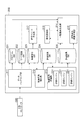
図1に示す生産システム1は、複数のローカル機器の協調動作によって、ワークの生産を行うシステムである。以下、ワークの生産過程において、各ローカル機器の作業対象となる物体の全てを「ワーク」という。例えば「ワーク」は、生産システム1における最終生産物、最終生産物の部品、及び複数の部品を組み合わせたユニット等を含む。
[Production system]
The production system 1 shown in FIG. 1 is a system that produces workpieces by cooperative operation of a plurality of local devices. Hereinafter, in the work production process, all the objects to be worked on by each local device are referred to as "work". For example, the "work" includes a final product in the production system 1, parts of the final product, a unit in which a plurality of parts are combined, and the like.

協調動作は、少なくとも一つの上記最終生産物を得るための複数の工程を分担するように複数のローカル機器が動作することを意味する。複数のローカル機器は、一つの最終生産物を得るための複数の工程を工程単位で分担するように動作してもよいし、複数の最終生産物を得るための複数の工程を最終生産物単位で分担するように動作してもよい。 Cooperative operation means that a plurality of local devices operate so as to share a plurality of steps for obtaining at least one final product. The plurality of local devices may operate so as to share a plurality of processes for obtaining one final product in a process unit, or a plurality of processes for obtaining a plurality of final products may be divided into a final product unit. It may operate so as to share with.

生産システム1は、複数のローカル機器2と、制御システム100とを含む。ローカル機器2は、ワーク9の生産現場においてワーク9に対し直接的に作業を実行する機器である。直接的な作業は、例えば、熱エネルギー、運動エネルギー、位置エネルギー等の何らかのエネルギーをワーク9に付与する作業である。複数のローカル機器2の少なくともいずれかは、少なくとも1つのサーボモータを含む。例えば複数のローカル機器2は、少なくともロボットを含む(少なくとも1つのローカル機器2はロボットである)。 The production system 1 includes a plurality of local devices 2 and a control system 100. The local device 2 is a device that directly executes work on the work 9 at the production site of the work 9. The direct work is, for example, the work of applying some energy such as thermal energy, kinetic energy, potential energy, etc. to the work 9. At least one of the plurality of local devices 2 includes at least one servomotor. For example, the plurality of local devices 2 include at least a robot (at least one local device 2 is a robot).

図1に示す複数のローカル機器2は、搬送装置2Aと、ロボット2B,2Cとを含んでいるが、これに限られない。少なくともいずれかのローカル機器2が少なくとも1つのサーボモータを含んでいる限り、ローカル機器2の数及び種類は適宜変更可能である。 The plurality of local devices 2 shown in FIG. 1 include, but are not limited to, the transfer device 2A and the robots 2B and 2C. As long as at least one of the local devices 2 includes at least one servomotor, the number and type of the local devices 2 can be changed as appropriate.

搬送装置2Aは、例えば電動式のサーボモータ等を動力源としてワーク9を搬送する。搬送装置2Aの具体例としては、ベルトコンベヤ、ローラコンベヤ等が挙げられる。ロボット2B,2Cは、搬送装置2Aが搬送するワーク9に対する作業を行う。ワーク9に対する作業の具体例としては、搬送装置2Aが搬送するワーク9(例えばベースパーツ)に対する他のワーク9(例えばサブパーツ)の組付け、搬送装置2Aが搬送するワーク9におけるパーツ同士の締結(例えばボルト締結)・接合(例えば溶接)等が挙げられる。 The transport device 2A transports the work 9 using, for example, an electric servomotor or the like as a power source. Specific examples of the transfer device 2A include a belt conveyor, a roller conveyor, and the like. The robots 2B and 2C perform work on the work 9 transported by the transport device 2A. Specific examples of the work on the work 9 include assembling another work 9 (for example, a sub-part) to the work 9 (for example, a base part) conveyed by the transfer device 2A, and fastening the parts in the work 9 conveyed by the transfer device 2A. (For example, bolt fastening), joining (for example, welding) and the like can be mentioned.

例えばロボット2B,2Cは、6軸の垂直多関節ロボットであり、図2に示すように、基部11と、旋回部12と、第1アーム13と、第2アーム14と、第3アーム17と、先端部18と、アクチュエータ41,42,43,44,45,46とを有する。基部11は、搬送装置2Aの周囲に設置されている。旋回部12は、鉛直な軸線21まわりに旋回するように基部11上に設けられている。第1アーム13は、軸線21に交差(例えば直交)する軸線22まわりに揺動するように旋回部12に接続されている。交差は、所謂立体交差のようにねじれの関係にある場合も含む。第2アーム14は、軸線22に実質的に平行な軸線23まわりに揺動するように第1アーム13の先端部に接続されている。第2アーム14は、アーム基部15とアーム端部16とを含む。アーム基部15は、第1アーム13の先端部に接続され、軸線23に交差(例えば直交)する軸線24に沿って延びている。アーム端部16は、軸線24まわりに旋回するようにアーム基部15の先端部に接続されている。第3アーム17は、軸線24に交差(例えば直交)する軸線25まわりに揺動するようにアーム端部16の先端部に接続されている。先端部18は、軸線25に交差(例えば直交)する軸線26まわりに旋回するように第3アーム17の先端部に接続されている。 For example, the robots 2B and 2C are 6-axis vertical articulated robots, and as shown in FIG. 2, the base portion 11, the swivel portion 12, the first arm 13, the second arm 14, and the third arm 17 , The tip portion 18, and the actuators 41, 42, 43, 44, 45, 46. The base 11 is installed around the transport device 2A. The swivel portion 12 is provided on the base portion 11 so as to swivel around the vertical axis 21. The first arm 13 is connected to the swivel portion 12 so as to swing around the axis 22 intersecting (for example, orthogonal to) the axis 21. The intersection also includes a case where there is a twisting relationship such as a so-called grade separation. The second arm 14 is connected to the tip of the first arm 13 so as to swing around an axis 23 substantially parallel to the axis 22. The second arm 14 includes an arm base 15 and an arm end 16. The arm base 15 is connected to the tip of the first arm 13 and extends along an axis 24 that intersects (for example, is orthogonal to) the axis 23. The arm end 16 is connected to the tip of the arm base 15 so as to swivel around the axis 24. The third arm 17 is connected to the tip end portion of the arm end portion 16 so as to swing around the axis line 25 intersecting (for example, orthogonal to) the axis line 24. The tip 18 is connected to the tip of the third arm 17 so as to swivel around an axis 26 that intersects (eg, is orthogonal) the axis 25.

このように、ロボット10は、基部11と旋回部12とを接続する関節31と、旋回部12と第1アーム13とを接続する関節32と、第1アーム13と第2アーム14とを接続する関節33と、第2アーム14においてアーム基部15とアーム端部16とを接続する関節34と、アーム端部16と第3アーム17とを接続する関節35と、第3アーム17と先端部18とを接続する関節36とを有する。 In this way, the robot 10 connects the joint 31 that connects the base 11 and the swivel portion 12, the joint 32 that connects the swivel portion 12 and the first arm 13, and the first arm 13 and the second arm 14. Joint 33, joint 34 connecting the arm base 15 and the arm end 16 in the second arm 14, joint 35 connecting the arm end 16 and the third arm 17, and the third arm 17 and the tip. It has a joint 36 that connects to 18.

アクチュエータ41,42,43,44,45,46は、例えば電動式のサーボモータ及び減速機を含み、関節31,32,33,34,35,36をそれぞれ駆動する。例えばアクチュエータ41は、軸線21まわりに旋回部12を旋回させ、軸線22まわりに第1アーム13を揺動させ、軸線23まわりに第2アーム14を揺動させ、軸線24まわりにアーム端部16を旋回させ、軸線25まわりに第3アーム17を揺動させ、軸線26まわりに先端部18を旋回させる。 Actuators 41, 42, 43, 44, 45, 46 include, for example, electric servomotors and reducers, and drive joints 31, 32, 33, 34, 35, 36, respectively. For example, the actuator 41 swings the swivel portion 12 around the axis 21, swings the first arm 13 around the axis 22, swings the second arm 14 around the axis 23, and swings the arm end 16 around the axis 24. Is swiveled, the third arm 17 is swung around the axis 25, and the tip 18 is swiveled around the axis 26.

なお、ロボット2B,2Cの具体的な構成は適宜変更可能である。例えばロボット2B,2Cは、上記6軸の垂直多関節ロボットに更に1軸の関節を追加した7軸の冗長型ロボットであってもよく、所謂スカラー型の多関節ロボットであってもよい。 The specific configurations of the robots 2B and 2C can be changed as appropriate. For example, the robots 2B and 2C may be a 7-axis redundant robot in which a 1-axis joint is added to the 6-axis vertical articulated robot, or may be a so-called scalar type articulated robot.

生産システム1は、検査装置5を更に備えてもよい。検査装置5は、ワーク9の品質を検査する。検査装置5の具体例としては、例えばワーク9の外観を検査するカメラが挙げられる。検査装置5は、レーザ光等により、ワーク9のサイズ等を検査するセンサであってもよい。生産システム1は、複数の検査装置5を備えてもよい。 The production system 1 may further include an inspection device 5. The inspection device 5 inspects the quality of the work 9. Specific examples of the inspection device 5 include a camera that inspects the appearance of the work 9. The inspection device 5 may be a sensor that inspects the size of the work 9 or the like with a laser beam or the like. The production system 1 may include a plurality of inspection devices 5.

〔制御システム〕
制御システム100は、上位コントローラ300と、複数のローカルコントローラ400と、情報収集装置200とを有する。複数のローカルコントローラ400は、複数のローカル機器2をそれぞれ制御する。例えばローカルコントローラ400は、制御対象のローカル機器2の動作指令を取得し、当該ローカル機器2の動作を動作指令に追従させる。
[Control system]
The control system 100 includes a host controller 300, a plurality of local controllers 400, and an information collecting device 200. The plurality of local controllers 400 control each of the plurality of local devices 2. For example, the local controller 400 acquires an operation command of the local device 2 to be controlled, and causes the operation of the local device 2 to follow the operation command.

例えばローカルコントローラ400は、動作指令に基づいて、ローカル機器2のモータに対するローカル指令信号を生成し、モータからフィードバック信号を取得し、ローカル指令信号とフィードバック信号とに基づいてモータを制御する。例えばローカルコントローラ400は、ローカル指令信号とフィードバック信号との偏差を縮小させるように駆動電力をモータに出力する。ローカルコントローラ400は、1つのモータに対して複数のローカル指令信号を生成し、1つのモータから複数のフィードバック信号を取得し、複数のローカル指令信号と複数のフィードバック信号とに基づいて1つのモータを制御してもよい。 For example, the local controller 400 generates a local command signal for the motor of the local device 2 based on the operation command, acquires a feedback signal from the motor, and controls the motor based on the local command signal and the feedback signal. For example, the local controller 400 outputs drive power to the motor so as to reduce the deviation between the local command signal and the feedback signal. The local controller 400 generates a plurality of local command signals for one motor, acquires a plurality of feedback signals from one motor, and makes one motor based on the plurality of local command signals and the plurality of feedback signals. You may control it.

ローカル指令信号の具体例としては、位置目標値(例えば回転角度目標値)を示す位置指令信号、速度目標値(例えば角速度目標値)を示す速度指令信号等が挙げられる。フィードバック信号の具体例としては、位置の検出値を示す位置信号、速度の検出値を示す速度信号、出力電流の指令値又は検出値を示す電流信号、出力電圧の指令値又は検出値を示す電圧信号等が挙げられる。 Specific examples of the local command signal include a position command signal indicating a position target value (for example, a rotation angle target value), a speed command signal indicating a speed target value (for example, an angular velocity target value), and the like. Specific examples of the feedback signal include a position signal indicating a position detection value, a speed signal indicating a speed detection value, an output current command value or a current signal indicating a detection value, and a voltage indicating an output voltage command value or a detection value. Signals and the like can be mentioned.

ローカル機器2が複数のモータを有する場合、ローカルコントローラ400は、モータごとに1つ又は複数のローカル指令信号を生成し、モータごとに1つ又は複数のフィードバック信号をそれぞれ取得し、複数のモータをそれぞれ制御する。 When the local device 2 has a plurality of motors, the local controller 400 generates one or a plurality of local command signals for each motor, acquires one or a plurality of feedback signals for each motor, and obtains a plurality of motors. Control each.

図1において、制御システム100は、3つのローカルコントローラ400A,400B,400Cを有する。ローカルコントローラ400Aは搬送装置2Aを制御し、ローカルコントローラ400Bはロボット2Bを制御し、ローカルコントローラ400Cはロボット2Cを制御する。ローカルコントローラ400の数及び各ローカルコントローラ400の構成は、ローカル機器2の数及び各ローカル機器2の種類に従って適宜変更可能である。 In FIG. 1, the control system 100 has three local controllers 400A, 400B, 400C. The local controller 400A controls the transfer device 2A, the local controller 400B controls the robot 2B, and the local controller 400C controls the robot 2C. The number of local controllers 400 and the configuration of each local controller 400 can be appropriately changed according to the number of local devices 2 and the type of each local device 2.

上位コントローラ300は、複数のローカルコントローラ400に対し動作指令を出力し、複数のローカルコントローラ400からステータス情報を取得する。ステータス情報は、1つ又は複数の上記ローカル指令信号及び1つ又は複数の上記フィードバック信号を含む。また、上位コントローラ300は、検査装置5からワーク9の検査結果を取得する。上位コントローラ300の具体例としては、ラダープログラムに従って動作するプログラマブルロジックコントローラが挙げられる。 The host controller 300 outputs an operation command to the plurality of local controllers 400, and acquires status information from the plurality of local controllers 400. The status information includes one or more of the local command signals and one or more of the feedback signals. Further, the host controller 300 acquires the inspection result of the work 9 from the inspection device 5. A specific example of the host controller 300 is a programmable logic controller that operates according to a ladder program.

情報収集装置200は、ローカル機器2の、複数の工程を含む動作時の内部情報である制御信号を、データベースに蓄積することと、データベースに蓄積された制御信号から複数の工程のいずれか1工程の実行中に蓄積された信号セットを抽出することと、抽出した信号セットを評価して、その評価結果を表す評価情報を生成することと、を実行するように構成されている。内部情報とは、ローカルコントローラ400と、制御対象のローカル機器2との間で閉じた制御ループ内で生成・取得される情報である。例えば制御信号は、上述した1つ又は複数のローカル指令信号と、1つ又は複数のフィードバック信号とを含む。 The information collecting device 200 stores the control signal, which is internal information of the local device 2 during operation including a plurality of steps, in the database, and one step of the plurality of steps from the control signal stored in the database. It is configured to extract the signal set accumulated during the execution of, and to evaluate the extracted signal set and generate evaluation information representing the evaluation result. The internal information is information generated / acquired in a closed control loop between the local controller 400 and the local device 2 to be controlled. For example, the control signal includes the one or more local command signals described above and one or more feedback signals.

情報収集装置200は、有線通信又は無線通信により複数のローカルコントローラ400から制御信号を取得する。一例として、情報収集装置200は、有線通信又は無線通信により上位コントローラ300と通信可能であり、上位コントローラ300を介して複数のローカルコントローラ400から制御信号を取得する。 The information collecting device 200 acquires control signals from a plurality of local controllers 400 by wired communication or wireless communication. As an example, the information collecting device 200 can communicate with the host controller 300 by wired communication or wireless communication, and acquires control signals from a plurality of local controllers 400 via the host controller 300.

図3に示すように、例えば情報収集装置200は、機能上の構成(以下、「機能ブロック」という。)として、データハンドリング部211と、制御信号抽出部212と、制御信号評価部213と、一覧画面生成部214とを有する。これらの機能ブロックは情報収集装置200の構成要素なので、各機能ブロックが実行する処理は、情報収集装置200が実行する処理である。 As shown in FIG. 3, for example, the information collecting device 200 has a data handling unit 211, a control signal extraction unit 212, and a control signal evaluation unit 213 as a functional configuration (hereinafter, referred to as “functional block”). It has a list screen generation unit 214. Since these functional blocks are components of the information collecting device 200, the processing executed by each functional block is the processing executed by the information collecting device 200.

データハンドリング部211は、ローカル機器2の制御信号を複数のローカルコントローラ400から取得し、データベースに蓄積する。データハンドリング部211は、ローカル機器2の動作時刻に関する時間情報を、データベースに更に蓄積してもよい。例えばデータハンドリング部211は、図4に例示するように、モータごとの位置指令信号、速度指令信号、位置信号、速度信号、電圧信号、電流信号等を、時刻に対応付けて制御信号データベース223に蓄積する。データハンドリング部211は、例えば情報収集装置200のタイマ(後述のシステムタイマ297)が測定した時刻に基づいて、時間情報を取得する。データハンドリング部211は、時間情報を上位コントローラ300又はローカルコントローラ400から取得してもよい。 The data handling unit 211 acquires the control signal of the local device 2 from the plurality of local controllers 400 and stores it in the database. The data handling unit 211 may further store time information regarding the operating time of the local device 2 in the database. For example, as illustrated in FIG. 4, the data handling unit 211 associates a position command signal, a speed command signal, a position signal, a speed signal, a voltage signal, a current signal, etc. for each motor with the time in the control signal database 223. accumulate. The data handling unit 211 acquires time information based on, for example, the time measured by the timer of the information collecting device 200 (system timer 297 described later). The data handling unit 211 may acquire the time information from the host controller 300 or the local controller 400.

データハンドリング部211は、ローカル機器2を動作させるプログラム(以下、「動作プログラム」という。)に関するプログラム情報を、データベースに更に蓄積してもよい。動作プログラムは、複数のジョブプログラムを含む。プログラム情報は、例えば制御対象のローカル機器2の識別情報と、各ジョブプログラムの識別情報とを含む。ジョブプログラムは、ローカル機器2の一まとまりの作業を表すプログラムである。一まとまりの作業の具体例としては、一連の経路に沿ったワーク9の搬送、一連の溶接ラインに沿ったワーク9の溶接、一連の塗装ラインに沿ったワーク9の塗装等が挙げられる。 The data handling unit 211 may further store program information regarding a program for operating the local device 2 (hereinafter, referred to as an “operation program”) in the database. The operation program includes a plurality of job programs. The program information includes, for example, identification information of the local device 2 to be controlled and identification information of each job program. The job program is a program that represents a set of work of the local device 2. Specific examples of the work as a group include transportation of the work 9 along a series of paths, welding of the work 9 along a series of welding lines, painting of the work 9 along a series of painting lines, and the like.

例えばデータハンドリング部211は、図5に例示するように、ジョブプログラムの識別情報(図中の「ジョブ」)と、開始時刻と、終了時刻とを対応付けてプログラムデータベース221に蓄積する。ジョブプログラムは、時系列の2以上の工程を含んでいてもよい。この場合、データハンドリング部211は、ジョブプログラムの識別情報に、工程の識別情報(図中の「ステップ」)を更に対応付け、各工程に開始時刻と終了時刻とを対応付けてプログラムデータベース221に蓄積する。 For example, as illustrated in FIG. 5, the data handling unit 211 stores the identification information of the job program (“job” in the figure), the start time, and the end time in association with each other in the program database 221. The job program may include two or more steps in a time series. In this case, the data handling unit 211 further associates the process identification information (“step” in the figure) with the job program identification information, and associates the start time and end time with each process in the program database 221. accumulate.

ジョブプログラムが2以上の工程を含む場合、複数の工程が、ジョブプログラムに関するジョブ情報(例えばジョブプログラムの識別情報)によって複数のグループにグルーピングされる。各グループは、同一ジョブプログラムに属する2以上の工程を含む。従って、ジョブプログラムの識別情報と、工程の識別情報とを対応付けてプログラムデータベース221に蓄積することは、ジョブ情報を含むグルーピング情報をデータベースに更に蓄積することの一例である。グルーピング情報は、複数の工程を、一まとまりの作業に属する2以上の工程ごとにグルーピングする情報である。 When the job program includes two or more processes, the plurality of processes are grouped into a plurality of groups by job information (for example, job program identification information) related to the job program. Each group includes two or more steps belonging to the same job program. Therefore, accumulating the identification information of the job program and the identification information of the process in the program database 221 in association with each other is an example of further accumulating the grouping information including the job information in the database. Grouping information is information for grouping a plurality of processes into two or more processes belonging to a group of operations.

データハンドリング部211は、ワーク9に関するワーク情報を、データベースに更に蓄積してもよい。例えば図5に例示するように、データハンドリング部211は、ジョブの識別情報と、工程の識別情報とに、ワーク9の種別(図中の「種別」)と、ワーク9の個体識別情報(図中の「シリアルNo.」)とを更に対応付けてプログラムデータベース221に蓄積する。 The data handling unit 211 may further accumulate work information regarding the work 9 in the database. For example, as illustrated in FIG. 5, the data handling unit 211 includes job identification information, process identification information, a work 9 type (“type” in the figure), and an individual identification information of the work 9 (FIG. 5). It is stored in the program database 221 in association with the "serial No.") in the program database 221.

ワーク9が、2以上の工程を含むローカル機器2の動作により生産される場合、当該ワーク9の個体識別情報が2以上の工程の識別情報に対応付けられることとなる。この場合、複数の工程が、ワーク情報によっても複数のグループにグルーピングされる。各グループは、同一ワークに対する2以上の工程を含む。従って、ワーク9の個体識別情報と、工程の識別情報とを対応付けてプログラムデータベース221に蓄積することは、ワーク情報を含むグルーピング情報をデータベースに更に蓄積することの一例である。 When the work 9 is produced by the operation of the local device 2 including the two or more steps, the individual identification information of the work 9 is associated with the identification information of the two or more steps. In this case, a plurality of processes are grouped into a plurality of groups according to the work information. Each group includes two or more steps for the same work. Therefore, accumulating the individual identification information of the work 9 and the identification information of the process in the program database 221 in association with each other is an example of further accumulating the grouping information including the work information in the database.

データハンドリング部211は、ワーク9の品質の検査結果を表す品質情報をデータベースに更に蓄積してもよい。例えば、図6に示すように、データハンドリング部211は、ワーク9の種別と、ワーク9の個体識別情報と、検査装置5による検査時刻と、検査装置5による検査結果とを対応付けてワーク品質データベース222に蓄積する。検査装置5による検査時刻は、検査装置5による検査結果をプログラムデータベース221が取得した時刻であってもよい。 The data handling unit 211 may further accumulate quality information representing the inspection result of the quality of the work 9 in the database. For example, as shown in FIG. 6, the data handling unit 211 associates the type of the work 9, the individual identification information of the work 9, the inspection time by the inspection device 5, and the inspection result by the inspection device 5 with the work quality. Accumulate in database 222. The inspection time by the inspection device 5 may be the time when the program database 221 acquires the inspection result by the inspection device 5.

図3に戻り、制御信号抽出部212は、制御信号データベース223に蓄積された制御信号から複数の工程のいずれか1工程の実行中に蓄積された信号セットを抽出する。制御信号抽出部212は、時間情報に基づいて信号セットを抽出してもよい。また、制御信号抽出部212は、プログラム情報に基づいて信号セットを抽出してもよい。例えば制御信号抽出部212は、上記1工程の開始時刻及び終了時刻をプログラムデータベース221から取得し、取得した開始時刻から終了時刻までの信号セットを制御信号データベース223から抽出する。 Returning to FIG. 3, the control signal extraction unit 212 extracts the signal set accumulated during the execution of any one of the plurality of steps from the control signals stored in the control signal database 223. The control signal extraction unit 212 may extract a signal set based on the time information. Further, the control signal extraction unit 212 may extract a signal set based on the program information. For example, the control signal extraction unit 212 acquires the start time and end time of the above one process from the program database 221 and extracts the signal set from the acquired start time to the end time from the control signal database 223.

なお、時間情報を媒介変数として制御信号を抽出することは必須ではない。例えば、プログラムデータベース221と制御信号データベース223とが一つのデータベースにまとめられている場合、制御信号抽出部212は、上記1工程の識別情報に基づいて、当該1工程の信号セットを抽出し得る。 It is not essential to extract the control signal using the time information as a parameter. For example, when the program database 221 and the control signal database 223 are combined into one database, the control signal extraction unit 212 can extract the signal set of the one step based on the identification information of the one step.

制御信号抽出部212は、ワーク情報に基づいて信号セットを抽出してもよい。例えば、制御信号抽出部212は、ワーク9の個体識別情報に対応付けられた工程の開始時刻及び終了時刻をプログラムデータベース221から取得し、取得した開始時刻から終了時刻までの信号セットを制御信号データベース223から抽出する。 The control signal extraction unit 212 may extract a signal set based on the work information. For example, the control signal extraction unit 212 acquires the start time and end time of the process associated with the individual identification information of the work 9 from the program database 221 and obtains the signal set from the acquired start time to the end time in the control signal database. Extract from 223.

なお、この場合も、時間情報を媒介変数として制御信号を抽出することは必須ではない。例えば、プログラムデータベース221と制御信号データベース223とが一つのデータベースにまとめられている場合、制御信号抽出部212は、上記ワーク9の個体識別情報に基づいて、当該ワーク9に対応する工程の信号セットを抽出し得る。 Also in this case, it is not essential to extract the control signal using the time information as a parameter. For example, when the program database 221 and the control signal database 223 are combined into one database, the control signal extraction unit 212 sets a signal for the process corresponding to the work 9 based on the individual identification information of the work 9. Can be extracted.

制御信号抽出部212は、ワーク品質データベース222におけるワーク9の検査時刻から、当該ワーク9に対する工程の開始時刻及び終了時刻を逆算し、逆算した開始時刻から終了時刻までの信号セットを制御信号データベース223から抽出してもよい。制御信号抽出部212は、抽出した信号セットを評価対象データベース224に格納する。 The control signal extraction unit 212 back-calculates the start time and end time of the process for the work 9 from the inspection time of the work 9 in the work quality database 222, and calculates the back-calculated signal set from the start time to the end time in the control signal database 223. It may be extracted from. The control signal extraction unit 212 stores the extracted signal set in the evaluation target database 224.

制御信号抽出部212は、同一の工程を指定する抽出条件に基づいて信号セットを繰り返し抽出し、評価対象データベース224に蓄積してもよい。例えば制御信号抽出部212は、工程の識別情報を指定する工程条件に基づいて、工程の識別情報が工程条件を満たす工程の信号セットを繰り返し抽出してもよい。また、制御信号抽出部212は、ワーク9の種別を指定するワーク条件に基づいて、ワーク9の種別がワーク条件を満たす工程の信号セットを繰り返し抽出してもよい。 The control signal extraction unit 212 may repeatedly extract the signal set based on the extraction conditions that specify the same process and store it in the evaluation target database 224. For example, the control signal extraction unit 212 may repeatedly extract a signal set of a process in which the process identification information satisfies the process condition, based on the process condition for designating the process identification information. Further, the control signal extraction unit 212 may repeatedly extract a signal set of a process in which the type of the work 9 satisfies the work condition based on the work condition for specifying the type of the work 9.

制御信号抽出部212は、同一の工程であって、且つ同一の時間帯に実行された工程を指定する抽出条件に基づいて信号セットを繰り返し抽出してもよい。例えば制御信号抽出部212は、工程の識別情報を指定する工程条件と、時間帯を指定する時間条件に基づいて、工程の識別情報が工程条件を満たし、開始時刻及び終了時刻が時間条件を満たす工程の信号セットを繰り返し抽出してもよい。また、制御信号抽出部212は、ワーク9の種別を指定するワーク条件と、時間帯を指定する時間条件に基づいて、ワーク9の種別がワーク条件を満たし、開始時刻及び終了時刻が時間条件を満たす工程の信号セットを繰り返し抽出してもよい。 The control signal extraction unit 212 may repeatedly extract the signal set based on the extraction conditions that specify the processes that are the same process and that are executed in the same time zone. For example, in the control signal extraction unit 212, the process identification information satisfies the process conditions, and the start time and the end time satisfy the time conditions based on the process conditions for designating the process identification information and the time conditions for specifying the time zone. The signal set of the process may be extracted repeatedly. Further, in the control signal extraction unit 212, the type of the work 9 satisfies the work condition, and the start time and the end time set the time condition based on the work condition for specifying the type of the work 9 and the time condition for specifying the time zone. The signal set of the satisfying step may be repeatedly extracted.

例えば制御信号抽出部212は、工程の識別情報を指定する工程条件と、時間帯を指定する時間条件に基づいて、工程の識別情報が工程条件を満たし、開始時刻、及び終了時刻が時間条件を満たす工程の信号セットを繰り返し抽出してもよい。制御信号抽出部212は、同一の工程であって、且つ同一の時間帯に実行された工程を指定する抽出条件に基づいて信号セットを繰り返し抽出してもよい。 For example, in the control signal extraction unit 212, the process identification information satisfies the process conditions, and the start time and the end time set the time conditions based on the process conditions for designating the process identification information and the time conditions for specifying the time zone. The signal set of the process to be satisfied may be repeatedly extracted. The control signal extraction unit 212 may repeatedly extract the signal set based on the extraction conditions that specify the processes that are the same process and that are executed in the same time zone.

制御信号抽出部212は、上記グルーピング情報に基づいて、同一グループに属する2以上の工程にそれぞれ対応する2以上の信号セットを同一グループの信号セットとして抽出し、評価対象データベース224に格納してもよい。例えば制御信号抽出部212は、少なくとも上記ワーク情報に基づいて、同一ワークに対する2以上の工程にそれぞれ対応する2以上の信号セットを、同一グループの信号セットとして抽出してもよい。また、制御信号抽出部212は、少なくとも上記ジョブ情報に基づいて、同一ジョブに属する2以上の工程にそれぞれ対応する2以上の信号セットを、同一グループの信号セットとして抽出してもよい。 Based on the grouping information, the control signal extraction unit 212 may extract two or more signal sets corresponding to two or more processes belonging to the same group as signal sets of the same group and store them in the evaluation target database 224. good. For example, the control signal extraction unit 212 may extract two or more signal sets corresponding to two or more steps for the same work as a signal set of the same group, based on at least the work information. Further, the control signal extraction unit 212 may extract two or more signal sets corresponding to two or more processes belonging to the same job as a signal set of the same group, based on at least the job information.

制御信号評価部213は、制御信号抽出部212が抽出した信号セットを評価して、その評価結果を表す評価情報を生成する。信号セットの評価の具体例としては、信号セットの大きさ(以下、「信号レベル」という。)と、所定の基準レベルとの比較評価が挙げられる。この場合、評価情報は、信号レベルが基準レベルを超えているか否かを示す情報であってもよく、信号レベルが基準レベルを下回っているか否かを示す情報であってもよい。評価情報は、信号レベルと基準レベルとの差分を示す情報であってもよい。 The control signal evaluation unit 213 evaluates the signal set extracted by the control signal extraction unit 212, and generates evaluation information representing the evaluation result. Specific examples of the evaluation of the signal set include a comparative evaluation between the size of the signal set (hereinafter referred to as “signal level”) and a predetermined reference level. In this case, the evaluation information may be information indicating whether or not the signal level exceeds the reference level, or may be information indicating whether or not the signal level is below the reference level. The evaluation information may be information indicating the difference between the signal level and the reference level.

制御信号評価部213は、制御信号抽出部212により抽出された評価対象の信号セットと、過去に制御信号抽出部212により抽出された少なくとも一つの比較対象の信号セットとに基づいて評価対象の信号セットの評価情報を生成してもよい。この場合、評価情報は、評価対象の信号セットの信号レベルと、比較対象の信号セットの信号レベルとの差分を示す情報(以下、「異常度」という。)であってもよく、異常度が所定の基準乖離レベルを超えているか否かを示す情報であってもよく、異常度が当該基準乖離レベルを下回っているか否かを示す情報であってもよい。 The control signal evaluation unit 213 evaluates the signal to be evaluated based on the signal set to be evaluated extracted by the control signal extraction unit 212 and at least one comparison target signal set extracted by the control signal extraction unit 212 in the past. The evaluation information of the set may be generated. In this case, the evaluation information may be information indicating the difference between the signal level of the signal set to be evaluated and the signal level of the signal set to be compared (hereinafter, referred to as “abnormality”), and the degree of abnormality may be. It may be information indicating whether or not the predetermined reference deviation level is exceeded, or may be information indicating whether or not the degree of abnormality is below the reference reference deviation level.

制御信号評価部213は、信号セットが入力されると評価情報を出力する複数種類の評価エンジン231のいずれか1つを、信号セットの抽出条件に基づいて選択し、信号セットと、選択した評価エンジンとに基づいて評価情報を生成してもよい。図中には、3つの評価エンジン231を示しているが、評価エンジンの数はこれに限られない。 The control signal evaluation unit 213 selects one of a plurality of types of evaluation engines 231 that output evaluation information when a signal set is input based on the extraction conditions of the signal set, and sets the signal and the selected evaluation. Evaluation information may be generated based on the engine. Although three evaluation engines 231 are shown in the figure, the number of evaluation engines is not limited to this.

複数種類の評価エンジン231の具体例としては、上記基準レベルが互いに異なる複数の評価エンジン231、上記基準乖離レベルが互いに異なる複数の評価エンジン231が挙げられる。いずれかの評価エンジン231が、上記信号セットの信号レベルと上記基準レベルとを比較するエンジンであり、他の評価エンジン231が、上記評価対象の信号セットの信号レベルと上記比較対象の信号セットの信号レベルとを比較するエンジンであってもよい。 Specific examples of the plurality of types of evaluation engines 231 include a plurality of evaluation engines 231 having different reference levels, and a plurality of evaluation engines 231 having different reference deviation levels. One of the evaluation engines 231 is an engine that compares the signal level of the signal set with the reference level, and the other evaluation engine 231 compares the signal level of the signal set of the evaluation target with the signal level of the comparison target. It may be an engine that compares with the signal level.

制御信号評価部213は、生成した評価情報を、ジョブプログラムの識別情報、工程の識別情報、ワーク9の種別、ワーク9の個体識別情報等と対応付けて評価結果データベース225に格納する。上述したように、制御信号抽出部212が上記抽出条件に基づいて信号セットを繰り返し抽出する場合、制御信号評価部213は、制御信号抽出部212が繰り返し抽出した複数の信号セットを評価し、その評価結果をそれぞれ表す複数の評価情報(以下、「追跡対象の評価情報」という。)を生成して評価結果データベース225に蓄積してもよい。 The control signal evaluation unit 213 stores the generated evaluation information in the evaluation result database 225 in association with the job program identification information, the process identification information, the work 9 type, the work 9 individual identification information, and the like. As described above, when the control signal extraction unit 212 repeatedly extracts the signal set based on the above extraction conditions, the control signal evaluation unit 213 evaluates a plurality of signal sets repeatedly extracted by the control signal extraction unit 212, and evaluates the plurality of signal sets. A plurality of evaluation information representing each evaluation result (hereinafter, referred to as “tracking target evaluation information”) may be generated and stored in the evaluation result database 225.

制御信号評価部213は、制御信号抽出部212が抽出した上記同一グループの信号セットのそれぞれを評価し、その評価結果をそれぞれ表す複数の評価情報(以下、「同一グループの評価情報」という。)を生成して評価結果データベース225に蓄積してもよい。 The control signal evaluation unit 213 evaluates each of the signal sets of the same group extracted by the control signal extraction unit 212, and a plurality of evaluation information representing the evaluation results (hereinafter, referred to as "evaluation information of the same group"). May be generated and stored in the evaluation result database 225.

一覧画面生成部214は、評価結果データベース225に蓄積された同一グループの評価情報をグループごとに表示する一覧画面を生成し、表示デバイス等に表示させる。一覧画面生成部214は、ワーク品質データベース222に蓄積された品質情報をワーク9ごとに表示する品質一覧画面を更に生成し、表示デバイス等に表示させてもよい。 The list screen generation unit 214 generates a list screen that displays the evaluation information of the same group accumulated in the evaluation result database 225 for each group, and displays it on a display device or the like. The list screen generation unit 214 may further generate a quality list screen that displays the quality information accumulated in the work quality database 222 for each work 9, and display it on a display device or the like.

一覧画面生成部214は、図7、図8及び図9に例示するように、一覧画面と品質一覧画面とを一画面で表示するように生成してもよい。図7の画面においては、各行において、ワーク9の検査時刻と、ワーク9の種別と、ワーク9の個体識別情報と、同一グループ(ワーク9に対応するグループ)の評価情報(図中の「ステップ1評価」、「・・・」、「ステップN評価」)と、検査結果とが対応付けられている。 The list screen generation unit 214 may generate the list screen and the quality list screen on one screen, as illustrated in FIGS. 7, 8 and 9. On the screen of FIG. 7, in each line, the inspection time of the work 9, the type of the work 9, the individual identification information of the work 9, and the evaluation information of the same group (the group corresponding to the work 9) (“step” in the figure). 1 evaluation ”,“ ... ”,“ Step N evaluation ”) and the inspection result are associated with each other.

図8の画面においては、各行において、評価情報の生成時刻(図中の「解析時刻」)と、ジョブプログラムの実行開始時刻(図中の「開始時刻」)と、ジョブプログラムの実行終了時刻(図中の「終了時刻」)と、ジョブプログラムの識別情報(図中の「ジョブ」)と、同一グループ(ジョブプログラムに対応するグループ)の評価情報(図中の「ステップ1評価」、「・・・」、「ステップN評価」)とが対応付けられている。 In the screen of FIG. 8, in each line, the evaluation information generation time (“analysis time” in the figure), the job program execution start time (“start time” in the figure), and the job program execution end time (“start time” in the figure) ( "End time" in the figure), job program identification information ("job" in the figure), and evaluation information of the same group (group corresponding to the job program) ("step 1 evaluation", "・・ ・ ”,“ Step N evaluation ”) are associated with each other.

図9の画面においては、各行において、ワーク9の検査時刻と、ワーク9の種別と、ワーク9の個体識別情報と、ジョブプログラムの識別情報と、同一グループ(ジョブプログラムに対応するグループ)の評価情報とが対応付けられている。 On the screen of FIG. 9, in each line, the inspection time of the work 9, the type of the work 9, the individual identification information of the work 9, the identification information of the job program, and the evaluation of the same group (group corresponding to the job program). Information is associated with it.

上述のように、制御信号評価部213が追跡対象の評価情報を評価結果データベース225に蓄積する場合、一覧画面生成部214は、一覧画面において、いずれのワーク又はジョブプログラムが追跡対象の評価情報であるかを視認させる強調表示を行ってもよい。 As described above, when the control signal evaluation unit 213 stores the evaluation information of the tracking target in the evaluation result database 225, the list screen generation unit 214 uses the evaluation information of the tracking target for any work or job program on the list screen. You may make a highlighting to visually recognize the existence.

図2に戻り、情報収集装置200は、動作評価部215を更に有してもよい。動作評価部215は、評価結果データベース225に蓄積された、同一グループの信号セットの評価情報に基づいて、当該グループに対応するローカル機器2の動作の評価結果を表す動作評価情報を生成する。例えば評価結果データベース225は、同一グループの信号セットの評価情報に統計処理を施して動作評価情報を生成する。例えば評価結果データベース225は、同一グループの信号セットの評価情報の平均値、最大値、最小値等を動作評価情報として生成する。 Returning to FIG. 2, the information collecting device 200 may further have an operation evaluation unit 215. The operation evaluation unit 215 generates operation evaluation information representing the operation evaluation result of the local device 2 corresponding to the group based on the evaluation information of the signal set of the same group accumulated in the evaluation result database 225. For example, the evaluation result database 225 performs statistical processing on the evaluation information of the signal set of the same group to generate the operation evaluation information. For example, the evaluation result database 225 generates the average value, the maximum value, the minimum value, and the like of the evaluation information of the signal set of the same group as the operation evaluation information.

情報収集装置200が動作評価部215を有する場合、一覧画面生成部214は、動作評価情報をグループごとに表示する一覧画面を生成してもよい(図7、図8及び図9参照)。 When the information collecting device 200 has the operation evaluation unit 215, the list screen generation unit 214 may generate a list screen for displaying the operation evaluation information for each group (see FIGS. 7, 8 and 9).

一覧画面生成部214は、図10の(a)に示すように、同一グループの評価情報は表示せずに、動作評価情報をグループごとに表示する一覧画面を生成してもよい。この場合、一覧画面生成部214は、図10の(a)の画面において、いずれかのグループが選択されるのに応じて、同一グループの評価情報を表示する一覧画面(図10の(b)参照)を生成してもよい。 As shown in FIG. 10A, the list screen generation unit 214 may generate a list screen that displays the operation evaluation information for each group without displaying the evaluation information of the same group. In this case, the list screen generation unit 214 displays the evaluation information of the same group in response to the selection of any group on the screen of FIG. 10 (a) ((b) of FIG. 10). See) may be generated.

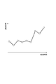
制御信号評価部213が上記追跡対象の評価情報を生成して評価結果データベース225に蓄積する場合、情報収集装置200は、経時変化画面生成部216を更に有してもよい。経時変化画面生成部216は、追跡対象の評価情報に基づいて、評価情報の経時変化を表す経時変化画面を生成し、表示デバイス等に表示する。経時変化画面の生成及び表示は、例えば図7〜10のいずれかの画面における所定の部分に対して操作(例えばマウスのクリック操作)が行われるのに応じて実行される。図11は、経時変化画面を例示するグラフである。グラフの横軸は経過時間を表し、グラフの縦軸は評価情報の大きさを表している。 When the control signal evaluation unit 213 generates the evaluation information of the tracking target and stores it in the evaluation result database 225, the information collecting device 200 may further include a time-dependent screen generation unit 216. The time-dependent change screen generation unit 216 generates a time-dependent change screen showing the time-dependent change of the evaluation information based on the evaluation information of the tracking target, and displays it on a display device or the like. The generation and display of the time-dependent screen is executed, for example, in response to an operation (for example, a mouse click operation) performed on a predetermined portion of the screen shown in FIGS. 7 to 10. FIG. 11 is a graph illustrating a time-dependent change screen. The horizontal axis of the graph represents the elapsed time, and the vertical axis of the graph represents the size of the evaluation information.

情報収集装置200は、信号チャート生成部217を更に有してもよい。信号チャート生成部217は、ユーザにより指定された期間における制御信号の経時変化を表す信号チャート画面を生成し、表示デバイス等に表示する。例えば、信号チャート生成部217は、図7においていずれかの検査時刻が選択された場合に、当該検査時刻よりも所定期間前から当該検査時刻までの期間の信号チャート画面を生成する。また、信号チャート生成部217は、図8においていずれかのジョブプログラムの識別情報が選択された場合に、当該ジョブプログラムの開始時刻から終了時刻までの期間の信号チャート画面を生成する。信号チャート画面の生成及び表示は、例えば図7〜10のいずれかの画面における所定の部分に対して操作(例えばマウスのクリック操作)が行われるのに応じて実行される。図12は、信号チャート画面を例示するグラフである。グラフの横軸は経過時間を表し、グラフの縦軸は制御信号の大きさを表している。 The information collecting device 200 may further include a signal chart generation unit 217. The signal chart generation unit 217 generates a signal chart screen showing a change over time of the control signal in a period designated by the user, and displays it on a display device or the like. For example, when any inspection time is selected in FIG. 7, the signal chart generation unit 217 generates a signal chart screen for a period from a predetermined period before the inspection time to the inspection time. Further, the signal chart generation unit 217 generates a signal chart screen for a period from the start time to the end time of the job program when the identification information of any of the job programs is selected in FIG. The generation and display of the signal chart screen is executed, for example, in response to an operation (for example, a mouse click operation) performed on a predetermined portion of the screen of any one of FIGS. 7 to 10. FIG. 12 is a graph illustrating a signal chart screen. The horizontal axis of the graph represents the elapsed time, and the vertical axis of the graph represents the magnitude of the control signal.

以上に示した情報収集装置200の構成はあくまで一例であり、適宜変更可能である。例えば情報収集装置200は、評価情報の生成と蓄積を定期的に実行するように構成されていてもよいし、一覧画面を表示する度に評価情報を生成するように構成されていてもよい。また、情報収集装置200は、評価結果データベース225に蓄積された評価情報に基づいて、ISO9001等に準拠した評価レポートを自動生成するように構成されていてもよい。 The configuration of the information collecting device 200 shown above is merely an example, and can be changed as appropriate. For example, the information collecting device 200 may be configured to periodically generate and store evaluation information, or may be configured to generate evaluation information each time a list screen is displayed. Further, the information collecting device 200 may be configured to automatically generate an evaluation report conforming to ISO9001 or the like based on the evaluation information accumulated in the evaluation result database 225.

図13は、情報収集装置200のハードウェア構成を例示するブロック図である。図13に示すように、情報収集装置200は、少なくとも一つのプロセッサ291と、メモリ292と、ストレージ293と、通信ポート294と、表示デバイス295と、入力デバイス296と、システムタイマ297とを有する。ストレージ293は、例えばハードディスク等、コンピュータによって読み取り可能な記憶媒体を有する。記憶媒体は、不揮発性の半導体メモリ、磁気ディスク及び光ディスク等の取り出し可能な媒体であってもよい。ストレージ293は、サーボモータを含むローカル機器の、複数の工程を含む動作時の内部情報である制御信号を、データベースに蓄積することと、データベースに蓄積された制御信号から複数の工程のいずれか1工程の実行中に蓄積された信号セットを抽出することと、制御信号抽出部212が抽出した信号セットを評価して、その評価結果を表す評価情報を生成することと、を装置に実行させるプログラムを記憶している。例えばストレージ293は、上述した情報収集装置200の各機能ブロックを構成するためのプログラムを記憶している。 FIG. 13 is a block diagram illustrating a hardware configuration of the information collecting device 200. As shown in FIG. 13, the information collecting device 200 includes at least one processor 291, a memory 292, a storage 293, a communication port 294, a display device 295, an input device 296, and a system timer 297. The storage 293 has a computer-readable storage medium, such as a hard disk. The storage medium may be a removable medium such as a non-volatile semiconductor memory, a magnetic disk, or an optical disk. The storage 293 stores the control signal, which is internal information of the local device including the servomotor during operation including a plurality of steps, in the database, and any one of the plurality of steps from the control signal stored in the database. A program that causes the device to execute the extraction of the signal set accumulated during the execution of the process, the evaluation of the signal set extracted by the control signal extraction unit 212, and the generation of evaluation information representing the evaluation result. I remember. For example, the storage 293 stores a program for configuring each functional block of the information collecting device 200 described above.

メモリ292は、ストレージ293からロードしたプログラム及びプロセッサ291による演算結果を一時的に記憶する。プロセッサ291は、メモリ292と協働して上記プログラムを実行することで、上述した各機能ブロックを構成する。通信ポート294は、プロセッサ291からの指令に従って、ネットワーク回線NW1を介して、上位コントローラ300との間で通信を行う。 The memory 292 temporarily stores the program loaded from the storage 293 and the calculation result by the processor 291. The processor 291 constitutes each of the above-mentioned functional blocks by executing the above program in cooperation with the memory 292. The communication port 294 communicates with the host controller 300 via the network line NW1 in accordance with a command from the processor 291.

表示デバイス295及び入力デバイス296は、情報収集装置200のユーザインタフェースとして機能する。表示デバイス295は、例えば液晶モニタ等を含み、ユーザに対する情報表示に用いられる。入力デバイス296は、例えばキーパッド等であり、ユーザによる入力情報を取得する。表示デバイス295及び入力デバイス296は、所謂タッチパネルのように一体化されていてもよい。表示デバイス295及び入力デバイス296は、情報収集装置200に組み込まれていてもよいし、情報収集装置200に接続される外部機器に設けられていてもよい。システムタイマ297は、例えば一定周期の基準クロックパルスをカウントすることにより、経過時間を計測する。 The display device 295 and the input device 296 function as a user interface of the information collecting device 200. The display device 295 includes, for example, a liquid crystal monitor and is used for displaying information to the user. The input device 296 is, for example, a keypad or the like, and acquires input information by the user. The display device 295 and the input device 296 may be integrated like a so-called touch panel. The display device 295 and the input device 296 may be incorporated in the information collecting device 200, or may be provided in an external device connected to the information collecting device 200. The system timer 297 measures the elapsed time, for example, by counting a reference clock pulse having a fixed cycle.

〔情報収集手順〕
続いて、情報収集方法の一例として、情報収集装置200が実行する情報収集手順を例示する。この手順は、サーボモータを含むローカル機器の、複数の工程を含む動作時の内部情報である制御信号を、データベースに蓄積することと、データベースに蓄積された制御信号から複数の工程のいずれか1工程の実行中に蓄積された信号セットを抽出することと、制御信号抽出部が抽出した信号セットを評価して、その評価結果を表す評価情報を生成することと、を含む。以下、情報収集手順を、「信号蓄積手順」、「信号評価手順」、「一覧画面の生成手順」、「経時変化画面の生成手順」、及び「信号チャート画面の生成手順」に分けて詳細に例示する。
[Information collection procedure]
Subsequently, as an example of the information collection method, an information collection procedure executed by the information collection device 200 will be illustrated. In this procedure, the control signal, which is internal information of the local device including the servomotor during operation including a plurality of steps, is stored in the database, and the control signal stored in the database is used as one of the plurality of steps. This includes extracting the signal set accumulated during the execution of the process, evaluating the signal set extracted by the control signal extraction unit, and generating evaluation information representing the evaluation result. Below, the information collection procedure is divided into "signal storage procedure", "signal evaluation procedure", "list screen generation procedure", "time-varying screen generation procedure", and "signal chart screen generation procedure" in detail. Illustrate.

(信号蓄積手順)
信号蓄積手順は、制御信号と、ワーク9の品質情報とを蓄積する手順である。図14に示すように、情報収集装置200は、まずステップS01,S02を実行する。ステップS01では、データハンドリング部211が、ローカル機器2の制御信号を複数のローカルコントローラ400から取得し、制御信号データベース223に蓄積する。ステップS02では、動作プログラムの1工程が完了したか否かをデータハンドリング部211が完了する。
(Signal storage procedure)
The signal storage procedure is a procedure for storing the control signal and the quality information of the work 9. As shown in FIG. 14, the information collecting device 200 first executes steps S01 and S02. In step S01, the data handling unit 211 acquires the control signal of the local device 2 from the plurality of local controllers 400 and stores it in the control signal database 223. In step S02, the data handling unit 211 completes whether or not one step of the operation program is completed.

ステップS02において動作プログラムの1工程が完了したと判定した場合、情報収集装置200はステップS03を実行する。ステップS03では、データハンドリング部211が、完了した工程のプログラム情報をプログラムデータベース221に蓄積する。 When it is determined in step S02 that one step of the operation program is completed, the information collecting device 200 executes step S03. In step S03, the data handling unit 211 stores the program information of the completed process in the program database 221.

次に、情報収集装置200は、ステップS04を実行する。ステップS02において動作プログラムの1工程が完了していないと判定した場合、情報収集装置200は、ステップS03を実行することなくステップS04を実行する。ステップS04では、検査装置5による検査が完了したか否かをデータハンドリング部211が確認する。 Next, the information collecting device 200 executes step S04. If it is determined in step S02 that one step of the operation program has not been completed, the information collecting device 200 executes step S04 without executing step S03. In step S04, the data handling unit 211 confirms whether or not the inspection by the inspection device 5 is completed.

ステップS04において検査が完了したと判定した場合、情報収集装置200はステップS05を実行する。ステップS05では、データハンドリング部211が、上位コントローラ300等からワーク9の品質の検査結果を取得してワーク品質データベース222に蓄積する。その後、情報収集装置200は処理をステップS01に戻す。ステップS04において検査が完了していないと判定した場合、情報収集装置200はステップS05を実行することなく処理をステップS01に戻す。情報収集装置200は以上の処理を繰り返す。これにより、制御信号データベース223に制御信号が蓄積され、ワーク品質データベース222にワーク9の品質の検査結果が蓄積される。 If it is determined in step S04 that the inspection is completed, the information collecting device 200 executes step S05. In step S05, the data handling unit 211 acquires the quality inspection result of the work 9 from the host controller 300 or the like and stores it in the work quality database 222. After that, the information collecting device 200 returns the process to step S01. If it is determined in step S04 that the inspection has not been completed, the information collecting device 200 returns the process to step S01 without executing step S05. The information collecting device 200 repeats the above processing. As a result, the control signal is accumulated in the control signal database 223, and the inspection result of the quality of the work 9 is accumulated in the work quality database 222.

(信号評価手順)
信号評価手順は、制御信号データベース223に蓄積された制御信号を工程ごとに評価する手順である。図15に示すように、情報収集装置200は、まずステップS11,S12,S13,S14,S15を実行する。ステップS11では、制御信号抽出部212が制御信号の抽出対象の時刻を設定する。例えば制御信号抽出部212は、抽出条件を満たす工程の開始時刻及び終了時刻をプログラムデータベース221から取得する。ステップS12では、制御信号抽出部212が、取得した開始時刻から終了時刻までの信号セットを制御信号データベース223から抽出する。ステップS13では、制御信号抽出部212が、抽出した信号セットを評価対象データベース224に格納する。
(Signal evaluation procedure)
The signal evaluation procedure is a procedure for evaluating the control signal stored in the control signal database 223 for each process. As shown in FIG. 15, the information collecting device 200 first executes steps S11, S12, S13, S14, and S15. In step S11, the control signal extraction unit 212 sets the time of the control signal extraction target. For example, the control signal extraction unit 212 acquires the start time and end time of the process satisfying the extraction condition from the program database 221. In step S12, the control signal extraction unit 212 extracts the acquired signal set from the start time to the end time from the control signal database 223. In step S13, the control signal extraction unit 212 stores the extracted signal set in the evaluation target database 224.

ステップS14では、制御信号評価部213が、制御信号抽出部212による信号セットの抽出条件に基づいて、複数種類の評価エンジン231のいずれかを選択する。ステップS15では、制御信号抽出部212が抽出した信号セットと、選択した評価エンジン231とに基づいて、制御信号評価部213が評価情報を生成する。 In step S14, the control signal evaluation unit 213 selects one of a plurality of types of evaluation engines 231 based on the signal set extraction conditions by the control signal extraction unit 212. In step S15, the control signal evaluation unit 213 generates evaluation information based on the signal set extracted by the control signal extraction unit 212 and the selected evaluation engine 231.

選択した評価エンジン231が、上記評価対象の信号セットの信号レベルと上記比較対象の信号セットの信号レベルとを比較するエンジンである場合、制御信号評価部213は、例えば図16のステップS21を実行する。ステップS21では、制御信号評価部213が、評価対象データベース224に所定数の比較対象の信号セットが蓄積されているか否かを確認する。 When the selected evaluation engine 231 is an engine that compares the signal level of the signal set to be evaluated with the signal level of the signal set to be compared, the control signal evaluation unit 213 executes, for example, step S21 of FIG. do. In step S21, the control signal evaluation unit 213 confirms whether or not a predetermined number of signal sets to be compared are accumulated in the evaluation target database 224.

ステップS21において所定数の比較対象の信号セットが蓄積されていると判定した場合、情報収集装置200は、ステップS22を実行する。ステップS22では、制御信号評価部213は、評価対象の信号セットの信号レベルと比較対象の信号セットの信号レベルとの差を上記異常度として算出する。ステップS21において所定数の比較対象の信号セットが蓄積されていないと判定した場合、情報収集装置200は、ステップS22を実行せずに信号セットの評価を完了する。 When it is determined in step S21 that a predetermined number of signal sets to be compared are accumulated, the information collecting device 200 executes step S22. In step S22, the control signal evaluation unit 213 calculates the difference between the signal level of the signal set to be evaluated and the signal level of the signal set to be compared as the abnormality degree. When it is determined in step S21 that a predetermined number of signal sets to be compared are not accumulated, the information collecting device 200 completes the evaluation of the signal sets without executing step S22.

図15に戻り、情報収集装置200は、次にステップS16,S17を実行する。ステップS16では、制御信号評価部213が、評価情報を評価結果データベース225に蓄積する。ステップS17では、制御信号抽出部212が、抽出条件を満たす全ての工程の評価が完了したかを確認する。 Returning to FIG. 15, the information collecting device 200 then executes steps S16 and S17. In step S16, the control signal evaluation unit 213 stores the evaluation information in the evaluation result database 225. In step S17, the control signal extraction unit 212 confirms whether the evaluation of all the steps satisfying the extraction conditions has been completed.

ステップS17において評価が完了していない工程が残っていると判定した場合、情報収集装置200は処理をステップS11に戻す。以後、抽出条件を満たす全ての工程の評価が完了するまで、信号セットの抽出と評価とが繰り返される。 If it is determined in step S17 that there are still steps for which evaluation has not been completed, the information collecting device 200 returns the process to step S11. After that, the extraction and evaluation of the signal set are repeated until the evaluation of all the steps satisfying the extraction conditions is completed.

ステップS17において全ての工程の評価が完了したと判定した場合、情報収集装置200は信号評価手順を完了する。情報収集装置200は、以上の信号評価手順を定期的に繰り返す。 When it is determined in step S17 that the evaluation of all the steps is completed, the information collecting device 200 completes the signal evaluation procedure. The information collecting device 200 periodically repeats the above signal evaluation procedure.

(一覧画面の生成手順)
図17に示すように、情報収集装置200は、まずステップS31,S32,S33,S34,S35を実行する。ステップS31では、一覧画面生成部214が、評価結果データベース225において、いずれかのワーク9を選択する。以下、選択したワーク9を「評価対象ワーク」という。ステップS32では、一覧画面生成部214が、評価対象ワークに対応する全ての評価情報を評価結果データベース225から抽出する。ステップS33では、一覧画面生成部214が抽出した評価情報に基づいて、動作評価部215が評価対象ワークに対応するローカル機器2の動作評価情報を生成する。
(Procedure for generating list screen)
As shown in FIG. 17, the information collecting device 200 first executes steps S31, S32, S33, S34, and S35. In step S31, the list screen generation unit 214 selects any work 9 in the evaluation result database 225. Hereinafter, the selected work 9 is referred to as an "evaluation target work". In step S32, the list screen generation unit 214 extracts all the evaluation information corresponding to the work to be evaluated from the evaluation result database 225. In step S33, the operation evaluation unit 215 generates the operation evaluation information of the local device 2 corresponding to the work to be evaluated based on the evaluation information extracted by the list screen generation unit 214.

ステップS34では、一覧画面生成部214が、評価対象ワークの品質の検査結果をワーク品質データベース222から取得する。ステップS35では、一覧画面生成部214が、全てのワーク9のデータ抽出が完了したか否かを確認する。 In step S34, the list screen generation unit 214 acquires the inspection result of the quality of the work to be evaluated from the work quality database 222. In step S35, the list screen generation unit 214 confirms whether or not the data extraction of all the works 9 is completed.

ステップS35においてデータ抽出が完了していないワーク9が残っていると判定した場合、情報収集装置200は処理をステップS31に戻す。以後、全てのワーク9のデータ抽出が完了するまで、ワーク9の選択とデータ抽出とが繰り返される。 When it is determined in step S35 that the work 9 for which data extraction has not been completed remains, the information collecting device 200 returns the process to step S31. After that, the selection of the work 9 and the data extraction are repeated until the data extraction of all the works 9 is completed.

ステップS35において全てのワーク9のデータ抽出が完了したと判定した場合、情報収集装置200は、ステップS36,S37を実行する。ステップS36では、一覧画面生成部214が、ワーク9ごとに抽出したデータに基づいて、一覧画面のデータを生成する。ステップS37では、一覧画面生成部214が、一覧画面のデータを表示デバイス等に出力する。以上で一覧画面の生成手順が完了する。この手順によって、例えば図7の一覧画面が表示される。 When it is determined in step S35 that the data extraction of all the works 9 is completed, the information collecting device 200 executes steps S36 and S37. In step S36, the list screen generation unit 214 generates list screen data based on the data extracted for each work 9. In step S37, the list screen generation unit 214 outputs the data of the list screen to the display device or the like. This completes the procedure for generating the list screen. By this procedure, for example, the list screen of FIG. 7 is displayed.

図18は、一覧画面の生成手順の変形例を示すフローチャートである。図18に示すように、情報収集装置200は、まずステップS41,S42,S43,S44を実行する。ステップS41では、一覧画面生成部214が、評価結果データベース225において、いずれかのジョブプログラムを選択する。以下、選択したジョブプログラムを「評価対象ジョブ」という。ステップS42では、一覧画面生成部214が、評価対象ジョブに対応する全ての評価情報を評価結果データベース225から抽出する。 FIG. 18 is a flowchart showing a modified example of the procedure for generating the list screen. As shown in FIG. 18, the information collecting device 200 first executes steps S41, S42, S43, and S44. In step S41, the list screen generation unit 214 selects one of the job programs in the evaluation result database 225. Hereinafter, the selected job program is referred to as an "evaluation target job". In step S42, the list screen generation unit 214 extracts all the evaluation information corresponding to the evaluation target job from the evaluation result database 225.

ステップS43では、一覧画面生成部214が抽出した評価情報に基づいて、動作評価部215が評価対象ジョブの動作評価情報を生成する。ステップS44では、全てのジョブプログラムのデータ抽出が完了したか否かを一覧画面生成部214が確認する。 In step S43, the operation evaluation unit 215 generates the operation evaluation information of the evaluation target job based on the evaluation information extracted by the list screen generation unit 214. In step S44, the list screen generation unit 214 confirms whether or not the data extraction of all the job programs has been completed.

ステップS44においてデータ抽出が完了していないジョブプログラムが残っていると判定した場合、情報収集装置200は処理をステップS41に戻す。以後、全てのジョブプログラムのデータ抽出が完了するまで、ジョブプログラムの選択とデータ抽出とが繰り返される。 When it is determined in step S44 that there is a job program for which data extraction has not been completed, the information collecting device 200 returns the process to step S41. After that, the job program selection and data extraction are repeated until the data extraction of all the job programs is completed.

ステップS44において全てのジョブプログラムのデータ抽出が完了したと判定した場合、情報収集装置200はステップS45,S46を実行する。ステップS45では、一覧画面生成部214が、ジョブプログラムごとに抽出したデータに基づいて、一覧画面のデータを生成する。ステップS46では、一覧画面生成部214が、一覧画面のデータを表示デバイス等に出力する。以上で一覧画面の生成手順が完了する。この手順によって、例えば図8の一覧画面が表示される。 When it is determined in step S44 that the data extraction of all the job programs is completed, the
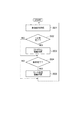
 information collecting device 200 executes steps S45 and S46. In step S45, the list screen generation unit 214 generates list screen data based on the data extracted for each job program. In step S46, the list screen generation unit 214 outputs the data of the list screen to the display device or the like. This completes the procedure for generating the list screen. By this procedure, for example, the list screen of FIG. 8 is displayed.

(経時変化画面の生成手順)
図19に示すように、情報収集装置200は、まずステップS51,S52,S53を実行する。ステップS51では、経時変化画面生成部216が、上述した追跡対象の評価情報のうち、最新の評価情報を評価結果データベース225から抽出する。ステップS52では、経時変化画面生成部216が、追跡対象の評価情報のうち、直前に抽出した評価情報よりも一つ古い評価情報を評価結果データベース225から抽出する。ステップS53では、経時変化画面生成部216が、予め設定された表示対象期間の評価情報の抽出が完了したかを確認する。
(Procedure for generating a screen that changes over time)
As shown in FIG. 19, the information collecting device 200 first executes steps S51, S52, and S53. In step S51, the time-dependent change screen generation unit 216 extracts the latest evaluation information from the evaluation result database 225 from the above-mentioned evaluation information of the tracking target. In step S52, the time-dependent change screen generation unit 216 extracts from the evaluation result database 225 the evaluation information one older than the evaluation information extracted immediately before among the evaluation information of the tracking target. In step S53, the time-dependent change screen generation unit 216 confirms whether or not the extraction of the evaluation information of the preset display target period has been completed.

ステップS53において表示対象期間の評価情報の抽出が完了していないと判定した場合、情報収集装置200は処理をステップS52に戻す。以後、上記表示対象期間の評価情報の抽出が完了するまで、過去の評価情報の抽出が繰り返される。 When it is determined in step S53 that the extraction of the evaluation information of the display target period is not completed, the information collecting device 200 returns the process to step S52. After that, the extraction of the past evaluation information is repeated until the extraction of the evaluation information of the display target period is completed.

ステップS53において表示対象期間の評価情報の抽出が完了したと判定した場合、情報収集装置200はステップS54,S55を実行する。ステップS54では、経時変化画面生成部216が、抽出した複数の評価情報の経時変化画面のデータを生成する。ステップS55では、経時変化画面生成部216が、経時変化画面のデータを表示デバイス等に出力する。以上で経時変化画面の生成手順が完了する。この手順によって、例えば図11の経時変化画面が表示される。 When it is determined in step S53 that the extraction of the evaluation information of the display target period is completed, the information collecting device 200 executes steps S54 and S55. In step S54, the time-dependent change screen generation unit 216 generates data of the time-dependent change screen of the plurality of extracted evaluation information. In step S55, the time-dependent change screen generation unit 216 outputs the data of the time-dependent change screen to the display device or the like. This completes the procedure for generating the time-dependent screen. By this procedure, for example, the time-dependent change screen of FIG. 11 is displayed.

(信号チャート画面の生成手順)
図20に示すように、情報収集装置200は、ステップS61,S62,S63を実行する。ステップS61では、信号チャート生成部217が、ユーザにより指定された期間における制御信号を制御信号データベース223から抽出する。ステップS62では、信号チャート生成部217が、抽出した制御信号の信号チャート画面のデータを生成する。ステップS63では、信号チャート生成部217が、信号チャート画面のデータを表示デバイス等に出力する。以上で信号チャート画面の生成手順が完了する。この手順によって、例えば図12の信号チャート画面が表示される。
(Procedure for generating signal chart screen)
As shown in FIG. 20, the information collecting device 200 executes steps S61, S62, and S63. In step S61, the signal chart generation unit 217 extracts the control signal in the period specified by the user from the control signal database 223. In step S62, the signal chart generation unit 217 generates the data of the signal chart screen of the extracted control signal. In step S63, the signal chart generation unit 217 outputs the data of the signal chart screen to the display device or the like. This completes the procedure for generating the signal chart screen. By this procedure, for example, the signal chart screen of FIG. 12 is displayed.

〔本実施形態の効果〕
以上に説明したように、生産システム1の情報収集装置200は、モータを含むローカル機器2の、複数の工程を含む動作時の内部情報である制御信号を、データベースに蓄積するデータハンドリング部211と、データベースに蓄積された制御信号から複数の工程のいずれか1工程の実行中に蓄積された信号セットを抽出する制御信号抽出部212と、制御信号抽出部212が抽出した信号セットを評価して、その評価結果を表す評価情報を生成する制御信号評価部213と、を備える。
[Effect of this embodiment]
As described above, the information collecting device 200 of the production system 1 has the data handling unit 211 that stores the control signal which is the internal information of the local device 2 including the motor during the operation including the plurality of processes in the database. , Evaluate the control signal extraction unit 212 that extracts the signal set accumulated during the execution of any one of the plurality of processes from the control signals stored in the database, and the signal set extracted by the control signal extraction unit 212. , A control signal evaluation unit 213 that generates evaluation information representing the evaluation result.

この情報収集装置200によれば、制御信号の評価と評価情報の蓄積とを工程単位で実行することができる。工程単位で蓄積された評価情報によれば、例えば同一工程同士で評価情報を容易に比較することができる。従って、ローカル機器のコンディションの早期把握に有効である。 According to the information collecting device 200, the evaluation of the control signal and the accumulation of the evaluation information can be executed on a process-by-process basis. According to the evaluation information accumulated in each process, for example, the evaluation information can be easily compared between the same processes. Therefore, it is effective for early grasping the condition of the local device.

データハンドリング部211は、ローカル機器2の動作時刻に関する時間情報を、データベースに更に蓄積し、制御信号抽出部212は、時間情報に基づいて、信号セットを抽出してもよい。この場合、時間情報に基づくことで、信号セットを容易且つ適切に抽出することができる。 The data handling unit 211 may further store time information regarding the operating time of the local device 2 in the database, and the control signal extraction unit 212 may extract the signal set based on the time information. In this case, the signal set can be easily and appropriately extracted based on the time information.

データハンドリング部211は、ローカル機器2を動作させるプログラムに関するプログラム情報を、データベースに更に蓄積し、制御信号抽出部212は、プログラム情報に基づいて、信号セットを抽出してもよい。この場合、ローカル機器2の動作を定めるプログラム情報に基づくことで、信号セットを容易且つ適切に抽出することができる。 The data handling unit 211 may further store the program information regarding the program for operating the local device 2 in the database, and the control signal extraction unit 212 may extract the signal set based on the program information. In this case, the signal set can be easily and appropriately extracted based on the program information that determines the operation of the local device 2.

データハンドリング部211は、ローカル機器2により生産されるワーク9に関するワーク情報を、データベースに蓄積し、制御信号抽出部212は、ワーク情報に基づいて、信号セットを抽出してもよい。この場合、ワーク情報に基づくことで、1つのワーク9に対応する工程の信号データを容易且つ適切に抽出することができる。
制御信号評価部213は、信号セットが入力されると評価情報を出力する複数種類の評価エンジン231のいずれか1つを、信号セットの抽出条件に基づいて選択し、信号セットと、選択した評価エンジン231とに基づいて評価情報を生成してもよい。この場合、例えばローカル機器2の動作内容に応じて複数種類の評価エンジン231を使い分けることによって、信号セットをより適切に評価することができる。
The data handling unit 211 may store work information about the work 9 produced by the local device 2 in a database, and the control signal extraction unit 212 may extract a signal set based on the work information. In this case, the signal data of the process corresponding to one work 9 can be easily and appropriately extracted based on the work information.
The control signal evaluation unit 213 selects one of a plurality of types of evaluation engines 231 that output evaluation information when a signal set is input based on the extraction conditions of the signal set, and sets the signal and the selected evaluation. Evaluation information may be generated based on the engine 231 and the like. In this case, for example, the signal set can be evaluated more appropriately by properly using a plurality of types of evaluation engines 231 according to the operation content of the local device 2.

制御信号抽出部212は、同一の工程を指定する抽出条件に基づいて信号セットを繰り返し抽出し、制御信号評価部213は、制御信号抽出部212により抽出された評価対象の信号セットと、過去に制御信号抽出部212により抽出された少なくとも一つの比較対象の信号セットとに基づいて評価対象の信号セットの評価情報を生成してもよい。この場合、過去の同一工程の信号セットとの比較によって信号セットを評価することによって、当該信号セットの異常度をより高い信頼性で評価することができる。 The control signal extraction unit 212 repeatedly extracts the signal set based on the extraction conditions that specify the same process, and the control signal evaluation unit 213 includes the signal set to be evaluated extracted by the control signal extraction unit 212 and the signal set to be evaluated in the past. Evaluation information of the signal set to be evaluated may be generated based on at least one signal set to be compared extracted by the control signal extraction unit 212. In this case, the degree of abnormality of the signal set can be evaluated with higher reliability by evaluating the signal set by comparing with the signal set of the same process in the past.

制御信号抽出部212は、同一の工程を指定する抽出条件に基づいて信号セットを繰り返し抽出し、制御信号評価部213は、制御信号抽出部212が繰り返し抽出した複数の信号セットを評価し、その評価結果をそれぞれ表す複数の評価情報を生成してデータベースに蓄積し、生産システム1の情報収集装置200は、データベースに蓄積された複数の評価情報に基づいて、評価情報の経時変化を表す経時変化画面を生成する経時変化画面生成部216を更に備えていてもよい。この場合、評価情報の経時変化の表示によって、評価情報の早期把握を更に図ることができる。 The control signal extraction unit 212 repeatedly extracts a signal set based on extraction conditions that specify the same process, and the control signal evaluation unit 213 evaluates a plurality of signal sets repeatedly extracted by the control signal extraction unit 212, and evaluates the plurality of signal sets. A plurality of evaluation information representing each evaluation result is generated and stored in a database, and the information collecting device 200 of the production system 1 represents a time-dependent change of the evaluation information based on the plurality of evaluation information stored in the database. A time-varying screen generation unit 216 that generates a screen may be further provided. In this case, it is possible to further grasp the evaluation information at an early stage by displaying the change with time of the evaluation information.

データハンドリング部211は、複数の工程を、一まとまりの作業に属する2以上の工程ごとにグルーピングするグルーピング情報をデータベースに更に蓄積し、制御信号抽出部212は、グルーピング情報に基づいて、同一グループに属する2以上の工程にそれぞれ対応する2以上の信号セットを同一グループの信号セットとして抽出し、制御信号評価部213は、同一グループの信号セットのそれぞれを評価して評価情報をデータベースに蓄積し、生産システム1の情報収集装置200は、データベースに蓄積された、同一グループの信号セットの評価情報に基づいて、当該グループに対応するローカル機器の動作の評価結果を表す動作評価情報を生成する動作評価部215と、動作評価情報をグループごとに表示する一覧画面を生成する一覧画面生成部214と、を更に備えていてもよい。この場合、各グループにおける2以上の工程の評価情報を、一つの動作評価情報にまとめることで、ローカル機器2のコンディションの概況を把握しやすい一覧画面を表示することができる。 The data handling unit 211 further accumulates grouping information in the database for grouping a plurality of processes for each of two or more processes belonging to a group of operations, and the control signal extraction unit 212 groups the plurality of processes in the same group based on the grouping information. Two or more signal sets corresponding to each of the two or more processes to which they belong are extracted as signal sets of the same group, and the control signal evaluation unit 213 evaluates each of the signal sets of the same group and stores the evaluation information in the database. The information collecting device 200 of the production system 1 generates an operation evaluation information representing an operation evaluation result of a local device corresponding to the group based on the evaluation information of the signal set of the same group accumulated in the database. A unit 215 and a list screen generation unit 214 for generating a list screen for displaying operation evaluation information for each group may be further provided. In this case, by combining the evaluation information of the two or more processes in each group into one operation evaluation information, it is possible to display a list screen that makes it easy to grasp the general condition of the condition of the local device 2.

データハンドリング部211は、複数の工程を、一まとまりの作業に属する2以上の工程ごとにグルーピングするグルーピング情報をデータベースに更に蓄積し、制御信号抽出部212は、グルーピング情報に基づいて、同一グループに属する2以上の工程にそれぞれ対応する2以上の信号セットを同一グループの信号セットとして抽出し、制御信号評価部213は、同一グループの信号セットのそれぞれを評価して評価情報をデータベースに蓄積し、生産システム1の情報収集装置200は、データベースに蓄積された、同一グループの信号セットのそれぞれの評価情報をグループごとに表示する一覧画面を生成する一覧画面生成部214を更に備えていてもよい。この場合、複数の工程の評価情報を、一まとまりの作業ごとにグルーピングすることによって、評価情報を把握すべき工程を発見し易い一覧画面を表示することができる。 The data handling unit 211 further accumulates grouping information in the database for grouping a plurality of processes for each of two or more processes belonging to a group of operations, and the control signal extraction unit 212 groups the plurality of processes in the same group based on the grouping information. Two or more signal sets corresponding to each of the two or more processes to which they belong are extracted as signal sets of the same group, and the control signal evaluation unit 213 evaluates each of the signal sets of the same group and stores the evaluation information in the database. The information collecting device 200 of the production system 1 may further include a list screen generation unit 214 that generates a list screen that displays the evaluation information of each signal set of the same group stored in the database for each group. In this case, by grouping the evaluation information of a plurality of processes for each group of operations, it is possible to display a list screen that makes it easy to find the process for which the evaluation information should be grasped.

データハンドリング部211は、2以上の工程を含むローカル機器2の動作により生産されるワーク9に関するワーク情報を含むグルーピング情報をデータベースに蓄積し、制御信号抽出部212は、少なくともワーク情報に基づいて、同一ワークに対する2以上の工程にそれぞれ対応する2以上の信号セットを、同一グループの信号セットとして抽出してもよい。この場合、ワーク情報に基づくことによって、より適切なグルーピングが可能となる。 The data handling unit 211 stores grouping information including work information about the work 9 produced by the operation of the local device 2 including two or more steps in the database, and the control signal extraction unit 212 at least based on the work information. Two or more signal sets corresponding to two or more steps for the same work may be extracted as a signal set of the same group. In this case, more appropriate grouping becomes possible by being based on the work information.

データハンドリング部211は、ワーク9の品質の検査結果を表す品質情報をデータベースに更に蓄積し、一覧画面生成部214は、品質情報をワークごとに表示する品質一覧画面を更に生成してもよい。この場合、品質一覧画面を更に生成することによって、評価情報を把握すべき工程の発見が更に容易となる。 The data handling unit 211 may further accumulate quality information representing the quality inspection result of the work 9 in the database, and the list screen generation unit 214 may further generate a quality list screen that displays the quality information for each work. In this case, by further generating the quality list screen, it becomes easier to find the process for which the evaluation information should be grasped.

データハンドリング部211は、ローカル機器2の2以上の工程を含む複数のジョブプログラムに関するジョブ情報を含むグルーピング情報をデータベースに蓄積し、制御信号抽出部212は、少なくともジョブ情報に基づいて、同一ジョブプログラムに属する2以上の工程にそれぞれ対応する2以上の信号セットを、同一グループの信号セットとして抽出してもよい。この場合、ジョブ情報に更に基づくことによって、より適切なグルーピングが可能となる。 The data handling unit 211 stores grouping information including job information related to a plurality of job programs including two or more processes of the local device 2 in the database, and the control signal extraction unit 212 stores the same job program based on at least the job information. Two or more signal sets corresponding to each of the two or more steps belonging to may be extracted as a signal set of the same group. In this case, more appropriate grouping becomes possible by further based on the job information.

以上、実施形態について説明したが、本開示は必ずしも上述した実施形態に限定されるものではなく、その要旨を逸脱しない範囲で様々な変更が可能である。 Although the embodiments have been described above, the present disclosure is not necessarily limited to the above-described embodiments, and various changes can be made without departing from the gist thereof.

1…生産システム、2…ローカル機器、9…ワーク、200…情報収集装置、211…データハンドリング部、212…制御信号抽出部、213…制御信号評価部、214…一覧画面生成部、215…動作評価部、216…経時変化画面生成部、231…評価エンジン。 1 ... Production system, 2 ... Local equipment, 9 ... Work, 200 ... Information collection device, 211 ... Data handling unit, 212 ... Control signal extraction unit, 213 ... Control signal evaluation unit, 214 ... List screen generation unit, 215 ... Operation Evaluation unit, 216 ... Time-varying screen generation unit, 231 ... Evaluation engine.

Claims (14)

モータを含むローカル機器の、複数の工程を含む動作時の内部情報である制御信号を、データベースに蓄積するデータハンドリング部と、
前記データベースに蓄積された制御信号から複数の工程のいずれか1工程の実行中に蓄積された信号セットを抽出する制御信号抽出部と、
前記制御信号抽出部が抽出した前記信号セットを評価して、その評価結果を表す評価情報を生成する制御信号評価部と、を備える生産システムの情報収集装置。
A data handling unit that stores control signals, which are internal information during operation of local equipment including motors, including multiple processes, in a database.
A control signal extraction unit that extracts a signal set accumulated during the execution of any one of a plurality of steps from the control signals stored in the database, and a control signal extraction unit.
An information collecting device for a production system including a control signal evaluation unit that evaluates the signal set extracted by the control signal extraction unit and generates evaluation information representing the evaluation result.
前記データハンドリング部は、前記ローカル機器の動作時刻に関する時間情報を、前記データベースに更に蓄積し、
前記制御信号抽出部は、前記時間情報に基づいて、前記信号セットを抽出する、請求項1記載の生産システムの情報収集装置。
The data handling unit further accumulates time information regarding the operating time of the local device in the database.
The information collecting device of the production system according to claim 1, wherein the control signal extraction unit extracts the signal set based on the time information.
前記データハンドリング部は、前記ローカル機器を動作させるプログラムに関するプログラム情報を、前記データベースに更に蓄積し、
前記制御信号抽出部は、前記プログラム情報に基づいて、前記信号セットを抽出する、請求項1又は2記載の生産システムの情報収集装置。
The data handling unit further accumulates program information regarding a program for operating the local device in the database.
The information collecting device of the production system according to claim 1 or 2, wherein the control signal extraction unit extracts the signal set based on the program information.
前記データハンドリング部は、前記ローカル機器により生産されるワークに関するワーク情報を、前記データベースに蓄積し、
前記制御信号抽出部は、前記ワーク情報に基づいて、前記信号セットを抽出する、請求項1〜3のいずれか一項記載の生産システムの情報収集装置。
The data handling unit stores work information about the work produced by the local device in the database.
The information collecting device for a production system according to any one of claims 1 to 3, wherein the control signal extraction unit extracts the signal set based on the work information.
前記制御信号評価部は、
前記信号セットが入力されると前記評価情報を出力する複数種類の評価エンジンのいずれか1つを、前記信号セットの抽出条件に基づいて選択し、
前記信号セットと、選択した評価エンジンとに基づいて前記評価情報を生成する、請求項1〜4のいずれか一項記載の生産システムの情報収集装置。
The control signal evaluation unit
One of a plurality of types of evaluation engines that outputs the evaluation information when the signal set is input is selected based on the extraction conditions of the signal set.
The information gathering device for a production system according to any one of claims 1 to 4, which generates the evaluation information based on the signal set and the selected evaluation engine.
前記制御信号抽出部は、同一の工程を指定する抽出条件に基づいて信号セットを繰り返し抽出し、
前記制御信号評価部は、前記制御信号抽出部により抽出された評価対象の信号セットと、過去に前記制御信号抽出部により抽出された少なくとも一つの比較対象の信号セットとに基づいて前記評価対象の信号セットの前記評価情報を生成する、請求項1〜5のいずれか一項記載の生産システムの情報収集装置。
The control signal extraction unit repeatedly extracts a signal set based on extraction conditions that specify the same process, and then extracts the signal set repeatedly.
The control signal evaluation unit is based on the signal set of the evaluation target extracted by the control signal extraction unit and at least one comparison target signal set extracted by the control signal extraction unit in the past. The information collecting device for a production system according to any one of claims 1 to 5, which generates the evaluation information of the signal set.
前記制御信号抽出部は、同一の工程を指定する抽出条件に基づいて信号セットを繰り返し抽出し、
前記制御信号評価部は、前記制御信号抽出部が繰り返し抽出した複数の信号セットを評価し、その評価結果をそれぞれ表す複数の評価情報を生成して前記データベースに蓄積し、
生産システムの情報収集装置は、
前記データベースに蓄積された複数の評価情報に基づいて、評価情報の経時変化を表す経時変化画面を生成する経時変化画面生成部を更に備える、請求項6記載の生産システムの情報収集装置。
The control signal extraction unit repeatedly extracts a signal set based on extraction conditions that specify the same process, and then extracts the signal set repeatedly.
The control signal evaluation unit evaluates a plurality of signal sets repeatedly extracted by the control signal extraction unit, generates a plurality of evaluation information representing the evaluation results, and stores them in the database.
The information gathering device of the production system is
The information collecting device for a production system according to claim 6, further comprising a time-varying screen generation unit that generates a time-varying screen showing a time-dependent change of evaluation information based on a plurality of evaluation information stored in the database.
前記データハンドリング部は、前記複数の工程を、一まとまりの作業に属する2以上の工程ごとにグルーピングするグルーピング情報を前記データベースに更に蓄積し、
前記制御信号抽出部は、前記グルーピング情報に基づいて、同一グループに属する前記2以上の工程にそれぞれ対応する2以上の信号セットを同一グループの信号セットとして抽出し、
前記制御信号評価部は、前記同一グループの信号セットのそれぞれを評価して前記評価情報をデータベースに蓄積し、
生産システムの情報収集装置は、
前記データベースに蓄積された、前記同一グループの信号セットの前記評価情報に基づいて、当該グループに対応する前記ローカル機器の動作の評価結果を表す動作評価情報を生成する動作評価部と、
前記動作評価情報をグループごとに表示する一覧画面を生成する一覧画面生成部と、を更に備える、請求項1記載の生産システムの情報収集装置。
The data handling unit further accumulates grouping information in the database for grouping the plurality of processes into two or more processes belonging to a group of operations.
Based on the grouping information, the control signal extraction unit extracts two or more signal sets corresponding to the two or more steps belonging to the same group as signal sets of the same group.
The control signal evaluation unit evaluates each of the signal sets of the same group and accumulates the evaluation information in the database.
The information gathering device of the production system is
Based on the evaluation information of the signal set of the same group accumulated in the database, an operation evaluation unit that generates operation evaluation information representing the operation evaluation result of the local device corresponding to the group, and an operation evaluation unit.
The information collecting device for a production system according to claim 1, further comprising a list screen generation unit that generates a list screen that displays the operation evaluation information for each group.
前記データハンドリング部は、前記複数の工程を、一まとまりの作業に属する2以上の工程ごとにグルーピングするグルーピング情報を前記データベースに更に蓄積し、
前記制御信号抽出部は、前記グルーピング情報に基づいて、同一グループに属する前記2以上の工程にそれぞれ対応する2以上の信号セットを同一グループの信号セットとして抽出し、
前記制御信号評価部は、前記同一グループの信号セットのそれぞれを評価して前記評価情報を前記データベースに蓄積し、
生産システムの情報収集装置は、
前記データベースに蓄積された、前記同一グループの信号セットのそれぞれの評価情報をグループごとに表示する一覧画面を生成する一覧画面生成部を更に備える、請求項1記載の生産システムの情報収集装置。
The data handling unit further accumulates grouping information in the database for grouping the plurality of processes into two or more processes belonging to a group of operations.
Based on the grouping information, the control signal extraction unit extracts two or more signal sets corresponding to the two or more steps belonging to the same group as signal sets of the same group.
The control signal evaluation unit evaluates each of the signal sets of the same group and stores the evaluation information in the database.
The information gathering device of the production system is
The information collecting device for a production system according to claim 1, further comprising a list screen generation unit that generates a list screen for displaying each evaluation information of the signal sets of the same group stored in the database for each group.
前記データハンドリング部は、2以上の工程を含む前記ローカル機器の動作により生産されるワークに関するワーク情報を含む前記グルーピング情報を前記データベースに蓄積し、
前記制御信号抽出部は、少なくとも前記ワーク情報に基づいて、同一ワークに対する2以上の工程にそれぞれ対応する2以上の信号セットを、前記同一グループの信号セットとして抽出する、請求項8又は9記載の生産システムの情報収集装置。
The data handling unit stores the grouping information including the work information about the work produced by the operation of the local device including two or more steps in the database.
8. Information gathering device for production systems.
前記データハンドリング部は、前記ワークの品質の検査結果を表す品質情報を前記データベースに更に蓄積し、
前記一覧画面生成部は、前記品質情報をワークごとに表示する品質一覧画面を更に生成する、請求項10記載の生産システムの情報収集装置。
The data handling unit further accumulates quality information representing the inspection result of the quality of the work in the database, and further accumulates the quality information.
The information collecting device of the production system according to claim 10, wherein the list screen generation unit further generates a quality list screen that displays the quality information for each work.
前記データハンドリング部は、前記ローカル機器の2以上の工程を含む複数のジョブプログラムに関するジョブ情報を含む前記グルーピング情報を前記データベースに蓄積し、
前記制御信号抽出部は、少なくとも前記ジョブ情報に基づいて、同一ジョブプログラムに属する前記2以上の工程にそれぞれ対応する2以上の信号セットを、前記同一グループの信号セットとして抽出する、請求項8〜10のいずれか一項記載の生産システムの情報収集装置。
The data handling unit stores the grouping information including job information related to a plurality of job programs including two or more steps of the local device in the database.
The control signal extraction unit extracts two or more signal sets corresponding to the two or more steps belonging to the same job program as the signal set of the same group based on at least the job information. The information collecting device for the production system according to any one of 10.
モータを含むローカル機器の、複数の工程を含む動作時の内部情報である制御信号を、データベースに蓄積することと、
前記データベースに蓄積された制御信号から複数の工程のいずれか1工程の実行中に蓄積された信号セットを抽出することと、
抽出した前記信号セットを評価して、その評価結果を表す評価情報を生成することと、を含む情報収集方法。
By accumulating control signals, which are internal information of local equipment including motors during operation including multiple processes, in a database,
Extracting the signal set accumulated during the execution of any one of a plurality of steps from the control signals stored in the database, and
An information collection method including evaluating the extracted signal set and generating evaluation information representing the evaluation result.
モータを含むローカル機器の、複数の工程を含む動作時の内部情報である制御信号を、データベースに蓄積することと、
前記データベースに蓄積された制御信号から複数の工程のいずれか1工程の実行中に蓄積された信号セットを抽出することと、
抽出した前記信号セットを評価して、その評価結果を表す評価情報を生成することと、を装置に実行させるプログラム。
By accumulating control signals, which are internal information of local equipment including motors during operation including multiple processes, in a database,
Extracting the signal set accumulated during the execution of any one of a plurality of steps from the control signals stored in the database, and
A program that causes an apparatus to evaluate the extracted signal set and generate evaluation information representing the evaluation result.
JP2021519174A 2019-11-27 2019-11-27 Information collection equipment, information collection methods and programs for production systems Active JP6965477B2 (en)

Priority Applications (1)

Application Number Priority Date Filing Date Title
JP2021171963A JP7407784B2 (en) 2019-11-27 2021-10-20 Production system information gathering device, information gathering method and program

Applications Claiming Priority (1)

Application Number Priority Date Filing Date Title
PCT/JP2019/046456 WO2021106117A1 (en) 2019-11-27 2019-11-27 Production system information collection device, information collection method, and program

Related Child Applications (1)

Application Number Title Priority Date Filing Date
JP2021171963A Division JP7407784B2 (en) 2019-11-27 2021-10-20 Production system information gathering device, information gathering method and program

Publications (2)

Publication Number Publication Date
JP6965477B2 true JP6965477B2 (en) 2021-11-10
JPWO2021106117A1 JPWO2021106117A1 (en) 2021-12-02

Family

ID=76130404

Family Applications (2)

Application Number Title Priority Date Filing Date
JP2021519174A Active JP6965477B2 (en) 2019-11-27 2019-11-27 Information collection equipment, information collection methods and programs for production systems
JP2021171963A Active JP7407784B2 (en) 2019-11-27 2021-10-20 Production system information gathering device, information gathering method and program

Family Applications After (1)

Application Number Title Priority Date Filing Date
JP2021171963A Active JP7407784B2 (en) 2019-11-27 2021-10-20 Production system information gathering device, information gathering method and program

Country Status (6)

Country Link
US (1) US20220291670A1 (en)
EP (1) EP4068023A4 (en)
JP (2) JP6965477B2 (en)
CN (1) CN114730179A (en)
TW (1) TW202138946A (en)
WO (1) WO2021106117A1 (en)

Cited By (2)

* Cited by examiner, † Cited by third party
Publication number Priority date Publication date Assignee Title
EP4254104A1 (en) * 2022-04-01 2023-10-04 OMRON Corporation Device and program for collecting data
EP4254106A1 (en) * 2022-04-01 2023-10-04 OMRON Corporation Device, system, method, and program for collecting data

Family Cites Families (10)

* Cited by examiner, † Cited by third party
Publication number Priority date Publication date Assignee Title
JP3153094B2 (en) * 1995-03-01 2001-04-03 三菱電機株式会社 Manufacturing process control device
JP2002117107A (en) * 1999-09-02 2002-04-19 Ricoh Co Ltd Production managing system, client for the same, production managing method for the same, data retrieving method for the same and computer readable recording medium stored with program for executing the same method
JP4495960B2 (en) * 2003-12-26 2010-07-07 キヤノンItソリューションズ株式会社 Model creation device for the relationship between process and quality
JP5177958B2 (en) * 2006-03-31 2013-04-10 Hoya株式会社 Processing data management system, processing system for magnetic disk manufacturing apparatus, and data management method for magnetic disk manufacturing apparatus
US7962440B2 (en) * 2007-09-27 2011-06-14 Rockwell Automation Technologies, Inc. Adaptive industrial systems via embedded historian data
JP2009169458A (en) * 2008-01-10 2009-07-30 Sharp Corp Production process management system
JP2010198447A (en) 2009-02-26 2010-09-09 Canon Inc Production facility trouble treatment history collecting device
JP2019036075A (en) 2017-08-11 2019-03-07 株式会社ジェイテクト Data processing device of production facility
JP7151108B2 (en) * 2018-03-15 2022-10-12 株式会社リコー Information processing device, information processing method and program
JP7358755B2 (en) 2019-03-15 2023-10-11 株式会社リコー Diagnostic device, diagnostic method, and diagnostic program

Cited By (2)

* Cited by examiner, † Cited by third party
Publication number Priority date Publication date Assignee Title
EP4254104A1 (en) * 2022-04-01 2023-10-04 OMRON Corporation Device and program for collecting data
EP4254106A1 (en) * 2022-04-01 2023-10-04 OMRON Corporation Device, system, method, and program for collecting data

Also Published As

Publication number Publication date
EP4068023A4 (en) 2023-08-09
TW202138946A (en) 2021-10-16
WO2021106117A1 (en) 2021-06-03
JP7407784B2 (en) 2024-01-04
EP4068023A1 (en) 2022-10-05
CN114730179A (en) 2022-07-08
JP2022009322A (en) 2022-01-14
US20220291670A1 (en) 2022-09-15
JPWO2021106117A1 (en) 2021-12-02

Similar Documents

Publication Publication Date Title
CN113110328B (en) Production process full-period intelligent workshop system based on digital twin technology and solution method
US20220291670A1 (en) Control data extraction and evaluation of production system
JP6348137B2 (en) Machining machine system for judging the quality of workpieces
EP3579100A1 (en) Apparatus and method for skill-based robot programming
CN105382840B (en) The control device and control method of robot
US20220001537A1 (en) Control system, robot system and control method
KR102525831B1 (en) Control system, controller and control method
CN117021082A (en) Control device and non-transitory computer readable medium
CN110303491A (en) Act history management system
CN105710880B (en) Robot safe, with track advance variable
US20230107431A1 (en) Comparison between real control and virtual control of robot
Bhatt et al. Trajectory-dependent compensation scheme to reduce manipulator execution errors for manufacturing applications
JP7374867B2 (en) Control system, local controller and control method
Linnerud et al. CAD-based system for programming of robotic assembly processes with human-in-the-loop
US20210129331A1 (en) Control method, control apparatus, robot apparatus, method of manufacturing an article, motion program creation method, motion program creation apparatus, display apparatus, and control program recording medium
JP6577686B1 (en) Control device, work robot, program, and control method
WO2023167324A1 (en) Production system and reproduction method
Putri et al. The prototype of arm robot for object mover using Arduino Mega 2560
Kovarikova et al. Prototyping an intelligent robotic welding workplace by a cyber-physic tool
WO2023157889A1 (en) Production system and production method
JPH10260713A (en) Controller for production facility
JP6731603B1 (en) Inspection system
Neumann et al. An automated pick-and-place benchmarking system in robotics
Shah Automatic Welding and Soldering Machine Using PLC in Automobile Application
JP2022002043A (en) Facility monitoring system

Legal Events

Date Code Title Description
A621 Written request for application examination

Free format text: JAPANESE INTERMEDIATE CODE: A621

Effective date: 20210428

A871 Explanation of circumstances concerning accelerated examination

Free format text: JAPANESE INTERMEDIATE CODE: A871

Effective date: 20210428

TRDD Decision of grant or rejection written
A01 Written decision to grant a patent or to grant a registration (utility model)

Free format text: JAPANESE INTERMEDIATE CODE: A01

Effective date: 20210921

A61 First payment of annual fees (during grant procedure)

Free format text: JAPANESE INTERMEDIATE CODE: A61

Effective date: 20211020

R150 Certificate of patent or registration of utility model

Ref document number: 6965477

Country of ref document: JP

Free format text: JAPANESE INTERMEDIATE CODE: R150