JP6965132B2 - Image processing equipment, imaging equipment, image processing methods and programs - Google Patents
Image processing equipment, imaging equipment, image processing methods and programs Download PDFInfo
- Publication number
- JP6965132B2 JP6965132B2 JP2017233592A JP2017233592A JP6965132B2 JP 6965132 B2 JP6965132 B2 JP 6965132B2 JP 2017233592 A JP2017233592 A JP 2017233592A JP 2017233592 A JP2017233592 A JP 2017233592A JP 6965132 B2 JP6965132 B2 JP 6965132B2
- Authority
- JP
- Japan
- Prior art keywords
- image
- image processing
- processing apparatus
- luminance
- correction
- Prior art date
- Legal status (The legal status is an assumption and is not a legal conclusion. Google has not performed a legal analysis and makes no representation as to the accuracy of the status listed.)
- Active
Links
Images


Classifications
-
- H—ELECTRICITY
- H04—ELECTRIC COMMUNICATION TECHNIQUE
- H04N—PICTORIAL COMMUNICATION, e.g. TELEVISION
- H04N5/00—Details of television systems
- H04N5/222—Studio circuitry; Studio devices; Studio equipment
- H04N5/262—Studio circuits, e.g. for mixing, switching-over, change of character of image, other special effects ; Cameras specially adapted for the electronic generation of special effects
- H04N5/2621—Cameras specially adapted for the electronic generation of special effects during image pickup, e.g. digital cameras, camcorders, video cameras having integrated special effects capability
-
- H—ELECTRICITY
- H04—ELECTRIC COMMUNICATION TECHNIQUE
- H04N—PICTORIAL COMMUNICATION, e.g. TELEVISION
- H04N23/00—Cameras or camera modules comprising electronic image sensors; Control thereof
- H04N23/70—Circuitry for compensating brightness variation in the scene
- H04N23/71—Circuitry for evaluating the brightness variation
-
- H—ELECTRICITY
- H04—ELECTRIC COMMUNICATION TECHNIQUE
- H04N—PICTORIAL COMMUNICATION, e.g. TELEVISION
- H04N23/00—Cameras or camera modules comprising electronic image sensors; Control thereof
- H04N23/80—Camera processing pipelines; Components thereof
-
- H—ELECTRICITY
- H04—ELECTRIC COMMUNICATION TECHNIQUE
- H04N—PICTORIAL COMMUNICATION, e.g. TELEVISION
- H04N9/00—Details of colour television systems
- H04N9/64—Circuits for processing colour signals
- H04N9/646—Circuits for processing colour signals for image enhancement, e.g. vertical detail restoration, cross-colour elimination, contour correction, chrominance trapping filters
Description
本発明は、画像処理装置、撮像装置、画像処理方法およびプログラムに関し、特に、撮影画像を用いて動画を生成する画像処理装置、撮像装置、画像処理方法およびプログラムに関するものである。 The present invention relates to an image processing device, an imaging device, an image processing method and a program, and more particularly to an image processing device, an imaging device, an image processing method and a program for generating a moving image using a captured image.
画像映像表現の一手法として、シーンの雰囲気を活かした特殊な効果を持った動画を生成する技術が求められている。 As a method of image-video expression, a technique for generating a moving image having a special effect utilizing the atmosphere of a scene is required.
例えば、このような動画として、画像における一部の領域のみが変化するシネマグラフという動画が知られている。シネマグラフを生成する場合、変化を与える領域と変化を与えない領域を指定する必要があるなど、撮影画像を編集する必要があるため、ユーザの負荷が大きかった。 For example, as such a moving image, a moving image called a cinemagraph in which only a part of an area in an image changes is known. When generating a cinemagraph, it is necessary to edit the captured image, for example, it is necessary to specify an area where the change is given and an area where the change is not given, which imposes a heavy load on the user.
また、上記技術として、光が輝いているアニメーション効果を画像に対して自動的に付加する技術が知られている。しかし、このような技術を用いた場合、画像上での光の光り方が不自然な動画になる場合があった。 Further, as the above technique, a technique for automatically adding an animation effect of shining light to an image is known. However, when such a technique is used, the way the light shines on the image may become an unnatural moving image.
したがって、ユーザの負荷を抑えながら、画像の一部の領域のみに変化を与え、特殊な効果を持った動画を生成する技術が必要となる。 Therefore, there is a need for a technique for generating a moving image having a special effect by changing only a part of the image while suppressing the load on the user.
一方、画像に対して領域毎に異なる効果を与えることにより特殊な印象を持たせたり、画像が有する雰囲気を強調させたりする技術が知られている。例えば特許文献1には、距離情報に応じて領域毎に階調補正処理を適用することで、撮像装置から遠い領域はコントラストを下げ、近い領域はコントラストを上げる技術が開示されている。これにより、画像に奥行き感をもたらすことができる。
On the other hand, there are known techniques for giving a special impression to an image by giving a different effect to each region and emphasizing the atmosphere of the image. For example,
しかしながら、特許文献1に開示の技術では、シネマグラフのように一部の被写体のみが変化するような動画において、その被写体は、撮像装置から遠い位置にあると、コントラストを上げて強調することはできないという問題がある。
However, according to the technique disclosed in
本発明は、上記課題を解決すべく、ユーザの負荷を抑えながら、シーンに適した特殊な効果を持った動画を得ることができる画像処理装置、撮像装置、画像処理方法およびプログラムを提供することを目的とする。 The present invention provides an image processing device, an imaging device, an image processing method, and a program capable of obtaining a moving image having a special effect suitable for a scene while suppressing a load on the user in order to solve the above problems. With the goal.
本発明の請求項1に係る画像処理装置は、撮影により生成された第1の画像を取得する取得手段と、前記第1の画像に含まれる前記撮影の際の各被写体の距離の分布に応じて前記第1の画像を2つ以上の領域に分割する分割手段と、前記分割された領域の1つを、高輝度な画素が存在する高輝度領域として検出する検出手段と、前記高輝度領域において、前記高輝度な画素及びその周辺画素に対し、異なる補正強度で前記第1の画像の補正を行い、複数の第2の画像を生成する第1の生成手段と、前記生成された複数の第2の画像を用いて動画を生成する第2の生成手段とを備えることを特徴とする。
The image processing apparatus according to
本発明によれば、ユーザの負荷を抑えながら、シーンに適した特殊な効果を持った動画を得ることができる。 According to the present invention, it is possible to obtain a moving image having a special effect suitable for a scene while suppressing the load on the user.
以下、図面を参照して本発明の実施例を詳細に説明する。 Hereinafter, examples of the present invention will be described in detail with reference to the drawings.
本実施例では、1枚の静止画を撮影し、得られた画像を用いてユーザの介在なく動画の生成を行う技術について説明する。なお本実施例では、最も効果が見込めるシーンの1つである夜景シーンでの撮影を想定して説明を行うが、夜景以外のシーンにおいても適用可能である。また、以下では、本実施例に係る画像処理装置の一例として撮像装置について説明するが、これに限定されず、例えばパーソナルコンピュータ(PC)などであってもよい。この場合、PCは外部の撮像装置で撮影された画像を取得するための通信手段を更に備える。 In this embodiment, a technique of capturing one still image and using the obtained image to generate a moving image without the intervention of a user will be described. In this embodiment, the description is made assuming shooting in a night scene, which is one of the most effective scenes, but it can also be applied to scenes other than night scenes. Further, although the image pickup apparatus will be described below as an example of the image processing apparatus according to the present embodiment, the present invention is not limited to this, and for example, a personal computer (PC) may be used. In this case, the PC further includes a communication means for acquiring an image taken by an external imaging device.
図1は、本発明の実施例1に係る撮像装置100のハードウェア構成を示すブロック図である。
FIG. 1 is a block diagram showing a hardware configuration of the
図1において、光学系101は、ズームレンズやフォーカスレンズから構成されるレンズ群、絞り調整装置、および、シャッター装置を備えている。この光学系101は、撮像部102に到達する被写体像の倍率やピント位置、あるいは、光量を調整している。撮像部102は、光学系101を通過した被写体の光束を光電変換し電気信号(映像信号)に変換するCCDやCMOSセンサー等の光電変換素子である。
In FIG. 1, the
A/D変換部103は、撮像部102から入力された映像信号をデジタルの画像に変換する。
The A /
画像処理部104は、通常の信号処理の他に、本発明における階調処理を行う。画像処理部104はA/D変換部103から出力された画像のみでなく、記録部107から読み出した画像に対しても同様の画像処理を行うことができる。
The
露光量制御部105は、適正な明るさを持つ入力画像を得る為の撮影時の露光量を算出し、それを実現する為に光学系101と撮像部102を制御して、絞り、シャッタースピード、センサーのアナログゲインを制御する。
The exposure
表示部106は、画像処理部104から出力される画像をLCDなどの表示用部材に逐次表示することにより、電子ビューファインダ(EVF)として機能する。
The
記録部107は、画像を記録する機能を有し、たとえば、半導体メモリが搭載されたメモリカードや光磁気ディスク等の回転記録体を収容したパッケージなどを用いた情報記録媒体を含んでもよい。
The
図3(A)は、図1の撮像部102を構成する画素302の配列構成を示している。図3(B)は画素302を拡大したものであり、マイクロレンズ301と一対の光電変換部303A,303Bから構成される。図3(A)にあるように撮像部102では画素302が二次元的に規則的に配列されている。
FIG. 3A shows an array configuration of
図2は、図1における画像処理部104のハードウェア構成を示すブロック図である。
FIG. 2 is a block diagram showing a hardware configuration of the
距離情報取得部201は、光学系101の瞳の異なる領域から到来する光束に生ずる複数の被写体像の位相差に基づいて、撮影された画像に含まれる各被写体の距離の分布を示す距離マップおよび、それに対する信頼度を示す信頼度マップを生成する。距離マップの具体的な生成方法については、例えば特開2016−9062号公報で述べられているような公知の手法を用い、画素毎に算出されたデフォーカス量を距離マップにおいて被写体距離として扱う。また、信頼度とは上述した位相差(像ずれ量)が当該領域でどの程度検出しやすいかを表す値である。信頼度マップでは、像ずれ量を検出しにくい領域で算出された被写体距離(デフォーカス量)は正確でない可能性が高いため、信頼度が低くなるようにする。像ずれ量を検出しにくい領域とは、例えば空や自動車のボディといった被写体の模様の変化が乏しい領域である。よって、このような領域が検出された場合、その領域に対し低い信頼度が信頼度マップにおいて割り当てられる。本実施例では、模様の変化が乏しいかを判定する指標として、エッジ積分値を用いる。具体的には、入力画像を複数の微小ブロックに分割し、各微小ブロック内の画素のエッジ振幅の絶対値を積分することで算出される。そして、算出したエッジ積分値と予め設定した閾値を比較し、該閾値よりも算出したエッジ積分値が小さい場合、模様の変化が乏しい領域であると判定する。入力画像の全ての微小ブロックに対し、この判定処理を行なうことで、被写体距離の分布を示す距離マップに対する信頼度マップを生成することができる。
The distance
シーン判定部202は、入力画像を撮影時に撮像装置100が取得した、明るさや色味など各種の評価値に基づいて、撮影シーンの判別を行う。評価値の取得方法については公知の技術を用いて良く、例えば特開2009−44444号公報で述べられているようなホワイトバランス制御のために算出した光源の色温度を評価値の1つである色味として取得してもよい。
The
ヒストグラム算出部203は、入力画像の全体あるいはその一部の領域における輝度や色のヒストグラムを生成する。
The
領域判定部204は、ヒストグラム算出部203が算出したヒストグラムを参照することで、入力画像から所定の領域を検出する。
The
階調補正部205は、局所的に明るさ(輝度)、色相(色)、コントラスト、彩度などを補正する技術を用いて、領域判定部204が検出した領域に対して種々の補正処理を行う。
The
動画生成部206は、階調補正部205が補正した複数の画像に対して、リサイズや符号化など種々の処理を実施した上で動画を生成する。
The moving
図4は、撮像装置100における撮影画像に対して行う動画生成処理の手順を示すフローチャートである。
FIG. 4 is a flowchart showing a procedure of moving image generation processing performed on a captured image in the
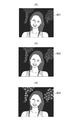
以下、図4の動画生成処理の対象となる撮影画像として、図5(A)に示す画像501が用いられる場合について説明する。画像501は、撮像装置100の撮像部102が人物を含む夜景をストロボを発光して撮影することにより取得される。
Hereinafter, a case where the
ステップS401では、シーン判定部202により画像501が示すシーンおよび光源の判定を行う。本実施例では、暗いシーン、光源はストロボ光と判定される。ここで、日中晴天などの明るいシーンと判定された場合、局所的に変化する光源が含まれる可能性は低いとして、動画を生成することなく本処理を終了する。
In step S401, the
ステップS402では、距離情報取得部201が画像501における距離マップおよび距離信頼度マップの2種の距離情報画像を生成する。図5(B)に示す画像502は、画像501に対して生成された距離マップであり、画素値が白色に近いほど撮影時における撮像装置100からの被写体距離が近いことを示している。また図5(C)に示す画像503は、画像501に対して生成された信頼度マップであり、エッジを含む人物や地面、木々などの領域は信頼度が高い白色で、無限遠の夜空や深度外でぼけている領域は信頼度が低い黒色で表されている。なお、距離マップおよび信頼度マップの解像度としてはこれに限らず、より高解像度のマップを生成するとしても良い。また距離マップとしてもデフォーカス量ではなく、複数の被写体像の位相差(像ずれ量)や、絶対距離の値に変換した値であっても良い。
In step S402, the distance
ステップS403では、ステップS402で生成した距離マップを示す画像502を、所定の閾値を用いて被写体距離の値に対してグルーピングする、すなわち2つ以上の領域(グループ)に距離マップを分割する処理を行う。閾値の設定方法としては本実施例では以下のような方法を用いる。まず、距離マップを示す画像502の領域のうち信頼度マップを示す画像503に示す信頼度の高い領域のみでヒストグラムを生成し、公知の手法によってヒストグラムを分割するのに最適な値を閾値として算出する。ここで、上記公知の手法としては、例えば、1つのグループを2つのグループに分割した時、各グループ内の分散が最小に、グループ間の分散が最大になるような閾値を最適値として探索するといった手法が挙げられる。図6は、上記方法で生成された距離マップを示す画像502のヒストグラムを示したものであり、被写体が存在する距離値に対するカウント数が大きくなっていることがわかる。本実施例においては、距離マップを示す画像502の階調数が8bitであり、また3つのグループに分けるので、結果的に36,48の2つの閾値が算出される。図5(D)に示す画像504は、算出した閾値によって図5(B)に示す画像502が3つの領域にグルーピングされた距離マップである。これを見ると、人物が含まれる領域は顔や胴体、髪の毛などの間でわずかにあった距離値の差が一つのグループとしてまとめられ、背景は木々を含む手前の領域と、無限遠を含むさらに奥の領域の3つに分けられていることがわかる。
In step S403, the
ステップS404では、ステップS403で生成した画像504のグルーピングされた領域毎に、画像501の輝度ヒストグラムを生成する。本実施例ではグルーピングされた領域の数が3つであるため、輝度ヒストグラムも3つ生成される。具体的には、図7(A)〜(C)に示すように、図5(D)に示す画像504においてグルーピングされた人物、背景(手前側)、背景(奥側)の各領域の輝度ヒストグラムが生成される。
In step S404, a luminance histogram of the
ステップS405では、ステップS404で算出した、グループ毎の輝度ヒストグラムを用いて、画像501から光源すなわち高輝度な被写体が存在する領域(高輝度領域)を検出する処理を行う。検出の仕方としては、まず、グループ毎にステップS404で算出された輝度ヒストグラムにおいて所定の輝度値(例えば8bitで224)以上を有する画素の数をカウントする。カウントされた数が所定数以上、具体的には、カウント対象のグループの領域内の総画素数の所定割合以上、例えば1割以上である場合、そのグループの領域に光源が存在し、そうでなければ存在しないと判定する。これは、高輝度である光源が存在するグループの領域には、高輝度な画素が多く存在するためである。なお、検出の方法としてはこれに限らず、高輝度だけでなく低輝度の画素も所定以上カウントする、など他の手法を用いても良い。画像502においては、図7(B)の輝度ヒストグラムが示す背景(手前側)にイルミネーションなどの光源が存在すると判定され、これによりこのグループの領域にのみ後段の階調補正を適用することが可能となる。尚、画像501をステップS405で高輝度領域に検出された領域を視認できる状態、例えばその領域を示す枠を重畳した状態で表示部106に表示すると共に、この枠内の領域に対して動画生成用の補正処理を行なう旨をユーザに通知するようにしてもよい。この通知により、ユーザは画像501を動画にする際、所望する領域が変化することになるか否かを確認することができる。
In step S405, a process of detecting a light source, that is, a region in which a high-brightness subject exists (high-luminance region) is performed from the
ステップS406では、入力された画像501においてステップS405で光源が存在すると判定されたグループの領域の距離信頼度が高い領域に、階調補正部205が階調補正を行い複数の画像を生成する。本実施例では、高輝度な画素及びその周辺に対して局所的にコントラストを補正する処理において、補正強度を3段階に変えた画像を生成する。具体的には、高輝度の画素及びこれに隣接する数画素に対する階調補正の輝度対ゲイン特性を単調変化の傾きを変えることによってコントラストの補正強度を制御する。これは、局所的なコントラストを変えることによって光の広がり具合を変化させることが目的である。図8の画像801〜803はステップS406で生成される画像であり、ステップS405で判定された背景(手前側)にいる光源の光の広がり具合に違いが各画像で異なっていることがわかる。これは、輝度対ゲイン特性の単調変化の傾きの値がステップS406で生成される画像間で異なる値となるように制御されているためである。本実施例では、図8の画像801〜803のうち、画像801におけるその傾きの値が最も大きくなるよう制御され、画像803の傾きが最も小さくなるよう制御されている。また各画像の補正において、所定の輝度値以上を有する画素(光源)からの距離が遠い画素ほど、コントラストの補正強度すなわちゲイン特性の傾きを該距離が近い画素よりも相対的に小さくする。これにより、光源から受ける光の影響度が距離に応じて変化することが実現できる。
In step S406, the
なお、本実施例ではコントラストのみを補正しているが、これに限らず明るさ(輝度)や色、彩度などを補正するようにしても良い。例えば、本実施例のような夜景シーンの場合、光源を人工照明であるイルミネーションに見立てて色をランダムに変えてもよい。このような補正を行うことによって、より夜景の雰囲気を持った変化を与えることができる。 In this embodiment, only the contrast is corrected, but the present invention is not limited to this, and the brightness (luminance), the color, the saturation, and the like may be corrected. For example, in the case of a night view scene as in this embodiment, the light source may be regarded as an illumination that is artificial lighting, and the colors may be randomly changed. By making such a correction, it is possible to give a change with a more night view atmosphere.
ステップS407において、ステップS406で生成された複数の画像を用いて動画生成部206により動画が生成され、その生成された動画が記録部107へ記録されると、本処理を終了する。本実施例の場合、階調補正前の画像501および階調補正後の画像801〜803を順に並べられ、それを所望とする動画の秒数となるまで繰り返された動画が生成される。すなわち、画像501→801→802→803→802→801→501→・・・という並び順のフレーム画像から構成される動画が生成される。なお、フレームの並び順としてはこれに限らず、ランダムとしても良い。動画のフレームレートとしては、人工照明であるイルミネーションの光が変化する間隔を想定し、5fps程度とする。生成する動画のフォーマットは特に限定されず、例えば、AVI,MPG,MotionJPEGやgifによるアニメーションなどが生成される。
In step S407, when a moving image is generated by the moving
本実施例によれば、入力画像を取得してから、画像処理部104で距離情報の取得、領域判定を行った上で階調補正を行い、動画を作成する。この際、光源が存在する領域のみに階調補正の強さを変えた画像が複数生成されるので、撮影した1枚の画像からシーンに適した効果を有する動画を生成することができる。
According to this embodiment, after the input image is acquired, the
なお本実施例では、屋外の夜景シーンにおいてイルミネーションが点灯するような動画について述べたが、それ以外のシーンや光源についても本発明は適用可能である。例えば、図4の動画生成処理の対象となる撮影画像が図9の画像901のように、暗いシーンでろうそくのような色温度(色味)の低い暖色系の光源の下で撮影される場合がある。この場合、ステップS406では色を変えずにコントラストや明るさのみをフレーム間の補正強度の差を不均一に補正し、ステップS407ではフレームの並び順やフレームレートをランダムとすることで不規則な動きを表現することができる。 In the present embodiment, a moving image in which the illumination lights up in an outdoor night view scene has been described, but the present invention can be applied to other scenes and light sources. For example, when the captured image to be subjected to the moving image generation processing of FIG. 4 is photographed in a dark scene under a warm color light source having a low color temperature (color tint) such as a candle, as shown in image 901 of FIG. There is. In this case, in step S406, only the contrast and brightness are corrected unevenly without changing the color, and the difference in correction intensity between the frames is unevenly corrected, and in step S407, the order of the frames and the frame rate are randomized to make the frame irregular. Can express movement.
また本実施例では、距離情報を取得する手段として図3に示したような、光学系101の瞳の異なる領域から到来する光束が生ずる複数の被写体像の位相差に基づいて生成する構成について説明したが、他の構成や手段を代用あるいは併用しても良い。例えば、視点の異なる少なくとも2つ以上の多視点画像群を取得すべく、撮像装置100を複数のレンズおよび撮像素子を有する複眼カメラの構成とすることで、より精度の良い像ずれ量を検出してもよい。また、撮像装置100を、TOF(Time Of Flight)カメラの構成とすることで、模様の変化が乏しい被写体に対する測距性能を向上したりすることが可能となる。
Further, in this embodiment, a configuration will be described as a means for acquiring distance information, which is generated based on the phase difference of a plurality of subject images in which light fluxes arriving from different regions of the pupil of the
また本実施例では、ステップS406において光源が含まれるグループの領域が1つのみである場合の階調補正について説明したが、光源が含まれるグループの領域が複数あってもよい。この場合は、光源からの距離に応じて補正の強度を変えるようにしても良い。例えばステップS404で分割された各グループの領域に対して被写体距離の平均値を算出し、図10に示すように被写体距離の平均値に応じて補正量を決定する。本実施例では、光源が含まれるグループの領域(この場合2つ)のそれぞれの被写体距離がその平均値である場合に最大の補正量を適用し、被写体距離の平均値からの差が大きくなるにしたがって補正量を小さくしていく。これにより、画像内での局所的な効果の切り替わりを緩やかにすることが可能となる。 Further, in this embodiment, the gradation correction in the case where the area of the group including the light source is only one in step S406 has been described, but there may be a plurality of areas of the group including the light source. In this case, the intensity of the correction may be changed according to the distance from the light source. For example, the average value of the subject distance is calculated for each group area divided in step S404, and the correction amount is determined according to the average value of the subject distance as shown in FIG. In this embodiment, the maximum correction amount is applied when the subject distances of the areas (two in this case) of the group including the light source are the average values, and the difference from the average value of the subject distances becomes large. The correction amount is reduced accordingly. This makes it possible to slow down the switching of local effects within the image.
また本実施例では、特定のシーンでのみ動画を生成したが、ユーザが好みに応じて動画の生成有無や方法を選択できるようにしても良い。例えば、日中晴天のシーンであっても水面や雪面の太陽光の反射に変化を与えるために、ステップS406で明るさを補正した画像を生成するようにしてもよい。また、図3(B)で示すように撮像部102を構成する画素302にはそれぞれ一対の光電変換部303A,303Bが設けられているため、撮像部102からは視差のある2つの画像(多視点画像群)が得られる。よって、この2つの画像を、交互に選択あるいは重み付け加算した画像を合成して動画を生成することで反射光の煌めきを表現することが可能となる。
Further, in this embodiment, the moving image is generated only in a specific scene, but the user may be able to select whether or not to generate the moving image and the method according to his / her preference. For example, in order to change the reflection of sunlight on the water surface or the snow surface even in a sunny daytime scene, the brightness-corrected image may be generated in step S406. Further, as shown in FIG. 3B, since the
ここまで、本発明の好ましい実施形態について説明したが、本発明はこれらの実施形態に限定されず、その要旨の範囲内で種々の変形及び変更が可能である。 Although the preferred embodiments of the present invention have been described so far, the present invention is not limited to these embodiments, and various modifications and modifications can be made within the scope of the gist thereof.
例えば、実施例で述べた各画像処理の一部あるいは全てを、画像の撮影に用いた装置(カメラなど)の外部の装置(コンピュータなど)に実行させるようにしてもよい。 For example, a part or all of each image processing described in the embodiment may be executed by an external device (computer or the like) of the device (camera or the like) used for capturing the image.
(その他の実施形態)
以上、実施形態例を詳述したが、本発明は、例えば、システム、装置、方法、プログラム若しくは記憶媒体(記録媒体)等としての実施態様をとることが可能である。具体的には、複数の機器から構成されるシステムに適用しても良いし、また、一つの機器からなる装置に適用しても良い。
(Other embodiments)
Although examples of embodiments have been described in detail above, the present invention can take embodiments as, for example, a system, an apparatus, a method, a program, a storage medium (recording medium), or the like. Specifically, it may be applied to a system composed of a plurality of devices, or may be applied to a device composed of one device.
なお、本発明は、前述した実施形態の機能を実現するソフトウェアのプログラム(実施形態では図に示すフローチャートに対応したプログラム)を、システムあるいは装置に直接あるいは遠隔から供給する。そして、そのシステムあるいは装置のコンピュータが該供給されたプログラムコードを読み出して実行することによっても達成される場合を含む。 The present invention supplies a software program (in the embodiment, a program corresponding to the flowchart shown in the figure) that realizes the functions of the above-described embodiment directly or remotely to the system or device. It also includes the case where the computer of the system or device is also achieved by reading and executing the supplied program code.
従って、本発明の機能処理をコンピュータで実現するために、該コンピュータにインストールされるプログラムコード自体も本発明を実現するものである。つまり、本発明は、本発明の機能処理を実現するためのコンピュータプログラム自体も含まれる。 Therefore, in order to realize the functional processing of the present invention on a computer, the program code itself installed on the computer also realizes the present invention. That is, the present invention also includes a computer program itself for realizing the functional processing of the present invention.
その場合、プログラムの機能を有していれば、オブジェクトコード、インタプリタにより実行されるプログラム、OSに供給するスクリプトデータ等の形態であっても良い。 In that case, as long as it has a program function, it may be in the form of an object code, a program executed by an interpreter, script data supplied to the OS, or the like.
プログラムを供給するための記録媒体としては、例えば、以下のようなものがある。フロッピー(登録商標)ディスク、ハードディスク、光ディスク、光磁気ディスク、MO、CD−ROM、CD−R、CD−RW、磁気テープ、不揮発性のメモリカード、ROM、DVD(DVD−ROM,DVD−R)。 Examples of the recording medium for supplying the program include the following. Flop (registered trademark) disk, hard disk, optical disk, optical magnetic disk, MO, CD-ROM, CD-R, CD-RW, magnetic tape, non-volatile memory card, ROM, DVD (DVD-ROM, DVD-R) ..
その他、プログラムの供給方法としては、クライアントコンピュータのブラウザを用いてインターネットのホームページからハードディスク等の記録媒体にダウンロードすることによっても供給できる。すなわち、ホームページに接続し、該ホームページから本発明のコンピュータプログラムそのもの、もしくは圧縮され自動インストール機能を含むファイルをダウンロードする。また、本発明のプログラムを構成するプログラムコードを複数のファイルに分割し、それぞれのファイルを異なるホームページからダウンロードすることによっても実現可能である。つまり、本発明の機能処理をコンピュータで実現するためのプログラムファイルを複数のユーザに対してダウンロードさせるWWWサーバも、本発明に含まれるものである。 In addition, as a method of supplying the program, it can also be supplied by downloading from the homepage of the Internet to a recording medium such as a hard disk using the browser of the client computer. That is, it connects to a homepage and downloads the computer program itself of the present invention or a compressed file including an automatic installation function from the homepage. It can also be realized by dividing the program code constituting the program of the present invention into a plurality of files and downloading each file from different homepages. That is, the present invention also includes a WWW server that allows a plurality of users to download a program file for realizing the functional processing of the present invention on a computer.
また、本発明のプログラムを暗号化してCD−ROM等の記憶媒体に格納してユーザに配布する。そして、所定の条件をクリアしたユーザに対し、インターネットを介してホームページから暗号化を解く鍵情報をダウンロードさせる。そして、その鍵情報を使用することにより暗号化されたプログラムを実行してコンピュータにインストールさせて実現することも可能である。 Further, the program of the present invention is encrypted, stored in a storage medium such as a CD-ROM, and distributed to users. Then, the user who clears the predetermined condition is made to download the key information for decryption from the homepage via the Internet. Then, by using the key information, it is possible to execute an encrypted program and install it on a computer.
また、コンピュータが、読み出したプログラムを実行することによって、前述した実施形態の機能が実現される。その他にも、そのプログラムの指示に基づき、コンピュータ上で稼動しているOSなどが、実際の処理の一部または全部を行い、その処理によっても前述した実施形態の機能が実現され得る。 Further, the function of the above-described embodiment is realized by the computer executing the read program. In addition, the OS running on the computer performs a part or all of the actual processing based on the instruction of the program, and the function of the above-described embodiment can be realized by the processing.
さらに、記録媒体から読み出されたプログラムが、コンピュータに挿入された機能拡張ボードやコンピュータに接続された機能拡張ユニットに備わるメモリに書き込まれた後にも前述した実施形態の機能が実現される。すなわち、そのプログラムの指示に基づき、その機能拡張ボードや機能拡張ユニットに備わるCPUなどが実際の処理の一部または全部を行うことによっても前述した実施形態の機能が実現される。 Further, even after the program read from the recording medium is written in the memory provided in the function expansion board inserted in the computer or the function expansion unit connected to the computer, the functions of the above-described embodiment are realized. That is, the function of the above-described embodiment is also realized by performing a part or all of the actual processing by the function expansion board, the CPU provided in the function expansion unit, or the like based on the instruction of the program.
100 撮像装置
101 光学系
102 撮像部
103 A/D変換部
104 画像処理部
105 露光量制御部
106 表示部
107 記録部
201 距離情報取得部
202 シーン判定部
203 ヒストグラム算出部
204 領域判定部
205 階調補正部
206 動画生成部
100
Claims (14)
前記第1の画像に含まれる前記撮影の際の各被写体の距離の分布に応じて前記第1の画像を2つ以上の領域に分割する分割手段と、
前記分割された領域の1つを、高輝度な画素が存在する高輝度領域として検出する検出手段と、
前記高輝度領域において、前記高輝度な画素及びその周辺画素に対して異なる補正強度で前記第1の画像の補正を行い、複数の第2の画像を生成する第1の生成手段と、
前記生成された複数の第2の画像を用いて動画を生成する第2の生成手段とを備えることを特徴とする画像処理装置。 An acquisition means for acquiring the first image generated by shooting, and
A dividing means for dividing the first image into two or more regions according to the distribution of the distance of each subject at the time of shooting included in the first image.
A detection means for detecting one of the divided regions as a high-luminance region in which high-luminance pixels exist, and
In the high luminance region, performs compensation of the first image with different correction strength for the high-luminance pixel and its surrounding pixel, a first generating means for generating a plurality of second images,
An image processing apparatus including a second generation means for generating a moving image using the plurality of generated second images.
前記判別された撮影シーンに応じて、前記補正として、前記第1の画像のコントラスト、輝度、色、彩度のうちのいずれの補正を行うかについての設定、及び前記複数の第2の画像のそれぞれに対する補正強度の設定を行うことを特徴とする請求項1記載の画像処理装置。 Further provided with a discriminating means for discriminating the shooting scene in the first image,
Depending on the discriminated shooting scene, as the correction of the first image contrast, brightness, color, setting of whether to perform one of correction of the color saturation, and the plurality of second image The image processing apparatus according to claim 1, wherein the correction intensity is set for each of them.
撮影により生成された第1の画像を取得する取得工程と、
前記第1の画像に含まれる前記撮影の際の各被写体の距離の分布に応じて前記第1の画像を2つ以上の領域に分割する分割工程と、
前記分割された領域の1つを、高輝度な画素が存在する高輝度領域として検出する検出工程と、
前記高輝度領域において、前記高輝度な画素及びその周辺に対して異なる補正強度で前記第1の画像の補正を行い、複数の第2の画像を生成する第1の生成工程と、
前記生成された複数の第2の画像を用いて動画を生成する第2の生成工程とを有することを特徴とする画像処理方法。 An image processing method executed by an image processing device.
The acquisition process to acquire the first image generated by shooting,
A division step of dividing the first image into two or more regions according to the distribution of the distance of each subject at the time of shooting included in the first image, and a division step of dividing the first image into two or more regions.
A detection step of detecting one of the divided regions as a high-luminance region in which high-luminance pixels exist, and
In the high luminance region, performs compensation of the high-luminance pixel and the first image in different correction strength to its periphery, a first generating step of generating a plurality of second images,
An image processing method comprising a second generation step of generating a moving image using the plurality of generated second images.
Priority Applications (2)
| Application Number | Priority Date | Filing Date | Title |
|---|---|---|---|
| JP2017233592A JP6965132B2 (en) | 2017-12-05 | 2017-12-05 | Image processing equipment, imaging equipment, image processing methods and programs |
| US16/205,402 US10750100B2 (en) | 2017-12-05 | 2018-11-30 | Image processing apparatus that generates moving image using shooting image, image pickup apparatus, image processing method, and storage medium |
Applications Claiming Priority (1)
| Application Number | Priority Date | Filing Date | Title |
|---|---|---|---|
| JP2017233592A JP6965132B2 (en) | 2017-12-05 | 2017-12-05 | Image processing equipment, imaging equipment, image processing methods and programs |
Publications (3)
| Publication Number | Publication Date |
|---|---|
| JP2019103031A JP2019103031A (en) | 2019-06-24 |
| JP2019103031A5 JP2019103031A5 (en) | 2021-01-21 |
| JP6965132B2 true JP6965132B2 (en) | 2021-11-10 |
Family
ID=66659672
Family Applications (1)
| Application Number | Title | Priority Date | Filing Date |
|---|---|---|---|
| JP2017233592A Active JP6965132B2 (en) | 2017-12-05 | 2017-12-05 | Image processing equipment, imaging equipment, image processing methods and programs |
Country Status (2)
| Country | Link |
|---|---|
| US (1) | US10750100B2 (en) |
| JP (1) | JP6965132B2 (en) |
Families Citing this family (4)
| Publication number | Priority date | Publication date | Assignee | Title |
|---|---|---|---|---|
| WO2021179186A1 (en) * | 2020-03-10 | 2021-09-16 | 华为技术有限公司 | Focusing method and apparatus, and electronic device |
| JP2021164059A (en) * | 2020-03-31 | 2021-10-11 | キヤノン株式会社 | Image processing apparatus, image processing method, and program |
| CN111770285B (en) * | 2020-07-13 | 2022-02-18 | 浙江大华技术股份有限公司 | Exposure brightness control method and device, electronic equipment and storage medium |
| JP2022077591A (en) * | 2020-11-12 | 2022-05-24 | キヤノン株式会社 | Image processing apparatus, image processing method, imaging apparatus, program and recording medium |
Family Cites Families (13)
| Publication number | Priority date | Publication date | Assignee | Title |
|---|---|---|---|---|
| US4627004A (en) * | 1982-10-12 | 1986-12-02 | Image Resource Corporation | Color image recording system and method for computer-generated displays |
| JP3314195B2 (en) * | 1992-12-28 | 2002-08-12 | ミノルタ株式会社 | Image processing device |
| JP3992177B2 (en) * | 2001-11-29 | 2007-10-17 | 株式会社リコー | Image processing apparatus, image processing method, and computer program |
| US6963671B2 (en) * | 2002-04-17 | 2005-11-08 | Mitsubishi Electric Research Labs, Inc. | Method for determining distances to a surface from a range image |
| JP4916378B2 (en) | 2007-05-15 | 2012-04-11 | 三洋電機株式会社 | Imaging apparatus, image processing apparatus, image file, and gradation correction method |
| JP4958680B2 (en) | 2007-08-08 | 2012-06-20 | キヤノン株式会社 | IMAGING DEVICE, WHITE BALANCE CONTROL METHOD, PROGRAM, AND STORAGE MEDIUM |
| WO2009060517A1 (en) * | 2007-11-06 | 2009-05-14 | Fujitsu Limited | Image processing device, image processing method, and image processing program |
| JP2011234342A (en) * | 2010-04-08 | 2011-11-17 | Canon Inc | Image processor and control method thereof |
| JP6547266B2 (en) * | 2013-10-01 | 2019-07-24 | 株式会社ニコン | Electronic device, control method of electronic device, and control program electronic device |
| JP6390097B2 (en) * | 2013-12-25 | 2018-09-19 | 株式会社ニコン | Image reproducing apparatus and imaging apparatus |
| US9438821B1 (en) * | 2014-04-11 | 2016-09-06 | Suny Behar Parker | Method for applying multi-layered film grain and texture mapping to a digital video image |
| JP6320195B2 (en) | 2014-06-24 | 2018-05-09 | キヤノン株式会社 | IMAGING DEVICE, CONTROL DEVICE, CONTROL METHOD, PROGRAM, AND STORAGE MEDIUM |
| JP6376934B2 (en) * | 2014-10-14 | 2018-08-22 | シャープ株式会社 | Image processing apparatus, imaging apparatus, image processing method, and program |
-
2017
- 2017-12-05 JP JP2017233592A patent/JP6965132B2/en active Active
-
2018
- 2018-11-30 US US16/205,402 patent/US10750100B2/en active Active
Also Published As
| Publication number | Publication date |
|---|---|
| US20190174073A1 (en) | 2019-06-06 |
| JP2019103031A (en) | 2019-06-24 |
| US10750100B2 (en) | 2020-08-18 |
Similar Documents
| Publication | Publication Date | Title |
|---|---|---|
| US8189057B2 (en) | Camera exposure optimization techniques that take camera and scene motion into account | |
| JP6965132B2 (en) | Image processing equipment, imaging equipment, image processing methods and programs | |
| CN102754426B (en) | Capture condition selection from brightness and motion | |
| US8724921B2 (en) | Method of capturing high dynamic range images with objects in the scene | |
| US8452169B2 (en) | Control of artificial lighting of a scene to reduce effects of motion in the scence on an image being acquired | |
| JP4236433B2 (en) | System and method for simulating fill flash in photography | |
| CN101116324B (en) | Method and device for creating high dynamic range pictures from multiple exposures | |
| Phillips et al. | Camera image quality benchmarking | |
| JP5925227B2 (en) | Method for selecting a subset from a set of images to generate a high dynamic range image | |
| JP6049343B2 (en) | Image processing apparatus, image processing method, and program | |
| JP5743696B2 (en) | Image processing apparatus, image processing method, and program | |
| KR20060045424A (en) | Digital cameras with luminance correction | |
| WO2004010711A1 (en) | Imaging data processing method, imaging data processing device, and computer program | |
| KR20130031574A (en) | Image processing method and image processing apparatus | |
| CN107079107B (en) | Microscope and method for obtaining a high dynamic range synthetic image of an object | |
| JP2008052428A (en) | Image processing method, image processor, image processing program and imaging device | |
| JP2016086246A (en) | Image processing apparatus and method, and imaging device | |
| JP2017229033A (en) | Imaging apparatus and control method thereof and program | |
| CN107682611B (en) | Focusing method and device, computer readable storage medium and electronic equipment | |
| US11115637B2 (en) | Image processing apparatus, image capturing apparatus, image processing method, and storage medium | |
| FR2838016A1 (en) | PROCESS FOR REAL-TIME PROCESSING OF AN IMAGE REPRESENTATIVE SIGNAL | |
| JP2014179920A (en) | Imaging apparatus, control method thereof, program, and storage medium | |
| JP2004328657A (en) | Image input device, image input method and program | |
| JP6786273B2 (en) | Image processing equipment, image processing methods, and programs | |
| JP2011135379A (en) | Imaging apparatus, imaging method and program |
Legal Events
| Date | Code | Title | Description |
|---|---|---|---|
| A521 | Request for written amendment filed |
Free format text: JAPANESE INTERMEDIATE CODE: A523 Effective date: 20201202 |
|
| A621 | Written request for application examination |
Free format text: JAPANESE INTERMEDIATE CODE: A621 Effective date: 20201202 |
|
| A977 | Report on retrieval |
Free format text: JAPANESE INTERMEDIATE CODE: A971007 Effective date: 20210915 |
|
| TRDD | Decision of grant or rejection written | ||
| A01 | Written decision to grant a patent or to grant a registration (utility model) |
Free format text: JAPANESE INTERMEDIATE CODE: A01 Effective date: 20210921 |
|
| A61 | First payment of annual fees (during grant procedure) |
Free format text: JAPANESE INTERMEDIATE CODE: A61 Effective date: 20211020 |
|
| R151 | Written notification of patent or utility model registration |
Ref document number: 6965132 Country of ref document: JP Free format text: JAPANESE INTERMEDIATE CODE: R151 |