JP6964138B2 - Self-supporting actuator for electromechanical switches - Google Patents
Self-supporting actuator for electromechanical switches Download PDFInfo
- Publication number
- JP6964138B2 JP6964138B2 JP2019534327A JP2019534327A JP6964138B2 JP 6964138 B2 JP6964138 B2 JP 6964138B2 JP 2019534327 A JP2019534327 A JP 2019534327A JP 2019534327 A JP2019534327 A JP 2019534327A JP 6964138 B2 JP6964138 B2 JP 6964138B2
- Authority
- JP
- Japan
- Prior art keywords
- contact
- switch device
- electrical contact
- contact position
- spool
- Prior art date
- Legal status (The legal status is an assumption and is not a legal conclusion. Google has not performed a legal analysis and makes no representation as to the accuracy of the status listed.)
- Active
Links
- 230000000149 penetrating effect Effects 0.000 claims description 21
- 239000000615 nonconductor Substances 0.000 claims description 10
- 229910052751 metal Inorganic materials 0.000 claims description 5
- 239000002184 metal Substances 0.000 claims description 5
- 239000000463 material Substances 0.000 claims description 4
- 230000001771 impaired effect Effects 0.000 claims description 3
- 230000004044 response Effects 0.000 claims description 3
- 230000008859 change Effects 0.000 claims description 2
- 230000005611 electricity Effects 0.000 claims description 2
- 230000003319 supportive effect Effects 0.000 claims description 2
- 239000012190 activator Substances 0.000 claims 1
- 230000002950 deficient Effects 0.000 description 19
- 238000010586 diagram Methods 0.000 description 15
- 230000004913 activation Effects 0.000 description 3
- 230000007423 decrease Effects 0.000 description 3
- 238000001514 detection method Methods 0.000 description 2
- 230000000694 effects Effects 0.000 description 2
- 238000012423 maintenance Methods 0.000 description 2
- 239000000155 melt Substances 0.000 description 2
- 230000035515 penetration Effects 0.000 description 2
- 230000000284 resting effect Effects 0.000 description 2
- 238000011144 upstream manufacturing Methods 0.000 description 2
- HBBGRARXTFLTSG-UHFFFAOYSA-N Lithium ion Chemical compound [Li+] HBBGRARXTFLTSG-UHFFFAOYSA-N 0.000 description 1
- 230000002411 adverse Effects 0.000 description 1
- 230000008878 coupling Effects 0.000 description 1
- 238000010168 coupling process Methods 0.000 description 1
- 238000005859 coupling reaction Methods 0.000 description 1
- 238000002788 crimping Methods 0.000 description 1
- 238000005520 cutting process Methods 0.000 description 1
- 238000006073 displacement reaction Methods 0.000 description 1
- 238000009826 distribution Methods 0.000 description 1
- 239000011810 insulating material Substances 0.000 description 1
- 229910001416 lithium ion Inorganic materials 0.000 description 1
- 230000007257 malfunction Effects 0.000 description 1
- 230000005226 mechanical processes and functions Effects 0.000 description 1
- 238000002844 melting Methods 0.000 description 1
- 230000008018 melting Effects 0.000 description 1
- 238000000034 method Methods 0.000 description 1
- 238000012544 monitoring process Methods 0.000 description 1
- 230000010355 oscillation Effects 0.000 description 1
- 238000013021 overheating Methods 0.000 description 1
- 238000003825 pressing Methods 0.000 description 1
- 238000012546 transfer Methods 0.000 description 1
Images


Classifications
-
- H—ELECTRICITY
- H01—ELECTRIC ELEMENTS
- H01H—ELECTRIC SWITCHES; RELAYS; SELECTORS; EMERGENCY PROTECTIVE DEVICES
- H01H79/00—Protective switches in which excess current causes the closing of contacts, e.g. for short-circuiting the apparatus to be protected
-
- H—ELECTRICITY
- H01—ELECTRIC ELEMENTS
- H01H—ELECTRIC SWITCHES; RELAYS; SELECTORS; EMERGENCY PROTECTIVE DEVICES
- H01H71/00—Details of the protective switches or relays covered by groups H01H73/00 - H01H83/00
- H01H71/10—Operating or release mechanisms
- H01H71/12—Automatic release mechanisms with or without manual release
- H01H71/122—Automatic release mechanisms with or without manual release actuated by blowing of a fuse
-
- H—ELECTRICITY
- H01—ELECTRIC ELEMENTS
- H01H—ELECTRIC SWITCHES; RELAYS; SELECTORS; EMERGENCY PROTECTIVE DEVICES
- H01H71/00—Details of the protective switches or relays covered by groups H01H73/00 - H01H83/00
- H01H71/10—Operating or release mechanisms
- H01H71/12—Automatic release mechanisms with or without manual release
- H01H71/14—Electrothermal mechanisms
- H01H71/20—Electrothermal mechanisms with fusible mass
-
- H—ELECTRICITY
- H01—ELECTRIC ELEMENTS
- H01M—PROCESSES OR MEANS, e.g. BATTERIES, FOR THE DIRECT CONVERSION OF CHEMICAL ENERGY INTO ELECTRICAL ENERGY
- H01M10/00—Secondary cells; Manufacture thereof
- H01M10/42—Methods or arrangements for servicing or maintenance of secondary cells or secondary half-cells
- H01M10/4207—Methods or arrangements for servicing or maintenance of secondary cells or secondary half-cells for several batteries or cells simultaneously or sequentially
-
- H—ELECTRICITY
- H01—ELECTRIC ELEMENTS
- H01M—PROCESSES OR MEANS, e.g. BATTERIES, FOR THE DIRECT CONVERSION OF CHEMICAL ENERGY INTO ELECTRICAL ENERGY
- H01M10/00—Secondary cells; Manufacture thereof
- H01M10/42—Methods or arrangements for servicing or maintenance of secondary cells or secondary half-cells
- H01M10/425—Structural combination with electronic components, e.g. electronic circuits integrated to the outside of the casing
-
- H—ELECTRICITY
- H02—GENERATION; CONVERSION OR DISTRIBUTION OF ELECTRIC POWER
- H02H—EMERGENCY PROTECTIVE CIRCUIT ARRANGEMENTS
- H02H7/00—Emergency protective circuit arrangements specially adapted for specific types of electric machines or apparatus or for sectionalised protection of cable or line systems, and effecting automatic switching in the event of an undesired change from normal working conditions
- H02H7/18—Emergency protective circuit arrangements specially adapted for specific types of electric machines or apparatus or for sectionalised protection of cable or line systems, and effecting automatic switching in the event of an undesired change from normal working conditions for batteries; for accumulators
-
- F—MECHANICAL ENGINEERING; LIGHTING; HEATING; WEAPONS; BLASTING
- F16—ENGINEERING ELEMENTS AND UNITS; GENERAL MEASURES FOR PRODUCING AND MAINTAINING EFFECTIVE FUNCTIONING OF MACHINES OR INSTALLATIONS; THERMAL INSULATION IN GENERAL
- F16B—DEVICES FOR FASTENING OR SECURING CONSTRUCTIONAL ELEMENTS OR MACHINE PARTS TOGETHER, e.g. NAILS, BOLTS, CIRCLIPS, CLAMPS, CLIPS OR WEDGES; JOINTS OR JOINTING
- F16B21/00—Means for preventing relative axial movement of a pin, spigot, shaft or the like and a member surrounding it; Stud-and-socket releasable fastenings
- F16B21/02—Releasable fastening devices locking by rotation
-
- H—ELECTRICITY
- H01—ELECTRIC ELEMENTS
- H01H—ELECTRIC SWITCHES; RELAYS; SELECTORS; EMERGENCY PROTECTIVE DEVICES
- H01H1/00—Contacts
- H01H1/12—Contacts characterised by the manner in which co-operating contacts engage
- H01H1/36—Contacts characterised by the manner in which co-operating contacts engage by sliding
- H01H1/365—Bridging contacts
-
- H—ELECTRICITY
- H01—ELECTRIC ELEMENTS
- H01H—ELECTRIC SWITCHES; RELAYS; SELECTORS; EMERGENCY PROTECTIVE DEVICES
- H01H1/00—Contacts
- H01H1/56—Contact arrangements for providing make-before-break operation, e.g. for on-load tap-changing
-
- H—ELECTRICITY
- H01—ELECTRIC ELEMENTS
- H01H—ELECTRIC SWITCHES; RELAYS; SELECTORS; EMERGENCY PROTECTIVE DEVICES
- H01H9/00—Details of switching devices, not covered by groups H01H1/00 - H01H7/00
- H01H9/10—Adaptation for built-in fuses
- H01H2009/108—Building a sliding and/or a removable bridging connector for batteries
-
- H—ELECTRICITY
- H01—ELECTRIC ELEMENTS
- H01H—ELECTRIC SWITCHES; RELAYS; SELECTORS; EMERGENCY PROTECTIVE DEVICES
- H01H3/00—Mechanisms for operating contacts
- H01H3/22—Power arrangements internal to the switch for operating the driving mechanism
- H01H3/30—Power arrangements internal to the switch for operating the driving mechanism using spring motor
-
- H—ELECTRICITY
- H01—ELECTRIC ELEMENTS
- H01M—PROCESSES OR MEANS, e.g. BATTERIES, FOR THE DIRECT CONVERSION OF CHEMICAL ENERGY INTO ELECTRICAL ENERGY
- H01M10/00—Secondary cells; Manufacture thereof
- H01M10/42—Methods or arrangements for servicing or maintenance of secondary cells or secondary half-cells
- H01M10/425—Structural combination with electronic components, e.g. electronic circuits integrated to the outside of the casing
- H01M2010/4271—Battery management systems including electronic circuits, e.g. control of current or voltage to keep battery in healthy state, cell balancing
-
- Y—GENERAL TAGGING OF NEW TECHNOLOGICAL DEVELOPMENTS; GENERAL TAGGING OF CROSS-SECTIONAL TECHNOLOGIES SPANNING OVER SEVERAL SECTIONS OF THE IPC; TECHNICAL SUBJECTS COVERED BY FORMER USPC CROSS-REFERENCE ART COLLECTIONS [XRACs] AND DIGESTS
- Y02—TECHNOLOGIES OR APPLICATIONS FOR MITIGATION OR ADAPTATION AGAINST CLIMATE CHANGE
- Y02E—REDUCTION OF GREENHOUSE GAS [GHG] EMISSIONS, RELATED TO ENERGY GENERATION, TRANSMISSION OR DISTRIBUTION
- Y02E60/00—Enabling technologies; Technologies with a potential or indirect contribution to GHG emissions mitigation
- Y02E60/10—Energy storage using batteries
Description
本発明は、電気機械式スイッチ用の自立した作動装置、およびこのような装置が設けられたスイッチに関する。このスイッチは、特に、電気接続されたセルのセットを備えたバッテリであって、例えば、航空分野や宇宙分野で用いられるバッテリのような少なくとも1つのセルを備えたリチウムイオンタイプのバッテリの不良セルを迂回したり切り離したりすることを用途とする。 The present invention relates to a self-sustaining actuating device for an electromechanical switch and a switch provided with such a device. This switch is particularly a defective cell of a lithium ion type battery with at least one cell, such as a battery with a set of electrically connected cells, such as batteries used in the aviation and space fields. The purpose is to bypass or disconnect.
直列接続の少なくとも1つのセルを含むバッテリにおいて、前記セルの少なくとも1つが正常に機能しなくなることがあり、例えば、開回路を構成するまで抵抗が増大し、かつ/あるいは、大きい自己放電を呈する。このような場合、バッテリを使用し続けるとその不良セルを損傷してしまうおそれがあり、数個のセルを備えるバッテリの場合、正常なセルに悪影響を及ぼして、そのバッテリがすぐに使えなくなってしまう。 In a battery containing at least one cell connected in series, at least one of the cells may malfunction, eg, resistance increases until an open circuit is configured and / or exhibits large self-discharge. In such cases, continued use of the battery can damage the defective cell, and in the case of a battery with several cells, it adversely affects the normal cell and the battery becomes unusable immediately. It ends up.
要するに、不良セルの抵抗が増大する場合には過充電が生じるが、正常なセルが満充電用の充電終了電圧しきい値に達するのを待つ間に不良セルが充電終了電圧しきい値を超えるのを避けられるだけ十分に、不良セルの充電電流が(例えば、このセルと並列なバランス回路によって)迂回されるわけではない。 In short, overcharging occurs when the resistance of the defective cell increases, but the defective cell exceeds the charge end voltage threshold while waiting for the normal cell to reach the charge end voltage threshold for full charge. The charging current of the defective cell is not bypassed (eg, by a balance circuit parallel to this cell) enough to avoid.
代わりに、不良セルの自己放電が大きい場合には逆に過放電が生じるが、不良セルがその満充電についての充電終了電圧しきい値に到達できるだけ十分に、正常なセルの充電電流が(バランス回路によって)迂回されるわけではない。 Instead, over-discharge occurs when the self-discharge of the defective cell is large, but the charge current of the normal cell is (balanced) enough for the defective cell to reach the charge end voltage threshold for its full charge. It is not bypassed (by the circuit).
そのため、不良セルをそのバッテリの不良セル以外の正常なセルと共に使用し続けると、直接影響を及ぼす(正常なセルの充電レベルが次第に不十分になる)か、または、不良セルの挙動の結果として間接的に影響を及ぼす(過熱;圧力上昇;バッテリの直列回路において開回路を構成しながら、バッテリに取り付けられている少なくとも1つのセルの回路を遮断する動作;比較的強引な回路遮断)。 Therefore, continued use of a defective cell with a normal cell other than the defective cell of the battery has a direct effect (the charge level of the normal cell gradually becomes insufficient) or as a result of the behavior of the defective cell. Indirect effects (overheating; pressure rise; operation of interrupting the circuit of at least one cell attached to the battery while forming an open circuit in the series circuit of the battery; relatively aggressive circuit interruption).
セルの故障が検出されると、その不良セルは正常なセルに置き換えられる。その際に、バッテリが接続されている回路への電力を準備すると共に、このバッテリにアクセスすること、およびある程度の期間このバッテリの使用を中断することを伴う。不良セルの置換を実施するのに必要な時間に比較して、電力供給の中断期間を減らすために、不良セルを含むバッテリが良好な状態のバッテリに置き換えられることができる。 When a cell failure is detected, the defective cell is replaced with a normal cell. At that time, it involves preparing power for the circuit to which the battery is connected, accessing the battery, and suspending the use of the battery for a certain period of time. The battery containing the defective cell can be replaced with a battery in good condition in order to reduce the interruption period of the power supply compared to the time required to perform the replacement of the defective cell.
しかしながら、これはバッテリへのアクセスを常に伴い、高い維持コストがかかることを意味する。バッテリへのアクセスの問題は、このバッテリが、アクセスが困難な搭載装置や搭載システムである用途において重要な問題である。特に、宇宙用途、例えば、人工衛星の回路に電気エネルギを提供する用途が該当する。 However, this means that there is always access to the battery and high maintenance costs. The problem of access to the battery is an important issue in applications where this battery is a difficult-to-access on-board device or on-board system. In particular, space applications, such as applications that provide electrical energy to artificial satellite circuits, are relevant.
したがって、不良セル以外のセルを損傷するリスクなしにそのバッテリを使用し続けることを可能とするために、不良セルを切り離すか迂回することができるのが重要である。 Therefore, it is important to be able to isolate or bypass the defective cell so that the battery can continue to be used without the risk of damaging cells other than the defective cell.
このために、迂回または分路の装置を用いることができる。この装置では、バッテリセルのうちのいずれか1つにおいて故障が検出されると、作動部が、このセルを切り離すスイッチ装置を作動させる。 For this purpose, detour or shunt devices can be used. In this device, when a failure is detected in any one of the battery cells, the actuating unit activates a switch device that disconnects the cell.
例えば、特許文献1(特許文献2が対応)や特許文献3(特許文献4が対応)に記載のスイッチ装置が知られている。 For example, the switch devices described in Patent Document 1 (corresponding to Patent Document 2) and Patent Document 3 (corresponding to Patent Document 4) are known.
このような装置は、作動装置と、作動装置によって作動させられると、筒状本体の内部において2つの別個の電気接触位置(電気接点位置)の間を移動できるプランジャを特に備える接触手段を構成する可動部とを備える。マルチセルバッテリのセルをスイッチ装置の電気接点に適切に接続することにより、2つの電気接触位置のうちの一方から他方にスイッチ装置を切り換えてそのセルを迂回することができる。切換えは作動装置により実現される。この作動装置は、非切換位置において、第1の電気接触位置に接触手段のディストリビュータ部材を留める。問題のセルの故障が補助検出手段によって検出されると、電流が作動装置に供給されてプランジャを解放する。そして、ディストリビュータ部材が第2の電気接触位置に移動させられる。これにより、スイッチ装置の切換えが達成されて、不良セルを迂回することができる。 Such a device constitutes a contact means specifically comprising an actuator and a plunger that, when actuated by the actuator, can move between two separate electrical contact positions (electrical contact positions) within the tubular body. It has a moving part. By properly connecting the cell of the multicell battery to the electrical contacts of the switch device, the switch device can be switched from one of the two electrical contact positions to the other and bypassed the cell. The switching is realized by the actuating device. This actuating device fastens the distributor member of the contact means to the first electrical contact position in the non-switching position. When the failure of the cell in question is detected by the auxiliary detection means, current is supplied to the actuator to release the plunger. Then, the distributor member is moved to the second electrical contact position. As a result, the switching of the switch device can be achieved and the defective cell can be bypassed.
この作動装置は、その一部が、可動部材つまりジョーが取り付けられたスプール(巻き枠(bobine))に基づく。可動部材つまりジョーは、このスプールの周りに巻回された牽制線(牽制用のワイヤ)によって保持されている。牽制線は電流センサに接続されている。十分に強い電流を電流センサが受けると、牽制線はヒューズ線のように溶融する。これにより、可動部材つまりジョーが解放され、スイッチ装置のプランジャの移動のための通路が使用できるようになる。 The actuator is partly based on a spool (bobine) to which a movable member or jaw is attached. The movable member, that is, the jaw, is held by a check wire (a wire for checking) wound around the spool. The check line is connected to the current sensor. When the current sensor receives a sufficiently strong current, the check wire melts like a fuse wire. As a result, the movable member, that is, the jaw, is released, and a passage for moving the plunger of the switch device can be used.
この種の装置の問題点の1つは、可動部材つまりジョーが、一旦解放されると、スイッチ装置の本体内に落下して、スイッチ装置の本体内部で移動の制限を受けないことである。また、可動部材つまりジョーおよび/またはスプールは装置内で回転できるため、ヒューズ線を損傷するリスクが生じる。 One of the problems with this type of device is that once the movable member or jaw is released, it falls into the body of the switch device and is not restricted in movement inside the body of the switch device. Also, since the movable member or jaw and / or spool can rotate within the device, there is a risk of damaging the fuse wire.
さらに、ヒューズ線が切断し得る箇所を制御できない。切断の位置次第では、可動部材つまりジョーの解放があまり有効ではない。さらには、特に牽制線が消失不可能なようにヒューズ線が破壊する場合、可動部材つまりジョーは解放されないことになる。 Furthermore, it is not possible to control where the fuse wire can be blown. Depending on the cutting position, the release of the movable member or jaw is not very effective. Further, the movable member, that is, the jaw, is not released, especially when the fuse wire is broken so that the check wire cannot be erased.
また、金属部分(特に、プランジャ、牽制線、スプール、可動部材つまりジョー)は、作動の前後で浮遊電位となる。 Further, the metal parts (particularly, the plunger, the check line, the spool, the movable member, that is, the jaw) have a floating potential before and after the operation.
したがって、本発明の目的の1つは、特に、上述の問題点を解決することである。本発明の目的は、特に、スイッチ装置およびこのようなスイッチ装置用の作動装置であって、マルチセルバッテリの不良セルを切り離す、有効で、頑健かつ高信頼な作動装置を提供することである。 Therefore, one of the objects of the present invention is to solve the above-mentioned problems in particular. An object of the present invention is, in particular, a switch device and an actuating device for such a switch device to provide an effective, robust and reliable actuating device that isolates defective cells of a multicell battery.
第1の態様によれば、本発明は、第1の電気接触位置および第2の電気接触位置の間で移動可能な電気的な接触手段(電気接触手段)を有するタイプのスイッチ装置における切換えを行う作動装置を提供する。 According to the first aspect, the present invention provides switching in a type of switch device having an electrical contact means (electrical contact means) that is movable between a first electrical contact position and a second electrical contact position. Provide an actuating device to perform.
前記作動装置は、電流センサと、支え部材と、スプールと一体である少なくとも2つの可動部材であって、前記電流センサによって一定の電流が検出されると、非作動構成から作動構成になるのに適している少なくとも2つの可動部材とを備える。前記非作動構成では、スイッチ装置の前記接触手段の移動を抑制する第1の位置に前記可動部材が前記支え部材によって支持されている。前記作動構成では、前記可動部材がもはや前記第1の位置に前記支え部材によって支持されず、前記可動部材は前記スイッチ装置の前記接触手段の移動を許容する第2の位置にある。 The operating device is at least two movable members that are integrated with a current sensor, a support member, and a spool, and when a constant current is detected by the current sensor, the non-operating configuration is changed to the operating configuration. It comprises at least two suitable movable members. In the non-actuating configuration, the movable member is supported by the support member at a first position that suppresses the movement of the contact means of the switch device. In the actuating configuration, the movable member is no longer supported by the support member in the first position, and the movable member is in a second position that allows movement of the contact means of the switch device.
前記スプールは、前記スイッチ装置の前記接触手段の少なくとも一部のための貫通空間を有し、前記可動部材が、前記第2の位置では、前記スプールと一体のまま、前記貫通空間内に通路を開くようにそれぞれ軸心を中心として回転可動である。 The spool has a penetration space for at least a portion of the contact means of the switch device, and the movable member, at the second position, remains integral with the spool and provides a passage in the penetration space. Each is rotatable around the axis so as to open.
一部の実施形態において、前記作動装置は、さらに、単独で、または技術的に可能な組み合わせで、以下の構成の少なくとも1つを有する。
●前記スプールは前記可動部材それぞれに対する当接領域を有し、前記第1の位置において、前記可動部材は、対応する当接領域への当接が前記支え部材によって維持されている。
●前記2つの可動部材の前記2つの軸心が、前記スプールと一体であるピンによって構成されている。
●前記貫通空間は、前記スプールの中心軸に位置決めされた貫通空間(好ましくは、ほぼ円筒形)であり、前記2つのピンは、前記貫通空間に平行に配置され、かつ、前記貫通空間に対して互いに対称であり、前記2つの可動部材は2つのジョー部材の形態を有し、これにより、前記第1の位置から前記第2の位置への切換えの間、前記2つのジョー部材それぞれの領域であって、対応する前記ピンから最遠の領域が前記貫通空間へのアクセスを自由にするために互いに遠ざかる。
●前記電流センサが電流供給線を備え、前記支え部材がワイヤタイプであり、前記第1の位置において、前記支え部材の両端のうちの一端が前記スプールに接続され、前記支え部材は前記可動部材の周りに巻回され、前記支え部材の両端のうちの他端が前記電流センサの前記電流供給線にヒューズ線によって接続されており、これにより、前記電流センサによって一体の電流が検出されると、前記ヒューズ線が溶融して前記支え部材の前記他端を解放することで、前記可動部材が前記第2の位置に移行できるようにする。
●前記ヒューズ線がループ構成である。
●前記ヒューズ線が(好ましくは接続部材によって)前記電流センサの前記電流供給線に前記スプールを通って接続されており、絶縁部材が、前記ヒューズ線(オプションとして、前記接続部材)および前記電流センサの前記電流供給線を含む集合体と前記スプールの間に介在する。
In some embodiments, the actuating device further has at least one of the following configurations, alone or in a technically possible combination:
● The spool has a contact region with respect to each of the movable members, and at the first position, the movable member is maintained in contact with the corresponding contact region by the support member.
● The two axial centers of the two movable members are formed by pins that are integrated with the spool.
● The penetrating space is a penetrating space (preferably substantially cylindrical) positioned on the central axis of the spool, and the two pins are arranged parallel to the penetrating space and with respect to the penetrating space. The two movable members are in the form of two jaw members, whereby the region of each of the two jaw members during the switching from the first position to the second position. And the regions farthest from the corresponding pin move away from each other to free access to the penetrating space.
● The current sensor is provided with a current supply line, the support member is a wire type, and at the first position, one end of both ends of the support member is connected to the spool, and the support member is the movable member. The other end of both ends of the support member is connected to the current supply line of the current sensor by a fuse wire, whereby an integrated current is detected by the current sensor. By melting the fuse wire and releasing the other end of the support member, the movable member can be moved to the second position.
● The fuse wire has a loop configuration.
● The fuse wire is connected (preferably by a connecting member) to the current supply wire of the current sensor through the spool, and the insulating member is the fuse wire (optionally, the connecting member) and the current sensor. It is interposed between the assembly including the current supply line and the spool.
本発明はまた、第2の態様によれば、本体を備えたスイッチ装置であって、この本体に、接触手段が第1の電気接触位置と第2の電気接触位置の間で移動自在に収容されているスイッチ装置を提供する。 The present invention is also a switch device including a main body according to a second aspect, in which the contact means is movably housed between a first electrical contact position and a second electrical contact position. A switch device that has been used is provided.
前記スイッチ装置は、上述の作動装置であって、前記本体に内蔵された作動装置を備えることにより、前記作動装置が前記作動構成にあるとき、前記第1の電気接触位置から前記第2の電気接触位置に前記接触手段が変位できる。 The switch device is the above-mentioned operating device, and by including the operating device built in the main body, when the operating device is in the operating configuration, the second electric power is generated from the first electric contact position. The contact means can be displaced to the contact position.
一部の実施形態において、前記作動装置は、さらに、単独で、または技術的に可能な組み合わせで、以下の構成の少なくとも1つを有する。
●前記本体は長手方向軸を有し、当該本体の長手方向に前記接触手段が延びており、前記接触手段の少なくとも一部のための前記貫通空間が長手方向に延びるように、前記作動装置が前記本体内に配置されている。
●前記接触手段が、前記接触手段を前記第1の電気接触位置から前記第2の電気接触位置に変位させるように前記貫通空間において長手方向に移動自在であるプランジャを備える。
●前記スイッチ装置が、弾性復元手段(例えば、ばね)であって、一方の側では前記本体に(好ましくは、力分配手段(例えば、環状の力分配手段)によって)接続され、他方の側では前記接触手段に接続された弾性復元手段を備え、前記接触手段が前記第2の電気接触位置にあるときに前記弾性復元手段は弛緩位置に配設されており、前記接触手段が前記第1の電気接触位置にあるときに前記弾性復元手段は活性位置に配設されており、そのため、前記弾性復元手段が前記活性位置から前記弛緩位置に戻ることで、前記接触手段が前記第1の電気接触位置から前記第2の電気接触位置に自動移行できる。
●前記接触手段は、前記プランジャに非導電体によって接続されたディストリビュータ部材を有し、前記ディストリビュータ部材は、前記第1の電気接触位置において電気的な第1の接触端子(第1の電気接触端子)および電気的な第2の接触端子(第2の電気接触端子)と接触し、前記第2の電気接触位置において前記第2の接触端子および電気的な第3の接触端子(第3の電気接触端子)と接触する。
●前記第1の電気接触位置から前記第2の電気接触位置への前記接触手段の移動方向を向いた前記ディストリビュータ部材の端部は、前記本体の長手方向に沿って径方向の大きさが減少しており、これにより、前記第3の端子と接触する前記ディストリビュータ部材の前記第3の端子との係合が促進される。
●前記スイッチ装置が、導電性で変形可能な材料からなる接触部であって、対応する前記接触端子に接触して配置され、かつ、前記第1の電気接触位置から前記第2の電気接触位置への前記ディストリビュータ部材の移動に応じて前記ディストリビュータ部材に接触し、これにより、前記ディストリビュータ部材と前記接触端子の少なくとも1つとの間の電気接触が損なわれないようにする、接触部を備える。
●前記第1の接触位置においてディストリビュータ部材と接触しない前記接触端子と接触する前記接触部材に面する前記非導電体のその部分の径は、前記接触端子が、前記非導電体に沿って、かつ前記接触手段の軸心に垂直に、自動調芯姿勢をとるのに適合している。
●前記作動装置は前記本体の一端に配置され、前記一端が第1のカバーで塞がれている。
●前記第1のカバーに、前記作動装置の前記スプールにおける貫通空間に通じる隙間空間が設けられており、これにより、前記スイッチ装置の前記接触手段の前記少なくとも一部が、前記作動装置を通って前記隙間空間に入り込むことができる。
●前記本体は、前記第1のカバーで塞がれている前記一端とは反対側の他端において、空洞が設けられた第2のカバーで塞がれており、前記ディストリビュータ部材には、前記第2のカバーに面する一端に、前記第2のカバーの前記空洞に収容される調芯装置が設けられている。
●前記調芯装置に、協働手段(例えば、ねじ山)であって、前記接触部を損傷せずに前記接触端子が前記ディストリビュータ部材に組み付けられることができ、かつ、前記接触手段が前記第2の電気接触位置から前記第1の電気接触位置に移動することができるようにするための取付部品と協働することを可能にするのに適合した協働手段が設けられている。
●前記第1の接触位置において、前記第2の接触位置において、かつ、前記第1の接触位置から前記第2の接触位置への切換え中において、前記装置の金属部分が一つの電位に接続されている。
In some embodiments, the actuating device further has at least one of the following configurations, alone or in a technically possible combination:
● The actuating device has a longitudinal axis so that the contact means extend in the longitudinal direction of the body and the through space for at least a portion of the contact means extends in the longitudinal direction. It is arranged in the main body.
● The contact means includes a plunger that is movable in the longitudinal direction in the through space so as to displace the contact means from the first electrical contact position to the second electrical contact position.
● The switch device is an elastic restoring means (eg, a spring) that is connected to the body (preferably by a force distributing means (eg, an annular force distributing means)) on one side and on the other side. An elastic restoring means connected to the contact means is provided, and when the contact means is in the second electrical contact position, the elastic restoring means is arranged in a relaxed position, and the contact means is the first. When in the electrical contact position, the elastic restoring means is arranged in the active position, so that the elastic restoring means returns from the active position to the relaxed position, so that the contact means makes the first electrical contact. It is possible to automatically shift from the position to the second electric contact position.
● The contact means has a distributor member connected to the plunger by a non-conductor, and the distributor member is an electrical first contact terminal (first electrical contact terminal) at the first electrical contact position. ) And the electrical second contact terminal (second electrical contact terminal), and at the second electrical contact position, the second contact terminal and the electrical third contact terminal (third electrical contact terminal). Contact terminal).
● The radial size of the end portion of the distributor member facing the moving direction of the contact means from the first electric contact position to the second electric contact position decreases along the longitudinal direction of the main body. As a result, the engagement of the distributor member in contact with the third terminal with the third terminal is promoted.
● The switch device is a contact portion made of a conductive and deformable material, is arranged in contact with the corresponding contact terminal, and is arranged from the first electrical contact position to the second electrical contact position. A contact portion is provided that contacts the distributor member in response to movement of the distributor member to, thereby preventing impaired electrical contact between the distributor member and at least one of the contact terminals.
● The diameter of the portion of the non-conductor facing the contact member that does not contact the distributor member at the first contact position and that contacts the contact terminal is such that the contact terminal is along the non-conductor and It is suitable for taking a self-aligning posture perpendicular to the axis of the contact means.
● The actuating device is arranged at one end of the main body, and the one end is closed with a first cover.
● The first cover is provided with a gap space leading to a through space in the spool of the actuating device, whereby at least a part of the contact means of the switch device passes through the actuating device. It can enter the gap space.
● The main body is closed by a second cover provided with a cavity at the other end opposite to the one end, which is closed by the first cover. At one end facing the second cover, a centering device accommodated in the cavity of the second cover is provided.
● The contact terminal can be assembled to the distributor member by a collaborative means (for example, a screw thread) to the centering device without damaging the contact portion, and the contact means is the first. A suitable collaborative means is provided to allow co-operation with mounting components to allow movement from the electrical contact position of 2 to the first electrical contact position.
● At the first contact position, at the second contact position, and during switching from the first contact position to the second contact position, the metal portion of the device is connected to one potential. ing.
第3の態様によれば、本発明は、直列に接続された複数のセルを含むバッテリの少なくとも1つの決まったセルを切り離す切離し装置であって、前記バッテリに接続されるのに適合した切離し装置を提供する。
●当該切離し装置は、上述のスイッチ装置を備え、前記スイッチ装置は、前記第1の電気接触位置であって、前記決まったセルが他のセルと直列に接続されている第1の電気接触位置から、前記第2の電気接触位置であって、前記決まったセルが迂回されて他のセルとはもはや直列に接続されない第2の電気接触位置に移行できる。
According to a third aspect, the present invention is a decoupling device that detaches at least one fixed cell of a battery including a plurality of cells connected in series, and is suitable for being connected to the battery. I will provide a.
● The disconnection device includes the above-mentioned switch device, and the switch device is the first electric contact position, and the determined cell is connected in series with another cell. Therefore, it is possible to shift to the second electrical contact position, which is the second electrical contact position, in which the determined cell is bypassed and is no longer connected in series with other cells.
第4の態様によれば、本発明は、直列に接続されている少なくとも1つのセルを備えたバッテリであって、上記切離し装置が設けられているバッテリを提供する。 According to a fourth aspect, the present invention provides a battery comprising at least one cell connected in series and provided with the decoupling device.
このようにして、本発明は、頑健、有効かつ高信頼であるスイッチ装置によって、マルチセルバッテリの不良セルを迂回できるようにする。 In this way, the present invention allows a robust, effective and reliable switch device to bypass defective cells of a multi-cell battery.
本発明の構成および利点は、限定しない例示としての図面を参照した以下の詳細な説明を参照して明らかになるであろう。 The configurations and advantages of the present invention will become apparent with reference to the following detailed description with reference to the drawings as examples without limitation.
図1から3に、本発明に係るスイッチ装置2であって、本発明に係る作動装置1を組み込むスイッチ装置2の一例を3つの異なる位置で示す。3つの異なる位置は、作動前位置(図1)、中間位置(図2)、および作動後位置(図3)である。
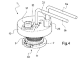
作動装置1自体は、図4から9に詳細に示す。
1 to 3 show an example of the
The
スイッチ装置2は、図1に示す第1の接触位置T2T1に移動自在な電気接触手段3,4,5を備える。この第1の接触位置T2T1において、接触手段3,4,5は2つの端子T2およびTlに接触する。
The
作動装置1による作動後、接触手段3,4,5は、端子T3に向かって移動し、図2に示す中間位置を経る(図10Bの回路図に相当)。この中間位置において、接触手段3,4,5は、ディストリビュータ部材5を介して、端子T1,T2およびT3に接触する(メイクビフォーブレイク(MBB)タイプの切換構成(つまり、コネクションT1T3が閉状態かつコネクションT2T1が開状態になる前の構成)によって、3つの接触端子T1,T2およびT3は共に電気接続されて、これにより、スイッチ装置2が設けられているバッテリの直列接続された回路が開回路となることを避けることができる)。そして、図3に示す第2の接触位置T1T3に到達する。この第2の接触位置T1T3において、接触手段3,4,5は2つの端子T1およびT3に接触する。
After the operation by the
スイッチ装置2の端子T1,T2,T3を適切な手法でマルチセルバッテリのセルの端子に接続することにより、ある決まったセルを、接触手段3,4,5が第1の接触位置T2T1にある際にはこれ以外のセルとの直列接続を維持することを達成し、かつ、接触手段3,4,5が第2の接触位置T1T3にある際には、その決まったセルをこれ以外のセルにもはや直列接続せずにこのセルを迂回することを達成する。
By connecting the terminals T1, T2, and T3 of the
例えば、図10A,10Bおよび10Cに示すように、決まったセルNは、2つのセルN−1およびN+lの間で直列接続されている。そして、スイッチ装置2の端子T1がセルN−lの正端子に接続され、スイッチ装置2の端子T2がセルNの負端子に接続され、スイッチ装置2の端子T3がセルNの正端子に接続されている場合を考察する。
●端子T1と端子T2の間のコネクションが(つまり、第1の接触位置において)達成される(図1および10A)と、セルNはセルN−lとセルN+lの間での直列接続を維持する。
●端子T1と端子T2の間のコネクションがまだ切断されていない状態で端子T1と端子T3の間のコネクションが(つまり、中間接触位置において)設定される(図2および10B)ならば、設定されたT1T3を経由する迂回の可能性を確保しながら、セルNはセルN−lとセルN+lの間で依然として直列接続されている。このため、バッテリの直列接続された回路において開回路は生じない。
●端子T1と端子T2の間の第1の接触位置におけるコネクションがもはや存在しない状態で端子T1と端子T3の間のコネクションが設定されている(図3および10C)と、セルN−1とセルN+1の間におけるセルNの直列接続がなくなる(ただし、セルNの正端子のセルN+lの負端子への接続は維持される)。
For example, as shown in FIGS. 10A, 10B and 10C, a fixed cell N is connected in series between two cells N-1 and N + l. Then, the terminal T1 of the
● When the connection between terminal T1 and terminal T2 is achieved (ie, at the first contact position) (FIGS. 1 and 10A), cell N maintains a series connection between cell N-l and cell N + l. do.
● If the connection between the terminal T1 and the terminal T2 is not yet disconnected and the connection between the terminal T1 and the terminal T3 is set (that is, at the intermediate contact position) (that is, in the intermediate contact position), it is set. Cell N is still connected in series between cell N-l and cell N + l, ensuring the possibility of detour via T1T3. Therefore, no open circuit occurs in the circuit connected in series with the batteries.
● When the connection between the terminal T1 and the terminal T3 is set in a state where the connection at the first contact position between the terminal T1 and the terminal T2 no longer exists (FIGS. 3 and 10C), the cells N-1 and the cell The series connection of cell N between N + 1 is lost (however, the connection of the positive terminal of cell N to the negative terminal of cell N + l is maintained).
なお、スイッチ装置2の別の実施形態を、詳細に図示はしないが、そのバッテリのN−l,N,N+1の直列接続されたセルについての回路図を図11に示す。ここでは、スイッチ装置2の中間位置を、作動後かつ切換え中にブレークビフォーメーク(BBM)の位置で取得することができる。この場合、2つのコネクションT2T1およびT1T3が同時に開放される。
Although another embodiment of the
上記考察は、また、単一のセルNを備えたバッテリの場合にも当てはまる。この場合、セルNは、Tlでバッテリの一方の出力端子に接続され、T3でバッテリの他方の出力端子に接続される。セルNを迂回するための切換えは、上述のように故障の場合にセルNの損傷を避けるためだけでなく、特に、それぞれ少なくとも1つのセルを備えた少なくとも1つの他のバッテリに直列接続される単一のセルバッテリの場合も対象とする。単一のセルバッテリのその唯一のセルが正常に機能しなくなると、切換えによってその不良セルの迂回が可能となり、そのため、上述のように、他のバッテリのセルに影響を及ぼすリスクなしに欠陥バッテリを迂回する。 The above considerations also apply to batteries with a single cell N. In this case, cell N is connected to one output terminal of the battery at Tl and to the other output terminal of the battery at T3. The switch to bypass cell N is not only to avoid damage to cell N in case of failure as described above, but in particular is connected in series to at least one other battery, each with at least one cell. The case of a single cell battery is also covered. If that single cell of a single cell battery fails, the switch allows the bad cell to be bypassed, so, as mentioned above, a defective battery without the risk of affecting the cells of other batteries. Bypass.
スイッチ装置2は、バッテリへのコネクションについての切離し装置に一体化されることができる。この切離し装置は、電流センサ6a,6bの入力線6aに接続されることができる。そのため、決まった大きさの電流が作動装置1の電流センサ6a,6bに運ばれることにより、スイッチ装置2は作動することになる。切離し装置自体は、この切離し装置が接続される1つまたは複数のバッテリセルを迂回することを引き起こすシステムを介して手動または自動で起動されることができる。
The
オプションとして、この切離し装置は、バッテリセルのうちのいずれか1つにおける故障を検出するシステムにさらに接続されてもよい。これにより、バッテリセルのいずれかにおける故障が検出システムによって検出されると、信号が、切離し装置の手動起動のためにオペレータに送信されるか、または、切離し装置の自動作動のために起動システムに送信される。 Optionally, the decoupling device may be further connected to a system that detects a failure in any one of the battery cells. This will cause a signal to be sent to the operator for manual activation of the decoupling device or to the activation system for automatic activation of the decoupling device when a failure in any of the battery cells is detected by the detection system. Will be sent.
このような切離し装置にマルチセルバッテリが装着されると、前記セルの1つが正常に機能しなくなるバッテリの耐用年数を、バッテリへの手動介入を必要とせずに延ばすことができる。オプションとして、不良セルの迂回を自動で引き起こすことに加えて、セルの状態を監視することが自動化されてもよい。 When a multi-cell battery is attached to such a decoupling device, the useful life of a battery in which one of the cells fails can be extended without the need for manual intervention in the battery. Optionally, in addition to automatically triggering the bypass of bad cells, monitoring the state of the cells may be automated.
スイッチ装置2は、絶縁材料からなる本体16を備える。本体16には、接触手段3,4,5および作動装置1が収容される。
The
図1から3の例に示すように、本体16は長手方向軸を有し(長手方向に延び)、その長手方向両端は2つのカバー18および26で閉じられている。本体16に、カバー18は固定手段28,29によって固定され、カバー26は固定手段34,35によって固定されている。図示のように、2つの支持プレート33,40のうちの一方の支持プレート33が固定手段28,29とカバー8の間に介在することができ、他方の支持プレート40が固定手段34,35とカバー26の間に介在することができる。
As shown in the examples of FIGS. 1 to 3, the
接触手段3,4,5は、このため、本体16の内部を長手方向に延び、2つの接触位置T2T1およびT1T3の間を長手方向に移動する。
Therefore, the contact means 3, 4, and 5 extend in the longitudinal direction inside the
接触手段3,4,5はプランジャ3を備える。プランジャ3は、作動装置1の作動前(図1)には、作動装置1に接触係合しているか、または作動装置1の内部にある。プランジャ3は、作動後、作動装置1の長手方向の貫通空間に進入し(図2)、切換えの終端位置と称される終端位置(図3)に至る。
The contact means 3, 4, and 5 include a
図示の例では、プランジャ3には、作動装置1の作動後のプランジャ3の移動範囲における後部近くに、作動後の非常位置を作動装置1への当接から効果的に判定する径方向延在部36が設けられている。
In the illustrated example, the
作動装置1の貫通空間が使用できるようになる(貫通空間が空く)と(すなわち、作動装置1の作動後)プランジャ3を非常位置に自動的に動かすように弾性復元手段17(例えば、ばね17)が配置されている。この目的のために、弾性復元手段17は、ワッシャのような力分配手段41に係止されているが、弾性復元手段17の片側は本体16にプランジャ3のストロークの上流において、当接(押圧)箇所として働く径方向延在部36を介してプランジャ3に連結され、これにより、接触手段3,4,5に連結される。
The elastic restoring means 17 (for example, the spring 17) automatically moves the
したがって、図示の例において、弾性復元手段17は、接触手段3,4,5が第2の接触位置T1T3にあるときは休止位置(非圧縮位置または開放位置)にあり、接触手段3,4,5が第1の接触位T2T1にあるときは活性位置(つまり、弾性手段が圧縮された動作位置)にある。 Therefore, in the illustrated example, the elastic restoring means 17 is in the resting position (uncompressed position or open position) when the contact means 3, 4, 5 are in the second contact position T1T3, and the contact means 3, 4, When 5 is in the first contact position T2T1, it is in the active position (that is, the operating position in which the elastic means is compressed).
そのため、作動装置1が作動すると、弾性復元手段17が動作位置から休止位置に戻ることにより、第1の接触位置T2T1から第2の接触位置T1T3への接触手段3,4,5の自動移行が弾性復元手段17によって確実となる。
Therefore, when the
ディストリビュータ部材5は、接触手段3,4,5の電気接触部材として働くものであるが、非導電体4を介してプランジャ3に接続されている。
The
ディストリビュータ部材5は、スイッチ装置2の接触端子T1,T2,T3のうちの少なくとも2つに接触するのに適している。すなわち、図1および10Aに示すように、第1の接触位置T2T1において、ディストリビュータ部材5は接触端子T1および接触端子T2と接触して、これら2つの端子の間の電気接続を実現する。図3および10Cに示すように、第2の接触位置T1T3において、ディストリビュータ部材5は接触端子T1および接触端子T3と接触して、これら2つの端子の間の電気接続を実現する。
The
なお、図2および10Bを参照して上述したように、ディストリビュータ部材5が作動後かつ切換え中に接触端子T1,T2およびT3と接触できるメイクビフォーブレイク位置にスイッチ装置を配置する中間位置が存在してもよい。これにより、これら端子の間の電気接続を実現するとともに、切換え中におけるバッテリの直列接続回路の開回路を避けることができる。
As described above with reference to FIGS. 2 and 10B, there is an intermediate position for arranging the switch device at the make-before break position where the
図1から3(特に図2)から分かるように、ディストリビュータ部材5のプランジャ側の端部、つまり第1の電気接触位置T2T1から第2の電気接触位置T1T3への接触手段3,4,5の移動方向を向いた端部は、本体16の長手方向に沿って径方向の大きさが減少している。これによって、接触端子T3と接触するディストリビュータ部材5は、その係合が容易になる。
As can be seen from FIGS. 1 to 3 (particularly FIG. 2), the ends of the
好ましくは、導電性で変形可能な材料からなる接触部20,21,22であって、例えば、接触スタッドを保持する帯体のような接触部が、それぞれ、接触端子T3,Tl,T2の内方において、これら接触端子T3,Tl,T2に接触して配置されている。これにより、ディストリビュータ部材5と接触端子T3,Tl,T2の間の電気接触が確実になるとともに、ディストリビュータ部材5が直進し易くなる。
Preferably, the
図示のように、本体16はその一端がカバー18で塞がれている。この一端には、作動装置1が配置されている。作動装置1の作動後に非常位置までプランジャ3を移行できるようにするために、作動装置1内におけるプランジャの移行のための空間に通じる孔19の形態である隙間空間が、カバー18内に設けられている。
As shown in the figure, one end of the
本体16の他端においても、カバー26が本体16を塞いでいる。カバー26に、図2および3に示す空洞37が設けられている。空洞37は、接触手段3,4,5が第1の接触位置T2T1にあるときに、カバー26の方を向くディストリビュータ部材5の端に形成された調芯装置(センタリング装置)27を収容するためのものである。
At the other end of the
調芯装置27とカバー26の空洞37の間の雄雌係合は一実施形態であり、センタリングを達成する同等の他の実施形態であってもよい(例えば、雄雌係合の逆)。
The male-female engagement between the centering
調芯装置27は、可動な接触手段3,4,5の径方向の位置決めだけでなく、部品のアライメントも担う。具体的には、振動(バイブレーション)または衝撃などの機械的応力が存在する場合に、調芯装置27によって径方向の振動(オシレーション)が制限される。特に、径方向接触力を既に受けている接触部20,21,22における応力が緩和される。より詳細には、第1の接触位置における、接触端子T1と接触部21とディストリビュータ部材5の間、接触端子T2と接触部22とディストリビュータ部材5の間、および、オプションとして接触端子T3と接触部20と非導電体4の間、ならびに、第2の接触位置における、接触端子T1と接触部21とディストリビュータ部材5の間、および、接触端子T3と接触部20とディストリビュータ部材5の間が当てはまる。これにより、接触手段3,4,5の負荷抵抗が保証される。
The centering
スイッチ装置2の取付け(特に、弾性復元手段17の活性位置の位置決め)を確実にするために、取付部品と協働するのに適している協働手段を調芯装置27に設けることができる。これにより、取付部品と協働手段が協働すれば、取付部品に作用することで、だれでも接触手段3,4,5を移動させて第2の接触位置T1T3から第1の接触位置T2T1に動かすことができる。調芯装置における協働手段は、例えば、調芯装置27の周囲のねじ山からなってもよく、対応する取付ツールがねじ山に螺合されることができる。この取付ツールは、第1の接触位置から第2の接触位置に向かう接触手段3,4,5の移動方向の上流および下流で径方向の大きさが減少してもよい。これは、ディストリビュータ部材5の径方向の大きさが減少するのとほぼ同様である。そのため、接触端子T1および接触端子T2の下側に接触して、ディストリビュータ部材5の係合および戻りが確実になる。
In order to ensure the mounting of the switch device 2 (particularly, the positioning of the active position of the elastic restoring means 17), the centering
第1の接触位置においてディストリビュータ部材5と接触しない接触端子T3に対応する(すなわち、接触する)接触部20に面する非導電体4のその部分の径を適応したものとするのが有利である。これにより、非導電体4に沿って、かつ接触手段3,4,5の軸心に垂直に、接触端子T3が自動調芯される(調芯され、摺動し、かつ支持するタイプのアセンブリ)。この支持特性が、本体16のある程度の遊びを許容するハウジング内で自重により、接触端子T3のいかなる旋回現象をも防止する。
It is advantageous to adapt the diameter of that portion of the
このため、スイッチ装置2はバッテリに確実に導入されて取り付けられ、アセンブリ(装置全体の)構成に影響を及ぼさない。これにより、装置の電気的機能(電源回路の抵抗)および機械的機能(ディストリビュータ部材の移動)の維持が保証される。
Therefore, the
本発明に係る作動装置1の一例をより詳細に図4から9に示す。ここで、その作動装置1は、図1から3に示すスイッチ装置2に、一体化される前のものである(図4)か、または既に一体化されている(図5から9)。
An example of the
この例において、作動装置1は、電流センサ6a,6bと、線(ワイヤ)タイプの支え部材7によってスプール10と一体に支持された2つの可動部材8,9(つまり2つのジョー(挟持対,2つの顎部材))8,9)とを備える。
In this example, the
電流センサ6a,6bは、スプール10を貫通する電流を供給する線つまりケーブル6aを備える。線つまりケーブル6aは、絶縁部材23によってスプール10から絶縁され、支え部材7に接続されている。ケーブル6aは、バッテリを備え付けるそのスイッチ装置専用のものである。電流センサ6a,6bは、また、例えば、固定手段31でスプール10に固定された導電タブ30によって、スプール10に電気接続された戻り線つまりケーブル6bを備える。ケーブル6bは、同一のバッテリを備え付ける全てのスイッチ装置に共通のものであってもよい。
The
そして、2つの可動部材8,9は、図4,5,7および8に示す第1の構成において、スプール10の周りに巻回された支え部材7によって、スプール10と一体に支持されている。詳細には、可動部材8はスプール10の当接領域14に当接し、可動部材9はスプール10の別の当接領域15に当接する。この第1の構成では、図1から3のスイッチ装置2の接触手段3,4,5のプランジャ3が移動するための空間が十分ではない。そのため、このいわゆる非作動構成では、接触手段3,4,5の変位が抑制される。
Then, in the first configuration shown in FIGS. 4, 5, 7 and 8, the two
第2のいわゆる作動構成において、図6および9に示すように、可動部材8,9はもはや支え部材によって支持されず、可動部材8,9は、それぞれ、回転軸心12,13を介してスプール10に一体のままで軸心12,13を中心として回転する。この回転によって、図1から3のスイッチ装置2の接触手段3,4,5のプランジャ3が進入するのに十分な貫通空間が使用できるようになる。そのため、この作動構成では、接触手段3,4,5の変位が可能となる。
In the second so-called actuating configuration, as shown in FIGS. 6 and 9, the
スプール10の長手方向に貫通する2つのピン12,13によって可動部材8,9のスプール10との一体が確実となり、ピン12,13がそれぞれ可動部材8,9の軸心12,13を構成する。
The two
そのため、ピン12,13に対する可動部材8,9それぞれの回転運動の結果として、作動装置1のスプール10において、スイッチ装置2のプランジャ3のための通路が開かれる。
Therefore, as a result of the rotational movements of the
この貫通空間は、好ましくは、ほぼ円筒形の空間であり、より一般的には、スプール10の中心軸に位置決めされている。2つのピン12,13は、この貫通空間に平行に配置され、通路に対して互いに対称である。このように一旦構成された後は、第1の接触位置T2T1が第2の接触位置T1T3に切り換えられると、可動部材8,9(つまりジョー8,9)におけるピン12,13から最遠の領域が互いに離れる。これにより、スプール10と一体である可動部材(つまりジョー)8,9を依然として支えながら、貫通空間が使用できるようになる。
This penetrating space is preferably a substantially cylindrical space and, more generally, is positioned about the central axis of the
図5および6に示すように,可動部材8,9それぞれに孔24,25が設けられてもよい。これら孔24,25は、たとえ可動部材8,9が既にピン12,13によって支持されていたとしてても、作動装置1の組立中に可動部材8,9がスプール10の当接面14,15に押し当てられることを可能とするのに適している。
As shown in FIGS. 5 and 6, holes 24 and 25 may be provided in the
非作動構成(図5)から作動構成(図6)への切換えは、電流供給線6a(または代わりに、同様に電流を供給することができる線6b)によって供給される、一定強度の電流であって、可動部材(つまりジョー)8,9の周りに巻回されたワイヤタイプの支え部材7の両端のうちの一端39に接続されている電流センサからの電流によって、達成される。支え部材7の他端は、図5においてより明確に分かるように、スプール10に接続されている。
Switching from the non-working configuration (FIG. 5) to the working configuration (FIG. 6) is carried out by a constant intensity current supplied by the
図7および8によってより明確に分かるように、支え部材7は、接続部材32を通って、電流センサ6a,6bの電流供給線6aにヒューズ線11を介して接続されている。この接続部材32は絶縁部材23内に収容されている。そして、前記絶縁部材23は、スプール10の内部に収容されている。一定強度の電流が電流センサ6a,6bの電流供給線6a(または代わりに線6b)によって供給されるとヒューズ線11が溶融し、これにより、支え部材7をその端39で解放する。支え部材7はほどかれ、それに伴い可動部材(つまりジョー)8,9が解放される。このため、可動部材(つまりジョー)8,9は、弾性復元手段17の付勢によるプランジャ3の押圧によって、図6の作動構成にピン12,13を中心として回転することができる。
As can be more clearly seen in FIGS. 7 and 8, the
ヒューズ線11は、好ましくは、ループ11の形態をとる。この場合、支え部材7の解放のためのトリガ電流つまり作動電流を電流センサ6a,6bが運んでこない限りは良好な機械的強度を保証するとともに、ヒューズ線が切断する位置の良好な制御が得られる。そのため、ヒューズ線11をループ形状にすることによって、簡易で意図したとおりの実現が可能となり、かつ、電気的・機械的強度と、支え部材7のその端39での効果的な解放との良好な妥協点がもたらされる。
The
絶縁部材23と、絶縁部材23内部の接続部材32を介する電流センサ6a,6bの電流供給線6a、およびスプール10の取付構造とが、電流供給線6a、接続部材32、絶縁部材23、スプール10およびヒューズ線11を備えたアセンブリのいかなる動きも許容しない。特に、絶縁部材23の形状は、絶縁部材23の回転を抑制するように、スプール10のカウンタボア(座ぐり)に嵌合する形状である。さらに、接続部材32の接着および圧着により、接続部材32が絶縁部材23内で回転するのを防止することができる。そのため、支え部材7を支えるヒューズ線11のループが損傷するのが防止される。
The insulating
さらに、カバー18における電流センサ6a,6bの線の通路と、ほぼ90°でL字状に曲がった経路とのための貫通孔によって、これら線6a,6bが回転しないという妥当な保証がもたらされる。
In addition, the through holes for the line passages of the
そのため、ヒューズ線11のループの端39を介して支え部材7を引っ張ると、線6a、接続部材32および絶縁部材23を備えたアセンブリはスプール10に押し当てられる傾向にある。
Therefore, when the
さらに、電流センサ6a,6bの線6aのための通路を受け入れてこの通路として機能する、カバー18におけるカウンタボアによって、線6a、接続部材32および絶縁部材23を備えるアセンブリの軸方向位置の妥当な保証がもたらされる。
In addition, the counterbore in the
支え部材7に関しては、スプール10に、支え部材7の他端38で機械的に支えられている。このようにして、作動装置1の電気経路(直列と並列の両方)は、電流供給線6aおよびヒューズ線11(線6aとヒューズ線11を接続する接続部材32)と、支え部材7と、スプール10と、可動部材(つまりジョー)8,9と、ピン12,13と、導電タブ30と、戻り線6bとを備える。このような作動装置1は「自立した」と称される。
The
さらに、ヒューズ線のループ11が2つの可動部材8,9に極めて近いため、支え部材7のコネクションとヒューズ線のループ11の間の距離が短い。これにより、支え部材7がヒューズ線のループ11によって解放されると、支え部材7がほどかれる間に本体16において支え部材7の端39(つまり枝状の部材)からの妨害のリスクが抑えられる。
Further, since the
そのため、全ての金属部分は、アクセス可能な浮遊電位に接続可能である。これら電位は、より詳細には、以下の通りである。
●作動前後における、環状の力分配手段41、弾性復元手段17、プランジャ3、可動部材8,9、ピン12,13、スプール10、支え部材7、電流センサ6b,6a、接続部材32、導電タブ30(および、ねじ31)ならびにヒューズ線11のための電流センサの線6a,6bの電位、
●切換前後における、接触部20,21,22、接触端子T1,T2,T3、ならびにディストリビュータ部材5のための接触端子T1,T2およびT3とのインタフェースでの電源回路の電位、
●例えば、固定手段28,29および34,35ならびにアセンブリの機械的結合として機能する支持プレート33,40の接地電位。
Therefore, all metal parts can be connected to an accessible floating potential. More specifically, these potentials are as follows.
● Circular force distribution means 41, elastic restoration means 17,
● The potential of the power supply circuit at the interface with the
● For example, the ground potentials of the fixing means 28, 29 and 34, 35 and the
本開示は、例示のためのものであり、本発明を限定するものではない。特に、作動装置1およびスイッチ装置2の形状および様々な部品について、例示に過ぎない。具体的には、可動部材8,9が、スプール10との一体が解除されることなく非作動構成から作動構成に移動できる限りにおいて、可動部材8,9の形状は図示のものに限定されるわけではない。
なお、本発明は、態様として以下の内容を含む。
〔態様1〕
第1の電気接触位置(T2T1)および第2の電気接触位置(T1T3)の間で移動可能な電気的な接触手段(3,4,5)を有するタイプのスイッチ装置(2)における切換えを行う作動装置(1)であって、
電流センサ(6a,6b)と、
支え部材(7)と、
スプール(10)と一体である少なくとも2つの可動部材(8,9)であって、前記電流センサ(6a,6b)によって一定の電流が検出されると、非作動構成から作動構成に切り換えられるように構成された少なくとも2つの可動部材(8,9)とを備え、
前記非作動構成では、前記スイッチ装置(2)の前記接触手段(3,4,5)の移動を抑制する第1の位置に前記2つの可動部材(8,9)が前記支え部材(7)によって支持されおり、
前記作動構成では、前記2つの可動部材(8,9)がもはや前記第1の位置に前記支え部材(7)によって支持されず、前記2つの可動部材(8,9)は前記スイッチ装置(2)の前記接触手段(3,4,5)が位置を変更することを許容する第2の位置にある、作動装置(1)において、
前記スプール(10)には前記スイッチ装置(2)の前記接触手段(3,4,5)の少なくとも一部(3)のための貫通空間が設けられており、
前記2つの可動部材(8,9)が、前記第2の位置では、前記スプール(10)と一体のまま、前記貫通空間が使用できるようにそれぞれ軸心(12,13)を中心として回転可動であることを特徴とする作動装置(1)。
〔態様2〕
態様1に記載の作動装置(1)において、前記スプール(10)は前記2つの可動部材(8,9)それぞれに対する当接領域(14,15)を有し、前記第1の位置において、前記2つの可動部材(8,9)は、前記当接領域(14,15)のうちのそれぞれ対応する当接領域(14,15)への当接が前記支え部材(7)によって維持されている、作動装置(1)。
〔態様3〕
態様1または2に記載の作動装置(1)において、前記2つの可動部材(8,9)の前記2つの軸心(12,13)が、前記スプール(10)と一体であるピン(12,13)によって構成されていることを特徴とする作動装置(1)。
〔態様4〕
態様3に記載の作動装置(1)において、
前記貫通空間は、前記スプール(10)の中心軸に位置決めされた貫通空間(好ましくは、ほぼ円筒形)であり、
前記2つのピン(12,13)は、前記貫通空間に平行に配置され、かつ、前記貫通空間に対して互いに対称であり、
前記2つの可動部材(8,9)は2つのジョー部材(8,9)の形態を有し、これにより、前記第1の位置から前記第2の位置への切換えの間、前記2つのジョー部材(8,9)それぞれの領域であって、前記ピン(12,13)のうちの対応するピンから最遠の領域が前記貫通空間へのアクセスを自由にするために互いに遠ざかることを特徴とする作動装置(1)。
〔態様5〕
態様1から4のいずれか一態様に記載の作動装置(1)において、
前記電流センサ(6a,6b)が電流供給線(6a)を備え、
前記支え部材(7)がワイヤタイプであり、前記第1の位置において、当該支え部材(7)の両端(38,39)のうちの一端(38)が前記スプール(10)に接続され、当該支え部材(7)は前記2つの可動部材(8,9)の周りに巻回され、当該支え部材(7)の両端(38,39)のうちの他端(39)が前記電流センサ(6a,6b)の前記電流供給線(6a)にヒューズ線(11)によって接続されており、これにより、前記電流センサ(6a,6b)によって一定の電流が検出されると、前記ヒューズ線(11)が溶融して前記支え部材(7)の前記他端(39)を解放することで、前記2つの可動部材(8,9)が前記第2の位置に移行できるようにすることを特徴とする作動装置(1)。
〔態様6〕
態様5に記載の作動装置(1)において、前記ヒューズ線(11)がループ構成である、作動装置(1)。
〔態様7〕
態様5または6に記載の作動装置(1)において、
前記ヒューズ線(11)が(好ましくは接続部材(32)によって)前記電流センサ(6a,6b)の前記電流供給線(6a)に前記スプール(10)を通って接続されており、
絶縁部材(23)が、前記ヒューズ線(11)(オプションとして、前記接続部材(32))および前記電流センサ(6a,6b)の前記電流供給線(6a)を含む集合体と前記スプール(10)の間に介在することを特徴とする作動装置(1)。
〔態様8〕
本体(16)を備えたスイッチ装置(2)であって、
この本体(16)に、接触手段(3,4,5)が第1の電気接触位置(T2T1)と第2の電気接触位置(T1T3))の間で移動自在に収容されている、スイッチ装置(2)において、
当該スイッチ装置(2)が、態様1から態様7のいずれか一態様に記載の作動装置(1)であって、前記本体(16)に内蔵された作動装置を備えることにより、当該作動装置(1)が前記作動構成にあるとき、前記第1の電気接触位置(T2T1)から前記第2の電気接触位置(T1T3)に前記接触手段(3,4,5)が変位できることを特徴とするスイッチ装置(2)。
〔態様9〕
態様8に記載のスイッチ装置(2)において、
前記本体(16)は長手方向軸を有し、当該本体(16)の長手方向に前記接触手段(3,4,5)が延びており、
前記接触手段(3,4,5)の少なくとも一部のための前記貫通空間が長手方向に延びるように、前記作動装置(1)が前記本体(16)内に配置されていることを特徴とするスイッチ装置(2)。
〔態様10〕
態様9に記載のスイッチ装置(2)において、前記接触手段(3,4,5)が、前記接触手段(3,4,5)を前記第1の電気接触位置(T2T1)から前記第2の電気接触位置(T1T3)に変位させるように前記貫通空間において長手方向に移動自在であるプランジャ(3)を備えたスイッチ装置(2)。
〔態様11〕
態様10に記載のスイッチ装置(2)において、
弾性復元手段(17)(例えば、ばね(17))であって、一方の側では前記本体(16)に(好ましくは、力分配手段(41)(例えば、環状の力分配手段(41))によって)接続され、他方の側では前記接触手段(3,4,5)に接続された弾性復元手段(17)を備え、前記接触手段(3,4,5)が前記第2の電気接触位置(T1T3)にあるときに前記弾性復元手段(17)は弛緩位置に配設されており、前記接触手段(3,4,5)が前記第1の電気接触位置(T2T1)にあるときに前記弾性復元手段(17)は活性位置に配設されており、そのため、前記弾性復元手段(17)が前記活性位置から前記弛緩位置に戻ることで、前記接触手段(3,4,5)が前記第1の電気接触位置(T2T1)から前記第2の電気接触位置(T1T3)に自動移行できることを特徴とするスイッチ装置(2)。
〔態様12〕
態様10または11に記載のスイッチ装置(2)において、
前記接触手段(3,4,5)は、前記プランジャ(3)に非導電体(4)によって接続されたディストリビュータ部材(5)を有し,前記ディストリビュータ部材(5)は、前記第1の電気接触位置(T2T1)において電気的な第1の接触端子(T2)および電気的な第2の接触端子(Tl)と接触し、前記第2の電気接触位置(T1T3)において前記第2の接触端子(Tl)および電気的な第3の接触端子(T3)と接触することを特徴とするスイッチ装置(2)。
〔態様13〕
態様12に記載のスイッチ装置(2)において、前記第1の電気接触位置(T2T1)から前記第2の電気接触位置(T1T3)への前記接触手段(3,4,5)の移動方向を向いた前記ディストリビュータ部材(5)の端部は、前記本体(16)の長手方向に沿って径方向の大きさが減少しており、これにより、前記第3の接触端子(T3)と接触する前記ディストリビュータ部材(5)の前記第3の接触端子(T3)との係合が促進される、スイッチ装置(2)。
〔態様14〕
態様12または13に記載のスイッチ装置(2)において、
導電性で変形可能な材料からなる接触部(20,21,22)であって、前記接触端子(T3,Tl,T2)の対応する接触端子に接触して配置され、かつ、前記第1の電気接触位置(T2T1)から前記第2の電気接触位置(T1T3)への前記ディストリビュータ部材(5)の移動に応じて前記ディストリビュータ部材(5)に接触し、これにより、前記ディストリビュータ部材(5)と前記接触端子(Tl,T2,T3)の少なくとも1つとの間の電気接触が損なわれないようにする、接触部(20,21,22)を備えたことを特徴とするスイッチ装置(2)。
〔態様15〕
態様14に記載のスイッチ装置(2)において、第1の電気接触位置において前記ディストリビュータ部材(5)と接触しない前記接触端子(T3)と接触する前記接触部材(20)に面する前記非導電体(4)のその部分の径は、前記接触端子(T3)が、前記非導電体(4)に沿って、かつ前記接触手段(3,4,5)の軸心に垂直に、自動調芯姿勢をとるのに適合しており、これにより、調芯され、摺動し、かつ支持するタイプのアセンブリが得られる、スイッチ装置(2)。
〔態様16〕
態様8から15のいずれか一態様に記載のスイッチ装置(2)において、
前記作動装置(1)は前記本体(16)の一端に配置され、前記一端が第1のカバー(18)で塞がれていることを特徴とするスイッチ装置(2)。
〔態様17〕
態様16に記載のスイッチ装置(2)において、
前記第1のカバー(18)に、前記作動装置(1)の前記スプール(10)における貫通空間に通じる隙間空間(19)が設けられており、これにより、前記スイッチ装置(2)の前記接触手段(3,4,5)の前記少なくとも一部(3)が、前記作動装置(1)を通って前記隙間空間(19)に入り込むことができることを特徴とするスイッチ装置(2)。
〔態様18〕
態様16または17に記載のスイッチ装置(2)において、
前記本体(16)は、前記第1のカバー(18)で塞がれている前記一端とは反対側の他端において、空洞が設けられた第2のカバー(26)で塞がれており、
前記ディストリビュータ部材(5)には、前記第2のカバー(26)に面する一端に、前記第2のカバー(26)の前記空洞に収容される調芯装置(27)が設けられていることを特徴とするスイッチ装置(2)。
〔態様19〕
態様18に記載のスイッチ装置(2)において、
前記調芯装置(27)に、協働手段(例えば、ねじ山)であって、前記接触部(20,21,21,22)を損傷せずに前記接触端子(T3,Tl,T2)が前記ディストリビュータ部材(5)に組み付けられることができ、かつ、前記接触手段(3,4,5)が前記第2の電気接触位置(T1T3)から前記第1の電気接触位置(T2T1)に移動することができるようにするための取付部品と協働することを可能にするのに適合した協働手段が設けられていることを特徴とするスイッチ装置(2)。
〔態様20〕
態様8から19のいずれか一態様に記載のスイッチ装置(2)において、
前記第1の電気接触位置において、前記第2の電気接触位置において、かつ、前記第1の電気接触位置から前記第2の電気接触位置への切換え中において、前記装置の全ての金属部分が一つの電位に接続されていることを特徴とするスイッチ装置(2)。
〔態様21〕
直列に接続された複数のセルを含むバッテリの少なくとも1つの決まったセルを切り離す切離し装置であって、
前記バッテリに接続されるのに適合した切離し装置において、
態様8から20のいずれか一態様に記載のスイッチ装置(2)を備え、
前記作動装置(1)の前記電流センサ(6a,6b)に接続され、これにより、前記スイッチ装置(2)は、前記第1の電気接触位置(T2T1)であって、前記決まったセルが他のセルと直列に接続されている第1の電気接触位置(T2T1)から、前記第2の電気接触位置(T1T3)であって、前記決まったセルが迂回されて他のセルとはもはや直列に接続されない第2の電気接触位置(T1T3)に移行できることを特徴とする切離し装置。
〔態様22〕
直列に接続されている少なくとも1つのセルを備えたバッテリにおいて、
態様21に記載の切離し装置が設けられていることを特徴とするバッテリ。
The present disclosure is for illustration purposes only and is not intended to limit the present invention. In particular, the shapes and various parts of the
The present invention includes the following contents as aspects.
[Aspect 1]
Switching is performed in a switch device (2) of a type having electrical contact means (3, 4, 5) that can be moved between a first electrical contact position (T2T1) and a second electrical contact position (T1T3). The operating device (1)
Current sensors (6a, 6b) and
Support member (7) and
At least two movable members (8, 9) integrated with the spool (10), so that when a constant current is detected by the current sensor (6a, 6b), the non-operating configuration is switched to the operating configuration. With at least two movable members (8, 9) configured in
In the non-operating configuration, the two movable members (8, 9) are placed at the first position of suppressing the movement of the contact means (3, 4, 5) of the switch device (2). Supported by
In the actuating configuration, the two movable members (8, 9) are no longer supported in the first position by the support member (7), and the two movable members (8, 9) are the switch device (2). ) In the actuating device (1), which is in a second position that allows the contact means (3, 4, 5) to change position.
The spool (10) is provided with a through space for at least a part (3) of the contact means (3, 4, 5) of the switch device (2).
At the second position, the two movable members (8, 9) can rotate around the axis (12, 13) so that the through space can be used while being integrated with the spool (10). (1).
[Aspect 2]
In the actuating device (1) according to
[Aspect 3]
In the actuating device (1) according to
[Aspect 4]
In the actuating device (1) according to
The penetrating space is a penetrating space (preferably substantially cylindrical) positioned on the central axis of the spool (10).
The two pins (12, 13) are arranged parallel to the penetrating space and symmetrical with respect to the penetrating space.
The two movable members (8, 9) have the form of two jaw members (8, 9), whereby the two jaws are used during the switching from the first position to the second position. Each region of the member (8, 9), the region farthest from the corresponding pin of the pins (12, 13), is characterized in that the regions are separated from each other in order to freely access the penetrating space. Actuating device (1).
[Aspect 5]
In the actuating device (1) according to any one of
The current sensor (6a, 6b) includes a current supply line (6a).
The support member (7) is a wire type, and at the first position, one end (38) of both ends (38, 39) of the support member (7) is connected to the spool (10). The support member (7) is wound around the two movable members (8, 9), and the other end (39) of both ends (38, 39) of the support member (7) is the current sensor (6a). , 6b) is connected to the current supply line (6a) by a fuse wire (11), and when a constant current is detected by the current sensor (6a, 6b), the fuse wire (11) Is melted to release the other end (39) of the support member (7) so that the two movable members (8, 9) can move to the second position. Actuating device (1).
[Aspect 6]
In the actuating device (1) according to the fifth aspect, the actuating device (1) in which the fuse wire (11) has a loop configuration.
[Aspect 7]
In the actuating device (1) according to
The fuse wire (11) is connected (preferably by a connecting member (32)) to the current supply wire (6a) of the current sensor (6a, 6b) through the spool (10).
The insulating member (23) includes an assembly including the fuse wire (11) (optionally, the connecting member (32)) and the current supply wire (6a) of the current sensors (6a, 6b) and the spool (10). ), The actuating device (1).
[Aspect 8]
A switch device (2) equipped with a main body (16).
A switch device in which contact means (3, 4, 5) are movably housed in the main body (16) between a first electrical contact position (T2T1) and a second electrical contact position (T1T3). In (2)
The switch device (2) is the actuating device (1) according to any one of
[Aspect 9]
In the switch device (2) according to the eighth aspect,
The main body (16) has a longitudinal axis, and the contact means (3, 4, 5) extends in the longitudinal direction of the main body (16).
The actuating device (1) is arranged in the main body (16) so that the penetrating space for at least a part of the contact means (3, 4, 5) extends in the longitudinal direction. Switch device (2).
[Aspect 10]
In the switch device (2) according to the ninth aspect, the contact means (3,4,5) moves the contact means (3,4,5) from the first electrical contact position (T2T1) to the second. A switch device (2) provided with a plunger (3) that is movable in the longitudinal direction in the through space so as to be displaced to an electrical contact position (T1T3).
[Aspect 11]
In the switch device (2) according to the tenth aspect,
Elastic restoring means (17) (eg, spring (17)) on one side to the body (16) (preferably force distributing means (41) (eg, annular force distributing means (41))). On the other side, there is an elastic restoring means (17) connected to the contact means (3,4,5), and the contact means (3,4,5) is in the second electrical contact position. The elastic restoring means (17) is arranged at a relaxed position when at (T1T3), and the contact means (3, 4, 5) is at the first electrical contact position (T2T1). The elastic restoring means (17) is arranged at the active position. Therefore, when the elastic restoring means (17) returns from the active position to the relaxed position, the contact means (3, 4, 5) is said to be the same. The switch device (2) is characterized in that it can automatically shift from the first electric contact position (T2T1) to the second electric contact position (T1T3).
[Aspect 12]
In the switch device (2) according to the
The contact means (3, 4, 5) has a distributor member (5) connected to the plunger (3) by a non-conductor (4), and the distributor member (5) has the first electricity. At the contact position (T2T1), it comes into contact with the electrical first contact terminal (T2) and the electrical second contact terminal (Tl), and at the second electrical contact position (T1T3), the second contact terminal. A switch device (2) characterized in contact with (Tl) and an electrical third contact terminal (T3).
[Aspect 13]
In the switch device (2) according to the twelfth aspect, the moving direction of the contact means (3, 4, 5) from the first electric contact position (T2T1) to the second electric contact position (T1T3) is directed. The end portion of the distributor member (5) that has been there is reduced in radial size along the longitudinal direction of the main body (16), whereby the end portion that comes into contact with the third contact terminal (T3) is said to be in contact with the third contact terminal (T3). A switch device (2) in which engagement of the distributor member (5) with the third contact terminal (T3) is promoted.
[Aspect 14]
In the switch device (2) according to
A contact portion (20,21,22) made of a conductive and deformable material, which is arranged in contact with the corresponding contact terminal of the contact terminal (T3, Tl, T2) and is arranged in contact with the first contact terminal. The distributor member (5) comes into contact with the distributor member (5) in response to the movement of the distributor member (5) from the electrical contact position (T2T1) to the second electrical contact position (T1T3), whereby the distributor member (5) and the distributor member (5) are contacted. The switch device (2) is provided with contact portions (20, 21, 22) so that electrical contact with at least one of the contact terminals (Tl, T2, T3) is not impaired.
[Aspect 15]
In the switch device (2) according to
[Aspect 16]
In the switch device (2) according to any one of
The switch device (2) is characterized in that the operating device (1) is arranged at one end of the main body (16), and the one end is closed by a first cover (18).
[Aspect 17]
In the switch device (2) according to
The first cover (18) is provided with a gap space (19) leading to a through space in the spool (10) of the operating device (1), whereby the contact of the switch device (2). The switch device (2), characterized in that at least a part (3) of the means (3, 4, 5) can enter the gap space (19) through the operating device (1).
[Aspect 18]
In the switch device (2) according to
The main body (16) is closed by a second cover (26) provided with a cavity at the other end opposite to the one end closed by the first cover (18). ,
The distributor member (5) is provided with a centering device (27) housed in the cavity of the second cover (26) at one end facing the second cover (26). The switch device (2).
[Aspect 19]
In the switch device (2) according to
The centering device (27) is provided with the contact terminals (T3, Tl, T2), which are collaborative means (for example, threads) and do not damage the contact portions (20, 21, 21, 22, 22). It can be assembled to the distributor member (5), and the contact means (3, 4, 5) moves from the second electrical contact position (T1T3) to the first electrical contact position (T2T1). A switch device (2) characterized in that it is provided with suitable collaborative means to allow it to collaborate with mounting components to enable it.
[Aspect 20]
In the switch device (2) according to any one of
At the first electrical contact position, at the second electrical contact position, and during switching from the first electrical contact position to the second electrical contact position, all metal parts of the apparatus are one. A switch device (2) characterized by being connected to one potential.
[Aspect 21]
A decoupling device that detaches at least one fixed cell of a battery containing multiple cells connected in series.
In a decoupling device suitable for being connected to the battery
The switch device (2) according to any one of
It is connected to the current sensors (6a, 6b) of the actuating device (1), whereby the switch device (2) is at the first electrical contact position (T2T1), and the determined cell is the other. From the first electrical contact position (T2T1) connected in series with the cell to the second electrical contact position (T1T3), the determined cell is bypassed and is no longer in series with the other cells. A decoupling device characterized in that it can shift to a second electrical contact position (T1T3) that is not connected.
[Aspect 22]
In a battery with at least one cell connected in series
A battery comprising the decoupling device according to
Claims (22)
電流センサ(6a,6b)と、
支え部材(7)と、
スプール(10)と一体である少なくとも2つの可動部材(8,9)であって、前記電流センサ(6a,6b)によって一定の電流が検出されると、非作動構成から作動構成に切り換えられるように構成された少なくとも2つの可動部材(8,9)とを備え、
前記非作動構成では、前記スイッチ装置(2)の前記接触手段(3,4,5)の移動を抑制する第1の位置に前記2つの可動部材(8,9)が前記支え部材(7)によって支持されおり、
前記作動構成では、前記2つの可動部材(8,9)がもはや前記第1の位置に前記支え部材(7)によって支持されず、前記2つの可動部材(8,9)は前記スイッチ装置(2)の前記接触手段(3,4,5)が位置を変更することを許容する第2の位置にある、作動装置(1)において、
前記スプール(10)には前記スイッチ装置(2)の前記接触手段(3,4,5)の少なくとも一部(3)のための貫通空間が設けられており、
前記2つの可動部材(8,9)が、前記第2の位置では、前記スプール(10)と一体のまま、前記貫通空間が使用できるようにそれぞれ軸心(12,13)を中心として回転可動であることを特徴とする作動装置(1)。 Switching is performed in a switch device (2) of a type having electrical contact means (3, 4, 5) that can be moved between a first electrical contact position (T2T1) and a second electrical contact position (T1T3). The operating device (1)
Current sensors (6a, 6b) and
Support member (7) and
At least two movable members (8, 9) integrated with the spool (10), so that when a constant current is detected by the current sensor (6a, 6b), the non-operating configuration is switched to the operating configuration. With at least two movable members (8, 9) configured in
In the non-operating configuration, the two movable members (8, 9) are placed at the first position of suppressing the movement of the contact means (3, 4, 5) of the switch device (2). Supported by
In the actuating configuration, the two movable members (8, 9) are no longer supported in the first position by the support member (7), and the two movable members (8, 9) are the switch device (2). ) In the actuating device (1), which is in a second position that allows the contact means (3, 4, 5) to change position.
The spool (10) is provided with a through space for at least a part (3) of the contact means (3, 4, 5) of the switch device (2).
At the second position, the two movable members (8, 9) can rotate around the axis (12, 13) so that the through space can be used while being integrated with the spool (10). (1).
前記貫通空間は、前記スプール(10)の中心軸に位置決めされた貫通空間であり、
前記2つのピン(12,13)は、前記貫通空間に平行に配置され、かつ、前記貫通空間に対して互いに対称であり、
前記2つの可動部材(8,9)は2つのジョー部材(8,9)の形態を有し、これにより、前記第1の位置から前記第2の位置への切換えの間、前記2つのジョー部材(8,9)それぞれの領域であって、前記ピン(12,13)のうちの対応するピンから最遠の領域が前記貫通空間へのアクセスを自由にするために互いに遠ざかることを特徴とする作動装置(1)。 In the operating device (1) according to claim 3.
The penetrating space is a penetrating space positioned on the central axis of the spool (10).
The two pins (12, 13) are arranged parallel to the penetrating space and symmetrical with respect to the penetrating space.
The two movable members (8, 9) have the form of two jaw members (8, 9), whereby the two jaws are used during the switching from the first position to the second position. Each region of the member (8, 9), the region farthest from the corresponding pin of the pins (12, 13), is characterized in that the regions are separated from each other in order to freely access the penetrating space. Actuating device (1).
前記電流センサ(6a,6b)が電流供給線(6a)を備え、
前記支え部材(7)がワイヤタイプであり、前記第1の位置において、当該支え部材(7)の両端(38,39)のうちの一端(38)が前記スプール(10)に接続され、当該支え部材(7)は前記2つの可動部材(8,9)の周りに巻回され、当該支え部材(7)の両端(38,39)のうちの他端(39)が前記電流センサ(6a,6b)の前記電流供給線(6a)にヒューズ線(11)によって接続されており、これにより、前記電流センサ(6a,6b)によって一定の電流が検出されると、前記ヒューズ線(11)が溶融して前記支え部材(7)の前記他端(39)を解放することで、前記2つの可動部材(8,9)が前記第2の位置に移行できるようにすることを特徴とする作動装置(1)。 In the operating device (1) according to any one of claims 1 to 4.
The current sensor (6a, 6b) includes a current supply line (6a).
The support member (7) is a wire type, and at the first position, one end (38) of both ends (38, 39) of the support member (7) is connected to the spool (10). The support member (7) is wound around the two movable members (8, 9), and the other end (39) of both ends (38, 39) of the support member (7) is the current sensor (6a). , 6b) is connected to the current supply line (6a) by a fuse wire (11), and when a constant current is detected by the current sensor (6a, 6b), the fuse wire (11) Is melted to release the other end (39) of the support member (7) so that the two movable members (8, 9) can move to the second position. Actuating device (1).
前記ヒューズ線(11)が前記電流センサ(6a,6b)の前記電流供給線(6a)に前記スプール(10)を通って接続されており、
絶縁部材(23)が、前記ヒューズ線(11)および前記電流センサ(6a,6b)の前記電流供給線(6a)を含む集合体と前記スプール(10)の間に介在することを特徴とする作動装置(1)。 In the actuating device (1) according to claim 5 or 6.
The fuse wire (11) is connected to the current supply wire (6a) of the current sensor (6a, 6b) through the spool (10).
The insulating member (23) is interposed between the spool (10) and the assembly including the fuse wire (11) and the current supply wire (6a) of the current sensors (6a, 6b). Actuating device (1).
この本体(16)に、接触手段(3,4,5)が第1の電気接触位置(T2T1)と第2の電気接触位置(T1T3)の間で移動自在に収容されている、スイッチ装置(2)において、
当該スイッチ装置(2)が、請求項1から請求項7のいずれか一項に記載の作動装置(1)であって、前記本体(16)に内蔵された作動装置を備えることにより、当該作動装置(1)が前記作動構成にあるとき、前記第1の電気接触位置(T2T1)から前記第2の電気接触位置(T1T3)に前記接触手段(3,4,5)が変位できることを特徴とするスイッチ装置(2)。 A switch device (2) equipped with a main body (16).
A switch device (16) in which contact means (3, 4, 5) are movably housed between a first electrical contact position (T2T1) and a second electrical contact position (T1T3). In 2)
The switch device (2) is the actuating device (1) according to any one of claims 1 to 7, wherein the switch device (2) is provided with an actuating device built in the main body (16). When the device (1) is in the operating configuration, the contact means (3, 4, 5) can be displaced from the first electrical contact position (T2T1) to the second electrical contact position (T1T3). Switch device (2).
前記本体(16)は長手方向軸を有し、当該本体(16)の長手方向に前記接触手段(3,4,5)が延びており、
前記接触手段(3,4,5)の少なくとも一部のための前記貫通空間が長手方向に延びるように、前記作動装置(1)が前記本体(16)内に配置されていることを特徴とするスイッチ装置(2)。 In the switch device (2) according to claim 8,
The main body (16) has a longitudinal axis, and the contact means (3, 4, 5) extends in the longitudinal direction of the main body (16).
The actuating device (1) is arranged in the main body (16) so that the penetrating space for at least a part of the contact means (3, 4, 5) extends in the longitudinal direction. Switch device (2).
弾性復元手段(17)であって、一方の側では前記本体(16)に接続され、他方の側では前記接触手段(3,4,5)に接続された弾性復元手段(17)を備え、前記接触手段(3,4,5)が前記第2の電気接触位置(T1T3)にあるときに前記弾性復元手段(17)は弛緩位置に配設されており、前記接触手段(3,4,5)が前記第1の電気接触位置(T2T1)にあるときに前記弾性復元手段(17)は活性位置に配設されており、そのため、前記弾性復元手段(17)が前記活性位置から前記弛緩位置に戻ることで、前記接触手段(3,4,5)が前記第1の電気接触位置(T2T1)から前記第2の電気接触位置(T1T3)に自動移行できることを特徴とするスイッチ装置(2)。 In the switch device (2) according to claim 10,
An elastic return means (17), is on one side is connected to said body (16), provided with elastic return means connected to said contact means (3,4,5) (17) on the other side When the contact means (3, 4, 5) is in the second electrical contact position (T1T3), the elastic restoring means (17) is arranged in a relaxed position, and the contact means (3, 4) , 5) is at the first electrical contact position (T2T1), the elastic restoring means (17) is arranged at the active position, so that the elastic restoring means (17) is said from the active position. By returning to the relaxed position, the switch device (3, 4, 5) can automatically shift from the first electric contact position (T2T1) to the second electric contact position (T1T3). 2).
前記接触手段(3,4,5)は、前記プランジャ(3)に非導電体(4)によって接続されたディストリビュータ部材(5)を有し,前記ディストリビュータ部材(5)は、前記第1の電気接触位置(T2T1)において電気的な第1の接触端子(T2)および電気的な第2の接触端子(Tl)と接触し、前記第2の電気接触位置(T1T3)において前記第2の接触端子(Tl)および電気的な第3の接触端子(T3)と接触することを特徴とするスイッチ装置(2)。 In the switch device (2) according to claim 10 or 11.
The contact means (3, 4, 5) has a distributor member (5) connected to the plunger (3) by a non-conductor (4), and the distributor member (5) has the first electricity. At the contact position (T2T1), it comes into contact with the electrical first contact terminal (T2) and the electrical second contact terminal (Tl), and at the second electrical contact position (T1T3), the second contact terminal. A switch device (2) characterized in contact with (Tl) and an electrical third contact terminal (T3).
導電性で変形可能な材料からなる接触部(20,21,22)であって、前記接触端子(T3,Tl,T2)の対応する接触端子に接触して配置され、かつ、前記第1の電気接触位置(T2T1)から前記第2の電気接触位置(T1T3)への前記ディストリビュータ部材(5)の移動に応じて前記ディストリビュータ部材(5)に接触し、これにより、前記ディストリビュータ部材(5)と前記接触端子(Tl,T2,T3)の少なくとも1つとの間の電気接触が損なわれないようにする、接触部(20,21,22)を備えたことを特徴とするスイッチ装置(2)。 In the switch device (2) according to claim 12 or 13.
A contact portion (20,21,22) made of a conductive and deformable material, which is arranged in contact with the corresponding contact terminal of the contact terminal (T3, Tl, T2) and is arranged in contact with the first contact terminal. The distributor member (5) comes into contact with the distributor member (5) in response to the movement of the distributor member (5) from the electrical contact position (T2T1) to the second electrical contact position (T1T3), whereby the distributor member (5) and the distributor member (5) are contacted. The switch device (2) is provided with contact portions (20, 21, 22) so that electrical contact with at least one of the contact terminals (Tl, T2, T3) is not impaired.
前記作動装置(1)は前記本体(16)の一端に配置され、前記一端が第1のカバー(18)で塞がれていることを特徴とするスイッチ装置(2)。 In the switch device (2) according to any one of claims 8 to 15.
The switch device (2) is characterized in that the operating device (1) is arranged at one end of the main body (16), and the one end is closed by a first cover (18).
前記第1のカバー(18)に、前記作動装置(1)の前記スプール(10)における貫通空間に通じる隙間空間(19)が設けられており、これにより、前記スイッチ装置(2)の前記接触手段(3,4,5)の前記少なくとも一部(3)が、前記作動装置(1)を通って前記隙間空間(19)に入り込むことができることを特徴とするスイッチ装置(2)。 In the switch device (2) according to claim 16,
The first cover (18) is provided with a gap space (19) leading to a through space in the spool (10) of the operating device (1), whereby the contact of the switch device (2). The switch device (2), characterized in that at least a part (3) of the means (3, 4, 5) can enter the gap space (19) through the operating device (1).
前記本体(16)は、前記第1のカバー(18)で塞がれている前記一端とは反対側の他端において、空洞が設けられた第2のカバー(26)で塞がれており、
前記ディストリビュータ部材(5)には、前記第2のカバー(26)に面する一端に、前記第2のカバー(26)の前記空洞に収容される調芯装置(27)が設けられていることを特徴とするスイッチ装置(2)。 In the switch device (2) according to claim 16 or 17, when any one of claims 12 to 15 is cited.
The main body (16) is closed by a second cover (26) provided with a cavity at the other end opposite to the one end closed by the first cover (18). ,
The distributor member (5) is provided with a centering device (27) housed in the cavity of the second cover (26) at one end facing the second cover (26). The switch device (2).
前記調芯装置(27)に、協働手段であって、前記接触部(20,21,21,22)を損傷せずに前記接触端子(T3,Tl,T2)が前記ディストリビュータ部材(5)に組み付けられることができ、かつ、前記接触手段(3,4,5)が前記第2の電気接触位置(T1T3)から前記第1の電気接触位置(T2T1)に移動することができるようにするための取付部品と協働することを可能にするのに適合した協働手段が設けられていることを特徴とするスイッチ装置(2)。 In the switch device (2) according to claim 18, when claim 14 is cited.
The contact terminals (T3, Tl, T2) are provided to the centering device (27) as a collaborative means without damaging the contact portions (20, 21, 12, 22) to the distributor member (5). And allows the contact means (3, 4, 5) to move from the second electrical contact position (T1T3) to the first electrical contact position (T2T1). A switch device (2), characterized in that it is provided with a collaborative means adapted to allow it to collaborate with a mounting component for the purpose.
前記第1の電気接触位置において、前記第2の電気接触位置において、かつ、前記第1の電気接触位置から前記第2の電気接触位置への切換え中において、前記装置の全ての金属部分が一つの電位に接続されていることを特徴とするスイッチ装置(2)。 In the switch device (2) according to any one of claims 8 to 19.
At the first electrical contact position, at the second electrical contact position, and during switching from the first electrical contact position to the second electrical contact position, all metal parts of the apparatus are one. A switch device (2) characterized by being connected to one potential.
前記バッテリに接続されるのに適合した切離し装置において、
請求項8から20のいずれか一項に記載のスイッチ装置(2)を備え、
前記作動装置(1)の前記電流センサ(6a,6b)に接続され、これにより、前記スイッチ装置(2)は、前記第1の電気接触位置(T2T1)であって、前記決まったセルが他のセルと直列に接続されている第1の電気接触位置(T2T1)から、前記第2の電気接触位置(T1T3)であって、前記決まったセルが迂回されて他のセルとはもはや直列に接続されない第2の電気接触位置(T1T3)に移行できることを特徴とする切離し装置。 A decoupling device that detaches at least one fixed cell of a battery containing multiple cells connected in series.
In a decoupling device suitable for being connected to the battery
The switch device (2) according to any one of claims 8 to 20 is provided.
It is connected to the current sensors (6a, 6b) of the actuating device (1), whereby the switch device (2) is at the first electrical contact position (T2T1), and the determined cell is the other. From the first electrical contact position (T2T1) connected in series with the cell to the second electrical contact position (T1T3), the determined cell is bypassed and is no longer in series with the other cells. A decoupling device characterized in that it can shift to a second electrical contact position (T1T3) that is not connected.
請求項21に記載の切離し装置が設けられていることを特徴とするバッテリ。 In a battery with at least one cell connected in series
A battery according to claim 21, wherein the disconnection device is provided.
Applications Claiming Priority (3)
| Application Number | Priority Date | Filing Date | Title |
|---|---|---|---|
| FR1663257A FR3061353B1 (en) | 2016-12-22 | 2016-12-22 | SELF-ACTIVATION DEVICE FOR ELECTROMECHANICAL SWITCH |
| FR1663257 | 2016-12-22 | ||
| PCT/FR2017/050288 WO2018115604A2 (en) | 2016-12-22 | 2017-02-08 | Self-supported activation device for an electromechanical switch |
Publications (2)
| Publication Number | Publication Date |
|---|---|
| JP2020514967A JP2020514967A (en) | 2020-05-21 |
| JP6964138B2 true JP6964138B2 (en) | 2021-11-10 |
Family
ID=58707664
Family Applications (1)
| Application Number | Title | Priority Date | Filing Date |
|---|---|---|---|
| JP2019534327A Active JP6964138B2 (en) | 2016-12-22 | 2017-02-08 | Self-supporting actuator for electromechanical switches |
Country Status (6)
| Country | Link |
|---|---|
| US (1) | US11270860B2 (en) |
| EP (1) | EP3559973B1 (en) |
| JP (1) | JP6964138B2 (en) |
| CN (1) | CN110178198B (en) |
| FR (1) | FR3061353B1 (en) |
| WO (1) | WO2018115604A2 (en) |
Family Cites Families (13)
| Publication number | Priority date | Publication date | Assignee | Title |
|---|---|---|---|---|
| JP2536786Y2 (en) * | 1991-07-03 | 1997-05-28 | 関東自動車工業株式会社 | Press-type side pin retaining device |
| US5362576A (en) * | 1992-07-31 | 1994-11-08 | Reynolds Industries, Incorporated | Current-activated bypass switch |
| DE19649739C2 (en) * | 1996-11-30 | 1998-11-12 | Daimler Benz Aerospace Ag | Release device for hold-down z. B. on solar generators |
| US6249063B1 (en) * | 1998-03-17 | 2001-06-19 | Nea Electronics, Inc. | Battery cell bypass with frangible actuator |
| JP2001263221A (en) * | 2000-03-22 | 2001-09-26 | Minolta Co Ltd | Control device using actuator including shape memory alloy |
| JP4339167B2 (en) * | 2004-04-07 | 2009-10-07 | 本田技研工業株式会社 | Fastening device |
| FR2902232B1 (en) * | 2006-06-07 | 2008-07-18 | Souriau Soc Par Actions Simpli | SWITCH FOR DEVICE FOR DERIVING AN ELECTRICAL COMPONENT |
| US8568053B2 (en) * | 2008-04-14 | 2013-10-29 | Space Systems/Loral, Llc | Radial release device |
| FR2938710B1 (en) * | 2008-11-14 | 2010-11-12 | Saft Groupe Sa | ELECTRIC BYPASS DEVICE |
| JP2012095438A (en) * | 2010-10-26 | 2012-05-17 | Seiko Instruments Inc | Charge/discharge control circuit and battery device |
| US8987935B2 (en) * | 2011-12-30 | 2015-03-24 | Allen King | Uninterruptible battery power for electric motor vehicle |
| EP2662139A1 (en) * | 2012-05-08 | 2013-11-13 | Roche Diagniostics GmbH | A valve for dispensing a fluid |
| US9456863B2 (en) * | 2013-03-11 | 2016-10-04 | Covidien Lp | Surgical instrument with switch activation control |
-
2016
- 2016-12-22 FR FR1663257A patent/FR3061353B1/en active Active
-
2017
- 2017-02-08 CN CN201780080351.XA patent/CN110178198B/en active Active
- 2017-02-08 WO PCT/FR2017/050288 patent/WO2018115604A2/en unknown
- 2017-02-08 US US16/471,157 patent/US11270860B2/en active Active
- 2017-02-08 JP JP2019534327A patent/JP6964138B2/en active Active
- 2017-02-08 EP EP17882281.3A patent/EP3559973B1/en active Active
Also Published As
| Publication number | Publication date |
|---|---|
| CN110178198B (en) | 2021-12-28 |
| EP3559973B1 (en) | 2023-08-30 |
| JP2020514967A (en) | 2020-05-21 |
| WO2018115604A2 (en) | 2018-06-28 |
| CN110178198A (en) | 2019-08-27 |
| EP3559973A2 (en) | 2019-10-30 |
| US20200006029A1 (en) | 2020-01-02 |
| US11270860B2 (en) | 2022-03-08 |
| WO2018115604A3 (en) | 2018-10-25 |
| FR3061353A1 (en) | 2018-06-29 |
| FR3061353B1 (en) | 2019-05-10 |
Similar Documents
| Publication | Publication Date | Title |
|---|---|---|
| TW552608B (en) | Electrical circuit interrupting device | |
| KR101213480B1 (en) | Battery protecting circuit and controlling method of the same | |
| JP6209011B2 (en) | Battery overcharge prevention device | |
| JP2012515998A (en) | Protection device for galvanicel | |
| KR102044598B1 (en) | Apparatus and method for detect malfunction of battery pack | |
| JP6829485B2 (en) | Health monitoring and safety protection and applications for lithium-ion battery modules | |
| JP2993933B1 (en) | Conductive contact pin with thermal fuse function | |
| CN106796859A (en) | Switching device for an overvoltage protection device | |
| JP6964138B2 (en) | Self-supporting actuator for electromechanical switches | |
| CN1983492A (en) | Protective circuit switch with time-delay trigger | |
| KR102530250B1 (en) | System for supplying electrical energy to the submarine's on-board network | |
| KR20170031062A (en) | Battery system with an overcharge protection and/or deep discharge protection | |
| EP3706153B1 (en) | Low-voltage power distribution device capable of detecting predetermined state | |
| CN103380555A (en) | Protective device | |
| US8247929B2 (en) | Electrical bypass device | |
| CN105259516A (en) | A back-up type UPS input switch abnormity detection apparatus | |
| US20130154392A1 (en) | System for bypassing and isolating electrical power cells | |
| CN210778468U (en) | Circuit breaker testing device and circuit breaker with same | |
| JP5834919B2 (en) | Power storage device and vehicle | |
| KR102074308B1 (en) | Circuit-closing device | |
| JP3217998B2 (en) | Conductive contact pin with thermal fuse function | |
| US11509159B2 (en) | System and method for thermal cutoff protection device control from an external component | |
| CN203398052U (en) | Multifunctional breaker | |
| CN217061960U (en) | Earth leakage circuit breaker | |
| US10312045B2 (en) | Interruption apparatus employing actuator having movable engagement element |
Legal Events
| Date | Code | Title | Description |
|---|---|---|---|
| A521 | Request for written amendment filed |
Free format text: JAPANESE INTERMEDIATE CODE: A523 Effective date: 20200128 |
|
| A621 | Written request for application examination |
Free format text: JAPANESE INTERMEDIATE CODE: A621 Effective date: 20200128 |
|
| A977 | Report on retrieval |
Free format text: JAPANESE INTERMEDIATE CODE: A971007 Effective date: 20210226 |
|
| A131 | Notification of reasons for refusal |
Free format text: JAPANESE INTERMEDIATE CODE: A131 Effective date: 20210309 |
|
| A601 | Written request for extension of time |
Free format text: JAPANESE INTERMEDIATE CODE: A601 Effective date: 20210603 |
|
| A521 | Request for written amendment filed |
Free format text: JAPANESE INTERMEDIATE CODE: A523 Effective date: 20210902 |
|
| TRDD | Decision of grant or rejection written | ||
| A01 | Written decision to grant a patent or to grant a registration (utility model) |
Free format text: JAPANESE INTERMEDIATE CODE: A01 Effective date: 20211005 |
|
| A61 | First payment of annual fees (during grant procedure) |
Free format text: JAPANESE INTERMEDIATE CODE: A61 Effective date: 20211018 |
|
| R150 | Certificate of patent or registration of utility model |
Ref document number: 6964138 Country of ref document: JP Free format text: JAPANESE INTERMEDIATE CODE: R150 |