JP6963607B2 - Systems and methods for syringe micropumps with wave springs - Google Patents
Systems and methods for syringe micropumps with wave springs Download PDFInfo
- Publication number
- JP6963607B2 JP6963607B2 JP2019520137A JP2019520137A JP6963607B2 JP 6963607 B2 JP6963607 B2 JP 6963607B2 JP 2019520137 A JP2019520137 A JP 2019520137A JP 2019520137 A JP2019520137 A JP 2019520137A JP 6963607 B2 JP6963607 B2 JP 6963607B2
- Authority
- JP
- Japan
- Prior art keywords
- syringe
- wave spring
- pump housing
- plunger
- removable
- Prior art date
- Legal status (The legal status is an assumption and is not a legal conclusion. Google has not performed a legal analysis and makes no representation as to the accuracy of the status listed.)
- Active
Links
Images


Classifications
-
- A—HUMAN NECESSITIES
- A61—MEDICAL OR VETERINARY SCIENCE; HYGIENE
- A61M—DEVICES FOR INTRODUCING MEDIA INTO, OR ONTO, THE BODY; DEVICES FOR TRANSDUCING BODY MEDIA OR FOR TAKING MEDIA FROM THE BODY; DEVICES FOR PRODUCING OR ENDING SLEEP OR STUPOR
- A61M5/00—Devices for bringing media into the body in a subcutaneous, intra-vascular or intramuscular way; Accessories therefor, e.g. filling or cleaning devices, arm-rests
- A61M5/14—Infusion devices, e.g. infusing by gravity; Blood infusion; Accessories therefor
- A61M5/142—Pressure infusion, e.g. using pumps
- A61M5/145—Pressure infusion, e.g. using pumps using pressurised reservoirs, e.g. pressurised by means of pistons
- A61M5/1452—Pressure infusion, e.g. using pumps using pressurised reservoirs, e.g. pressurised by means of pistons pressurised by means of pistons
- A61M5/1454—Pressure infusion, e.g. using pumps using pressurised reservoirs, e.g. pressurised by means of pistons pressurised by means of pistons spring-actuated, e.g. by a clockwork
-
- A—HUMAN NECESSITIES
- A61—MEDICAL OR VETERINARY SCIENCE; HYGIENE
- A61M—DEVICES FOR INTRODUCING MEDIA INTO, OR ONTO, THE BODY; DEVICES FOR TRANSDUCING BODY MEDIA OR FOR TAKING MEDIA FROM THE BODY; DEVICES FOR PRODUCING OR ENDING SLEEP OR STUPOR
- A61M5/00—Devices for bringing media into the body in a subcutaneous, intra-vascular or intramuscular way; Accessories therefor, e.g. filling or cleaning devices, arm-rests
- A61M5/14—Infusion devices, e.g. infusing by gravity; Blood infusion; Accessories therefor
- A61M5/142—Pressure infusion, e.g. using pumps
- A61M5/145—Pressure infusion, e.g. using pumps using pressurised reservoirs, e.g. pressurised by means of pistons
- A61M5/1452—Pressure infusion, e.g. using pumps using pressurised reservoirs, e.g. pressurised by means of pistons pressurised by means of pistons
- A61M5/1456—Pressure infusion, e.g. using pumps using pressurised reservoirs, e.g. pressurised by means of pistons pressurised by means of pistons with a replaceable reservoir comprising a piston rod to be moved into the reservoir, e.g. the piston rod is part of the removable reservoir
-
- A—HUMAN NECESSITIES
- A61—MEDICAL OR VETERINARY SCIENCE; HYGIENE
- A61M—DEVICES FOR INTRODUCING MEDIA INTO, OR ONTO, THE BODY; DEVICES FOR TRANSDUCING BODY MEDIA OR FOR TAKING MEDIA FROM THE BODY; DEVICES FOR PRODUCING OR ENDING SLEEP OR STUPOR
- A61M5/00—Devices for bringing media into the body in a subcutaneous, intra-vascular or intramuscular way; Accessories therefor, e.g. filling or cleaning devices, arm-rests
- A61M5/14—Infusion devices, e.g. infusing by gravity; Blood infusion; Accessories therefor
- A61M5/142—Pressure infusion, e.g. using pumps
- A61M5/145—Pressure infusion, e.g. using pumps using pressurised reservoirs, e.g. pressurised by means of pistons
- A61M5/1452—Pressure infusion, e.g. using pumps using pressurised reservoirs, e.g. pressurised by means of pistons pressurised by means of pistons
- A61M5/1458—Means for capture of the plunger flange
-
- A—HUMAN NECESSITIES
- A61—MEDICAL OR VETERINARY SCIENCE; HYGIENE
- A61M—DEVICES FOR INTRODUCING MEDIA INTO, OR ONTO, THE BODY; DEVICES FOR TRANSDUCING BODY MEDIA OR FOR TAKING MEDIA FROM THE BODY; DEVICES FOR PRODUCING OR ENDING SLEEP OR STUPOR
- A61M5/00—Devices for bringing media into the body in a subcutaneous, intra-vascular or intramuscular way; Accessories therefor, e.g. filling or cleaning devices, arm-rests
- A61M5/14—Infusion devices, e.g. infusing by gravity; Blood infusion; Accessories therefor
- A61M5/168—Means for controlling media flow to the body or for metering media to the body, e.g. drip meters, counters ; Monitoring media flow to the body
-
- A—HUMAN NECESSITIES
- A61—MEDICAL OR VETERINARY SCIENCE; HYGIENE
- A61M—DEVICES FOR INTRODUCING MEDIA INTO, OR ONTO, THE BODY; DEVICES FOR TRANSDUCING BODY MEDIA OR FOR TAKING MEDIA FROM THE BODY; DEVICES FOR PRODUCING OR ENDING SLEEP OR STUPOR
- A61M5/00—Devices for bringing media into the body in a subcutaneous, intra-vascular or intramuscular way; Accessories therefor, e.g. filling or cleaning devices, arm-rests
- A61M5/14—Infusion devices, e.g. infusing by gravity; Blood infusion; Accessories therefor
- A61M5/142—Pressure infusion, e.g. using pumps
- A61M5/145—Pressure infusion, e.g. using pumps using pressurised reservoirs, e.g. pressurised by means of pistons
- A61M5/1452—Pressure infusion, e.g. using pumps using pressurised reservoirs, e.g. pressurised by means of pistons pressurised by means of pistons
- A61M2005/14573—Pressure infusion, e.g. using pumps using pressurised reservoirs, e.g. pressurised by means of pistons pressurised by means of pistons with a replaceable reservoir for quick connection/disconnection with a driving system
-
- A—HUMAN NECESSITIES
- A61—MEDICAL OR VETERINARY SCIENCE; HYGIENE
- A61M—DEVICES FOR INTRODUCING MEDIA INTO, OR ONTO, THE BODY; DEVICES FOR TRANSDUCING BODY MEDIA OR FOR TAKING MEDIA FROM THE BODY; DEVICES FOR PRODUCING OR ENDING SLEEP OR STUPOR
- A61M5/00—Devices for bringing media into the body in a subcutaneous, intra-vascular or intramuscular way; Accessories therefor, e.g. filling or cleaning devices, arm-rests
- A61M5/14—Infusion devices, e.g. infusing by gravity; Blood infusion; Accessories therefor
- A61M5/142—Pressure infusion, e.g. using pumps
- A61M5/145—Pressure infusion, e.g. using pumps using pressurised reservoirs, e.g. pressurised by means of pistons
- A61M5/1452—Pressure infusion, e.g. using pumps using pressurised reservoirs, e.g. pressurised by means of pistons pressurised by means of pistons
- A61M5/14546—Front-loading type injectors
-
- A—HUMAN NECESSITIES
- A61—MEDICAL OR VETERINARY SCIENCE; HYGIENE
- A61M—DEVICES FOR INTRODUCING MEDIA INTO, OR ONTO, THE BODY; DEVICES FOR TRANSDUCING BODY MEDIA OR FOR TAKING MEDIA FROM THE BODY; DEVICES FOR PRODUCING OR ENDING SLEEP OR STUPOR
- A61M5/00—Devices for bringing media into the body in a subcutaneous, intra-vascular or intramuscular way; Accessories therefor, e.g. filling or cleaning devices, arm-rests
- A61M5/14—Infusion devices, e.g. infusing by gravity; Blood infusion; Accessories therefor
- A61M5/162—Needle sets, i.e. connections by puncture between reservoir and tube ; Connections between reservoir and tube
-
- A—HUMAN NECESSITIES
- A61—MEDICAL OR VETERINARY SCIENCE; HYGIENE
- A61M—DEVICES FOR INTRODUCING MEDIA INTO, OR ONTO, THE BODY; DEVICES FOR TRANSDUCING BODY MEDIA OR FOR TAKING MEDIA FROM THE BODY; DEVICES FOR PRODUCING OR ENDING SLEEP OR STUPOR
- A61M5/00—Devices for bringing media into the body in a subcutaneous, intra-vascular or intramuscular way; Accessories therefor, e.g. filling or cleaning devices, arm-rests
- A61M5/178—Syringes
- A61M5/31—Details
- A61M5/3129—Syringe barrels
- A61M5/3137—Specially designed finger grip means, e.g. for easy manipulation of the syringe rod
-
- F—MECHANICAL ENGINEERING; LIGHTING; HEATING; WEAPONS; BLASTING
- F16—ENGINEERING ELEMENTS AND UNITS; GENERAL MEASURES FOR PRODUCING AND MAINTAINING EFFECTIVE FUNCTIONING OF MACHINES OR INSTALLATIONS; THERMAL INSULATION IN GENERAL
- F16F—SPRINGS; SHOCK-ABSORBERS; MEANS FOR DAMPING VIBRATION
- F16F1/00—Springs
- F16F1/02—Springs made of steel or other material having low internal friction; Wound, torsion, leaf, cup, ring or the like springs, the material of the spring not being relevant
- F16F1/04—Wound springs
- F16F1/046—Wound springs with partial nesting of inner and outer coils
Description
(関連出願の相互参照)
本出願は、2016年10月12日に出願された「ウェーブスプリングを備えるシリンジマイクロポンプのためのシステムおよび方法(SYSTEM AND METHOD FOR A SYRINGE MICRO PUMP WITH WAVE SPRING)」という名称の米国特許仮出願第62/407,376号について、米国特許法第119条(e)に規定の利益を主張し、この米国特許仮出願の開示は、参照によって本明細書に組み込まれる。
(Cross-reference of related applications)
This application is a U.S. patent provisional application entitled "Systems and Methods for Sinter Micropumps with Wave Spring (SYSTEM AND METHOD FOR A SYRINGE MICRO PUMP WITH WAVE SPRING)" filed on October 12, 2016. For 62 / 407,376, claiming the benefits provided for in Section 119 (e) of the US Patent Act, the disclosure of this US patent provisional application is incorporated herein by reference.
(技術分野)
本発明は、一般に、満たされたシリンジから患者への注入ラインを介した薬剤の供給に使用することができるシリンジポンプに関する。ポンプは、シリンジの胴部内のプランジャシールに力を加えて、溶液をシリンジから注入ラインに移動させるように作用する。ポンプによってプランジャシールに加えられる力を予め設定することによって、溶液の注入の継続時間を管理することができる。ポンプはコンパクトなので、向きを考慮する必要がなく、引っ掛かって注入を遅延させる伝統的なシリンジプランジャのように、外側に動く部品のリスクもないポンプの動作を可能にする。
(Technical field)
The present invention generally relates to a syringe pump that can be used to supply a drug from a filled syringe through an infusion line to a patient. The pump acts to force the plunger seal in the body of the syringe to move the solution from the syringe to the infusion line. The duration of solution injection can be controlled by presetting the force applied to the plunger seal by the pump. The compact size of the pump allows the pump to operate without the risk of outward-moving parts, like traditional syringe plungers, which do not need to be oriented and delay injection by catching.
シリンジポンプは、シリンジから注入ラインを通って患者に溶液を注入するために一般的に使用されている。注入は、一般に、或る時間期間にわたってゆっくりと生じる。 Syringe pumps are commonly used to inject a solution from a syringe through an infusion line into a patient. The infusion generally occurs slowly over a period of time.
典型的なシリンジは、いくつかの周知の言うまでもない構成要素で構成され、そのうちのいくつかは、ノズルと1組のフィンガグリップとの間の胴部、胴部内に配置されたプランジャシール、およびプランジャであり、プランジャは、操作者が第1の場合において例えばノズルによってシリンジの胴部に溶液を引き込むためにプランジャシールをノズルから遠ざかる方向に引っ張ることができ、第2の場合においてノズルによって胴部から溶液を送出するためにプランジャシールをノズルに向かって押し込む/駆動することができるように、プランジャシールに取り付けられ、フィンガグリップよりも突出する。 A typical syringe is composed of several well-known components, some of which are the fuselage between the nozzle and a pair of finger grips, the plunger seal located within the fuselage, and the plunger. The plunger can pull the plunger seal away from the nozzle in the first case, for example, to draw the solution into the body of the syringe by the nozzle, and in the second case, from the body by the nozzle. Attached to the plunger seal and protruding beyond the finger grip so that the plunger seal can be pushed / driven towards the nozzle to deliver the solution.
したがって、プランジャが実質的にシリンジの胴部とほぼ同じ長さであることは、充分に理解および予想される。さらに、溶液が充てんされたとき、シリンジの全長、すなわち胴部とプランジャとを合わせた長さは、胴部単独の長さの約2倍になり得る。 Therefore, it is well understood and expected that the plunger will be substantially as long as the body of the syringe. Furthermore, when the solution is filled, the overall length of the syringe, i.e. the combined length of the torso and plunger, can be about twice the length of the torso alone.
したがって、機械式のシリンジポンプは、伝統的に、プランジャを収容し、初期の伸長した状態から完全に押し込まれた入れ子状の状態までの前進を機械的に生じさせることができるように、伸長したプランジャと少なくとも同じ長さである。 Therefore, mechanical syringe pumps have traditionally been extended so that they can accommodate the plunger and mechanically generate an advance from the initial extended state to a fully indented nested state. At least the same length as the plunger.
したがって、機械式のシリンジポンプは、少なくとも2つの問題を本質的にもたらし、この問題は、この問題がなければシリンジポンプの使用が望まれ得るいくつかの状況で望ましくない。第1の問題は、シリンジポンプが、プランジャの動作範囲に適応することによって、全体としてのシリンジの長さを著しく増加させることである。全体としてのシリンジの長さは一般に、少なくとも、完全に引き出されたときのシリンジの長さおよびプランジャの長さである。 Therefore, mechanical syringe pumps inherently pose at least two problems, which are undesirable in some situations where the use of syringe pumps may be desirable without this problem. The first problem is that the syringe pump significantly increases the overall length of the syringe by adapting to the operating range of the plunger. The length of the syringe as a whole is generally at least the length of the syringe and the length of the plunger when fully retracted.
この長さの増加は、その長さが、使用中のシリンジおよびポンプの持ち運びを望ましくないものおよび/または困難なものとし得る点で、少なくとも第2の要因を付加する。さらに、ハウジングの長さが、プランジャの作動に適応するための長さであるため、シリンジポンプの振動がプランジャに害を及ぼし、結果としてシリンジポンプの機能を妨げる可能性がある。 This increase in length adds at least a second factor in that the length can make carrying the syringe and pump in use undesirable and / or difficult. In addition, because the length of the housing is long enough to adapt to the operation of the plunger, the vibration of the syringe pump can harm the plunger and, as a result, interfere with the functioning of the syringe pump.
さらに、典型的なシリンジポンプは、使用中にコートのポケットまたはズボンのポケットに邪魔にならずに配置することが不可能である。 Moreover, typical syringe pumps cannot be placed unobtrusively in coat pockets or trouser pockets during use.
さらに、多くシリンジポンプは、配電網に接続すること、または電池のいずれかによって電気的に動力が与えられる。第1の場合、配電網に頼ると、患者が配電網への接続の領域から離れることを望んだとしても、シリンジポンプを使用中に容易に持ち運ぶことができない。第2の場合、電池を収容することで、シリンジポンプに余分な空間および重量が必要になり、やはり持ち運びの容易さが損なわれる可能性がある。 In addition, many syringe pumps are electrically powered either by connecting to the grid or by batteries. In the first case, relying on the grid does not allow the syringe pump to be easily carried during use, even if the patient wishes to leave the area of connection to the grid. In the second case, accommodating the battery requires extra space and weight in the syringe pump, which can also impair portability.
したがって、上記で特定された課題のうちの1つ以上を克服することができるシリンジポンプのための方法およびシステムが、必要とされている。 Therefore, there is a need for methods and systems for syringe pumps that can overcome one or more of the challenges identified above.
本発明は、ウェーブスプリングを備える着脱式シリンジマイクロポンプのための新規なシステムおよび方法を提供することによって、先行技術の問題を解決する。 The present invention solves the problems of the prior art by providing novel systems and methods for removable syringe micropumps with wave springs.
具体的には、あくまでも例として、本発明の一実施形態によれば、ウェーブスプリングを備える着脱式シリンジマイクロポンプのためのシステムであって、第1の端部、該第1の端部の反対側の取り付け端部、および両者の間の少なくとも1つの側壁を有するとともに、前記第1の端部に近接したベースを有するポンプハウジングであって、前記取り付け端部は、シリンジに一時的に係合するような構造および配置の取り付け具を有するポンプハウジングと、前記ハウジングの内部に収められ、前記ベースに近接して取り付けられた少なくとも1つのウェーブスプリングとを含み、前記ウェーブスプリングは、該ウェーブスプリングが張力下で圧縮され、該ウェーブスプリングの初期高さがポンプハウジング内に配置される、圧縮された第1の位置と、張力の解放によって該ウェーブスプリングが通常は前記ポンプハウジングから遠ざかる方向に伸びる第2の伸長した位置とを有し、前記ウェーブスプリングは、係合した前記シリンジの胴部内を通過するように予め選択された直径を有し、前記ウェーブスプリングは、係合した前記シリンジのプランジャシールと係合するような構造および配置の遠位端をさらに有し、前記第1の位置と前記第2の位置との間の張力の解放は、前記ウェーブスプリングの前記遠位端が前記プランジャシールを前記シリンジのノズルに向かって移動させることを可能にする、着脱式シリンジマイクロポンプのためのシステムが提供される。 Specifically, as an example, according to one embodiment of the present invention, a system for a removable syringe micropump provided with a wave spring, the first end, the opposite of the first end. A pump housing having a side mounting end and at least one side wall between the two and a base close to the first end, wherein the mounting end temporarily engages the syringe. The wave spring comprises a pump housing having a fitting of such a structure and arrangement and at least one wave spring housed inside the housing and mounted in close proximity to the base. A first compressed position where the wave spring is compressed under tension and the initial height of the wave spring is located within the pump housing, and the release of tension causes the wave spring to extend in a direction that normally moves away from the pump housing. It has two extended positions, the wave spring has a diameter preselected to pass through the body of the engaged syringe, and the wave spring is a plunger seal of the engaged syringe. The distal end of the structure and arrangement that engages with is further provided, and the release of tension between the first position and the second position is such that the distal end of the wave spring is the plunger seal. A system for a removable syringe micropump is provided that allows the to be moved towards the nozzle of the syringe.
別の実施形態においては、ウェーブスプリングを備える着脱式シリンジマイクロポンプのためのシステムであって、ベースが設けられている第1の端部、および該第1の端部の反対側の取り付け端部を有する円筒形のポンプハウジングであって、前記取り付け端部は、該円筒形のポンプを一時的に取り付けることができるシリンジによって提供される1組のフィンガグリップに一時的に結合するような構造および配置の少なくとも1つのフランジを提供し、該円筒形のポンプは、中心の長手軸を有する円筒形のポンプハウジングと、前記ベースに近接して前記長手軸を中心にして前記ポンプハウジング内に配置された少なくとも1つのウェーブスプリングとを含み、前記ウェーブスプリングは、第1の張力下の位置をもたらすように該ウェーブスプリングの遠位端が圧縮されるときに前記円筒形のポンプの内側に収まるように軸方向に圧縮可能であり、前記ウェーブスプリングの高さは、前記第1の張力下の位置まで圧縮された時、前記円筒形のポンプハウジングの長さとほぼ同じであり、前記ウェーブスプリングは、シリンジの胴部の内側で摺動するために充分な直径を有するようにさらに選択され、前記ウェーブスプリングの前記遠位端は、係合した前記シリンジのプランジャシールと係合するような構造および配置である、着脱式シリンジマイクロポンプのためのシステムが提供される。 In another embodiment, a system for a removable syringe micropump with a wave spring, the first end on which the base is provided, and the mounting end opposite to the first end. A cylindrical pump housing having a structure such that the mounting end is temporarily coupled to a set of finger grips provided by a syringe to which the cylindrical pump can be temporarily mounted. Provided at least one flange of the arrangement, the cylindrical pump is disposed in the pump housing with a central longitudinal axis and in the vicinity of the base and centered on the longitudinal axis. Including at least one wave spring so that the wave spring fits inside the cylindrical pump when the distal end of the wave spring is compressed to provide a position under first tension. It is axially compressible and the height of the wave spring is approximately the same as the length of the cylindrical pump housing when compressed to the position under the first tension, the wave spring is a syringe. Further selected to have sufficient diameter to slide inside the body of the wave spring, the distal end of the wave spring is constructed and arranged to engage the plunger seal of the engaged syringe. A system for a removable syringe micropump is provided.
さらに別の実施形態においては、ウェーブスプリングを備える着脱式シリンジマイクロポンプを使用して、シリンジから溶液を送出する方法であって、ノズルと1組のフィンガグリップとの間に延びる胴部、および前記胴部内に前記フィンガグリップに近接して配置されたプランジャシールを有し、前記プランジャシールと前記ノズルとの間に溶液が配置されているシリンジを用意するステップと、円筒形のポンプハウジング、渦巻きばね、および渦巻きばね拘束具を含む着脱式シリンジマイクロポンプを用意するステップであって、前記円筒形のポンプハウジングは、ベースを備える第1の端部、および該第1の端部の反対側の取り付け端部を有し、前記取り付け端部は、前記シリンジの前記フィンガグリップに一時的に結合するような構造および配置の少なくとも1つのフランジを提供し、前記円筒形のポンプは、中心の長手軸を有しており、前記ウェーブスプリングは、前記ベースに近接して前記長手軸を中心にして前記円筒形のポンプハウジング内に配置され、前記ウェーブスプリングは、張力のかかった第1の位置をもたらすように該ウェーブスプリングの遠位端が圧縮されるときに前記円筒形のポンプの内側に収まるように圧縮可能であり、前記ウェーブスプリングの高さは、前記円筒形のポンプハウジングの長さとほぼ同じであり、前記ウェーブスプリングは、前記シリンジの前記胴部の内側で摺動するために充分な直径を有するようにさらに選択され、前記ウェーブスプリングの前記遠位端は、前記係合したシリンジのプランジャシールと係合するような構造および配置であり、前記ウェーブスプリング拘束具は、操作者によって解除されるまで前記ウェーブスプリングを前記初期の張力位置に保持するような構造および配置である、着脱式シリンジマイクロポンプを用意するステップと、前記着脱式ばね付勢マイクロポンプを前記シリンジに取り付けるステップと、前記ウェーブスプリングの前記遠位端が前記シリンジの前記プランジャシールと係合することを可能にするために前記ウェーブスプリング拘束具を解除するステップであって、前記第1の位置からの張力の解放によって、前記ウェーブスプリングの前記遠位端で前記プランジャシールを前記シリンジの前記ノズルに向かって移動させることにより、前記シリンジからの溶液の送出が可能になる、前記ウェーブスプリング拘束具を解除するステップとを含む方法が提供される。 In yet another embodiment, a removable syringe micropump with a wave spring is used to deliver the solution from the syringe, a body extending between the nozzle and a pair of finger grips, and said. A step of preparing a syringe having a plunger seal arranged in the body close to the finger grip and a solution arranged between the plunger seal and the nozzle, a cylindrical pump housing, and a spiral spring. , And a step of preparing a removable syringe micropump that includes a spiral spring restraint, wherein the cylindrical pump housing is attached to a first end with a base and the opposite side of the first end. The mounting end has an end, the mounting end provides at least one flange of construction and arrangement such that it temporarily couples to the finger grip of the syringe, the cylindrical pump has a central longitudinal axis. The wave spring is located in the cylindrical pump housing close to the base and centered on the longitudinal axis so that the wave spring provides a tensioned first position. When the distal end of the wave spring is compressed, it can be compressed so that it fits inside the cylindrical pump, and the height of the wave spring is approximately the same as the length of the cylindrical pump housing. Yes, the wave spring is further selected to have a diameter sufficient to slide inside the body of the syringe, and the distal end of the wave spring is the plunger seal of the engaged syringe. The removable syringe micro has a structure and arrangement such that it engages with, and the wave spring restraint has a structure and arrangement that holds the wave spring in the initial tension position until it is released by the operator. The step of preparing the pump, the step of attaching the detachable spring urging micropump to the syringe, and said to allow the distal end of the wave spring to engage the plunger seal of the syringe. In the step of releasing the wave spring restraint, the release of tension from the first position causes the plunger seal to move towards the nozzle of the syringe at the distal end of the wave spring. The wave spring restraint that allows the solution to be delivered from the syringe is released. Methods including with Tep are provided.
詳細な説明に進む前に、本教示があくまでも例示に過ぎず、限定を意図したものではないことを、理解すべきである。本明細書における考え方は、ウェーブスプリングを備える着脱式シリンジマイクロポンプのための特定のシステムまたは方法における使用または応用に限定されない。したがって、本明細書に記載される手段は、典型的な実施形態に関して図示および記載される説明の便宜のためのものであるが、本明細書の原理を、マイクロポンプを伴い、より詳細にはシリンジマイクロポンプを伴う他の種類のシステムおよび方法にも同様に適用できることを、理解および認識できるであろう。 Before proceeding to the detailed description, it should be understood that this teaching is merely an example and is not intended to be limiting. The ideas herein are not limited to use or application in a particular system or method for removable syringe micropumps with wave springs. Accordingly, the means described herein are for convenience of illustration and description of typical embodiments, but the principles of the present specification, with micropumps, are described in more detail. It will be understood and recognized that it can be applied to other types of systems and methods involving syringe micropumps as well.
本発明は、図面を参照して以下の説明において好ましい実施形態に関して説明されるが、図面において、同様の番号は同一または類似の要素を表す。さらに、同一または類似の要素の番号付けに関して、最も左側の値が、その要素が最初に特定されて説明された図を表しており、例えば要素100は図1に最初に現れることを、理解できるであろう。
The present invention will be described with reference to the drawings for preferred embodiments in the following description, where similar numbers represent the same or similar elements. Further, with respect to the numbering of identical or similar elements, it can be understood that the leftmost value represents the figure in which the element was first identified and described, eg
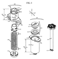
ここで図1を参照すると、着脱式シリンジマイクロポンプ(removable syringe micro pump)100(以下では、RSMP100という)が分解図に示されている。図示されているように、RSMP100は、主としてポンプハウジング102およびウェーブスプリング104で構成される。以下の説明によってさらに充分に理解されるように、RSMP100は、取り外し可能であるため、患者またはシリンジマイクロポンプの使用を望む者に別個に提供することができ、同じ者または別の者が、同じシリンジまたは別のシリンジに再使用することができる。
Here, referring to FIG. 1, a removable syringe micropump 100 (hereinafter referred to as RSMP100) is shown in an exploded view. As shown, the
このRSMP100のシステムおよび方法の説明を容易にするために、図面に示されているRSMP100の向きは、図1に示されている互いに直交する3つの軸を有する座標系を参照する。これらの軸は、RSMP100の中心に位置するように選択された座標系の原点において互いに交差するが、すべての図において、これらの軸は、説明の分かり易さおよび容易さのために、実際の位置からずらされて図示されている。 To facilitate the description of this RSMP100 system and method, the orientation of the RSMP100 shown in the drawings refers to a coordinate system with three axes orthogonal to each other shown in FIG. These axes intersect each other at the origin of the coordinate system chosen to be centered on the RSMP100, but in all figures these axes are actual for clarity and clarity of description. It is shown offset from the position.
ポンプハウジング102は、一部分が補強ベース108によって形成されてもよい第1の端部106を提供する。第1の端部106の反対側には、取り付け端部110が存在し、両者の間に少なくとも1つの側壁112が存在する。少なくとも1つの実施形態において、取り付け端部110は、1組のフランジ114を有する。
The
図示のように、少なくとも1つの実施形態において、ポンプハウジング102は、円筒形である。当然ながら、他の実施形態においては、円形以外にも、正方形、六角形、または幾何学的断面を有する構成のポンプハウジング102を提供することが、望ましいかもしれない。
As shown, in at least one embodiment, the
ポンプハウジング102の内部かつ第1の端部106の付近に、ウェーブスプリング104を受け入れてポンプハウジング102にしっかりと固定させるような構造および配置のベース116がある。少なくとも1つの実施形態において、ベース116は、ウェーブスプリング104を受け入れるような構造および配置の少なくとも一つのマウンティングタブ118を有する。
Inside the
図1に示されるように、ウェーブスプリング104は、伸長/弛緩位置にある。ウェーブスプリングは典型的には、ばね作用を提供するために追加されたウェーブをもつコイル状のフラットワイヤから作られている。ウェーブスプリングは一般にコイルスプリングと比べてばねの高さを50%減らすことができる。したがってウェーブスプリングは空間節約という独自の利点を提供する。さらに、張力下で圧縮されたウェーブスプリング104の高さは、伸長時のウェーブスプリング104の高さよりも大幅に小さい。
As shown in FIG. 1, the
ウェーブスプリングはまた伝統的なコイルスプリングに比べて、たわみの範囲にわたってより一貫性のある力を生成し、これにより、有利なことにRSMP100が動作に関して正確であることが可能になる。さらに、伝統的なコイルスプリングとは違って、ウェーブスプリング104は圧縮された時、ねじりの負荷を生成しない。したがってウェーブスプリング104は圧縮が解放される間、回転力を与えない。ウェーブスプリング104は典型的には比較的短い移動距離を要求する応用例で利用されるが、ウェーブスプリング104は50ミリ以上の移動を提供するように製造されてもよい。少なくともある実施形態において、複数のウェーブスプリングを直列に使用してもよい。
Wave springs also generate more consistent forces over a range of deflections compared to traditional coil springs, which advantageously allows the RSMP100 to be accurate in terms of operation. Moreover, unlike traditional coil springs, wave springs 104 do not generate a torsional load when compressed. Therefore, the
ウェーブスプリングの剛性は、ばね材料の厚さおよびタイプだけでなく、ばねの1回転あたりのウェーブの数によっても決まる。したがって、RSMP100の実施形態は、異なる液体を収容してシリンジから送出することができるように、異なるばね力の特徴をもたせて設計されてもよい。 The stiffness of a wave spring depends not only on the thickness and type of spring material, but also on the number of waves per revolution of the spring. Therefore, embodiments of RSMP100 may be designed with different spring force characteristics so that different liquids can be accommodated and delivered from the syringe.
少なくとも1つの実施形態において、ウェーブスプリング104の第1の端部120、すなわち近位端は、ベース116の少なくとも一部のあたりに配置され、マウンティングタブ118がウェーブスプリング104と係合する。したがって、ウェーブスプリング104の遠位端122は、ウェーブスプリング104が、圧縮された第1の位置から弛緩/伸長した第2の位置に移行するにつれてウェーブスプリング104の張力が解放されるとき、全体としてのベース116およびポンプハウジング102から遠ざかる方向に移動する。少なくとも1つの実施形態において、RSMP100は、ウェーブスプリング104の遠位端122の少なくとも一部を受ける終端駆動部124を含む。
In at least one embodiment, the
図1において、RSMP100の隣に、胴部128を有するシリンジ126が示されており、胴部128は、ノズル132と、シリンジ126の開放端136に隣接する1組のフィンガグリップ134との間にチャンバ130を画定する。プランジャシール138が、シールを維持しつつ、胴部128の内側に沿って摺動することができる、胴部128内の可動要素であると理解および認識される。
In FIG. 1, a
図示の構成など、いくつかの構成においては、プランジャシール138を、可動シールをもたらすために使用することができるゴム、シリコーン、または他の半弾性材料で概して構成されたシール要素142に結合されたピストン要素140で構成することができる。今回の検討の目的において、プランジャシール138は、1つの部品で形成されるか、あるいは複数の部品で形成されるかにかかわらず、この構成要素であると理解される。
In some configurations, such as the configuration shown, the
さらに、図1には、シリンジ126から取り出され、プランジャシール138から分離されたプランジャ144が示されている。プランジャ144が取り付けられると、操作者は、フィンガグリップ134の周囲に指を係合させ、プランジャシール138をチャンバ130内においてノズル132の上方の位置からノズル132に向かって押し込むためにプランジャ144を使用することができる。逆もまた真である。
Further, FIG. 1 shows the
図1において理解されるように、プランジャ144は、矩形のフランジなどの、位置合わせを明確にする取り付け要素152を有する。同様に、プランジャシール138は、矩形の受け部などの対応する嵌合取り付け要素154を有する。したがって、少なくとも1つの実施形態においては、プランジャ144の、プランジャシール138との係合およびプランジャシール138からの切り離しは、プランジャの取り付け要素152がプランジャシールの嵌合取り付け要素154内に配置されているときに、ねじり動作によって行われる。図示されていないさらに別の実施形態においては、プランジャ144は、プランジャシール138に結合する取り付け要素を解放するプッシュまたはプル機構を有する。
As will be appreciated in FIG. 1, the
プランジャ144がプランジャシール138に取り付けられると、操作者は、プランジャ144によってプランジャシール138をフィンガグリップ134に向かってノズル132から引き離すことができる。この動作は、胴部128の内部に真空を生じさせ、シリンジ126が、ノズル132を通して流体溶液または気体を吸い上げ、ノズル132とプランジャシール138との間の胴部128を実質的に満たすことを可能にする。
When the
図1に関して、図示のように、プランジャ144の長さが実際にはシリンジ126の胴部128よりも長いことを、理解すべきである。しかしながら、プランジャ144は取り外し可能であるため、プランジャシール138がフィンガグリップ134に隣接して配置され、あるいは適切であると考えられる胴部128内の他の所望の場所のどこに配置されても、プランジャ144が取り外されたとき、シリンジ126の有効長は、ほぼ胴部128およびノズル132の有効長である。
With respect to FIG. 1, it should be understood that, as shown, the length of the
再びRSMP100に目を向け、より具体的にはポンプハウジング102の取り付け端部110に目を向けると、フランジ114が、シリンジ126のフィンガグリップ134に係合するような構造および配置であることを、理解できるであろう。さらに、ポンプハウジング102がフィンガグリップ134に隣接してシリンジ126の開放端136に被せられたとき、操作者は、これらの部品を互いに対して回転させて、フランジ114をフィンガグリップ134に係合させる。フィンガグリップ134が、人間の操作者の指のためのてこの点を提供するのとほぼ同じ方法で、フィンガグリップ134は、RSMP100のためのてこの点を提供する。
Looking again at the RSMP100, more specifically at the mounting
少なくとも1つの実施形態において、フランジ114は、実質的にフィンガグリップ134のサイズおよび形状のはめ込み凹部を備えることができ、したがって、所定の位置に回転させられたとき、フィンガグリップ134が凹部に受け入れられ、RSMP100が所定の位置に固定される。1つ以上の追加のばね(図示せず)が、RSMP100のシリンジ126からの意図せぬ分離に抗してフィンガグリップ134をフランジの凹部または部屋にさらに係合させるためにポンプハウジング102とシリンジ126との間に分離力をもたらすことができる。
In at least one embodiment, the
さらに、ウェーブスプリング104の終端駆動部124が、係合したシリンジ126のプランジャシール138と係合するような構造および配置を有することを、理解すべきである。随意選択の実施形態において、ウェーブスプリング104の遠位端122は、プランジャシール138に直接係合してもよい。
Further, it should be understood that the
圧縮されたウェーブスプリング104が解放されると、張力の解放により、ウェーブスプリング104は、ポンプハウジング102から外へ終端駆動部124に対して伸び、その結果、プランジャシール138を駆動する。ポンプハウジング102はフランジ114によってフィンガグリップ134に対して所定の位置に固定されているため、ウェーブスプリング104が、圧縮された第1の位置から弛緩/伸長した第2の位置に伸びると、遠位端122を終端駆動部124に対して駆動し、それに応じてプランジャシール138をノズル132に向かって駆動する。
When the compressed
さらに、ウェーブスプリング104が、伝統的なプランジャ144の代わりに有利に動作することを、理解および認識すべきである。
In addition, it should be understood and recognized that the
図1にさらに示されるように、ポンプハウジング102は、側壁112に沿った寸法HD146を有する。少なくとも1つの実施形態において、この寸法HD146は、シリングの長さSL148よりも短い。少なくとも1つの実施形態において、この寸法HD146は、シリングの長さSL148の約半分であってもよい。少なくとも1つの特定の実施形態において、この寸法HD146は、シリングの長さSL148の半分より小さい。さらに、RSMP100はコンパクトであり、装着された時、シリンジ126の全長に実質的に何も加えないことを理解および認識すべきである。
As further shown in FIG. 1, the
より具体的には、側壁112の寸法が、シリンジ126の長さよりも短いことを、理解および認識すべきである。少なくとも1つの実施形態において、ポンプハウジング102の側壁112の寸法は、シリンジ126の長さの半分未満である。少なくとも1つの実施形態において、ポンプハウジング102の側壁112の寸法は、シリンジ126の長さの1/3未満である。別の少なくとも1つの実施形態において、ポンプハウジング102の側壁112の寸法は、シリンジ126の長さの1/4未満である。さらに、RSMP100がコンパクトであり、取り付けられたときにシリンジ126の全長を実質的に増やさないことを、理解および認識できるであろう。
More specifically, it should be understood and recognized that the dimensions of the
またさらに、プランジャ144が取り外されると、シリンジ126に結合したRSMP100を、注入治療セッションの最中に、個人のポケット、財布、パック、または他の空間に、おおむね任意の向きにて配置することができる。ウェーブスプリング104の運動は、完全にポンプハウジング102およびシリンジ126の胴部128の範囲内であるため、外部の物品に引っ掛かったり、あるいは外部の物品によって抑止されたりすることがない。
Furthermore, once the
RSMP100はプランジャ144を使用せずに有利に動作可能であるが、少なくとも1つの実施形態において、RSMP100、より具体的にはポンプハウジング102は、プランジャ144がRSMP100を直接通過してプランジャシール138に係合できるよう、中央開口150を提供する。したがって、プランジャ144を使用し、プランジャシール138を使用してウェーブスプリング104を圧縮された第1の位置に引き戻し、プランジャシール138を再度前方に駆動するために使用できる状態にすることで、RSMP100をリセットすることができる。
The
少なくとも1つの実施形態において、RSMP100は、第1の位置に戻されたときにウェーブスプリング104を拘束するような構造および配置とされたウェーブスプリング104の拘束具156をさらに含むことができる。図1に示した典型的な実施形態においては、典型的な拘束具156が、遠位端122に近いウェーブスプリング104の縁に係合するスライドピンに結合する内部レバーを操作する押しボタンとして示されている。スライドピンは、ウェーブスプリング104の側面の溝またはスロットに随意選択的に係合することができる。あるいは、拘束具156は、ウェーブスプリング104の周囲で締められる調節可能な摩擦リングであってよい。当然ながら、本開示の教示の範囲内で、さまざまな機械的要素をウェーブスプリング104の拘束具156として使用できることを、理解および認識すべきである。
In at least one embodiment, the
図2A、図2B、および図2Cが、RSMP100で使用されるウェーブスプリング104の有利な性質の理解および認識に役立つさらなる図を提供する。より具体的には、図2Aにおいて、ウェーブスプリング104は、弛緩/伸長した第2の位置200にて示されている。この第2の位置200においてウェーブスプリングは弛緩した長さ寸法RL202を有する。
2A, 2B, and 2C provide additional diagrams to help understand and recognize the advantageous properties of the
圧縮力204を加えることによって、ウェーブスプリング104は、図2Bに示されるように、各コイルのウェーブ要素が圧縮されてコイル206が互いに垂直に積み重なるように圧縮される。これは、ウェーブスプリング104の圧縮された第1の位置208である。この状態において、ウェーブスプリング104は、矢印210によって示されるとおり、張力下にある。より具体的には、確立された張力は、ウェーブスプリング104が、圧縮された第1の位置208からひとたび解放されると、再び弛緩/伸長した第2の位置200に戻す伸長力210である。
By applying the
図2Bにおいて認識されるように、この第1の位置208においてウェーブスプリングは圧縮された長さ寸法CL212を有する。図示されるように、圧縮された長さ寸法CL212は、弛緩された長さ寸法RL202のほんの一部である。圧縮された長さ寸法CL212はポンプハウジング102の寸法HD146(図1参照)よりも小さいため、ウェーブスプリング104が第1の位置208にある時、ウェーブスプリング104は実質的にポンプハウジング102内に配置される。
As recognized in FIG. 2B, at this first position 208 the wave spring has a compressed length dimension CL212. As shown, the compressed length dimension CL212 is only a portion of the relaxed length dimension RL202. Since the compressed length dimension CL212 is smaller than the
図2Cに示されるように、ウェーブスプリング104のコイル206の性質は、ウェーブスプリング104が開いた中心214を有するようなものである。したがって、この開いた中心214によって、ウェーブスプリング104は、プランジャがポンプハウジング102の開口150を通って配置されるときに、プランジャ144がウェーブスプリング104を通過してプランジャシール138に係合することを許容することができる。
As shown in FIG. 2C, the nature of the
さらに、少なくとも1つの実施形態において、ウェーブスプリング104は、所定の時間期間にわたってシリンジ126から溶液を送出するように相関付けられた張力を有するように選択される。換言すると、第1の張力を有する第1のウェーブスプリング104を、第1の速度で溶液を送出するために使用できる一方で、第1の張力よりも小さい第2の張力を有する第2のウェーブスプリング104を、同じ溶液を第1の速度よりも遅い第2の速度で送出するために使用することができる。
Further, in at least one embodiment, the
少なくとも1つの実施形態において、ウェーブスプリング104は、シリンジ126の胴部128の内部の溶液のすべてが送出されることを保証するために、胴部128の長さに等しく、あるいは胴部128の長さをわずかに超える弛緩/伸長した第2の位置200を有するように選択される。また、ウェーブスプリング104が、図示されているように第1の位置208まで完全に圧縮される必要はないことも、理解および認識すべきである。
In at least one embodiment, the
実際、ウェーブスプリング104は、遠位端122がポンプハウジング102から延びつつ、ウェーブスプリング104の大部分がポンプハウジング102に実質的に戻るように圧縮することができる。さらに、圧縮された第1の位置208は、RSMP100が作動してプランジャシール138をノズル132に向かって駆動する前のRSMP100のポンプハウジング102に対するウェーブスプリング104の初期位置であると理解および認識される。
In fact, the
さらに、ウェーブスプリング104の拘束具156は、RSMP100をシリンジ126に取り付けることを可能にするが、ウェーブスプリング104の作動は、シリンジ126の胴部128の内部の溶液の注入が所望されるような時点まで遅延される。
Further, the restraint 156 of the
図3A、図3B、図3C、および図3Dは、それぞれRSMP100の正面図、側面図、底面図、および斜視図を提供している。図示されている各々の図において、ウェーブスプリング104は、ポンプハウジング102内の圧縮された第1の位置208に示されている。図3Aにおいて、ポンプハウジング102の高さHD146に対するウェーブスプリング104の圧縮された長さ寸法CL212も、さらに充分に理解することができる。実際に、図3A、図3B、図3C、および図3Dに関して、RSMP100の構成要素を、シリンジが存在しない別個のRSMP100を構成するものとして理解できるため、RSMP100の取り外し可能な性質をさらに理解することができる。
3A, 3B, 3C, and 3D provide a front view, a side view, a bottom view, and a perspective view of the
要約すると、少なくとも1つの実施形態において、第1の端部106、第1の端部106の反対側の取り付け端部110、および両者の間の少なくとも1つの側壁112を有するとともに、第1の端部106に近接したベース116を有するポンプハウジングであって、取り付け端部110は、シリンジ126に一時的に係合するような構造および配置の取り付け具114を有するポンプハウジング102と、ハウジングの内部に収められ、ベース116に近接して取り付けられたウェーブスプリング104とを含み、ウェーブスプリング104は、ウェーブスプリング104が張力下で圧縮され、ウェーブスプリング104の初期高さがポンプハウジング102内に配置される、第1の位置208と、張力の解放によってウェーブスプリング104が通常はポンプハウジング102から遠ざかる方向に伸びる第2の伸長した位置200とを有し、ウェーブスプリング104は、係合したシリンジ126の胴部128内を通過するように予め選択された直径を有し、ウェーブスプリング104は、係合したシリンジ126のプランジャシール138と係合するような構造および配置の遠位端122をさらに有し、第1の位置208と第2の位置200との間の張力の解放は、ウェーブスプリング104の遠位端122がプランジャシール138をシリンジ126のノズル132に向かって移動させることを可能にする、RSMP100が提供される。
In summary, in at least one embodiment, the
さらに、別の実施形態を、ベース116が設けられている第1の端部106、および第1の端部106の反対側の取り付け端部110を有する円筒形のポンプハウジング102であって、取り付け端部110は、円筒形のポンプハウジング102を一時的に取り付けることができるシリンジ126によって提供される1組のフィンガグリップ134に一時的に結合するような構造および配置の少なくとも1つのフランジ114を提供し、円筒形のポンプ100は、中心の長手軸を有する円筒形のポンプハウジング102と、ベース108に近接して長手軸を中心にしてポンプハウジング102内に配置された少なくとも1つのウェーブスプリング104とを含んでおり、ウェーブスプリング104は、第1の張力下の位置208をもたらすようにウェーブスプリング104の遠位端122が圧縮されるときに円筒形のポンプ102の内側に収まるように軸方向に圧縮可能であり、ウェーブスプリング104の高さは、第1の張力下の位置208まで圧縮された時、円筒形のポンプハウジング102の長さとほぼ同じであり、ウェーブスプリング104は、シリンジ126の胴部128の内側で摺動するために充分な直径を有するようにさらに選択され、ウェーブスプリング104の遠位端122は、係合したシリンジ126のプランジャシール138と係合するような構造および配置である、RSMP100と要約することができる。
Yet another embodiment is a
図4Aおよび図4Bは、少なくとも1つの実施形態によるシリンジ126に係合したRSMP100について、組み立てられた状態の斜視図および対応する切断図を提供している。さらに、図4Aにおいて、RSMP100は、ポンプハウジング102のフランジ114がシリンジ126のフィンガグリップ134に係合するようにシリンジ126上に配置されている。図4Aに関して、RSMP100が取り付けられたシリンジ126の全長が、シリンジ126だけの長さと比べてわずかに長いに過ぎないことも、理解すべきである。
4A and 4B provide a perspective view of the assembled state and a corresponding cut-out view of the RSMP100 engaged with the
また、外側の図である図4Aに関して、組み立てられたRSMP100およびシリンジ126のアセンブリ内部のウェーブスプリング104の状態が、とりわけシリンジ126の胴部128が不透明である場合に、明らかに見える必要はないことを、理解すべきである。
Also, with respect to FIG. 4A, which is the outer view, the state of the
長手軸400に沿った切断図を示している図4Bにおいて、ウェーブスプリング104が、ポンプハウジング102内の第1の圧縮された位置から第2の弛緩した位置に伸びており、この位置の変化の間に放出された力の作用により、プランジャシール138が胴部128の全長にわたって押し下げられ、ここではプランジャシール138がノズル132に近接していることが分かる。
In FIG. 4B, which shows a cut view along the
図5Aおよび図5Bは、シリンジ126に係合したRSMP100について、同様に組み立てられた状態の斜視図および対応する切断図を提供しており、ここでは、少なくとも1つの実施形態に従ってポンプハウジング102の開口150を通って配置されたプランジャ144がさらに示されている。上述のように、RSMP100の典型的な使用の間、プランジャが、動作に必要な全体としての空間を最小限にするとともに、何らかの異物によってプランジャが動かなくなり、あるいは他のかたちで拘束され、結果としてRSMP100の動作が妨げられる可能性をなくすために、取り外されることを理解および認識すべきである。
5A and 5B provide a similarly assembled perspective view and a corresponding cut-out view of the RPMP100 engaged in the
図5Aおよび図5Bに示されるように、プランジャ144を、プランジャシール138に係合して、プランジャシール138をノズル132からフィンガグリップ134に向かって引き戻すように、RSMP100を通って配置することができる。したがって、プランジャ144を、ウェーブスプリングを圧縮された第1の位置208に戻すことによってRSMP100をリセットするために使用することができる。さらに、伝統的なシリンジと同様に、プランジャ144を引き戻すことによって、シリンジ126のチャンバ内に真空が生成され、したがって流体をソースリザーバからシリンジ126に引き込むことができる。さらに、プランジャ144を、シリンジ126のプライミングおよびRSMP100のリセットの両方に使用することができる。
As shown in FIGS. 5A and 5B, the
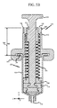
図6A、図6B、図7A、および図7Bは、使用時のRSMP100を示す側面断面図を提供している。より具体的には、図6Aは、プランジャシール138がフィンガグリップ134に隣接して位置している状態でシリンジ126に取り付けられたときのRSMP100の初期状態に対応する。実際の使用においては、ドット600で表されている、注入療法用などの流体または薬剤が、プランジャシール138とノズル132との間のチャンバ130内に存在すると考えられる。
6A, 6B, 7A, and 7B provide side sectional views showing RSMP100 in use. More specifically, FIG. 6A corresponds to the initial state of the
図6Bにおいては、RSMP100が作動し、ウェーブスプリング104が圧縮された/張力下の第1の位置208から解放され、終端駆動部124によってプランジャシール138に係合して、プランジャシール138をノズル132に向かって胴部128に沿った距離の約3分の1だけ移動させることで、流体600を送出している。実際の使用において、シリンジ126、より具体的にはノズル132は、説明を簡単にするために図示されていない配管または他の送出導管に接続されると考えられる。
In FIG. 6B, the
図7Aにおいては、RSMP100が動作を続け、ここではウェーブスプリング104がプランジャシール138をノズル132に向かって胴部128に沿った距離の約3分の2だけ移動させることで、流体600をさらに送出している。
In FIG. 7A, the
図7Bにおいては、ここでは実質的にすべての流体がシリンジ126から送出されるように、ウェーブスプリング104は、ここではプランジャシール138を実質的に胴部128の端部まで駆動し、RSMP100は動作を停止している。
In FIG. 7B, the
さらに、図6A、図6B、図7A、および図7Bに関して、ウェーブスプリング104の伸長、したがってプランジャシール138の前進は、ウェーブスプリング104が伸長/弛緩した第2の位置に到達するか、プランジャシール138が胴部128の端部にぶつかるか、あるいは拘束機構(図示せず)が係合してウェーブスプリング104のさらなる伸長を防止するまで続く。少なくとも1つの実施形態において、ウェーブスプリング104は、シリンジ126の胴部128の内部の溶液のすべてが送出されることを保証するために、完全に伸長した状態で、ウェーブスプリング104の長さが胴部128の長さに等しく、あるいは胴部128の長さをわずかに超えるように選択される。
Further, with respect to FIGS. 6A, 6B, 7A, and 7B, the extension of the
さらに、とりわけ図6A、図6B、図7A、および図7Bに明らかなように、ウェーブスプリング104の動きは、完全にRSMP100およびシリンジ126の胴部128の内部で生じる。さらに、結合されたRSMP100およびシリンジ126の寸法について、動作中に外的変化がなく、例えばプランジャ144が引っ掛かったり、邪魔になったりすることがない。また、例示的な図6A、図6B、図7A、および図7Bが、例えばシリンジ全体など、フィンガグリップ134に近接する出発点からノズル132に近接する胴部128の端部までプランジャシール138を駆動するためのRSMP100の使用を示しているが、RSMP100が、シリンジ全体よりも少ない初期開始容積を有するシリンジにおける使用にも同様に適用可能かつ適していることを理解および認識すべきであることに、留意されたい。
Furthermore, the movement of the
RSMP100およびシリンジ126が小型でコンパクトであるという性質によって、この組み合わされた構造物をポケットに入れた状態で注入を行うことを容易にすることができる。さらに、ウェーブスプリング104の動作が張力の機械的解放であるため、RSMP100の動作が向きに依存しないことを理解および認識できるであろう。
The small size and compact nature of the RSMP100 and
輸送のために、RSMP100をシリンジ126の胴部128に取り付け、プランジャ144をポンプハウジング102の開口150を通って挿入して、プランジャシール138に据え付けてもよく、プランジャシール138は、ノズル132に隣接するシリンジ126の底部に対して配置することができる。したがって、シリンジ126およびRSMP100は、コンパクトなシステムである。RSMP100の使用が所望されるとき、プランジャ144を引き出すことによってプランジャシール138を引き戻すことができ、このプロセス中に、次に所望される溶液で胴部128を満たすことができる。
For transport, the
プランジャシール138が所望の量の溶液をもたらすための充分な地点に適切に配置された状態で、プランジャ144をプランジャシール138から切り離し、廃棄することができる。ここではプランジャ144が取り外されるので、RSMP100およびシリンジ126は、再び好都合にコンパクトなシステムである。すでに述べたように、サイズの外的変化がないように、ウェーブスプリング104の動作は完全に内部である。
The
RSMP100の以上の説明に関して、上述した、RSMP100の取り外し可能な性質を、ここではさらに充分に理解することができる。実際に、RSMP100は、取り外し可能であるだけでなく、再使用可能でもある。すなわち、RSMP100をリセットし、プライミングされ、シリンジポンプを備えずに届けられた新たなシリンジに取り付けることができ、したがって、これらに限られるわけではないが輸送、保管、材料、および使用の教育などの部門の範囲にまたがる節約が可能になる。ひとたび患者または当事者がRSMP100を使い終えると、そのRSMP100を新たな当事者のために再使用することも可能である。またさらに、RSMP100を複数の者が共有し、当然ながら異なる時点においてRSMP100を使用してもよい。 With respect to the above description of the RSMP100, the removable properties of the RSMP100 described above can be more fully understood here. In fact, the RSMP100 is not only removable, but also reusable. That is, the RSMP100 can be reset and attached to new syringes that have been primed and delivered without a syringe pump, and thus, but not limited to, transportation, storage, materials, and usage education, etc. Allows savings across departments. Once the patient or party has finished using the RSMP100, the RSMP100 can be reused for a new party. Furthermore, RSMP100 may be shared by a plurality of persons, and of course, RSMP100 may be used at different time points.
RSMP100の実施形態を説明したので、次に、RSMP100を使用する少なくとも1つの方法800に関する他の実施形態を、上述の例示に関し、特に図8に関して説明する。説明される方法700は、必ずしも本明細書に記載される順序で実行される必要はなく、これは、RSMP100を使用するための1つの方法の単なる例示に過ぎないことを、理解できるであろう。
Having described the embodiments of RSMP100, then other embodiments relating to at least one
一般に、使用方法800は、ノズル132と1組のフィンガグリップ134との間に延びる胴部128を有するシリンジ126を用意することで始まる(ブロック802)。簡略化のために、プランジャシール138が、胴部128の内部かつフィンガグリップ134の付近に配置され、プランジャシール138とノズル132との間に溶液が配置されていると仮定する。さらに、これは、患者に注入するための溶液をもたらすためにすぐに使用することができる状態のシリンジ126である。
In general,
次に、フィンガグリップ134に係合するような構造および配置の1組のフランジ114を有するRSMP100を用意する(ブロック804)。さらに、用意されるRSMP100は、上述のように、主としてポンプハウジング102およびウェーブスプリング104で構成される。方法800は、次に、フランジ114をフィンガグリップ134の周囲に配置することによってRSMP100をシリンジ126に結合させる(ブロック806)。
Next, an
その後、ウェーブスプリング104が解放され、シリンジ126のプランジャシール138に係合して、プランジャシール138をノズル132に向かって駆動し、溶液をシリンジ126から送出する(ブロック808)。
The
RSMP100および関連づけられた使用方法700に関する上記の説明に関して、少なくとも1つの実施形態においてウェーブスプリング104は、図示しない少なくとも1つの渦巻きばねによって覆われてもよい。より具体的には、ウェーブスプリングを保護し、圧縮および伸長の間、よじれないことを保証するのを助けるために、1以上の渦巻きばねを少なくとも部分的に用いてもよい。さらに別の実施形態において、ウェーブスプリング104は、シリンジ126のプランジャシール138と相互作用してプランジャシール138をノズル132に向かって駆動するように整列された配置で渦巻きばねと結合してもよい。さらに、1以上の渦巻きばねが、ウェーブスプリング104の周りの鞘として、あるいはウェーブスプリング104に配置される付加的ばね要素として少なくとも部分的に作用するであろうが、この1以上の渦巻きばねは「渦巻きばねを備える着脱式シリンジマイクロポンプのためのシステムおよび方法」という名称の米国特許出願第15/291,758号(この米国特許出願の開示は、参照によって本明細書に組み込まれる)に記載された着脱式マイクロポンプに用いられる渦巻きばねであってもよい。
With respect to the above description of the
本明細書の範囲から逸脱することなく、上述の方法、システム、および構造において変更を行うことができる。したがって、以上の説明に含まれる事項、および/または添付の図面に示されている事項は、例示として解釈されるべきであり、限定の意味で解釈されてはならないことに留意されたい。実際、当業者にとって明らかであるように、他の多くの実施形態が好適に可能である。本明細書で論じた実施形態は、以下の特許請求の範囲を限定するものではなく、以下の特許請求の範囲は、本明細書で論じた実施形態に限られず、むしろ特許請求の範囲の文言および均等論によってのみ限定される。 Changes can be made in the methods, systems, and structures described above without departing from the scope of this specification. Therefore, it should be noted that the matters contained in the above description and / or the matters shown in the accompanying drawings should be construed as examples and not in a limited sense. In fact, many other embodiments are preferably possible, as will be apparent to those skilled in the art. The embodiments discussed herein do not limit the scope of the following claims, and the scope of the following claims is not limited to the embodiments discussed herein, but rather the wording of the scope of claims. And limited only by the doctrine of equivalents.
Claims (38)
第1の端部、該第1の端部の反対側の取り付け端部、両者の間の少なくとも1つの側壁、および開口を有するとともに、前記第1の端部に近接したベースを有するポンプハウジングであって、前記取り付け端部は、シリンジに一時的に係合するような構造および配置の取り付け具を有する、ポンプハウジングと、
前記ハウジングの内部に収められ、前記ベースに近接して取り付けられたウェーブスプリングと、
取り付け要素を有するプランジャと、
を備え、
前記ウェーブスプリングは、該ウェーブスプリングが張力下で圧縮され、該ウェーブスプリングの初期高さがポンプハウジング内に配置される、第1の位置と、張力の解放によって該ウェーブスプリングが通常は前記ポンプハウジングから遠ざかる方向に伸びる第2の伸長した位置とを有し、前記ウェーブスプリングは、係合した前記シリンジの胴部内を通過するように予め選択された直径を有し、前記ウェーブスプリングは、係合した前記シリンジのプランジャシールと係合するような構造および配置の遠位端をさらに有し、前記第1の位置と前記第2の位置との間の張力の解放は、前記ウェーブスプリングの前記遠位端が前記プランジャシールを前記シリンジのノズルに向かって移動させることを可能にし、
前記プランジャは、前記取り付け具が前記シリンジに係合した状態で、前記開口を通って前記シリンジの内部に挿入されるような構造を有し、
前記取り付け要素は、前記プランジャが前記シリンジの内部に挿入された状態で、前記プランジャシールに取り外し可能に係合するような構造を有する、
着脱式シリンジマイクロポンプのためのシステム。 A system for removable syringe micropumps with wave springs
First end, opposite the attachment end of the first end, at least one side wall between the two persons, and which has an opening, the pump housing having a base proximate to the first end The mounting end is a pump housing and a mounting tool having a structure and arrangement that temporarily engages the syringe.
A wave spring housed inside the housing and mounted close to the base ,
Plunger with mounting elements and
With
The wave spring is compressed under tension and the initial height of the wave spring is located in the pump housing, the first position and the release of the tension causes the wave spring to be normally said to the pump housing. It has a second extended position extending away from the wave spring, the wave spring having a diameter preselected to pass through the body of the engaged syringe, and the wave spring engaging. It further has a distal end of structure and arrangement that engages with the plunger seal of the syringe, and the release of tension between the first position and the second position is the distance of the wave spring. proximal end is it possible to move toward the plunger seal nozzles of the syringe,
The plunger has a structure in which the fitting is inserted into the inside of the syringe through the opening in a state of being engaged with the syringe.
The mounting element has a structure such that the plunger is removably engaged with the plunger seal while being inserted inside the syringe.
Detachable syringe A system for micropumps.
開口、ベースが設けられている第1の端部、および該第1の端部の反対側の取り付け端部を有する円筒形のポンプハウジングであって、前記取り付け端部は、該円筒形のポンプハウジングを一時的に取り付けることができるシリンジによって提供される1組のフィンガグリップに一時的に結合するような構造および配置の少なくとも1つのフランジを提供し、該円筒形のポンプハウジングは、中心の長手軸を有する円筒形のポンプハウジングと、
前記ベースに近接して前記長手軸を中心にして前記ポンプハウジング内に配置された少なくとも1つのウェーブスプリングと、
取り付け要素を有するプランジャと、
を備えており、
前記ウェーブスプリングは、第1の張力下の位置をもたらすように該ウェーブスプリングの遠位端が圧縮されるときに前記円筒形のポンプの内側に収まるように軸方向に圧縮可能であり、前記ウェーブスプリングの高さは、前記第1の張力下の位置まで圧縮された時、前記円筒形のポンプハウジングの長さとほぼ同じであり、前記ウェーブスプリングは、シリンジの胴部の内側で摺動するために充分な直径を有するようにさらに選択され、前記ウェーブスプリングの前記遠位端は、係合した前記シリンジのプランジャシールと係合するような構造および配置であり、
前記プランジャは、前記フランジが前記フィンガグリップに結合した状態で、前記開口を通って前記シリンジの内部に挿入されるような構造を有し、
前記取り付け要素は、前記プランジャが前記シリンジの内部に挿入された状態で、前記プランジャシールに取り外し可能に係合するような構造を有する、
着脱式シリンジマイクロポンプのためのシステム。 A system for removable syringe micropumps with wave springs
A cylindrical pump housing having an opening, a first end provided with a base, and a mounting end opposite the first end, wherein the mounting end is the cylindrical pump. The cylindrical pump housing provides a central length to provide at least one flange with a structure and arrangement that temporarily connects to a pair of finger grips provided by a syringe to which the housing can be temporarily attached. Cylindrical pump housing with shaft and
With at least one wave spring located in the pump housing close to the base and centered on the longitudinal axis .
Plunger with mounting elements and
Is equipped with
The wave spring is axially compressible so that it fits inside the cylindrical pump when the distal end of the wave spring is compressed to provide a position under first tension. The height of the spring is approximately the same as the length of the cylindrical pump housing when compressed to the position under the first tension, because the wave spring slides inside the body of the syringe. is further selected to have a diameter sufficient, the distal end of the wave spring, Ri construction and arrangement der such that the plunger seal and the engagement of the syringe engaged,
The plunger has a structure such that the flange is inserted into the inside of the syringe through the opening in a state of being coupled to the finger grip.
The mounting element has a structure such that the plunger is removably engaged with the plunger seal while being inserted inside the syringe.
Detachable syringe A system for micropumps.
ノズルと1組のフィンガグリップとの間に延びる胴部、および前記胴部内に前記フィンガグリップに近接して配置されたプランジャシールを有し、前記プランジャシールと前記ノズルとの間に溶液が配置されているシリンジと、
開口を有する円筒形のポンプハウジング、ウェーブスプリング、およびウェーブスプリング拘束具を含む、前記シリンジに取り付け可能な着脱式シリンジマイクロポンプと、
取り付け要素を有するプランジャと、を備え、
前記円筒形のポンプハウジングは、ベースを備える第1の端部、および該第1の端部の反対側の取り付け端部を有し、前記取り付け端部は、前記シリンジの前記フィンガグリップに一時的に結合するような構造および配置の少なくとも1つのフランジを提供し、前記円筒形のポンプハウジングは、中心の長手軸を有しており、
前記ウェーブスプリングは、前記ベースに近接して前記長手軸を中心にして前記円筒形のポンプハウジング内に配置され、前記ウェーブスプリングは、張力のかかった第1の位置をもたらすように該ウェーブスプリングの遠位端が圧縮されるときに前記円筒形のポンプの内側に収まるように圧縮可能であり、前記ウェーブスプリングの高さは、前記円筒形のポンプハウジングの長さとほぼ同じであり、前記ウェーブスプリングは、前記シリンジの前記胴部の内側で摺動するために充分な直径を有するようにさらに選択され、前記ウェーブスプリングの前記遠位端は、係合したシリンジのプランジャシールと係合するような構造および配置であり、
前記ウェーブスプリング拘束具は、前記ウェーブスプリングの前記遠位端が前記シリンジの前記プランジャシールと係合することを可能とするために解除可能であり、操作者によって解除されるまで前記ウェーブスプリングを初期の張力位置に保持するような構造および配置であり、
前記ウェーブスプリングは、前記ウェーブスプリング拘束具の解除による前記第1の位置からの張力の解放によって、前記ウェーブスプリングの前記遠位端で前記プランジャシールを前記シリンジの前記ノズルに向かって移動させることにより、前記シリンジからの溶液の送出を可能とし、
前記プランジャは、前記フランジが前記フィンガグリップに結合した状態で、前記開口を通って前記シリンジの内部に挿入されるような構造を有し、
前記取り付け要素は、前記プランジャが前記シリンジの内部に挿入された状態で、前記プランジャシールに取り外し可能に係合するような構造を有する、
システム。 A system for a removable syringe micropump with a wave spring to deliver a solution from a syringe .
It has a body extending between a nozzle and a set of finger grips, and a plunger seal located in the body close to the finger grip, and a solution is arranged between the plunger seal and the nozzle. and the syringe is,
Cylindrical pump housing having an opening, wave spring, and a wave spring restraint, and removable syringe micropumps attachable to the syringe,
With a plunger with mounting elements,
The cylindrical pump housing has a first end with a base and a mounting end opposite the first end, the mounting end being temporary to the flange grip of the syringe. The cylindrical pump housing has a central longitudinal axis and provides at least one flange of construction and arrangement such that it couples to.
The wave spring is located in the cylindrical pump housing close to the base and centered on the longitudinal axis, and the wave spring of the wave spring provides a tensioned first position. When the distal end is compressed, it can be compressed to fit inside the cylindrical pump, the height of the wave spring is approximately the same as the length of the cylindrical pump housing, and the wave spring. Is further selected to have a diameter sufficient to slide inside the body of the syringe so that the distal end of the wave spring engages the plunger seal of the engaged syringe. Structure and arrangement,
The wave spring restraint can be disengaged to allow the distal end of the wave spring to engage the plunger seal of the syringe , initializing the wave spring until disengaged by the operator. construction and arrangement der such as holding the tension position is,
The wave spring is released by releasing the tension from the first position by releasing the wave spring restraint, thereby moving the plunger seal toward the nozzle of the syringe at the distal end of the wave spring. , to allow the delivery of the solution from the syringe,
The plunger has a structure such that the flange is inserted into the inside of the syringe through the opening in a state of being coupled to the finger grip.
The mounting element has a structure such that the plunger is removably engaged with the plunger seal while being inserted inside the syringe.
System .
Applications Claiming Priority (5)
| Application Number | Priority Date | Filing Date | Title |
|---|---|---|---|
| US201662407376P | 2016-10-12 | 2016-10-12 | |
| US62/407,376 | 2016-10-12 | ||
| US15/729,896 | 2017-10-11 | ||
| US15/729,896 US10576199B2 (en) | 2016-10-12 | 2017-10-11 | System and method for a syringe micro pump with wave spring |
| PCT/US2017/056170 WO2018071561A1 (en) | 2016-10-12 | 2017-10-11 | System and method for a syringe micro pump with wave spring |
Publications (2)
| Publication Number | Publication Date |
|---|---|
| JP2019530536A JP2019530536A (en) | 2019-10-24 |
| JP6963607B2 true JP6963607B2 (en) | 2021-11-10 |
Family
ID=61829846
Family Applications (1)
| Application Number | Title | Priority Date | Filing Date |
|---|---|---|---|
| JP2019520137A Active JP6963607B2 (en) | 2016-10-12 | 2017-10-11 | Systems and methods for syringe micropumps with wave springs |
Country Status (6)
| Country | Link |
|---|---|
| US (1) | US10576199B2 (en) |
| EP (1) | EP3525846B1 (en) |
| JP (1) | JP6963607B2 (en) |
| CA (1) | CA3039462C (en) |
| ES (1) | ES2895089T3 (en) |
| WO (1) | WO2018071561A1 (en) |
Families Citing this family (8)
| Publication number | Priority date | Publication date | Assignee | Title |
|---|---|---|---|---|
| DK1762259T3 (en) | 2005-09-12 | 2011-01-03 | Unomedical As | Infusion set insertion device with a first and a second spring assembly |
| US10194938B2 (en) | 2011-03-14 | 2019-02-05 | UnoMedical, AS | Inserter system with transport protection |
| US11357912B2 (en) | 2016-01-19 | 2022-06-14 | Unomedical A/S | Cannula and infusion devices |
| GB2581514A (en) * | 2019-02-22 | 2020-08-26 | Danby Medical Ltd | Infusion Pump |
| EP3972672A4 (en) | 2019-05-20 | 2023-06-21 | Unomedical A/S | Rotatable infusion device and methods thereof |
| IT201900019460A1 (en) | 2019-10-21 | 2021-04-21 | Cane Spa | MANUALLY OPERATED MECHANICAL PUMP FOR DRUG INFUSION |
| US11278669B2 (en) | 2020-01-21 | 2022-03-22 | Repro Med Systems, Inc. | Gear-driven infusion assemblies, systems, and methods |
| DE102020118731A1 (en) * | 2020-07-15 | 2022-01-20 | Arlington Germany Gmbh | Sealing arrangement and control device for coolant flow in a cooling circuit of a vehicle |
Family Cites Families (18)
| Publication number | Priority date | Publication date | Assignee | Title |
|---|---|---|---|---|
| US4959056A (en) * | 1988-06-14 | 1990-09-25 | Wayne State University | Digital dispenser |
| US5100389A (en) * | 1988-06-21 | 1992-03-31 | Vaillancourt Vincent L | Ambulatory infusion pump |
| JPH0451966A (en) * | 1990-06-19 | 1992-02-20 | Toichi Ishikawa | Medical fluid continuous injector |
| US5383858B1 (en) * | 1992-08-17 | 1996-10-29 | Medrad Inc | Front-loading medical injector and syringe for use therewith |
| US5656034A (en) | 1995-03-31 | 1997-08-12 | Perkin Elmer Corp | High-pressure micro-volume syringe pump |
| US6019747A (en) * | 1997-10-21 | 2000-02-01 | I-Flow Corporation | Spring-actuated infusion syringe |
| EP1146922A4 (en) * | 1998-12-29 | 2004-09-08 | Mckinley Medical Lllp | Spring-powered infusion pump |
| US6610030B1 (en) | 1999-07-20 | 2003-08-26 | Anthony Baxter | Bilateral syringe tethered remote micro-pump |
| US6802892B2 (en) | 1999-09-16 | 2004-10-12 | Vasogen Ireland Limited | Apparatus and process for conditioning organic fluid |
| EP1232763A1 (en) * | 2001-02-14 | 2002-08-21 | Sergio Restelli | Disposable syringe |
| MY139059A (en) * | 2002-06-24 | 2009-08-28 | Alza Corp | Reusable, spring driven autoinjector |
| US7220245B2 (en) * | 2004-05-26 | 2007-05-22 | Kriesel Marshall S | Infusion apparatus |
| WO2006051539A2 (en) * | 2004-11-12 | 2006-05-18 | Shaul Ozeri | A miniature infusion pump for a controlled delivery of medication |
| FI1850892T4 (en) | 2005-01-24 | 2023-08-31 | Prefilled needle assisted syringe jet injector | |
| CN102612381B (en) | 2009-03-20 | 2015-09-09 | 安塔瑞斯制药公司 | Hazardous agents injected system |
| US20110087173A1 (en) | 2009-10-12 | 2011-04-14 | Sibbitt Jr Wilmer L | Automatic syringes |
| AU2013370583A1 (en) * | 2012-12-24 | 2015-07-02 | Fresenius Medical Care Holdings, Inc. | Portable dialysis machine with improved reservoir heating system |
| JP5755703B2 (en) * | 2013-10-18 | 2015-07-29 | 株式会社根本杏林堂 | Syringe |
-
2017
- 2017-10-11 WO PCT/US2017/056170 patent/WO2018071561A1/en unknown
- 2017-10-11 CA CA3039462A patent/CA3039462C/en active Active
- 2017-10-11 EP EP17861006.9A patent/EP3525846B1/en active Active
- 2017-10-11 US US15/729,896 patent/US10576199B2/en active Active
- 2017-10-11 ES ES17861006T patent/ES2895089T3/en active Active
- 2017-10-11 JP JP2019520137A patent/JP6963607B2/en active Active
Also Published As
| Publication number | Publication date |
|---|---|
| JP2019530536A (en) | 2019-10-24 |
| EP3525846A4 (en) | 2020-05-13 |
| EP3525846B1 (en) | 2021-09-01 |
| US10576199B2 (en) | 2020-03-03 |
| US20180099086A1 (en) | 2018-04-12 |
| WO2018071561A1 (en) | 2018-04-19 |
| EP3525846A1 (en) | 2019-08-21 |
| CA3039462C (en) | 2021-01-26 |
| ES2895089T3 (en) | 2022-02-17 |
| CA3039462A1 (en) | 2018-04-19 |
Similar Documents
| Publication | Publication Date | Title |
|---|---|---|
| JP6963607B2 (en) | Systems and methods for syringe micropumps with wave springs | |
| US11027059B2 (en) | Spring force assembly for biasing or actuating stoppers of syringes, injection pen cartridges and the like | |
| US10406282B2 (en) | System and method for a syringe micro pump with volute spring | |
| EP2665501B1 (en) | Automatic injection device with pneumatic damping | |
| EP2162170B1 (en) | One shot injector with dual springs | |
| US10022501B2 (en) | Medicament delivery device | |
| JP2008541931A5 (en) | ||
| TW201023931A (en) | Medication delivery device and method for operating a medication delivery device | |
| TW201524544A (en) | Medicament delivery device | |
| TWI623334B (en) | Activation mechanism for a medicament delivery device and a medicament delivery device comprising the activation mechanism | |
| EP3468645A1 (en) | Syringe and method for dispensing a liquid | |
| ES2829582T3 (en) | Compact mechanical pump | |
| ES2962861T3 (en) | Portable liquid drug delivery device | |
| ES2362757T3 (en) | INJECTOR OF A SINGLE SHOT WITH TWO SPRINGS. | |
| WO2015046159A1 (en) | Puncture device |
Legal Events
| Date | Code | Title | Description |
|---|---|---|---|
| A621 | Written request for application examination |
Free format text: JAPANESE INTERMEDIATE CODE: A621 Effective date: 20200210 |
|
| A977 | Report on retrieval |
Free format text: JAPANESE INTERMEDIATE CODE: A971007 Effective date: 20210126 |
|
| A131 | Notification of reasons for refusal |
Free format text: JAPANESE INTERMEDIATE CODE: A131 Effective date: 20210202 |
|
| A521 | Request for written amendment filed |
Free format text: JAPANESE INTERMEDIATE CODE: A523 Effective date: 20210430 |
|
| TRDD | Decision of grant or rejection written | ||
| A01 | Written decision to grant a patent or to grant a registration (utility model) |
Free format text: JAPANESE INTERMEDIATE CODE: A01 Effective date: 20211005 |
|
| A61 | First payment of annual fees (during grant procedure) |
Free format text: JAPANESE INTERMEDIATE CODE: A61 Effective date: 20211015 |
|
| R150 | Certificate of patent or registration of utility model |
Ref document number: 6963607 Country of ref document: JP Free format text: JAPANESE INTERMEDIATE CODE: R150 |
|
| S531 | Written request for registration of change of domicile |
Free format text: JAPANESE INTERMEDIATE CODE: R313531 |
|
| S533 | Written request for registration of change of name |
Free format text: JAPANESE INTERMEDIATE CODE: R313533 |
|
| R350 | Written notification of registration of transfer |
Free format text: JAPANESE INTERMEDIATE CODE: R350 |